Operating Instructions - Sargent and Greenleaf
Operating Instructions - Sargent and Greenleaf
Operating Instructions - Sargent and Greenleaf

You also want an ePaper? Increase the reach of your titles
YUMPU automatically turns print PDFs into web optimized ePapers that Google loves.
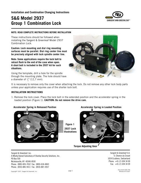
Installation <strong>and</strong> Combination Changing <strong>Instructions</strong><br />
S&G Model 2937<br />
Group 1 Combination Lock<br />
NOTE: READ COMPLETE INSTRUCTIONS BEFORE INSTALLATION<br />
These instructions should be followed when<br />
installing the <strong>Sargent</strong> & <strong>Greenleaf</strong> Model 2937<br />
Combination Lock.<br />
Caution: Lock mounting <strong>and</strong> dial ring mounting<br />
surfaces must be parallel. Dial ring center line must<br />
be precisely aligned with lock spindle center line.<br />
Note: Some applications require the lock bolt to<br />
retract flush to the end of the case when open.<br />
A short bolt is included in the 2937 kit for such<br />
situations.<br />
Using the template, drill a hole for the spindle<br />
through the mounting plate. The hole should have<br />
a diameter of 1 ⁄ 2<br />
" (12,7 mm).<br />
It is necessary to remove only the cover when attaching the lock. Do not remove any other lock body parts<br />
unless your application requires use of the shorter lock bolt.<br />
INSTALLATION INSTRUCTIONS<br />
1. Remove the lock cover. Place the lock bolt in the extended position <strong>and</strong> the accelerator spring in the<br />
loaded position (Figure 1). CAUTION: Do not remove the drive cam.<br />
Accelerator Spring in Released Position<br />
Accelerator Spring in Loaded Position<br />
Figure 1<br />
2937 Lock<br />
Illustrations<br />
Torque Adjusting Gear<br />
<strong>Sargent</strong> & <strong>Greenleaf</strong>, Inc.<br />
A Wholly Owned Subsidiary of Stanley Security Solutions, Inc.<br />
PO Box 930<br />
Nicholasville, KY 40340-0930<br />
Phone: (800)-826-7652 Fax: (800)-634-4843<br />
Phone: (859)-885-9411 Fax: (859)-887-2057<br />
Copyright © 2007, <strong>Sargent</strong> & <strong>Greenleaf</strong>, Inc.<br />
page 1<br />
<strong>Sargent</strong> & <strong>Greenleaf</strong> S.A.<br />
9, Chemin du Croset<br />
1024 Ecublens, Switzerl<strong>and</strong><br />
Phone: +41-21 694 34 00<br />
Fax: +41-21 694 34 09<br />
Document 630-754<br />
Revised 9/7/2007
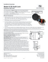
2. A hardened steel washer is attached to the lock case at the spindle hole location (Figure 2). It should<br />
be left in place during lock installation. If it comes loose during shipping or h<strong>and</strong>ling, you will need to<br />
make sure it’s in position in the case cavity provided for it before the lock body is attached to the safe’s<br />
mounting plate (Figure 3). You may find it helpful to apply a thin film of grease or a small spot of glue to<br />
the underside of the washer to make it adhere to the lock case during the mounting process. Do not let<br />
grease or glue creep into the lock case.<br />
Figure 2<br />
Figure 3<br />
2. Mount the lock in place with four 1 ⁄ 4<br />
-20 attaching screws (provided).<br />
3. Attach the dial ring by loosely installing the attaching screws to hold the dial ring in place for alignment.<br />
The dial ring opening index should be at the 12 o’clock center position.<br />
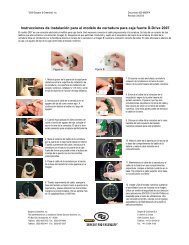
4. To install the dial, hold the drive cam in place with one h<strong>and</strong> <strong>and</strong> thread the dial/spindle assembly into<br />
the cam until the dial comes to a stop against the surface of the dial ring.<br />
Caution: When threading the dial into the cam, do not allow the cam to slide outward against the accelerator<br />
spring. The accelerator spring can be easily damaged in this manner.<br />
Figure 4<br />
Dial Edges<br />
Flush with Ring<br />
Misaligned<br />
Aligned<br />
Note that the small gap between the dial <strong>and</strong> ring is uneven when the dial ring is misaligned<br />
(see arrow above), but is even when the dial ring is properly aligned. The center of a properly<br />
aligned dial ring is in perfect alignment with the center of the spindle hole in the drive cam.<br />
5.The alignment of the dial <strong>and</strong> ring is critical to the proper<br />
operation of the lock. Perfect alignment must be obtained.<br />
The dial should be flush <strong>and</strong> centered with the top surface<br />
of the dial ring for true centering (Figure 4).<br />
Figure 5<br />
6. Measure the excess spindle that projects beyond the drive<br />
cam (Figure 5).<br />
Excess Spindle<br />
page 2
7. Remove the dial, cut off the excess spindle, <strong>and</strong> remove any burrs from the end. You may also find that<br />
the spindle threads more easily into the drive cam after cutting if the spindle end is beveled slightly.<br />
8. Tighten the dial ring screws. Figure 6<br />
9. Place a flat washer, the compression spring, <strong>and</strong> another flat washer over the spindle <strong>and</strong> into the recess<br />
at the dial hub (Figure 6).<br />
10. Insert the dial into the lock, but remember that you should not allow the cam to slide outward against<br />
the accelerator spring, possibly damaging it. Hold the drive cam in place, positioned for its gate<br />
(Figure 7) to receive the nose of the drop lever, <strong>and</strong> thread the dial into the cam until the dial stops.<br />
Gate<br />
Figure 7<br />
VU Mount<br />
Spline Key LH Mount RH Mount<br />
VD Mount<br />
11. Turn the dial counterclockwise until zero is aligned with the opening index of the dial ring; then turn<br />
the dial one turn farther counterclockwise. When this is done, the proper spindle spline keyway <strong>and</strong><br />
drive cam spline keyway should be closely aligned (vertical-up—VU, right-h<strong>and</strong>—RH, etc.).<br />
12. Insert the spline key with the tip toward the edge of the cam. Tap it lightly. Be very careful to avoid<br />
striking the stainless steel roller that is attached to the top surface of the drive cam. With the spline<br />
key inserted fully, the dial must turn freely with no rubbing or interference.<br />
Note: Before installing the lock‘s cover, check for proper in <strong>and</strong> out travel of the dial to make sure the<br />
accelerator spring operates correctly.<br />
13. Turn the dial at least one complete revolution in either direction <strong>and</strong> then stop at zero. The accelerator<br />
spring should now be in the loaded position.<br />
14. Hold the cover in place on the lock <strong>and</strong> push the dial in at zero. Release the dial. Remove the<br />
cover <strong>and</strong> check the position of the accelerator spring. It should be in the released position. If the<br />
accelerator spring is not in the released position, the dial has not been backed out of the cam far<br />
enough, <strong>and</strong> the condition must be corrected. Remove the spline key, hold the cam, <strong>and</strong> rotate the dial<br />
one additional full turn counterclockwise. Install a new spline key <strong>and</strong> repeat steps 13 <strong>and</strong> 14.<br />
page 3
15. Turn the dial at least one complete revolution in either direction; then stop at 50. The accelerator<br />
spring should now be in the loaded position.<br />
16. Hold the lock cover in place <strong>and</strong> push the dial in at 50. The accelerator spring should not release. If<br />
the accelerator spring does release, the spindle must be turned clockwise into the cam one revolution<br />
<strong>and</strong> the lock checked again, beginning at step 13.<br />
17. Dial the factory combination (4 times left to 50, right to 0, push in, let the dial out, turn right until<br />
the dial comes to a stop at about 85) <strong>and</strong> observe the drop lever falling into the drive cam. Repeat this<br />
step at least three times, checking to make sure the drop lever falls into the drive cam gate each time.<br />
18. When the accelerator spring is operating properly, the cover may be attached to the lock <strong>and</strong> the Spy-<br />
Proof ® dial cover installed.<br />
INSTALLING THE SPY-PROOF ® DIAL COVER<br />
The Spy-Proof ® dial cover is attached to the dial<br />
ring at two points located on either side of the dial<br />
ring. The cover is attached using a 4-40 socket<br />
head cap screw (requiring a 3/32” hex driver) at<br />
each of the two locations. The Spy-Proof ® cover<br />
does not need to be removed for changing the<br />
lock's combination.<br />
INSTALLING THE SHORT BOLT<br />
For applications requiring the lock bolt to retract<br />
flush to the end of the lock case, install the<br />
included short bolt as follows. The bolt change can be done before or after lock installation.<br />
Use the change key rib or a large<br />
flat-blade screwdriver to loosen <strong>and</strong><br />
remove the lever screw.<br />
Holding the lever in place, <strong>and</strong><br />
depressing the relock trigger arm<br />
as shown, remove the lock bolt.<br />
Slide the short bolt into the lock<br />
case while holding down the relock<br />
trigger arm. Re-install the lever<br />
screw, being careful to move the<br />
lever as little as possible.<br />
Tighten the lever screw firmly, using<br />
either the change key rib or a large<br />
flat-tip screwdriver.<br />
DIALING THE COMBINATION TO OPEN THE LOCK<br />
Before operating the lock or changing the combination, read these instructions thoroughly.<br />
On the dial ring are two index marks. The one at the top is for normal dialing <strong>and</strong> opening. The index to the<br />
left is provided for use only when changing the combination.<br />
Turn the dial slowly <strong>and</strong> steadily. If, after turning the correct<br />
number of revolutions, any number is turned beyond the index<br />
mark, the entire series of combination numbers must be redialed.<br />
You cannot back up to a number if you pass it when you<br />
meant to stop on it. Each time a selected number is aligned<br />
with the opening index, it counts as one revolution, even if you<br />
only have to turn the dial a few numbers to achieve the initial<br />
alignment.<br />
page 4<br />
Changing Index<br />
Opening Index
CAUTION: The dial should not be pushed in until the combination has been dialed <strong>and</strong> the dial returned to zero<br />
at the opening index.<br />
TO UNLOCK ON A FACTORY COMBINATION<br />
1. Turn the dial counterclockwise (left), stopping when 50 is aligned with the opening index the fourth<br />
time.<br />
2. Turn the dial clockwise (right), stopping when 0 is aligned with the opening index the first time.<br />
3. With 0 aligned at the opening index, push the dial in firmly, then release it to activate the lever<br />
assembly.<br />
4. Turn the dial clockwise until the bolt retracts. The dial should come to a positive stop at about 85. If the<br />
combination has been correctly dialed, the safe or cabinet may be opened.<br />
TO LOCK<br />
Turn the dial counterclockwise (left) at least five complete revolutions for maximum security.<br />
COMBINATION CHANGING FROM 50 - 0<br />
Make up a new combination, selecting three numbers of your own choosing. Do not set the third number<br />
of the combination between 90 <strong>and</strong> 99 or 0 <strong>and</strong> 10. This area is known as the forbidden zone. Adjacent<br />
combination numbers should be at least 5 numbers apart. Numbers that end with 0 or 5 should not be<br />
used for all combination numbers. Do not use strictly ascending (ex. 22-45-83) or descending (ex. 83-45-<br />
22) combination sequences. Also, do not use numbers someone could easily guess.<br />
Caution: Only use change key 6720-043-001 on the 2937 series lock. Other keys will not function properly<br />
<strong>and</strong> may damage the lock.<br />
1. Turn the dial counterclockwise, stopping when 50 is aligned with the changing index the fourth time.<br />
2. Leave the dial on 50 at the changing index <strong>and</strong> insert the change key into the hole in the back of the<br />
lock. Insert the key until the wing is entirely inside the lock <strong>and</strong> the key comes to a positive stop.<br />
WARNING: Never insert the change key into the lock when the cover is removed. Always be certain the change<br />
key is entirely within the lock before turning the key.<br />
3. Turn the key one quarter turn counterclockwise. With the change key in this position, turn the dial<br />
counterclockwise, stopping when the first number of the newly selected combination aligns with the<br />
changing index the FOURTH time.<br />
4. Turn the dial clockwise, stopping when the second number of the combination is aligned with the<br />
changing index the THIRD time.<br />
5. Turn the dial counterclockwise, stopping when the third number is aligned with the changing index the<br />
SECOND time. Holding the dial in this position, turn the change key one quarter turn clockwise to relock<br />
the wheels with the new combination installed. Remove the change key from the lock.<br />
The new combination you have selected is now set. After changing the opening combination, the lock<br />
should be opened <strong>and</strong> locked several times with the safe door open. Once the new combination has been<br />
successfully tested, the safe door can be closed <strong>and</strong> locked.<br />
page 5
TO UNLOCK ON A SAMPLE COMBINATION OF 50 - 25 - 50<br />
1. Turn the dial counterclockwise, stopping when 50 is aligned with the opening index the fourth time.<br />
2. Turn the dial clockwise, stopping when 25 is aligned with the opening index the third time.<br />
3. Turn the dial counterclockwise, stopping when 50 is aligned with the opening index the second time.<br />
4. Turn the dial clockwise, stopping when 0 is aligned with the opening index the first time.<br />
5. When 0 is aligned with the opening index, push the dial in firmly, then release it to activate the lever<br />
assembly.<br />
6. Turn the dial farther clockwise until it comes to a positive stop near 85, indicating that the lock bolt has<br />
retracted. If the combination has been correctly dialed, the safe or cabinet may be opened.<br />
This procedure can be used with any three number combination, substituting selected numbers for the<br />
numbers 50 - 25 - 50.<br />
CAUTION: The dial should not be pushed in at 0 until all three numbers have been dialed <strong>and</strong> 0 is aligned with<br />
the opening index.<br />
COMBINATION CHANGING FROM A SAMPLE COMBINATION OF 50 - 25 - 50<br />
1. Turn the dial counterclockwise, stopping when 50 is aligned with the changing index the fourth time.<br />
2. Turn the dial clockwise, stopping when 25 is aligned with the changing index the third time.<br />
3. Turn the dial counterclockwise, stopping when 50 is aligned with the changing index the second time.<br />
4. Leave the dial with the last number at the changing index <strong>and</strong> insert the change key in the hole in the<br />
back of the lock. Insert the key until the wing is entirely inside the lock <strong>and</strong> comes to a positive stop.<br />
5. Turn the key one quarter turn counterclockwise. With the change key in this position, turn the dial<br />
counterclockwise, stopping when the first number of the newly selected combination aligns with he<br />
changing index the FOURTH time.<br />
6. Turn the dial clockwise, stopping when the second number of the new combination is aligned with the<br />
changing index the THIRD time.<br />
7. Turn the dial counterclockwise, stopping when the third number of the new combination is aligned with<br />
the changing index the SECOND time. Holding the dial in this position, turn the change key one quarter<br />
turn clockwise to relock the wheels with the new combination installed. Remove the change key from<br />
the lock.<br />
The new combination you have selected is now set. After changing the opening combination, the lock<br />
should be opened <strong>and</strong> locked several times with the safe door open. Once the new combination has been<br />
successfully tested, the safe door can be closed <strong>and</strong> locked.<br />
Important: Do not select codes such as birthdays or other predictable sequences that could provide a<br />
correlation between the user <strong>and</strong> the safe combination.<br />
TORQUE ADJUSTMENT<br />
The torque adjustment feature allows the wheel pack tension to be adjusted for maximum security. To<br />
adjust torque, remove the lock cover <strong>and</strong> insert a 3 ⁄ 32<br />
“ hex wrench into the adjusting gear (see Figure 1).<br />
Turn clockwise to increase torque or counterclockwise to decrease torque. This adjustment should only be<br />
performed by a skilled technician using a specialized torque measuring tool.<br />
(continued on next page)<br />
page 6
Note: The model 2937 should not be adjusted to less than 16 or more than 24 inch-ounces of wheel pack torque.<br />
CAUTION: Whenever the lock‘s torque setting is changed, the combination must be reset.<br />
SERVICING (should only be performed by a qualified locksmith or safe technician)<br />
Periodic servicing will extend the life of your lock <strong>and</strong> is essential for maintaining security. To perform<br />
proper service, follow these instructions.<br />
1. Remove the lock cover.<br />
2. Remove the lever screw <strong>and</strong> lever assembly. Be sure to remove the lever control tension spring (small<br />
“Z” spring) so you won’t misplace it.<br />
3. Using a pair of side cutters, grip the head of the spline key as close as possible to the surface of the<br />
drive cam. Lift straight up, being careful not to bend the key. The edge of the case may be used for<br />
leverage as long as minimal force is used.<br />
4. Unscrew the dial <strong>and</strong> spindle assembly from the lock. Remove the drive cam.<br />
5. Remove the Spirolox ® retainer from the top of the wheel post.<br />
6. Remove the wheels <strong>and</strong> associated parts. Place them in sequence so they can be re-installed in the<br />
proper order.<br />
7. Remove the lock bolt. The spring-loaded ball bearing under the bolt is staked into place <strong>and</strong> should not<br />
be removed.<br />
8. Remove the dial <strong>and</strong> spindle assembly from the dial ring.<br />
CAUTION: Remove the washers <strong>and</strong> spring from the dial carefully so they can be re-installed later.<br />
The lock is now completely disassembled <strong>and</strong> ready for servicing.<br />
SERVICE AND REASSEMBLY<br />
1. Tighten the attaching screws for the dial ring <strong>and</strong> lock body.<br />
2. Wipe each wheel, the wheel post, <strong>and</strong> other bearing surfaces clean. Wipe the complete interior of the<br />
lock case clean.<br />
Note: S&G recommends Shell Aeroshell 22 ® for lock lubrication. Use of other lubricants will void the product<br />
warranty.<br />
3. Lightly (means a thin film) grease the bolt where it normally rubs against the lock case. It will be<br />
necessary to depress the relock trigger to slide the bolt back into the case.<br />
4. Be sure to carefully examine each wheel part as well as the cam <strong>and</strong> lever assembly to make sure<br />
nothing is worn or damaged.<br />
5. Lightly grease the bearing surface of the wheel post <strong>and</strong> drive cam bearing. Replace the wheels <strong>and</strong><br />
parts exactly as they were before disassembly. Reset the wheel pack torque to a value between 16 <strong>and</strong><br />
24 inch-ounces. Screw the dial/spindle assembly <strong>and</strong> cam together until snug. Hold the cam <strong>and</strong> turn<br />
the dial back one complete turn; then align the spline keyways. Insert the spline key. For proper key<br />
installation, see Figure 7 on page 3.<br />
IMPORTANT: It is recommended that a new spline key be used each time the lock is serviced.<br />
(continued on next page)<br />
page 7
6. Lightly grease the bearing surface of the lever bushing <strong>and</strong> install the lever. Tighten the lever screw<br />
snugly <strong>and</strong> carefully. Position the lever control tension spring. Be careful not to bend the accelerator<br />
spring. Lever screw torque should be between 22 <strong>and</strong> 26 inch-pounds.<br />
7. Install the lock cover. Make sure the cover screws are tight.<br />
8. Reset the combination.<br />
9. Check the combination at least three times before locking the safe.<br />
ERRORS<br />
The most frequent error in the changing procedure is dialing the number to the wrong index. Occasionally<br />
all the numbers may be dialed to the opening index rather than the changing index. More often, dialing<br />
part of the combination to the changing index <strong>and</strong> part to the opening index occurs. As long as the door is<br />
open, the error is easily corrected.<br />
PROCEDURE<br />
1. Remove the cover from the lock.<br />
2. Insert a straightened paper clip or similar instrument (NOT the change key) in the square keyways of the<br />
wheels.<br />
3. Rotate each wheel until all the keyways are in perfect alignment directly over the small hole in the<br />
bottom of the case where the tip of the change key seats during normal changing operations. There is<br />
one hole in the bottom of the case. It lines up with the change key hole in the lock cover (when the<br />
cover is in place on the lock body).<br />
4. Replace the cover <strong>and</strong> insert the change key. Replace the cover screws. NEVER INSERT A CHANGE KEY<br />
INTO THE LOCK WHEN THE COVER IS REMOVED! Always be certain that the wing of the change key is<br />
entirely within the lock before turning the key.<br />
5. Turn the change key one quarter turn counterclockwise <strong>and</strong> dial the new combination to the changing<br />
index. Once all the combination numbers have been entered into the lock, turn the key back <strong>and</strong> remove<br />
it from the lock.<br />
6. With the combination now set, try the combination at the opening index at least three times before<br />
closing the door. You should not be able to open the lock by dialing more than ½ number higher or ½<br />
number lower on any combination number you have set.<br />
LOCK TEMPLATE<br />
LEFT-HAND<br />
VERTICAL-UP<br />
13<br />
11<br />
" " ⁄16<br />
⁄16<br />
(17,5 mm)<br />
(20,6 mm)<br />
1 15 " (49,2 mm)<br />
⁄16<br />
VERTICAL-DOWN<br />
RIGHT-HAND<br />
page 8