3.4.1 - Automation Service Srl
3.4.1 - Automation Service Srl
3.4.1 - Automation Service Srl

Create successful ePaper yourself
Turn your PDF publications into a flip-book with our unique Google optimized e-Paper software.
3. TROUBLESHOOTING<br />
AND ACTION TROUBLESHOOTING B-65165E/02<br />
3.4 SPINDLE AMPLIFIER MODULE<br />
This section uses the following format for describing parameter<br />
numbers:<br />
FS0 FS15i FS16i/16, PM-D/F Description<br />
6582 3082 4082 Setting of acceleration/deceleration<br />
time<br />
The items of FS15i cover FS15. For a parameter number of FS15<br />
different from FS15i, the item is described separately.<br />
FS18i, 20i, 21i, PMi-D, 18, 20, and 21 are covered by the items of<br />
FS16i/16.<br />
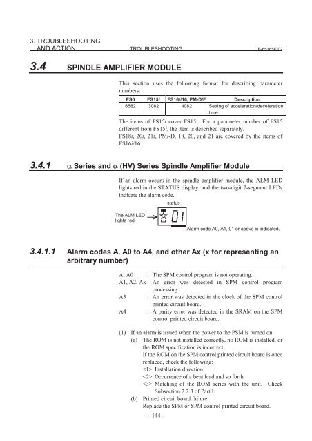
<strong>3.4.1</strong> α Series and α (HV) Series Spindle Amplifier Module<br />
If an alarm occurs in the spindle amplifier module, the ALM LED<br />
lights red in the STATUS display, and the two-digit 7-segment LEDs<br />
indicate the alarm code.<br />
status<br />
The ALM LED<br />
lights red.<br />
Alarm code A0, A1, 01 or above is indicated.<br />
<strong>3.4.1</strong>.1 Alarm codes A, A0 to A4, and other Ax (x for representing an<br />
arbitrary number)<br />
A, A0 : The SPM control program is not operating.<br />
A1, A2, Ax : An error was detected in SPM control program<br />
processing.<br />
A3 : An error was detected in the clock of the SPM control<br />
printed circuit board.<br />
A4 : A parity error was detected in the SRAM on the SPM<br />
control printed circuit board.<br />
(1) If an alarm is issued when the power to the PSM is turned on<br />
(a) The ROM is not installed correctly, no ROM is installed, or<br />
the ROM specification is incorrect<br />
If the ROM on the SPM control printed circuit board is once<br />
replaced, check the following:<br />
Installation direction<br />
Occurrence of a bent lead and so forth<br />
Matching of the ROM series with the unit. Check<br />
Subsection 2.2.3 of Part I.<br />
(b) Printed circuit board failure<br />
Replace the SPM or SPM control printed circuit board.<br />
- 144 -
3. TROUBLESHOOTING<br />
B-65165E/02 TROUBLESHOOTING AND ACTION<br />
(2) If an alarm is issued during motor activation<br />
(a) Influence of noise<br />
Referring to Chapter 5, "Installation," of "FANUC SERVO<br />
AMPLIFIER α series Descriptions (B-65162E)," check the<br />
GND-related wiring. If the signal cable of the spindle sensor<br />
is bundled with the power line of the servo motor, separate<br />
them from each other.<br />
<strong>3.4.1</strong>.2 Alarm code 01<br />
The inside temperature of the motor is higher than the specified<br />
temperature.<br />
(1) If this alarm is issued during cutting (the motor temperature is<br />
high)<br />
(a) Check the cooling state of the motor.<br />
If the cooling fan of the spindle motor is stopped, check<br />
the power supply of the cooling fan. If the cooling fan<br />
is still inoperative, replace it with a new one.<br />
When a liquid-cooled motor is used, check the cooling<br />
system.<br />
When the ambient temperature of the spindle motor is<br />
higher than the specified temperature, lower the<br />
ambient temperature to satisfy the specification.<br />
(b) If this alarm is issued even when the load meter fluctuates in<br />
a limited range, check the short-period rating. If the<br />
specified value is exceeded, reduce the load.<br />
(2) If this alarm is issued under a light load (the motor temperature is<br />
high)<br />
(a) When the frequency of acceleration/deceleration is too high<br />
Set such a use condition that the average including output at<br />
acceleration/deceleration does not exceed the continuous<br />
rating.<br />
(b) The parameters specific to the motor are not set correctly.<br />
Refer to "FANUC AC SPINDLE MOTOR α series<br />
Parameter Manual (B-65160E)."<br />
(3) If this alarm is issued when the motor temperature is low<br />
(a) The spindle sensor feedback cable is faulty.<br />
Replace the cable.<br />
(b) The SPM control printed circuit board is faulty.<br />
Replace the SPM control printed circuit board or SPM.<br />
(c) The motor (internal thermostat) is faulty.<br />
Replace the motor.<br />
- 145 -
3. TROUBLESHOOTING<br />
AND ACTION TROUBLESHOOTING B-65165E/02<br />
<strong>3.4.1</strong>.3 Alarm code 02<br />
The actual motor speed is largely deviated from the commanded speed.<br />
(1) If this alarm is issued during motor acceleration<br />
(a) The parameter setting of acceleration/deceleration time is<br />
incorrect.<br />
In the following parameter, set the value equivalent to the<br />
spindle inertia plus some margin:<br />
FS0 FS15i FS16i/16, PM-D/F Description<br />
6582 3082 4082 Setting of acceleration/deceleration<br />
time<br />
(b)<br />
The parameter for the speed detector is not set correctly.<br />
Referring to "FANUC AC SPINDLE MOTOR α series<br />
Parameter Manual (B-65160E)," set a correct value.<br />
(2) If this alarm is issued during cutting<br />
(a) The cutting load has exceeded the motor output power.<br />
Check the load meter indication, and review the use<br />
condition.<br />
(b) The parameters for output restriction are not set correctly.<br />
Check that the settings of the following parameters satisfy<br />
the machine and motor specifications:<br />
FS0 FS15i FS16i/16, PM-D/F Description<br />
6528 3028 4028 Output restriction pattern setting<br />
6529 3029 4029 Output restriction value<br />
(c)<br />
The parameters specific to the motor are not correctly.<br />
Refer to "FANUC AC SPINDLE MOTOR α series<br />
Parameter Manual (B-65160E)."<br />
- 146 -
3. TROUBLESHOOTING<br />
B-65165E/02 TROUBLESHOOTING AND ACTION<br />
<strong>3.4.1</strong>.4 Alarm code 03<br />
The fuse of the DC link has blown. (The voltage at the DC link is<br />
insufficient.) This alarm is checked when emergency stop is cancelled.<br />
(1) If this alarm is issued during spindle operation (rotation)<br />
The fuse of the DC link inside the SPM has probably blown. So,<br />
replace the SPM. This alarm may be caused by the following:<br />
Power line short-circuited to ground<br />
Motor winding short-circuited to ground<br />
IGBT or IPM module failure<br />
(2) If the PSM input magnetic contactor is once turned on and is<br />
turned off with this alarm when emergency stop is cancelled or the<br />
CNC is started (When two spindles are connected, the magnetic<br />
contactor may not be turned off.)<br />
(a) The DC link wire is not connected.<br />
Check the DC link (TB1) wiring for errors.<br />
(b) A cable is faulty.<br />
Pin 9 of the interface cable (JX1B-JX1A) between the PSM<br />
and SPM may be short-circuited to 0V. Replace the cable.<br />
(c) The fuse of the DC link inside the SPM has blown.<br />
Replace the SPM.<br />
<strong>3.4.1</strong>.5 Alarm code 04<br />
It is detected that the 3-phase input to the main circuit of the PSM has<br />
an open phase.<br />
(1) If the PSM indicates alarm code 6<br />
Troubleshoot according to the description of alarm code 6<br />
provided in Section 3.1 of Part II.<br />
(2) If the PSM indicates no alarm<br />
(a) A cable is faulty.<br />
The connection cable between the PSM (JX1B) and SPM<br />
(JX1A) is faulty. Replace the cable.<br />
(b) The SPM is faulty.<br />
Replace the SPM or SPM control printed circuit board.<br />
- 147 -
3. TROUBLESHOOTING<br />
AND ACTION TROUBLESHOOTING B-65165E/02<br />
<strong>3.4.1</strong>.6 Alarm code 07<br />
The motor rotates at a speed exceeding 115% (standard setting) of the<br />
maximum allowable speed.<br />
(1) If this alarm is issued during spindle synchronization<br />
If the activation (SFR, SRV) of the motor on one side is turned off<br />
then back on in the spindle synchronization mode, the spindle<br />
motor is accelerated to correct a position error built up during the<br />
period, thus causing this alarm. Modify the ladder so that SFR<br />
and SRV are not turned off in the spindle synchronization mode.<br />
(2) If this alarm is issued while the motor is stopped<br />
(a) The connection cable of the spindle sensor is faulty.<br />
Check if the cable of the spindle sensor built into the motor<br />
(BZ sensor when a built-in motor is used) is disconnected,<br />
and replace the cable as required.<br />
(b) The spindle sensor built into the motor is not adjusted<br />
correctly.<br />
Adjust the sensor according to Subsection 4.3.4 of Part I.<br />
<strong>3.4.1</strong>.7 Alarm code 09<br />
The temperature of the heat sink of the SPM main circuit has risen to<br />
the set value. This alarm is issued for SPM-15 and up or SPM-15HV<br />
and later. With SPM-2.2 to SPM-11 and SPM-11HV, however, alarm<br />
code 12 is issued for the same cause.<br />
(1) If this alarm is issued during cutting (the heat sink temperature is<br />
high)<br />
(a) If this alarm is issued when the load meter reads a value<br />
below the continuous rating of the amplifier, check the<br />
cooling state of the heat sink.<br />
If the cooling fan is stopped, check the power supply<br />
(connector CX1A/B). If the cooling fan is still<br />
inoperative, replace the SPM with a new one.<br />
When the ambient temperature is higher than the<br />
specified temperature, lower the ambient temperature<br />
to satisfy the specification.<br />
(b) When this alarm is issued because the load meter reads a<br />
value above the continuous rating of the amplifier, improve<br />
the use method.<br />
- 148 -
3. TROUBLESHOOTING<br />
B-65165E/02 TROUBLESHOOTING AND ACTION<br />
(c)<br />
When the heat sink on the back of the amplifier is too dirty,<br />
clean the heat sink, for example, by blowing air. Consider<br />
the use of a structure that prevents the heat sink from being<br />
directly exposed to coolant.<br />
(2) If this alarm is issued under a light load (the heat sink temperature<br />
is high)<br />
(a) When the frequency of acceleration/deceleration is too high<br />
Set such a use condition that the average including output at<br />
acceleration/deceleration does not exceed the continuous<br />
rating.<br />
(b) The parameters specific to the motor are not set correctly.<br />
Refer to "FANUC AC SPINDLE MOTOR α series<br />
Parameter Manual (B-65160E)."<br />
(3) If this alarm is issued when the heat sink temperature is low<br />
Replace the SPM.<br />
<strong>3.4.1</strong>.8 Alarm code 11<br />
The PSM detected that the DC link voltage was excessively high.<br />
(1) If the PSM indicates alarm code 7<br />
Troubleshoot according to the description of alarm code 7<br />
provided in Section 3.1 of Part II.<br />
(2) If the PSM indicates no alarm<br />
(a) A cable is faulty.<br />
The connection cable between the PSM (JX1B) and SPM<br />
(JX1A) is faulty. Replace the cable.<br />
(b) The SPM is faulty.<br />
Replace the SPM or SPM control printed circuit board.<br />
- 149 -
3. TROUBLESHOOTING<br />
AND ACTION TROUBLESHOOTING B-65165E/02<br />
<strong>3.4.1</strong>.9 Alarm code 12<br />
An excessively large current flowed into the DC link of the main<br />
circuit.<br />
With SPM-2.2 to SPM-11 and SPM-11HV, this alarm indicates that the<br />
power module (IPM) of the main circuit detected an error such as an<br />
excessive load, overcurrent, or low control supply voltage.<br />
(1) If this alarm is issued on SPM-2.2 to SPM-11 and SPM-11HV<br />
Check alarm code 09 as well.<br />
(2) If this alarm is issued immediately after a spindle rotation<br />
command is specified<br />
(a) The motor power line is faulty.<br />
Check for a short circuit between motor power lines and<br />
short-circuit to ground, and replace the power line as<br />
required.<br />
(b) The motor winding has an insulation failure.<br />
If the motor is short-circuited to ground, replace the motor.<br />
(c) The parameters specific to the motor are not set correctly.<br />
Refer to "FANUC AC SPINDLE MOTOR α series<br />
Parameter Manual (B-65160E)."<br />
(d) The SPM is faulty.<br />
A power element (IGBT, IPM) may be destroyed. Replace<br />
the SPM.<br />
(3) If this alarm is issued during spindle rotation<br />
(a) A power element is destroyed.<br />
A power element (IGBT, IPM) may be destroyed. Replace<br />
the SPM.<br />
If the amplifier setting condition is not satisfied, or cooling is<br />
insufficient because the heat sink is dirty, the power<br />
elements may be destroyed.<br />
When the heat sink on the back of the amplifier is too dirty,<br />
clean the heat sink, for example, by blowing air. Consider<br />
the use of a structure that prevents the heat sink from being<br />
directly exposed to coolant.<br />
For the setting condition, refer to "FANUC SERVO<br />
AMPLIFIER α series Descriptions (B-65162E)."<br />
(b) The parameters specific to the motor are not set correctly.<br />
Referring to "FANUC AC SPINDLE MOTOR α series<br />
Parameter Manual (B-65160E)," check the parameters<br />
specific to the motor.<br />
(c) Speed sensor signal error<br />
Check the spindle sensor signal waveform according to<br />
Subsection 4.3.4 of Part I. If an error is found, make an<br />
adjustment or replace the detector as required.<br />
- 150 -
3. TROUBLESHOOTING<br />
B-65165E/02 TROUBLESHOOTING AND ACTION<br />
<strong>3.4.1</strong>.10 Alarm code 13<br />
The memory inside the CPU is faulty. A check is made when the power<br />
is turned on.<br />
If this alarm is issued, replace the SPM or SPM control printed circuit<br />
board.<br />
<strong>3.4.1</strong>.11 Alarm code 15<br />
In output switching control or spindle switching control, the switching<br />
operation sequence was not executed correctly.<br />
This alarm is issued if one second or more elapses from the transition of<br />
a switch request signal (SPSL or RSL) until a power line state check<br />
signal (MCFN, MFNHG, RCH, or RCHHG) makes a transition.<br />
Troubleshooting when this alarm is issued<br />
(a) The magnetic contactor (switch unit) for power line<br />
switching is faulty.<br />
If the contact is inoperative, check the power supply of the<br />
magnetic contactor. If the magnetic contactor is still<br />
inoperative, replace the magnetic contactor.<br />
(b) The I/O unit or wiring for checking the contact of the<br />
magnetic contactor is faulty.<br />
If a defect is found in the I/O unit or wiring, replace the I/O<br />
unit or wiring.<br />
(c) The sequence (ladder) is incorrect.<br />
Modify the sequence so that switching is completed within 1<br />
second. For details of the signals, refer to Chapter 10,<br />
"Interface Signals," in "FANUC SERVO AMPLIFIER α series<br />
Descriptions (B-65162E)."<br />
<strong>3.4.1</strong>.12 Alarm code 16<br />
The memory (RAM) is faulty. A check is made when the power is<br />
turned on.<br />
If this alarm is issued, replace the SPM or SPM control printed circuit<br />
board.<br />
- 151 -
3. TROUBLESHOOTING<br />
AND ACTION TROUBLESHOOTING B-65165E/02<br />
<strong>3.4.1</strong>.13 Alarm codes 19 and 20<br />
The offset voltage of the phase U (alarm code 19) or phase V (alarm<br />
code 20) current detection circuit is excessively high. A check is made<br />
when the power is turned on.<br />
If this alarm is issued, replace the SPM. If this alarm is issued<br />
immediately after the SPM control printed circuit board is replaced,<br />
check the plugging of the connectors (CN1, CN3, and CN4) between<br />
the power unit and SPM control printed circuit board.<br />
<strong>3.4.1</strong>.14 Alarm code 24<br />
The power to the CNC is turned off. (This symptom does not represent<br />
an error.) Serial communication data transferred between the CNC and<br />
spindle amplifier module contains an error.<br />
Troubleshooting when this alarm is issued<br />
(a) Noise occurring between the CNC and spindle amplifier<br />
module (connected via an electric cable) caused an error in<br />
communication data.<br />
Check the condition for maximum wiring length.<br />
Referring to Chapter 9, "Connection," in "FANUC SERVO<br />
AMPLIFIER α series Descriptions (B-65162E)," check the<br />
condition of electric cable connection.<br />
(b) Noise exercises an influence because a communication cable<br />
is bundled with the power line.<br />
If a communication cable is bundled with the power line for<br />
the motor, separate them from each other.<br />
(c) A cable is faulty.<br />
Replace the cable.<br />
If an optical I/O link adapter is used, the optical link adapter<br />
or optical cable may be faulty.<br />
(d) The SPM is faulty.<br />
Replace the SPM or SPM control printed circuit board.<br />
(e) The CNC is faulty.<br />
Replace the board or module related to the serial spindle.<br />
<strong>3.4.1</strong>.15 Alarm code 25<br />
Serial communication between the CNC and spindle amplifier module<br />
stopped.<br />
Troubleshoot as in the case of alarm code 24.<br />
- 152 -
3. TROUBLESHOOTING<br />
B-65165E/02 TROUBLESHOOTING AND ACTION<br />
<strong>3.4.1</strong>.16 Alarm code 26<br />
The sensor signal (for speed control) for Cs contour control has an<br />
error.<br />
When a high-resolution magnetic pulse coder is used with SPM<br />
TYPE2 (using both of the JY2 and JY5 connectors), the amplitude<br />
of the sensor signal on the high-resolution side (1000 λ) of the<br />
high-resolution magnetic pulse coder built into the motor on the<br />
JY2 side is excessively small.<br />
When a built-in motor is used with SPM TYPE2 (using only the<br />
JY5 connector), the amplitude of the sensor signal on the highresolution<br />
side (1000 to 3000 λ) of the high-resolution magnetic<br />
pulse coder is excessively small.<br />
When SPM TYPE4 is used, the amplitude of the spindle sensor<br />
(MZ sensor) built into the motor connected to JY2 is excessively<br />
small.<br />
(1) If this alarm is issued when the motor is deactivated<br />
(a) The setting of a parameter is incorrect.<br />
Referring to "FANUC AC SPINDLE MOTOR α series<br />
Parameter Manual (B-65160E)," check the parameter for<br />
sensor setting.<br />
(b) The sensor is not adjusted correctly, or the cable is<br />
disconnected.<br />
Adjust the sensor signal according to Subsection 4.3.4 of<br />
Part I of this manual. If the signal is not observed, replace<br />
the cable and sensor.<br />
(c) The printed circuit board is faulty.<br />
Replace the SPM or SPM control printed circuit board.<br />
(2) If this alarm is issued when the cable is moved (as in the case<br />
where the spindle moves)<br />
(a) The connector has a bad contact, or the cable is<br />
disconnected.<br />
The conductor may be broken. Replace the cable. If coolant<br />
has penetrated into the connector, clean the connector.<br />
- 153 -
3. TROUBLESHOOTING<br />
AND ACTION TROUBLESHOOTING B-65165E/02<br />
Sensor<br />
Shielded cable<br />
The cable is<br />
connected to the<br />
pin specified in the<br />
specifications on<br />
the sensor side.<br />
S<br />
P<br />
M<br />
The cable is<br />
connected to<br />
pin 10 on the<br />
SPM side.<br />
(3) If this alarm is issued when the motor rotates<br />
(a) The shielding of the cable between the preamplifier or MZ<br />
sensor (for TYPE4) and the SPM is faulty.<br />
Referring to Chapter 9, "Connection," in "FANUC SERVO<br />
AMPLIFIER α series Descriptions (B-65162E)," check the<br />
shielding of the cable.<br />
(b) The signal cable is bundled with the servo motor power line.<br />
If the cable between the preamplifier or MZ sensor (for<br />
TYPE4) and the SPM is bundled with the servo motor power<br />
line, separate them from each other.<br />
(c) Improve the cable routing between the motor and<br />
preamplifier.<br />
If the cables (including those within a terminal box)<br />
extending from the motor to the preamplifier are close to the<br />
power line, separate the cables from the power line.<br />
- 154 -
3. TROUBLESHOOTING<br />
B-65165E/02 TROUBLESHOOTING AND ACTION<br />
<strong>3.4.1</strong>.17 Alarm code 27<br />
The sensor signal (position coder signal) for position control is<br />
abnormal.<br />
The signal of the α position coder is disconnected (for all types).<br />
When an MZ or BZ sensor is used with SPM TYPE1 (using the<br />
JY2 connector), the amplitude of the sensor signal is excessively<br />
small.<br />
When a separate built-in sensor is used with SPM TYPE2 (using<br />
the JY2 and JY5 connectors), the amplitude of the spindle sensor<br />
signal on the JY2 side is excessively small.<br />
When a high-resolution magnetic pulse coder is used with SPM<br />
TYPE2 (using the JY2 and JY5 connectors), the amplitude of the<br />
sensor signal on the low-resolution side (128 to 384 λ) on the JY5<br />
side is excessively small.<br />
When SPM TYPE4 is used, the amplitude of the spindle sensor<br />
signal connected to JY5 is excessively small.<br />
α position coder<br />
Sensor<br />
Shielded cable<br />
S<br />
P<br />
M<br />
Connected to the frame<br />
ground via a cable clamp.<br />
(1) If this alarm is issued when the motor is deactivated<br />
(a) The setting of a parameter is incorrect.<br />
Referring to Chapter 2 of "FANUC AC SPINDLE MOTOR<br />
α series Parameter Manual (B-65160E)," check the<br />
parameter for sensor setting.<br />
(b) The cable connected to JY4 is disconnected. (α position<br />
coder)<br />
When the α position coder is used, adjustment is impossible.<br />
Replace the cable.<br />
(c) The sensor is not adjusted correctly.<br />
Adjust the sensor signal according to Subsection 4.3.4 of<br />
Part I of this manual. If the sensor signal cannot be adjusted<br />
correctly, or the sensor signal is not observed, replace the<br />
connection cable and sensor.<br />
(d) The SPM is faulty.<br />
Replace the SPM or SPM control printed circuit board.<br />
(2) If this alarm is issued when the cable is moved (as in the case<br />
where the spindle moves)<br />
(a) The connector has a bad contact, or the cable is<br />
disconnected.<br />
The conductor may be broken. Replace the cable. If coolant<br />
has penetrated into the connector, clean the connector.<br />
- 155 -
3. TROUBLESHOOTING<br />
AND ACTION TROUBLESHOOTING B-65165E/02<br />
Other sensors<br />
Sensor<br />
Shielded cable<br />
The cable is<br />
connected to the<br />
pin specified in the<br />
specifications on<br />
the sensor side.<br />
S<br />
P<br />
M<br />
The cable is<br />
connected to<br />
pin 10 on the<br />
SPM side.<br />
(3) If this alarm is issued when the motor rotates<br />
(a) The shielding of the cable between the sensor and the SPM is<br />
faulty.<br />
Referring to Chapter 9, "Connection," in "FANUC SERVO<br />
AMPLIFIER α series Descriptions (B-65162E)," check the<br />
shielding of the cable.<br />
(b) The signal cable is bundled with the servo motor power line.<br />
If the cable between the sensor and the SPM is bundled with<br />
the servo motor power line, separate them from each other.<br />
<strong>3.4.1</strong>.18 Alarm code 28<br />
The sensor signal (for position control) for Cs contour control is<br />
abnormal.<br />
When a high-resolution magnetic pulse coder is used with SPM<br />
TYPE2 (using both of the JY2 and JY5 connectors), the amplitude<br />
of the sensor signal on the high-resolution side (1000 to 3000 λ) of<br />
the high-resolution magnetic pulse coder on the JY5 side is<br />
excessively small.<br />
When SPM TYPE4 is used, the amplitude of the spindle sensor<br />
(MZ sensor) built into the motor connected to JY5 is excessively<br />
small.<br />
Troubleshoot as in the case of alarm code 26.<br />
- 156 -
3. TROUBLESHOOTING<br />
B-65165E/02 TROUBLESHOOTING AND ACTION<br />
<strong>3.4.1</strong>.19 Alarm code 29<br />
An excessive load (standard setting: load meter reading of 9 V) has<br />
been applied continuously for a certain period (standard setting: 30<br />
seconds).<br />
(1) If this alarm is issued during cutting<br />
Check the load meter, and review the cutting condition.<br />
(2) If this alarm is issued during a stop<br />
(a) The spindle is locked.<br />
Check the sequence to see if the spindle is locked when a<br />
command for very slow movement is specified or orientation<br />
is specified for the spindle.<br />
(3) If the spindle does not rotate as specified (the spindle rotates at a<br />
very low speed) and this alarm is issued<br />
(a) The setting of a parameter is incorrect.<br />
Referring to "FANUC AC SPINDLE MOTOR α series<br />
Parameter Manual (B-65160E)," check the parameter for<br />
sensor setting.<br />
(b) The phase sequence of the motor power line is incorrect.<br />
(c) The feedback cable of the motor has a problem.<br />
Check if the phase A/B signals are connected correctly.<br />
(d) The feedback cable of the motor is faulty.<br />
Rotate the motor manually to see if a speed is indicated in the<br />
item of motor speed on the CNC diagnosis screen or on the<br />
spindle check board. If no speed indication is provided,<br />
replace the cable or spindle sensor (or motor).<br />
(4) If the spindle does not rotate as specified (the spindle does not<br />
rotate at all) and this alarm is issued<br />
(a) The power line is abnormal.<br />
Check if the motor power line is connected normally. If<br />
spindle switching or output switching is performed, check if<br />
the magnetic contactor is on.<br />
(b) The SPM is faulty.<br />
Replace the SPM.<br />
- 157 -
3. TROUBLESHOOTING<br />
AND ACTION TROUBLESHOOTING B-65165E/02<br />
<strong>3.4.1</strong>.20 Alarm code 30<br />
An excessively large current is detected at the input of the 3-phase main<br />
circuit of the PSM.<br />
(1) If the PSM indicates alarm code 1<br />
Troubleshoot according to the description of alarm code 1<br />
provided in Section 3.1 of Part II.<br />
(2) If the PSM indicates no alarm<br />
(a) A cable is faulty.<br />
The connection cable between the PSM (JX1B) and SPM<br />
(JX1A) is faulty. Replace the cable.<br />
(b) The SPM is faulty.<br />
Replace the SPM or SPM control printed circuit board.<br />
<strong>3.4.1</strong>.21 Alarm code 31<br />
The motor failed to rotate as specified, and has stopped or is rotating at<br />
a very low speed.<br />
(1) If the motor rotates at a very low speed and this alarm is issued<br />
(a) The setting of a parameter is incorrect.<br />
Referring to "FANUC AC SPINDLE MOTOR α series<br />
Parameter Manual (B-65160E)," check the parameter for<br />
sensor setting.<br />
(b) The motor phase sequence is incorrect.<br />
Check if the motor phase sequence is correct.<br />
(c) The feedback cable of the motor has a problem.<br />
Check if the phase A/B signals are connected correctly.<br />
(d) The feedback cable of the motor is faulty.<br />
Rotate the motor manually to see if a speed is indicated in the<br />
item of motor speed on the CNC diagnosis screen or on the<br />
spindle check board. If no speed indication is provided,<br />
replace the cable or spindle sensor (or motor).<br />
(2) If the motor does not rotate at all and this alarm is issued<br />
(a) The sequence for locking the spindle is incorrect.<br />
Check the sequence to see if the spindle is locked.<br />
(b) The power line is faulty.<br />
Check if the power line is connected to the motor correctly.<br />
If spindle switching or winding switching is performed,<br />
check if the magnetic contactor is on.<br />
(c) The SPM is faulty.<br />
Replace the SPM.<br />
- 158 -
3. TROUBLESHOOTING<br />
B-65165E/02 TROUBLESHOOTING AND ACTION<br />
<strong>3.4.1</strong>.22 Alarm code 32<br />
LSI memory for serial communication is abnormal. A check is made<br />
when the power is turned on.<br />
If this alarm is issued, replace the SPM or SPM control printed circuit<br />
board.<br />
<strong>3.4.1</strong>.23 Alarm code 33<br />
The PSM could not be charged within a specified time.<br />
PSM input has an open phase.<br />
(1) If the PSM indicates alarm code 5<br />
Troubleshoot according to the description of alarm code 5<br />
provided in Section 3.1 of Part II.<br />
(2) If the PSM indicates no alarm<br />
(a) A cable is faulty.<br />
The connection cable between the PSM (JX1B) and SPM<br />
(JX1A) is faulty. Replace the cable.<br />
(b) The SPM is faulty.<br />
Replace the SPM or SPM control printed circuit board.<br />
<strong>3.4.1</strong>.24 Alarm code 34<br />
Parameter data outside the specifiable range was set.<br />
Troubleshooting when this alarm is issued<br />
Connect the spindle check board.<br />
The spindle check board displays "AL-34" and "F-xxx"<br />
alternately. "F-xxx" indicates a parameter number outside the<br />
specifiable range. For the correspondence between the CNC<br />
parameter numbers and "F-xxx," refer to "FANUC AC SPINDLE<br />
MOTOR α series Parameter Manual (B-65160E)."<br />
- 159 -
3. TROUBLESHOOTING<br />
AND ACTION TROUBLESHOOTING B-65165E/02<br />
<strong>3.4.1</strong>.25 Alarm code 35<br />
The gear ratio set in a parameter exceeds the value range allowable for<br />
internal processing. This alarm is issued with a parameter related to<br />
orientation of magnetic sensor type.<br />
Troubleshooting when this alarm is issued<br />
(a) The gear ratio set in a parameter is incorrect.<br />
Check if an excessively large gear ratio is set.<br />
FS0 FS15i FS16i/16, PM-D/F Description<br />
6556 3056 4056 Gear ratio between the spindle and<br />
to to<br />
to<br />
6559 3059 4059<br />
motor<br />
6560<br />
to<br />
6563<br />
3060<br />
to<br />
3063<br />
4060<br />
to<br />
4063<br />
Position gain at orientation<br />
<strong>3.4.1</strong>.26 Alarm code 36<br />
The error counter overflowed.<br />
(1) The setting of a parameter is incorrect.<br />
(a) The gear ratio set in a parameter is incorrect.<br />
Check if an excessively large gear ratio is set.<br />
(b) The setting of a position gain is incorrect.<br />
If the gear ratio data is correct, increase the position gain.<br />
(c) The setting of a position detector mounting direction or the<br />
setting of spindle and motor rotation directions is incorrect.<br />
FS0 FS15i FS16i/16, PM-D/F Description<br />
6556 3056 4056 Gear ratio between the spindle and<br />
to to<br />
to<br />
6559 3059 4059<br />
motor<br />
6565<br />
to<br />
6568<br />
6569<br />
to<br />
6572<br />
3065<br />
to<br />
3068<br />
3069<br />
to<br />
3072<br />
4065<br />
to<br />
4068<br />
4069<br />
to<br />
4072<br />
Position gain in the servo<br />
mode/spindle synchronization<br />
Position gain in Cs contour control<br />
(2) Sequence error<br />
(a) Check if the motor is deactivated (by turning off SFR/SRV)<br />
in a position control mode (rigid tapping, Cs contour control,<br />
or spindle synchronization).<br />
- 160 -
3. TROUBLESHOOTING<br />
B-65165E/02 TROUBLESHOOTING AND ACTION<br />
<strong>3.4.1</strong>.27 Alarm code 37<br />
After emergency stop signal input, the motor is accelerated without<br />
being decelerated. This alarm is issued also when the motor is not<br />
deactivated (the motor is not decelerated completely) when the<br />
acceleration/deceleration time (initial parameter setting: 10 seconds)<br />
has elapsed after emergency stop signal input.<br />
Troubleshooting when this alarm is issued<br />
(a) The parameter setting of the speed detector is incorrect.<br />
Referring to Chapter 1 in "FANUC AC SPINDLE MOTOR<br />
α series Parameter Manual (B-65160E)," set a correct time.<br />
(b) The parameter setting of an acceleration/deceleration time is<br />
not proper.<br />
Check the parameter-set value and actual acceleration/<br />
deceleration time, then set an actual acceleration/<br />
deceleration time plus some margin.<br />
FS0 FS15i FS16i/16, PM-D/F Description<br />
6582 3082 4082 Acceleration/deceleration time<br />
setting<br />
- 161 -
3. TROUBLESHOOTING<br />
AND ACTION TROUBLESHOOTING B-65165E/02<br />
3.4.2 Alarm Code 39<br />
The position where the one-rotation signal for Cs contour control is<br />
generated is incorrect. This alarm is not issued when the parameter<br />
indicated below is not set.<br />
When SPM TYPE2 is used, phase A/B/Z on the high-resolution<br />
(1000 to 3000 λ) side of the high-resolution magnetic pulse coder<br />
on the spindle side has a problem.<br />
When SPM TYPE4 is used, the spindle sensor connected to JY5 is<br />
faulty.<br />
Troubleshoot as in the case of alarm code 41.<br />
Sensor<br />
Shielded cable<br />
The cable is<br />
connected to the<br />
pin specified in the<br />
specifications on<br />
the sensor side.<br />
S<br />
P<br />
M<br />
The cable is<br />
connected to<br />
pin 10 on the<br />
SPM side.<br />
FS0 FS15i FS16i/16, PM-D/F Description<br />
6516#5 3016#5 4016#5 Whether the function for detecting<br />
the one-rotation signal of the<br />
detector for Cs contour control is<br />
provided<br />
1: The function is provided.<br />
Troubleshooting when this alarm is issued (at the time of reference<br />
position return on the Cs axis)<br />
(a) The setting of a parameter is incorrect.<br />
Referring to Chapter 2 in "FANUC AC SPINDLE MOTOR<br />
α series Parameter Manual (B-65160E)," check the<br />
parameter for sensor setting.<br />
(b) The sensor is not adjusted correctly.<br />
Adjust the sensor according to Subsection 4.3.4 of Part I of<br />
this manual. If the signal is not observed, replace the sensor.<br />
(c) The shielding of the cable between the preamplifier and<br />
SPM is faulty.<br />
Referring to Chapter 9, "Connection," in "FANUC SERVO<br />
AMPLIFIER α series Descriptions (B-65162E)," check the<br />
shielding of the cable.<br />
(d) The signal cable is bundled with the servo motor power line.<br />
If the cable between the preamplifier and SPM is bundled<br />
with the servo motor power line, separate them from each<br />
other.<br />
(e) Improve the cable routing between the motor and<br />
preamplifier.<br />
If the cables (including those within a terminal box)<br />
extending from the motor to the preamplifier are close to the<br />
power line, separate the cables from the power line.<br />
(f) The SPM is faulty.<br />
Replace the SPM or SPM control printed circuit board.<br />
- 162 -
3. TROUBLESHOOTING<br />
B-65165E/02 TROUBLESHOOTING AND ACTION<br />
3.4.2.1 Alarm code 40<br />
The one-rotation signal for Cs contour control is not generated.<br />
When SPM TYPE2 is used, phase A/B/Z on the high-resolution<br />
(1000 to 3000 λ) side of the high-resolution magnetic pulse coder<br />
on the spindle side has a problem.<br />
When SPM TYPE4 is used, the spindle sensor connected to JY5 is<br />
faulty.<br />
Troubleshoot as in the case of alarm code 42.<br />
Troubleshooting when this alarm is issued (at the time of reference<br />
position return on the Cs axis)<br />
(a) The setting of a parameter is incorrect.<br />
Referring to Chapter 2 in "FANUC AC SPINDLE MOTOR<br />
α series Parameter Manual (B-65160E)," check the<br />
parameter for sensor setting.<br />
(b) The sensor is not adjusted correctly.<br />
Adjust the sensor according to Subsection 4.3.4 of Part I of<br />
this manual. If the signal is not observed, replace the sensor.<br />
(c) The cable is disconnected.<br />
Check the check pin PSD on the check board. If the signal is<br />
not observed per sensor rotation, replace the cable.<br />
(d) The SPM is faulty.<br />
Replace the SPM or SPM control printed circuit board.<br />
- 163 -
3. TROUBLESHOOTING<br />
AND ACTION TROUBLESHOOTING B-65165E/02<br />
3.4.2.2 Alarm code 41<br />
The position where the one-rotation signal of the α position coder<br />
is generated is incorrect.<br />
The position where the one-rotation signal of the MZ sensor or BZ<br />
sensor is generated is incorrect.<br />
The position where the one-rotation signal of α position coder S is<br />
generated is incorrect.<br />
α position coder<br />
Sensor<br />
MZ or BZ sensor<br />
Sensor<br />
Shielded cable<br />
Shielded cable<br />
The cable is<br />
connected to the<br />
pin specified in<br />
the specifications<br />
on the sensor<br />
side.<br />
S<br />
P<br />
M<br />
Connected to the frame<br />
ground via a cable clamp.<br />
S<br />
P<br />
M<br />
The cable is<br />
connected to<br />
pin 10 on the<br />
SPM side.<br />
(1) If orientation based on the external one-rotation method is used<br />
(a) The settings of parameters are incorrect.<br />
Check that the gear ratio data matches the specification of<br />
the machine.<br />
FS0 FS15 FS15i FS16i/16, PM-D/F Description<br />
6935<br />
6937<br />
3315<br />
3317<br />
3171<br />
3173<br />
4171<br />
4173<br />
Number of teeth on the spindle<br />
side<br />
6936<br />
6938<br />
3316<br />
3318<br />
3172<br />
3174<br />
4172<br />
4174<br />
Number of teeth on the position<br />
detector side<br />
(b)<br />
Slippage between the spindle and motor<br />
Check that there is no slippage between the spindle and<br />
motor. Orientation based on the external one-rotation<br />
method is not applicable to V-belt connection.<br />
(2) Troubleshooting in other cases<br />
(a) The setting of a parameter is incorrect.<br />
Referring to "FANUC AC SPINDLE MOTOR α series<br />
Parameter Manual (B-65160E)," check the parameter for<br />
sensor setting.<br />
(b) A sensor (MZ sensor or BZ sensor) is not adjusted correctly.<br />
Adjust the sensor according to Subsection 4.3.4 of Part I of<br />
this manual. If the signal is not observed, replace the sensor.<br />
(c) The α position coder is faulty.<br />
Check the check pin PSD on the spindle check board. If the<br />
signal is not generated per rotation, replace the position<br />
coder.<br />
(d) The shielding of the cable between the sensor and SPM is<br />
faulty.<br />
Referring to Chapter 9, "Connection," in "FANUC SERVO<br />
AMPLIFIER α series Descriptions (B-65162E)," check the<br />
shielding of the cable.<br />
(e) The signal cable is bundled with the servo motor power line.<br />
If the cable between the sensor and SPM is bundled with the<br />
servo motor power line, separate them from each other.<br />
(f) The SPM is faulty.<br />
Replace the SPM or SPM control printed circuit board.<br />
- 164 -
3. TROUBLESHOOTING<br />
B-65165E/02 TROUBLESHOOTING AND ACTION<br />
3.4.2.3 Alarm code 42<br />
The one-rotation signal of the α position coder is not generated.<br />
The one-rotation signal of the MZ sensor or BZ sensor is not<br />
generated.<br />
The one-rotation signal of α position coder S is not generated.<br />
Troubleshooting when this alarm is issued<br />
(a) The setting of a parameter is incorrect.<br />
Referring to "FANUC AC SPINDLE MOTOR α series<br />
Parameter Manual (B-65160E)," check the parameter for<br />
sensor setting.<br />
(b) The MZ sensor or BZ sensor is not adjusted correctly.<br />
Adjust the sensor according to Subsection 4.3.4 of Part I of<br />
this manual. If the sensor cannot be adjusted or the signal is<br />
not observed, replace the connection cable and sensor.<br />
(c) The α position coder is faulty.<br />
Check the check pin PSD on the spindle check board. If the<br />
signal is not generated per rotation, replace the connection<br />
cable and position coder.<br />
(d) The SPM is faulty.<br />
Replace the SPM or SPM control printed circuit board.<br />
3.4.2.4 Alarm code 43<br />
The position coder signal of the spindle on the mater side used in the<br />
differential speed mode is disconnected.<br />
Troubleshoot as in the case of alarm code 27.<br />
3.4.2.5 Alarm code 44<br />
An error occurred in the A/D converter.<br />
When this alarm is issued, replace the SPM or SPM control printed<br />
circuit board.<br />
3.4.2.6 Alarm code 46<br />
The one-rotation signal of the position coder cannot be detected<br />
normally during thread cutting.<br />
Troubleshoot as in the case of alarm code 41.<br />
- 165 -
3. TROUBLESHOOTING<br />
AND ACTION TROUBLESHOOTING B-65165E/02<br />
3.4.2.7 Alarm code 47<br />
The count value of α position coder signal pulses is abnormal.<br />
The pulse count value of the MZ sensor or BZ sensor is abnormal.<br />
Phases A and B for the position coder have a feedback pulse count of<br />
4096 p/rev per spindle rotation. The SPM checks the pulse counts of<br />
phases A and B equivalent to the position coder each time a onerotation<br />
signal is generated. The alarm is issued when a pulse count<br />
beyond the specified range is detected.<br />
α position coder<br />
Sensor<br />
Sensor<br />
Shielded cable<br />
Connected to the frame<br />
ground via a cable clamp.<br />
MZ or BZ sensor<br />
Shielded cable<br />
The cable is<br />
connected to the<br />
pin specified in<br />
the specifications<br />
on the sensor<br />
side.<br />
S<br />
P<br />
M<br />
S<br />
P<br />
M<br />
The cable is<br />
connected to<br />
pin 10 on the<br />
SPM side.<br />
(1) If this alarm is issued when the cable is moved (as in the case<br />
where the spindle moves)<br />
(a) The connector has a bad contact, or the cable is<br />
disconnected.<br />
The conductor may be broken. Replace the cable. If coolant<br />
has penetrated into the connector, clean the connector.<br />
(2) Troubleshooting in other cases<br />
(a) The setting of a parameter is incorrect.<br />
Referring to "FANUC AC SPINDLE MOTOR α series<br />
Parameter Manual (B-65160E)," check the parameter for<br />
sensor setting.<br />
(b) A sensor (MZ sensor or BZ sensor) is not adjusted correctly.<br />
Adjust the sensor according to Subsection 4.3.4 of Part I of<br />
this manual.<br />
(c) The shielding of the cable between the sensor and SPM is<br />
faulty.<br />
Referring to Chapter 9, "Connection," in "FANUC SERVO<br />
AMPLIFIER α series Descriptions (B-65162E)," check the<br />
shielding of the cable.<br />
(d) The signal cable is bundled with the servo motor power line.<br />
If the cable between the sensor and SPM is bundled with the<br />
servo motor power line, separate them from each other.<br />
(e) The SPM is faulty.<br />
Replace the SPM or SPM control printed circuit board.<br />
- 166 -
3. TROUBLESHOOTING<br />
B-65165E/02 TROUBLESHOOTING AND ACTION<br />
3.4.2.8 Alarm code 49<br />
In the differential speed mode, the spindle speed on the master side<br />
(remote) converted to a motor speed on the slave side (local) exceeded<br />
the maximum allowable speed of the motor.<br />
Troubleshooting when this alarm is issued<br />
A differential speed is calculated by multiplying the speed on the<br />
target speed by a gear ratio.<br />
Ensure that the maximum allowable speed of the motor is not<br />
exceeded.<br />
3.4.2.9 Alarm code 50<br />
A value obtained by internal calculation in spindle synchronization<br />
exceeded the allowable range.<br />
Troubleshooting when this alarm is issued<br />
(a) The setting of parameters for gear ratio setting is incorrect.<br />
Check if an excessively large gear ratio is set.<br />
(b) Position gain setting limit<br />
If correct gear ratio data is set, increase the position gain<br />
value in spindle synchronization.<br />
FS0 FS15i FS16i/16, PM-D/F Description<br />
6556 3056 4056 Gear ratio between the spindle and<br />
to to<br />
to<br />
6559 3059 4059<br />
motor<br />
6565<br />
to<br />
6568<br />
3065<br />
to<br />
3068<br />
4065<br />
to<br />
4068<br />
Position gain in the servo<br />
mode/spindle synchronization<br />
3.4.2.10 Alarm code 51<br />
The PSM detected that the DC link voltage was excessively low.<br />
(1) If the PSM indicates alarm code 4<br />
Troubleshoot according to the description of alarm code 4<br />
provided in Section 3.1 of Part II.<br />
(2) If the PSM indicates no alarm<br />
(a) A cable is faulty.<br />
The connection cable between the PSM (JX1B) and SPM<br />
(JX1A) is faulty. Replace the cable.<br />
(b) The SPM is faulty.<br />
Replace the SPM or SPM control printed circuit board.<br />
- 167 -
3. TROUBLESHOOTING<br />
AND ACTION TROUBLESHOOTING B-65165E/02<br />
3.4.2.11 Alarm codes 52 and 53<br />
The synchronization signal (ITP) in communication data transferred to<br />
and from the CNC stopped.<br />
Troubleshooting when this alarm is issued<br />
(a) The SPM is faulty.<br />
Replace the SPM or SPM control printed circuit board.<br />
(b) The CNC is faulty.<br />
Replace the board or module related to the serial spindle.<br />
3.4.2.12 Alarm code 54<br />
A large current flowing in the motor for a long time was detected.<br />
Troubleshoot as in the case of alarm code 29.<br />
3.4.2.13 Alarm code 55<br />
In spindle switching control or output switching control, a mismatch<br />
between the switching request signal (SPSL or RSL) and the power line<br />
state check signal (MCFN, MFNHG, RCH, or RCHHG) continues<br />
during motor activation.<br />
Troubleshooting when this alarm is issued<br />
(a) The magnetic contactor (switch unit) for power line<br />
switching is faulty.<br />
If the contact is inoperative, check the power supply of the<br />
magnetic contactor. If the magnetic contactor is still<br />
inoperative, replace the magnetic contactor.<br />
(b) The I/O unit or wiring for checking the contact of the<br />
magnetic contactor is faulty.<br />
If a defect is found in the I/O unit or wiring, replace the I/O<br />
unit or wiring.<br />
(c) The sequence (ladder) is incorrect.<br />
Modify the sequence so that switching is not performed<br />
during activation. For details of the signals, refer to Chapter<br />
10, "Interface Signals," in "FANUC SERVO AMPLIFIER α<br />
series Descriptions (B-65162E)."<br />
- 168 -
3. TROUBLESHOOTING<br />
B-65165E/02 TROUBLESHOOTING AND ACTION<br />
3.4.2.14 Alarm code 56<br />
The cooling fan of the control circuit stopped.<br />
When this alarm is issued, replace the SPM or the internal cooling<br />
fan of the SPM. When replacing the internal cooling fan, see<br />
Chapter 4.<br />
3.4.2.15 Alarm code 57<br />
The temperature of the regenerative resistance of the PSM (resistance<br />
regenerative type) is excessively high. The PSM is faulty.<br />
(1) If the PSM indicates alarm code 8 or above<br />
Troubleshoot according to the description of alarm code 8 (or the<br />
pertinent code) provided in Section 3.1 of Part II.<br />
(2) If the PSM indicates no alarm<br />
(a) A cable is faulty.<br />
The connection cable between the PSM (JX1B) and SPM<br />
(JX1A) is faulty. Replace the cable.<br />
(b) The SPM is faulty.<br />
Replace the SPM or SPM control printed circuit board.<br />
3.4.2.16 Alarm code 58<br />
The temperature of the main circuit-cooling fan of the PSM is<br />
abnormally high.<br />
(1) If the PSM indicates alarm code 3<br />
Troubleshoot according to the description of alarm code 3<br />
provided in Section 3.1 of Part II.<br />
(2) If the PSM indicates no alarm<br />
(a) A cable is faulty.<br />
The connection cable between the PSM (JX1B) and SPM<br />
(JX1A) is faulty. Replace the cable.<br />
(b) The SPM is faulty.<br />
Replace the SPM or SPM control printed circuit board.<br />
- 169 -
3. TROUBLESHOOTING<br />
AND ACTION TROUBLESHOOTING B-65165E/02<br />
3.4.2.17 Alarm code 59<br />
The internal cooling fan of the PSM stopped.<br />
(1) If the PSM indicates alarm code 2<br />
Troubleshoot according to the description of alarm code 2<br />
provided in Section 3.1 of Part II.<br />
(2) If the PSM indicates no alarm<br />
(a) A cable is faulty.<br />
The connection cable between the PSM (JX1B) and SPM<br />
(JX1A) is faulty. Replace the cable.<br />
(b) The SPM is faulty.<br />
Replace the SPM or SPM control printed circuit board.<br />
- 170 -