Installation Instructions - Turner Motorsport
Installation Instructions - Turner Motorsport
Installation Instructions - Turner Motorsport

You also want an ePaper? Increase the reach of your titles
YUMPU automatically turns print PDFs into web optimized ePapers that Google loves.
<strong>Turner</strong> <strong>Motorsport</strong> Inc, 16 Hunt Road South, Amesbury, MA 01913<br />
978-388-7769 / www.turnermotorsport.com<br />
DBM 11/08/07<br />
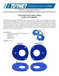
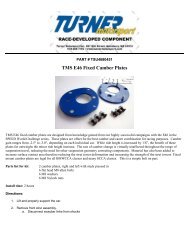
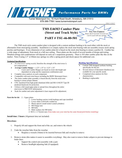
TMS E46M3 Camber Plate<br />
(Street and Track Style)<br />
PART # TSU-46-80-501<br />
Two New Features<br />
Better shock travel for lowered cars<br />
Can be used with race springs<br />
The TMS stock style caster-camber plate is designed with a custom urethane bushing to be used either with the stock or<br />
aftermarket front strut/spring assembly. <strong>Installation</strong> is to simply replace the stock strut bearing with our assembly (reuses stock spring<br />
perches and bearings). Every dimension of our camber plate kit is based on the stock strut bearing to ensure a perfect fit. Camber has<br />
a wide range of adjustment, from stock to a full race setting. These plates are the result of several months of design and testing.<br />
Detailed settings and combinations will depend on each car’s suspension geometry. There is NO other camber plate like this on the<br />
market. Note if using 2.5” or 60mm race springs we offer a spring perch and shock spacer for additional cost.<br />
Technical Specifications<br />
No strut tower cutting needed, therefore the strength of the strut tower is<br />
not compromised.<br />
Average Camber Range ≈ -1.23° ±.33° to -3.23° ±.33°<br />
o<br />
Caster and Camber Ranges are based on stock ride height and<br />
dependent on setup and the suspension combination used<br />
Complete stress analysis on each component.<br />
Compatible with most strut braces including the BMW <strong>Motorsport</strong> brace.<br />
The entire camber plate assembly is based directly from the stock strut<br />
bearing to ensure proper fitment.<br />
CNC machined from high grade aluminum billet and Mil-A-8625F Type III<br />
anodized (hardcoat) for protection.<br />
Utilizes a full round upper plate to spread force throughout the entire<br />
strut tower to PREVENT deformation.<br />
Scale for camber and caster adjustment is laser engraved for adjustment.<br />
Bushing Specifications<br />
Custom TMS designed urethane bushing<br />
specifically for this kit.<br />
Several choices of durometer (hardness) are<br />
available for your specific needs.<br />
Completed stress analysis for flow<br />
characteristics.<br />
Bushing is replaceable.<br />
Parts list for kit: 2 – Upper plates<br />
2 – Lower bushing carriers (with bushings and caps installed)<br />
2 – Lower slides (with bolts welded in)<br />
2 – Shock spacers (small nickel coated cylinders)<br />
6 – M8 Flange nuts<br />
8 – M8 bolts<br />
8 – Slide washers (for M8 bolts)<br />
2- M14 x 1.5 Nylock nuts (Note make sure your strut has the same thread pitch before installing)<br />
Install time: 3 hours (Alignment time not included)<br />
Directions:<br />
1. Properly lift and support the front end of the car, and remove the wheels<br />
2. Undo the swaybar links from the swaybar.<br />
Requires a wrench (16mm) to be inserted between link and swaybar to remove<br />
3. Remove struts (this makes it easier to assemble everything). May also want to remove brake calipers to prevent damage to<br />
brake lines.<br />
Support the control arm assembly with a jack<br />
Remove headlight adjusting link (if equipped)
Loosen the lower shock bolt enough to let the shock body twist (note orientation)<br />
Remove the top strut mount nuts (there are three).<br />
Lower the control arm assembly. Be careful not to damage the brake lines or any other connecting wires/parts, and<br />
pull out the entire strut assembly.<br />
Remove top strut plate by using a spring compressor (if needed) and removing the top shock nut.<br />
4. Assemble camber plates. See pictures below.<br />
Springs should still be on shock and you will reuse the stock washer that sits on the shock chamfer.<br />
Slide the shock spacer onto the shock. The large OD should sit flush against the stock washer.<br />
Place the stock bearing, spring perch (and rubber isolator) onto the TMS camber plates.<br />
Slide entire camber plate assembly over the strut. Make sure the bushing sits on the shock spacer with a little<br />
compression in the spring, and nothing binds up.<br />
Put on M14 washer and shock nut.<br />
Caster can be set at this time. Most people will want maximum caster, with the adjustment placed fully towards the<br />
back of the car.<br />
5. Install Camber plates and shocks<br />
Place the shock shaft into the spindle properly oriented and torque bolt to:<br />
81 N*m (61 ft*lb)<br />
o Note: You can also bolt the strut assembly to the strut tower first and use the jack to line up the spindle and shock.<br />
Raise the control arm assembly up until it’s close to the shock tower.<br />
Make sure the camber plate is properly oriented and raise the control arm assembly up making sure the bolts go all<br />
the way through the shock tower.<br />
Torque M8 flange nuts to: (18 ft*lb).<br />
Hook up the swaybar links<br />
Tip: Do not hook up swaybar links if doing one side at a time. Both sides need to be undone.<br />
6. Alignment: To adjust the caster, the camber bolts must be loose and the plates able to slide back and forth. After caster is set,<br />
Camber can be set.<br />
Adjust the caster so the shock is the farthest back towards the rear of the car possible.<br />
Tighten down the 4 M8 bolts and torque to: 10 ft*lbs (Do not over torque!!!)<br />
Adjust the camber so the shock is leaned the farthest to the outside of the car possible.<br />
Take to alignment shop with your required settings or they will set everything close to stock.<br />
To adjust, the car should have the weight taken off of it to reduce wear and tear and prevent damage to the plates.<br />
2
Adjusting Caster<br />
Loosen the camber nuts (1,2,3). This<br />
allows the Plate to move so each caster<br />
bolt can be accessed.<br />
Loosen the caster bolts (4,5,6,7) by<br />
moving plate back and forth, and adjust to<br />
desired position based on tick marks.<br />
Tighten Caster bolts (do no over tighten!!).<br />
Reset camber settings.<br />
Adjust camber using tick marks and<br />
tighten camber nuts.<br />
Adjusting Camber<br />
Loosen the camber nuts (1,2,3) and slide<br />
plates into desired position. Tighten<br />
Camber bolts. 1<br />
Camber Movement<br />
2<br />
4<br />
5<br />
6 7<br />
Caster Movement<br />
3<br />
Driver Side<br />
Front of car<br />
Note - To adjust the caster while keeping the camber set for fine tuning:<br />
Loosen all the camber nuts (1, 2, 3)<br />
Loosen the caster bolts (4, 5, 6, 7)<br />
Reset the camber for the desired position and tighten camber nuts<br />
Move caster to desired position.<br />
o Tighten down caster bolts that are within the strut tower opening.<br />
Loosen camber nuts, move plate back and forth to tighten the remaining caster bolts<br />
Set the camber to desired position and tighten camber nuts.<br />
Tip – An approximation of 11.5mm of movement along the strut tower can be assumed to be 1 degree of camber change.<br />
This means that if the camber plate does not move in the strut tower slots when adjusted, each ticmark is approximately .5<br />
degrees.<br />
3