Schrick Technical Information / Specs - Turner Motorsport
Schrick Technical Information / Specs - Turner Motorsport
Schrick Technical Information / Specs - Turner Motorsport
- No tags were found...
You also want an ePaper? Increase the reach of your titles
YUMPU automatically turns print PDFs into web optimized ePapers that Google loves.
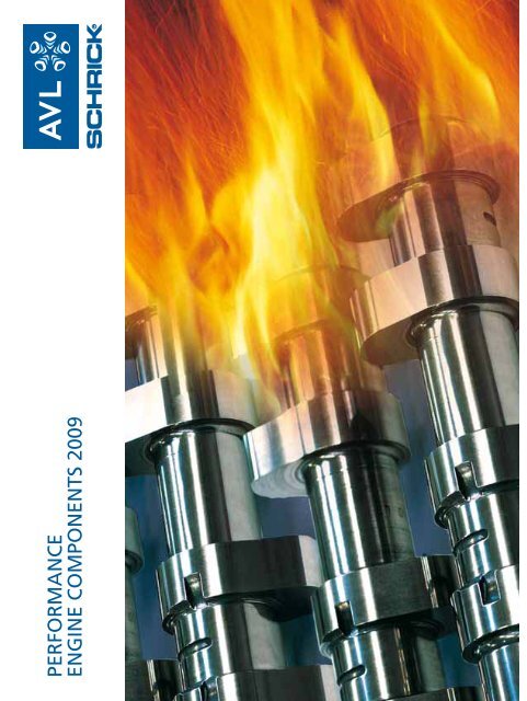
PERFORMANCEENGINE COMPONENTS 2009
Explanation of the catalogTuners and engine builders will find in thiscatalog a selection of the camshafts and otherengine performance parts that we have instock, or can deliver on short notice.What is the difference between a SportandStandard cam-shaft?Standard camshafts offer a good compromisebetween the daily requirerements from anautomotive engine: sustained high speed onopen roads, smooth engine idle at low rpmand low exhaust emissions.If the importance of one or more of theseparameters is reduced, the camshaft can bedesigned to function better in the remainingparameters.Racing camshafts offer a substantial powerincrease at high rpm. Engine idle at low rpm isnot possible anymore.Sport camshafts inrease the valve lift, valveopening duration and the inlet/outlet valveoverlap. This improves the cylinder filling athigh rpm.Engine idle at low rpm becomes erratic, due tothe mixing of intake air and exhaust gasses.Why are SCHRICK camshafts so special ? They are manufactured by highly qualifiedspecialists, who also supply the automotiveindustry. They are machined to precise tolerances,using the latest CNC machines. They are usually made from expensive, extremelywearresistant “chilled” cast-iron. Warranty: 1 year without kilometer limitation.Which camshafts are good for Streettuning?If the vehicle is intended for normal street use,i.e. with a stable engine idle and the abilityto pass an emissions test (idle to lower rpmrange), it is important to consider a small valvelift at TDC.The table gives a gudeline for valve lift at TDC.2 Valve engineswith solid lifters4 Valve engineswith solid lifters2 Valve engineswith hydraulic lifters4 Valve engineswith hydraulic lifters2.3 mm1.5 mm1.9 mm1.1 mmWhen these values are exceeded, the engineidle will become increasingly unstable and thetorque delivery in the lower rpm range will benoticably weaker.Camshafts with larger valve durations, and aresulting higher valve lift at TDC, should onlybe considered for racing applications, or wheneach cylinder has it`s own butterfly valve i.e. 2twin-choke carburettors on a 4 cylinder engine.We have to point out that technical changes toan engine voids the vehicle`s type approval.What precaution must be taken withvalve springs ?When we recommend the use of special valvesprings, it is advisable to do so. SCHRICK camshaftsusually have an increased valve lift. If thestandard valve springs are used, it is importantto increase the spring`s installedheight, so that the increased lift will not overlycompress the valve springs (possibly causingspring breakage or unacceptable cam/followerloads).When we do not list your requiredcamshaft ?We have several possibilities to help you:1. We grind your required profile ona camshaft blank. The machineset-up cost will be added to theprice of a comparable camshaft.2. We can machine a camshaft frombillet steel (single piece or smallbatchproduction). We would beglad to help and advise you onyour specific application.Explaining the listed technical dataValve timing and valve opening durations areshown minus the ramps.Valve timing is shown as IO (Inlet opens in°Crankshaft before TDC), IC (Inlet closes in°Crankshafts after BDC), EO (Exhaust opens in°Crankshafts before BDC) and EC (Exhaust closesin °Crankshafts after TDC).Peak timing is shown as °Crankshaft and definesthe angle between the gas exchange TDCand the lobe center line of the inlet- or exhaustvalves.All valve lift figures are shown without deductionof valve lash, i.e. the actual valve lift is thestated valve lift minus the valve lash.Since engines with hydraulic lifters have novalve lash, the stated valve lift is also the actualvalve lift.Valve lift at TDC is also shown without deductionof valve lash, i.e. the actual valve lift atTDC is the stated lift minus the valve lash.The graph shows the valve opening durationand valve lift curve for Standard- and Sportcamshafts. It also shows the important differencesin inlet/exhaust valve overlap and valvelift at TDC.General noteAll products in this catalog (except advertisingmaterial) are only available through the automotorstrade.This catalog supersedes all previous catalogs.Part specifications and prices subject to change.We may change technical specifications of ourproducts without notice. Shipments back to uswill only be accepted if we agreed before andin suitable, protective packaging. We will creditthe invoiced amount -15% referring to thevalid catalog price. Products which reach us willnot be accepted if they were modified or havedamages. This catalog is valid from 01.01.20092
Camshafts Audi 5 Cyl. 4 Valve CALL TMS Fo BMW M10 4 Cyl. 2 Valve CALL TMS 0002 02 080 upper 0002 13 059 0002 02 043 key 0894 13 8M8 0002 02 080 upper 0002 13 059 0002 02 043 key 0894 13 8M8 0002 02 080 upper 0002 13 059 Fi0002 02 043 key 0894 13 8M8 0002 02 080 upper 0002 13 059 0002 02 043 key 0894 13 8M8 BMW M20 6 Cyl. 2 Valve BMW M30 6 Cyl. 2 Valve
Camshafts BMW S14 4 Cyl. 4 Valve 0227 02 113 upper 0227 13 055 lower 0227 13 058 key 0894 13 8L7 tappet 0227 13 805 int. valve 0227 13 053 exh. valve 0227 13 054 0227 02 113 upper 0227 13 055 lower 0227 13 058 key 0894 13 8L7 tappet 0227 13 805 int. valve 0227 13 053 exh. valve 0227 13 054BMW S50, S52 6 Cyl. 4 Valve M3 M VVanos 0227 02 113 tappet 0227 13 805 upper ret. 0284 13 012 lower ret. 0284 13 013 key 0894 13 8L6 valve 0284 13 014 intake 0227 02 113 tappet 0227 13 805 upper ret. 0284 13 012 lower ret. 0284 13 013 key 0894 13 8L6 valve 0284 13 015 exhaustBMW M88, S38 6 Cyl. 4 Valve
Camshafts BMW S54 rocker arm 0415 13 800 CALL TMS rocker arm 0415 13 800 CALL TMS rocker arm 0415 13 800 CALL TMS rocker arm 0415 13 800 CALL TMS rocker arm 0415 13 800 CALL TMS rocker arm 0415 13 800 CALL TMS 0415 02 095 rocker arm 0415 13 800 CALL TMS Retainer up 0415 13 011 & lo -012 0415 02 095 rocker arm 0415 13 800 CALL TMS Retainer up 0415 13 011 & lo-012 0415 02 095 rocker arm 0415 13 800 CALL TMS Retainer up 0415 13 011 & lo -012 0415 02 095 CALL TMS BMW S62 V8 Cyl. 4 Valve CALL TMS CALL TMS CALL TMS CALL TMS BMW S85, 10 Zyl. 4V CALL TMS CALL TMS CALL TMS CALL TMS CALL TMS CALL TMS CALL TMS CALL TMS BMW R 259 2 Cyl. 4 Valve Boxer CALL TMS
Camshafts BMW F650 1 Cyl. 4 Valve BMW S65 V8 4Valve M3 E92 CALL TMS Chrysler PT Cruiser 4 Cyl. 4 valve CALL TMS Ducati V 2 Cyl. 2 Valve CALL TMS Ducati V 2 Cyl. 4 Valve CALL TMS Fiat 20V 5 Cyl. 4 Valve CALL TMS Ford CVH 4 Cyl. 2 Valve Aluminium Cylinder Head
Camshafts Mini 4Cyl. 4V Cooper S R56 N14 11/2005- CALL TMS CALL TMS Mini 4 Cyl. 4 valve CALL TMS CALL TMS Moto Guzzi 2 Cyl. 2 Valve Nissan 350Z V6 Cyl. 4 Vent. Opel OHC 4 Cyl. 2 Valve Aluminium Cyl. Head, Big Block Opel 16 V Ecotec 4 Cyl. 4 Valve Opel 4 Cyl. 4 Valve roller cam follower 0242 02 054 upper 0412 13 004 0242 02 019 lower 0895 00 820key 0894 13 8M6 0242 02 054 upper 0412 13 004 0242 02 019 lower 0895 00 820key 0894 13 8M6
Camshafts Suzuki 4Cyl. 4V 1,4-1,8L SWIFT, IGNIS Camshaft Kits Audi 5 Cyl. 2 Valve Audi 4 Cyl. 5 Valve BMW M20 6 Cyl. 2 Valve CALL TMS
Camshaft Kits BMW S14 4 Cyl. 4 Valve CALL TMS CALL TMS CALL TMS BMW S50, S52 6 Cyl. 4 Valve CALL TMS BMW S50, S52 6 Cyl. 4 Valve CALL TMS BMW S54 CALL TMS CALL TMS Ford Zetec SE 4 Cyl. 4 Valve Opel OHC 4 Cyl. 2 Valve Aluminium Cyl. Head, Small Block
Valves Valve keys
Valve blanksStem ground, Head premachined, without key grovesPricePriced [mm] D [mm] L [mm] EUR / ea. Discount d [mm] D [mm] L [mm] EUR / ea. DiscountPart No. Stem dia. Head dia. Length excl. VAT group Part No. Stem dia. Head dia. Length excl. VAT groupBimetall - Steel, for intake and exhaust up to appr. 70 KW / lBimetall - Nimonic , for exhaust, when more then appr. 70 KW / l0894 50 30S 4,98 30 124 30894 55 30S 5,48 30 124 30894 60 30S 5,98 30 139 30894 70 30S 6,98 30 139 30894 80 30S 7,98 30 139 30894 50 34S 4,98 34 124 30894 55 34S 5,48 34 124 30894 60 34S 5,98 34 139 30894 70 34S 6,98 34 139 30894 80 34S 7,98 34 139 30894 50 38S 4,98 38 124 30894 55 38S 5,48 38 124 30894 60 38S 5,98 38 139 30894 70 38S 6,98 38 139 30894 80 38S 7,98 38 139 30894 55 41S 5,48 41 124 30894 60 41S 5,98 41 139 30894 70 41S 6,98 41 139 30894 80 41S 7,98 41 139 30894 60 45S 5,98 45 139 30894 70 45S 6,98 45 139 30894 80 45S 7,98 45 139 30894 70 50S 6,98 50 139 30894 80 50S 7,98 50 139 30894 80 53S 7,98 53 139 30894 50 30N0894 55 30N0894 60 30N0894 70 30N0894 13 0950894 50 34N0894 55 34N0894 60 34N0894 70 34N0894 80 34N0894 55 38N0894 60 38N0894 70 38N0894 80 38N0894 70 41N0894 80 41N0894 70 45N0894 80 45N0894 13 1010894 80 50N4,985,485,986,987,984,985,485,986,987,985,485,986,987,986,987,986,987,986,987,98303030303034343434343838383841414545505012412413913913912412413913913912413913913913913913913913913933333333333333333333Valve Spring RetainersPriceEUR / ea.d1 d2 h s Type, spring excl. DiscountPart No. [mm] [mm] [mm] [mm] keys material reference VAT group Remarks0005 13 035 31,4 22,6 -1,0 3,9 lower, steel 0013 02 064 & 031 2 - 120005 13 036 23,6 17,0 3,0 10° RK8 upper, titanium 0013 02 064 & 031 2 - 120894 13 8R80005 13 041 23,61 17,0 3,0 14,25° MK8 upper, titanium 0013 02 064 & 031 2 - 1 2 Porsche Carrera (993)0894 13 8M8 0005 13 001/002 valves0005 13 035 043 lower retainer0005 13 042 23,6 17,0 3,0 14,25° MK9 upper, titanium 0013 02 064 & 031 2 - 12 Porsche Carrera 2 40005 13 035 lower retainer0005 13 043 3,3 lower, steel 2 - 12lower retainer0014 13 094 22,5 16,0 2,0 1,0 lower, steel 0013 02 062 & 026 2 - 80014 13 194 23,0 16,3 2,0 14,25° MK8 upper, titanium 0013 02 062 & 026 2 - 80894 13 8M80014 13 195 23,0 16,3 2,0 10° RK8 upper, titanium 0013 02 062 & 026 2 - 80894 13 8R80014 13 198 22,4 16,6 2,2 14,25° MK7 upper, titanium 0014 02 054 & 027 2 - 80894 13 8M70014 13 199 22,4 16,6 2,2 1,5 lower, steel 0014 02 054 & 027 2 - 80050 13 126 23,3 16,6 1,0 1,0 lower, steel 0013 02 064 & 031 2 - 80050 13 133 23,3 16,7 1,0 10° RK8 upper, steel 0013 02 064 & 031 2 - 80894 13 8R80050 13 325 23,6 17,0 1,0 14,25° MK8 upper, steel 0013 02 064 & 031 2 - 80894 13 8M80220 13 133 23,6 17,4 2,0 10° RK7 upper, titanium 0013 02 064 2 - 160894 13 8R7 0220 02 0260220 02 1030220 13 134 23,6 17,4 2,0 14,25° MK7 upper, titanium 0013 02 064 2 - 160894 13 8M7 0220 02 0260220 13 135 23,6 17,4 2,0 1,5 lower, steel 0013 02 064 2 - 160220 02 0260220 13 144 23,6 17,4 2,0 lower, steel 0220 02 103 2 - 16 with upper retainer 0220 13 1330227 13 051 23,6 17,4 2,0 14,25° MK7 upper, titanium 0013 02 064 2 - 160894 13 8M7 0220 02 0260227 13 052 23,6 17,4 2,0 2,0 lower, steel 0013 02 064 2 - 160220 02 0260227 13 055 22,8 16,6 2,0 14,25° LK7 upper, titanium 0227 02 113 2 - 160894 13 8L70227 13 058 16,6 1,0 lower, steel 0227 02 113 2 - 160227 13 057 23,6 17,4 2,0 14,25° LK6 upper, titanium 0013 02 064 2 - 160894 13 8L6 0220 02 02625
Valve Spring Retainers Valve lash caps
Valve Springs Washers for valve springs Timing gears and accessories
Cam followers Special Products CALL TMS E36 ,,E34/E39
Nockenwelleneinbau /Camshaft installation
vermeiden. Sind die Lagerstellen im Zylinderkopfmaßhaltig, ist die Lageroberfläche unbeschädigt?Sollten die Lagerstellen nicht einwandfrei sein, wird vondem Einbau der <strong>Schrick</strong> Nockenwelle abgeraten. Lässtdie <strong>Schrick</strong> Nockenwelle sich im Zylinderkopf frei drehenoder stößt ein Nocken am Guss an (Siehe Bild 6)? Die<strong>Schrick</strong> Nockenwelle darf mit keinem Bauteil kollidieren.Es muss sichergestellt werden, dass keine beweglichenTeile miteinander kollidieren. <strong>Schrick</strong> Nockenwellenhaben meist eine größere Auswanderung auf demNockenfolger da die Nockenkontur von der Serie abweicht.Ist die Lauffläche der Nockenfolger genügendgroß (Stößeldurchmesser; beim Hebel Laufflächenlänge )?Die Nockenfolger müssen in einwandfreiem Zustandsein. (Stößel,Kipphebel,Schlepphebel ...) Zur Sicherheitsollten sie immer erneuert werden, da schadhafteNockenfolger Motorschäden verursachen. Garantiebesteht nur bei Verwendung neuer Nockenfolger.Während des Einbaus der <strong>Schrick</strong> Nockenwellen mussder Ventilhub in OT am Einlass- und A uslassventilgemessen werden. Stimmt er mit den Katalog - Angabenüberein? (Siehe Bild 2) Wie groß ist die Fallhöhe derVentile bis auf den Kolben (Siehe Bild 3), wenn derKolben in OT steht? Die Fallhöhe muss min. 1,5mmgrößer sein, als der gemessene Ventilhub in OT (SieheBild 2 ) der <strong>Schrick</strong> Nockenwellen. Es muss sichergestelltwerden, dass bei max. Überschneidungshub die Einlassund A uslass Ventilteller sich nicht berühren können(min. 1,5mm Abstand). Der obere Ventilfederteller mussbei max. Ventilhub min 1,5mm Abstand zur Ventilschaftdichtunghaben. Bei welchem Ventilhub ist dieFeder ganz zusammengedrückt (auf Block) (Siehe Bild4)? Die Ventilfeder muss bei max. Ventilhub min. 1,0mmFederweg Reserve haben. Zur Kontrolle ist es nichtausreichend den Motor von Hand durchzudrehen, esmüssen die A bstände gemessen werden. A ufgrund derElastizität der Bauteile kann ein Motor trotz blockierenderBauteile von Hand durchgedreht werden.Are the Cylinder head bearing dimensions within thefactory tolerances and the bearing surfaces free of anydamage?If there is any doubt that your cylinder head is notwithin service limits, the installation must be aborted!Does the <strong>Schrick</strong> camshaft have enough clearance toturn freely in the cylinder head or do the cams or otherparts collide with the cylinder head (Illustration 6)? Thecamshaft and all other moving parts must not collidewith any other part.Is the cam follower contact surface large enough (tappetdiameter, rocker arm length) to handle the loadsproduced by the additional cam lift and duration?All cam followers (tappets or rocker arms etc.) must bein near-new condition with little evidence of any sortof damage (spalling, scratches, etc.). We highly recommendthe installation of new cam followers with yourcamshaft to avoid damage to the camshaft, cylinderhead, and/or your engine.During the installation, the valve lift at TDC (Illustration2) must be measured for both the intake and exhaustvalve. Check to determine if the measured valve lift atTDC corresponds with the published catalog information?Determine how much clearance is available betweenthe valve and piston (Illustration 3), in the TDC position?The remaining clearance must be min. 1.5mm largerthan the measured valve lift at TDC (Illustration 2 ) ofthe <strong>Schrick</strong> camshaft in your installation. You must beassured that the valves and pistons at maximum valvelift at TDC have a remaining clearance which is greaterthan 1.5mm! Also you must be assured that the intakeand exhaust valves do not collide under the maximumvalve lift condition at TDC!At maximum valve lift, the upper valve spring retainerand valve keys must have min 1.5mm clearance to thevalve stem seal. What is the maximum valve lift beforethe valve spring is at block length (Illustration 4)? Atmaximum valve lift all valve springs must have a remainingspring travel larger than 1.0mm.Note: It is not a sufficient to turn over the engineby hand. All clearances must be measured!3
Winkelorientierung der<strong>Schrick</strong> Nockenwelle zurKurbelwelleHow to ensure correctCamshaft Timing.Die richtige Winkelorientierung kann meistens mitder Serieneinbauvorschrift erreicht werden. Da jedochdie Nockenkonturen und die Winkel nicht der Seriennockenwelleentsprechen muss die richtige Winkelpositionanhand der gemessenen Ventilhübe in OTsichergestellt werden.Falls keine Einbauvorschrift der Hersteller mehr verfügbarist, nachfolgend ein Beispiel wie man grundsätzlicheine Nockenwelle einstellt:Die Kurbelwelle drehen, bis die Kolben auf halbem Hubvor dem oberen Totpunkt stehen. Die NW und dieNockenfolger ausreichend mit Motorenöl benetzen.Nockenfolger und Nockenwellen einlegen und dieLagerbrücken gleichmäßig anziehen bis alle Lagerbrückenaufliegen, werden die Lagerbrückenungleichmäßig angezogen kann die Nockenwellebrechen! Abschließend die Schrauben mit einemDrehmomentschlüssel nachziehen. Die Nockenwelle aufden richtigen Überschneidungshub einstellen undfixieren. In Motordrehrichtung geht das Einlass-Ventilgerade auf und ist schon um den Überschneidungshuboffen. In Motordrehrichtung geht das Auslass-Ventilgerade zu und ist noch um den Überschneidungshuboffen. Die Kurbelwelle drehen, bis der Kolben der aufÜberschneidung stehenden Ventile auf dem oberenTotpunkt ist und fixieren. Die Kurbelwelle darf nichtüber OT hinaus gedreht werden. Den Nockenwellenantriebmontieren, die Fixierungen lösen und denAntrieb spannen. Die Kurbelwelle 720 Grad (zwei Umdrehungen)drehen und die Überschneidungshübe amEinlass- und A uslassventil erneut nachmessen, sind dieWerte unverändert ist die Nockenwelle im richtigenWinkel zur Kurbelwelle montiert. Die Begriffe und diezugehörigen Zahlenwerte entnehmen Sie bitte denBildern 1...6.The angular adjustment of <strong>Schrick</strong> camshafts is in mostapplications the same as for standard camshafts. However,as the cam profiles are different and the angularposition of the cams on the camshaft may be differentto standard parts you must measure the valve lift atTDC to ensure the correct angular position. During anycamshaft installation the valve-piston and valve-valveclearances must be measured, the valve springs must bechecked to have sufficient clearance at maximum valvelift, and the camshaft should be observed to turn freelyas depicted in section 1 (illustrations 3;4;6 )?After the above information is determined and recordedand if no installation instructions from the engine manufacturerare available, the following points are to beobserved: Turn the crankshaft to an angle where themajority of pistons are as far away from TDC as possible.Oil all of the surfaces of your newly cleaned cam followersand camshafts. Put the cam followers and the camshaftsinto the cylinder head and tighten the bearing capscrews smoothly with constant force until all bearingcaps have reached their seat. Be aware that uneventightening or torque sequence may cause brokencamshafts. Finally, all bearing cap screws must be tightenedwith a torque wrench to the specified torque. Nowindex the camshaft to the angular position until thevalves are opened to the specified valve overlap-lift atTDC and fix it. This means: In running direction of theengine the intake valve has started to open and isopened the specified overlap-lift at TDC. In runningdirection of the engine the exhaust valve has started toclose and is still opened the specified overlap-lift atTDC. The next step is to index the crankshaft until thepiston on the timing cylinder (usually #1) is at TDC. Onthis cylinder, the valves should be on overlap and themechanic should fix the crankshaft. Assemble the pulley4
and chain/belt, remove camshaft and crankshaft fixingand tighten the belt/chain. Turn the crankshaft 720degrees and measure the overlap-lift at TDC once more.When the measured lifts match the specifications; thecamshaft has the correct angular position in relation tothe crankshaft.Ventilfedern, was mussbeachtet werden?Die Ventilfeder muss bei max. Ventilhub min. 1,0mmRestweg zu Verfügung haben. Die Einbaulänge von<strong>Schrick</strong> Ventilfedern muss den Angaben im <strong>Schrick</strong>Katalog entsprechen, und muss auf die richtige Einbaulängeeingestellt werden. Zum Beispiel durch unterlegenvon Scheiben oder abdrehen des unteren Ventilfedertellers.Die Federn müssen oben und unten Radial gut geführtwerden, um Schwingungen und Verschleiß gering zuhalten, nur so erreicht die Feder eine lange Lebensdauer.Bei Verwendung unserer Nockenwellen Bausätze mitoberen und unteren Federtellern, wird die richtigeFedereinbaulänge im Normalfall ohne Nacharbeiterreicht. Zur Sicherheit muss die Federeinbaulängenachgemessen werden. Die Ventilfederkräfte müssenauf den Einsatzzweck abgestimmt sein. Die Kraft darfweder zu hoch noch zu niedrig sein, beides führt zuMotorschäden!Valve springs; what do I haveto pay specific attention to?All valve springs must have minimum 1mmclearance before ”coil bind” length at maximumvalve lift!The installed height of <strong>Schrick</strong> valve springs must beadjusted according to the <strong>Schrick</strong> specifications. Additionally,the installed height must be measured andindividually adjusted at each valve and for each installation.Example: The adjustment may be done by usingwashers as shims or by machining the lower valve springretainer.The valve spring forces must be calculated for yourindividual application. Engine damage may result if thespring forces in your engine are to low or to high. Thesprings must be guided properly on both ends to reducevibrations. Only springs which are properly installed andguided will be durable.When complete camshaft kits including valve springsand valve spring retainers from <strong>Schrick</strong> are available foryour engine, we highly recommend using them becausesprings, retainers and camshafts are designed to secureproper lengths and guidance together with calculatedspring forces for this application. You need to measurethe clearance during assembly to verify that everythingis within the <strong>Schrick</strong> specifications.5
Was ist die Spreizung an einerNockenwelle?Unter Auslass Spreizung (AM) versteht man:Den Winkelabstand, gegen die Drehrichtung, derKurbelwelle vom oberen Totpunkt des Kolbens biszum max. Auslassventilhub.Unter Einlass Spreizung (EM) versteht man:Den Winkelabstand, in Drehrichtung, der Kurbelwellevom oberen Totpunkt des Kolbens bis zum max.Einlassventilhub.What does spread angle meanon camshafts?The exhaust spread angle (EM) is to be understoodas: The angle between overlap TDC and max. exhaustvalve lift reverse to crankshaft rotating direction.The intake spread angle (IM) is to be understood as:The angle between overlap TDC and max. intakevalve lift in crankshaft rotating direction.Bild 1Illustration 1AuslassExhaustEinlassIntakeAuslassExhaustEinlassIntakeMax HubMax LiftMaxVentilhubAuslassMaxExhaustvalve LiftMaxVentilhubEinlassMaxIntakevalve LiftMax HubMax Lift110°110°AuslassSpreizungExhaustspreadangleEinlassSpreizungintakespreadangle6
Was ist dieVentilüberschneidung?In Motordrehrichtung geht das Einlass-Ventil geradeauf und ist schon um den Überschneidungshub geöffnet.In Motordrehrichtung geht das Auslass-Ventil geradezu und ist noch um den Überschneidungshub geöffnet.Es muss weiterhin sichergestellt werden, dass bei max.Überschneidungshub die Einlass- und A uslassventiltellersich nicht berühren können min 1,5mm Abstand( Maß X ).What does valve lift at TDCor overlap valve lift mean?In crankshaft rotating direction the intake valve hasstarted to open and is already opened the amount calledvalve lift at TDC or overlap.In crankshaft rotating direction the exhaust valve hasstarted to close and is still opened the amount calledvalve lift at TDC or overlap.ÜberschneidungsOT Einlass undA uslass Ventil istgeöffnetoverlap TDCIntake and Exhaustvalve are openAuslassExhaustEinlassIntakegeöffnetopenMin 1,5mmgeöffnetopenMin 1,5mmBild 2Illustration 2geöffnetopenMin 1,5mmgeöffnetopenMin 1,5mm7
Was ist die Ventil-Fallhöhe?Unter Ventil-Fallhöhe versteht man den Abstand derVentile vom geschlossenen Ventil im Sitz, bis zum Kontaktdes Ventils mit dem Kolben, wenn der Kolben in OTsteht.Die Fallhöhe muss min. 1,5mm größer sein, als dergemessene Überschneidungshub der Nockenwellen.What is the drop heightbetween valve and piston atTDC?The drop height between valve and piston is the distancethe valve is able to move starting from the valve seatuntil it touches the piston at TDC.This drop height must be at least 1.5mm greater thanthe specified valve lift at TDC produced by the desiredcamshafts. In some applications it is necessary to millvalve pockets into your pistons to get the right dropheight.Additionally, it must be ensured that at maximum valvelift (at TDC) the valve heads cannot contact each otherand have min 1.5mm distance remaining.Bild 3Illustration 3AuslassExhaustEinlassIntakeVentilfallDrop HeightVentilfallDrop Height8
Ventilfeder EinbaulängenWhat is the installed heightof valve springs?Die Ventilfeder muss bei max. Ventilhub min. 1,0mmRestweg zu Verfügung haben.Die Einbaulänge der <strong>Schrick</strong> Federn muss den Angabenim <strong>Schrick</strong> Katalog entsprechen, ist sie abweichendmuss die Länge richtig eingestellt werden. Zum Beispieldurch unterlegen von Scheiben, oder abdrehen desunteren Tellers.The valve spring must have a remaining clearance thatexceeds 1mm at maximum valve lift.The installed height must be according to <strong>Schrick</strong> specifications.If the installed height differs, it must beadjusted with washers (shims) or by machining the lowerretainer.Bild 4Illustration 4richtig / rightfalsch / wrongL2L2Max HubMax LiftMax HubMax Liftrichtige Federeinbaulänge bei max. Ventilhub hat dieFeder noch min 1mm Restwegright installed height at max. valve lift the spring hasstill min. 1mm clearance remaining before coil bindfalsche Federeinbaulänge bei max. Ventilhub hat dieFeder keinen möglichen Restweg mehrwrong installed height at max. valve lift the spring hasno more clearance left all coils are blocked9
Freigängigkeit derNockenwelle<strong>Schrick</strong> Nockenwellen haben meist einen größerenNockenhub. Daraus ergibt sich ein größerer Umlaufradiusder Nockenspitze. Es muss sichergestellt werden, dassgenügend Freigängigkeit vorhanden ist, und dieNockenwelle an keiner Stelle mit anderen Bauteilenkollidiert.What does freedom ofmotion mean for camshafts?<strong>Schrick</strong> camshafts typically have more cam lift thanstandard parts. This means that <strong>Schrick</strong> camshafts needmore clearance space to rotate without contact. It mustbe ensured that the cams cannot collide with any otherpart when the camshaft is turning.Bild 6Illustration 6Alle Angaben und Werte ohne Gewähr.Bitte verwenden Sie nur die Werte, die für IhreAnwendung/Applikation geeignet sind.All mentioned reference values are generalreference values without guarantee.Please use only the specific reference valuesfor your application.11
Dr. SCHRICK GmbH I Dreherstraße 3-5 I D-42899 Remscheid I Tel. +49 21 91/9 50-0 I Fax +49 21 91/9 50-1 15 I www.schrick.comSTITZ+BETZ GmbH · Dortmund · Berlin


