Random Access Heterogeneous MIMO Networks - NMS Lab
Random Access Heterogeneous MIMO Networks - NMS Lab
Random Access Heterogeneous MIMO Networks - NMS Lab

You also want an ePaper? Increase the reach of your titles
YUMPU automatically turns print PDFs into web optimized ePapers that Google loves.
<strong>Random</strong> <strong>Access</strong> <strong>Heterogeneous</strong> <strong>MIMO</strong> <strong>Networks</strong><br />
Kate Ching-Ju Lin<br />
Academia Sinica<br />
katelin@citi.sinica.edu.tw<br />
Shyamnath Gollakota<br />
MIT<br />
gshyam@csail.mit.edu<br />
Dina Katabi<br />
MIT<br />
dk@mit.edu<br />
ABSTRACT<br />
This paper presents the design and implementation of 802.11n + ,<br />
a fully distributed random access protocol for <strong>MIMO</strong> networks.<br />
802.11n + allows nodes that differ in the number of antennas to<br />
contend not just for time, but also for the degrees of freedom provided<br />
by multiple antennas. We show that even when the medium<br />
is already occupied by some nodes, nodes with more antennas<br />
can transmit concurrently without harming the ongoing transmissions.<br />
Furthermore, such nodes can contend for the medium in a<br />
fully distributed way. Our testbed evaluation shows that even for a<br />
small network with three competing node pairs, the resulting system<br />
about doubles the average network throughput. It also maintains<br />
the random access nature of today’s 802.11n networks.<br />
Categories and Subject Descriptors C.2.2 [Computer<br />
Systems Organization]: Computer-Communications <strong>Networks</strong><br />
GeneralTerms Algorithms, Design, Performance, Theory<br />
Keywords <strong>MIMO</strong>, Interference Alignment, Interference<br />
Nulling<br />
1. INTRODUCTION<br />
Multi-Input Multi-Output (<strong>MIMO</strong>) technology [6] is emerging<br />
as the default choice for wireless networks. The wireless industry<br />
is continuously pushing toward increasing the number of antennas<br />
per device. While 3 × 3 <strong>MIMO</strong> nodes represented the state of the<br />
art in 2009, 4 × 4 <strong>MIMO</strong> nodes were introduced on the market in<br />
2010 [1]. Simultaneously, there is a proliferation of wireless devices<br />
with diverse form factors. These range from large devices,<br />
likedesktopsandlaptops,tosmalldevices,liketemperatureorlight<br />
sensors, and awhole range of devices inbetweenlike smartphones<br />
and tablets. The physical size of these devices intrinsically limits<br />
the maximum number of antennas that they can support, and their<br />
differing capabilities and costs mean that they will naturally have<br />
different <strong>MIMO</strong> processing power. The combination of these two<br />
trends - a growth in the maximum number of antennas per device,<br />
andanincreaseindevicediversity-meansthatfuturewirelessnetworks<br />
will be populated by heterogeneous APs and clients supporting<br />
different numbers of antennas. For example, today a home<br />
Permission to make digital or hard copies of all or part of this work for<br />
personal or classroom use is granted without fee provided that copies are<br />
not made or distributed for profit or commercial advantage and that copies<br />
bear this notice and the full citation on the firstpage. Tocopy otherwise, to<br />
republish, topostonserversortoredistribute tolists,requires priorspecific<br />
permission and/or afee.<br />
SIGCOMM’11, August 15–19, 2011, Toronto, Ontario, Canada.<br />
Copyright 2011 ACM 978-1-4503-0797-0/11/08 ...$10.00.<br />
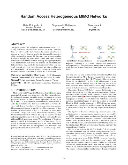
(a) 802.11n’s CurrentBehavior<br />
(b)Desirable Behavior<br />
Figure 1—Currently a 2 × 2 <strong>MIMO</strong> abstains from transmission<br />
in the presence of a single-antenna transmission as shown in (a),<br />
whileitshouldbeabletoconcurrentlyexchange apacket asshown<br />
in(b).<br />
user may have a 2- or 3-antenna AP but one of her neighbors may<br />
haveasingle-antennaAPonthesamechannel.Eveninsideasingle<br />
house, users can connect their HD TV to their video server using<br />
high-end4×4<strong>MIMO</strong>802.11ndevices[1],whilecontinuingtouse<br />
their 2- or 3- antenna wireless AP for the remaining devices in the<br />
home, while the home sensor network uses a single-antenna home<br />
controller that communicates withthe sensors andactuators.<br />
Theexistingdesignof802.11nhoweverusestheblueprintoftraditional<br />
single-antenna networks, and as a result cannot efficiently<br />
support such heterogeneous <strong>MIMO</strong> networks. Consider for examplethescenarioinFig.1(a)whereasingle-antennapairisexchangingapacket.Anearby2<br />
×2802.11nsystemwillabstainfromconcurrently<br />
transmitting because it senses the medium as occupied.<br />
However, this is wasteful because a 2 ×2<strong>MIMO</strong> pair can support<br />
twoconcurrent transmissions,andhence shouldbeabletotransmit<br />
a packet concurrently with the ongoing single-antenna transmission.<br />
Theobjective ofthispaper istodevelop a medium access protocol<br />
that enables as many concurrent transmissions as permitted by<br />
the <strong>MIMO</strong> transmitter withthe maximum number of antennas. We<br />
would like for our design however tomaintain the fullydistributed<br />
random access nature of today’s 802.11n. A distributed protocol<br />
will enable <strong>MIMO</strong> LANs to continue to support bursty traffic and<br />
have independent different networks share the same medium without<br />
explicit coordination.<br />
Werefertoourdesignas802.11n + orsimplyn + .Itallowsnodes<br />
tocontendnotjustfortime,butalsoforthedegreesoffreedom(i.e.,<br />
concurrent transmissions) enabled by multiple antennas. Specifically,<br />
like 802.11, in n + , nodes who have traffic contend for the<br />
medium using carrier sense. Unlike 802.11, however, which stops<br />
contending after a node wins the contention, in n + , nodes with<br />
more antennas thanthecontention winnercontinue tocarriersense<br />
andcontendforthemedium.Onceanodewinsthissecondarycontention,itcantransmitconcurrentlywiththeongoingtransmission.<br />
Theprocess continuesuntilthenumberofuseddegreesoffreedom<br />
146
equalsthemaximumnumberofantennasonany<strong>MIMO</strong>transmitter<br />
withtrafficdemands.<br />
To realize the above design, n + has to address two main challenges:<br />
(a) How do nodes carrier sense in the presence of ongoing<br />
transmissions? n + extends carrier sense to work in the presence<br />
of ongoing transmissions. Specifically, since nodes with multiple<br />
antennas receive the signal in a multi-dimensional space, they can<br />
project on a space orthogonal to the ongoing transmission(s). This<br />
orthogonal space does not contain any interference from the ongoing<br />
signal(s). Nodes can hence contend for concurrent transmissionsinthisorthogonal<br />
spaceasiftheywerecontendingforanidle<br />
medium. Wename thistechnique multi-dimensional carrier sense.<br />
(b) How can a nodetransmit withoutinterferingwith ongoing<br />
transmissions? We use interference nulling [32] to zero out the<br />
signal at the receivers of the ongoing transmissions. For example,<br />
in the scenario in Fig. 1(b), the two-antenna transmitter, tx2, nulls<br />
itssignalatrx1andhencedoesnotinterferewiththeongoingtransmission.<br />
Interference nulling on its own, however, does not allow<br />
nodes toachieveallthedegreesoffreedomavailableinthesystem.<br />
Specifically, consider a scenario where two transmitter-receiver<br />
pairsarealreadyoccupyingthemedium.tx1-rx1isasingle-antenna<br />
pair, while tx2-rx2 is a two-antenna <strong>MIMO</strong> system. Say that a 3-<br />
antenna transmitter-receiver pair, tx3-rx3, wants to transmit concurrently.<br />
Then tx3 will need to zero out its signal on three antennas,<br />
the antenna on rx1 and the two antennas on rx2. Since nulling<br />
requires a node to give up one of its antennas for every receive antenna<br />
where it wants to null its signal [7], it consumes the three<br />
antennas at tx3, leaving it no antenna to transmit to its own receiver.<br />
We will show in §2 that by using a combination of interferencenullingandinterferencealignment,tx3canindeedtransmit<br />
concurrently with tx1 and tx2 and use all the available degrees of<br />
freedom, without interferingwiththe ongoing transmissions.<br />
Our work is mostly related to recent empirical work on <strong>MIMO</strong><br />
systems including [7, 31, 13]. n + is motivated by this work and<br />
buildsonit.Pastsystemshoweverrequireconcurrenttransmissions<br />
to be coordinated by a single node. Concurrent transmissions have<br />
to be pre-coded together at a single transmitter (as in beamforming<br />
[7]) or decoded together at a single receiver (as in SAM [31]),<br />
or the transmitters or the receivers have to be controlled over the<br />
Ethernet by a single master node (as in IAC [13]). In contrast, n +<br />
isafullydistributedmediumaccessprotocolwherenodeswithany<br />
number of antennas can transmit and receive concurrent packets<br />
without a centralized coordinator.<br />
We have built a prototype of n + using the USRP2 radio platform<br />
and evaluated itover a10 MHz channel. Our implementation<br />
uses an OFDM PHY-layer and supports the various modulations<br />
(BPSK,4-64 QAM) and coding options used in 802.11. It alsoaddresses<br />
practical issues like multipathand frequency and timesynchronization.<br />
Our evaluation considers three contending pairs of nodes that<br />
differ in the number of antennas, and have a maximum of three<br />
antennas at any node. We compare the throughput that these pairs<br />
obtain in today’s 802.11n network with the throughput they obtain<br />
withn + .Our findings are as follows:<br />
• Though the maximum number of antennas in our testbed is relatively<br />
small – 3 antennas – n + nearly doubles the network<br />
throughput.<br />
• Nodes that have more antennas experience a higher throughput<br />
gain with n + . In our experiments, the average throughput gain<br />
of a 2×2 <strong>MIMO</strong> system is 1.5x and of a 3×3 <strong>MIMO</strong> system is<br />
3.5x.<br />
• Inpractice,interferencenullingandalignmentdonotcompletely<br />
eliminate interference. They leave a residual error of 0.8 dB for<br />
nulling and 1.3 dB for alignment. This leads to a small average<br />
throughputreductionof3%forsingle-antennanodes.Webelieve<br />
thisreductionisreasonableincomparisontotheoverallthroughput<br />
gain.<br />
Contributions:Thepaperpresents aprimitivethatenables <strong>MIMO</strong><br />
nodes tojoinongoing transmissions withoutinterferingwiththem.<br />
It then builds on this primitive to deliver a random access protocol<br />
where <strong>MIMO</strong> nodes contend for bothtime and degrees of freedom<br />
usingmulti-dimensionalcarriersense,withoutanyformofcentralizedcoordination.<br />
Finally,itimplements itsdesign andevaluates it<br />
inawirelesstestbed.<br />
2. ILLUSTRATIVE EXAMPLES<br />
Consider the network shown in Fig. 2, where tx1 wants to communicate<br />
with rx1, and tx2 wants to communicate with rx2. How<br />
do we design a MAC protocol that allows this network to use all<br />
available degrees of freedom?<br />
ExploitingInterference Nulling:A key challenge we need to addressis:howdoestx2transmitwithoutinterferingwiththeongoing<br />
receptionatrx1? Todothis,we leverage a<strong>MIMO</strong> technique called<br />
interferencenulling,i.e.,thesignaltransmittedbytx2createsanull<br />
at the antenna of rx1, as shown in Fig. 2. Say h ij is the channel coefficients<br />
from the i th antenna at the transmitters to the j th antenna<br />
at the receivers. To create a null at rx1, for every symbol q transmitted,<br />
tx2 transmits q on the first antenna and αq on the second<br />
antenna. The signals from tx2’s antennas combine on the medium,<br />
and rx1 receives (h 21 + αh 31)q. By picking α to be − h 21<br />
h 31<br />
, tx2 can<br />
ensure that the signals from its two antennas cancel each other at<br />
rx1, and hence donot create any interference at rx1.<br />
Notethatthisnullingatrx1doesnotprevent tx2fromdelivering<br />
its packet to its own receiver rx2. In particular, say tx1 is transmitting<br />
the symbol p and tx2 is transmitting the symbol q. Intuitively,<br />
since rx2 has two antennas, the received signal lives in a 2-<br />
dimensional space.Inthisspace,the twosymbolspandqliealong<br />
two different directions, as shown in the bottom graph in Fig. 2.<br />
Thus, to decode its desired symbol, q, rx2 projects on a direction<br />
orthogonal top, whichis interference-free from the symbol, p.<br />
The above intuition can be formalized as follows: rx2 receives<br />
the followingsignals onitstwoantennas:<br />
y 2 = h 12p + (h 22 +h 32α)q<br />
y 3 = h 13p + (h 23 +h 33α)q<br />
(1a)<br />
(1b)<br />
Say rx2 knows the channel terms from tx1 and tx2 (which it can<br />
compute fromthepreambleintheirpackets),itcansolvetheabove<br />
twoequations forthe twounknowns pandq,andobtainitsdesired<br />
symbol, q. 1<br />
The above discussion assumes that tx2 knows the channel from<br />
itselftorx1sothatitcancompute thevalue of α.Thenaive wayto<br />
dothiswouldhavetx2andrx1coordinateandexchangechannelinformation<br />
before tx1 starts transmitting. Such a solution, however,<br />
requirestx1-rx1toworryaboutwhichnodepairmaylaterjointheir<br />
transmission and coordinate with that pair to prevent interference.<br />
Fortunately, this is not necessary. To enable channel estimation in<br />
a distributedway, n + makes a communicating pairprecede itsdata<br />
exchange with a light-weight handshake, operationally similar to<br />
1 Note that rx2 does not need to know α because tx2 sends its<br />
preamble while nulling at rx1, which means that rx2 computes the<br />
effectivechannels(h 22 +h 32α)and(h 23 +h 33α)directlyfromtx2’s<br />
preamble.<br />
147
p q αq<br />
tx1 tx2<br />
1 2 3<br />
p q αq<br />
tx1 tx2<br />
1 2 3<br />
α‘r β‘r γ‘r<br />
tx3<br />
4 5 6<br />
c1<br />
AP2<br />
p1 p2 p3<br />
1 2 3<br />
rx1 rx2<br />
p<br />
p<br />
Figure 2—A scenario where a 2-<br />
antenna pair, tx2-rx2, can utilize the<br />
seconddegreeoffreedomtotransmit<br />
concurrently with tx1-rx1. The bottom<br />
vector graph shows the decoding<br />
space at rx2.<br />
q<br />
1 2 3 4 5 6<br />
rx1 rx2 rx3<br />
p p q p<br />
r q<br />
r<br />
Figure 3—A scenario where the tx2-rx2<br />
and tx3-rx3 links can utilize the second<br />
and third degrees of freedom to transmit<br />
concurrently with tx1-rx1. The bottom vector<br />
graphs show the decoding space at multiantenna<br />
receivers, rx2and rx3.<br />
AP1<br />
p1<br />
p2<br />
c2<br />
p1<br />
p3<br />
c3<br />
p2<br />
p1<br />
p3<br />
p3 p2<br />
Figure 4—A scenario where senders and receivers<br />
have a differentnumber of antennas:<br />
The bottom vector graphs show the decoding<br />
space ateach of the three receivers AP1, clients<br />
c2 and c3. For each 2-antenna receiver, the two<br />
unwanted packets have tobe aligned.<br />
RTS-CTS but significantly more efficient (as described in §3.5).<br />
A transmitter that wants to join the ongoing transmissions exploits<br />
thehandshakemessagesofpriorcontentionwinnerstocomputethe<br />
reverse channels from itself to receivers of ongoing transmissions,<br />
using channel reciprocity. Reciprocity states that electromagnetic<br />
waves travel forward and backward the same way, and hence the<br />
channelobservedbetweenanytwoantennasshouldbethesameregardless<br />
of the direction [15]. Reciprocity has also been confirmed<br />
empiricallyin[4, 13, 14]. 2<br />
ExploitingInterferenceAlignment:TheaboveMACprotocolallows<br />
the network to achieve two degrees of freedom at any point<br />
intime,whichisthemaximumdegreesoffreedomavailableinthis<br />
network.Thedesignwedescribedsofar,however,doesnottrivially<br />
extendtomore thantwotransmissionpairs.Tounderstand why,let<br />
usaddathirdcommunicatingpair,tx3-rx3,totheabovenetworkas<br />
shown inFig.3.The new pair isa3-antenna system andhence can<br />
support three degrees of freedom. This means that tx3 should be<br />
able to transmit an additional packet to rx3, concurrent to the two<br />
transmissionsoftx1-rx1andtx2-rx2.Thetransmittertx3,however,<br />
is in a more challenging position, because it should interfere with<br />
neither rx1 nor rx2. Sohow does tx3achieve thisgoal?<br />
Say that tx3 uses only interference nulling as in the previous<br />
case. To ensure that it does not create any interference at rx1 and<br />
rx2, tx3 needs to null its signal at three antennas, the antenna at<br />
rx1 andthe twoantennas at rx2. Unfortunately, nulling atthree antennas<br />
will prevent tx3 from sending any data. To see why this is<br />
the case, let tx3 transmit its packet r on its three antennas, after<br />
multiplying it with α ′ , β ′ and γ ′ , respectively. Let h ij be the channel<br />
coefficients between antennas i = 4,5,6 on tx3 and antennas<br />
j = 1,2,3 on rx1 and rx2 where tx3 needs toperform nulling. The<br />
signalsfromtx3’santennascombineonthemedium,creatingadifferent<br />
equation at each receive antenna. Nulling the signal at rx1’s<br />
antenna and rx2’s twoantennas can be expressed as follows:<br />
r(h 41α ′ +h 51β ′ +h 61γ ′ ) = 0<br />
r(h 42α ′ +h 52β ′ +h 62γ ′ ) = 0<br />
r(h 43α ′ +h 53β ′ +h 63γ ′ ) = 0,<br />
(2a)<br />
(2b)<br />
(2c)<br />
where r is tx3’s symbol and h ij are the channel coefficients.<br />
Theabovethreeequationsaresatisfiedforanyvalueofthetransmitted<br />
symbol, r, if and only if (α ′ ,β ′ ,γ ′ ) = (0,0,0). This solution,<br />
however, is clearly unacceptable because it will prevent tx3<br />
2 Applyingreciprocityinapracticalsystemrequirestakingintoaccount<br />
theadditionalchannel imposedbythehardware,whichhowever<br />
isconstant andhence canbe computedoffline[4,14,13].Our<br />
implementation uses the method used in [4] to calibrate the hardware.<br />
fromtransmittinganysignalfromanyofitsantennastoitsreceiver.<br />
Therefore,interferencenullingaloneisnotsufficienttopreventtx3<br />
from interfering with concurrent transmissions while delivering a<br />
packet toitsreceiver.<br />
We will show that a combination of interference nulling and interference<br />
alignment achieves the goal. To eliminate interference<br />
at the single antenna at rx1, tx3 is still going to use interference<br />
nulling. This constraint requires tx3 to satisfy only one additional<br />
equation,Eq.2a.Toeliminateinterferenceatthe2-antennareceiver<br />
rx2, tx3 is however going to use interference alignment. This constraintrequires<br />
satisfyingonly one additional equation, as opposed<br />
to the two equations required for nulling at the two antennas at<br />
rx2. Specifically, tx3 can align its signal at rx2 with the interference<br />
that rx2 already sees from the first transmitter, tx1, as shown<br />
in the bottom graph (below rx2) in Fig. 3. Then, rx2 only sees two<br />
signals, the symbol q transmitted by tx2 and the combined interference<br />
from tx1 and tx3, because the two signals from tx1 and<br />
tx3 are now aligned and look like coming from a single interferer.<br />
Specifically,the twoequations receivedby rx2are:<br />
y 2 = h 12p + (h 22 + αh 32)q + (α ′ h 42 + β ′ h 52 + γ ′ h 62)r<br />
(3a)<br />
y 3 = h 13p + (h 23 + αh 33)q + (α ′ h 43 + β ′ h 53 + γ ′ h 63)r, (3b)<br />
and hence aligning the interference from tx1 and tx3 requires tx3<br />
tosatisfythe followingequation:<br />
(α ′ h 42+β ′ h 52+γ ′ h 62)<br />
h 12<br />
= (α′ h 43+β ′ h 53+γ ′ h 63)<br />
h 13<br />
=L, (4)<br />
where L is any constant. If tx3 chooses the parameters α ′ ,β ′ , and<br />
γ ′ tosatisfyEq.4, Eqs.3a and 3bcan be rewrittenas:<br />
y 2 = h 12(p +Lr) + (h 22 + αh 32)q<br />
y 3 = h 13(p +Lr) + (h 23 + αh 33)q.<br />
The receiver, rx2, now has two independent equations in two unknowns,<br />
(p + Lr) and q, and hence can decode its desired symbol<br />
q. (Note that rx2 cannot decode p and r separately but this is fine<br />
because itdoes not want these symbols.)<br />
Thus, in total, tx3 has to satisfy two equations to ensure that<br />
it does not interfere with the ongoing transmissions: the nulling<br />
equation (Eq. 2a) at rx1 and the alignment equation (Eq. 4) at rx2.<br />
Then,tx3canusethethirddegreeoffreedomtotransmittoitsown<br />
receiver.<br />
We can continue adding additional transmitter-receiver pairs as<br />
long as they have additional antennas. By nulling at the first receiver<br />
and aligning at all the remaining receivers, each additional<br />
transmittercantransmittoitsownreceiverwhileensuringnointerference<br />
toongoing transmissions.<br />
148
Generalizing to Different Numbers of Antennas at the Transmitter<br />
and Receiver: Finally, n + generalizes to scenarios where<br />
a transmitter and its receivers have different numbers of antennas.<br />
Consider,forexample,thescenarioinFig.4wherea2-antenna access<br />
point, AP1, has a single-antenna client, c1, and a 3-antenna<br />
AP,AP2, has two2-antenna clients, c2and c3. Saythat the singleantenna<br />
client is transmitting to its AP. In today’s networks, this<br />
will prevent any other node from transmitting concurrently. However,<br />
with n + , the 3-antenna AP can transmit concurrently two<br />
packets, one to each of its clients, i.e., p 2 to client c2 and p 3 to<br />
client c3as shown inFig.4.<br />
Sohowdoesthe3-antennaAPtransmittheseconcurrent packets<br />
while protecting the ongoing reception at the 2-antenna AP? To<br />
protect the ongoing reception, the 3-antenna AP must ensure that<br />
both of its transmitted packets (p 2 and p 3) are received at the 2-<br />
antenna APalong a directionorthogonal tothe signal of interest to<br />
that AP, i.e., the signal from c1 (called p 1 in Fig. 4). This allows<br />
the 2-antenna AP to continue to receive its client’s signal without<br />
interference, as shown inthe bottom graphs (below AP1)inFig.4.<br />
The 3-antenna AP also needs to ensure that its transmission to one<br />
client does not create interference at the other client. Since each<br />
of its clients has two antennas and hence receives signals in a 2-<br />
dimensional space, this goal can be achieved if the 3-antenna AP<br />
ensures thateach clientreceives the unwanted signal aligned along<br />
the interference it already sees from the ongoing transmission of<br />
the single-antenna client, (i.e., along p 1), as shown in the bottom<br />
graphs inFig.4.<br />
3. n + ’SDESIGN<br />
n + isarandomaccessprotocolthatenablesnodeswithanynumber<br />
ofantennas tocontend forbothtimeanddegrees of freedom.It<br />
alsohas bitrateselection built-in.<br />
3.1 Overview<br />
Similar to 802.11, in n + , nodes listen on the wireless medium<br />
using carrier sense. If the channel is unoccupied, the nodes contend<br />
for the medium using 802.11’s contention window and random<br />
backoff [5].Thenode pair thatwinsthecontention exchanges<br />
a light-weight RTS-CTS.The RTS-CTSallows nodes interested in<br />
contending for the remaining degrees of freedom to compute the<br />
channels to the receivers who won earlier contentions, in order to<br />
perform the required alignment or nulling. The RTS-CTS also includesthenumberofantennasthatwillbeusedinthetransmission.<br />
After the RTS-CTS, the node pair proceeds to exchange the data<br />
packet followed bythe ACK.<br />
Unlike 802.11, n + allows nodes who have more antennas than<br />
the current number of used degrees of freedom tocontend for concurrent<br />
transmissions. The number of used degrees of freedom is<br />
equal to the number of ongoing transmissions, which a node can<br />
learnfrom prior RTS-CTSmessages. As nodes contend forthe unused<br />
degrees of freedom, they again use a contention window and<br />
random backoff similar to 802.11. However, while carrier sensing,<br />
nodes need to ignore the signals from past contention winners. To<br />
doso,n + leverages thatmulti-antennanodes receivethesignalina<br />
multi-dimensional space and, thus, canproject onaspace orthogonal<br />
toongoing transmissions from past contention winners. Due to<br />
orthogonality,thisspacedoesnotcontainanyinterferencefromthe<br />
ongoing transmissions, and thus, allows the nodes to perform carrier<br />
sense as if there were no ongoing transmissions. The process<br />
continues untilallthedegrees offreedominthenetworkhavebeen<br />
used.<br />
Toillustratehowthisdesignworks,letusconsideragainthenetwork<br />
in Fig. 3 which has three transmitter-receiver pairs. Each of<br />
the three transmitters carrier senses the medium and contends for<br />
the channel. Depending on who wins the contention, four different<br />
scenarios are possible. Fig. 5(a) shows the scenario where the<br />
3-antenna pair, tx3-rx3, wins the contention and ends up using all<br />
three degrees of freedom. In this case, tx3 and rx3 exchange RTS-<br />
CTS,informingothernodesthattheywillusethreedegreesoffreedom<br />
in their transmission. Since the other two transmitters have<br />
fewer than three antennas, they cannot support any additional degrees<br />
of freedom, and hence stop contending until the end of this<br />
transmission.<br />
In the second scenario shown in Fig. 5(b), the two-antenna pair,<br />
tx2-rx2, wins the contention anduses twodegrees offreedom. The<br />
firsttransmitter,tx1,notices that thechannel isoccupied anddrops<br />
outofcontentionsinceithasonlyasingleantenna.Thethirdtransmitter,tx3,<br />
on the other hand, has three antennas and therefore can<br />
deliver an additional packet. So it contends for the medium and<br />
wins thethirddegree of freedom. Since tx3mustnot interfere with<br />
the ongoing transmission of tx2-rx2, it nulls its signal on the two<br />
antennas at rx2. This consumes two antennas at tx3, leaving it one<br />
antenna totransmit one stream toitsown receiver, rx3.<br />
ThethirdscenarioinFig.5(c)occurswhentx1-rx1winsthecontention.Sinceonlyasingledegreeoffreedomisused,bothtx2and<br />
tx3contend forthe remaining twodegrees of freedom. If tx3wins,<br />
it needs to use one of its antennas to null its signal at rx1, which<br />
leaves it two antennas to send two concurrent streams to its own<br />
receiver, rx3, as inFig.5(c).<br />
The last scenario shown in Fig. 5(d) occurs when the nodes win<br />
contention in the following order: tx1-rx1, tx2-rx2, tx3-rx3. It is<br />
similartotheexampledescribedin§2,whereeachofthepairsends<br />
uptransmittingasingle packet.<br />
Finally,afew additional points are worthnoting:<br />
• n + makes a node that joins ongoing transmissions end its transmission<br />
at about the same time as prior transmissions, which it<br />
learns from their light-weight RTS-CTS exchange. This design<br />
choice forcesthemediumtobecome idleattheendofeachjoint<br />
transmission, and hence prevents starving nodes that have only<br />
one antenna. Requiring all nodes to end their concurrent transmissions<br />
with the first contention winner means that nodes may<br />
need to fragment or aggregate packets. Various link layer protocols<br />
require packet fragmentation or aggregation. For example,<br />
802.11nrequiresthedrivertobeabletoaggregatemultiplepackets<br />
tocreate anaggregate frame [6],whereas oldATMnetworks<br />
require packet fragmentation [17].n + leverages these methods.<br />
• Instead of sending the ACKs one after the other, the receivers<br />
transmit their ACKs concurrently. These concurrent transmissions<br />
are analogous to the concurrent transmissions of the data<br />
packets, andcanbeachieved usingacombination ofnullingand<br />
alignment (see §3.3).<br />
The above provides an overview of n + . The next few sections<br />
explain how we realize this design. We first develop the details of<br />
the algorithms and the system architecture, and leave addressing<br />
the practical issues until §4.<br />
3.2 CarrierSenseDespiteOngoingTransmissions<br />
Inn + ,nodes use 802.11’s carriersense tocontendfor additional<br />
concurrent transmissions, even after some nodes have already won<br />
earlier contention rounds and started their transmissions. For this<br />
approach to work effectively, carrier sense should be oblivious to<br />
theongoingtransmissions.n + satisfiesthisconstraintasfollows:In<br />
n + , a node that is interested in sensing the medium first computes<br />
the channel for the ongoing transmissions (which it does using the<br />
149
tx3<br />
rx3<br />
RTS CTS<br />
tx3-rx3 stream 3<br />
tx3-rx3 stream 2<br />
tx3-rx3 stream 1<br />
ACKs<br />
time<br />
(a) Onlytx3-rx3 wins thecontention andtransmits three streams.<br />
tx2<br />
tx3<br />
rx2 rx3 RTS CTS<br />
tx3-rx3 stream<br />
tx2-rx2 stream 2<br />
tx2-rx2 stream 1<br />
ACKs<br />
time<br />
(b) Both tx2-rx2 and tx3-rx3 win. tx2-rx2 transmits two streams,<br />
andtx3-rx3transmitsonestreamusingthethirddegreeoffreedom.<br />
tx1<br />
tx3<br />
rx1 rx3 RTS CTS<br />
tx3-rx3 stream 2<br />
tx3-rx3 stream 1<br />
tx1-rx1 stream<br />
ACKs<br />
time<br />
(c)tx1-rx1andtx3-rx3win.tx1-rx1transmitsonestream,andtx3-<br />
rx3transmitstwostreamsusingtheremainingdegreesoffreedom.<br />
tx1 tx2 tx3<br />
rx1 rx2 rx3 RTS CTS<br />
Figure5—Mediumaccess for thethree linkscenario<br />
tx3-rx3 stream<br />
tx2-rx2 stream<br />
tx1-rx1 stream<br />
ACKs<br />
time<br />
(d)Alllinkswinthecontention,eachofthemtransmitsonestream<br />
using one degree of freedom.<br />
preamble in their RTS messages). These channels define a subspace<br />
wheretheongoingtransmissions live.Ifthenode projectson<br />
a space orthogonal to this subspace (using standard algebra [23]),<br />
the node willsee no signal from ongoing transmissions, and hence<br />
can perform standard 802.11 carrier sense.<br />
We name this approach multi-dimensional carrier sense. To illustrate<br />
how it works, consider again the example in Fig. 3, where<br />
we have three pairs of nodes: a single-antenna pair tx1-rx1, a 2-<br />
antenna pair tx2-rx2, and a 3-antenna pair tx3-rx3. Let us focus on<br />
the 3-antenna transmitter,tx3, as itsenses the medium.<br />
Say the single-antenna transmitter, tx1, wins the first round of<br />
contention and is already transmitting some signal p, hence using<br />
thefirstdegreeoffreedom.Saytx3wantstocontendforthesecond<br />
degree of freedom. tx3 should sense the medium, but ignore the<br />
signalpfromtx1.Todoso,tx3firstcomputesthechannelfromtx1<br />
to its three antennas using the preamble in tx1’s RTS. We refer to<br />
these channels as h 1, h 2, and h 3. Since tx3 has three antennas, the<br />
receivedsignal liesina3-dimensional space andcanbewrittenas:<br />
0 1 0 1<br />
⃗y = @ y1<br />
y 2<br />
A = @ h1<br />
h 2<br />
Ap = ⃗ h tx1p,<br />
y 3 h 3<br />
where ⃗ h tx1 is the channel vector [h 1,h 2,h 3] T . Thus, for different<br />
symbols p transmitted by tx1, the received signal at tx3 changes<br />
overtime,butmerelymovesalongtheone-dimensional vector ⃗ h tx1,<br />
shown in Fig. 6(a). Therefore, by projecting on the 2-dimensional<br />
subspace orthogonal to this vector, (the red plane in Fig. 6(a)), tx3<br />
eliminates interference from tx1 and can carrier sense for the remaining<br />
degrees of freedom. Since a 2-dimensional subspace is<br />
defined by any two distinct vectors in it, tx3 can project on the<br />
subspace orthogonal to p by simply picking any two vectors in the<br />
subspace, e.g., ⃗w 1 and ⃗w 2,and projectingon them toget:<br />
„ «<br />
⃗y ′ ⃗w1 ·⃗y<br />
= ,<br />
⃗w 2 ·⃗y<br />
where · denotes the dot product operation. If tx1’s signal, p, is the<br />
only ongoing transmission, then ⃗y = ⃗ h tx1p, and by definition of<br />
orthogonality, ⃗y ′ = ⃗ 0. Thus, if tx3 performs carrier sense by sensing<br />
the signal after projection, ⃗y ′ , it sees that the second degree of<br />
freedom isstillunoccupied.<br />
Now, saytransmittertx2wins thesecond degree of freedom and<br />
starts transmitting its signal, q. Let h ′ 1, h ′ 2, and h ′ 3 be the channels<br />
from tx2 totx3. 3 The three antennas attx3 now receive the follow-<br />
3 For ease of expression we lump the channels from tx2’s two antennas<br />
intoone term, i.e.,h ′ 1 = (h 22 +h 32α)inEqs. 1a and1b.<br />
antenna 2<br />
p<br />
occupied<br />
signal space<br />
carrier sense in the<br />
orthogonal space<br />
antenna 3<br />
antenna 1<br />
(a) One transmission on the<br />
medium<br />
antenna 2<br />
p<br />
occupied<br />
signal space<br />
carrier sense in the<br />
orthogonal space<br />
antenna 3<br />
q<br />
antenna 1<br />
(b) Two transmissions on the<br />
medium<br />
Figure 6—The received signal space as perceived by a 3-<br />
antennanode.<br />
ingcombined signal from tx1and tx2.<br />
0 1 0 1 0 1<br />
⃗y = @ y1<br />
y 2<br />
A = @ h1<br />
h 2<br />
Ap + @ h′ 1<br />
h ′ 2Aq = ⃗ h tx1p + ⃗ h tx2q,<br />
y 3 h 3<br />
where ⃗ h tx2 is the channel vector for the second transmission. However,sincetx3iscarriersensinginthe2-dimensional<br />
spaceorthogonal<br />
totx1’s transmission, it computes:<br />
⃗y ′ =<br />
„<br />
⃗w1 ·⃗y<br />
⃗w 2 ·⃗y<br />
«<br />
=<br />
h ′ 3<br />
„<br />
⃗w1 ·⃗h tx1p + ⃗w 1 ·⃗h tx2q<br />
⃗w 2 ·⃗h tx1p + ⃗w 2 ·⃗h tx2q<br />
«<br />
=<br />
„ «<br />
⃗w1 ·⃗h tx2<br />
q.<br />
⃗w 2 ·⃗h tx2<br />
Thus, as opposed to the scenario in which only tx1 was transmitting<br />
and tx3 saw that the second degree of freedom is unused, tx3<br />
sees that now ⃗y ′ ≠ ⃗0, and hence the second degree of freedom is<br />
occupied.<br />
Further, since the signal ⃗y ′ has no interference from tx1, and is<br />
equal to tx2’s transmission, q, with a channel multiplier, tx3 can<br />
decode q using standard decoders. This allows tx3 to carrier sense<br />
not only by checking the power on the medium but also by cross<br />
correlatingthe preamble as intoday’s 802.11.<br />
tx3 can use the same process to carrier sense and contend for<br />
the third degree of freedom. The only difference is that now it has<br />
to project on a space orthogonal to both tx1’s and tx2’s signals, as<br />
shown in Fig. 6(b). Thus, to summarize, for any number of concurrent<br />
transmissions the signal lives in a hyper-plane of the same<br />
dimension as the number of used degrees of freedom. Tosense the<br />
medium, the node projects on the space orthogonal to the ongoing<br />
signals’ hyper-plane, andperforms carriersense inthisspace.<br />
3.3 Transmitting with Concurrent Transmissions<br />
In n + , nodes that want to transmit in the presence of ongoing<br />
transmissions have to ensure that they do not interfere with those<br />
who already occupy the medium. This applies to the transmission<br />
of RTS, CTS, data, and ACK packets. In all of these cases, the<br />
approach is the same and relies on a combination of interference<br />
150
Term<br />
K<br />
M<br />
N<br />
m<br />
n<br />
U,U ⊥<br />
Definition<br />
number of ongoing streams/transmissions<br />
number of antennas on atransmitter tx<br />
number of antennas on areceiver rx<br />
the maximum number of streams tx can transmit without interfering<br />
with theongoing streams<br />
the number of streams destined to rx,i.e., its wanted streams<br />
the matrices defining the space of unwanted streams at rx and<br />
its orthogonal space<br />
R, R ′ receivers of ongoing streams and receivers of tx respectively<br />
⃗v i the pre-coding vector of stream i<br />
Table 1—Terms usedinthedescriptionof theprotocol.<br />
nulling and alignment. For ease of exposition, we will describe it<br />
for the case of data packets.<br />
(a) Definitions: Consider a scenario where there are K concurrent<br />
streams (i.e., K transmissions) on the medium. Let tx be an<br />
M-antenna transmitter that wants totransmit in the presence of the<br />
ongoing streams. Let m be the maximum number of concurrent<br />
streams that tx can transmit without interfering with the ongoing<br />
streams.Foreachstreamthattxtransmits,s i,txsends⃗v is i,where⃗v i<br />
is an M-element pre-coding vector and each element v ij describes<br />
the scaling factor for stream s i transmitted from antenna j. Thus,<br />
the signal that txtransmits canbe expressed as P m<br />
1 si⃗vi.<br />
Let R be the set of receivers of the ongoing streams, and R ′ be<br />
thesetofreceiversoftx.Eachreceiver,rx,isinterestedindecoding<br />
thestreamsdestinedtoitself,whichwecallthewantedstreams.An<br />
N-antenna receiver, rx, that wants n ≤ N streams receives signals<br />
inanN-dimensionalspace,asubsetofwhichiswantedandtherest<br />
is the unwanted space. We will use the matrix U to represent the<br />
unwanted space and U ⊥ to represent the space orthogonal to U.<br />
Table 1summarizes our definitions.<br />
(b) Protocol: The goal of our protocol is to compute the precodingvectorssuchthattxdeliversitsstreamstoitsreceiverswithout<br />
interfering with any of the ongoing streams. Our protocol proceeds<br />
inthree steps as follows:<br />
Step1:Decidingwhethertoalignornull.Howdoesthetransmitter,tx,decidewhethertoperforminterferencealignmentornulling<br />
ataparticularreceiver?Theanswerissimple.Ifthereceiverhasan<br />
unwantedspace(i.e.,N > n),itdoesnothurttoalignthenewinterference<br />
inthe unwanted space. However, ifthe wanted streams occupy<br />
the whole N-dimensional space in which rx receives signals,<br />
the transmitter has tonull itsinterference atthe receiver. Thus:<br />
CLAIM 3.1 (WHERE TO NULL AND WHERE TO ALIGN).<br />
To avoid interfering with the n wanted streams at an N-antenna<br />
receiver, rx, the transmitter nulls all of its streams at rx if n = N,<br />
and aligns its streams inrx’s unwanted space, otherwise.<br />
Step 2: Computing the maximum number of concurrent<br />
streams that tx can transmit. The number of concurrent streams<br />
that txcantransmit isgiven by the followingclaim:<br />
CLAIM 3.2 (NUMBER OF TRANSMITTED STREAMS). A<br />
transmitter withM antennas can transmit as many as m = M −K<br />
differentstreams concurrently withoutinterferingwiththeongoing<br />
K streams.<br />
The proof tothisclaim leverages the followingtworesults:<br />
CLAIM 3.3 (SATISFYING THE NULLING CONSTRAINT). A<br />
transmitter can null its signal at an N-antenna receiver with n<br />
wanted streams (where n = N) by satisfying:<br />
∀i = 1, . . .,m, H N×M⃗v i = ⃗ 0 n×1, (5)<br />
where H N×M is the channel matrix fromtx torx.<br />
CLAIM 3.4 (SATISFYING THE ALIGNMENT CONSTRAINT).<br />
A transmitter can align its signal in the unwanted space, U, of an<br />
N-antenna receiver withnwantedstreams by satisfying:<br />
∀i = 1, . . .,m, U ⊥ n×NH N×M⃗v i = ⃗0 n×1, (6)<br />
where H N×M is the channel matrixfrom tx torx.<br />
The proofs of Claims 3.3 and 3.4 follow directly from the definitions<br />
of nulling and alignment. These two claims articulate the<br />
linear equations that tx’s pre-coding vectors must satisfy. Eqs. 5<br />
and 6 show that, independent of nulling or alignment, a receiver<br />
rx j ∈ R that wants n j streams results in a matrix equation of n j<br />
rows. Hence, tx’s pre-coding vectors have to satisfy a total number<br />
of linear equations equal to P n j, where the sum is taken over<br />
the receivers in R.This sum issimplythe totalnumber of ongoing<br />
streams K. Further,these equations are independent because of the<br />
independence ofthechannel matrices,theH’s.GiventhattxhasM<br />
antennas and its pre-coding vectors have to satisfy K independent<br />
linearequations,thereareexactlyM −K linearlyindependent such<br />
vectors. Thus, the number of different streams that tx can send is<br />
m = M −K.<br />
Step 3: Computing the pre-coding vectors. Next, tx has to compute<br />
the pre-coding vectors. If tx has a single receiver, this task is<br />
fairly simple. tx combines the various nulling and alignment equations<br />
intoone matrixequation as follows:<br />
[H T 1H T 2 . . .(U ⊥ j H j) T . . .] T ⃗v = ⃗0,<br />
where [.] T isthematrixtranspose.Thesolutionstothisequationare<br />
the basis vectors of the null space of the matrix. Since the matrix<br />
dimensions are K ×M, there areM −K such vectors.<br />
If tx however has multiple receivers, as in Fig. 4, it needs to<br />
ensure that a stream that it sends to one receiver does not interfere<br />
with a stream that it sends to another receiver. For example,<br />
in Fig. 4, AP2 had to align the stream sent to each client in the<br />
unwanted space of the other client. This process however is similar<br />
to aligning at the receivers of ongoing streams expressed in<br />
claim 3.4. Specifically,say streamiis destined toreceiver rx∈ R ′ .<br />
Foreveryreceiverrx j ∈ R ′ ,differentfromrx,andwhoseunwanted<br />
space is U j, ′ tx needs to ensure that U j ′⊥ H j⃗v ′ i = ⃗0. Note that constraints<br />
for nulling or aligning at the receivers of ongoing streams<br />
are shared among all of tx’s streams, whereas the constraints for<br />
nulling/aligningattx’sotherreceiversdifferacrosstx’sstreamsdepending<br />
on the receiver of each stream. Combining all these constraints,txcan<br />
compute itspre-coding vectors asfollows:<br />
CLAIM 3.5 (COMPUTING THE CODING VECTORS). Let<br />
Un×N ⊥ be the space orthogonal to the unwanted space at an<br />
N-antennareceiver,rx.Forareceiverwhere theunwantedspace is<br />
null,i.e.,n = N,U ⊥ becomes theidentitymatrix,I.AnM-antenna<br />
transmitter that wants to transmit m streams to receivers in R ′ ,<br />
while avoiding interference with receivers in R, has to pick its<br />
coding vectors tosatisfy:<br />
0 1<br />
B<br />
@<br />
U1 ⊥H 1<br />
.<br />
U|R| ⊥ H |R|<br />
− − −−<br />
U 1 ′⊥H′<br />
1<br />
.<br />
.<br />
U ′⊥<br />
|R ′ | H′ |R ′ |<br />
C<br />
A<br />
M×M<br />
where |.| isthe cardinality of the set.<br />
0 1<br />
0 . . .0<br />
. ..<br />
0 . . .0<br />
[⃗v 1 . . .⃗v m] M×m =<br />
− − −<br />
B C<br />
@ A<br />
I<br />
M×m<br />
, (7)<br />
151
interference-free<br />
projection<br />
q’<br />
q<br />
(a) A small θ reduces the<br />
achievable bitrate<br />
p<br />
y<br />
interference-free<br />
projection q’<br />
θ<br />
p<br />
(b) A larger θ allows a higher<br />
bitrate<br />
Figure7—Thebitratedependsontheprojectiondirectionused<br />
todecode,andchanges withthesetofconcurrenttransmitters.<br />
The proof follows directly from the discussion above. Thus, tx<br />
uses Eq. 7 to compute the pre-coding vectors. To do so, tx needs<br />
the channel matrices, H, which it obtains using reciprocity (as describedin§2),andthealignmentmatrices,U<br />
⊥ ,whichareinthereceivers’CTSmessages.Oncetxhasthepre-codingvectors,ittransmits<br />
its signal P m<br />
1<br />
si⃗vi, which does not interfere with the wanted<br />
streams of any receiver.<br />
q<br />
y<br />
3.4 Bitrate Selection<br />
We discuss how a transmitter picks the best bitrate in the presence<br />
of ongoing transmissions. The challenge in this case is that<br />
bitrate selection has to be done on a per-packet basis because different<br />
packets share the channel with different sets of transmitters<br />
and hence require different bitrates. This constraint is very differentfromthestandardassumptionsmadebytoday’sbitrateselection<br />
algorithms,whichusehistoricalperformance topredictthebestbitrate.<br />
We use a simple example to illustrate why the optimal bitrate<br />
of a <strong>MIMO</strong> node depends on concurrent transmitters. Consider a<br />
2-antenna receiver that is interested in decoding a signal q in the<br />
presenceofaconcurrent transmissionp.The2-antenna receiverreceives<br />
the combined signal y in a 2-dimensional space as shown in<br />
Fig.7.Todecodeq,itusesthestandard<strong>MIMO</strong>decodingalgorithm<br />
called zero-forcing [32] to project the received signal y on a direction<br />
orthogonal to p. This projection removes all interference from<br />
pand yields a signal q ′ = qsin θ, where θ isthe angle between the<br />
two signals p and q. The signal after projection is a scaled version<br />
of the original signal of interest and hence can be decoded using<br />
any standard decoder. The problem however is that, depending on<br />
the value of θ, the projected signal q ′ might have a large or small<br />
amplitude.AlargeramplitudeyieldsahigherSNR(signal-to-noise<br />
ratio)andhenceahigherbitrate.Asmalleramplitudeyieldsalower<br />
SNRand hence a lower bitrate.<br />
In traditional <strong>MIMO</strong> systems where all concurrent<br />
streams/transmissions are from the same transmitter, p and q<br />
come from the same node and hence the angle between them does<br />
not change as long as the channels themselves do not change.<br />
However, when concurrent streams/transmissions are from different<br />
nodes, theangle changes fromone packet tothenext,asthe set<br />
ofconcurrenttransmitterschanges,evenifthechannelsthemselves<br />
did not change. Thus, such a system requires a per-packet bitrate<br />
selection mechanism.<br />
In n + , each receiver uses the light-weight RTS of a packet to<br />
estimate the effective SNR (ESNR) after projection on the space<br />
orthogonaltoongoingtransmissions.ESNRisanovelSNR-related<br />
metricthatwasrecentlyproposedbyHalperinetal[16].Intuitively,<br />
the ESNR is similar to the SNR in that it captures the link quality;<br />
however, it is more useful for computing the best bitrate since it<br />
takes into account the impact of frequency selectivity. Given the<br />
ESNR, the receiver then chooses a valid bitrate using a table that<br />
maps ESNRtothe optimalbitrate asshown by[16],and sends this<br />
decision back tothe transmitterinthe light-weight CTSmessage.<br />
Notethatakeycharacteristicoftheaboveapproachtobitratese-<br />
DIFS<br />
(a) 802.11<br />
data<br />
header<br />
(b) n +<br />
data<br />
DIFS SIFS SIFS<br />
data<br />
ACK<br />
header<br />
header<br />
SIFS<br />
ACK<br />
header ACK<br />
data<br />
SIFS<br />
ACK<br />
time<br />
time<br />
Figure8—TheLight-WeightRTS-CTSusedinn + :(a)aDATA-<br />
ACK exchange in 802.11n; (b) a DATA-ACK exchange in n + ,<br />
showing that n + does not send RTS-CTS, it rather separates the<br />
headers from the packets andsends all headers earlyon.<br />
lectionisthatanodecanpicktheoptimalbitrateatthetimeitwins<br />
the contention without worrying about future contention winners.<br />
This is because transmitters that join ongoing transmissions avoid<br />
creatinginterferencetoexistingreceivers.Thismeansthatasingleantenna<br />
transmitter that wins the first degree of freedom observes<br />
a link quality that is unaffected by concurrent transmissions, and<br />
hence canuse anystandard bitrateselectionalgorithm todecide its<br />
best bitrate. A transmitter that wins contention in the presence of<br />
ongoing transmissions needs to pick the best bitrate given the currenttransmissions,butneedsnotworryaboutadditionalconcurrent<br />
transmissions.<br />
3.5 Light-WeightRTS-CTS<br />
Beforedataexchange, n + needs thereceiver toinformitssender<br />
of the best bitrate, and broadcast the alignment space to nodes that<br />
are interested in concurrent transmissions. This objective can be<br />
achieved by preceding each packet with an RTS-CTS handshake.<br />
RTS-CTSframes,however,wouldintroduce arelativelyhighoverhead.n<br />
+ adoptsadifferentdesignthatachievesthegoalbutwithout<br />
sendinganycontrolframes.Todoso,n + usesarecentdesigncalled<br />
thelight-weighthandshake,describedin[20].Alight-weighthandshake<br />
is based on the observation that 802.11 channel coefficients<br />
do not change for periods shorter than multiple milliseconds [32].<br />
Hence, one can split a packet header from the packet body, and<br />
makethesenderandreceiverfirstexchangethedataandACKheaders<br />
and thenexchange the data andACK bodies without additional<br />
headers. Fig. 8 compares this process with a standard data-ack exchange<br />
in802.11.<br />
The empirical study in [20] shows that the impact of separatingapacket’s<br />
header fromitsbodyisinsignificantondecodability,<br />
namely the packet loss rate increases on average by 0.0005, which<br />
is negligible for a wirelessnetwork.<br />
The overhead of a light-weight handshake is minimal. Specifically,<br />
the overhead is two SIFS intervals, as shown in Fig. 8, and<br />
a per header checksum. In addition, each protocol may augment<br />
the standard data or ACK header with protocol-specific fields. In<br />
the case of n + ,the standard data andACKheaders already contain<br />
mostoftheneededinformation.Specifically,theycontainapreamble<br />
for computing the channels, the packet length which implies<br />
its duration given a bitrate,the number of antennas, and the sender<br />
and receiver MAC addresses. In addition, n + augments the ACK<br />
headerwiththebitrateandthealignmentspace.Sincen + performs<br />
nulling and alignment on each OFDM subcarrier independently, a<br />
receiver needs tosendthealignment space foreachof the802.11’s<br />
64 OFDM subcarriers. n + leverages that the channel coefficients<br />
change slowly with OFDM subcarriers [9], and hence the alignment<br />
space in consecutive subcarriers is fairly similar. Thus, n +<br />
sends the alignment space U of the first OFDMsubcarrier, and the<br />
alignment difference (U i − U i−1) for all subsequent subcarriers.<br />
Our results from a testbed of USRP2 radios in both line-of-sight<br />
and non-line-of-sight locations (see Fig. 10) show that differential<br />
encoding can on average compress the alignment space into three<br />
OFDM symbols. Since the CRC and bitrate values fit within one<br />
152
OFDM symbol, the header size in n + increases by four OFDM<br />
symbols inthecaseofanACK,andoneOFDMsymbol inthecase<br />
of a data packet.<br />
Thus, the total overhead from the light-weight handshake is 2<br />
SIFS plus 4 OFDM symbols, which is about 4% overhead for a<br />
1500-byte packet transmittedat18Mb/s.Wenotethattheseresults<br />
areforUSRP2channelswhichhavea10MHzwidth.802.11channels<br />
span 20 MHz and hence are likely to show more variability<br />
in the alignment space of different OFDM subcarrier. Hence, the<br />
number above should be taken as a rough estimate that indicates<br />
that the overhead is significantlysmaller thanthe gain.<br />
Finally,tosupport scenarios liketheone inFig.4whereasingle<br />
nodetransmitsconcurrentlytomultiplereceivers,weallowasingle<br />
light-weightRTS(i.e.,thedataheader)tocontainmultiplereceiver<br />
addressesalongwiththenumberofantennasusedforeachreceiver.<br />
The receivers send their light-weight CTS’s (i.e., their ACK headers),<br />
one after the other, inthe same order they appear in the lightweight<br />
RTS.<br />
4. PRACTICALSYSTEM ISSUES<br />
This sectionaddresses a few practical issues.<br />
HiddenTerminalsandDecodingErrors:Thelight-weighthandshake<br />
mechanism used by n + has the side-effect of providing the<br />
functionality of RTS-CTS which alleviates the hidden terminal<br />
problem. Further, in n + , if a node misses or incorrectly decodes<br />
one of the RTSor CTSmessages from prior contention winners or<br />
its own exchange, it does not transmit concurrently. Operationally<br />
this issimilar tomissingatraditionalRTSor CTS.<br />
Retransmissions: When an n + node transmits a packet, it keeps<br />
the packet initsqueue untilthe packet isacked. Ifthe packet isnot<br />
acked, the next time the node wins the contention, it considers the<br />
packet for transmission. However, since the node always needs to<br />
finishwithother concurrent transmissions, thepacket maybe fragmented<br />
differently or aggregated with other packets for the same<br />
receiver.<br />
Multipath:Our discussion has beenfocused onnarrowband channels.<br />
However, the same description can be extended to work with<br />
wideband channels which exhibit multipath effects. Specifically,<br />
such channels use OFDM, which divides the bandwidth into orthogonalsubcarriersandtreatseachofthesubcarriersasifitwasan<br />
independent narrowband channel. Our model naturally fits in this<br />
context. Specifically, like today’s 802.11, n + treats each OFDM<br />
subcarrierasanarrowbandchannelandperformsnullingandalignment<br />
for each OFDMsubcarrier separately.<br />
Frequency Offset: To avoid inter-carrier interference, concurrent<br />
transmitters should have the same carrier frequency offset (CFO)<br />
with respect to every receiver. Thus, n + ’s senders compensate for<br />
their frequency offset in a manner similar to that used in [28, 30].<br />
Specifically, as they decode the RTSfrom the transmitter that won<br />
thefirstdegreeoffreedom,allconcurrent transmittersnaturallyestimate<br />
their frequency offset with respect to the first transmitter.<br />
Theycompensateforthatfrequencyoffsetbymultiplyingtheirdigital<br />
signal samples by e j2π∆ft where ∆f is the frequency offset and<br />
t is time since the beginning of the transmission. This process synchronizes<br />
all transmitters in the frequency domain without requiringany<br />
explicit coordination.<br />
TimeSynchronization:Topreventinter-symbolinterference(ISI),<br />
concurrenttransmittershavetobesynchronizedwithinacyclicprefixof<br />
an OFDMsymbol [30]. Todo this without any explicit coordination,<br />
n + uses the technique in[30]. Inparticular,any transmitter<br />
that wants to join ongoing transmissions estimates the OFDM<br />
symbol boundaries of ongoing transmissions and synchronizes its<br />
transmissionwiththem.Todealwithadditionaldelaysduetochannelpropagationandhardwareturn-aroundtime,boththecyclicprefixandtheOFDMFFTsizearescaledbythesamefactor.Alonger<br />
cyclic prefix provides additional leeway for synchronization at the<br />
transmitters, as shown in [30]. Further, this scaling does not increase<br />
the overhead because the percentage of cyclic prefix todata<br />
samples stays constant.<br />
Imperfections in Nulling and Alignment: In practice, it is impossible<br />
to get perfect nulling or alignment due to hardware nonlinearities.Thismeansthatthereisalwayssomeresidualnoise.The<br />
practicalquestionhoweveris:whatlevelofresidualnoiseisacceptable<br />
in these systems? The answer is: as long as the interference is<br />
reduced below the noise level of the hardware, the interference becomes<br />
negligible. For example, say that, in the absence of nulling<br />
oralignment,theinterfererachievesa25dBSNRataparticularreceiver.<br />
Thenifnulling oralignment reduces the interference power<br />
by over 25 dB, the interference will be below the noise, and its<br />
impact is relativelynegligible.<br />
Thus, in n + we make a transmitter join an ongoing transmission<br />
only if it can reduce its interference power below the noise<br />
power. Specifically, say that interference nulling and alignment in<br />
practice can reduce the transmitter power by L dB (our empirical<br />
results show that L is about 25–27 dB). A transmitter that wants to<br />
contend for the unused degrees of freedom estimates the power of<br />
its signal at each receiver of the ongoing transmissions. The transmitter<br />
can do so because it knows the channel to these receivers<br />
and hence it knows the attenuation its signal would experience. If<br />
the resulting signal power after channel attenuation is below L dB,<br />
thetransmittercontends fortransmittingconcurrently.Ontheother<br />
hand, if the signal power after channel attenuation is still higher<br />
than L, the transmitter reduces its own transmission power so that<br />
after attenuationit isless thanLdB.The transmitter contends (and<br />
if it wins the contention transmits) at this lower power, which can<br />
be canceled using practical interference nulling and/or alignment.<br />
Complexity: Components used in n + such as projections and estimation<br />
of the <strong>MIMO</strong> channel values are already used in current<br />
802.11n for decoding point-to-point <strong>MIMO</strong> packets. Further, the<br />
computationalrequirementofcomputingthealignmentandnulling<br />
spacesissimilartothatofcomputingbeamformingmatricesincurrent<br />
802.11n. Given the similarity between the components of n +<br />
andthoseusedintoday’shardware, webelieve thatn + canbebuilt<br />
inhardware without significant additional complexity.<br />
5. IMPLEMENTATION<br />
Weimplementthedesignofn + usingsoftwareradios.Eachnode<br />
in the testbed is equipped with USRP2 boards [3] and RFX2400<br />
daughterboards, and communicates on a 10 MHz channel. Since<br />
USRP2 boards cannot support multiple daughterboards, we build<br />
a <strong>MIMO</strong> node by combining multiple USRP2’s using an external<br />
clock[2].Inourevaluation,weuse<strong>MIMO</strong>nodes whichhaveupto<br />
three antennas. Further, we build on the GNURadio OFDM code<br />
base,usingdifferent802.11modulations (BPSK,4QAM,16QAM,<br />
and 64QAM) and coding rates, to implement the effective-SNR<br />
based bitrate selectionalgorithm.<br />
We implement the following components of our design: carrier<br />
sense, light-weight RTS-CTS,alignment and nulling, bitrateselection,<br />
and frequency offset correction. However, due to the timing<br />
constraintsimposedbyGNURadio,weevaluate carriersenseindependentlyfromlight-weightRTS-CTSanddatatransmission.Also,<br />
we do not implement ACKs. Toperform nulling and alignment efficiently,<br />
concurrent transmitters have to be synchronized within a<br />
153
RSSI (mWatt)<br />
0.3<br />
0.2<br />
0.1<br />
0<br />
tx1<br />
0.4dB jump<br />
tx1 & tx2<br />
10 20 30 40 50<br />
Symbols<br />
RSSI (mWatt)<br />
0.009<br />
0.006<br />
0.003<br />
0<br />
tx1<br />
8.5dB jump<br />
tx1 & tx2<br />
10 20 30 40 50<br />
Symbols<br />
non-distinguishable area<br />
1<br />
CDFs<br />
0.8<br />
0.6<br />
0.4<br />
CDFs<br />
0.2<br />
tx2 transmitting 0.2<br />
tx2 transmitting<br />
0<br />
tx2 silent<br />
0<br />
tx2 silent<br />
0 0.2 0.4 0.6 0.8 1 0 0.2 0.4 0.6 0.8 1<br />
Correlation<br />
Correlation<br />
1<br />
0.8<br />
0.6<br />
0.4<br />
highly distinguishable<br />
Power without projection Powerwithprojection Correlationwithout projection Correlationwithprojection<br />
(a) SensingPower<br />
(b)Cross-correlation<br />
Figure9—PerformanceofCarrierSenseinthePresenceofOngoingTransmissions.Thefiguresshow thatprojectingonaspace orthogonal<br />
tothe ongoing transmissions provides a high distinguishability betweenaparticular degree of freedom being occupied or free.<br />
Figure10—The testbed.Dots refer tonode locations.<br />
cyclic prefix. To achieve this goal, we exploit USRP2 timestamps<br />
tosynchronizethetransmittersdespitethedelaysintroducedbyoperatinginsoftware.Wesendatriggersignalandmakethetransmitterslogthetimeofdetectingthetrigger,t<br />
start.Thetransmittersthen<br />
add a large delay, t ∆, and set the timestamps of their concurrent<br />
transmissions to t start + t ∆. The value of t ∆ depends on the maximum<br />
delay due to software processing, which in our testbed is<br />
5ms.<br />
6. RESULTS<br />
Weevaluaten + inthetestbedenvironmentshowninFig.10,and<br />
compare itagainst the existing 802.11n design.<br />
6.1 Performance ofn + ’s Carrier Sense<br />
We start by examining the effect of projection on the performance<br />
of carrier sense in the presence of ongoing transmissions.<br />
802.11’s carrier sense has two components which together allow<br />
it to detect if the medium is occupied [18]. The first component<br />
checks whetherthepoweronthemediumisaboveathreshold.The<br />
second component cross-correlates 10short OFDMsymbols inthe<br />
preamble to detect the presence of other 802.11 transmissions. We<br />
investigate how projecting on a space orthogonal to the ongoing<br />
transmissions affects these components.<br />
Experiment: We focus on the example in Fig. 3, where there are<br />
threepairsofnodes,tx1-rx1,tx2-rx2,andtx3-rx3,whichhave1,2,<br />
and3antennas, respectively. Wemake tx3sense themedium using<br />
the projection technique described in §3.2. tx1 starts transmitting<br />
followed by tx2. The timing between tx1 and tx2 is ensured by<br />
sending a trigger, logging the USRP timestamps when the node<br />
detectedthetrigger,andschedulingtheirtransmissionswithrespect<br />
to the timestamp of the common trigger as detailed in §5. We log<br />
thesignalattx3andprocessthelogsofflinetomeasurethechannels<br />
and then project tx3’s received signals on the space orthogonal to<br />
tx1. We repeat the experiment for different transmission powers of<br />
tx1and tx2tocheck that carriersense works at low powers.<br />
Results: First, we show in Fig. 9(a) an illustrated power profile at<br />
tx3, without and with projection. The graph on the left shows that<br />
if tx3 simply looks at the power on the medium without projecting,<br />
it might miss tx2’s transmission because tx2’s power is low in<br />
comparisonwithtx1’spower.However,iftx3projectsonthespace<br />
orthogonal to tx1, as in the graph on the right, it sees a relatively<br />
big jump in power when tx2 starts, and hence can more easily detect<br />
tx2’s transmission.<br />
Next,weshowtheresultofcrosscorrelatingthepreamble,without<br />
and with projection. We use the same size cross-correlation<br />
preamble as802.11. Weevaluate thesystem’sabilitytosense tx2’s<br />
transmission in the presence of tx1’s transmission. In this experiment,<br />
we focus on low SNR scenarios (SNR < 3 dB) because<br />
sensing becomes harder when thesensed signal fromtx2has alow<br />
SNR.<br />
Fig. 9(b) plots the CDFs of the cross correlation values, without<br />
and with projection, both for the case of when tx2 is silent<br />
and transmitting. The figure shows that projecting on an orthogonal<br />
space (the graph on the right) provides a high distinguishabilitybetweenthe<br />
mediumbeingunoccupied andoccupied. Thisis<br />
because,withprojection,therangeofcross-correlationvaluesmeasuredwhentx2issilentisquitedifferentfromthecross-correlation<br />
values measuredwhentx2istransmitting.Incontrast,withoutprojection<br />
(the graph on the left), about 18% of the cross-correlation<br />
values measured while tx2 is transmitting are not distinguishable<br />
from the case when tx2is silent.<br />
6.2 Performance ofNullingand Alignment<br />
Whileintheorynullingandalignmentcaneliminateinterference<br />
of unwanted transmissions, inpractice, system noise andhardware<br />
nonlinearities lead to residual errors. Thus, we examine the accuracyof<br />
nulling andalignment inpractice.<br />
Experiment: To evaluate nulling, we use the scenario in Fig. 2,<br />
where a single-antenna pair tx1-rx1 and a 2-antenna pair tx2-rx2<br />
transmit concurrently. The 2-antenna pair, tx2-rx2, nulls its signal<br />
atrx1toavoidinterferingwithtx1’stransmission.Werandomlyassign<br />
the four nodes, tx1, rx1, tx2, and rx2, to the marked locations<br />
in Fig. 10, and run the experiment in three phases: First, we make<br />
the link tx1-rx1 transmit alone to measure the SNR of the wanted<br />
traffic in the absence of the unwanted traffic.Second, we make the<br />
link tx2-rx1 transmit alone to measure the SNR of the unwanted<br />
traffic at rx1 in the absence of nulling. Third, we make tx1 and tx2<br />
transmit concurrently and have tx2 null its signal at rx1. We measuretheSNRofthewantedstreamatrx1afternulling,andcompare<br />
it with its SNR in the absence of the unwanted stream. We repeat<br />
the experiment withdifferent random locations inthe testbed.<br />
To evaluate alignment, we use the scenario in Fig. 3, i.e., we<br />
adda3-antenna pair,tx3-rx3,tothetwopairs,tx1-rx1andtx2-rx2,<br />
used in the nulling experiment. As described in §2, the 3-antenna<br />
154
SNR reduction [dB]<br />
-3.5<br />
-3<br />
-2.5<br />
-2<br />
-1.5<br />
-1<br />
-0.5<br />
0<br />
5 - 10 dB (SNR of the wanted signal)<br />
10 - 15 dB<br />
15 - 20 dB<br />
20 - 25 dB<br />
7.5-12.5 12.5-17.5 17.5-22.5 22.5-27.5 27.5-32.5<br />
Original SNR of the unwanted signal from tx2 [dB]<br />
(a) SNRreduction due tonulling<br />
avoided by n +<br />
SNR reduction [dB]<br />
-3.5<br />
-3<br />
-2.5<br />
-2<br />
-1.5<br />
-1<br />
-0.5<br />
0<br />
5 - 10 dB (SNR of the wanted signal)<br />
10 - 15 dB<br />
15 - 20 dB<br />
20 - 25 dB<br />
7.5-12.5 12.5-17.5 17.5-22.5 22.5-27.5 27.5-32.5<br />
Original SNR of the unwanted signal from tx3 [dB]<br />
(b) SNRreduction due toalignment<br />
avoided by n +<br />
Figure11—PerformanceofNullingandAlignment.TheSNRlossofthewantedstreamasafunctionoftheoriginalSNRoftheunwanted<br />
streams in the absence of nulling or alignment. The figure shows that if the unwanted stream had a high SNR before nulling/alignment, it<br />
causes inahigher SNRloss for the wanted stream after nulling/alignment. Thus, n + allows unwanted streams to transmit concurrently only<br />
if theiroriginal SNRis below 27 dB,which resultsinanaverage SNRloss of 0.8dB fornulling and1.3 dBfor alignment.<br />
CDFs<br />
CDFs<br />
1<br />
0.8<br />
0.6<br />
0.4<br />
0.2<br />
n +<br />
802.11n<br />
0<br />
0 10 20 30 40 50 60 70<br />
Throughput [Mb/s]<br />
1<br />
0.8<br />
0.6<br />
(a)Total networkthroughput<br />
0.4<br />
0.2<br />
n +<br />
802.11n<br />
0<br />
0 5 10 15 20 25 30<br />
Throughput [Mb/s]<br />
(c) Throughput of tx2-rx2<br />
CDFs<br />
CDFs<br />
1<br />
0.8<br />
0.6<br />
0.4<br />
0.2<br />
n +<br />
802.11n<br />
0<br />
0 5 10 15 20<br />
Throughput [Mb/s]<br />
1<br />
0.8<br />
0.6<br />
(b)Throughput of tx1-rx1<br />
0.4<br />
0.2<br />
n +<br />
802.11n<br />
0<br />
0 10 20 30 40 50<br />
Throughput [Mb/s]<br />
(d)Throughput of tx3-rx3<br />
Figure 12—ThroughputComparison. The figure plots the throughput obtained under n + and the existing 802.11n design for the scenario<br />
inFig.3,where tx1-rx1 isasingle-antenna node pair,tx2-rx2 isa2-antenna node pair, andtx3-rx3 is a3-antenna node pair.<br />
pair, tx3-rx3, aligns its signal at rx2 along with the interference<br />
from tx1’s transmission. Unlike the nulling experiment, the alignmentexperimentfocusesonrx2,wherethealignmentishappening.<br />
Likethenullingexperiment,however,ithasthreephases:First,tx1<br />
and tx2 transmit concurrently, while tx3 stays silent to allow us to<br />
measure the SNR of the wanted stream at rx2, in the absence of<br />
interference from tx3. Second, tx3 transmits to rx2 alone to measure<br />
the SNR of the unwanted traffic in the absence of alignment.<br />
Last, all three transmitters transmit concurrently, and tx3 aligns its<br />
signal with that of tx1, as described in §2. We measure the difference<br />
in the SNR of rx2’s wanted stream without interference and<br />
with interference alignment. We repeat the experiment withdifferent<br />
random assignment of nodes tolocations inFig.10.<br />
Results: Fig. 11 plots the difference in the SNR of the wanted<br />
stream due to the presence of the unwanted stream, after nulling<br />
and alignment. The SNR difference is plotted as a function of the<br />
SNR of the unwanted (i.e., interfering) stream. Different bars refer<br />
to different SNRs of the wanted stream. The figure reveals four<br />
mainpoints.<br />
• Whenthepoweroftheunwantedstreamwithoutnullingoralignment<br />
isintherange [7.5,32.5] dB,nullingandalignment reduce<br />
the impact of interference on the wanted signal to [0.5,3] dB.<br />
• The residual interference after nulling or alignment depends on<br />
the original SNRof the unwanted signal before nulling or alignment.<br />
Thus, n + takes this issue into account, and forces a node<br />
thatwantstojoinongoingtransmissionstoloweritsinterference<br />
power below a threshold L = 27dB,as marked inthe figure.<br />
• Given n + ’s threshold, the average interference power after<br />
nullingis 0.8dB,and after alignment is 1.3dB.<br />
• Nulling has a lower residual error than alignment. This is becausenullingrequiresestimatingonlythechannelfromtheinterfering<br />
transmitter to the receiver. Alignment, on the other hand,<br />
also requires estimating the unwanted subspace at the receiver.<br />
Since the latter estimation adds additional noise, alignment is<br />
less accurate thannulling.<br />
6.3 Throughput Comparison<br />
Next, we investigate the impact of nulling and alignment on<br />
throughput. We also compare the throughput obtained with n + to<br />
that obtained withthe existing 802.11n.<br />
Experiment: Again, we consider the scenario in Fig. 3, which has<br />
threenodepairs:tx1-rx1,tx2-rx2,andtx3-rx3,whichhave1,2,and<br />
3antennasrespectively.Eachrunconsistsofadifferentassignment<br />
of nodes to locations in Fig. 10. The choice of which nodes win<br />
the contention is done by randomly picking winners. For 802.11n,<br />
anM-antennanode thatwinsthecontentiontransmitsan1500byte<br />
packettoitsreceiverusingMconcurrentstreams.Similarly,forn + ,<br />
anM-antenna node thatwins thefirstcontention transmitsan1500<br />
byte packet using M streams. Latter contention winners in n + end<br />
their transmissions at the same time as the firstcontention winner.<br />
For both 802.11n and n + , the bitrate is chosen according to the<br />
155
CDFs<br />
1<br />
0.8<br />
0.6<br />
total gain<br />
0.4<br />
gain of c1-AP1<br />
0.2<br />
gain of AP2-c2<br />
gain of AP2-c3<br />
0<br />
0 1 2 3 4 5 6<br />
Ratio of the throughput in n + to that in 802.11n<br />
(a)Throughput gainincomparison with802.11n<br />
CDFs<br />
1<br />
0.8<br />
0.6<br />
total gain<br />
0.4<br />
gain of c1-AP1<br />
0.2<br />
gain of AP2-c2<br />
gain of AP2-c3<br />
0<br />
0 1 2 3 4 5 6<br />
Ratio of the throughput in n + to that in beamforming<br />
(b) Throughput gainincomparison withbeamforming<br />
Figure13—Throughputgain.ForthescenarioinFig.4wherethetransmitterandreceiverhaveadifferentnumberofantennas,n + provides<br />
an average network throughput improvement of 2.4x over 802.11n and 1.8xover beamforming.<br />
algorithm in[16],which maps the effective SNRtothe optimal bitrate.Inn<br />
+ eachnodepicksitsbitrateatthetimeofjoiningtheconcurrent<br />
transmission, independently of later contention outcomes.<br />
ToachievethisbehaviorwithGNURadios,theRTS-CTSmessages<br />
are sent in a staggered fashion. For example, if the three pairs are<br />
each transmitting one stream, then tx1 first transmits its RTS message<br />
alone which is used by rx1 to compute its bitrate. Next, tx2<br />
sends itsRTSmessage inthepresenceoftx1’stransmission,which<br />
rx2 uses to compute the bitrate for tx2. To compute the bitrate to<br />
be usedbytx3,tx3sends itsRTSmessage inthepresence of transmissions<br />
from both tx1 and tx2. Finally, tx1, tx2 and tx3 use the<br />
bitrates picked above totransmittheir data packets concurrently.<br />
Results:Fig.12plotstheCDFsofthethroughputs ofeachpairand<br />
the total throughput, both under n + and 802.11n. The CDFs are<br />
taken over different locations. Theyshow:<br />
• On average, the total network throughput doubles when the<br />
nodes use n + , as opposed tocurrent 802.11n.<br />
• Nodes with multiple antennas achieve significant throughput<br />
gains,andthegainsincreasewithincreasednumberofantennas.<br />
Specifically, the 2-antenna pair experiences an average throughput<br />
gain of 1.5x, and the 3-antenna pair experiences an average<br />
throughput gainof 3.5x.<br />
• There are three reasons for these throughput gains. First, n + allows<br />
the nodes to transmit three streams at any point in time,<br />
providing a multiplexing gain. Second, in 802.11n, each transmitterisgivenanequalchance<br />
totransmitapacket. Thus,nodes<br />
that have low throughput occupy more time onthe medium than<br />
nodes with high throughput. Since single-antenna nodes typicallyhavelowerthroughputascomparedtomulti-antennanodes,<br />
which can transmit concurrent streams, the network throughput<br />
of existing 802.11n is bottlenecked by single-antenna nodes. In<br />
contrast, inn + ,since multi-antenna transmitterscanjointheongoing<br />
transmission of single-antenna nodes, it does not matter<br />
thatthesingle-antennanodestaketoomuchtimeonthemedium.<br />
Third, allowing multiple nodes to transmit simultaneously provides<br />
a power gain [32]. In particular, the FCC limits the maximumtransmissionpowerofasingletransmitter.Hence,802.11n<br />
is limited by the amount of power on any single transmitter. In<br />
contrast, having multiple nodes transmit simultaneously (as in<br />
n + ) increases the total power on the medium, which increases<br />
the capacity of the system.<br />
• The reduction in throughput at the single-antenna node is less<br />
than 3%. This number is fairly small because the residual interference<br />
after nulling is 0.8 dB (as shown above), which has a<br />
negligible impact onthroughput.<br />
• Whilethe residual interference after alignment is slightlyhigher<br />
than nulling (1.3 dB), it does not translate to a throughput loss.<br />
This is because the 2-antenna receiver, where alignment occurs,<br />
gainsmorefromconcurrenttransmissionsthanthesmalllossdue<br />
toalignment errors.<br />
6.4 Performance with a Different Number of<br />
Transmitand ReceiveAntennas<br />
We check that n + increases the throughput even when the transmitterand<br />
receiver have a different number of antennas.<br />
Experiment: We repeat the throughput evaluation experiment describedinthe<br />
lastsectionbutconsider thescenarioshown inFig.4<br />
where a 2-antenna access point, AP1, is receiving from a singleantenna<br />
client, c1, and a 3-antenna AP,AP2, is transmitting totwo<br />
2-antenna clients.The rest of the setup mirrors that of the previous<br />
experiment. In addition to comparing the throughput of n + with<br />
802.11n, we also compare it with prior work on beamforming [7]<br />
whichcanbeappliedtothisscenario(butdoesnotapplytotheprevious<br />
one). In particular, when the 3-antenna AP wins contention,<br />
beamforming allows it to transmit three streams concurrently, two<br />
toone client and one tothe other.<br />
Result: For space limitation we plot the CDFs of n + ’s throughput<br />
gains incomparison with802.11n inFig.13(a)and beamforming[7]inFig.13(b),i.e.,theratioofthethroughput<br />
inn + tothatin<br />
802.11n and beamforming, respectively. The figures show that the<br />
total network throughput increases by 2.4x and 1.8x over 802.11n<br />
andbeamforming.Further,onaverage,thesingle-antennaclientexperiences<br />
a negligible reduction in throughput of 3.2%, whereas<br />
the other two clientsexperience a throughput gainof 3.5-3.6x over<br />
802.11nand2.5-2.6xoverbeamforming.Asbefore,thelargegains<br />
over 802.11n and beamforming are due to both having more concurrent<br />
transmissions and providing multi-antenna nodes more opportunities<br />
to transmit concurrently with the single-antenna transmitter.<br />
These results show that n + extends to scenarios where the<br />
transmitter andthe receiver have adifferent number of antennas.<br />
7. RELATED WORK<br />
Inthelastfewyears,<strong>MIMO</strong>networkshaveattractedmuchattentionfrom<br />
boththe theoreticaland empirical researchcommunities.<br />
Thisresultedinnewpowerfultheoriesincludingvirtual<strong>MIMO</strong>and<br />
interference alignment [8, 22, 19] and led to pioneering systems<br />
thatexpanded andvalidatedthetheory[13,31,7].Ourworkbuilds<br />
onthisfoundationtoprovide thefirstrandom access<strong>MIMO</strong> protocol<br />
where nodes contend for both degrees of freedom and medium<br />
time and pick the best bitrate for their transmissions in a fully distributedmanner<br />
without acentralized coordinator.<br />
Our work is mostly related to recent empirical work on <strong>MIMO</strong><br />
systems[7,31,13].Pastsystemshoweverrequireconcurrenttransmissions<br />
to be pre-coded together at a single transmitter (as in<br />
beamforming [7]), decoded together at a single receiver (as in<br />
SAM[31]),orthetransmittersorthereceivershavetobecontrolled<br />
over the Ethernet by a single master node (as in IAC [13]). In contrast,n<br />
+ does not require a centralizedcoordinator.<br />
Our work on carrier sense in the presence of ongoing transmissionsisrelatedtopacketdetectioninZigZag[12]andcarriercounting<br />
in SAM [31]. These schemes detect the number of concurrent<br />
156
transmissions using preamble correlation. In contrast, n + projects<br />
on a space orthogonal toongoing transmissions, which cancels out<br />
the interference.<br />
n + alsobuildsonprior theoretical workon<strong>MIMO</strong> [29,27].The<br />
most relevant theoretical work to this paper is past work on multiuser<br />
<strong>MIMO</strong>, interference alignment and cognitive <strong>MIMO</strong>. Multiuser<br />
<strong>MIMO</strong> allows multiple clients to be served simultaneously<br />
by a single base station that has more antennas than any of the<br />
clients. Anumber of techniques, such as beamforming, dirtypaper<br />
coding, linear decorrelators, and successive interference cancellation,<br />
have beenproposed toachieve the capacityof boththe uplink<br />
andthe downlink [11,21,24].More recently, workoninterference<br />
alignment[8,19,22]hasshownnewcapacityresultsformulti-user<br />
<strong>MIMO</strong>channels.Finally,theoreticalworkoncognitive<strong>MIMO</strong>[10,<br />
26, 25] has advocated the use of <strong>MIMO</strong> to ensure that secondary<br />
users can coexist with the primary users, without creating interference<br />
to the primary users. These papers provide only theoretical<br />
solutions and typically target specific topologies. n + builds on this<br />
foundational workbutdiffersfromitinthatitfocuses onarandom<br />
access protocol where nodes do not have to coordinate explicitly<br />
before they access the medium. Furthermore, n + is implemented<br />
and shown toworkinactual wireless networks.<br />
8. CONCLUSION<br />
This paper presents n + , a random access protocol for heterogeneous<br />
<strong>MIMO</strong> networks. We analytically show that n + can always<br />
use as many degrees of freedom as the transmitter with the maximum<br />
number of antennas while maintaining the random access<br />
property of 802.11. We show via a prototype implementation that<br />
n + can significantly improve the network throughput. We believe<br />
that as the diversity in the size and processing power of devices<br />
increases, n + is well positioned to exploit these differences and<br />
provide a better utilizationofnetwork resources.<br />
Acknowledgments: We thank Nabeel Ahmed, Arthur Berger,<br />
Haitham Hassanieh, Nate Kushman, Hariharan Rahul, Lenin<br />
Ravindranath, Mythili Vutukuru, and Richard Yang for their insightful<br />
comments. This research is supported by DARPA IT-<br />
MANET, NSCandNSF.<br />
9. REFERENCES<br />
[1] 4x4 <strong>MIMO</strong>Technology.<br />
http://www.quantenna.com/4x4-mimo.html.<br />
[2] ACQUITEK Inc., Fury GPSDisciplined Frequency Standard.<br />
http://www.acquitek.com/fury/.<br />
[3] Ettus Inc., Universal Software Radio Peripheral. http://ettus.com.<br />
[4] System Description and Operating Principles for High Throughput<br />
Enhancements to 802.11.IEEE802.11-04/0870r, 2004.<br />
[5] IEEEStd 802.11-1997, pages i–445, 1997.<br />
[6] IEEEStd 802.11n-2009, pages c1 –502, 2009.<br />
[7] E.Aryafar, N. Anand, T.Salonidis, and E.W.Knightly. Design and<br />
Experimental Evaluation ofMulti-User Beamforming in Wireless<br />
LANs.In ACM MobiCom, 2010.<br />
[8] V. Cadambe and S.Jafar. Interference Alignment and Degrees of<br />
Freedom of the K-User Interference Channel. IEEETrans. Inf.<br />
Theory, 54(8):3425 –3441, 2008.<br />
[9] O.Edfors, M.Sandell, J. Vande Beek, S. Wilson, and P.Borjesson.<br />
OFDM Channel Estimation by Singular Value Decomposition. IEEE<br />
Trans. Comm.,46(7):931–939, 2002.<br />
[10] S.Ganesan, M.Sellathurai, and T.Ratnarajah. Opportunistic<br />
Interference Projection in Cognitive <strong>MIMO</strong> Radio with Multiuser<br />
Diversity. In IEEEDySPAN, 2010.<br />
[11] G.J.Foschini. Layered Space-Time Architecture for Wireless<br />
Communication in aFading Environment When Using<br />
Multi-Element Antennas. In BellLAbs Technical Journal, 1996.<br />
[12] S.Gollakota and D.Katabi. Zigzag Decoding: Combating Hidden<br />
Terminals in Wireless <strong>Networks</strong>. In ACM SIGCOMM, 2008.<br />
[13] S.Gollakota, S.D.Perli, and D.Katabi. Interference Alignment and<br />
Cancellation. In ACM SIGCOMM, 2009.<br />
[14] M.Guillaud, D.Slock, and R. Knoop. APractical Method For<br />
Wireless Channel Reciprocity Exploitation Through Relative<br />
Calibration. In ISSPA,2005.<br />
[15] M.Guillaud, D.Slock, and R. Knopp. APractical Method for<br />
Wireless Channel Reciprocity Exploitation through Relative<br />
Calibration. In Signal Processing and Its Applications, 2005.<br />
[16] D.Halperin, W.Hu,A.Sheth, and D.Wetherall. Predictable 802.11<br />
Packet Delivery from Wireless Channel Measurements. In ACM<br />
SIGCOMM, 2010.<br />
[17] R. Handel and M.Huber. Integrated Broadband <strong>Networks</strong>; An<br />
Introduction to ATM-Based <strong>Networks</strong>. Addison-Wesley Longman<br />
Publishing Co.,Inc., 1991.<br />
[18] J.Heiskala and J.Terry.OFDM Wireless LANs:ATheoretical and<br />
Practical Guide. Sams Indianapolis, IN,USA,2001.<br />
[19] S.Jafar and S.Shamai. Degrees ofFreedom Region of the<strong>MIMO</strong> X<br />
Channel. IEEETrans. Inf. Theory, 54(1):151–170, 2008.<br />
[20] K.C.-J.Lin, Y.Chuang, and D.Katabi. A Light-Weight Wireless<br />
Handshake. In MIT Tech Report, 2011.<br />
[21] R. Lupas and S.Verdu. Linear Multiuser Detectors for Synchronous<br />
Code-Division Multiple-<strong>Access</strong> Channels. IEEETrans.Inf. Theory,<br />
35(1):123–136, Jan. 1989.<br />
[22] M.Maddah-Ali, A.Motahari, and A.Khandani. Communication<br />
over <strong>MIMO</strong> XChannels: Interference Alignment, Decomposition,<br />
and Performance Analysis. IEEETrans.Inf. Theory,<br />
54(8):3457–3470, 2008.<br />
[23] C. D.Meyer. Matrix Analysis and Applied Linear Algebra. SIAM,<br />
2001.<br />
[24] M.K.Varanasi and T.Guess.Optimum Decision Feedback Multiuser<br />
Equalization and Successive Decoding Achieves the Total Capacity<br />
of the Gaussian Multiple-<strong>Access</strong> Channel. In Proceedings ofthe<br />
Asilomar Conference on Signals, Systems and Computers, 1997.<br />
[25] B. Nosrat-Makoouei, J.Andrews, and R.Heath. User Admission in<br />
<strong>MIMO</strong> interference Alignment <strong>Networks</strong>. In IEEEICASSP,Prague,<br />
May 2011.<br />
[26] S.Perlaza, N.Fawaz, S.Lasaulce, and M.Debbah. FromSpectrum<br />
Pooling to Space Pooling: Opportunistic Interference Alignment in<br />
<strong>MIMO</strong> Cognitive <strong>Networks</strong>. IEEETrans. Signal Process.,<br />
58(7):3728–3741, 2010.<br />
[27] A.Poon, R. Brodersen, and D.Tse. Degrees of Freedom in Multiple<br />
Antenna Channels: aSignal Space Approach. IEEETrans. Inf.<br />
Theory, 51(2):523–536, 2005.<br />
[28] H.Rahul, H.Hassanieh, and D.Katabi. SourceSync: aDistributed<br />
Wireless Architecture for Exploiting Sender Diversity. In ACM<br />
SIGCOMM, 2010.<br />
[29] A.Sayeed. Deconstructing Multiantenna Fading Channels. IEEE<br />
Trans. Signal Process.,50(10):2563–2579, Oct. 2002.<br />
[30] K.Tan,J.Fang, Y.Zhang, S.Chen, L.Shi, J.Zhang, and Y.Zhang.<br />
Fine-Grained Channel <strong>Access</strong> in Wireless LAN.InACM SIGCOMM,<br />
2010.<br />
[31] K.Tan,H. Liu,J.Fang, W.Wang,J. Zhang,M. Chen, and G.M.<br />
Voelker. SAM:Enabling Practical Spatial Multiple <strong>Access</strong> in<br />
Wireless LAN.In ACM MobiCom, 2009.<br />
[32] D.Tseand P.Vishwanath. Fundamentals ofWireless<br />
Communications. Cambridge University Press,2005.<br />
157