MIL-DTL-83723, Series III, Pyle ® - Amphenol Aerospace
MIL-DTL-83723, Series III, Pyle ® - Amphenol Aerospace
MIL-DTL-83723, Series III, Pyle ® - Amphenol Aerospace

You also want an ePaper? Increase the reach of your titles
YUMPU automatically turns print PDFs into web optimized ePapers that Google loves.
Options High Speed<br />
EMI Filter Printed<br />
5015 <strong>83723</strong> <strong>III</strong> 26482 38999<br />
Others<br />
Fiber Optics<br />
Transient Circuit Board<br />
26500 <strong>Pyle</strong> Crimp Rear<br />
Contacts Release Matrix Matrix <strong>Pyle</strong> Matrix 2 SJT I II <strong>III</strong><br />
<strong>Amphenol</strong><br />
<strong>Aerospace</strong><br />
Shell Size/<br />
Insert<br />
Arrangement<br />
INSERT ARRANGEMENTS<br />
Service<br />
Rating<br />
Total<br />
Contacts<br />
<strong>MIL</strong>-<strong>DTL</strong>-<strong>83723</strong>, <strong>Series</strong> <strong>III</strong>, <strong>Pyle</strong> ®<br />
Insert Availability and Identification,<br />
Alternate Keying Positions<br />
Contact Size<br />
8 12 16 20<br />
08-03 I 3 3<br />
08-98 I 3 3<br />
10-02** I 2 2<br />
10-05 I 5 5<br />
10-06 I 6 6<br />
10-20 I 2 2<br />
12-03*** I 3 3<br />
12-12 I 12 12<br />
14-04*** I 4 4<br />
14-07*** I 7 7<br />
14-12 I 12 3 9<br />
14-15 I 15 15<br />
16-10*** I 10 10<br />
16-24 I 24 24<br />
18-08 I 8 8<br />
18-14*** I 14 14<br />
18-31 I 31 31<br />
20-16*** I 16 16<br />
20-25 I 25 6 19<br />
20-28** I 28 4 24<br />
20-39 I 39 2 37<br />
20-41 I 41 41<br />
22-12** I 12 12<br />
22-19*** I 19 19<br />
22-27 I 27 27<br />
22-32** I 32 6 26<br />
22-39** I 39 12 27<br />
22-55 I 55 55<br />
24-19†F I 19 19<br />
24-30†*** I 30 30<br />
24-43** I 43 20 23<br />
24-46†FF I 46 2 Twinax 4 40<br />
24-57 I 57 2 55<br />
24-61 I 61 61<br />
28-41† I 41 41<br />
28-42†*** I 42 42<br />
28-91†* I 91 91<br />
† Not an MS layout.<br />
* Special - consult <strong>Amphenol</strong> for availability.<br />
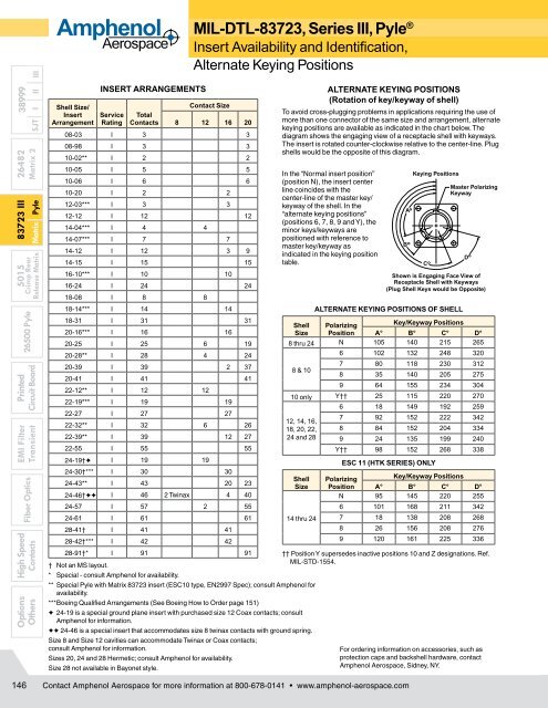
To avoid cross-plugging problems in applications requiring the use of<br />
more than one connector of the same size and arrange ment, alternate<br />
keying positions are available as indicated in the chart below. The<br />
diagram shows the engaging view of a receptacle shell with keyways.<br />
The insert is rotated counter-clockwise relative to the center-line. Plug<br />
shells would be the opposite of this diagram.<br />
In the “Normal insert position”<br />
(position N), the insert center<br />
line coincides with the<br />
center-line of the master key/<br />
keyway of the shell. In the<br />
“alternate keying positions”<br />
(positions 6, 7, 8, 9 and Y), the<br />
minor keys/keyways are<br />
positioned with reference to<br />
mas ter key/keyway as<br />
indicated in the keying position<br />
table.<br />
Shell<br />
Size<br />
ALTERNATE KEYING POSITIONS OF SHELL<br />
Polarizing<br />
Position<br />
Key/Keyway Positions<br />
A° B° C° D°<br />
8 thru 24 N 105 140 215 265<br />
8 & 10<br />
ALTERNATE KEYING POSITIONS<br />
(Rotation of key/keyway of shell)<br />
6 102 132 248 320<br />
7 80 118 230 312<br />
8 35 140 205 275<br />
9 64 155 234 304<br />
10 only Y†† 25 115 220 270<br />
6 18 149 192 259<br />
12, 14, 16,<br />
7 92 152 222 342<br />
18, 20, 22, 8 84 152 204 334<br />
24 and 28 9 24 135 199 240<br />
Y†† 98 152 268 338<br />
Shell<br />
Size<br />
14 thru 24<br />
** Special <strong>Pyle</strong> with Matrix <strong>83723</strong> insert (ESC10 type, EN2997 Spec); consult <strong>Amphenol</strong> for<br />
availability.<br />
*** Boeing Qualified Arrangements (See Boeing How to Order page 151)<br />
F 24-19 is a special ground plane insert with purchased size 12 Coax contacts; consult<br />
<strong>Amphenol</strong> for information.<br />
FF 24-46 is a special insert that accommodates size 8 twinax contacts with ground spring.<br />
Size 8 and Size 12 cavities can accommodate Twinax or Coax contacts;<br />
consult <strong>Amphenol</strong> for information.<br />
Sizes 20, 24 and 28 Hermetic; consult <strong>Amphenol</strong> for availability.<br />
Size 28 not available in Bayonet style.<br />
B<br />
A<br />
°<br />
°<br />
Keying Positions<br />
C<br />
°<br />
Master Polarizing<br />
Keyway<br />
Shown is Engaging Face View of<br />
Receptacle Shell with Keyways<br />
(Plug Shell Keys would be Opposite)<br />
ESC 11 (HTK SERIES) ONLY<br />
Polarizing<br />
Key/Keyway Positions<br />
Position A° B° C° D°<br />
N 95 145 220 255<br />
6 101 168 211 342<br />
7 18 138 208 268<br />
8 26 156 208 276<br />
9 120 161 225 336<br />
†† Position Y supersedes inactive positions 10 and Z designations. Ref.<br />
<strong>MIL</strong>-STD-1554.<br />
For ordering information on accessories, such as<br />
protection caps and backshell hardware, contact<br />
<strong>Amphenol</strong> <strong>Aerospace</strong>, Sidney, NY.<br />
D<br />
°<br />
146<br />
Contact <strong>Amphenol</strong> <strong>Aerospace</strong> for more information at 800-678-0141 • www.amphenol-aerospace.com