MIL-DTL-83723, Series III, Pyle ® - Amphenol Aerospace
MIL-DTL-83723, Series III, Pyle ® - Amphenol Aerospace
MIL-DTL-83723, Series III, Pyle ® - Amphenol Aerospace

You also want an ePaper? Increase the reach of your titles
YUMPU automatically turns print PDFs into web optimized ePapers that Google loves.
Options High Speed<br />
EMI Filter Printed<br />
5015 <strong>83723</strong> <strong>III</strong> 26482 38999<br />
Others<br />
Fiber Optics<br />
Transient Circuit Board<br />
26500 <strong>Pyle</strong> Crimp Rear<br />
Contacts Release Matrix Matrix <strong>Pyle</strong> Matrix 2 SJT I II <strong>III</strong><br />
<strong>Amphenol</strong><br />
<strong>Aerospace</strong><br />
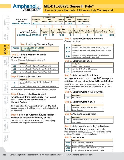
Step 1. Military Connector Type<br />
<strong>MIL</strong>-<strong>DTL</strong>-<strong>83723</strong>, <strong>Series</strong> <strong>III</strong>, <strong>Pyle</strong> ®<br />
How to Order – Hermetic, Military or <strong>Pyle</strong> Commercial<br />
1. 2. 3. 4. 5.<br />
Connector Style<br />
and<br />
Contact Type (Crimp)<br />
Shell Size/<br />
Insert<br />
Arrangement<br />
<strong>MIL</strong>-<strong>DTL</strong>-<strong>83723</strong>, Connector<br />
Service<br />
<strong>Series</strong> <strong>III</strong><br />
Type<br />
Class<br />
<strong>MIL</strong>ITARY HERMETIC M<strong>83723</strong> /88 y 16-24 6<br />
M<strong>83723</strong><br />
Designates <strong>MIL</strong>-<strong>DTL</strong>-<strong>83723</strong><br />
<strong>Series</strong> <strong>III</strong> Connectors<br />
Step 2. Select a Military Hermetic<br />
Connector Style<br />
Alternate Keying<br />
Position of Shell<br />
1. 2. 3. 4. 5. 6. 7. 8.<br />
<strong>Amphenol</strong> ® <strong>Pyle</strong> ® Connector Shell<br />
Shell Size/<br />
Insert Contact Contact Alternate Contact Alternate Keying Varia-<br />
<strong>MIL</strong>-<strong>DTL</strong>-<strong>83723</strong>, <strong>Series</strong> <strong>III</strong> Style Style Arrangement Type Style Finish Position of Shell tions<br />
COMMERCIAL HERMETIC BTY -17 16-24 S 1 D 06 XXXX<br />
(Refer to military specification slash sheet number.)<br />
Designates<br />
/88 Hermetic, Threaded Square Flange Receptacle<br />
/89 Hermetic, Threaded Jam Nut (D-Hole Mount) Receptacle<br />
/90 Hermetic, Threaded Solder Mounted Receptacle<br />
Step 3. Select a Service Class<br />
Y<br />
P<br />
Designates<br />
Hermetic, Stainless Steel, 200°C, with Solderwell<br />
Contacts<br />
Hermetic, Stainless Steel, 200°C, with Eyelet Contacts<br />
For availability of a Plated Steel Shell, consult <strong>Amphenol</strong> <strong>Aerospace</strong>.<br />
Step 4. Select a Shell Size & Insert<br />
Arrangement from chart on pg. 146. (except<br />
sizes 24 and 28 are not available in<br />
Hermetic Styles.)<br />
Shell Size & Insert Arrangements are on page 146. First<br />
number represents Shell Size, second number is the Insert<br />
Arrangement<br />
Step 5. Select an Alternate Keying Position -<br />
Rotation of master key/keyway of shell.<br />
Use N for normal. Use 6, 7, 8, 9 or Y for alternate keying<br />
positions. See page 146 for descriptions.<br />
Step 1. Select a Commercial Hermetic<br />
Connector Style<br />
BTY<br />
BFY<br />
BNY<br />
Designates<br />
Hermetic, Threaded, Stainless Steel, with ‘O’ ring seal<br />
Hermetic, Threaded, Stainless Steel, with Static/Dynamic<br />
Seal<br />
Hermetic, Threaded, Stainless Steel, Electro-deposited<br />
Nickel plated, with Static/Dynamic Seal<br />
Step 2. Select a Shell Style<br />
Designates<br />
-17 Square Flange Receptacle<br />
-19 Jam Nut (D-Hole Mount) Receptacle<br />
-14 Solder Mounted Receptacle<br />
Step 3. Select a Shell Size & Insert<br />
Arrangement from chart on pg. 146. (except sizes<br />
24 and 28 are not available in Hermetic Styles).<br />
Shell Size & Insert Arrangements are on page 146. First<br />
number represents Shell Size, second number is the Insert<br />
Arrangement<br />
Step 4. Select a Contact Type (Crimp)<br />
P<br />
Designates<br />
Pin Contacts<br />
Step 5. Select a Contact Style<br />
Designates<br />
1 Solderwell Contacts (Mil-Spec Type)<br />
4 Eyelet Contacts<br />
Step 6. Alternate Contact Finish<br />
D<br />
V<br />
Designates<br />
.000050 (per <strong>MIL</strong>-<strong>DTL</strong>-<strong>83723</strong>, <strong>III</strong>) Gold<br />
.000100 Gold<br />
Step 7. Select an Alternate Keying Position -<br />
Rotation of master key/keyway of shell.<br />
Omit for normal. Use 06, 07, 08, 09 or Y for alternate keying<br />
positions. See page 146 for descriptions.<br />
Step 8. Variations<br />
Y144<br />
Y163<br />
Y186<br />
Y188<br />
Designates<br />
260°C Capability (Euro Market)<br />
200°C Capability (Euro Market)<br />
260°C Capability per G.E. M50TF3564, Class B<br />
200°C Capability per G.E. M50TF3564, Class A<br />
156<br />
Contact <strong>Amphenol</strong> <strong>Aerospace</strong> for more information at 800-678-0141 • www.amphenol-aerospace.com