RegO® Cylinder & Service Valves - Gas Equipment Company, Inc.
RegO® Cylinder & Service Valves - Gas Equipment Company, Inc.
RegO® Cylinder & Service Valves - Gas Equipment Company, Inc.

Create successful ePaper yourself
Turn your PDF publications into a flip-book with our unique Google optimized e-Paper software.
LP-<strong>Gas</strong> <strong>Cylinder</strong> <strong>Valves</strong> & <strong>Service</strong> <strong>Valves</strong><br />
ECII ® Safety Warnings<br />
Purpose<br />
RegO ® <strong>Cylinder</strong> & <strong>Service</strong> <strong>Valves</strong><br />
In its continuing quest for safety, Engineered Controls International, <strong>Inc</strong>. is publishing safety warning bulletins explaining the hazards<br />
associated with the use, misuse and aging of LP-<strong>Gas</strong> valves and regulators. It is hoped that these factual bulletins will make clear to<br />
LP-<strong>Gas</strong> dealer managers and service personnel that the utmost care and attention must be used in the installation, inspection and<br />
maintenance of these products, or problems could occur which would result in personal injury and property damage.<br />
The National Fire Protection Association Pamphlet #58 “Storage and Handling of Liquefied Petroleum <strong>Gas</strong>es” states in Section 1-6<br />
that “In the interests of safety, all persons employed in handling LP-<strong>Gas</strong>es shall be trained in proper handling and operating procedures.”<br />
ECII ® Warning Bulletins may be useful in training new employees and reminding older employees of potential hazards that<br />
can occur.<br />
It is recommended that all employees be furnished with a copy of NPGA Safety Pamphlet 306-88 “LP-<strong>Gas</strong> Regulator and Valve<br />
Inspection and Maintenance.”<br />
Nature of Warnings<br />
It is recognized that warnings should be as brief as possible, but the<br />
factors involved in cylinder valve failure are many because of the multiple<br />
functions the valve serves. If there is any simple warning, it would<br />
be:<br />
Check cylinder valves for leaking components every time cylinders<br />
are filled.<br />
The bulletin is not intended to be an exhaustive treatment of the subject<br />
of cylinder valves and certainly does not cover all safety practices<br />
that should be followed in installation, operation and maintenance of<br />
LP-<strong>Gas</strong> systems which include cylinder valves.<br />
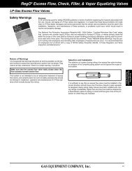
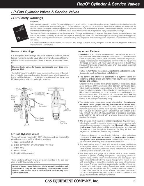
Pressure<br />
Relief<br />
Valve<br />
Bonnet & Stem<br />
Seal Assembly<br />
Outlet<br />
Connection<br />
Fixed Liquid<br />
Level Gauge<br />
Outlet<br />
Connection<br />
Excess<br />
Flow Valve<br />
LP-<strong>Gas</strong> <strong>Cylinder</strong> <strong>Valves</strong><br />
These valves are mounted in DOT cylinders, and are intended to<br />
provide one or more of the following functions:<br />
1. Vapor service shut-off<br />
2. Liquid service shut-off (with excess flow valve)<br />
3. Liquid filling<br />
4. Pressure relief<br />
5. Fixed liquid level gauge<br />
These functions, although simple, are extremely critical in the safe operation<br />
of an LP-<strong>Gas</strong> cylinder system.<br />
Abuse of these valves, failure to follow a good installation and<br />
maintenance program and attempting to use cylinder valves<br />
beyond their normal service life can result in extremely hazardous<br />
conditions.<br />
Important Factors:<br />
1. Installation: It should not be necessary to remind the readers that<br />
cylinder valves must be installed and used in strict conformance with<br />
NFPA Pamphlet 58, and all other applicable codes and regulations.<br />
Codes, regulations and manufacturers’ recommendations have been<br />
developed by experts with many years of experience in the LP-<strong>Gas</strong><br />
industry in the interest of safety for users of LP-<strong>Gas</strong> and all personnel<br />
servicing LP-<strong>Gas</strong> systems.<br />
Failure to fully follow these codes, regulations and recommendations<br />
could result in hazardous installations.<br />
2. The bonnet and stem seal assembly of a cylinder valve are<br />
extremely critical, since any malfunction could cause external<br />
leakage and spillage.<br />
Check bonnet to see that it is in proper position. If there is any doubt<br />
about tightness of threaded connection between bonnet and body,<br />
valve must be repaired in accordance with manufacturers’ repair<br />
instructions before cylinder is filled. Handwheel must be in good condition,<br />
stem threads must not be worn or damaged and bonnet must<br />
be properly assembled. This area should be examined each time the<br />
cylinder if filled. A leakage test should be conducted while the shut-off<br />
valve is in the open position during filling.<br />
3. The cylinder outlet connection is usually a female POL. Threads must<br />
be free of dents, gouges and any indication of excessive wear.<br />
Seating surface inside this connection must be smooth and free of<br />
nicks and scratches to assure a gas tight seal when connected to a<br />
male POL cylinder adapter. <strong>Cylinder</strong> adapter must spin on freely all the<br />
way, without indication of drag, roughness or excessive looseness,<br />
and must then be tightened with a wrench. Connection must be<br />
checked for leakage.<br />
4. The pressure relief valve is of critical importance: Its proper operation<br />
is vital in avoiding excessive pressures during emergencies, such<br />
as overfilling or exposure to excessive heat. No repair of this device<br />
is allowable. Relief valve should be visually inspected and checked<br />
for leaks each time the cylinder is returned for filling. All flow passages<br />
must be clean and free of foreign material.<br />
Entire assembly must be free of dents, distortion or other indications<br />
of damage. If relief valve appears to contaminated or damaged,<br />
the cylinder valve must be replaced. (Caution: Eye protection must<br />
be used when examining relief valves under pressure.)<br />
5. The liquid service shut-off valve, with excess flow valve provided on<br />
some cylinder valves, is also of critical importance. The excess flow<br />
valve must be periodically tested for proper performance, in addition<br />
to the inspection of the shut-off valve.<br />
6. The fixed liquid level gauge on a cylinder valve is, when present,<br />
essential to prevent overfilling the cylinder. The gauging valve must<br />
operate freely, venting vapor when loosened, and sealing gas-tight<br />
easily when tightened with the fingers. Gauge valves meant for use<br />
with a socket key or screwdriver must also seal easily without excessive<br />
torque. The fixed liquid level gauge diptube must be of the proper<br />
length, and be in proper position. Periodic test should be conducted<br />
by weighing the cylinder after filling, to determine that it does not<br />
contain more than the allowable amount of LP-<strong>Gas</strong>. This check<br />
should be done periodically, and any time there is suspicion that the<br />
gauge diptube may be damaged or broken.<br />
25
RegO ® <strong>Cylinder</strong> & <strong>Service</strong> <strong>Valves</strong><br />
Do Not Overfill <strong>Cylinder</strong>s<br />
Do not fill a cylinder without first repairing or replacing the cylinder<br />
valve, as required, if any defect is noted.<br />
While not required by codes, it is recommended that a plug or suitable<br />
protection be inserted in the POL outlet of the cylinder valve at all times<br />
except during filling and while connected for use. This will guard against<br />
discharge of gas should the handwheel be inadvertently opened while<br />
the cylinder is in storage or transit. This is highly advisable for small<br />
cylinders that could be transported inside an automobile or trunk.<br />
It is important that proper wrenches and adapters be used when filling,<br />
servicing and installing cylinder valves in order to avoid damage to the<br />
valve or associated piping.<br />
Customer Safety<br />
Since cylinders are often used by consumers without previous knowledge<br />
of the hazards of LP-<strong>Gas</strong>es and the LP-<strong>Gas</strong> dealers are the only<br />
ones who have direct contact with the consumers, it is the dealers’<br />
responsibility to make sure that his customers are properly<br />
instructed in safety matters relating to their installation.<br />
At the very minimum, it is desirable that these customers:<br />
1. Know the odor of LP-<strong>Gas</strong> and what to do in case they smell gas. Use<br />
of the NPGA “Scratch ’n Sniff” leaflet could be productive.<br />
2. Are instructed never to tamper with the system.<br />
3. Know that when protective hoods are used to enclose regulators<br />
and/or valves, that these hoods must be closed, but not locked.<br />
4. Know the location of the cylinder shut-off valve in emergencies.<br />
General Warning<br />
All ECII ® Products are mechanical devices that will eventually<br />
become inoperative due to wear, contaminants, corrosion and<br />
aging of components made of materials such as metal and rubber.<br />
The environment and conditions of use will determine the safe service life<br />
of these products. Periodic inspection and maintenance are essential.<br />
Because ECII ® Products have a long and proven record of quality and<br />
service, LP-<strong>Gas</strong> dealers may forget the hazards that can occur because<br />
a cylinder valve is used beyond its safe service life. Life of a cylinder<br />
valve is determined by the environment in which it “lives”. The LP-<strong>Gas</strong><br />
dealers know better than anyone what this environment is.<br />
NOTE: There is a developing trend in state legislation and in proposed<br />
national legislation to make the owners of products responsible for<br />
replacing products before they reach the end of their safe useful life. LP-<br />
<strong>Gas</strong> dealers should be aware of legislation which could affect them.<br />
Thread Specifications<br />
<strong>Cylinder</strong> Valve Threads<br />
Because of the many thread forms available on equipment used in the LP-<strong>Gas</strong><br />
industry today, the maze of letters, numbers and symbols which make up various<br />
thread specifications becomes confusing. To help eliminate some of this confusion,<br />
a brief explanation of some of the more widely used thread specifications is<br />
shown below.<br />
Inlet Connections<br />
Hand engagement of all<br />
Overall length of all except NGT<br />
Overall length of NGT<br />
NGT and NPT Threads<br />
The NGT (National <strong>Gas</strong> Taper) thread is the commonly used valve-to-cylinder connection.<br />
The male thread on the valve has about two more threads at the large end<br />
than the NPT in order to provide additional fresh threads if further tightening is necessary.<br />
Additionally, the standard 3 ⁄4" NGT valve inlet provides the greater tightness<br />
at the bottom of the valve by making the valve threads slightly straighter than the<br />
standard taper of 3 ⁄4" per foot in NPT connections. In all other respects NPT and<br />
NGT threads are similar.<br />
Outlet Connections<br />
CGA Outlets<br />
The CGA (Compressed <strong>Gas</strong> Association) outlets are standard for use<br />
with various compressed gases. The relation of one of these outlets to<br />
another is fixed so as to minimize undesirable connections. They have<br />
been so designed to prevent the interchange of connections which may<br />
result in a hazard.<br />
3/8"-18 NPT Thread Connection<br />
This connection also is used for vapor or liquid withdrawal. It has a 3 ⁄8"<br />
diameter thread, and 18 threads per inch, National Pipe Taper Outlet<br />
form.<br />
<strong>Cylinder</strong><br />
Copper Tubing<br />
Nut<br />
Valve<br />
Outlet<br />
CGA 182, or SAE Flare<br />
This connection assures a leak-tight joining of copper tubing to brass<br />
parts without need for brazing or silver soldering. The common size used<br />
on LP-<strong>Gas</strong> valves and fittings is 3 ⁄8" SAE (Society of Automotive<br />
Engineers) flare. Although this connection is referred to as a 3 ⁄8", because<br />
3<br />
⁄8" OD tubing is used, the thread actually measures 5 ⁄8". The specifications<br />
are .625 – 18 UNF – 2A – RH – EXT, which means .625" diameter<br />
thread, 18 threads per inch, Unified Fine Series Class 2 Tolerances, righthand,<br />
external thread.<br />
26
RegO ® <strong>Cylinder</strong> & <strong>Service</strong> <strong>Valves</strong><br />
<strong>Cylinder</strong> Valve Outlet<br />
Nut<br />
Nipple<br />
Nipple<br />
Nut<br />
<strong>Cylinder</strong><br />
Valve<br />
Outlet<br />
CGA 555<br />
CGA 555 is the standard cylinder valve outlet connection for liquid withdrawal<br />
of butane and/or propane. Thread specification is .903" – 14<br />
NGO – LH – EXT, which means .903" diameter thread, 14 threads per<br />
inch, National <strong>Gas</strong> Outlet form, left-hand external thread.<br />
1 5 ⁄16" Female ACME -<br />
Right Hand<br />
Back Check Assembly<br />
M.POL, CGA 510<br />
CGA 510 or POL<br />
Most widely used in this industry, POL is the common name for the standard<br />
CGA 510 connection. Thread specification is .885" – 14 NGO – LH<br />
– INT, meaning .885" diameter thread, 14 threads per inch, National <strong>Gas</strong><br />
Outlet form, left-hand internal thread. ECII ® POL outlet connections for<br />
LP-<strong>Gas</strong>es conform to this standard.<br />
Quick Connect<br />
Back Check Assembly<br />
Type I Outlet<br />
This connection is designed to mate with either a 1 5 ⁄16" Female ACME or<br />
a Male POL (CGA510). It complies with the ANSI Z21.58 Standard for<br />
Outdoor Cooking Appliances and the Can/CGA-1.6 Standard for<br />
Container Connections. A back check assembly in the outlet is designed<br />
to prevent gas flow until a leak free connection is made with an inlet<br />
adapter. These standards apply to barbecue grill cylinders manufactured<br />
after October 1994.<br />
Type II Outlet<br />
This connection is designed to mate with the Quick Connect Male plug<br />
that complies with the ANSI Z21.58 Standard for Outdoor Cooking<br />
Appliances and the Can/CGA-1.6 Standard for Container connections. A<br />
back check assembly in the outlet is designed to prevent gas flow until a<br />
leak free connection is made with an inlet adapter. These standards<br />
apply to barbecue grill cylinders manufactured after October 1994.<br />
<strong>Cylinder</strong> and <strong>Service</strong> <strong>Valves</strong><br />
General Information<br />
The wide acceptance of ECII ® /RegO ® <strong>Cylinder</strong> <strong>Valves</strong> is based on their<br />
reliable performance as well as their reputation for engineering and manufacturing<br />
excellence. Together with thorough testing, these efforts result<br />
in years of trouble-free service.<br />
ECII ® /RegO ® <strong>Cylinder</strong> <strong>Valves</strong> are listed by Underwriters’ Laboratories and<br />
approved by the Bureau of Explosives for pressure relief valve operation,<br />
wherever applicable. See section on relief valves for important information.<br />
Reliability<br />
ECII ® /RegO ® <strong>Cylinder</strong> <strong>Valves</strong> are built with attention to each detail:<br />
Beginning with comprehensive inspection of forgings and machined<br />
parts, and ending with intense quality testing on each individual valve<br />
prior to shipment. Every valve must pass a stringent and comprehensive<br />
underwater leakage test.<br />
Additionally, valves with pressure reliefs are tested for proper pressure<br />
and operation, including reseating to ensure proper opening<br />
and closing at required pressures. Those equipped with excess flow<br />
checks are tested for compliance with published closing specifications,<br />
and tested to ensure minimum leakage after closing.<br />
Heavy-Duty Valve Stem Seals<br />
ECII ® /RegO ® <strong>Cylinder</strong> <strong>Valves</strong> utilize seat discs and stem seals which resist<br />
deterioration and provide the kind of reliable service required for LP-<strong>Gas</strong> utilization.<br />
Diaphragm or O-Ring stem seals are available.<br />
<strong>Valves</strong> with diaphragm stem seals are recognized for their heavy-duty body<br />
design and are suitable for use in cylinders up to 200 lbs. propane capacity.<br />
O-Ring type stem seals are the most widely accepted in the industry. The simple,<br />
economical and long life design features a tapered and confined nylon<br />
seat disc which provides positive, hand-tight closings, and a faster filling cylinder<br />
valve.<br />
Pressure Relief<br />
ECII ® /RegO ® <strong>Valves</strong> have full-capacity “pop action” pressure reliefs with<br />
start to discharge settings at 375 PSIG.<br />
A Valve for Every Need<br />
ECII ® /RegO ® <strong>Cylinder</strong> <strong>Valves</strong> are available for all LP-<strong>Gas</strong> services; a wide<br />
choice for domestic, commercial, industrial, RV, motor fuel, and lift truck<br />
applications. <strong>Valves</strong> are available with a combination of such options as<br />
pressure reliefs, liquid level gauges, and liquid withdrawal tubes.<br />
Also available for special applications are plumbers’ pot valves, tamperresistant<br />
valves for field service, and dual valves for simultaneous liquid<br />
and vapor service.<br />
Instructions for the Proper Use and Applications<br />
of ECII ® /RegO ® <strong>Cylinder</strong> <strong>Valves</strong><br />
1. Containers and pipe line should be cleaned thoroughly before<br />
valves are installed. Large particles of solid foreign matter can cut<br />
the seating surface of any resilient seat disc, causing the valve to<br />
leak. Care must be exercised in inserting valves into lines or containers<br />
to avoid damaging or exerting pressure against pressure<br />
relief valves and outlet connections. Use a minimum amount of a<br />
suitable luting compound on the cylinder valve threads only.<br />
Excess amounts of luting compound can foul the operating parts<br />
of the valves.<br />
2. Do not use excessive force in opening or closing the valves. The<br />
seat disc and diaphragm materials permit the valves to be opened<br />
and closed easily by hand. Never use a wrench on wheel handle<br />
valves.<br />
3. When the design of the piping installation allows liquid to be locked<br />
between two valves, a hydrostatic relief valve must be installed in<br />
the line between the two valves. The pressures which can develop<br />
due to temperature increase in a liquid full line are tremendous and<br />
can cause rupture of the line or damage to the valves.<br />
4. The valves are designed to withstand normal atmospheric temperatures.<br />
They should not, however, be subjected to abnormally high<br />
temperatures.<br />
27
RegO ® <strong>Cylinder</strong> & <strong>Service</strong> <strong>Valves</strong><br />
Design Features of ECII ® and RegO ® <strong>Cylinder</strong> <strong>Valves</strong><br />
Valve Stems On 901, 9101<br />
and 9103 <strong>Valves</strong><br />
Are machined with a double lead<br />
thread for quick opening and closing<br />
as well as high lift.<br />
Forged Brass Body<br />
Back Seat On 901, 9101 and 9103<br />
<strong>Valves</strong><br />
Is metal-to-metal seating to provide<br />
added protection against leakage while<br />
the valve is open. Back seat the valve<br />
while in operation.<br />
O-Rings<br />
For positive leak-proof seals under<br />
temperature and pressure variations.<br />
Pressure Relief<br />
Provides quick discharge of excess<br />
pressure. Relief seat disc is special<br />
resilient composition rubber.<br />
Tapered Seat Openings<br />
On 9101 and 9103 <strong>Valves</strong><br />
Permit increased flow rates<br />
resulting in faster charging.<br />
Seat Disc<br />
Is a tapered nylon in a fully confined seat<br />
to ensure easy, leak-free, positive shutoffs.<br />
Seat disc also provides a separate<br />
swivel action to minimize scoring by<br />
impurities.<br />
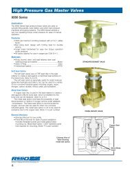
Compact <strong>Cylinder</strong> <strong>Valves</strong> with<br />
Overfilling Prevention Devices<br />
The 907NFD Series <strong>Cylinder</strong> <strong>Valves</strong> are designed for use<br />
on DOT LP-<strong>Gas</strong> <strong>Cylinder</strong>s up to 40 lbs. The outlet features<br />
a back check assembly – designed to prevent gas<br />
flow until a leak free connection is made with an inlet<br />
adapter.<br />
These valves comply with both the ANSI Z21.58<br />
Standard for Outdoor Cooking Appliances and the<br />
CAN/CGA-1.6 Standard for Container Connections<br />
which apply to new barbecue grill cylinders manufactured<br />
after October 1994. They also conform to requirements<br />
in the 1998 edition of NFPA 58.<br />
907NFD Series<br />
Type I <strong>Valves</strong><br />
Ordering Information<br />
Part<br />
Number<br />
Dip Tube<br />
Length with<br />
Deflector<br />
For use on<br />
DOT <strong>Cylinder</strong>s<br />
Up To:<br />
Container<br />
Connection<br />
<strong>Service</strong> Connection<br />
Type<br />
Description<br />
Fixed Liquid<br />
Level Vent<br />
Valve Style<br />
Pressure<br />
Relief<br />
Valve Setting<br />
Accessories<br />
ACME Dust<br />
Cap<br />
907NFD3.0 3.0" 5 lbs.<br />
907NFD4.0 4.0" 20 lbs.<br />
907NFD4.8 4.8" 30 lbs.<br />
907NFD6.5 6.5" 40 lbs.<br />
3<br />
⁄4" M. NGT Type I<br />
1 5 ⁄16" M. ACME<br />
and F. POL<br />
CGA 791<br />
Slotted<br />
375 PSIG<br />
907-12<br />
<strong>Inc</strong>luded<br />
Always check Diptube length to assure accuracy of fixed liquid level. <strong>Cylinder</strong>s should be filled by weight. Check all authorities having jurisdiction.<br />
28
RegO ® <strong>Cylinder</strong> & <strong>Service</strong> <strong>Valves</strong><br />
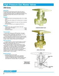
Heavy-Duty <strong>Cylinder</strong> <strong>Valves</strong> for Vapor Withdrawal<br />
This heavy duty cylinder valve is designed for vapor withdrawal of DOT cylinders up to 100<br />
lbs. propane capacity. It is used in domestic hook-ups, with RV's and as a heavy duty barbecue<br />
cylinder valve.<br />
9103D<br />
Part<br />
Number<br />
Container<br />
Connection<br />
<strong>Service</strong><br />
Connection<br />
Fixed<br />
Liquid<br />
Level<br />
Vent Valve<br />
Style<br />
Dip<br />
Tube<br />
Length<br />
w/Deflector<br />
9103D04.2<br />
3<br />
⁄4" F. POL<br />
4.2"<br />
9103D10.6 M. NGT (CGA 510) Knurled 10.6"<br />
9103D11.6 11.6"<br />
Pressure<br />
Relief<br />
Valve<br />
Setting<br />
375<br />
PSIG<br />
For Use In<br />
<strong>Cylinder</strong>s<br />
w/Propane<br />
Capacity<br />
Up To:<br />
10<br />
PSIG<br />
Approximate Filling Rate<br />
Liquid Flow, GPM<br />
Pressure Drop Across <strong>Valves</strong><br />
25<br />
PSIG<br />
50<br />
PSIG<br />
100<br />
PSIG<br />
Accessories<br />
POL<br />
Plug<br />
100 lbs. 12.7 20.3 29.0 41.3 970EZP<br />
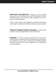
<strong>Cylinder</strong> Valve for RV and Small ASME System Vapor Withdrawal<br />
Designed especially for vapor withdrawal service in small ASME containers with surface<br />
area up to 23.8 square feet. UL flow capacity is 645 CFM/air, per NFPA 58.<br />
Part<br />
Number<br />
9106CO<br />
Container<br />
Connection<br />
3<br />
⁄4"<br />
M. NGT<br />
<strong>Service</strong><br />
Connection<br />
F. POL<br />
(CGA 510)<br />
Fixed<br />
Liquid<br />
Level<br />
Vent Valve<br />
Style<br />
None<br />
Pressure<br />
Relief<br />
Valve<br />
Setting<br />
312<br />
PSIG<br />
For Use In<br />
<strong>Cylinder</strong>s<br />
w/Propane<br />
Capacity<br />
Up To:<br />
ASME<br />
Tanks*<br />
Flow<br />
Capacity<br />
SCFM/Air<br />
645<br />
* Surface area up to 23.8 square feet.<br />
<strong>Cylinder</strong> Valve for Liquid Withdrawal<br />
Equipped with excess flow valves and liquid withdrawal tubes, they are designed for liquid withdrawal of DOT cylinders<br />
up to 100 lbs. propane capacity. They are most often used with heavy BTU loads found in industrial uses.<br />
Part<br />
Number<br />
Container<br />
Connection<br />
<strong>Service</strong><br />
Connection<br />
Fixed<br />
Liquid<br />
Level<br />
Vent Valve<br />
Style<br />
Dip Tube<br />
Length<br />
w/Deflector<br />
Liquid<br />
Withdrawal<br />
Tube<br />
Length<br />
9107K8A<br />
3<br />
⁄4"<br />
M. NGT<br />
CGA 555 Knurled 11.6" 44"<br />
Pressure<br />
Relief<br />
Valve<br />
Setting<br />
For Use In<br />
<strong>Cylinder</strong>s<br />
w/Propane<br />
Capacity<br />
Up To:<br />
10<br />
PSIG<br />
Approximate Filling Rate<br />
Liquid Flow, GPM<br />
Pressure Drop Across Valve 25<br />
25 50 100<br />
PSIG PSIG PSIG<br />
PSIG<br />
Inlet<br />
Closing Flow (LP-<strong>Gas</strong>)*<br />
Vapor<br />
100<br />
PSIG<br />
Inlet<br />
Liquid<br />
375<br />
PSIG<br />
100<br />
lbs.<br />
3.3 5.4 7.7 11.1<br />
525<br />
SCFH<br />
1,000<br />
SCFH<br />
1.7<br />
GPM<br />
*Closing flows based on 3 ⁄8" O.D. withdrawal tube 44" long or less attached.<br />
IMPORTANT: 1 ⁄4" O.D. pigtails or POL connections for 1 ⁄4" O.D. pigtails should not be used with these valves.<br />
NOTES: To ensure proper functioning and maximum protection from excess flow valves, the cylinder valve should be fully opened and backseated<br />
when in use. These valves incorporate an excess flow valve. Refer to L-500 / Section F, for complete information regarding selection, operation and<br />
testing of excess flow valves.<br />
29
RegO ® <strong>Cylinder</strong> & <strong>Service</strong> <strong>Valves</strong><br />
“Dual” <strong>Cylinder</strong> Valve for Simultaneous Liquid and Vapor Withdrawal<br />
This dual cylinder valve was designed especially for industrial uses. It<br />
increases the cylinder’s flexibility by permitting DOT cylinders up to 100<br />
lbs. propane capacity to be used interchangeably or simultaneously for<br />
either liquid or vapor withdrawal.<br />
Part<br />
Number<br />
Container<br />
Connection<br />
Vapor<br />
<strong>Service</strong><br />
Connection<br />
Liquid<br />
Fixed<br />
Liquid<br />
Level<br />
Vent Valve<br />
Style<br />
Liquid<br />
Withdrawal<br />
Tube<br />
Length<br />
8556 3<br />
⁄4" M. NGT<br />
F. POL<br />
(CGA 510)<br />
CGA<br />
555<br />
None 44"<br />
Pressure<br />
Relief<br />
Valve<br />
Setting<br />
For Use In<br />
<strong>Cylinder</strong>s<br />
w/Propane<br />
Capacity<br />
Up To:<br />
10<br />
PSIG<br />
Approximate Filling Rate<br />
Liquid Flow, GPM<br />
Pressure Drop Across Valve<br />
25 50<br />
PSIG PSIG<br />
100<br />
PSIG<br />
Liquid<br />
Closing<br />
Flow*<br />
(LP-<strong>Gas</strong>)<br />
375<br />
PSIG<br />
100<br />
lbs.<br />
6.6 10.0 14.5 21.0<br />
2.3<br />
GPM<br />
*To ensure proper functioning and maximum protection from integral excess flow valves, the cylinder valve<br />
should be fully opened and backseated when in use.<br />
NOTE: These valves incorporate an excess flow valve. Refer to L-500/Section F, for complete information<br />
regarding selection, operation and testing of excess flow valves.<br />
Saf-T-Lock For POL <strong>Service</strong> <strong>Valves</strong><br />
Securely locks POL service valves to help prevent unauthorized hookups,<br />
reduces pilferage and increases security.<br />
Part<br />
#<br />
Description<br />
510<br />
Saf-T-Lock<br />
510-K<br />
Saf-T-Lock Key<br />
30
RegO ® <strong>Cylinder</strong> & <strong>Service</strong> <strong>Valves</strong><br />
<strong>Service</strong> <strong>Valves</strong> for ASME and DOT Containers or Fuel Line Applications<br />
Designed especially for vapor withdrawal service on ASME and DOT<br />
containers or in fuel line applications. Since none of these valves have an<br />
integral pressure relief valve, they may only be used as an accessory<br />
valve on containers that have an independent pressure relief valve sufficient<br />
for that container’s capacity.<br />
901C1<br />
9101R1<br />
9101D<br />
Part<br />
Number<br />
Bonnet<br />
Style<br />
Container<br />
Connection<br />
<strong>Service</strong><br />
Connection<br />
Fixed<br />
Liquid<br />
Level<br />
Vent Valve<br />
Approximate Filling Rate<br />
Liquid Flow, GPM<br />
Pressure Drop Across Valve<br />
901C1<br />
5.3 8.2 10.8 14.2<br />
No<br />
9101C1 8.8 12.4 15.8 21.7<br />
Standard<br />
9101D11.1<br />
3<br />
F. POL<br />
Yes<br />
8.6 12.7 16.3 22.3<br />
9101D11.7<br />
⁄4" M. NGT<br />
CGA 510<br />
9101R1<br />
No<br />
9101R11.1<br />
9101R11.7<br />
MultiBonnet<br />
NOTE: Since these valves have no integral pressure relief valve, they can be used on any container with an independent relief device sufficient for that tank’s capacity.<br />
<strong>Service</strong> <strong>Valves</strong> for ASME Motor Fuel Containers<br />
Yes<br />
10<br />
PSIG<br />
7.6<br />
25<br />
PSIG<br />
50<br />
PSIG<br />
100<br />
PSIG<br />
11.7 15.2 20.6<br />
Designed specifically for vapor or liquid withdrawal service on ASME<br />
motor fuel containers. Since none of these valves have an integral pressure<br />
relief valve, they may only be used as an accessory valve on containers<br />
that have an independent pressure relief valve sufficient for that<br />
container’s capacity.<br />
The integral excess flow valve found in all these service valves helps prevent<br />
excessive product loss in the event of fuel line rupture.<br />
When installed for liquid withdrawal, the 9101H6 has provisions for<br />
attachment of a liquid withdrawal tube. All other valves must be installed<br />
in containers that have provisions for a separate liquid withdrawal.<br />
To insure proper functioning and maximum protection from integral<br />
excess flow valves, these service valves should be fully opened and<br />
backseated when in use.<br />
901C5<br />
9101H5<br />
9101H6<br />
Part<br />
Number<br />
901C3<br />
901C5<br />
Container<br />
Connection<br />
<strong>Service</strong><br />
Connection<br />
Liquid<br />
Withdrawal<br />
Connection<br />
25 PSIG<br />
Inlet (SCFH)<br />
Closing Flow (LP-<strong>Gas</strong>)<br />
Vapor<br />
100 PSIG<br />
Inlet (SCFH)<br />
Liquid<br />
GPM<br />
F. POL<br />
350 *** 605 ***<br />
2.6 ***<br />
CGA 510 None<br />
550 *** 1050 ***<br />
9101H5* 3<br />
⁄4" M. NGT 3 ⁄8" SAE Flare<br />
765 ** 1300 ** 3.6 **<br />
9101H6* 1<br />
⁄4" NPT 550 **** 1050 **** 2.6 ****<br />
9101Y5H*<br />
60° Angle<br />
3<br />
⁄8" SAE Flare<br />
None 550 ** 1050 ** 3.6 **<br />
* Heavy-duty models<br />
** Based on 3 ⁄8" O.D. pigtail, 20" long or less, connected to valve outlet. For greater lengths, the pigtail must have a larger O.D.<br />
*** Same as (**). In addition, 1 ⁄4" O.D. pigtails or POL connections for 1 ⁄4" O.D. should not be used with this valve.<br />
**** Based on 3 ⁄8" O.D. pigtail; 20: long or less, connected to valve outlet. Also based on 1 ⁄4" pipe size dip tube, 42" long or less, attached to special inlet<br />
connection. For longer pigtail lengths, the diameter of the pigtail must be increased.<br />
NOTE: These valves incorporate an excess flow valve. Refer to L-500/Section F, for complete information regarding selection, operation and testing of<br />
excess flow valves.<br />
9101Y5H<br />
31
RegO ® <strong>Cylinder</strong> & <strong>Service</strong> <strong>Valves</strong><br />
<strong>Service</strong> <strong>Valves</strong> for DOT Fork Lift Containers<br />
Designed specifically for vapor or liquid withdrawal service on DOT fork<br />
lift containers. <strong>Valves</strong> with 1.5 GPM closing flow are for use in small and<br />
medium size lift truck applications, while those with 2.6 GPM closing<br />
flow are for large lift trucks and gantry crane type vehicles. Since none of<br />
these valves have an integral pressure relief valve, they may only be used<br />
as an accessory valve on containers that have an independent pressure<br />
relief valve sufficient for that cylinders capacity.<br />
The integral excess flow valve found in all these service valves helps prevent<br />
excessive product loss in the event of fuel line rupture.<br />
When installed for liquid withdrawal, the 9101P6 Series has provisions<br />
for attachment of a liquid withdrawal tube. The 9101P5 Series<br />
must be installed in containers that have provisions for a separate<br />
liquid withdrawal.<br />
To insure proper functioning and maximum protection from integral<br />
excess flow valves, these service valves should be fully opened and<br />
backseated when in use.<br />
9101P5<br />
9101P5H<br />
9101P6<br />
9101P6H<br />
Part<br />
Number<br />
Container<br />
Connection<br />
<strong>Service</strong><br />
Connection<br />
Liquid<br />
Withdrawal<br />
Connection<br />
Adhesive Warning Labels<br />
25 PSIG<br />
Inlet (SCFH)<br />
Closing Flow (LP-<strong>Gas</strong>)<br />
Vapor<br />
100 PSIG<br />
Inlet (SCFH)<br />
Liquid<br />
(GPM)<br />
9101P5<br />
430 900 1.5<br />
None<br />
9101P5H 550 1050 2.6<br />
3<br />
⁄4" M. NGT 3<br />
⁄8" M. NPT<br />
9101P6<br />
430 900 1.5<br />
1<br />
⁄4" NPT<br />
9101P6H 550 1050 2.6<br />
NOTE: These valves incorporate an excess flow valve. Refer to L-500/Section F, for complete information regarding selection, operation and testing of excess flow valves.<br />
10<br />
PSIG<br />
Approximate Filling Rate<br />
Liquid Flow, GPM<br />
Pressure Drop Across Valve<br />
25<br />
PSIG<br />
50<br />
PSIG<br />
5.0 7.6 10.7 14.9<br />
4.5 7.2 10.3 14.8<br />
Accessories<br />
ACME Check Connectors<br />
100<br />
PSIG Male Female Cap<br />
7141M<br />
7141F<br />
7141M-40<br />
or<br />
7141FP<br />
These adhesive warning labels are intended for application<br />
as close as possible to the cylinder valve<br />
and/or service valve.<br />
Part<br />
Number<br />
901-400<br />
903-400<br />
Description<br />
Adhesive Label Primarily for Fork Lift<br />
<strong>Cylinder</strong>s<br />
Adhesive Label Primarily for Small DOT<br />
<strong>Cylinder</strong>s<br />
DANGER<br />
LP GAS IS EXTREMELY FLAMMABLE AND EXPLOSIVE<br />
AVOID SERIOUS INJURY AND PROPERTY DAMAGE. IF YOU SEE, SMELL, OR HEAR ESCAPING GAS...EVACUATE AREA<br />
IMMEDIATELY! CALL YOUR LOCAL FIRE DEPARTMENT! DO NOT ATTEMPT TO REPAIR. DO NOT STORE IN BUILDING OR<br />
ENCLOSED AREA. DO NOT USE ON HOT AIR BALLOONS OR AIRCRAFT.<br />
This container is filled with highly flammable LP-<strong>Gas</strong> under pressure. A<br />
serious fire or explosion can result from leaks and misuse or mishandling of<br />
the container and its valves. Do not move, hold or lift the container by any<br />
of its valves. Do not expose to fire or temperature above 120°F (49°C). Do<br />
not overfill.<br />
This container incorporates a pressure relief valve. The pressure relief valve<br />
can expel a large jet of LP-<strong>Gas</strong> into the air if the container is (1) exposed to<br />
high temperatures—over 120°F (49°C) or (2) overfilled and exposed to a<br />
temperature higher than the temperatures at the time it was filled.<br />
The pressure relief valve is equipped with a protective cover. The protective<br />
cover must remain in place at all times except when inspecting the<br />
valve. CAUTION...use eye protection. If dust, dirt, moisture or other foreign<br />
material collect in the valve, it may not function properly to prevent container<br />
rupture or minimize product loss after opening.<br />
Each time the container is filled, the pressure relief valve must be checked<br />
to ensure that it is completely unobstructed and that it has no physical<br />
damage. If there is any doubt about the condition of the valve, the container<br />
must be removed from service and the pressure relief valve must be<br />
replaced.<br />
Only trained personnel should be permitted to fill this container. Before the<br />
container is filled for the first time, it must be purged of air. The total liquid<br />
volume of LP-<strong>Gas</strong> must never exceed the amount designated by<br />
applicable filling density regulations for this container.<br />
Make sure the protective cap is in place on the ACME threaded filler valve<br />
at all times. Never insert a screwdriver or other tools into the valve as it can<br />
damage the seal or guide and cause an uncontrolled leak.<br />
WARNING<br />
Do not allow any overfill. If the fixed liquid level gauge is used during filling, filling<br />
should stop the moment a white LP-<strong>Gas</strong> cloud is emitted from its bleed hole.<br />
Keep the vent closed tightly at all other times. Each time the container is filled,<br />
it must be checked for leaks (with a high quality leak detection solution...leaks<br />
cause bubbles to grow).<br />
Do not disconnect or connect this container without first reading the instructions<br />
accompanying the vehicle or appliance with which this container is intended to<br />
be used. CAUTION...no smoking while connecting or disconnecting this<br />
container.<br />
Make sure the service valve is shut off tightly before beginning to assemble or<br />
disassemble the coupling. Liquid LP-<strong>Gas</strong> may flow or leak from the coupling.<br />
This liquid can cause skin burns, frost bite and other serious injury in addition to<br />
those caused by fire and explosion. CAUTION...Wear proper skin and eye<br />
protection. Any gasket or O-ring in the coupling must be routinely checked for<br />
wear and replaced as required.<br />
After connecting the coupling, make sure the connection is leak tight. Check for<br />
leaks with a high quality leak detection solution (leaks cause bubbles to grow).<br />
If the connection leaks after tightening, close the service valve, disconnect the<br />
coupling and remove from service.<br />
When not in use, keep the service shut-off valve closed.<br />
When in use, keep the service valve fully open.<br />
Keep this equipment out of the reach of children.<br />
This container must be used only in compliance with all applicable laws and<br />
regulations, including National Fire Protection Association Publication No. 58,<br />
which is the law in many states. A copy of this Publication may be obtained by<br />
writing NFPA, Batterymarch Park, Quincy, MA 02269.<br />
DO NOT REMOVE, DEFACE OR OBLITERATE THIS LABEL—DO NOT FILL THIS CONTAINER UNLESS THIS LABEL IS READABLE.<br />
ADDITIONAL SAFETY INFORMATION<br />
IS AVAILABLE FROM:<br />
Engineered Controls<br />
® International, <strong>Inc</strong>.<br />
Printed in U.S.A. 04-0994-1189 Part No. 901-400<br />
100 RegO Drive PO Box 247 Elon College, NC 27244 USA Phone (336) 449-7707 Fax (336) 449-6594 www.regoproducts.c om<br />
DANGER!<br />
WARNING!<br />
LP-GAS IS EXTREMELY FLAMMABLE AND EXPLOSIVE<br />
KEEP CYLINDER OUT OF THE REACH OF CHILDREN<br />
AVOID SERIOUS INJURY AND PROPERTY DAMAGE. IF YOU SEE, SMELL, OR HEAR THE HISS OF ESCAPING GAS...IMMEDIATELY GET AWAY FROM THIS CYLINDER! CALL YOUR<br />
LOCAL FIRE DEPARTMENT! DO NOT ATTEMPT TO REPAIR. DO NOT USE OR STORE IN BUILDING OR ENCLOSED AREA. FOR OUTDOOR USE ONLY.<br />
This cylinder contains highly flammable LP-<strong>Gas</strong> under pressure. A serious CAUTION...eye protection must be worn when examining relief valve. This WHEN MAKING CONNECTIONS TO AN APPLIANCE—<br />
fire or explosion can result from leaks and misuse or mishandling of the valve cannot be repaired. If it is obstructed, the entire cylinder valve must be 1. Do not use this cylinder without first reading the instructions accompanying<br />
the appliance with which this cylinder is intended to be used.<br />
cylinder and its valve. Do not carry, hold or lift the cylinder by its valve. replaced. The Shut-Off Valve may require periodic repair or replacement.<br />
Do not expose to fire or temperatures above 120°F (49°C).<br />
Before the cylinder is filled for the first time, it must be purged of air. 2. Before connecting the <strong>Cylinder</strong> Valve outlet connection to an appliance,<br />
make sure the connection does not contain dirt or debris. These<br />
The cylinder valve incorporates a Shut-Off Valve and Pressure Relief Valve. Total liquid volume must never exceed the amount designated by DOT<br />
The Pressure-Relief Valve can expel a large jet of LP-<strong>Gas</strong> into the air if the for this cylinder.<br />
may cause the connection to leak or may impair the functioning of the<br />
cylinder is (1) exposed to high temperatures —over 120°F (49° C.), or (2) If the cylinder has a fixed liquid level gauge, filling should stop the regulator, creating a hazardous condition.<br />
overfilled and exposed to a temperature higher than the temperature at the moment a white LP-<strong>Gas</strong> cloud is emitted from its bleed hole. Keep the 3. When connecting the <strong>Cylinder</strong> Valve outlet to an appliance<br />
time it was filled.<br />
vent valve closed tightly at all other times.<br />
(CAUTION...counterclockwise thread), make sure the connection is<br />
Never attempt to fill this cylinder yourself. Do not tamper with it or Keep this cylinder firmly secured in an upright position at all times. Do tight. Check for leaks with a high quality leak detection solution (leaks<br />
attempt repairs.<br />
not lay it on its side during transport, storage or use. In other than an upright cause bubbles to grow). If the connection leaks after tightening, close<br />
Only trained LP-<strong>Gas</strong> Dealer personnel should be permitted to fill this position, liquid LP-<strong>Gas</strong> may flow or leak. This liquid can cause skin burns, cylinder valve, disconnect it from the appliance, insert the P.O.L. plug<br />
cylinder and to repair or replace its valve. Each time the cylinder is frostbite and other serious injuries in addition to those caused by fire or and immediately return the cylinder, with the <strong>Cylinder</strong> Valve attached,<br />
filled, the entire cylinder valve must be checked for leaks (with a leak explosion.<br />
to your LP-<strong>Gas</strong> Dealer for examination.<br />
detection solution...leaks cause bubbles to grow). The shut-off valve When not in use: Close the Shut-Off Valve. Insert a protective plug (P.O.L. This cylinder must be used only in compliance with all applicable laws and<br />
and fixed liquid level gauge (if incorporated) must be checked for plug) into the cylinder valve outlet. (CAUTION...counterclockwise thread). regulations, including National Fire Protection Association Publication No.<br />
proper operation. The Pressure-Relief Valve must be checked to ensure The P.O.L. plug must be inserted whenever the cylinder is stored, manually 58, which is the law in many states. A copy of this Publication may be<br />
that it is completely unobstructed and that it has no physical damage. moved, or transported by vehicle.<br />
obtained by writing NFPA, Batterymarch Park, Quincy, MA 02269.<br />
DO NOT REMOVE, DEFACE OR OBLITERATE THIS LABEL—DO NOT FILL THIS CYLINDER UNLESS THIS LABEL IS READABLE.<br />
ADDITIONAL SAFETY INFORMATION<br />
100 RegO Drive PO Box 247 Elon College, NC 27244 USA<br />
IS AVAILABLE FROM:<br />
Phone (336) 449-7707 Fax (336) 449-6594 www.regoproducts.com<br />
Printed in U.S.A. 05-0994-1086<br />
Warning No. 903-400<br />
32
RegO ® MultiValve Assemblies<br />
RegO Multivalve ® Assemblies<br />
General Information<br />
RegO Multivalves ® were pioneered in the 1930’s. By combining several<br />
valve functions in one unit, Multivalves ® made possible new and more<br />
practical tank designs (fewer openings and smaller, less cumbersome<br />
protective hoods). They received immediate acceptance.<br />
The Multivalve ® design has kept pace with changing industry needs over<br />
the years. They are as popular as ever; still keeping fabricating costs<br />
down and reducing operating expenses for the LP-<strong>Gas</strong> dealer.<br />
RegO Multivalves ® Reduce the Cost of Fabrication by<br />
• Combining several valve functions in one less expensive body.<br />
• Reducing the number of threaded openings in ASME containers.<br />
• Diminishing the size and cost of protective hoods.<br />
• Providing generous sized wrenching bosses for quick, easy<br />
installation.<br />
RegO Multivalves ® Reduce LPG Dealer Expenses by<br />
• Permitting on-site filling of 100 lb. to 420 lb. DOT cylinders, thus<br />
eliminating cylinder return and interrupted customer service.<br />
• Providing well-placed hose connections for easy filling.<br />
• Allowing ample space for secure attachment and easy removal of<br />
the regulator.<br />
• Providing substantial savings of bonnet repairs on valves with the<br />
MultiBonnet. ®<br />
RegO Multivalves ® Satisfy Customer Demands for Tough, Safe<br />
<strong>Equipment</strong> with These Features<br />
Heavy-Duty Valve Stem Seals —<br />
• Tapered nylon disc in a fully confined seat resist deterioration and provide<br />
hand-tight closings over a long service life.<br />
Comprehensive Testing —<br />
• Every Multivalve ® must pass a stringent underwater leakage test prior<br />
to shipment.<br />
• Multivalves ® with pressure relief valves are individually tested and<br />
adjusted to assure proper pressure settings.<br />
• Those equipped with excess flow checks are tested for compliance<br />
with published closing specifications and for leakage after closing.<br />
Pressure Relief <strong>Valves</strong> and Other Devices —<br />
• Multivalves ® equipped with integral pressure relief devices employ<br />
full-capacity, “pop-action” reliefs with set pressures of 250 psig for<br />
ASME use and 375 psig for DOT cylinders.<br />
Double Back-Check Filler <strong>Valves</strong> —<br />
• Multivalves ® with filling connections have double backcheck safety. If<br />
the upper check ceases to function, the lower stand-by check will<br />
continue to protect the filling connection from excessive leakage.<br />
Ease of Maintenance —<br />
• Standardization of parts makes it possible for one repair kit to maintain<br />
the bonnet assemblies of RegO ® cylinder valves, service valves,<br />
motor fuel valves, and Multivalves ® .<br />
RegO Multivalves ® fit every LP-<strong>Gas</strong> need.<br />
• Wide selection of Multivalves ® for domestic, commercial, and industrial<br />
needs are available.<br />
• Multivalves ® may be ordered with pressure relief, liquid level tube,<br />
filler valve, vapor equalizing valve, internal pipe connections, liquid<br />
filling and withdrawal connections, and 1 ⁄4" NPT tapped opening for<br />
pressure gauge with or without steel plug.<br />
Design Features of RegO Multivalves ®<br />
Seal Cap<br />
Molded from tough, resilient<br />
plastic to protect threads<br />
and internal working parts.<br />
Designed to protect the filler<br />
opening against dirt and other<br />
foreign materials. Also acts<br />
as a secondary pressure seal.<br />
Long Wearing <strong>Gas</strong>ket<br />
Permits leak-free, hand-tight<br />
connection of the hose<br />
coupling to the filler valve.<br />
Forged Brass Body<br />
MultiBonnet ®<br />
Designed to allow quick and<br />
easy repair of bonnet packings<br />
on Multivalves ® on<br />
active propane systems.<br />
UL Shear Point<br />
Provides for a shear just<br />
below the ACME threads to<br />
protect the container in case<br />
of a pullaway while the hose<br />
is connected. The ACME<br />
connection should shear off<br />
on an angle pull, leaving the<br />
body and check assembly of<br />
the valve still in place.<br />
Filler Seat Disc<br />
Fabricated of special<br />
synthetic composition and<br />
made extra thick for<br />
longer life.<br />
Valve Guide<br />
A precision machined “stem”<br />
to assure positive alignment<br />
“Pop Action” Pressure Relief<br />
Provides quick release of<br />
excess pressure. Relief seat<br />
disc is special resilient<br />
composition rubber designed<br />
to resist bonding to the<br />
valve seat even after years<br />
of service.<br />
33
RegO ® MultiValve Assemblies<br />
RegO MultiBonnet ® Assemblies<br />
Design Features of the MultiBonnet ®<br />
Handwheel<br />
Aluminum die cast handwheel.<br />
Non-Rising Stem<br />
Designed to allow easy backseating and long<br />
service life.<br />
Upper Packing Assembly<br />
Contains both internal and external o-rings.<br />
Provides leak resistant performance.<br />
Internal O-ring<br />
Lower Bonnet and Stem Assembly<br />
Machined brass construction offers durability to<br />
bonnet design.<br />
External O-ring<br />
Nameplate<br />
Provides easy identification of the RegO<br />
MultiBonnet ®.<br />
Teflon Backseat<br />
Provides for upper packing isolation when valve<br />
is fully open.<br />
Machined Double Lead Threads<br />
Provides for quick opening and closing of the<br />
valve.<br />
Shut-off Seat Disc<br />
Tapered nylon disc is retained in a fully confined<br />
seat that helps ensure positive shut-offs.<br />
Application<br />
The MultiBonnet ® is designed to allow quick and easy repair of bonnet<br />
packings in certain Multivalves ® and service valves on active propane<br />
systems. It allows you to repair valve bonnet stem o-ring leaks in minutes,<br />
without interrupting gas service to your customers.<br />
• Eliminates the need to evacuate tanks or cylinders to repair the<br />
MultiBonnet ® packing.<br />
• Two section design allows repair of MultiBonnet ® assemblies on<br />
active propane systems without interruption in gas service or shutting<br />
off appliances downstream. This helps to prevent time consuming<br />
relighting of pilots, special appointments, and call backs.<br />
• Cost of replacing the MultiBonnet ® packing is only 1/3 as much as<br />
replacing a complete bonnet assembly—not including time cost savings,<br />
which can be substantial.<br />
• Available on certain new Multivalves ® and service valves as well as<br />
repair assemblies for many existing RegO ® valves.<br />
• UL listed as a component of valve assembly.<br />
Here’s How The MultiBonnet ® Works<br />
• When the valve is fully open, only the lower stem will rise and backseat<br />
against the teflon washer which isolates the upper packing.<br />
• This allows you to remove the upper packing nut, which contains the<br />
o-rings, and replace it while the valve is fully open and gas service not<br />
interrupted.<br />
34
RegO ® MultiValve Assemblies<br />
ASME Multivalves ® for Vapor Withdrawal<br />
These Multivalves ® are designed for use in single opening ASME containers<br />
equipped with a 2 1 ⁄2" M. NPT riser. They can be used with underground<br />
ASME containers up to 639 sq. ft. surface area, and above<br />
ground ASME containers up to 192 sq. ft. surface area. A separate<br />
opening is required for liquid withdrawal. The MultiBonnet ® is standard on<br />
this valve. The MultiBonnet ® allows quick and easy repair of bonnet.<br />
Part<br />
Number<br />
G8475RV<br />
G8475RW<br />
10<br />
PSIG<br />
Approximate Filling Rate<br />
Liquid Flow, GPM<br />
Pressure Drop Across Valve<br />
25<br />
PSIG<br />
50<br />
PSIG<br />
100<br />
PSIG<br />
42 72 98 125<br />
8475-50<br />
(8475-80 w/out body)<br />
RV-MV3131G<br />
RW-MV3132G<br />
8475-51A<br />
(8475-81A w/out body)<br />
19104-80<br />
Part<br />
Number<br />
G8475RV<br />
G8475RW<br />
Container<br />
Connection<br />
2 1 ⁄2"<br />
F. NPT<br />
<strong>Service</strong><br />
Connection<br />
F. POL<br />
(CGA 510)<br />
Filling<br />
Connection<br />
1 3 ⁄4"<br />
M. ACME<br />
Vapor Equalizing<br />
Connection<br />
Connection<br />
Size<br />
1 1 ⁄4"<br />
M. ACME<br />
UL Listed<br />
Closing<br />
Flow<br />
4200 CFH<br />
@ 100 PSIG<br />
Float<br />
Gauge<br />
Flange<br />
Opening<br />
Fits<br />
“JUNIOR”<br />
Size<br />
Fixed<br />
Liquid<br />
Level<br />
Vent Valve<br />
Style<br />
Dip<br />
Tube<br />
Length<br />
Knurled 30"*<br />
Pressure<br />
Relief<br />
Valve<br />
Setting<br />
250<br />
PSIG<br />
UL Listed<br />
Relief Valve<br />
Capacity<br />
2020<br />
SCFM/air<br />
3995<br />
SCFM/air<br />
For Use In<br />
Containers<br />
w/Surface<br />
Area Up To:<br />
83 sq. ft.<br />
Above ground<br />
276 sq. ft.<br />
Underground<br />
192 sq. ft.<br />
Above ground<br />
639 sq. ft.<br />
Underground<br />
Accessories<br />
Filler Valve<br />
Wrench<br />
M7835<br />
*Dip tube not installed, may be cut by customer to desired length.<br />
ASME Multivalves ® for Vapor Withdrawal<br />
These Multivalves ® provide vapor withdrawal and filling of ASME containers.<br />
A separate pressure relief valve is required in addition to this<br />
valve. The MultiBonnet ® is standard on this valve. MultiBonnet ® allows<br />
quick and easy repair of bonnet.<br />
Part<br />
Number<br />
10<br />
PSIG<br />
Approximate Filling Rate<br />
Liquid Flow, GPM<br />
Pressure Drop Across Valve<br />
25<br />
PSIG<br />
50<br />
PSIG<br />
100<br />
PSIG<br />
8593AR16.0 42 72 98 125<br />
Part<br />
Number<br />
8593AR16.0<br />
Container<br />
Connection<br />
1 1 ⁄2"<br />
M. NPT<br />
<strong>Service</strong><br />
Connection<br />
F. POL<br />
(CGA 510)<br />
Filling<br />
Connection<br />
1 3 ⁄4"<br />
M. ACME<br />
Vapor Equalizing<br />
Connection<br />
Connection<br />
Size<br />
1 1 ⁄4"<br />
M. ACME<br />
UL Listed<br />
Closing<br />
Flow<br />
4200 CFH<br />
at 100<br />
PSIG<br />
Fixed<br />
Liquid<br />
Level<br />
Vent Valve<br />
Style<br />
Dip<br />
Tube<br />
Length<br />
For Use In<br />
Containers<br />
w/Surface<br />
Area Up To:<br />
Knurled 16"* **<br />
* Dip tube not installed, may be cut by customer to desired length.<br />
** Since these Multivalves ® have no integral pressure relief valves, they can be used on any ASME container with an independent<br />
relief device sufficient for that tank’s capacity.<br />
35
RegO ® MultiValve Assemblies<br />
DOT Multivalve ® for Liquid Withdrawal<br />
These Multivalves ® permit liquid withdrawal from DOT cylinders with up<br />
to 100 lbs. propane capacity. They eliminate unnecessary cylinder handling<br />
when servicing high volume loads and allow on-site filling into the<br />
vapor space without interrupting gas service.<br />
Part<br />
Number<br />
10<br />
PSIG<br />
Approximate Filling Rate<br />
Liquid Flow, GPM<br />
Pressure Drop Across Valve<br />
25<br />
PSIG<br />
50<br />
PSIG<br />
100<br />
PSIG<br />
8555DL11.6 8 23 34 42<br />
Part<br />
Number<br />
8555DL11.6<br />
Container<br />
Connection<br />
3<br />
⁄4"<br />
M. NGT<br />
<strong>Service</strong><br />
Connection<br />
CGA<br />
555*<br />
Filling<br />
Connection<br />
1 3 ⁄4"<br />
M. ACME<br />
Fixed<br />
Liquid Level<br />
Vent Valve<br />
Style<br />
Dip Tube<br />
Length<br />
w/Deflector<br />
Liquid<br />
Withdrawal<br />
Tube<br />
Length<br />
Knurled 11.6" 44"<br />
Pressure<br />
Relief<br />
Valve<br />
Setting<br />
375<br />
PSIG<br />
For Use In<br />
<strong>Cylinder</strong>s<br />
w/Propane<br />
Capacity Up To:<br />
Liquid Closing<br />
Flow<br />
(LP-<strong>Gas</strong>)***<br />
100 lbs.** 1.7 GPM<br />
* Use adapter 12982 to connect to pipe threads.<br />
** Per CGA Pamphlet S-1.1.<br />
*** To ensure proper functioning and maximum protection from integral excess flow valves, the cylinder valve should be fully opened and backseated when in use.<br />
DOT Multivalves ® for Vapor Withdrawal<br />
These Multivalves ® permit vapor withdrawal from DOT cylinders with up<br />
to 200 lbs. propane capacity. They allow on-site cylinder filling without<br />
interrupting gas service. The MultiBonnet ® option allows quick and easy<br />
repair of bonnet.<br />
Part<br />
Number<br />
8555D Series<br />
8555R Series<br />
10<br />
PSIG<br />
Approximate Filling Rate<br />
Liquid Flow, GPM<br />
Pressure Drop Across Valve<br />
25<br />
PSIG<br />
50<br />
PSIG<br />
100<br />
PSIG<br />
8 23 34 42<br />
Part<br />
Number<br />
Bonnet<br />
Style<br />
For Use In<br />
Containers<br />
with size<br />
Up To:<br />
Dip<br />
Tube<br />
Length<br />
w/Deflector<br />
Application<br />
6555R10.6 MultiBonnet ® 25 ft 2 surface<br />
ASME area or<br />
6555R11.6 MultiBonnet ® Containers 60 gallons<br />
10.6"<br />
11.6"<br />
6555R12.0 MultiBonnet ® water capacity 12.0"<br />
8555D10.6 Standard<br />
10.6"<br />
8555R10.6 MultiBonnet ®<br />
200 lbs.<br />
DOT<br />
Propane<br />
8555D11.6 Standard <strong>Cylinder</strong>s<br />
**<br />
11.6"<br />
8555R11.6 MultiBonnet ®<br />
* Per CGA Pamphlet S-1.1.<br />
Container<br />
Connection<br />
3<br />
⁄4"<br />
M. NGT<br />
<strong>Service</strong><br />
Connection<br />
F. POL<br />
(CGA 510)<br />
Filling<br />
Connection<br />
1 3 ⁄4"<br />
M. ACME<br />
Fixed<br />
Liquid<br />
Level<br />
Vent Valve<br />
Style<br />
Knurled<br />
Setting<br />
250<br />
PSIG<br />
375<br />
PSIG<br />
Pressure Relief Valve<br />
Flow Capacity*<br />
UL Listing<br />
793<br />
SCFM, air<br />
n/a<br />
ASME<br />
700<br />
SCFM, air<br />
n/a<br />
36
RegO ® MultiValve Assemblies<br />
DOT and ASME Multivalves ® for Vapor Withdrawal<br />
These Multivalves ® permit vapor withdrawal from ASME containers up to<br />
50 sq. ft. surface area and DOT containers up to 420 lbs. propane<br />
capacity. They allow on-site cylinder filling without interrupting gas service.<br />
The MultiBonnet ® option allows quick and easy repair of bonnet.<br />
Part<br />
Number<br />
Approximate Filling Rate -- Liquid Flow, GPM<br />
Pressure Drop Across Valve<br />
10<br />
PSIG<br />
25<br />
PSIG<br />
50<br />
PSIG<br />
100<br />
PSIG<br />
6532A12.0 / 6532R12.0 11 16 23 28<br />
6542A12.0 / 6542R12.0 23 32 46 57<br />
6533A10.5 / 6533R10.5<br />
6533A11.7 / 6533R11.7<br />
11 16 23 28<br />
6543A11.1 / 6543R11.1<br />
6543A11.7 / 6543R11.7<br />
23 32 46 57<br />
Part<br />
Number<br />
Bonnet<br />
Style<br />
6532A12.0 Standard<br />
6532R12.0 MultiBonnet ®<br />
6542A12.0 Standard<br />
6542R12.0 MultiBonnet ®<br />
6533A10.5 Standard<br />
6533R10.5 MultiBonnet ®<br />
6533A11.7 Standard<br />
Application<br />
ASME*<br />
Container<br />
Connection<br />
<strong>Service</strong><br />
Connection<br />
F. POL<br />
(CGA 510)<br />
6533R11.7 MultiBonnet ®<br />
DOT<br />
6543A11.1 Standard<br />
6543R11.1 MultiBonnet ®<br />
1" M. NGT<br />
6543A11.7 Standard<br />
6543R11.7 MultiBonnet ®<br />
* UL rated flow capacities are: 6532A12.0-1180 SCFM/air, 6542A12.0-1530 SCFM/air.<br />
** Per CGA Pamphlet S-1.1.<br />
*** From NFPA, Appendix D.<br />
Filling<br />
Connection<br />
1 3 ⁄4"<br />
M. ACME<br />
Fixed<br />
Liquid<br />
Level<br />
Vent Valve<br />
Style<br />
Knurled<br />
Dip Tube<br />
Length<br />
with<br />
Deflector<br />
Pressure<br />
Relief<br />
Valve<br />
Setting<br />
For Use In<br />
<strong>Cylinder</strong>s<br />
w/Propane<br />
Capacity<br />
Up To:**<br />
For Use In<br />
Containers<br />
w/Surface<br />
Area<br />
Up To:***<br />
3<br />
⁄4" M. NGT<br />
43 sq. ft.<br />
250<br />
12.0"<br />
—<br />
PSIG<br />
1" M. NGT 53 sq. ft.<br />
3<br />
⁄4" M. NGT<br />
10.5"<br />
11.7"<br />
11.1"<br />
11.7"<br />
375<br />
PSIG<br />
420 lbs.<br />
Propane<br />
—<br />
ASME Multivalves ® for Vapor Withdrawal<br />
These compact Multivalves ® are especially suited for vapor withdrawal of<br />
ASME containers where compact groupings of components are necessary.<br />
Separate filler valves and pressure relief valves are required.<br />
MultiBonnet ® allows quick and easy repair of bonnet.<br />
Part<br />
Number<br />
Container<br />
Connection<br />
<strong>Service</strong><br />
Connection<br />
Vapor Equalizing<br />
Connection<br />
Connection<br />
Size<br />
UL Listed<br />
Closing<br />
Flow<br />
Fixed<br />
Liquid<br />
Level<br />
Vent Valve<br />
Style<br />
Dip<br />
Tube<br />
Length<br />
For Use In<br />
Containers<br />
w/Surface<br />
Area<br />
Up To:<br />
7556R12.0 3<br />
⁄4" M. NGT F. POL<br />
7556ZT12.0 3<br />
⁄4" M. NPS**<br />
(CGA 510)<br />
1 1 ⁄4"<br />
M. ACME<br />
4200 CFH<br />
@100 PSIG<br />
Knurled 12" *<br />
* Since these Multivalves ® have no integral pressure relief valves, they can be used on any ASME<br />
container with an independent relief device sufficient for that tank’s capacity.<br />
**National Pipe Straight<br />
37
RegO ® Pressure Relief <strong>Valves</strong> & Relief Valve Manifolds<br />
ECII ® Safety Warning — LP-<strong>Gas</strong> Pressure Relief <strong>Valves</strong><br />
Purpose<br />
In its continuing quest for safety, Engineered Controls International,<br />
<strong>Inc</strong>. is publishing safety warning bulletins explaining the hazards associated<br />
with the use, misuse and aging of ECII ® / RegO ® Products. LP-<br />
<strong>Gas</strong> dealer managers and service personnel must realize that the failure<br />
to exercise the utmost care and attention in the installation, inspection<br />
and maintenance of these products can result in personal injury<br />
and property damage.<br />
The National Fire Protection Association Pamphlet #58 “Storage and<br />
Handling of Liquefied Petroleum <strong>Gas</strong>es” states: “In the interests of<br />
safety, all persons employed in handling LP-<strong>Gas</strong>es shall be trained in<br />
proper handling and operating procedures.” ECII ® Warning Bulletins<br />
are useful in training new employees and reminding older employees<br />
of potential hazards.<br />
This Warning Bulletin should be provided to all purchasers of ECII ® /<br />
RegO ® Products and all personnel using or servicing these products.<br />
Additional copies are available from Engineered Controls International,<br />
<strong>Inc</strong>. and your Authorized ECII ® / RegO ® Products Distributor.<br />
What You Must Do:<br />
• Read This Entire Warning<br />
• Install Properly<br />
• Inspect Regularly<br />
• Replace In 10 Years or Less<br />
Scope<br />
This bulletin applies to pressure relief valves installed on stationary,<br />
portable and cargo containers and piping systems utilized with these<br />
containers. This bulletin is not intended to be an exhaustive treatment<br />
of this subject and does not cover all safety practices that should be<br />
followed in the installation and maintenance of LP-<strong>Gas</strong> systems. Each<br />
LP-<strong>Gas</strong> employee should be provided with a copy of NPGA Safety<br />
Pamphlet 306 “LP-<strong>Gas</strong> Regulator and Valve Inspection and<br />
Maintenance” as well as the NPGA “LP-<strong>Gas</strong> Training Guidebooks”<br />
relating to this subject.<br />
Warnings should be as brief as possible. If there is a simple warning, it is:<br />
Inspect pressure relief valves regularly. Replace unsafe or suspect<br />
valves immediately. Use common sense.<br />
Install Properly<br />
Consult NFPA Pamphlet #58 and/or any applicable regulations<br />
governing the application and use of pressure relief<br />
valves. Make sure you are thoroughly trained before you<br />
attempt any valve installation, inspection or maintenance.<br />
Pipeaways and deflectors may be required by local codes, laws<br />
and regulations depending on the installation. Use only ECII ® /<br />
RegO ® adapters on ECII ® / RegO ® relief valves. Adapters not<br />
designed specifically for piping away ECII ® / RegO ® relief valves, such<br />
as those with 90° turns or reduced internal diameters, will decrease<br />
flow dramatically. These should never be used as they can cause the<br />
relief valve to chatter and eventually destroy itself.<br />
Proper installation is essential to the safe operation of pressure relief<br />
valves. When installing ECII ® / RegO ® pressure relief valves, consult<br />
warning # 8545-500 which accompanies each valve. Check for damage<br />
and proper operation after valve installation. Check that the valve<br />
is clean and free of foreign material.<br />
The addition of deflectors, pipeaway adapters and piping will<br />
restrict the flow. To properly protect any container, the total<br />
system flow must be sufficient to relieve pressure at the pressure<br />
setting of the relief valve in accordance with all applicable<br />
codes.<br />
Inspect Regularly<br />
A pressure relief valve discharges when some extraordinary circumstance<br />
causes an over pressure condition in the container. If a<br />
pressure relief valve is known to have discharged, the relief valve,<br />
as well as the entire system, should be immediately and thoroughly<br />
inspected to determine the reason for the discharge. In the<br />
case of discharge due to fire, the valve should be removed from<br />
service and replaced.<br />
Relief valves should be inspected each time the container is<br />
filled but no less than once a year. If there is any doubt about<br />
the condition of the valve, it must be replaced.<br />
Eye protection must be worn when performing inspection on relief<br />
valves under pressure. Never look directly into a relief valve under pressure<br />
or place any part of your body where the relief valve discharge<br />
could impact it. In some cases a flashlight and a small mirror are suggested<br />
to assist when making visual inspections.<br />
38
RegO ® Pressure Relief <strong>Valves</strong> & Relief Valve Manifolds<br />
To Properly Inspect A Pressure Relief Valve, Check For:<br />
1. A rain cap. Check protective cap located in valve or at end of<br />
pipeaway for a secure fit. Protective caps help protect the relief<br />
valve against possible malfunction caused by rain, sleet, snow, ice,<br />
sand, dirt , pebbles, insects, other debris and contamination.<br />
REPLACE DAMAGED OR MISSING CAPS AT ONCE AND<br />
KEEP A CAP IN PLACE AT ALL TIMES.<br />
THERE IS ANY INDICATION OF LEAKAGE. Never force a relief<br />
valve closed and continue to leave it in service. This could result in<br />
damage to the valve and possible rupture of the container or piping<br />
on which the valve is installed.<br />
7. Corrosion and contamination. REPLACE THE VALVE IF THERE<br />
ARE ANY SIGNS OF CORROSION OR CONTAMINATION ON<br />
THE VALVE.<br />
2. Open weep holes. Dirt, ice, paint and other foreign particles can<br />
prevent proper drainage from the valve body. IF THE WEEP<br />
HOLES CANNOT BE CLEARED, REPLACE THE VALVE.<br />
3. Deterioration and corrosion on relief valve spring. Exposure to<br />
high concentrations of water, salt, industrial pollutants, chemicals<br />
and roadway contaminants could cause metal parts to fail. IF THE<br />
COATING ON THE RELIEF VALVE SPRING IS CRACKED OR<br />
CHIPPED, REPLACE THE VALVE.<br />
4. Physical damage. Ice accumulations and improper installation<br />
could cause mechanical damage. IF THERE ARE ANY INDICA-<br />
TIONS OF DAMAGE, REPLACE THE VALVE.<br />
5. Tampering or readjustment. Pressure relief valves are factory set<br />
to discharge at specified pressures. IF THERE ARE ANY INDICA-<br />
TIONS OF TAMPERING OR READJUSTMENT, REPLACE THE<br />
VALVE.<br />
6. Seat leakage. Check for leaks in the seating area using a noncorrosive<br />
leak detection solution. REPLACE THE VALVE IF<br />
8. Moisture, foreign particles or contaminants in the valve.<br />
Foreign material such as paint, tar or ice in relief valve parts can<br />
impair the proper functioning of the valves. Grease placed in the<br />
valve body may harden over time or collect contaminants, thereby<br />
impairing the proper operation of the relief valve. DO NOT PLACE<br />
GREASE IN THE VALVE BODY, REPLACE THE VALVE IF<br />
THERE ARE ANY INDICATIONS OF MOISTURE OR FOREIGN<br />
MATTER IN THE VALVE.<br />
9. Corrosion or leakage at container connection. Check container<br />
to valve connection with a non-corrosive leak detection solution.<br />
REPLACE THE VALVE IF THERE IS ANY INDICATION OF COR-<br />
ROSION OR LEAKAGE AT THE CONNECTION BETWEEN THE<br />
VALVE AND CONTAINER.<br />
CAUTION: Never plug the outlet of a pressure relief valve. Any<br />
device used to stop the flow of a properly operating pressure<br />
relief valve that is venting an overfilled or over pressurized container<br />
– raises serious safety concerns!<br />
Replace Pressure Relief <strong>Valves</strong> In 10 Years Or Less<br />
The safe useful life of pressure relief valves can vary greatly depending<br />
on the environment in which they live.<br />
Relief valves are required to function under widely varying conditions.<br />
Corrosion, aging of the resilient seat disc and friction all proceed at different<br />
rates depending upon the nature of the specific environment<br />
and application. <strong>Gas</strong> impurities, product misuse and improper installations<br />
can shorten the safe life of a relief valve.<br />
Predicting the safe useful life of a relief valve obviously is not an exact<br />
science. The conditions to which the valve is subjected will vary widely<br />
and will determine its useful life. In matters of this kind, only basic<br />
guidelines can be suggested. For example, the Compressed <strong>Gas</strong><br />
Association Pamphlet S-1.1 Pressure Relief Device Standards —<br />
<strong>Cylinder</strong>s, section 9.1.1 requires all cylinders used in industrial motor<br />
fuel service to have the cylinder’s pressure relief valves replaced by<br />
new or unused relief valves within twelve years of the date of manufacture<br />
of cylinder and within each ten years thereafter. The LP-<strong>Gas</strong> dealer<br />
must observe and determine the safe useful life of relief valves in his<br />
territory. The valve manufacturer can only make recommendations for<br />
the continuing safety of the industry.<br />
WARNING: Under normal conditions, the useful safe service life<br />
of a pressure relief valve is 10 years from the original date of<br />
manufacture. However, the safe useful life of the valve may be<br />
shortened and replacement required in less than 10 years<br />
depending on the environment in which the valve lives.<br />
Inspection and maintenance of pressure relief valves is very<br />
important. Failure to properly inspect and maintain pressure<br />
relief valves could result in personal injuries or property damage.<br />
For Additional Information Read:<br />
1. CGA Pamphlet S-1.1 Pressure Relief Standards — <strong>Cylinder</strong>s,<br />
Section 9.1.1.<br />
2. ECII ® Catalog L-500.<br />
3. ECII ® Warning # 8545-500.<br />
4. NPGA Safety Pamphlet 306 “LP-<strong>Gas</strong> Regulator and Valve<br />
Inspection and Maintenance” and “LP-<strong>Gas</strong> Training Guidebooks”.<br />
5. NFPA # 58, “Storage and Handling of Liquefied Petroleum <strong>Gas</strong>es”.<br />
6. NFPA # 59, “LP-<strong>Gas</strong>es at Utility <strong>Gas</strong> Plants”.<br />
7. ANSI K61.1 Safety Requirements for Storage and Handling of<br />
Anhydrous Ammonia.<br />
RegO ® Pressure Relief <strong>Valves</strong><br />
Requirements for Pressure Relief <strong>Valves</strong><br />
Every container used for storing or hauling LP-<strong>Gas</strong> and anhydrous<br />
ammonia must be protected by a pressure relief valve. These valves<br />
must guard against the development of hazardous conditions which<br />
might be created by any of the following:<br />
• Hydrostatic pressures due to overfilling or the trapping of liquid<br />
between two points.<br />
• High pressures resulting from exposure of the container to excessive<br />
external heat.<br />
• High pressures due to the use of incorrect fuel.<br />
• High pressures due to improper purging of the container.<br />
Consult NFPA Pamphlet #58 for LP-<strong>Gas</strong> and ANSI #K61.1 for<br />
anhydrous ammonia, and/or any applicable regulations governing<br />
the application and use of pressure relief valves.<br />
39
RegO ® Pressure Relief <strong>Valves</strong> & Relief Valve Manifolds<br />
Operation of Pressure Relief <strong>Valves</strong><br />
Pressure relief valves are set and sealed by the manufacturer to<br />
function at a specific “start-to-discharge” pressure in accordance<br />
with regulations. This set pressure, marked on the relief valve,<br />
depends on the design requirement of the container to be protected<br />
by the relief valve. If the container pressure reaches the start-to-discharge<br />
pressure, the relief valve will open a slight amount as the<br />
seat disc begins to move slightly away from the seat. If the pressure<br />
continues to rise despite the initial discharge through the relief valve,<br />
the seat disc will move to a full open position with a sudden “pop”.<br />
This sharp popping sound is from which the term “pop-action” is<br />
derived.<br />
Whether the relief valve opens a slight amount or pops wide open, it<br />
will start to close if the pressure in the container diminishes. After the<br />
pressure has decreased sufficiently, the relief valve spring will force<br />
the seat disc against the seat tightly enough to prevent any further<br />
escape of product. The pressure at which the valve closes tightly is<br />
referred to as the “re-seal” or “blow-down” pressure. Generally, the<br />
re-seal pressure will be lower than the start-to-discharge pressure.The<br />
re-seal pressure can be, and in most cases is, adversely<br />
affected by the presence of dirt, rust, scale or other foreign particles<br />
lodging between the seat and disc. They interfere with the proper<br />
mating of the seat and disc and the pressure in the container will<br />
usually have to decrease to a lower pressure before the spring force<br />
embeds foreign particles into the resilient seat disc material and<br />
seals leak-tight. The degree by which the presence of dirt decreases<br />
the re-seal pressure, is, of course, dependent on the size of the<br />
interfering particles.<br />
Once particles have been trapped between the disc and seat, the<br />
start-to-discharge pressure is also affected. For example, the pressure<br />
relief valve will start-to-discharge at some pressure lower than<br />
its original start-to-discharge pressure. Again, the pressure at which<br />
the valve will start to discharge is dependent on the size of the foreign<br />
particles.<br />
In the case of a pressure relief valve that has opened very slightly due<br />
to a pressure beyond its start-to-discharge setting, the chances of<br />
foreign material lodging between the seat and disc is negligible<br />
although the possibility is always present. If the relief valve continues<br />
to leak at pressures below its start-to-discharge setting it must be<br />
replaced.<br />
Relief valves which have “popped” wide open must also be<br />
checked for foreign material lodged between the seat and<br />
disc, as well as for proper reseating of the seat and disc.<br />
Continued leakage at pressures below the start-to-discharge<br />
setting indicate the relief valve must be replaced.<br />
The pressure at which a pressure relief valve will start to discharge<br />
should never be judged by the reading of the pressure<br />
gauge normally furnished on the container.<br />
The reasons for this are two-fold:<br />
• If the relief valve is called upon to open, the resulting discharge<br />
produces an increased vaporization of the product in the container<br />
with the result that the liquid cools to a certain extent and<br />
the vapor pressure drops. A reading taken at this time would<br />
obviously not indicate what the pressure was when the relief valve<br />
opened.<br />
• The pressure gauges usually on most containers provide somewhat<br />
approximate readings and are not intended to provide an<br />
indication of pressure sufficiently accurate to judge the setting of<br />
the relief valve.<br />
Never attempt to repair or change the setting of RegO ®<br />
Pressure Relief <strong>Valves</strong>. Any changes in settings or repairs in the<br />
field will void the UL ® listing and may create a serious hazard.<br />
While the functioning of a pressure relief valve appears to be relatively<br />
simple, the assembly and test procedure used to manufacture these<br />
RegO ® products is rather complex. Highly specialized test fixtures<br />
and specially trained personnel are necessary to attain proper relief<br />
valve settings. These fixtures and personnel are available only at the<br />
factory.<br />
Any pressure relief valve which shows evidence of leakage,<br />
other improper operation or is suspect as to its performance<br />
must be replaced immediately using approved procedures.<br />
Pipe-Away Adapters<br />
Pipe-away adapters are available for most RegO ® Pressure Relief<br />
<strong>Valves</strong>, where it is required or desirable to pipe the discharge above<br />
or away from the container. Each adapter is designed to sever if<br />
excessive stress is applied to the vent piping – thus leaving the relief<br />
valve fully operative.<br />
Weep hole deflectors are available on larger relief valves. These<br />
deflectors provide protection against flame impinging on adjacent<br />
containers which could occur from ignition of LP-<strong>Gas</strong> escaping<br />
through the relief valve drain hole when the valve is discharging.<br />
Selection of RegO ® Pressure Relief <strong>Valves</strong> For ASME<br />
Containers<br />
The rate of discharge required for a given container is determined by<br />
the calculation of the surface area of the container as shown in<br />
“Chart A” for LP-<strong>Gas</strong> and “Chart B” for anhydrous ammonia. See<br />
page D9.<br />
Setting - The set pressure of a pressure relief valve depends upon<br />
the design pressure of the container. Refer to NFPA Pamphlet #58<br />
for more information.<br />
Selection of RegO ® Pressure Relief <strong>Valves</strong> for DOT<br />
Containers<br />
To determine the proper relief valve required for a given DOT container,<br />
refer to the information shown with each pressure relief valve<br />
in the catalog. This information will give the maximum size (pounds<br />
water capacity) DOT container for which the relief valve has been<br />
approved.<br />
Setting - The standard relief valve setting for use on DOT cylinders is<br />
375 PSIG.<br />
Ordering RegO ® Pressure Relief <strong>Valves</strong><br />
When ordering RegO ® Pressure Relief <strong>Valves</strong>, be sure you are certain<br />
that it will sufficiently protect the container as specified in the forewording<br />
information, NFPA Pamphlet #58 and any other applicable<br />
standards or specifications.<br />
All adapters, protective caps and deflectors must be ordered separately,<br />
unless specified otherwise.<br />
Repair and Testing<br />
RegO ® Pressure Relief <strong>Valves</strong> are tested and listed by Underwriters<br />
Laboratories, <strong>Inc</strong>., in accordance with NFPA Pamphlet #58.<br />
Construction and performance of RegO ® Pressure Relief <strong>Valves</strong> are<br />
constantly checked at the factory by U.L. inspectors. Therefore, testing<br />
of RegO ® Pressure Relief <strong>Valves</strong> in the field is not necessary.<br />
Part Number Explanation<br />
Products carrying an “A” or “AA” prefix contain no brass parts and<br />
are suitable for NH 3 . Hydrostatic relief valves carrying an “SS” prefix<br />
are of stainless steel construction and are suitable for use with NH 3 .<br />
The products are also suitable for use with LP-<strong>Gas</strong> service except<br />
relief valves carrying an “AA” prefix. These are of partial aluminum<br />
construction and are listed by U.L. for NH 3 service only.<br />
40
RegO ® Pressure Relief <strong>Valves</strong> & Relief Valve Manifolds<br />
Chart A — Minimum Required Rate of Discharge for LP-<strong>Gas</strong> Pressure Relief <strong>Valves</strong> Used on<br />
ASME Containers<br />
From NFPA Pamphlet #58, Appendix D (1986).<br />
Surface<br />
Area<br />
Sq. Ft.<br />
Flow<br />
Rate<br />
CFM<br />
Air<br />
Surface<br />
Area<br />
Sq. Ft.<br />
Flow<br />
Rate<br />
CFM<br />
Air<br />
Surface area =Total outside surface area of container in square feet.<br />
When the surface area is not stamped on the name plate or when the marking<br />
is not legible, the area can be calculated by using one of the following formulas:<br />
1. Cylindrical container with hemispherical heads. Area (in sq. ft.) = overall<br />
length (ft.) x outside diameter (ft.) x 3.1416.<br />
2. Cylindrical container with semi-ellipsoidal heads. Area (in sq. ft.) = overall<br />
length (ft.) + .3 outside diameter (ft.) x outside diameter (ft.) x 3.1416.<br />
3. Spherical container. Area (in sq. ft.) = outside diameter (ft.) squared x<br />
3.1416.<br />
Flow Rate CFM Air = Required flow capacity in cubic feet per minute of air<br />
at standard conditions, 60ºF. and atmospheric pressure (14.7 psia).<br />
The rate of discharge may be interpolated for intermediate values of surface<br />
Minimum required rate of discharge in cubic feet per minute of air at 120% of the maximum permitted start-to-discharge<br />
pressure for pressure relief valves to be used on containers other than those constructed in accordance with Interstate<br />
Commerce Commission specification.<br />
Surface<br />
Area<br />
Sq. Ft.<br />
Flow<br />
Rate<br />
CFM<br />
Air<br />
Surface<br />
Area<br />
Sq. Ft.<br />
20 or less 626 85 2050 150 3260 230 4630 360 6690 850 13540 1500 21570<br />
25 751 90 2150 155 3350 240 4800 370 6840 900 14190 1550 22160<br />
30 872 95 2240 160 3440 250 4960 380 7000 950 14830 1600 22740<br />
35 990 100 2340 165 3530 260 5130 390 7150 1000 15470 1650 23320<br />
40 1100 105 2440 170 3620 270 5290 400 7300 1050 16100 1700 23900<br />
45 1220 110 2530 175 3700 280 5450 450 8040 1100 16720 1750 24470<br />
50 1330 115 2630 180 3790 290 5610 500 8760 1150 17350 1800 25050<br />
55 1430 120 2720 185 3880 300 5760 550 9470 1200 17960 1850 25620<br />
60 1540 125 2810 190 3960 310 5920 600 10170 1250 18570 1900 26180<br />
65 1640 130 2900 195 4050 320 6080 650 10860 1300 19180 1950 26750<br />
70 1750 135 2990 200 4130 330 6230 700 11550 1350 19780 2000 27310<br />
75 1850 140 3080 210 4300 340 6390 750 12220 1400 20380<br />
80 1950 145 3170 220 4470 350 6540 800 12880 1450 20980<br />
Flow<br />
Rate<br />
CFM<br />
Air<br />
Surface<br />
Area<br />
Sq. Ft.<br />
Flow<br />
Rate<br />
CFM<br />
Air<br />
Surface<br />
Area<br />
Sq. Ft.<br />
Flow<br />
Rate<br />
CFM<br />
Air<br />
Surface<br />
Area<br />
Sq. Ft.<br />
Flow<br />
Rate<br />
CFM<br />
Air<br />
area. For containers with total outside surface area greater than 2000 square<br />
feet, the required flow rate can be calculated using the formula, Flow Rate—<br />
CFM Air = 53.632 A 0.82 . Where A = total outside surface area of the container<br />
in square feet.<br />
<strong>Valves</strong> not marked “Air” have flow rate marking in cubic feet per minute of liquefied<br />
petroleum gas. These can be converted to ratings in cubic feet per<br />
minute of air by multiplying the liquefied petroleum gas ratings by the factors<br />
listed below. Air flow ratings can be converted to ratings in cubic feet per<br />
minute of liquefied petroleum gas by dividing the air ratings by the factors listed<br />
below.<br />
Air Conversion Factors<br />
Container Type 100 125 150 175 200<br />
Air Conversion Factor 1.162 1.142 1.113 1.078 1.010<br />
Chart B — Minimum Required Rate of Discharge for Anhydrous Ammonia Pressure Relief <strong>Valves</strong><br />
Used on ASME Containers<br />
From ANSI K61.1-1981, Appendix A (1981).<br />
Minimum required rate of discharge in cubic feet per minute of air at 120% of the maximum permitted start-to-discharge<br />
pressure for pressure relief valves to be used on containers other than those constructed in accordance with<br />
United States Department of Transportation cylinder specifications.<br />
Surface<br />
Area<br />
Sq. Ft.<br />
Flow<br />
Rate<br />
CFM<br />
Air<br />
Surface<br />
Area<br />
Sq. Ft.<br />
Flow<br />
Rate<br />
CFM<br />
Air<br />
Surface<br />
Area<br />
Sq. Ft.<br />
Flow<br />
Rate<br />
CFM<br />
Air<br />
Surface<br />
Area<br />
Sq. Ft.<br />
20 258 95 925 170 1500 290 2320 600 4200 1350 8160 2100 11720<br />
25 310 100 965 175 1530 300 2380 650 4480 1400 8410 2150 11950<br />
30 360 105 1010 180 1570 310 2450 700 4760 1450 8650 2200 12180<br />
35 408 110 1050 185 1600 320 2510 750 5040 1500 8900 2250 12400<br />
40 455 115 1090 190 1640 330 2570 800 5300 1550 9140 2300 12630<br />
45 501 120 1120 195 1670 340 2640 850 5590 1600 9380 2350 12850<br />
50 547 125 1160 200 1710 350 2700 900 5850 1650 9620 2400 13080<br />
55 591 130 1200 210 1780 360 2760 950 6120 1700 9860 2450 13300<br />
60 635 135 1240 220 1850 370 2830 1000 6380 1750 10090 2500 13520<br />
65 678 140 1280 230 1920 380 2890 1050 6640 1800 10330<br />
70 720 145 1310 240 1980 390 2950 1100 6900 1850 10560<br />
75 762 150 1350 250 2050 400 3010 1150 7160 1900 10800<br />
80 804 155 1390 260 2120 450 3320 1200 7410 1950 11030<br />
85 845 160 1420 270 2180 500 3620 1250 7660 2000 11260<br />
90 885 165 1460 280 2250 550 3910 1300 7910 2050 11490<br />
Flow<br />
Rate<br />
CFM<br />
Air<br />
Surface<br />
Area<br />
Sq. Ft.<br />
Flow<br />
Rate<br />
CFM<br />
Air<br />
Surface<br />
Area<br />
Sq. Ft.<br />
Flow<br />
Rate<br />
CFM<br />
Air<br />
Surface<br />
Area<br />
Sq. Ft.<br />
Flow<br />
Rate<br />
CFM<br />
Air<br />
Surface area = Total outside surface area of container in square feet.<br />
When the surface area is not stamped on the name plate or when the marking<br />
is not legible, the area can be calculated by using one of the following formulas:<br />
1. Cylindrical container with hemispherical heads. Area (in sq. ft.) = overall<br />
length (ft.) x outside diameter (ft.) x 3.146.<br />
2. Cylindrical container with other than hemispherical heads. Area (in sq. ft.) =<br />
overall length (ft.) + .3 outside diameter (ft.) x outside diameter (ft.) x<br />
3.1416.<br />
3. Spherical container. Area (in sq. ft.) = outside diameter (ft.) squared x<br />
3.1416.<br />
Flow Rate CFM Air = Required flow capacity in cubic feet per minute of air at<br />
standard conditions, 60°F. and atmospheric pressure (14.7 psia).<br />
The rate of discharge may be interpolated for intermediate values of surface<br />
area. For containers with total outside surface area greater than 2,500 square<br />
feet, the required flow rate can be calculated using the formula, Flow Rate—<br />
CFM Air = 22.11 A 0.82 where A = outside surface area of the container in<br />
square feet.<br />
Conversion Factor<br />
ft 2 x 0.092 903 = m 2<br />
CFM x 0.028 317 = m 3 /min<br />
ft x 0.304 8 = m<br />
41
RegO ® Pressure Relief <strong>Valves</strong> & Relief Valve Manifolds<br />
“Pop-Action” Pressure Relief <strong>Valves</strong><br />
General Information<br />
The “Pop-Action” design permits the RegO ® Pressure Relief Valve to<br />
open slightly to relieve moderately excessive pressure in the container.<br />
When pressure increases beyond a predetermined point, the valve is<br />
designed to “pop” open to its full discharge capacity, reducing excess<br />
pressure quickly. This is a distinct advantage over ordinary valves which<br />
open gradually over their entire range, allowing excessive pressure to<br />
develop before the relief valve is fully open. All RegO ® internal, semiinternal,<br />
and external relief valves incorporate this “Pop-Action” design.<br />
Relief valves in this catalog are only intended for use in LP-<strong>Gas</strong> or<br />
anhydrous ammonia service. Do not use any relief valve contained in<br />
this catalog with any other service commodity. If you have an application<br />
other than conventional LP-<strong>Gas</strong> or anhydrous ammonia<br />
service, contact Engineered Controls International, <strong>Inc</strong>. before proceeding.<br />
Fully Internal “Pop-Action” Pressure Relief <strong>Valves</strong> for<br />
Transports and Delivery Trucks<br />
Designed specifically for use as a primary relief valve in ASME transports and delivery trucks with<br />
2" and 3" NPT couplings.<br />
Features<br />
•Low profile design assures maximum protection against sheering or distortion.<br />
•All functioning parts are located below the level of the container connection to reduce the<br />
possibility of damage or tampering.<br />
•Longer spring size designed to minimize stress cracking in service.<br />
•Use of two different materials for stem and guide minimizes the possibility of stem seizure which<br />
may occur when similar materilas are used.<br />
•Internal octagonal wrenching broach assures easy installation and removal.<br />
•ASME approved for use with LP-<strong>Gas</strong> and anhydrous ammonia.<br />
Materials<br />
Body ..........................................................................Stainless Steel<br />
Spring ........................................................................Stainless Steel<br />
Stem ..........................................................................Stainless Steel<br />
Stem Bushing ..............................................17-4PH Stainless Steel<br />
Seat Disc ................................................Resilient Synthetic Rubber<br />
Flow Capacity SCFM/Air<br />
Accessories<br />
Part<br />
Number<br />
Start To<br />
Discharge<br />
Setting<br />
PSIG<br />
Container<br />
Connection<br />
Overall<br />
Height<br />
(Approx.)<br />
Height<br />
Above<br />
Coupling<br />
(Approx.)<br />
UL<br />
(At 120%<br />
of Set<br />
Pressure)<br />
ASME<br />
(At 120%<br />
of Set<br />
Pressure)<br />
A8434N 265<br />
2" M. NPT 9 1 ⁄16" 1<br />
3659<br />
⁄2" 3700<br />
A8434G 250 3456<br />
A8436N 265<br />
3" M. NPT 17 7 ⁄8" 3<br />
9839<br />
⁄4" 10210<br />
A8436G 250 9598<br />
* Per NFPA Pamphlet #58, Appendix D. Area shown is for UL or ASME flow rating—whichever is larger.<br />
Suitable for<br />
Tanks with<br />
Surface Area<br />
Up To:*<br />
Protective<br />
Cap<br />
(<strong>Inc</strong>luded)<br />
175 Sq. Ft. A8434-11B<br />
602 Sq. Ft. A8436-11B<br />
Valve<br />
Wrench<br />
M13835<br />
M3235<br />
Fully Internal “Pop-Action” Pressure Relief <strong>Valves</strong> for<br />
Motor Fuel Containers<br />
8543 Series relief valves are designed for use as a primary relief valve in<br />
larger ASME motor fuel containers such as on buses, trucks and construction<br />
equipment.<br />
8544 Series relief valves are designed for use as a primary relief valve in<br />
smaller ASME and DOT motor fuel containers such as on tractors, lift<br />
trucks, cars and taxicabs.<br />
7543-10<br />
7544-11A<br />
Part<br />
Number<br />
8544G<br />
Container<br />
Type<br />
Start To<br />
Discharge<br />
Setting<br />
PSIG<br />
Container<br />
Connection<br />
M. NPT<br />
1"<br />
Overall<br />
Height<br />
(Approx.)<br />
Height<br />
Above<br />
Coupling<br />
(Approx.)<br />
Hex<br />
Wrenching<br />
Section<br />
*1" M. NPT outlet connection.<br />
** 1 1 ⁄4" M. NPT outlet connection.<br />
*** Rating also applies to DOT requirements.<br />
**** Flow rates shown are for bare relief valves. Adapters and pipeaway will reduce flow as discussed in forewording information.<br />
Flow Capacity SCFM/Air****<br />
UL<br />
(At 120% of<br />
Set Pressure)<br />
ASME<br />
(At 120% of<br />
Set Pressure)<br />
Protective<br />
Cap<br />
(<strong>Inc</strong>luded)<br />
Accessories<br />
Pipeaway<br />
Adapter<br />
1<br />
250<br />
5 ⁄16" 1020 936 7544-41 7544-11A*<br />
8543G 1<br />
ASME<br />
1 ⁄4" 1 11 ⁄16" 1465 1400 7543-40C 7543-10**<br />
8544T<br />
1" 5 7 ⁄16" 7<br />
⁄8"<br />
1<br />
312<br />
5 ⁄16" 1282 1158 7544-41 7544-11A*<br />
8543T 1 1 ⁄4" 1 11 ⁄16" 1990 1731 7543-40C 7543-10**<br />
8544K DOT/ASME 375 1" 1 5 ⁄16" 1545*** — 7544-41 7544-11A*<br />
42
RegO ® Pressure Relief <strong>Valves</strong> & Relief Valve Manifolds<br />
Fully Internal “Pop-Action” Pressure Relief Valve<br />
for DOT Fork Lift <strong>Cylinder</strong>s<br />
Designed specifically for use as a primary relief valve on forklift cylinders,<br />
the 8545AK reduces the possibility of improper functioning of the relief<br />
mechanism due to foreign material build up. All guides, springs, stem and<br />
adjusting components are located inside the cylinder - removed from<br />
the direct exposure of foreign materials and debris from the atmosphere.<br />
NFPA Pamphlet #58 requires that:<br />
“All containers used in industrial truck (including forklift truck cylinders)<br />
service shall have the container pressure relief valve replaced by a new or<br />
unused valve within 12 years of the date of manufacture of the container<br />
and each 10 years thereafter.”<br />
Part<br />
Number<br />
Container<br />
Type<br />
Start to<br />
Discharge<br />
Setting<br />
PSIG<br />
Container<br />
Connection<br />
M. NPT<br />
7545-12 90° Adapter<br />
*Classified by U.L. in accordance with Compressed <strong>Gas</strong> Association Pamphlet S-1.1 Pressure Device Standards for <strong>Cylinder</strong>s.<br />
Meets requirements for use on DOT containers with 262 pounds or less weight of water or 109 pounds or less of LP-<strong>Gas</strong>.<br />
** Flow rates are shown for bare relief valves. Adapters and pipeaways will reduce flow as discussed in forewording information.<br />
*** Order protective cap #8545-41 or 7545-40.<br />
7545-14A 45˚ Adapter<br />
Accessories<br />
Flow Capacity SCFM/Air**<br />
(Order Separately)<br />
Deflectors***<br />
Protective<br />
(ECIl ® Rated at 480 PSIG) 45° 90°<br />
Cap<br />
Elbow Elbow<br />
400*<br />
7545-40 7545-14A<br />
8545AK DOT 375 3/4 "<br />
7545-12<br />
8545AK<br />
Semi-Internal “Pop-Action” Pressure Relief <strong>Valves</strong> for ASME Containers<br />
Designed for use as a primary relief valve on ASME containers such as<br />
250, 500 and 1,000 gallon tanks. Underwriters’ Laboratories lists containers<br />
systems on which these types of valves are mounted outside the<br />
hood without additional protection, if mounted near the hood and fitted<br />
with a protective cap.<br />
Part<br />
Number<br />
7583G<br />
Start To<br />
Discharge<br />
Setting<br />
PSIG<br />
Container<br />
Connection<br />
M. NPT<br />
Overall<br />
Height<br />
(Approx.)<br />
Height<br />
Above<br />
Coupling<br />
(Approx.)<br />
Wrench<br />
Hex<br />
Section<br />
Flow Capacity SCFM/Air<br />
UL<br />
(At 120%<br />
of Set<br />
Pressure)<br />
ASME<br />
(At 120%<br />
of Set<br />
Pressure)<br />
Suitable<br />
for Tanks<br />
w/Surface<br />
Area Up<br />
To:*<br />
Protective<br />
Cap<br />
(<strong>Inc</strong>luded)<br />
3<br />
⁄4" 8 3 ⁄16" 1 7 ⁄16" 1 3 ⁄4" 1980 1806 80 Sq. Ft. 7583-40X<br />
8684G 250 1" 9 3 ⁄8" 1 9 ⁄16" 1 7 ⁄8" 2620 2565 113 Sq. Ft. 8684-40<br />
8685G 1 1 ⁄4" 11 1 ⁄16" 1 11 ⁄16" 2 3 ⁄8" 4385 4035 212 Sq. Ft. 7585-40X<br />
* Per NFPA Pamphlet #58, Appendix D. Area shown is for UL or ASME flow rating—whichever is larger.<br />
Rain Cap<br />
Part #<br />
85A<br />
Description<br />
Universal Rain Cap<br />
85A<br />
43
RegO ® Pressure Relief <strong>Valves</strong> & Relief Valve Manifolds<br />
Semi-Internal “Pop-Action” Pressure Relief <strong>Valves</strong> for Large Storage Containers<br />
Designed especially for use as a primary relief valve on large stationary<br />
storage containers, these low profile relief valves are generally mounted in<br />
half couplings. However, they are designed so that the inlet ports clear<br />
the bottom of a full 2" coupling. This assures that the relief valve should<br />
always be capable of maximum flow under emergency conditions.<br />
Part<br />
Number<br />
Start To<br />
Discharge<br />
Setting<br />
PSIG<br />
Container<br />
Connection<br />
M. NPT<br />
Flow Capacity SCFM/Air*<br />
UL<br />
(At 120%<br />
of Set<br />
Pressure)<br />
ASME<br />
(At 120%<br />
of Set<br />
Pressure)<br />
Suitable<br />
for Tanks<br />
w/Surface<br />
Area Up<br />
To:**<br />
7534B 125<br />
6,025 — 319 Sq. Ft.<br />
2"<br />
7534G 250 11,675 10,422 708 Sq. Ft.<br />
Accessories<br />
Protective<br />
Cap<br />
Pipeaway<br />
Adapter<br />
7534-40 7534-20***<br />
* Flow rates shown are for bare relief valves. Adapters and pipeaways will reduce flow as discussed in the forewording information.<br />
** Per NFPA Pamphlet #58, Appendix D. Area shown is for UL or ASME—whichever is larger.<br />
*** 3" F. NPT outlet connection.<br />
External “Pop-Action” Pressure Relief <strong>Valves</strong><br />
for ASME Containers and Bulk Plant Installations<br />
3135-10<br />
Designed for use as a primary relief valve on ASME above ground and<br />
underground containers, bulk plant installations and skid tanks. The 3131<br />
Series may also be used as a primary or secondary relief valve on DOT<br />
cylinders, or as a hydrostatic relief valve.<br />
All working components of these relief valves are outside the container<br />
connection, so the valves must be protected from physical damage.<br />
3132-10<br />
Relief Valve Exchange Program*<br />
for Model A3149 only.<br />
Call for Price and Availability.<br />
3135 A3149<br />
AA3135<br />
W3132G<br />
Part<br />
Number<br />
Start To<br />
Discharge<br />
Setting<br />
PSIG<br />
Container<br />
Connection<br />
M. NPT<br />
Overall<br />
Height<br />
(Approx.)<br />
Wrench<br />
Hex<br />
Section<br />
Flow Capacity SCFM/Air (a)<br />
UL<br />
(At 120%<br />
of Set<br />
Pressure)<br />
ASME<br />
(At 120%<br />
of Set<br />
Pressure)<br />
Suitable for<br />
Tanks with<br />
Surface Area<br />
Up To: (e)<br />
Protective<br />
Cap<br />
Accessories<br />
Pipeaway Adapter<br />
Part<br />
Number<br />
Weep<br />
Hole<br />
Delfector<br />
AA3126L030 30 1<br />
⁄2" 2 3 ⁄8" 7<br />
⁄8" (b) — — 7545-40 AA3126-10 1<br />
⁄2" M. NPT —<br />
A3149L050 50<br />
2600 (c) — 113 Sq. Ft.<br />
2 1 ⁄2" 10 1 ⁄2" 4 1 ⁄8"<br />
3149-40 (h) <strong>Inc</strong>luded (j)<br />
A3149L200 200 8770 (c) — 500 Sq. Ft.<br />
AA3126L250<br />
1<br />
⁄2" 2 3 ⁄8" 7<br />
⁄8" 277 (c) — 23 Sq. Ft. (f) 7545-40 AA3126-10 1<br />
⁄2" M. NPT<br />
3131G 3<br />
2060 1939 85 Sq. Ft. 3131-40 (g) —<br />
—<br />
⁄4" 3 7 ⁄16" 1 3 ⁄4"<br />
AA3130UA250 2045 1838 249 Sq. Ft. (f) AA3130-40P AA3131-10 1" F. NPT<br />
W3132G<br />
1"<br />
3340 — 154 Sq. Ft.<br />
3132-10 1 1 ⁄4" F. NPT<br />
3132G<br />
4130 — 200 Sq. Ft. —<br />
6<br />
250<br />
1 ⁄32" 2 3 ⁄8"<br />
3132-54 (g)<br />
T3132G 3790 — 180 Sq. Ft. 3132-10 1 1 ⁄4" F. NPT<br />
MV3132G 1 1 ⁄4"<br />
3995 — 190 Sq. Ft. —<br />
3133-11<br />
3135G 5 21 ⁄32"<br />
5770 — 300 Sq. Ft. 3135-54 (g) 3135-10<br />
2 11 ⁄16"<br />
AA3135UA250 6 13 ⁄32"<br />
6430 5080 (d) 1010 Sq. Ft. (f) AA3135-40PR AA3135-10 2" F. NPT<br />
3133G 1 1 ⁄2" 5 15 ⁄16" 3 1 ⁄8" 6080 — 320 Sq. Ft. 3133-40 (g) 3133-10<br />
A3149G* 2 1 ⁄2" 10 1 ⁄2" 4 1 ⁄8" 10390 9153 613 Sq. Ft. 3149-40 (h) <strong>Inc</strong>luded (j)<br />
AA3130UA265<br />
3<br />
⁄4" 3<br />
265<br />
7 ⁄16" 1 3 ⁄4" 2125 1912 261 Sq. Ft. (f) AA3130-40P AA3131-10 1" F. NPT —<br />
AA3135UA265 1 1 ⁄4" 6 13 ⁄32" 2 11 ⁄16" 6615 5370 (d) 1045 Sq. Ft. (f) AA3135-40PR AA3135-10 2" F. NPT 3133-11<br />
AA3126L312 312 1<br />
⁄2" 2 3 ⁄8" 7<br />
⁄8" 330 (c) — 27 Sq. Ft. (f) 7545-40 AA3126-10 1<br />
⁄2" M. NPT —<br />
(a) Flow rates shown are for bare relief valves. Adapters and pipeaways will<br />
reduce flow as discussed in forewording information.<br />
(b) Not UL or ASME rated. .059 square inch effective area.<br />
(c) Not UL or ASME rated. ECII ® rated at 120% of set pressure.<br />
(d) Rated at 110% of set pressure.<br />
(e) Per NFPA Pamphlet #58, Appendix D. Area shown is for UL or ASME flow<br />
rating—whichever is larger.<br />
(f) Per ANSI K61.1-1972, Appendix A.<br />
(g) Cap supplied with chain.<br />
(h) Outlet 3 1 ⁄2-8N (F) thread, will accept 3" M. NPT pipe thread.<br />
(j) Weep hole deflector is Part No. A3134-11B.<br />
Outlet<br />
Size<br />
44
RegO ® Pressure Relief <strong>Valves</strong> & Relief Valve Manifolds<br />
External “Pop-Action” Supplementary Pressure Relief <strong>Valves</strong> for<br />
Small ASME Containers and DOT <strong>Cylinder</strong>s<br />
Designed for use as a supplementary relief valve on small ASME above<br />
ground and underground containers. They may also be used as a primary<br />
or secondary relief device on DOT cylinders, or as hydrostatic relief<br />
valves.<br />
All working components of these relief valves are outside the container<br />
connection, so the valves must be protected from physical damage.<br />
Flow Capacity SCFM/Air*<br />
Accessories<br />
Part<br />
Number<br />
Container<br />
Type<br />
Start To<br />
Discharge<br />
Setting<br />
PSIG<br />
Container<br />
Connection<br />
M. NPT<br />
Overall<br />
Height<br />
(Approx.)<br />
Wrench<br />
Hex<br />
Section<br />
UL<br />
(At 120%<br />
of Set<br />
Pressure)<br />
ECII ®<br />
Rated<br />
at 480<br />
PSIG**<br />
Suitable for<br />
Tanks with<br />
Surface Area<br />
Up to: ***<br />
Protective<br />
Cap<br />
Pipeaway Adapter<br />
Part<br />
Number<br />
3127G<br />
1<br />
⁄4" 1 31 ⁄32" 7<br />
⁄8" 295<br />
—<br />
ASME 250<br />
— —<br />
3129G 1<br />
⁄2" 2 19 ⁄32" 1 1 ⁄8" 465 3129-10 1<br />
⁄2" F. NPT<br />
7545-40<br />
3127K<br />
1<br />
⁄4" 1 31 ⁄32" 7<br />
⁄8"<br />
450 100 lbs./Propane —<br />
DOT 375<br />
—<br />
3129K 1<br />
⁄2" 2 19 ⁄32" 1 1 ⁄8" 780 200 lbs./Propane 3129-10 1<br />
⁄2" F. NPT<br />
* Flow rates shown are for bare relief valves. Adapters and pipeaways will reduce flow as discussed in forewording information.<br />
** Not UL or ASME rated. ECII ® rated at 480 PSIG.<br />
*** Meets DOT requirements.<br />
Outlet<br />
Size<br />
External Hydrostatic Relief <strong>Valves</strong><br />
Designed especially for the protection of piping and shut-off valves where<br />
there is a possibility of trapping liquid LP-<strong>Gas</strong> or anhydrous ammonia.<br />
They may be installed in pipelines and hoses located between shut-off<br />
valves or in the side boss of RegO ® shut-off valves.<br />
3129-10<br />
Part<br />
Number<br />
SS8001G<br />
Start To<br />
Discharge<br />
Setting<br />
PSIG<br />
Valve<br />
Body<br />
Material<br />
Container<br />
Connection<br />
M. NPT<br />
Height<br />
(Approx.)<br />
Wrench<br />
Hex<br />
Section<br />
Accessories<br />
Adapter or<br />
Threads<br />
1<br />
⁄4" 7<br />
⁄8"<br />
—<br />
SS8002G Stainless<br />
1<br />
⁄2" 7<br />
⁄8"<br />
—<br />
SS8021G Steel<br />
1<br />
⁄4"<br />
11<br />
⁄16" 1<br />
⁄4" NPSM Thrds<br />
250<br />
1 3 ⁄8"<br />
SS8022G 1<br />
⁄2" 3<br />
7<br />
⁄8" NPT Thrds<br />
⁄8"<br />
3127G<br />
1<br />
⁄4" 1 31 ⁄32"<br />
—<br />
3129G 1<br />
⁄2" 2 19 ⁄32" 1 1 ⁄8" 3129-10*<br />
3127H<br />
1<br />
⁄4" 1<br />
275<br />
⁄32" 7<br />
⁄8" —<br />
3129H 1<br />
⁄2" 2<br />
Brass<br />
⁄32" 1 1 ⁄8" 3129-10*<br />
7545-40<br />
3127P<br />
1<br />
⁄4" 1<br />
300<br />
⁄32" 7<br />
⁄8" —<br />
3129P 1<br />
⁄2" 2 19 ⁄32" 1 1 ⁄8" 3129-10*<br />
3127J<br />
1<br />
⁄4" 1 31 ⁄32" 7<br />
⁄8" —<br />
3129J 1<br />
⁄2" 2 19 ⁄32" 1 1 ⁄8" 3129-10*<br />
SS8001J<br />
1<br />
⁄4"<br />
11<br />
350<br />
7<br />
⁄16"<br />
⁄8"<br />
—<br />
SS8002J Stainless<br />
1<br />
⁄2" 7<br />
⁄8"<br />
—<br />
SS8021J Steel<br />
1<br />
⁄4"<br />
11<br />
⁄16" 1<br />
⁄4" NPSM Thrds<br />
1 3 ⁄8"<br />
SS8022J 1<br />
⁄2" 3<br />
7<br />
⁄8" NPT Thrds<br />
⁄8"<br />
3127K<br />
1<br />
⁄4" 1<br />
375<br />
⁄32"<br />
—<br />
7545-40<br />
3129K 1<br />
⁄2" 2 19 ⁄32" 1 1 ⁄8" 3129-10*<br />
3125L Brass<br />
1 9 ⁄16" 5<br />
1<br />
⁄8" <strong>Inc</strong>luded<br />
⁄4"<br />
3127L 1 31 ⁄32" 7<br />
⁄8" 7545-40<br />
—<br />
3129L 1<br />
⁄2" 2 19 ⁄32" 1 1 ⁄8" 3129-40P 3129-10*<br />
SS8001L 400<br />
1<br />
⁄4"<br />
11<br />
7<br />
⁄16"<br />
⁄8"<br />
—<br />
SS8002L Stainless<br />
1<br />
⁄2" 7<br />
⁄8"<br />
—<br />
SS8021L Steel<br />
1<br />
⁄4"<br />
11<br />
⁄16" 1<br />
⁄4" NPSM Thrds<br />
1 3 ⁄8"<br />
SS8022L 1<br />
⁄2" 3<br />
7<br />
⁄8" NPT Thrds<br />
⁄8"<br />
3127U<br />
1<br />
⁄4" 1<br />
Brass<br />
⁄32"<br />
—<br />
7545-40<br />
3129U 1<br />
⁄2" 2 19 ⁄32" 1 1 ⁄8" 3129-10*<br />
SS8001U<br />
1<br />
⁄4"<br />
11<br />
450<br />
7<br />
⁄16"<br />
⁄8"<br />
—<br />
SS8002U Stainless<br />
1<br />
⁄2" 7<br />
⁄8"<br />
—<br />
SS8021U Steel<br />
1<br />
⁄4"<br />
11<br />
⁄16" 1<br />
⁄4" NPSM Thrds<br />
1 3 ⁄8"<br />
SS8022U 1<br />
⁄2" 7<br />
⁄8" 3<br />
⁄8" NPT Thrds<br />
* 1 ⁄2" F. NPT outlet connection.<br />
11<br />
⁄16"<br />
Protective<br />
Cap<br />
Pipeaway<br />
3129G<br />
SS8022G<br />
45
RegO ® Pressure Relief <strong>Valves</strong> & Relief Valve Manifolds<br />
DuoPort ® Pressure Relief Valve Manifolds<br />
for Small Storage Containers<br />
Designed especially for use as a primary relief device on smaller stationary<br />
storage containers, with 2" NPT threaded couplings. These manifolds<br />
allow servicing or replacement of either of the two relief valves without<br />
evacuating the container or loss of service. The operating lever selectively<br />
closes off the entrance port to the relief valve being removed while the<br />
remaining valve provides protection for the container and its contents.<br />
The rating of each manifold is based on actual flow through the manifold<br />
and a single pressure relief valve, taking friction loss into account. It is not<br />
merely the rating of the relief valve alone.<br />
Relief Valve <strong>Inc</strong>luded<br />
Flow Capacity SCFM/Air**<br />
Start To<br />
Accessory<br />
Discharge Application Container<br />
Inlet<br />
UL<br />
Part<br />
Number<br />
Setting<br />
PSIG LP-<strong>Gas</strong> NH 3<br />
Connection<br />
M. NPT Quantity<br />
Part<br />
Number<br />
Connection<br />
M. NPT<br />
Pipeaway<br />
Adapters<br />
(At 120% of<br />
Set Pressure)<br />
8542G<br />
Yes No<br />
3135MG<br />
3135-10* 5250 (1)<br />
250<br />
AA8542UA250<br />
2" 2 AA3135MUA250 1 1 ⁄4"<br />
5865 (1)<br />
No Yes<br />
AA3135-10*<br />
AA8542UA265 265 AA3135MUA265 5975 (1)<br />
* 2" F. NPT outlet connection.<br />
** Flow rating based on number of relief valves indicated in parenthesis ( ). Flow rates shown are for bare relief valves. Adapters and pipeaways will reduce flow<br />
rates as discussed in forewording information.<br />
Multiport TM Pressure Relief Valve Manifold Assemblies<br />
for Large Storage Containers<br />
Designed especially for use as a primary relief device on large stationary<br />
pressurized storage containers with flanged openings. These manifolds<br />
incorporate an additional relief valve, not included in the flow rating,<br />
allowing for servicing or replacement of any one of the relief valves without<br />
evacuating the container. The handwheel on the manifold selectively<br />
closes off the entrance port to the relief valve being removed while the<br />
remaining relief valves provide protection for the container and its contents.<br />
All manifold flow ratings are based on flow through the relief valves<br />
after one has been removed for service or replacement.<br />
3134-11B<br />
A8560<br />
A8570<br />
8560-26TP<br />
Part<br />
Number<br />
7560-55<br />
Consists<br />
of<br />
1-Bolt<br />
Stud and<br />
Nut<br />
For Use<br />
With:<br />
All RegO<br />
Multiports TM<br />
For Connection To:<br />
Modified 3"-300# and<br />
4"-ASA 300# Welding<br />
Neck Flange<br />
7560-56 Manhole Cover Plate<br />
Number<br />
Required<br />
8<br />
Start To<br />
Discharge<br />
Setting<br />
PSIG<br />
Application<br />
Container<br />
Flange<br />
Connection<br />
Relief Valve<br />
Inlet<br />
Connection<br />
M. NPT<br />
Accessories<br />
Flow Capacity SCFM/Air**<br />
At 120% of Set Pressure<br />
Part<br />
Number<br />
LP-<strong>Gas</strong> NH 3<br />
Quantity<br />
Part<br />
Number<br />
Pipeaway<br />
Adapters<br />
UL<br />
Rating<br />
ASME<br />
Rating<br />
A8563G<br />
3<br />
18,500 (2)<br />
Yes 3"-300#*<br />
A3149MG 2 1 ⁄2" ****<br />
A8564G 4 27,750 (3)<br />
Not<br />
AA8573G 250 No Yes<br />
AA3135MUA250 1 1 ⁄4" AA3135-10*** 11,400 (2)<br />
3<br />
Applicable<br />
A8573G<br />
4"-300#<br />
18,500 (2)<br />
Yes A3149MG 2 1 ⁄2" ****<br />
A8574G 4 27,750 (3)<br />
A8563AG<br />
3<br />
18,300 (2)<br />
3"-300#*<br />
A8564AG 4 Not 27,400 (3)<br />
250 Yes Yes<br />
A3149G 2 1 ⁄2" ****<br />
A8573AG<br />
3 Applicable 18,300 (2)<br />
4"-300#<br />
A8574AG 4 27,400 (3)<br />
* For use with modified 300# ANSI flange with 4" port.<br />
** Flow rating based on number of relief valves indicated in parenthesis ( ).<br />
Flow rates shown are for bare relief valves. Adapters and pipeaways will<br />
reduce flow rates as discussed in forewording information.<br />
*** 2" F. NPT outlet connection.<br />
**** Outlet 3 1 ⁄2-8N (F) thread, will accept 3" M. NPT pipe thread.<br />
46
RegO ® Globe & Angle <strong>Valves</strong><br />
“V”-Ring Seal Globe and Angle <strong>Valves</strong><br />
General Information<br />
RegO ® Globe and Angle <strong>Valves</strong> are designed and manufactured especially<br />
to meet the rigid requirements of the LP-<strong>Gas</strong> industry. The high<br />
quality construction and wide variety of sizes and styles also make them<br />
highly suited to many other industries such as anhydrous ammonia,<br />
chemical and petrochemical.<br />
These ductile iron valves are available in both threaded and flanged connections.<br />
Threaded connections are available in 1 ⁄2" F. NPT to 3" F. NPT<br />
sizes. Flanged connections are available in 1 1 ⁄2", 2" and 3" pipe sizes.<br />
The ductile iron used in these valves has a 60,000 PSIG tensile strength<br />
which closely approaches that of steel castings. Its yield strength of<br />
45,000 PSIG and elongation of 15% is also comparable to that of steel<br />
castings. These material features assure the ability of the valve body to<br />
withstand impact, wrenching stresses and thermal shock. This ductile<br />
iron conforms to ASTM specification A395.<br />
RegO ® globe and angle valves are designed for working pressures up to<br />
400 PSIG WOG and for operating temperatures from -40° F. to +160° F.<br />
“V”-Ring Stem Seal<br />
the seal, keeps the seal free from grit, and/or other foreign material that<br />
may hamper operation.<br />
Installation and Operation Note<br />
Containers and pipe lines should be thoroughly cleaned before globe and<br />
angle valves are installed. Large particles of solid foreign matter can permanently<br />
damage the seating surface in the valve body, causing the<br />
valve to leak. Use a minimum amount of a suitable pipe dope on the<br />
male connecting threads as excess amounts may fall off and be carried<br />
into the valve, causing damage to the seat or other operating parts.<br />
It is totally unnecessary to use excess force in opening or closing RegO ®<br />
valves. The type of seat disc material used and the general design of<br />
these valves permits them to be opened and closed easily. Proper valve<br />
operation insures unusually long life.<br />
Wrenches must never be used to operate valves equipped with handwheels<br />
and designed for hand operation.<br />
Downstream Accessory Boss<br />
These RegO ® valves incorporate a plugged 1 ⁄4" F. NPT boss on the downstream<br />
side of the body for attaching either a hydrostatic relief valve or<br />
vent valve. Boss size on the 2" and 3" valves has been increased to<br />
allow a 3 ⁄4" drilling for accommodation of a standard by-pass valve or<br />
jumper lines.<br />
The “V”-ring spring-loaded pressure seal used in these RegO ® globe and<br />
angle valves is the most effective stem seal yet developed. It should not<br />
be confused with conventional valve stem packing where the seal is<br />
obtained by compressing the packing around the stem by means of a<br />
packing gland with resultant hard operation and frequent packing<br />
replacement.<br />
The wax like surface of the teflon “V”-ring seal and consequent low friction<br />
assures leak-tight performance for an indefinite period where periodic<br />
retightening of the packing is not required and the seal provides<br />
extra long service life.<br />
In the RegO ® “V”-ring design, the seal is effected by the pressure<br />
expanding the “V”-shape of the seal, forcing it against the stem and<br />
bonnet surfaces to prevent leakage. The higher the pressure within the<br />
valve, the more effective the seal becomes. A spring loaded washer<br />
under the “V”-rings keeps them in an expanded position to assure an<br />
effective seal under low pressure conditions. A wiper ring, located above<br />
General Features<br />
Heavy Duty Handwheel<br />
provides easy operation.<br />
O-Ring Wiper keeps sand<br />
and grit away from pressure<br />
seal and stem threads.<br />
Hydrostatic Relief—When the design of the piping installation is such<br />
that liquid may be locked between two shut-off valves, a hydrostatic<br />
relief valve should be installed in the lines between the valves. The<br />
pressures which can develop due to temperature increase in a liquidfull<br />
line are tremendous and can easily damage the valves or piping<br />
unless a hydrostatic relief valve is installed.<br />
Vent Valve—If the globe or angle valve is used as a shut-off valve on a<br />
loading hose, a vent valve should be installed in the downstream boss<br />
to allow liquid trapped beyond the shut-off valve to be vented before<br />
disconnecting the hose coupling.<br />
Replace Gate <strong>Valves</strong> with Flanged <strong>Valves</strong><br />
Except for standard flange sizes, RegO ® Flanged Globe and Angle <strong>Valves</strong><br />
are smaller and lighter than contemporary valves, thus reducing price<br />
and shipping costs and making them far easier to install. RegO ® face to<br />
face flange dimensions conform to gate valve dimensions, making<br />
replacement of most gate or plug valves with RegO ® valves simple and<br />
easy.<br />
Teflon “V”-Ring<br />
Spring-Loaded Pressure<br />
Seal for leak-proof<br />
operation. No packing to<br />
adjust or replace.<br />
Heavy Duty ACME Threads<br />
for quick action and smooth<br />
operation.<br />
Stainless Steel Stem is centerless<br />
ground to provide a smooth<br />
sealing surface.<br />
Swivel Seat Holder<br />
promotes long life.<br />
Synthetic Rubber Seat<br />
assures easy, positive<br />
shut-off.<br />
Rugged Ductile Iron Body<br />
won’t crack or fracture<br />
from wrenching, dropping<br />
or hammer blows.<br />
Circular Bridge is<br />
contoured to provide<br />
extra high capacity and<br />
low pressure drop.<br />
47
RegO ® Globe & Angle <strong>Valves</strong><br />
“V”-Ring Seal Globe and Angle <strong>Valves</strong> for Bulk<br />
Storage Containers, Transports, Bobtails and Plant Piping<br />
Specifically designed to assure positive shut-off and long, maintenancefree<br />
service life in liquid or vapor service on bulk storage containers,<br />
transports, bobtails, cylinder filling plants and plant piping.<br />
The high quality construction and wide variety of sizes make them highly<br />
suited for use with LP-<strong>Gas</strong>, anhydrous ammonia and in the chemical<br />
and petrochemical industries.<br />
TA7034<br />
A7505AP<br />
A7513AP<br />
A7517FP<br />
A7514AP<br />
A7517AP<br />
A7518FP<br />
Part Number<br />
Buna N Seat Discs<br />
Teflon Seat Discs*<br />
Globe Angle Globe Angle<br />
— — TA7034P TA7034LP<br />
A7505AP A7506AP TA7505AP TA7506AP<br />
Inlet and<br />
Outlet<br />
Connection<br />
1<br />
⁄2" F. NPT<br />
3<br />
⁄4" F. NPT<br />
Port<br />
Diameter<br />
3<br />
⁄4"<br />
Flow at 1 PSIG<br />
Pressure Drop (Cv)<br />
(GPM/Propane)***<br />
Globe<br />
10.0<br />
12.0<br />
Angle<br />
14.8<br />
17.7<br />
Hydrostatic<br />
Relief<br />
Valve<br />
Accessories<br />
Vent<br />
Valve<br />
A7507AP A7508AP TA7507AP —<br />
1" F. NPT<br />
1"<br />
17.8<br />
22.0<br />
A7509BP A7510BP TA7509BP TA7510BP<br />
1 1 ⁄4" F. NPT<br />
1 1 ⁄4"<br />
36.5<br />
54.0<br />
A7511AP A7512AP TA7511AP TA7512AP<br />
A7511FP — —<br />
1 1 ⁄2" F. NPT<br />
1 1 ⁄2" Flange**<br />
1 1 ⁄2"<br />
43.0<br />
46.0<br />
55.5<br />
—<br />
SS8001U<br />
TSS3169<br />
A7513AP A7514AP TA7513AP<br />
A7513FP A7514FP TA7513FP<br />
—<br />
2" F. NPT<br />
2" Flange**<br />
2"<br />
75.0<br />
78.0<br />
88.5<br />
133.0<br />
A7517AP A7518AP TA7517AP<br />
A7517FP A7518FP TA7517FP<br />
TA7518AP<br />
—<br />
3" F. NPT<br />
3" Flange**<br />
3 1 ⁄8"<br />
197.0<br />
303.0<br />
*Teflon seat discs on valves built to order.<br />
**300# ANSI R.F. Flange.<br />
***To obtain approximate flow at other than 1 PSIG pressure drop, multiply flow in chart by square root of pressure drop.<br />
Example: 7514FP @ 9 PSIG = 133 x 9 = 399 GPM/propane. For NH 3 flow, multiple propane flow by .90.<br />
48
RegO ® Globe & Angle <strong>Valves</strong><br />
LP-<strong>Gas</strong> Hose-End Filling <strong>Valves</strong> (With ACME Connectors)<br />
ECII ® Safety Warning<br />
Purpose<br />
In its continuing quest for safety, Engineered Controls International, <strong>Inc</strong>. publishes a series of bulletins explaining the<br />
hazards associated with the use, misuse, and aging of LP-<strong>Gas</strong> valves and regulators. It is hoped that these factual<br />
bulletins will make clear to LP-<strong>Gas</strong> dealer managers and service personnel, that the utmost care and attention<br />
must be used in the installation, inspection, and maintenance of these products, or problems could occur which<br />
would result in injuries and property damage.<br />
The National Fire Protection Association Pamphlet #58, “Storage and Handling Of Liquified Petroleum <strong>Gas</strong>es” states<br />
in Section 1-6 that “In the interest of safety, all persons employed in handling LP-<strong>Gas</strong>es shall be trained in proper<br />
handling and operating procedures.” These “ECII ® Safety Warnings” may be useful in training new employees and<br />
reminding older employees of hazards that can occur.<br />
It is recommended that all employees be furnished with a copy of NPGA Safety Pamphlet 306-88 “LP-<strong>Gas</strong><br />
Regulator and Valve Inspection and Maintenance.”<br />
Nature of Warnings<br />
It is recognized that warnings should be as brief as possible, but factors<br />
involved in filler valve and filling valves failure are not simple. They need to<br />
be fully understood so that proper procedures and maintenance can be<br />
used to prevent accidents. If there is a simple warning, it would be:<br />
Loosen filling valve from filler valve very slowly. If there is a leak,<br />
know procedure to follow.<br />
This bulletin is not intended to be an exhaustive treatment of the subject<br />
of filler valves and certainly does not cover all safety practices that should<br />
be followed in the installation, operation and maintenance of LP-<strong>Gas</strong><br />
systems, which include filler and filling valves.<br />
Hose-End Filling <strong>Valves</strong> With ACME Connectors<br />
Hose-end valves must never be dragged over the ground or dropped<br />
or banged into the truck when the hose is reeled in.<br />
They could open accidentally or they could be damaged. Dragging will<br />
cause abnormal wear and eventual valve failure. Foreign material will<br />
lodge in the connector which can cause failure of the filler valve.<br />
To prevent hazardous conditions, operators should follow this procedure<br />
on every filling application:<br />
• Always wear gloves and eye protection.<br />
• Check for foreign material in hose-end valve and the filler valve, and<br />
if present, remove with extreme care. If material cannot be safely<br />
removed, do not proceed with filling and replace valve.<br />
•Make sure the ACME connector spins on easily by hand.<br />
• If leak is noticed when filling is started, stop the operation and correct<br />
the leaking condition.<br />
• After filling, bleed the gas trapped between the filler valve and hoseend<br />
valve by using the vent on the hose-end valve or by slightly<br />
loosening coupling nut to vent the gas before disconnecting.<br />
If gas does not stop venting, then filler valve or hose-end valve<br />
is leaking. Do not disconnect filling connector. This is a hazardous<br />
situation and your company procedure for handling<br />
this problem must be carefully followed.<br />
Make sure your company has such a procedure.<br />
Inspection of Filling <strong>Valves</strong> with Handwheel<br />
• <strong>Valves</strong> should be inspected at least once a month to be sure the<br />
valve handle is tight and not damaged, that the stem is not bent and<br />
that there is no “play” in the threads in the bonnet. “Play” will normally<br />
not be noticed if the valve is under pressure.<br />
• The ACME threads should be examined for wear, dents or nicks and<br />
the seating area should be clean and smooth.<br />
Inspection of Quick Acting Filling <strong>Valves</strong><br />
• <strong>Valves</strong> should be inspected daily to make sure locking mechanism<br />
functions properly.<br />
• The ACME threads should be examined for wear, dents or nicks and<br />
the seating area should be clean and smooth.<br />
• The retaining ring on the filler connection should be examined to<br />
make sure it is properly holding the female ACME rotating nut or handle<br />
so as to keep the surface that seats on the filler valve gasket<br />
protected.<br />
• If any problems are evident, valves should be immediately replaced or<br />
repaired.<br />
Larger Filler and Filling <strong>Valves</strong><br />
For 2 1 ⁄4" and 3 1 ⁄4" valves with ACME connections, use only the special<br />
wrenches designed for the purpose.<br />
Do not use pipe wrenches or hammers to tighten the connections. All<br />
of the previous warnings about the smaller valves also apply here.<br />
General Warning<br />
Loosen slowly.<br />
If gas continues<br />
to vent, retighten<br />
ACME connector<br />
and follow company<br />
emergency<br />
procedures.<br />
All ECII ® products are mechanical devices that will eventually become<br />
inoperative due to wear, contaminants, corrosion and aging components<br />
made of materials such as rubber and metal. The environment and conditions<br />
of use will determine the safe service life of these products.<br />
Periodic inspection and maintenance are essential. Because ECII ® products<br />
have a long and proven record of quality and service, LP-<strong>Gas</strong> dealers<br />
may forget the hazards that can occur because a filler valve or a filling<br />
valve is used beyond its safe service life. Life of these valves is determined<br />
by the environment in which they “live.” The LP-<strong>Gas</strong> dealer knows<br />
better than anyone what this environment is.<br />
Note: There is a developing trend in state legislation and in proposed<br />
national legislation to make the owner of products responsible for replacing<br />
products before they reach the end of their safe useful life. LP-<strong>Gas</strong><br />
dealers should be aware of the legislation which could affect them.<br />
49
RegO ® Globe & Angle <strong>Valves</strong><br />
Quick-Acting Minimum Loss Hose-End <strong>Valves</strong><br />
for Bobtail Delivery Trucks and Dispensing Stations<br />
Designed to vastly reduce the amount of product vented when disconnecting<br />
bobtail delivery trucks, dispensing systems and anhydrous<br />
ammonia nurse tanks.<br />
These valves provide instant, full-on flow at the flip of a handle. Shut-off is<br />
instant and the handle locks for added protection.<br />
This “top of the line” hose-end valve is a fully contained unit that does not<br />
require additional filling adapters or connectors.<br />
Part<br />
Number<br />
A7793A<br />
Inlet<br />
Connection<br />
(F. NPT)<br />
Outlet<br />
Connection<br />
(F. ACME)<br />
Locking<br />
Handle<br />
Flow At<br />
1 PSIG (Cv)<br />
Pressure Drop*<br />
(GPM/Propane)<br />
3<br />
⁄4" 1 3 ⁄4" Yes 16.0<br />
A7797A 1" 1 3 ⁄4" Yes 16.0<br />
*To obtain approximate flow at other than 1 PSIG pressure drop, multiply flow in table by square<br />
root of pressure drop. Example: A7797 @ 9 PSIG = 16.0 x 9 = 48.0 GPM/propane. For NH 3<br />
flow, multiply propane flow by .90.<br />
A7797A<br />
Quick-Acting Hose-End <strong>Valves</strong> for<br />
Bobtail Delivery Trucks and Dispensing Stations<br />
Designed especially for safe operator handling of LP-<strong>Gas</strong> in bobtail<br />
delivery truck, dispensing systems and anhydrous ammonia nurse tank<br />
service.<br />
These valves provide instant, full-on flow at the flip of the handle and provide<br />
instant positive shut-off with a handle lock for added protection.<br />
A7707L<br />
A7708L<br />
Accessories<br />
Part<br />
Number<br />
Body<br />
Design<br />
Inlet &<br />
Outlet<br />
Connection<br />
(F.NPT)<br />
Locking<br />
Handle<br />
Flow At<br />
1 PSIG (Cv)<br />
Pressure Drop*<br />
(GPM/Propane)<br />
A7707L Globe<br />
18.0<br />
1"<br />
Yes<br />
A7708L Angle 22.0<br />
Filling Connectors**<br />
Extended Compact<br />
Steel Brass Steel<br />
A7575L4 3175A A3175A<br />
*To obtain approximate flow at other than 1 PSIG pressure drop, multiply flow in table by square root of pressure drop.<br />
Example: A7708L @ 9 PSIG = 22.0 x 9 = 66.0 GPM/propane. For NH 3 flow, multiply propane flow by .90.<br />
**See appropriate catalog section for additional information.<br />
50
RegO ® Globe & Angle <strong>Valves</strong><br />
Flange Seal Globe and Angle <strong>Valves</strong><br />
General Information<br />
Globe and Angle <strong>Valves</strong>, incorporating the synthetic rubber flange seal<br />
design, operate on the same principle as the “V”-ring valves. <strong>Gas</strong> pressure<br />
in the valve is exerted against the synthetic rubber flange, forcing it<br />
tightly against the stem.<br />
General Features<br />
Rugged quick-acting<br />
ACME threads on stem.<br />
Threads are under flange<br />
ring . . . dust, sand and grit<br />
can’t reach them.<br />
Swivel seat cannot<br />
grind during valve<br />
opening or closing.<br />
Synthetic Rubber<br />
Seat Disc<br />
Nylon bearing<br />
surrounds stem to<br />
prevent galling.<br />
Rubber flange ring<br />
stem seal effectively<br />
prevents gas escape.<br />
The higher the<br />
pressure, the tighter<br />
the seal.<br />
Metal to metal back<br />
seat permits<br />
replacement of<br />
flange ring with<br />
valve in service.<br />
Leak-tight performance is assured and periodic adjustment is not<br />
required. The synthetic rubber construction provides smooth operating<br />
performance with long service life.<br />
These valves all incorporate a plugged 1 ⁄4" NPT side boss on the downstream<br />
side of the valve that can be equipped with a hydrostatic relief<br />
valve or vent valve.<br />
Please be familiar with the “Installation and Operation Note” and<br />
“Downstream Accessory Boss” section of the “V”-ring valve design<br />
general information before ordering these valves.<br />
Valve body made of shell molded ductile iron. Highly resistant<br />
to cracking or fracturing from wrenching, dropping or hammer<br />
blows. Bonnet and seal cap are steel on “A” prefix valves.<br />
Flange Seal Globe and Angle <strong>Valves</strong> for<br />
Bulk Storage Containers, Filling Hoses and Plant Piping<br />
Designed to assure positive shut-off and long maintenance-free service<br />
life in liquid or vapor service. Ideally suited for use on cylinder charging<br />
manifolds, truck filling hoses, bulk storage containers and plant piping.<br />
The high quality construction and wide variety of sizes make them highly<br />
suited for use with LP-<strong>Gas</strong>, anhydrous ammonia and in the chemical<br />
and petrochemical industries.<br />
7704P<br />
A7704P<br />
7705P<br />
A7705P<br />
7704LP<br />
A7704LP<br />
7706P<br />
A7706P<br />
Inlet<br />
and Outlet<br />
Part<br />
Number Connection<br />
Globe Angle (F.NPT) Globe Angle<br />
1<br />
⁄2" 7.3 12.3<br />
3<br />
⁄4"<br />
Flow At 1 PSIG<br />
Pressure Drop (Cv)<br />
(GPM/Propane)*<br />
11.5 17.7<br />
Accessories<br />
Hydrostatic<br />
Relief<br />
Valve<br />
SS8001J<br />
or<br />
SS8001L<br />
Vent<br />
Valve<br />
TSS3169<br />
A7704P<br />
*To obtain approximate flow at other than 1 PSIG pressure drop, multiply flow in table by square<br />
root of pressure drop. Example: A7704LP @ 9 PSIG =12.3 x 9 = 36.9 GPM/propane. For NH 3<br />
flow, multiply propane flow by .90.<br />
A7706 P<br />
51
RegO ® Globe & Angle <strong>Valves</strong><br />
Flange Seal Liquid Transfer Angle <strong>Valves</strong> for<br />
Bulk Storage Containers<br />
Designed especially for liquid transfer of LP-<strong>Gas</strong> from consumer bulk<br />
storage containers when used with a Chek-Lok ® or equipped with an<br />
integral excess flow valve. May also be used for vapor LP-<strong>Gas</strong> service.<br />
In NH 3 applicator tanks they may be used as a vapor bleeder valve or as<br />
a liquid withdrawal valve when installed in a coupling with a dip pipe.<br />
These liquid transfer valves are equipped with an integral excess flow<br />
valve for liquid transfer directly from the tank fitting, or without an integral<br />
excess flow for LP-<strong>Gas</strong> transfer through a Check-Lok ® .<br />
When equipped with an integral excess flow valve (7550PX), the valve<br />
should be mounted in a forged steel 3000 lb. half coupling. When mounted<br />
in a 1 1 ⁄4" x 3 ⁄4" NPT reducing coupling, the 3 ⁄4" female thread in this<br />
coupling must be full length — equivalent to a forged steel 3000 lb. half<br />
coupling.<br />
The excess flow valve will not function properly if these specifications are<br />
not met.<br />
7550P<br />
A7550PX<br />
Part<br />
Number<br />
Inlet<br />
Connection<br />
(M.NPT)<br />
Outlet<br />
Connection<br />
(F.NPT)<br />
Integral<br />
Excess<br />
Flow<br />
7550P 3127U 3165<br />
No<br />
13.3<br />
—<br />
A7550P SS8001J TSS3169<br />
3<br />
⁄4"<br />
7550PX 3127U 3165<br />
3<br />
⁄4"<br />
Yes<br />
—<br />
16.0<br />
A7550PX SS8001J TSS3169<br />
7551P 3127U 3165<br />
1<br />
⁄2"<br />
8.9<br />
A7551P No —<br />
SS8001J TSS3169<br />
7550UP<br />
3<br />
⁄4" Undersize<br />
*To obtain approximate flow at other than 1 PSIG pressure drop, multiply<br />
flow in table by square root of pressure drop. Example: 7550P @ 9 PSIG =<br />
13.3 x 9 = 39.9 GPM/propane. For NH 3 flow, multiple propane flow by .90.<br />
**For NH 3 flow, multiply propane flow by .90.<br />
3<br />
⁄4"<br />
Flow At<br />
1PSIG (Cv)<br />
Pressure Drop*<br />
(GPM/Propane)<br />
13.3<br />
Excess Flow<br />
Approximate<br />
Closing Flow<br />
(GPM/Propane)**<br />
Hydrostatic<br />
Relief<br />
Valve<br />
Accessories<br />
Vent<br />
Valve<br />
3127U 3165<br />
Quick-Acting <strong>Valves</strong> for <strong>Cylinder</strong> Charging Hoses<br />
Designed primarily for use on cylinder charging hoses to provide fast,<br />
convenient shut-off and fast opening.<br />
These valves must be installed so that flow through the valve is in the<br />
opposite direction to that of a conventional globe valve. This allows the<br />
inlet flow to assist in closing the valve, and even more important, helps<br />
prevent the valve from being forced open by high pump pressure.<br />
A7553A<br />
Part<br />
Number<br />
7901T<br />
A7553A<br />
Inlet<br />
Connection<br />
(F.NPT)<br />
Outlet<br />
Connection<br />
(F.NPT)<br />
1<br />
⁄4" 1<br />
⁄4"<br />
7901TA 3<br />
⁄8" 3<br />
⁄8"<br />
7901TB<br />
7901TC<br />
7053T<br />
1<br />
⁄2"<br />
1<br />
⁄4"<br />
1<br />
⁄2"<br />
Body<br />
Material<br />
Brass<br />
Ductile Iron<br />
Brass<br />
Flow At<br />
1 PSIG (CV)<br />
Pressure Drop*<br />
(GPM/Propane)<br />
1.95<br />
7901TA<br />
*To obtain approximate flow at other than 1 PSIG pressure drop, multiply flow in table by square root of<br />
pressure drop. Example: 7901T @ 9 PSIG = 1.95 x 9 = 5.85 GPM/propane. For NH3 flow, multiply<br />
propane flow by .90.<br />
52
RegO ® Globe & Angle <strong>Valves</strong><br />
Quick-Acting <strong>Valves</strong> for<br />
Crop Driers and Charging Manifold Hoses<br />
7554S Series valves provide instant shut-off and fast opening control on<br />
LP-<strong>Gas</strong> crop driers. They are also ideal for charging manifold hoses, stationary<br />
fuel transfer hoses and other applications requiring quick, positive<br />
shut-off. They are not for use with delivery truck hoses because the handle<br />
could snag on the ground and open the valve as the hose is reeled<br />
back to the truck.<br />
7554L Series valves feature a locking handle device to help prevent accidental<br />
opening of the valve. It is ideal for all the same applications as the<br />
7554S Series and may be used on delivery trucks as it incorporates the<br />
locking handle design.<br />
Both valve series must be installed so that flow through the valve is<br />
opposite to that of a conventional globe valve. This allows the inlet flow to<br />
assist in closing the valve and prevents the valve from being opened by<br />
high pump pressures.<br />
7554S<br />
7554LV<br />
Part<br />
Number<br />
Inlet &<br />
Outlet<br />
Connection<br />
(F.NPT)<br />
7554SAV 1<br />
⁄2"<br />
7554LAV<br />
7554SV 3<br />
⁄4"<br />
7554LV<br />
Locking<br />
Handle<br />
No<br />
Yes<br />
No<br />
Yes<br />
Flow At<br />
1 PSIG (Cv)<br />
Pressure Drop*<br />
(GPM/Propane)<br />
7.3<br />
11.5<br />
*To obtain approximate flow at other than 1 PSIG pressure drop, multiply flow in table by square<br />
root of pressure drop. Example: 7554LV @ 9 PSIG = 11.5 X 9 = 34.5 GPM/propane.<br />
53
RegO ® Globe & Angle <strong>Valves</strong><br />
Tank Car Angle <strong>Valves</strong> for Railroad Tank Cars<br />
Designed especially for transfer of LP-<strong>Gas</strong> and anhydrous ammonia in<br />
railroad tank car service.<br />
The combined heavyweight ductile iron castings and precision machining<br />
provide ruggedness and superior performance in working pressures up<br />
to 400 PSIG.<br />
Part Number<br />
Inlet Connection<br />
Outlet Connection<br />
(F.NPT)<br />
Flow At 1 PSIG (Cv) Pressure Drop<br />
(GPM/Propane)<br />
Accessories<br />
Hydrostatic Relief Valve<br />
Vent Valve<br />
TA7894P Tank Car Flange 2" 112 SS8001U TSS3169<br />
*To obtain approximate flow at other than 1 PSIG pressure drop, multiply flow in table by square root of pressure drop. Example: TA7894P @ 9 PSIG = 112 x 9 = 336 GPM/propane. For NH 3 flow, multiply<br />
propane flow by .90.<br />
Multipurpose Valve for Filling or Vapor<br />
Equalizing of NH 3 Containers<br />
Designed specifically for use as a manual valve or vapor equalizing valve<br />
on anhydrous ammonia applicator and nurse tanks.<br />
This valve incorporates an integral excess flow valve. When product is<br />
required, the valve must be completely open and backseated to allow the<br />
excess flow valve to function properly as explained in the excess flow<br />
valve section of this catalog.<br />
Part<br />
Number<br />
Inlet<br />
Connection<br />
(M.NPT)<br />
Filling<br />
Connection<br />
(M.ACME)<br />
Filling Capacity<br />
At 20 PSIG<br />
Pressure Drop<br />
GPM/NH 3<br />
Approximate<br />
Exess Flow<br />
Closing Flows<br />
Liquid*<br />
GPM/NH 3<br />
Vapor**<br />
CFH/NH 3<br />
Hydrostatic<br />
Relief Valve<br />
Accessories<br />
Vent<br />
Valve<br />
A8016DP 1 1 ⁄4" 1 3 ⁄4" 95 44 24,000 SS8001J TSS3169<br />
* Determined at 9.5 to 12 PSIG differential.<br />
** Determined at 100 PSIG inlet.<br />
Multipurpose Valve for Filling<br />
of NH 3 Containers<br />
Designed specifically for use as a manual filler valve on anhydrous<br />
ammonia applicator.<br />
This valve incorporates an integral excess flow valve. When product is<br />
required, the valve must be completely open and backseated to allow the<br />
excess flow valve to function properly as explained in the excess flow<br />
valve section of this catalog.<br />
Part<br />
Number<br />
Inlet<br />
Connection<br />
(M.NPT)<br />
Filling<br />
Connection<br />
(M.ACME)<br />
Filling Capacity<br />
At 20 PSIG<br />
Pressure Drop<br />
GPM/NH 3<br />
Hydrostatic<br />
Relief Valve<br />
Accessories<br />
Vent<br />
Valve<br />
A8016DBC 1 1 ⁄4" 1 3 ⁄4" 95 SS8001J TSS3169<br />
* Determined at 9.5 to 12 PSIG differential.<br />
** Determined at 100 PSIG inlet.<br />
54
RegO ® Globe & Angle <strong>Valves</strong><br />
Multipurpose <strong>Valves</strong> for Liquid Withdrawal of<br />
LP-<strong>Gas</strong> and NH 3 Containers<br />
Designed especially for use as a high capacity liquid withdrawal valve on<br />
LP-<strong>Gas</strong> and anhydrous ammonia containers.<br />
These valves incorporate an integral excess flow valve. When product is<br />
required, the valve must be completely open and backseated to allow the<br />
excess flow valve to function properly as explained in the excess flow<br />
valve section of this catalog.<br />
The A8017DH is equipped with a soft seated automatic differential back<br />
pressure check valve in the seat disc assembly. This allows any pressure<br />
build up in the liquid transfer line in excess of 10-15 psig above the container<br />
pressure to flow back into the container. The transfer hose is protected<br />
against excessive liquid or vapor pressure entrapment, which<br />
adds materially to the useful life of flexible hose. In addition to increasing<br />
hose service life, the equalizing valve adds substantially to the operating<br />
safety of liquid transfer systems.<br />
Accessories<br />
Part<br />
Number<br />
Inlet<br />
Connection<br />
(M.NPT)<br />
Outlet<br />
Connection<br />
(F.NPT)<br />
Approximate Excess<br />
Flow Liquid Closing Flow**<br />
(GPM/Propane)<br />
Hydrostatic<br />
Relief Valve<br />
A8017DH* 49 Not Required<br />
1"<br />
A8017DP 1 1 ⁄4"<br />
55<br />
SS8001J<br />
A8017DLP 3<br />
⁄4" 49<br />
Vent<br />
Valve<br />
TSS3169<br />
* Built-in back pressure check valve incorporated into shut-off valve.<br />
** Determined at 11.5 to 13.5 PSIG differential for 3 ⁄4" outlet and 9 to 12 PSIG differential for 1" outlet. For NH 3 flow, multiply by .90.<br />
Multipurpose Valve for Filling and<br />
Liquid Transfer of NH 3 Containers<br />
Designed primarily for use as a combination filler and liquid withdrawal<br />
valve on three-opening applicator tanks or on nurse tanks.<br />
This valve incorporates an integral excess flow valve. When product is<br />
required, the valve must be completely open and backseated to allow the<br />
excess flow valve to function properly as explained in the excess flow<br />
valve section of this catalog.<br />
Part<br />
Number<br />
Inlet<br />
Connection<br />
(M.NPT)<br />
A8018DP 1 1 ⁄4" 1" 1 3 ⁄4" 74 50 SS8001J TSS3169<br />
* Determined at 9 to 12 PSIG differential.<br />
Outlet<br />
Connection<br />
(F.NPT)<br />
Filling<br />
Connection<br />
(M.ACME)<br />
Filling Capacity At<br />
20 PSIG<br />
Pressure Drop<br />
GPM/NH 3<br />
Multipurpose Right Angle Valve for Liquid or Vapor<br />
<strong>Service</strong> In LP-<strong>Gas</strong> and NH 3 Systems<br />
Designed especially for use as a high capacity liquid withdrawal valve in<br />
LP-<strong>Gas</strong> and NH 3 systems.<br />
Valve may be mounted directly in nurse tank load-out risers eliminating<br />
the need for a separate excess flow valve and angle valve.<br />
This valve incorporates an integral excess flow valve. When product is<br />
required, the valve must be completely open and backseated to allow the<br />
excess flow valve to function properly as explained in the excess flow<br />
valve section of this catalog.<br />
Approximate<br />
Excess Flow<br />
Liquid Closing<br />
Flow GPM/NH 3 *<br />
Hydrostatic<br />
Relief Valve<br />
Accessories<br />
Vent<br />
Valve<br />
Part<br />
Number<br />
Inlet<br />
Connection<br />
M. NPT<br />
Outlet<br />
Connection<br />
F. NPT<br />
Approximate Excess Flow<br />
Liquid Closing Flow*<br />
GPM/Propane<br />
GPM/NH3<br />
Hydrostatic<br />
Relief Valve<br />
Accessories<br />
A8020D 1 1 ⁄4" 1" 78 70 SS8001J TSS3169<br />
* Determined at 13 PSIG differential.<br />
Vent<br />
Valve<br />
55
RegO ® Globe & Angle <strong>Valves</strong><br />
Vent <strong>Valves</strong><br />
Especially designed to bleed off liquid or vapor pressures trapped in<br />
transfer lines. When installed in the downstream boss of RegO ® globe<br />
and angle valves used at the end of a liquid transfer hose, the bleeder<br />
valve allows for the controlled venting of the product and indicates to the<br />
operator that the valves are closed and he can disconnect the coupling.<br />
They may also be used as a fixed liquid level gauge where the dip tube is<br />
part of the container.<br />
Accessories<br />
Part<br />
Number <strong>Service</strong> Connection Actuation<br />
3165C<br />
3165S<br />
TSS3169<br />
LP-<strong>Gas</strong><br />
Only<br />
LP-<strong>Gas</strong><br />
& NH 3<br />
1<br />
⁄4" M. NPT<br />
Knurled<br />
Slotted<br />
Tee<br />
Handle<br />
Warning<br />
Plate Kit<br />
2550-40P<br />
3165C<br />
with<br />
2550-40P<br />
3165S<br />
TSS3169<br />
Combination Valve for Bulk Storage Containers<br />
Designed for installation on bulk storage containers, this valve combines<br />
a pressure gauge mounting and provision for a fixed tube liquid level<br />
gauge.<br />
The shut-off valve prevents the pressure gauge from being subjected to<br />
constant pressure, thereby prolonging its life and accuracy. The valve<br />
may be closed, and the vent valve opened to vent pressure from the<br />
gauge to permit replacement.<br />
For fixed liquid level gauging, the valve can be mounted at the maximum<br />
permitted filling level. When equipped with a dip tube threaded 1 ⁄8"<br />
M.NPT, it can be installed at any convenient level.<br />
Part<br />
Number<br />
A2805C<br />
Container<br />
Connection<br />
3<br />
⁄4" M. NPT<br />
* Has 1 ⁄8" F. NPT opening for installing separate dip tube.<br />
<strong>Service</strong><br />
Connection<br />
1<br />
⁄4" F. NPT for<br />
Gauge Mounting<br />
Liquid<br />
Level<br />
Vent<br />
Knurled*<br />
Fixed Liquid Level Gauges<br />
Especially designed to provide a visible warning when containers are<br />
filled to the maximum permitted filling level. At the start of the filling operation,<br />
with the vent stem opened, the valve discharges vapor. When the<br />
maximum permitted filling level is reached, the valve discharges liquid.<br />
These valves are normally furnished with a 12", 3 ⁄16" O.D. dip tube and<br />
incorporate a No. 54 drill size orifice.<br />
An optional instruction plate with “Stop Filling When Liquid Appears’’<br />
may be ordered for use with these valves.<br />
UL ®<br />
Part<br />
Number <strong>Service</strong> Connection Actuation<br />
3165CF*<br />
3165CF12.0<br />
3165SF12.0<br />
TA3169F12.0<br />
LP-<strong>Gas</strong><br />
Only<br />
LP-<strong>Gas</strong><br />
& NH 3<br />
1<br />
⁄4" M. NPT<br />
* Dip tube must be ordered separately. Add to suffix.<br />
Example: 11" Dip Tube = 3165F11.0.<br />
Knurled<br />
Slotted<br />
Tee<br />
Handle<br />
Dip<br />
Tube<br />
Length<br />
*<br />
12"<br />
Accessories<br />
Warning<br />
Plate Kit<br />
2550-40P<br />
3165SF12.0<br />
TA3169F12.0<br />
56
RegO ® Excess Flow, Check, Filler, & Vapor Equalizing <strong>Valves</strong><br />
LP-<strong>Gas</strong> Excess Flow <strong>Valves</strong><br />
Safety Warning<br />
Purpose<br />
In its continuing quest for safety, Engineered Controls International, <strong>Inc</strong>. publishes a series of bulletins explaining the hazards<br />
associated with the use, misuse, and aging of LP-<strong>Gas</strong> valves and regulators. It is hoped that these factual bulletins<br />
will make clear to LP-<strong>Gas</strong> dealer managers and service personnel, that the utmost care and attention must be used in<br />
the installation, inspection, and maintenance of these products, or problems could occur which would result in injuries<br />
and property damage.<br />
The National Fire Protection Association Pamphlet #58, “Storage and Handling Of Liquefied Petroleum <strong>Gas</strong>es” states in<br />
Section 1-6 that “In the interest of safety, all persons employed in handling LP-<strong>Gas</strong>es shall be trained in proper handling<br />
and operating procedures.” These “ECII ® Safety Warnings” may be useful in training new employees and reminding older<br />
employees of hazards that can occur.<br />
It is recommended that all employees be furnished with a copy of NPGA Safety Pamphlet 306-88 “LP-<strong>Gas</strong> Regulator<br />
and Valve Inspection and Maintenance.”<br />
Nature of Warnings<br />
It is recognized that warnings should be as brief as possible, but the factors<br />
involved in excess flow valve failures to perform are not simple. They<br />
need to be fully understood. If there is a simple warning, it would be:<br />
2. The break or damage to the downstream line is not large enough<br />
to allow enough flow to close the valve.<br />
Make sure that the excess flow valve really closes when the<br />
flow exceeds normal transfer flow.<br />
This bulletin is not intended to be an exhaustive treatment of excess<br />
flow valves, and certainly does not cover all safety practices that should<br />
be followed in installation, operation and maintenance of LP-<strong>Gas</strong> systems<br />
which include excess flow valves.<br />
Selection and Installation<br />
The selection of a given closing rating of an excess flow valve involves an<br />
analysis of the complete piping system and is beyond the scope of this<br />
bulletin.<br />
3. A shut-off valve in the line is only partially open and will not<br />
allow enough flow to close the excess flow valve.<br />
It is sufficient to say that an excess flow valve must be installed in the correct<br />
direction and will close only if the flow of liquid or vapor exceeds its<br />
designed closing rating. Many valves have been installed with closing ratings<br />
considerably higher than any flow that could be obtained by a<br />
downstream rupture in piping or hoses and thus give none of the protection<br />
for which they are intended.<br />
Engineered Controls International, <strong>Inc</strong>. provides excess flow valves with a<br />
number of closing ratings. Engineered Controls International, <strong>Inc</strong>. obviously<br />
can take no responsibility for the proper selection or correct installation<br />
of any valve.<br />
Excess flow valves do not provide complete shut-off because there is a<br />
bleed at the check to permit pressure equalization.<br />
Causes of Failure to Close<br />
Installers, LP-<strong>Gas</strong> plant managers and service personnel should be<br />
aware that the excess flow valves may not close if these conditions are<br />
present.<br />
1. The piping system restrictions (due to pipe length, branches,<br />
reduction in pipe size or number of other valves) decrease the<br />
flow rate to less than the valve’s closing flow.<br />
4. LP-<strong>Gas</strong> pressure upstream of the excess flow valve, particularly<br />
due to low temperature, is not high enough to produce a closing<br />
flow rate.<br />
5. Foreign matter (such as<br />
welding slag, scale or sludge)<br />
is lodged in the valve and<br />
prevents closing.<br />
57
RegO ® Excess Flow, Check, Filler, & Vapor Equalizing <strong>Valves</strong><br />
Because of these limitations, it is good industry practice to NOT rely<br />
entirely on excess flow valves for protection. Installation of emergency<br />
shut-off valves with remote controls is recommended in addition to<br />
excess flow valves.<br />
Testing<br />
The National Propane <strong>Gas</strong> Association Safety Bulletin #113-78 states:<br />
“In order to test an excess flow valve in a piping system, the flow<br />
through the valve must be made to exceed the valve’s closing rating.<br />
This testing should only be attempted by trained personnel familiar<br />
with the process. If no one at the facility has experience in proper<br />
testing, outside expert help should be obtained. The exact procedure<br />
used may vary with the installation, advisability of gas discharge and<br />
availability of equipment.<br />
In general, most testing makes use of the fact that excess flow valves are<br />
“surge sensitive” and will close quicker under a sudden flow surge than<br />
under steady flow. A sufficient surge can often be created by using a<br />
quick open/close valve to control sudden, momentary flow into a tank or<br />
piping section containing very low pressure. An audible click from the<br />
excess flow valve (and corresponding stoppage of flow) indicates its<br />
closure.<br />
A test involving venting gas to the atmosphere is hazardous and may<br />
be impractical, or illegal.<br />
Any test of any excess flow valve will not prove that the valve will close in<br />
an emergency situation, due to reasons cited before. This test will only<br />
check the valve’s condition, and the flow rate sizing for those test<br />
conditions.”<br />
General Warning<br />
All ECII ® products are mechanical devices that will eventually become<br />
inoperative due to wear, contaminants, corrosion and aging of components<br />
made of materials such as metal and rubber.<br />
The environment and conditions of use will determine the safe service life<br />
of these products. Periodic testing at least once a year when tank pressures<br />
are low and maintenance, as required, are essential.<br />
Because ECII ® products have a long and proven record of quality and<br />
service, LP-<strong>Gas</strong> dealers may forget the hazards that can occur because<br />
an excess flow valve is used beyond its safe service life. Life of an excess<br />
flow valve is determined by the environment in which it “lives”. The LP-<br />
<strong>Gas</strong> dealer knows better than anyone what this environment is.<br />
NOTE: There is a developing trend in state legislation and in proposed<br />
national legislation to make the owners of products responsible for<br />
replacing products before they reach the end of their safe useful life. LP-<br />
<strong>Gas</strong> dealers should be aware of legislation which could effect them.<br />
Troubleshooting Excess Flow Valve Installations<br />
Periodical Inspections for Excess Flow <strong>Valves</strong><br />
Excess flow valves should be tested and proven at the time of installation<br />
and at periodic intervals not to exceed one year. CAUTION:<br />
Testing an excess flow valve in the summer when tank pressures are<br />
high will not prove that the same valve will also function under low<br />
pressure conditions in the winter. Once a year testing should be conducted<br />
during the winter.<br />
The test should include a simulated break in the line by the quick opening<br />
of a shut-off valve at the farthest point in the piping that the excess flow<br />
valve is intended to protect. If the excess flow valve closes under these<br />
conditions, it is reasonable to assume that it will close in the event of<br />
accidental breakage (clean break) of the piping at any point closer to the<br />
excess flow valve.<br />
The National Propane <strong>Gas</strong> Association Safety Bulletin Number 113-78<br />
states:<br />
In order to test an excess flow valve in a piping system, the flow<br />
through the valve must be made to exceed the valve’s closing rating.<br />
This testing should only be attempted by trained personnel familiar<br />
with the process. If no one at the facility has experience in proper<br />
testing, outside expert help should be obtained. The exact procedure<br />
used may vary with the installation, advisability of gas discharge and<br />
availability of equipment.<br />
In general, most testing makes use of the fact that excess flow valves are<br />
“surge sensitive” and will close quicker under sudden flow surge than<br />
under steady flow. A sufficient surge can often be created by using a<br />
quick open/close valve to control sudden, momentary flow into a tank or<br />
piping section containing very low pressure. An audible click from the<br />
excess flow valve (and corresponding stoppage of flow) indicates its<br />
closure.<br />
A test involving venting gas to the atmosphere is hazardous and may<br />
be impractical or illegal.<br />
Any test of any excess flow valve will not prove that the valve will close in<br />
an emergency situation, due to reasons cited before. This test will only<br />
check the valve’s condition and the flow rate sizing for those test<br />
conditions.<br />
What prevents excess flow valves from closing when<br />
the line breaks?<br />
For one or a combination of the following reasons, excess flow valves<br />
have been prevented from closing in emergencies:<br />
1. Not a Clean Break<br />
2. Line Restriction Too Great<br />
3. Improper Operating Practice<br />
Hoses with a split or tear, and pipe lines<br />
not completely severed may be emitting<br />
LP-<strong>Gas</strong> in an amount insufficient to cause<br />
an “excess” flow. The amount of LP-<strong>Gas</strong><br />
which can escape through such breaks<br />
may be even less than the flow during normal<br />
transfer service and under these conditions<br />
the excess flow valve could not be<br />
expected to close.<br />
An excess flow valve installed in a tank<br />
outlet will not close if the line beyond it is<br />
reduced or if the flow is otherwise restricted<br />
by too many fittings or too long a run<br />
because the line is incapable of passing<br />
the amount of LP-<strong>Gas</strong> necessary to create<br />
an “excess” flow. This condition should be<br />
corrected when testing a system by simulating<br />
a break at the farthest possible point<br />
and replacing any restrictive hose, pipe or<br />
fittings.<br />
A restriction can also be imposed upon<br />
the excess flow valve by an improperly<br />
opened valve at the tank outlet. The shutoff<br />
valve should be either fully opened or<br />
fully closed. If “throttled,” the valve could<br />
reduce the amount of LP-<strong>Gas</strong> passing<br />
through the excess flow valve in a sufficient<br />
amount to keep it from closing.<br />
Throttling operations should not be performed<br />
in the lines being protected by<br />
excess flow valves.<br />
58
RegO ® Excess Flow, Check, Filler, & Vapor Equalizing <strong>Valves</strong><br />
4. Improper Selection<br />
6. Impurities in the Line<br />
5. Tampering with Excess Flow <strong>Valves</strong><br />
The many types of excess flow<br />
valves available are designed for specific<br />
jobs. The excess flow valve<br />
selected should remain open during<br />
normal flow but close at “excess”<br />
flow. An inspection which simulates<br />
a line break prior to start-up operations<br />
will determine if the proper valve<br />
has been selected.<br />
Sometimes an operator, annoyed with frequent<br />
closures of an excess flow valve with too low a<br />
rating, has mutilated the valve and forgotten to<br />
replace it with a properly rated excess flow<br />
valve. A pre-test of the system would reveal this<br />
and allow the excess flow valve to be replaced.<br />
Dirt, weld slag, broken drill taps, and various<br />
other foreign objects have been found jammed<br />
between the valve disc and valve seat to prevent<br />
excess flow valves from closing. A pre-test<br />
of the system would also discover this.<br />
Excess Flow <strong>Valves</strong><br />
General Information<br />
RegO ® Excess Flow <strong>Valves</strong> have been designed, developed, and manufactured<br />
for a wide variety of industry needs for more than three decades.<br />
Throughout the years, those concerned with installing and operating bulk<br />
plant facilities have looked to RegO ® products with confidence for reliable,<br />
long-lasting valves as required by the National Fire Protection<br />
Association (NFPA) Standards 58 and 59, as well as any state, provincial,<br />
and local regulations.<br />
It is a responsibility we have not taken lightly. RegO ® products continue to<br />
not only assess the most effective designs, but anticipate and meet the<br />
industry’s changing requirements. Toward that goal, RegO ® products<br />
include over fifty different types and sizes of excess flow valves (most of<br />
which are listed by Underwriters Laboratories) to meet the needs of the<br />
LP-<strong>Gas</strong> and anhydrous ammonia industries.<br />
An Explanation and Warning<br />
An excess flow valve is a spring-loaded check valve which will close only<br />
when the flow of fluid through the valve generates sufficient force to<br />
overcome the power of the spring holding it open. Each valve has a<br />
closing rating in gallons per minute and CFH/air.<br />
The selection of a proper closing rating is critical. It requires a technical<br />
understanding of the flow characteristics of the piping system,<br />
including restrictions of the piping and other valves and fittings downstream<br />
of the excess flow valve.<br />
System designers and operating people must understand why an excess<br />
flow valve, which remains open in normal operations, may fail to close<br />
when an accident occurs.<br />
Proper Installation<br />
Since excess flow valves depend on flow in order to close, the line downstream<br />
of the excess flow valve should be large enough not to excessively<br />
restrict the flow. If the piping is too small, unusually long or restricted<br />
by too many elbows, tees and other fittings, consideration should be<br />
given to the use of larger size pipe fittings.<br />
An excess flow valve in a pump suction line cannot be expected to close<br />
in the case of a clean break in the line beyond the pump, as the pump<br />
constitutes too great a restriction, even if running.<br />
Good piping practices dictate the selection of an excess flow valve with a<br />
rated closing flow of approximately 50 percent greater than the anticipated<br />
normal flow. This is important because valves which have a rated<br />
closing flow very close to the normal flow may chatter or slug closed<br />
when surges in the line occur during normal operation, or due to the<br />
rapid opening of a control valve.<br />
All installations must be in accordance with NFPA Standards 58 and 59,<br />
as well as state, provincial and local regulations.<br />
Cotter pin prevents loss of spring<br />
retainer due to vibration in service.<br />
Spring retainer.<br />
Stainless steel spring for consistent<br />
closing flow, long service life.<br />
Welded for strength.<br />
Warning: A downstream break in piping or hoses may not result<br />
in sufficient flow to close the valve.<br />
How They Work<br />
Excess flow valves permit the flow of liquid or vapor in either direction.<br />
This flow is controlled in only one direction (the direction of the arrow<br />
stamped on the valve). If the flow in that direction exceeds a predetermined<br />
rate (shown in this catalog for each valve), the valve automatically<br />
closes.<br />
The valve disc is held in the open position by a spring. When the flow<br />
creates a pressure drop across the valve disc that overcomes the preset<br />
load on the spring, the valve disc moves to the closed position. It remains<br />
closed until the force on both sides of the valve disc are approximately<br />
equal (a small bleed hole in the disc of each valve permits equalization),<br />
then the spring automatically reopens the valve. When a line is completely<br />
broken, the pressure cannot equalize and the excess flow valve<br />
remains closed until the line is repaired. Because the bleed hole in each<br />
valve disc permits equalization of pressure, excess flow valves do not<br />
provide a 100 percent type shut-off.<br />
Precision machining.<br />
Generous flow channels for lowest<br />
pressure drop are particularly<br />
important in pump suction lines.<br />
59
RegO ® Excess Flow, Check, Filler, & Vapor Equalizing <strong>Valves</strong><br />
The Limitations of Excess Check <strong>Valves</strong> for LP-<strong>Gas</strong><br />
Excess flow check valves have been of help in limiting gas loss in many<br />
incidents involving breakage of hoses and transfer piping. Thus, they do<br />
provide a useful safety function in LP-<strong>Gas</strong> systems. However, there have<br />
also been transfer system accidents where excess flow valves have been<br />
ineffective in controlling gas loss due to a variety of conditions and to the<br />
inherent limitations of these valves. This bulletin explains what protection<br />
excess flow valves can offer, points out conditions which can interfere<br />
with that protection, and offers suggestions for effective excess flow<br />
valve installation.<br />
An excess flow valve is a protective device to help control the discharge<br />
of product in the event of complete breakage of pipe lines or hose rupture.<br />
However, an excess flow valve can only offer limited protection from<br />
gas discharge, because it will only close under those conditions which<br />
cause the flow through the valve to exceed its rated closing flow, and<br />
even when closed it necessarily allows some “bleed” past the valve.<br />
An excess flow valve is not designed to close and thus<br />
may not provide protection, if any of the following conditions<br />
are present:<br />
1. The piping system restrictions (due to pipe length, branches,<br />
reduction in pipe size, or number of other valves) decrease the<br />
flow rate to less than the valve’s closing flow. (Valve should be<br />
selected by closing flow rating — not just by pipe size).<br />
2. The break or damage to the downstream line is not large enough<br />
to allow enough flow to close the valve.<br />
3. A shut-off valve in the line is only partially open and will not allow<br />
enough flow to close the excess flow valve.<br />
4. LP-<strong>Gas</strong> pressure upstream of the excess flow valve, particularly<br />
due to low temperature, is not high enough to produce a closing<br />
flow rate.<br />
5. Foreign matter (such as welding slag) is lodged in the valve and<br />
prevents its closing.<br />
6. A buildup of process material (sludge), which may be found in<br />
LP-<strong>Gas</strong>, may occur over a period of time and cause the valve to<br />
stick open.<br />
7. The piping break or damage occurs upstream of an in-line excess<br />
flow valve, so the escaping product is not passing through the<br />
valve.<br />
8. The flow through the valve is in the wrong direction. (Excess flow<br />
valves only respond to flow in one direction.)<br />
9. The excess flow valve has been damaged, or is otherwise not in<br />
operating condition.<br />
Because of these limitations of excess flow valves, they should not be<br />
relied upon as the only means of controlling the escape of product in the<br />
event of piping damage. When possible, shut-off protection by quick<br />
closing valves, with shut-off controls accessible in spite of likely line damage,<br />
should be provided in addition to, or instead of excess flow valves.<br />
Where excess flow valves are installed, they should be<br />
checked to see that:<br />
1. They are installed in the correct direction — the arrow on the valve<br />
indicates the shut-off direction.<br />
2. The flow rating on the valve is proper for the installation. The rating<br />
must be above the normal system flow, but not higher than necessary<br />
to prevent “nuisance” closing in normal conditions. If the<br />
manufacturer’s catalog information is not sufficient, the valve suppliers<br />
can provide sizing assistance.<br />
3. In-line excess flow valves are installed so likely piping damage will<br />
occur downstream of the valve and will not separate the valve<br />
from the upstream piping.<br />
When the excess flow valves can be examined separate from the line<br />
(before the installation or if removed for system maintenance), they<br />
should be checked to see that the parts are in good condition and that<br />
the poppet can be pushed fully closed.<br />
Testing of Excess Flow <strong>Valves</strong><br />
In order to test an excess flow valve in a piping system, the flow<br />
through the valve must be made to exceed the valve’s closing rating.<br />
This testing should only be attempted by trained personnel familiar<br />
with the process. If no one at the facility has experience in proper<br />
testing, outside expert help should be obtained. The exact procedure<br />
used may vary with the installation, advisability of gas discharge, and<br />
availability of equipment.<br />
In general, most testing makes use of the fact that excess flow valves are<br />
“surge sensitive” and will close quicker under a sudden flow surge than<br />
under steady flow. A sufficient surge can often be created by using a<br />
quick-closing valve to control sudden, momentary flow into a tank or<br />
piping section containing very low pressure. An audible click from the<br />
excess flow valve (and corresponding stoppage of flow) indicates its<br />
closure.<br />
A test involving venting gas to the atmosphere is hazardous and may<br />
be impractical, or illegal.<br />
Any test of any excess flow valve will not prove that the valve will close in<br />
an emergency situation, due to reasons cited before. This test will only<br />
check the valve’s condition, and the flow rate sizing for those test conditions.<br />
For additional information on excess flow valves and other means of<br />
shut-off protection, contact Engineered Controls International, <strong>Inc</strong>. and<br />
refer to NFPA 58.<br />
Prepared by<br />
NATIONAL PROPANE GAS ASSOCIATION<br />
The purpose of this bulletin is to set forth general safety practices for the installation, operation,<br />
and maintenance of LP-<strong>Gas</strong> equipment. It is not intended to be an exhaustive treatment of the<br />
subject, and should not be interpreted as precluding other procedures which would enhance safe<br />
LP-<strong>Gas</strong> operations. The National Propane <strong>Gas</strong> Association assumes no liability for reliance on the<br />
contents of this bulletin.<br />
60
RegO ® Excess Flow, Check, Filler, & Vapor Equalizing <strong>Valves</strong><br />
Excess Flow <strong>Valves</strong> for Liquid or Vapor <strong>Service</strong><br />
Designed for top mounting in storage tank manhole covers for liquid or<br />
vapor applications. The tapped inlet allows for an optional 1" NPT dip<br />
pipe connection to withdraw liquid from the top of the tank.<br />
The 1519C4 is designed for installation in long line or branch piping<br />
applications.<br />
1519C2<br />
1519C4<br />
Part<br />
Number<br />
Inlet<br />
Connection<br />
NPT<br />
Outlet<br />
Connection<br />
F. NPT<br />
Wrench<br />
Hex<br />
Flats<br />
Approximate Closing Flows**<br />
Liquid<br />
(GPM<br />
Propane)<br />
Vapor SCFH (Propane)<br />
25 PSIG<br />
Inlet<br />
100 PSIG<br />
Inlet<br />
1519C2 1 1 ⁄2" Male* 1" 2 1 ⁄4" 25 5,000 8,800<br />
1519C4 2" Female 2" 3" 170 28,590 48,600<br />
* 1" Female Dip Pipe Connection<br />
** Based on horizontal installation of excess flow valve.<br />
Flows are slightly more when valves are installed with outlet up; slightly less when installed with outlet down.<br />
NOTE: Multiply flow rate by .94 to determine liquid butane flow.<br />
Excess Flow <strong>Valves</strong> for Liquid or Vapor Line <strong>Service</strong><br />
Designed for top installation, in any position, in liquid or vapor service<br />
lines. They are intended for long lines or branch piping where tank<br />
mounted excess flow valves cannot suffice.<br />
1519A2<br />
A1519A6<br />
Part<br />
Number<br />
Brass<br />
or<br />
Steel<br />
Inlet<br />
Connection<br />
F. NPT<br />
Outlet<br />
Connection<br />
F. NPT<br />
Wrench<br />
Hex<br />
Flats<br />
Liquid<br />
(GPM<br />
Propane)<br />
Approximate Closing Flows*<br />
Vapor SCFH (Propane)<br />
25 PSIG<br />
Inlet<br />
* Based on horizontal installation of excess flow valve. Flows are slightly more when valves are installed with outlet up;<br />
slightly less when installed with outlet down.<br />
NOTE: Multiply flow rate by .94 to determine liquid butane flow and by .90 to determine liquid anhydrous ammonia flow.<br />
100 PSIG<br />
Inlet<br />
1519A2 Brass<br />
1" 1" 1 3 ⁄4" 25 5,000 8,800<br />
A1519A2 Steel<br />
1519A3<br />
1<br />
Brass<br />
1 ⁄2" 1 1 ⁄2" 2 1 ⁄4" 60 11,500 20,200<br />
1519A4<br />
100 19,000 34,500<br />
A1519A4 Steel<br />
2" 2" 3"<br />
1519B4 Brass<br />
133 27,700 50,300<br />
A1519B4<br />
Steel<br />
A1519A6 3" 3" 4" 225 45,000 82,000<br />
61
RegO ® Excess Flow, Check, Filler, & Vapor Equalizing <strong>Valves</strong><br />
Excess Flow <strong>Valves</strong> for Liquid or Vapor<br />
Designed for liquid or vapor use for filling, withdrawal and vapor equalizing<br />
in container or line applications. They are intended for long lines or<br />
branch piping where tank-mounted excess flow valves are inadequate.<br />
Part<br />
Number<br />
12472<br />
Brass<br />
or<br />
Steel<br />
A<br />
Inlet<br />
Connection<br />
M. NPT<br />
B<br />
Outlet<br />
Connection<br />
F. NPT<br />
C<br />
Wrench<br />
Hex<br />
Flats<br />
D<br />
Effective<br />
Length<br />
(Approx.)<br />
Approximate Closing Flows*<br />
Vapor SCFH (Propane)<br />
Liquid<br />
(GPM<br />
Propane)<br />
25 PSIG<br />
Inlet<br />
100 PSIG<br />
Inlet<br />
4 1,050 1,700<br />
3272E 10 2,100 3,700<br />
Brass<br />
3272F 3<br />
⁄4" 3<br />
⁄4" 1 3 ⁄8" 1 3 ⁄8"<br />
15 2,800 5,000<br />
3272G<br />
A3272G Steel<br />
20 3,700 6,900<br />
3282A<br />
30 5,850 10,000<br />
3282B Brass<br />
40 7,600 13,600<br />
1 1 ⁄4" 1 1 ⁄4" 2" 1 5 ⁄16"<br />
3282C<br />
50 9,000 16,300<br />
A3282C Steel<br />
7574<br />
90 15,200 28,100<br />
1<br />
Brass<br />
⁄2" 1 1 ⁄2" 2 1 ⁄4" 1 3 ⁄4"<br />
7574L 70 14,000 25,000<br />
3292A<br />
A3292A Steel<br />
75 14,200 24,800<br />
3292B Brass<br />
2" 2" 2 7 ⁄8" 1 7 ⁄8"<br />
100 18,100 32,700<br />
A3292B<br />
Steel<br />
A3292C 122 22,100 37,600<br />
* Based on horizontal installation of excess flow valve. Flows are slightly more when valves are installed with outlet up;<br />
slightly less when installed with outlet down.<br />
NOTE: Multiply flow rate by .94 to determine liquid butane flow and by .90 to determine liquid anhydrous ammonia flow.<br />
Excess Flow <strong>Valves</strong> for Container <strong>Service</strong><br />
Designed for mounting in threaded full or half couplings in container<br />
installations. They may be used for filling, withdrawal or vapor equalizing<br />
applications. The exceptionally low pressure drop makes them ideal for<br />
pump suction lines. If a riser pipe to the vapor space is used with these<br />
valves, the minimum inside diameter of the riser pipe must be at least<br />
two times the valve thread size in order not to restrict flow to the side inlet<br />
ports.<br />
Part<br />
Number<br />
For Use<br />
With<br />
This Type<br />
Coupling<br />
Inlet<br />
Connection<br />
M. NPT<br />
Outlet<br />
Connection<br />
NPT<br />
Wrench<br />
Hex<br />
Flats<br />
* Based on horizontal installation of excess flow valve. Flows are slightly more when valves are installed with outlet up;<br />
slightly less when installed with outlet down.<br />
NOTE: Multiply flow rate by .94 to determine liquid butane flow and by .90 to determine liquid anhydrous ammonia flow.<br />
Approximate Closing Flows*<br />
Vapor SCFH (Propane)<br />
Liquid<br />
(GPM<br />
Propane)<br />
25 PSIG<br />
Inlet<br />
100 PSIG<br />
Inlet<br />
A8523 Half 3<br />
⁄4" 3<br />
⁄4" Male 1 1 ⁄8" 15 5,170 8,800<br />
A8525 Half 1 1 ⁄4" 1 1 ⁄4" Male 1 3 ⁄4" 35 12,540 21,560<br />
A7537L4 Half<br />
75 13,000 25,600<br />
A7537L4F Full<br />
A7537N4 Half<br />
2" Male<br />
2"<br />
and<br />
2 5 ⁄8"<br />
125 25,000 42,500<br />
A7537N4F Full<br />
1 1 ⁄4" Female<br />
A7537P4 Half<br />
150 30,500 52,000<br />
A7537P4F Full<br />
A7539R6 Half<br />
150 32,100 55,500<br />
A7539R6F Full<br />
3" Male<br />
A7539T6 Half<br />
3"<br />
and<br />
3 3 ⁄4"<br />
200 39,400 68,300<br />
A7539T6F Full<br />
2" Female<br />
A7539V6 Half<br />
250 51,100 88,700<br />
A7539V6F Full<br />
62
RegO ® Excess Flow, Check, Filler, & Vapor Equalizing <strong>Valves</strong><br />
Excess Flow <strong>Valves</strong> for Vapor or Liquid<br />
Designed especially for filling, withdrawing or vapor equalizing in half and<br />
full coupling installations. Ideal for container service where welded-in dip<br />
pipes are not provided. For vapor use, mount in the bottom opening<br />
with a threaded dip pipe. For liquid use, mount in the top opening with a<br />
threaded dip pipe. These may also be installed in pipe lines provided the<br />
connection is made to the male inlet thread and not the female dip pipe<br />
connection.<br />
Approximate Closing Flows***<br />
Vapor SCFH (Propane)<br />
Part<br />
Number<br />
Inlet<br />
Connection<br />
M. NPT<br />
Outlet<br />
Connection<br />
NPT<br />
Wrench<br />
Hex<br />
Flats<br />
Liquid<br />
(GPM<br />
Propane)<br />
25 PSIG<br />
Inlet<br />
100 PSIG<br />
Inlet<br />
A2137<br />
2" Male<br />
50 10,000 17,000<br />
and<br />
2"*<br />
2<br />
1 1 ⁄4"<br />
7 ⁄16"<br />
A2137A Female<br />
70<br />
14,000 25,000<br />
2139<br />
3" Male<br />
125 26,500 46,000<br />
3"**<br />
3<br />
and 2" Female<br />
1 ⁄2"<br />
2139A 160 32,700 57,200<br />
* 1 1 ⁄4" F. NPT Dip Pipe Connection<br />
** 2" F. NPT Dip Pipe Connection<br />
*** Based on horizontal installation of excess flow valve. Flows are slightly more when valves are installed with outlet up;<br />
slightly less when installed with outlet down.<br />
NOTE: Multiply flow rate by .94 to determine liquid butane flow and by .90 to determine liquid anhydrous ammonia flow.<br />
Excess Flow <strong>Valves</strong> for Flange Mounting in Container <strong>Service</strong><br />
Designed for mounting in flanged tank connections with internal threads<br />
in the bottom of a container. They may be used in filling, withdrawal or<br />
vapor equalizing application. They provide high flow capacity with low<br />
pressure drop to minimize pump inlet line cavitation.<br />
If a riser pipe to the vapor space is used with these excess flow valves,<br />
the minimum inside diameter of the riser pipe must be at least two times<br />
the valve thread size in order not to restrict flow to the side inlet ports.<br />
Flange mounted excess flow valves are readily accessible for servicing<br />
and completely enclosed and protected in event of fire. Because there is<br />
no direct connection between external piping and the valve, stresses<br />
imposed on piping will not affect the excess flow valve.<br />
Part<br />
Number<br />
A3500L4<br />
Inlet<br />
Connection<br />
M. NPT<br />
For<br />
Installation<br />
Approximate Closing Flows*<br />
Vapor SCFH (Propane)<br />
Liquid<br />
(GPM<br />
Propane)<br />
25 PSIG<br />
Inlet<br />
100 PSIG<br />
Inlet<br />
75 13,000 22,500<br />
A3500N4 2"<br />
125 25,000 42,500<br />
A3500P4 150 30,500 52,000<br />
Slotted<br />
A3500R6<br />
150 32,100 55,500<br />
Body<br />
A3500T6 3"<br />
200 39,400 68,300<br />
A3500V6 250 51,100 88,700<br />
A4500Y8 4" 500 89,000 154,000<br />
* Based on horizontal installation of excess flow valve. Flows are slightly more when valves are installed with outlet up; slightly less<br />
when installed with outlet down.<br />
NOTE: Multiply flow rate by .94 to determine liquid butane flow and by .90 to determine liquid anhydrous ammonia flow.<br />
63
RegO ® Excess Flow, Check, Filler, & Vapor Equalizing <strong>Valves</strong><br />
Excess Flow <strong>Valves</strong> for Liquid or Vapor Withdrawal<br />
These valves are designed for bottom mounting in consumer storage<br />
tanks for liquid service. They may also be top mounted for vapor service.<br />
These valves are designed especially for use with RegO ® globe and<br />
angle valves.<br />
2723C<br />
Part<br />
Number<br />
Inlet<br />
Connection<br />
M. NPT<br />
Outlet<br />
Connection<br />
M. NPT<br />
Wrench<br />
Hex<br />
Flats<br />
Approximate Closing Flows**<br />
Vapor SCFH (Propane)<br />
Liquid<br />
(GPM<br />
Propane)<br />
25 PSIG<br />
Inlet<br />
100 PSIG<br />
Inlet<br />
A8013D<br />
3<br />
⁄4"<br />
39<br />
A8013DA 1 1 ⁄4"<br />
1" 1 7 ⁄8"<br />
44<br />
8,700 14,700<br />
A8013DB 1 1 ⁄4" 55 10,900 19,300<br />
2723C 1 1 ⁄4"* 3<br />
⁄4" 1 11 ⁄16" 20 3,900 6,900<br />
A8013D<br />
* 3 ⁄4" F. NPT Dip Pipe Connection<br />
** Based on horizontal installation of excess flow valve. Flows are slightly more when valves are installed with outlet up; slightly less when installed with outlet down.<br />
NOTE: Multiply flow rate by .94 to determine liquid butane flow and by .90 to determine liquid anhydrous ammonia flow.<br />
Excess Flow Valve for Pressure Gauges<br />
Designed for container use in pressure gauge installations to minimize<br />
excess gas discharge in the event the pressure gauge is sheared. A<br />
suitable shut-off valve should be installed between this valve and the<br />
pressure gauge to allow convenient gauge replacement.<br />
Approximate Closing Flows*<br />
Vapor SCFH (Propane)<br />
Part<br />
Number<br />
Inlet<br />
Connection<br />
M. NPT<br />
Outlet<br />
Connection<br />
F. NPT<br />
Wrench<br />
Hex<br />
Flats<br />
Liquid<br />
(GPM<br />
Propane)<br />
25 PSIG<br />
Inlet<br />
100 PSIG<br />
Inlet<br />
2884D 3<br />
⁄4" 1<br />
⁄4" 1 1 ⁄16" N/A 60 110<br />
* Based on horizontal installation of excess flow valve. Flows are slightly more when valves are installed with outlet up;<br />
slightly less when installed with outlet down.<br />
NOTE: Multiply flow rate by .94 to determine liquid butane flow.<br />
Excess Flow Valve for DOT <strong>Cylinder</strong>s<br />
Designed for use on portable systems with vapor or liquid including<br />
torches, heaters, lead melting burners, tar and asphalt burners, wallpaper<br />
steamers and other applications involving portable DOT cylinders. The<br />
POL inlet attaches directly to the cylinder valve and the outlet mounts to<br />
the regulator.<br />
Approximate Closing Flows*<br />
Vapor SCFH (Propane)<br />
Part<br />
Number<br />
Inlet<br />
Connection<br />
Outlet<br />
Connection<br />
M. NPT<br />
Wrench<br />
Hex<br />
Flats<br />
Liquid<br />
(GPM<br />
Propane)<br />
25 PSIG<br />
Inlet<br />
100 PSIG<br />
Inlet<br />
3199W Male POL 1<br />
⁄4" 7<br />
⁄8" .95 265 500<br />
* Based on horizontal installation of excess flow valve. Flows are slightly more when valves are installed with outlet up;<br />
slightly less when installed with outlet down.<br />
NOTE: Multiply flow rate by .94 to determine liquid butane flow.<br />
64
RegO ® Excess Flow, Check, Filler, & Vapor Equalizing <strong>Valves</strong><br />
Chek-Lok ® Excess Flow <strong>Valves</strong><br />
Designed to provide a convenient means of withdrawing liquid from stationary<br />
containers prior to moving the container.<br />
NFPA Pamphlet 58 standards require: 1) containers with 125 gallons<br />
water capacity, or more, have a connection for liquid evacuation which is<br />
at least 3 /4" NPT, and 2) containers designed for stationary use, have no<br />
more propane than 5% of their water capacity in liquid form during<br />
transportation. These rules apply to containers manufactured after<br />
July 1, 1961.<br />
Chek-Lok ® Operation<br />
The Chek-Lok ® permits one transfer shut-off valve with an adapter to<br />
be used interchangeably on a number of tanks. With a Chek-Lok ® on<br />
each tank and a high capacity RegO ® 7550P Series transfer valve and<br />
adapter on all your service and delivery trucks – the need for individual<br />
transfer valves is eliminated. This provides a substantial savings without<br />
sacrificing safety.<br />
Instructions to Open Chek-Lok ®<br />
1<br />
Loosen cap to vent any accumulated LP-<strong>Gas</strong> from the Chek-Lok.<br />
After venting stops, remove the cap. If venting does not stop, retighten<br />
the cap and use other approved means to withdraw liquid from<br />
the container.<br />
NOTE: Use a suitable size wrench when removing the cap and<br />
adapter from the Chek-Lok. Do not allow the Chek-Lok to un-thread<br />
from the tank during removal. When necessary, use a second wrench<br />
to secure the Chek-Lok in position.<br />
2 Before beginning withdrawal, securely connect an ECII® 7550P angle<br />
valve or suitable shut-off valve to the adapter. Fully open the shut-off<br />
valve – the valve’s handwheel must be fully opened before connecting<br />
adapter to tank.<br />
3<br />
4<br />
Completely thread the adapter and shut-off valve assembly onto the<br />
Chek-Lok by turning adapter’s coupling nut clockwise until it is tight.<br />
Immediately close the shut-off valve. Listen for an audible click to<br />
signal that the Chek-Lok has opened and is actuated for liquid withdrawal.<br />
The flow can now be controlled by the transfer valve.<br />
Check the coupling nut and adapter assembly for leaks using a suitable<br />
leak detection solution.<br />
If the Chek-Lok fails to open after following this procedure, the pressure<br />
downstream of the shut-off valve should be increased to equalize<br />
pressure in the Chek-Lok. It is simple to equalize pressures using<br />
vapor from either the vapor return valve or service valve, or from a<br />
hose end valve connected to the delivery truck.<br />
Instructions to Close Chek-Lok ®<br />
1<br />
2<br />
3<br />
4<br />
To re-lock the Chek-Lok, container pressure must be in excess of 35<br />
PSIG. Close shut-off valve and disconnect the hose or piping.<br />
Open shut-off valve fully. Liquid discharging to the atmosphere should<br />
cause the excess flow feature of the Chek-Lok to close, provided<br />
tank pressure is 35 PSIG or more.<br />
If, for any reason, the excess flow valve does not close, the shut-off<br />
valve must be closed immediately and must not be removed until the<br />
system can be evacuated and the unit repaired.<br />
After the excess flow valve closes, remove the Adapter and Shut-Off<br />
Valve Assembly.<br />
Clean face of Chek-Lok and install the Cap with a gasket. IMPOR-<br />
TANT: Only use the proper Chek-Lok Cap. Do not use a standard<br />
pipe cap.<br />
Connecting the 7590U<br />
or 7591U Chek-Lok ®<br />
7550P Angle Valve<br />
7590U-10 Adapter<br />
7590U or 7591U Chek-Lok ®<br />
Connecting the<br />
7572FC Chek-Lok ®<br />
7550P Angle Valve<br />
7572-14A Adapter<br />
7572FC Chek-Lok ®<br />
In the absence of a 7550P transfer valve, a 3 ⁄4" A7505A<br />
Globe Valve or A7506AP Angle Valve may be used. Follow<br />
the above procedures using the 7572C-15A adapter instead<br />
of the 7572C-14A. Use an ECII 7550P without an adapter in<br />
an emergency only.<br />
CAUTION: Always wear approved protective gloves when working with the Chek-Lok ® .<br />
Do not vent LP-<strong>Gas</strong> near possible source of ignition.<br />
65
RegO ® Excess Flow, Check, Filler, & Vapor Equalizing <strong>Valves</strong><br />
7590U and 7591U Chek-Lok ® <strong>Valves</strong><br />
Designed with unique 1" NPS threads on both Chek-Lok ® outlet and<br />
adapter inlet. This helps prevent activation of the Chek-Lok ® without use<br />
of the 7590U-10 adapter. Extra strength connection between body and<br />
adapter provides increased strength. An o-ring seal on adapter provides<br />
a gas tight seal before the adapter opens the equalizing stem.<br />
These Chek-Loks ® are also designed for use on permanent installations<br />
provided the excess flow valve is sized properly for the system and piping.<br />
NOTE: In some cases, it may be necessary to use an in-line excess<br />
flow valve to protect the downstream piping. This valve is not recommended<br />
for use as a liquid source for pumps.<br />
NEW DESIGN . . . to meet<br />
the needs of propane gas<br />
marketers.<br />
7590U<br />
with Cap<br />
7590U-10<br />
Union Style Adapter<br />
Chek-Lok ®<br />
Number<br />
Inlet<br />
Connection<br />
Outlet<br />
Connection<br />
Body<br />
Wrench Hex<br />
Flats<br />
* Based on horizontal installation of excess flow valve. Flows are slightly more when valves are installed with outlet up, and slightly less when installed with outlet down.<br />
Note: Multiply flow rate by .94 to determine liquid butane flow.<br />
Union Style Adapters for 7590U and 7591U<br />
The 7590U-10 adapter must be used to connect to the 7590U and<br />
7591U Chek-Lok. This insures a proper connection to open the<br />
check mechanism. A built in nylon gasket provides a gas tight seal.<br />
Approximate<br />
Effective<br />
Length<br />
Cap<br />
Wrench<br />
Hex Flats<br />
Approximate<br />
Closing Flow,<br />
Liquid GPM<br />
(Propane)*<br />
7590U<br />
3<br />
⁄4" M. NPT<br />
1 5 ⁄8"<br />
1 7 ⁄16"<br />
20<br />
7591U 1 1 ⁄4" M. NPT<br />
1 5 ⁄8" UNF<br />
1 3 ⁄4"<br />
1 11 ⁄16"<br />
1 5 ⁄16"<br />
35<br />
Adapter<br />
Number<br />
Inlet<br />
Connection<br />
Outlet<br />
Connection<br />
Wrench<br />
Hex<br />
Flats<br />
7590U-10 1 5 ⁄8" UNF 3<br />
⁄4" F. NPT 1 3 ⁄4"<br />
Chek-Lok ® Liquid Evacuation Adapter for 7590U and 7591U <strong>Valves</strong><br />
Designed specifically for use with RegO ® 7590U and 7591U Chek-Lok ®<br />
Excess Flow <strong>Valves</strong>. Adapter’s operating handle opens and closes equalizing<br />
stem in the Chek-Lok ® valve. Eliminates gas flow through Chek-Lok ®<br />
valve when installing or removing adapter. Use of RegO ® adapter ensures<br />
proper connections and opening of the check mechanism.<br />
Adapter<br />
Number<br />
Inlet<br />
Connection<br />
Outlet<br />
Connection<br />
A<br />
Wrench Hex<br />
Flats<br />
B<br />
Approximate<br />
Length<br />
7590U-20 1 5 /8" F. UNF<br />
3<br />
/4" F. NPT 1 3 /4" F. NPT 4 1 /8" F. NPT<br />
7572FC and 7580FC Chek-Lok ® Valve Adaptors<br />
Adapters for the 7572FC and 7580FC<br />
These adapters must be used to connect to the 7572FC and 7580FC<br />
Chek Loks to open the check mechanism properly. A built in nylon<br />
gasket provides a gas tight seal.<br />
7572C-14A<br />
7572C-15A<br />
Adapter<br />
Number<br />
7572C-14A<br />
7572C-15A<br />
Inlet<br />
Connection<br />
Outlet<br />
Connection<br />
Wrench<br />
Hex<br />
Flats<br />
3<br />
⁄4" F. NPT<br />
3<br />
⁄4" M. NPT 1 3 ⁄8"<br />
3<br />
⁄4" M. NPT<br />
66
RegO ® Excess Flow, Check, Filler, & Vapor Equalizing <strong>Valves</strong><br />
Double-Check Filler <strong>Valves</strong><br />
General Information<br />
RegO ® Double-Check Filler <strong>Valves</strong> incorporate a resilient upper check<br />
valve, normally designated as a filler valve, and a lower check valve,<br />
commonly called a back pressure check valve. Available in a range of<br />
sizes to cover virtually all LP-<strong>Gas</strong> storage containers, these valves are UL<br />
listed and meet NFPA standards, as well as other safety requirements.<br />
Flow of liquid into the storage container opens both check valves. When<br />
flow stops, they both are designed to close automatically to permit the<br />
operator to disconnect the hose coupling. The automatic closing action<br />
also helps prevent the discharge of container contents in the event of<br />
hose failure. The lower back pressure check affords extra protection by<br />
restricting the discharge if the upper check fails to function properly due<br />
to accidents or other causes.<br />
The double back check construction allows emergency inspection,<br />
repair, or replacement of the upper fill assembly without removing product<br />
from the container. When the upper filler valve body is removed, the<br />
lower back check valve provides a seal, permitting only some leakage,<br />
allowing a new upper filler valve body to be installed.<br />
Spare <strong>Gas</strong>ket Ordering Information<br />
ACME<br />
Part Number<br />
1 1 ⁄4" A2797-20R<br />
1 3 ⁄4" A2697-20R<br />
2 1 ⁄4" A3184-8R<br />
3 1 ⁄4" A3194-8R<br />
Seal cap made of tough, resilient molded<br />
plastic. Protects threads and internal<br />
working parts. Caps are designed to<br />
contain normal tank pressures, and<br />
must be kept on valves at all times.<br />
Long-wearing gasket permits hand-tight<br />
connection of cap and hose coupling.<br />
Safety groove is designed to shear<br />
below the ACME thread, leaving the<br />
valve seats closed and unaffected if the<br />
delivery truck pulls away with the hose<br />
connected.<br />
Seat disc of special synthetic composition<br />
is extra thick for longer life.<br />
Valve guide is precision machined to<br />
assure positive seal.<br />
Exclusive swing-away lower back check<br />
valve for extra fast filling is provided on<br />
Models 6579 and 6587. Differs from<br />
conventional design by swiveling to a<br />
vertical position when opened.<br />
Double Check Filler <strong>Valves</strong> for Forklift, Motor Fuel and RV Tanks<br />
Designed to provide fast filling of forklift, motor fuel, and recreational<br />
vehicle tanks.<br />
Lanyard and Cap<br />
7647HF<br />
7647H<br />
7647SA 7647SC 7647DC<br />
Basic<br />
Part Number<br />
w/Lanyard<br />
and Cap<br />
A<br />
Hose<br />
Connection<br />
B<br />
Tank<br />
Connection<br />
M. NPT<br />
C<br />
Wrench<br />
Flats<br />
D<br />
Effective<br />
Length<br />
(Approx.)<br />
7647H — 1<br />
⁄2" F. NPT 2 7 ⁄16"<br />
7647HF — 1<br />
⁄2" SAE Flare 2 5 ⁄8"<br />
— 7647DC<br />
1 3 ⁄4" ACME<br />
& F. POL<br />
— 7647SA**<br />
3 1 ⁄16"<br />
1 3 ⁄4" ACME<br />
— 7647SC* 1 3 ⁄4"* 2 1 ⁄4"*<br />
3<br />
⁄4"<br />
1 1 ⁄2"<br />
3"<br />
10<br />
PSIG<br />
Propane Liquid Capacity at Various<br />
Differential Pressures (GPM)***<br />
20<br />
PSIG<br />
30<br />
PSIG<br />
40<br />
PSIG<br />
50<br />
PSIG<br />
14 20 24 27 50<br />
* Large 1 3 ⁄4" hex wrench flats.<br />
** 30˚ angle on 1-1/4" ACME hose connection.<br />
*** Multiply flow rate by .94 to determine liquid butane capacity.<br />
67
RegO ® Excess Flow, Check, Filler, & Vapor Equalizing <strong>Valves</strong><br />
Double-Check Filler <strong>Valves</strong> for Large Motor Fuel and ASME Tanks<br />
Designed to provide fast filling of large motor fuel and ASME domestic<br />
tanks.<br />
The 6579 Series incorporates a swing-away lower check which greatly<br />
reduces pressure drop across the valve. This lower pressure drop<br />
promotes faster filling rates and greater efficiency resulting in more<br />
profitable operations.<br />
7579P<br />
7579<br />
6579<br />
Part<br />
Number<br />
ACME<br />
Hose<br />
Connection<br />
Tank<br />
Connection<br />
M. NPT<br />
Wrench<br />
Hex<br />
Flats<br />
* <strong>Inc</strong>orporates 3 ⁄4" F. NPT dip pipe connection<br />
** Swing-away lower back check valve design for higher filing rate.<br />
NOTE: Multiply flow rate by .94 to determine liquid butane capacity.<br />
5<br />
PSIG<br />
Propane Liquid Capacity at Various<br />
Differential Pressures (GPM)<br />
10<br />
PSIG<br />
25<br />
PSIG<br />
50<br />
PSIG<br />
7579<br />
1 1 ⁄4"<br />
50 70 111 157 192<br />
7579P 1 3 ⁄4" 1 1 ⁄4"* 1 7 ⁄8" 37 52 82 116 142<br />
6579** 1 1 ⁄4" 78 110 174 246 301<br />
75<br />
PSIG<br />
Double Check Filler <strong>Valves</strong> for Delivery Truck Tanks and<br />
Large Storage Containers<br />
Designed to provide fast filling of bobtails, transports and large bulk storage<br />
tanks.<br />
The 6587CD incorporates a swing-away lower check which greatly<br />
reduces pressure drop across the valve. This lower pressure drop promotes<br />
faster filling rates and greater efficiency resulting in more profitable<br />
operations.<br />
7579S<br />
6587DC<br />
3197C<br />
Part<br />
Number<br />
ACME<br />
Hose<br />
Connection<br />
Tank<br />
Connection<br />
M. NPT<br />
Wrench<br />
Hex<br />
Flats<br />
5<br />
PSIG<br />
Propane Liquid Capacity at Various<br />
Differential Pressures (GPM)<br />
10<br />
PSIG<br />
25<br />
PSIG<br />
50<br />
PSIG<br />
7579S 1 3 ⁄4" 1 1 ⁄2" 2" 44 62 98 139 170<br />
6587DC* 2 1 ⁄4" 2" 2 7 ⁄8" 92 130 206 291 356<br />
3197C 3 1 ⁄4" 3" 4" 148 210 332 470 575<br />
* Swing-away lower back check valve design for higher filling rates.<br />
NOTE: Multiply flow rate by .94 to determine liquid butane capacity.<br />
75<br />
PSIG<br />
68
RegO ® Excess Flow, Check, Filler, & Vapor Equalizing <strong>Valves</strong><br />
Single Check Filler <strong>Valves</strong> for Storage Tanks with Supplementary Back Check <strong>Valves</strong><br />
Designed for use with RegO ® Back Check <strong>Valves</strong> to provide fast filling of<br />
bulk storage tanks. Also may be used as a spare or replacement part.<br />
These single check filler valves must never be installed directly into container<br />
couplings. They must be used with the appropriate back check<br />
valve to comply with NFPA Pamphlet #58.<br />
3174C<br />
3194C, 6584C<br />
Part<br />
Number<br />
ACME<br />
Hose<br />
Connection<br />
Outlet<br />
Connection<br />
M. NPT<br />
Wrench<br />
Hex<br />
Flats<br />
* Stem Assembly designed for higher filling rates.<br />
NOTE: Multiply flow rate by .94 to determine liquid butane capacity.<br />
5<br />
PSIG<br />
Propane Liquid Capacity at Various<br />
Differential Pressures (GPM)<br />
10<br />
PSIG<br />
25<br />
PSIG<br />
50<br />
PSIG<br />
For Use With<br />
Back<br />
Check Valve:<br />
3174C 1 3 ⁄4" 1 1 ⁄4" 1 3 ⁄4" 23 33 52 74 3176<br />
6584C* 2 1 ⁄4" 2" 2 3 ⁄8" 156 220 348 492 A3186<br />
3194C 3 1 ⁄4" 3" 3 1 ⁄2" 147 208 329 465 A3196<br />
Vapor Equalizing <strong>Valves</strong><br />
General Information<br />
RegO ® Vapor Equalizing <strong>Valves</strong> consist of an upper back check valve and<br />
lower excess flow valve. In the closed position, the attachment of a vapor<br />
hose coupling with its projecting nozzle, opens the back check valve to<br />
permit flow in either direction. The lower excess flow valve is designed to<br />
close automatically when flow out of the container being filled exceeds<br />
the rated capacity. The valve closes automatically when the coupling is<br />
removed. Like the double-check filler valves, the vapor equalizing valves<br />
utilize a two-piece body construction. The lower excess flow valve will<br />
permit some leakage when the upper back check valve is removed for<br />
emergency repairs or replacement.<br />
RegO ® Vapor Equalizing <strong>Valves</strong> are designed for use in both ASME and<br />
DOT containers.<br />
Seal cap made of tough, resilient molded<br />
plastic. Protects threads and internal working<br />
parts. Caps are designed to contain normal<br />
tank pressures, and must be kept on valves<br />
at all times.<br />
Long-wearing gasket permits hand-tight connection<br />
of cap and hose coupling.<br />
Seat disc of special synthetic composition is<br />
extra thick for longer life.<br />
Valve guide is precision machined to assure<br />
positive seal.<br />
Spare <strong>Gas</strong>ket Ordering Information<br />
ACME<br />
Part Number<br />
1 1 ⁄4" A2797-20R<br />
1 3 ⁄4" A2697-20R<br />
Double Check Vapor Equalizing <strong>Valves</strong> for ASME and DOT Containers<br />
Designed to facilitate loading operations by providing equalization of<br />
pressures in the supply and storage containers. The supplementary<br />
excess flow valve closes when the flow from the container being filled<br />
exceeds a predetermined rate.<br />
The 7573 Series is designed for use in bulk delivery systems and motor<br />
fuel containers. The 3183AC is designed for use in delivery trucks and<br />
other large containers.<br />
Basic<br />
Part Number<br />
With Cap<br />
& Chain<br />
ACME<br />
Hose<br />
Connection<br />
Tank<br />
Connection<br />
M. NPT<br />
Wrench<br />
Hex<br />
Flats<br />
Approximate Closing<br />
Flow at 100 PSIG<br />
Inlet Pressure<br />
(SCFH/Propane Vapor)<br />
7573D 7573DC 1 1 ⁄4" 3<br />
⁄4" 1 1 ⁄4" 4,100<br />
— 3183AC 1 3 ⁄4" 1 1 ⁄4" 2" 10,000<br />
69
RegO ® Excess Flow, Check, Filler, & Vapor Equalizing <strong>Valves</strong><br />
Single Check Vapor Equalizing <strong>Valves</strong> for ASME and<br />
DOT Containers with Supplementary Excess Flow <strong>Valves</strong><br />
Designed for use with RegO ® Excess Flow <strong>Valves</strong> to facilitate loading<br />
operations by providing equalization of pressures in the supply and storage<br />
containers. Also may be used as a spare or replacement part.<br />
These vapor equalizing valves must never be installed directly into container<br />
couplings. They must be used with the appropriate excess flow<br />
valve to comply with NFPA Pamphlet #58.<br />
Part Number<br />
Basic<br />
With Cap<br />
& Chain<br />
ACME<br />
Hose<br />
Connection<br />
Tank<br />
Connection<br />
M. NPT<br />
Wrench<br />
Hex<br />
Flats<br />
Approximate Closing<br />
Flow at 100 PSIG<br />
Inlet Pressure<br />
(SCFH/Propane Vapor)<br />
For Use With<br />
Excess<br />
Flow Valve:<br />
3170 — 1 1 ⁄4" 3<br />
⁄4" 1 1 ⁄4" 7,600<br />
3272E<br />
— 3180C 1 3 ⁄4" 1 1 ⁄4" 1 3 ⁄4" 10,000<br />
3282A<br />
Back Pressure Check <strong>Valves</strong><br />
General Information<br />
RegO ® Back Pressure Check <strong>Valves</strong> are designed to allow flow in one<br />
direction only. The check, normally held in the closed position by a<br />
spring, precludes the possibility of flow out of the container. When flow<br />
starts into the container, the pressure overcomes the force of the spring<br />
to open the check. When the flow stops or reverses, the check closes.<br />
Metal-to-metal seats will allow slight leakage after closure. These valves<br />
will restrict the escape of container contents in the event of accidental<br />
breakage of the piping or fittings.<br />
Back Pressure <strong>Valves</strong> for Container or Line Applications<br />
Designed to provide protection of a container opening when desired flow<br />
is always into the vessel. May be used in line applications where flow<br />
must be limited to one direction.<br />
When used with the appropriate single check filler valve, the combination<br />
forms a double check filler valve suitable for use in filling of bulk storage<br />
tanks.<br />
Part Number<br />
A<br />
Inlet<br />
Connection<br />
F. NPT<br />
B<br />
Outlet<br />
Connection<br />
M. NPT<br />
C<br />
Wrench<br />
Hex<br />
Flats<br />
D<br />
Effective<br />
Length<br />
(Approx.)<br />
Propane Liquid Capacity at Various<br />
Differential Pressures (GPM)<br />
Brass Steel<br />
5<br />
PSIG<br />
10<br />
PSIG<br />
25<br />
PSIG<br />
50<br />
PSIG<br />
3146 A3146<br />
3146S* —<br />
3<br />
⁄4" 3<br />
⁄4" 1 3 ⁄8" 1 5 ⁄16" 11 16 25 36<br />
3176 A3176<br />
1 3 ⁄8" 28 40 63 89<br />
1 1 ⁄4" 1 1 ⁄4" 2"<br />
— A3276BC* 2 1 ⁄2" 32 45 73 103<br />
— A3186 2" 2" 2 7 ⁄8" 2 7 ⁄16" 124 175 276 391<br />
— A3196 3" 3" 4" 3 5 ⁄16" 297 420 664 939<br />
*Soft seat version.<br />
NOTE: Multiply flow rate by .94 to determine liquid butane capacity and by .90 to determine liquid anhydrous ammonia capacity.<br />
Swing-Away Back Pressure Check <strong>Valves</strong> for<br />
Container or Line Applications<br />
Designed to provide protection of a container opening when desired flow<br />
is always into the vessel. May also be used in the line applications where<br />
flow must be limited to one direction.<br />
When used with the appropriate single check filler valve, the combination<br />
forms a double check filler valve suitable for use in filling of bulk storage<br />
tanks.<br />
The swing-away check offers more efficient flow rates than conventional<br />
designs. It swivels open vertically to reduce pressure drop across the<br />
valve and improves flow rates.<br />
Brass<br />
Part<br />
Number<br />
Steel<br />
Inlet<br />
Connection<br />
F. NPT<br />
Outlet<br />
Connection<br />
M. NPT<br />
NOTE: Multiply flow rate by .94 to determine liquid butane capacity.<br />
Wrench<br />
Hex<br />
Flats<br />
5<br />
PSIG<br />
Propane Liquid Capacity at Various<br />
Differential Pressures (GPM)<br />
10<br />
PSIG<br />
25<br />
PSIG<br />
6586C A6586D 2" 2" 2 7 ⁄8" 190 270 420 600<br />
50<br />
PSIG<br />
70
RegO ® Excess Flow, Check, Filler, & Vapor Equalizing <strong>Valves</strong><br />
Sight Flow Indicators for Bulk Plants<br />
Designed to promote maximum pump efficiency, these indicators enable<br />
bulk plant operators to visually inspect liquid flow conditions. With glass<br />
on both sides of the indicator, flow can be observed from either side,<br />
even under some poor light conditions. The integral swing check also<br />
serves as a back-check valve to prevent reverse flow and product loss if<br />
the hose fails in a loading operation.<br />
By installing an indicator on the upstream side of the plant pump, suction<br />
conditions can be observed and the pump speed adjusted to obtain the<br />
maximum possible flow rate without cavitation. Additionally, if an indicator<br />
is installed in the piping at the loading rack, just ahead of the loading<br />
hose, the operator can maintain a constant check on pump conditions.<br />
Both installations are designed to allow for observation to provide maximum<br />
pump efficiency and assure safe plant pump operation.<br />
In compressor operations a sight flow indicator installed in the liquid line<br />
will give a visual indication when the tank car or transport is emptied.<br />
Compressor operation can then be immediately reversed to start recovery<br />
of the vapor.<br />
Part<br />
Number<br />
Inlet/Outlet<br />
Connections<br />
Length<br />
A7794 2" F. NPT 5 3 ⁄4"<br />
A7796 3" F. NPT 7 3 ⁄8"<br />
NOTE: For fixed pipe installations only<br />
Back Pressure Check <strong>Valves</strong> for Flanged Installation<br />
Designed to provide high flow capacity and allow more efficient tank filling<br />
than conventional designs. The unobstructed throat area reduces flow<br />
turbulence through the valve, thereby reducing pressure drop. Large flow<br />
channels and spacious side ports assure ample capacity for the most<br />
demanding high capacity filling operations.<br />
The valve is designed for installation in internally threaded flanges in container<br />
Propane Liquid Capacity at Various<br />
Differential Pressures (GPM)<br />
bottoms.<br />
Part<br />
Number<br />
Flange<br />
Connection<br />
M. NPT<br />
Wrench<br />
Hex<br />
Flats<br />
Overall<br />
Length<br />
5<br />
PSIG<br />
10<br />
PSIG<br />
25<br />
PSIG<br />
50<br />
PSIG<br />
A3400L4 2"<br />
5<br />
Slotted<br />
1 ⁄4" 223 316 500 707<br />
A3400L6 3" 5 9 ⁄32" 424 600 949 1342<br />
A3400L6<br />
NOTE: For installation in flange tank connections with internal threads, see the “Flanged Installation in Container” section under “Excess Flow <strong>Valves</strong>.”<br />
Multiply flow rate by .94 to determine liquid butane capacity and by .90 for liquid anhydrous ammonia capacity.<br />
Chek-Lok ® Adhesive Warning Labels<br />
These adhesive warning labels are intended for application as close as<br />
possible to the Chek-Lok ® once the Chek-Lok ® is installed.<br />
Part Number<br />
Description<br />
7572-400 Adhesive Warning Label<br />
DANGER WARNING<br />
LP-GAS IS EXTREMELY<br />
FLAMMABLE AND EXPLOSIVE<br />
AVOID SERIOUS INJURY AND PROPERTY DAMAGE. IF YOU SEE, SMELL,<br />
OR HEAR ESCAPING GAS... EVACUATE AREA IMMEDIATELY! CALL YOUR<br />
LOCAL FIRE DEPARTMENT! DO NOT ATTEMPT TO REPAIR. DO NOT<br />
STORE IN BUILDING OR ENCLOSED AREA. DO NOT USE ON HOT AIR<br />
BALLOONS OR AIRCRAFT.<br />
CAUTION!<br />
Use this CHECK-LOK ® connection only for liquid evacuation before moving<br />
tank in accordance with NFPA Pamphlet 58, which is the law in many states.<br />
This publication is available from NFPA, Batterymarch Park, Quincy, MA<br />
02269. Read and follow ECII ® product instruction number 7572FA-301.<br />
DO NOT REMOVE, DEFACE OR OBLITERATE THIS LABEL.<br />
DO NOT FILL THIS CONTAINER UNLESS THIS LABEL IS READABLE.<br />
ADDITIONAL SAFETY INFORMATION IS AVAILABLE FROM<br />
Engineered Controls<br />
® International, <strong>Inc</strong>.<br />
Printed in U.S.A. 03-0994-1189<br />
Part No. 7572-400<br />
100 RegO Drive PO Box 247 Elon College, NC 27244 USA Phone (336) 449-7707 Fax (336) 449-6594 www.regoproducts.com<br />
71
RegO ® Internal <strong>Valves</strong> & Accessories<br />
LP-<strong>Gas</strong> Internal <strong>Valves</strong><br />
Safety Warning<br />
Purpose<br />
In its continuing quest for safety, Engineered Controls International, <strong>Inc</strong>. publishes a series of bulletins<br />
explaining the hazards associated with the use, misuse, and aging of LP-<strong>Gas</strong> valves and regulators. It is<br />
hoped that these factual bulletins will make clear to LP-<strong>Gas</strong> dealer managers and service personnel, that<br />
the utmost care and attention must be used in the installation, inspection, and maintenance of these products,<br />
or problems could occur which would result in injuries and property damage.<br />
The National Fire Protection Association Pamphlet #58, “Storage and Handling of Liquified Petroleum<br />
<strong>Gas</strong>es’’ states in section 1-6 that “In the interest of safety, all persons employed in handling LP-<strong>Gas</strong>es shall<br />
be trained in proper handling and operating procedures’’. These “ECII ® Safety Warnings’’ may be useful in<br />
training new employees and reminding older employees of hazards that can occur.<br />
It is recommended that all employees be furnished with a copy of NPGA Safety Pamphlet 306-88 “LP-<strong>Gas</strong><br />
Regulator and Valve Inspection and Maintenance, 111-81 Limitations of Excess Flow Check <strong>Valves</strong> for LP-<br />
<strong>Gas</strong>, and 113-78 Safety Considerations in Bobtail Deliveries.’’<br />
Nature of Warnings<br />
It is recognized that warnings should be as brief as possible, but the factors<br />
involved in internal valve and excess flow valve failures to perform<br />
are not simple. They need to be fully understood. If there is a simple<br />
warning, it would be:<br />
Make sure that the internal valve’s excess flow feature really<br />
closes when the flow exceeds rated closing flow, and that the<br />
valve will shut-off.<br />
This bulletin is not intended to be an exhaustive treatment of internal<br />
valves, and certainly does not cover all safety practices that should be<br />
followed in installation, operation and maintenance of LP-<strong>Gas</strong> systems,<br />
which include internal valves.<br />
Internal valves must be closed on Cargo Vehicles when traveling on<br />
public roads and highways. The valve should only be open when<br />
pumping. Per MC 330 or 331, internal valves must also be equipped<br />
with remote closure system, when used on transports or bobtails.<br />
There are two types of internal valves being used on storage tanks,<br />
transports and bobtails — spring loaded internal valves and differential<br />
pressure internal valves. They both provide positive shut-off when product<br />
is not being withdrawn and may include excess flow protection for<br />
the system during transfer operations.<br />
Spring Loaded Internal <strong>Valves</strong><br />
Spring loaded internal valves are manually opened by levers, by means<br />
of fuse linked cable mechanisms or pneumatic or hydraulic actuators.<br />
They incorporate an excess flow feature that will close the valve when the<br />
flow through the valve exceeds its rate of flow. These valves should<br />
never be locked open by means of wires, chains, pegs or other<br />
devices.<br />
Testing<br />
Testing should be completed on a periodic basis.<br />
1. To check operation of a spring loaded valve, activate the remote<br />
control to close the valve while unit is pumping. If the meter indicator<br />
flow continues, the valve should be repaired immediately.<br />
2. Testing excess flow feature.<br />
The National Propane <strong>Gas</strong> Association Safety Bulletin #113-78<br />
states: “In order to test an excess flow valve in a piping system, the<br />
flow through the valve must be made to exceed the valve’s closing<br />
rating.’’<br />
This testing should only be attempted by trained personnel familiar<br />
with the process. If no one at the facility has experience in<br />
proper testing, outside expert help should be obtained.<br />
The exact procedure used may vary with the installation, advisability<br />
of gas discharge and availability of equipment.<br />
In general, most testing makes use of the fact that the excess flow<br />
valves are “surge sensitive’’ and will close quicker under a sudden<br />
flow surge than under steady flow. A sufficient surge can often be<br />
created by using a quick open/close valve to control sudden,<br />
momentary flow into a tank or piping section containing very low<br />
pressure. An audible click from the excess flow valve (and corre-<br />
72
RegO ® Internal <strong>Valves</strong> & Accessories<br />
sponding stoppage of flow) indicates its closure.<br />
A test involving venting gas to the atmosphere is hazardous and<br />
may be impractical, or illegal.<br />
Any test of any excess flow valve will not prove that the valve will<br />
close in an emergency situation, due to reasons cited before. This<br />
test will only check the valves condition, and the flow rate sizing for<br />
those test conditions.<br />
3. Tight Shut-Off — A test should be made to insure the internal valve<br />
will give a gas tight seal when the valve is in the closed position. This<br />
will require removal of all product downstream from the internal valve,<br />
to insure the valve will give 100% seal when in the closed position. If<br />
the internal valve does not give 100% seal the valve should be<br />
repaired immediately.<br />
Pressure Differential Internal <strong>Valves</strong><br />
(Flomatics)<br />
Pressure differential valves (Flomatics) open by pump pressure and close<br />
when the pump stops.<br />
These valves must never be locked open by means of wires, chains,<br />
pegs or other devices.<br />
Testing<br />
Testing should be completed on a periodic basis.<br />
1. To check operation of a differential pressure internal valve activate the<br />
remote control shut-off valve while the unit is pumping. If the meter indicates<br />
that flow continues the valve should be repaired immediately.<br />
2. Since the differential pressure internal valve requires at least 18 psi to<br />
open and 8 psi over container pressure to keep open, a test may be<br />
performed to check for closure. With the PTO disengaged, connect<br />
delivery hose to a container with very low pressure. Then with hose<br />
end valve open, engage PTO. The internal valve should remain<br />
closed, no flow should be detected through the meter. If flow continues<br />
through the meter the valve should be repaired immediately.<br />
3. Tight Shut-Off — A test should be made to insure the internal valve<br />
will give a gas tight seal when the valve is in the closed position. First<br />
insure the pump prime valve is closed by turning clockwise until it<br />
seats. Then with the valve closed (PTO disengaged) the product<br />
downstream from the internal valve will have to be safely removed. If<br />
the internal valve does not give 100% seal, the valve should be<br />
repaired immediately.<br />
General Warning<br />
All ECII ® Products are mechanical devices that will eventually become<br />
inoperative due to wear, contaminants, corrosion and aging of components<br />
made of materials such as metal and rubber.<br />
The environment and conditions of use will determine the safe service life<br />
of these products. Periodic testing at least once a year when tank pressures<br />
are low and maintenance, as required, are essential.<br />
Because ECII ® products have a long and proven record of quality and<br />
service, LP-<strong>Gas</strong> dealers may forget the hazards that can occur because<br />
an excess flow valve is used beyond its safe service life. Life of an excess<br />
flow valve is determined by the environment in which it “lives’’. The LP-<br />
<strong>Gas</strong> dealer knows better than anyone what this environment is.<br />
NOTE: There is a developing trend in state legislation and in proposed<br />
national legislation to make the owners of products responsible<br />
for replacing products before they reach the end of their safe<br />
useful life. LP-<strong>Gas</strong> dealers should be aware of legislation which<br />
could effect them.<br />
73
RegO ® Internal <strong>Valves</strong> & Accessories<br />
Manual Internal <strong>Valves</strong><br />
A3200 Series<br />
General Information<br />
Manual Internal <strong>Valves</strong> are designed for a variety of uses in LP-<strong>Gas</strong> and<br />
anhydrous ammonia service. In addition, accessories allow most of them<br />
to be actuated manually, by cable or with air.<br />
Installation, usage and maintenance of this product must be in compliance<br />
with all Engineered Controls International, <strong>Inc</strong>. instructions, as well<br />
as requirements and provisions of NFPA # 58, DOT, ANSI, and all applicable<br />
federal, state, provincial, and local standards, codes, regulations<br />
and laws.<br />
These valves must remain in the closed position except during product<br />
transfer. A line break downstream of the pump may fail to actuate the<br />
excess flow valve as the pump may limit flow. If break occurs in the system,<br />
or the excess flow closes, immediately shut down the system.<br />
Inspection and maintenance on a periodic basis is essential. Installation<br />
and maintenance must be performed only by qualified personnel.<br />
Be sure all instructions are read and understood before installation and<br />
operation of these valves.<br />
How The <strong>Valves</strong> Work<br />
Refer to the drawings. View “A’’ shows the valve held closed without<br />
leakage by tank pressure and the valve’s closing spring. Actuation of the<br />
operating handle alone does not open the valve, it only allows pressure to<br />
equalize between the inlet and outlet of the valve by rapid bleeding of the<br />
product downstream. This equalized pressure then allows the valve to<br />
open via the internal spring.<br />
The valve opens by moving the handle to mid-point, see view “B’’. This<br />
position allows the actuator to put the equalizing portion of the valve<br />
stem in the pilot opening, allowing more product to bleed downstream<br />
than if the handle was fully open.<br />
In a few seconds, the tank and downstream pressure will be nearly equal.<br />
The excess flow spring will push the main poppet to the open position,<br />
see view “C’’, the handle should then be moved to the fully open position.<br />
If at first, the handle is quickly moved to the fully opened position, the<br />
pilot valve allows a small amount of bleed downstream, but much less<br />
than during rapid bleed (view “B’’). This results in a longer pressure equalizing<br />
time before the main valve can open.<br />
NOTE:<br />
The main poppet will not open until outlet pressure approximates<br />
tank pressure!<br />
Once the main poppet is open, flow greater than the excess flow rating,<br />
or a sufficient surge in flow, forces the main poppet closed against the<br />
excess flow spring, as seen in view “D’’. The pilot valve in this position is<br />
open and allows a small amount of bleed downstream, but much less<br />
than during rapid bleed (view “B’’).<br />
When the operating handle is moved to the closed position, the valve<br />
closes and a leak-tight seal is re-established as seen in view “A”.<br />
NOTE:<br />
To provide excess flow protection, the flow rating of the pump,<br />
piping, valves, fittings, and hose on the inlet and outlet sides of<br />
the valve must be greater than the flow rating of the valve. Any<br />
restrictions that reduce the flow to less than the excess flow<br />
valve rating will result in the excess flow valve not operating<br />
when required.<br />
Valve Operation and Precautions<br />
1. Valve must be opened before starting pump, and before opening<br />
valve on pump outlet.<br />
2. Leave pumping system “wet’’ to avoid drying of seals and to reduce<br />
time involved in opening valve. Drain piping only when required by<br />
codes or safe operating practices.<br />
3. When piping is dry or at lower pressure than the tank, open valve halfway<br />
for a few seconds to allow line pressure to equalize before fully<br />
opening the valve handle. The main poppet may not open immediately<br />
if the handle is placed in the open position too quickly.<br />
4. Flow surges may close the built-in excess flow valve and should be<br />
avoided. If the valve slams shut, immediately stop the pump, close<br />
the nearest downstream valve, and move handle to midpoint position<br />
to equalize pressure until valve reopens with a click, then restart<br />
pump and open downstream valve slowly.<br />
5. Always keep valve closed except during product transfer.<br />
6. Completely open all valves during pumping. Partially closed or throttle<br />
type valves may prevent excess flow valve from closing when<br />
required, even in a properly designed piping system.<br />
7. All personnel must be aware of remote closure locations and their<br />
operation in case of emergency. They must also be aware of the<br />
equalizing opening through which bleeding can occur after the<br />
excess flow valve closes. If this bleed is not stopped by closing a<br />
downstream valve, a hazard may occur.<br />
8. Never, under any circumstances, permanently wire open the operating<br />
handle of the internal valve.<br />
Cable Control System<br />
The cable control system employed must meet the requirements and<br />
be in accordance with the provisions of NFPA #58, DOT, ANSI, and all<br />
applicable federal, state, provincial and local codes.<br />
Troubleshooting<br />
1. Internal Valve Will Not Open.<br />
Causes may be excess leakage downstream, pump engaged too<br />
quickly, excessive wear of valve, or ice freezing of poppet.<br />
When there is excessive volume downstream, a greater amount of<br />
time is required to equalize tank and downstream pressure.<br />
To determine if the pilot seat is opening, install a pressure gauge<br />
downstream of valve outlet, open any hand valves between valve<br />
and pressure gauge, and open valve. Pilot seat is not opening if pressure<br />
does not build up to tank pressure. Perform this test with pump<br />
off. A broken internal part may cause pilot seat not to open.<br />
If operating handle rotates past the full open position, there is internal<br />
malfunctioning, and the valve must be disassembled and repaired.<br />
2. Premature Valve Closure.<br />
First, check to see that operating lever is properly connected and fully<br />
opens valve. Premature closure may also be a result of engaging<br />
pump too quickly, sudden line surges, an underrated excess flow<br />
spring or an obstructed inlet port.<br />
3. Valve Will Not Close.<br />
Usually a result of faulty or sticking actuator. First, check the actuator<br />
to see that it works freely by disconnecting it from valve handle and<br />
cycling it several times. Also, operate valve handle manually. If it sticks<br />
in the open position, replace the packing and bushings. This should<br />
free the operating mechanism providing the valve has no internal<br />
damage.<br />
4. Low Flow Capacity<br />
Downstream piping may be too small and/or long, screen or strainer<br />
may be plugged, possible restriction downstream, or a bypass valve<br />
stuck in the open position are causes of low flow. Also, the bypass<br />
valve may be set too low and prematurely opening. Check for high<br />
differential pressure across the bypass valve. If bypass valve is open,<br />
the differential across the valve should not exceed 5 to 6 psig.<br />
74
RegO ® Internal <strong>Valves</strong> & Accessories<br />
Maintenance<br />
Potential problems may be eliminated with preventive internal valve maintenance.<br />
Perform the following steps once a month:<br />
1. Check to see that the operating lever moves freely and smoothly.<br />
There should be no leakage around the lower stem or seal housing.<br />
Leakage requires replacement of the seal housing packing. A sticking<br />
lever indicates trapped foreign material or mechanism wear.<br />
2. Check both seat discs for tight closure. Close valve and exhaust<br />
downstream pressure. Be sure piping is warmed to an ambient temperature.<br />
Close the first downstream valve and note pressure buildup<br />
between the closed valves with a pressure gauge. If leakage occurs,<br />
replace both seat discs.<br />
3. Inspect, clean and oil all operating controls. Check controls to see<br />
that they open fully, but do not overtravel the valve operating lever.<br />
See that they work freely to close the valve. Worn parts should be<br />
replaced.<br />
4. Remove valve if the tank is to be steam cleaned. Heat may damage<br />
the valve’s seals.<br />
5. Valve is not designed for water service. After tank is hydrostatically<br />
tested, immediately remove all water and allow tank to thoroughly dry<br />
out before installing valve.<br />
A3209R Series, 1 1 ⁄4" Straight<br />
A3212R Series, 2" Straight<br />
A3213A Series, 3" Straight<br />
A3212RT Series 2” Tee Body<br />
A3213T Series 3” Tee Body<br />
A B C D<br />
Limited Limited<br />
Bleed Bleed<br />
Bleed Bleed<br />
Flow Flow<br />
Fully` Closed Rapid Bleed Fully Open Excess Flow<br />
Closed<br />
Bleed Bleed Flow Flow<br />
Limited<br />
Bleed<br />
Limited<br />
Bleed<br />
A3210A Series, 1 1 ⁄4" Angle<br />
Fully Closed Rapid Bleed Fully Open Excess Flow<br />
Closed<br />
A B C D<br />
A3217F Series, 3" Flanged<br />
A3217DF Series,<br />
3" Double Flanged<br />
Bleed Bleed Flow Flow<br />
Limited Limited<br />
Bleed<br />
Bleed<br />
Fully<br />
Closed<br />
Rapid<br />
Bleed<br />
Fully<br />
Open<br />
Excess<br />
Flow<br />
Closed<br />
A B C D<br />
A3219F Series, 4" Flanged<br />
➵<br />
➵<br />
Bleed Bleed Flow Flow<br />
Limited<br />
Bleed<br />
Limited<br />
Bleed<br />
Fully<br />
Closed<br />
Rapid<br />
Bleed<br />
Fully<br />
Open<br />
Excess<br />
Flow<br />
Closed<br />
75
RegO ® Internal <strong>Valves</strong> & Accessories<br />
1 1 ⁄4" Threaded Internal Valve for Small Capacity Pumping<br />
Systems and Bobtail Vapor Equalization<br />
Designed primarily for use with LP-<strong>Gas</strong> and anhydrous ammonia as a<br />
main valve on small capacity pumping systems, NH 3 nurse tanks and inline<br />
installations. It may also be installed in the vapor equalizing opening<br />
on bobtail delivery trucks. Installation is quick and easy, and it fits in both<br />
full and half couplings, as well as, in-line applications. The valve may be<br />
actuated manually by hand or cable.<br />
A3209TL<br />
Part<br />
Number<br />
Inlet<br />
Connection<br />
M. NPT<br />
Outlet<br />
Connection<br />
F. NPT<br />
Closing Flow<br />
(GPM)<br />
LP-<strong>Gas</strong> NH 3<br />
LP-<strong>Gas</strong> Vapor Capacity**<br />
(SCFH/Propane)<br />
25 PSIG<br />
Inlet<br />
A3209PA<br />
100 PSIG<br />
Inlet<br />
Thermal<br />
Latch<br />
A3209R050 1 1 ⁄4" 1 1 ⁄4" 50 45 13,300 22,900 A3209TL<br />
Accessories<br />
Pneumatic<br />
Actuator<br />
A3209PA<br />
A3209R<br />
A3209R080 1 1 ⁄4" 1 1 ⁄4" 80 72 15,700 26,700 A3209TL A3209PA<br />
*Installs in full or half coupling.<br />
**Data for flow in half coupling.<br />
1 1 ⁄4" Threaded Angle Internal Valve for<br />
Motor Fuel Dispensers and Small Capacity Pumping Systems<br />
Designed primarily for use with LP-<strong>Gas</strong> and anhydrous ammonia as a<br />
main valve on pump systems with small capacity, such as motor fuel dispensers.<br />
It may also be installed in bottom liquid withdrawal openings in<br />
NH 3 nurse tanks or the vapor equalizing opening of bobtail delivery<br />
trucks. Installation is quick and easy, and must be installed in a modified<br />
half coupling or the equivalent. The valve may be actuated manually by<br />
cable or pneumatically.<br />
A3210PA<br />
Part<br />
Number<br />
Inlet<br />
Connection<br />
M. NPT<br />
Outlet<br />
Connection<br />
F. NPT<br />
Closing Flow<br />
(GPM)<br />
25 PSIG<br />
Inlet<br />
LP-<strong>Gas</strong> Vapor Capacity<br />
(SCFH/Propane)<br />
50 PSIG<br />
Inlet<br />
75 PSIG<br />
Inlet<br />
100 PSIG<br />
Inlet<br />
Accessories<br />
Pneumatic<br />
Actuator<br />
LP-<strong>Gas</strong> NH 3<br />
A3210A065 1 1 ⁄4" 1 1 ⁄4" 65 58.5 17,000 22,250 26,500 30,000 A3210PA-R1<br />
* For use in half coupling only, 1 1 ⁄2" diameter minimum bore. If welded-in dip pipe is required, use of 1 1 ⁄2" schedule 40 pipe is recommended –flow will<br />
be reduced by approximately 10%.<br />
3" Flanged Internal Valve for Bobtail Delivery<br />
Trucks, Transports, and Large Stationary Storage Tanks<br />
Designed primarily for LP-<strong>Gas</strong> and anhydrous ammonia filling and/or<br />
withdrawal on MC331 bobtail delivery trucks, transports and stationary<br />
storage tanks with flanged pumps or piping. Installation is quick and<br />
easy, and the valve may be operated manually by cable or pneumatically.<br />
Lever available on right or left side to allow for installation without the use<br />
of an extra pulley.<br />
A3217FPA<br />
Part<br />
Number<br />
Operating<br />
Lever<br />
Position<br />
Single Flange<br />
Body<br />
Double Flange<br />
Body<br />
A3217FR160 A3217DFR160 Right Side<br />
A3217FL160 A3217DFL160 Left Side<br />
A3217FR210 A3217DFR210 Right Side<br />
A3217FL210 A3217DFL210 Left Side<br />
A3217FR260 A3217DFR260 Right Side<br />
A3217FL260 A3217DFL260 Left Side<br />
A3217FR410 A3217DFR410 Right Side<br />
A3217FL410 A3217DFL410 Left Side<br />
*Valve supplied with 16 nuts and 8 studs for mounting.<br />
** Modified bore = 4 5 ⁄8" diameter with 5 3 ⁄4" diameter raised face.<br />
Inlet<br />
Connection<br />
3" 300#<br />
ANSI RF<br />
Modified<br />
Flange**<br />
Outlet<br />
Connection<br />
3" 300#<br />
ANSI RF<br />
Flange<br />
Closing Flow<br />
GPM<br />
LP-<strong>Gas</strong> NH 3<br />
160 145<br />
210 190<br />
260 236<br />
410 372<br />
Accessories<br />
Pneumatic<br />
Actuator<br />
A3217FPA<br />
A3217FLPA<br />
A3217FPA<br />
A3217FLPA<br />
A3217FPA<br />
A3217FLPA<br />
A3217FPA<br />
A3217FLPA<br />
76
4" Flanged Internal Valve for Transports and<br />
Large Stationary Storage Tanks<br />
RegO ® Internal <strong>Valves</strong> & Accessories<br />
Designed primarily for LP-<strong>Gas</strong> and anhydrous ammonia service on<br />
MC331 transport pressure vessels and large stationary storage tanks.<br />
Installation is quick and easy, and it fits in most existing tank flanges. The<br />
valve may be actuated manually or pneumatically.<br />
Use of the A3219RT Remote Thermal Release with this valve is suggested<br />
to provide a remote means of mechanical closure along with thermal<br />
protection, as required by DOT MC331.<br />
A3219FPA<br />
Part<br />
Number*<br />
Inlet<br />
Connection<br />
Outlet<br />
Connection<br />
LP-<strong>Gas</strong><br />
Closing Flow<br />
GPM<br />
NH 3<br />
Pneumatic<br />
Actuator<br />
Accessories<br />
Remote<br />
Thermal<br />
Release<br />
A3219F600L<br />
4" 300#<br />
ANSI RF<br />
Modified<br />
Flange**<br />
4" 300#<br />
ANSI RF<br />
Flange<br />
600 544 A3219FPA<br />
A3219RT<br />
(2)<br />
*Valve supplied with 16 nuts and 8 studs for mounting.<br />
** Modified bore = 5 7 ⁄8" diameter with 7" diameter raised face.<br />
Remote Thermal Release for DOT MC331 Pressure Vessel<br />
Designed especially for use with Internal <strong>Valves</strong> installed in DOT MC331<br />
pressure vessels. The A3219RT provides a remote means of mechanical<br />
closure along with thermal protection, as required by DOT MC331.<br />
The A3219RT is connected by cable to the internal valve(s) on the vessel.<br />
In the event of extreme heat (over 212° F.), the fuse link will melt, causing<br />
the spring to contract and pull the cable. When properly installed the<br />
cable will trip the internal valve release lever(s) allowing the connected<br />
handle(s) to move to the closed position.<br />
Part<br />
Number<br />
A3219RT<br />
For<br />
Use<br />
With<br />
Internal<br />
<strong>Valves</strong><br />
Release<br />
Temperature<br />
Fully<br />
Extended<br />
Spring Load<br />
After 4"<br />
Travel<br />
Minimum<br />
Number<br />
Required<br />
by MC331<br />
212° F. ≈ 100 lbs. ≈ 50 lbs. 2<br />
Remote Cable Controls for Internal <strong>Valves</strong><br />
The 3200C Remote Cable Kit is designed especially for use with the<br />
3200L Remote Operating Lever to operate internal valves from a remote<br />
location.<br />
The internal valve is opened by pulling back the remote operation lever<br />
and closed by returning the lever to its original position. A remote release<br />
is provided to close the internal valve from a different remote location.<br />
Part<br />
Number Description Contents<br />
3200C<br />
Remote Cable Kit<br />
100 Foot Cable, 6 Cable Clamps, Quick<br />
Link, Sign, Fuse Link, Steel Nut<br />
and Bolt.<br />
3200L Operating Lever Lever Assembly<br />
77
RegO ® Internal <strong>Valves</strong> & Accessories<br />
Flomatic ® Internal Valve Operation<br />
General Information<br />
RegO ® piston type Flomatic ® Internal <strong>Valves</strong> are normally closed and use<br />
pressure differential to provide completely automatic service. Mounted<br />
directly between the tank body and pump, the Flomatic ® uses the pressure<br />
differential developed by the pump to open the valve and it closes automatically<br />
when the differential no longer exists.<br />
This means the RegO ® Flomatic ® opens when the pump is on and closes<br />
when the pump is shut off – fully automatic.<br />
Visual Indicator<br />
External Filter<br />
Screen Mesh Filter<br />
X-Ring Seal<br />
Internal Filters<br />
Inlet Port<br />
Priming Channel<br />
1<br />
Piston<br />
A<br />
2<br />
A<br />
Inlet Ports<br />
Priming<br />
Channel<br />
Piston<br />
E<br />
Pilot<br />
Stem<br />
B<br />
C<br />
Pump<br />
1<br />
⁄4"<br />
Pump<br />
Discharge<br />
Line<br />
D<br />
3<br />
1. Normally Closed<br />
When the valve is closed, liquid flows into the INLET<br />
PORTS, through a channel in the PISTON, and into<br />
area A. It also flows down through the PRIMING<br />
CHANNEL in the valve body, into area B beneath<br />
the valve seat, and into area C to prime the PUMP.<br />
Piston<br />
X-Ring<br />
Seal<br />
Pilot<br />
Stem<br />
4<br />
2. Pump On – Valve Opening<br />
When the pump is started, differential pressure transmits<br />
through the 1 ⁄4" piping into chamber D. lifting the<br />
PILOT STEM. This opens the seat between the stem<br />
and piston at E. Pump suction then evacuates the<br />
tank pressure in area A, which becomes equal to the<br />
pump suction pressure.<br />
Piston<br />
Spring<br />
E<br />
Indicator<br />
Slot<br />
Indicator<br />
Slot<br />
No. 60<br />
Drill<br />
Orifice<br />
Pilot Stem<br />
D<br />
3. Pump On – Valve Open<br />
The force below the pilot stem forces the piston up<br />
to open the valve; rotating the INDICATOR SLOT to<br />
its vertical (valve open) position. Pump differential<br />
pressure in area D holds the PILOT STEM and PIS-<br />
TON open. Approximately 20 psig pump differential<br />
pressure is required to open the valve; approximately<br />
8 psig differential pressure will hold the valve<br />
open.<br />
4. Pump Off – Valve Closes<br />
With the pump shut off, the pressure in area D which<br />
holds the valve open, bleeds out through the #60<br />
DRILL ORIFICE. This loss of pressure permits the<br />
SPRING to push the PILOT STEM down to reseat at<br />
point E. Since pressures are equal above and below<br />
the PISTON, with no sustaining pressure in area D,<br />
the SPRING forces the valve closed. The INDICA-<br />
TOR SLOT rotates to the horizontal (valve closed)<br />
position.<br />
78
RegO ® Internal <strong>Valves</strong> & Accessories<br />
Flomatic ® Internal <strong>Valves</strong> for Bobtail Delivery<br />
Trucks, Transports and Large Stationary Storage Tanks<br />
Designed primarily for LP-<strong>Gas</strong> and anhydrous ammonia liquid withdrawal<br />
on MC331 bobtail delivery trucks, transports and large stationary storage<br />
containers with flanged connections. The valve is fully automatic,<br />
opening and closing as the pump is turned on or off.<br />
A7853A 1 ⁄4" Three-Way<br />
Quick-Acting Valve<br />
Part<br />
Number<br />
Inlet<br />
Connection<br />
ANSI Flange<br />
Outlet<br />
Connection<br />
ANSI Flange<br />
Strainer<br />
Width<br />
Base<br />
Width<br />
Height<br />
Overall from<br />
Height Indicator<br />
(Approx.) To Base<br />
A7883FK 3"-300#** 3"-300# 4 3 ⁄4" 8 1 ⁄4" 10 7 ⁄8" 4 13 ⁄16"<br />
A7884FK 4"-300#*** 4"-300# 5 3 ⁄4" 10" 11 1 ⁄4" 4 15 ⁄16"<br />
*Supplied with A7853A 3-way valve, A7884-201 filter, studs, nuts and gaskets.<br />
** With 4 13 ⁄16" diameter bore.<br />
*** With 5 13 ⁄16" diameter bore.<br />
Accessories<br />
(<strong>Inc</strong>luded with Flomatic ® )<br />
Filter<br />
3-Way<br />
Valve<br />
A7884-201 A7853A<br />
Threaded Internal <strong>Valves</strong> For Bobtail Delivery Trucks, Transports<br />
and Stationary Storage Tanks<br />
Application<br />
Designed primarily for use with LP-<strong>Gas</strong> and anhydrous ammonia for liquid<br />
withdrawal; vapor transfer or vapor equalization of bobtail delivery trucks,<br />
transports, stationary storage tanks, and in-line installations. The valve may<br />
be operated manually by cable or pneumatically.<br />
A3213PA<br />
A3213TL<br />
Inlet Outlet Closing Flow (GPM) Closing Flow (GPM)<br />
Part Connection Connection Half Coupling Full Coupling<br />
Number M. NPT F. NPT LP-<strong>Gas</strong> NH 3 LP-<strong>Gas</strong> NH 3<br />
A3212R105<br />
105 95 65 59<br />
A3212R175 2" 2" 175 158 100 90<br />
A3212R250 250 225 130 117<br />
A3213A150<br />
150 135 125 113<br />
A3213A200 200 180 160 144<br />
3" 3"<br />
A3213A300 300 270 250 225<br />
A3213A400 400 360 325 293<br />
Pneumatic<br />
Actuator<br />
A3213PA<br />
Accessories<br />
Thermal<br />
Latch<br />
A3213TL<br />
Threaded Internal <strong>Valves</strong> For Bobtail Delivery Trucks, Transports<br />
and Stationary Storage Tanks<br />
Application<br />
Designed primarily for use with LP-<strong>Gas</strong> and anhydrous ammonia for liquid<br />
withdrawal; vapor transfer or vapor equalization of bobtail delivery trucks,<br />
transports, stationary storage tanks, and in-line installations. The valve may<br />
be operated manually by cable or pneumatically.<br />
Inlet Outlet Closing Flow (GPM) Closing Flow (GPM)<br />
Part Connection Connection Half Coupling Full Coupling<br />
Number M. NPT F. NPT LP-<strong>Gas</strong> NH 3 LP-<strong>Gas</strong> NH 3<br />
A3212RT105<br />
105 95 65 59<br />
A3212RT175 2" 2" 175 158 100 90<br />
A3212RT250 250 225 130 117<br />
A3213T150<br />
150 135 125 113<br />
A3213T200 200 180 160 144<br />
3" 3"<br />
A3213T300 300 270 250 225<br />
A3213T400 400 360 325 293<br />
A3213PA<br />
Pneumatic<br />
Actuator<br />
A3213PA<br />
Accessories<br />
A3213TL<br />
Thermal<br />
Latch<br />
A3213TL<br />
79