Pumps, Compressors & Hydraulics - Gas Equipment Company, Inc.
Pumps, Compressors & Hydraulics - Gas Equipment Company, Inc.
Pumps, Compressors & Hydraulics - Gas Equipment Company, Inc.

Create successful ePaper yourself
Turn your PDF publications into a flip-book with our unique Google optimized e-Paper software.
<strong>Pumps</strong>, <strong>Compressors</strong> & <strong>Hydraulics</strong><br />
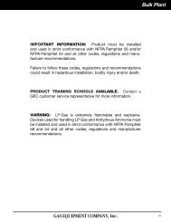
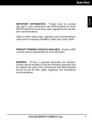
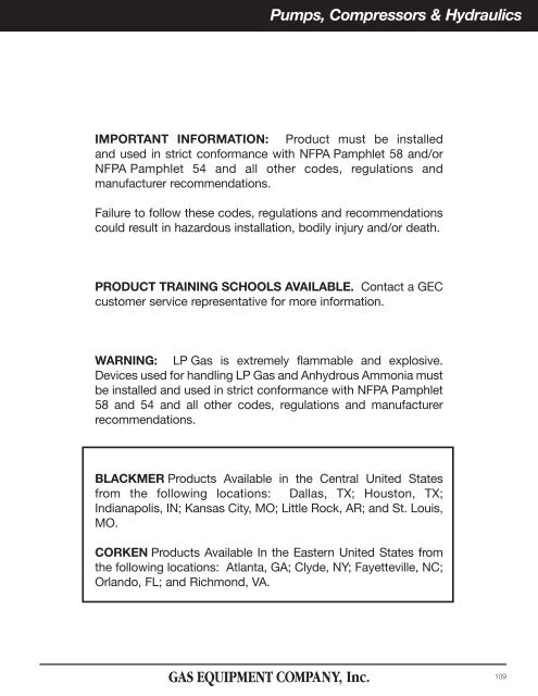
IMPORTANT INFORMATION: Product must be installed<br />
and used in strict conformance with NFPA Pamphlet 58 and/or<br />
NFPA Pamphlet 54 and all other codes, regulations and<br />
manufacturer recommendations.<br />
Failure to follow these codes, regulations and recommendations<br />
could result in hazardous installation, bodily injury and/or death.<br />
PRODUCT TRAINING SCHOOLS AVAILABLE. Contact a GEC<br />
customer service representative for more information.<br />
WARNING: LP <strong>Gas</strong> is extremely flammable and explosive.<br />
Devices used for handling LP <strong>Gas</strong> and Anhydrous Ammonia must<br />
be installed and used in strict conformance with NFPA Pamphlet<br />
58 and 54 and all other codes, regulations and manufacturer<br />
recommendations.<br />
BLACKMER Products Available in the Central United States<br />
from the following locations: Dallas, TX; Houston, TX;<br />
Indianapolis, IN; Kansas City, MO; Little Rock, AR; and St. Louis,<br />
MO.<br />
CORKEN Products Available In the Eastern United States from<br />
the following locations: Atlanta, GA; Clyde, NY; Fayetteville, NC;<br />
Orlando, FL; and Richmond, VA.<br />
109
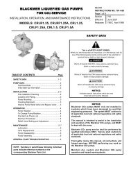
Cylinder Filling <strong>Pumps</strong><br />
Cylinder Filling <strong>Pumps</strong><br />
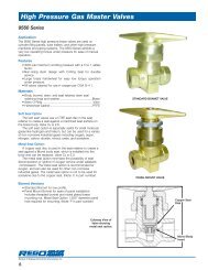
These 1" motor speed pumps have long been popular for<br />
cylinder filling, small volume motor fueling & supplying small<br />
vaporizers. They offer the same heavy-duty construction of<br />
larger Blackmer models. Available in two mounting styles &<br />
capacity ranges.<br />
C-Face Mounting — Direct Motor Drive<br />
<strong>Pumps</strong> in the LGF Series mount directly to standard C-Face,<br />
1750 rpm motors with flexible coupling. LGF1 pumps use a 1 hp<br />
motor as standard and LGF1P pumps use a 1 1 ⁄2 hp motor as<br />
standard. Standard motors for these pumps are single-phase,<br />
115/230 volt, right-hand rotation, explosion-proof construction,<br />
with automatic reset thermal overload protection. U.L. listed &<br />
suitable for continuous duty. An explosion-proof manual switch<br />
is also available for mounting either at the motor or at a remote<br />
location.<br />
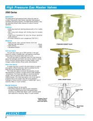
Base Mounting — Direct Motor Drive<br />
LGB1 Series pumps have brackets for foot-mounting to a conventional<br />
baseplate. The mounted pump is furnished with a<br />
flexible shaft coupling for connection to a standard motor. These<br />
units are designated as LGB1-DM or LGB1P-DM. Motors for<br />
these units are shipped to customer specifications. Coupling<br />
guard included.<br />
C-Face Mounted Style<br />
Assembled Pump Unit<br />
LGF1P<br />
DM Style<br />
Assembled Pump Unit<br />
LGB1<br />
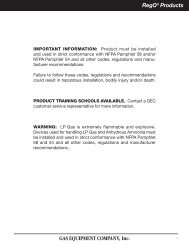
Built-In Combination Valve Eliminates<br />
Cost Of Separate Bypass Valves<br />
Built into the LGF1 & LGB1 Series pump is a patented<br />
“combination” valve acting as a back-to-tank bypass valve &<br />
as an internal relief valve. This feature lowers installation costs<br />
by<br />
eliminating the need for a separate bypass valve. It also<br />
assures pressure relief if the back-to-tank bypass line is<br />
closed. The valve’s unique three-stage operation is illustrated<br />
to the right.<br />
Normal Operation<br />
Valve completely closed<br />
during normal operation<br />
with discharge line open.<br />
Combination Relief/Bypass Valve<br />
Back-to-Tank Bypassing<br />
Discharge pressure exceeding<br />
the valve setting opens valve to<br />
second stage, returning all or<br />
part of flow back to supply tank.<br />
Pressure Relief<br />
If back-to-tank line is<br />
closed, valve opens to<br />
third stage, passing flow<br />
back to inlet side of pump.<br />
Assembled Pump Units<br />
Model<br />
#<br />
Description<br />
Factory<br />
Relief<br />
Valve<br />
Setting<br />
Pump<br />
&<br />
Motor<br />
Speed<br />
Approx. Delivery<br />
Of Propane @<br />
Diff. Pressures &<br />
Pump Speeds<br />
50 PSI<br />
Diff.<br />
100 PSI<br />
Diff.<br />
Motor<br />
Size<br />
(HP)<br />
Normal Time<br />
To Fill LP <strong>Gas</strong><br />
Cylinders<br />
(Min.)<br />
20 lb. 100 lb.<br />
Max. Diff.<br />
Pressure<br />
in PSI for<br />
Continuous<br />
Duty<br />
Rated at<br />
Shaft<br />
Size<br />
LGF1C<br />
LGF1PC<br />
LGB1C<br />
LGB1PC<br />
1" Flange Mounted<br />
C-Face Style<br />
1" Bracket Mounted<br />
DM Style<br />
105 psi<br />
120 psi<br />
105 psi<br />
120 psi<br />
1750<br />
RPM<br />
8.0<br />
6. 0<br />
(30.3) (22.7)<br />
13.0<br />
10<br />
(49.2) (37.9)<br />
8.0<br />
6. 0<br />
(30.3) (22.7)<br />
13.0 10<br />
(49.2) (37.9)<br />
1 3<br />
/4 3 105<br />
1 1 /2<br />
1 /2 2 120<br />
1 3 /4 3 105<br />
1 1 /2<br />
1 /2 2<br />
120<br />
11/16<br />
110
Cylinder Filling <strong>Pumps</strong><br />
Cylinder Filling & Motor Fuel Dispensing <strong>Pumps</strong><br />
Model C51A<br />
This unit is close-coupled to 1/2 HP 60 Hz. explosion proof<br />
motor. All are 115/230 volt and have an automatic reset<br />
overload relay and built-in switch.<br />
C10SM<br />
Ideal for those one scale bottle filling operation. Fills<br />
20# cylinders in 1 /2 minute. Fills 100# cylinders in 2 1 /2<br />
minutes and fuels through a meter at 7 GPM.<br />
C51A<br />
C12SM<br />
For those who want to do it faster. Especially recommended<br />
for motor fueling and “batch” fork lift filling. Fills 20# cylinders<br />
in 15 seconds, 100# cylinders in 2 minutes. Perfect for<br />
motor fueling through meter at 15 GPM.<br />
C10SM<br />
Pump<br />
Model<br />
Motor<br />
Only*<br />
HP<br />
Motor<br />
Specs<br />
Voltag<br />
e<br />
Phase<br />
RPM<br />
C apacity in GPM<br />
Max.<br />
Connections<br />
20 PSID<br />
50 PSID<br />
75 PSID<br />
Diff. Inlet<br />
Outlet<br />
C51A<br />
2767<br />
1<br />
/2 115/23<br />
0 S ingle<br />
1800 4.5<br />
3.<br />
25 2.<br />
75 80 1" 3<br />
/4"<br />
C10SM<br />
2555<br />
3<br />
/4 115/23<br />
0 Single<br />
3450 12 6 .5 2.5<br />
70 1 1<br />
/4" 1"<br />
C12SM<br />
2556<br />
1 † 115/23<br />
0 Single<br />
3450 19 15 11 85 1 1<br />
/2" 1"<br />
C13SM<br />
4261<br />
2 115/2<br />
30 Single<br />
3450 26 21 17 110<br />
1<br />
/2" 1"<br />
C14SM<br />
2557<br />
3 230/4<br />
60 Three<br />
3450 38 32 25 125<br />
1<br />
/2" 1"<br />
Heater<br />
Element<br />
Internal<br />
External / P28<br />
External / P32<br />
External / P36<br />
N/A**<br />
* When ordering motors only, switch box & switch are ordered separately.<br />
** Refer to Motor & Starter section for proper selection.<br />
† Rated 1.5 HP<br />
Stationary Bottle <strong>Pumps</strong><br />
Turbine pumps, motor driven or engine driven<br />
for handling high head pressure at 75 PSID.<br />
Part No. Inlet X Outlet Capacity RPM Shaft Size<br />
F10-101 1 1/4” x 1” 3 GPM<br />
F12-101<br />
12 GPM<br />
1 1/2” x 1”<br />
F14-101 25 GPM<br />
3600 1”<br />
NOTE: Motors sold separately.<br />
111
Cylinder Filling <strong>Pumps</strong><br />
Multi-Cylinder & Motor Fuel Filling <strong>Pumps</strong><br />
These motor-speed pumps offer higher capacities than the LGF1/B1<br />
Series pumps. They are suited to a variety of small transfer jobs, but<br />
are especially popular for multi-station cylinder-filling systems. They<br />
are equipped with a built-in relief valve and are fitted for both LP <strong>Gas</strong><br />
or anhydrous ammonia service. These pumps are designed for footmounting.<br />
All of the pumps are equipped with replaceable cylinder<br />
liners and end discs, permitting rebuilding of the pump to like new<br />
condition.<br />
Flange Drive Style<br />
LGLF1 1 ⁄4<br />
C-Face Mounting - Direct Motor Drive<br />
This drive is available for the LGL1 1 ⁄4 Series pumps. The pump is<br />
mounted to a steel baseplate and furnished with a flexible shaft<br />
coupling for connection to a standard motor. A coupling guard is<br />
included.<br />
Base Mounting - Direct Motor Drive<br />
This drive is available for the LGL1 1 ⁄4 & LGL1 1 ⁄2 Series pumps. The<br />
pump is mounted to a steel baseplate and furnished with a flexible<br />
shaft coupling for connection to a standard motor. A coupling guard<br />
is included.<br />
DM Drive Style<br />
LGL1 1 ⁄2<br />
Assembled Pump Units<br />
Model<br />
#<br />
Description<br />
Pump &<br />
Motor<br />
Speed<br />
RPM<br />
Approx. delivery<br />
in GPM (LPM)<br />
propane<br />
50 PSI<br />
Diff.<br />
100 PSI<br />
Diff.<br />
Motor<br />
Size<br />
HP<br />
Max. Diff.<br />
Pressure<br />
in PSI<br />
Max. Motor Size<br />
To Mount on<br />
Standard Base<br />
Shaft<br />
Size<br />
LGLF1<br />
1<br />
/4<br />
1 1 /4" - Flange<br />
or<br />
bracket mounted<br />
LGL1<br />
1<br />
/2 1 1 /2" - Bracket<br />
mounted<br />
LGLF1<br />
1 /4<br />
1 1 /4" - Flange<br />
or<br />
bracket mounted<br />
LGL1<br />
1<br />
/2 1 1 /2" - Bracket<br />
mounted<br />
1750<br />
1150<br />
21<br />
(79.5)<br />
33<br />
(124.9)<br />
13<br />
(49.2)<br />
20<br />
(75.7)<br />
18<br />
(68.1)<br />
29<br />
(109.8)<br />
10<br />
(37.9)<br />
17<br />
(64.3)<br />
2<br />
3<br />
2<br />
3<br />
150 215T<br />
7/8<br />
For Repair Parts, see back of section.<br />
112
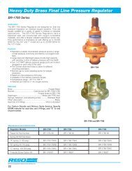
Stationary Bulk Plant <strong>Pumps</strong><br />
Multi-Purpose <strong>Pumps</strong> For Bulk Plants,<br />
Terminals & Truck Systems<br />
These workhorse pumps have long been popular for a broad<br />
range of service on bobtails, transports, vaporizers and bulk<br />
transfer service. The LGLD2 and LGLD3 are particularly suited<br />
to bobtails, because they offer a double shaft extension. This<br />
permits use of the pump by either right or left handed PTO<br />
rotation simply by reversing the position in which the pump is<br />
mounted.<br />
The LGLD2/LGLD3 pumps are designed for medium volume<br />
bulk plant service and transfer applications. They feature a<br />
single-shaft configuration - especially suited for stationary applications.<br />
Models in these series are fitted for either LP <strong>Gas</strong> or anhydrous<br />
ammonia service. All of the pumps are equipped with replaceable<br />
cylinder liners and end discs, permitting rebuilding of the<br />
pump to like new conditions.<br />
High Capacity Liquefied <strong>Gas</strong> Pump<br />
Blackmer’s LGLD4 pump is fitted with a special cavitation suppression<br />
liner for optimum performance & extended service life. UL listed for<br />
handling butane, propane & anhydrous ammonia, this durable pump is<br />
ideal for rapid loading & unloading of transports and bobtails or bulk plant<br />
service. Flow rates range from 130 to 270 GPM with differential pressures<br />
up to 125 psi.<br />
LGLD2 & LGLD3 <strong>Pumps</strong><br />
Capacity Range: 18 to 140 GPM<br />
V-Belt Drive Style <strong>Pumps</strong><br />
These units have high torque V-belts and quick disconnect<br />
sheaves. Sheaves are thinner, which puts<br />
them closer to the bearings, reducing the stress on<br />
both motor and pump shafts. Sheaves and hubs are<br />
a two-part assembly that comes apart easily. Units<br />
come complete with belt guard pump mounted to<br />
base plate, and a motor.<br />
Model #<br />
Size<br />
RPM<br />
GPM*<br />
HP*<br />
Max. Diff.<br />
Pressure<br />
420<br />
40<br />
3<br />
LGLD2E<br />
2"<br />
520<br />
50<br />
640<br />
65<br />
420<br />
80<br />
5<br />
150 PSI<br />
LGLD3E<br />
3"<br />
520<br />
108<br />
7.5<br />
640<br />
133<br />
420<br />
170<br />
10<br />
LGLD4<br />
3" V-Belt Drive<br />
LGLD3-VB-10HP<br />
LGLD4A<br />
4"<br />
520<br />
220<br />
15<br />
125 PSI<br />
640<br />
270<br />
20<br />
* Differential Pressure = 50 psi<br />
NOTE: Delivery depends on system design, pipe sizing and valve capacity.<br />
Liquid Transfer Assembly<br />
Pre-plumbed “Loop” Bobtail-Truck-Storage loading and transport<br />
unloading. Available with 2" or 3" pumps. Approximate<br />
GPM are 50, 120, and 250 respectively 2”, 3”, and 4”.<br />
Part #<br />
Pump<br />
Size<br />
Capacity<br />
LGLD2-VB-NH<br />
2" 55 gpm<br />
LGLD3-VB-NH<br />
3" 112 gpm<br />
LGLD4-VB-NH<br />
4" 220 gpm<br />
Please specify size and phase of explosion proof motor.<br />
NOTE: Capacity calculated using 100 PSI differential at 640 RPM..<br />
LGL3-VB-NH<br />
113
Stationary Bulk Plant <strong>Pumps</strong><br />
Coro-Vane Stationary Pump<br />
Sliding vane pumps for bulk plant installations.<br />
Part No. Flange Size Capacity<br />
521-103 2” 95 GPM<br />
521-103 2-1/2” 95 GPM<br />
1021-103* 3” 165 GPM<br />
1021-103* 4” 165 GPM<br />
Z4500 4” x 3” 350 GPM<br />
NOTE: Pump capacity shown are only approximate and will vary depending<br />
on motor horsepower, RPM, differential pressures and piping.<br />
Motors sold separately. See page 148.<br />
Coro-Vane Stationary Pump Selection for LP-<strong>Gas</strong> Bulk Plant<br />
Pump<br />
Model<br />
Pump<br />
RPM<br />
GPM at<br />
20 PSI<br />
* Will be replaced by Z3500 Series in 2006.<br />
Horse<br />
Power<br />
Phase<br />
Frame<br />
Size<br />
Suggested Pipe Size<br />
Inlet<br />
1<br />
/2"<br />
1<br />
/2"<br />
Outlet<br />
Vapor<br />
By-Pass<br />
Valve<br />
Liquid<br />
Hose Size<br />
521-103-1<br />
780<br />
70 5 3 184T<br />
2 2" 1 1<br />
/4" 1 1<br />
/4" 1 1<br />
/2" 1"<br />
521-103-2<br />
780<br />
70 5 1 215T<br />
2 2" 1 1<br />
/4" 1 1<br />
/4" 1 1<br />
/2" 1"<br />
1021-103-1*<br />
640<br />
125<br />
5 3 184T<br />
3" 3" 1 1<br />
/4" 2" 2" 1 1<br />
/4"<br />
1021-103-2*<br />
640<br />
125<br />
5 1 215T<br />
3" 3" 1 1<br />
/2" 2" 2" 1 1<br />
/4"<br />
1021-103-3*<br />
780<br />
165<br />
7 1<br />
/2 3 213T<br />
3" 3" 1 1<br />
/2" 2" 2" 1 1<br />
/4"<br />
Z4500 640<br />
260<br />
10 3 215T<br />
4" 4" 2" 2" 2" 1 1<br />
/2"<br />
Z4500 780<br />
325<br />
15 3 254T<br />
4" to 6" 4" 2" 2" 2" 1 1<br />
/2"<br />
Vapor<br />
SC-Series Side Channel Pump<br />
Side Channel pumps are used in LPG applications where high differential<br />
pressure is necessary or low NPSH conditions exist, such as pumping<br />
from underground tanks, the SC-Series multistage side-channel is the<br />
pump of choice.<br />
The Side Channel pump is offered in six different sizes, each ranging from<br />
one to eight stages. This provides for a wide range of pressures,<br />
capacities, and liquid transfer rates.<br />
The Corken SC-Series pump line utilizes an integral centrifugal and side<br />
channel design to create flow characteristics which enable the pump to<br />
handle up to 50% vapor and low NPSH conditions. The multi-stage<br />
modular side channel design which features one to eight open radial-vane<br />
impellers is capable of building differential pressures of over 200 psi. The<br />
Side Channel pump casing comes standard as Ductile Iron with an option<br />
of Stainless Steel. The impeller material comes standard as Brass but can<br />
be ordered as either Steel or Stainless Steel.<br />
SC Series Side Channel Pump<br />
Model # Description Inlet Flange Outlet Flange<br />
RPM (50 Hz)<br />
RPM (60 HZ)<br />
Max. Working<br />
Pressure PSIG<br />
Differential<br />
Pressure<br />
Range PSI<br />
SC-10 1-1/2" 3 / 4 " 10 - 150<br />
SC-20 2-1/2" 1-1/4" 15 - 230<br />
SC-30 Multistage 2-1/2" 1-1/4" 1450<br />
10 - 180<br />
Side Channel<br />
580<br />
SC-40 3 " 1-1/2" 1750<br />
<strong>Pumps</strong><br />
10 - 175<br />
SC-50 4 " 2 " 10 - 210<br />
SC-60 4 " 2-1/2" 10 - 250<br />
114
Truck <strong>Pumps</strong><br />
Blackmer Flange Mounted <strong>Pumps</strong> for<br />
Bobtails and Transports<br />
For Bobtail Service<br />
The TLGLF3 pump series flange mounts directly to the truck<br />
tank in combination with a flanged internal control valve.<br />
Because it eliminates the intake line and related restrictions to<br />
flow, it also eliminates the vaporization problem caused by<br />
them. That means longer pump life and higher effective pump<br />
capacity. The pump is rated to 125 psi differential.<br />
The TLGLF3 pump is suitable for both LP <strong>Gas</strong> and anhydrous<br />
ammonia. A double shaft extension is standard, making the<br />
pump suitable for either right or left-hand PTO rotation. The<br />
pumps is equipped with replaceable cylinder liners and end<br />
discs, permitting rebuilding of the pump to like-new conditions.<br />
For Transport Service<br />
The TLGLF4 series transport pump is designed to mount to<br />
4" internal valves. It is suitable for both LP <strong>Gas</strong> and anhydrous<br />
ammonia service. Ideal intake conditions assure<br />
maximum pumping rates and the shortest possible transport<br />
turnaround time. An auxiliary intake port next to the mounting<br />
flange can be used for emergency unloading of another tank<br />
or transport. Rated for differential pressures to 125 psi, the<br />
pump has twin discharge ports which permit the use of two<br />
hoses, if necessary to reduce pressure loss when unloading<br />
into restrictive receiving systems.<br />
Model # Description Suction Flange<br />
Discharge<br />
Flange<br />
TLGLF3C Flange<br />
3" 300# ANSI 2" NPT<br />
TLGLF4A Mounted 4" 300# ANSI 2" NPT<br />
Pump<br />
Speed<br />
RPM<br />
Max.<br />
Working<br />
Pressure<br />
650 350<br />
Max.<br />
Differential<br />
Pressure<br />
150 psid<br />
TLGLF3 <strong>Pumps</strong><br />
Capacity range:<br />
45 to 90 GPM<br />
TLGLF4 <strong>Pumps</strong><br />
Capacity range:<br />
130 to 270 GPM<br />
Bypass Valves<br />
Model #<br />
Common<br />
Applications<br />
Used With<br />
Blackmer<br />
Pump Model<br />
Ports<br />
Max. Rated Flow* - GPM (LPM) @<br />
20 PSI 50 PSI<br />
80 PSI<br />
120 PSI<br />
BV-034<br />
BV-100<br />
Cylinder-Filling Systems<br />
1 1 /4" or 1 1<br />
/2"<br />
Either valve<br />
3<br />
/4"<br />
NPT<br />
Tapped<br />
1" NPT<br />
Tapped<br />
25<br />
(95)<br />
40<br />
(151)<br />
50<br />
(189)<br />
60<br />
(227)<br />
BV-114<br />
BV-112<br />
Bobtail Trucks &<br />
Smaller Bulk Plant Systems<br />
2" or 3"<br />
Either valve<br />
1 1 /4"<br />
NPT<br />
Tapped<br />
1 1 /2"<br />
NPT<br />
Tapped<br />
60<br />
(227)<br />
80<br />
(303)<br />
100<br />
(379)<br />
125<br />
(473)<br />
BV-200<br />
Transports or<br />
Larger Bulk Plant Systems<br />
3" & 4"<br />
2" NPT<br />
Companion Flanges<br />
150<br />
(568)<br />
180<br />
(681)<br />
220<br />
(883)<br />
250<br />
(946)<br />
* Normal maximum bypass flow rates without significantly exceeding the set<br />
pressure limit.<br />
BV 3 ⁄4/BV1<br />
BV2<br />
BV1 1 ⁄ 2 cutaway<br />
115
Truck <strong>Pumps</strong><br />
Coro-Vane Truck <strong>Pumps</strong><br />
These units have high torque V-belts and quick disconnect<br />
sheaves. Sheaves are thinner, which puts them closer to the<br />
bearings, reducing the stress on both motor and pump shafts.<br />
Sheaves and hubs are a two-part assembly that comes apart<br />
easily. Units come complete with belt guard pump mounted to<br />
base plate, and a motor.<br />
Z2000<br />
Model # Description Suction Flange<br />
Discharge<br />
Flange Max. RPM<br />
Max. Working<br />
Pressure<br />
Max.<br />
Differential<br />
Pressure<br />
Z2000 2" NPT 2" NPT<br />
Z3200 3" 300# ANSI 2" EII<br />
Z4200<br />
Coro-Vane<br />
Truck <strong>Pumps</strong><br />
4" 300# ANSI 2" Dual NPT 800 400 psig 125 psid<br />
Z3500*<br />
3" NPT 3" NPT<br />
Z4500<br />
4" 300# ANSI 3" ANSI<br />
Z3200<br />
* Replaces Model # 1022E.<br />
Z3500<br />
Z4500<br />
Z4200<br />
Corken By-Pass Valves<br />
Model #<br />
Description<br />
Common<br />
Applications<br />
Ports<br />
Flow Rate<br />
(GPM)<br />
B166-12 Automatic Dual-Purpose<br />
3/4" NPT Up to 30<br />
Cylinder Filling Systems<br />
B166-16 By-Pass Valve<br />
1" NPT Up to 40<br />
T166-20 Bobtail Trucks & Smaller Bulk Plant 1-1/4" NPT Up to 80<br />
Pump Flow Control Valve<br />
T166-24 Systems<br />
1-1/2" NPT Up to 100<br />
Transports or Large Bulk Plant<br />
ZV200 Differential By-Pass Valve<br />
2" NPT Up to 250<br />
Systems<br />
Standard O'Ring Material: Buna N<br />
Optional O'Ring material includes: Neoprene®1, Teflon®1, Viton®1, Ethylene-Propylene*<br />
NOTE: By-Pass valves are NOT preset. Refer to Corken's installation instruction manual for proper setting procedures.<br />
116
Selection Guide<br />
Coro-Vane Selection Guide<br />
Z2000 Coro-Vane ® Truck Pump<br />
Pump Differential Approximate Delivery Brake hp Pump Torque<br />
Speed Pressure of Propane 1 Required Required<br />
RPM psi (kPa) gpm (L/min) bhp (kW) ft•lb (N•M)<br />
750 50 (345) 82 (309) 2.9 (2.2) 20.4 (27.7)<br />
750 100 (689) 77 (291) 5.8 (4.3) 40.8 (55.3)<br />
650 50 (345) 69 (261) 2.5 (1.9) 20.4 (27.7)<br />
650 100 (689) 64 (242) 5.1 (3.8) 40.8 (55.3)<br />
600 50 (345) 63 (238) 2.3 (1.7) 20.4 (27.7)<br />
600 100 (689) 58 (219) 4.6 (3.5) 40.8 (55.3)<br />
500 50 (345) 52 (197) 1.9 (1.4) 20.4 (27.7)<br />
500 100 (689) 46 (174) 3.9 (2.9) 40.8 (55.3)<br />
Z3200 Coro-Vane ® Truck Pump<br />
Pump Differential Approximate Delivery Brake hp Pump Torque<br />
Speed Pressure of Propane 1 Required Required<br />
RPM psi (kPa) gpm (L/min) bhp (kW) ft•lb (N•M)<br />
750 50 (345) 112 (424) 6.2 (4.6) 43.4 (58.9)<br />
750 100 (689) 99 (375) 9.9 (7.4) 69.3 (94.0)<br />
650 50 (345) 95 (360) 5.2 (3.9) 42.0 (57.0)<br />
650 100 (689) 84 (318) 8.2 (6.1) 66.3 (89.9)<br />
600 50 (345) 86 (326) 5.0 (3.7) 41.3 (56.0)<br />
600 100 (689) 76 (288) 7.8 (5.9) 64.8 (87.9)<br />
500 50 (345) 70 (265) 3.8 (2.8) 39.9 (54.1)<br />
500 100 (689) 62 (235) 5.8 (4.3) 60.9 (82.6)<br />
Z4200 Coro-Vane ® Truck Pump<br />
Pump Differential Approximate Delivery Brake hp Pump Torque<br />
Speed Pressure of Propane 1 Required Required<br />
RPM psi (bar) gpm (L/min) bhp (kW) ft•lb (N•M)<br />
750 50 (345) 369 (1397) 12.5 (9.3) 87 (118.0)<br />
750 100 (689) 325 (1230) 25.1 (18.6) 175 (237.3)<br />
650 50 (345) 316 (1196) 10.8 (8.0) 87 (118.0)<br />
650 100 (689) 278 (1052) 21.7 (16.1) 175 (237.3)<br />
600 50 (345) 289 (1094) 9.9 (7.3) 87 (118.0)<br />
600 100 (689) 254 (961) 20.0 (14.8) 175 (237.3)<br />
500 50 (345) 236 (893) 8.3 (6.2) 87 (118.0)<br />
500 100 (689) 208 (787) 16.7 (12.4) 175 (237.3)<br />
1<br />
The chart shows approximate delivery rates as seen in<br />
vapor equalized propane systems at 70°F (21°C) with no<br />
pressure loss in pump suction piping. The following will<br />
cause increased vaporization of the liquid in the pump<br />
suction, adversely affecting the delivery.<br />
1. Restrictions in the suction piping such as internal valves,<br />
excess flow valves, elbows, etc...<br />
2. Restriction or lack of a vapor return line.<br />
3. Temperatures below 70°F (21°C).<br />
This loss of delivery is not caused by the pump but is a<br />
result of the natural thermodynamic properties of liquified<br />
petroleum gases. See the GUIDE TO CORKEN LIQUIFIED<br />
GAS TRANSFER EQUIPMENT CP226 for a complete<br />
description of these phenomena.<br />
117
Pump System Troubleshooting Guide<br />
➝<br />
Introduction<br />
Most LP <strong>Gas</strong> & anhydrous systems use pumps to move liquid from<br />
one location to another. Unloading transport trailer tanks into plant<br />
storage, loading delivery trucks, filling bulk tanks, engine fuel tanks,<br />
portable cylinders, etc. & pressurizing LP <strong>Gas</strong> vaporizers are only a<br />
few applications. A well-designed & properly installed pumping<br />
system will perform well for some time, but eventually problems occur<br />
requiring attention.<br />
Determining the problem and fixing it will take time and be confusing,<br />
unless one knows clearly how to proceed. The purpose of this<br />
technical guide is to provide simple, guidelines for correcting LP <strong>Gas</strong><br />
& anhydrous ammonia pumping difficulties.<br />
The procedure includes a preliminary checklist to help find out if the<br />
problem can be fixed without taking anything apart. Then, it shows<br />
how to zero in on more serious problems by using a few pressure<br />
gauges to pinpoint the cause.<br />
Before trouble occurs, equip the pumping system for easy pressure<br />
gauge installation. Small manual shutoff valves can be installed at<br />
proper locations, with plugs inserted in the outlets. This allows simple<br />
placement of pressure gauges without removing the LP <strong>Gas</strong> or anhydrous<br />
ammonia from the system at the time trouble occurs, saving a<br />
lot of time and money. Pressure gauges should be installed temporarily<br />
when the system is first installed, and pressure readings recorded<br />
while the system is working properly. Then, in many cases, comparing<br />
pressures with original readings may tell what the trouble is.<br />
NOTE: Figure 1 shows where pressure gauges should be installed and<br />
provides blank spaces to record pressure gauge readings from the<br />
original tests.<br />
The pressure gauges should not be used continuously, because vibrations<br />
and the ravages of weather cause their damage or ruin. Therefore,<br />
as soon as the initial tests are complete, it is best to close the<br />
shutoff valves, remove the gauges, plug the valves and keep the<br />
gauges in a safe place, ready for troubleshooting when really needed.<br />
Diagnosing a problem is easier if the original test results are available,<br />
but not essential. It requires more time and effort.<br />
Be sure to obtain and keep available for quick referral the Manufacturer’s<br />
Operation and Service Manuals for the valves, pump, meter and all<br />
operating equipment in the system. To avoid delays, maintain a<br />
complete stock of recommended spare parts on hand for quick<br />
repairs.<br />
Follow the steps as shown. Don’t assume the answer is known<br />
beforehand, or skip any applicable steps. Rather, be thorough and methodical,<br />
and in most instances, you will solve the problem. On the<br />
other hand, if you have done all of this and still haven’t worked out your<br />
problem, feel free to call <strong>Gas</strong> <strong>Equipment</strong> <strong>Company</strong> or Engineered<br />
Controls International, <strong>Inc</strong>. direct. We will do our best to help. Perhaps,<br />
between us, we will be able to solve your problem and add something<br />
new to the procedure which could help everyone in the future.<br />
Pump System Schematic<br />
Supply tank pressure - psig<br />
P 1<br />
P 2<br />
P 3<br />
P 4<br />
Supply tank<br />
Meter pressure<br />
Pump inlet pressure - psig<br />
Bypass Valve<br />
Pump Outlet<br />
Pressure–PSIG<br />
Hose<br />
➝<br />
Tank pressure<br />
P 1 doesn’t change<br />
A<br />
Pump<br />
Meter Assembly<br />
Vapor Eliminator<br />
Meter Chamber<br />
Differential Valve<br />
The trouble is most likely in the inlet line. It could be:<br />
1. The pump may be running at a speed too low to develop differential pressure.<br />
2. An inlet strainer is clogged.<br />
3. A valve is partially closed somewhere in the inlet time.<br />
4. Ice has formed either in the bottom of the supply tank or somewhere in the inlet line. This is<br />
common particularly when the tank has been hydrostatically tested or purged with steam & not<br />
completely drained & dehydrated.<br />
5. If a Flomatic valve is used, it may not be opening for a number of reasons:<br />
a) Pressure in the tank to be filled may be considerably less than that in the supply tank,<br />
making it impossible for the pump to develop sufficient differential pressure to open the<br />
valve (simply throttle a manual valve on the discharge line to cause the pump to develop<br />
enough differential pressure to open the Flomatic valve. As the pressure in the tank to be<br />
filled goes up, it will be possible to re-open the valve in the discharge line.)<br />
b) The pump by-pass valve may be blocked open or have broken or damaged parts,<br />
preventing the pump from developing sufficient differential pressure to open the Flomatic<br />
valve. (Pump outlet pressure must rise at least 21 PSI to open the Flomatic valve.)<br />
c) The Flomatic strainer, filter, three-way valve or other element in the actuating line is clogged,<br />
or the activating line is kinked.<br />
d) The Flomatic valve internal parts may be damaged or worn. (Refer to Rego installation<br />
manual #A7884F-301 for flanged valves or #L-451 for diaphragm-type threaded valves for<br />
repair instructions.)<br />
6. If an internal valve is used, the main valve may not be opening due to insufficient equalization time,<br />
broken or damaged valve parts, valve lever in closed position or insufficient excess flow sizing.<br />
NOTE: Meter pressure is not needed for this condition.<br />
➝<br />
➝<br />
P 2<br />
Pump inlet<br />
pressure decreases<br />
P 1<br />
Pump outlet<br />
pressure<br />
doesn’t change<br />
➝<br />
P 1<br />
Tank pressure<br />
doesn’t change<br />
Tank To Be Filled<br />
➝<br />
B<br />
P 2<br />
Pump inlet<br />
pressure<br />
doesn’t change<br />
The trouble is most likely related to the pump or<br />
by-pass valve. It could be:<br />
1. The pump may have excessively worn parts.<br />
2. The internal by-pass valve in the pump may be<br />
blocked open by foreign material, or may have broken<br />
or damaged parts.<br />
3. The back-to-tank by-pass valve may be blocked open by<br />
foreign material or may have broken or damaged parts.<br />
4. The manual by-pass valve, if so equipped, may be open.<br />
NOTE: Meter pressure is not needed for this condition.<br />
P 3<br />
Pump outlet<br />
pressure goes<br />
up a little<br />
118
Pump System Troubleshooting Chart<br />
Basic Assumption<br />
The pumping system did work OK, but now the transfer rate is<br />
considerably less, or the system won’t pump at all.<br />
Preliminary Review<br />
1. Check the supply tank liquid level. The transfer rate could be considerably<br />
reduced if the level is low, due to bubbles in the line, because of insufficient liquid<br />
head, or a vortex effect in the tank. Remember, reduction in the pumping rate<br />
from these causes will be more extreme in cold weather (tank pressures are low).<br />
2. Examine the pump drive to make sure the pump is rotating properly. Inspect for<br />
loose drive belts, damaged or broken flexible couplings or universal joints,<br />
broken drive keys & damaged or inoperative power take-off or pump clutch, etc.<br />
3. If the system is equipped with the Rego Flomatic Valve.<br />
a) Three-way valve handle should be straight out, allowing the valve to open.<br />
b) Check the position indicator on the Flomatic Valve when the pump is<br />
running. If the indicator shows that the valve is open, the trouble must be<br />
downstream of the valve.<br />
c) Make sure the priming valve is open, allowing pressure to equalize between<br />
the tank and pump inlet.<br />
4. If the system is equipped with internal valves, make sure the operating lever<br />
moves to a full open position. Repair if needed.<br />
5. Make sure all valves in the system are either open or closed as required for<br />
normal operation. Check each valve in sequence, starting from the supply tank,<br />
making sure that no valve element is missed.<br />
If the cause of the problem has not been determined during preliminary review, it<br />
will be necessary to conduct diagnostic tests, using pressure gauges at key points<br />
in the system.<br />
Diagnostic Tests<br />
Open all valves as required for proper pumping operation. Gauges should<br />
show tank pressure, pump inlet pressure, pump outlet pressure and meter<br />
pressure to be equal.<br />
Start the pump and observe all pressure gauges. Match results with conditions<br />
A, B, C, or D. Follow the appropriate steps.<br />
Final Results<br />
Make repairs or adjustments as needed, and test the system’s operation.<br />
Record a new set of test pressures for future reference, and other replacements<br />
for all space parts used. The system now is ready to return to service.<br />
C<br />
D<br />
➝<br />
P 1<br />
➝<br />
P 2<br />
P 3<br />
➝<br />
P 4<br />
➝<br />
➝<br />
P 1<br />
➝<br />
P 2<br />
P 3<br />
➝<br />
➝<br />
P 4<br />
Tank pressure<br />
doesn’t change<br />
Pump inlet<br />
pressure<br />
doesn’t change<br />
Pump outlet<br />
pressure rises<br />
substantially<br />
Meter pressure<br />
rises substantially<br />
The trouble is most likely in the meter vapor eliminator or meter differential<br />
valve. It could be:<br />
1. The meter’s vapor eliminator may be malfunctioning. If the valve at the<br />
outlet of the vapor eliminator does not seat when the vapors have been<br />
purged, the differential valve downstream of the meter will not open. Such<br />
failure could be caused by a damaged vapor eliminator valve seat, foreign<br />
material blocking the vapor eliminator valve, a leak in the ball float, or a<br />
jammed or binding linkage between the ball and valve.<br />
2. The diaphragm could be ruptured, or other parts could be damaged or broken<br />
in the differential valve downstream of the meter.<br />
Tank pressure<br />
doesn’t change<br />
Pump inlet<br />
pressure doesn’t<br />
change<br />
Pump outlet<br />
pressure rises<br />
substantially<br />
Meter pressure<br />
doesn’t change<br />
The problem is probably downstream of the pump. Look for a closed valve,<br />
or some type of blockage in the discharge line. It could be:<br />
1. The meter strainer may be clogged.<br />
2. A back check valve at the inlet of the meter may be blocked, closed, or jammed.<br />
3. The meter rotor may be jammed by foreign material, preventing it from moving<br />
properly, which would prevent or retard flow.<br />
4. The drive key on the meter gears may be sheared. (In this case, flow would<br />
actually be moving through the meter but not registering.)<br />
5. The differential valve downstream of the meter may be closed due to damage,<br />
foreign material or ice.<br />
6. If screw type hose fittings are used, it is extremely important that they be<br />
installed properly. If not, it is possible that a flap of rubber may be cut from<br />
the inside diameter of the hose, acting as a back check. It can flap across the<br />
discharge line, effectively stopping the flow.<br />
7. Check the hose nozzle valve, if so equipped. In some brands, a bent handle<br />
or other defect may prevent the inner valve from opening sufficiently to allow<br />
a proper amount of flow.<br />
8. The problem could be in the valve assemblies in the tank to be filled. If you<br />
are dealing with a delivery truck application, move to another tank and see<br />
whether the problem still exists. If not, it may be a problem with one specific<br />
tank, rather than the pumping system.<br />
9. Some delivery trucks are equipped with a quick-acting valve immediately<br />
upstream of the hose reel. Make sure that this valve is open.<br />
10.Some delivery trucks are equipped with excess flow valves between the<br />
meter & hose reel. Improper sizing, a weak spring, or other valve damage can<br />
cause this valve to close prematurely, effectively stopping the flow.<br />
11.If, with a delivery truck system, the flow reduced considerably while the tank<br />
is being filled, it is possible that the back-to-tank by-pass valve is not set high<br />
enough to compensate for vapor pressure buildup in the tank being filled. This<br />
can be solved merely by adjusting the by-pass valve at a slightly higher level.<br />
WARNING: Do not raise the back-to-tank by-pass setting high enough to cause<br />
the internal relief valve in the pump to actuate. Excessive cavitation, loss of<br />
capacity and premature pump wear can occur.<br />
Final Results<br />
Make repairs or adjustments as needed, and test the system’s operation.<br />
Record a new set of test pressures for future reference, and other replacements<br />
for all space parts used. The system now is ready to return to service.<br />
119
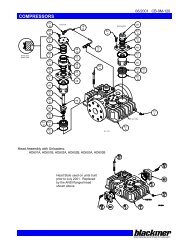
Pump Repair<br />
Models: LGF1E, LGB1E, LGF1PE & LGB1PE<br />
153<br />
LOCKNUT TOOL<br />
Ref.<br />
No.<br />
Description<br />
Parts<br />
per<br />
Pump<br />
Part No.<br />
Ref.<br />
No.<br />
Description<br />
Parts<br />
per<br />
Pump<br />
4<br />
4<br />
4<br />
Part No.<br />
2 Adjusting Screw – Relief Valve (R/V) 1 432901 28 † Capscrews – Bearing Cover 920080<br />
3 Locknut – Adjusting Screw 1 922811 28A † Bracket Mounting Screws 920090<br />
4 Cover – R/V 1 412901 28B † Bracket Mounting Screws 920101<br />
4A O-Ring – Spring Guide 1<br />
1 711940 28C Guard Screw 1 920026<br />
7 Spring Guide – R/V 1 422901 Coupling Half – Pump 906150<br />
8 Spring – R/V 1 472901 Coupling Half – Motor (56C) 906151<br />
9 Valve – R/V 1 452901<br />
34 Coupling Half – Motor<br />
1<br />
(143-145TC/184C)<br />
906147<br />
9A Disc – R/V 1 442901 Coupling Spider<br />
906155<br />
10 O-Ring – R/V Cover<br />
1<br />
1 701965 35 Key – Shaft 1<br />
1 909126<br />
12 † Cylinder – LGF1, LGB1 022914 72 O-Ring – Head 1<br />
711941<br />
1<br />
Cylinder – LGF1P, LGB1P<br />
022915 73 Gage Plug (1/4”) 2 908198<br />
13<br />
2<br />
Rotor & Shaft Assembly, Six Vane<br />
73A † Gage Plug (3/4”) 1 908225<br />
1 262901<br />
(<strong>Inc</strong>ludes Ref. Nos. 24A & 24B)<br />
76 Grease Fitting 2 317815<br />
14<br />
3<br />
Vane – Duravane (Std.) 4<br />
1 092912 76A Grease Relief Fitting 2 701992<br />
20 † Head 1 032905 104 Grease Seal 1<br />
1 331934<br />
21 Capscrews – Head 4 920178 Bracket - (base mount) - LGB1(P)D 832913<br />
24 Ball Bearing<br />
2<br />
1 903405<br />
108 Bracket (C-faced footless) - LGF1(P)D 1<br />
832912<br />
24A Locknut – Bearing 2 903531 108A Capscrews – Bracket 4 920331<br />
24B Lockwasher – Bearing 2<br />
1 903532 108B Bracket (C-faced footed)<br />
1 833000<br />
26 † <strong>Gas</strong>ket – Bearing Cover<br />
1<br />
1 383075 186 Guard 1 804120<br />
27 † Bearing Cover 1 043071 Tool - Locknut 903090<br />
153 Mechanical Seal Assembly 2<br />
1<br />
332930<br />
Kit - Maintenance (4-Vane) 898916<br />
Kit - Maintenance (6-Vane) 898994<br />
1<br />
<strong>Inc</strong>luded in Maintenance Kit. 2 Discontinued 'D' and 'C' models shipped with a 4-vane rotor. The current 6-vane rotor is fully interchangeable as<br />
long as the slotted vanes (pn 092913) are used. 3 The current slotted vanes (pn 092913) may be used in either the 6-vane or 4-vane rotors.<br />
The discontinued solid vanes may be used in the 4-vane rotors ONLY. Always install the vanes with the slot facing the direction of rotation.<br />
Ü To fit the LGB1(P)C, LGF1(P)C use: Ref. No. 12-022902/022911 respectively, Ref. No. 20-032902, Ref. No. 26-382901, Ref. No. 27-042901,<br />
Ref. No. 28-920203, Ref. No. 28A & B-920230, Ref. No. 73A-908198, and Ref. No.108-832901/832905 respectively.<br />
Keep this parts list with Installation, Operation and Maintenance Instructions.<br />
120
Pump Repair<br />
Models: LGRL1.25, LGRLF1.25A, LGL1.25, LGLF1.25A, LGL1.25 & LGLF1.5A<br />
4-Vane Rotor<br />
LOCKNUT TOOL<br />
Ref.<br />
No.<br />
Description<br />
Parts<br />
per<br />
Pump<br />
1<br />
1<br />
1<br />
1<br />
1<br />
Part No.<br />
Ref.<br />
No.<br />
Description<br />
Parts<br />
per<br />
Pump<br />
Part No.<br />
1 Cap – Relief Valve (R/V) 413200 Liner – LGRL(F)1.25 [8 - Vane Only] 183019<br />
2 Adjusting Screw – R/V 433909 41 Liner – LGL(F)1.25 [8 - Vane Only] 1<br />
2<br />
183020<br />
3 Locknut – Adjusting Screw 922923 Liner – LGL(F)1.5 [8 - Vane Only]<br />
2<br />
183310<br />
4 Cover – R/V 413076 Liner – LGRL(F)1.25 [4 - Vane Only]<br />
2<br />
183003<br />
7 Spring Guide – R/V 423955 41A Liner – LGL(F)1.25 [4 - Vane Only] 1<br />
2<br />
183004<br />
8 Spring – R/V (81 – 125 psi) 1 471428 Liner – LGL(F)1.5 [4 - Vane Only]<br />
2<br />
183301<br />
9<br />
Valve - R/V (Std.) 453077 71 Disc 2<br />
063075<br />
1<br />
Valve - R/V (Nickel Plated)<br />
452300 72 O-Ring – Head 2<br />
701918<br />
10 O-Ring – R/V Cover 1<br />
1 711924 73 Gage Plug (1/4”) 1 908198<br />
12<br />
Casing (1.25) 013075 73A Gage Plug (3/4”) 1 908225<br />
1<br />
Casing (1.5)<br />
013376 74 Setscrew – Liner 1 922088<br />
13<br />
Rotor & Shaft Assembly, Eight Vane<br />
2<br />
76 Grease Fitting 2 317815<br />
1 262300<br />
(<strong>Inc</strong>ludes Ref. Nos. 24A & 24B)(Std.)<br />
76A Grease Relief Fitting 2 701992<br />
13A<br />
1<br />
Rotor & Shaft Assembly, Four Vane<br />
2<br />
Push Rod – LGRL(F)1.25 123004<br />
1 263076<br />
1<br />
(<strong>Inc</strong>ludes Ref. Nos. 24A & 24B)<br />
77 Push Rod – LGL(F)1.25 0-2 123076<br />
14 Vane – Duravane 4-8<br />
1 093088 Push Rod LGL(F)1.5<br />
1<br />
123401<br />
20 Head 2 033073 88 O-Ring – R/V Cap 1<br />
1 701949<br />
21 Capscrews – Head 16 920276 104 Grease Seal 1<br />
1 331927<br />
24 Ball Bearing<br />
2<br />
1 903114 Tool - Locknut 903090<br />
24A Locknut – Bearing 2<br />
2<br />
903534 153 Mechanical Seal Assembly 2<br />
1<br />
333045<br />
24B Lockwasher – Bearing<br />
2<br />
1 903533 Kit - Maintenance<br />
26 <strong>Gas</strong>ket - Bearing Cover 3 2<br />
383075 LG(R)L(F)1.25(A) / 1.5(A) [8 Vane]<br />
898976<br />
27 Bearing Cover – Inboard 5 0-1 043070<br />
27A Bearing Cover – Outboard 1 043071<br />
28 Capscrews – Bearing Cover 4 4 - 8 920080<br />
35 Shaft Key 1<br />
1 909125<br />
1 <strong>Inc</strong>luded in Maintenance Kits and Rebuild Kits<br />
2 <strong>Inc</strong>luded in Rebuild Kits.<br />
2<br />
Note: Earlier model pumps used taper pins, which are no longer required.<br />
Ref. No. 73A: Earlier versions of these pumps may use a 1/4" plug (pn 908198) or 1/2" plug (pn 908215).<br />
Keep this parts list with Installation, Operation and Maintenance Instructions.<br />
The following applies to LG(R)LF pump models only:<br />
3 Use one outboard<br />
4 Use four outboard<br />
5 Use none.<br />
121
Pump Repair<br />
Models: LGL2D, TLGLD2D, LGL3C & TLGLD3C - Obsolete<br />
Discontinued models, limited parts<br />
44<br />
42 42A<br />
14<br />
73<br />
153<br />
27<br />
24 24A<br />
76<br />
28<br />
76A<br />
74<br />
71 41<br />
153<br />
76<br />
24A 24<br />
27A<br />
28<br />
20<br />
76A 26 21<br />
123A<br />
24B<br />
104<br />
35<br />
72<br />
12<br />
42A<br />
42<br />
44<br />
13<br />
9<br />
8<br />
10<br />
4<br />
166<br />
5<br />
71<br />
72<br />
13A<br />
26<br />
24B<br />
21<br />
20<br />
Ref.<br />
#<br />
Part Name<br />
Parts<br />
Per Pump<br />
2"<br />
Part #<br />
3"<br />
Part #<br />
4 Valve<br />
Cover<br />
1 414407<br />
415111<br />
5 Valve<br />
Cover Capscrews<br />
6 920316<br />
920331<br />
8 Valve Spring<br />
9 elief Valve<br />
10<br />
O” Ring, Valve Cover<br />
12<br />
asing<br />
13<br />
otor & Shaft<br />
471428<br />
471620<br />
R 454405<br />
455129<br />
“ 701919<br />
701925<br />
1<br />
C 014426<br />
015126<br />
R 264441<br />
265144<br />
13A<br />
Rotor<br />
& Double End Shaft<br />
264403<br />
265146<br />
14<br />
Vane<br />
- Duravane<br />
6 091419<br />
095131<br />
20<br />
Head<br />
2 034417<br />
035126<br />
21<br />
Head<br />
Capscrew<br />
32 - 40<br />
920351<br />
920369<br />
24<br />
Bearing<br />
903154<br />
903168<br />
24A<br />
Bearing<br />
Lockcollar<br />
701409<br />
705110<br />
2<br />
24B<br />
Lockcollar<br />
Setscrew<br />
922178<br />
922178<br />
26<br />
Bearing<br />
Cover <strong>Gas</strong>ket<br />
383940<br />
385125<br />
27<br />
B earing Cover (Outboard)<br />
1 (3)<br />
041433<br />
041817<br />
27A<br />
B earing Cover (Inboard)<br />
1 (2)<br />
041431<br />
041815<br />
28<br />
Bearing<br />
Cover Capscrew<br />
8 - 12<br />
920285<br />
920285<br />
35<br />
Shaft<br />
Key<br />
1 909130<br />
909130<br />
The following are for TLGLD2C & TLGLD3C:<br />
(1) = use one, (2) = use two, (3) = use none.<br />
Ref.<br />
#<br />
Part Name<br />
Parts<br />
Per Pump<br />
2"<br />
Part #<br />
3"<br />
Part #<br />
41<br />
Liner<br />
1 184405<br />
185111<br />
42<br />
NPT Flange<br />
654404<br />
655104<br />
Weld<br />
Flange<br />
2 654405<br />
655102<br />
42A<br />
“ O” Ring<br />
702004<br />
702002<br />
44<br />
Capscrew - NPT Flange<br />
920351<br />
920532<br />
8<br />
Capscrew - Weld Flange<br />
920351<br />
920510<br />
71<br />
Disc<br />
064413<br />
065113<br />
72<br />
Head<br />
<strong>Gas</strong>ket<br />
2 383935<br />
385107<br />
73<br />
Gage<br />
Plug<br />
908195<br />
74<br />
Liner<br />
Key<br />
1 183991<br />
185191<br />
76<br />
Grease Fitting<br />
317815<br />
317815<br />
2/set<br />
76A<br />
Grease<br />
Relief Fitting<br />
701992<br />
701992<br />
77<br />
Push<br />
Rod<br />
3 123905<br />
125105<br />
104<br />
Grease Seal<br />
331918<br />
331908<br />
1 (2)<br />
123A<br />
Dirt<br />
Shield<br />
701480<br />
—<br />
153<br />
Mechanical<br />
Seal Complete<br />
2 331417<br />
331825<br />
Some items are no longer available from Blackmer.<br />
122
Pump Repair<br />
Models: LGLD2E & LGLD3E<br />
Discontinued models: LGL2E, TLGLD2E, LGL3E & TLGLD3E<br />
LOCKNUT TOOL<br />
Ref.<br />
No.<br />
Description<br />
Parts<br />
Per<br />
Pump<br />
1<br />
Size 2<br />
Part No.<br />
Size 3<br />
Part No.<br />
Ref.<br />
No.<br />
Description<br />
Parts<br />
Per<br />
Pump<br />
Size 2<br />
Part No.<br />
2 2<br />
Size 3<br />
Part No.<br />
4 Cover - Relief Valve (R/V) 414401 415113 41 Liner 1 184405 185111<br />
5 Capscrews - R/V Cover 6 920331 920331 Flange - NPT 654401 655112<br />
42<br />
2<br />
8 Spring - R/V 1 471423 475135 Flange - Weld<br />
654405 655102<br />
9<br />
Valve - R/V (Std.) 454405 455129 42A O-Ring - Flange 2<br />
702004 1 702002<br />
1<br />
Valve - R/V (Nickel Plated)<br />
454406 455100 42B Capscrew - NPT Flange 8 920384 920547<br />
10 O-Ring - R/V Cover 1<br />
1 701919 1 701925 Capscrew - Weld Flange 920351 920510<br />
12 Casing1 014405 015127 71 Disc 2<br />
1 064412 1 065112<br />
13<br />
Rotor & Shaft Asy. - LGL<br />
72 O-Ring - Head 2<br />
702022 1 702041<br />
1 264443 265149<br />
(<strong>Inc</strong>ludes Ref. Nos. 24A & 24B)<br />
73 Gage Plug 2 908198 908198<br />
Rotor & Shaft Asy. – LGLD &<br />
74 Key - Liner † 1<br />
2, 6<br />
183991<br />
2<br />
185191<br />
13A<br />
5<br />
TLGLD<br />
1 264445 265148<br />
(<strong>Inc</strong>ludes Ref. Nos. 24A & 24B)<br />
76 Grease Fitting 2 317815 317815<br />
14 Vane - Duravane (Std.) 6<br />
1 091419 1 095131 76A Grease Relief Fitting 2 701992 701992<br />
20 Head 2 034416 035128 77 Push Rod 3<br />
1 123905 1 125105<br />
21<br />
1,<br />
Capscrews - Head (Size 2) 32 920351 N/A 104 Grease Seal 2<br />
1<br />
3 331918 1, 3 331908<br />
1,<br />
Capscrews - Head (Size 3) 40 N/A 920369 123A Dirt Shield 2<br />
1<br />
3 701480 N/A<br />
24 Ball Bearing<br />
1<br />
1 903156 1 903172 186<br />
Shaft Protector<br />
(LGLD, TLGLD Models Only)<br />
1 341601 341801<br />
24A Locknut - Bearing 2<br />
2<br />
903521<br />
2<br />
903523 Tool - Locknut 903091 903091<br />
24B Lockwasher - Bearing<br />
2<br />
1 903522 1 903524 Mechanical Seal Assembly<br />
1<br />
153 2 334439<br />
26 <strong>Gas</strong>ket - Bearing Cover 2<br />
383940 1 385125 NH 3 or Dual Service LPG (QA)<br />
335225<br />
27 Bearing Cover (Inboard) 3 1 041431 041815 Kit – Maintenance –<br />
27A Bearing Cover (Outboard) 4 1 041433 041817 NH 3 or Dual Service LPG (QA)<br />
898979 898981<br />
28 Capscrews - Bearing Cover 8 - 12 920285 920285<br />
35 Key - Shaft<br />
1<br />
1 909130 1 909130<br />
1 <strong>Inc</strong>luded in Maintenance Kit and Rebuild Kit<br />
2 <strong>Inc</strong>luded in Rebuild Kit<br />
The following applies to double end shaft pump models LGLD2E, TLGLD2E, LGLD3E & TLGLD3E: 3 Use Two<br />
4 Use None<br />
5 Double-Ended Rotor & Shaft.<br />
6 Pump models before 1995 require key 184407.<br />
Keep this parts list with Installation, Operation and Maintenance Instructions.<br />
123
Pump Repair<br />
Model: TLGLF3C<br />
LOCKNUT TOOL<br />
Ref.<br />
No.<br />
Description<br />
Parts<br />
Per<br />
Pump<br />
1<br />
Part No.<br />
Ref.<br />
No.<br />
Description<br />
Parts<br />
Per<br />
Pump<br />
Part No.<br />
4 Cover - Relief Valve (R/V)<br />
4 415108 Flange - 2" NPT 652010<br />
5 Capscrew - R/V Cover 6 920331 Flange - 2" Weld 652024<br />
8 Spring - R/V<br />
42<br />
1-2<br />
1 471428 Flanged Elbow - 2" NPT 655100<br />
Valve - R/V (Std.)<br />
451417<br />
Flanged Elbow - 2" Weld<br />
655109<br />
9<br />
1<br />
Valve - R/V (Nickel Plated)<br />
451415 O-Ring – Flange 2 1/2” x 2 3/4” 2<br />
701919<br />
10 O-Ring - R/V Cover 1<br />
42A<br />
1,<br />
701919<br />
O-Ring – Flange 2 5/8” x 2 7/8” 2<br />
702004<br />
12 Casing 1 015128 42B Capscrew - Flange, Flanged Elbow 8 920491<br />
13<br />
Rotor & Shaft Assembly<br />
(<strong>Inc</strong>ludes Ref. No. 24A & 24B)<br />
1<br />
2<br />
265147 71 Disc2<br />
1 065121<br />
14 Vane - Duravane<br />
6<br />
1 095132 72 O-Ring - Head 2<br />
1 711923<br />
20 Head 2 035132 73 Gage Plug 2 908198<br />
21 Capscrews - Head 36 920351 74 Key - Liner 1<br />
2<br />
185193<br />
24 Ball Bearing<br />
2<br />
1 903156 76 Grease Fitting 2 317815<br />
24A Locknut - Bearing 2<br />
2<br />
903521 76A Grease Relief Fitting 2 701992<br />
24B Lockwasher - Bearing<br />
1<br />
1 903522 77 Push Rod 3<br />
1 121607<br />
26 <strong>Gas</strong>ket - Bearing Cover 2<br />
1 383940 104 Grease Seal 2<br />
1 331918<br />
27 Bearing Cover 2 041431 123 Dirt Shield<br />
2<br />
1 701480<br />
28 Capscrews - Bearing Cover 8 920285 186 Shaft Protector 1 341601<br />
35 Key - Shaft<br />
1<br />
1 909130 Tool - Locknut 903091<br />
2<br />
41 Liner 1 185101 Mechanical Seal Assembly<br />
1<br />
153<br />
NH<br />
2 334439<br />
3 or Dual Service LPG (QA)<br />
<strong>Inc</strong>luded in Maintenance Kit and Rebuild Kit<br />
<strong>Inc</strong>luded in Rebuild Kit<br />
Kit – Maintenance –<br />
898980<br />
Larger O-Ring introduced October 2002<br />
NH 3 or Dual Service LPG (QA)<br />
4 Additional Parts <strong>Inc</strong>luded in Maintenance Kit with R/V<br />
Keep this parts list with Installation, Operation and Maintenance Instructions.<br />
124
Pump Repair<br />
Models: LGLD4A & LGL4A<br />
Discontinued models: LGL4 & LGLD4<br />
LOCKNUT TOOL<br />
`<br />
Ref.<br />
No.<br />
Description<br />
Parts<br />
Per Part No.<br />
Pump<br />
1<br />
1 436310<br />
1 436307<br />
1 432039<br />
1 436355<br />
1<br />
Ref.<br />
No.<br />
Description<br />
Parts<br />
Per<br />
Pump<br />
Part No.<br />
1 Cap - Relief Valve (R/V) 413952 28 Capscrews - Bearing Cover 12 920286<br />
2<br />
Adjusting Screw - R/V (LGLD4A & LGL4A) 35 Key – Shaft<br />
1<br />
1 909183<br />
Adjusting Screw - R/V (LGLD4 & LGL4)<br />
41 Liner 1<br />
2<br />
182000<br />
3<br />
Locknut - Adjusting Screw (LGLD4A & LGL4A)<br />
Flange - 3" NPT 652012<br />
Locknut - Adjusting Screw (LGLD4 & LGL4)<br />
42 Flange - 3" Weld 1 - 2 652007<br />
4 Cover - R/V 412001<br />
Flange - 4" Weld<br />
652005<br />
5 Capscrew - R/V Cover 4 920663 42A O-Ring - NPT, Weld Flange 2<br />
1 701937<br />
7 Spring Guide - R/V 1 426355<br />
Capscrew - NPT Flange 920663<br />
42B<br />
8<br />
Spring - R/V (LGLD4A & LGL4A)<br />
1 472039<br />
Capscrew - Weld Flange<br />
920640<br />
8<br />
Spring - R/V 71 Disc<br />
(LGLD4 & LGL4)<br />
1 476305<br />
2 062039<br />
9 Valve - R/V 1 452001 71A Machine Screw - Disc 8<br />
2<br />
920015<br />
10 O-Ring - R/V Cover 1<br />
701946<br />
2<br />
71B* Lockwasher - Machine Screw 8 909634<br />
Casing (LGLD4A & LGL4A)<br />
1 012009<br />
12<br />
Casing 72 O-Ring - Head 2<br />
(LGLD4 & LGL4)<br />
1 012000<br />
702039<br />
Rotor & Shaft Asy, Dbl. End –<br />
73 Gage Plug 2 908198<br />
2<br />
2<br />
LGLD4(A)<br />
262024 74 Key - Liner 1 182040<br />
13 (<strong>Inc</strong>ludes Ref. No. 24A & 24B)<br />
1<br />
76 Grease Fitting 2 317815<br />
Rotor & Shaft Asy, Sgl. End - LGL4(A)<br />
76A Grease Relief Fitting 2 701992<br />
262023<br />
(<strong>Inc</strong>ludes Ref. No. 24A & 24B)<br />
77 Push Rod 3<br />
122005<br />
14 Vane - Duravane (Std.) 6<br />
1 092019 88 O-Ring - R/V Cap 1<br />
1 701926<br />
20 Head 2 032039<br />
Grease Seal – LGLD4(A)<br />
2<br />
104<br />
21 Capscrews - Head 36 920532<br />
Grease Seal – LGL4(A) 1<br />
1 331908<br />
24 Ball Bearing<br />
2<br />
1 903172 186 Shaft Protector (LGLD4 Only) 1 341801<br />
24A Locknut – Bearing 2<br />
2<br />
903541<br />
Tool - Locknut 903092<br />
24B Lockwasher – Bearing<br />
2<br />
1 903542 Mechanical Seal Assembly 2<br />
1<br />
332050<br />
26 <strong>Gas</strong>ket - Bearing Cover 2<br />
1 385125<br />
Kit - Maintenance 898922<br />
27<br />
Bearing Cover – LGLD4(A)<br />
2<br />
Kit - Rebuild 899022<br />
041815<br />
Bearing Cover – Inboard, LGL4(A) 1<br />
27A Bearing Cover – Outboard, LGL4(A) 1 041817 153<br />
1 <strong>Inc</strong>luded in Maintenance Kit and Rebuild Kit<br />
2 <strong>Inc</strong>luded in Rebuild Kit<br />
Keep this parts list with Installation, Operation and Maintenance Instructions.<br />
125
Pump Repair<br />
Models: TLGLF4A<br />
Discontinued models: TLGLF4<br />
LOCKNUT TOOL<br />
Ref.<br />
No.<br />
Description<br />
Parts<br />
Per<br />
Pump<br />
TLGLF4A<br />
Part No.<br />
TLGLF4<br />
Part No.<br />
Ref.<br />
No.<br />
Description<br />
Parts<br />
Per<br />
Pump<br />
TLGLF4A<br />
Part No.<br />
TLGLF4<br />
Part No.<br />
1 Cap - Relief Valve (R/V) 1 413952 413952 42A O-Ring - Flange 1 701937 701937<br />
2 Adjusting Screw - R/V 1 436310 436307 Capscrew - 3" NPT Flange 920663 920663<br />
3 Locknut - Adjusting Screw 1 432039 436355<br />
42B Capscrew - 3", 4" Weld Flange; 4<br />
Blank Flange<br />
920640 920640<br />
4 Cover - R/V1 1 412001 412001 TWIN DISCHARGE PORT OPTIONS<br />
5 Capscrews - R/V Cover 4 920663 920663 Flange - 2" NPT 652010 652010<br />
43<br />
2<br />
7 Spring Guide - R/V 1 426355 426355 Flange - 2" Weld<br />
652024 652024<br />
8 Spring - R/V 1 472039 472039 O-Ring - 2" Flange 2 1/2” x 2 3/4” 2<br />
701919 701919<br />
43A 1<br />
9 Valve - R/V 1 452001 452001 O-Ring - 2" Flange 2 5/8” x 2 7/8” 2 702004 702004<br />
10 O-Ring - R/V Cover 1<br />
1 701946 701946 43B Capscrew - Discharge Flange 8 920491 920491<br />
12 Casing 1 012039 012039 71 Disc 2<br />
1 062039 062039<br />
13<br />
Rotor & Shaft Asy.<br />
2<br />
2<br />
1 262024 262022 71A Machine Screw - Disc 8 920015<br />
(includes Ref. No. 24A & 248)<br />
920015<br />
14 Vane - Duravane (Std.) 6<br />
1 092019 092019 71B Lockwasher - Machine Screw 8<br />
2<br />
909634 909634<br />
20 Head 2 032039 032039 72 O-Ring - Head 2<br />
1 702039 702039<br />
21 Capscrews - Head 36 920532 920532 73 Gage Plug 2 908198 908198<br />
24 Ball Bearing 2<br />
1 903172 903172 74 Key - Liner 1<br />
2<br />
182040 182040<br />
24A Locknut - Bearing 2<br />
2<br />
903541 903523 76 Grease Fitting 2 317815 317815<br />
24B Lockwasher - Bearing 2<br />
1 903542 903524 76A Grease Relief Fitting 2 701992 701992<br />
26 <strong>Gas</strong>ket - Bearing Cover 2<br />
1 385125 385125 77 Push Rod 3<br />
1 122005 122001<br />
27 Bearing Cover 2 041815 041815 88 O-Ring - R/V Cap 1<br />
1 701926 701926<br />
28 Capscrews - Bearing Cover 12 920286 920286 104 Grease Seal 2<br />
1 331908 331908<br />
35 Key - Shaft<br />
1<br />
1 909183 909183 186 Shaft, Protector 1 341801 341801<br />
41 Liner 1<br />
2<br />
182000 182039 Tool - Locknut 903092 903091<br />
AUXILIARY INTAKE OPTIONS 153 Mechanical Seal Assembly 2<br />
1<br />
332050 332050<br />
Flange - 3" NPT 652012 652012 Kit - Maintenance 898922 N/A<br />
42<br />
Flange - 4" Weld 652005 652005 Kit - Rebuild 899022 N/A<br />
1<br />
Flange - 3" Weld 652007 652007 <strong>Inc</strong>luded in Maintenance Kit and Rebuild Kit<br />
Flange - Blank<br />
652000 652000<br />
2 <strong>Inc</strong>luded in Rebuild Kit<br />
Keep this parts list with Installation, Operation and<br />
Maintenance Instructions<br />
126
Pump Repair<br />
Models: LGL158A<br />
153<br />
Ref.<br />
No.<br />
Description<br />
Parts<br />
Per<br />
Pump<br />
Part No.<br />
Ref.<br />
No.<br />
Description<br />
Parts<br />
Per<br />
Pump<br />
Part No.<br />
4 Cover - Relief Valve (R/V) 1 415701 27 Bearing Cover 1 045701<br />
5 Capscrews - R/V Cover 4 920122 28 Capscrews - Bearing Cover 4 920122<br />
8 Spring - R/V (225 psi) 1 471400 35 Key - Shaft 1<br />
1<br />
909152<br />
9 Valve - R/V 1 455701 41 Liner 1<br />
2<br />
185701<br />
10 O-Ring - R/V Cover 1<br />
1<br />
711924 71 Disc 2<br />
1<br />
065701<br />
12 Casing 1 015701 72 O-Ring - Head 2<br />
1<br />
702169<br />
13 Rotor & Shaft Asy. 1<br />
2<br />
265701 73 Gage Plug 2 908198<br />
14 Vane - Duravane 8<br />
1<br />
094860 74 Key - Liner 1<br />
2<br />
909177<br />
20 Head Inboard 1 035701 76 Grease Fitting 2 317815<br />
21 Capscrews - Head 12 920468 76A Grease Relief Fitting 2 701992<br />
23 Head Outboard 1 035703 104 Grease Seal - Outer 1<br />
1<br />
331921<br />
24 Ball Bearing 2<br />
1<br />
903148 104A Grease Seal - Inner 2<br />
1<br />
335702<br />
24C Bearing Spring 1<br />
1<br />
903187 159 Seal Spacer Ring 2<br />
2<br />
375701<br />
26<br />
Shim Kit (6 ea. of<br />
Varies 1 153 Mechanical Seal Assembly - SNCN 2 335703<br />
905172<br />
.002", .005" and .010" shims)<br />
Kit - Maintenance<br />
899222<br />
Kit - Rebuild<br />
899122<br />
1 <strong>Inc</strong>luded in Maintenance Kit and Rebuild Kit<br />
2 <strong>Inc</strong>luded in Rebuild Kit<br />
Keep this parts list with Installation, Operation and Maintenance Instructions.<br />
127
Pump Repair<br />
Models: LGLH2A<br />
LOCKNUT TOOL<br />
Ref. No.<br />
128<br />
Description<br />
Parts<br />
Per<br />
Pump<br />
Part No. Ref. No. Description<br />
Parts<br />
Per<br />
Pump<br />
Part No.<br />
4 Cover - Relief Valve (R/V) 1 414401 42A O-Ring - Flange 2<br />
1 702004<br />
5 Capscrews - R/V Cover 6 920331 Capscrew - NPT Flange 920384<br />
42B<br />
8<br />
8 Spring - R/V (190 psi) 1 471621<br />
Capscrew - Weld Flange<br />
920351<br />
9 Valve - R/V 1 454405 71 Disc 2<br />
1 064412<br />
10 O-Ring - R/V Cover 1<br />
1 701919 72 O-Ring - Head 2<br />
1 702022<br />
12 Casing 1 014405 73 Gage Plug 2 908198<br />
13<br />
Rotor & Shaft Asy.<br />
74 Key - Liner 1<br />
183991<br />
1<br />
264445<br />
(<strong>Inc</strong>ludes Ref. Nos. 24A & 24B)<br />
76 Grease Fitting 2 317815<br />
14 Vane - Duravane (Std.) 6<br />
1 091419 76A Grease Relief Fitting 2 701992<br />
20 Head 2 034416 77 Push Rod 3<br />
1 123905<br />
21 Capscrews - Head 32 920351 104 Grease Seal 2<br />
1 331918<br />
24 Spherical Roller Bearing 2<br />
1 903191 123A Dirt Shield 2<br />
1 701480<br />
24A Locknut - Bearing 2<br />
2 903521 186 Shaft Protector 1 341601<br />
24B Lockwasher - Bearing 2<br />
1 903522 Tool - Locknut 903091<br />
26 <strong>Gas</strong>ket - Bearing Cover 2<br />
383940<br />
Mechanical Seal Assembly<br />
153<br />
27 Bearing Cover 2 041431<br />
NH 3 OR DUAL SERVICE (QA)<br />
28 Capscrews - Bearing Cover 8 920285 Kit – Maintenance –<br />
35 Key - Shaft 1<br />
909130<br />
NH 3 OR DUAL SERVICE (QA)<br />
2<br />
1<br />
334439<br />
899221<br />
41 Liner 1<br />
2 184405<br />
42<br />
Flange - NPT 654401<br />
2<br />
Flange - Weld<br />
654405<br />
1 <strong>Inc</strong>luded in Maintenance Kit and Rebuild Kit<br />
2 <strong>Inc</strong>luded in Rebuild Kit<br />
Keep this parts list with Installation, Operation and Maintenance Instructions.
Pump Repair<br />
Models: SC-10<br />
1 Illustration to the left<br />
contains single unbalanced<br />
seal (part #31-A). Optional<br />
seals are shown below.<br />
Single Balanced Seal<br />
31-A 1<br />
31-B<br />
Double Unbalanced Seal<br />
Buffer fluid connection<br />
for double seal configuration<br />
(1/4" straight connection)<br />
Cooling connection<br />
used with cooling option<br />
(1/8" straight connection)<br />
31-C<br />
Double Balanced Seal<br />
(prior to and including s/n: 9701448/1)<br />
(After s/n: 9701448/1)<br />
Item Part No. Description Item Part No. Description<br />
1 5742 Suction casing with plug, cast iron 12 5887 Shaft assembly, three stage, stainless<br />
5600 Suction casing with plug, ductile iron 5886 Shaft assembly, four stage, iron<br />
5741 Suction casing with plug, stainless 5684 Shaft assembly, four stage, stainless<br />
2 5660 Suction impeller, bronze 5885 Shaft assembly, five stage, iron<br />
5703 Suction impeller, stainless 5884 Shaft assembly, five stage, stainless<br />
3 5604 Stage gasket 5883 Shaft assembly, six stage, iron<br />
4 5919 Suction impeller shaft sleeve 5882 Shaft assembly, six stage, stainless<br />
5 5702 Suction impeller sleeve bearing 5881 Shaft assembly, seven stage, iron<br />
6 5701 Suction impeller case, cast iron 5880 Shaft assembly, seven stage, stainless<br />
5762 Suction impeller case, ductile iron 5879 Shaft assembly, eight stage, iron<br />
5679 Suction impeller case, stainless 5878 Shaft assembly, eight stage, stainless<br />
7 N/A First stage suction case, cast iron 13 5754 Discharge case, cast iron<br />
N/A First stage suction case, ductile 5753 Discharge case, ductile iron<br />
N/A First stage suction case, stainless 5752 Discharge case, stainless<br />
8 5602 Impeller, brass 14 2-2049A Discharge case O-ring (high temperature only)<br />
5640 Impeller, steel 15 2-2086A Foot O-ring (high temperature only)<br />
5681 Impeller, stainless 16 5835 Foot, standard models<br />
9 5721 Stage imp. sleeve bearing, bronze 5834 Foot, high temperature models<br />
5648 Stage imp. sleeve bearing, carbon 17 5923 Seal housing, iron<br />
5724 Stage imp. sleeve bearing, high temperature 5924 Seal housing, stainless<br />
18 5902 Bearing bracket<br />
5991 Stage imp. sleeve bearing, high temperature 19 5649 Spacer sleeve<br />
20 5603 Ball bearing, standard<br />
10 5814 Discharge stage case, cast iron, 5725 Ball bearing, high temperature<br />
bronze bearing 21 5650 Retainer ring<br />
5699 Discharge stage case, cast iron, 22 5651 Bearing cover<br />
carbon bearing 23 Consult F. Cover screw<br />
5813 Discharge stage case, ductile iron, 24 5935 Bearing bracket screw<br />
bronze bearing 25 5933 Seal housing hex nut<br />
5812 Discharge stage case, ductile iron, 26 5932 Stud bolt<br />
carbon bearing 27 5661 Seal housing gasket<br />
5683 Discharge stage case, stainless steel, 28 5662 Seal locator ring (unbalanced only)<br />
carbon bearing 29 5978-XA Seal locator sleeve with O-ring (balanced only)<br />
Consult F. High temperature models 30 Consult F. Tie rod<br />
11 5700 Suction stage case, cast iron 31 Mechanical seal<br />
5674 Suction stage case, ductile iron a) single unbalanced 5605-XA_ _ 2<br />
5682 Suction stage case, stainless b) single balanced 5605-XB_ _ 2<br />
Consult F. Suction stage case, high temperature c) double unbalanced 5605-XC_ _ 2<br />
12 5868 Shaft assembly, one stage, iron d) double balanced 5605-XD_ _ 2<br />
5890 Shaft assembly, one stage, stainless<br />
2<br />
Refer to the 9th and 10th digit of the pump model number.<br />
5889 Shaft assembly, two stage, iron<br />
5722 Shaft assembly, two stage, stainless<br />
5888 Shaft assembly, three stage, iron<br />
31-D<br />
129
Pump Repair<br />
Models: SC-20<br />
1 Illustration to the left<br />
contains single unbalanced<br />
seal (part #31-A). Optional<br />
seals are shown below.<br />
Single Balanced Seal<br />
31-A 1<br />
31-B<br />
Double Unbalanced Seal<br />
Buffer fluid connection<br />
for double seal configuration<br />
(1/4" straight connection)<br />
Cooling connection<br />
used with cooling option<br />
(1/8" straight connection)<br />
31-C<br />
Double Balanced Seal<br />
(prior to and including s/n: 9701448/1)<br />
(after s/n: 9701448/1)<br />
Item Part No. Description Item Part No. Description<br />
1 5707 Suction casing with plug, cast iron 12 5873 Shaft assembly, three stage, stainless<br />
5740 Suction casing with plug, ductile iron 5872 Shaft assembly, four stage, iron<br />
5739 Suction casing with plug, stainless 5871 Shaft assembly, four stage, stainless<br />
2 5720 Suction impeller, bronze 5713 Shaft assembly, five stage, iron<br />
5733 Suction impeller, stainless 5870 Shaft assembly, five stage, stainless<br />
3 5615 Stage gasket 5644 Shaft assembly, six stage, iron<br />
4 5695 Suction impeller shaft sleeve 5869 Shaft assembly, six stage, stainless<br />
5 5694 Suction impeller sleeve bearing 5867 Shaft assembly, seven stage, iron<br />
6 5712 Suction impeller case, cast iron 5866 Shaft assembly, seven stage, stainless<br />
5761 Suction impeller case, ductile iron 5865 Shaft assembly, eight stage, iron<br />
5760 Suction impeller case, stainless 5864 Shaft assembly, eight stage, stainless<br />
7 5716 First stage suction case, cast iron 13 5751 Discharge case, cast iron<br />
5784 First stage suction case, ductile 5750 Discharge case, ductile iron<br />
5783 First stage suction case, stainless 5749 Discharge case, stainless<br />
8 5613 Impeller, brass 14 2-2060A Discharge case O-ring (high temperature only)<br />
5643 Impeller, steel 15 2-2131A Foot O-ring (high temperature only)<br />
5731 Impeller, stainless 16 5645 Foot, standard models<br />
9 5766 Stage imp. sleeve bearing, bronze 5763 Foot, high temperature models<br />
5696 Stage imp. sleeve bearing, carbon 17 5925 Seal housing, iron<br />
5730 Stage imp. sleeve bearing, high temperature 5764 Seal housing, stainless<br />
18 5901 Bearing bracket<br />
5994 Stage imp. sleeve bearing, high temperature 19 5718 Spacer sleeve<br />
20 5614 Ball bearing, standard<br />
10 5811 Discharge stage case, cast iron, 5687 Ball bearing, high temperature<br />
bronze bearing 21 5717 Retainer ring<br />
5715 Discharge stage case, cast iron, 22 5899 Bearing cover<br />
carbon bearing 23 Consult F. Cover screw<br />
5810 Discharge stage case, ductile iron, 24 5934 Bearing bracket screw<br />
bronze bearing 25 5933 Seal housing hex nut<br />
5809 Discharge stage case, ductile iron, 26 5931 Stud bolt<br />
carbon bearing 27 5642 Seal housing gasket<br />
5808 Discharge stage case, stainless steel, 28 5708 Seal locator ring (unbalanced only)<br />
carbon bearing 29 5719-XA Seal locator sleeve with O-ring (balanced only)<br />
Consult F. High temperature models 30 Consult F. Tie rod<br />
11 5714 Suction stage case, cast iron 31 Mechanical seal<br />
5792 Suction stage case, ductile iron a) single unbalanced 5616-XA_ _ 2<br />
5791 Suction stage case, stainless b) single balanced 5616-XB_ _ 2<br />
Consult F. Suction stage case, high temperature c) double unbalanced 5616-XC_ _ 2<br />
12 5877 Shaft assembly, one stage, iron d) double balanced 5616-XD_ _ 2<br />
5732 Shaft assembly, one stage, stainless 2<br />
Refer to the 9th and 10th digit of the pump model number.<br />
5876 Shaft assembly, two stage, iron<br />
5875 Shaft assembly, two stage, stainless<br />
5874 Shaft assembly, three stage, iron<br />
31-D<br />
130
Pump Repair<br />
Models: SC-30<br />
1 Illustration to the left<br />
contains single unbalanced<br />
seal (part #31-A). Optional<br />
seals are shown below.<br />
Single Balanced Seal<br />
31-A 1<br />
31-B<br />
Double Unbalanced Seal<br />
Buffer fluid connection<br />
for double seal configuration<br />
(1/4" straight connection)<br />
Cooling connection<br />
used with cooling option<br />
(1/8" straight connection)<br />
31-C<br />
Double Balanced Seal<br />
(prior to aind including s/n: 9701448/1)<br />
(after s/n: 9701448/1)<br />
Item Part No. Description Item Part No. Description<br />
1 5707 Suction casing with plug, cast iron 12 5873 Shaft assembly, three stage, stainless<br />
5740 Suction casing with plug, ductile iron 5872 Shaft assembly, four stage, iron<br />
5739 Suction casing with plug, stainless 5871 Shaft assembly, four stage, stainless<br />
2 5720 Suction impeller, bronze 5713 Shaft assembly, five stage, iron<br />
5733 Suction impeller, stainless 5870 Shaft assembly, five stage, stainless<br />
3 5615 Stage gasket 5644 Shaft assembly, six stage, iron<br />
4 5695 Suction impeller shaft sleeve 5869 Shaft assembly, six stage, stainless<br />
5 5694 Suction impeller sleeve bearing 5867 Shaft assembly, seven stage, iron<br />
6 5712 Suction impeller case, cast iron 5866 Shaft assembly, seven stage, stainless<br />
5761 Suction impeller case, ductile iron 5865 Shaft assembly, eight stage, iron<br />
5760 Suction impeller case, stainless 5864 Shaft assembly, eight stage, stainless<br />
7 5716 First stage suction case, cast iron 13 5751 Discharge case, cast iron<br />
5784 First stage suction case, ductile 5750 Discharge case, ductile iron<br />
5783 First stage suction case, stainless 5749 Discharge case, stainless<br />
8 5613 Impeller, brass 14 2-2060A Discharge case O-ring (high temperature only)<br />
5643 Impeller, steel 15 2-2131A Foot O-ring (high temperature only)<br />
5731 Impeller, stainless 16 5645 Foot, standard models<br />
9 5766 Stage imp. sleeve bearing, bronze 5763 Foot, high temperature models<br />
5696 Stage imp. sleeve bearing, carbon 17 5925 Seal housing, iron<br />
5730 Stage imp. sleeve bearing, high temp. 5764 Seal housing, stainless<br />
18 5901 Bearing bracket<br />
5994 Stage imp. sleeve bearing, high temp. 19 5718 Spacer sleeve<br />
20 5614 Ball bearing, standard<br />
10 5807 Discharge stage case, cast iron, 5687 Ball bearing, high temperature<br />
bronze bearing 21 5717 Retainer ring<br />
5806 Discharge stage case, cast iron, 22 5899 Bearing cover<br />
carbon bearing 23 Consult F. Cover screw<br />
5805 Discharge stage case, ductile iron, 24 5934 Bearing bracket screw<br />
bronze bearing 25 5933 Seal housing hex nut<br />
5804 Discharge stage case, ductile iron, 26 5931 Stud bolt<br />
carbon bearing 27 5642 Seal housing gasket<br />
5803 Discharge stage case, stainless steel, 28 5708 Seal locator ring (unbalanced only)<br />
carbon bearing 29 5719-XA Seal locator sleeve with O-ring (balanced only)<br />
Consult F. High temperature models 30 Consult F. Tie rod<br />
11 5714 Suction stage case, cast iron 31 Mechanical seal<br />
5792 Suction stage case, ductile iron a) single unbalanced 5616-XA_ _ 2<br />
5791 Suction stage case, stainless b) single balanced 5616-XB_ _ 2<br />
Consult F. Suction stage case, high temperature c) double unbalanced 5616-XC_ _ 2<br />
12 5877 Shaft assembly, one stage, iron d) double balanced 5616-XD_ _ 2<br />
5732 Shaft assembly, one stage, stainless<br />
2<br />
Refer to the 9th and 10th digit of the pump model number.<br />
5876 Shaft assembly, two stage, iron<br />
5875 Shaft assembly, two stage, stainless<br />
5874 Shaft assembly, three stage, iron<br />
31-D<br />
131
Pump Repair<br />
Models: SC-40<br />
1 Illustration to the left<br />
contains single unbalanced<br />
seal (part #31-A). Optional<br />
seals are shown below.<br />
Single Balanced Seal<br />
31-A 1<br />
31-B<br />
Double Unbalanced Seal<br />
Buffer fluid connection<br />
for double seal configuration<br />
(1/4" straight connection)<br />
Cooling connection<br />
used with cooling option<br />
(1/8" straight connection)<br />
31-C<br />
Double Balanced Seal<br />
(prior to and including s/n: 9701448/1)<br />
(after s/n: 9701448/1)<br />
Item Part No. Description Item Part No. Description<br />
1 5738 Suction casing with plug, cast iron 12 5858 Shaft assembly, three stage, stainless<br />
5737 Suction casing with plug, ductile iron 5857 Shaft assembly, four stage, iron<br />
5736 Suction casing with plug, stainless 5856 Shaft assembly, four stage, stainless<br />
2 5903 Suction impeller, bronze 5727 Shaft assembly, five stage, iron<br />
5894 Suction impeller, stainless 5855 Shaft assembly, five stage, stainless<br />
3 5666 Stage gasket 5669 Shaft assembly, six stage, iron<br />
4 5695 Suction impeller shaft sleeve 5854 Shaft assembly, six stage, stainless<br />
5 5694 Suction impeller sleeve bearing 5853 Shaft assembly, seven stage, iron<br />
6 5759 Suction impeller case, cast iron 5852 Shaft assembly, seven stage, stainless<br />
5758 Suction impeller case, ductile iron 5851 Shaft assembly, eight stage, iron<br />
5756 Suction impeller case, stainless 5850 Shaft assembly, eight stage, stainless<br />
7 N/A First stage suction case, cast iron 13 5748 Discharge case, cast iron<br />
N/A First stage suction case, ductile 5747 Discharge case, ductile iron<br />
N/A First stage suction case, stainless 5746 Discharge case, stainless<br />
8 5667 Impeller, brass 14 2-2060A Discharge case O-ring (high temperature only)<br />
5891 Impeller, steel 15 2-2131A Foot O-ring (high temperature only)<br />
5892 Impeller, stainless 16 5833 Foot, standard models<br />
9 5668 Stage imp. sleeve bearing, bronze 5832 Foot, high temperature models<br />
5726 Stage imp. sleeve bearing, carbon 17 5926 Seal housing, iron<br />
5922 Stage imp. sleeve bearing, high temp. 5927 Seal housing, stainless<br />
18 5728 Bearing bracket<br />
5993 Stage imp. sleeve bearing, high temp. 19 5917 Spacer sleeve<br />
20 5729 Ball bearing, standard<br />
10 5802 Discharge stage case, cast iron, 5768 Ball bearing, high temperature<br />
bronze bearing 21 5910 Retainer ring<br />
5801 Discharge stage case, cast iron, 22 5898 Bearing cover<br />
carbon bearing 23 Consult F. Cover screw<br />
5800 Discharge stage case, ductile iron, 24 5934 Bearing bracket screw<br />
bronze bearing 25 5933 Seal housing hex nut<br />
5799 Discharge stage case, ductile iron, 26 5932 Stud bolt<br />
carbon bearing 27 5642 Seal housing gasket<br />
5798 Discharge stage case, stainless steel, 28 5973 Seal locator ring (unbalanced only)<br />
carbon bearing 29 5977-XA Seal locator sleeve with O-ring (balanced only)<br />
Consult F. High temperature models 30 Consult F. Tie rod<br />
11 5790 Suction stage case, cast iron 31 Mechanical seal<br />
5789 Suction stage case, ductile iron a) single unbalanced 5670-XA_ _ 2<br />
5788 Suction stage case, stainless b) single balanced 5670-XB_ _ 2<br />
Consult F. Suction stage case, high temperature c) double unbalanced 5670-XC_ _ 2<br />
12 5863 Shaft assembly, one stage, iron d) double balanced 5670-XD_ _ 2<br />
5862 Shaft assembly, one stage, stainless<br />
2<br />
Refer to the 9th and 10th digit of the pump model number.<br />
5861 Shaft assembly, two stage, iron<br />
5860 Shaft assembly, two stage, stainless<br />
5859 Shaft assembly, three stage, iron<br />
31-D<br />
132
Pump Repair<br />
Models: SC-50<br />
1 Illustration to the left<br />
contains single unbalanced<br />
seal (part #31-A). Optional<br />
seals are shown below.<br />
Single Balanced Seal<br />
31-A 1<br />
31-B<br />
Double Unbalanced Seal<br />
Buffer fluid connection<br />
for double seal configuration<br />
(1/4" straight connection)<br />
Cooling connection<br />
used with cooling option<br />
(1/8" straight connection)<br />
31-C<br />
Double Balanced Seal<br />
(prior to and including s/n: 9701448/1)<br />
(after s/n: 9701448/1)<br />
Item Part No. Description Item Part No. Description<br />
1 N/A Suction casing with plug, cast iron 12 5844 Shaft assembly, three stage, stainless<br />
5735 Suction casing with plug, ductile iron 5843 Shaft assembly, four stage, iron<br />
5734 Suction casing with plug, stainless 5842 Shaft assembly, four stage, stainless<br />
2 5893 Suction impeller, bronze 5841 Shaft assembly, five stage, iron<br />
5689 Suction impeller, stainless 5840 Shaft assembly, five stage, stainless<br />
3 5622 Stage gasket 5839 Shaft assembly, six stage, iron<br />
4 5918 Suction impeller shaft sleeve 5838 Shaft assembly, six stage, stainless<br />
5 5767 Suction impeller sleeve bearing 5671 Shaft assembly, seven stage, iron<br />
6 N/A Suction impeller case, cast iron 5837 Shaft assembly, seven stage, stainless<br />
5757 Suction impeller case, ductile iron 5836 Shaft assembly, eight stage, iron<br />
5686 Suction impeller case, stainless 5828 Shaft assembly, eight stage, stainless<br />
7 N/A First stage suction case, cast iron 13 5745 Discharge case, cast iron<br />
N/A First stage suction case, ductile 5744 Discharge case, ductile iron<br />
N/A First stage suction case, stainless 5743 Discharge case, stainless<br />
8 5663 Impeller, brass 14 2-2066A Discharge case O-ring (high temperature only)<br />
5620 Impeller, steel 15 2-2131A Foot O-ring (high temperature only)<br />
5688 Impeller, stainless 16 5831 Foot, standard models<br />
9 5920 Stage imp. sleeve bearing, bronze 5830 Foot, high temperature models<br />
5755 Stage imp. sleeve bearing, carbon 17 5928 Seal housing, iron<br />
5921 Stage imp. sleeve bearing, high temp. 5929 Seal housing, stainless<br />
18 5900 Bearing bracket<br />
5992 Stage imp. sleeve bearing, high temp. 19 5916 Spacer sleeve<br />
20 5621 Ball bearing, standard<br />
10 5797 Discharge stage case, cast iron, 5692 Ball bearing, high temperature<br />
bronze bearing 21 5911 Retainer ring<br />
5796 Discharge stage case, cast iron, 22 5897 Bearing cover<br />
carbon bearing 23 Consult F. Cover screw<br />
5795 Discharge stage case, ductile iron, 24 5934 Bearing bracket screw<br />
bronze bearing 25 5933 Seal housing hex nut<br />
5794 Discharge stage case, ductile iron, 26 5932 Stud bolt<br />
carbon bearing 27 5654 Seal housing gasket<br />
5793 Discharge stage case, stainless steel, 28 5972 Seal locator ring (unbalanced only)<br />
carbon bearing 29 5976-XA Seal locator sleeve with O-ring (balanced only)<br />
Consult F. High temperature models 30 Consult F. Tie rod<br />
11 5787 Suction stage case, cast iron 31 Mechanical seal<br />
5786 Suction stage case, ductile iron a) single unbalanced 5623-XA_ _ 2<br />
5785 Suction stage case, stainless b) single balanced 5623-XB_ _ 2<br />
Consult F. Suction stage case, high temperature c) double unbalanced 5623-XC_ _ 2<br />
12 5849 Shaft assy, one stage, iron d) double balanced 5623-XD_ _ 2<br />
5848 Shaft assy, one stage, stainless 2<br />
Refer to the 9th and 10th digit of the pump model number.<br />
5847 Shaft assy, two stage, iron<br />
5846 Shaft assy, two stage, stainless<br />
5845 Shaft assy, three stage, iron<br />
31-D<br />
133
Pump Repair<br />
Models: SC-60<br />
1 Illustration to the left<br />
contains single unbalanced<br />
seal (part #31-A). Optional<br />
seals are shown below.<br />
Single Balanced Seal<br />
31-A 1<br />
31-B<br />
Double Unbalanced Seal<br />
Buffer fluid connection<br />
for double seal configuration<br />
(1/4" straight connection)<br />
Cooling connection<br />
used with cooling option<br />
(1/8" straight connection)<br />
31-C<br />
Double Balanced Seal<br />
Item Part No. Description Item Part No. Description<br />
1 5967 Suction casing with plug, cast iron 12 5945 Shaft assembly, three stage, stainless<br />
5966 Suction casing with plug, ductile iron 5631 Shaft assembly, four stage, iron<br />
5965 Suction casing with plug, stainless 5943 Shaft assembly, four stage, stainless<br />
2 5968 Suction impeller, bronze 5942 Shaft assembly, five stage, iron<br />
5969 Suction impeller, stainless 5941 Shaft assembly, five stage, stainless<br />
3 5629 Stage gasket 5632 Shaft assembly, six stage, iron<br />
4 N/A Suction impeller shaft sleeve 5939 Shaft assembly, six stage, stainless<br />
5 5673 Suction impeller sleeve bearing 5938 Shaft assembly, seven stage, iron<br />
6 5959 Suction impeller case, cast iron 5937 Shaft assembly, seven stage, stainless<br />
5960 Suction impeller case, ductile iron 5633 Shaft assembly, eight stage, iron<br />
5961 Suction impeller case, stainless 5936 Shaft assembly, eight stage, stainless<br />
7 N/A First stage suction case, cast iron 13 5964 Discharge case, cast iron<br />
N/A First stage suction case, ductile 5963 Discharge case, ductile iron<br />
N/A First stage suction case, stainless 5962 Discharge case, stainless<br />
8 5970 Impeller, brass 14 Consult F. Discharge case O-ring (high temperature only)<br />
5627 Impeller, steel 15 Consult F. Foot O-ring (high temperature only)<br />
5953 Impeller, stainless 16 5951 Foot, standard models<br />
9 N/A Stage imp. sleeve bearing, bronze Consult F. Foot, high temperature models<br />
5672 Stage imp. sleeve bearing, carbon 17 5979 Seal housing, iron<br />
Consult F. Stage imp. sleeve bearing, high temperature 5980 Seal housing, stainless<br />
10 N/A Discharge stage case, cast iron, 18 5940 Bearing bracket<br />
bronze bearing 19 N/A Spacer sleeve<br />
5957 Discharge stage case, cast iron, 20 5628 Ball bearing, standard<br />
carbon bearing Consult F. Ball bearing, high temperature<br />
N/A Discharge stage case, ductile iron, 21 5912 Retainer ring<br />
bronze bearing 22 5944 Bearing cover<br />
5956 Discharge stage case, ductile iron, 23 Consult F. Cover screw<br />
carbon bearing 24 Consult F. Bearing bracket screw<br />
5955 Discharge stage case, stainless steel, 25 5933 Seal housing hex nut<br />
carbon bearing 26 5930 Stud bolt<br />
Consult F. High temperature models 27 5658 Seal housing gasket<br />
11 5656 Suction stage case, cast iron 28 5971 Seal locator ring (unbalanced only)<br />
5625 Suction stage case, ductile iron 29 5975-XA Seal locator sleeve with O-ring (balanced only)<br />
5958 Suction stage case, stainless 30 Consult F. Tie rod<br />
Consult F. Suction stage case, high temperature 31 Mechanical seal<br />
12 5950 Shaft assembly, one stage, iron a) single unbalanced 5630-XA_ _ 2<br />
5949 Shaft assembly, one stage, stainless b) single balanced 5630-XB_ _ 2<br />
5948 Shaft assembly, two stage, iron c) double unbalanced 5630-XC_ _ 2<br />
5947 Shaft assembly, two stage, stainless d) double balanced 5630-XD_ _ 2<br />
5946 Shaft assembly, three stage, iron 2<br />
Refer to the 9th and 10th digit of the pump model number.<br />
31-D<br />
134
1 Registered trademarks of the DuPont company.<br />
3Optional: 4479-2S 2”welded<br />
Always pressure in the unit before attempting<br />
relieve<br />
repairs. any<br />
CAUTION:<br />
O-ring code. See chart above.<br />
denotes<br />
Pump Repair<br />
Models: Z2000<br />
O-ring Code<br />
A Buna-N<br />
B Neoprene ®1<br />
D Viton ®1<br />
E Teflon ®1<br />
See Page 11 for repair/re-build kits.<br />
Ref.<br />
no. Part no. Description Qty.<br />
1. 4413 Case 1<br />
2. 4414 Cam 1<br />
3. 4416 Head 2<br />
4. 4417 Bearing cap 2<br />
5. 1174-3 Relief valve cap 1<br />
6. 4282 Shim 1<br />
7. 4424 Cam key 1<br />
8. 4425 Relief valve 1<br />
9. 4426 Relief valve spring 1<br />
10. 4427 Sideplate 2<br />
11. 4428 Vane 2 6<br />
12. 4262-X Vane driver 3<br />
13. 4430-X2R Rotor—shaft assembly 1<br />
14. 4431-X_2 Seal assembly 4 2<br />
15. 4432 Thrust bearing assembly 2<br />
16. 4435 Bearing race mounting ring 2<br />
17. 4438 Grease seal 2<br />
18. 4439 Bearing cap shim (.002) red As<br />
4439-1 Bearing cap shim (.010) brown req.<br />
4439-2 Bearing cap shim (.020) yellow<br />
19. 2754-X Bearing 2<br />
Ref.<br />
No. Part No. Description Qty.<br />
20. 3253 Cam key pin 2<br />
21. 2760-244 Retainer ring 2<br />
22. 4441 Grease seal 2<br />
23. 2270 Shaft key—1/4" x 1-9/16" 2<br />
24. 4479-2 Flange–2" NPT 3 2<br />
25. 2649 Nameplate 1<br />
26. 4248 Relief valve nameplate 1<br />
27. 1359 Lubrication instruction plate 2<br />
28. 1343 1/8" NPT relief fitting 4<br />
29. 2158 1/8" NPT grease zerk 2<br />
30. 2159 Lubricap 2<br />
31. 3442 1/4" NPT pipe plug 2<br />
32. 2-231_ O-ring—flange 4 2<br />
33. 2-224_ O-ring—relief valve cap 4 1<br />
34. 2-261_ O-ring—case 4 2<br />
35. 7001-031-NC125A Bolt—hexagon head 4<br />
36. 7001-037-NC150A Bolt—hexagon head 16<br />
37. 7001-043-NC125A Bolt—hexagon head 16<br />
38. 7012-006-SF025E Screw 8<br />
39. 7206-037A Lockwasher 8<br />
4<br />
_<br />
2<br />
in blades must faceTOWARDS the direction of rotation<br />
Slots<br />
135
Pump Repair<br />
trademarks of the DuPont company.<br />
2<br />
See flange chart on page 17 for options<br />
1Registered<br />
_denotes O-ring code. See chart above.<br />
Models: Z3200<br />
O-ring Code<br />
A Buna-N<br />
B Neoprene ®1<br />
D Viton ®1<br />
E Teflon ®1<br />
Page 11 for repair/re-build kits.<br />
See<br />
Always relieve pressure in the unit before attempting any repairs.<br />
CAUTION:<br />
Ref.<br />
No. Part No. Description Qty<br />
1. 4495-X2R Rotor shaft assembly 1<br />
2. 4242 Cam 1<br />
3. 4232 Vane 4 6<br />
4. 4321 Sideplate 2<br />
5. 4488 Head 2<br />
6. 4239 Case 1<br />
7. 4417 Bearing cap 2<br />
8. 4438 Grease seal 2<br />
9. 4435 Mounting ring 2<br />
10. 4439 Bearing shim (.002) red As<br />
4439-1 Bearing shim (.010) brown req.<br />
4439-2 Bearing shim (.020) yellow<br />
11. 2270 Shaft key 2<br />
12. 4431-X_ 2 Seal assembly 3 2<br />
13. 2754 Bearing outer race 2<br />
14. 4432 Thrust bearing assembly 2<br />
15. 2760-244 Retainer ring 2<br />
16. 1174-2 Relief valve cap 1<br />
17. 1359 Lubrication instruction plate 2<br />
18. 4441 Grease seal 2<br />
19. 7012-006SF019E Screw 8<br />
20. 2-223_ O-ring—seal 3 2<br />
Ref.<br />
No. Part No. Description Qty<br />
21. 2-227_ O-ring—seal seat 3 2<br />
22. 2-262_ O-ring—case 3 2<br />
23. 2-224_ O-ring—relief valve cap 3 1<br />
24. 1240 Relief valve spring 1<br />
25. 7001-037NC150A Bolt—3/8-16 x 1-1/2" hex head 16<br />
26. 2158 1/8" NPT grease zerk 2<br />
27. 1343 1/8" NPT relief fitting 4<br />
28. 7001-050NC150A Bolt—1/2-13 x 1-1/2" hex head 16<br />
29. 7001-031NC125A Bolt—5/16-16 x 1-1/4" hex head 4<br />
30. 1241 Relief valve 1<br />
31. 4243 Flanged elbow—2" 2 1<br />
32. 4241 Cam key 1<br />
33. 3253 Cam key pin 1<br />
34. 3442 1/4" NPT pipe plug 1<br />
35. 4262-X Vane driver 3<br />
36. 2-234_ O-ring—flange 3 1<br />
37. 2159 Lubricap 2<br />
38. 1172-2 Flange—2" NPT 1<br />
39. 2649 Nameplate 1<br />
40. 4248 Relief valve nameplate 1<br />
41. 4282 Relief valve shim As<br />
req.<br />
42 7206-037A 3/8" lockwasher 8<br />
4<br />
in blades must face TOWARDS the direction of rotation<br />
Slots<br />
3<br />
136
1 Registered trademarks of the DuPont company.<br />
2<br />
flange chart on page 17 for options<br />
See<br />
_<br />
4<br />
Slots in blades must face TOWARDS the direction of rotation<br />
Pump Repair<br />
Models: Z4200<br />
Page 11 for repair/re-build kits<br />
See<br />
Always relieve pressure in the unit before<br />
CAUTION:<br />
O-ring Code<br />
A Buna-N<br />
B Neoprene ®1<br />
D Viton ®1<br />
E Teflon ®1<br />
attempting any repairs.<br />
Ref.<br />
No. Part No. Description Qty<br />
1. 4442 Case 1<br />
2. 4443 Cam 1<br />
3. 4444-X2R Rotor-shaft assembly 1<br />
4. 4445 Head 2<br />
5. 4446 Sideplate 2<br />
6. 4448 Vane 4 6<br />
7. 4449-X Vane driver 5<br />
8. 4450 Relief valve cap 1<br />
9. 4451 Relief valve spring 1<br />
10. 4452 Shim 1<br />
11. 4453 Thrust bearing assembly 2<br />
12. 4454 Bearing race mounting ring 2<br />
13. 4455 Cam key 1<br />
14. 4456 Bearing cap 2<br />
15. 4457 Relief valve 1<br />
16. 4458 Bearing cap shim (.002) red As<br />
4458-1 Bearing cap shim (.010) brown req.<br />
4458-2 Bearing cap shim (.020) yellow<br />
17. 4459 Shaft key—5/16 x 1-3/4 1<br />
18. 4460-X Roller bearing 2<br />
Ref.<br />
No. Part No. Description Qty<br />
19. 2760-281 Retainer ring 2<br />
20. 3253 Cam key pin 5<br />
21. 4462 Grease seal 2<br />
22. 4463 Grease seal 2<br />
23. 4464-X_2 Seal assembly 3 2<br />
24. 1172-2 Aux. inlet flange—2" NPT 2 1<br />
25. 4479-2 Discharge flange—2" NPT 2 2<br />
26. 2649 Nameplate 1<br />
27. 4248 Relief valve nameplate 1<br />
28. 1359 Lubrication instruction plate 2<br />
29. 1343 1/8 NPT relief fitting 4<br />
30. 2158 1/8 NPT grease zerk 2<br />
31. 2159 Lubricap 2<br />
32. 3442 1/4 NPT pipe plug 2<br />
33. 2-231_ O-ring—discharge flange 3 2<br />
34. 2-234_ O-ring—auxilary inlet flange 3 1<br />
35. 2-270_ O-ring—case 3 2<br />
36. 7001-037NC150A Bolt—hexagon head 24<br />
37. 7001-062NC125A Bolt—hexagon head 16<br />
38. 7012-006SF019E Screw 8<br />
39. 7206-037A Lockwasher 8<br />
3<br />
137<br />
denotes o-ring code. See chart above.
Pump Repair<br />
Z2000 Repair Kit 3193-X1<br />
2-224A O-ring, Buna-N 1<br />
2-231A O-ring, Buna-N 2<br />
2754-X Roller bearing 2<br />
4262-X Vane driver 3<br />
4428 Vane 6<br />
4431-XA2 Seal assembly 2<br />
4432 Thrust bearing 2<br />
4435 Thrust bearing mounting ring 2<br />
4439 Bearing cap shim (0.002) 8<br />
4439-1 Bearing cap shim (0.010) 2<br />
4439-2 Bearing cap shim (0.020) 2<br />
4441 Grease seal 2<br />
2270 Shaft key 1<br />
Z3200 Repair Kit 3195-X1<br />
2-224A O-ring, Buna-N 1<br />
2-234A O-ring, Buna-N 2<br />
2754-X Roller bearing 2<br />
4262-X Vane driver 3<br />
4332 Vane 6<br />
4431-XA2 Seal assembly 2<br />
4432 Thrust bearing 2<br />
4435 Thrust bearing mounting ring 2<br />
4439 Bearing cap shim (0.002) 8<br />
4439-1 Bearing cap shim (0.010) 2<br />
4439-2 Bearing cap shim (0.020) 2<br />
4441 Grease seal 2<br />
2270 Shaft key 1<br />
Z4200 Repair Kit 3197-X1<br />
2-231A O-ring, Buna-N 1<br />
2-234A O-ring, Buna-N 2<br />
4460-X Roller bearing 2<br />
4449-X Vane driver 3<br />
4448 Vane 6<br />
4464-XA2 Seal assembly 2<br />
4453 Thrust bearing 2<br />
4454 Thrust bearing mounting ring 2<br />
4458 Bearing cap shim (0.002) 8<br />
4458-1 Bearing cap shim (0.010) 2<br />
4458-2 Bearing cap shim (0.020) 2<br />
4463 Grease seal 2<br />
4459 Shaft key 1<br />
Z2000 Re-Build Kit 3194-X1<br />
<strong>Inc</strong>ludes all items in the Repair Kit plus the following:<br />
4414 Cam 1<br />
4427 Sideplate 2<br />
Z3200 Re-Build Kit 3196-X1<br />
<strong>Inc</strong>ludes all items in the Repair Kit plus the following:<br />
4242 Cam 1<br />
4231 Sideplate 2<br />
Z4200 Re-Build Kit 3198-X1<br />
<strong>Inc</strong>ludes all items in the Repair Kit plus the following:<br />
4443 Cam 1<br />
4446 Sideplate 2<br />
andre-build have Buna-N O-rings which are<br />
suitable for<br />
kits<br />
LPG and NH applications.<br />
both<br />
3<br />
Allrepair<br />
138
Pump Repair<br />
Models: C-Series<br />
14 15 16 15<br />
11<br />
12<br />
13<br />
10<br />
6<br />
7<br />
8 9<br />
17<br />
18<br />
5<br />
3<br />
4<br />
1<br />
2<br />
CAUTION: Always relieve pressure in the unit before attempting any repairs.<br />
O-ring Code<br />
A Buna-N<br />
B Neoprene ®1<br />
E Teflon ®1<br />
Ref. Part<br />
No. No. Description Qty.<br />
1 7001-031NC100A Hex head cap screw 8<br />
10 3442 Pipe plug, 1/4” NPT 1<br />
2 1001-09 Cover—model 9 1<br />
1<br />
11 3444 Pipe plug, 3/4” NPT 1<br />
1001-0 Cover—model 10 1<br />
1001-2 Cover—model 12 1<br />
12 1002-09 Case—model 9<br />
1<br />
1001-3 Cover—model 13 1<br />
1002-0 Case—model 10 1<br />
1001-4 Cover—model 14 1<br />
1002-2 Case—model 12 1<br />
1001-5 Cover—model 15 1<br />
1002-3 Case—model 13 1<br />
3 1014 2 1002-4 Case—model 14 1<br />
Case clearance shim (.002” red) As req.<br />
1014-1 2 1002-5 Case—model 15 1<br />
Case clearance shim (.003” green) As req.<br />
4 2-246_ 2,3 13 1914-1 Nameplate 1<br />
Case O-ring (non-Teflon® 1 ) 1<br />
2-247E 2 Case O-ring Teflon® 1 1<br />
14 7012-006SF019E Phillips head screw 6-32 x 1/4” 2<br />
5 1003-09 6 Impeller, brass—model 9 1<br />
15 7002-037NC087A Socket head cap screw 8<br />
1003-0 6 Impeller, brass—model 10 1<br />
16 1015 Adapter ring 1<br />
1003-2 6 Impeller, brass—model 12 1<br />
1003-3 6 Impeller, brass—model 13 1<br />
1003-4 6 Impeller, brass—model 14 1<br />
17 2497 Woodruff key, steel 1<br />
1003-5 6 Impeller, brass—model 15 1<br />
2497-1 Woodruff key, SS 1<br />
6 113-CX_ 3 Seal assembly 1<br />
7 1004-1X Seal housing, steel (non-Teflon® 1 O-rings) 1<br />
1004-11X Seal housing, SS (non-Teflon® 1 O-rings) 1<br />
1004-2X Seal housing, steel (Teflon® 1 O-rings) 1<br />
1004-21X Seal housing, SS (Teflon® 1 O-rings) 1<br />
8 1013 Housing adjustment shim (0.010”) As req.<br />
1013-1 Housing adjustment shim (0.020”) As req.<br />
Ref. Part<br />
No. No. Description Qty.<br />
9 2-224_ 3 Housing O-ring 1<br />
18 2555 Motor 3/4 hp models 9, 10 1<br />
2556 Motor 1 hp model 12 1<br />
2557 5 Motor 3 hp models 14, 15 1<br />
2895 5 Motor 3/4 hp, obsolete models 9E,10 1<br />
2896 5 Motor 1 1/2 hp, obsolete model 12E 1<br />
4261 4 Motor 2 hp model 13 1<br />
1<br />
Registered trademarks of the DuPont company.<br />
2<br />
<strong>Inc</strong>luded with seal assembly/repair kit 113-CX_.<br />
3<br />
_Denotes O-ring code.<br />
4<br />
Prior to S.N. PR166727 motor part number was 3760.<br />
5<br />
Starting with S.N. PW168290 will be new motor frame size.<br />
6<br />
Add a 1 to # for iron or a 2 for stainless steel (example: model 10 w/<br />
iron is 1003-01).<br />
139
Pump Repair<br />
Models: DLF150<br />
12<br />
3<br />
27<br />
19<br />
5<br />
25<br />
21<br />
23<br />
13<br />
4<br />
29<br />
24<br />
10<br />
O-ring Code<br />
A Buna-N<br />
B Neoprene ®<br />
D Viton ®<br />
E Teflon ®<br />
G Etylene-Propylene<br />
K Kalrez ®<br />
® Registered trademarks of the<br />
DuPont <strong>Company</strong><br />
11<br />
15<br />
14<br />
6<br />
30<br />
20<br />
26<br />
7,8<br />
28<br />
17<br />
16<br />
22<br />
60 ft•lb (81.4 N•m)<br />
Torque<br />
25 ft•lb (33.9 N•m)<br />
Torque<br />
9<br />
18<br />
1<br />
2<br />
31<br />
CAUTION: Always relieve pressure in the unit<br />
before attempting any repairs.<br />
NO PART NO DESCRIPTION QTY<br />
1 1006 GREASE SEAL 1<br />
2 1238 BEARING CAP 1<br />
3 1914-1 NAMEPLATE 1<br />
4 2-018__ SEAL SLEEVE O-RING 1, 2 1<br />
5 2-133__ SEAL HOUSING O-RING 1, 2 1<br />
6 2-260__ CASE O-RING 1, 2 1<br />
7 2158 GREASE ZERK 1<br />
8 2159 LUBRICAP 1<br />
9 2758 DOUBLE ROW BALL BEARING 1<br />
10 2760-88 7/8” RETAINER RING 2 1<br />
11 3226 SHAFT KEY 1<br />
12 3442 1/4” PIPE PLUG 2<br />
13 4244 IMPELLER KEY 2 1<br />
14 4298 MOUNTING FRAME - NEMA 1<br />
14 4298-1 MOUNTING FRAME - IEC 1<br />
15 4377 BEARING PLATE 3 1<br />
16 4378 SINGLE ROW BALL BEARING 1<br />
1<br />
__ denotes O-ring code<br />
2<br />
<strong>Inc</strong>luded in seal assembly 5264-X__3<br />
NO PART NO DESCRIPTION QTY<br />
17 5000-281 RETAINER RING 1<br />
18 5102-118 RETAINER RING 1<br />
19 5238 CASE - ANSI FLANGE (DLF) 1<br />
19 5238-1 CASE - DIN FLANGE (DLD) 1<br />
20 5239 COVER 1<br />
21 5240 IMPELLER 1<br />
22 5241-2 SHAFT 1<br />
23 5242-X__3 SEAL 2 1<br />
24 5243 SEAL SLEEVE 2 1<br />
25 5244 SEAL HOUSING 1<br />
26 7301-100MC025A M10-1.5 x 25MM HEX HEAD BOLT 4<br />
27 7012-0065F019E NAMEPLATE SCREW 2<br />
28 7301-140MC040A M14-2 x 40MM HEX HEAD BOLT 4<br />
29 4984 SEAL DRIVE PIN 2 1<br />
30 5248 CASE CLEARANCE SHIM 2 1<br />
31 5002-281 RETAINER RING 1<br />
3<br />
Not sold separately<br />
140
Pump Repair<br />
Models: FF150<br />
12<br />
3<br />
27<br />
19<br />
5<br />
25<br />
23<br />
4<br />
24<br />
10<br />
O-ring Code<br />
A Buna-N<br />
B Neoprene ®<br />
D Viton ®<br />
E Teflon ®<br />
G Etylene-Propylene<br />
K Kalrez ®<br />
29<br />
® Registered trademarks of the<br />
21<br />
DuPont <strong>Company</strong><br />
13<br />
6<br />
30<br />
11<br />
15<br />
7,8<br />
20<br />
28<br />
16<br />
14<br />
26<br />
60 ft•lb (81.4 N•m)<br />
22<br />
Torque<br />
25 ft•lb (33.9 N•m)<br />
Torque<br />
CAUTION: Always relieve pressure in the unit<br />
before attempting any repairs.<br />
17<br />
9<br />
18<br />
1<br />
2<br />
31<br />
NO PART NO DESCRIPTION QTY<br />
1 1006 GREASE SEAL 1<br />
2 1238 BEARING CAP 1<br />
3 1914-1 NAMEPLATE 1<br />
4 2-018__ SEAL SLEEVE O-RING 1, 2 1<br />
5 2-133__ SEAL HOUSING O-RING 1, 2 1<br />
6 2-260__ CASE O-RING 1, 2 1<br />
7 2158 GREASE ZERK 2<br />
8 2159 LUBRICAP 2<br />
9 2758 DOUBLE ROW BALL BEARING 1<br />
10 2760-88 7/8” RETAINER RING 2 1<br />
11 3226 SHAFT KEY 1<br />
12 3442 1/4” PIPE PLUG 2<br />
13 4244 IMPELLER KEY 2 1<br />
14 1010-3 MOUNTING FRAME 1<br />
15 3227 BEARING PLATE 3 1<br />
16 2759 SINGLE ROW BALL BEARING 1<br />
1<br />
__ denotes O-ring code<br />
2<br />
<strong>Inc</strong>luded in seal assembly 5264-X__3<br />
NO PART NO DESCRIPTION QTY<br />
17 5000-281 RETAINER RING 1<br />
18 5102-118 RETAINER RING 1<br />
19 5238 CASE - ANSI FLANGE (FF) 1<br />
19 5238-1 CASE - DIN FLANGE (FD) 1<br />
20 5239 COVER 1<br />
21 5240 IMPELLER 1<br />
22 5241-1 SHAFT 1<br />
23 5242-X__3 SEAL 2 1<br />
24 5243 SEAL SLEEVE 2 1<br />
25 5244 SEAL HOUSING 1<br />
26 7302-100MC020A M10-1.5 x 22MM ALLEN HEAD BOLT 4<br />
27 7012-0065F019E NAMEPLATE SCREW 2<br />
28 7301-140MC040A M14-2 x 40MM HEX HEAD BOLT 4<br />
29 4984 SEAL DRIVE PIN 2 1<br />
30 5248 CASE CLEARANCE SHIM 2 1<br />
31 5002-281 RETAINER RING 1<br />
3<br />
Not sold separately<br />
141
Pump Repair<br />
Models: 521, 522, 1021 & 1022 Discontinued models: 321, 322<br />
142
Pump Repair<br />
Models: 521, 522, 1021 & 1022 Discontinued models: 321, 322<br />
Ref. Part<br />
No. No. Part Name Qty<br />
1 1465 Cam (321, 322) 1<br />
1162-2 Cam (521, 522) 1<br />
1201-2 Cam (1021, 1022) 1<br />
2 2832 Case (321, 322, 521, 522) 1<br />
2841 Case (1021, 1022) 1<br />
3 (b) 1172-2.5 Flange – 2-1/2” NPT (321, 521) 1<br />
1172-2 Flange – 2” NPT (322, 522) 2<br />
1172-2 Flange – 2” NPT (321, 521) 1<br />
(c) 1206-3 Flange – 3” BOT (1021, 1022) 2<br />
4 2-234 O-Ring, Flange (321, 322, 521, 522) 2<br />
2-245 O-Ring, Flange – 3” (1021, 1022) 2<br />
2-249 O-Ring, Flange – 4” (1021, 1022) 2<br />
5 2-112 O-Ring, Adjusting Screw 1<br />
6 2590 Flush Seal Plug – 1/8” NPT 1<br />
7 2252 Relief Valve Adjusting Screw 1<br />
8 1174 Valve Cap (321, 322, 521, 522) 1<br />
1207 Valve Cap (1021, 1022) 1<br />
9 1242-X Relief Valve Spring and Guide 1<br />
(321, 322, 521, 522)<br />
1227 Relief Valve Spring and Guide 1<br />
(1021, 1022)<br />
10 2-224 O-Ring, Relief Valve Cap 1<br />
(321, 322, 521, 522)<br />
2-228 O-Ring, Relief Valve Cap (1021, 1022) 1<br />
1226 Relief Valve Spring (1021, 1022) 1<br />
12 1241 Relief Valve (321, 322, 521, 522) 1<br />
1224 Relief Valve (1021, 1022) 1<br />
13 1170 Cam Key (321, 322, 521, 522) 1<br />
1309 Cam Key (1021, 1022) 1<br />
14 1168-6 Blade – LPG (321, 322, 521, 522) 10<br />
1168-7 Blade – NH3 (321, 322, 521, 522) 10<br />
1309-8 Blade – LPG (1021, 1022) 10<br />
1309-9 Blade – NH3 (1021, 1022) 10<br />
15 1166-1X1R Rotor/Shaft Assy. W/2755 (321, 521) 1<br />
1166-1X2R Rotor/Shaft Assy. W/2755 (322, 522) 1<br />
1208-1X1R Rotor/Shaft Assy. W/2755 (1021) 1<br />
1208-1X2R Rotor/Shaft Assy. W/2755 (1022) 1<br />
16 1358 Grease Seal 2<br />
17 1164-1 Bearing Cap 2<br />
18 2158 Grease Zerk (1/8” NPT) 2<br />
19 1769 Bearing Housing 2<br />
20 1343 Relief Fitting (Seal Vent) 2<br />
21 (a) 1769-X Seal Assembly 2<br />
22 1163-2 Sideplate (321, 322, 521, 522) 2<br />
1209-1 Sideplate (1021, 1022) 2<br />
23 1161-4 Head (321, 322, 521, 522) 2<br />
1205-4 Head (1021, 1022) 2<br />
24 2754-X Roller Bearing – Complete 2<br />
2755 Bearing Inner Race 2<br />
2754 Bearing Outer Race 2<br />
25 2760-244 Retainer Ring 2<br />
Ref. Part<br />
No. No. Part Name Qty<br />
26 1343 Relief Fitting (Grease) 2<br />
27 2-128 O-Ring, Shaft 2<br />
28 1822 Seat Adapter Plate 2<br />
29 2-240 O-Ring, Adapter Plate 2<br />
30 2-261 O-Ring, Case (321, 322, 521, 522) 2<br />
2-268 O-Ring, Case (1021, 1022) 2<br />
31 2270 1/4” Key 2<br />
32 2949 Nameplate 1<br />
33 3442 1/4” NPT Plug 1<br />
34 7001-031<br />
NC125A Bolt Hex Head 5/16-18 x 1-1/4 4 (500)<br />
7001-037<br />
NC125A Bolt Hex Head 3/8-16 x 1-1/4 4 (1000)<br />
35 7001-037<br />
NC125A Bolt Hex Head 3/8-16 x 1-1/4 28<br />
(321, 322, 521, 522)<br />
7001-037<br />
NC125A Bolt Hex Head 3/8-16 x 1-14 32<br />
(1021, 1022)<br />
36 7001-037<br />
NC150A Bolt Hex Head 3/8-16 x 1-1/2 8<br />
37 -------- Retainer 2<br />
(Not available separately)<br />
38 -------- Seal Seat 2<br />
(Not available separately)<br />
39 2-227 O-Ring, Seal Seat 2<br />
40 2159 Lubricap #2 2<br />
41 1359 Lubricated Instruction Tag 2<br />
42 7003-004<br />
DR0198 Round HD Drive Screw 2<br />
4 x 3/16” Plated<br />
Notes:<br />
(a) Two seal assemblies are available:<br />
1769-X Complete Seal Assembly consisting of: Bearing Housing, Seat<br />
Adapter Plate, Bearings, Retainer Ring, Seal and O-Rings.<br />
1769-XR Field Replacement Seal Assembly consisting of: Seal and O-<br />
Rings.<br />
(b) Optional: 1172-1.5 Flange – 1-1/2” NPT<br />
1172-1.5S Flange – 1-1/2” Welded<br />
1172-2S Flange – 2” Welded<br />
1172-2.5 Flange – 2-1/2” NPT<br />
1172-2.5S Flange – 2-1/2” Welded<br />
1947-1.5 Flanged E11 – 1-1/2” NPT<br />
2008 Flanged E11 – 2” NPT<br />
(c) Optional: 1206-3S Flange – 3” Welded<br />
1206-4 Flange – 4” NPT<br />
1206-4S Flange – 4” Welded<br />
143
Pump Repair<br />
Models: F1521 & T1522<br />
144
Pump Repair<br />
Models: F1521 & T1522<br />
Ref. Part<br />
No. No. Part Name<br />
1 1923 Case (Model T1522)<br />
2437 Case (Model F1521)<br />
2 1792-1 Cam<br />
3 3350-X1R Rotor-Shaft Assembly (Model F1521)<br />
3350-X2R Rotor-Shaft Assembly (Model T1522)<br />
4 3476-R Sideplate<br />
3476-L Sideplate<br />
5 1205-4 Head<br />
6 3477 Blade<br />
7 2649 Nameplate<br />
8 1880 Cam Key<br />
9 3253 Cam Key Pin (4 required)<br />
10 (b) 1172-2 Flange = 2” NPT (Model T1522)<br />
11 (a) 1769-X Seal Assembly<br />
12 ------ Seal Retainer<br />
(Not available separately)<br />
13 2-240 O-Ring (Aapter Plate)<br />
14 1822 Seat Adapter Plate<br />
15 2-223 O-Ring (Seal Seat)<br />
16 ------ Seat<br />
17 2-128 O-Ring (Shaft)<br />
18 1769 Bearing Housing<br />
19 2754 Bearing Outer Race<br />
20 2760-244 Retaining Ring<br />
21 (a) 1769-X Field Replacement Seal Assembly<br />
(<strong>Inc</strong>ludes Seal, Seat, O-Ring)<br />
22 1164-1 Bearing Cap<br />
23 1358 Grease Seal<br />
24 2158 Grease Zerk (1/8” NPT)<br />
25 2159 Lubricap #2 (Not Shown)<br />
26 1343 Relief Fitting<br />
27 3442 1/4’ NPT Plug<br />
28 254-X2 Thrust Absorber Assembly<br />
29 (d) 1958-X2 Shaft Keyway<br />
30 2623 5/16” Key<br />
31 5102-177 Retainer Ring<br />
32 3209 Ball Bearing<br />
33 1957 Bearing Cap<br />
34 5002-334 Retainer Ring<br />
35 2014 Grease Seal<br />
36 1343 Relief Fitting (Thrust Absorber)<br />
37 2158 Grease Zerk (1/8” NPT)<br />
38 2159 Lubricap #2 (Not Shown)<br />
39 1920 Blind Flange<br />
40 1787-X Relief Valve Assembly<br />
41 1787 Relief Valve Manifold<br />
42 1699-X Plunger Assembly<br />
43 1873 Nut<br />
44 1703 Retainer Plate<br />
45 1700 Seat, PTFE<br />
46 1699 Plunger<br />
47 2732 <strong>Gas</strong>ket<br />
48 1872 Plunger Bolt<br />
49 1839 Spring<br />
Ref. Part<br />
No. No. Part Name<br />
50 1701 Spring Seat<br />
51 1878 Adjusting Screw<br />
52 5133-87 Retainer Ring<br />
53 1789 Stem Washer<br />
54 1887 Stem Seal<br />
55 (b) 2-238 O-Ring<br />
56 1796 Relief Valve Bonnet<br />
57 2-245 O-Ring (For 3” Flange or Relief Valve)<br />
2-249 O-Ring (For 4” Flange)<br />
58 2-234 O-Ring (For 2” Flange)<br />
59 2-268 O-Ring (Case)<br />
60 (c) 1206-3 Flange – 3” NPT<br />
61 2018 Stud, 3/8 x 2-1/4 Relief Valve<br />
62 7101-037<br />
NC01A Nut, 3/8 – 16 Relief Valve<br />
63 7001-037<br />
NC150A Bolt, 3/8-16 x 1-1/2 HEX HD<br />
64 7002-037<br />
NC100A Bolt, 3/8-16 x 1 SOC HD<br />
65 7002-037<br />
NC125A Bolt, 3/8-16 x 1-1/4 SOC HD<br />
66 7001-037<br />
NC125A Bolt, 3/8-16 x 1-1/4 HEX HD<br />
67 7012-006<br />
SF025E Drive Screw #4 C 3/16 RD HD<br />
68 2270 1/4” Key<br />
69 2080 Lock<br />
70 3546 Seal Wire<br />
71 1359 Lubrication Inst. Tag<br />
Notes:<br />
(a) Two seal assemblies are available:<br />
1769-X Complete Seal Assembly consisting of: Bearing<br />
Housing, Seat Adapter Plate, Bearings,<br />
Retainer Ring, Seal and O-Rings.<br />
1769-XR Field Replacement Seal Assembly consisting<br />
of: Seal and O-Rings.<br />
(b) Optional: 1172-1.5 Flange – 1-1/2” NPT<br />
1172-1.5S Flange – 1-1/2” Welded<br />
1172-2S Flange – 2” Welded<br />
1172-2.5 Flange – 2-1/2” NPT<br />
1172-2.5S Flange – 2-1/2” Welded<br />
1947-1.5 Flanged E11 – 1-1/2” NPT<br />
2008 Flanged E11 – 2” NPT<br />
1920 Blind Flange<br />
(c) Optional: 1206-3S Flange – 3” Welded<br />
1206-4 Flange – 4” NPT<br />
1206-4S Flange – 4” Welded<br />
(d) Optional: 1958-X1 Shaft — 1-3/8”-6B Spline<br />
145
Pump Repair<br />
Models: C51A<br />
Ref. Part<br />
No. No. Part Name Qty<br />
1 2592 Key – 1/8” Sq. x 9/16” 1<br />
2 2510 Mounting Bracket (Model C51) 1<br />
3 3442 Pipe Plug – 1/4” NPT 1<br />
4 2468 Case (Model C51) 1<br />
2468-1 Case (Model F51) 1<br />
5 2492-X Rotor And Shaft Assembly 1<br />
6 2491 Sideplate 2<br />
7 2296-1X Seal Assembly 2<br />
8 2604 Elbow Grease Zerk – 1/8” NPT (Model C51) 2<br />
2159 Lubricap #2 (Not Shown) 2<br />
9 2595 Seat Location Pin 2<br />
10 2472 Head 2<br />
11 2-154 Case O-Ring 2<br />
12 2471 Roller Bearing 2<br />
13 5000-112 Retainer Ring 4<br />
14 2451-2 Blade-Caroon 8<br />
15 2590 Flush Seal Plug 1/8” NPT 1<br />
16 2760-53 Retainer Ring 1<br />
17 2589 Stem Seal 1<br />
18 2585 Relief Valve Plug 1<br />
Ref. Part<br />
No. No. Part Name Qty<br />
19 2590 Flush Seal Plug – 1/8” NPT (Always replace)<br />
after adjusting relief valve)<br />
20 2584-X Adjusting Stem Assembly 1<br />
21 2587 Outer Relief Valve Spring 1<br />
22 2586 Inner Relief Valve Spring 1<br />
23 2588 Relief Valve 1<br />
24 2591 Nameplate 1<br />
25 2593-1 Coupling with Spider (Model C51) 1<br />
2774 Coupling Spider Only (Model C51) 1<br />
26 2767 1/2 HP 50/60 Hz Motor (Model C51) 1<br />
27 2594 Base (Model F51) 1<br />
28 2158 Grease Zerk – 1/8” NPT (Model F51) 2<br />
2159 Lubricap #2 (Not Shown) 2<br />
29 7002-025 NC062A Bolt Soc Head (Model C51) 9<br />
7002-025 NC062A Bolt Soc Head (Model F51) 12<br />
30 7001-025 NC150A Bolt Hex Head 3<br />
31 7001-037 NC100A Bolt Hex Head 4<br />
32 7002-010 NC050A Bolt Soc Head 3<br />
33 7012-006 SF019E Nameplate Screw 2<br />
146
Pump Repair<br />
Models: F51A<br />
Ref. Part<br />
No. No. Part Name Qty<br />
1 2592 Key – 1/8” Sq. x 9/16” 1<br />
2 2510 Mounting Bracket (Model C51) 1<br />
3 3442 Pipe Plug – 1/4” NPT 1<br />
4 2468 Case (Model C51) 1<br />
2468-1 Case (Model F51) 1<br />
5 2492-X Rotor And Shaft Assembly 1<br />
6 2491 Sideplate 2<br />
7 2296-1X Seal Assembly 2<br />
8 2604 Elbow Grease Zerk – 1/8” NPT (Model C51) 2<br />
2159 Lubricap #2 (Not Shown) 2<br />
9 2595 Seat Location Pin 2<br />
10 2472 Head 2<br />
11 2-154 Case O-Ring 2<br />
12 2471 Roller Bearing 2<br />
13 5000-112 Retainer Ring 4<br />
14 2451-2 Blade-Caroon 8<br />
15 2590 Flush Seal Plug 1/8” NPT 1<br />
16 2760-53 Retainer Ring 1<br />
17 2589 Stem Seal 1<br />
18 2585 Relief Valve Plug 1<br />
Ref. Part<br />
No. No. Part Name Qty<br />
19 2590 Flush Seal Plug – 1/8” NPT (Always replace)<br />
after adjusting relief valve)<br />
20 2584-X Adjusting Stem Assembly 1<br />
21 2587 Outer Relief Valve Spring 1<br />
22 2586 Inner Relief Valve Spring 1<br />
23 2588 Relief Valve 1<br />
24 2591 Nameplate 1<br />
25 2593-1 Coupling with Spider (Model C51) 1<br />
2774 Coupling Spider Only (Model C51) 1<br />
26 2767 1/2 HP 50/60 Hz Motor (Model C51) 1<br />
27 2594 Base (Model F51) 1<br />
28 2158 Grease Zerk – 1/8” NPT (Model F51) 2<br />
2159 Lubricap #2 (Not Shown) 2<br />
29 7002-025 NC062A Bolt Soc Head (Model C51) 9<br />
7002-025 NC062A Bolt Soc Head (Model F51) 12<br />
30 7001-025 NC150A Bolt Hex Head 3<br />
31 7001-037 NC100A Bolt Hex Head 4<br />
32 7002-010 NC050A Bolt Soc Head 3<br />
33 7012-006 SF019E Nameplate Screw 2<br />
147
Compressor Selection Guide<br />
Typical Compressor Installation<br />
1 6 10<br />
4 9<br />
5<br />
10<br />
3 3<br />
8<br />
7<br />
2<br />
K2 Piping Kit for Compressor<br />
Contains fittings required to connect Krug <strong>Compressors</strong><br />
to evacuate customer’s tank into Bobtail Delivery Truck.<br />
Item<br />
No.<br />
Qty.<br />
Part<br />
Number<br />
Description<br />
1 1 BU034X012-3M Bushing<br />
3<br />
/4" x 1<br />
/2"<br />
2 1 E12LP2X20FT 3<br />
/4" x 20<br />
Ft. - Hose Assembly<br />
3 2 E8LP2X12FT 1<br />
/2" x 12<br />
Ft. - Hose Assembly<br />
4 1 3171A<br />
Vapor Coupling<br />
5 1 3175<br />
Liquid Coupling<br />
6 1 3181<br />
Vapor Coupling<br />
7 1 7550P<br />
Angle Valve<br />
8 1 7572C-14A<br />
Chek-Lok Adapter<br />
9 1 7704P<br />
Globe<br />
Valve – 1<br />
/2"<br />
10<br />
2 7705P<br />
Globe<br />
Valve – 3<br />
/4"<br />
148
Compressor Selection Guide<br />
Krug Vapor Compressor<br />
For efficient transfer of Butane,<br />
Propane or Anhydrous Ammonia.<br />
General Specifications<br />
• Capacity 18 to 50 GPM, depending on speed & piping.<br />
• 9" x 18" 11 gallon steel base<br />
• Expanded metal belt guard<br />
• 38" a/b vee belt drive<br />
• Transporting handle<br />
• 70 lb. shipping weight<br />
• Can be shipped UPS.<br />
Compressor Specifications<br />
• 2 Cylinders<br />
• 10.7 cu. inch displacement<br />
• 1.811" stroke<br />
• 1.875" bore<br />
• 5 ⁄8 pt., 40 sae, non-detergent oil<br />
• 1 ⁄ 2 " pipe swivel suction portion<br />
• 1 ⁄2" pipe swivel discharge port<br />
• Rotation preset to 1,000 rpm<br />
Engine Specifications<br />
• 3 HP engine<br />
• 3 ⁄4 O.D. shaft<br />
• Spark arresting muffler<br />
• Automatic clutch<br />
• Shielded ignition<br />
• Molded lead coil<br />
• On/off switch<br />
• Rotation preset to 2,800 rpm<br />
Part<br />
Number<br />
K20-3G<br />
K20-3L<br />
16771B<br />
K50<br />
K380<br />
K3927<br />
Description<br />
Compressor with 5HP <strong>Gas</strong>oline Engine<br />
Compressor with 5HP LP-<strong>Gas</strong> Engine<br />
Compressor Only<br />
LP-<strong>Gas</strong> Carburetor Conversion<br />
Belt<br />
Pulley<br />
Krug Hand Pump<br />
Piston type hand pump for filling portable and<br />
motor fuel cylinders. Connects to 1” inlet and 3/4”<br />
outlet. Weighs 55 lbs and pumps 6 gal. per min. at<br />
40 strokes per min.<br />
K6 Piping Kit for Hand Pump<br />
Contains all fittings required to install K640 Krug Hand<br />
Pump from 3/4” or 1-1/4” top or bottom liquid opening.<br />
Qty.<br />
Part<br />
Number<br />
Description<br />
1 BU114X034-3M Bushing<br />
1 1<br />
/4" x 3<br />
/4"<br />
1 BU100X034-3M Bushing<br />
1" x 3<br />
/4"<br />
1 BU034X012-3M Bushing<br />
3<br />
/4" x 1<br />
/2"<br />
1 E12LP2X6FT 3<br />
/4"<br />
x 6 Ft. - Hose<br />
1 E8LP2X10FT 1<br />
/2"<br />
x 10 Ft. - Hose Assembly<br />
1 12M-12UFS<br />
Male Adapter Union<br />
1 3175B<br />
Hose<br />
Coupling 1 3<br />
/4"<br />
Acme<br />
1 3272E<br />
3<br />
/4"<br />
Excess Flow Valve<br />
1 7550P<br />
Angle<br />
Valve<br />
3<br />
/4"<br />
1 7704P<br />
1<br />
/2"<br />
Globe Valve<br />
149
Compressor Selection Guide<br />
Blackmer Single-Stage Reciprocating <strong>Compressors</strong><br />
Blackmer oil-free compressor for high performance<br />
transfer and vapor recovery of Propane, Butane, Anhydrous<br />
Ammonia and other liquefied gases.<br />
Stationary Base Mounting<br />
<strong>Compressors</strong> are factory mounted for all three of its oil-free<br />
compressor models. The stationary base mounting includes<br />
liquid trap, four-way valve, belt guard, adjustable motor slide<br />
base, V-belt drive assembly including motor sheave and hub,<br />
strainer, valves, pressure gauges and interconnecting piping<br />
all mounted on a unit base.<br />
Transport Mounting<br />
Blackmer compressors can be transport-mounted. All models<br />
of Blackmer compressors may be adapted for either direct<br />
drive or V-belt drive applications.<br />
LB601<br />
LB361-LU<br />
Shown with optional equipment<br />
Compressor Selection Data:<br />
Propane & Anhydrous Ammonia<br />
Model #<br />
LB-161-LU<br />
LB-361A-LU<br />
LB-601A-LU<br />
LB-942-LU<br />
Speed<br />
( RPM)<br />
)<br />
Approx.<br />
elivery<br />
D<br />
1.<br />
Motor<br />
P ipe Diameter3<br />
.<br />
2<br />
GPM<br />
LPM<br />
HP .<br />
425*<br />
3.0<br />
560<br />
5.0<br />
715*<br />
5.0<br />
780<br />
90 341 7.5<br />
825*<br />
7.5<br />
495*<br />
123<br />
7.5<br />
540<br />
134<br />
10.0<br />
650*<br />
161<br />
609 10.0<br />
780<br />
194<br />
15.0<br />
825*<br />
205 15.0<br />
550<br />
245<br />
927 15.0<br />
640<br />
285<br />
1,079<br />
735*<br />
327<br />
1,238<br />
790*<br />
351<br />
1,329<br />
470<br />
400<br />
1,514<br />
20.0<br />
25.0<br />
565<br />
480<br />
1 ,817<br />
30.0<br />
750<br />
640<br />
2 ,422<br />
40.0<br />
825<br />
700 2 ,650<br />
50.0<br />
Vapor<br />
1"<br />
1 1 /4"<br />
Liquid<br />
2"<br />
2 1 /2"<br />
1 1 /2" - 2"<br />
3"<br />
2"<br />
- 2 1 /2" 4"<br />
3"<br />
- 4" 6"<br />
1. Delivery will depend on proper system design, piping size and valve capacity.<br />
2. HP is for liquid transfer and vapor recovery in moderate climates. Consult<br />
your GEC representative for HP requirements in severe climates. For liquid<br />
transfer applications without vapor recovery, multiply by 0.4.<br />
3. Use next larger pipe size if piping exceeds 100 feet.<br />
* Indicates maximum RPM for respective motor HP.<br />
Engineering Specifications<br />
LB161-LU<br />
Compressor Model #<br />
LB361-LU<br />
LB601-LU<br />
B ore<br />
3 "<br />
4 "<br />
*4.625"<br />
S troke<br />
2 .5"<br />
3 "<br />
4"<br />
Piston<br />
Displacement CFM<br />
@ 100 rpm<br />
@ 825 rpm<br />
Compressor Speed<br />
Min. rpm<br />
Max. rpm<br />
Max. Working<br />
Pressure<br />
- psia<br />
2.0<br />
16.5<br />
4.3<br />
35.5<br />
350<br />
825<br />
7.7<br />
63.5<br />
LB942-LU<br />
14.9<br />
123<br />
350<br />
425<br />
Max.<br />
Brake HP 7.<br />
5 15<br />
30<br />
50<br />
Max. Discharge<br />
T emp. ° F ( ° C)<br />
**Max.<br />
Compression Ratio<br />
***Continuous Duty<br />
***Intermittent Duty<br />
350<br />
(177)<br />
* Double acting.<br />
** Compression Ratio defined as absolute discharge pressure divided by<br />
absolute inlet pressure.<br />
*** Compression Ratios are limited by discharge temperature. High compression<br />
ratios can create excessive heat, i.e. over 350°F (117°C). The duty cycle<br />
must provide for adequate cooling time between periods of operation to<br />
prevent excessive operating temperature.<br />
5<br />
9<br />
150
Compressor Selection Guide<br />
Propane Vapor Recovery<br />
Assuming<br />
• 33,000 water gallon capacity (124,915 lts.) tank car.<br />
• Blackmer LB-361 <strong>Gas</strong> Compressor, 36 CFM Piston Displacement.<br />
• The chart indicates the volume of recoverable liquid and<br />
recovery time required at various pressures.<br />
Beginning<br />
Tank<br />
Pressure<br />
PSIG<br />
Total Product*<br />
(In Vapor Form)<br />
Gallons<br />
Liters<br />
Economically<br />
Recoverable<br />
Product**<br />
Gallons<br />
Liters<br />
200<br />
1,650<br />
6,246<br />
1,153<br />
4,365<br />
175<br />
1,485<br />
5,621<br />
969<br />
3,668<br />
150<br />
1,315<br />
4,978<br />
845<br />
3,199<br />
125<br />
1,137<br />
4,304<br />
713<br />
22,699<br />
100<br />
95.<br />
3 3,607<br />
580<br />
2,196<br />
75<br />
760<br />
2,877<br />
441<br />
1,669<br />
50<br />
561<br />
2,124<br />
419<br />
1,586<br />
Tank car vapor recovery system<br />
If, for example, after the liquid transfer phase of the unloading<br />
operation is complete, the vapor pressure reads 150 psig,<br />
there would be approximately 1315 gallons of LP <strong>Gas</strong> in vapor<br />
form remaining in the tank car. Of this, 845 gallons can be<br />
economically recovered in less than three hours.<br />
* Physical properties based on NFPA #58 data for commercial propane.<br />
** Economically recoverable product based on reduction of tank pressure to<br />
25% of original value. Residual liquid not included.<br />
Corken <strong>Compressors</strong><br />
A compressor unit for liquid transfer and<br />
residual vapor recovery of volatile liquids.<br />
Part No.<br />
NOTE: Motors sold separately.<br />
Capacity<br />
291-107 88 GPM<br />
491-107 198 GPM<br />
691-107 330 GPM<br />
D891-107B<br />
550 GPM<br />
SPECIFY MOTOR HORSE POWER TO BE USED.<br />
LP-<strong>Gas</strong> <strong>Compressors</strong> – Sized for Liquid Transfer and Vapor Recovery<br />
Compressor<br />
Model<br />
Comp<br />
RPM<br />
GPM<br />
Capacity<br />
CFH<br />
Horse<br />
Power<br />
Phase<br />
Frame<br />
Size<br />
Suggested Pipe Size<br />
Hose Size<br />
NOTE: The capacity shown will vary depending on the length and size of piping and hoses. If piping is complex or over 100’ in length, use the next larger pipe size.<br />
Inlet<br />
Vapor<br />
Liquid<br />
Vapor<br />
290-107-1<br />
695<br />
77<br />
14<br />
5 3 184T<br />
2"<br />
1 1 /4" 1 1 /2" 1 1 /4"<br />
290-107-2<br />
695<br />
77<br />
14<br />
5 1 215T<br />
2"<br />
1 1 /4" 1 1 /2" 1 1 /4"<br />
290-107-3<br />
780<br />
88<br />
16<br />
7 1 /2 3 213T<br />
2 1 /2" 1 1 /4" 1 1 /2" 1 1 /4"<br />
490-107<br />
325<br />
77<br />
14<br />
5 3 184T<br />
2"<br />
1 1 /4" 1 1 /2" 1 1 /4"<br />
490-107<br />
446<br />
110<br />
20<br />
5 1 215T<br />
3"<br />
1 1 /2" 1 1 /2" 1 1 /4"<br />
490-107-1<br />
603<br />
148<br />
27<br />
7 1 /2 3 213T<br />
3"<br />
1 1 /2" 2"<br />
1 1 /2"<br />
490-107-2<br />
825<br />
198<br />
36<br />
10<br />
3 215T<br />
3"<br />
1 1 /2" 2 " 2"<br />
690-107<br />
403<br />
132<br />
24<br />
10<br />
3 215T<br />
3"<br />
1 1 /2" 2"<br />
1 1 /2"<br />
690-107<br />
493<br />
198<br />
36<br />
15<br />
3 254T<br />
3"<br />
1 1 /2" 2 " 2"<br />
690-107<br />
690<br />
275<br />
48<br />
20<br />
3 256T<br />
4 " 2 " 2 " 2"<br />
690-107<br />
822<br />
330<br />
60<br />
25<br />
3 284T<br />
4 " to 6"<br />
3 " 2 " 2"<br />
151
<strong>Hydraulics</strong><br />
Drum Hydrapak Hydraulic Cooler<br />
Hydraulic Drive Systems provide an alternative to drive shafts for<br />
operating cargo pumps. Hydraulically driven pumps that require<br />
extended use, such as unloading a transport, would not be<br />
possible with a standard 30-40 gallon oil reservoir used in intermittent<br />
duty due to the lack of heat dissipation. The Drum<br />
Hydrapak oil cooler makes this possible.<br />
A hydraulic oil cooler acts like a radiator on an automobile. As<br />
the oil passes through the radiator, a high volume fan cools the<br />
fluid making it possible to extend the duty cycle of the rotating<br />
equipment.<br />
Features<br />
• Heavy Duty 316 Stainless Steel Main frame<br />
• Corrosion resistant aluminum radiator<br />
• <strong>Inc</strong>orporates a standard spin-on design filter<br />
• Cooling fan driven by a high performance hydraulic motor<br />
• Light weight (MH1, 49lbs.; DH3, 110lbs.)<br />
• Filter restriction indicator monitors filter element condition<br />
Benefits<br />
• Eliminates PTO shaft and universal joint maintenance<br />
• Close coupled hydraulic motor and cargo pump eliminates poor alignment<br />
• Safer operation due to the elimination of exposed rotating equipment<br />
• “Soft Start” transmission of power produces prolonged service life of<br />
cargo pumping system<br />
• Minimal maintenance is required - oil and filter changes twice a year<br />
•Truck and trailer alignment is not a concern<br />
• Hydraulic controls can be placed at convenient locations for clear<br />
view of unloading hose<br />
• Hydraulic fluid will internally bypass if a mechanical problem occurs<br />
eliminating damage<br />
• Small amount of hydraulic fluid is needed (MH1, 2 gal.; DH3, 3.5 gal.)<br />
• Built in the USA<br />
MH1 For Bobtails<br />
DH3 For Transports<br />
Hydraulic<br />
Motor<br />
MH1<br />
Control<br />
Valve<br />
Hydraulic<br />
Hose Reel<br />
All Ports 3 ⁄4" NPTF<br />
High Pressure Drive<br />
Line ( 3 ⁄4" ID)<br />
High Pressure Drive<br />
Line ( 3 ⁄4" ID)<br />
Return Line (1" ID)<br />
Inlet Port 1 ⁄2" NPTF<br />
Hydraulic<br />
Motor<br />
Suction Line<br />
(1 1 ⁄4" ID)<br />
High Pressure Drive<br />
Line ( 3 ⁄4" ID)<br />
Hydraulic<br />
Pump<br />
P.T.O.<br />
TLGLF3C<br />
Trunk<br />
Adapter<br />
Outlet Port<br />
1<br />
⁄2” NPTF<br />
152
<strong>Hydraulics</strong> Repair<br />
Models: MH1 Hydrapak<br />
3<br />
1<br />
11<br />
13<br />
6<br />
21 31 51<br />
28<br />
30<br />
24<br />
26 25 8<br />
34<br />
41<br />
4 Hole mount<br />
(shown)<br />
7<br />
2<br />
43<br />
42<br />
6 Hole mount<br />
28 28<br />
50 50<br />
21<br />
28<br />
29<br />
Ref. # Description of Parts Part #<br />
49<br />
49 45<br />
1 BODY, MAINFRAME - 6 hole unit 500080207<br />
1 BODY, MAINFRAME - 4 hole unit 500080208<br />
2 FAN MOTOR - 6 hole unit 300001224<br />
2 FAN MOTOR - 4 hole unit 300001202<br />
3 HEAT EXCHANGER (radiator) 308011207<br />
36<br />
18<br />
33<br />
28<br />
29<br />
20<br />
4 RELIEF VALVE, KICK DOWN 303000019<br />
5 BODY, R.V. 311000200<br />
6 FAN 506022203<br />
7 RETAINING RING 244010200<br />
8 FLOW CONTROL - 6 hole unit 304060207<br />
15<br />
14<br />
29<br />
28<br />
5<br />
10<br />
22<br />
4<br />
9<br />
41<br />
27<br />
28<br />
16<br />
19<br />
8 FLOW CONTROL - 4 hole unit 304060208<br />
9 TEE, 3/4”nptM x 3/4”nptM x 3/4”nptF 302020204<br />
10 TEE, 3/4”nptM x 3/4”jicM x 3/4”jicM 302001200<br />
11 FILLER, BREATHER (plastic) - 6 hole unit 309001201<br />
11 FILLER, BREATHER (plastic) - 4 hole unit 309001202<br />
13 FAN GRILL - 6 hole unit 521022200<br />
13 FAN GRILL - 4 hole unit 521022201<br />
14 RESTRICTION INDICATOR GAUGE 307000212<br />
15 GROMMET, RUBBER 521070205<br />
16 OIL FILTER HEAD 313070202<br />
17 PLUG, MAGNETIC, 1/2”npt, SS (not shown) 258208208<br />
18 BUSHING, 3/4”nptM x 1/4”nptF 302130206<br />
19 OIL FILTER 306000205<br />
20 SEAL NUT, 3/8”nptM 302140201<br />
21 CLAMP 299070214<br />
22 ADAPTER, 3/4”nptM x 3/4”jicM 302061200<br />
23 SEAL NUT, 3/8”nptM (not shown) 302140202<br />
24 CAPSCREW, 5/16” x 1” 214005416<br />
25 NUT, NYLOCK, 5/16” 236105400<br />
26 LOCKWASHER, 5/16” 240005400<br />
27 CAPSCREW, 1/4” x 5/8” 214004210<br />
28 LOCKWASHER, 1/4” 240004400<br />
29 CAPSCREW, 1/4” x 5/8”, SS 214304210<br />
30 CAPSCREW, 1/4”x 1 1/2 ”, SS 214304024<br />
31 NUT, NYLOCK, 1/4” 236104400<br />
Ref. # Description of Parts Part #<br />
33 ADAPTER, 3/8”npt x 1/4”jic 302061218<br />
34 ADAPTER, 1/4”npt x 1/4”jic 302061213<br />
36 PLUG, PRESSURE, 1/4”npt 250104004<br />
38 HOSE CLAMP, 1 1/4” (not shown) 299070211<br />
39 HOSE CLAMP, 3/4” (not shown) 299070212<br />
40 HOSE CLAMP, 1/2” (not shown) 299070213<br />
41 HOSE BARB, 3/4”npt x 3/4”barb 302170203<br />
42 HOSE BARB, 1/2”npt x 1/2”barb 302170204<br />
43 HOSE BARB, 1/2”npt x 1/2”barb, 90˚ 302180205<br />
44 INLET HOSE, FAN MOTOR (not shown) - 6 hole unit 407200208<br />
44 INLET HOSE, FAN MOTOR (not shown) - 4 hole unit 407021215<br />
45 ADAPTER, 1 1/4”npt x 1 1/4”jic 302061216<br />
46 OUTLET HOSE, RADIATOR (not shown) - 6 hole unit 310010202<br />
46 OUTLET HOSE, RADIATOR (not shown) - 4 hole unit 310010203<br />
47 INLET HOSE, RADIATOR (not shown) - 6 hole unit 310010201<br />
47 INLET HOSE, RADIATOR (not shown) - 4 hole unit 310010204<br />
48 RETURN HOSE, FAN MOTOR 310010205<br />
49 SPEED NUT, 1/4” 299120204<br />
50 CAPSCREW, 1/4” x 3/4” 214304012<br />
51 FLAT WASHER, 1/4” 240404000<br />
153
<strong>Hydraulics</strong> Repair<br />
Models: DH3 Hydrapak<br />
48<br />
15<br />
35<br />
Ref. # Description of Parts Part #<br />
1 BODY, STAINLESS STEEL - DH325 500080202<br />
2 COVER KIT - DH325 703000202<br />
3 MOTOR MOUNT / REAR GUARD - DH325 538071200<br />
17<br />
60<br />
27<br />
43<br />
2<br />
10<br />
4 CONTROL BLOCK ALUM. - bare 311003200<br />
4 CONTROL BLOCK ALUM. - complete 604000200<br />
5 HEAT EXCHANGER - DH325 308011204<br />
6 FAN, PLASTIC w/ HUB - DH325 506022202<br />
18,45<br />
5<br />
47,51,57<br />
39<br />
25<br />
7 MOTOR (fan) - DH325 0.129" (early) 300001210<br />
7A MOTOR (fan) - DH325 0.097" (current) 300001211<br />
42<br />
8 RETAINING RING, EXTERNAL 244010200<br />
9 OIL FILTER 306000201<br />
27<br />
61<br />
37<br />
36<br />
10 RESTRICTION INDICATOR 307008200<br />
11 BYPASS VALVE - RADIATOR 304040200<br />
54,58 30<br />
12 FLOW CONTROLLER - 3.25gpm (early) 304060201<br />
12A FLOW CONTROLLER - 2.5gpm (current) 304060202<br />
13 BYPASS VALVE - FILTER 304059200<br />
14 RELIEF VALVE - 2500psi 303000208<br />
14 RELIEF VALVE - 2000psi 303000209<br />
11<br />
1<br />
28 29<br />
34<br />
14<br />
59<br />
12<br />
22<br />
20<br />
14 RELIEF VALVE - 3000psi 303000210<br />
15 FILLER CAP w/ FLANGE 309000201<br />
15 GASKET, FILLER CAP - NEOPRENE 526162200<br />
15 GASKET, FILLER CAP FLANGE - NEOPRENE 526162201<br />
17 OIL LEVEL GAUGE 307050203<br />
18 MAGNETIC PLUG 258208208<br />
19 ADAPTOR - 1/4"nptm X 1/4"nptf 302080203<br />
19<br />
50,53,<br />
55,57<br />
23<br />
21<br />
41<br />
24<br />
38<br />
4,13,44,46<br />
9<br />
32<br />
6 7,8<br />
52,56<br />
31<br />
49,52,56<br />
39<br />
33<br />
3<br />
20 O-RING, SPLIT FLANGE 522001206<br />
21 ELBOW HOSE BARB 1.5" X 1.25" - 90deg. 302186204<br />
21 ELBOW HOSE BARB 1.5" X 1.50" - 90deg. 302186201<br />
21 ELBOW HOSE BARB 1.5" X 2.00" - 90deg. 302186202<br />
21 ELBOW HOSE BARB 1.5" X 1.25" - 45deg. 302186203<br />
22 SPLIT FLANGE HALF 1.5" 302160200<br />
23 ELBOW - 3/4"o'ring X 1"jicm 302095201<br />
24 TEE - 3/4"o'ring X 3/4"jic X 3/4"jic 302005200<br />
25 ELBOW BARB - 1"o'ring X 1"hose 302183200<br />
26 ELBOW BARB - 1"npt X 1"hose 302180202<br />
27 SEAL NUT - 1"npt 302140200<br />
28 HOSE BARB - 1"o'ring X 1"hose 302173200<br />
29 ELBOW BARB - 1"npt X 1"hose 302180200<br />
30 ELBOW - 3/8"o'ring X 3/8"jic 302115201<br />
31 ELBOW - 3/8"o'ring X 1/2"jic 302095207<br />
32 HOSE ASS'Y - BLOCK TO MOTOR 407215200<br />
33 HOSE ASS'Y - MOTOR TO TANK 407215201<br />
34 HOSE - BLOCK TO TANK 310030201<br />
35 HOSE - BLOCK TO RAD. TOP 310030202<br />
36 HOSE - BLOCK TO RAD. BOTTOM 310030203<br />
37 HOSE CLAMP, STEEL WORM GEAR 299070207<br />
38 GROMMET - 7/8" 521070200<br />
39 GROMMET - 2-3/4" 521070201<br />
41 GROMMET - 2-1/4" 521070203<br />
Ref. # Description of Parts Part #<br />
42 MINI TRIM (sold per foot) 537040200<br />
43 LABEL (LP) (HP) 537001200<br />
44 PLUG - 1/4" 250104004<br />
45 PLUG - 1/2" S/S 250108208<br />
46 PLUG - #12 SAE o'ring (current) 302123204<br />
46 PLUG - #6 SAE o'ring (current) 302123203<br />
47 WASHER FLAT - 10mm 194410400<br />
48 CAPSCREW SKT - 10-32 X 1/2" S.S. 212303205<br />
49 CAPSCREW HEX - 5/16" X 1" PL. 214005416<br />
50 CAPSCREW HEX - 3/8" X 1-1/4" S.S. 214006220<br />
51 CAPSCREW HEX - 3/8" X 6-1/2" PL. 299032200<br />
52 NUT - 5/16" PL. 236005400<br />
53 NUT - 3/8" S.S. 236006200<br />
54 NUT - 1/2" PL. 236008400<br />
55 NUT - 3/8" S.S. (nylock) 236106200<br />
56 WASHER LOCK - 5/16" PL. 240005400<br />
57 WASHER LOCK - 3/8" S.S. 240006200<br />
58 WASHER LOCK - 1/2" PL. 240008400<br />
59 ADAPTER PLUG - 1/4"npt 302120203<br />
60 ELBOW - 1"npt X 1"hose 302180200<br />
61 TEE - 1"npt X 1/4"npt X 1" 302029202<br />
Description of Parts Part #<br />
SEAL KIT, COMPLETE -<br />
DH225/DH325<br />
SEAL KIT, FLOW<br />
CONTROL/RELIEF<br />
VALVE<br />
SEAL KIT, CHECK<br />
VALVE<br />
406000201<br />
513160200<br />
513160201<br />
SEAL, MOTOR SHAFT 512050205<br />
154
Pump Installation<br />
Quick Reference Guide For Trouble Free Operation<br />
Make sure you are thoroughly trained before you attempt any pump installations.<br />
Improper conditions or procedures can cause accidents resulting in property damage and personal injury.<br />
ALWAYS FOLLOW ORIGINAL EQUIPMENT MANUFACTURER’S GUIDELINES.<br />
Inlet Piping<br />
Discharge Piping<br />
PUMP LOCATION<br />
•Underneath and as close to the<br />
supply tank as possible.<br />
•Inlet to the pump is very<br />
important.<br />
•A differential by-pass valve must always be<br />
installed in a pumping system.<br />
•Can use smaller piping on discharge side of<br />
the pump - watch total distance from pump<br />
to filling point.<br />
INLET PIPE SIZE<br />
•Same as pump inlet connection or<br />
one pipe size larger.<br />
INLET PIPING<br />
Use full port ball valves.<br />
•Use strainer on inlet 10X pipe<br />
diameter from pump inlet<br />
•Last valve, fitting, elbow should<br />
also be 10X the pipe diameter<br />
away from the inlet<br />
•Use a soft seat back check<br />
valve in discharge lines<br />
longer than 50 feet<br />
located just past the back<br />
to tank by-pass valve.<br />
•If using a reducer at the pump<br />
inlet, use an eccentric reducer flat<br />
side up.<br />
•When using a piping tee off<br />
a supply line, come off the<br />
bottom of the piping for liquid.<br />
•By-pass valve should be<br />
piped back to the vapor<br />
section of the storage<br />
tank and set at least 25<br />
psig lower than the pump<br />
internal relief<br />
setting.<br />
•Have inlet piping slope<br />
downward towards the<br />
pump inlet.<br />
•The by-pass return line<br />
should be level or go up<br />
to the tank and should<br />
not be restricted.<br />
•Use separate liquid lines to<br />
supply each pump when<br />
using more than one pump at<br />
one time.<br />
Above illustrations courtesy of Corken, <strong>Inc</strong>., A Unit of IDEX Corporation.<br />
Above illustrations courtesy of Blackmer.<br />
155
156