Pumps, Compressors & Hydraulics - Gas Equipment Company, Inc.
Pumps, Compressors & Hydraulics - Gas Equipment Company, Inc.
Pumps, Compressors & Hydraulics - Gas Equipment Company, Inc.

You also want an ePaper? Increase the reach of your titles
YUMPU automatically turns print PDFs into web optimized ePapers that Google loves.
Pump System Troubleshooting Guide<br />
➝<br />
Introduction<br />
Most LP <strong>Gas</strong> & anhydrous systems use pumps to move liquid from<br />
one location to another. Unloading transport trailer tanks into plant<br />
storage, loading delivery trucks, filling bulk tanks, engine fuel tanks,<br />
portable cylinders, etc. & pressurizing LP <strong>Gas</strong> vaporizers are only a<br />
few applications. A well-designed & properly installed pumping<br />
system will perform well for some time, but eventually problems occur<br />
requiring attention.<br />
Determining the problem and fixing it will take time and be confusing,<br />
unless one knows clearly how to proceed. The purpose of this<br />
technical guide is to provide simple, guidelines for correcting LP <strong>Gas</strong><br />
& anhydrous ammonia pumping difficulties.<br />
The procedure includes a preliminary checklist to help find out if the<br />
problem can be fixed without taking anything apart. Then, it shows<br />
how to zero in on more serious problems by using a few pressure<br />
gauges to pinpoint the cause.<br />
Before trouble occurs, equip the pumping system for easy pressure<br />
gauge installation. Small manual shutoff valves can be installed at<br />
proper locations, with plugs inserted in the outlets. This allows simple<br />
placement of pressure gauges without removing the LP <strong>Gas</strong> or anhydrous<br />
ammonia from the system at the time trouble occurs, saving a<br />
lot of time and money. Pressure gauges should be installed temporarily<br />
when the system is first installed, and pressure readings recorded<br />
while the system is working properly. Then, in many cases, comparing<br />
pressures with original readings may tell what the trouble is.<br />
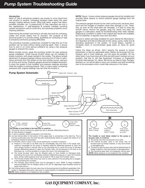
NOTE: Figure 1 shows where pressure gauges should be installed and<br />
provides blank spaces to record pressure gauge readings from the<br />
original tests.<br />
The pressure gauges should not be used continuously, because vibrations<br />
and the ravages of weather cause their damage or ruin. Therefore,<br />
as soon as the initial tests are complete, it is best to close the<br />
shutoff valves, remove the gauges, plug the valves and keep the<br />
gauges in a safe place, ready for troubleshooting when really needed.<br />
Diagnosing a problem is easier if the original test results are available,<br />
but not essential. It requires more time and effort.<br />
Be sure to obtain and keep available for quick referral the Manufacturer’s<br />
Operation and Service Manuals for the valves, pump, meter and all<br />
operating equipment in the system. To avoid delays, maintain a<br />
complete stock of recommended spare parts on hand for quick<br />
repairs.<br />
Follow the steps as shown. Don’t assume the answer is known<br />
beforehand, or skip any applicable steps. Rather, be thorough and methodical,<br />
and in most instances, you will solve the problem. On the<br />
other hand, if you have done all of this and still haven’t worked out your<br />
problem, feel free to call <strong>Gas</strong> <strong>Equipment</strong> <strong>Company</strong> or Engineered<br />
Controls International, <strong>Inc</strong>. direct. We will do our best to help. Perhaps,<br />
between us, we will be able to solve your problem and add something<br />
new to the procedure which could help everyone in the future.<br />
Pump System Schematic<br />
Supply tank pressure - psig<br />
P 1<br />
P 2<br />
P 3<br />
P 4<br />
Supply tank<br />
Meter pressure<br />
Pump inlet pressure - psig<br />
Bypass Valve<br />
Pump Outlet<br />
Pressure–PSIG<br />
Hose<br />
➝<br />
Tank pressure<br />
P 1 doesn’t change<br />
A<br />
Pump<br />
Meter Assembly<br />
Vapor Eliminator<br />
Meter Chamber<br />
Differential Valve<br />
The trouble is most likely in the inlet line. It could be:<br />
1. The pump may be running at a speed too low to develop differential pressure.<br />
2. An inlet strainer is clogged.<br />
3. A valve is partially closed somewhere in the inlet time.<br />
4. Ice has formed either in the bottom of the supply tank or somewhere in the inlet line. This is<br />
common particularly when the tank has been hydrostatically tested or purged with steam & not<br />
completely drained & dehydrated.<br />
5. If a Flomatic valve is used, it may not be opening for a number of reasons:<br />
a) Pressure in the tank to be filled may be considerably less than that in the supply tank,<br />
making it impossible for the pump to develop sufficient differential pressure to open the<br />
valve (simply throttle a manual valve on the discharge line to cause the pump to develop<br />
enough differential pressure to open the Flomatic valve. As the pressure in the tank to be<br />
filled goes up, it will be possible to re-open the valve in the discharge line.)<br />
b) The pump by-pass valve may be blocked open or have broken or damaged parts,<br />
preventing the pump from developing sufficient differential pressure to open the Flomatic<br />
valve. (Pump outlet pressure must rise at least 21 PSI to open the Flomatic valve.)<br />
c) The Flomatic strainer, filter, three-way valve or other element in the actuating line is clogged,<br />
or the activating line is kinked.<br />
d) The Flomatic valve internal parts may be damaged or worn. (Refer to Rego installation<br />
manual #A7884F-301 for flanged valves or #L-451 for diaphragm-type threaded valves for<br />
repair instructions.)<br />
6. If an internal valve is used, the main valve may not be opening due to insufficient equalization time,<br />
broken or damaged valve parts, valve lever in closed position or insufficient excess flow sizing.<br />
NOTE: Meter pressure is not needed for this condition.<br />
➝<br />
➝<br />
P 2<br />
Pump inlet<br />
pressure decreases<br />
P 1<br />
Pump outlet<br />
pressure<br />
doesn’t change<br />
➝<br />
P 1<br />
Tank pressure<br />
doesn’t change<br />
Tank To Be Filled<br />
➝<br />
B<br />
P 2<br />
Pump inlet<br />
pressure<br />
doesn’t change<br />
The trouble is most likely related to the pump or<br />
by-pass valve. It could be:<br />
1. The pump may have excessively worn parts.<br />
2. The internal by-pass valve in the pump may be<br />
blocked open by foreign material, or may have broken<br />
or damaged parts.<br />
3. The back-to-tank by-pass valve may be blocked open by<br />
foreign material or may have broken or damaged parts.<br />
4. The manual by-pass valve, if so equipped, may be open.<br />
NOTE: Meter pressure is not needed for this condition.<br />
P 3<br />
Pump outlet<br />
pressure goes<br />
up a little<br />
118