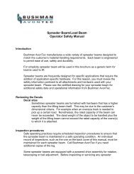
Load Inverter Service - Bushman Equipment, Inc.
Load Inverter Service - Bushman Equipment, Inc.
Load Inverter Service - Bushman Equipment, Inc.

You also want an ePaper? Increase the reach of your titles
YUMPU automatically turns print PDFs into web optimized ePapers that Google loves.
<strong>Load</strong> <strong>Inverter</strong> <strong>Service</strong> and Operating Manual<br />
Table of Contents<br />
Product Information ........................................................................................................... 2<br />
Introduction ....................................................................................................................... 3<br />
Safety Instructions ............................................................................................................ 4<br />
Responsibilities of Operator .............................................................................................. 5<br />
Removal from <strong>Service</strong> ........................................................................................... 5<br />
Repairs .................................................................................................................. 5<br />
Operators .............................................................................................................. 5<br />
Before Operation ................................................................................................... 5<br />
During Operation ................................................................................................... 5<br />
Modifications and Alterations ................................................................................ 5<br />
Description of <strong>Equipment</strong> .................................................................................................. 6<br />
Operation of <strong>Equipment</strong> .................................................................................................... 6<br />
Installation ......................................................................................................................... 7<br />
Voltage Requirements ........................................................................................... 7<br />
Remote Motor Starter ............................................................................................ 8<br />
Photo-eyes ............................................................................................................ 8<br />
Internal Motor Starter ............................................................................................ 8<br />
Reverse Phase Relay ........................................................................................... 8<br />
Operation .............................................................................................................. 8<br />
Using the <strong>Inverter</strong> .............................................................................................................. 9<br />
Operating Condition .............................................................................................. 9<br />
Chain Breakage .................................................................................................... 9<br />
Safe Operating Procedure .............................................................................................. 10<br />
Maintaining the <strong>Inverter</strong> .................................................................................................. 11<br />
Hydraulic Scissors Clamp ................................................................................... 11<br />
Daily Operator Checks ........................................................................................ 11<br />
Quarterly Maintenance ........................................................................................ 11<br />
Lubrication ........................................................................................................... 12<br />
Chain Tensioning & Replacement ....................................................................... 12<br />
Adjustment Procedure ......................................................................................... 12<br />
Chain Replacement ............................................................................................. 12<br />
Limit Switches ..................................................................................................... 13<br />
Warranty ......................................................................................................................... 14<br />
Page 1<br />
www.<strong>Bushman</strong>AvonTec.com * Sales@<strong>Bushman</strong>AvonTec.com
<strong>Load</strong> <strong>Inverter</strong> <strong>Service</strong> and Operating Manual<br />
Product Information<br />
This <strong>Service</strong> and Operating Manual applies to the following <strong>Bushman</strong> AvonTec machinery:<br />
Product Type:<br />
<strong>Load</strong> <strong>Inverter</strong><br />
Model Number:<br />
Rated <strong>Load</strong> Capacity:<br />
Serial #:<br />
Registered User:<br />
Date Shipped:<br />
For warranty information, service, and replacement parts information, please call your local<br />
dealer or <strong>Bushman</strong> AvonTec at (800) 558-7850. Please have the above information available<br />
when calling.<br />
This manual should be kept with the machine at all times. In the event the machine is re-sold,<br />
or transferred to another facility, please contact the factory so that we can update our service<br />
and warranty records.<br />
Page 2
<strong>Load</strong> <strong>Inverter</strong> <strong>Service</strong> and Operating Manual<br />
Introduction<br />
Congratulations on your purchase of <strong>Bushman</strong> AvonTec <strong>Load</strong> <strong>Inverter</strong>. When correctly<br />
installed, operated, and maintained the load inverter is a most reliable and efficient means of<br />
turning large and heavy loads. <strong>Load</strong> inverters have been successfully used to turn products<br />
ranging from sheet steel stacks to thermoformed panels for the construction industry.<br />
The <strong>Bushman</strong> AvonTec barrel-type load inverter is designed and built to provide many years of<br />
efficient service. Like any piece of industrial equipment, there are some important safety rules<br />
to follow when installing and operating this equipment.<br />
This manual provides instructions for correctly installing, using and maintaining this equipment.<br />
Due to the customized nature of the equipment, some information may not apply to your<br />
<strong>Inverter</strong>. If you are not the first owner of this equipment, you should consult the factory before<br />
operating to ensure that its specifications are appropriate for your application. Additionally,<br />
some service and safety information relating to specialized components such as conveyor<br />
drives, gear motors, electrical components, etc. may be contained in the instruction documents<br />
provided by their manufacturers. Refer to these documents before servicing or working with<br />
these components.<br />
Page 3
<strong>Load</strong> <strong>Inverter</strong> <strong>Service</strong> and Operating Manual<br />
Safety Instructions<br />
Safety Instructions for <strong>Load</strong> <strong>Inverter</strong>s:<br />
1. Do not operate this equipment unless you have been trained and authorized to<br />
do so.<br />
2. Before using inverter, inspect it for proper operation and condition.<br />
3. Before using inverter, inspect all safety devices (such as bogey wheel guards)<br />
to be certain they are in place and functioning properly.<br />
4. Do not exceed the inverter's capacity as stated on the serial number plate.<br />
5. Center loads on the load/unload platforms. Make sure that the load to be<br />
inverted is appropriately sized and shaped. All pallets or skids used should be<br />
flat and in good condition, with no broken boards. The top of the load should be<br />
parallel to the base.<br />
6. Keep the entire load within the perimeter of the platform while the inverter is in<br />
motion.<br />
7. Ensure that people and objects are clear of the areas beneath the platform and<br />
immediately surrounding the perimeter of the inverter while it is in motion.<br />
8. DANGER! Do not work under inverter without the maintenance device(s) in<br />
position or the machine safely blocked and secure. See the maintenance section<br />
of this manual to learn about safe use of the maintenance device and how to<br />
block machine safely.<br />
Page 4
<strong>Load</strong> <strong>Inverter</strong> <strong>Service</strong> and Operating Manual<br />
Responsibilities of Operator<br />
Inspection and Maintenance<br />
The machine shall be inspected and maintained in proper<br />
working order in accordance with the manufacturer's operating/maintenance instructions and<br />
safe operating practices.<br />
Removal from <strong>Service</strong><br />
Any machine not in safe operating condition shall be removed from<br />
service until it is repaired to the original manufacturer's specifications.<br />
Repairs<br />
All repairs shall be made by authorized personnel in conformance to<br />
the manufacturer’s instructions.<br />
Operators<br />
Only trained and authorized personnel shall be permitted to operate the machine.<br />
1. Before using the machine, the operator shall have:<br />
A. Read and/or have explained and understood the manufacturer's<br />
operating instructions and safety rules, or have been trained by a<br />
qualified person.<br />
B. Inspected the machine for proper operation and condition. Any<br />
suspect item shall be carefully examined and a determination<br />
made by a qualified person as to whether it constitutes a safety<br />
hazard. All unsafe items shall be corrected before further use of<br />
the machine.<br />
2. During operation the machine shall be used only in accordance with its intended<br />
use and within the manufacturer's limitations and safety rules.<br />
A. Do not overload the machine.<br />
B. Ensure that all safety devices are operational and in place.<br />
Modifications and Alterations<br />
Modifications or alterations of machinery shall only be made with the written permission of the<br />
original manufacturer. These changes shall be in conformance with all applicable standards<br />
and shall render the equipment as safe as it was before modification. These changes shall also<br />
satisfy all safety recommendations of the original equipment manufacturer for the particular<br />
application of the machine.<br />
Page 5
<strong>Load</strong> <strong>Inverter</strong> <strong>Service</strong> and Operating Manual<br />
Description of <strong>Equipment</strong><br />
The barrel-type load inverter consists of a series of rings, formed from rolled steel channel.<br />
These rings are connected by longitudinal members to form a cylindrical shaped “barrel” cradle.<br />
The cradle rests on four bogey wheels, one at each corner of the machine. The bogey wheels<br />
are attached to a base plate or frame that rests on the floor.<br />
Attached to one or more of the rolled steel rings will be a heavy-duty riveted roller chain. This<br />
chain is driven via a gearbox by an electric motor. At each end of rotation, electrical limit<br />
switches or other sensors halt rotation of the barrel.<br />
Located on one platform within the barrel cradle, is a hydraulic scissors clamp. This scissors<br />
clamp uses double-acting hydraulic cylinders to raise and lower the platform. The scissors<br />
clamp uses a hydraulic pressure switch to sense when a load has been successfully clamped.<br />
See section on “Hydraulic Scissors Clamp” in this manual for information on servicing and<br />
operating the scissors clamp.<br />
Operation of <strong>Equipment</strong><br />
<strong>Load</strong> inverters are used to invert or “turn over” large and heavy loads of materials. The scissors<br />
clamp and pressure switch allows a wide range of sizes and weights of loads to be inverted<br />
using this equipment, however some loads may require special handling or preparation before<br />
inverting.<br />
Normal operation consists of placing the load to be inverted into the machine. This is done<br />
either by using a forklift or other material handling trucks. If equipped with powered roller<br />
conveyors, loads may be conveyed into the machine. Care should be taken that no load or<br />
portion of the load extends outside of the machine. Severe personal injury or damage to the<br />
equipment may result if the machine is operated with part of a load extending outside of the<br />
machine.<br />
When the load is positioned inside the machine, the “clamp” portion of the cycle is started.<br />
Hydraulic fluid is pumped from the reservoir into the double-acting hydraulic cylinders in the<br />
scissors clamp. The clamp platform descends until it contacts the top of the load. This<br />
increases the hydraulic system pressure until the appropriate clamp pressure is attained. Once<br />
clamp pressure is attained, the inversion cycle begins.<br />
During the inversion cycle, the gear motor drives the inversion cradle in a circle, until the<br />
electrical limit switches are tripped. At this point, the load is fully inverted. The scissors clamp<br />
will then automatically retract. <strong>Load</strong>s may then be removed from the machine, either using a<br />
forklift, or (if supplied) using the powered conveyor.<br />
Page 6
<strong>Load</strong> <strong>Inverter</strong> <strong>Service</strong> and Operating Manual<br />
Installation<br />
<strong>Bushman</strong> AvonTec inverters are shipped completely assembled and ready to install. If the unit<br />
is to be pit-mounted, an appropriate size pit should be prepared before moving the unit into<br />
position. (Contact factory for instructions regarding pit size, etc.)<br />
Careful consideration should be given to placement of the inverter within the plant. It should be<br />
placed on a level, dry floor, of suitable strength to bear the weight of the equipment and its load.<br />
There should be sufficient space to allow the unit to be loaded and unloaded using overhead<br />
hoists and or forklift-type material handling trucks. Consideration should also be given to the<br />
placement of the power supply cable and control box cord. Severe personal injury and or death<br />
can result if electrical cables are cut accidentally. Sufficient overhead clearance should be<br />
provided so that the largest potential load can rotate freely.<br />
<strong>Inverter</strong>s are supplied with lag-down holes in the base plate. It is recommended that all<br />
inverters be bolted to the floor using appropriately sized bolts. Failure to bolt unit down can<br />
result in severe injury to persons using the equipment, and possible damage to equipment or<br />
materials.<br />
The machine may be transported through the plant by one of three methods:<br />
1. Lift eyes are provided at each corner of the inverter. An appropriately<br />
rated chain may be attached to each lift eye, and the unit may be moved<br />
via overhead cranes or hoists. Refer to manufacturer’s plate on base of<br />
inverter for weight information.<br />
2. Chains attached to the lift-eyes may be lifted by a forklift-type truck.<br />
Check that the weight of the equipment does not exceed forklift capacity.<br />
3. The unit is shipped from the factory with wooden blocks at each corner<br />
underneath the base plate. Forklift forks may be inserted between these<br />
blocks. Take care to only lift the unit from the side, and to make sure that<br />
the forks extend sufficiently to lift the unit safely. Blocks may be removed<br />
once the machine is in place by lifting each corner of the inverter in turn<br />
with a forklift or hoist, unbolting and removing the block, and then<br />
lowering each corner.<br />
Voltage Requirements<br />
The inverter is designed to operate on a variety of power supply voltages. The <strong>Bushman</strong><br />
AvonTec inverter uses a multi-voltage motor; however, it is shipped with overload protection<br />
heaters appropriate to the operator requirements as specified to the factory at the time of order.<br />
If the unit is connected to a power supply with a voltage different from what it was originally<br />
specified to the factory, replacement overloads should be installed before operation. Failure to<br />
install correct overloads will result in inverter failure, and can result in damage to the equipment<br />
and possible serious or fatal personal injury.<br />
Page 7
<strong>Load</strong> <strong>Inverter</strong> <strong>Service</strong> and Operating Manual<br />
Remote Motor Starter<br />
If the starter is mounted externally, it will be necessary to supply 3-phase power of the<br />
appropriate voltage to the starter, and then wire the starter to the motor in the base frame. In<br />
most cases, the motor leads will terminate in an outlet box in the base frame and the leads from<br />
the starter can be wired to this outlet box. A control circuit transformer is provided with the<br />
magnetic starter and additional wires will be required from the transformer to an outlet box in the<br />
base frame. These will pick up the limit switch and the push button that can be attached to this<br />
outlet box.<br />
Photo-eyes<br />
If the inverter is equipped with external photo-eyes, they should be positioned at the ends of the<br />
machine to detect the presence of a load. They will be wired to the junction box attached to the<br />
PLC. Each lead from the photo-eye assembly will be labeled. Attach each numbered wire to<br />
the matching terminal in the junction box.<br />
The photo-eyes may need to be adjusted depending on the “reflectivity” of the load. Highly<br />
reflective loads may trigger a false reading, and may not stop the conveyor drive properly.<br />
Refer to the technical documentation that is supplied with the photo-eyes for more information.<br />
Internal Motor Starter<br />
If the starter is mounted internally, it is necessary to knock out a hole in the enclosure box inside<br />
the base frame of the unit. If your inverter was ordered with J.I.C. standard enclosures, you will<br />
have to drill a hole through the enclosure and fit a gasket around the wire). A power cord<br />
should then be inserted through this hole. Attach each wire to one terminal on the motor starter,<br />
labeled L1, L2, and L3.<br />
Reverse Phase Relay<br />
<strong>Bushman</strong> AvonTec inverters are equipped with a reverse phase relay that prevents accidental<br />
incorrect rotation of the unit if it is wired out of phase. Should the unit fail to operate when<br />
power is supplied, and the push buttons are depressed, it will be necessary to reverse any two<br />
of these line wires. Do not attempt to adjust or work on the reverse phase relay. Most inverters<br />
are shipped with a Reverse Phase Relay that has a red L.E.D. indicator light. This indicator<br />
light will illuminate when power has been correctly installed, and the unit is wired in phase.<br />
Operation<br />
After the starter and operating switches have been connected as above, and are in accordance<br />
with the attached wiring diagrams, the inverter is ready to operate. <strong>Bushman</strong> AvonTec<br />
recommends that before production use, a full range of load sizes and configurations be tested<br />
in the machine to ensure that clamp pressures and other settings are correct. During testing, it<br />
is recommended that personnel stand clear from the machine, and that an operator observes<br />
the machine. Use the “E-Stop” button to halt operation of the machine, if any unexpected<br />
condition occurs during testing.<br />
Page 8
<strong>Load</strong> <strong>Inverter</strong> <strong>Service</strong> and Operating Manual<br />
Using the <strong>Inverter</strong><br />
WARNING! Do not place loads on the inverter that overhang either platform or exceed<br />
the rated load capacity of the machine. Doing so places extreme stress on<br />
the motor, gearbox, and chain, and can cause breakage of these components and severe<br />
personal injury or death.<br />
Once the load to be inverted is in place, you may begin the inversion cycle. The operator<br />
should ensure that the area around and underneath the machine is free from obstructions, and<br />
that persons in the area stand clear. The operator should then depress the appropriate<br />
pushbutton to begin inversion.<br />
Operating Condition<br />
The inverter should rotate smoothly, and without any scraping or banging noises. If any of<br />
these conditions are noted, the operator should immediately discontinue use of the equipment<br />
until it has been checked by qualified maintenance personnel. Jerking motion or scraping and<br />
banging noises are indications that the unit is not operating correctly and requires maintenance.<br />
Never place any part of the body inside the <strong>Inverter</strong> while it is operating, or without blocking and<br />
securing the inversion cradle.<br />
Chain Breakage<br />
Should the chain break during operation, do not attempt to service the machine until the load<br />
has been removed and the platform returned to the "balanced" 45-degree position, and the<br />
maintenance pin inserted. Chain breakage is usually an indication that the platforms are not<br />
rotating freely because of damage to the frame or because of loading more than the stated<br />
capacity. Do not replace chains until the cause of the breakage has been determined and<br />
corrected. If the breakage is found to be a result of overloading, contact the factory regarding<br />
possible upgrading of your existing inverter.<br />
In situations where you wish to invert a load that is not unitized (e.g. a pallet load of multiple<br />
cartons, etc.) make sure that the load is secured and banded before upending. Do not place<br />
any straps or chains across the rolling surfaces of the upending platform.<br />
Page 9
<strong>Load</strong> <strong>Inverter</strong> <strong>Service</strong> and Operating Manual<br />
Safe Operating Procedure<br />
Ensure that all operators and maintenance personnel working with the equipment have read<br />
and/or had explained, and understand these safety instructions before operating or performing<br />
work on the equipment. Failure to heed these instructions can possibly lead to severe personal<br />
injury.<br />
1. Keep clear of the machinery at all times, and particularly when it is operating.<br />
2. Do not climb or ride on the machine.<br />
3. Ensure that all safety guards and limit switches are in place and are in working<br />
order.<br />
4. Do not enter area under the machine unless the machine has been electrically<br />
locked and tagged out, and the moving cradle has been placed and blocked in<br />
the "balanced" position.<br />
5. Never remove the chain(s) or any other component of the drive system without<br />
first ensuring that the moving cradle is in the "balanced" position and blocking it<br />
in this position. The cradle is held in the vertical and horizontal position by the<br />
chain(s) and the drive system and is unbalanced. When the chain(s) or drive<br />
system is loosened, the cradle will move rapidly to the "balanced" position, and<br />
could cause serious injury to any person close to it.<br />
6. Should it be necessary, for operational reasons, to be on one of the cradle<br />
platform surfaces, always use the correct ladders, safety harnesses, and other<br />
safety equipment necessary to protect persons from falling from unprotected<br />
heights.<br />
7. Do not bump the cradle with the product being rotated or with cranes, crane<br />
hooks, or lift trucks. Shock loads may cause failure of the chain(s) or other drive<br />
system components and could cause unexpected movement of the cradle and<br />
injury to persons.<br />
8. Never try to lubricate moving machinery. Ensure lockout and tag-out<br />
procedures are used before all lubrication and maintenance.<br />
9. Keep rotator chain(s) correctly adjusted to prevent excess wear and stress on the<br />
drive system. See sections on chain adjustment for instructions on adjusting<br />
chain(s).<br />
10. Use extreme caution at all times when loading and unloading the machine to<br />
ensure that the load is always in a secure mode.<br />
11. Do not overload the machine. See the rated capacity on the serial plate.<br />
12. Do not rotate loads that project over front edge of the cradle platform. Ensure all<br />
loads are centrally placed and even from side to side.<br />
Page 10
<strong>Load</strong> <strong>Inverter</strong> <strong>Service</strong> and Operating Manual<br />
Page 11
<strong>Load</strong> <strong>Inverter</strong> <strong>Service</strong> and Operating Manual<br />
Maintaining the <strong>Inverter</strong><br />
A qualified person who understands all safety and operating instructions should perform all<br />
maintenance.<br />
Hydraulic Scissors Clamp<br />
Refer to the appropriate manual sections for information relating to the hydraulic scissors<br />
platform.<br />
Daily Operator Checks<br />
Inspect the machine to ensure that all guards and limit switches are in place.<br />
Check to see that the cradle is square and that both platforms are square and parallel to the<br />
floor. If this is not the case, the cradle may have come off its supporting bogey wheels, or a<br />
bogey wheel bearing may have failed. If this is the case, DO NOT operate machine, and<br />
request maintenance assistance.<br />
Before loading the machine, operate the unit unloaded through one complete cycle. Observe<br />
rotation and smoothness of operation. Report any unusual observations and/or noises, and DO<br />
NOT operate machine until it has been checked and repaired.<br />
Check control power cord for wear.<br />
During normal operation of the machine, report any unusual observations and/or noises that<br />
may suddenly occur. DO NOT use the machine until a qualified person has checked it.<br />
Quarterly Maintenance<br />
Qualified maintenance personnel should perform the following at least quarterly:<br />
1. Check chains and drive components (sprockets, bushings, etc.) for wear<br />
and correct adjustment. See instructions for adjusting chains.<br />
2. Check oil level in gear reducer. If necessary, bring oil to correct operating<br />
level. See section in manual covering gearbox.<br />
3. Flush all bearings with grease. "Zerk" type fittings are found at all bearing<br />
locations, and are fitted with a red plastic removable cap. See attached<br />
diagram for grease point locations. Use high quality 120# multi-purpose<br />
grease.<br />
4. Check bogey wheels for wear.<br />
5. Adjust spring-load motor brake if necessary. See details in section on brakes.<br />
6. Check electrical cords and components for wear.<br />
Page 12
<strong>Load</strong> <strong>Inverter</strong> <strong>Service</strong> and Operating Manual<br />
Lubrication<br />
Flush all bearings with grease four times a year. <strong>Bushman</strong> AvonTec recommends using a good<br />
grade of 120# multi-purpose grease. Zerk fittings will be found at all bearing locations.<br />
Bearings are found in all members which rotate during operation around a fixed shaft or in the<br />
rollers which support the rotating cradle assembly. At the same time, the oil level in the gearbox<br />
should be checked. Please consult the lubrication and maintenance information for the gear<br />
motor that is included at the end of this manual.<br />
Chain Tensioning and Replacement<br />
<strong>Inverter</strong>s are driven by a powered sprocket turning a chain that is fixed to either a circular plate<br />
or a rolled steel channel that is part of the inverting cradle. It is necessary to maintain adequate<br />
tension in this chain and not to allow it to become slack. Slackness in the chain will result in<br />
excess wear and shock loads on the drive system.<br />
The chain is correctly adjusted when it is held snugly against its circular backing plate or rolled<br />
steel channel. If the chain can be pulled away from the backing plate, then it is too loose and<br />
requires adjustment.<br />
Adjustment Procedure<br />
Remove all loads from the inverter. Use the manual control buttons located inside the electrical<br />
panel to rotate the machine to the “start” position, with the scissors clamp at the bottom of the<br />
inverter. When the platforms are in this position, use chains or other devices to “lock” the<br />
rotating inverter cradle in position. This will prevent accidental movement of the platform.<br />
Disconnect power to the inverter using the correct lockout procedures<br />
Check anchor bolt adjustment range at the end of the chain. All bolts should have<br />
approximately the same amount of thread showing through the anchor nut. If this is not the<br />
case, loosen one end and tighten the other until the thread showing is approximately equal.<br />
Tighten both anchor bolts equally until the chain is just snug against the backing plate. There<br />
should be no droop in the chain, and it should not come away from the backing plate when<br />
pulled at 90 degrees to the plate. The chain should still have some flex in it if not it is<br />
over-tensioned.<br />
For units with two chains, it is necessary to ensure that each chain has a similar tension. Use a<br />
torque wrench to match the tension on each chain.<br />
Remove the maintenance locking pin (if supplied) and then restore power and observe<br />
operation of the unit. On two-chain units, the cradle should rotate evenly on the bogey wheels<br />
without a tendency to move in one or the other direction. Should this happen, then one chain is<br />
tighter than the other is. If this happens, repeat until unit tracks evenly.<br />
Chain Replacement<br />
Should it ever be necessary to replace chain, due to either wear or breakage, and then follow<br />
the procedures above, ensuring that the chain anchor bolts are correctly adjusted when the new<br />
chain is installed.<br />
Page 13
<strong>Load</strong> <strong>Inverter</strong> <strong>Service</strong> and Operating Manual<br />
Limit Switches<br />
<strong>Bushman</strong> AvonTec inverters are equipped with four limit switches; two switches are located at<br />
each end of the 180° of travel. The inside limit switch of each pair is the normal stopping limit<br />
switch that stops the platform in a level position. If the platform should begin to stop slightly<br />
short of 180° or slightly beyond 180°, the limit switch should be re-adjusted by changing the<br />
position of the operating arc of the limit switch. If this does not correct the situation, there is also<br />
a certain amount of adjustability in the cam that trips the limit switch. The outside limit switch at<br />
each end of 90 degree travel is a safety or over travel limit switch. These switches will only<br />
operate if the first stop switch becomes inoperative or is damaged. If the inverter stops at the<br />
overtravel limit switch, the inside limit switch should be replaced. Contact the factory for<br />
replacement limit switch information. Do not operate the inverter until both inside limit switches<br />
are operating correctly.<br />
Statement of Warranty<br />
The <strong>Bushman</strong> AvonTec will replace, F.O.B. the factory, any goods that are defective in<br />
materials and workmanship within 12 months of date of shipment, provided the buyer returns<br />
the defective materials, freight and delivery prepaid, to the manufacturer, which shall be the<br />
buyer’s sole remedy for defective materials.<br />
Manufacturer shall not be liable to purchaser or any other person or entity for consequential or<br />
incidental damages. The end user is responsible for the integrity of any structure, crane or<br />
fixture to which <strong>Bushman</strong> products have been attached. This warranty does not apply to<br />
equipment and/or components, which have been altered in any way or subjected to abusive or<br />
abnormal use, inadequate maintenance or lubrication, or use beyond seller recommended<br />
capacities and specifications.<br />
Manufacturer shall not be liable under any circumstances, for labor costs expended on such<br />
goods or consequential damages. Manufacturer shall not be liable to purchaser or any other<br />
person or entity for loss or damage directly or indirectly arising from the use of goods or from<br />
any other cause.<br />
No employee, agent, officer or seller is authorized to make further oral or written representations<br />
or warranty of fitness or to waive any of the foregoing terms of sale, and none shall be binding<br />
on the manufacturer.<br />
If there are any problems or questions regarding this equipment or its application, contact your<br />
local sales representative or <strong>Bushman</strong> AvonTec directly at 262 790-4207 or 800-338-7810.<br />
Page 14