


White Piston Pump Closed Circuit.pdf
White Piston Pump Closed Circuit.pdf
White Piston Pump Closed Circuit.pdf

Create successful ePaper yourself
Turn your PDF publications into a flip-book with our unique Google optimized e-Paper software.
KP<br />
3<br />
FEATURES<br />
4<br />
1<br />
1<br />
2<br />
Cylindrical Roller Bearing supports the<br />
thrust load generated by the piston group.<br />
Bronze-Coated Wear Plate dissipates<br />
heat and transfers it to the case drain oil.<br />
3<br />
High Volume Charge <strong>Pump</strong> creates<br />
additional flow through the case drain,<br />
flushing hot oil from the pump.<br />
4<br />
By-Pass Valve enables free-wheeling<br />
when a non-operable machine needs to<br />
be moved.<br />
5<br />
Cooling Fins help dissipate heat into the<br />
atmosphere.<br />
5<br />
2<br />
The KP Series of pump is the newest addition to our<br />
rapidly expanding product line. The product is a<br />
variable displacement, axial piston pump and is a<br />
natural compliment to the drive products historically<br />
offered by <strong>White</strong> Hydraulics. This product is ideally<br />
suited for the lawn and garden, and under 50 hp<br />
construction markets. Features and capabilities<br />
include minimum and maximum continuous speeds of<br />
600 rpm and 3,600 rpm, respectively, industry<br />
standardized mounting flanges, pressure ratings that<br />
are comparable to competitive product offerings and<br />
the option of incorporating <strong>White</strong> Hydraulics’ Shock<br />
Reduction Technology (SRT).<br />
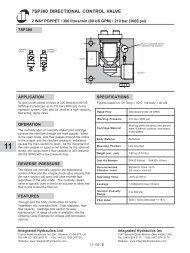
SPECIFICATIONS<br />
Displacement<br />
in 3 /rev. (cc/rev.)<br />
Weight<br />
lb (kg)<br />
Max. Pressure psi (bar)-<br />
1)Cont. 2)Inter. 3)Peak<br />
Code<br />
Max. Speed (rpm) -<br />
1)Min 2)Max<br />
Charge <strong>Pump</strong><br />
in 3 /rev. (cc/rev.)<br />
010<br />
013<br />
018<br />
.62 (10)<br />
.79 (13)<br />
1.10 (18)<br />
1 2<br />
600 3600<br />
600 3600<br />
600 3600<br />
7.9 (3.6)<br />
7.9 (3.6)<br />
15.0 (6.8)<br />
.18 (3)<br />
.18 (3)<br />
.18 (3)<br />
1 2 3<br />
1425 (98) 2125 (147) 3500 (241)<br />
1425 (98) 2125 (147) 3500 (241)<br />
1425 (98) 2125 (147) 3500 (241)<br />
2
Oil Temperature-<br />
Viscosity Rating-<br />
Filter-<br />
Return to Neutral-<br />
KP<br />
OPERATING PARAMETERS<br />
Although the pumps use cooling fins to help dissipate heat, we recommend that the continuous<br />
system temperature be kept at or below 195°F (90°C). It can see an intermittent temperature of<br />
212°F (100°C) and a peak temperature of 230°F (110°C).<br />
We recommend use of a 60 SUS (10cSt) viscosity hydraulic oil at no more than 212°F (100°C).<br />
Due to the precise machining and exact tolerances in the pump, <strong>White</strong> Hydraulics recommends<br />
a filter rating of 20 Micron absolute.<br />
See figure below. (All dimensional information contained in this catalog are inch units.)<br />
2.13<br />
2.13<br />
20° 20°<br />
1.69<br />
20° 20°<br />
1.69<br />
(2) Ø .33 (2) Ø .33<br />
1.69 1.69<br />
Shock Reduction -<br />
Technology (SRT)<br />
Ordering Information-<br />
Input Shaft Direction-<br />
<strong>White</strong> Hydraulics has developed the SRT for motors used in conjunction with the KP <strong>Pump</strong>s.<br />
This technology reduces the effect of pressure spikes and resulting shock loads to the hydraulic<br />
drive system.<br />
The KP needs to be application specific. Please contact <strong>White</strong> Hydraulics for ordering<br />
information.<br />
KP pumps can be configured with the input shaft to be powered in a clockwise or<br />
counterclockwise direction. The standard is counterclockwise. Input shaft rotation must be<br />
specified at time of order. Please consult <strong>White</strong> Hydraulics.<br />
3
101<br />
10cc & 13cc RIGHT HAND PUMP<br />
INPUT SHAFT ROTATION<br />
5.12<br />
2.09 2.09<br />
Counterclockwise Clockwise<br />
5.79<br />
2.40<br />
Flow<br />
Direction<br />
DDC* A B A B<br />
Port a Out In In Out<br />
Port b In Out Out In<br />
2.81<br />
.44<br />
.57<br />
* Direct Displacement Control<br />
.33<br />
Ø .47<br />
Ø .20<br />
Case Drain<br />
Location #3<br />
DDC<br />
20° 20°<br />
A<br />
B<br />
2.47<br />
5.47<br />
Case Drain<br />
Location #2<br />
Suction Port<br />
Location #2<br />
Suction Port<br />
Location #1<br />
Ø 3.25<br />
.30<br />
6.21 2.13<br />
Case Drain<br />
Location #1<br />
Suction Ports and Drain Ports<br />
are 9/16” -18 UNF SAE O-Ring<br />
4.13<br />
.39<br />
Left and Right Hand <strong>Pump</strong>s are determined by the<br />
location of the DDC when looking at the side of the<br />
pump with Ports a and b while the input shaft is<br />
facing down.<br />
8.21<br />
Port b<br />
3/4”-16 UNF-2B<br />
SAE O-Ring Boss<br />
.83<br />
.83<br />
Port a<br />
3/4”-16 UNF-2B<br />
SAE O-Ring Boss<br />
4
101<br />
10cc & 13cc LEFT HAND PUMP<br />
5.12<br />
2.09 2.09<br />
2.40<br />
5.79<br />
10 & 13cc SHAFT DETAIL<br />
2.00<br />
Mounting<br />
Flange<br />
1.18<br />
.20<br />
.44<br />
.31<br />
.57<br />
2.81<br />
.47<br />
.59<br />
Ø .20<br />
Ø .47<br />
.33<br />
M6 x .59 Deep<br />
20° 20°<br />
B<br />
A<br />
Case Drain<br />
Location #3<br />
DDC<br />
2.47<br />
5.47<br />
Case Drain<br />
Location #2<br />
Suction Port<br />
Location #2<br />
Suction Port<br />
Location #1<br />
Ø 3.25<br />
.30<br />
Suction Ports and Drain Ports<br />
are 9/16” -18 UNF SAE O-Ring<br />
Case Drain<br />
Location #1<br />
2.13<br />
6.21<br />
Left and Right Hand <strong>Pump</strong>s are determined by the<br />
location of the DDC when looking at the side of the<br />
pump with Ports a and b while the input shaft is<br />
facing down.<br />
.39<br />
4.13<br />
Port a<br />
3/4”-16 UNF-2B<br />
SAE O-Ring Boss<br />
Port b<br />
3/4”-16 UNF-2B<br />
SAE O-Ring Boss<br />
8.21<br />
5
101<br />
18cc RIGHT HAND PUMP<br />
INPUT SHAFT ROTATION<br />
5.50<br />
5.12<br />
2.09 2.09<br />
Flow<br />
Direction<br />
Counterclockwise Clockwise<br />
DDC* A B A B<br />
Port a Out In In Out<br />
Port b In Out Out In<br />
2.91<br />
.44<br />
3.52<br />
4.33<br />
* Direct Displacement Control<br />
.57<br />
.35<br />
Ø .59<br />
Ø .24<br />
Ø 3.25<br />
22° 22°<br />
A<br />
B<br />
7.21<br />
3.12<br />
5.78<br />
DDC<br />
Case Drain<br />
Location #2<br />
Case Drain<br />
Location #3<br />
(2) M8x1.25<br />
.63 Deep<br />
Suction Port<br />
1.38 Location #1 .20<br />
2.91<br />
Suction Port<br />
Location #2<br />
.69 .69<br />
1.38 1.38<br />
5.78<br />
Suction Ports and Drain Ports<br />
are 9/16” -18 UNF SAE O-Ring<br />
.47<br />
Case Drain<br />
Location #1<br />
7.95<br />
Left and Right Hand <strong>Pump</strong>s are determined by the<br />
location of the DDC when looking at the side of the<br />
pump with Ports a and b while the input shaft is<br />
facing down.<br />
Outlet Port b<br />
3/4”-16 UNF-2B<br />
SAE O-Ring Boss<br />
.93 .93<br />
Port a<br />
3/4”-16 UNF-2B<br />
SAE O-Ring Boss<br />
6
5.50<br />
5.12<br />
2.09 2.09<br />
2.91<br />
101<br />
18cc LEFT HAND PUMP<br />
18cc SHAFT DETAIL<br />
2.17<br />
Mounting<br />
Flange<br />
.44<br />
.20<br />
1.42<br />
.12<br />
3.52<br />
4.33<br />
.55<br />
.67<br />
M6 x .59 Deep<br />
Ø .24<br />
Ø .59<br />
.35<br />
.57<br />
Ø 3.25<br />
22° 22°<br />
B<br />
A<br />
DDC<br />
3.12<br />
7.21<br />
5.78<br />
(2) M8x1.25<br />
.63 Deep<br />
Case Drain<br />
Location #3<br />
Case Drain<br />
Location #2<br />
Suction Port<br />
Location #2<br />
.69 .69<br />
1.38 1.38<br />
2.91<br />
.20<br />
Suction Port<br />
Location #1<br />
.69<br />
1.38<br />
.69<br />
Suction Ports and Drain Ports<br />
are 9/16” -18 UNF SAE O-Ring<br />
5.78<br />
Left and Right Hand <strong>Pump</strong>s are determined by the<br />
location of the DDC when looking at the side of the<br />
pump with Ports a and b while the input shaft is<br />
facing down.<br />
7.95<br />
.47<br />
Case Drain<br />
Location #1<br />
Port a<br />
3/4”-16 UNF-2B<br />
SAE O-Ring Boss<br />
.93 .93<br />
Port b<br />
3/4”-16 UNF-2B<br />
SAE O-Ring Boss<br />
7
![Download Info Sheet [14MB .pdf] - Federal Fluid Power](https://img.yumpu.com/50820508/1/190x245/download-info-sheet-14mb-pdf-federal-fluid-power.jpg?quality=85)
![Download .pdf [3.91MB] - Federal Fluid Power](https://img.yumpu.com/48748421/1/190x245/download-pdf-391mb-federal-fluid-power.jpg?quality=85)
![Download Info Sheet [4.46MB .pdf] - Federal Fluid Power, Inc.](https://img.yumpu.com/47536262/1/190x245/download-info-sheet-446mb-pdf-federal-fluid-power-inc.jpg?quality=85)
![Download Info Sheet [2MB .pdf]](https://img.yumpu.com/41465608/1/184x260/download-info-sheet-2mb-pdf.jpg?quality=85)
![Download .pdf [7.32MB] - Federal Fluid Power, Inc.](https://img.yumpu.com/39318737/1/190x245/download-pdf-732mb-federal-fluid-power-inc.jpg?quality=85)

![Download Info Sheet [430KB .pdf] - Federal Fluid Power, Inc.](https://img.yumpu.com/39314496/1/190x245/download-info-sheet-430kb-pdf-federal-fluid-power-inc.jpg?quality=85)