model 2704 controller installation and operation handbook - Soliton
model 2704 controller installation and operation handbook - Soliton
model 2704 controller installation and operation handbook - Soliton

You also want an ePaper? Increase the reach of your titles
YUMPU automatically turns print PDFs into web optimized ePapers that Google loves.
<strong>2704</strong> Controller Contents<br />
MODEL <strong>2704</strong> CONTROLLER<br />
INSTALLATION AND OPERATION HANDBOOK<br />
1. CHAPTER 1 INTRODUCTION .................................................................................. 1.2<br />
1.1. ABOUT THIS MANUAL....................................................................................... 1.2<br />
1.1.1. The Structure Of This Manual............................................................................... 1.2<br />
1.2. WHAT IS <strong>2704</strong>........................................................................................................ 1.3<br />
1.3. BEFORE YOU BEGIN .......................................................................................... 1.4<br />
1.3.1. Unpacking.............................................................................................................. 1 .4<br />
1.3.2. Contents of Packaging ........................................................................................... 1.4<br />
1.3.3. Does the Controller Match the Process?................................................................ 1.4<br />
1.4. OPERATOR INTERFACE - OVERVIEW.......................................................... 1.6<br />
1.4.1. Status Messages..................................................................................................... 1.7<br />
1.5. INSTALLATION - OVERVIEW .......................................................................... 1.8<br />
1.6. I/O MODULES ....................................................................................................... 1.9<br />
2. CHAPTER 2 INSTALLATION.................................................................................... 2.2<br />
2.1. MECHANICAL INSTALLATION....................................................................... 2.2<br />
2.1.1. Positioning............................................................................................................. 2.2<br />
2.1.2. Outline dimensions Model <strong>2704</strong>............................................................................ 2.2<br />
2.1.3. Mounting the Controller........................................................................................ 2.3<br />
2.1.4. Unplugging <strong>and</strong> Plugging in the Controller........................................................... 2.3<br />
2.2. WIRING .................................................................................................................. 2.4<br />
2.2.1. Electrical Connections........................................................................................... 2.4<br />
2.2.2. Rear Terminal Layout............................................................................................ 2.4<br />
2.3. STANDARD CONNECTIONS.............................................................................. 2.6<br />
2.3.1. Power Supply Wiring (Line voltage)..................................................................... 2.6<br />
2.3.2. Relay Output.......................................................................................................... 2.6<br />
2.3.3. Sensor Input Connections...................................................................................... 2.7<br />
2.3.4. Analogue Input Connections ................................................................................. 2.8<br />
2.3.5. I/O Exp<strong>and</strong>er (or Additional Digital Input) ........................................................... 2.9<br />
2.3.6. Digital I/O............................................................................................................ 2.10<br />
2.4. OPTIONAL PLUG IN MODULE CONNECTIONS ........................................ 2.11<br />
2.4.1. Digital Communications Connections ................................................................. 2.11<br />
Installation <strong>and</strong> Operation H<strong>and</strong>book. Part No HA026502 Issue 1.0 Apr-00 a-1
Contents<br />
<strong>2704</strong> Controller<br />
2.4.2. I/O Modules......................................................................................................... 2.13<br />
2.5. TO CONNECT ZIRCONIA (DUAL SIGNAL) PROBE................................... 2.18<br />
2.5.1. Zirconia Probe Screening .................................................................................... 2.19<br />
3. CHAPTER 3 GETTING STARTED............................................................................. 3.2<br />
3.1. POWER UP............................................................................................................. 3.3<br />
3.1.1. The HOME Page ................................................................................................... 3.3<br />
3.2. THE OPERATOR BUTTONS .............................................................................. 3.4<br />
3.3. THE PROG BUTTON............................................................................................ 3.5<br />
3.4. THE LOOP SELECT BUTTON ........................................................................... 3.5<br />
3.5. THE AUTO MANUAL BUTTON......................................................................... 3.6<br />
3.5.1. To Change Setpoint (when the loop is in Auto) .................................................... 3.7<br />
3.5.2. To Change Output Power (when the loop is in Manual) ....................................... 3.7<br />
3.6. PARAMETERS AND HOW TO ACCESS THEM ............................................. 3.8<br />
3.6.1. Pages...................................................................................................................... 3.8<br />
3.7. NAVIGATION OVERVIEW................................................................................. 3.9<br />
3.7.1. To Select a Page Header ........................................................................................ 3.9<br />
3.7.2. To Navigate to a Parameter from a Page Header. ................................................ 3.10<br />
3.7.3. To Change Next Parameter in the List................................................................. 3.11<br />
3.7.4. To Change Any Parameter in the List.................................................................. 3.11<br />
3.8. BACKSCROLL .................................................................................................... 3.11<br />
3.9. PARAMETER VALUES ..................................................................................... 3.12<br />
3.9.1. Confirmation Mechanism .................................................................................... 3.13<br />
3.9.2. Invalid key actions............................................................................................... 3.13<br />
3.10. PARAMETER TABLES.................................................................................... 3.14<br />
3.11. DISPLAYS FOR CASCADE, RATIO AND OVERRIDE .............................. 3.15<br />
3.12. PARAMETER AVAILABILITY AND ALTERABILITY ............................. 3.18<br />
4. CHAPTER 4 ACCESS LEVELS.................................................................................. 4.2<br />
4.1. THE DIFFERENT ACCESS LEVELS................................................................. 4.2<br />
4.2. PASSCODES........................................................................................................... 4.2<br />
4.3. TO SELECT AN ACCESS LEVEL ...................................................................... 4.3<br />
a-2 Installation <strong>and</strong> Operation H<strong>and</strong>book. Part No HA026502 Issue 1.0 Apr-00
<strong>2704</strong> Controller Contents<br />
5. CHAPTER 5 THE SUMMARY PAGE ....................................................................... 5.2<br />
5.1. WHAT IS THE SUMMARY PAGE ..................................................................... 5.2<br />
5.1.1. To Select The Summary Page................................................................................ 5.2<br />
6. CHAPTER 6 PROGRAMMER OPERATION........................................................... 6.2<br />
6.1.1. Customisable Parameter Names............................................................................. 6.2<br />
6.2. WHAT IS SETPOINT PROGRAMMING ?........................................................ 6.3<br />
6.3. THE <strong>2704</strong> SETPOINT PROGRAMMER DEFINITIONS ................................. 6.4<br />
6.3.1. Run ........................................................................................................................ 6.4<br />
6.3.2. Hold....................................................................................................................... 6.4<br />
6.3.3. Reset ...................................................................................................................... 6.4<br />
6.3.4. Servo...................................................................................................................... 6.4<br />
6.3.5. Hot Start ................................................................................................................ 6.4<br />
6.3.6. Power Fail Recovery.............................................................................................. 6.5<br />
6.3.7. Wait ....................................................................................................................... 6.6<br />
6.3.8. Holdback (Guaranteed Soak)................................................................................. 6.7<br />
6.3.9. Digital Inputs......................................................................................................... 6.8<br />
6.3.10. Program User Values........................................................................................... 6.8<br />
6.4. PROGRAMMER TYPES...................................................................................... 6.9<br />
6.4.1. Time To Target Programmer ................................................................................. 6.9<br />
6.4.2.Ramp Rate Programmer.......................................................................................... 6.9<br />
6.4.3. Segment Types....................................................................................................... 6.9<br />
6.5. PROGRAMMER PAGES.................................................................................... 6.11<br />
6.5.1. To Access the Program Trend Screen.................................................................. 6.11<br />
6.5.2. Parameters Available on the Programmer Mimic Screen .................................... 6.12<br />
6.6. TO RUN, HOLD OR RESET A PROGRAM..................................................... 6.13<br />
6.6.1. From the ‘PROG’ Button .................................................................................... 6.13<br />
6.6.2. From Digital Inputs ............................................................................................. 6.13<br />
6.6.3. From Digital Communications ............................................................................ 6.13<br />
6.6.4. From the Programmer Run Parameters Page ....................................................... 6.14<br />
6.6.5. Run Parameter Tables.......................................................................................... 6.15<br />
6.7. TO CREATE OR EDIT A PROGRAM.............................................................. 6.17<br />
6.7.1. To Access the Program Edit pages ...................................................................... 6.17<br />
6.7.2. PROGRAM EDIT (Program Page) Parameters ................................................... 6.18<br />
Installation <strong>and</strong> Operation H<strong>and</strong>book. Part No HA026502 Issue 1.0 Apr-00 a-3
Contents<br />
<strong>2704</strong> Controller<br />
6.7.3. To Set Up Each Segment of a Program ............................................................... 6.20<br />
6.7.4. PROGRAM EDIT (Segment) Parameters............................................................ 6.21<br />
6.8. EXAMPLES.......................................................................................................... 6.24<br />
6.8.1. To Enter a Program in a Ramp Rate Programmer................................................ 6.24<br />
6.8.2. To Enter a Program in a Time to Target Programmer.......................................... 6.28<br />
6.8.3. To Apply Holdback ............................................................................................. 6.29<br />
6.8.4. To Apply Wait ..................................................................................................... 6.31<br />
6.8.5. To Display Wait Status in Run Mode.................................................................. 6.32<br />
6.8.6. To Set Up Program Names .................................................................................. 6.33<br />
6.8.7. To Set Up Segment Names .................................................................................. 6.34<br />
6A. CHAPTER 6A DIGITAL PROGRAMMER ............................................................ 6.2<br />
6A.1. WHAT IS THE DIGITAL PROGRAMMER? ................................................. 6.2<br />
6A.1.1. To Edit The Digital Programmer ........................................................................ 6.3<br />
6A.1.2. Digital Program Edit Page .................................................................................. 6.4<br />
6A.1.3. To Run The Digital Programmer From The Run List ......................................... 6.5<br />
6A.1.4. Digital Program 1 to 4 Page................................................................................ 6.6<br />
6A.2. POWER FAIL RECOVERY .............................................................................. 6.6<br />
a-4 Installation <strong>and</strong> Operation H<strong>and</strong>book. Part No HA026502 Issue 1.0 Apr-00
<strong>2704</strong> Controller Contents<br />
7. CHAPTER 7 ALARM OPERATION .......................................................................... 7.2<br />
7.1. DEFINITION OF ALARMS AND EVENTS ....................................................... 7.2<br />
7.1.1. Customisable Parameter Names............................................................................. 7.2<br />
7.2. TYPES OF ALARM USED IN <strong>2704</strong> CONTROLLER........................................ 7.3<br />
7.2.1. Full Scale High...................................................................................................... 7.3<br />
7.2.2. Full Scale Low....................................................................................................... 7.3<br />
7.2.3. Deviation High Alarm ........................................................................................... 7.4<br />
7.2.4. Deviation Low Alarm ............................................................................................ 7.4<br />
7.2.5. Deviation B<strong>and</strong>...................................................................................................... 7.5<br />
7.2.6. Rate Of Change Alarm (Negative Direction)......................................................... 7.6<br />
7.2.7. Rate Of Change Alarm (Positive Direction) .......................................................... 7.6<br />
7.3. BLOCKING ALARMS.......................................................................................... 7.7<br />
7.3.1. Full Scale Low With Blocking .............................................................................. 7.7<br />
7.3.2. Full Scale High Alarm With Blocking................................................................... 7.7<br />
7.3.3. Deviation B<strong>and</strong> With Blocking.............................................................................. 7.8<br />
7.4. LATCHING ALARMS .......................................................................................... 7.9<br />
7.4.1. Latched Alarm (Full Scale High) With Automatic Reset....................................... 7.9<br />
7.4.2. Latched Alarm (Full Scale High) With Manual Reset......................................... 7.10<br />
7.4.3. Grouped Alarms................................................................................................... 7.10<br />
7.5. HOW ALARMS ARE INDICATED................................................................... 7.11<br />
7.5.1. Alarm Delay Time ............................................................................................... 7.11<br />
7.6. THE ALARM SUMMARY PAGE ..................................................................... 7.12<br />
7.6.1. Alarms (Summary) Parameters ............................................................................ 7.13<br />
7.7. ALARM ACKNOWLEDGEMENT.................................................................... 7.15<br />
7.7.1. To Acknowledge a Latched Alarm ...................................................................... 7.16<br />
7.8. TO SET ALARM TRIP LEVELS AND HYSTERESIS ................................... 7.17<br />
7.9. ALARM PARAMETERS .................................................................................... 7.18<br />
7.9.1. ALARMS (LP1 Page) Parameters ....................................................................... 7.18<br />
7.9.2. ALARMS (PV Input Page) Parameters ............................................................... 7.19<br />
7.9.3. ALARMS (An Input Page) Parameters................................................................ 7.20<br />
7.9.4. ALARMS (Module 1 Page) Parameters .............................................................. 7.21<br />
7.9.5. ALARMS (User 1 Page) Parameters ................................................................... 7.22<br />
Installation <strong>and</strong> Operation H<strong>and</strong>book. Part No HA026502 Issue 1.0 Apr-00 a-5
Contents<br />
<strong>2704</strong> Controller<br />
8. CHAPTER 8 TUNING ..................................................................................................... 2<br />
8.1. WHAT IS TUNING................................................................................................... 2<br />
8.2. AUTOMATIC TUNING ........................................................................................... 3<br />
8.2.1. One-shot Tuning....................................................................................................... 3<br />
8.3. TO AUTOTUNE CONTOL LOOP LP1.................................................................. 4<br />
8.3.1. AutotuneParameters.................................................................................................. 6<br />
8.3.2. To View the State of Autotune ................................................................................. 7<br />
8.4. MANUAL TUNING .................................................................................................. 8<br />
8.4.1. Setting the cutback values......................................................................................... 9<br />
8.4.2. Integral action <strong>and</strong> manual reset ............................................................................. 10<br />
8.4.3. To Manually Set PID Values.................................................................................. 10<br />
8.4.4. Valve Position Control ........................................................................................... 10<br />
8.5. CASCADE TUNING ............................................................................................... 10<br />
8.5.1. Manual Tuning ....................................................................................................... 10<br />
8.5.2. Automatic Tuning of a Cascade Loop .................................................................... 10<br />
8.6. GAIN SCHEDULING ............................................................................................. 11<br />
8.6.1. To Use Gain Scheduling......................................................................................... 11<br />
8.6.2. Analogue Value ...................................................................................................... 12<br />
9. CHAPTER 9 LOOP SET UP ........................................................................................ 9.2<br />
9.1. WHAT IS LOOP SET UP...................................................................................... 9.2<br />
9.2. TO SET UP PID PARAMETERS......................................................................... 9.3<br />
9.2.1. To Manually Set The PID And Other Tuning Parameters ..................................... 9.4<br />
9.2.2. PID Page................................................................................................................ 9.5<br />
9.2.3. PID (Aux) Page ..................................................................................................... 9.6<br />
9.3. TO ADJUST SETPOINT PARAMETERS .......................................................... 9.7<br />
9.3.1. LP1 SETUP (SP Aux) Page................................................................................... 9.8<br />
9.4. CASCADE CONTROL.......................................................................................... 9.9<br />
9.4.1. Overview ............................................................................................................... 9.9<br />
9.4.2. Simple Cascade...................................................................................................... 9.9<br />
9.4.3. Cascade with Feedforward..................................................................................... 9.9<br />
9.4.4. Auto/Manual Operation......................................................................................... 9.9<br />
9.4.5. Cascade Parameters LP1 SETUP (Cascade Page) ............................................. 9.10<br />
9.5. RATIO CONTROL .............................................................................................. 9.11<br />
a-6 Installation <strong>and</strong> Operation H<strong>and</strong>book. Part No HA026502 Issue 1.0 Apr-00
<strong>2704</strong> Controller Contents<br />
9.5.1. Introduction ......................................................................................................... 9.11<br />
9.5.2. Basic Ratio Control ............................................................................................. 9.11<br />
9.5.3. Setpoint Tracking ................................................................................................ 9.12<br />
9.5.4. Ratio Control Parameters LP1 SETUP (Ratio Page)......................................... 9.12<br />
9.6. OVERRIDE CONTROL...................................................................................... 9.13<br />
9.6.1. Introduction: ........................................................................................................ 9.13<br />
9.6.2. Simple Override................................................................................................... 9.13<br />
9.6.3. Override Control Parameters LP1 SETUP (Override Page) ............................... 9.14<br />
9.7. CONTROL OF VALVE POSITIONING MOTORS......................................... 9.15<br />
9.7.1. Motor Parameters ................................................................................................ 9.15<br />
9.7.2. Commissioning the Motorised Valve Controller................................................. 9.16<br />
9.8. OUTPUT PARAMETERS................................................................................... 9.17<br />
9.9. LP 1 SETUP (DIAGNOSTIC PAGE) ................................................................. 9.19<br />
10. CHAPTER 10 CONTROLLER APPLICATIONS ................................................. 10.2<br />
10.1. ZIRCONIA - CARBON POTENTIAL CONTROL ........................................ 10.3<br />
10.1.1. Temperature Control.......................................................................................... 10.3<br />
10.1.2. Carbon Potential Control................................................................................... 10.3<br />
10.1.3. Sooting Alarm.................................................................................................... 10.3<br />
10.1.4. Automatic Probe Cleaning................................................................................. 10.3<br />
10.1.5. Enriching Gas Correction .................................................................................. 10.3<br />
10.1.6. Example Of Carbon Potential Controller Wiring .............................................. 10.4<br />
10.2. TO VIEW AND ADJUST ZIRCONIA PARAMETERS................................. 10.4<br />
10.2.1. Zirconia Parameters........................................................................................... 10.6<br />
10.3. HUMIDITYCONTROL..................................................................................... 10.8<br />
10.3.1. Overview ........................................................................................................... 10.8<br />
10.3.2. Example Of Humidity Controller Wiring .......................................................... 10.9<br />
10.3.3. Temperature Control Of An Environmental Chamber..................................... 10.10<br />
10.3.4. Humidity Control Of An Environmental Chamber.......................................... 10.10<br />
10.1010.4. TO VIEW AND ADJUST HUMIDITY PARAMETERS..................... 10.11<br />
10.4.1. Humidity Parameters ....................................................................................... 10.12<br />
Installation <strong>and</strong> Operation H<strong>and</strong>book. Part No HA026502 Issue 1.0 Apr-00 a-7
Contents<br />
<strong>2704</strong> Controller<br />
11. CHAPTER 11 INPUT OPERATORS ...................................................................... 11.2<br />
11.1. WHAT ARE INPUT OPERATORS ................................................................. 11.2<br />
11.2. CUSTOM LINEARISATION............................................................................ 11.3<br />
11.2.1. Example: To Linearise Input 1 ......................................................................... 11.4<br />
11.2.2. Input Operator Custom Linearisation Parameters.............................................. 11.6<br />
11.2.3. Compensation for Sensor Discontinuities.......................................................... 11.7<br />
11.3. THERMOCOUPLE/PYROMETER SWITCHING ........................................ 11.8<br />
11.3.1. To Set Up Thermocouple/Pyrometer Switching Points ..................................... 11.9<br />
11.3.2. Input Operators Switch Over Parameters......................................................... 11.10<br />
11.4. TO SET UP INPUT OPERATORS (MONITOR) ......................................... 11.11<br />
11.4.1. Input Operator Monitor Parameters................................................................. 11.11<br />
11.5. BCD INPUT ...................................................................................................... 11.12<br />
12. CHAPTER 12 TOTALISER, TIMER, CLOCK, COUNTER OPERATION....... 12.2<br />
12.1. WHAT ARE TIMER BLOCKS? ...................................................................... 12.2<br />
12.2. TIMER TYPES................................................................................................... 12.4<br />
12.2.1. On Pulse Timer Mode........................................................................................ 12.4<br />
12.2.2. Off Delay Timer Mode ...................................................................................... 12.5<br />
12.2.3. One Shot Timer Mode ....................................................................................... 12.6<br />
12.2.4. Minimum On Timer Mode................................................................................. 12.7<br />
12.3. TIMER BLOCKS............................................................................................... 12.8<br />
12.3.1. Timer Parameters............................................................................................... 12.8<br />
12.4. THE CLOCK ...................................................................................................... 12.9<br />
12.5. TIME BASED ALARMS................................................................................. 12.10<br />
12.5.1. Timer Alarm Parameters.................................................................................. 12.11<br />
12.6. TOTALISERS................................................................................................... 12.12<br />
12.6.1. Totaliser Parameters ........................................................................................ 12.13<br />
a-8 Installation <strong>and</strong> Operation H<strong>and</strong>book. Part No HA026502 Issue 1.0 Apr-00
<strong>2704</strong> Controller Contents<br />
13. CHAPTER 13 PATTERN GENERATOR, USER VALUES AND USER<br />
MESSAGES........................................................................................................................ 13.2<br />
13.1. WHAT IS THE PATTERN GENERATOR? ................................................... 13.2<br />
13.1.1. To Set Up The Pattern Generator ...................................................................... 13.2<br />
13.2. WHAT ARE USER VALUES?.......................................................................... 13.4<br />
13.2.1. To Adjust User Values...................................................................................... 13..4<br />
13.3. WHAT ARE USER MESSAGES?.................................................................... 13.5<br />
13.3.1. To Inspect User Messages ................................................................................. 13.5<br />
14. CHAPTER 14 ANALOGUE OPERATORS............................................................ 14.2<br />
14.1. WHAT ARE ANALOGUE OPERATORS?..................................................... 14.2<br />
14.1.1. Analogue Operations ......................................................................................... 14.3<br />
14.2. TO VIEW AND ADJUST ANALOGUE OPERATOR PARAMETERS....... 14.4<br />
15. CHAPTER 15 LOGIC OPERATORS ..................................................................... 15.2<br />
15.1.1. Logic Operations ............................................................................................... 15.2<br />
15.2. TO VIEW LOGIC OPERATOR PARAMETERS .......................................... 15.3<br />
16. CHAPTER 16 DIGITAL COMMUNICATIONS ................................................... 16.2<br />
16.1. WHAT IS DIGITAL COMMUNICATIONS?................................................. 16.2<br />
16.2. TO SET COMMUNICATIONS ADDRESS AND RESOLUTION................ 16.3<br />
16.3. COMMUNICATIONS DIAGNOSTICS........................................................... 16.4<br />
Installation <strong>and</strong> Operation H<strong>and</strong>book. Part No HA026502 Issue 1.0 Apr-00 a-9
Contents<br />
<strong>2704</strong> Controller<br />
17. CHAPTER 17 STANDARD IO ................................................................................ 17.2<br />
17.1. WHAT IS STANDARD IO? .............................................................................. 17.2<br />
17.2. PV INPUT ........................................................................................................... 17.3<br />
17.2.1. To Scale the PV Input........................................................................................ 17.3<br />
17.2.2. Offset ................................................................................................................. 17.3<br />
17.2.3. To View <strong>and</strong> Change Input Filter Time............................................................. 17.5<br />
17.2.4. St<strong>and</strong>ard IO PV Input Parameters...................................................................... 17.6<br />
17.3. ANALOGUE INPUT.......................................................................................... 17.7<br />
17.3.1. To Scale the Analogue Input ............................................................................. 17.7<br />
17.3.2. St<strong>and</strong>ard IO Analogue Input Parameters ........................................................... 17.7<br />
17.4. THE FIXED RELAY OUTPUT PARAMETERS ........................................... 17.8<br />
17.5. TO SCALE THE FIXED RELAY OUTPUT ................................................... 17.8<br />
17.5.1. St<strong>and</strong>ard IO AA Relay Parameters .................................................................. 17.10<br />
17.6. STANDARD DIGITAL IO PARAMETERS.................................................. 17.11<br />
17.6.1. St<strong>and</strong>ard IO Digital Input/Output Parameters.................................................. 17.11<br />
17.7. STANDARD IO DIAGNOSTIC PAGE PARAMETERS ............................. 17.12<br />
a-10 Installation <strong>and</strong> Operation H<strong>and</strong>book. Part No HA026502 Issue 1.0 Apr-00
<strong>2704</strong> Controller Contents<br />
18. CHAPTER 18 MODULE IO..................................................................................... 18.2<br />
18.1. WHAT IS MODULE IO? .................................................................................. 18.2<br />
18.2. MODULE IDENTIFICATION ......................................................................... 18.3<br />
18.3. MODULE IO PARAMETERS.......................................................................... 18.4<br />
18.3.1. DC Control <strong>and</strong> DC Retransmission.................................................................. 18.5<br />
18.3.2. Relay Output...................................................................................................... 18.6<br />
18.3.3. Triac Output....................................................................................................... 18.7<br />
18.3.4. Triple Logic Output........................................................................................... 18.8<br />
18.3.5. Triple Logic <strong>and</strong> Triple Contact Input............................................................... 18.8<br />
18.3.6. PV Input ............................................................................................................ 18.9<br />
18.3.7. Transmitter Power Supply ............................................................................... 18.10<br />
18.3.8. Transducer Power Supply................................................................................ 18.10<br />
18.3.9. Potentiometer Input ......................................................................................... 18.11<br />
18.3.10. DC Input........................................................................................................ 18.12<br />
18.3.11. Dual PV Input................................................................................................ 18.13<br />
18.4. MODULE SCALING ....................................................................................... 18.15<br />
18.4.1. The PV Input ................................................................................................... 18.15<br />
18.4.2. To Scale The PV Input:-.................................................................................. 18.16<br />
18.4.3. Output modules ............................................................................................... 18.18<br />
18.4.4. To Scale A Control Output:-............................................................................ 18.19<br />
18.4.5. Retransmission Output .................................................................................... 18.20<br />
18.4.6. To Scale A Retransmission Output:- ............................................................... 18.20<br />
18.4.7. To Calibrate the Potentiometer input............................................................... 18.21<br />
Installation <strong>and</strong> Operation H<strong>and</strong>book. Part No HA026502 Issue 1.0 Apr-00 a-11
Contents<br />
<strong>2704</strong> Controller<br />
19. CHAPTER 19 TRANSDUCER SCALING.............................................................. 19.2<br />
19.1. WHAT IS TRANSDUCER SCALING? ........................................................... 19.2<br />
19.2. SHUNT CALIBRATION ................................................................................... 19.3<br />
19.2.1. To Calibrate a Strain Gauge Bridge Transducer ................................................ 19.4<br />
19.3. LOAD CELL CALIBRATION.......................................................................... 19.5<br />
19.3.1. To Calibrate a Load Cell.................................................................................... 19.7<br />
19.4. COMPARISON CALIBRATION ..................................................................... 19.8<br />
19.4.1. To Calibrate a Controller Against a Second Reference ..................................... 19.9<br />
19.5. AUTO-TARE CALIBRATION....................................................................... 19.11<br />
19.5.1. To Use the Auto-Tare Feature ......................................................................... 19.11<br />
19.6. TRANSDUCER SCALING PARAMETERS................................................. 19.13<br />
19.6.1. Parameter Notes............................................................................................... 19.14<br />
20. CHAPTER 20 DIAGNOSTICS ................................................................................ 20.2<br />
20.1. WHAT IS DIAGNOSTICS? .............................................................................. 20.2<br />
20.1.1. Diagnostics parameters ...................................................................................... 20.2<br />
A. APPENDIX A ORDER CODE.................................................................................... A.2<br />
A. HARDWARE CODE............................................................................................... A.2<br />
B. QUICK START CODE ........................................................................................... A.3<br />
a-12 Installation <strong>and</strong> Operation H<strong>and</strong>book. Part No HA026502 Issue 1.0 Apr-00
<strong>2704</strong> Controller Contents<br />
B. APPENDIX B SAFETY AND EMC INFORMATION............................................. B.2<br />
B.1. SAFETY................................................................................................................. B.2<br />
B.1.1. Electromagnetic compatibility ............................................................................. B.2<br />
B.2. SERVICE AND REPAIR ..................................................................................... B.2<br />
B.2.1. Electrostatic discharge precautions ...................................................................... B.2<br />
B.2.2. Cleaning............................................................................................................... B .2<br />
B.3. INSTALLATION SAFETY REQUIREMENTS................................................ B.3<br />
B.3.1. Safety Symbols.................................................................................................... .B.3<br />
B.3.2. Personnel.............................................................................................................. B .3<br />
B.3.3. Enclosure of live parts.......................................................................................... B.3<br />
B.3.4. Isolation ............................................................................................................... B.3<br />
B.3.5. Wiring .................................................................................................................. B.4<br />
B.3.6. Power Isolation .................................................................................................... B.4<br />
B.3.7. Earth leakage current ........................................................................................... B.4<br />
B.3.8. Overcurrent protection ......................................................................................... B.5<br />
B.3.9. Voltage rating ...................................................................................................... B.5<br />
B.3.10. Conductive pollution.......................................................................................... B.5<br />
B.3.11. Over-temperature protection .............................................................................. B.6<br />
B.3.12. Grounding of the temperature sensor shield....................................................... B.6<br />
B.4. INSTALLATION REQUIREMENTS FOR EMC............................................. B.6<br />
B.4.1. Routing of wires................................................................................................... B.6<br />
C. APPENDIX C TECHNICAL SPECIFICATION...................................................... C.2<br />
C.1. ALL ANALOGUE, DUAL AND PV INPUTS.................................................... C.2<br />
C.2. PRECISION PV INPUT / MODULE.................................................................. C.3<br />
C.3. DUAL (PROBE) INPUT MODULE.................................................................... C.3<br />
C.4. ANALOGUE INPUT............................................................................................ C.4<br />
C.5. ANALOGUE INPUT MODULE ......................................................................... C.4<br />
C.6. STANDARD DIGITAL I/O ................................................................................. C.5<br />
C.7. DIGITAL INPUT MODULES............................................................................. C.5<br />
C.8. DIGITAL OUTPUT MODULES......................................................................... C.5<br />
C.9. ANALOGUE OUTPUT MODULES................................................................... C.5<br />
C.10. TRANSMITTER PSU ........................................................................................ C.5<br />
Installation <strong>and</strong> Operation H<strong>and</strong>book. Part No HA026502 Issue 1.0 Apr-00 a-13
Contents<br />
<strong>2704</strong> Controller<br />
C.11. TRANSDUCER PSU .......................................................................................... C.6<br />
C.12. POTENTIOMETER INPUT ............................................................................. C.6<br />
C.13. DIGITAL COMMUNICATIONS ..................................................................... C.6<br />
C.14. ALARMS............................................................................................................. C.6<br />
C.15. USER MESSAGES............................................................................................. C.6<br />
C.16. CONTROL FUNCTIONS.................................................................................. C.6<br />
C.17. SETPOINT PROGRAMMER........................................................................... C.7<br />
C.18. ADVANCED FUNCTIONS ............................................................................... C.7<br />
C.19. GENERAL SPECIFICATION .......................................................................... C.7<br />
C.20. GRAPHICAL REPRESENTATION OF ERRORS......................................... C.8<br />
C.20.1. mV Input............................................................................................................ C.8<br />
C.20.2. Mid range high impedance Input ....................................................................... C.9<br />
C.20.3. High Level Input .............................................................................................. C.10<br />
C.20.4. RTD (Pt-100) Input type................................................................................. C.11<br />
C.20.5. Thermocouple Input type ................................................................................. C.13<br />
a-14 Installation <strong>and</strong> Operation H<strong>and</strong>book. Part No HA026502 Issue 1.0 Apr-00
<strong>2704</strong> Controller Contents<br />
LIST OF FIGURES<br />
Figure 1-1: General View of <strong>2704</strong> Controller...................................................................... 1.3<br />
Figure 1-2: General View of <strong>2704</strong> Controller...................................................................... 1.5<br />
Figure 1-3: Operator Interface ............................................................................................. 1.6<br />
Figure 1-4: Rear Terminals .................................................................................................. 1.8<br />
Figure 1-5: View of the Plug-in Modules ............................................................................ 1.9<br />
Figure 2-1: Outline Dimensions............................................................................................. 2.2<br />
Figure 2-2: Panel Cut-out <strong>and</strong> Minimum Spacing Requirements........................................... 2.3<br />
Figure 2-3: Rear Terminal Connections ................................................................................ 2.5<br />
Figure 2-4: Wiring Connections For Line Voltage.................................................................. 2.6<br />
Figure 2-5: Wiring Connections For Fixed Relay Output ....................................................... 2.6<br />
Figure 2-6: Wiring Connections For PV Input........................................................................ 2.7<br />
Figure 2-7: Wiring Connections For Analogue Input.............................................................. 2.8<br />
Figure 2-8: Wiring Connections for the I/O Exp<strong>and</strong>er............................................................ 2.9<br />
Figure 2-9: Wiring Connections for Digital I/O..................................................................... 2.10<br />
Figure 2-10: RS232 Communications Connections............................................................. 2.11<br />
Figure 2-11: RS485 2- Wire Communications Connections ................................................ 2.11<br />
Figure 2-12: RS485 4-Wire Communications Connections ................................................. 2.12<br />
Figure 2-13: Profibus Wiring Connections........................................................................... 2.12<br />
Figure 2-14: Wiring Connections for IO Modules ................................................................ 2.17<br />
Figure 2-15: Wiring Connections for Zirconia Probe............................................................ 2.18<br />
Figure 3-1: The 'HOME' Page (default) ............................................................................... 3.4<br />
Figure 3-2: Operator Buttons............................................................................................... 3. 5<br />
Figure 3-3: Loop Summary <strong>and</strong> Loop Trend Chart.............................................................. 3.6<br />
Figure 3-4: Changing Setpoint............................................................................................. 3.8<br />
Figure 3-5: Changing Output Power.................................................................................... 3.8<br />
Figure 3-6: Page Types ........................................................................................................ 3.9<br />
Figure 3-7: Changing Parameter Values for Different Parameter Types............................ 3.14<br />
Figure 3-8: Cascade Loop View ........................................................................................ 3.16<br />
Figure 3-9: Override Loop View........................................................................................ 3.17<br />
Installation <strong>and</strong> Operation H<strong>and</strong>book. Part No HA026502 Issue 1.0 Apr-00 a-15
Contents<br />
<strong>2704</strong> Controller<br />
Figure 3-10: Ratio Loop View........................................................................................... 3.18<br />
Figure 3-11: Navigation Diagram………………………… ……………………………3-21<br />
Figure 6-1: A Setpoint Program........................................................................................... 6.3<br />
Figure 6-2: Wait Events ....................................................................................................... 6.6<br />
Figure 6-3: An Example of a Program with Repeating Section ......................................... 6.10<br />
Figure 6A-1: An Example of a Programmed Digital Output............................................. 6A.2<br />
Figure 9-1: Cascade with Feedforward .............................................................................. 9.10<br />
Figure 9-2: Simple Ratio Control Block Diagram ............................................................. 9.11<br />
Figure 9-3: Simple Override Control ................................................................................. 9.13<br />
Figure 10-1: An Example of <strong>2704</strong> Wiring for Carbon Potential Control........................... 10.4<br />
Figure 10-2: Humidity Control Block................................................................................ 10.8<br />
Figure 10-3: Example of Humidity Controller Connections .............................................. 10.9<br />
Figure 11-1: Linearisation Example................................................................................... 11.3<br />
Figure 11-2: Compensation for Sensor Discontinuities ...................................................... 11.7<br />
Figure 11-3: Thermocouple to Pyrometer Switching.......................................................... 11.8<br />
Figure 12-1: On Pulse Timer Under Different Input Conditions ....................................... 12.4<br />
Figure 12-2: Off Delay Timer Under Different Input Conditions ...................................... 12.5<br />
Figure 12-3: One Shot Timer ............................................................................................. 12.6<br />
Figure 12-4: Minimum On Timer Under Different Input Conditions ................................ 12.7<br />
Figure 14-1: Analogue Operators....................................................................................... 14.2<br />
Figure 15-1: Logic Operators............................................................................................. 15.2<br />
Figure 17-1: Input Scaling (St<strong>and</strong>ard IO) .......................................................................... 17.3<br />
a-16 Installation <strong>and</strong> Operation H<strong>and</strong>book. Part No HA026502 Issue 1.0 Apr-00
<strong>2704</strong> Controller Contents<br />
Figure 18-1: Input Scaling (Modules).............................................................................. 18.15<br />
Figure 18-2: Time Proportioning Relay, Triac or Logic Output ...................................... 18.18<br />
Figure 18-3: Scaling a Retransmission Output ................................................................ 18.20<br />
Figure 19-1: Strain Gauge Calibration............................................................................... 19.3<br />
Figure 19-2: Load Cell Calibration.................................................................................... 19.6<br />
Figure 19-3: Comparison Calibration ................................................................................ 19.8<br />
Figure 19-4: Effect of Auto-Tare ..................................................................................... 19.12<br />
Figure B-1: Analogue Input <strong>and</strong> Fixed Digital I/O Equivalent Circuit................................ B.4<br />
Figure C-1: Error Graph - mV Input................................................................................... C.8<br />
Figure C-2: Error Graph - 0 - 2V Input............................................................................... C.9<br />
Figure C-3: Error Graph - 0 - 10V Input........................................................................... C.10<br />
Figure C-4: Error Graph - RTD Input............................................................................... C.12<br />
Figure C-5: Overall CJT Error at Different Ambient Temperatures.................................. C.13<br />
Installation <strong>and</strong> Operation H<strong>and</strong>book. Part No HA026502 Issue 1.0 Apr-00 a-17
Contents<br />
<strong>2704</strong> Controller<br />
a-18 Installation <strong>and</strong> Operation H<strong>and</strong>book. Part No HA026502 Issue 1.0 Apr-00
<strong>2704</strong> Controller Introduction<br />
1. Chapter 1 INTRODUCTION ............................................... 2<br />
1.1. ABOUT THIS MANUAL......................................................................2<br />
1.1.1. The Structure Of This Manual ..................................................................... 2<br />
1.2. WHAT IS <strong>2704</strong> ....................................................................................3<br />
1.3. BEFORE YOU BEGIN........................................................................4<br />
1.3.1. Unpacking ................................................................................................... 4<br />
1.3.2. Contents of Packaging ................................................................................ 4<br />
1.3.3. Does the Controller Match the Process?..................................................... 4<br />
1.4. OPERATOR INTERFACE - OVERVIEW............................................6<br />
1.4.1. Status Messages......................................................................................... 7<br />
1.5. INSTALLATION - OVERVIEW ...........................................................8<br />
1.6. I/O MODULES ....................................................................................9<br />
Installation <strong>and</strong> Operation H<strong>and</strong>book. Part No HA026502 Issue 1.0 Apr-00 1-1
Introduction<br />
<strong>2704</strong> Controller<br />
1. Chapter 1 INTRODUCTION<br />
Thank you for selecting the <strong>2704</strong> High Performance Programmer/Controller. This chapter<br />
provides a general overview of your <strong>controller</strong> to help you to become more familiar with its<br />
use, <strong>and</strong> to ensure that it is the correct type for your process.<br />
1.1. ABOUT THIS MANUAL<br />
This manual is intended for those who wish to install, operate or commission the <strong>controller</strong>.<br />
Operation of the <strong>controller</strong> is provided by three levels of security access. This manual,<br />
therefore, is confined to these levels.<br />
The three levels of access are:-<br />
Level 1<br />
Level 2<br />
Level 3<br />
View<br />
Config<br />
Operation only. This level allows, for example, parameters to be changed<br />
within safe limits or programmers to be run, held or reset.<br />
Supervisory level. This level allows, for example, parameter limits to be preset<br />
or programs to be edited or created.<br />
Commissioning level. This level is intended for use when commissioning the<br />
instrument. It allows, for example, calibration offsets to be adjusted to match<br />
transducer <strong>and</strong> transmitter characteristics.<br />
It is possible also to read the configuration of the <strong>controller</strong> at any level but the<br />
configuration cannot be changed.<br />
Configuration of the <strong>controller</strong> is available in a fourth level of access. This is explained in a<br />
separate engineering manual, available on request by quoting Part Number HA026933.<br />
1.1.1. The Structure Of This Manual<br />
This chapter provides a general overview of the <strong>controller</strong><br />
Chapter 2 describes how to mount <strong>and</strong> wire the <strong>controller</strong>.<br />
Chapter 3 explains the principle of <strong>operation</strong><br />
The remaining chapters explain the <strong>operation</strong> of individual features of the <strong>controller</strong>. These<br />
chapters follow the order in which the features appear in the pull out navigation diagram in<br />
chapter 2.<br />
In each chapter the purpose of the feature is described, followed by its <strong>operation</strong>, <strong>and</strong>, where<br />
applicable, includes worked examples of how to set up specific aspects of a feature.<br />
1-2 Installation <strong>and</strong> Operation H<strong>and</strong>book. Part No HA026502 Issue 1.0 Apr-00
<strong>2704</strong> Controller Introduction<br />
1.2. WHAT IS <strong>2704</strong><br />
The <strong>2704</strong> is a high accuracy, high stability temperature <strong>and</strong> process <strong>controller</strong> which is<br />
available in a single, dual or three loop format. It has a 120 x 160 pixel electroluminescent<br />
used to show all process information. The user interface is menu driven via the display <strong>and</strong><br />
seven front panel keys.<br />
When the <strong>2704</strong> is configured as a programmer it<br />
provides advanced programming facilities such as:<br />
• storage of up to 50 programs.<br />
• up to three variables can be profiled in each<br />
program, or one profile can be assigned to run in<br />
more than one loop.<br />
• up to sixteen event outputs can be assigned to<br />
each program.<br />
Special machine <strong>controller</strong>s can be created by<br />
connecting analogue <strong>and</strong> digital parameters to the<br />
control loops, either directly or by using a selection<br />
of mathematical <strong>and</strong> logical functions.<br />
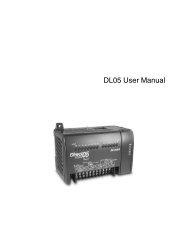
Figure 1-1: General View of <strong>2704</strong> Controller<br />
Other features include:<br />
• A wide variety of inputs which can be configured, including thermocouples, Pt100<br />
resistance thermometers <strong>and</strong> high level process inputs.<br />
• Direct connection of zirconia oxygen probes is also supported for use in heat treatment<br />
furnaces <strong>and</strong> ceramic kiln applications.<br />
• Each loop can be defined to be PID, On/Off or motorised valve position <strong>and</strong> can control<br />
using a variety of strategies including single, cascade, override <strong>and</strong> ratio control.<br />
• PID control outputs can be relay, logic, triac or dc with motorised valve position outputs<br />
being relay triac or logic.<br />
• Auto tuning <strong>and</strong> PID gain scheduling are available to simplify commissioning <strong>and</strong><br />
optimise the process<br />
Configuration of the <strong>controller</strong> is explained in a separate Engineering Manual, Part No.<br />
HA026933. Configuration is achieved either via the front panel operator interface or by<br />
using ‘iTools’ - a configuration package which runs under the Windows 95, or NT operating<br />
systems.<br />
Installation <strong>and</strong> Operation H<strong>and</strong>book. Part No HA026502 Issue 1.0 Apr-00 1-3
Introduction<br />
<strong>2704</strong> Controller<br />
1.3. BEFORE YOU BEGIN<br />
1.3.1. Unpacking<br />
All parts comprising the <strong>2704</strong> are boxed individually. The packaging is designed to<br />
withst<strong>and</strong> reasonable transit shocks. It is suggested that each item is unpacked carefully <strong>and</strong><br />
the contents inspected for damage.<br />
If there is evidence of shipping damage, please notify your supplier within 72 hours. The<br />
packaging should be retained for inspection.<br />
All packaging contains anti-static materials to prevent the build up of static which can<br />
damage electronic assemblies.<br />
1.3.2. Contents of Packaging<br />
Each box contains the following parts:-<br />
1. The <strong>2704</strong> <strong>controller</strong> fitted into its corresponding sleeve. Labels on the sleeve identify the<br />
<strong>controller</strong> code, its serial number, <strong>and</strong> the customer reference number. These details<br />
should be checked against your requirements before installing the unit into the panel. A<br />
description of the instrument code is given in Appendix A.<br />
2. Two panel retaining clips<br />
3. Burden resistors for use with mA inputs<br />
4. This Installation <strong>and</strong> Operation H<strong>and</strong>book<br />
Please refer to Figure 1-2 showing a general view of the <strong>controller</strong>.<br />
1.3.3. Does the Controller Match the Process?<br />
Every <strong>controller</strong> is supplied with a specific hardware configuration to match the process<br />
which it is designed to control. For example, there are five ‘slots’ which can contain different<br />
plug in modules. These are defined by a hardware code as shown in Appendix A. Before<br />
installing the <strong>2704</strong> <strong>controller</strong> check the label on the side of the instrument against the<br />
instrument coding given in Appendix A for correct type.<br />
Where possible the <strong>controller</strong> is supplied with its software configured to match the process.<br />
This is defined by a quick start order code given in Appendix A. This should also be checked<br />
on the instrument label to ensure that the <strong>controller</strong> is suitable for the process to be<br />
controlled.<br />
The <strong>2704</strong> <strong>controller</strong> contains a large number of variants to fulfil the dem<strong>and</strong>s of specific<br />
processes. In general the software configuration can be changed through the front panel of<br />
the <strong>controller</strong>. The procedures are described both in this manual <strong>and</strong> the Engineering<br />
Manual, Part No. HA026933. Alternatively, ‘iTools’ configuration software may be used to<br />
configure the <strong>controller</strong>. The order code for this is also shown in Appendix A.<br />
1-4 Installation <strong>and</strong> Operation H<strong>and</strong>book. Part No HA026502 Issue 1.0 Apr-00
<strong>2704</strong> Controller Introduction<br />
➃<br />
➂<br />
➇<br />
➇<br />
➅<br />
➆<br />
➁<br />
➀<br />
➄<br />
➁<br />
➃<br />
KEY<br />
➀<br />
➁<br />
➂<br />
➃<br />
➄<br />
➅<br />
➆<br />
➇<br />
Display screen<br />
Latching ears<br />
Panel sealing gasket<br />
Panel retaining clips<br />
Label<br />
Sleeve<br />
Terminal covers<br />
Ratchets<br />
Figure 1-2: General View of <strong>2704</strong> Controller<br />
Installation <strong>and</strong> Operation H<strong>and</strong>book. Part No HA026502 Issue 1.0 Apr-00 1-5
Introduction<br />
<strong>2704</strong> Controller<br />
1.4. OPERATOR INTERFACE - OVERVIEW<br />
The front panel of the <strong>2704</strong> consists of a 120 x 160 pixel electroluminscent display, <strong>and</strong><br />
seven operator push-buttons. See Figure 1-3.<br />
• The display is used to show the process conditions.<br />
• The seven operator buttons allow adjustments to be made to the <strong>controller</strong>.<br />
Alarm Beacon<br />
(appears at the<br />
left of the banner<br />
when an alarm is<br />
present)<br />
Programmer/<br />
Autotune status<br />
Setpoint<br />
Source<br />
Auto/Manual<br />
Loop Type<br />
Units or [SBY]<br />
PV<br />
SP<br />
Output level<br />
This is a view of<br />
Loop 1 Page<br />
Operator buttons<br />
Page button<br />
Scroll button<br />
Down button<br />
Up button<br />
Press to select a new list of parameters.<br />
Press to select a new parameter in a list.<br />
Press to decrease a parameter value.<br />
Press to increase a parameter value.<br />
Figure 1-3: Operator Interface<br />
1-6 Installation <strong>and</strong> Operation H<strong>and</strong>book. Part No HA026502 Issue 1.0 Apr-00
<strong>2704</strong> Controller Introduction<br />
1.4.1. Status Messages<br />
Messages appear on the display to show the current status of the <strong>controller</strong>. Table 1-1 below<br />
describes these messages:-<br />
LP1, LP2,<br />
LP3<br />
AUT<br />
MAN<br />
SP1, SP2,<br />
PO, REM<br />
CSD<br />
OVR<br />
RAT<br />
Indicates which loop is being viewed<br />
The selected loop is in automatic (closed loop) control<br />
The selected loop is in manual (open loop) control<br />
Indicates where the SP is derived, i.e. Setpoint 1, Setpoint 2, Programmer,<br />
Remote<br />
Indicates that the loop is in cascade.<br />
Indicates that the loop is in override.<br />
Indicates that the loop is in ratio (Ratio must be enabled from the parameter<br />
list at the bottom of the display)<br />
Indicates a program is activated<br />
Indicates a program is held at its current levels<br />
Indicates a program is in reset condition i.e. not running<br />
<br />
[UNITS]<br />
[SBY]<br />
When an alarm occurs an alarm symbol flashes in the header banner. When<br />
the alarm is acknowledged but is still active the symbol will be permanently lit.<br />
When the alarm is acknowledged but is no longer active the symbol will<br />
disappear.<br />
See Chapter 7 ‘Alarm Operation’ for further details.<br />
The process units are displayed in the right h<strong>and</strong> side of the banner<br />
This symbol will flash in the right h<strong>and</strong> side of the banner in place of ‘units’<br />
when the <strong>controller</strong> is in st<strong>and</strong>by mode. In this state all interfaces to the plant<br />
are switched to a rest condition. For example, all control outputs = 0.<br />
When this symbol is on the <strong>controller</strong> is no longer controlling the<br />
process.<br />
This symbol will be on when:-<br />
• The <strong>controller</strong> is in configuration mode<br />
• St<strong>and</strong>by mode has been selected through the user interface or via an<br />
external digital input<br />
• During the first few seconds after start up<br />
Table 1-1: Status Messages<br />
Installation <strong>and</strong> Operation H<strong>and</strong>book. Part No HA026502 Issue 1.0 Apr-00 1-7
Introduction<br />
<strong>2704</strong> Controller<br />
1.5. INSTALLATION - OVERVIEW<br />
The <strong>2704</strong> <strong>controller</strong> must be mounted <strong>and</strong> wired in accordance with the instructions given in<br />
Chapter 2.<br />
The <strong>controller</strong> is intended to be mounted through a cut out in the front panel of an electrical<br />
control cabinet. It is retained in position using the panel mounting clips supplied.<br />
All wires are connected to terminals at the rear of the instrument. Each block of six terminals<br />
is protected by a hinged cover which clicks into closed position.<br />
Digital<br />
I/O<br />
PV<br />
input<br />
DC<br />
D1<br />
D2<br />
D3<br />
D4<br />
D5<br />
D6<br />
D7<br />
VH<br />
VI<br />
V+<br />
V-<br />
M<br />
O<br />
D<br />
U<br />
L<br />
E<br />
4<br />
M<br />
O<br />
D<br />
U<br />
L<br />
E<br />
5<br />
M<br />
O<br />
D<br />
U<br />
L<br />
E<br />
6<br />
4A<br />
4B<br />
4C<br />
4D<br />
5A<br />
5B<br />
5C<br />
5D<br />
6A<br />
6B<br />
6C<br />
6D<br />
M<br />
O<br />
D<br />
U<br />
L<br />
E<br />
1<br />
*<br />
*<br />
*<br />
*<br />
M<br />
O<br />
D<br />
U<br />
L<br />
E<br />
3<br />
1A<br />
1B<br />
1C<br />
1D<br />
2A<br />
2B<br />
2C<br />
2D<br />
3A<br />
3B<br />
3C<br />
3D<br />
C<br />
O<br />
M<br />
M<br />
S<br />
M<br />
O<br />
D<br />
U<br />
L<br />
E<br />
H<br />
C<br />
O<br />
M<br />
M<br />
S<br />
M<br />
O<br />
D<br />
U<br />
L<br />
E<br />
J<br />
HA<br />
HB<br />
HC<br />
HD<br />
HE<br />
HF<br />
JA<br />
JB<br />
JC<br />
JD<br />
JE<br />
JF<br />
L<br />
N<br />
D8<br />
E1<br />
E2<br />
AA<br />
AB<br />
AC<br />
BA<br />
BB<br />
BC<br />
Power<br />
Supply<br />
Digital<br />
Input<br />
I/O<br />
Exp<strong>and</strong>er<br />
or Digital<br />
input<br />
Relay<br />
Analogue<br />
input<br />
0-10V<br />
Analogue<br />
input<br />
screen<br />
The functionality of the two outer rows of terminals is<br />
common to all instrument variants, as follows:-<br />
PV input VH, VI, V+, V-<br />
Analogue input<br />
BA, BB<br />
I/O exp<strong>and</strong>er<br />
E1, E2<br />
Fixed changeover relay AA, AB, AC<br />
Digital I/O channels D1 to D8 <strong>and</strong> DC<br />
Power supply<br />
L, N, Earth<br />
* Terminals 2A, 2B, 2C, 2D must not be wired to.<br />
Hinged<br />
cover in<br />
open<br />
position<br />
Figure 1-4: Rear Terminals<br />
1-8 Installation <strong>and</strong> Operation H<strong>and</strong>book. Part No HA026502 Issue 1.0 Apr-00
<strong>2704</strong> Controller Introduction<br />
1.6. I/O MODULES<br />
The <strong>2704</strong> <strong>controller</strong> has the facility to fit optional plug in modules. The connections for these<br />
modules are made to the inner three connector blocks as shown in Figure 1-4<br />
The modules are:<br />
• Communications modules. See also section 2.4<br />
• I/O modules See also section 2.5<br />
These modules are fitted simply by sliding them into the relevant position as shown in Figure<br />
1-5.<br />
Figure 1-5: View of the Plug-in Modules<br />
Installation <strong>and</strong> Operation H<strong>and</strong>book. Part No HA026502 Issue 1.0 Apr-00 1-9
Introduction<br />
<strong>2704</strong> Controller<br />
1-10 Installation <strong>and</strong> Operation H<strong>and</strong>book. Part No HA026502 Issue 1.0 Apr-00
<strong>2704</strong> Controller Installation<br />
2. CHAPTER 2 INSTALLATION ............................................. 2<br />
2.1. MECHANICAL INSTALLATION.........................................................2<br />
2.1.1. Positioning................................................................................................... 2<br />
2.1.2. Outline dimensions Model <strong>2704</strong> .................................................................. 2<br />
2.1.3. Mounting the Controller ............................................................................... 3<br />
2.1.4. Unplugging <strong>and</strong> Plugging in the Controller.................................................. 3<br />
2.2. WIRING...............................................................................................4<br />
2.2.1. Electrical Connections................................................................................. 4<br />
2.2.2. Rear Terminal Layout.................................................................................. 4<br />
2.3. STANDARD CONNECTIONS ............................................................6<br />
2.3.1. Power Supply Wiring (Line voltage) ............................................................ 6<br />
2.3.2. Relay Output ............................................................................................... 6<br />
2.3.3. Sensor Input Connections........................................................................... 7<br />
2.3.4. Analogue Input Connections ....................................................................... 8<br />
2.3.5. I/O Exp<strong>and</strong>er (or Additional Digital Input).................................................... 9<br />
2.3.6. Digital I/O................................................................................................... 10<br />
2.4. OPTIONAL PLUG IN MODULE CONNECTIONS ...........................11<br />
2.4.1. Digital Communications Connections........................................................ 11<br />
2.4.2. I/O Modules ............................................................................................... 13<br />
2.5. TO CONNECT ZIRCONIA (DUAL SIGNAL) PROBE ......................18<br />
2.5.1. Zirconia Probe Screening.......................................................................... 19<br />
Installation <strong>and</strong> Operation H<strong>and</strong>book. Part No HA026502 Issue 1.0 Apr-00 2-1
Installation<br />
<strong>2704</strong> Controller<br />
2. Chapter 2 INSTALLATION<br />
2.1. MECHANICAL INSTALLATION<br />
2.1.1. Positioning<br />
The <strong>controller</strong> can be mounted vertically or on a sloping panel of maximum thickness 15mm<br />
(0.6in). Adequate access space must be available at the rear of the instrument panel for<br />
wiring <strong>and</strong> servicing purposes. The outline dimensions are shown in figure 2-1.<br />
Take care not to cover ventilation holes in the top, bottom <strong>and</strong> sides of the instrument.<br />
Before proceeding please read Appendix B ‘Safety <strong>and</strong> EMC Information’.<br />
2.1.2. Outline dimensions Model <strong>2704</strong><br />
Panel thickness up<br />
to 12mm, 0.5in.<br />
Front<br />
Panel<br />
Height<br />
96mm<br />
(3.78in)<br />
Front panel<br />
width 96mm<br />
(3.78in)<br />
Overall depth behind<br />
panel 150mm<br />
(5.91in)<br />
Figure 2-1: Outline Dimensions<br />
2-2 Installation <strong>and</strong> Operation H<strong>and</strong>book Part No HA026502 Issue 1.0 Apr-00
<strong>2704</strong> Controller Installation<br />
2.1.3. Mounting the Controller<br />
1. Prepare the panel cut-out to the size shown in Figure 2-2. Ensure that there is sufficient<br />
spacing between instruments as shown by the minimum dimensions given in Figure 2-2.<br />
Ensure also that the <strong>controller</strong> is not mounted close to any device which is likely to<br />
produce a significant amount of heat which may affect the performance of the <strong>controller</strong>.<br />
2. Insert the <strong>controller</strong> through the panel cut-out.<br />
3. Spring the upper <strong>and</strong> lower panel retaining clips into place. Secure the <strong>controller</strong> in<br />
position by holding it level <strong>and</strong> pushing both retaining clips forward.<br />
Note:- If the retaining clips subsequently need removing, in order to extract the <strong>controller</strong><br />
from the control panel, they can be unhooked from the side with either your fingers or a<br />
screwdriver.<br />
Panel cut-out<br />
92 x 92 mm<br />
3.62 x 3.62 in<br />
-0<br />
+0.8<br />
-0<br />
+0.03<br />
Recommended<br />
minimum<br />
spacing of<br />
<strong>controller</strong>s<br />
10mm<br />
(0.4in)<br />
38mm<br />
(1.5in)<br />
(Not to<br />
scale)<br />
Figure 2-2: Panel Cut-out <strong>and</strong> Minimum Spacing Requirements<br />
2.1.4. Unplugging <strong>and</strong> Plugging in the Controller<br />
If required, the <strong>controller</strong> can be unplugged from its sleeve by easing the latching ears<br />
outwards <strong>and</strong> pulling the <strong>controller</strong> forward out of the sleeve. When plugging the <strong>controller</strong><br />
back into its sleeve, ensure that the latching ears click into place.<br />
It is recommended that the power to the <strong>controller</strong> is switched off when un-plugging or<br />
plugging the <strong>controller</strong> into its sleeve. This is to prevent premature wear on the <strong>controller</strong><br />
connectors when current is flowing through them.<br />
Installation <strong>and</strong> Operation H<strong>and</strong>book. Part No HA026502 Issue 1.0 Apr-00 2-3
Installation<br />
<strong>2704</strong> Controller<br />
2.2. WIRING<br />
WARNING<br />
You must ensure that the <strong>controller</strong> is correctly configured for your application.<br />
Incorrect configuration could result in damage to the process being controlled, <strong>and</strong>/or<br />
personal injury. It is your responsibility, as the installer, to ensure that the<br />
configuration is correct. The <strong>controller</strong> may either have been configured when ordered,<br />
or may need configuring now. See <strong>2704</strong> Engineering Manual Part Number HA026933 for<br />
details.<br />
Before proceeding further, please read Appendix B, Safety <strong>and</strong> EMC information.<br />
2.2.1. Electrical Connections<br />
All electrical connections are made to the screw terminals at the rear of the <strong>controller</strong>. They<br />
accept wire sizes from 0.5 to 1.5 mm 2 (16 to 22 AWG) <strong>and</strong> should be tightened to a torque of<br />
0.4Nm (3.5lbin). If you wish to use crimp connectors, the correct size is AMP part number<br />
349262-1. The terminals are protected by a clear plastic hinged cover to prevent h<strong>and</strong>s, or<br />
metal, making accidental contact with live wires.<br />
2.2.2. Rear Terminal Layout<br />
The rear terminal layout is shown in Figure 2-3, which identifies terminal designations <strong>and</strong><br />
their functions. Refer to the individual diagrams to wire the <strong>controller</strong> to your requirements.<br />
The two outer terminal strips have fixed hardware for all versions of the instrument, as<br />
follows:-<br />
• A Process Variable input which can be configured for:-<br />
• Thermocouple, RTD, Pyrometer, Voltage (e.g. 0-10Vdc) or Milliamp (e.g. 4-<br />
20mA) signals<br />
• Seven Digital I/O, configurable as input or output.<br />
• Inputs are logic (-1 to 35Vdc) or contact closure, <strong>and</strong> can be configured for:-<br />
Manual, Remote, Run, Hold, Reset, etc,.<br />
• Outputs are open collector requiring an external power supply, <strong>and</strong> can be<br />
configured as event, status time proportioning or valve position outputs.<br />
• One digital input<br />
• An I/O exp<strong>and</strong>er which allows additional digital I/O via an external unit.<br />
• A changeover relay which can be configured as an alarm or event output. It cannot be<br />
configured as a time proportioning output.<br />
• An analogue input for volts (e.g. 0-10Vdc) or Milliamp (e.g. 4-20mA) signals to a second<br />
PID loop, setpoint, etc,. (This input can be characterised to match a particular curve from<br />
a transmitter. It cannot accept thermocouple inputs directly).<br />
• Power supply to the unit. The supply may be 85 - 264Vac 50 or 60 Hz,<br />
The three central terminal strips are for optional plug in modules, as follows:-<br />
2-4 Installation <strong>and</strong> Operation H<strong>and</strong>book Part No HA026502 Issue 1.0 Apr-00
<strong>2704</strong> Controller Installation<br />
• Terminals marked 2A to 2D are reserved for a Memory Module only. No connections<br />
should be made to these terminals.<br />
• Terminals marked HA to HF are connections for optional RS232, RS485, or RS422<br />
communications modules.<br />
• Terminals marked JA to JF are connections for an optional slave communications module<br />
or second communications port used to communicate with other instruments.<br />
The modules fitted into the above two communications slots can be inter-changed.<br />
For a full list of available modules refer to the Ordering code - Appendix A <strong>and</strong> the Technical<br />
Specification - Appendix C. The functionality of these modules is given in subsequent<br />
chapters.<br />
!<br />
Caution, Warning:- (refer Take to the care that mains Functional supplies earth are connected only to the power supply<br />
accompanying terminals (85 documents) to 254Vac only), the (ground) fixed terminal relay terminals or to relay or triac<br />
modules. Under no circumstances should mains supplies be connected to any<br />
other terminals.<br />
Digital<br />
I/O<br />
PV<br />
input<br />
DC<br />
D1<br />
D2<br />
D3<br />
D4<br />
D5<br />
D6<br />
D7<br />
VH<br />
V1<br />
V+<br />
V-<br />
M<br />
O<br />
D<br />
U<br />
L<br />
E<br />
4<br />
M<br />
O<br />
D<br />
U<br />
L<br />
E<br />
5<br />
M<br />
O<br />
D<br />
U<br />
L<br />
E<br />
6<br />
4A<br />
4B<br />
4C<br />
4D<br />
5A<br />
5B<br />
5C<br />
5D<br />
6A<br />
6B<br />
6C<br />
6D<br />
M<br />
O<br />
D<br />
U<br />
L<br />
E<br />
1<br />
M<br />
O<br />
D<br />
U<br />
L<br />
E<br />
3<br />
1A<br />
1B<br />
1C<br />
1D<br />
2A<br />
2B<br />
2C<br />
2D<br />
3A<br />
3B<br />
3C<br />
3D<br />
C<br />
O<br />
M<br />
M<br />
S<br />
M<br />
O<br />
D<br />
U<br />
L<br />
E<br />
H<br />
C<br />
O<br />
M<br />
M<br />
S<br />
M<br />
O<br />
D<br />
U<br />
L<br />
E<br />
J<br />
HA<br />
HB<br />
HC<br />
HD<br />
HE<br />
HF<br />
JA<br />
JB<br />
JC<br />
JD<br />
JE<br />
JF<br />
L<br />
N<br />
D8<br />
E1<br />
E2<br />
AA<br />
AB<br />
AC<br />
BA<br />
BB<br />
BC<br />
Power<br />
Supply<br />
Digital<br />
Input<br />
I/O<br />
Exp<strong>and</strong>er<br />
or Digital<br />
input<br />
Relay<br />
Analogue<br />
input Hi<br />
Level eg<br />
0-10V<br />
Remote<br />
input<br />
screen<br />
Figure 2-3: Rear Terminal Connections<br />
Installation <strong>and</strong> Operation H<strong>and</strong>book. Part No HA026502 Issue 1.0 Apr-00 2-5
Installation<br />
<strong>2704</strong> Controller<br />
2.3. STANDARD CONNECTIONS<br />
2.3.1. Power Supply Wiring (Line voltage)<br />
The <strong>2704</strong> <strong>controller</strong> is suitable for connection to a power supply of between 85 <strong>and</strong> 264Vac<br />
50 or 60 Hz. It is the users responsibility to provide an external fuse or circuit breaker.<br />
Suitable fuses are T type (EN60127 time-lag type) rated at 1A<br />
85 to 264Vac Voltage Supply<br />
L<br />
N<br />
Line 85 to 264Vac<br />
Neutral<br />
Earth<br />
Figure 2-4: Wiring Connections For Line Voltage<br />
2.3.2. Relay Output<br />
A single changeover relay is provided as st<strong>and</strong>ard. It can be configured as a control output or<br />
an alarm or event output.<br />
Fixed relay connections<br />
AA<br />
AB<br />
AC<br />
Normally<br />
Open<br />
Common<br />
Normally<br />
Closed<br />
Figure 2-5: Wiring Connections For Fixed Relay Output<br />
2-6 Installation <strong>and</strong> Operation H<strong>and</strong>book Part No HA026502 Issue 1.0 Apr-00
<strong>2704</strong> Controller Installation<br />
2.3.3. Sensor Input Connections<br />
The fixed PV input can accept a range of sensors including Thermocouple, RTD (Pt100),<br />
Pyrometer, Voltage (e.g. 0-10Vdc) or Milliamp (e.g. 4-20mA) signals. These sensors are<br />
used to provide inputs to Control Loop 1.<br />
Thermocouple or Pyrometer<br />
Use the correct type of<br />
compensating cable<br />
to extend wiring<br />
+<br />
-<br />
VH<br />
VI<br />
V+<br />
V-<br />
RTD (Pt100)<br />
3-wire<br />
platinum<br />
resistance<br />
thermometer<br />
For 2-wire<br />
this is a<br />
local link<br />
VH<br />
VI<br />
V+<br />
V-<br />
Voltage 0 to 10V or 0 to 2V<br />
Current 0 to 20mA (4 to 20mA)<br />
+<br />
0 - 10<br />
Volt<br />
source<br />
-<br />
VH<br />
VI<br />
V+<br />
V-<br />
+<br />
Current<br />
source<br />
-<br />
2.49Ω<br />
resistor<br />
supplied<br />
VH<br />
VI<br />
V+<br />
V-<br />
mV (up to 80mV)<br />
VH<br />
+<br />
VI<br />
mVolt<br />
source<br />
V+<br />
-<br />
V-<br />
Figure 2-6: Wiring Connections For PV Input<br />
Installation <strong>and</strong> Operation H<strong>and</strong>book. Part No HA026502 Issue 1.0 Apr-00 2-7
Installation<br />
<strong>2704</strong> Controller<br />
2.3.4. Analogue Input Connections<br />
The analogue input is supplied as st<strong>and</strong>ard <strong>and</strong> is intended to accept 0 to 10 Vdc from a<br />
voltage source. A milli-amp current source can be used by connecting a 100Ω resistor across<br />
terminals BA <strong>and</strong> BB. This input can be used as a remote setpoint input, remote setpoint trim<br />
or as a high level PV input to a control loop. This input is not isolated from the digital IO.<br />
Non-isolated Voltage Source (0 to 10V)<br />
BA<br />
BB<br />
BC<br />
+<br />
-<br />
If screened cable is<br />
used earth at the supply<br />
end<br />
Nonisolated<br />
0 to<br />
10Vdc<br />
source<br />
Non-isolated Current Source (0 - 20mA) (4 - 20mA)<br />
BA<br />
BB<br />
BC<br />
+<br />
-<br />
100Ω<br />
If screened cable is<br />
used earth at the supply<br />
end<br />
Nonisolated<br />
current<br />
source<br />
Isolated Voltage Source (0 to 10V)<br />
BA<br />
BB<br />
BC<br />
+<br />
-<br />
Screen<br />
Isolated<br />
0 to<br />
10Vdc<br />
source<br />
Isolated Current Source (0 - 20mA) (4 - 20mA)<br />
BA<br />
BB<br />
BC<br />
+<br />
-<br />
100Ω<br />
Screen<br />
Isolated<br />
current<br />
source<br />
Figure 2-7: Wiring Connections For Analogue Input<br />
2-8 Installation <strong>and</strong> Operation H<strong>and</strong>book Part No HA026502 Issue 1.0 Apr-00
<strong>2704</strong> Controller Installation<br />
2.3.5. I/O Exp<strong>and</strong>er (or Additional Digital Input)<br />
The I/O exp<strong>and</strong>er is used with the <strong>2704</strong> to allow the number of I/O points to be increased by<br />
a further 20 digital inputs <strong>and</strong> 20 digital outputs. Data transfer is performed serially via a two<br />
wire interface from instrument to exp<strong>and</strong>er.<br />
If the exp<strong>and</strong>er unit is not required it is possible to use terminals E1 & E2 as a secondary<br />
digital input. These terminals are not part of the digital I/O on terminals D1 to D8 <strong>and</strong> if used<br />
in this way connect a 2K2, ¼ W limiting resistor in series with the input, as shown in Figure<br />
2-8.<br />
I/O exp<strong>and</strong>er connections<br />
E1<br />
E2<br />
Data<br />
transfer<br />
ƒ<br />
20 Inputs<br />
Exp<strong>and</strong>er<br />
20 Outputs<br />
…<br />
I/O exp<strong>and</strong>er connections<br />
E1<br />
E2<br />
Additional digital input if the<br />
exp<strong>and</strong>er is not used<br />
2K2<br />
+<br />
-<br />
Limits:<br />
-1V, +35V<br />
Figure 2-8: Wiring Connections for the I/O Exp<strong>and</strong>er<br />
Installation <strong>and</strong> Operation H<strong>and</strong>book. Part No HA026502 Issue 1.0 Apr-00 2-9
Installation<br />
<strong>2704</strong> Controller<br />
2.3.6. Digital I/O<br />
Eight digital I/O connections are provided as st<strong>and</strong>ard. They can be configured as:<br />
1. Inputs Run, Hold, Reset, Auto/Manual, etc, - logic or contact closure.<br />
2. Outputs Configurable as Control outputs, Programmer Events, Alarms, etc.<br />
Digital IO is not isolated from instrument ground.<br />
Digital Inputs (Logic Inputs or Contact Closure in any combination)<br />
Common<br />
Logic<br />
inputs (1)<br />
Contact<br />
closure<br />
inputs<br />
DC<br />
D1<br />
D2<br />
D3<br />
D4<br />
D5<br />
D6<br />
D7<br />
D8<br />
Common<br />
This terminal can be<br />
used for Digital<br />
Input only (not DO)<br />
Note 1:<br />
Logic inputs can accept drive signals from<br />
a voltage source where:<br />
4V = Inactive (0) Limit +35V<br />
This action is reversed if the input has<br />
been configured as ‘Inverted’<br />
Digital Outputs (Relay, Thyristor or SSR Drive in any combination)<br />
External power supply 10 to 35 Vdc.<br />
Each output is current limited to 40mA<br />
Relay<br />
+<br />
_<br />
Relay<br />
Outputs are<br />
open collector<br />
DC<br />
D1<br />
D2<br />
Relay<br />
Thyristor<br />
Unit<br />
SSR<br />
Thyristor<br />
Unit<br />
SSR<br />
D3<br />
D4<br />
D5<br />
D6<br />
D7<br />
Figure 2-9: Wiring Connections for Digital I/O<br />
2-10 Installation <strong>and</strong> Operation H<strong>and</strong>book Part No HA026502 Issue 1.0 Apr-00
<strong>2704</strong> Controller Installation<br />
2.4. OPTIONAL PLUG IN MODULE CONNECTIONS<br />
2.4.1. Digital Communications Connections<br />
Digital Communications modules can be fitted in two positions in the <strong>2704</strong> <strong>controller</strong>, (see<br />
also section 1.5). The connections being available on HA to HF <strong>and</strong> JA to JF depending on<br />
the position in which the module is fitted. The two positions could be used, for example, to<br />
communicate with ‘iTools’ configuration package on one position, <strong>and</strong> to a PC running a<br />
supervisory package on the second position.<br />
The connections shown in the following diagrams show RS232, 2-wire RS485, 4-wire RS422<br />
<strong>and</strong> master/slave comms to a second <strong>controller</strong>.<br />
The diagrams show connections for ‘bench top test’ wiring. For a full description of the<br />
<strong>installation</strong> of a communications link, including line resistors, see Communications<br />
H<strong>and</strong>book, Part No. HA026230, <strong>and</strong> EMC Installation Guide, part no. HA025464.<br />
RS232<br />
PC<br />
HA<br />
HB<br />
Rx<br />
Tx<br />
Com<br />
HC<br />
HD<br />
Common<br />
HE<br />
Rx<br />
HF<br />
Tx<br />
Figure 2-10: RS232 Communications Connections<br />
RS285 - 2 wire<br />
PC<br />
Connections ‘daisy<br />
chained’ to other<br />
instruments<br />
HA<br />
HB<br />
RS232 to<br />
RS485<br />
2-wire<br />
converter<br />
Rx Tx Com<br />
RxB TxB<br />
RxA Com TxA<br />
HC<br />
HD<br />
HE<br />
HF<br />
Common<br />
A(+)<br />
B(-)<br />
Figure 2-11: RS485 2- Wire Communications Connections<br />
Installation <strong>and</strong> Operation H<strong>and</strong>book. Part No HA026502 Issue 1.0 Apr-00 2-11
Installation<br />
<strong>2704</strong> Controller<br />
RS485 4-wire<br />
(or RS422)<br />
Connections ‘daisy<br />
chained’ to other<br />
instruments<br />
PC<br />
HA<br />
HB<br />
A’ (Rx+)<br />
Rx Tx Com<br />
RxB RxA<br />
Com<br />
TxB TxA<br />
RS232 to<br />
RS422/RS485<br />
4-wire<br />
converter<br />
HC<br />
HD<br />
HE<br />
B’ (Rx-)<br />
Common<br />
A(Tx+)<br />
HF<br />
B (Tx-)<br />
Figure 2-12: RS485 4-Wire Communications Connections<br />
Profibus<br />
Connections ‘daisy<br />
chained’ to other<br />
instruments<br />
HA<br />
HB<br />
Shield<br />
PC<br />
HC<br />
HD<br />
VP (+5V)<br />
Rx/Tx +ve<br />
Rx Tx Com<br />
RxB RxA<br />
Com<br />
TxA TxB<br />
RS232 to<br />
RS422/RS485<br />
4-wire<br />
converter<br />
HE<br />
HF<br />
Rx/Tx -ve<br />
Dig Grnd<br />
Twisted pairs<br />
HA<br />
HB<br />
Shield<br />
Last <strong>controller</strong> only<br />
requires terminating<br />
resistors<br />
390Ω<br />
220Ω<br />
390Ω<br />
HC<br />
HD<br />
HE<br />
HF<br />
VP (+5V)<br />
Rx/Tx +ve<br />
Rx/Tx -ve<br />
Dig Grnd<br />
Figure 2-13: Profibus Wiring Connections<br />
2-12 Installation <strong>and</strong> Operation H<strong>and</strong>book Part No HA026502 Issue 1.0 Apr-00
<strong>2704</strong> Controller Installation<br />
2.4.2. I/O Modules<br />
The <strong>2704</strong> <strong>controller</strong> contains five positions in which 4-terminal I/O modules can be fitted.<br />
These positions are marked Module 1, Module 3, Module 4, Module 5, Module 6, in Figure<br />
2-3. Module 2 is reserved for the Memory Module which can only be fitted in this position.<br />
To find out which modules are fitted check the ordering code which is found on a label on the<br />
side of the instrument.<br />
Any module, listed in this section, can be fitted in any position, except the PV input which is<br />
limited to positions 3 <strong>and</strong> 6 only. Care should be taken, therefore, to ensure that modules are<br />
fitted as expected from the order code. The instrument can be interrogated in ‘View Config’<br />
level to locate the positions in which the modules are fitted. See Chapter 4, Access Levels. If<br />
modules have been added, removed or changed it is recommended that this is recorded on the<br />
instrument code label.<br />
I/O Module<br />
2A, 264Vac<br />
max<br />
1mA 1V min<br />
Typical<br />
usage<br />
Heating,<br />
cooling,<br />
alarm,<br />
program<br />
event,<br />
valve raise,<br />
valve lower<br />
H/W<br />
Code<br />
Connections <strong>and</strong> examples of use<br />
Note: The order code <strong>and</strong> terminal number is pre-fixed by the module number.<br />
Module 1 is connected to terminals 1A, 1B, 1C, 1D; module 3 to 3A, 3B, 3C, 3D, etc.<br />
First relay<br />
Contactor<br />
Relay (2 pin)<br />
R2<br />
Relay<br />
A<br />
<strong>and</strong><br />
<strong>and</strong><br />
Panel lamp<br />
Dual Relay<br />
RR<br />
etc<br />
B<br />
Contactor<br />
Relay<br />
Panel lamp<br />
etc<br />
Voltage<br />
supply<br />
C<br />
D<br />
Second relay<br />
(dual relay only)<br />
Change Over<br />
Relay<br />
(2A, 264Vac<br />
max)<br />
Heating,<br />
cooling,<br />
alarm,<br />
program<br />
event, valve<br />
raise, valve<br />
lower<br />
R4<br />
Contactor<br />
Relay<br />
Panel lamp<br />
etc<br />
Voltage<br />
supply<br />
A<br />
B<br />
C<br />
D<br />
Triple Logic<br />
Output<br />
(18Vdc at<br />
8mA max.)<br />
Heating,<br />
cooling,<br />
program<br />
events<br />
TP<br />
SSR or<br />
thyristor<br />
unit<br />
+<br />
Output A<br />
Output B<br />
Output C<br />
+<br />
+<br />
+<br />
A<br />
B<br />
C<br />
+ _<br />
-<br />
Common<br />
_<br />
D<br />
Installation <strong>and</strong> Operation H<strong>and</strong>book. Part No HA026502 Issue 1.0 Apr-00 2-13
Installation<br />
<strong>2704</strong> Controller<br />
I/O Module<br />
Typical<br />
usage<br />
H/W<br />
Code<br />
Connections <strong>and</strong> examples of use<br />
Triac<br />
<strong>and</strong> Dual<br />
Triac<br />
(0.7A, 30 to<br />
264Vac<br />
combined<br />
rating)<br />
Heating,<br />
cooling,<br />
valve raise,<br />
valve lower<br />
T2<br />
<strong>and</strong><br />
TT<br />
Motorised<br />
valve<br />
Raise<br />
Voltage<br />
supply<br />
Lower<br />
First triac<br />
A<br />
B<br />
C<br />
D<br />
Second triac<br />
Note: Dual relay modules may be used in place<br />
of dual triac.<br />
Note:-<br />
The combined current rating for the two<br />
triacs must not exceed 0.7A.<br />
DC Control<br />
(10Vdc, 20mA<br />
max)<br />
Heating,<br />
cooling<br />
e.g. to a<br />
4-20mA<br />
process<br />
actuator<br />
D4<br />
Actuator<br />
A +<br />
0-20mA<br />
or<br />
B<br />
0-10Vdc -<br />
C<br />
D<br />
DC Retransmission<br />
(10Vdc, 20mA<br />
max)<br />
Logging of<br />
PV, SP,<br />
output<br />
power, etc.,<br />
(0 to 10Vdc,<br />
or<br />
0 to 20mA)<br />
D6<br />
To other<br />
<strong>controller</strong>s<br />
0-20mA<br />
or<br />
0-10Vdc<br />
A<br />
B<br />
C<br />
D<br />
+<br />
-<br />
2-14 Installation <strong>and</strong> Operation H<strong>and</strong>book Part No HA026502 Issue 1.0 Apr-00
<strong>2704</strong> Controller Installation<br />
I/O Module<br />
Typical<br />
usage<br />
Order<br />
Code<br />
Connections <strong>and</strong> examples of use<br />
PV Input<br />
(Modules<br />
3 & 6 only)<br />
Second or<br />
third PV<br />
input<br />
PV<br />
3-wire RTD<br />
A<br />
Thermocouple<br />
A<br />
<strong>and</strong><br />
mV, V, mA,<br />
TC,<br />
RTD (Pt100)<br />
Zirconia<br />
probe<br />
B<br />
C<br />
D<br />
+<br />
-<br />
B<br />
C<br />
D<br />
Analogue<br />
Input<br />
(Modules<br />
1, 3, 4 & 6<br />
only)<br />
Second or<br />
third PV<br />
input<br />
mV, mA,<br />
TC,<br />
RTD (Pt100)<br />
AM<br />
For 2-wire this<br />
is a local link<br />
mV (up to 80mV)<br />
+<br />
A<br />
B<br />
mVolt<br />
source<br />
C<br />
-<br />
D<br />
Voltage 0 to 10V or 0 to 2V<br />
+<br />
0 - 10<br />
Volt<br />
source<br />
-<br />
A<br />
B<br />
C<br />
D<br />
Current 0 to 20mA (4 to 20mA)<br />
+<br />
Current<br />
source<br />
-<br />
2.49Ω<br />
resistor<br />
supplied<br />
A<br />
B<br />
C<br />
D<br />
Installation <strong>and</strong> Operation H<strong>and</strong>book. Part No HA026502 Issue 1.0 Apr-00 2-15
Installation<br />
<strong>2704</strong> Controller<br />
I/O Module<br />
Typical<br />
usage<br />
Order<br />
Code<br />
Connections <strong>and</strong> examples of use<br />
Triple Logic<br />
Input<br />
Events<br />
e.g. Program<br />
Run, Reset,<br />
Hold<br />
TL<br />
Logic inputs<br />
10.8V ON<br />
Limits:<br />
-3V, +30V<br />
Input 1<br />
Input 2<br />
Input 3<br />
Common<br />
A<br />
B<br />
C<br />
D<br />
Triple<br />
Contact<br />
Input<br />
Events<br />
e.g. Program<br />
Run, Reset,<br />
Hold<br />
TK<br />
External<br />
Switches or<br />
Relays<br />
Contact<br />
inputs<br />
28K* OFF<br />
Input 1<br />
Input 2<br />
Input 3<br />
Common<br />
A<br />
B<br />
C<br />
D<br />
24V<br />
Transmitter<br />
Supply<br />
To power an<br />
external<br />
transmitter<br />
MS<br />
Transmitter<br />
+<br />
-<br />
A<br />
B<br />
(20mA)<br />
C<br />
D<br />
2-16 Installation <strong>and</strong> Operation H<strong>and</strong>book Part No HA026502 Issue 1.0 Apr-00
<strong>2704</strong> Controller Installation<br />
Transducer<br />
Power<br />
Supply<br />
Provide 5V<br />
or 10Vdc to<br />
power Strain<br />
Gauge<br />
Transducer<br />
G3<br />
or<br />
G5<br />
C<br />
External calibration<br />
resistor (may be fitted<br />
in transducer).<br />
To<br />
Fixed<br />
or<br />
Module<br />
PV<br />
Input<br />
B<br />
A<br />
+<br />
_<br />
A<br />
B<br />
C<br />
D<br />
D<br />
Note: To minimise noise pick up it is<br />
recommended that screened cables are used for<br />
strain guage power supply connections.<br />
Potentiometer<br />
Input<br />
(100Ω to<br />
15KΩ)<br />
Motorised<br />
valve<br />
position<br />
feedback<br />
Remote SP<br />
VU<br />
+0.5v<br />
Wiper<br />
0v<br />
A<br />
B<br />
C<br />
D<br />
Dual PV<br />
Input<br />
(Modules 3<br />
& 6 only)<br />
To accept<br />
two inputs<br />
from a high<br />
level <strong>and</strong> a<br />
low level<br />
source.<br />
The two<br />
inputs are<br />
not isolated<br />
from each<br />
other.<br />
DP<br />
Current<br />
source<br />
+<br />
-<br />
+<br />
-<br />
Current<br />
source<br />
2.49Ω<br />
0-2V<br />
input<br />
100Ω<br />
0-20mA<br />
input<br />
The common connections to terminal D must be<br />
returned separately to D as shown in the dual<br />
current example above.<br />
A<br />
B<br />
C<br />
D<br />
Figure 2-14: Wiring Connections for IO Modules<br />
Installation <strong>and</strong> Operation H<strong>and</strong>book. Part No HA026502 Issue 1.0 Apr-00 2-17
Installation<br />
<strong>2704</strong> Controller<br />
2.5. TO CONNECT ZIRCONIA (DUAL SIGNAL) PROBE<br />
A dual signal probe, such as a Zirconia probe, will normally be connected to a Dual PV Input<br />
module (Code DP). The module presents two channels, A <strong>and</strong> C, where A is the voltage<br />
input <strong>and</strong> C is the mV, thermocouple, RTD or mA input.<br />
Example 1 shown below uses the Dual PV Input module with both channels configured. In<br />
this configuration the module runs at 4.5Hz. The two channels are un-isolated from oneanother<br />
but isolated from the rest of the instrument.<br />
Example 2 uses two modules. The modules can either be two PV Input modules (code PV)<br />
or a Dual PV Input module (code DP) with Channel C configured as ‘None’ plus a PV Input<br />
module. This combination runs at 9Hz <strong>and</strong> may be used if the loop is unusually fast.<br />
I/O Module<br />
Dual PV<br />
Input<br />
Typical<br />
usage<br />
Zirconia<br />
probe<br />
Order<br />
Code<br />
DP<br />
Connections <strong>and</strong> examples of use<br />
Example 1:- Using the Dual PV Input Module.<br />
Channel C is shown configured for thermocouple.<br />
The temperature sensor of a zirconia probe is<br />
connected to this input, terminals C & D. The<br />
Volt Source is connected to the A channel,<br />
terminals A & D.<br />
-<br />
Zirconia<br />
Volt<br />
source +<br />
+<br />
-<br />
Note: The +ve of the volt<br />
source must be connected to<br />
the-ve of the thermocouple.<br />
A<br />
B<br />
C<br />
D<br />
Two PV<br />
Input<br />
Modules<br />
PV<br />
Example 2:- Using Two Modules<br />
The temperature sensor of the zirconia probe can<br />
be connected to the precision PV input of one I/O<br />
module, connections C & D, with the Volt Source<br />
connected to the second module, terminals A &<br />
D.<br />
A<br />
+<br />
Zirconia<br />
B<br />
Volt<br />
+<br />
source<br />
C<br />
C<br />
-<br />
D<br />
D<br />
-<br />
For further information see Chapter 10.<br />
Figure 2-15: Wiring Connections for Zirconia Probe<br />
2-18 Installation <strong>and</strong> Operation H<strong>and</strong>book Part No HA026502 Issue 1.0 Apr-00
<strong>2704</strong> Controller Installation<br />
2.5.1. Zirconia Probe Screening<br />
2.5.1.1. Zirconia Carbon Probe Construction<br />
Hot End<br />
Zirconia<br />
Sensor<br />
Outer Electrode<br />
Ceramic Insulator<br />
Inner Electrode<br />
Outer metallic shell of the probe<br />
Screen<br />
-<br />
Zirc. mV<br />
+<br />
+<br />
Thermocouple<br />
-<br />
2.5.1.2. Screening connections when two modules are used<br />
The zirconia sensor wires should be screened <strong>and</strong> connected to the outer shell of the probe if<br />
it is situated in an area of high interference.<br />
A<br />
+<br />
B<br />
Outer Electrode<br />
Inner Electrode<br />
Screen<br />
Zirc. mV<br />
+<br />
-<br />
+<br />
Screened Cable<br />
-<br />
C<br />
D<br />
A<br />
T.C.<br />
-<br />
+<br />
B<br />
C<br />
-<br />
D<br />
2.5.1.3. Screening connections when a dual input module is used<br />
Both the thermocouple <strong>and</strong> the zirconia sensor wires must be screened <strong>and</strong> connected to the<br />
outer shell of the probe if it is situated in an area of high interference.<br />
Note the reverse connection of the zirconia sensor .<br />
Outer Electrode<br />
Inner Electrode<br />
Screen<br />
Zirc. mV<br />
T.C.<br />
+<br />
-<br />
-<br />
+<br />
Screened Cable<br />
Screened Compensating Cable<br />
-<br />
+<br />
+<br />
-<br />
A<br />
B<br />
C<br />
D<br />
Installation <strong>and</strong> Operation H<strong>and</strong>book. Part No HA026502 Issue 1.0 Apr-00 2-19
Installation<br />
<strong>2704</strong> Controller<br />
2-20 Installation <strong>and</strong> Operation H<strong>and</strong>book Part No HA026502 Issue 1.0 Apr-00
<strong>2704</strong> Controller Getting Started<br />
3. CHAPTER 3 GETTING STARTED ...................................... 2<br />
3.1. POWER UP ..................................................................................................3<br />
3.1.1. The HOME Page.........................................................................................3<br />
3.2. THE OPERATOR BUTTONS....................................................................4<br />
3.3. THE PROG BUTTON.................................................................................5<br />
3.4. THE LOOP SELECT BUTTON.................................................................5<br />
3.5. THE AUTO MANUAL BUTTON..............................................................6<br />
3.5.1. To Change Setpoint (when the loop is in Auto) ..........................................7<br />
3.5.2. To Change Output Power (when the loop is in Manual) .............................7<br />
3.6. PARAMETERS AND HOW TO ACCESS THEM ..................................8<br />
3.6.1. Pages ...........................................................................................................8<br />
3.7. NAVIGATION OVERVIEW......................................................................9<br />
3.7.1. To Select a Page Header .............................................................................9<br />
3.7.2. To Navigate to a Parameter from a Page Header. .....................................10<br />
3.7.3. To Change Next Parameter in the List ......................................................11<br />
3.7.4. To Change Any Parameter in the List .......................................................11<br />
3.8. BACKSCROLL..........................................................................................11<br />
3.9. PARAMETER VALUES...........................................................................12<br />
3.9.1. Confirmation Mechanism..........................................................................13<br />
3.9.2. Invalid key actions ....................................................................................13<br />
3.10. PARAMETER TABLES .........................................................................14<br />
3.11. DISPLAYS FOR CASCADE, RATIO AND OVERRIDE....................15<br />
3.12. PARAMETER AVAILABILITY AND ALTERABILITY...................18<br />
3.13. NAVIGATION DIAGRAM……………………………………………….19<br />
Installation <strong>and</strong> Operation H<strong>and</strong>book. Part No HA026502 Issue 1.0 Apr-00 3-1
Getting Started <strong>2704</strong> Controller<br />
3. Chapter 3 GETTING STARTED<br />
With the <strong>controller</strong> installed, as described in the previous chapter, this chapter explains the<br />
principle of how to locate <strong>and</strong> change values of parameters using the front panel buttons.<br />
Operation of these buttons changes the information on the display by opening different pages.<br />
Each page is associated with a particular aspect of the <strong>operation</strong> of the <strong>controller</strong>. The<br />
navigation between the pages follows a set order <strong>and</strong> the principle of this navigation is<br />
described in this chapter.<br />
Subsequent chapters describe the detail of each page <strong>and</strong> follow the order in which the pages<br />
appear on the <strong>controller</strong>.<br />
Note: The <strong>2704</strong> <strong>controller</strong> is an application specific <strong>controller</strong> <strong>and</strong> can be configured to<br />
the preferences of a particular process, site or user. This means that the displays shown<br />
in this <strong>and</strong> following chapters may not be identical to those shown in your instrument.<br />
Where the text on a display is user configurable it is shown in italics, eg Loop1<br />
About this chapter<br />
This chapter describes:<br />
◊ How to change setpoint<br />
◊ The operator buttons<br />
◊ Parameters <strong>and</strong> how to access them<br />
◊ Pages<br />
◊ How to step through pages<br />
◊ How to step through parameters<br />
◊ How to change parameter values<br />
◊ The navigation diagram<br />
◊ Parameter tables<br />
3-2 Installation <strong>and</strong> Operation H<strong>and</strong>book. Part No HA026502 Issue 1.0 Apr-00
<strong>2704</strong> Controller Getting Started<br />
3.1. POWER UP<br />
Install <strong>and</strong> wire up the <strong>controller</strong> in accordance with Chapter 2 <strong>and</strong> switch on. A short self<br />
test sequence takes place during which the <strong>controller</strong> identification is displayed together with<br />
the version number of software fitted.<br />
3.1.1. The HOME Page<br />
The <strong>controller</strong> then shows a default display, referred to as the HOME page. It is possible to<br />
configure the HOME page to suit the preferences of the process or the user, but the format is<br />
shown in Figure 3-1. This is also the default display on a new <strong>controller</strong>.<br />
The HOME page will be displayed under the following conditions:-<br />
1. When the <strong>controller</strong> is switched on<br />
2. When the access mode is changed from configuration level to an operating level<br />
3. When <strong>and</strong> are pressed together (see 3.10)<br />
4. When a timeout (if configured) occurs<br />
The HOME page can be configured as:-<br />
1. Summary Page (see also Chapter 5)<br />
2. The Program Run page (see also Chapter 6)<br />
3. Loop Views - LP1 (as shown), LP2, LP3<br />
4. The Access page (see Chapter 4)<br />
5. Cycle Each Loop. LP1 to LP3 pages are cycled in turn<br />
6. All Loops (summary of 2 or 3 loops if configured)<br />
7. LP1, LP2, LP3 Trend Charts (PV & SP for each loop)<br />
8. Program Mimic<br />
The configuration of these displays is described in the Engineering manual, Part No.<br />
HA026933.<br />
Message Banner<br />
Programmer<br />
Status<br />
Auto/Manual<br />
Setpoint source<br />
Output<br />
PV<br />
SP<br />
Loop 1<br />
Loop 2<br />
Loop 3<br />
Figure 3-1: The 'HOME' Page (default)<br />
Installation <strong>and</strong> Operation H<strong>and</strong>book. Part No HA026502 Issue 1.0 Apr-00 3-3
Getting Started <strong>2704</strong> Controller<br />
3.2. THE OPERATOR BUTTONS<br />
AUTO LOOP PROG<br />
AUTO<br />
LOOP<br />
Auto/Manual<br />
button<br />
Loop select<br />
button<br />
Programmer<br />
button<br />
When pressed, this toggles between automatic <strong>and</strong><br />
manual mode:<br />
• If the <strong>controller</strong> is in automatic mode ‘AUT’ is displayed<br />
• If the <strong>controller</strong> is in manual mode, ‘MAN’ is displayed<br />
See Figure 3-1<br />
Each press selects each loop in turn or between each<br />
loop <strong>and</strong> the trend chart if each of the above options are<br />
configured plus a summary of all loops.<br />
The loop name is shown in the banner at the top of the<br />
display<br />
• Press once to display a pop up window<br />
PROG<br />
This button<br />
operates the<br />
programmer<br />
on all loops<br />
See also<br />
Chapter 6<br />
‘Programmer<br />
Operation’<br />
The pop up window will remain for approximately 6<br />
seconds <strong>and</strong> during this period:-<br />
• Press PROG again to RUN a program<br />
• Press PROG again to HOLD a program<br />
• Press PROG again to toggle between RUN & HOLD<br />
Page button<br />
Scroll button<br />
Down button<br />
Up button<br />
• Press PROG <strong>and</strong> hold for two seconds to reset<br />
Press to select new pages from the page header ‘Menu’.<br />
If held down it will continuously scroll the pages.<br />
Press to select a new parameter from the page heading.<br />
If held down it will continuously scroll through the<br />
parameters.<br />
Press to decrease an analogue value, or to change the<br />
state of a digital value<br />
Press to increase an analogue value, or to change the<br />
state of a digital value<br />
Note:- The AUTO, LOOP, or PROG may have been disabled in configuration level.<br />
Figure 3-2: Operator Buttons<br />
3-4 Installation <strong>and</strong> Operation H<strong>and</strong>book. Part No HA026502 Issue 1.0 Apr-00
<strong>2704</strong> Controller Getting Started<br />
3.3. THE PROG BUTTON<br />
If the <strong>controller</strong> is configured as a programmer this button has three functions:<br />
• To put the programmer into RUN mode. This causes the working setpoint to follow the<br />
profile set in the program being used.<br />
• To put the programmer into HOLD mode. This stops the program from running <strong>and</strong><br />
maintains the setpoint at the current level..<br />
• To put the programmer into RESET mode. This resets the programmer to the <strong>controller</strong><br />
setpoint, the working setpoint can be changed manually using the Raise/Lower buttons.<br />
This button operates all programmer setpoints simultaneously.<br />
3.4. THE LOOP SELECT BUTTON<br />
If more than one loop is configured, the Loop Select button allows you to select a summary<br />
of each loop from whatever page is being displayed at the time. Each press of the Loop<br />
Select button will change the display from the ‘ALL LOOPS’ view to ‘Loop 1’ summary to<br />
the ‘Loop 1 Trend’ chart, followed by the next loop summary, <strong>and</strong> so on.<br />
By default a loop is designated by the mnemonic ‘LP’ followed by the loop number (1, 2 or<br />
3). This is shown in the banner at the top of the display page. The default message may be<br />
replaced by a customised name for the loop.<br />
To return to the original page view at any time, press the page button, . Alternatively, a<br />
timeout may have been set which will return the display to the HOME page view after a set<br />
period. The timeout is set in configuration level, see Engineering Manual part no HA026933.<br />
If only one loop is configured the display toggles between ‘LP1’ <strong>and</strong> ‘LP1 Trend’, (the ‘ALL<br />
LOOPS’ page is not shown).<br />
Press<br />
LOOP<br />
Press<br />
LOOP<br />
Next Loop<br />
Summary<br />
Back to ALL<br />
LOOPS summary<br />
Figure 3-3: Loop Summary <strong>and</strong> Loop Trend Chart<br />
Installation <strong>and</strong> Operation H<strong>and</strong>book. Part No HA026502 Issue 1.0 Apr-00 3-5
Getting Started <strong>2704</strong> Controller<br />
3.5. THE AUTO MANUAL BUTTON<br />
The <strong>controller</strong> has two basic modes of <strong>operation</strong>:<br />
• Automatic Mode in which the control output is automatically adjusted to maintain the<br />
process value at the setpoint .<br />
• Manual Mode in which you can adjust the output independently of the setpoint.<br />
The Auto/Manual button can only be operated from the loop view. Press the Loop Select<br />
button to select the loop view, then press AUTO/MAN to toggle between auto <strong>and</strong> manual.<br />
When the <strong>controller</strong> is in AUTO, ‘AUT’ will be displayed on the page (see Figure 3-4). The<br />
middle readout will default to the Working Setpoint in a st<strong>and</strong>ard <strong>controller</strong>.<br />
When the <strong>controller</strong> is in MANUAL, ‘MAN’ will be displayed on the page (see Figure 3-5).<br />
The middle readout will default to Output Power in a st<strong>and</strong>ard <strong>controller</strong>.<br />
If the loop summary page is not being viewed when the AUTO/MAN button is pressed, the<br />
display will change to the first available loop summary. Subsequent presses will change<br />
between Auto <strong>and</strong> Manual for the selected loop as above.<br />
If the output is configured as On/Off, the output will be Off when the target output < 0.9 <strong>and</strong><br />
On when the target output is > +1.0.<br />
3-6 Installation <strong>and</strong> Operation H<strong>and</strong>book. Part No HA026502 Issue 1.0 Apr-00
<strong>2704</strong> Controller Getting Started<br />
3.5.1. To Change Setpoint (when the loop is in Auto)<br />
A flashing bar underlines the<br />
selected parameter (setpoint)<br />
Press <strong>and</strong> hold the<br />
button to<br />
decrease the setpoint<br />
Press <strong>and</strong> hold the<br />
button to<br />
increase the setpoint<br />
Figure 3-4: Changing Setpoint<br />
3.5.2. To Change Output Power (when the loop is in Manual)<br />
A flashing bar underlines the selected<br />
parameter (output power)<br />
Press <strong>and</strong> hold the<br />
button to<br />
decrease the output<br />
Press <strong>and</strong> hold the<br />
button to<br />
increase the output<br />
Figure 3-5: Changing Output Power<br />
Installation <strong>and</strong> Operation H<strong>and</strong>book. Part No HA026502 Issue 1.0 Apr-00 3-7
Getting Started <strong>2704</strong> Controller<br />
3.6. PARAMETERS AND HOW TO ACCESS THEM<br />
Parameters are settings, within the <strong>controller</strong>, which determine how the <strong>controller</strong> will<br />
operate. They are accessed, using the <strong>and</strong> buttons, <strong>and</strong> can be changed, to suit the<br />
process, using the <strong>and</strong> buttons.<br />
Selected parameters may be protected under different security access levels.<br />
Examples of parameters are:-<br />
Values - such as setpoints, alarm trip levels, high <strong>and</strong> low limits, etc.,<br />
or<br />
States - such as auto/manual, on/off, etc. These are often referred to as enumerated values.<br />
3.6.1. Pages<br />
The parameters are organised into different pages. A page shows information such as page<br />
headers, parameter names <strong>and</strong> parameter values.<br />
Parameters are grouped in accordance with the function they perform. Each group is given a<br />
‘Page Header’ which is a generic description of the parameter group. Examples are ‘The<br />
Alarm Page’, ‘The Programmer Page’, etc,. A complete list of these is shown in the full<br />
navigation diagram, Section 3.13.<br />
Where a function has many parameters associated with it, the Page Header may be further sub<br />
divided into ‘Sub-Headers’. The parameters are then found under this category.<br />
Page Header<br />
Sub- Header<br />
Press to<br />
move to a ‘lower’<br />
level<br />
Press to<br />
return to a<br />
‘higher’ level<br />
Parameters<br />
Figure 3-6: Page Types<br />
It is possible to configure different start up pages as the Home page, but the principle of<br />
navigation is the same for all pages.<br />
Note:-<br />
A page only appears on the <strong>controller</strong> if the function has been ordered <strong>and</strong> has been<br />
enabled in Configuration mode. For example, if a programmer is not configured the<br />
RUN page <strong>and</strong> the EDIT PROGRAM pages will not be displayed.<br />
3-8 Installation <strong>and</strong> Operation H<strong>and</strong>book. Part No HA026502 Issue 1.0 Apr-00
<strong>2704</strong> Controller Getting Started<br />
3.7. NAVIGATION OVERVIEW<br />
3.7.1. To Select a Page Header<br />
Do This<br />
This Is The Display You Should<br />
See<br />
Additional Notes<br />
1. From any display<br />
press as many<br />
times as necessary to<br />
access the page<br />
header menu<br />
The vertical bar on the right<br />
of the display indicates the<br />
position of the page header.<br />
2. Press to scroll<br />
down the list of page<br />
headers.<br />
When the vertical bar<br />
reaches the centre of the<br />
screen the text moves up.<br />
This feature allows you to<br />
see previous <strong>and</strong><br />
following page header<br />
names.<br />
3. Press to scroll<br />
back up the list of<br />
page headers.<br />
When the last name in<br />
the Page Header list<br />
appears at the bottom of<br />
the display, the vertical<br />
bar <strong>and</strong> the highlighted<br />
text will continue move<br />
downwards.<br />
The sequence is repeated<br />
following further presses of<br />
button<br />
Installation <strong>and</strong> Operation H<strong>and</strong>book. Part No HA026502 Issue 1.0 Apr-00 3-9
Getting Started <strong>2704</strong> Controller<br />
3.7.2. To Navigate to a Parameter from a Page Header.<br />
Do This<br />
1. From any page press<br />
as many times as<br />
necessary to select the<br />
list of Page Headers<br />
2. Press or to<br />
scroll up or down the list<br />
of page headers.<br />
3. Press to select<br />
the list of Page Sub-<br />
Headers for the<br />
highlighted Page Header.<br />
4. Press or to<br />
scroll up or down the list<br />
of page sub-headers<br />
This Is The Display You Should<br />
See<br />
Press<br />
Press<br />
Additional Notes<br />
The symbol indicates<br />
that the page header is<br />
followed by a list of subheaders.<br />
to return to Page Header<br />
If a page does not<br />
contain a Sub-Header<br />
the display goes directly<br />
to 5 below<br />
to return to Sub- Header<br />
5. Press to select the<br />
list of Parameters in the<br />
highlighted sub-header.<br />
6. Press or to<br />
scroll up or down the list of<br />
parameters.<br />
7. Press to select<br />
the parameter which you<br />
wish to change<br />
8. Press or to<br />
change the value<br />
Press<br />
to return<br />
A flashing bar underlines<br />
the selected parameter.<br />
The parameter can only<br />
be altered if the value is<br />
preceded by !<br />
If the value is read only it<br />
will be replaced by ‘- -‘<br />
for as long as the raise or<br />
lower buttons are<br />
pressed<br />
3-10 Installation <strong>and</strong> Operation H<strong>and</strong>book. Part No HA026502 Issue 1.0 Apr-00
<strong>2704</strong> Controller Getting Started<br />
3.7.3. To Change Next Parameter in the List<br />
This sections describes how to select further parameters in the list which you may wish to<br />
alter or to view.<br />
Do This<br />
This Is The Display You Should<br />
See<br />
Additional Notes<br />
1. From the previous<br />
display, press to<br />
select the next parameter<br />
which you wish to<br />
change<br />
2. Press or to<br />
change the value<br />
The button will allow<br />
you to scroll down the list.<br />
If this button is held down<br />
it will continuously scroll<br />
around the list, which will<br />
enable you to change a<br />
previous parameter.<br />
3.7.4. To Change Any Parameter in the List<br />
As stated above you can keep pressing or hold down the button to continuously scroll<br />
around the list of parameters. There are two other alternatives. The first is to return to the<br />
highlight bar, described below. The second is ‘Backscroll’ described in the next section.<br />
Do This<br />
1. From the previous<br />
display, press to<br />
highlight the parameter<br />
value <strong>and</strong> its name.<br />
This Is The Display You Should<br />
See<br />
Additional Notes<br />
2. Press or to<br />
scroll up or down the list.<br />
3.8. BACKSCROLL<br />
In some cases it may be more convenient to scroll back up the list, for example, to select a<br />
new segment number when setting up a program.<br />
A short cut is provided by holding down <strong>and</strong> pressing or .<br />
Each press of will step back to the previous parameter. Each press of will step<br />
forward to the next parameter.<br />
This function is provided as a short cut <strong>and</strong> is not necessary to navigate through the<br />
parameters.<br />
Installation <strong>and</strong> Operation H<strong>and</strong>book. Part No HA026502 Issue 1.0 Apr-00 3-11
Getting Started <strong>2704</strong> Controller<br />
3.9. PARAMETER VALUES<br />
Parameter values can be displayed in different ways depending upon the parameter type. The<br />
different types of parameter, <strong>and</strong> how their values are changed, are shown below.<br />
1. Numerical Values (eg Full Scale High Alarm Setpoint)<br />
FS Hi Setpoint !200<br />
Press<br />
Press<br />
to increase the value<br />
to decrease the value<br />
2. Enumerated Values (eg PV Input Alarm Acknowledge)<br />
PV Alm Ack<br />
!No<br />
Press<br />
Press<br />
to show next state<br />
to show previous state<br />
3. Digital Values (e.g. programmer event outputs)<br />
Prog Reset DO ! æ<br />
Press to step along the values. A cursor under<br />
the selected value flashes.<br />
4. Parameter Addresses (eg PV Src )<br />
Press or to turn the value on or off<br />
PV Src !05108:PVIn.Val<br />
Press or to change the Parameter address.<br />
A cursor under the parameter address flashes.<br />
The parameter name for that address (if it exists) is<br />
shown to the right of the Modbus address.<br />
Press<br />
to change from parameter address to parameter mnemonic<br />
PV Src !05108:PVIn.Val<br />
Press or to change the parameter address by<br />
scrolling through a list of the most popular mnemonics.<br />
A cursor under the parameter mnemonic flashes.<br />
Note:- This example is only available in configuration level, but is included here to illustrate<br />
the principle of <strong>operation</strong>.<br />
3-12 Installation <strong>and</strong> Operation H<strong>and</strong>book. Part No HA026502 Issue 1.0 Apr-00
<strong>2704</strong> Controller Getting Started<br />
5. Text (eg Program Name - User definable)<br />
Program Name !Program 1 Press or to change the character<br />
Press<br />
to change to the next character<br />
Program Name !Program 1 Press or to change the character. Up to 16<br />
characters can be altered.<br />
6. Time (eg Programmer Segment Duration)<br />
Seg Duration !0:01:00<br />
Press or to increase or decrease the time setting.<br />
This is an accelerating display.<br />
Figure 3-7: Changing Parameter Values for Different Parameter Types<br />
3.9.1. Confirmation Mechanism<br />
Having changed a value, when the or key is released, the display will blink after a<br />
period of 1.5 seconds, indicating that the new parameter value has been accepted. If any<br />
other key is pressed during the 1.5 second period the parameter value is accepted<br />
immediately.<br />
There are exceptions for specific parameters. Examples of these are:-<br />
Output Power adjustment when in Manual mode. The value is written continuously as the<br />
value is changed.<br />
Alarm Acknowledge. If the Alarm Acknowledge is changed from ‘No’ to ‘Acknowledge’ a<br />
confirmation message appears. Press key to confirm the change. If no key is pressed for<br />
10 seconds the value is restored to its previous value.<br />
3.9.2. Invalid key actions<br />
At any time some state transitions may be invalid, due, for example, to contention with digital<br />
inputs or to the current operating state of the instrument.<br />
Examples are:-<br />
1. Digital inputs have priority over the operator buttons.<br />
2. If a parameter value cannot be changed the ! prompt is not shown<br />
3. If the or button is pressed for a read only parameter a number of dashes, ----, is<br />
displayed.<br />
Installation <strong>and</strong> Operation H<strong>and</strong>book. Part No HA026502 Issue 1.0 Apr-00 3-13
Getting Started <strong>2704</strong> Controller<br />
3.10. PARAMETER TABLES<br />
Subsequent chapters in this manual refer to parameter tables. These tables provide the full<br />
list of parameters available at Access Level 3 in a particular page. The table below is an<br />
example.<br />
Column 1 gives the name of the parameter as it appears on the display.<br />
Column 2 is a description <strong>and</strong> possible usage of the parameter<br />
Column 3 is the range of values which can be set. . This may be a numerical value, eg -n<br />
to +n, or the condition (enumeration) of a parameter, eg the parameter ‘Program<br />
Status’ has enumerations ‘Run’, ‘Hold’, ‘Reset’.<br />
Column 4 is the default value (if applicable) of the parameter set during manufacture<br />
Column 5 is the access level required to change the parameter value.<br />
L1 means that the value is only shown in Level 1<br />
L2 means that the value is only shown in Level 1 <strong>and</strong> Level 2<br />
L3 means that the value is always available in the instrument operating mode<br />
(i.e. not Configuration Level)<br />
R/O is Read Only<br />
Access Levels are described in Chapter 4.<br />
For Configuration Level access see <strong>2704</strong> Engineering Manual, Part Number HA<br />
026933<br />
Table Number: Description of the page Page<br />
Header<br />
1<br />
Parameter Name<br />
2<br />
Parameter Description<br />
3<br />
Value<br />
4<br />
Default<br />
5<br />
Access<br />
Level<br />
Program Number The number of the selected program L3<br />
Segment Number The currently running segment<br />
number<br />
L3<br />
PSP1 Type Program Setpoint 1 type L3<br />
PSP1 Working SP Program Setpoint 1 working setpoint L3<br />
PSP1 Target Program Setpoint 1 target setpoint L3<br />
PSP1 Dwell Time Program Setpoint 1 dwell time L3<br />
This is a continuous loop which returns to the list header<br />
Note:-<br />
A parameter only appears if it is relevant to the configuration of the <strong>controller</strong>. For<br />
example, a programmer configured as Time to Target will not display the Rate<br />
parameter.<br />
3-14 Installation <strong>and</strong> Operation H<strong>and</strong>book. Part No HA026502 Issue 1.0 Apr-00
<strong>2704</strong> Controller Getting Started<br />
3.11. DISPLAYS FOR CASCADE, RATIO AND OVERRIDE<br />
The Loop Summary, displayed in previous views in this chapter, shows a <strong>controller</strong><br />
configured as ‘Single’ loop. The Loop Summary view, for <strong>controller</strong>s configured as cascade,<br />
ratio, override or valve position varies as shown in this section.<br />
For more information on these methods of control see Chapter 9.<br />
Target Output Power<br />
Master PV<br />
Master SP<br />
Slave PV<br />
Slave SP<br />
This line may show different parameters<br />
Press to show alternatives. The defaults are:<br />
Target Setpoint The main SP Press<br />
Target OP Output dem<strong>and</strong><br />
VPos<br />
Valve position (VP <strong>controller</strong><br />
only)<br />
or<br />
Local SP<br />
Disable CSD<br />
Local (Slave) setpoint<br />
Allows cascade to be turned off<br />
eg for commissioning purposes<br />
to adjust<br />
the value.<br />
Note:<br />
1. The parameter displayed first depends upon other settings.<br />
For example; if <strong>controller</strong> is in Auto the Target SP is displayed<br />
first; if the <strong>controller</strong> is in Manual the Target OP is displayed<br />
first.<br />
2. In configuration level it is possible to hide or make individual<br />
parameters read only.<br />
Figure 3-8: Cascade Loop View<br />
Installation <strong>and</strong> Operation H<strong>and</strong>book. Part No HA026502 Issue 1.0 Apr-00 3-15
Getting Started <strong>2704</strong> Controller<br />
Working Output Power (from the active loop)<br />
Main PV<br />
Main SP<br />
Override PV<br />
Override SP<br />
This line may show different parameters<br />
Press to show alternatives. The defaults are:<br />
Target SP The main setpoint Press<br />
Target OP Output dem<strong>and</strong><br />
VPos<br />
Valve position (VP <strong>controller</strong><br />
only)<br />
OvrSP Override setpoint . or<br />
Disable OVR Allows override to be turned off<br />
eg for commissioning purposes<br />
Active Loop Displays the active loop - Main<br />
or Override<br />
Main OP Reads the output dem<strong>and</strong> for<br />
the main loop<br />
to adjust<br />
Override OP<br />
Reads the output dem<strong>and</strong> for<br />
the override loop<br />
the<br />
value<br />
Note:<br />
1. The parameter displayed first depends upon other settings.<br />
For example; if <strong>controller</strong> is in Auto the Target SP is<br />
displayed first; if the <strong>controller</strong> is in Manual the Target OP is<br />
displayed first.<br />
2. In configuration level it is possible to hide or make individual<br />
parameters read only.<br />
Figure 3-9: Override Loop View<br />
3-16 Installation <strong>and</strong> Operation H<strong>and</strong>book. Part No HA026502 Issue 1.0 Apr-00
<strong>2704</strong> Controller Getting Started<br />
Working Output Dem<strong>and</strong><br />
Main Loop PV<br />
Main Loop SP<br />
Measured ratio<br />
Ratio SP<br />
This line may show different parameters<br />
Press to show alternatives. The defaults are:<br />
Target SP The main setpoint Press<br />
Target OP Output dem<strong>and</strong><br />
VPos<br />
Valve position (VP <strong>controller</strong><br />
only)<br />
. or<br />
Ratio SP<br />
Enable Ratio<br />
Ratio setpoint<br />
Allows ratio to be turned on eg<br />
for commissioning purposes<br />
to adjust<br />
Ratio Trim Applies a trim to the ratio SP the<br />
value<br />
Lead PV The measured flow 1<br />
Note:<br />
1. The parameter displayed first depends upon other settings.<br />
For example; if <strong>controller</strong> is in Auto the Target SP is<br />
displayed first; if the <strong>controller</strong> is in Manual the Target OP is<br />
displayed first.<br />
2. In configuration level it is possible to hide or make individual<br />
parameters read only.<br />
Figure 3-10: Ratio Loop View<br />
Installation <strong>and</strong> Operation H<strong>and</strong>book. Part No HA026502 Issue 1.0 Apr-00 3-17
Getting Started <strong>2704</strong> Controller<br />
3.12. PARAMETER AVAILABILITY AND ALTERABILITY<br />
A parameter which appears on a page is described as available. Parameters are not available<br />
if they are not appropriate for a particular configuration or instrument status. For example,<br />
relative cool gain does not appear in a heat only <strong>controller</strong>, <strong>and</strong> integral time does not appear<br />
in an On/Off <strong>controller</strong>.<br />
A parameter described as alterable is preceded by the ! symbol which indicates that its value<br />
can be changed. A parameter which is not alterable may be viewed (subject to availability),<br />
but may be changed by an instrument algorithm.<br />
A parameter is alterable only if the following conditions are satisfied:-<br />
• The parameter is READ/WRITE<br />
• The parameter does not conflict with the status of the instrument. For example, the<br />
proportional b<strong>and</strong> will not be alterable if autotune is active<br />
• The instrument keys must be enabled. Keys can be disabled by a logic input, turned off<br />
in configuration level or via digital communications. A logic input can be configured to<br />
disable front panel keys; this will not remove remote control of the user interface via<br />
digital communications.<br />
The Navigation Diagram which follows shows all pages which are available at Level 3. For a<br />
particular configuration not all pages are displayed on the <strong>controller</strong>. For example:-<br />
the programmer pages do not appear if a programmer is not configured; the Loop 2 <strong>and</strong> 3 set<br />
up pages do not appear for a single loop <strong>controller</strong>.<br />
Any one or all of the pages shown in the navigation diagram can also be displayed at Level 1<br />
& 2. This, however, will have been pre-set in Configuration Level (see <strong>2704</strong> Engineering<br />
Manual Part No HA026933).<br />
3-18 Installation <strong>and</strong> Operation H<strong>and</strong>book. Part No HA026502 Issue 1.0 Apr-00
<strong>2704</strong> Controller Getting Started<br />
Installation <strong>and</strong> Operation H<strong>and</strong>book. Part No HA026502 Issue 1.0 Apr-00 3-19
3.12 NAVIGATION DIAGRAM<br />
INSTRUMENT<br />
SUMMARY<br />
PROGRAM MIMIC<br />
PROGRAM RUN<br />
PROGRAM EDIT<br />
Options<br />
Units<br />
Display<br />
Page Prom<br />
User Text<br />
Summary<br />
St<strong>and</strong>by<br />
Select<br />
using<br />
or<br />
S01/04<br />
1372<br />
1000<br />
-200<br />
General<br />
PSP1<br />
PSP2<br />
PSP3<br />
Select<br />
using<br />
or<br />
Options<br />
Wiring<br />
Program<br />
Segment<br />
Select<br />
using<br />
or<br />
Parameters for<br />
Access<br />
See Chapter 4<br />
Parameters for<br />
Instrument<br />
See Eng. Manual<br />
HA026933<br />
Parameters for<br />
Summary<br />
See Chapter 5<br />
Parameters for<br />
Program Run<br />
See Chapter 6<br />
Parameters for<br />
Program Edit<br />
See Chapter 6<br />
DIGITAL PROG<br />
ALARMS<br />
AUTOTUNE<br />
LP 1 SETUP<br />
LP 2 SETUP<br />
LP 3 SETUP<br />
ZIRCONIA PROBE<br />
Go To<br />
Humidity<br />
Dig Prog 1<br />
Dig Prog 2<br />
Dig Prog 3<br />
Dig Prog 4<br />
Edit Program<br />
Parameters for<br />
Digital Program<br />
See Chapter 6A<br />
Select<br />
using<br />
or<br />
Summary<br />
LP1 (to 3)<br />
PV Input<br />
AN Input<br />
Module 1 (to 6)<br />
User 1 (to 8)<br />
Parameters for<br />
Alarms<br />
See Chapter 7<br />
Select<br />
using<br />
or<br />
Parameters for<br />
Autotune<br />
See Chapter 8<br />
Options<br />
Wiring<br />
SP<br />
SP (Aux)<br />
Cascade<br />
Ratio<br />
Override<br />
PID<br />
PID (Aux)<br />
Motor<br />
Output<br />
Diagnostic<br />
Display<br />
Display (Aux)<br />
Load Sim<br />
Select<br />
using<br />
or<br />
Notes:<br />
Parameters for Loop 2 <strong>and</strong> Loop 3 Set up<br />
See Chapter 9<br />
Options<br />
Wiring<br />
Parameters for<br />
Zirconia Probe<br />
See Chapter 10<br />
1. Page headers shown shaded are only available in Config <strong>and</strong> View Config level<br />
Parameters for<br />
LP 1 Setup<br />
See Chapter 9<br />
2. Text shown in italics is user configurable in configuration mode <strong>and</strong> may be<br />
different from that shown<br />
3-20 Installation <strong>and</strong> Operation H<strong>and</strong>book. Part No HA026502 Issue 1.0 Apr -00
HUMIDITY<br />
INPUT OPERS<br />
TIMER BLOCKS<br />
PATTERN GEN<br />
USER VALUES<br />
USER MESSAGES<br />
ANALOGUE OPERS<br />
Options<br />
Wiring<br />
Cust Lin 1<br />
Cust Lin 2<br />
Cust Lin 3<br />
Switch 1<br />
Monitor 1<br />
BCD Input<br />
Select<br />
using<br />
or<br />
Timer 1 (to 4)<br />
Clock<br />
Alarm 1 (&2)<br />
Totaliser 1 (to 4)<br />
Select<br />
using<br />
or<br />
Dig Group 1<br />
Dig Group 2<br />
Select<br />
using<br />
or<br />
User Val 1<br />
to<br />
User Val 12<br />
Select<br />
using<br />
or<br />
Msg 1<br />
to<br />
Msg 8<br />
Select<br />
using<br />
or<br />
An. 1<br />
to<br />
An. 24<br />
Select<br />
using<br />
or<br />
Parameters for<br />
Humidity<br />
See Chapter 10<br />
Parameters for<br />
Input Operators<br />
See Chapter 11<br />
Parameters for<br />
Timer Blocks<br />
See Chapter 12<br />
Parameters for<br />
Pattern Gen<br />
See Chapter 13<br />
Parameters for<br />
User Values<br />
See Chapter 13<br />
Parameters for<br />
User Messages<br />
See Chapter 13<br />
Parameters for<br />
Analogue Opers<br />
See Chapter 14<br />
Press to scroll to<br />
previous headers<br />
LOGIC OPERS<br />
COMMS<br />
STANDARD IO<br />
MODULE IO<br />
TXDCR SCALING<br />
IO EXPANDER<br />
DIAGNOSTICS<br />
Return to<br />
‘Access’<br />
Logic 1<br />
to<br />
Logic 32<br />
Select<br />
using<br />
or<br />
H Module<br />
J Module<br />
Diagnostics<br />
Select<br />
using<br />
or<br />
PV Input<br />
AN Input<br />
AA Relay<br />
Dig IO1 (to 7)<br />
Diagnostic<br />
Select<br />
using<br />
or<br />
Idents<br />
Module 1A<br />
Module 1B<br />
Module 1C<br />
Select<br />
using<br />
or<br />
Txdcr1<br />
Txdcr2<br />
Txdcr3<br />
Select<br />
using<br />
or<br />
Parameters for<br />
DIO Exp<strong>and</strong>er<br />
See Chapter 20<br />
Parameters for<br />
Diagnostics<br />
See Chapter 20<br />
Parameters for<br />
Logic Operators<br />
See Chapter 15<br />
Parameters for<br />
Communications<br />
See Chapter 16<br />
Parameters for<br />
St<strong>and</strong>ard IO<br />
See Chapter 17<br />
Parameters for<br />
Module IO<br />
See Chapter 18<br />
Parameters for<br />
Transducer<br />
Scaling<br />
See Chapter 19<br />
Figure 3-11: Navigation Diagram<br />
Installation <strong>and</strong> Operation H<strong>and</strong>book. Part No HA026502 Issue 1.0 Apr -00 3-21
Getting Started <strong>2704</strong> Controller<br />
3-22 Installation <strong>and</strong> Operation H<strong>and</strong>book. Part No HA026502 Issue 1.0 Apr-00
<strong>2704</strong> Controller Access Levels<br />
4. CHAPTER 4 ACCESS LEVELS ......................................... 2<br />
4.1. THE DIFFERENT ACCESS LEVELS ......................................................2<br />
4.2. PASSCODES ................................................................................................2<br />
4.3. TO SELECT AN ACCESS LEVEL ...........................................................3<br />
Installation <strong>and</strong> Operation H<strong>and</strong>book. Part No HA026502 Issue 1.0 Apr-00 4-1
Access Levels<br />
<strong>2704</strong> Controller<br />
4. Chapter 4 ACCESS LEVELS<br />
Parameters are protected under five different levels of access for which security codes may be<br />
necessary. This chapter describes the different levels of access to the operating parameters<br />
available in the <strong>controller</strong>.<br />
4.1. THE DIFFERENT ACCESS LEVELS<br />
Access Level What you can do Password<br />
Protection<br />
Level 1 This is sometimes referred to as Operator Level since it allows<br />
operators to view <strong>and</strong> adjust parameters within limits set in<br />
higher levels. Any page available in levels 2 or 3 may be<br />
configured to appear in level 1. This is done from the<br />
configuration level using the page promote feature, see<br />
Engineering Manual HA026933<br />
No<br />
Level 2<br />
Level 3<br />
Config<br />
View Config<br />
This is sometimes referred to as Supervisor level since all the<br />
parameters relevant to a particular configuration are visible. All<br />
alterable parameters can be adjusted.<br />
These are parameters which are generally required when<br />
commissioning the <strong>controller</strong>. Any page at this level can also<br />
be configured to appear at Level 2.<br />
This special level allows access to configure the fundamental<br />
characteristics of the <strong>controller</strong> <strong>and</strong> is not included in this<br />
operating h<strong>and</strong>book.<br />
For configuration details see <strong>2704</strong> Engineering Manual Part no<br />
HA026933<br />
This is a read only level which allows you to view the<br />
configuration of the <strong>controller</strong>. It is not possible to change<br />
parameter values in this level. It is not possible to read<br />
passcodes in this level.<br />
Yes<br />
Yes<br />
Yes<br />
Yes<br />
4.2. PASSCODES<br />
On switch on the <strong>controller</strong> defaults to Level 1 which is not protected by a passcode. A<br />
limited set of parameters can be changed in this level. The parameter tables in each chapter<br />
list those parameters which can be changed.<br />
Level 2, level 3 <strong>and</strong> Configuration level are protected by passcodes. The default passcodes<br />
set in a new <strong>controller</strong> are:<br />
Level 2 Passcode ‘2’<br />
Level 3 Passcode ‘3’<br />
View Config Passcode <strong>2704</strong><br />
These passcodes can only be changed in configuration level.<br />
See Engineering Manual HA026933.<br />
4-2 Installation <strong>and</strong> Operation H<strong>and</strong>book. Part No HA026502 Issue 1.0 Apr-00
<strong>2704</strong> Controller Access Levels<br />
If a passcode of ‘None’ has been entered for any level it will not be necessary to enter a<br />
passcode to enter that level.<br />
The levels of access covered by this manual are Levels 1, 2, 3 <strong>and</strong> View Config. In any of<br />
these levels the <strong>controller</strong> continues to monitor <strong>and</strong> control the process to which it is<br />
connected. This allows parameter values to be altered to suit the operating conditions of the<br />
process.<br />
Configuration of the <strong>controller</strong> allows the fundamental characteristics of the <strong>controller</strong> to be<br />
changed <strong>and</strong> for this reason it enters a st<strong>and</strong>by state in which all outputs are frozen. In this<br />
condition the instrument no longer controls the process to which it is connected.<br />
4.3. TO SELECT AN ACCESS LEVEL<br />
Do This<br />
1. From any display press<br />
to return to the page<br />
header menu.<br />
This Is The Display You<br />
Should See<br />
Additional Notes<br />
This is the page header<br />
which contains the<br />
access levels<br />
2. Press or to<br />
select ‘ACCESS’<br />
3. Press to select the<br />
access level parameters<br />
4. Press or to<br />
select the required access<br />
level. E.g. Level 3<br />
5. Press or to<br />
enter the passcode.<br />
When the correct<br />
passcode is entered the<br />
display momentarily<br />
changes to !PASS, then<br />
back to the start level to<br />
confirm correct entry.<br />
The default passcode of a<br />
new <strong>controller</strong> is 3 to<br />
enter level 3. If a new<br />
passcode has been<br />
entered in Config level<br />
this will be in the form 0 to<br />
9999.<br />
If an incorrect passcode<br />
is entered, the display<br />
returns to !0.<br />
Note:<br />
In the special case that<br />
the passcode has been<br />
configured as None, the<br />
display will blink<br />
momentarily when level 3<br />
is selected <strong>and</strong> level 3 will<br />
be entered immediately<br />
To go from a higher level to a lower level does not require entry of a passcode.<br />
Installation <strong>and</strong> Operation H<strong>and</strong>book. Part No HA026502 Issue 1.0 Apr-00 4-3
Access Levels<br />
<strong>2704</strong> Controller<br />
4-4 Installation <strong>and</strong> Operation H<strong>and</strong>book. Part No HA026502 Issue 1.0 Apr-00
<strong>2704</strong> Controller The Summary Page<br />
5. CHAPTER 5 THE SUMMARY PAGE.................................. 2<br />
5.1. WHAT IS THE SUMMARY PAGE...........................................................2<br />
5.1.1. To Select The Summary Page .....................................................................2<br />
Installation <strong>and</strong> Operation H<strong>and</strong>book. Part No HA026502 Issue 1.0 Apr-00 5-1
The Summary Page<br />
<strong>2704</strong> Controller<br />
5. Chapter 5 THE SUMMARY PAGE<br />
5.1. WHAT IS THE SUMMARY PAGE<br />
The Summary Page is a customised page which allows you to view <strong>and</strong> alter up to 10<br />
parameters in common use in your particular application. It is only available if it has been<br />
customised <strong>and</strong> turned on in configuration level.<br />
The summary page may be promoted (in configuration level) to be the HOME page. If the<br />
summary page is the HOME page it is shown under the following conditions:-<br />
1. When the <strong>controller</strong> is switched on<br />
2. When the access mode is changed from configuration level to a different level<br />
3. When <strong>and</strong> are pressed together (see 3.9)<br />
4. When a timeout (if configured) occurs<br />
5.1.1. To Select The Summary Page<br />
Do This<br />
This Is The Display You<br />
Should See<br />
Reason<br />
1. From any display press<br />
to return to the page<br />
header menu.<br />
2. Press or to<br />
select ‘SUMMARY’<br />
Note: If the Summary<br />
page has not been<br />
enabled in configuration<br />
level, the ‘SUMMARY’<br />
page header is not<br />
displayed<br />
3. Press to view up to<br />
ten parameters which have<br />
been pre-defined in<br />
configuration level<br />
This view shows five<br />
parameters:<br />
PV Loop 1<br />
The value of Dig 1 input<br />
The value of Dig 2 input<br />
Program SP 1<br />
Program Dig 1 Output<br />
5-2 Installation <strong>and</strong> Operation H<strong>and</strong>book. Part No HA026502 Issue 1.0 Apr-00
<strong>2704</strong> Controller Programmer Operation<br />
6. CHAPTER 6 PROGRAMMER OPERATION ...................... 2<br />
6.1.1. Customisable Parameter Names..................................................................2<br />
6.2. WHAT IS SETPOINT PROGRAMMING ?.............................................3<br />
6.3. THE <strong>2704</strong> SETPOINT PROGRAMMER DEFINITIONS.......................4<br />
6.3.1. Run..............................................................................................................4<br />
6.3.2. Hold ............................................................................................................4<br />
6.3.3. Reset............................................................................................................4<br />
6.3.4. Servo ...........................................................................................................4<br />
6.3.5. Hot Start......................................................................................................4<br />
6.3.6. Power Fail Recovery...................................................................................5<br />
6.3.7. Wait.............................................................................................................6<br />
6.3.8. Holdback (Guaranteed Soak) ......................................................................7<br />
6.3.9. Digital Inputs...............................................................................................8<br />
6.3.10. Program User Values ................................................................................8<br />
6.4. PROGRAMMER TYPES ...........................................................................9<br />
6.4.1. Time To Target Programmer ......................................................................9<br />
6.4.2.Ramp Rate Programmer...............................................................................9<br />
6.4.3. Segment Types............................................................................................9<br />
6.5. PROGRAMMER PAGES.........................................................................11<br />
6.5.1. To Access the Program Trend Screen.......................................................11<br />
6.5.2. Parameters Available on the Programmer Mimic Screen..........................12<br />
6.6. TO RUN, HOLD OR RESET A PROGRAM..........................................13<br />
6.6.1. From the ‘PROG’ Button ..........................................................................13<br />
6.6.2. From Digital Inputs...................................................................................13<br />
6.6.3. From Digital Communications ..................................................................13<br />
6.6.4. From the Programmer Run Parameters Page ............................................14<br />
6.6.5. Run Parameter Tables ...............................................................................15<br />
6.7. TO CREATE OR EDIT A PROGRAM...................................................17<br />
6.7.1. To Access the Program Edit pages............................................................17<br />
6.7.2. PROGRAM EDIT (Program Page) Parameters ........................................18<br />
6.7.3. To Set Up Each Segment of a Program.....................................................20<br />
6.7.4. PROGRAM EDIT (Segment) Parameters.................................................21<br />
6.8. EXAMPLES ...............................................................................................24<br />
6.8.1. To Enter a Program in a Ramp Rate Programmer.....................................24<br />
6.8.2. To Enter a Program in a Time to Target Programmer...............................28<br />
6.8.3. To Apply Holdback...................................................................................29<br />
6.8.4. To Apply Wait ..........................................................................................31<br />
6.8.5. To Display Wait Status in Run Mode .......................................................32<br />
6.8.6. To Set Up Program Names .......................................................................33<br />
6.8.7. To Set Up Segment Names .......................................................................34<br />
Installation <strong>and</strong> Operation H<strong>and</strong>book. Part No HA026502 Issue 1.0 Apr-00 6-1
Programmer Operation<br />
<strong>2704</strong> Controller<br />
6. Chapter 6 PROGRAMMER OPERATION<br />
This chapter explains Setpoint Programming <strong>and</strong> how to Create, Edit <strong>and</strong> Run programs.<br />
Parameters which are associated with setpoint program <strong>operation</strong> are also listed in tables as a<br />
general reference.<br />
Note: The <strong>2704</strong> <strong>controller</strong> is an application specific <strong>controller</strong> <strong>and</strong> can be configured to<br />
the preferences of a particular process, site or even user. This means that the displays<br />
shown in this <strong>and</strong> following chapters may not be identical to those shown in your<br />
instrument. Displays shown in italics are user definable <strong>and</strong> may, therefore, vary<br />
between instruments.<br />
About this Chapter<br />
This chapter describes:<br />
◊<br />
◊<br />
◊<br />
◊<br />
◊<br />
◊<br />
The meaning of setpoint programs<br />
Setpoint programming terminology<br />
Programmer types<br />
How to run, hold or reset a program<br />
How to create or edit a program<br />
Examples of how to set up specific features of a program<br />
6.1.1. Customisable Parameter Names<br />
Throughout this chapter parameter names shown in italics are customisable by the user<br />
when in configuration access level. The name of the parameter may vary, therefore,<br />
from instrument to instrument.<br />
Typical customisable parameter names are:<br />
Program names<br />
Profile Setpoint names<br />
Segment names<br />
6-2 Installation <strong>and</strong> Operation H<strong>and</strong>book. Part No HA026502 Issue 1.0 Apr-00
<strong>2704</strong> Controller Programmer Operation<br />
6.2. WHAT IS SETPOINT PROGRAMMING ?<br />
Many applications need to vary the process value over time. Such applications need a<br />
<strong>controller</strong> which varies a setpoint as a function of time. The <strong>2704</strong> <strong>controller</strong> will program up<br />
to three separate profiles. These may be temperature, pressure, light level, humidity, etc.,<br />
depending on the application, <strong>and</strong> are referred to as Profiled Setpoints (PSPs). A setpoint<br />
program containing three profile setpoints is shown in Figure 6-1.<br />
The Program is divided into a flexible number of Segments - each being a single time<br />
duration, - <strong>and</strong> containing details for each profiled setpoint. The total number of segments<br />
available is 100 per program with a maximum of 500.<br />
A <strong>controller</strong> containing functionality to control profile setpoints against time is referred to as<br />
a Programmer. The <strong>2704</strong> programmer works on a single timebase for all programs.<br />
Program<br />
PV<br />
Segment 1<br />
Time<br />
Segment 1<br />
Target<br />
Segment<br />
Profile<br />
Setpoint1<br />
Profile<br />
Setpoint 2<br />
Profile<br />
Setpoint 3<br />
Start (Run)<br />
1h 2h 3h 4h 5h 6h 7h 8h Time<br />
1<br />
2<br />
16 X Digital Events<br />
Figure 6-1: A Setpoint Program<br />
The profiled setpoints may be used as either control loop setpoints or independent<br />
parameters for retransmission or use in derived calculations.<br />
The <strong>2704</strong> may store up to 20 programs as st<strong>and</strong>ard, with up to 50 if purchased.<br />
Installation <strong>and</strong> Operation H<strong>and</strong>book. Part No HA026502 Issue 1.0 Apr-00 6-3
Programmer Operation<br />
<strong>2704</strong> Controller<br />
6.3. THE <strong>2704</strong> SETPOINT PROGRAMMER DEFINITIONS<br />
6.3.1. Run<br />
In run the programmer varies the setpoint in accordance with the profile set in the active<br />
program.<br />
6.3.2. Hold<br />
In hold the programmer is frozen at its current point. In this state you can make temporary<br />
changes to program parameters such as a target setpoint, ramp rates <strong>and</strong> dwells (if<br />
programmer configured for ramp rate) or segment duration (if programmer configured as<br />
Time to Target). Such changes will only remain effective until the end of the currently<br />
running segment, when they will be overwritten by the stored program values.<br />
6.3.3. Reset<br />
In reset the programmer is inactive <strong>and</strong> the <strong>controller</strong> behaves as a st<strong>and</strong>ard <strong>controller</strong>, with<br />
the setpoint determined by the raise/lower buttons.<br />
6.3.4. Servo<br />
When a program is run the setpoint can start from the initial <strong>controller</strong> setpoint or from the<br />
current process value. Whichever it is the starting point is called the servo point. This can be<br />
set in the program.<br />
The usual method is to servo to the process value because this will produce a smooth <strong>and</strong><br />
bumpless start to the process.<br />
If, however, when using a Ramp Rate programmer, it is essential to guarantee the time period<br />
of the first segment it may be better to set the <strong>controller</strong> to servo to setpoint. (Note: in a<br />
Time to Target programmer the segment duration will always be determined by the setting of<br />
the Segment Duration parameter.)<br />
6.3.5. Hot Start<br />
Hot start can occur in any segment type, for any PSP but is most useful to ramp segments.<br />
When run is initiated it allows the program to automatically advance to the correct point in<br />
the profile which corresponds to the operating value of the process. Hot start is enabled in<br />
configuration level <strong>and</strong> specifies which programmed variable to use when deciding the<br />
correct segment.<br />
6-4 Installation <strong>and</strong> Operation H<strong>and</strong>book. Part No HA026502 Issue 1.0 Apr-00
<strong>2704</strong> Controller Programmer Operation<br />
6.3.6. Power Fail Recovery<br />
In the event of power fail to the <strong>controller</strong>, a strategy may be set in configuration level, which<br />
defines how the <strong>controller</strong> behaves on restoration of the power. These strategies include:<br />
Continue<br />
Ramp back<br />
Reset<br />
Hold Program<br />
Test Time<br />
The program runs from the last setpoint. This may cause full<br />
power to be applied to the process for a short period to heat the<br />
process back to its value prior to the power failure<br />
This will ramp the process value back to its original value at a<br />
controlled rate. This will be the last encountered rate.<br />
The process is aborted by resetting the program<br />
The programmer will enter the HOLD state. The operator may<br />
then change the state to Reset or Run. On exiting from Hold<br />
into Run the program will continue, it will not ramp back.<br />
This option makes use of the real time clock in the <strong>controller</strong> to<br />
determine how long the power has been off. Two time periods<br />
can be set which allows three strategies:<br />
1. If the power is off for less than the first period, the<br />
programmer will continue from its last operating point<br />
2. If the power is off for a time between the two time<br />
boundaries, the <strong>controller</strong> will servo to the PV <strong>and</strong> ramp<br />
back to the operating point using the previous ramp rate.<br />
3. If the power is off for longer than the second time boundary,<br />
the programmer will reset.<br />
Note:<br />
The programmer takes about 25 seconds to start running after<br />
power is applied to the 2700. This delay should be taken into<br />
consideration when setting up the Test Time recovery parameter.<br />
Installation <strong>and</strong> Operation H<strong>and</strong>book. Part No HA026502 Issue 1.0 Apr-00 6-5
Programmer Operation<br />
<strong>2704</strong> Controller<br />
6.3.7. Wait<br />
Three wait conditions are provided at the end of each segment which may be wired, in<br />
configuration level, using a ‘Toolkit Block’ expression or by a digital input. Each segment<br />
may then select No-Wait, Wait on Event A, Wait on Event B or Wait on Event C. When all<br />
profile segments are complete, <strong>and</strong> the configured wait event is active, the program waits<br />
until the wait event becomes in-active before progressing to the next segment.<br />
Programmer<br />
Event A<br />
or digital<br />
input<br />
Event OP<br />
WaitA<br />
WaitB<br />
WaitC<br />
Event B<br />
or digital<br />
input<br />
Event OP<br />
Segment 1 extended<br />
by the wait period<br />
Segment 3 extended<br />
by the wait period<br />
Segment 1 Segment 2 Segment 3<br />
Wait = Wait on<br />
Event B<br />
Wait = Wait on<br />
Event A<br />
Wait = OFF<br />
Figure 6-2: Wait Events<br />
See Section 6.7.4. for a description of <strong>operation</strong>.<br />
6-6 Installation <strong>and</strong> Operation H<strong>and</strong>book. Part No HA026502 Issue 1.0 Apr-00
<strong>2704</strong> Controller Programmer Operation<br />
6.3.8. Holdback (Guaranteed Soak)<br />
Holdback freezes the program if the process value does not track the setpoint by an amount<br />
which can be set by the user. It may operate in any PSP type.<br />
In a Ramp it indicates that the process value is lagging the setpoint by more than a pre-set<br />
amount <strong>and</strong> that the program is waiting for the process to catch up.<br />
In a Dwell it will freeze the dwell time if the difference between SP <strong>and</strong> PV exceeds pre-set<br />
limits.<br />
In both cases it guarantees the correct soak period for the product. See also section 6.7.2.<br />
Holdback may be configured in three modes:<br />
• OFF - holdback does not operate<br />
• Applied to the complete program. Holdback operates the same way in every segment<br />
• To each individual segment. A different holdback type can be applied to each segment<br />
Holdback Type defines how holdback operates. It may apply when:<br />
• The PV is below the SP by a pre-set value (Lo),<br />
• The PV is above the SP by a pre-set value(Hi)<br />
• The PV is below or above the SP by a pre-set value (B<strong>and</strong>).<br />
In addition two levels of holdback are available per profile setpoint, per program. These are<br />
defined as ‘Fine’ <strong>and</strong> ‘Course’.<br />
Example:<br />
Holdback, operating in each segment, is often used in a temperature control application as<br />
detailed below:-<br />
During a ramp up period the holdback type may be set to deviation low. If the Process Value<br />
lags the programmed rate of rise, holdback will stop the program until the PV catches up.<br />
This prevents the set program from entering the next segment until the PV has attained the<br />
correct temperature.<br />
During a dwell period the holdback type may be set to deviation b<strong>and</strong>. This guarantees that<br />
the dwell or soak period operates only when the process value is within both high <strong>and</strong> low<br />
deviation limits.<br />
During a ramp down period the holdback type may be set to deviation high. If the process<br />
cannot cool at the rate set by the ramp down rate the program will be held until the process<br />
catches up.<br />
When a profile is placed into holdback the other profiles are (normally) not held. They<br />
continue <strong>and</strong> rendezvous at the end of the segment.<br />
Each segment may consist of up to three profiles. Two levels of holdback value, course <strong>and</strong><br />
fine, may be applied for each profile of each segment in the PROGRAM EDIT Program page.<br />
Installation <strong>and</strong> Operation H<strong>and</strong>book. Part No HA026502 Issue 1.0 Apr-00 6-7
Programmer Operation<br />
<strong>2704</strong> Controller<br />
6.3.9. Digital Inputs<br />
Digital inputs are available on the <strong>controller</strong> which can be configured for the following<br />
programmer functions:<br />
Run<br />
Hold<br />
Reset<br />
Run/Hold<br />
Run/Reset<br />
Advance Segment<br />
Advance Program<br />
Holdback disabled<br />
Allows the program to be run from an external source such as a<br />
pushbutton or other event. The Run input is edge triggered.<br />
Allows the program to be held from an external source such as a<br />
pushbutton or other event. The Hold input is level triggered.<br />
Allows the program to be reset from an external source such as a<br />
pushbutton or other event. The Reset input is level triggered.<br />
Allows the program to be run or held from a single external input<br />
source<br />
Allows the program to be run or reset from a single external input<br />
source<br />
Selects the next segment from an external input source<br />
Selects the next program from an external input source. When this<br />
event occurs, the <strong>controller</strong> display will change to programmer<br />
view. Subsequent changes of this input source will cause the<br />
program number to increment.<br />
Disables holdback from an external input source<br />
For more information on digital inputs refer to Chapters 17 <strong>and</strong> 18. For configuration of<br />
these inputs see Engineering Manual Part No. HA026933.<br />
6.3.10. Program User Values<br />
Program User Values provide multiplexor facilities for the user. Each user value provides<br />
storage for a number of event values (currently 100). Each user value will normally be wired<br />
(in software) to call up another feature.<br />
The following example shows how the programmer user values may be used to call up<br />
different sets of pre-configured digital output values for different segments in a programmer.<br />
This would make use of the Pattern Generator described in Chapter 13, <strong>and</strong> assumes that an<br />
user value has been wired to a Pattern Generator.<br />
Program Segment 1 Program Segment 2 Program Segment 3 Program Segment x<br />
User Value 1<br />
Value 1<br />
User Value 1<br />
Value 6<br />
User Value 1<br />
Value 11<br />
User Value 1<br />
Value 15<br />
Pattern Generator<br />
output 1<br />
Pattern Generator<br />
output 6<br />
Pattern Generator<br />
output 11<br />
Pattern Generator<br />
output 15<br />
In each segment a different pattern of digital outputs is set up from the single value set in the<br />
User Value for each segment.<br />
6-8 Installation <strong>and</strong> Operation H<strong>and</strong>book. Part No HA026502 Issue 1.0 Apr-00
<strong>2704</strong> Controller Programmer Operation<br />
6.4. PROGRAMMER TYPES<br />
The programmer can be configured as Time to Target or Ramp Rate. A time to target<br />
programmer requires fewer settings <strong>and</strong> is simple to use since all segments are the same. A<br />
time to target programmer can, in general contain more segments than a ramp rate.<br />
6.4.1. Time To Target Programmer<br />
Each segment consists of a single duration parameter <strong>and</strong> a set of target values for the<br />
profiled variables.<br />
1. The duration specifies the time that the segment takes to change the profiled variables<br />
from their current values to the new targets.<br />
2. A dwell type segment is set up by leaving the target setpoint at the previous value.<br />
3. A Step type segment is set up by setting the segment time to zero.<br />
6.4.2. Ramp Rate Programmer<br />
Each segment can be specified by the operator as Ramp Rate, Dwell or Step.<br />
1. Each profiled setpoint must complete its segment before the programmer will move to the<br />
next segment. If one ramp reaches its target setpoint ahead of the other variables, it will<br />
dwell at that value until the other variables have completed. The program will then move<br />
to the next segment.<br />
2. The duration parameter for a segment is read only. In this case the dwell period can be<br />
changed when the program is in Hold..<br />
3. The duration is determined by the longest profile setting.<br />
6.4.3. Segment Types<br />
A segment type can be defined as Profile, Go Back or End.<br />
6.4.3.1. Profile<br />
A profile segment may be set as:-<br />
Ramp<br />
Dwell<br />
Step<br />
The setpoint ramps linearly, from its current value to a new<br />
value, either at a set rate (called ramp-rate programming), or in a<br />
set time (called time-to-target programming). You must specify<br />
the ramp rate or the ramp time, <strong>and</strong> the target setpoint, when<br />
creating or modifying a program.<br />
The setpoint remains constant for a specified period at the<br />
specified target. When creating programs the target is inherited<br />
from the previous segment. When editing an existing program it<br />
is necessary to re-enter the target value. This allows the dwell<br />
target to be matched to a go-back segment.<br />
The setpoint steps instantaneously from its current value to a<br />
new value at the beginning of a segment.<br />
Installation <strong>and</strong> Operation H<strong>and</strong>book. Part No HA026502 Issue 1.0 Apr-00 6-9
Programmer Operation<br />
<strong>2704</strong> Controller<br />
6.4.3.2. Go Back Segment<br />
Go Back allows segments in a program to be repeated by a set number of times. It is the<br />
equivalent of inserting ‘sub-programs’ on some <strong>controller</strong>s. Figure 6-2 shows an example of<br />
a program which is required to repeat the same section a number of times <strong>and</strong> then continue<br />
the program.<br />
A Go Back segment is used to save the total number of segments required in a program <strong>and</strong><br />
to simplify setting up. When planning a program it is advisable to ensure that the end <strong>and</strong><br />
start setpoints of the program are the same otherwise it will step to the different levels. A Go<br />
Back segment. is defined when editing a program, see section 6.7.4.<br />
This section is repeated ‘n’ times<br />
Segment 6 is<br />
defined as a Go<br />
Back segment<br />
At this point Go Back to segment 3<br />
Segment 1 Segment 2 Segments 3 to 6<br />
Segment 7<br />
Figure 6-3: An Example of a Program with Repeating Section<br />
6.4.3.3. End Segment<br />
The last segment in a program is normally defined as an End segment<br />
The program either ends, repeats or resets in this segment. You specify which is the case<br />
when you create, or modify, the program. When the program ends, the programmer is put<br />
into either, a continuous dwell state with all outputs staying unchanged, or the reset state.<br />
6-10 Installation <strong>and</strong> Operation H<strong>and</strong>book. Part No HA026502 Issue 1.0 Apr-00
<strong>2704</strong> Controller Programmer Operation<br />
6.5. PROGRAMMER PAGES<br />
There are three pages associated with Programmer Operation. These are:-<br />
1. PROGRAM MIMIC. This shows a trend plot of a running program<br />
2. PROGRAM RUN. This shows a list of parameters associated with a running program<br />
3. PROGRAM EDIT. This allows programs to be set up <strong>and</strong> edited<br />
The Navigation Diagram, section 3.12, shows where these screens are found.<br />
6.5.1. To Access the Program Trend Screen<br />
Do This<br />
1. From any display press<br />
to access the page<br />
header menu.<br />
This Is The Display You<br />
Should See<br />
Additional Notes<br />
2. Press or to<br />
select ‘PROGRAM<br />
MIMIC’<br />
3. Press to display the<br />
mimic view.<br />
Segment No/Total<br />
number of segments -<br />
Customised Name<br />
Prog No:<br />
Customised Name<br />
The mimic plots the<br />
working SP for each PSP<br />
configured.<br />
S01/04<br />
1372<br />
600<br />
-200<br />
Prog No: Customised Name<br />
Controller<br />
Range<br />
Current<br />
Time<br />
Current<br />
SP<br />
5. Parameters are shown at<br />
the bottom of the screen<br />
which show the segment<br />
values.<br />
Press to select each<br />
parameter in turn.<br />
The full list of parameters is shown in the following table<br />
…<br />
The value of a parameter<br />
prefixed by ! can be<br />
changed using or<br />
Installation <strong>and</strong> Operation H<strong>and</strong>book. Part No HA026502 Issue 1.0 Apr-00 6-11
Programmer Operation<br />
<strong>2704</strong> Controller<br />
6.5.2. Parameters Available on the Programmer Mimic Screen<br />
Table Number:<br />
6.4.2<br />
These parameters are available on the<br />
Programmer Mimic screen<br />
PROGRAM MIMIC<br />
Parameter Name Parameter Description Value Default Access<br />
Level<br />
Seg Time Rem Segment time remaining h: m: s L1 R/O<br />
PSP1 Target<br />
PSP1 Dwell Tm<br />
PSP1 target setpoint for the<br />
current segment<br />
Remaining dwell time for<br />
PSP1<br />
Display<br />
range<br />
PSP1 Rate PSP1 ramp rate 0.01 to<br />
display<br />
range<br />
PSP2 Target<br />
PSP2 Dwell Tm<br />
PSP2 target setpoint for the<br />
current segment<br />
Remaining dwell time for<br />
PSP2<br />
L1 R/O<br />
h: m: s L1 R/O<br />
Display<br />
range<br />
PSP2 Rate PSP2 ramp rate 0.01 to<br />
display<br />
range<br />
PSP3 Target<br />
PSP3 Dwell Tm<br />
PSP3 target setpoint for the<br />
current segment<br />
Remaining dwell time for<br />
PSP3<br />
L1 R/O<br />
L1 R/O<br />
h: m: s L1 R/O<br />
Display<br />
range<br />
PSP3 Rate PSP3 ramp rate 0.01 to<br />
display<br />
range<br />
Digital Outputs<br />
Shows the state of each<br />
digital output configured<br />
L1 R/O<br />
L1 R/O<br />
h: m: s L1 R/O<br />
æ<br />
= Off<br />
æ = On<br />
L1 R/O<br />
L1 R/O<br />
6-12 Installation <strong>and</strong> Operation H<strong>and</strong>book. Part No HA026502 Issue 1.0 Apr-00
<strong>2704</strong> Controller Programmer Operation<br />
6.6. TO RUN, HOLD OR RESET A PROGRAM<br />
There are four ways to control the status of a program as follows:<br />
6.6.1. From the ‘PROG’ Button<br />
6.6.1.1. To Run a Program<br />
If the program is in Reset mode, press the ‘PROG’ button once. A pop up window is<br />
displayed:<br />
Press the PROG button again to select ‘Run’<br />
The symbol in the top left of the display changes to<br />
6.6.1.2. To Hold a Program<br />
A program can only be held from Run mode. Press the ‘PROG’ button once. The pop up<br />
window is again displayed showing ‘Run’. Press the ‘PROG’ button again. The message in<br />
the pop up window changes to ‘Hold’.<br />
The symbol in the top left of the display changes to.<br />
6.6.1.3. To Reset a Program<br />
Press the ‘PROG’ button once. The pop up window is again displayed showing ‘Run’ or<br />
‘Hold’. Press the ‘PROG’ button again <strong>and</strong> hold it pressed for 2 seconds. The message<br />
changes to ‘Reset’.<br />
The symbol in the top left of the display changes to<br />
6.6.2. From Digital Inputs<br />
If digital inputs have been configured <strong>and</strong> wired for an external RUN, HOLD or RESET,<br />
activate the relevant digital input. This will normally be activated from an external switch.<br />
6.6.3. From Digital Communications<br />
If a PC running SCADA package or iTools is connected to the <strong>controller</strong> via the digital<br />
communications module, the programmer status may be changed from this package.<br />
Installation <strong>and</strong> Operation H<strong>and</strong>book. Part No HA026502 Issue 1.0 Apr-00 6-13
Programmer Operation<br />
<strong>2704</strong> Controller<br />
6.6.4. From the Programmer Run Parameters Page<br />
To Run, Hold or Reset a program from the Programmer Run page:-<br />
Do This<br />
This Is The Display You<br />
Should See<br />
Additional Notes<br />
1. From any display press<br />
to access the page<br />
header menu.<br />
2. Press or to<br />
select ‘PROGRAM RUN’<br />
3. Press to show subheaders<br />
4. Press or (if<br />
necessary) to select<br />
‘General’<br />
5. Press to select the<br />
list of parameters for<br />
running the program.<br />
6. If the Program Number is<br />
correct <strong>and</strong> Fast Run is<br />
not required, press to<br />
scroll to ‘Program<br />
Status’<br />
Shows the current status<br />
of the program<br />
The choices are:-<br />
Run see 6.2.1<br />
Hold see 6.2.2<br />
Reset see 6.2.3<br />
7. Press or to<br />
select R n<br />
Warning!<br />
Fast run allows the program to be tested by quickly running<br />
through the program segments. If the <strong>controller</strong> is<br />
connected to the process, ensure that the process is not<br />
affected if fast run is selected.<br />
The default value, No, means that the program will run at<br />
the set rate<br />
6-14 Installation <strong>and</strong> Operation H<strong>and</strong>book. Part No HA026502 Issue 1.0 Apr-00
<strong>2704</strong> Controller Programmer Operation<br />
6.6.5. Run Parameter Tables<br />
Table Number:<br />
6.6.5a<br />
These parameters are displayed for a<br />
running program<br />
PROGRAM RUN<br />
(General Page)<br />
Parameter<br />
Name<br />
Parameter Description Value Default Access<br />
Level<br />
Prog DOs<br />
Digital outputs summary<br />
(Up to 16)<br />
æ<br />
= Off<br />
æ = On<br />
L1<br />
Time Remaining<br />
Time remaining to end of<br />
program<br />
Not<br />
Running to<br />
h:mm:ss<br />
L3<br />
Days Remaining<br />
Number of days left for the<br />
programmer to run<br />
0 to 255 L3<br />
Fast Run Allows the program to fast run No<br />
Yes<br />
No L3.<br />
Alterable in<br />
reset or<br />
complete<br />
Program Status<br />
Displays the status of the<br />
program<br />
Reset<br />
Run<br />
Hold<br />
Complete<br />
Prog Time Elap Program time elapsed h: mm: ss R/O<br />
Prog Cycle Rem Remaining number of cycles 1 to 999 L1 R/O<br />
(only shown<br />
if ‘Prog<br />
Cycles’ > 1)<br />
L1.<br />
Total Segments<br />
Segment<br />
Number<br />
Number of segments in the<br />
running program<br />
The currently running segment<br />
number<br />
0 to 100 R/O<br />
1 to 100 L1 R/O<br />
Segment Type<br />
Running program segment<br />
type<br />
Profile = normal segment<br />
End Segment = End of prog<br />
Go Back =repeat part of prog<br />
Profile<br />
End<br />
Segment<br />
Go Back<br />
Profile<br />
L1 R/O<br />
Alterable in<br />
Hold<br />
Segment Name<br />
A user defined name for the<br />
segment<br />
Default<br />
Text<br />
L1 R/O<br />
Seg Time Rem<br />
Time remaining in the current<br />
segment<br />
d: h: m: s L1. R/O<br />
Alterable if<br />
Time To<br />
Target prog<br />
<strong>and</strong> in Hold<br />
Installation <strong>and</strong> Operation H<strong>and</strong>book. Part No HA026502 Issue 1.0 Apr-00 6-15
Programmer Operation<br />
<strong>2704</strong> Controller<br />
Wait Status Wait Status No Wait<br />
Event A<br />
Event B<br />
Event C<br />
Wait Condition<br />
Wait condition for the running<br />
segment<br />
No Wait<br />
Event A<br />
Event B<br />
Event C<br />
No Wait<br />
R/O<br />
No Wait L1.<br />
Alterable in<br />
Hold<br />
Prog User Val 1 Active Programmer User Val 1 L1<br />
Prog User Val 2 Active Programmer User Val 2 L1<br />
Goback Rem Number of repeat cycles<br />
remaining<br />
1 to 999 R/O<br />
End Action<br />
Prog Reset DO<br />
The state required in the end<br />
segment<br />
These are the digital events in<br />
Reset<br />
æ æ æ æ<br />
Dwell<br />
Reset<br />
Reset UsrVal1 Reset prog user 1 values L3<br />
Reset UsrVal1 Reset prog user 1 values L3<br />
R/O<br />
R/O<br />
Only if<br />
configured.<br />
Table Number:<br />
6.6.5b<br />
These parameters are associated with<br />
Profiled Setpoint number 1<br />
PROGRAM RUN<br />
(PSP1 Page)<br />
Parameter Name Parameter Description Value Default Access<br />
Level<br />
Seg Time Rem Segment time remaining h: m: s<br />
PSP1 Type<br />
PSP1 WSP<br />
Running segment type for<br />
profiled setpoint 1<br />
Working setpoint for profiled<br />
setpoint 1<br />
Step<br />
Dwell<br />
Ramp<br />
Display<br />
range 1<br />
R/O - shown<br />
in Ramp<br />
Rate prog.<br />
L1. Alterable<br />
in Hold<br />
PSP1 Target<br />
Running segment target for<br />
profiled setpoint 1<br />
Display<br />
range 1<br />
L1. Alterable<br />
in Hold<br />
PSP1 Dwell Tm<br />
Time remaining in running<br />
segment for profiled SP 1<br />
Display<br />
range<br />
L1. Alterable<br />
in Hold<br />
PSP1 Rate<br />
Running segment rate for<br />
profiled setpoint 1<br />
Display<br />
range 1<br />
L1. Not in<br />
Time To<br />
Target prog<br />
PSP1 HBk Appl<br />
Holdback applied for profiled<br />
setpoint 1<br />
No<br />
Yes<br />
R/O - shown<br />
if configured<br />
1. Range limited by user defined upper <strong>and</strong> lower limits<br />
Table 6.6.5b is repeated for PSP2 parameters <strong>and</strong> PSP3 parameters<br />
6-16 Installation <strong>and</strong> Operation H<strong>and</strong>book. Part No HA026502 Issue 1.0 Apr-00
<strong>2704</strong> Controller Programmer Operation<br />
6.7. TO CREATE OR EDIT A PROGRAM<br />
To create or edit a program it is first necessary to define the parameters associated with the<br />
overall program. These parameters will be found under the page header ‘PROGRAM EDIT<br />
(Program)’, see section 6.7.1. <strong>and</strong> 6.7.2.<br />
Then set up the parameters which define each individual segment. These parameters will be<br />
found in the page ‘PROGRAM EDIT (Segments)’, see section 6.7.3. <strong>and</strong> 6.7.4.<br />
Notes:-<br />
1. A running program cannot be edited, it must be put into Reset or Hold mode.<br />
2. Changes can be made to any segment of a currently running program as follows:-<br />
• To the currently running segment - use the PROGRAM RUN page. These changes are<br />
always temporary <strong>and</strong> apply to the current run only<br />
• To segments subsequent to the current segment - use the PROGRAM EDIT page. These<br />
changes are always permanent <strong>and</strong> will apply to subsequent runs Changes can be made to<br />
the current segment in the PROGRAM EDIT page but do not take effect in the currently<br />
running program.<br />
3. Other programs can be created or edited when another program is running.<br />
6.7.1. To Access the Program Edit pages<br />
Do This<br />
1. From any display press<br />
to access the page header<br />
menu.<br />
This Is The Display You<br />
Should See<br />
Additional Notes<br />
2. Press or to select<br />
‘PROGRAM EDIT’<br />
3. Press to show subheaders<br />
4. Press or (if<br />
necessary) to select<br />
‘Program’<br />
This page allows the<br />
overall programmer<br />
parameters to be defined<br />
5. Press to show<br />
parameters<br />
6. Press again to select<br />
the highlighted parameter<br />
The value of a parameter<br />
prefixed by ! can be<br />
changed using or<br />
The full list of parameters is<br />
shown in the following table<br />
Installation <strong>and</strong> Operation H<strong>and</strong>book. Part No HA026502 Issue 1.0 Apr-00 6-17<br />
…
Programmer Operation<br />
<strong>2704</strong> Controller<br />
6.7.2. PROGRAM EDIT (Program Page) Parameters<br />
Table Number:<br />
6.7.2<br />
These parameters affect the overall<br />
program. Only shown at Level 3.<br />
PROGRAM EDIT<br />
(Program Page)<br />
Parameter<br />
Name<br />
Program<br />
Number<br />
Hbk Mode<br />
PSP1 HBk<br />
Type<br />
PSP1<br />
FineHbk<br />
PSP1<br />
CourseHbk<br />
Parameter Description Value Default Access Level<br />
Selects the program<br />
number to be edited<br />
Holdback mode<br />
None = no holdback<br />
applied<br />
Per prog = common to<br />
prog<br />
Per seg = active in every<br />
segment<br />
Holdback type for PSP1<br />
(per program)<br />
These are deviation<br />
values between setpoint<br />
<strong>and</strong> process value<br />
Fine <strong>and</strong> course holdback<br />
allows two levels of<br />
holdback to be applied to<br />
different segments.<br />
Fine holdback value for<br />
PSP1<br />
Course holdback value for<br />
PSP1<br />
1 to 20 or<br />
1 to 50<br />
None<br />
Per Program<br />
Per<br />
Segment<br />
Off<br />
Fine Lo<br />
Fine Hi<br />
Fine B<strong>and</strong><br />
Course Lo<br />
Course Hi<br />
Course<br />
B<strong>and</strong><br />
Display<br />
Range<br />
Display<br />
Range<br />
1 L1<br />
None<br />
Off<br />
L1<br />
L1<br />
Only displayed<br />
if Per Program<br />
configured<br />
0 L3. Only<br />
displayed if HBk<br />
Type _ Off<br />
0 L3. Only<br />
displayed if HBk<br />
Type _ Off<br />
The next six parameters are only displayed if PSP2 <strong>and</strong> PSP3 are configured<br />
PSP2 Hbk<br />
Type<br />
PSP2<br />
FineHbk<br />
Holdback type for PSP2<br />
These are deviation<br />
values between setpoint<br />
<strong>and</strong> process value<br />
Fine <strong>and</strong> course holdback<br />
allows two levels of<br />
holdback to be applied to<br />
different segments.<br />
Fine holdback value for<br />
PSP2<br />
Off<br />
Fine Lo<br />
Fine Hi<br />
Fine B<strong>and</strong><br />
Course Lo<br />
Course Hi<br />
Course Bnd<br />
Display<br />
Range<br />
Off<br />
L1<br />
0 L3. Only<br />
displayed if HBk<br />
Type _ Off<br />
PSP2 Course holdback value for Display 0 L3. Only<br />
6-18 Installation <strong>and</strong> Operation H<strong>and</strong>book. Part No HA026502 Issue 1.0 Apr-00
<strong>2704</strong> Controller Programmer Operation<br />
CourseHbk PSP2 Range displayed if HBk<br />
Type _ Off<br />
PSP3 Hbk<br />
Type<br />
PSP3<br />
FineHbk<br />
PSP3<br />
CourseHbk<br />
PSP3 Hbk<br />
Value<br />
Hot Start<br />
PSP<br />
Rate Units<br />
Prog Cycles<br />
End Action<br />
Program<br />
Name<br />
Holdback type for PSP3<br />
These are deviation<br />
values between setpoint<br />
<strong>and</strong> process value.<br />
Fine <strong>and</strong> course holdback<br />
allows two levels of<br />
holdback to be applied to<br />
different segments.<br />
Fine holdback value for<br />
PSP3<br />
Course holdback value for<br />
PSP3<br />
Holdback value for PSP3<br />
Allows hot start to be<br />
applied to each PSP.<br />
See also 6.3.5.<br />
Rate units for a Ramp<br />
Rate Programmer<br />
Sets the number of times<br />
the complete program is<br />
executed.<br />
Defines the action in the<br />
end segment.<br />
Dwell - the program will<br />
dwell indefinitely at the<br />
conditions set in the end<br />
segment.<br />
Reset - the program will<br />
reset to the start<br />
conditions.<br />
Allows a user defined<br />
name to be given to the<br />
program number<br />
Off<br />
Fine Lo<br />
Fine Hi<br />
Fine B<strong>and</strong><br />
Course Lo<br />
Course Hi<br />
Course Bnd<br />
Display<br />
Range<br />
Display<br />
Range<br />
SP1 hi limit<br />
to<br />
SP1 lo limit<br />
None<br />
PSP1<br />
PSP2<br />
PSP3<br />
Per Second<br />
Per Minute<br />
Per Hour<br />
Continuous<br />
to 999<br />
Dwell<br />
Reset<br />
User string<br />
Off<br />
L1<br />
0 L3. Only<br />
displayed if HBk<br />
Type _ Off<br />
0 L3. Only<br />
displayed if HBk<br />
Type _ Off<br />
0 L3<br />
None<br />
Continuous<br />
L3. Only<br />
appears if Hot<br />
Start option has<br />
been enabled in<br />
config level.<br />
L3. Only<br />
displayed if the<br />
programmer is<br />
Ramp Rate<br />
L1<br />
L1<br />
L1<br />
Installation <strong>and</strong> Operation H<strong>and</strong>book. Part No HA026502 Issue 1.0 Apr-00 6-19
Programmer Operation<br />
<strong>2704</strong> Controller<br />
6.7.3. To Set Up Each Segment of a Program<br />
Do This<br />
1. From any display press<br />
to access the page<br />
header menu.<br />
This Is The Display You<br />
Should See<br />
Additional Notes<br />
2. Press or to<br />
select ‘PROGRAM EDIT’<br />
3. Press to show subheaders<br />
4. Press or (if<br />
necessary) to select<br />
‘Segment’<br />
4. Press to select the<br />
segment parameters<br />
5. Press or to<br />
scroll up or down the list<br />
of parameters.<br />
6. Press again to<br />
choose parameter.<br />
If the program exists, the<br />
segment details are displayed<br />
If the program is new,<br />
confirm as instructed on<br />
the display<br />
Create Prg: 2?<br />
ªTCancel °TOK<br />
After a few seconds or<br />
when ª is pressed the<br />
display goes to the<br />
segment parameters .<br />
Up to 100 segments are<br />
available per program<br />
The value or state of a<br />
parameter prefixed by ! can<br />
be changed using or<br />
Tip - A back <strong>and</strong> forward scroll is available by holding down<br />
or<br />
respectively<br />
<strong>and</strong> pressing<br />
Further parameters may be accessed <strong>and</strong> adjusted in the same way. These are listed together<br />
with an explanation of their function in the following table<br />
.<br />
6-20 Installation <strong>and</strong> Operation H<strong>and</strong>book. Part No HA026502 Issue 1.0 Apr-00<br />
…
<strong>2704</strong> Controller Programmer Operation<br />
6.7.4. PROGRAM EDIT (Segment) Parameters<br />
Table Number:<br />
6.6.4.<br />
These parameters allow you to set up<br />
each segment in the program<br />
PROGRAM EDIT<br />
(Segment)<br />
Parameter<br />
Name<br />
Parameter Description Value Default Access<br />
Level<br />
Program<br />
Number<br />
Selects the program number<br />
to be edited<br />
1 to 20<br />
(or 50)<br />
L1<br />
Segment<br />
Number<br />
Selects the segment number<br />
to be edited<br />
1 to 100 L1<br />
Segment Type Segment type Profile<br />
End<br />
Segment<br />
Go Back<br />
Profile = a normal segment<br />
Profile<br />
L1<br />
End Segment = the last segment in the program (press ° to confirm)<br />
Go Back = repeat part of program. Not shown for segment 1.<br />
PSP1 Type Profile setpoint 1 type Step<br />
L1.<br />
Dwell<br />
Ramp<br />
Only shown if Program Type = Ramp Rate <strong>and</strong> program not in End<br />
PSP1 Target Profile setpoint 1 target value SP1 lo limit<br />
to<br />
SP1 hi limit<br />
0 L2<br />
PSP1 Dwell Tm Profile setpoint 1 dwell time d : h : m : s L1.<br />
Only shown if Program Type =Ramp Rate; Segment Type = Dwell <strong>and</strong> program not in End<br />
PSP1 Rate Profile setpoint 1 rate L2.<br />
Only shown if Program Type =Ramp Rate; Segment Type = Dwell <strong>and</strong> program not in End<br />
PSP1 Hbk Type<br />
Profile setpoint 1 holdback<br />
type<br />
Off<br />
Fine Lo<br />
Off L2.<br />
Fine Hi<br />
Fine B<strong>and</strong><br />
Course Lo<br />
Course Hi<br />
Course<br />
B<strong>and</strong><br />
Only shown if holdback is configured per segment<br />
Installation <strong>and</strong> Operation H<strong>and</strong>book. Part No HA026502 Issue 1.0 Apr-00 6-21
Programmer Operation<br />
<strong>2704</strong> Controller<br />
The next ten parameters are only displayed if PSP2 <strong>and</strong> PSP3 are configured<br />
PSP2 Type Profile setpoint 2 type Step<br />
L2.<br />
Dwell<br />
Ramp<br />
Only shown if Program Type = Ramp Rate <strong>and</strong> program not in End<br />
PSP2 Target Profile setpoint 2 target value SP2 lo limit<br />
to<br />
SP2 hi limit<br />
0 L2<br />
PSP2 Dwell Tm Profile setpoint 2 dwell time d : h : m : s L2.<br />
Only shown if Program Type =Ramp Rate; Segment Type = Dwell <strong>and</strong> program not in End<br />
PSP2 Rate Profile setpoint 2 rate L2.<br />
Only shown if Program Type =Ramp Rate; Segment Type = Dwell <strong>and</strong> program not in End<br />
PSP2 Hbk Type<br />
Profile setpoint 2 holdback Off<br />
Off L2.<br />
type<br />
Fine Lo<br />
Fine Hi<br />
Fine B<strong>and</strong><br />
Course Lo<br />
Course Hi<br />
Course<br />
B<strong>and</strong><br />
Only shown if holdback is configured per segment<br />
PSP3 Type Profile setpoint 3 type Step<br />
L2.<br />
Dwell<br />
Ramp<br />
Only shown if Program Type = Ramp Rate <strong>and</strong> program not in End<br />
PSP3 Target Profile setpoint 3 target value SP3 lo limit<br />
to<br />
SP3 hi limit<br />
0 L2<br />
PSP3 Dwell Tm Profile setpoint 3 dwell time d : h : m : s L2.<br />
Only shown if Program Type =Ramp Rate; Segment Type = Dwell <strong>and</strong> program not in End<br />
PSP3 Rate Profile setpoint 3 rate L2.<br />
Only shown if Program Type =Ramp Rate; Segment Type = Dwell <strong>and</strong> program not in End<br />
PSP3 Hbk Type<br />
Profile setpoint 3 holdback Off<br />
Off L2.<br />
type<br />
Fine Lo<br />
Fine Hi<br />
Fine B<strong>and</strong><br />
Course Lo<br />
Course Hi<br />
Course<br />
B<strong>and</strong><br />
Only shown if holdback is configured per segment<br />
6-22 Installation <strong>and</strong> Operation H<strong>and</strong>book. Part No HA026502 Issue 1.0 Apr-00
<strong>2704</strong> Controller Programmer Operation<br />
Seg Duration<br />
Duration for Time to Target<br />
programmer only<br />
d : h : m : s L2.<br />
Wait Event Wait if selected event is true No wait<br />
Event A<br />
Event B<br />
Event C<br />
Only shown if wait events configured<br />
No Wait L2.<br />
Prog User Val 1<br />
Allows a Programmer User<br />
Val to be chosen. See also<br />
section 6.3.10.<br />
0 to 100 0 L1<br />
Only shown if Prog User Val 1 is configured<br />
Prog User Val 2<br />
Allows a Programmer User<br />
Val to be chosen. See also<br />
section 6.3.10.<br />
0 to 100 0 L1<br />
Prog DO Values<br />
Only shown if Prog User Val 2 is configured<br />
Sets programmer event<br />
outputs on or off<br />
Only shown if Dout configured<br />
L2.<br />
GoBack to Seg<br />
Allows repeat segments to be<br />
set up within a profile. Go<br />
back defines the point in the<br />
program where the repeat<br />
segments are entered.<br />
1 to no. of<br />
segments<br />
L2.<br />
Only shown if segment. type is Go Back<br />
Go Back Cycles<br />
Sets up the number of times<br />
the segments are repeated<br />
1 to 999 1 L2.<br />
Only shown if segment. type is Go Back<br />
Segment Name<br />
Allows a user defined name<br />
to be chosen<br />
Default<br />
Text to Usr<br />
50<br />
Default<br />
Text<br />
L1<br />
Installation <strong>and</strong> Operation H<strong>and</strong>book. Part No HA026502 Issue 1.0 Apr-00 6-23
Programmer Operation<br />
<strong>2704</strong> Controller<br />
6.8. EXAMPLES<br />
6.8.1. To Enter a Program in a Ramp Rate Programmer<br />
Do This<br />
1. From any display press<br />
to access the page<br />
header menu.<br />
This Is The Display You<br />
Should See<br />
Additional Notes<br />
2. Press or to<br />
select ‘PROGRAM EDIT’<br />
3. Press to show subheaders<br />
4. Press or (if<br />
necessary) to select<br />
‘Segment’<br />
5. Press to show the list<br />
of parameters<br />
To select a new Program<br />
Number.<br />
Press<br />
again<br />
Press or to<br />
change the Program<br />
Number.<br />
If this is a new program,<br />
the message<br />
‘Create Prog x?’ will be<br />
displayed.<br />
Press<br />
to confirm<br />
6. Press or to<br />
scroll to the next<br />
parameter in the list<br />
(Segment Number)<br />
To select a new Segment<br />
Number.<br />
Repeat the above<br />
6-24 Installation <strong>and</strong> Operation H<strong>and</strong>book. Part No HA026502 Issue 1.0 Apr-00
<strong>2704</strong> Controller Programmer Operation<br />
7. Press to select<br />
‘Segment Type’<br />
To select a different<br />
Segment Type:.<br />
Press<br />
again<br />
Press or to change<br />
the Segment Type<br />
The choices are:<br />
.<br />
Profile - for Ramp/Dwell/Step<br />
End Segment<br />
Go Back - to repeat<br />
segments of a program (not<br />
segment 1)<br />
8. Press to select<br />
‘PSP1 Type’<br />
To set PSP1 Type to Ramp:<br />
9. Press to select<br />
‘PSP1 Type’<br />
10. Press or to<br />
select ‘Ramp’<br />
When a parameter value is<br />
selected to be altered it is<br />
underlined with a flashing<br />
cursor.<br />
Select:-<br />
Ramp to ramp the setpoint<br />
up or down<br />
Dwell to dwell<br />
Step to jump from the<br />
current setpoint to a new<br />
target<br />
11. Press to select<br />
‘PSP1 Target’<br />
12. Press or to<br />
adjust the value<br />
When a parameter value is<br />
highlighted with a<br />
continuous bar use or<br />
to scroll the previous<br />
or next parameter.<br />
When it is underlined with<br />
a flashing cursor, use<br />
to scroll to the next<br />
parameter<br />
The setpoint will ramp to<br />
600 units<br />
Installation <strong>and</strong> Operation H<strong>and</strong>book. Part No HA026502 Issue 1.0 Apr-00 6-25
Programmer Operation<br />
<strong>2704</strong> Controller<br />
13. Press to select<br />
‘PSP1 Rate’<br />
14. Press or to<br />
adjust the value<br />
The setpoint will ramp to<br />
600 at the rate of 25 units<br />
per sec, min or hour, as set<br />
in PROGRAM EDIT<br />
(Program Page).<br />
If PSP1 Type = Dwell<br />
This parameter is Dwell Tm<br />
If PSP1 Type = Step<br />
This parameter is omitted<br />
15. Continue to press to select further parameters for Segment 1, <strong>and</strong> to change their<br />
values using or .<br />
16. Now set up Segment 2 by repeating the above steps.<br />
Tip - A back <strong>and</strong> forward scroll is available by holding down <strong>and</strong> pressing or<br />
respectively<br />
17. Repeat the procedure until all segments have been set up. The last segment should be<br />
defined as ‘Segment Type = End Segment’.<br />
6-26 Installation <strong>and</strong> Operation H<strong>and</strong>book. Part No HA026502 Issue 1.0 Apr-00
<strong>2704</strong> Controller Programmer Operation<br />
If Wait Events have been configured:-<br />
1. Press to select ‘Wait<br />
Event’<br />
2. Press or to select<br />
the ‘wait event’<br />
The choice are:-<br />
No Wait<br />
Event A<br />
Event B<br />
EventC<br />
See also 6.7.4<br />
If Digital Event Outputs have been Configured:-<br />
1. Press to select<br />
‘Prog DO Val’<br />
2. Press or to turn<br />
a digital output On or Off.<br />
The first digital output will<br />
alternate between <strong>and</strong> _<br />
indicating that it can be<br />
changed.<br />
= Off<br />
æ = On<br />
3. Press to scroll<br />
through each event output<br />
in turn<br />
If Programmer User Values have been configured<br />
1. Press to select<br />
‘Prog Usr Val 1 (or 2)’<br />
2. Press or to<br />
select the value to use.<br />
Installation <strong>and</strong> Operation H<strong>and</strong>book. Part No HA026502 Issue 1.0 Apr-00 6-27
Programmer Operation<br />
<strong>2704</strong> Controller<br />
6.8.2. To Enter a Program in a Time to Target Programmer<br />
This is the same as the previous procedure except that there are no Dwell, Rate or Step PSPs.<br />
They are all TimePSPs.<br />
Steps 1 to 10 shown in the Ramp Rate example are the same for the Time to Target<br />
programmer. From the PROGRAM EDIT (Segment Page) parameters:-<br />
Do This<br />
This Is The Display You<br />
Should See<br />
Additional Notes<br />
11. Press to select ‘PSP1<br />
Target’<br />
12. Press or to set the<br />
target level of the segment<br />
eg 100<br />
13. Press to scroll to ‘Seg<br />
Duration’<br />
14. Press or to set the<br />
target level of the segment<br />
eg 0:01:00<br />
For any segment _ 1, this<br />
value will normally be<br />
inherited from the Target<br />
level of the previous<br />
segment.<br />
The setpoint will ramp to<br />
100 at the rate of 1 unit<br />
per sec, min or hour<br />
As in the previous<br />
example, if PSP2, PSP3,<br />
Wait Events <strong>and</strong> Event<br />
Outputs have been<br />
configured they will<br />
appear here.<br />
For a ramp set PSP-<br />
Target to a new value<br />
For a dwell set PSP- to<br />
the previous value.<br />
Repeat the procedure until all segments have been set up. The last segment should be<br />
defined as ‘Segment Type = End Segment’.<br />
Tip - There are two ways to return to a previous parameter in a list.<br />
1. A back <strong>and</strong> forward scroll is available by holding down <strong>and</strong> pressing or<br />
respectively<br />
2. Press once <strong>and</strong> use the or button<br />
6-28 Installation <strong>and</strong> Operation H<strong>and</strong>book. Part No HA026502 Issue 1.0 Apr-00
<strong>2704</strong> Controller Programmer Operation<br />
6.8.3. To Apply Holdback<br />
To apply holdback (see also 6.3.8) to each segment of the program or to the overall program,<br />
follow this procedure:-<br />
Do This<br />
1. Select PROGRAM EDIT<br />
(Program Page)<br />
This Is The Display You<br />
Should See<br />
Additional Notes<br />
This is fully described in<br />
6.7.1.<br />
2. Press to show the list<br />
of parameters<br />
3. Press to choose<br />
‘HBk Mode’<br />
4. Press to select ‘HBk<br />
Mode’<br />
5. Press or to<br />
choose Per Program (or<br />
Per Segment)<br />
This parameter only<br />
appears if Holdback has<br />
been configured.<br />
If per program is chosen<br />
the next parameter is<br />
‘HBk Type’.<br />
If per segment is chosen<br />
the parameter ‘HBk Type’<br />
does not appear.<br />
For HBk Mode = per program.<br />
6. Press to select PSP1<br />
HBk Type<br />
7. Press or to<br />
choose the type eg Fine<br />
Lo<br />
The choices are:-<br />
Off; Fine Lo; Fine Hi; Fine<br />
B<strong>and</strong>; Coarse Lo: Coarse<br />
Hi; Coarse B<strong>and</strong>.<br />
If HBk Type ≠ Off, the<br />
next parameter allows the<br />
holdback value to be set<br />
up.<br />
Installation <strong>and</strong> Operation H<strong>and</strong>book. Part No HA026502 Issue 1.0 Apr-00 6-29
Programmer Operation<br />
<strong>2704</strong> Controller<br />
8. Press to select PSP1<br />
Fine HBk<br />
9. Press or to set the<br />
value of the Fine Holdback<br />
In this example holdback<br />
will occur in any segment<br />
of the program if the PV<br />
falls by more than 5 units<br />
below the SP.<br />
10. Repeat the above steps for<br />
PSP2 <strong>and</strong> PSP3 if these<br />
have been configured.<br />
Note:<br />
If holdback per segment is chosen the holdback type can be set up in each segment. The<br />
holdback value, however, is the same for each segment.<br />
6-30 Installation <strong>and</strong> Operation H<strong>and</strong>book. Part No HA026502 Issue 1.0 Apr-00
<strong>2704</strong> Controller Programmer Operation<br />
6.8.4. To Apply Wait<br />
The wait feature prevents the programmer from proceeding to the next segment if an event is<br />
true (see also section 6.3.7.). It only applies to <strong>controller</strong>s which have been ‘wired’ for wait<br />
events in configuration level. If the <strong>controller</strong> has been configured for ‘Wait’, the operator<br />
can set up the conditions as follows:-<br />
Do This<br />
This Is The Display You<br />
Should See<br />
Additional Notes<br />
1. Select the PROGRAM EDIT<br />
(Segment Page)<br />
2. Press to show the list<br />
of parameters<br />
3. Press or to<br />
scroll to ‘Wait Event’<br />
4. Press to select ‘Wait<br />
Event’<br />
5. Press or to<br />
choose the event on<br />
which the programmer<br />
should wait eg ‘Event A’<br />
This selects the Wait<br />
Event which will prevent<br />
the program from<br />
proceeding to the next<br />
segment.<br />
The choices are:-<br />
No<br />
Wait<br />
Event<br />
A (B<br />
or C)<br />
The wait<br />
condition<br />
does not<br />
apply to the<br />
selected<br />
segment<br />
The selected<br />
segment will<br />
wait for event<br />
A (B or C) to<br />
become false<br />
before the<br />
program<br />
continues<br />
Installation <strong>and</strong> Operation H<strong>and</strong>book. Part No HA026502 Issue 1.0 Apr-00 6-31
Programmer Operation<br />
<strong>2704</strong> Controller<br />
6.8.5. To Display Wait Status in Run Mode<br />
The status of ’Wait’ is displayed in the ‘PROGRAM RUN’ page as follows:-<br />
Do This<br />
This Is The Display You<br />
Should See<br />
Additional Notes<br />
1. Select ‘PROGRAM RUN<br />
(General Page)<br />
2. Press to show the<br />
parameter list<br />
3. Press or to<br />
scroll to ‘Wait Status’<br />
The status is off if not<br />
waiting <strong>and</strong> true if waiting.<br />
The choices are:-<br />
No The program<br />
Wait is not waiting<br />
Event<br />
A (B<br />
or C)<br />
The program<br />
is waiting on<br />
event A (B or<br />
C)<br />
4. Press to scroll to<br />
‘Wait Condition’<br />
Wait condition is the Wait<br />
Event set up in each<br />
segment, e.g. WaitA<br />
means - ‘the event<br />
causing a wait in this<br />
segment’.<br />
In ‘Hold’ this parameter<br />
can be changed to ‘No<br />
Wait’ to override a wait<br />
condition.<br />
The choices are:-<br />
No Wait<br />
Event A (B or C)<br />
5. Press to select the<br />
‘Wait Condition’<br />
6. Press or to<br />
override the condition (No<br />
Wait), or to select a<br />
different event (Event A, B<br />
or C)<br />
The condition can be<br />
changed if the program is<br />
in Hold<br />
6-32 Installation <strong>and</strong> Operation H<strong>and</strong>book. Part No HA026502 Issue 1.0 Apr-00
<strong>2704</strong> Controller Programmer Operation<br />
6.8.6. To Set Up Program Names<br />
To produce a user defined program name:-<br />
Do This<br />
This Is The Display You<br />
Should See<br />
Additional Notes<br />
1. Select the PROGRAM EDIT<br />
(Program) page header<br />
2. Press to show<br />
parameters<br />
3. Press again to select<br />
‘Program Number’<br />
4. Press or to<br />
select the program<br />
number<br />
5. Press to scroll to<br />
‘Program Name’<br />
6. Press or to<br />
change the highlighted<br />
character to one of your<br />
choice<br />
Program 1 is the default<br />
name of the program.<br />
A full range of characters<br />
is available including<br />
capitals, numbers <strong>and</strong><br />
common symbols<br />
7. Press to select the next character which you wish to change<br />
8. Then Press or to change the character<br />
9. Continue until the program name of your choice is displayed. A name of up to 16<br />
characters can be entered.<br />
This name will be displayed on every view which contains Program Name.<br />
Installation <strong>and</strong> Operation H<strong>and</strong>book. Part No HA026502 Issue 1.0 Apr-00 6-33
Programmer Operation<br />
<strong>2704</strong> Controller<br />
6.8.7. To Set Up Segment Names<br />
Every segment can be given a name. The name is called up from ‘User Text’ <strong>and</strong> is<br />
displayed on the programmer mimic diagram. User Text is set up in configuration level as<br />
explained in 2700 Engineering Manual Part No. HA026502.<br />
To select segment names:-<br />
Do This<br />
This Is The Display You<br />
Should See<br />
Additional Notes<br />
1. Select the PROGRAM EDIT<br />
(Segment) page header<br />
2. Press to show<br />
parameters<br />
3. Press again to select<br />
‘Program Number’<br />
4. Press or to select<br />
the number of the program<br />
5. Press to scroll to<br />
‘Segment Number’<br />
6. Press or to<br />
select the segment to be<br />
named<br />
7. Press to scroll to<br />
‘Segment Name’<br />
8. Press or to<br />
select the required text<br />
from the User Text list<br />
Default Text will display<br />
the segment number only<br />
on the programmer<br />
mimic.<br />
Other choices are:-<br />
01:Usr 1 to 50:Usr 50.<br />
This gives up to 50 user<br />
defined names.<br />
6-34 Installation <strong>and</strong> Operation H<strong>and</strong>book. Part No HA026502 Issue 1.0 Apr-00
<strong>2704</strong> Controller Digital Programmer<br />
6A. CHAPTER 6A DIGITAL PROGRAMMER ........................ 2<br />
6A.1. WHAT IS THE DIGITAL PROGRAMMER?.......................................2<br />
6A.1.1. To Edit The Digital Programmer..............................................................3<br />
6A.1.2. Digital Program Edit Page........................................................................4<br />
6A.1.3. To Run The Digital Programmer From The Run List ..............................5<br />
6A.1.4. Digital Program 1 to 4 Page .....................................................................6<br />
6A.2. POWER FAIL RECOVERY ...................................................................6<br />
Installation <strong>and</strong> Operation H<strong>and</strong>book. Part No HA026502 Issue 1.0 Apr-00 6A-1
Digital Programmer<br />
<strong>2704</strong> Controller<br />
6A. Chapter 6A DIGITAL PROGRAMMER<br />
6A.1. WHAT IS THE DIGITAL PROGRAMMER?<br />
The digital programmer provides a timed control of a single digital output. It may be used<br />
during any segment of a Setpoint Programmer or it may be used independently of the<br />
Setpoint Programmer.<br />
A sequence of eight Off <strong>and</strong> On times may be set for the output <strong>and</strong> up to four Digital<br />
Programs can be set. Figure 6-4 shows an example of a timed digital output program.<br />
On<br />
On 1 On 2 On 3 On 4 On 8<br />
Off<br />
Off 1 Off 2 Off 3 Off 8<br />
Figure 6A-1: An Example of a Programmed Digital Output<br />
Time<br />
Step Time Description<br />
On 1 1:00:00.0 On starting the sequence the output will be ON for 1 hour<br />
Off 1 0:30:00.0 The output switches OFF for 30 minutes<br />
On 2 0:05:00.0 The output switches ON for 5 minutes<br />
Off 2 0:30:00.0 The output switches OFF for 30 minutes<br />
On 3 1:00:00.0 The output switches ON for 1 hour<br />
Off 3 0:25:00.0 The output switches OFF for 25 minutes<br />
On 4 0:10:00.0 The output switches ON for 10 minutes<br />
Off 4 0:00:00.0<br />
On 5 0:00:00.0<br />
Off 5 0:00:00.0 The step is omitted for any time set to zero<br />
On 6 0:00:00.0<br />
Off 7 0:00:00.0<br />
On 8 1:10:00.0 The output switches ON for 1 hour 10 minutes<br />
Off 8 0:40:00.0 The output switches OFF for 40 minutes <strong>and</strong> is then reset to the start<br />
of the sequence<br />
The sequence may be run by:<br />
1. Setting the ‘Run/Hold’ parameter to On<br />
2. From an external source such as a push-button switch wired to a digital input<br />
3. In any segment of a setpoint program if it has been wired, for example, to a Programmer<br />
User Value.<br />
6A-2 Installation <strong>and</strong> Operation H<strong>and</strong>book. Part No HA026502 Issue 1.0 Apr-00
<strong>2704</strong> Controller Digital Programmer<br />
6A.1.1.<br />
To Edit The Digital Programmer<br />
Do This<br />
1. From any display press<br />
to access the page<br />
header menu.<br />
This Is The Display You<br />
Should See<br />
Additional Notes<br />
2. Press or to<br />
select ‘DIGITAL PROG’<br />
3. Press to show subheaders<br />
4. Press or to<br />
select ‘Edit Program’<br />
5. Press to show the list<br />
of parameters<br />
6. Press again to select<br />
‘Prog Select’<br />
Up to four programs can<br />
be chosen<br />
7. Press or to<br />
change the program<br />
number if required<br />
8. Press to select ‘On<br />
1’<br />
9. Press or to<br />
increase or decrease the<br />
on time for the first output<br />
in the sequence<br />
10. Repeat for the eight On<br />
<strong>and</strong> Off periods which<br />
make up the sequence<br />
Tip -<br />
To enter a large time<br />
period press <strong>and</strong><br />
together. This will<br />
underline the mins <strong>and</strong><br />
hours sections<br />
independently each time<br />
the button is pressed.<br />
The hours/mins can then<br />
be raised or lowered using<br />
or<br />
The full list of parameters<br />
is shown in the following<br />
table<br />
…<br />
Installation <strong>and</strong> Operation H<strong>and</strong>book. Part No HA026502 Issue 1.0 Apr-00 6A-3
Digital Programmer<br />
<strong>2704</strong> Controller<br />
6A.1.2.<br />
Digital Program Edit Page<br />
Table Number:<br />
6A.1.2.<br />
These parameters edit the digital<br />
programmer<br />
DIGITAL PROG<br />
(Edit Program Page)<br />
Parameter Name Parameter Description Value Default Access<br />
Level<br />
Prog Select Program select Prog 1 to<br />
Prog 4<br />
Prog 1<br />
On 1 On period 1 0:00:00.0 L3<br />
Off 1 On period 1 0:00:00.0 0:00:00.0 L3<br />
On 2 On period 2 to 0:00:00.0 L3<br />
Off 2 On period 2 99:59:59.9 0:00:00.0 L3<br />
On 3 On period 3 0:00:00.0 L3<br />
Off 3 On period 3 If this 0:00:00.0 L3<br />
On 4 On period 4 setting is 0:00:00.0 L3<br />
Off 4 On period 4 exceeded 0:00:00.0 L3<br />
On 5 On period 5 HHHH is 0:00:00.0 L3<br />
Off 5 On period 5 displayed. 0:00:00.0 L3<br />
On 6 On period 6 To reduce 0:00:00.0 L3<br />
Off 6 On period 6 the value 0:00:00.0 L3<br />
On 7 On period 7 Press <strong>and</strong> 0:00:00.0 L3<br />
Off 7 On period 7 hold 0:00:00.0 L3<br />
On 8 On period 8 button 0:00:00.0 L3<br />
Off 8 On period 8 0:00:00.0 L3<br />
L3<br />
6A-4 Installation <strong>and</strong> Operation H<strong>and</strong>book. Part No HA026502 Issue 1.0 Apr-00
<strong>2704</strong> Controller Digital Programmer<br />
6A.1.3.<br />
To Run The Digital Programmer From The Run List<br />
Do This<br />
1. From any display press<br />
to access the page<br />
header menu.<br />
This Is The Display You<br />
Should See<br />
Additional Notes<br />
2. Press or to<br />
select ‘DIGITAL PROG’<br />
3. Press to show subheaders<br />
4. Press or to<br />
select ‘Dig Prog 1’<br />
5. Press to show the list<br />
of parameters<br />
6. Press again to select<br />
‘Reset Disable<br />
When a digital program is<br />
complete, this parameter is<br />
reset to Off<br />
7. Press or to ‘On’<br />
8. Press to select<br />
‘Run/Hold’<br />
When a digital program is<br />
complete, this parameter is<br />
reset to Off<br />
9. Press or to ‘On’<br />
The full list of parameters<br />
is shown in the following<br />
table<br />
…<br />
Installation <strong>and</strong> Operation H<strong>and</strong>book. Part No HA026502 Issue 1.0 Apr-00 6A-5
Digital Programmer<br />
<strong>2704</strong> Controller<br />
6A.1.4.<br />
Digital Program 1 to 4 Page<br />
Table Number:<br />
6A.1.4.<br />
These parameters are associated with<br />
Digital Programs 1 to 4<br />
DIGITAL PROG<br />
(Dig Prog x Page)<br />
Parameter Name Parameter Description Value Default Access<br />
Level<br />
Reset Disable Reset Off<br />
On<br />
Run/Hold Run or hold Off<br />
On<br />
OP Enable Enables the output Off<br />
On<br />
Reset on PFail Power fail response Off<br />
On<br />
Program Cycle<br />
Number of cycles for the<br />
sequence<br />
Continuous<br />
to 999<br />
Seg Time Rem Segment time remaining 0:00:00.0<br />
to<br />
99:59:59.9<br />
Output<br />
Output (Inv)<br />
Prg End<br />
Shows the current state of<br />
the output<br />
Shows the current inverted<br />
state of the output<br />
Program complete<br />
Off = prog running`<br />
On = prog complete<br />
Off<br />
On<br />
Off<br />
On<br />
Off<br />
On<br />
Off<br />
Off<br />
Off<br />
Off<br />
Continuous<br />
L1<br />
L1<br />
L1<br />
L3<br />
L1<br />
L1<br />
L1<br />
L1<br />
L1 R/O<br />
6A.2. POWER FAIL RECOVERY<br />
In the event of a power fail to the <strong>controller</strong>, a parameter, ‘Reset on Pfail’, may be set in<br />
configuration level which defines how the <strong>controller</strong> behaves on restoration of the power.<br />
If this parameter = ‘On’ then ‘Run/Hold’ =’Off’ <strong>and</strong> ‘Reset Disable’ = ‘Off’ at power up.<br />
If Run/Hold <strong>and</strong> Reset Disable have been soft wired in configuration level they override this<br />
state.<br />
6A-6 Installation <strong>and</strong> Operation H<strong>and</strong>book. Part No HA026502 Issue 1.0 Apr-00
<strong>2704</strong> Controller Alarm Operation<br />
7. CHAPTER 7 ALARM OPERATION .................................... 2<br />
7.1. DEFINITION OF ALARMS AND EVENTS ............................................2<br />
7.1.1. Customisable Parameter Names..................................................................2<br />
7.2. TYPES OF ALARM USED IN <strong>2704</strong> CONTROLLER .............................3<br />
7.2.1. Full Scale High............................................................................................3<br />
7.2.2. Full Scale Low ............................................................................................3<br />
7.2.3. Deviation High Alarm.................................................................................4<br />
7.2.4. Deviation Low Alarm..................................................................................4<br />
7.2.5. Deviation B<strong>and</strong> ...........................................................................................5<br />
7.2.6. Rate Of Change Alarm (Negative Direction) ..............................................6<br />
7.2.7. Rate Of Change Alarm (Positive Direction)................................................6<br />
7.3. BLOCKING ALARMS ...............................................................................7<br />
7.3.1. Full Scale Low With Blocking....................................................................7<br />
7.3.2. Full Scale High Alarm With Blocking ........................................................7<br />
7.3.3. Deviation B<strong>and</strong> With Blocking...................................................................8<br />
7.4. LATCHING ALARMS................................................................................9<br />
7.4.1. Latched Alarm (Full Scale High) With Automatic Reset............................9<br />
7.4.2. Latched Alarm (Full Scale High) With Manual Reset ..............................10<br />
7.4.3. Grouped Alarms........................................................................................10<br />
7.5. HOW ALARMS ARE INDICATED ........................................................11<br />
7.5.1. Alarm Delay Time.....................................................................................11<br />
7.6. THE ALARM SUMMARY PAGE...........................................................12<br />
7.6.1. Alarms (Summary) Parameters .................................................................13<br />
7.7. ALARM ACKNOWLEDGEMENT.........................................................15<br />
7.7.1. To Acknowledge a Latched Alarm............................................................16<br />
7.8. TO SET ALARM TRIP LEVELS AND HYSTERESIS.........................17<br />
7.9. ALARM PARAMETERS..........................................................................18<br />
7.9.1. ALARMS (LP1 Page) Parameters ............................................................18<br />
7.9.2. ALARMS (PV Input Page) Parameters.....................................................19<br />
7.9.3. ALARMS (An Input Page) Parameters.....................................................20<br />
7.9.4. ALARMS (Module 1 Page) Parameters....................................................21<br />
7.9.5. ALARMS (User 1 Page) Parameters.........................................................22<br />
Installation <strong>and</strong> Operation H<strong>and</strong>book. Part No HA026502 Issue 1.0 Apr-00 7-1
Alarm Operation<br />
<strong>2704</strong> Controller<br />
7. Chapter 7 ALARM OPERATION<br />
7.1. DEFINITION OF ALARMS AND EVENTS<br />
Alarms are used to alert an operator when a pre-set level or condition has been exceeded.<br />
They are normally used to switch an output - usually a relay - to provide interlocking of the<br />
machine or plant or external audio or visual indication of the condition.<br />
Soft Alarms are indication only within the <strong>controller</strong> <strong>and</strong> are not attached to an output<br />
(relay).<br />
Events - can also be alarms - but are generally defined as conditions which occur as part of<br />
the normal <strong>operation</strong> of the plant. They do not generally require operator intervention. An<br />
example might be to open/close a vent during a programmer cycle.<br />
The <strong>controller</strong> does not display the alarm status on the front panel.<br />
For the purposes of the <strong>operation</strong> of this <strong>controller</strong>, alarms <strong>and</strong> events can be considered the<br />
same.<br />
7.1.1. Customisable Parameter Names<br />
Throughout this chapter parameter names shown in italics are customisable by the user<br />
when in configuration access level. The name of the parameter may vary, therefore,<br />
from instrument to instrument.<br />
Typical customisable parameter names are:<br />
Alarm names<br />
Loop names<br />
Module <strong>and</strong> input names<br />
Custom units<br />
Promoted parameters<br />
7-2 Installation <strong>and</strong> Operation H<strong>and</strong>book. Part No HA026502 Issue 1.0 Apr-00
<strong>2704</strong> Controller Alarm Operation<br />
7.2. TYPES OF ALARM USED IN <strong>2704</strong> CONTROLLER<br />
This section describes graphically the <strong>operation</strong> of different types of alarm used in the <strong>2704</strong><br />
<strong>controller</strong>. The graphs show measured value plotted against time. The measured value may<br />
be any analogue value available in the <strong>controller</strong>.<br />
7.2.1. Full Scale High<br />
The Process Variable (PV) exceeds a set high level<br />
Alarm ON<br />
↑<br />
MV<br />
Alarm<br />
setpoint<br />
Alarm OFF<br />
↓<br />
Hysteresis<br />
↑<br />
Hysteresis is the<br />
difference between<br />
the alarm ON value<br />
<strong>and</strong> the alarm OFF<br />
value. It is used to<br />
prevent relay chatter.<br />
Time<br />
→<br />
7.2.2. Full Scale Low<br />
The Process Variable (PV) exceeds a set low level<br />
↑<br />
MV<br />
Alarm ON<br />
Alarm OFF<br />
Alarm<br />
setpoint<br />
↓<br />
Hysteresis<br />
↑<br />
Time<br />
→<br />
Installation <strong>and</strong> Operation H<strong>and</strong>book. Part No HA026502 Issue 1.0 Apr-00 7-3
Alarm Operation<br />
<strong>2704</strong> Controller<br />
7.2.3. Deviation High Alarm<br />
The alarm occurs when the difference between the process variable <strong>and</strong> the setpoint is<br />
positive by greater than the alarm setpoint.<br />
Note: For User Analogue Value the deviation is the difference between the two user wired<br />
analogue inputs.<br />
S<br />
PV<br />
Alarm ON<br />
Alarm OFF<br />
U<br />
Hysteresis<br />
S<br />
Alarm<br />
Setpoint<br />
U<br />
S<br />
Working<br />
Setpoint<br />
Process<br />
Variable<br />
TimeT<br />
7.2.4. Deviation Low Alarm<br />
The alarm occurs when the difference between the process variable <strong>and</strong> the setpoint is<br />
negative by greater than the alarm setpoint.<br />
Note: For User Analogue Value the deviation is the difference between the two user wired<br />
analogue inputs.<br />
Alarm ON<br />
S<br />
PV<br />
Alarm OFF<br />
Process<br />
Variable<br />
U<br />
Hysteresis<br />
S<br />
U<br />
S<br />
Alarm<br />
Setpoint<br />
Working<br />
Setpoint<br />
TimeT<br />
7-4 Installation <strong>and</strong> Operation H<strong>and</strong>book. Part No HA026502 Issue 1.0 Apr-00
<strong>2704</strong> Controller Alarm Operation<br />
7.2.5. Deviation B<strong>and</strong><br />
A deviation b<strong>and</strong> alarm monitors the process variable <strong>and</strong> the working setpoint <strong>and</strong><br />
continuously compares the difference against the alarm setpoint. If the difference is either<br />
negative by less than, or positive by greater than the alarm setpoint, the alarm state will be<br />
active.<br />
S<br />
PV<br />
Alarm ON<br />
Alarm OFF<br />
Alarm Setpoint<br />
U<br />
U<br />
Hysteresis<br />
Working<br />
Setpoint<br />
U<br />
S<br />
S<br />
U<br />
Hysteresis<br />
S<br />
Alarm Setpoint<br />
S<br />
Process<br />
Variable<br />
TimeT<br />
Installation <strong>and</strong> Operation H<strong>and</strong>book. Part No HA026502 Issue 1.0 Apr-00 7-5
Alarm Operation<br />
<strong>2704</strong> Controller<br />
7.2.6. Rate Of Change Alarm (Negative Direction)<br />
The Process Value falls faster than the alarm setting.<br />
↑<br />
PV<br />
Alarm On<br />
Alarm Off<br />
Negative<br />
Rate of<br />
Change set<br />
to x units per<br />
Actual rate of<br />
change > x<br />
units per min<br />
↓<br />
↑<br />
Hysteresis<br />
Time<br />
→<br />
7.2.7. Rate Of Change Alarm (Positive Direction)<br />
The Process Value rises faster than the alarm setting.<br />
↑<br />
PV<br />
Alarm On<br />
Alarm Off<br />
Actual rate of<br />
change > x<br />
units per min<br />
↓<br />
Hysteresis<br />
↑<br />
Positive Rate<br />
of Change<br />
set to x units<br />
per min<br />
Time<br />
→<br />
Notes:<br />
1. Separate alarms are required for positive <strong>and</strong> negative rates of change<br />
2. An alarm is indicated during the period that the actual rate of change is greater than the<br />
set rate of change.<br />
3. There may be a small delay before the instrument displays an alarm condition since the<br />
instrument requires several samples. This delay increases if the set value <strong>and</strong> actual value<br />
are close together<br />
4. A hysteresis value of, say, 1 unit per second will prevent the alarm from ‘chattering’ if<br />
the rate of change varies by this amount<br />
7-6 Installation <strong>and</strong> Operation H<strong>and</strong>book. Part No HA026502 Issue 1.0 Apr-00
<strong>2704</strong> Controller Alarm Operation<br />
7.3. BLOCKING ALARMS<br />
A Blocking Alarm only occurs after it has been through a start up phase. It is typically used<br />
to prevent alarms from being indicated until the process has settled to its normal working<br />
conditions.<br />
7.3.1. Full Scale Low With Blocking<br />
The alarm only occurs after the start up phase when low alarm has first entered a safe state.<br />
The next time a low alarm occurs will cause the alarm to become active.<br />
↑<br />
MV<br />
Alarm ON<br />
Alarm OFF<br />
Alarm<br />
setpoint<br />
↓<br />
Hysteresis<br />
↑<br />
Process<br />
Variable<br />
Time<br />
→<br />
7.3.2. Full Scale High Alarm With Blocking<br />
The alarm only occurs after the start up phase when high alarm has first entered a safe state.<br />
The next time a high alarm occurs will cause the alarm to become active.<br />
↑<br />
MV<br />
Alarm<br />
setpoint<br />
Alarm ON<br />
Alarm OFF<br />
↓<br />
Hysteresis<br />
↑<br />
Process<br />
Variable<br />
Time<br />
→<br />
i.e. If the <strong>controller</strong> is<br />
powered up with PV ><br />
’Hi Alarm SP’ no alarm<br />
is indicated. The PV<br />
must reduce below the<br />
‘High Alarm SP’ <strong>and</strong><br />
increase again to > ‘Hi<br />
Alarm SP’. The alarm<br />
condition will then be<br />
indicated.<br />
If the <strong>controller</strong> is<br />
powered up with PV <<br />
‘Hi Alarm SP’ an alarm<br />
is indicated as soon as<br />
PV > ‘Hi Alarm SP’<br />
Installation <strong>and</strong> Operation H<strong>and</strong>book. Part No HA026502 Issue 1.0 Apr-00 7-7
Alarm Operation<br />
<strong>2704</strong> Controller<br />
7.3.3. Deviation B<strong>and</strong> With Blocking<br />
The alarm only occurs after the start up phase when low deviation alarm has first entered a<br />
safe state. The next time an alarm occurs, whether high b<strong>and</strong> or low b<strong>and</strong> will cause the<br />
alarm to become active.<br />
S<br />
PV<br />
Alarm<br />
Off<br />
Alarm<br />
On<br />
Alarm<br />
Off<br />
Alarm<br />
On<br />
Alarm<br />
Off<br />
Alarm<br />
On<br />
Alarm<br />
Off<br />
Working<br />
Setpoint<br />
Alarm Setpoint<br />
U<br />
U<br />
S<br />
S<br />
Alarm Setpoint<br />
Process Variable<br />
U<br />
Hysteresis<br />
S<br />
U<br />
Hysteresis<br />
S<br />
TimeT<br />
7-8 Installation <strong>and</strong> Operation H<strong>and</strong>book. Part No HA026502 Issue 1.0 Apr-00
<strong>2704</strong> Controller Alarm Operation<br />
7.4. LATCHING ALARMS<br />
The alarm is indicated until it is acknowledged by the user. Acknowledgement of an alarm<br />
can be through the <strong>controller</strong> front buttons, from an external source using a digital input to<br />
the <strong>controller</strong> or through digital communications.<br />
There are two ways that the alarm can be acknowledged:<br />
1. Automatic Reset. The alarm continues to be active until both the alarm condition is<br />
removed AND the alarm is acknowledged. The acknowledgement can occur BEFORE<br />
the alarm condition is removed.<br />
2. Manual Reset. The alarm continues to be active until both the alarm condition is<br />
removed AND the alarm is acknowledged. The acknowledgement can only occur<br />
AFTER the alarm condition is removed.<br />
These are shown below for a Full Scale High Alarm<br />
7.4.1. Latched Alarm (Full Scale High) With Automatic Reset<br />
The alarm is displayed until it is acknowledged<br />
Automatic Reset<br />
Once the alarm has been acknowledged it will<br />
clear when it is no longer true<br />
Alarm ON<br />
↑<br />
MV<br />
Alarm OFF<br />
Alarm<br />
setpoint<br />
↓<br />
Hysteresis<br />
↑<br />
Time<br />
→<br />
Alarm Acknowledged<br />
Installation <strong>and</strong> Operation H<strong>and</strong>book. Part No HA026502 Issue 1.0 Apr-00 7-9
Alarm Operation<br />
<strong>2704</strong> Controller<br />
7.4.2. Latched Alarm (Full Scale High) With Manual Reset<br />
Acknowledging here will not<br />
reset the alarm because it is still<br />
in an alarm condition<br />
Manual Reset<br />
The alarm must first clear<br />
before it can be reset.<br />
Alarm ON<br />
↑<br />
MV<br />
Alarm OFF<br />
Alarm<br />
setpoint<br />
↓<br />
Hysteresis<br />
↑<br />
Time<br />
→<br />
Alarm Acknowledged<br />
7.4.3. Grouped Alarms<br />
Alarms can be associated with different aspects of the process. They are grouped in<br />
accordance with the functions they perform as follows:<br />
Loop Alarms<br />
PV Input Alarms<br />
Analogue Input<br />
Alarms<br />
Module Alarms<br />
User Alarms<br />
Alarms associated with each control loop. Examples are: High,<br />
Low, Deviation <strong>and</strong> Rate of Change. Two alarms are available for<br />
each loop. On a new <strong>controller</strong> these are the only alarms which are<br />
configured - those listed below must be enabled in configuration<br />
level, see Engineering H<strong>and</strong>book HA026761.<br />
Alarms which operate on the PV input. Examples are: High <strong>and</strong><br />
Low. Two alarms are available with this input.<br />
Alarms which operate on the analogue input. Examples are: High<br />
<strong>and</strong> Low. Two alarms are available with this input.<br />
Alarms which operate on each plug in module. These can be input<br />
or output alarms depending upon the function of the module fitted.<br />
These alarms are associated with modules 1, 3, 4, 5, & 6, since<br />
module 2 is reserved as a an extra memory module<br />
Eight undedicated alarms which can be wired to any variable.<br />
7-10 Installation <strong>and</strong> Operation H<strong>and</strong>book. Part No HA026502 Issue 1.0 Apr-00
<strong>2704</strong> Controller Alarm Operation<br />
7.5. HOW ALARMS ARE INDICATED<br />
When an alarm occurs a message will appear on the display which will indicate the source<br />
<strong>and</strong> the type of alarm. The format of this alarm message is:<br />
Alarm source<br />
Alarm message<br />
:LP1<br />
Full Scale Low<br />
Press ª+° to Ack<br />
alternates for an unacknowledged<br />
alarm<br />
Instruction<br />
When the alarm has been acknowledged the message shown in the banner of the pop up<br />
window above will now be shown in the Loop Display page.<br />
The symbol will be shown steady in the top banner of any page if any alarm is still present.<br />
If a relay has been connected to the output of the alarm, it will operate to allow an external<br />
beacon or audible device to be activated. The relay will be de-activated when the alarm is<br />
acknowledged.<br />
7.5.1. Alarm Delay Time<br />
A delay time can be set for each alarm between the occurrence of the alarm <strong>and</strong> the indication<br />
of the alarm in the <strong>controller</strong>. This is useful to prevent spurious alarms from being indicated<br />
in some noisy or rapidly changing processes.<br />
To set delay time the <strong>controller</strong> must be placed in Configuration level. This is described in<br />
the <strong>2704</strong> Engineering H<strong>and</strong>book Part No HA026933.<br />
If delay time has been configured for the alarm the user may be aware that the occurrence of<br />
an alarm may not necessarily correspond with the display of the alarm<br />
Installation <strong>and</strong> Operation H<strong>and</strong>book. Part No HA026502 Issue 1.0 Apr-00 7-11
Alarm Operation<br />
<strong>2704</strong> Controller<br />
7.6. THE ALARM SUMMARY PAGE<br />
The status of alarms is displayed in the Alarm Summary page. To inspect the status:<br />
Do This<br />
1. From any display press<br />
as many times as<br />
necessary to access the<br />
page header menu<br />
This Is The Display You<br />
Should See<br />
Additional Notes<br />
2. Press or to<br />
select ‘ALARMS’<br />
3. Press to display<br />
sub-headers<br />
The first sub-header is<br />
Summary.<br />
Further sub-headers only<br />
appear if the alarms have<br />
been configured.<br />
4. Press to display a<br />
summary of alarm<br />
parameters<br />
5. Press or to<br />
scroll down the list of<br />
alarm messages.<br />
The alarm message will<br />
alternate between the<br />
source of the alarm <strong>and</strong><br />
the type of alarm. It can<br />
be acknowledged from<br />
either view.<br />
For a non-latched alarm,<br />
the message will<br />
disappear when the alarm<br />
is no longer present.<br />
For a latched alarm, the<br />
message will remain until<br />
the alarm condition is<br />
removed.<br />
See also section 7.7.1.<br />
The full list of parameters is shown in the following table<br />
…<br />
Parameters shown ! can<br />
be adjusted. For<br />
example, the alarm<br />
acknowledge parameter =<br />
‘No’ or ’Yes’<br />
7-12 Installation <strong>and</strong> Operation H<strong>and</strong>book. Part No HA026502 Issue 1.0 Apr-00
<strong>2704</strong> Controller Alarm Operation<br />
7.6.1. Alarms (Summary) Parameters<br />
Table Number:<br />
7-6-1<br />
These parameters indicate alarm status<br />
ALARMS<br />
(Summary Page)<br />
Parameter Name Parameter Description Value Default Access<br />
Level<br />
New Alarm<br />
LP1 Ack<br />
LP2 Ack<br />
LP3 Ack<br />
PV Input Ack<br />
An Input Ack<br />
Module 1 Ack<br />
Module 3 Ack<br />
Module 4 Ack<br />
Module 5 Ack<br />
Module 6 Ack<br />
User 1 Ack<br />
User 2 Ack<br />
This is a parameter<br />
available over digital<br />
communications to flag that<br />
a new alarm has occurred<br />
Status <strong>and</strong> acknowledge the<br />
alarms associated with loop<br />
1<br />
Status <strong>and</strong> acknowledge the<br />
alarms associated with loop<br />
2<br />
Status <strong>and</strong> acknowledge the<br />
alarms associated with loop<br />
3<br />
Status <strong>and</strong> acknowledge the<br />
alarms associated with the<br />
PV input<br />
Status <strong>and</strong> acknowledge the<br />
alarms associated with the<br />
analogue input<br />
Status <strong>and</strong> acknowledge the<br />
alarms associated with<br />
module 1<br />
Status <strong>and</strong> acknowledge the<br />
alarms associated with<br />
module 3<br />
Status <strong>and</strong> acknowledge the<br />
alarms associated with<br />
module 4<br />
Status <strong>and</strong> acknowledge the<br />
alarms associated with<br />
module 5<br />
Status <strong>and</strong> acknowledge the<br />
alarms associated with<br />
module 6<br />
Status <strong>and</strong> acknowledge the<br />
alarm associated with User<br />
1<br />
Status <strong>and</strong> acknowledge the<br />
alarm associated with User<br />
No<br />
Yes<br />
No<br />
Yes<br />
No<br />
Yes<br />
No<br />
Yes<br />
No<br />
Yes<br />
No<br />
Yes<br />
No<br />
Yes<br />
No<br />
Yes<br />
No<br />
Yes<br />
No<br />
Yes<br />
No<br />
Yes<br />
No<br />
Yes<br />
No<br />
Yes<br />
L1 R/O<br />
L1<br />
L1<br />
L1<br />
L1<br />
L1<br />
L1<br />
L1<br />
L1<br />
L1<br />
L1<br />
L1<br />
L1<br />
Installation <strong>and</strong> Operation H<strong>and</strong>book. Part No HA026502 Issue 1.0 Apr-00 7-13
Alarm Operation<br />
<strong>2704</strong> Controller<br />
User 3 Ack<br />
User 4 Ack<br />
User 5 Ack<br />
User 6 Ack<br />
User 7 Ack<br />
User 8 Ack<br />
2<br />
Status <strong>and</strong> acknowledge the<br />
alarm associated with User<br />
3<br />
Status <strong>and</strong> acknowledge the<br />
alarm associated with User<br />
4<br />
Status <strong>and</strong> acknowledge the<br />
alarm associated with User<br />
5<br />
Status <strong>and</strong> acknowledge the<br />
alarm associated with User<br />
6<br />
Status <strong>and</strong> acknowledge the<br />
alarm associated with User<br />
7<br />
Status <strong>and</strong> acknowledge the<br />
alarm associated with User<br />
8<br />
No<br />
Yes<br />
No<br />
Yes<br />
No<br />
Yes<br />
No<br />
Yes<br />
No<br />
Yes<br />
No<br />
Yes<br />
Ack All Acknowledges all alarms No<br />
Yes<br />
L1<br />
L1<br />
L1<br />
L1<br />
L1<br />
L1<br />
L3<br />
7-14 Installation <strong>and</strong> Operation H<strong>and</strong>book. Part No HA026502 Issue 1.0 Apr-00
<strong>2704</strong> Controller Alarm Operation<br />
7.7. ALARM ACKNOWLEDGEMENT<br />
A new alarm can be acknowledged in four ways:<br />
1. By pressing <strong>and</strong> simultaneously<br />
2. From an external source, such as a pushbutton, connected to a suitably configured digital<br />
input<br />
3. Through digital communications<br />
The message will remain on the screen <strong>and</strong> the alarm symbol, , will continue to flash until<br />
the alarm is acknowledged - you are prompted to do this by pressing <strong>and</strong><br />
simultaneously. The symbol will stop flashing <strong>and</strong> remain illuminated until all alarm<br />
conditions are removed. If a further alarm occurs the symbol will start flashing again <strong>and</strong> a<br />
new alarm message will pop up.<br />
The message displayed indicates the source of the alarm <strong>and</strong> may be customised to the users<br />
terminology. The source will inherit the name of the channel or the loop or the user alarm<br />
name.<br />
The <strong>operation</strong> of the alarm acknowledgement depends whether the alarm is non-latching or<br />
latching, auto or manual reset. This is shown in the following tables:-<br />
Non Latched Alarms<br />
Alarm<br />
Condition<br />
Acknowledge Symbol Message Ext relay<br />
(if fitted)<br />
ON No Flashing Alarm message On<br />
Off No Off Former display Off<br />
Alarm<br />
Condition<br />
Acknowledge Symbol Alarm message Ext relay<br />
(if fitted)<br />
ON No Flashing Alarm message On<br />
On Yes Steady Former display Off<br />
Off Off Former message Off<br />
Latched Alarm - Auto<br />
Alarm<br />
Condition<br />
Acknowledge Symbol Message Ext relay<br />
(if fitted)<br />
ON No Flashing Alarm message On<br />
Off No Flashing Alarm message On<br />
Off<br />
Yes<br />
Alarm<br />
Condition<br />
Acknowledge Symbol Message Ext relay<br />
(if fitted)<br />
ON No Flashing Alarm message On<br />
ON Yes Steady °:Access Level Off<br />
Off - Off Normal display Off<br />
Installation <strong>and</strong> Operation H<strong>and</strong>book. Part No HA026502 Issue 1.0 Apr-00 7-15
Alarm Operation<br />
<strong>2704</strong> Controller<br />
Latched Alarm - Manual<br />
Alarm<br />
Condition<br />
Acknowledge Symbol Message Ext relay<br />
(if fitted)<br />
ON No Flashing Alarm message On<br />
Off No Flashing Alarm message On<br />
Off Yes Off Access Level Off<br />
Alarm<br />
Condition<br />
Acknowledge Symbol Message Ext relay<br />
(if fitted)<br />
ON No Flashing Alarm message On<br />
ON Yes Steady Former display Off<br />
Off - Steady Former display Off<br />
Off<br />
To acknowledge<br />
see below<br />
Off Former display Off<br />
7.7.1. To Acknowledge a Latched Alarm<br />
Do This<br />
1. From the ALARMS<br />
(Summary) page press<br />
or to select the<br />
alarm to acknowledge<br />
2. Press to select the<br />
alarm<br />
3. Press . or to<br />
Ack:= Yes<br />
This Is The Display You<br />
Should See<br />
Additional Notes<br />
If the alarm is latched -<br />
manual the alarm cannot<br />
be acknowledged until the<br />
alarm condition is removed<br />
If it is latched - Automatic<br />
you can acknowledge at<br />
any time but the alarm<br />
message will only<br />
disappear when the alarm<br />
condition is removed.<br />
See also &.4<br />
4. To confirm the<br />
acknowledge, press<br />
as instructed in the pop<br />
up window.<br />
Note:<br />
To acknowledge all alarms scroll to Ack All?<br />
<strong>and</strong> press or to ‘Yes’<br />
7-16 Installation <strong>and</strong> Operation H<strong>and</strong>book. Part No HA026502 Issue 1.0 Apr-00
<strong>2704</strong> Controller Alarm Operation<br />
7.8. TO SET ALARM TRIP LEVELS AND HYSTERESIS<br />
The alarm trip level (setpoint) is available in access level 1 <strong>and</strong> is adjusted by accessing the<br />
page header for the chosen alarm. The hysteresis is available in access level 3. The<br />
following example adjusts these parameters for Alarm 1/Loop 1:<br />
Do This<br />
1. From any display press<br />
as many times as<br />
necessary to access the<br />
page header menu<br />
2. Press or to<br />
select ‘ALARMS’<br />
This Is The Display You<br />
Should See<br />
Additional Notes<br />
The alarm type must have<br />
been selected in config<br />
level. Otherwise the alarm<br />
parameters will not be<br />
available<br />
3. Press to display the<br />
list of sub-headers<br />
4. Press or to<br />
select the source of the<br />
alarm, in this example<br />
LP1<br />
5. Press to display the<br />
list of alarm parameters<br />
for LP1<br />
6. Press or to<br />
scroll to ‘Alm1 setpoint’<br />
7. Press to select the<br />
AL1 Setpoint<br />
This example sets the<br />
alarm trip level to 178<br />
units<br />
8. Press or to<br />
adjust the value<br />
9. Press to select the<br />
‘Alm1 Hyst’<br />
10. Press or to<br />
adjust the value<br />
Hysteresis defines the<br />
difference between alarm<br />
ON <strong>and</strong> alarm OFF value.<br />
This example sets the<br />
alarm hysteresis to 1 unit<br />
Installation <strong>and</strong> Operation H<strong>and</strong>book. Part No HA026502 Issue 1.0 Apr-00 7-17
Alarm Operation<br />
<strong>2704</strong> Controller<br />
7.9. ALARM PARAMETERS<br />
The parameter tables listed in this section are only displayed if an alarm has been configured<br />
for the particular loop, input or module.<br />
7.9.1. ALARMS (LP1 Page) Parameters<br />
Table Number:<br />
7.9.1.<br />
These parameters set up the Loop 1 alarms<br />
ALARMS<br />
(LP1) Page<br />
Parameter Name Parameter Description Value Default Access<br />
Level<br />
Alm1 Type Alarm 1 Type Off<br />
Full Scale Low<br />
Full Scale<br />
High<br />
Deviation<br />
B<strong>and</strong><br />
Deviation High<br />
Deviation Low<br />
Rate of<br />
Change<br />
If True<br />
If False<br />
Goes True<br />
Goes False<br />
If Changed<br />
R/O<br />
Alm1 Setpoint Alarm 1 Setpoint Controller<br />
range<br />
Alm1 Hyst Alarm 1 hysteresis Controller<br />
range<br />
Alm1 Output Alarm 1 output Off<br />
On<br />
Alm1 Inhibit Alarm 1 inhibit No<br />
Yes<br />
Alm2 Type Alarm 2 Type As Alm1 Type R/O<br />
Alm2 Setpoint Alarm 2 Setpoint Controller<br />
range<br />
Alm2 Hyst Alarm 2 hysteresis Controller<br />
range<br />
Alm2 Output Alarm 2 output Off<br />
On<br />
Alm2 Inhibit Alarm 2 inhibit No<br />
Yes<br />
The above table is repeated for LP2 <strong>and</strong> LP3 if three control loops have been configured.<br />
Off<br />
No<br />
Off<br />
No<br />
L1<br />
L3<br />
R/O<br />
L3<br />
L1<br />
L3<br />
R/O<br />
L3<br />
7-18 Installation <strong>and</strong> Operation H<strong>and</strong>book. Part No HA026502 Issue 1.0 Apr-00
<strong>2704</strong> Controller Alarm Operation<br />
7.9.2. ALARMS (PV Input Page) Parameters<br />
Table Number:<br />
7.9.2.<br />
These parameters set up the alarms<br />
associated with the PV input signal.<br />
ALARMS<br />
(PV Input Page)<br />
Parameter Name Parameter Description Value Default Access<br />
Level<br />
PV Alarm Ack<br />
Alarm acknowledge for PV<br />
input<br />
FS Hi Setpoint Full Scale High Alarm (1)<br />
Setpoint<br />
FS Hi Hyst Full Scale High alarm (1)<br />
hysteresis<br />
FS Hi Output Full Scale High alarm (1)<br />
output<br />
FS Lo Setpoint Full Scale Low Alarm (2)<br />
Setpoint<br />
FS Lo Hyst Full Scale Low alarm (2)<br />
hysteresis<br />
FS Lo Output Full Scale Low alarm (2)<br />
output<br />
Inhibit<br />
Alarm 1 inhibit (one per<br />
alarm)<br />
No<br />
Yes<br />
Controller<br />
range<br />
Controller<br />
range<br />
Off<br />
On<br />
Controller<br />
range<br />
Controller<br />
range<br />
Off<br />
On<br />
No<br />
Yes<br />
No<br />
Off<br />
Off<br />
No<br />
L1<br />
L1<br />
L3<br />
R/O<br />
L1<br />
L3<br />
R/O<br />
L3<br />
Installation <strong>and</strong> Operation H<strong>and</strong>book. Part No HA026502 Issue 1.0 Apr-00 7-19
Alarm Operation<br />
<strong>2704</strong> Controller<br />
7.9.3. ALARMS (An Input Page) Parameters<br />
Table Number:<br />
7.9.3.<br />
These parameters set up the alarms associated<br />
with the analogue input signal.<br />
ALARMS<br />
(An Input Page)<br />
Parameter Name Parameter Description Value Default Access<br />
Level<br />
An Alm Ack<br />
Group alarm acknowledge<br />
for analogue input<br />
FS Hi Setpoint Full Scale High alarm (1)<br />
Setpoint<br />
FS Hi Hyst Full Scale High alarm (1)<br />
hysteresis<br />
FS Hi Output Full Scale High alarm (1)<br />
output<br />
FS Lo Setpoint Full Scale Low Alarm (2)<br />
Setpoint<br />
FS Lo Hyst Full Scale Low alarm (2)<br />
hysteresis<br />
FS Lo Output Full Scale Low alarm (2)<br />
output<br />
Inhibit<br />
Alarm 1 inhibit (one per<br />
alarm)<br />
No<br />
Yes<br />
Controller<br />
range<br />
Controller<br />
range<br />
Off<br />
On<br />
Controller<br />
range<br />
Controller<br />
range<br />
Off<br />
On<br />
No<br />
Yes<br />
No<br />
Off<br />
Off<br />
No<br />
L1<br />
L1<br />
L2<br />
R/O<br />
L1<br />
L3<br />
R/O<br />
L3<br />
7-20 Installation <strong>and</strong> Operation H<strong>and</strong>book. Part No HA026502 Issue 1.0 Apr-00
<strong>2704</strong> Controller Alarm Operation<br />
7.9.4. ALARMS (Module 1 Page) Parameters<br />
Table Number:<br />
7.9.4.<br />
These parameters set up the alarms<br />
associated with module 1.<br />
ALARMS<br />
(Module 1 Page)<br />
Parameter Name Parameter Description Value Default Access<br />
Level<br />
Module 1 Ack<br />
Group alarm acknowledge<br />
for module 1<br />
FS Hi Setpoint Full Scale High alarm (1)<br />
Setpoint<br />
FS Hi Hyst Full Scale High alarm (1)<br />
hysteresis<br />
FS Hi Output Full Scale High alarm (1)<br />
output<br />
FS Lo Setpoint Full Scale Low Alarm (3)<br />
Setpoint<br />
FS Lo Hyst Full Scale Low alarm (3)<br />
hysteresis<br />
FS Lo Output Full Scale Low alarm (3)<br />
output<br />
Inhibit<br />
Alarm 1 inhibit (one per<br />
alarm)<br />
No<br />
Yes<br />
Controller<br />
range<br />
Controller<br />
range<br />
Off<br />
On<br />
Controller<br />
range<br />
Controller<br />
range<br />
Off<br />
On<br />
No<br />
Yes<br />
No<br />
Off<br />
Off<br />
No<br />
L1<br />
L1<br />
L2<br />
R/O<br />
L1<br />
L3<br />
R/O<br />
L3<br />
The above table is repeated for:<br />
Module 3<br />
Module 4<br />
Module 5<br />
Module 6<br />
Installation <strong>and</strong> Operation H<strong>and</strong>book. Part No HA026502 Issue 1.0 Apr-00 7-21
Alarm Operation<br />
<strong>2704</strong> Controller<br />
7.9.5. ALARMS (User 1 Page) Parameters<br />
Table Number:<br />
7.9.5.<br />
These parameters set up user defined<br />
alarms.<br />
ALARMS<br />
(User 1 Page)<br />
Parameter Name Parameter Description Value Default Access<br />
Level<br />
Alm1 Type Alarm 1 Type Same as<br />
7.9.1.<br />
User 1 Ack<br />
Latching<br />
Blocking<br />
Group alarm acknowledge<br />
for user alarm 1<br />
Indicates if the alarm has<br />
been configured as latching<br />
Indicates if the alarm has<br />
been configured as blocking<br />
No<br />
Yes<br />
None<br />
Auto<br />
Manual<br />
Event<br />
No<br />
Yes<br />
Setpoint Alarm 1 Setpoint Controller<br />
range<br />
Hyst Alarm 1 hysteresis Controller<br />
range<br />
Output Alarm 1 output Off<br />
On<br />
Val A<br />
Input A value. Normally Disp min to<br />
internally wired to the PV disp max<br />
Val B<br />
Input B value. Used if the<br />
user alarm is deviation.<br />
Normally internally wired to<br />
the SP<br />
Inhibit Alarm inhibit No<br />
Yes<br />
The above table is repeated for:<br />
Disp min to<br />
disp max<br />
User alarm 2 User alarm 5<br />
User alarm 3 User alarm 6<br />
User alarm 4 User alarm 7<br />
User alarm 8<br />
No<br />
Off<br />
No<br />
R/O<br />
L1<br />
R/O at<br />
L3<br />
R/O at<br />
L3<br />
L1<br />
L3<br />
R/O at<br />
L1<br />
R/O at<br />
L3 wired<br />
to PV<br />
source if<br />
R/O at<br />
L3 wired<br />
to PV<br />
source if<br />
L3<br />
7-22 Installation <strong>and</strong> Operation H<strong>and</strong>book. Part No HA026502 Issue 1.0 Apr-00
<strong>2704</strong> Controller Tuning<br />
8. CHAPTER 8 TUNING ......................................................... 2<br />
8.1. WHAT IS TUNING .....................................................................................2<br />
8.2. AUTOMATIC TUNING .............................................................................3<br />
8.2.1. One-shot Tuning..........................................................................................3<br />
8.3. TO AUTOTUNE CONTOL LOOP LP1....................................................4<br />
8.4. CASCADE TUNING ...................................................................................5<br />
8.4.1. Automatic Tuning of a Cascade Loop.........................................................5<br />
8.4.2. AutotuneParameters ....................................................................................6<br />
8.4.3. To View the State of Autotune....................................................................7<br />
8.5. MANUAL TUNING.....................................................................................8<br />
8.5.1. Setting the cutback values ...........................................................................9<br />
8.5.2. Integral action <strong>and</strong> manual reset................................................................10<br />
8.5.3. To Manually Set PID Values ....................................................................10<br />
8.5.4. Valve Position Control..............................................................................10<br />
8.6. GAIN SCHEDULING................................................................................11<br />
8.6.1. To Use Gain Scheduling ...........................................................................11<br />
8.6.2. Analogue Value.........................................................................................12<br />
Installation <strong>and</strong> Operation H<strong>and</strong>book. Part No HA026502 Issue 1.0 Apr-00 8-1
Tuning<br />
<strong>2704</strong> Controller<br />
8. Chapter 8 Tuning<br />
This chapter describes how to tune your <strong>controller</strong> to match the characteristics of the process<br />
under control.<br />
There are four topics:<br />
• WHAT IS TUNING?<br />
• AUTOMATIC TUNING<br />
• MANUAL TUNING<br />
• GAIN SCHEDULING<br />
This chapter should be read in conjunction with Chapter 9, Loop Set Up.<br />
8.1. WHAT IS TUNING<br />
In tuning, you match the characteristics of the <strong>controller</strong> to those of the process being<br />
controlled in order to obtain good control. Good control means:<br />
• Stable, ‘straight-line’ control of the PV at setpoint without fluctuation<br />
• No overshoot, or undershoot, of the PV setpoint<br />
• Quick response to deviations from the setpoint caused by external disturbances, thereby<br />
rapidly restoring the PV to the setpoint value.<br />
Tuning involves calculating <strong>and</strong> setting the value of the parameters listed in Table 8-1. These<br />
parameters appear in the Loop Setup (PID) list, see Chapter 9.<br />
Parameter<br />
Meaning or Function<br />
Proportional<br />
b<strong>and</strong><br />
Integral time<br />
Derivative time<br />
High Cutback<br />
Low cutback<br />
Cool gain<br />
The b<strong>and</strong>width, in display units or %, over which the output power is<br />
proportioned between minimum <strong>and</strong> maximum.<br />
Determines the time taken by the <strong>controller</strong> to remove steady-state error<br />
signals.<br />
Determines how strongly the <strong>controller</strong> will react to the rate-of-change of<br />
the measured value.<br />
The number of display units, above setpoint, at which the <strong>controller</strong> will<br />
increase the output power, in order to prevent undershoot on cool down.<br />
The number of display units, below setpoint, at which the <strong>controller</strong> will<br />
cutback the output power, in order to prevent overshoot on heat up.<br />
Only present if cooling has been configured <strong>and</strong> a module is fitted. Sets<br />
the cooling proportional b<strong>and</strong>, which equals the proportional b<strong>and</strong> value<br />
divided by the cool gain value.<br />
Table 8-1: Tuning Parameters<br />
8-2 Installation <strong>and</strong> Operation H<strong>and</strong>book. Part No HA026502 Issue 1.0 Apr-00
<strong>2704</strong> Controller Tuning<br />
8.2. AUTOMATIC TUNING<br />
The <strong>2704</strong> <strong>controller</strong> uses a one-shot tuner which automatically sets up the initial values of the<br />
parameters listed in Table 8-1 on the previous page.<br />
8.2.1. One-shot Tuning<br />
The ‘one-shot’ tuner works by switching the output on <strong>and</strong> off to induce an oscillation in the<br />
measured value. From the amplitude <strong>and</strong> period of the oscillation, it calculates the tuning<br />
parameter values.<br />
If the process cannot tolerate full heating or cooling being applied during tuning, then the<br />
levels can be restricted by setting the autotune high power limit (‘Tune OH’) <strong>and</strong> autotune<br />
low power limit (‘Tune OL’) in the AUTOTUNE parameters page (Table 8.3.2.). However,<br />
the measured value must oscillate to some degree for the tuner to be able to calculate values.<br />
A One-shot Tune can be performed at any time, but normally it is performed only once<br />
during the initial commissioning of the process. However, if the process under control<br />
subsequently becomes unstable (because its characteristics have changed), you can re-tune<br />
again for the new conditions.<br />
It is best to start tuning with the process at ambient conditions <strong>and</strong> with the SP close to the<br />
normal operating level. This allows the tuner to calculate more accurately the low cutback<br />
<strong>and</strong> high cutback values which restrict the amount of overshoot, or undershoot.<br />
Installation <strong>and</strong> Operation H<strong>and</strong>book. Part No HA026502 Issue 1.0 Apr-00 8-3
Tuning<br />
<strong>2704</strong> Controller<br />
8.3. TO AUTOTUNE CONTOL LOOP LP1<br />
In most cases it will only be necessary to carry out the Autotune procedure when<br />
commissioning your <strong>controller</strong>.<br />
Do This<br />
This Is The Display You<br />
Should See<br />
Additional Notes<br />
Set the setpoint to the value at which you will normally operate the process .<br />
1. From any display press<br />
as many times as<br />
necessary to access the<br />
page header menu<br />
Autotune page is at Level 3<br />
by default, but may have<br />
been promoted to L1 or L2.<br />
2. Press or to<br />
select ‘AUTOTUNE’<br />
3. Press to display<br />
sub-headers<br />
4. Press or to<br />
select ‘Autotune Loop’<br />
5. Press to select the<br />
parameter.<br />
The choices are:-<br />
LP1<br />
LP1A<br />
LP1 Cascade<br />
These are repeated for<br />
Loops 2 <strong>and</strong> 3<br />
Note:<br />
Text shown in italics is user<br />
definable in configuration<br />
mode <strong>and</strong> may be different<br />
from that shown<br />
6. Press or to<br />
choose the loop to tune<br />
1. The <strong>controller</strong> induces an oscillation in the PV by first turning the output (power) on, <strong>and</strong><br />
then off. The first cycle is not complete until the measured value has reached the required<br />
setpoint.<br />
2. After two cycles of oscillation the tuning is completed <strong>and</strong> the tuner switches itself off.<br />
3. When the <strong>controller</strong> is autotuning the status of autotune is shown periodically on the<br />
relevant loop summary<br />
4. The <strong>controller</strong> then calculates the tuning parameters listed in Table 8-1 <strong>and</strong> resumes<br />
normal control action.<br />
If you want ‘Proportional only’, ‘PD’, or ‘PI’ control, you should set the Integral time<br />
parameter or derivative time parameter to OFF before commencing the tuning cycle. These<br />
parameters are found in the Loop Setup (PID) pages, see Chapter 9. The tuner will leave<br />
them off <strong>and</strong> will not calculate a value for them.<br />
8-4 Installation <strong>and</strong> Operation H<strong>and</strong>book. Part No HA026502 Issue 1.0 Apr-00
<strong>2704</strong> Controller Tuning<br />
Typical automatic tuning cycle<br />
PV<br />
Setpoint<br />
Calculation of the cutback values<br />
Low cutback <strong>and</strong> High cutback are values that restrict the amount of overshoot, or<br />
undershoot, that occurs during large step changes in PV (for example, under start-up<br />
conditions).<br />
If either low cutback, or high cutback, is set to ‘Auto’ the values are fixed at three times the<br />
proportional b<strong>and</strong>, <strong>and</strong> are not changed during automatic tuning.<br />
Time<br />
8.4. CASCADE TUNING<br />
In the <strong>2704</strong> <strong>controller</strong> a cascade loop can be tuned using the autotune feature.<br />
The cascade autotuner tunes to the local setpoint of the auxiliary loop. This value should be<br />
set to the value at which the process is typically operated. For example, for a furnace<br />
typically used around 1000 o C, set ‘Local SP’ (Aux) to 1000 o C. The autotune will take place<br />
at a level below this to ensure that the process operating conditions are not exceeded.<br />
Similarly, since autotune applies the full range of the output signal to the process it may in<br />
some cases be desirable to limit this range to protect the process.<br />
Cascade autotune tunes the slave loop first followed by the master. For a more detailed<br />
description of cascade autotune or tuning of cascade loops manually, see the <strong>2704</strong><br />
Engineering H<strong>and</strong>book, Part No. HA026933.<br />
8.4.1. Automatic Tuning of a Cascade Loop<br />
1. On the loop overview page, set ‘Local SP’ to the value at which the process typically<br />
operates. Alternatively, this value can also be set in the LPx SETUP (SP(Aux)) page.<br />
2. Set ‘Tune OL’ <strong>and</strong> ‘Tune OH’ (if necessary) to the required limits for the process.<br />
These parameters can be found in the AUTOTUNE page.<br />
3. From the AUTOTUNE page header, choose the parameter ‘Autotune Loop’ <strong>and</strong> select<br />
‘LPx (CSD)’.<br />
Cascade control is described in Chapter 9<br />
Installation <strong>and</strong> Operation H<strong>and</strong>book. Part No HA026502 Issue 1.0 Apr-00 8-5
Tuning<br />
<strong>2704</strong> Controller<br />
8.4.2. AutotuneParameters<br />
Table Number:<br />
8.3.2.<br />
These parameters allow you to autotune<br />
the loop<br />
AUTOTUNE<br />
Parameter Name Parameter Description Value Default Access<br />
Level<br />
Tune OL Auto tune low power limit -100 to<br />
100%<br />
Tune OH Auto tune high power limit -100 to<br />
100%<br />
Autotune Loop<br />
Autotune State<br />
Selects the loop number to<br />
tune<br />
Shows the current state of<br />
autotune<br />
LP1<br />
LP!A<br />
LP1 (CSD)<br />
LP2<br />
LP2A<br />
LP2 (CSD)<br />
LP3<br />
LP3A<br />
LP3 (CSD)<br />
Not Tuning<br />
Measuring<br />
Noise<br />
Tuning A at<br />
SP<br />
Tuning to SP<br />
Finding<br />
Minimum<br />
Finding<br />
Maximum<br />
Storing Time<br />
End<br />
Calculating<br />
PID<br />
ABORTED<br />
0 L1<br />
0 L1<br />
Not<br />
Tuning<br />
Tune OP Tune output -100 to 100 L1<br />
CSD Tune State Cascade tuning state Off<br />
Initialising<br />
Tuning Slave<br />
Waiting<br />
Waiting Again<br />
Tuning Master<br />
Off<br />
L1<br />
L1 R/O<br />
L1<br />
8-6 Installation <strong>and</strong> Operation H<strong>and</strong>book. Part No HA026502 Issue 1.0 Apr-00
<strong>2704</strong> Controller Tuning<br />
8.4.3. To View the State of Autotune<br />
As autotune progresses, its state is displayed on the loop overview screen <strong>and</strong> also in the<br />
autoune parameter list as follows.<br />
Do This<br />
This Is The Display You<br />
Should See<br />
Additional Notes<br />
1. From the previous display<br />
Press to display<br />
‘Autotune State<br />
This parameter displays the<br />
state of Autotuning. The<br />
choices are:<br />
Not Tuning<br />
Measuring Noise<br />
Tuning A at SP<br />
Tuning to SP<br />
Finding Minimum<br />
Finding Maximum<br />
Storing Time<br />
Calculating PID End<br />
ABORTED<br />
In the relevant loop<br />
summary, a message below<br />
the banner is periodically<br />
flashed with the loop being<br />
tuned. A second message<br />
flashes the state of tuning<br />
from the text above.<br />
Installation <strong>and</strong> Operation H<strong>and</strong>book. Part No HA026502 Issue 1.0 Apr-00 8-7
Tuning<br />
<strong>2704</strong> Controller<br />
8.5. MANUAL TUNING<br />
If for any reason automatic tuning gives unsatisfactory results, you can tune the <strong>controller</strong><br />
manually. There are a number of st<strong>and</strong>ard methods for manual tuning. The one described<br />
here is the Ziegler-Nichols method.<br />
With the process at its normal running conditions:<br />
1. Set the Integral Time <strong>and</strong> the Derivative Time to OFF.<br />
2. Set High Cutback <strong>and</strong> Low Cutback to ‘Auto’.<br />
3. Ignore the fact that the PV may not settle precisely at the setpoint.<br />
4. If the PV is stable, reduce the proportional b<strong>and</strong> so that the PV just starts to oscillate. If<br />
PV is already oscillating, increase the proportional b<strong>and</strong> until it just stops oscillating.<br />
Allow enough time between each adjustment for the loop to stabilise. Make a note of the<br />
proportional b<strong>and</strong> value ‘B’ <strong>and</strong> the period of oscillation ‘T’.<br />
5. Set the proportional b<strong>and</strong>, integral time <strong>and</strong> derivative time parameter values according to<br />
the calculations given in Table 8-2.<br />
Type of control<br />
Proportional<br />
b<strong>and</strong> ‘Pb’<br />
Integral time ‘ti’<br />
Derivative time<br />
‘td’<br />
Proportional only 2xB OFF OFF<br />
P + I control 2.2xB 0.8xT OFF<br />
P + I + D control 1.7xB 0.5xT 0.12xT<br />
Table 8-2: Tuning Values<br />
Note:-<br />
The parameters listed in the above table will be found under the heading Loop Setup. This<br />
heading is also described in the following chapter.<br />
8-8 Installation <strong>and</strong> Operation H<strong>and</strong>book. Part No HA026502 Issue 1.0 Apr-00
<strong>2704</strong> Controller Tuning<br />
8.5.1. Setting the cutback values<br />
The above procedure sets up the parameters for optimum steady state control. If<br />
unacceptable levels of overshoot or undershoot occur during start-up, or for large step<br />
changes in PV, then manually set the cutback parameters.<br />
Proceed as follows:<br />
1. Set the low <strong>and</strong> high cutback values to three proportional b<strong>and</strong>widths (that is to say, Lcb<br />
= Hcb = 3 x Pb).<br />
2. Note the level of overshoot, or undershoot, that occurs for large PV changes (see the<br />
diagrams below).<br />
In example (a) increase Low Cutback by the overshoot value. In example (b) reduce Low<br />
Cutback by the undershoot value.<br />
Example (a)<br />
PV<br />
Overshoot<br />
Setpoint<br />
Example (b)<br />
PV<br />
Undershoot<br />
Setpoint<br />
Time<br />
Where the PV approaches setpoint from above, you can set High Cutback in a similar<br />
manner.<br />
Installation <strong>and</strong> Operation H<strong>and</strong>book. Part No HA026502 Issue 1.0 Apr-00 8-9
Tuning<br />
<strong>2704</strong> Controller<br />
8.5.2. Integral action <strong>and</strong> manual reset<br />
In a full three-term <strong>controller</strong> (that is, a PID <strong>controller</strong>), the integral term automatically<br />
removes steady state errors from the setpoint. If the <strong>controller</strong> is set up to work in two-term<br />
mode (that is, PD mode), the integral term will be set to ‘OFF’. Under these conditions the<br />
measured value may not settle precisely at setpoint. When the integral term is set to ‘OFF’<br />
the parameter manual reset appears in the Loop Setup (PID) page. This parameter represents<br />
the value of the power output that will be delivered when the error is zero. You must set this<br />
value manually in order to remove the steady state error.<br />
8.5.3. To Manually Set PID Values<br />
See Section 9.2 ‘To Set Up PID Parameters ‘.<br />
8.5.4. Valve Position Control<br />
See section 9.7 ‘Control of Valve Positioning Motors’, for an explanation of the additional<br />
parameters required for motorised valves <strong>and</strong> how to set the values of these parameters.<br />
8-10 Installation <strong>and</strong> Operation H<strong>and</strong>book. Part No HA026502 Issue 1.0 Apr-00
<strong>2704</strong> Controller Tuning<br />
8.6. GAIN SCHEDULING<br />
Gain scheduling is the automatic transfer of control between one set of PID values <strong>and</strong><br />
another. In the case of the <strong>2704</strong> <strong>controller</strong>, this is done at a presettable value of SP, PV Error<br />
or OP. This is determined in configuration level. Gain scheduling is used for the more<br />
difficult to control processes which exhibit large changes in their response time or sensitivity<br />
at, for example, high <strong>and</strong> low PVs, or when heating or cooling.<br />
The <strong>2704</strong> <strong>controller</strong> has three sets of PID values. You can select the active set from either a<br />
digital input, or from a parameter in the Loop Setup(PID) page, see Chapter 9, or you can<br />
transfer automatically in gain scheduling mode. The transfer is bumpless <strong>and</strong> will not disturb<br />
the process being controlled .<br />
8.6.1. To Use Gain Scheduling<br />
If gain scheduling has been enabled in configuration level:-<br />
Do This<br />
1. From any display press<br />
as many times as necessary<br />
to access the page header<br />
menu<br />
2. Press or to select<br />
‘LP1 SETUP’<br />
This Is The Display You<br />
Should See<br />
Additional Notes<br />
Alternatives are LP 2 <strong>and</strong><br />
LP 3. These only appear<br />
in the list if the loops are<br />
configured<br />
LPx SETUP page is at<br />
Level 3 by default but may<br />
have been promoted to L1<br />
or L2.<br />
3. Press to display subheaders<br />
4. Press or to select<br />
‘PID’<br />
5. Press to show the<br />
parameter list.<br />
6. Press again to select<br />
‘Active PID Set’.<br />
7. Press or to select<br />
the PID set to use for gain<br />
scheduling<br />
The choices are PID Sets<br />
1 to 3.<br />
To change the active PID<br />
set, press to select,<br />
then press or to<br />
change.<br />
You must now set up the three sets of PID values. The values can be manually set, or<br />
automatically tuned as described earlier in this chapter. When tuning automatically you must<br />
tune three times, once below the switching point ‘1/2 Boundary’ once between 1/2 Boundary’<br />
<strong>and</strong> ‘2/3 Boundary’ ‘ <strong>and</strong> finally above ‘2/3 Boundary’.<br />
Installation <strong>and</strong> Operation H<strong>and</strong>book. Part No HA026502 Issue 1.0 Apr-00 8-11
Tuning<br />
<strong>2704</strong> Controller<br />
8.6.2. Analogue Value<br />
The Analogue Value is a customisable parameter available in the PID (<strong>and</strong> PID Aux) pages<br />
which provides the user with additional flexibility when designing a control strategy. This<br />
parameter is called Analogue Value (An Value 1 to 3). It is available for each PID set if<br />
Gain Scheduling has been configured <strong>and</strong> for each loop configured . It can be ‘soft wired’ in<br />
configuration mode to perform a specific function relevant to the particular process being<br />
controlled. Examples include: Output Power Limit, SP Feedforward Trim, etc,.<br />
8-12 Installation <strong>and</strong> Operation H<strong>and</strong>book. Part No HA026502 Issue 1.0 Apr-00
<strong>2704</strong> Controller Loop Set Up<br />
9. CHAPTER 9 LOOP SET UP............................................... 2<br />
9.1. WHAT IS LOOP SET UP ...........................................................................2<br />
9.2. TO SET UP PID PARAMETERS ..............................................................3<br />
9.2.1. To Manually Set The PID And Other Tuning Parameters ..........................4<br />
9.2.2. PID Page .....................................................................................................5<br />
9.2.3. PID (Aux) Page...........................................................................................6<br />
9.3. TO ADJUST SETPOINT PARAMETERS................................................7<br />
9.3.1. LP1 SETUP (SP Aux) Page........................................................................8<br />
9.4. CASCADE CONTROL ...............................................................................9<br />
9.4.1. Overview.....................................................................................................9<br />
9.4.2. Simple Cascade...........................................................................................9<br />
9.4.3. Cascade with Feedforward ..........................................................................9<br />
9.4.4. Auto/Manual Operation ..............................................................................9<br />
9.4.5. Cascade Parameters LP1 SETUP (Cascade Page) ..................................10<br />
9.5. RATIO CONTROL ...................................................................................11<br />
9.5.1. Introduction...............................................................................................11<br />
9.5.2. Basic Ratio Control...................................................................................11<br />
9.5.3. Setpoint Tracking......................................................................................12<br />
9.5.4. Ratio Control Parameters LP1 SETUP (Ratio Page) ..............................12<br />
9.6. OVERRIDE CONTROL ...........................................................................13<br />
9.6.1. Introduction:..............................................................................................13<br />
9.6.2. Simple Override ........................................................................................13<br />
9.6.3. Override Control Parameters LP1 SETUP (Override Page) ....................14<br />
9.7. CONTROL OF VALVE POSITIONING MOTORS..............................15<br />
9.7.1. Motor Parameters......................................................................................15<br />
9.7.2. Commissioning the Motorised Valve Controller.......................................16<br />
9.8. OUTPUT PARAMETERS ........................................................................17<br />
9.9. LP 1 SETUP (DIAGNOSTIC PAGE).......................................................19<br />
Installation <strong>and</strong> Operation H<strong>and</strong>book. Part No HA026502 Issue 1.0 Apr-00 9-1
Loop Set Up<br />
<strong>2704</strong> Controller<br />
9. Chapter 9 Loop Set Up<br />
9.1. WHAT IS LOOP SET UP<br />
The <strong>2704</strong> <strong>controller</strong> can have up to three control loops, <strong>and</strong> each control loop will have an<br />
auxiliary loop if cascade, ratio <strong>and</strong> override control has been configured. The Loop Setup<br />
pages allow you to set up the parameters associated with the <strong>operation</strong> of each of these loops.<br />
The Loop Setup pages are divided into a number of sub-headers - briefly described below:-<br />
LP1 Setup (SP Page)<br />
LP1 Setup (SP(Aux)Page)<br />
LP1 Setup (Cascade Page)<br />
LP1 Setup (Ratio Page)<br />
LP1 Setup (Override Page)<br />
LP1 Setup (PID Page)<br />
LP1 Setup (PID Aux) Page<br />
LP1 Setup (Motor Page)<br />
LP1 Setup (Output Page)<br />
LP1 Setup (Diagnostic<br />
Page)<br />
LP1 Setup (Diag Aux) Page<br />
These parameters are associated with the setpoint of a<br />
particular loop<br />
These parameters are associated with the setpoint of the<br />
auxiliary loop.<br />
These parameters only appear if the control loop is<br />
configured for cascade control.<br />
These parameters only appear if the control loop is<br />
configured for ratio control.<br />
These parameters only appear if the control loop is<br />
configured for override control.<br />
These parameters allow you to set up the three term or PID<br />
values for the selected loop. See also Chapter 8<br />
These parameters allow you to set up the three term or PID<br />
values for the selected auxiliary loop. See also Chapter 8<br />
These parameters allow you to set up the values for a valve<br />
positioning output when the selected loop is configured for<br />
motorised valve control. See also Chapter 8<br />
These parameters allow you to set up the values for the<br />
output when the selected loop is configured for analogue or<br />
digital control outputs.<br />
These parameters are for diagnostic purposes on the selected<br />
loop.<br />
These parameters are for diagnostic purposes on the selected<br />
auxiliary loop.<br />
Each header listed above is repeated for each control loop configured.<br />
Notes:<br />
1. Text shown in italics is user definable in configuration mode <strong>and</strong> may be different from<br />
that shown<br />
2. Since this chapter may be read in conjunction with the previous chapter - ‘Tuning’ - the<br />
manual setting of PID parameters is described first.<br />
9-2 Installation <strong>and</strong> Operation H<strong>and</strong>book. Part No HA026502 Issue 1.0 Apr-00
<strong>2704</strong> Controller Loop Set Up<br />
9.2. TO SET UP PID PARAMETERS<br />
The PID parameters are Proportional B<strong>and</strong>, Integral Time <strong>and</strong> Derivative Time. The<br />
value of these parameters are dependant upon the characteristics of the application under<br />
control. Control stability is also achieved by setting other parameters such as Cutback,<br />
Manual Reset, Relative Cool Gain, Feedforward, etc,. Further information is available in<br />
Chapter 8, Tuning.<br />
For processes where the rate of change varies significantly over the operating range, i.e. nonlinear<br />
processes, a single set of tuning parameters may not be adequate. The <strong>2704</strong> <strong>controller</strong><br />
allows three sets of tuning parameters to be held in memory. Each set can be active at<br />
different points in the range to provide best control at different process values. These<br />
transition points are set using the parameters 1/2 Boundary <strong>and</strong> 2/3 Boundary. This is also<br />
referred to as Gain Scheduling.<br />
A customisable parameter is available in the PID (<strong>and</strong> PID Aux) pages which provides the<br />
user with additional flexibility when designing a control strategy. This parameter is called<br />
Analogue Value (An Value 1 to 3). It is available for each PID set if Gain Scheduling has<br />
been configured <strong>and</strong> for each loop configured . It can be ‘soft wired’ in configuration mode<br />
to perform a specific function relevant to the particular process being controlled. Examples<br />
include: Output Power Limit, SP Feedforward Trim, etc,.<br />
Installation <strong>and</strong> Operation H<strong>and</strong>book. Part No HA026502 Issue 1.0 Apr-00 9-3
Loop Set Up<br />
<strong>2704</strong> Controller<br />
9.2.1. To Manually Set The PID And Other Tuning Parameters<br />
Do This<br />
1. From any display press<br />
as many times as necessary<br />
to access the page header<br />
menu<br />
2. Press or to select<br />
‘LP1 SETUP’<br />
This Is The Display You<br />
Should See<br />
Additional Notes<br />
Alternatives are Loop 2<br />
<strong>and</strong> Loop 3. These only<br />
appear in the list if the<br />
loops are configured.<br />
Available at L3 but may<br />
have been promoted to L1<br />
or L2.<br />
3. Press to display the<br />
sub-headers<br />
4. Press or to select<br />
PID<br />
3. Press to show the<br />
parameter list.<br />
4. Press or to<br />
choose ‘Prop B<strong>and</strong> 1’<br />
5. Press to select Prop<br />
B<strong>and</strong> 1<br />
6. Press or to set<br />
the value of the<br />
proportional b<strong>and</strong> to be<br />
stored in Set 1.<br />
R/O. PID set 1 is only<br />
displayed if gain<br />
scheduling has been<br />
enabled in configuration<br />
level.<br />
Shows the working PID<br />
set based upon PV <strong>and</strong><br />
1/2 & 2/3 boundaries.<br />
The choices are:<br />
PID Set 1<br />
PID Set 2<br />
PID Set 3<br />
The number Following<br />
‘Prop B<strong>and</strong>’ shows the<br />
gain set being edited<br />
The proportional b<strong>and</strong> can<br />
be displayed in % or in<br />
engineering units, <strong>and</strong> is<br />
adjustable between 1 <strong>and</strong><br />
9999.9.<br />
Note:<br />
Text shown in italics is user definable in configuration<br />
mode <strong>and</strong> may be different from that shown<br />
Further parameters may be<br />
set up in the same way.<br />
These are listed together<br />
with an explanation of their<br />
function in the following<br />
table<br />
…<br />
9-4 Installation <strong>and</strong> Operation H<strong>and</strong>book. Part No HA026502 Issue 1.0 Apr-00
<strong>2704</strong> Controller Loop Set Up<br />
9.2.2. PID Page<br />
Table Number:<br />
9.2.2.<br />
These parameters allow you to set up the PID sets<br />
LP1 SETUP<br />
(PID Page)<br />
Parameter Name Parameter Description Value Default Access<br />
Level<br />
Active PID Set The PID set in current use Set 1 to 3 R/O<br />
Prop B<strong>and</strong> 1 Proportional B<strong>and</strong> Set 1 1 to 9999.9<br />
eng units<br />
Integral 1 Integral Time Set 1 Off to 999.9 L1<br />
Derivative 1 Derivative Time Set 1 secs or mins L1<br />
Cutback Low 1 Cutback Low Set 1 Auto to disp. L1<br />
Cutback High 1 Cutback High Set 1 range L1<br />
Manual Reset 1<br />
Cool Gain 1<br />
Manual Reset Set 1 (only<br />
applies to a PD <strong>controller</strong>)<br />
Relative channel 1/channel<br />
2 Gain Set 1 (e.g. cooling).<br />
Only present if ch 1 <strong>and</strong> ch 2<br />
are in the same loop<br />
Off, -99.9 to<br />
+100<br />
Installation <strong>and</strong> Operation H<strong>and</strong>book. Part No HA026502 Issue 1.0 Apr-00 9-5<br />
L1<br />
L1<br />
0.1 to 10 L1<br />
An Value 1 Analogue value 1 (see 9.2) L3<br />
The above eight parameters are repeated for set 2 <strong>and</strong> again for set 3 if the number of PID<br />
sets has been configured to 2 or 3 respectively.<br />
FF Offset Feedforward Offset Value L3<br />
FF Prop B<strong>and</strong> Feedforward Proportional<br />
B<strong>and</strong>. This parameter<br />
controls the amount that the<br />
PID can affect the output<br />
L3<br />
FF Trim Limit Feedforward Trim Limit L3<br />
Remote FFwd Remote feedforward L3<br />
1/2 Boundary Sets the level at which PID<br />
set 1 changes to PID set 2<br />
2/3 Boundary Sets the level at which PID<br />
set 1 changes to PID set 2<br />
Loop Brk Time Loop break time Off<br />
On<br />
AutoDroop Comp<br />
Control Hold<br />
Manual reset when Integral<br />
turned off<br />
Control hold flag. Freezes<br />
the control output<br />
Range units<br />
Range units<br />
Manual<br />
Calc<br />
No<br />
Yes<br />
Integral Hold Integral hold flag No<br />
Yes<br />
L3<br />
L3<br />
L3<br />
L3<br />
L3<br />
L3
Loop Set Up<br />
<strong>2704</strong> Controller<br />
9.2.3. PID (Aux) Page<br />
Table Number:<br />
9.2.3.<br />
These parameters allow you to set up the<br />
PID sets<br />
LP1 SETUP<br />
PID(Aux) Page<br />
Parameter Name Parameter Description Value Default Access<br />
Level<br />
Active PID Set<br />
The PID set currently being<br />
used<br />
PID Set 1 to<br />
3<br />
Prop B<strong>and</strong> 1 Proportional B<strong>and</strong> Set 1 1 to 9999.9<br />
eng units<br />
Integral 1 Integral Time Set 1 Off to<br />
999.9 secs<br />
or mins<br />
Derivative 1 Derivative Time Set 1 Off to<br />
999.9 secs<br />
or mins<br />
Cutback Low 1 Cutback Low Set 1 Auto to<br />
display limit<br />
Cutback High 1 Cutback High Set 1 Auto to<br />
display limit<br />
Manual Reset 1<br />
Cool Gain 1<br />
Manual Reset Set 1 (only<br />
applies to a PD <strong>controller</strong>)<br />
Relative channel 1/channel<br />
2 Gain Set 1 (e.g. cooling.<br />
Only present if ch 1 <strong>and</strong> ch 2<br />
are in the same loop)<br />
Off, -99.9 to<br />
+100<br />
L1<br />
L1<br />
L1<br />
L1<br />
L1<br />
L1<br />
L1<br />
0.1 to 10 L1<br />
An Value 1 Analogue value 1 (see 9.2) L3<br />
The above seven parameters are repeated for set 2 <strong>and</strong> again for set 3 if the number of PID<br />
sets has been configured to 2 or 3 respectively.<br />
1/2 Boundary Sets the level at which PID<br />
set 1 changes to PID set 2<br />
Range units<br />
L3<br />
2/3 Boundary Sets the level at which PID<br />
set 1 changes to PID set 2<br />
Control Hold<br />
Aux. Control hold flag.<br />
Freezes the control output<br />
Range units<br />
No<br />
Yes<br />
Integral Hold Aux. Integral hold flag No<br />
Yes<br />
The tables in sections 9.2.2 <strong>and</strong> 9.2.3 are repeated for Loop 2 <strong>and</strong> Loop 3 if these have<br />
been configured<br />
This table does not appear if the Loop Type is Ratio.<br />
L3<br />
L3<br />
L3<br />
9-6 Installation <strong>and</strong> Operation H<strong>and</strong>book. Part No HA026502 Issue 1.0 Apr-00
<strong>2704</strong> Controller Loop Set Up<br />
9.3. TO ADJUST SETPOINT PARAMETERS<br />
The method of access to parameters associated with setpoints is identical to that already<br />
described. The list of these parameters is given in the table below:-<br />
Table Number:<br />
9.3.<br />
This list allows you to select the setpoint to use, its<br />
value, setpoint limits <strong>and</strong> trims for the main loop.<br />
LP1 SETUP<br />
(SP Page)<br />
Parameter Name Parameter Description Value Default Access<br />
Level<br />
SP Select Internal setpoint select Setpoint 1<br />
Setpoint 2<br />
L1<br />
SP1 Low Limit Setpoint 1 low limit L3<br />
SP1 High Limit Setpoint 1 high limit L3<br />
Setpoint 1 Setpoint 1 value L1<br />
SP2 Low Limit Setpoint 2 low limit Range<br />
units<br />
SP2 High Limit Setpoint 2 high limit L3<br />
Setpoint 2 Setpoint 2 value L1<br />
Disable Rt Lim Setpoint Rate limit disable No<br />
Yes<br />
Rate Limit Val Rate of change of setpoint Off to<br />
range<br />
units<br />
Trim Lo Lim Local setpoint trim low limit L3<br />
Trim Hi Lim Local setpoint trim high limit Range<br />
units<br />
Local SP Trim<br />
Allows a trim value to be<br />
applied to the remote SP<br />
Enable Rem SP Remote setpoint enable No<br />
Yes<br />
Remote SP Remote setpoint value Range<br />
units<br />
HBk Type SP rate limit holdback type Off<br />
Low<br />
High<br />
B<strong>and</strong><br />
HBk Value SP rate limit holdback value Display<br />
range<br />
HBk Status SP rate limit holdback status Off<br />
Holdback<br />
L3<br />
L3<br />
L3<br />
L3<br />
L1<br />
L1<br />
L1<br />
L3<br />
R/O<br />
L3<br />
Installation <strong>and</strong> Operation H<strong>and</strong>book. Part No HA026502 Issue 1.0 Apr-00 9-7
Loop Set Up<br />
<strong>2704</strong> Controller<br />
9.3.1. LP1 SETUP (SP Aux) Page<br />
Table Number:<br />
9.3.1<br />
This list allows you to select the setpoint value<br />
<strong>and</strong> setpoint limits specific to the auxiliary<br />
loop.<br />
LP1 SETUP<br />
(SP Aux) Page<br />
Parameter Name Parameter Description Value Default Access<br />
Level<br />
SP Low Limit Auxiliary setpoint 1 low limit Range<br />
units<br />
SP High Limit Auxiliary setpoint 1 high limit Range<br />
units<br />
OVR SP Trim Override loop setpoint trim Range<br />
units<br />
Local SP<br />
Working SP<br />
The setpoint which the<br />
<strong>controller</strong> reverts to when<br />
not in cascade, ratio or<br />
override<br />
The current value of the<br />
setpoint in use<br />
Range<br />
units<br />
Range<br />
units<br />
L3<br />
L3<br />
L3. Only<br />
appears<br />
when<br />
Override<br />
control is<br />
configured<br />
L1<br />
L1<br />
This table does not appear if the Loop Type is Ratio.<br />
9-8 Installation <strong>and</strong> Operation H<strong>and</strong>book. Part No HA026502 Issue 1.0 Apr-00
<strong>2704</strong> Controller Loop Set Up<br />
9.4. CASCADE CONTROL<br />
9.4.1. Overview<br />
Cascade control is a technique used to enable processes with long time constants to be<br />
controlled with the fastest possible response to process disturbances, including setpoint<br />
changes, whilst still minimising the potential for overshoot. It is a combination of two PID<br />
<strong>controller</strong>s, where the output signal from one (the master) forms the setpoint for the other (the<br />
slave). For cascade control to be effective the slave loop should be more responsive than the<br />
master.<br />
9.4.2. Simple Cascade<br />
The main process is controlled using the master PID loop, the output of which is used to<br />
determine the setpoint of the slave. The implementation of cascade control in the <strong>2704</strong> is<br />
available as a st<strong>and</strong>ard option. ie ; it is not necessary to order a dual loop <strong>controller</strong> to<br />
perform cascade control.<br />
9.4.3. Cascade with Feedforward<br />
An available option with cascade control is feedforward. It allows either the master PV,<br />
master SP or user defined variable to be fed forward so that it directly influences the slave<br />
setpoint. The master PID output contribution of the slave setpoint is limited by the trim limit<br />
set in engineering units. This parameter also adjusts the gain of the feedforward path.<br />
A typical application for SP feedforward could be in a heat treatment furnace, where it can be<br />
used to extend the life of heating elements by limiting their maximum operating temperature.<br />
An application using PV feedforward could be in autoclaves or reactor vessels where it is<br />
sometimes required to protect the product from excessive temperature gradients (also referred<br />
to as Delta T Control).<br />
9.4.3.1. St<strong>and</strong>ard Feedforward<br />
St<strong>and</strong>ard feedforward is used if there is a requirement for some additional parameter, for<br />
example an analogue input, to trim the master PID output value before the slave setpoint is<br />
applied. An application may be a liquid temperature control system using cascade control of<br />
heater temperature where variations in control rate can be directly fed forward into the slave<br />
loop, modifying heater temperature <strong>and</strong> giving rapid compensation<br />
9.4.4. Auto/Manual Operation<br />
Auto/Manual operates on both master <strong>and</strong> slave loops.<br />
When the <strong>controller</strong> is placed in manual the slave working setpoint will track the value of the<br />
slave process value continually, therefore ensuring bumpless transfer.<br />
When cascade is deactivated the master loop will monitor the setpoint of the slave loop <strong>and</strong><br />
provide a smooth transition of output power when the loop moves back to cascade mode.<br />
Installation <strong>and</strong> Operation H<strong>and</strong>book. Part No HA026502 Issue 1.0 Apr-00 9-9
Loop Set Up<br />
<strong>2704</strong> Controller<br />
Master<br />
PV<br />
Master PID<br />
Loop<br />
Csd Trim<br />
Lim<br />
Master<br />
SP<br />
Master<br />
OP<br />
Remote<br />
Input<br />
Csd FF<br />
Value<br />
Feedforward<br />
Selection<br />
Slave<br />
PV<br />
Slave PID<br />
Loop<br />
Control<br />
Output<br />
Figure 9-1: Cascade with Feedforward<br />
9.4.5. Cascade Parameters LP1 SETUP (Cascade Page)<br />
Table Number:<br />
9.4.5.<br />
This list allows you to set up<br />
parameters specific to cascade<br />
<strong>controller</strong>s<br />
LP1 SETUP<br />
(Cascade Page)<br />
Parameter Name Parameter Description Value Default Access<br />
Level<br />
Disable CSD Cascade disable status Off<br />
On<br />
CSD FF Value<br />
CSD FF Trim Lim<br />
Master OP<br />
Cascade feedforward value<br />
i.e. The value being fed<br />
forward<br />
Cascade feedforward trim<br />
limit i.e. The amount the<br />
master output can be<br />
trimmed up <strong>and</strong> down.<br />
Cascade master PID output<br />
power<br />
Range of<br />
signal<br />
being fed<br />
forward<br />
Range of<br />
slave loop<br />
Range of<br />
slave loop<br />
L1<br />
L3<br />
L3<br />
R/O<br />
9-10 Installation <strong>and</strong> Operation H<strong>and</strong>book. Part No HA026502 Issue 1.0 Apr-00
<strong>2704</strong> Controller Loop Set Up<br />
9.5. RATIO CONTROL<br />
9.5.1. Introduction<br />
Ratio Control is a technique used to control a process variable at a setpoint which is<br />
calculated as a proportion of a second (lead) input. The ratio setpoint determines the<br />
proportion of the lead value that is to be used as the actual control setpoint. The ratio setpoint<br />
can be applied as either a multiplier or as a divisor to the second input.<br />
A typical application is in gas fired furnaces where in order to achieve efficient combustion,<br />
the gas <strong>and</strong> air flow supplied to the burners needs to be maintained at a constant ratio.<br />
9.5.2. Basic Ratio Control<br />
The <strong>2704</strong> contains a ratio control function block (function blocks are explained in the<br />
Engineering Manual Part No. HAxx) which can be used in any control loop. Figure 9.2<br />
shows a block diagram of a simple ratio <strong>controller</strong>. The lead PV is multiplied or divided by<br />
the ratio setpoint to calculate the desired control setpoint. Prior to the setpoint calculation,<br />
the ratio setpoint can be offset by the ratio trim value <strong>and</strong> must obey the overall ratio setpoint<br />
operating limits. Another useful feature of the is the automatic calculation of the actual<br />
measured ratio which is then available to be displayed on the <strong>controller</strong> front panel.<br />
Ratio Trim<br />
Ratio SP<br />
Ratio Hi Limit<br />
Ratio SP Limits<br />
Ratio Lo Limit<br />
Working Ratio SP<br />
Lead PV<br />
Z/^<br />
+<br />
Local Trim<br />
+<br />
Range Hi<br />
Main Process PV<br />
Range Lo<br />
Main Control<br />
Loop<br />
Control OP<br />
Figure 9-2: Simple Ratio Control Block Diagram<br />
Installation <strong>and</strong> Operation H<strong>and</strong>book. Part No HA026502 Issue 1.0 Apr-00 9-11
Loop Set Up<br />
<strong>2704</strong> Controller<br />
9.5.3. Setpoint Tracking<br />
When the control loop is placed in manual or ratio has been deselected, setpoint tracking can<br />
be used to recalculate the actual achieved ratio, thereby ensuring bumpless transfer between<br />
modes. If the input from the lead process value at any time becomes invalid, then the<br />
working setpoint of the loop will remain at its current value<br />
9.5.4. Ratio Control Parameters LP1 SETUP (Ratio Page)<br />
Table Number:<br />
9.5.4.<br />
This list allows you to set up parameters<br />
specific to ratio <strong>controller</strong>s<br />
LP1 SETUP<br />
(Ratio Page)<br />
Parameter Name Parameter Description Value Default Access<br />
Level<br />
Lead PV<br />
The value of the lead<br />
process variable<br />
L1<br />
Measured Ratio Measured Ratio R/O<br />
Ratio WSP Ratio working setpoint R/O<br />
Ratio Lo Lim Ratio setpoint low limit L3<br />
Ratio Hi Lim Ratio setpoint high limit L3<br />
Ratio SP Ratio setpoint L1<br />
Enable Ratio Ratio enable No<br />
Yes<br />
Ratio Trim Ratio trim value L1<br />
L1<br />
9-12 Installation <strong>and</strong> Operation H<strong>and</strong>book. Part No HA026502 Issue 1.0 Apr-00
<strong>2704</strong> Controller Loop Set Up<br />
9.6. OVERRIDE CONTROL<br />
9.6.1. Introduction:<br />
Override Control allows a secondary control loop to override the main control output in order<br />
to prevent an undesirable operating condition. The override function can be configured to<br />
operate in either minimum, maximum or select mode.<br />
A typical example can be implemented in a heat treatment furnace with one thermocouple<br />
attached to the workpiece, <strong>and</strong> another situated close to the heating elements. Control of the<br />
furnace during the heating up period is regulated by the override (heating element)<br />
temperature <strong>controller</strong> which provides a safeguard against overheating. Control of the<br />
furnace will switch over to the workpiece temperature <strong>controller</strong> at some point when the<br />
temperature is near to its target setpoint. The exact point of switchover is determined<br />
automatically by the <strong>controller</strong>, <strong>and</strong> will be dependent on the selected PID terms.<br />
9.6.2. Simple Override<br />
Override control is available with analogue, time proportioning <strong>and</strong> ON/OFF control outputs.<br />
It is not available with valve position outputs. Figure 9.3 shows a simple override control<br />
loop. The main <strong>and</strong> override <strong>controller</strong> outputs are fed to a low signal selector. The override<br />
<strong>controller</strong> setpoint is set to a value somewhere above the normal operating setpoint, but<br />
below any safety interlocks.<br />
There is one Auto Manual switch for both loops. In manual mode the control outputs of both<br />
loops track the actual output therefore ensuring bumpless transfer when auto is selected.<br />
Main SP<br />
Main PV<br />
Override SP<br />
Main<br />
Control<br />
Loop<br />
Main OP<br />
Min select<br />
Control<br />
Output<br />
Override PV<br />
Override<br />
Control<br />
Loop<br />
Override OP<br />
Figure 9-3: Simple Override Control<br />
Installation <strong>and</strong> Operation H<strong>and</strong>book. Part No HA026502 Issue 1.0 Apr-00 9-13
Loop Set Up<br />
<strong>2704</strong> Controller<br />
9.6.3. Override Control Parameters LP1 SETUP (Override Page)<br />
Table Number:<br />
9.6.3.<br />
This list allows you to set up parameters<br />
specific to override <strong>controller</strong>s<br />
LP1 SETUP<br />
(Override Page)<br />
Parameter Name Parameter Description Value Default Access<br />
Level<br />
OVR Target SP Override target setpoint Display<br />
range<br />
Disable OVR Disable override control No<br />
Yes<br />
Active Loop<br />
Displays the loop which is<br />
controlling at any time<br />
Main Loop<br />
Aux Loop<br />
OVR SP Trim Override loop setpoint trim Range<br />
limit<br />
Main OP Override main output -100 to<br />
100<br />
Override OP Override output -100 to<br />
100<br />
L1<br />
L1<br />
L1<br />
L3<br />
R/O<br />
R/O<br />
9-14 Installation <strong>and</strong> Operation H<strong>and</strong>book. Part No HA026502 Issue 1.0 Apr-00
<strong>2704</strong> Controller Loop Set Up<br />
9.7. CONTROL OF VALVE POSITIONING MOTORS<br />
The <strong>2704</strong> <strong>controller</strong> can be configured for motorised valve control as an alternative to the<br />
st<strong>and</strong>ard PID control algorithm. This algorithm is designed specifically for positioning<br />
motorised valves <strong>and</strong> operates in boundless mode, which does not require a position feedback<br />
potentiometer for control purposes<br />
An example on how to connect a motorised valve <strong>controller</strong> is given in Chapter 2 section<br />
2.4.2. The control is performed by delivering open, or close, pulses in response to the control<br />
dem<strong>and</strong> signal via raise <strong>and</strong> lower relay or triac outputs.<br />
The following page will appear if your <strong>controller</strong> is configured for motorised valve control.<br />
9.7.1. Motor Parameters<br />
Table Number:<br />
9.7.1.<br />
Parameter<br />
Name<br />
Travel Time<br />
Inertia<br />
Backlash<br />
Min Pulse Time<br />
This list allows you to set up the motor interface<br />
parameters for a valve positioning output. This<br />
page only appears if a motor valve positioning<br />
LP1 SETUP<br />
(Motor Page)<br />
<strong>controller</strong> is configured<br />
Parameter Description Value Default Access<br />
Level<br />
This parameter is set to 0:00:00.1 0:00:60:0 L3<br />
match the time taken for the<br />
motor to travel from fully<br />
closed to fully open<br />
This parameter is set to<br />
match the inertia (if any) of<br />
the motor<br />
This parameter compensates<br />
for any backlash which may<br />
exist in the linkages<br />
Sets the minimum on time of<br />
the signal which drives the<br />
motor<br />
Off to<br />
0:00:00.1<br />
Off to<br />
0:00:00.1<br />
Auto to<br />
0:00:00.1<br />
0:00:20:0 L3<br />
0:00:20:0 L3<br />
Auto =<br />
0:00:00:2<br />
VP Pot Lo Lim Valve position low limit 0 to Pot Hi L3<br />
VP Pot Hi Lim Valve position high limit 0 to Pot Lo L3<br />
VP SBrk OP<br />
VP SBrk Action<br />
Valve Position<br />
Sensor break action for<br />
bounded control<br />
Sets the sensor break action<br />
for a valve position <strong>controller</strong><br />
when no feedback<br />
potentiometer is used.<br />
Indicates the position of the<br />
valve<br />
L3<br />
0 to 100% L3<br />
Reset<br />
Up<br />
Down<br />
L3<br />
0 to 100% R/O<br />
Enable Pot Cal Pot input calibration enable Off On L3<br />
Installation <strong>and</strong> Operation H<strong>and</strong>book. Part No HA026502 Issue 1.0 Apr-00 9-15
Loop Set Up<br />
<strong>2704</strong> Controller<br />
9.7.2. Commissioning the Motorised Valve Controller<br />
1. Measure the time taken for the valve to be raised from its fully closed to its fully open<br />
position <strong>and</strong> enter this as the value in seconds into the ‘Travel Time’ parameter.<br />
2. Set all the other parameters to the default values shown in 9.7.1.<br />
The <strong>controller</strong> can then be tuned using any of the automatic, or manual, tuning procedures<br />
described in Chapter 8. As before, the tuning process, either automatic or manual, involves<br />
setting the values of the parameters in Table 9.7.1. The only difference with boundless<br />
control is that the derivative term, although present, will have no effect.<br />
9.7.2.1. Adjusting the minimum pulse-time<br />
The default value of 0.2 seconds is satisfactory for most processes. If, however, after tuning<br />
the process, the valve activity is excessively high, with constant oscillation between raise <strong>and</strong><br />
lower pulses, the minimum on-time can be increased.<br />
The minimum on-time determines how accurately the valve can be positioned <strong>and</strong> therefore<br />
the control accuracy. The shorter the time, the more precise the control. However, if the<br />
time is set too short, process noise will cause an excessively busy valve.<br />
9.7.2.2. Inertia <strong>and</strong> backlash settings<br />
The default values are satisfactory for most processes, i.e. ‘Off’.<br />
Inertia is the time taken for the valve to stop after the output pulse is turned off. If this<br />
causes a control problem, the inertia time needs to be determined <strong>and</strong> then entered into the<br />
‘Inertia’ parameter. The inertia time is subtracted from the raise <strong>and</strong> lower output pulse<br />
times, so that the valve moves the correct distance for each pulse.<br />
Backlash is the output pulse time required to reverse the direction of the valve, i.e. the time<br />
taken to overcome the mechanical backlash of the linkages. If the backlash is sufficient to<br />
cause a control problem, then the backlash time needs to be determined <strong>and</strong> then entered into<br />
the ‘Backlash’ parameter.<br />
The above two values are not part of the automatic tuning procedure <strong>and</strong> must be entered<br />
manually.<br />
9-16 Installation <strong>and</strong> Operation H<strong>and</strong>book. Part No HA026502 Issue 1.0 Apr-00
<strong>2704</strong> Controller Loop Set Up<br />
9.8. OUTPUT PARAMETERS<br />
Table Number:<br />
9.8.<br />
This list allows you to set up the parameters<br />
which control the control output to the plant<br />
LP1 SETUP<br />
(Output Page)<br />
Parameter Name Parameter Description Value Default Access<br />
Level<br />
Loop Mode<br />
OP Low Limit<br />
OP High Limit<br />
OP Rate Limit<br />
On/Off control output only.<br />
Allows the <strong>controller</strong> to be<br />
switched into manual<br />
Sets a low limit on an<br />
analogue output signal<br />
Sets a high limit on an<br />
analogue output signal<br />
Sets the rate at which the<br />
output value changes<br />
Auto<br />
Manual<br />
-100% to<br />
100%<br />
-100% to<br />
100%<br />
Off to<br />
99.99<br />
%/sec<br />
OP Rate Lim En Output rate limit enable Off<br />
On<br />
Forced OP<br />
SBrk OP<br />
CH1 OP<br />
Ch1 Hysteresis<br />
Sets the output value when<br />
the <strong>controller</strong> is switched to<br />
manual - alternative to<br />
bumpless transfer<br />
Sets the level of the output<br />
under sensor break<br />
conditions<br />
Reads the current value of<br />
channel 1 output<br />
Only shown if the output<br />
relay 1 is configured as<br />
on/off. It sets the difference<br />
between relay on <strong>and</strong> relay<br />
off.<br />
Ch1 Min Pulse Output minimum on time<br />
(on/off control)<br />
The above three parameters are repeated for channel 2<br />
Deadb<strong>and</strong><br />
Deadb<strong>and</strong> between ch1 <strong>and</strong><br />
ch2 - only applies if both ch1<br />
<strong>and</strong> ch2 are configured<br />
-100% to<br />
100%<br />
-100% to<br />
100%<br />
-100% to<br />
100%<br />
Off to<br />
9999.9<br />
Off to<br />
100.0<br />
Target OP Target output power -100 to<br />
100%<br />
Rem Lo OP Lim Remote low power limit -100% to<br />
100%<br />
Rem Hi OP Lim Remote high power limit -100% to<br />
100%<br />
Auto<br />
Off<br />
L1<br />
L3<br />
L3<br />
L3<br />
L3<br />
L3<br />
L3<br />
R/O<br />
L3<br />
L3<br />
L1<br />
L3<br />
L3<br />
Installation <strong>and</strong> Operation H<strong>and</strong>book. Part No HA026502 Issue 1.0 Apr-00 9-17
Loop Set Up<br />
<strong>2704</strong> Controller<br />
Power FF Val<br />
Power feedforward<br />
Only shown when power<br />
feedforward is enabled in<br />
config level. It provides a<br />
measure of the value<br />
applied to the output<br />
dem<strong>and</strong> to compensate for<br />
supply voltage variations<br />
Ena OP Track Output track enable No<br />
Yes<br />
OP Track Value Track input -100 to<br />
100<br />
Ena Aux OP Trk Auxiliary Output track enable No<br />
Yes<br />
Aux OP Trk Val Auxiliary Track input -100 to<br />
100<br />
R/O<br />
L3<br />
L3<br />
L3<br />
L3<br />
9-18 Installation <strong>and</strong> Operation H<strong>and</strong>book. Part No HA026502 Issue 1.0 Apr-00
<strong>2704</strong> Controller Loop Set Up<br />
9.9. LP 1 SETUP (DIAGNOSTIC PAGE)<br />
This page is read only <strong>and</strong> provides information on the current operating conditions of the<br />
control loop. It is used for diagnostic purposes.<br />
Table Number:<br />
9.9.<br />
This list allows you to interrogate<br />
operating conditions of the loop<br />
LP 1 SETUP<br />
(Diagnostic ,Page)<br />
Parameter Name Parameter Description Value Default Access<br />
Level<br />
PV Process Variable Display<br />
range<br />
L1<br />
Aux PV Auxiliary Process Variable Display<br />
range<br />
Working SP<br />
Working OP<br />
Error<br />
Aux Error<br />
P OP<br />
Aux P OP<br />
I OP<br />
Aux I OP<br />
D OP<br />
Aux D OP<br />
FF OP<br />
The value of the working<br />
setpoint<br />
The value of the working<br />
output<br />
Value of main loop error<br />
(PV - SP) or (SP-PV)<br />
Value of the auxiliary loop<br />
error (PV - SP) or (SP-PV)<br />
Proportional component of<br />
the output<br />
Proportional component of<br />
the auxiliary loop output<br />
Integral component of the<br />
output<br />
Integral component of the<br />
auxiliary loop output<br />
Derivative component of the<br />
output<br />
Derivative component of the<br />
auxiliary loop output<br />
Feedforward component of<br />
output<br />
Display<br />
range<br />
-100 to<br />
100<br />
Display<br />
range<br />
-9999 to<br />
9999<br />
-999 to<br />
9999<br />
-999 to<br />
9999<br />
-999 to<br />
9999<br />
-999 to<br />
9999<br />
-999 to<br />
9999<br />
-999 to<br />
9999<br />
-9999 to<br />
9999<br />
SRL Complete Setpoint rate limit complete R/O<br />
VP Velocity VP output velocity -100 to<br />
100<br />
Loop Brk Stat Loop break status flag No<br />
Yes<br />
L1<br />
L1<br />
L1<br />
L1<br />
R/O<br />
R/O<br />
R/O<br />
R/O<br />
R/O<br />
R/O<br />
R/O<br />
R/O<br />
R/O<br />
R/O<br />
Installation <strong>and</strong> Operation H<strong>and</strong>book. Part No HA026502 Issue 1.0 Apr-00 9-19
Loop Set Up<br />
<strong>2704</strong> Controller<br />
Ext FBack External feedback ExtFb Lo<br />
Lim to<br />
ExtFb<br />
High Lim<br />
Aux Fback Auxiliary external feedback Pwr Low<br />
Lim to Pwr<br />
High Lim<br />
L3<br />
L3<br />
9-20 Installation <strong>and</strong> Operation H<strong>and</strong>book. Part No HA026502 Issue 1.0 Apr-00
<strong>2704</strong> Controller Controller Applications<br />
10. CHAPTER 10 CONTROLLER APPLICATIONS............... 2<br />
10.1. ZIRCONIA - CARBON POTENTIAL CONTROL ...............................3<br />
10.1.1. Temperature Control.................................................................................3<br />
10.1.2. Carbon Potential Control ..........................................................................3<br />
10.1.3. Sooting Alarm ...........................................................................................3<br />
10.1.4. Automatic Probe Cleaning ........................................................................3<br />
10.1.5. Enriching Gas Correction..........................................................................3<br />
10.1.6. Example Of Carbon Potential Controller Wiring......................................4<br />
10.2. TO VIEW AND ADJUST ZIRCONIA PARAMETERS........................5<br />
10.2.1. Zirconia Parameters ..................................................................................6<br />
10.3. HUMIDITYCONTROL ............................................................................8<br />
10.3.1. Overview...................................................................................................8<br />
10.3.2. Example Of Humidity Controller Wiring..................................................9<br />
10.3.3. Temperature Control Of An Environmental Chamber ............................10<br />
10.3.4. Humidity Control Of An Environmental Chamber..................................10<br />
10.4. TO VIEW AND ADJUST HUMIDITY PARAMETERS.....................11<br />
10.4.1. Humidity Parameters...............................................................................12<br />
Installation <strong>and</strong> Operation H<strong>and</strong>book. Part No HA026502 Issue 1.0 Apr-00 10-1
Controller Applications<br />
<strong>2704</strong> Controller<br />
10. Chapter 10 Controller Applications<br />
The <strong>2704</strong> <strong>controller</strong> contains control blocks specifically designed to suit a number of<br />
different applications.<br />
Examples are:-<br />
Carbon Potential, Oxygen or Dew Point control using Zirconia probes<br />
Humidity control using wet <strong>and</strong> dry platinum resistance thermometers<br />
About this chapter<br />
This chapter gives general descriptions (which are not intended to be of a particular<br />
<strong>installation</strong>) of the use of the <strong>2704</strong> <strong>controller</strong> in the above applications.<br />
◊<br />
◊<br />
◊<br />
◊<br />
◊<br />
◊<br />
Brief description <strong>and</strong> terminology applications using zirconia probes<br />
An example wiring diagram for carbon potential control<br />
Viewing <strong>and</strong> adjusting the parameters for a carbon potential <strong>controller</strong><br />
Brief description of humidity control<br />
An example wiring diagram for humidity control<br />
Viewing <strong>and</strong> adjusting the parameters for a humidity <strong>controller</strong><br />
10-2 Installation <strong>and</strong> Operation H<strong>and</strong>book. Part No HA026502 Issue 1.0 Apr-00
<strong>2704</strong> Controller Controller Applications<br />
10.1. ZIRCONIA - CARBON POTENTIAL CONTROL<br />
A dual loop <strong>2704</strong> <strong>controller</strong> is required to control temperature of the process on one loop <strong>and</strong><br />
carbon potential on the other. The <strong>controller</strong> is often a programmer which generates<br />
temperature <strong>and</strong> carbon potential profiles synchronised to a common timebase. In this<br />
section it is assumed that a programmer is used.<br />
10.1.1. Temperature Control<br />
The sensor input of the temperature loop may come from the zirconia probe but it is common<br />
for a separate thermocouple to be used. The <strong>controller</strong> provides a heating output which may<br />
be connected to gas burners or thyristors to control electrical heating elements. In some<br />
applications a cooling output may also be connected to a circulation fan or exhaust damper.<br />
10.1.2. Carbon Potential Control<br />
The zirconia probe generates a millivolt signal based on the ratio of oxygen concentrations on<br />
the reference side of the probe (outside the furnace) to the amount of oxygen in the furnace.<br />
The <strong>controller</strong> uses the temperature <strong>and</strong> carbon potential signals to calculate the actual<br />
percentage of carbon in the furnace. This second loop generally has two outputs. One output<br />
is connected to a valve which controls the amount of an enrichment gas is supplied to the<br />
furnace. The second output controls the level of dilution air.<br />
10.1.3. Sooting Alarm<br />
In addition to other alarms which may be detected by the <strong>controller</strong> (see also Chapter 7<br />
‘Alarm Operation’), the <strong>2704</strong> can trigger an alarm when the atmospheric conditions are such<br />
that carbon will be deposited as soot on all surfaces inside the furnace.<br />
10.1.4. Automatic Probe Cleaning<br />
The <strong>2704</strong> has a probe clean <strong>and</strong> recovery strategy that can be programmed to occur between<br />
batches or manually requested. A short blast of compressed air is used to remove any soot<br />
<strong>and</strong> other particles that may have accumulated on the probe. Once the cleaning has been<br />
completed the time taken for the probe to recover is measured. If the recovery time is too<br />
long this indicates that the probe is ageing <strong>and</strong> replacement or refurbishment is due. During<br />
the cleaning <strong>and</strong> recovery cycle, the %C reading is frozen thereby ensuring continuous<br />
furnace <strong>operation</strong>.<br />
10.1.5. Enriching Gas Correction<br />
A gas analyser may be used to determine the CO concentration of the enriching gas. If a 4-<br />
20mA output is available from the analyser, it can be fed into the <strong>2704</strong> to automatically<br />
adjust the calculated % carbon reading. Alternatively, this value can be entered manually.<br />
Installation <strong>and</strong> Operation H<strong>and</strong>book. Part No HA026502 Issue 1.0 Apr-00 10-3
Controller Applications<br />
<strong>2704</strong> Controller<br />
10.1.6. Example Of Carbon Potential Controller Wiring<br />
Probe Clean<br />
Dem<strong>and</strong><br />
Motorised Valve<br />
Power supply for<br />
valve drive<br />
Power<br />
supply<br />
DC<br />
4A<br />
1A<br />
HA<br />
L<br />
D1<br />
4B<br />
1B<br />
HB<br />
N<br />
D2<br />
4C<br />
1C<br />
HC<br />
Cooling<br />
Solenoid<br />
D3<br />
D4<br />
4D<br />
5A<br />
1D<br />
2A<br />
HD<br />
HE<br />
D8<br />
E1<br />
+<br />
Dilution<br />
Air<br />
Enrichment<br />
Gas<br />
-<br />
Temperature<br />
control<br />
thermocouple<br />
D5<br />
D6<br />
D7<br />
VH<br />
V1<br />
V+<br />
V-<br />
Note: The +ve<br />
of the volt<br />
source must be<br />
connected to<br />
the -ve of the<br />
thermocouple<br />
5B<br />
5C<br />
5D<br />
6A<br />
6B<br />
6C<br />
6D<br />
-<br />
+<br />
Zirconia<br />
Volt<br />
Source<br />
2B<br />
2C<br />
2D<br />
3A<br />
3B<br />
3C<br />
3D<br />
+<br />
-<br />
HF<br />
JA<br />
JB<br />
JC<br />
JD<br />
JE<br />
JF<br />
E2<br />
AA<br />
AB<br />
AC<br />
BA<br />
BB<br />
BC<br />
Zirconia probe<br />
thermocouple<br />
Sooting<br />
Alarm<br />
Gas<br />
Analyser<br />
In the above example the following modules are fitted. This will change from <strong>installation</strong> to<br />
<strong>installation</strong>:<br />
Module 1<br />
Dual triac or relay to drive motorised valve<br />
Module 3<br />
Dual PV Input Module<br />
St<strong>and</strong>ard Digital I/O Used as logic input for manual probe clean <strong>and</strong> outputs for<br />
solenoid valve drives<br />
St<strong>and</strong>ard PV Input For the temperature control thermocouple input<br />
St<strong>and</strong>ard Analogue Input For gas analyser<br />
St<strong>and</strong>ard Relay Output For sooting alarm<br />
Figure 10-1: An Example of <strong>2704</strong> Wiring for Carbon Potential Control<br />
10-4 Installation <strong>and</strong> Operation H<strong>and</strong>book. Part No HA026502 Issue 1.0 Apr-00
<strong>2704</strong> Controller Controller Applications<br />
10.2. TO VIEW AND ADJUST ZIRCONIA PARAMETERS<br />
Do This<br />
This Is The Display You<br />
Should See<br />
Additional Notes<br />
1. From any display press<br />
as many times as necessary<br />
to access the page header<br />
menu<br />
2. Press or to select<br />
‘ZIRCONIA PROBE’<br />
This selects the page<br />
header which contains the<br />
zirconia parameters<br />
3. Press to display the<br />
parameter list<br />
Read only display of<br />
Zirconia Control Process<br />
Value.<br />
4. Press or to scroll<br />
to the required parameter in<br />
the list<br />
5. Press to select the<br />
parameter<br />
6. Press or to change<br />
the value<br />
7. Repeat this procedure for all Zirconia parameters .<br />
The full list of parameters available under this list header is shown in the following table<br />
…<br />
Installation <strong>and</strong> Operation H<strong>and</strong>book. Part No HA026502 Issue 1.0 Apr-00 10-5
Controller Applications<br />
<strong>2704</strong> Controller<br />
10.2.1. Zirconia Parameters<br />
Table Number:<br />
10.2.1.<br />
This table allows you to view or adjust<br />
zirconia probe parameters<br />
ZIRCONIA PROBE<br />
(Options Page)<br />
Parameter Name Parameter Description Value Default Access<br />
Level<br />
Zirconia Value<br />
Zirconia control process<br />
value<br />
The O2 or dew point value<br />
derived from temperature<br />
<strong>and</strong> remote gas reference<br />
inputs<br />
Range units<br />
H-CO Reference Gas reference 0.0 to 999.0 20.0 L3<br />
Rem Gas Ref IP Remote gas reference 0.0 to 999.0 L3<br />
Enable Rm H-CO<br />
Working H-CO<br />
Process Factor<br />
Remote gas enable.<br />
This can be an internal<br />
value from the user interface<br />
or remote from an external<br />
source.<br />
Working gas reference or<br />
process factor<br />
Process Factor is used in<br />
some zirconia probes to<br />
provide compensation for<br />
the varying abilities of<br />
different alloys to absorb<br />
carbon.<br />
Clean Mode Zirconia clean probe input Off<br />
On<br />
Clean Freq<br />
Zirconia probe cleaning<br />
interval<br />
Internal<br />
Remote<br />
Internal<br />
R/O<br />
L3<br />
0.0 to 999.0 L3 R/O<br />
0.0 to 999.0 L3<br />
Off to<br />
99:54:00.0<br />
Clean Duration Sets the cleaning time 0:00:06.0 to<br />
1:39:54.0<br />
Max Recvy Time<br />
Min Recvy Time<br />
Min Cal Temp<br />
Maximum recovery time<br />
after purging<br />
Minimum recovery time after<br />
purging<br />
Minimum calculation temp.<br />
Sets the minimum<br />
temperature at which the<br />
calculation takes place<br />
0:00:06.0 to<br />
0:10:00<br />
Off to 0:00:01<br />
to 0:10:00<br />
Off<br />
4:00:00:<br />
0<br />
0:10:00:<br />
0<br />
0:10:00:<br />
0<br />
0:10:00:<br />
0<br />
L3<br />
L3<br />
L3<br />
L3<br />
L3<br />
-999.0 L3<br />
Probe Offset Zirconia mV offset to 0.0 L3<br />
Temp Offset Sets the temperature offset 2000.0 0.0 L3<br />
10-6 Installation <strong>and</strong> Operation H<strong>and</strong>book. Part No HA026502 Issue 1.0 Apr-00
<strong>2704</strong> Controller Controller Applications<br />
Next Clean<br />
Clean State<br />
Clean Output<br />
for the probe<br />
Time to next cleaning.<br />
(counts down to 0:00:00.0)<br />
The burn off state of the<br />
zirconia probe<br />
Clean valve output.<br />
This is a signal to the<br />
purging air valve during the<br />
purging cycle.<br />
Probe Status Probe requires cleaning Good<br />
Bad<br />
Probe SBrk Probe sensor break No<br />
Yes<br />
Sooting Alarm Probe sooting alarm output Good<br />
Bad<br />
0:00:00.1 R/O<br />
Inactive<br />
Cleaning<br />
Recovering<br />
Off<br />
On (when<br />
‘Clean State =<br />
Cleaning)<br />
Probe IP Zirconia probe mV input -0.100 to<br />
2.000<br />
Temp IP<br />
PV Invalid<br />
PV Frozen<br />
Zirconia probe temp input<br />
val<br />
PV Invalid<br />
This is a boolean which is<br />
true when the temperature is<br />
below that set by ‘Min Cal<br />
Temp’.<br />
It may have been wired in<br />
configuration mode, for<br />
example, to disable the gas<br />
valve<br />
PV Frozen<br />
This is a boolean which<br />
freezes the PV during a<br />
purging cycle.<br />
It may have been wired in<br />
configuration mode, for<br />
example, to disable control<br />
output during purging<br />
Temp range<br />
No<br />
Yes<br />
No<br />
Yes<br />
Off<br />
R/O<br />
L3<br />
L1<br />
R/O<br />
R/O<br />
R/O<br />
R/O<br />
L3<br />
L3<br />
Installation <strong>and</strong> Operation H<strong>and</strong>book. Part No HA026502 Issue 1.0 Apr-00 10-7
Controller Applications<br />
<strong>2704</strong> Controller<br />
10.3. HUMIDITY CONTROL<br />
10.3.1. Overview<br />
Humidity (<strong>and</strong> altitude) control is a st<strong>and</strong>ard feature of the <strong>2704</strong> <strong>controller</strong>. In these<br />
applications the <strong>controller</strong> may be configured to generate a setpoint profile (see Chapter 6<br />
‘Programmer Operation’).<br />
Also the <strong>controller</strong> may be configured to measure humidity using either the traditional<br />
Wet/Dry bulb method (figure 10.2) or it may be interfaced to a solid state sensor.<br />
The <strong>controller</strong> output may be configured to turn a refrigeration compressor on <strong>and</strong> off,<br />
operate a bypass valve, <strong>and</strong> possibly operate two stages of heating <strong>and</strong>/or cooling<br />
Wet RTD<br />
Dry RTD<br />
Wet Bulb Offset<br />
Altitude Compensation<br />
Psychometric Constant<br />
Humidity Control<br />
Block<br />
%RH<br />
Dew Point<br />
Sensor Failure<br />
Figure 10-2: Humidity Control Block<br />
10-8 Installation <strong>and</strong> Operation H<strong>and</strong>book. Part No HA026502 Issue 1.0 Apr-00
<strong>2704</strong> Controller Controller Applications<br />
10.3.2. Example Of Humidity Controller Wiring<br />
Dehumidify<br />
valve<br />
DC<br />
4A<br />
1A<br />
HA<br />
L<br />
L<br />
PSU<br />
SCR for<br />
temperature<br />
control<br />
D1<br />
D2<br />
D3<br />
4B<br />
4C<br />
4D<br />
1B<br />
1C<br />
1D<br />
HB<br />
HC<br />
HD<br />
N<br />
D8<br />
N<br />
Humidify<br />
Solenoid<br />
D4<br />
D5<br />
D6<br />
5A<br />
5B<br />
5C<br />
2A<br />
2B<br />
2C<br />
HE<br />
HF<br />
JA<br />
E1<br />
E2<br />
AA<br />
D7<br />
5D<br />
2D<br />
JB<br />
AB<br />
Drive capability of<br />
digital outputs 1.5mA<br />
using the internal<br />
power supply or 40mA<br />
with an external supply<br />
VH<br />
V1<br />
V+<br />
V-<br />
6A<br />
6B<br />
6C<br />
6D<br />
3A<br />
3B<br />
3C<br />
3D<br />
JC<br />
JD<br />
JE<br />
JF<br />
AC<br />
BA<br />
BB<br />
BC<br />
Dry bulb<br />
temp<br />
Wet bulb<br />
temp<br />
In the above example the following modules are fitted. This will change from <strong>installation</strong> to<br />
<strong>installation</strong>:<br />
Module 1<br />
Analogue or relay to drive dehumidify valve<br />
Module 3<br />
PV input module for wet bulb temperature RTD<br />
St<strong>and</strong>ard Digital I/O Used as logic outputs for humidify solenoid valve <strong>and</strong><br />
temperature control SCR<br />
St<strong>and</strong>ard PV Input For the dry bulb RTD used for the temperature control <strong>and</strong><br />
humidity calculation<br />
Figure 10-3: Example of Humidity Controller Connections<br />
Installation <strong>and</strong> Operation H<strong>and</strong>book. Part No HA026502 Issue 1.0 Apr-00 10-9
Controller Applications<br />
<strong>2704</strong> Controller<br />
10.3.3. Temperature Control Of An Environmental Chamber<br />
The temperature of an environmental chamber is controlled as a single loop with two control<br />
outputs. The heating output time proportions electric heaters, usually via a solid state relay.<br />
The cooling output operates a refrigerant valve which introduces cooling into the chamber.<br />
The <strong>controller</strong> automatically calculates when heating or cooling is required.<br />
10.3.4. Humidity Control Of An Environmental Chamber<br />
Humidity in a chamber is controlled by adding or removing water vapour. Like the<br />
temperature control loop two control outputs are required, i.e. Humidify <strong>and</strong> Dehumidify.<br />
To humidify the chamber water vapour may be added by a boiler, an evaporating pan or by<br />
direct injection of atomised water.<br />
If a boiler is being used adding steam increases the humidity level. The humidify output<br />
from the <strong>controller</strong> regulates the amount of steam from the boiler that is allowed into the<br />
chamber.<br />
An evaporating pan is a pan of water warmed by a heater. The humidify output from the<br />
<strong>controller</strong> humidity regulates the temperature of the water.<br />
An atomisation system uses compressed air to spray water vapour directly into the chamber.<br />
The humidify output of the <strong>controller</strong> turns on or off a solenoid valve.<br />
Dehumidification may be accomplished by using the same compressor used for cooling the<br />
chamber. The dehumidify output from the <strong>controller</strong> may control a separate control valve<br />
connected to a set of heat exchanger coils.<br />
10-10 Installation <strong>and</strong> Operation H<strong>and</strong>book. Part No HA026502 Issue 1.0 Apr-00
<strong>2704</strong> Controller Controller Applications<br />
10.4. TO VIEW AND ADJUST HUMIDITY PARAMETERS<br />
Do This<br />
This Is The Display You<br />
Should See<br />
Additional Notes<br />
1. From any display press<br />
as many times as necessary<br />
to access the page header<br />
menu<br />
This selects the page<br />
header which contains the<br />
humidity parameters<br />
2. Press or to select<br />
‘HUMIDITY’<br />
3. Press to display the<br />
parameter list<br />
Read only display of Dew<br />
Point<br />
4. Press or to scroll<br />
to the required parameter in<br />
the list<br />
5. Press to select the<br />
parameter<br />
6. Press or to change<br />
the value<br />
7. Repeat this procedure for all Humidity parameters .<br />
The full list of parameters available under this list header is shown in the following table<br />
…<br />
Installation <strong>and</strong> Operation H<strong>and</strong>book. Part No HA026502 Issue 1.0 Apr-00 10-11
Controller Applications<br />
<strong>2704</strong> Controller<br />
10.4.1. Humidity Parameters<br />
Table Number:<br />
10.4.1.<br />
These parameters allow you to view or adjust<br />
the parameters for humidity control<br />
HUMIDITY<br />
(Options)<br />
Parameter Name Parameter Description Value Default Access<br />
Level<br />
Dew Point<br />
Wet/Dry temperature<br />
measurement of dew point<br />
-999.9 to<br />
999.9<br />
L1<br />
R/O<br />
Rel Humidity Relative Humidity 0.0 to 100.0 L1<br />
R/O<br />
Resolution Display resolution XXXXX<br />
XXXX.X<br />
XXX.XX<br />
XX.XXX<br />
X.XXXX<br />
L3<br />
Atm Pressure Atmospheric Pressure 0.0 to 2000.0 1013<br />
mbar<br />
PMetric Const Psychometric Constant 0.0 to 10.0 6.66 L3<br />
Wet Bulb Offs<br />
Humidity SBrk<br />
Wet bulb temperature<br />
correction<br />
Sensor break action for<br />
humidity control<br />
-100.0 to<br />
100.0<br />
No<br />
Yes<br />
L3<br />
0.0 L3<br />
Dry Bulb Temp Dry Bulb Temperature Range units L1 R/O<br />
Wet Bulb Temp Wet Bulb Temperature Range units L1 R/O<br />
L1<br />
10-12 Installation <strong>and</strong> Operation H<strong>and</strong>book. Part No HA026502 Issue 1.0 Apr-00
<strong>2704</strong> Controller Input Operators<br />
11. CHAPTER 11 INPUT OPERATORS................................. 2<br />
11.1. WHAT ARE INPUT OPERATORS.........................................................2<br />
11.2. CUSTOM LINEARISATION...................................................................3<br />
11.2.1. Example: To Linearise Input 1.................................................................4<br />
11.2.2. Input Operator Custom Linearisation Parameters .....................................6<br />
11.2.3. Compensation for Sensor Non-Linearities ................................................7<br />
11.3. THERMOCOUPLE/PYROMETER SWITCHING ...............................8<br />
11.3.1. To Set Up Thermocouple/Pyrometer Switching Points.............................9<br />
11.3.2. Input Operators Switch Over Parameters................................................10<br />
11.4. TO SET UP INPUT OPERATORS (MONITOR) ................................11<br />
11.4.1. Input Operator Monitor Parameters ........................................................11<br />
11.5. BCD INPUT..............................................................................................12<br />
11.5.1. Main Features..........................................................................................12<br />
Installation <strong>and</strong> Operation H<strong>and</strong>book. Part No HA026502 Issue 1.0 Apr-00 11-1
Input Operators<br />
<strong>2704</strong> Controller<br />
11. Chapter 11 Input Operators<br />
11.1. WHAT ARE INPUT OPERATORS<br />
The <strong>2704</strong> <strong>controller</strong> can have three control loops. Each loop can be independently<br />
configured to the process to be controlled. This has been described in Chapters 9 <strong>and</strong> 10 for<br />
PID, Cascade, Ratio, Override, Humidity Control, etc. It is also possible to apply custom<br />
linearisation to the inputs of each loop. This is a 16 point straight line linearisation <strong>and</strong> the<br />
parameters can be made available at Levels 1, 2 <strong>and</strong> 3 so that scaling can be carried out<br />
during commissioning.<br />
Custom linearisation is achieved under three page headers in the <strong>controller</strong>.<br />
Also included in this section are parameters which allow you to switch inputs between<br />
different thermocouple types or between a thermocouple <strong>and</strong> pyrometer when the process is a<br />
high temperature furnace.<br />
The page headers are:<br />
INPUT OPERS (Cust Lin 1<br />
Page)<br />
INPUT OPERS (Cust Lin 2<br />
Page)<br />
INPUT OPERS (Cust Lin 3<br />
Page)<br />
INPUT OPERS (Switch 1<br />
Page)<br />
INPUT OPERS (Monitor 1<br />
Page)<br />
BCD INPUT<br />
These parameters set up the custom linearisation for<br />
input 1<br />
These parameters set up the custom linearisation for<br />
input 2<br />
These parameters set up the custom linearisation for<br />
input 3<br />
These parameters provide switch over between<br />
thermocouple types or pyrometer<br />
Logs maximum <strong>and</strong> minimum, counts time above<br />
threshold<br />
To select a numerical value from an external BCD<br />
switch<br />
The Input Operators page is only available if Input Operators has been enabled in<br />
configuration level. This is described in the Engineering H<strong>and</strong>book, Part No. HA026933.<br />
Note:<br />
In addition to linearising the <strong>controller</strong> inputs channels, it is equally valid to customise other<br />
sources such as Output Channels. This allows you, for example, to compensate for non linear<br />
control valve characteristics.<br />
11-2 Installation <strong>and</strong> Operation H<strong>and</strong>book. Part No HA026502 Issue 1.0 Apr-00
<strong>2704</strong> Controller Input Operators<br />
11.2. CUSTOM LINEARISATION<br />
The linearisation uses a 16 point straight line fit.<br />
Figure 11.1 shows an example of a curve to be linearised <strong>and</strong> is used to illustrate the<br />
terminology used for the parameters found in the INPUT OPERS (Cust Lin1 Page).<br />
Output Hi<br />
Terminated<br />
search<br />
Output 2( to 15)<br />
Output Lo<br />
Ignored data<br />
points<br />
Input Lo Input 2( to 15)<br />
Input Hi<br />
Figure 11-1: Linearisation Example<br />
Notes:<br />
1. The linearisation block works on rising inputs/rising outputs or rising inputs/falling<br />
outputs. It is not suitable for outputs which rise <strong>and</strong> fall on the same curve.<br />
2. Input Lo/Output Lo <strong>and</strong> Input Hi/Output Hi are entered first to define the low <strong>and</strong> high<br />
points of the curve. It is not necessary to define all 15 intermediate points if the accuracy<br />
is not required. Points not defined will be ignored <strong>and</strong> a straight line fit will apply<br />
between the last point defined <strong>and</strong> the Input Hi/Output Hi point.<br />
Installation <strong>and</strong> Operation H<strong>and</strong>book. Part No HA026502 Issue 1.0 Apr-00 11-3
Input Operators<br />
<strong>2704</strong> Controller<br />
11.2.1. Example: To Linearise Input 1<br />
Do This<br />
1. From any display press<br />
as many times as necessary<br />
to access the page header<br />
menu<br />
This Is The Display You<br />
Should See<br />
Additional Notes<br />
INPUT OPERS is only<br />
shown if it has been<br />
enabled in configuration<br />
level.<br />
2. Press or to select<br />
‘INPUT OPERS’<br />
3. Press to show Subheaders<br />
To select the Input (or<br />
Output) to linearise<br />
4. Press to show the<br />
parameter list<br />
5. Press to select ‘Enable’<br />
This enables custom<br />
linearisation<br />
6. Press or to ‘On’<br />
7. Press to select<br />
Input Value<br />
Displays the Current input<br />
value. Access level 1<br />
8. Press to select<br />
Output Value<br />
Displays the Current Output<br />
value. Access level 1<br />
11-4 Installation <strong>and</strong> Operation H<strong>and</strong>book. Part No HA026502 Issue 1.0 Apr-00
<strong>2704</strong> Controller Input Operators<br />
9. Press to select<br />
Output Status<br />
Good<br />
Bad<br />
The input is<br />
good <strong>and</strong> in<br />
range<br />
If the input is<br />
bad or out of<br />
range the output<br />
value is bad<br />
10. Press to select Input<br />
Lo<br />
This is the value read by the<br />
sensor. Access level 3<br />
11. Press or to set the<br />
minimum input value<br />
12. Press to select Output<br />
Lo<br />
This is the displayed value<br />
13. Press or to set the<br />
output value which<br />
corresponds to the Input Lo<br />
value<br />
14. Repeat the above two steps to set the high points then continue for as many intermediate<br />
points as required<br />
The following table gives the full list of<br />
parameters available in this list<br />
…<br />
Installation <strong>and</strong> Operation H<strong>and</strong>book. Part No HA026502 Issue 1.0 Apr-00 11-5
Input Operators<br />
<strong>2704</strong> Controller<br />
11.2.2. Input Operator Custom Linearisation Parameters<br />
Table Number:<br />
11.2.2.<br />
This page allows you to set up a customised<br />
linearisation curve<br />
INPUT OPERS<br />
(Cust Lin 1)<br />
Parameter Name Parameter Description Value Default Access<br />
Level<br />
Enable<br />
Input Value<br />
Output Value<br />
Output Status<br />
To enable custom<br />
linearisation<br />
The current value of the<br />
input<br />
The current value of the<br />
output<br />
The conditions are OK<br />
The conditions are bad or<br />
out of range<br />
Off<br />
On<br />
Range<br />
Range<br />
Good<br />
Bad<br />
Input Lo Adjust to the low input value Range L3<br />
Output Lo<br />
Input Hi<br />
Output Hi<br />
Adjust to correspond to the<br />
low input value<br />
Adjust to the high input<br />
value<br />
Adjust to correspond to the<br />
high input value<br />
Range<br />
Range<br />
Range<br />
Input 2 Adjust to the first break point Range L1<br />
Output 2<br />
Adjust to correspond to input<br />
2<br />
Range<br />
The above two parameters are repeated for all intermediate break points, ie 2 to 14<br />
Input 15 Adjust to the last break point Range L1<br />
Output 15<br />
Adjust to correspond to input<br />
15<br />
Range<br />
Off<br />
L3<br />
R/O<br />
R/O<br />
R/O<br />
L3<br />
L3<br />
L3<br />
L1<br />
L1<br />
The above table is repeated for:<br />
• INPUT OPERS (Cust Lin 2 Page)<br />
• INPUT OPERS (Cust Lin 3 Page)<br />
11-6 Installation <strong>and</strong> Operation H<strong>and</strong>book. Part No HA026502 Issue 1.0 Apr-00
<strong>2704</strong> Controller Input Operators<br />
11.2.3. Compensation for Sensor Non-Linearities<br />
The custom linearisation feature can also be used to compensate for errors in the sensor or<br />
measurement system. The intermediate points are, therefore, available in Level 1 so that<br />
known discontinuities in the curve can be calibrated out. Figure 11.2 shows an example of<br />
the type of discontinuity which can occur in the linearisation of a temperature sensor.<br />
Output Hi<br />
eg 1000 o C<br />
Cal Point 6<br />
Output 2( to 15)<br />
Cal Point 5<br />
Cal Point 4<br />
Cal Point 3<br />
Cal Point 2<br />
Cal Point 1<br />
Output Lo<br />
eg 0 o C<br />
Input Lo<br />
eg 0 o C<br />
Input 2( to 15)<br />
Input Hi<br />
eg 1000 o C<br />
Figure 11-2: Compensation for Sensor Discontinuities<br />
The calibration of the sensor uses the same procedure as described above. Adjust the output<br />
(displayed) value against the corresponding input value to compensate for any errors in the<br />
st<strong>and</strong>ard linearisation of the sensor.<br />
Installation <strong>and</strong> Operation H<strong>and</strong>book. Part No HA026502 Issue 1.0 Apr-00 11-7
Input Operators<br />
<strong>2704</strong> Controller<br />
11.3. THERMOCOUPLE/PYROMETER SWITCHING<br />
This facility is commonly used in wide range temperature applications where it is necessary<br />
to control accurately over the range. A thermocouple may be used to control at lower<br />
temperatures <strong>and</strong> a pyrometer then controls at very high temperatures. Alternatively two<br />
thermocouples of different types may be used.<br />
Figure 11-3 shows a process heating over time with boundaries which define the switching<br />
points between the two devices. The higher boundary (2 to 3) is normally set towards the top<br />
end of the thermocouple range <strong>and</strong> the lower boundary (1 to 2) set towards the lower end of<br />
the pyrometer (or second thermocouple) range. The <strong>controller</strong> calculates a smooth transition<br />
between the two devices.<br />
Input 2<br />
High temperature<br />
thermocouple or<br />
pyrometer<br />
Input 1<br />
Low temperature<br />
thermocouple<br />
<strong>2704</strong><br />
Temperature<br />
<strong>controller</strong><br />
S<br />
Temperature<br />
Boundary 2/3<br />
Boundary 1/2<br />
S<br />
Controller operates entirely<br />
on the higher temperature<br />
device<br />
RController operates on a<br />
combination of both devices<br />
Controller operates entirely<br />
on the lower temperature<br />
device<br />
U<br />
Time T<br />
Figure 11-3: Thermocouple to Pyrometer Switching<br />
11-8 Installation <strong>and</strong> Operation H<strong>and</strong>book. Part No HA026502 Issue 1.0 Apr-00
<strong>2704</strong> Controller Input Operators<br />
11.3.1. To Set Up Thermocouple/Pyrometer Switching Points<br />
Do This<br />
1. From any display press<br />
as many times as necessary<br />
to access the page header<br />
menu<br />
This Is The Display You<br />
Should See<br />
Additional Notes<br />
2. Press or to select<br />
‘INPUT OPERS’<br />
3. Press to show Subheaders<br />
4. Press or to<br />
scroll to ‘Switch 1’<br />
5. Press to show the<br />
parameter list<br />
6. Press again to select<br />
‘Switch Lo’<br />
The Process Value used<br />
by the <strong>controller</strong> is derived<br />
from Input 1when it is<br />
below the value set on the<br />
display<br />
7. Press or to<br />
change the value<br />
8. Press to select<br />
Switch Hi<br />
9. Press or to<br />
change the value<br />
The Process Value used<br />
by the <strong>controller</strong> is derived<br />
from Input 2 when it is<br />
above the value set on the<br />
display.<br />
The transition between<br />
Input 1 <strong>and</strong> Input 2 is<br />
determined by the Switch<br />
Over algorithm<br />
The following table gives the full list of parameters available under this list header<br />
…<br />
Installation <strong>and</strong> Operation H<strong>and</strong>book. Part No HA026502 Issue 1.0 Apr-00 11-9
Input Operators<br />
<strong>2704</strong> Controller<br />
11.3.2. Input Operators Switch Over Parameters<br />
Table Number:<br />
11.3.2.<br />
This page allows you to set up <strong>and</strong> inspect<br />
Switch Over parameters<br />
INPUT OPERS<br />
(Switch 1 Page)<br />
Parameter Name Parameter Description Value Default Access<br />
Level<br />
Switch Lo<br />
Switch Hi<br />
PV = Input 1 below this<br />
value<br />
Can be adjusted up to the<br />
limit set by ‘Input Lo’ in<br />
configuration level or the<br />
limit set by ‘Switch Hi’<br />
PV = Input 2 above this<br />
value<br />
Can be adjusted up to the<br />
limit set by ‘Input Hi’ in<br />
configuration level or the<br />
limit set by ‘Switch Lo’<br />
Display Range<br />
Display Range<br />
Output Value The current working value Display Range R/O<br />
Output Status<br />
Input 1 Value<br />
Input 1 Status<br />
Input 2 Value<br />
Input 2 Status<br />
The conditions are OK<br />
The conditions are bad or<br />
out of range<br />
The current working value<br />
Can be adjusted between<br />
the limits set by ‘Input Lo’<br />
<strong>and</strong> ‘Input Hi’ in<br />
configuration level<br />
The conditions are correct<br />
The conditions are bad or<br />
out of range<br />
The current working value<br />
Can be adjusted between<br />
the limits set by ‘Input Lo’<br />
<strong>and</strong> ‘Input Hi’ in<br />
configuration level<br />
The conditions are correct<br />
The conditions are bad or<br />
out of range<br />
Good<br />
Bad<br />
Display Range<br />
Good<br />
Bad<br />
Display Range<br />
Good<br />
Bad<br />
L3<br />
L3<br />
R/O<br />
R/O<br />
R/O<br />
R/O<br />
R/O<br />
11-10 Installation <strong>and</strong> Operation H<strong>and</strong>book. Part No HA026502 Issue 1.0 Apr-00
<strong>2704</strong> Controller Input Operators<br />
11.4. TO SET UP INPUT OPERATORS (MONITOR)<br />
The Monitor block:<br />
1. Logs the Maximum <strong>and</strong> Minimum excursions of the PV. These values are reset when:-<br />
a) An external logic input, configured as reset, is enabled<br />
b) The reset parameter, see Table 11.4.1, is changed to Yes<br />
2. Counts the time above a threshold<br />
3. Provides a time alarm<br />
11.4.1. Input Operator Monitor Parameters<br />
Table Number:<br />
11.4.1.<br />
This page allows you to set up Monitor<br />
parameters. The values will only be<br />
recorded if the function has been enabled in<br />
configuration level.<br />
INPUT OPERS<br />
(Monitor 1 Page)<br />
Parameter Name Parameter Description Value Default Access<br />
Level<br />
Input Input value Range L1<br />
Reset Reset No = to run<br />
Yes = to reset<br />
No L3<br />
Maximum<br />
Minimum<br />
Trigger<br />
The maximum value<br />
recorded by the <strong>controller</strong><br />
between resets, see 1.<br />
above<br />
The minimum value<br />
recorded by the <strong>controller</strong><br />
between resets, see 1.<br />
above<br />
PV threshold for the timer<br />
log<br />
Range<br />
Range<br />
Range<br />
Day Days above threshold 0 to 32767 R/O<br />
Time Time above threshold 0:00:00.0 R/O<br />
Day Alarm<br />
Time Alarm<br />
Alarm Output<br />
This sets the alarm<br />
threshold for the number of<br />
days that the alarm is active<br />
This sets the alarm<br />
threshold for the time that<br />
the alarm is active<br />
Displays an alarm when the<br />
number of days <strong>and</strong> time<br />
has been exceeded<br />
R/O<br />
R/O<br />
L3<br />
0 to 32767 L3<br />
0:00:00.0 L3<br />
Off<br />
On<br />
R/O<br />
The above parameters are viewed <strong>and</strong> altered using the same procedure as Section 11.3.1.<br />
Installation <strong>and</strong> Operation H<strong>and</strong>book. Part No HA026502 Issue 1.0 Apr-00 11-11
Input Operators<br />
<strong>2704</strong> Controller<br />
11.5. BCD INPUT<br />
An available option with the <strong>2704</strong> is the Binary Coded Decimal (BCD) function block. This<br />
feature is normally used to select a program number by using panel mounted BCD decade<br />
switches.<br />
11.5.1. Main Features<br />
Calculation of BCD Value: The function calculates a BCD value dependant upon the state<br />
of the inputs. Unconnected inputs are detected as off. This value is available as a wireable<br />
parameter.<br />
Calculation of BCD Value: The function calculates a decimal value dependant upon the<br />
state of the inputs. Unconnected inputs are detected as off. This value is available as a<br />
wireable parameter.<br />
Digit 1 Output: The function calculates the first decade BCD value dependant on the state<br />
of inputs 1 to 4. Unconnected inputs are detected as off. This value is available as a wireable<br />
parameter.<br />
Digit 2 Output: The function calculates the second decade BCD value dependant on the<br />
state of inputs 5 to 8. Unconnected inputs are detected as off. This value is available as a<br />
wireable parameter.<br />
2 nd Decade 1 st Decade BCD Decimal 2 nd Digit 1 st Digit<br />
0011 1001 39 57 3 9<br />
0010 0110 26 38 2 6<br />
Table Number:<br />
11.5.<br />
This page allows you to view the BCD input<br />
values<br />
INPUT OPERS<br />
(BCD Input Page)<br />
Parameter Name Parameter Description Value Default Access<br />
Level<br />
BCD Value Reads the value (in decimal)<br />
of the switch as it appears<br />
on the digital inputs<br />
0-99 R/O<br />
Decimal Value<br />
Reads the value of the<br />
switch as it appears on the<br />
digital inputs<br />
0-255 R/O<br />
Digit 1(Units) Units value of the first switch 0-9 R/O<br />
Digit 2(Tens)<br />
Tens value of the second<br />
switch<br />
0-9 R/O<br />
11-12 Installation <strong>and</strong> Operation H<strong>and</strong>book. Part No HA026502 Issue 1.0 Apr-00
<strong>2704</strong> Controller Totaliser, Timer. Clock, Counter Operation<br />
12. CHAPTER 12 TOTALISER, TIMER, CLOCK, COUNTER<br />
OPERATION ............................................................................. 2<br />
12.1. WHAT ARE TIMER BLOCKS?..............................................................2<br />
12.2. TIMER TYPES ..........................................................................................4<br />
12.2.1. On Pulse Timer Mode...............................................................................4<br />
12.2.2. Off Delay Timer Mode..............................................................................5<br />
12.2.3. One Shot Timer Mode...............................................................................6<br />
12.2.4. Minimum On Timer Mode........................................................................7<br />
12.3. TIMER BLOCKS ......................................................................................8<br />
12.3.1. Timer Parameters ......................................................................................8<br />
12.4. THE CLOCK .............................................................................................9<br />
12.5. TIME BASED ALARMS ........................................................................10<br />
12.5.1. Timer Alarm Parameters .........................................................................11<br />
12.6. TOTALISERS ..........................................................................................12<br />
12.6.1. Totaliser Parameters................................................................................13<br />
Installation <strong>and</strong> Operation H<strong>and</strong>book. Part No HA026502 Issue 1.0 Apr-00 12-1
Totaliser, Timer. Clock, Counter Operation<br />
<strong>2704</strong> Controller<br />
12. Chapter 12 Totaliser, Timer, Clock, Counter<br />
Operation<br />
12.1. WHAT ARE TIMER BLOCKS?<br />
Timer Blocks allow the <strong>controller</strong> to use time/date information as part of the control process.<br />
They can be triggered by an event <strong>and</strong> used to initiate an action. For example, a programmer<br />
can be set to RUN at a particular day <strong>and</strong> time or an action delayed as a result of a digital<br />
input signal. The Timer Blocks page is only available if Timer Blocks has been enabled in<br />
configuration level. This is described in the Engineering H<strong>and</strong>book, Part No. HA026933.<br />
The Timer Blocks fitted in the <strong>2704</strong> <strong>controller</strong> are:<br />
Four timer blocks<br />
Clock<br />
Two alarm (clock)<br />
blocks<br />
Four totaliser blocks<br />
Timer blocks can have four modes of <strong>operation</strong> which are<br />
explained in Section 12.2. The timer type will have been set in<br />
Configuration level. The timer will be activated by an event. The<br />
event will also have been defined in Configuration mode or it<br />
may be triggered by a parameter in the list. Timing continues for<br />
a set time period. This output can be ‘wired’ in configuration<br />
mode to operate an event.<br />
Configuration of Timer function blocks is described in<br />
Engineering H<strong>and</strong>book HA026933<br />
This is a real time clock which can be used to operate other time<br />
based functions.<br />
Alarms can be switched on or off at a particular day or time <strong>and</strong><br />
provide a digital output. This output can be wired in<br />
configuration mode to operate an event.<br />
Configuration of Timer Alarm function blocks is described in<br />
Engineering H<strong>and</strong>book HA026933<br />
Totaliser blocks can also be ‘wired’, in Configuration level, to<br />
any parameter. They are used to provide a running total of a<br />
parameter <strong>and</strong> give an output when a pre-set total is reached. An<br />
example might be to totalise the flow through a pipe. The output<br />
can also be ‘wired’ in Configuration level to operate an event<br />
such as a relay.<br />
Configuration of Totaliser function blocks is described in<br />
Engineering H<strong>and</strong>book HA026933<br />
12-2 Installation <strong>and</strong> Operation H<strong>and</strong>book. Part No HA026502 Issue 1.0 Apr-00
<strong>2704</strong> Controller Totaliser, Timer. Clock, Counter Operation<br />
Timer Blocks are grouped under page headers as follows:<br />
TIMER BLOCKS <br />
Timer 1 Page<br />
Timer 2 Page<br />
Timer 3 Page<br />
Timer 4 Page<br />
Clock Page<br />
Alarm 1 Page<br />
Alarm 2 Page<br />
Totaliser1 Page<br />
Totaliser2 Page<br />
Totaliser3 Page<br />
Totaliser4 Page<br />
Parameters to set the time period <strong>and</strong> read<br />
elapsed time for timer 1<br />
Parameters to set the time period <strong>and</strong> read<br />
elapsed time for timer 2<br />
Parameters to set the time period <strong>and</strong> read<br />
elapsed time for timer 3<br />
Parameters to set the time period <strong>and</strong> read<br />
elapsed time for timer 4<br />
To read set time<br />
Parameters to set a time <strong>and</strong> day alarm <strong>and</strong><br />
read the alarm output condition for alarm 1<br />
Parameters to set a time <strong>and</strong> day alarm <strong>and</strong><br />
read the alarm output condition for alarm 2<br />
Parameters to read the totalised value, set<br />
<strong>and</strong> monitor an alarm on totalised value.<br />
Parameters to read the totalised value, set<br />
<strong>and</strong> monitor an alarm on totalised value.<br />
Parameters to read the totalised value, set<br />
<strong>and</strong> monitor an alarm on totalised value.<br />
Parameters to read the totalised value, set<br />
<strong>and</strong> monitor an alarm on totalised value.<br />
Installation <strong>and</strong> Operation H<strong>and</strong>book. Part No HA026502 Issue 1.0 Apr-00 12-3
Totaliser, Timer. Clock, Counter Operation<br />
<strong>2704</strong> Controller<br />
12.2. TIMER TYPES<br />
Each timer block can be configured to operate in four different modes. These modes are<br />
explained below<br />
12.2.1. On Pulse Timer Mode<br />
This timer is used to generate a fixed length pulse from an edge trigger.<br />
• The output is set to On when the input changes from Off to On.<br />
• The output remains On until the time has elapsed<br />
• If the ‘Trigger’ input parameter recurs while the Output is On, the Elapsed Time will reset<br />
to zero <strong>and</strong> the Output will remain On<br />
• The triggered variable will follow the state of the output<br />
Figure 12.1 illustrates the behaviour of the timer under different input conditions.<br />
Input<br />
Output<br />
Time<br />
Time<br />
Elapsed Time<br />
Triggered<br />
Input Interval ><br />
Ti<br />
Input<br />
Output<br />
Time<br />
Elapsed Time<br />
Triggered<br />
Figure 12-1: On Pulse Timer Under Different Input Conditions<br />
12-4 Installation <strong>and</strong> Operation H<strong>and</strong>book. Part No HA026502 Issue 1.0 Apr-00
<strong>2704</strong> Controller Totaliser, Timer. Clock, Counter Operation<br />
12.2.2. Off Delay Timer Mode<br />
This timer provides a delay between the trigger event <strong>and</strong> the Timer output. If a short pulse<br />
triggers the Timer, then a pulse of one sample time (110mS) will be generated after the delay<br />
time.<br />
• The Output is set to Off when the Input changes from Off to On.<br />
• The Output remains Off until the Time has elapsed.<br />
• If the Input returns to Off before the time has elapsed, the Timer will continue until the<br />
Elapsed Time equals the Time. It will then generate a pulse of one Sample Time<br />
duration.<br />
• Once the Time has elapsed, the Output will be set to On.<br />
• The Output will remain On until the Input is cleared to Off.<br />
• The Triggered variable will be set to On by the Input changing from Off to On. It will<br />
remain On until both the Time has elapsed <strong>and</strong> the Output has reset to Off.<br />
Figure 12.2 illustrates the behaviour of the timer under different input conditions.<br />
Input<br />
110mS<br />
Time<br />
Time<br />
Output<br />
Elapsed Time<br />
Triggered<br />
Figure 12-2: Off Delay Timer Under Different Input Conditions<br />
Installation <strong>and</strong> Operation H<strong>and</strong>book. Part No HA026502 Issue 1.0 Apr-00 12-5
Totaliser, Timer. Clock, Counter Operation<br />
<strong>2704</strong> Controller<br />
12.2.3. One Shot Timer Mode<br />
This timer behaves like a simple oven timer.<br />
• When the Time is edited to a non-zero value the Output is set to On<br />
• The Time value is decremented until it reaches zero. The Output is then cleared to Off<br />
• The Time value can be edited at any point to increase or decrease the duration of the On<br />
time<br />
• Once set to zero, the Time is not reset to a previous value, it must be edited by the<br />
operator to start the next On-Time<br />
• The Input is used to gate the Output. If the Input is set, the time will count down to zero.<br />
If the Input is cleared to Off, then the Time will hold <strong>and</strong> the Output will switch Off until<br />
the Input is next set.<br />
Note: since the Input is a digital wire, it is possible for the operator to NOT wire it, <strong>and</strong><br />
set the Input value to On which permanently enables the timer.<br />
• The Triggered variable will be set to On as soon as the Time is edited. It will reset when<br />
the Output is cleared to Off.<br />
Figure 12.3 illustrates the behaviour of the timer under different input conditions.<br />
Input<br />
Time Edited<br />
Time Edited<br />
Output<br />
Time<br />
Time<br />
Time<br />
Elapsed Time<br />
Triggered<br />
This diagram shows how the Input can be used to gate the Timer as a type of hold<br />
Input<br />
Output<br />
Time Edited<br />
A<br />
B<br />
C<br />
D<br />
A+B+C+D =<br />
Figure 12-3: One Shot Timer<br />
12-6 Installation <strong>and</strong> Operation H<strong>and</strong>book. Part No HA026502 Issue 1.0 Apr-00
<strong>2704</strong> Controller Totaliser, Timer. Clock, Counter Operation<br />
12.2.4. Minimum On Timer Mode<br />
This timer has been targeted at guaranteeing that the output remains On for a duration after<br />
the input signal has been removed. It may be used, for example, to ensure that a compressor<br />
is not cycled excessively.<br />
• The output will be set to On when the Input changes from Off to On.<br />
• When the Input changes from On to Off, the elapsed time will start incrementing towards<br />
the set Time.<br />
• The Output will remain On until the elapsed time has reached the set Time. The Output<br />
will then switch Off.<br />
• If the Input signal returns to On while the Output is On, the elapsed time will reset to 0,<br />
ready to begin incrementing when the Input switches Off.<br />
• The Triggered variable will be set while the elapsed time is >0. It will indicate that the<br />
timer is counting.<br />
Figure 12.4 illustrates the behaviour of the timer under different input conditions.<br />
Input<br />
Output<br />
Elapsed Time<br />
Triggered<br />
Time<br />
Time<br />
Figure 12-4: Minimum On Timer Under Different Input Conditions<br />
Installation <strong>and</strong> Operation H<strong>and</strong>book. Part No HA026502 Issue 1.0 Apr-00 12-7
Totaliser, Timer. Clock, Counter Operation<br />
<strong>2704</strong> Controller<br />
12.3. TIMER BLOCKS<br />
To set the time on one of the four timer blocks:-<br />
Do This<br />
1. From any display press<br />
as many times as necessary<br />
to access the page header<br />
menu<br />
This Is The Display You<br />
Should See<br />
Additional Notes<br />
2. Press or to select<br />
‘TIMER BLOCKS’<br />
3. Press to show Subheaders<br />
4. Press or to<br />
select ‘Timer 1 (to 4)’<br />
5. Press to show the<br />
Parameter List<br />
6. Press again to select<br />
‘Time’<br />
7. Press or to set<br />
the time period<br />
12.3.1. Timer Parameters<br />
Displays <strong>and</strong> allows the<br />
time period to be set in<br />
Timer block 1<br />
The following table gives<br />
the full list of parameters<br />
available under this list<br />
header<br />
…<br />
Table Number:<br />
12.2.1.<br />
This page allows you to set up Timer<br />
Parameters<br />
TIMER BLOCKS<br />
(Timer 1 to 4 Page)<br />
Parameter Name Parameter Description Value Defaul<br />
t<br />
Time Timer Time 0:00:00.0 L1<br />
Input<br />
Trigger/Gate input. Turn On<br />
to start timing<br />
Off<br />
On<br />
Triggered Timer triggered (timing) Off<br />
On<br />
Output<br />
Timer output. Occurs when<br />
the timer has timed out<br />
Elapsed Time Timer elapsed time 0:00:00.0 R/O<br />
Off<br />
On<br />
Off<br />
Off<br />
L1<br />
Access<br />
Level<br />
R/O<br />
L1<br />
12-8 Installation <strong>and</strong> Operation H<strong>and</strong>book. Part No HA026502 Issue 1.0 Apr-00
<strong>2704</strong> Controller Totaliser, Timer. Clock, Counter Operation<br />
12.4. THE CLOCK<br />
The clock is used as a reference for time based alarms. The time <strong>and</strong> day is set in<br />
configuration mode as described in the Engineering manual, Part Number HA026933. In<br />
access levels 1 to 3 the time can be read as follows:-<br />
Do This<br />
1. From any display press<br />
as many times as necessary<br />
to access the page header<br />
menu<br />
This Is The Display You<br />
Should See<br />
Additional Notes<br />
2. Press or to select<br />
‘TIMER BLOCKS’<br />
3. Press to show Subheaders<br />
4. Press or to<br />
select ‘Clock’<br />
5. Press to show the<br />
Parameter List<br />
Displays the set time<br />
Displays the set day<br />
Installation <strong>and</strong> Operation H<strong>and</strong>book. Part No HA026502 Issue 1.0 Apr-00 12-9
Totaliser, Timer. Clock, Counter Operation<br />
<strong>2704</strong> Controller<br />
12.5. TIME BASED ALARMS<br />
There are two alarms available which allow an output to be turned on or off at a set time <strong>and</strong><br />
day.<br />
Do This<br />
1. From the TIMER<br />
BLOCKS page header,<br />
press or to<br />
select ‘Alarm 1 (or 2)’<br />
This Is The Display You<br />
Should See<br />
Additional Notes<br />
2. Press to show the<br />
Parameter List<br />
3. Press again to select<br />
‘Enable’<br />
4. Press or to<br />
Enable = ‘On’<br />
This enables the use of<br />
Alarm Timer Blocks.<br />
It can be used, for<br />
example, to disable<br />
alarms during factory shut<br />
down periods.<br />
5. Press to select ‘On<br />
Day’<br />
6. Press or to set<br />
the day to turn the alarm<br />
on.<br />
Selects the day to turn the<br />
alarm on. The choices<br />
are:<br />
Never, Monday, Tuesday,<br />
Wednesday, Thursday,<br />
Friday, Saturday, Sunday,<br />
Mon-Fri, Mon-Sat, Sat-<br />
Sun Every Day<br />
7. Press to select ‘On<br />
Time’<br />
Selects the time of day to<br />
turn the alarm on.<br />
8. Press or to set<br />
the alarm on time<br />
9. Repeat 3 to 6 above to set the day <strong>and</strong> time to turn the alarm off.<br />
The following table gives the full list of parameters available under this list<br />
header<br />
12-10 Installation <strong>and</strong> Operation H<strong>and</strong>book. Part No HA026502 Issue 1.0 Apr-00<br />
…
<strong>2704</strong> Controller Totaliser, Timer. Clock, Counter Operation<br />
12.5.1. Timer Alarm Parameters<br />
Table Number:<br />
12.4.1.<br />
This page allows you to set up Timer Alarm<br />
Parameters<br />
Parameter Name Parameter Description Value Defaul<br />
t<br />
Enable<br />
On-Day<br />
On-Time<br />
Off-Day<br />
Off-Time<br />
RTC Alarm 1 Enable<br />
Enables the timer alarm<br />
Sets the day to turn the<br />
alarm on<br />
Sets the time of day to turn<br />
the alarm on<br />
Sets the day to turn the<br />
alarm off<br />
Sets the time of day to turn<br />
the alarm off<br />
Off<br />
On<br />
Output Alarm 1 output. Off<br />
On<br />
Never<br />
Monday<br />
Tuesday<br />
Wednesday<br />
Thursday<br />
Friday<br />
Saturday<br />
Sunday<br />
Mon-Fri,<br />
Mon-Sat<br />
Sat-Sun<br />
Every Day<br />
0:00:00 to<br />
23:59:59<br />
Never<br />
Monday<br />
Tuesday<br />
Wednesday<br />
Thursday<br />
Friday<br />
Saturday<br />
Sunday<br />
Mon-Fri,<br />
Mon-Sat<br />
Sat-Sun<br />
Every Day<br />
0:00:00 to<br />
23:59:59<br />
TIMER BLOCKS<br />
(Alarm 1 or 2 Page)<br />
Off<br />
Never<br />
0:00:0<br />
0<br />
Never<br />
0:00:0<br />
0<br />
Off<br />
L3<br />
L3<br />
L3<br />
L3<br />
L3<br />
L1<br />
Access<br />
Level<br />
Installation <strong>and</strong> Operation H<strong>and</strong>book. Part No HA026502 Issue 1.0 Apr-00 12-11
Totaliser, Timer. Clock, Counter Operation<br />
<strong>2704</strong> Controller<br />
12.6. TOTALISERS<br />
There are four totalisers.. It is usual to run a totaliser automatically from the source which is<br />
to be totalised. Separate Run <strong>and</strong> Reset parameters are, therefore, provided which can be<br />
wired in configuration mode to the necessary sources. The following example, however,<br />
shows how a totaliser can be run from the operator interface.<br />
Do This<br />
To Run a Totaliser<br />
This Is The Display You<br />
Should See<br />
Additional Notes<br />
1. From the TIMER<br />
BLOCKS page header,<br />
press or to<br />
select ‘Totaliser 1 (to 4)’<br />
2. Press to show the<br />
Parameter List<br />
3. Press or to<br />
scroll to <strong>and</strong> highlight<br />
‘Run’<br />
4. Press to select ‘Run<br />
5. ’ Press or to<br />
change the value to ‘Run’<br />
To Hold a Totaliser<br />
The totaliser will begin to run.<br />
Run Starts the totaliser<br />
Reset Resets the totaliser<br />
Note:<br />
When the totaliser is running<br />
it can also be reset or run<br />
using the Reset parameter.<br />
Following a reset the totaliser<br />
will be ready to run again from<br />
zero.<br />
6. Press to select<br />
‘Hold’<br />
7. Press or to<br />
change the value between<br />
‘Continue’ & ‘Hold’<br />
Hold<br />
Continu<br />
e<br />
Stops the<br />
totaliser<br />
Allows the<br />
totaliser to<br />
run from the<br />
previously<br />
totalised<br />
value<br />
8. Repeat 3 to 6 above to set the day <strong>and</strong> time to turn the alarm off.<br />
The following table gives the full list of parameters available under this list<br />
header<br />
…<br />
12-12 Installation <strong>and</strong> Operation H<strong>and</strong>book. Part No HA026502 Issue 1.0 Apr-00
<strong>2704</strong> Controller Totaliser, Timer. Clock, Counter Operation<br />
12.6.1. Totaliser Parameters<br />
Table Number:<br />
12.5.1.<br />
This page allows you to set up Totaliser<br />
Parameters<br />
Parameter Name Parameter Description Value Defaul<br />
t<br />
Reset Resets the totaliser No<br />
Yes<br />
Run Runs the totaliser Run<br />
Reset<br />
Hold<br />
Total<br />
Alarm Setpoint<br />
Alarm Output<br />
Holds the totaliser at its<br />
current value<br />
Note:<br />
The Run & Hold parameters<br />
are designed to be wired to<br />
(for example) digital inputs.<br />
Run must be ‘on’ <strong>and</strong> Hold<br />
must be ‘off’ for the totaliser<br />
to operate.<br />
This shows the totalised<br />
value<br />
Sets the totalised value at<br />
which an alarm will occur<br />
This is a read only value<br />
which indicates the alarm<br />
output On or Off.<br />
The totalised value can be a<br />
positive number or a<br />
negative number.<br />
If the number is positive the<br />
alarm occurs when<br />
Total > + Alarm Setpoint<br />
If the number is negative the<br />
alarm occurs when<br />
Total > - Alarm Setpoint<br />
Hold<br />
Continue<br />
Off<br />
On<br />
TIMER BLOCKS<br />
(Totaliser1 (to 4)<br />
Page)<br />
No<br />
Reset<br />
Hold<br />
Off<br />
L1<br />
L1<br />
L1<br />
L1<br />
L3<br />
L1<br />
Access<br />
Level<br />
Installation <strong>and</strong> Operation H<strong>and</strong>book. Part No HA026502 Issue 1.0 Apr-00 12-13
Totaliser, Timer. Clock, Counter Operation<br />
<strong>2704</strong> Controller<br />
12-14 Installation <strong>and</strong> Operation H<strong>and</strong>book. Part No HA026502 Issue 1.0 Apr-00
<strong>2704</strong> Controller User Values<br />
13. CHAPTER 13 PATTERN GENERATOR, USER VALUES<br />
AND USER MESSAGES .......................................................... 2<br />
13.1. WHAT IS THE PATTERN GENERATOR? ..........................................2<br />
13.1.1. To Set Up The Pattern Generator..............................................................2<br />
13.2. WHAT ARE USER VALUES?.................................................................4<br />
13.2.1. To Adjust User Values..............................................................................4<br />
13.3. WHAT ARE USER MESSAGES? ...........................................................5<br />
13.3.1. To Inspect User Messages.........................................................................5<br />
Installation <strong>and</strong> Operation H<strong>and</strong>book. Part No HA026502 Issue 1.0 Apr-00 13-1
User Values<br />
<strong>2704</strong> Controller<br />
13. Chapter 13 Pattern Generator, User Values<br />
<strong>and</strong> User Messages<br />
13.1. WHAT IS THE PATTERN GENERATOR?<br />
The pattern generator allows groups of digital values to be selected from a single input<br />
number. This number may be provided from the programmer, from BCD inputs or from a<br />
user defined source. An example of its application would be to allow fixed output patterns to<br />
be applied to different segments in a programmer<br />
The pattern generator consists of 16 patterns, <strong>and</strong> each pattern consists of up to 16 digital<br />
outputs. The pattern can be selected from the user interface as follows although it is much<br />
more likely to have been wired to another source such as a programmer user values.<br />
13.1.1. To Set Up The Pattern Generator<br />
Do This<br />
This Is The Display You<br />
Should See<br />
Additional Notes<br />
1. From any display press<br />
as many times as necessary<br />
to access the page header<br />
menu<br />
2. Press or to select<br />
‘PATTERN GENERATOR’<br />
3. Press to show Subheaders<br />
4. Press or to select<br />
‘Dig Group 1 (or 2)’<br />
13-2 Installation <strong>and</strong> Operation H<strong>and</strong>book. Part No HA026502 Issue 1.0 Apr-00
<strong>2704</strong> Controller User Values<br />
5. Press to show the<br />
parameter list<br />
This is the number of the<br />
pattern to set up.<br />
6. Press again to select<br />
‘Pattern’<br />
7. Press or to<br />
change the pattern<br />
8. Press to select the first<br />
pattern - ‘Pattern 0’<br />
9. Press or to<br />
change to change the first<br />
digit in the pattern to On or<br />
Off<br />
Current selected output<br />
= Off<br />
æ = On<br />
In this example the<br />
number of digits in each<br />
pattern row has been<br />
configured to six.<br />
10. Press to select the next<br />
digit in the pattern<br />
11. Repeat the above three<br />
steps to set all digits in<br />
Pattern 0<br />
12. Repeat steps 10 to 13 to set up all 16 patterns in Dig Group 1.<br />
Note:-<br />
The parameter ‘Current OP’ shows the current state of the pattern generator as it is being<br />
run.<br />
Installation <strong>and</strong> Operation H<strong>and</strong>book. Part No HA026502 Issue 1.0 Apr-00 13-3
User Values<br />
<strong>2704</strong> Controller<br />
13.2. WHAT ARE USER VALUES?<br />
User Values are normally used as constants in an analogue or digital <strong>operation</strong>.<br />
The <strong>2704</strong> <strong>controller</strong> contains up to 12 user values which are in a single list under the page<br />
header ‘User Values’. The User Values page is only available if Analogue <strong>and</strong> Logic<br />
Operators have been enabled in configuration level. This is described in the Engineering<br />
H<strong>and</strong>book Part No. HA026933.<br />
13.2.1. To Adjust User Values<br />
Do This<br />
1. From any display press<br />
as many times as necessary<br />
to access the page header<br />
menu<br />
This Is The Display You<br />
Should See<br />
Additional Notes<br />
2. Press or to select<br />
‘USER VALUES’<br />
3. Press to show Subheaders<br />
4. Press or to<br />
select ‘User Val 1 (to<br />
12)’<br />
3. Press to show the<br />
parameter list<br />
4. Press or to<br />
change the value<br />
The value can be adjusted<br />
between high <strong>and</strong> low<br />
limits as set in<br />
configuration level.<br />
[Units] If units have been selected in configuration level they will be displayed here.<br />
The choices are:-<br />
o C/ o F/ o K<br />
V, mV, A, mA<br />
PH<br />
mmHg, psi, bar, mbar, mmWg, inWg, inWW, PSIG<br />
Ohms<br />
%, %RH, %O2, %CO2, %CP,<br />
PPM<br />
Custom units are also possible<br />
13-4 Installation <strong>and</strong> Operation H<strong>and</strong>book. Part No HA026502 Issue 1.0 Apr-00
<strong>2704</strong> Controller User Values<br />
13.3. WHAT ARE USER MESSAGES?<br />
A User Message takes the form of a pop window as shown below:-<br />
User defined Title<br />
User defined Text<br />
Usr 1<br />
Usr 2<br />
Press ª+° to Ack<br />
Instruction<br />
This is a similar format to that which occurs, for example, when an alarm occurs. See also<br />
Section 7.5. This message, however, can be displayed when a particular event - defined by<br />
the user - occurs. For example, a User Message can be displayed if it has been wired to a<br />
digital input to alert an operator to a particular event.<br />
User messages can only se set up in configuration level. They can, however, be inspected in<br />
Level 1.<br />
13.3.1. To Inspect User Messages<br />
Do This<br />
1. From any display press<br />
as many times as necessary<br />
to access the page header<br />
menu<br />
This Is The Display You<br />
Should See<br />
Additional Notes<br />
2. Press or to select<br />
‘USER MESSAGES’<br />
3. Press to show Subheaders<br />
4. Press or to<br />
select ‘Msg 1 (to 8)’<br />
3. Press to show the<br />
parameter list<br />
4. Press or to<br />
highlight each parameter<br />
in turn<br />
The Title is ‘Usr 1’ which<br />
may have been<br />
customised in<br />
configuration level to show<br />
a meaningful message.<br />
Similarly, the Text is ‘Usr<br />
2’ which may also have<br />
been customised.<br />
The parameters ‘Show<br />
Msg’ <strong>and</strong> ‘Dismissed’ are<br />
intended to be read over<br />
digital communications.<br />
Installation <strong>and</strong> Operation H<strong>and</strong>book. Part No HA026502 Issue 1.0 Apr-00 13-5
User Values<br />
<strong>2704</strong> Controller<br />
13-6 Installation <strong>and</strong> Operation H<strong>and</strong>book. Part No HA026502 Issue 1.0 Apr-00
<strong>2704</strong> Controller Analogue Operators<br />
14. CHAPTER 14 ANALOGUE OPERATORS ....................... 2<br />
14.1. WHAT ARE ANALOGUE OPERATORS? ............................................2<br />
14.1.1. Analogue Operations.................................................................................3<br />
14.2. TO VIEW AND ADJUST ANALOGUE OPERATOR PARAMETERS4<br />
Installation <strong>and</strong> Operation H<strong>and</strong>book. Part No HA026502 Issue 1.0 Apr-00 14-1
Analogue Operators<br />
<strong>2704</strong> Controller<br />
14. Chapter 14 Analogue Operators<br />
14.1. WHAT ARE ANALOGUE OPERATORS?<br />
Analogue Operators allow the <strong>controller</strong> to perform mathematical <strong>operation</strong>s on two input<br />
values. These values can be sourced from any available parameter including Analogue<br />
Values, User Values <strong>and</strong> Digital Values. Each input value can be scaled using a multiplying<br />
factor or scalar as shown in Figure 14.1.<br />
The parameters to use, the type of calculation to be performed <strong>and</strong> the acceptable limits of the<br />
calculation are determined in Configuration level (see <strong>2704</strong> Engineering H<strong>and</strong>book<br />
HA026933). In access level 3 you can change values of each of the scalars. In Access levels<br />
2 & 3, provided the Analogue Operators page has been promoted, the input values <strong>and</strong> the<br />
result of the calculation can be read.<br />
The Analogue Operators page is only available if Analogue <strong>and</strong> Logic Operators have been<br />
enabled in configuration level. This is described in the <strong>2704</strong> Engineering H<strong>and</strong>book.<br />
Up to 24 separate <strong>operation</strong>s can be performed <strong>and</strong> a separate page header is provided for<br />
each one.<br />
Analogue input 1<br />
Input 1 Scalar<br />
Analogue input 2<br />
Input 2 Scalar<br />
Analogue operator<br />
See 14.1.1.<br />
Output Value<br />
(result of calculation)<br />
Figure 14-1: Analogue Operators<br />
14-2 Installation <strong>and</strong> Operation H<strong>and</strong>book. Part No HA026502 Issue 1.0 Apr-00
<strong>2704</strong> Controller Analogue Operators<br />
14.1.1. Analogue Operations<br />
The following <strong>operation</strong>s can be performed:<br />
Off<br />
The selected analogue operator is turned off<br />
Add The output result is the addition of Input 1 <strong>and</strong> Input 2<br />
Subtract The output result is the difference Input 1 <strong>and</strong> Input 2<br />
where Input 1 > Input 2<br />
Multiply The output result is the multiplication of Input 1 <strong>and</strong> Input 2<br />
Divide The output result is Input 1 divided by Input 2<br />
Absolute Difference The output result is the absolute difference between Input 1 <strong>and</strong> Input<br />
2<br />
Select Max The output result is the maximum of Input 1 <strong>and</strong> Input 2<br />
Select Min The output result is the minimum of Input 1 <strong>and</strong> Input 2<br />
Hot Swap<br />
Input 1 appears at the output provided input 1 is ‘good’. If input 1 is<br />
‘bad’ then input 2 value will appear at the output. An example of a<br />
bad input occurs during a sensor break condition.<br />
Sample <strong>and</strong> Hold Normally input 1 will be an analogue value <strong>and</strong> input B will be digital.<br />
The output tracks input 1 when input 2 = 1 (Sample).<br />
The output will remain at the current value when input 2 = 0 (Hold).<br />
Input 2 can be an analogue value <strong>and</strong> must change from 0 to 100%<br />
to provide a sample <strong>and</strong> hold at the output.<br />
Power<br />
The output is the value at input 1 raised to the power of the value at<br />
input 2. I.e. input 1 input 2<br />
Square Root The output result is the square root of Input 1. Input 2 has no effect.<br />
Log<br />
The output result is the logarithm (base 10) of Input 1. Input 2 has no<br />
effect<br />
Ln<br />
The output result is the logarithm (base n) of Input 1. Input 2 has no<br />
effect<br />
Exp<br />
The output result is the exponential of Input 1. Input 2 has no effect<br />
10x<br />
The output result is 10 raised to the power of Input 1 value. I.e.<br />
10 input 1 . Input 2 has no effect<br />
Select Logic 1 Input 1 or input 2 is switched to the output depending upon the state<br />
of<br />
up to<br />
Select Logic 32<br />
the logic input.<br />
If logic input is true input 1 is switched through to the output.<br />
If logic input is false input 2 is switched through to the output.<br />
Installation <strong>and</strong> Operation H<strong>and</strong>book. Part No HA026502 Issue 1.0 Apr-00 14-3
Analogue Operators<br />
<strong>2704</strong> Controller<br />
14.2. TO VIEW AND ADJUST ANALOGUE OPERATOR<br />
PARAMETERS<br />
Do This<br />
1. From any display press<br />
as many times as necessary<br />
to access the page header<br />
menu<br />
This Is The Display You<br />
Should See<br />
Additional Notes<br />
2. Press or to select<br />
‘ANALOGUE OPERS’<br />
3. Press to show Subheaders<br />
4. Press or to<br />
select ‘An 1 (to 24)’<br />
5. Press to show the<br />
parameter list<br />
6. Press to highlight<br />
‘Input 1 Scalar’<br />
This is a read only parameter<br />
available in Access Level 1<br />
(provided the page has been<br />
promoted to this level). It<br />
displays the type of<br />
calculation which has been<br />
configured.<br />
The choices are:<br />
Off, Add, Subtract, Multiply,<br />
Divide, Absolute Difference,<br />
Select Max, Select Min, Hot<br />
Swap, Sample Hold, Square<br />
Root, Log, Ln, Exp, 10x,<br />
Select Logic 1 to Select Logic<br />
32.<br />
This scalar is used as a<br />
multiplying factor on input 1<br />
7. Press again to select<br />
‘Input 1 Scalar’<br />
8. Press or to<br />
change the value<br />
14-4 Installation <strong>and</strong> Operation H<strong>and</strong>book. Part No HA026502 Issue 1.0 Apr-00
<strong>2704</strong> Controller Analogue Operators<br />
9. Press to select<br />
Input 2 Scalar<br />
This scalar is used as a<br />
multiplying factor on input 2<br />
10. Press or to<br />
change the value<br />
11. Press to select<br />
Input 1 Value<br />
This is a read only value of<br />
input 1<br />
12. Press to select<br />
Input 2 Value<br />
This is a read only value of<br />
input 2<br />
13. Press to select<br />
Output Value<br />
This is a read only value of<br />
the result of the<br />
calculation.<br />
[Units] If units have been<br />
selected in configuration level<br />
they will be displayed here.<br />
14. Press to select<br />
Status<br />
The result of the<br />
calculation is Good or Bad.<br />
Eg. It is within high <strong>and</strong><br />
low limits set in<br />
configuration level.<br />
Installation <strong>and</strong> Operation H<strong>and</strong>book. Part No HA026502 Issue 1.0 Apr-00 14-5
Analogue Operators<br />
<strong>2704</strong> Controller<br />
14-6 Installation <strong>and</strong> Operation H<strong>and</strong>book. Part No HA026502 Issue 1.0 Apr-00
<strong>2704</strong> Controller Logic Operators<br />
15. CHAPTER 15 LOGIC OPERATORS ................................ 2<br />
15.1.1. Logic Operations.......................................................................................2<br />
15.2. TO VIEW LOGIC OPERATOR PARAMETERS .................................3<br />
Installation <strong>and</strong> Operation H<strong>and</strong>book. Part No HA026502 Issue 1.0 Apr-00 15-1
Logic Operators<br />
<strong>2704</strong> Controller<br />
15. Chapter 15 Logic Operators<br />
Logic Operators allow the <strong>controller</strong> to perform logical calculations on two input values.<br />
These values can be sourced from any available parameter including Analogue Values, User<br />
Values <strong>and</strong> Digital Values.<br />
The parameters to use, the type of calculation to be performed, input value inversion <strong>and</strong><br />
‘fallback’ value are determined in Configuration level (see Engineering H<strong>and</strong>book<br />
HA026933). In levels 1 to 3 you can view the values of each input <strong>and</strong> read the result of the<br />
calculation.<br />
The Logic Operators page is only available if Analogue <strong>and</strong> Logic Operators have been<br />
enabled in configuration level. This is described in the Engineering H<strong>and</strong>book.<br />
Up to 32 separate calculations can be performed <strong>and</strong> a separate page header is provided for<br />
each one.<br />
15.1.1. Logic Operations<br />
The following calculations can be performed:<br />
Off<br />
The selected logic operator is turned off<br />
AND<br />
The output result is ON when both Input 1 <strong>and</strong> Input 2 are ON<br />
OR<br />
The output result is ON when either Input 1 or Input 2 is ON<br />
XOR<br />
Exclusive OR. The output result is true when one <strong>and</strong> only one<br />
input is ON. If both inputs are ON the output is OFF.<br />
Latch<br />
The output is ON when input 1 turns ON. The output remains ON<br />
when input 1 turns OFF. The output is reset to OFF by turning<br />
input 2 ON.<br />
Equal The output result is ON when Input 1 = Input 2<br />
Greater The output result is ON when Input 1 > Input 2<br />
Less than The output result is ON when Input 1 < Input 2<br />
Greater or Equal The output result is ON when Input 1 > Input 2<br />
Less or Equal The output result is ON when Input 1 < Input 2<br />
Logic input 1<br />
Invert option<br />
Logic input 2<br />
Invert option<br />
Logic operator<br />
See 15.1.1.<br />
Output Value<br />
(result of calculation)<br />
Figure 15-1: Logic Operators<br />
15-2 Installation <strong>and</strong> Operation H<strong>and</strong>book. Part No HA026502 Issue 1.0 Apr-00
<strong>2704</strong> Controller Logic Operators<br />
15.2. TO VIEW LOGIC OPERATOR PARAMETERS<br />
Do This<br />
1. From any display press<br />
as many times as necessary<br />
to access the page header<br />
menu<br />
This Is The Display You<br />
Should See<br />
Additional Notes<br />
2. Press or to select<br />
‘LOGIC OPERS’<br />
3. Press to show Subheaders<br />
4. Press or to<br />
select ‘Logic 1 (to 32)’<br />
5. Press to show the<br />
parameter list<br />
This is a read only value<br />
available in Access level 1<br />
(provided the page has<br />
been promoted to this<br />
level).<br />
It displays the type of<br />
calculation which has been<br />
configured.<br />
The choices are:<br />
Off, AND, OR, XOR, Latch,<br />
Equal, Not Equal, Greater,<br />
Less Than, Great or Equal,<br />
Less or Equal.<br />
6. Press to show ‘Input<br />
1 Value’<br />
This is a read only value,<br />
Off or On.<br />
Installation <strong>and</strong> Operation H<strong>and</strong>book. Part No HA026502 Issue 1.0 Apr-00 15-3
Logic Operators<br />
<strong>2704</strong> Controller<br />
7. Press to select Input<br />
2 Value<br />
This is a read only value,<br />
Off or On.<br />
8. Press to select<br />
Output Value<br />
This is a read only value<br />
of the result of the<br />
calculation,<br />
Off or On.<br />
9. Press to select<br />
Status<br />
The result of the<br />
calculation is Good or<br />
Bad.<br />
An example of a bad<br />
status may occur if a<br />
sensor break condition is<br />
detected.<br />
The output will default to a<br />
‘fallback’ value previously<br />
set in configuration level.<br />
This is described in the<br />
Engineering H<strong>and</strong>book,<br />
Part No. HA026933.<br />
15-4 Installation <strong>and</strong> Operation H<strong>and</strong>book. Part No HA026502 Issue 1.0 Apr-00
<strong>2704</strong> Controller Digital Communications<br />
16. CHAPTER 16 DIGITAL COMMUNICATIONS .................. 2<br />
16.1. WHAT IS DIGITAL COMMUNICATIONS? ........................................2<br />
16.2. TO SET COMMUNICATIONS ADDRESS AND RESOLUTION .......3<br />
16.3. COMMUNICATIONS DIAGNOSTICS..................................................4<br />
Installation <strong>and</strong> Operation H<strong>and</strong>book. Part No HA026502 Issue 1.0 Apr-00 16-1
Digital Communications<br />
<strong>2704</strong> Controller<br />
16. Chapter 16 Digital Communications<br />
16.1. WHAT IS DIGITAL COMMUNICATIONS?<br />
Digital Communications (or ‘comms’ for short) allows the <strong>controller</strong> to communicate with a<br />
PC or a networked computer system. A choice of comms protocol is available <strong>and</strong> can be<br />
selected in configuration level. These are MODBUS (or JBUS), EIBisynch, <strong>and</strong> Profibus.<br />
Comms modules can be fitted which use RS232, RS485 or RS422 Transmission St<strong>and</strong>ards.<br />
A full description of these st<strong>and</strong>ards is given in the 2000 series Communications H<strong>and</strong>book,<br />
part number HA026230.<br />
Comms modules can be fitted into either or both of two positions referred to as the H slot <strong>and</strong><br />
the J slot which correspond to the rear terminal connections, see also section 2.4. Both slot<br />
positions may be used at the same time. An example is, to allow a multi-drop connection<br />
between a number of <strong>controller</strong>s <strong>and</strong> a computer running, say, a SCADA package on one<br />
comms position, <strong>and</strong> a separate PC used for configuration purposes on the second comms<br />
position. In this example an RS485 module may be fitted for the multi-drop/SCADA<br />
requirement <strong>and</strong> RS232 in the second position for the single PC/configuration requirement.<br />
Note: When the <strong>controller</strong> is placed into Configuration Level it is taken ‘off line’ <strong>and</strong><br />
placed into a st<strong>and</strong>by state. In this state it no longer monitors or controls the plant.<br />
16-2 Installation <strong>and</strong> Operation H<strong>and</strong>book. Part No HA026502 Issue 1.0 Apr-00
<strong>2704</strong> Controller Digital Communications<br />
16.2. TO SET COMMUNICATIONS ADDRESS AND RESOLUTION<br />
Parameters in the Comms page allow you to set up the Address <strong>and</strong> Resolution.<br />
The <strong>operation</strong> of the H <strong>and</strong> J Modules is the same.<br />
Do This<br />
1. From any display press<br />
as many times as necessary<br />
to access the page header<br />
menu<br />
This Is The Display You<br />
Should See<br />
Additional Notes<br />
2. Press or to select<br />
‘COMMS’<br />
3. Press to show Subheaders<br />
4. Press or to<br />
select ‘H Module’<br />
Digital communications<br />
modules may be fitted in<br />
either one or both<br />
positions.<br />
5. Press to show the list<br />
of comms parameters.<br />
6. Press again to select<br />
‘Address’<br />
Up to 254 addresses can<br />
be set in level 1<br />
7. Press or to<br />
change the instrument<br />
address<br />
8. Press to select<br />
further parameters<br />
9. Press or to<br />
change a parameter value<br />
where applicable<br />
Choices are:-<br />
Full<br />
Integer<br />
Level 3<br />
Modbus<br />
EIBisynch<br />
OR<br />
Profibus<br />
EI Bisynch<br />
(f ordered)<br />
Level 3<br />
Read<br />
only<br />
Installation <strong>and</strong> Operation H<strong>and</strong>book. Part No HA026502 Issue 1.0 Apr-00 16-3
Digital Communications<br />
<strong>2704</strong> Controller<br />
16.3. COMMUNICATIONS DIAGNOSTICS<br />
Digital communications diagnostics is available under the Comms page header. Two<br />
parameters are displayed. These show the number of times that the particular comms module<br />
has received a message. They are displayed as follows:<br />
Do This<br />
1. From any display press<br />
as many times as necessary<br />
to access the page header<br />
menu<br />
This Is The Display You<br />
Should See<br />
Additional Notes<br />
2. Press or to select<br />
‘COMMS’<br />
3. Press to show Subheaders<br />
4. Press or to<br />
select ‘Diagnostic’<br />
5. Press to show the<br />
diagnostic parameters<br />
These are a read only<br />
parameters.<br />
The H Rx <strong>and</strong> J Rx<br />
messages increments<br />
each time a valid<br />
message is received via<br />
the H Comms Module or J<br />
Comms module<br />
respectively.<br />
The Timed Out messages<br />
indicate a comms time<br />
out<br />
16-4 Installation <strong>and</strong> Operation H<strong>and</strong>book. Part No HA026502 Issue 1.0 Apr-00
<strong>2704</strong> Controller St<strong>and</strong>ard IO<br />
17. CHAPTER 17 STANDARD IO .......................................... 2<br />
17.1. WHAT IS STANDARD IO?......................................................................2<br />
17.2. PV INPUT...................................................................................................3<br />
17.2.1. To Scale the PV Input ...............................................................................3<br />
17.2.2. Offset.........................................................................................................3<br />
17.2.3. To View <strong>and</strong> Change Input Filter Time ....................................................5<br />
17.2.4. St<strong>and</strong>ard IO PV Input Parameters .............................................................6<br />
17.3. ANALOGUE INPUT .................................................................................7<br />
17.3.1. To Scale the Analogue Input.....................................................................7<br />
17.3.2. St<strong>and</strong>ard IO Analogue Input Parameters...................................................7<br />
17.4. THE FIXED RELAY OUTPUT PARAMETERS...................................8<br />
17.5. TO SCALE THE FIXED RELAY OUTPUT...........................................8<br />
17.5.1. St<strong>and</strong>ard IO AA Relay Parameters..........................................................10<br />
17.6. STANDARD DIGITAL IO PARAMETERS.........................................11<br />
17.6.1. St<strong>and</strong>ard IO Digital Input/Output Parameters .........................................11<br />
17.7. STANDARD IO DIAGNOSTIC PAGE PARAMETERS.....................12<br />
Installation <strong>and</strong> Operation H<strong>and</strong>book. Part No HA026502 Issue 1.0 Apr-00 17-1
St<strong>and</strong>ard IO<br />
<strong>2704</strong> Controller<br />
17. Chapter 17 St<strong>and</strong>ard IO<br />
17.1. WHAT IS STANDARD IO?<br />
St<strong>and</strong>ard IO refers to the fixed Input/Output connections as listed in Table 17-1 below.<br />
Parameters such as input/output limits, filter times <strong>and</strong> scaling of the IO can be adjusted in<br />
the St<strong>and</strong>ard IO pages.<br />
1. Scale the <strong>controller</strong> to your reference st<strong>and</strong>ards<br />
2. Match the calibration of the <strong>controller</strong> to an individual transducer or sensor<br />
3. To compensate for known offsets in process measurements<br />
These offsets can be made to parameters in the St<strong>and</strong>ard IO pages.<br />
STANDARD IO <br />
(PV Input<br />
Page)<br />
(An Input<br />
Page)<br />
(AA Relay<br />
Page)<br />
(Dig IO1<br />
Page)<br />
to<br />
(Dig IO7<br />
Page)<br />
(Diagnostic<br />
Page)<br />
Allows access to parameters which set up the fixed<br />
Process Variable Input connected to terminals VH,<br />
VI, V+ <strong>and</strong> V-. This is, generally, the PV input for a<br />
single loop <strong>controller</strong>.<br />
Allows access to parameters which set up the fixed<br />
Analogue Input connected to terminals BA, BB <strong>and</strong><br />
BC. This is the high level input from a remote<br />
source.<br />
Allows access to parameters which set up the fixed<br />
Relay output connected to terminals AA, AB <strong>and</strong><br />
AC. This relay may be used as an alarm relay. a<br />
time proportioning control output or valve<br />
raise/lower..<br />
Allows access to parameters which set up the fixed<br />
digital IO connected to terminals D1 to D7 <strong>and</strong> DC.<br />
Allows access to parameters which set up the fixed<br />
digital Input connected to terminal D8 <strong>and</strong> DC.<br />
This chapter also describes User Scaling of the st<strong>and</strong>ard IO.<br />
The <strong>controller</strong> is calibrated for life against known reference st<strong>and</strong>ards during manufacture,<br />
but user scaling allows you to offset the ‘permanent’ factory calibration to either:-<br />
Note:-<br />
Names shown in italics can be customised.<br />
Table 17-1: St<strong>and</strong>ard I/O<br />
17-2 Installation <strong>and</strong> Operation H<strong>and</strong>book. Part No HA026502 Issue 1.0 Apr-00
<strong>2704</strong> Controller St<strong>and</strong>ard IO<br />
17.2. PV INPUT<br />
Allows access to parameters which set up the fixed Process Variable Input connected to<br />
terminals VH, VI, V+ <strong>and</strong> V-. This is the PV input for a single loop <strong>controller</strong>.<br />
17.2.1. To Scale the PV Input<br />
Scaling of the PV input applies to linear process inputs only, eg linearised transducers, where<br />
it is necessary to match the displayed reading to the electrical input levels from the<br />
transducer. PV input scaling is not provided for direct thermocouple or RTD inputs.<br />
Figure 17-1 shows an example of input scaling. where an electrical input of 4-20mA requires<br />
the display to read 2.5 to 200.0 units.<br />
Display<br />
Reading<br />
Display Hi<br />
eg 200.0<br />
Display Lo<br />
eg 2.5<br />
Electrical Input<br />
Electrical Lo<br />
eg 4 mA<br />
Electrical Hi<br />
eg 20 mA<br />
Figure 17-1: Input Scaling (St<strong>and</strong>ard IO)<br />
17.2.2. Offset<br />
Offset has the effect of moving the whole curve, shown in Figure 17-1,up or down about a<br />
central point. The ‘Offset’ parameter is found in the STANDARD IO (PV Input) page as<br />
shown in the <strong>controller</strong> view in Section 17.2.3.<br />
Installation <strong>and</strong> Operation H<strong>and</strong>book. Part No HA026502 Issue 1.0 Apr-00 17-3
St<strong>and</strong>ard IO<br />
<strong>2704</strong> Controller<br />
To scale a linear PV Input proceed as follows:<br />
Do This<br />
1. From any display press<br />
as many times as necessary<br />
to access the page header<br />
menu<br />
This Is The Display You<br />
Should See<br />
Additional Notes<br />
The PV Input is connected<br />
to terminals VH, V+, V-.<br />
2. Press or to select<br />
‘STANDARD IO’<br />
3. Press to show Subheaders<br />
4. Press or to select<br />
‘PV Input’ (if necessary)<br />
5. Press to show<br />
‘Electrical Lo’<br />
6. Press again to select<br />
‘Electrical Lo’<br />
7. Press or to adjust<br />
the value<br />
Set this value to the<br />
lowest level of the input,<br />
eg 4mA.<br />
The units displayed here<br />
may be mV, V, mA or<br />
Ohms depending on what<br />
8. Press to select<br />
‘Electrical Hi’<br />
Set this value to the<br />
highest level of the input ,<br />
eg 20mA.<br />
9. Press or to adjust<br />
the value<br />
[Units] If units have been selected in configuration level<br />
they will be displayed here.<br />
The choices are:-<br />
o C/ o F/ o K<br />
V, mV, A, mA<br />
PH<br />
mmHg, psi, bar, mbar, mmWg, inWg, inWW, PSIG<br />
Ohms<br />
%, %RH, %O2, %CO2, %CP,<br />
PPM<br />
Custom units are also possible<br />
17-4 Installation <strong>and</strong> Operation H<strong>and</strong>book. Part No HA026502 Issue 1.0 Apr-00
<strong>2704</strong> Controller St<strong>and</strong>ard IO<br />
10. Press to select ‘Eng<br />
Value Lo’<br />
11. Press or to adjust<br />
the value<br />
Set up the displayed<br />
value (instrument<br />
minimum span) which<br />
corresponds to the<br />
Electrical Lo input, eg<br />
2.50<br />
12. Press to select ‘Eng<br />
Value Hi’<br />
13. Press or to adjust<br />
the value<br />
Set up the displayed<br />
value (instrument<br />
maximum span) which<br />
corresponds to the<br />
Electrical Hi input, eg<br />
200.00<br />
17.2.3. To View <strong>and</strong> Change Input Filter Time<br />
An input filter provides damping of the input signal. This may be necessary to prevent the<br />
effects of excessively noise on the PV input.<br />
The filter may be turned off or set up to 10mins<br />
If the input is configured to accept process levels, eg 4-20mA, as in the above example, the<br />
parameter which follows ‘Eng Value Hi’ is ‘Filter Time’.<br />
For thermocouple <strong>and</strong> RTD inputs the first parameter to be displayed is the Input Filter Time,<br />
since the input scaling parameters do not appear for specific linearised inputs.<br />
Do This<br />
This Is The Display You<br />
Should See<br />
Additional Notes<br />
1. From the previous display<br />
press to select ‘Filter<br />
Time’<br />
2. Press or to adjust<br />
the Filter Time between Off<br />
<strong>and</strong> 10mins<br />
The following table gives<br />
the full list of parameters<br />
available under the PV<br />
Input list header<br />
…<br />
Installation <strong>and</strong> Operation H<strong>and</strong>book. Part No HA026502 Issue 1.0 Apr-00 17-5
St<strong>and</strong>ard IO<br />
<strong>2704</strong> Controller<br />
17.2.4. St<strong>and</strong>ard IO PV Input Parameters<br />
Table Number:<br />
17.2.3.<br />
This page allows you to set up PV Input<br />
Parameters<br />
STANDARD IO<br />
(PV Input<br />
Page)<br />
Parameter Name Parameter Description Value Default Access<br />
Level<br />
Electrical Lo Electrical low input level Input range L3. Only<br />
Electrical Hi Electrical high input level Input range for<br />
Eng Value Lo Low display reading Display linear<br />
Eng Value Hi High display reading range inputs<br />
Filter Time PV input filter time. !Off to<br />
0:10:00.0<br />
Emissivity<br />
Electrical Val<br />
PV Input Val<br />
PV Input can be a<br />
user defined<br />
name.<br />
Offset<br />
CJC Temp<br />
Emissivity. Only appears if<br />
the PV input is configured as<br />
a pyrometer<br />
The current electrical value<br />
of the PV input<br />
The current value of the PV<br />
input in engineering units.<br />
Transducer scaling offset.<br />
Only appears if the PV input<br />
is configured for transducer<br />
CJC Temperature. Only<br />
appears if the PV input is<br />
configured for thermocouple<br />
Off to 1.00<br />
Input range<br />
Display<br />
range<br />
Display<br />
range<br />
Display<br />
Range<br />
PV In Status PV input status OK<br />
Initialising<br />
Ch A Sbreak<br />
Ch C Sbreak<br />
Ch A Out<br />
range<br />
Ch C Out<br />
range<br />
Ch A IP Sat<br />
Ch C IP Sat<br />
Ch A Not<br />
Calib<br />
Ch C Not<br />
Calib<br />
SBrk Trip Imp Sensor break value Display<br />
range<br />
L3<br />
L3<br />
R/O<br />
R/O<br />
L3 R/O<br />
R/O<br />
L3 R/O<br />
L3 R/O<br />
17-6 Installation <strong>and</strong> Operation H<strong>and</strong>book. Part No HA026502 Issue 1.0 Apr-00
<strong>2704</strong> Controller St<strong>and</strong>ard IO<br />
17.3. ANALOGUE INPUT<br />
Allows access to parameters which set up the fixed Analogue Input connected to terminals<br />
BA, BB <strong>and</strong> BC. This is the high level input from a remote source.<br />
17.3.1. To Scale the Analogue Input<br />
The procedure is the same as that described in section 17.2.1.<br />
17.3.2. St<strong>and</strong>ard IO Analogue Input Parameters<br />
Table Number:<br />
17.3.2.<br />
This page allows you to set up Analogue Input<br />
Parameters<br />
STANDARD IO<br />
(An Input<br />
Page)<br />
Parameter Name Parameter Description Value Default Access<br />
Level<br />
Electrical Lo Electrical low input level Input range L3<br />
Electrical Hi Electrical high input level Input range L3<br />
Eng Value Lo Low display reading Display<br />
range<br />
Eng Value Hi High display reading Display<br />
range<br />
Filter Time Analogue input filter time !Off to<br />
0:10:00.0<br />
Electrical Value<br />
An Input Val<br />
An Input can be a<br />
user defined<br />
name.<br />
Offset<br />
The current electrical value<br />
of the analogue input<br />
The current value of the An<br />
Input in engineering units<br />
Transducer scaling offset.<br />
Only appears if the PV input<br />
is configured for transducer<br />
Input range<br />
Display<br />
range<br />
Display<br />
range<br />
An In Status Analogue input status Good<br />
Bad<br />
SBrk Trip Imp Sensor break value Display<br />
range<br />
æ<br />
L3<br />
L3<br />
L3<br />
R/O<br />
R/O<br />
L3 R/O<br />
L3 R/O<br />
L3 R/O<br />
Installation <strong>and</strong> Operation H<strong>and</strong>book. Part No HA026502 Issue 1.0 Apr-00 17-7
St<strong>and</strong>ard IO<br />
<strong>2704</strong> Controller<br />
17.4. THE FIXED RELAY OUTPUT PARAMETERS<br />
Allows access to parameters which set up the fixed Relay output connected to terminals AA,<br />
AB <strong>and</strong> AC. This relay may be used as an alarm relay. or a time proportioning control<br />
output.<br />
17.5. TO SCALE THE FIXED RELAY OUTPUT<br />
If the relay is used as a time proportioning control output this means that the relay will, by<br />
default, be fully off for 0% power dem<strong>and</strong>, fully on for 100% power dem<strong>and</strong> <strong>and</strong> equal on/off<br />
times at 50% power dem<strong>and</strong>.<br />
As with input scaling you can change these limits to suit the process. It is important to note,<br />
however, that these limits are set to safe values for the process. For example, for a heating<br />
process it may be required to maintain a minimum level of temperature. This can be achieved<br />
by applying an offset at 0% power dem<strong>and</strong> which will maintain the relay on for a period of<br />
time. Care must be taken to ensure that this minimum on period does not cause the process to<br />
overheat<br />
These offsets can be made to parameters in the ‘AA Relay’ pages. The above example is<br />
shown in Fig 17-2<br />
PID Dem<strong>and</strong><br />
signal<br />
Eng Value Hi<br />
eg 100%<br />
Eng Value Lo<br />
eg 0%<br />
Electrical Lo<br />
eg Relay on for<br />
short period<br />
Electrical Hi<br />
eg Relay<br />
permanently on<br />
Electrical Output. In<br />
this example the<br />
on/off ratio of the<br />
output relay<br />
Table 17-2: Fixed Relay Scaling<br />
17-8 Installation <strong>and</strong> Operation H<strong>and</strong>book. Part No HA026502 Issue 1.0 Apr-00
<strong>2704</strong> Controller St<strong>and</strong>ard IO<br />
To set up <strong>and</strong> scale the Fixed Relay Output proceed as follows<br />
Do This<br />
1. From any display press<br />
as many times as necessary<br />
to access the page header<br />
menu<br />
2. Press or to select<br />
‘STANDARD IO’<br />
This Is The Display You<br />
Should See<br />
Additional Notes<br />
The AA Relay is<br />
connected to terminals<br />
AA,AB <strong>and</strong> AC<br />
3. Press to show Subheaders<br />
4. Press or to scroll<br />
to the AA Relay Page<br />
5. Press to show the AA<br />
Relay parameter list<br />
6. Press again to select<br />
‘Min Pulse Time’<br />
This parameter applies to<br />
time proportioning outputs<br />
only.<br />
Auto = 0.05sec<br />
7. Press or to choose<br />
‘Auto’ or a minimum on/off<br />
time for the relay<br />
8. Press to select<br />
‘Electrical Lo’<br />
9. Press or to adjust<br />
the value<br />
If the relay is wired to the<br />
PID output dem<strong>and</strong><br />
signal, as shown in Figure<br />
17-2,.set this to a low<br />
value, normally 0.<br />
10. Press to select<br />
‘Electrical Hi’<br />
11. Press or to adjust<br />
the value<br />
If the relay is wired to the<br />
PID output dem<strong>and</strong><br />
signal, as shown in Figure<br />
17-2,.set this to a high<br />
value, normally 100.<br />
Installation <strong>and</strong> Operation H<strong>and</strong>book. Part No HA026502 Issue 1.0 Apr-00 17-9
St<strong>and</strong>ard IO<br />
<strong>2704</strong> Controller<br />
12. Press to select ‘Eng<br />
Value Lo’<br />
13. Press or to adjust<br />
the value<br />
Set up this value so that<br />
the relay switches fully off<br />
corresponding to the<br />
Electrical Low setting<br />
14. Press to select ‘Eng<br />
Value Hi’<br />
15. Press or to adjust<br />
the value<br />
17.5.1. St<strong>and</strong>ard IO AA Relay Parameters<br />
Set up this value so that<br />
the relay switches fully on<br />
corresponding to the<br />
Electrical High setting<br />
The following table gives<br />
the full list of parameters<br />
available under this list<br />
header<br />
…<br />
Table Number:<br />
17.5.1<br />
This page allows you to set up the Fixed Relay<br />
Parameters<br />
STANDARD IO<br />
(AA Relay)<br />
Parameter Name Parameter Description Value Default Access<br />
Level<br />
The first five parameters only appear if the relay is configured for time proportion output<br />
Min Pulse Time Minimum relay on or off time Auto = 0.05s<br />
or<br />
0.1 to 999.9<br />
20sec<br />
Electrical Lo Electrical low input level Input range L3<br />
Electrical Hi Electrical high input level Input range L3<br />
Eng Value Lo Low display reading Display<br />
range<br />
Eng Value Hi High display reading Display<br />
range<br />
AA Relay Value Status of the relay output -100 to 100 R/O.<br />
(editable<br />
if not<br />
wired)<br />
L3<br />
L3<br />
L3<br />
17-10 Installation <strong>and</strong> Operation H<strong>and</strong>book. Part No HA026502 Issue 1.0 Apr-00
<strong>2704</strong> Controller St<strong>and</strong>ard IO<br />
17.6. STANDARD DIGITAL IO PARAMETERS<br />
This page allows access to parameters which set up the fixed digital IO connected to<br />
terminals D1 to D7 <strong>and</strong> DC.<br />
The st<strong>and</strong>ard digital IO1 to 7 can either be input or output as set up in configuration level, see<br />
Engineering h<strong>and</strong>book HA026933. The choices are:-<br />
1. Digital Input IO configured as a digital input<br />
2. On/Off IO configured as a digital output<br />
3. Time Proportion IO configured as a control output<br />
4. Valve Lower IO configured to raise the output of a motor valve <strong>controller</strong><br />
5. Valve Raise IO configured to lower the output of a motor valve <strong>controller</strong><br />
The parameters are accessed in the same way as the sections above. When the logic outputs<br />
are configured as time proportioning outputs, they can be scaled using the same procedure as<br />
the fixed relay output, described in 17.5.<br />
.<br />
The logic IO parameters are listed in the following table:-<br />
17.6.1. St<strong>and</strong>ard IO Digital Input/Output Parameters<br />
Table Number:<br />
17.6.1.<br />
This page allows you to set up the Digital I/O<br />
Parameters. The parameters which appear<br />
depend upon the type of I/O configurated<br />
STANDARD IO<br />
(Dig IO1 to 7 Page)<br />
Parameter Name Parameter Description Value Default Access<br />
Level<br />
The first five parameters only appear if the digital IO channel is configured for time<br />
proportioning output.<br />
Min Pulse Time<br />
Minimum logic on or off<br />
time.<br />
Auto = 0.05s<br />
or<br />
0.1 to 999.9<br />
20sec<br />
Electrical Lo Electrical low input level Input range L3<br />
Electrical Hi Electrical high input level Input range L3<br />
Eng Value Lo Low display reading Display L3<br />
Eng Value Hi High display reading range L3<br />
Dig IO1 Val<br />
Electrical Value<br />
If configured as an output<br />
this reads the desired output<br />
value<br />
If configured as an input this<br />
reads the state of the digital<br />
input<br />
The current electrical value<br />
of the output dem<strong>and</strong> signal.<br />
If configured as a digital<br />
input this value is not shown<br />
-100 to 100<br />
or<br />
0 = On<br />
not 0 = Off<br />
0 to 100<br />
or<br />
0 = On<br />
not 0 = Off<br />
L3<br />
L3<br />
or<br />
R/O<br />
R/O<br />
Installation <strong>and</strong> Operation H<strong>and</strong>book. Part No HA026502 Issue 1.0 Apr-00 17-11
St<strong>and</strong>ard IO<br />
<strong>2704</strong> Controller<br />
17.7. STANDARD IO DIAGNOSTIC PAGE PARAMETERS<br />
This page allows you to inspect the status of Digital Input 8 or the IO Exp<strong>and</strong>er if fitted. It is<br />
a read only page for diagnostic purposes only. The parameters are shown in Table 17.7<br />
Table Number:<br />
17.7<br />
This page allows you to inspect Digital<br />
Input 8 or IO Exp<strong>and</strong>er status<br />
STANDARD IO<br />
(Diagnostic Page)<br />
Parameter Name Parameter Description Value Default Access<br />
Level<br />
Dig In8 Val Status of digital input 8 Off<br />
On<br />
R/O<br />
Dig In E1 Val Status of IO exp<strong>and</strong>er input Off<br />
On<br />
Bad Channels<br />
A bad input or output will be<br />
displayed as æ <strong>and</strong> will occur<br />
if the I/O is either a short or<br />
open circuit<br />
to<br />
æææææææ<br />
R/O<br />
R/O<br />
17-12 Installation <strong>and</strong> Operation H<strong>and</strong>book. Part No HA026502 Issue 1.0 Apr-00
<strong>2704</strong> Controller Module IO<br />
18. CHAPTER 18 MODULE IO............................................... 2<br />
18.1. WHAT IS MODULE IO?..........................................................................2<br />
18.2. MODULE IDENTIFICATION.................................................................3<br />
18.3. MODULE IO PARAMETERS .................................................................4<br />
18.3.1. DC Control <strong>and</strong> DC Retransmission .........................................................5<br />
18.3.2. Relay Output .............................................................................................6<br />
18.3.3. Triac Output..............................................................................................7<br />
18.3.4. Triple Logic Output ..................................................................................8<br />
18.3.5. Triple Logic <strong>and</strong> Triple Contact Input ......................................................8<br />
18.3.6. PV Input....................................................................................................9<br />
18.3.7. Transmitter Power Supply.......................................................................10<br />
18.3.8. Transducer Power Supply .......................................................................10<br />
18.3.9. Potentiometer Input.................................................................................11<br />
18.3.10. DC Input................................................................................................12<br />
18.3.11. Dual PV Input .......................................................................................13<br />
18.4. MODULE SCALING...............................................................................15<br />
18.4.1. The PV Input...........................................................................................15<br />
18.4.2. To Scale The PV Input:- .........................................................................16<br />
18.4.3. Output modules .......................................................................................18<br />
18.4.4. To Scale A Control Output:- ...................................................................19<br />
18.4.5. Retransmission Output ............................................................................20<br />
18.4.6. To Scale A Retransmission Output:-.......................................................20<br />
18.4.7. To Calibrate the Potentiometer input ......................................................21<br />
Installation <strong>and</strong> Operation H<strong>and</strong>book. Part No HA026502 Issue 1.0 Apr-00 18-1
Module IO<br />
<strong>2704</strong> Controller<br />
18. Chapter 18 Module IO<br />
18.1. WHAT IS MODULE IO?<br />
Additional analogue <strong>and</strong> digital IO is provided by the plug in IO modules. These modules<br />
can be fitted in any of five slots (see Section 2.4.2). The type <strong>and</strong> position of any modules<br />
fitted in the <strong>controller</strong> is shown in the order code printed on the label on the side of the<br />
<strong>controller</strong>. This can be checked against the order code in Appendix A of this manual.<br />
Modules are available as single channel, two channel or three channel IO as listed below<br />
Module<br />
Order Displayed As Number of Channels<br />
Code<br />
Change over relay<br />
2 pin relay<br />
Dual relay<br />
R4<br />
R2<br />
RR<br />
Form C Relay<br />
Form A Relay<br />
Dual Relay<br />
1<br />
1<br />
2<br />
Triac<br />
Dual triac<br />
T2<br />
TT<br />
Triac<br />
Dual Triac<br />
1<br />
2<br />
DC control D4 DC Control 1<br />
DC retransmission D6 DC Retrans 1<br />
PV input PV PV Input 1<br />
Triple logic input<br />
Triple contact input<br />
TL<br />
TK<br />
Tri-Logic IP<br />
Tri-Contact IP<br />
3<br />
3<br />
Triple logic output TP Tri-Logic OP 3<br />
24V transmitter supply MS Transmitter PSU 1<br />
5VdcTransducer power<br />
supply<br />
G3 Transducer PSU 1<br />
10VdcTransducer power<br />
supply<br />
G5 Transducer PSU 1<br />
Potentiometer input VU Pot Input 1<br />
Analogue input module<br />
(2604/<strong>2704</strong> dc Input)<br />
Dual PV input<br />
(Dual Probe Input)<br />
AM DC Input 1<br />
DP Dual PV In 2<br />
Table 18-1: I/O Modules<br />
Parameters for the above modules, such as input/output limits, filter times <strong>and</strong> scaling of the<br />
IO, can be adjusted in the Module IO pages. The procedures are very similar to those covered<br />
in Chapter 17 ‘STANDARD IO’.<br />
18-2 Installation <strong>and</strong> Operation H<strong>and</strong>book. Part No HA026502 Issue 1.0 Apr-00
<strong>2704</strong> Controller Module IO<br />
18.2. MODULE IDENTIFICATION<br />
The first page which appears under the heading Module IO shows the type of module fitted in<br />
each slot position.<br />
Do This<br />
This Is The Display You<br />
Should See<br />
Additional Notes<br />
1. From any display press<br />
as many times as necessary<br />
to access the page header<br />
menu<br />
2. Press or to select<br />
‘Module IO’<br />
3. Press to show Subheaders<br />
4. Press or to select<br />
‘Idents’ (if necessary)<br />
5. Press to show the list<br />
of modules.<br />
6. Press again to select<br />
the module<br />
If a module is fitted in any<br />
module position, it’s type,<br />
as listed in Table 18-1, is<br />
displayed.<br />
No Module is displayed if<br />
the slot is empty.<br />
This is a read only<br />
display.<br />
Installation <strong>and</strong> Operation H<strong>and</strong>book. Part No HA026502 Issue 1.0 Apr-00 18-3
Module IO<br />
<strong>2704</strong> Controller<br />
18.3. MODULE IO PARAMETERS<br />
To view <strong>and</strong> alter parameters associated with each module:-<br />
Do This<br />
1. From the MODULE IO<br />
sub-header display press<br />
or to choose the<br />
required module<br />
This Is The Display You<br />
Should See<br />
Additional Notes<br />
If a module is not fitted in<br />
the selected position the<br />
sub header is not<br />
displayed<br />
(A), (B), (C ) refer to the<br />
output channel of a<br />
single, dual or triple<br />
module respectively<br />
2. Press to show the list<br />
of parameters for the<br />
selected module<br />
If the channel is not used the<br />
message ‘No Parameters’ is<br />
displayed<br />
3. Press again to select<br />
the first parameter<br />
4. Press again to scroll<br />
to a parameter which you<br />
wish to change<br />
5. Press or to<br />
change its value<br />
The following tables show<br />
the parameters available<br />
for different module types<br />
…<br />
18-4 Installation <strong>and</strong> Operation H<strong>and</strong>book. Part No HA026502 Issue 1.0 Apr-00
<strong>2704</strong> Controller Module IO<br />
18.3.1. DC Control <strong>and</strong> DC Retransmission<br />
Table Number:<br />
18.3.1.<br />
This page allows you to set up the parameters<br />
for a DC Output module.<br />
MODULE IO<br />
(Module1(A))<br />
Parameter Name Parameter Description Value Default Access<br />
Level<br />
Ident DC Output DC Output R/O<br />
Electrical Lo Electrical low input level O/P range L3.<br />
See<br />
Electrical Hi Electrical high input level O/P range ‘To<br />
Scale<br />
Eng Value Lo Low display reading Disp. range Output<br />
Eng Value Hi High display reading Disp. range Modules’<br />
Electrical Val<br />
Module 1 A Val<br />
The current electrical value<br />
of the output<br />
The current value in<br />
engineering units.<br />
Module 1 A can be a user<br />
defined name<br />
Volts or mA<br />
R/O<br />
0 - 100% R/O<br />
This module has a single output. Its parameters are displayed under ‘channel’ (A).<br />
Installation <strong>and</strong> Operation H<strong>and</strong>book. Part No HA026502 Issue 1.0 Apr-00 18-5
Module IO<br />
<strong>2704</strong> Controller<br />
18.3.2. Relay Output<br />
Table Number:<br />
18.3.2.<br />
This page allows you to set the parameters for<br />
a Relay Output module.<br />
Changeover relay<br />
Ident Form C Relay<br />
2 Pin Relay Ident Form A Relay<br />
Dual Relay<br />
Ident Dual Relay<br />
MODULE IO<br />
(Module 4(A)<br />
Page)<br />
Parameter Name Parameter Description Value Default Access<br />
Level<br />
Ident Relay R/O<br />
The following five parameters only appear if the output is configured as ‘Time Proportion’.<br />
Min Pulse Time Minimum relay on or off time Auto = 0.05s<br />
or<br />
0.1 to 999.9<br />
20sec L3<br />
Only<br />
Electrical Lo Electrical low input level O/P range shown<br />
Electrical Hi Electrical high input level O/P range for time<br />
Eng Value Lo Low display reading Disp. range prop.<br />
Eng Value Hi High display reading Disp. range O/Ps<br />
Electrical Val<br />
Module 4 A Val<br />
The current electrical value<br />
of the output<br />
The current output value<br />
Module 4 A can be a user<br />
defined name<br />
0.00 or 1.00 R/O<br />
+ 100%<br />
-ve values<br />
are shown<br />
but not used<br />
The changeover relay <strong>and</strong> 2 pin relay are single output modules. The parameters above are<br />
displayed under ‘channel’ (A) only.<br />
R/O<br />
Dual Relay has two outputs. The parameters above are displayed under Channel (A) <strong>and</strong><br />
Channel (C ).<br />
18-6 Installation <strong>and</strong> Operation H<strong>and</strong>book. Part No HA026502 Issue 1.0 Apr-00
<strong>2704</strong> Controller Module IO<br />
18.3.3. Triac Output<br />
Table Number:<br />
18.3.3.<br />
This page allows you to set the parameters for<br />
a Triac Output module.<br />
Triac<br />
Dual Triac<br />
Ident Triac<br />
Ident Dual Triac<br />
MODULE IO<br />
(Module x(A)<br />
Page)<br />
Parameter Name Parameter Description Value Default Access<br />
Level<br />
Ident Triac R/O<br />
The following five parameters only appear if the output is configured as ‘Time Proportion’.<br />
Min Pulse Time Minimum relay on or off time Auto = 0.05s<br />
or<br />
0.1 to 999.9<br />
20sec L3<br />
Only<br />
Electrical Lo Electrical low input level O/P range shown<br />
Electrical Hi Electrical high input level O/P range for time<br />
Eng Value Lo Low display reading Disp. range prop.<br />
Eng Value Hi High display reading Disp. range O/Ps<br />
Electrical Val<br />
Module x A Val<br />
The current electrical value<br />
of the output<br />
The current output value<br />
Module x A can be a user<br />
defined name<br />
0.00 or 1.00 R/O<br />
+ 100%<br />
-ve values<br />
are shown<br />
but not used<br />
The triac output is a single output module. The parameters above are displayed under<br />
‘channel’ (A) only.<br />
R/O<br />
The dual triac has two outputs. The parameters above are displayed under Channel (A) <strong>and</strong><br />
Channel (C ).<br />
Installation <strong>and</strong> Operation H<strong>and</strong>book. Part No HA026502 Issue 1.0 Apr-00 18-7
Module IO<br />
<strong>2704</strong> Controller<br />
18.3.4. Triple Logic Output<br />
Table Number:<br />
18.3.4.<br />
This page allows you to set the parameters<br />
for a Logic Output module.<br />
MODULE IO<br />
(Module x(A) Page)<br />
Parameter Name Parameter Description Value Default Access<br />
Level<br />
Ident Logic Output R/O<br />
The following five parameters only appear if the output is configured as ‘Time Proportion’.<br />
Min Pulse Time Minimum relay on or off time Auto = 0.05s<br />
or<br />
0.1 to 999.9<br />
20sec L3<br />
Only<br />
Electrical Lo Electrical low input level O/P range shown<br />
Electrical Hi Electrical high input level O/P range for time<br />
Eng Value Lo Low display reading Disp. range prop.<br />
Eng Value Hi High display reading Disp. range O/Ps<br />
Electrical Val<br />
Module x A Val<br />
The current electrical value<br />
of the output<br />
The current output value<br />
Module x A can be a user<br />
defined name<br />
0.0 or 1.00 R/O<br />
+ 99999<br />
-ve values<br />
are shown<br />
but not used<br />
This module has three outputs. Each output is found under Module 1(A), (B) <strong>and</strong> (C ).<br />
R/O<br />
18.3.5. Triple Logic <strong>and</strong> Triple Contact Input<br />
Table Number:<br />
18.3.5.<br />
This page allows you to set the parameters for<br />
a Triple Logic Input module.<br />
MODULE IO<br />
(Module x(A)<br />
Page)<br />
Parameter Name Parameter Description Value Default Access<br />
Level<br />
Ident Logic Input R/O<br />
Module x A Val<br />
The current output value<br />
Module x A can be a user<br />
defined name<br />
This module has three inputs. Each input is found under Module 1(A), (B) <strong>and</strong> (C ).<br />
0<br />
1<br />
R/O<br />
18-8 Installation <strong>and</strong> Operation H<strong>and</strong>book. Part No HA026502 Issue 1.0 Apr-00
<strong>2704</strong> Controller Module IO<br />
18.3.6. PV Input<br />
Table Number:<br />
18.3.7.<br />
This page allows you to set the parameters for<br />
a PV Input module.<br />
This module can only be fitted in slots 3 or 6.<br />
MODULE IO<br />
(Module 3(A)<br />
Page)<br />
Parameter Name Parameter Description Value Default Access<br />
Level<br />
Ident PV Input R/O<br />
Electrical Lo Electrical low input level Input range L3.<br />
Electrical Hi Electrical high input level units as<br />
configured<br />
See ‘To<br />
Scale<br />
Eng Value Lo Low display reading Display the PV<br />
Eng Value Hi High display reading range Input’<br />
Filter Time Input filter time Off to<br />
0:10:00.0<br />
Emissivity<br />
Electrical Val<br />
Module 3A (or 6A)<br />
Val<br />
Emissivity<br />
Pyrometer input only<br />
The current electrical value<br />
of the input<br />
The current value in<br />
engineering units.<br />
Module 3A can be a user<br />
defined name.<br />
Off to 1.00<br />
Input range<br />
units as<br />
configured<br />
Offset Transducer scale offset Display<br />
range<br />
Module Status Module status OK<br />
Initialising<br />
Ch A Sbreak<br />
Ch A<br />
OutRange<br />
Ch A IP Sat<br />
Ch A Not<br />
Calib<br />
CJC Temp<br />
SBrk Trip Imp<br />
Temperature read at the<br />
rear terminals o C<br />
Thermocouple inputs only<br />
Current sensor break value<br />
Read as a % of the SBrk<br />
Impedance configured<br />
L3<br />
L3<br />
R/O<br />
R/O<br />
0 L3<br />
This module has a single input. Its parameters are displayed under ‘channel’ (A).<br />
R/O<br />
R/O<br />
R/O<br />
Installation <strong>and</strong> Operation H<strong>and</strong>book. Part No HA026502 Issue 1.0 Apr-00 18-9
Module IO<br />
<strong>2704</strong> Controller<br />
18.3.7. Transmitter Power Supply<br />
Table Number:<br />
18.3.9.<br />
This page allows you to set the parameters<br />
for a Transmitter Power Supply module.<br />
MODULE IO<br />
(Module x(A) Page)<br />
Parameter Name Parameter Description Value Default Access<br />
Level<br />
Ident Transmitter PSU R/O<br />
Module 1A Val<br />
The current value in<br />
engineering units.<br />
Module 1A can be a user<br />
defined name.<br />
This module has a single output. Its parameters are displayed under ‘channel’ (A).<br />
Channel (B) <strong>and</strong> channel (C ) show ‘No IO Channel’.<br />
R/O<br />
18.3.8. Transducer Power Supply<br />
Table Number:<br />
18.3.9.<br />
This page allows you to set the parameters<br />
for a Transducer Power Supply module.<br />
MODULE IO<br />
(Module x(A) Page)<br />
Parameter Name Parameter Description Value Default Access<br />
Level<br />
Ident Transmitter PSU R/O<br />
Module 1A Val<br />
The current value in<br />
engineering units.<br />
Module 1A can be a user<br />
defined name.<br />
This module has a single output. Its parameters are displayed under ‘channel’ (A).<br />
R/O<br />
18-10 Installation <strong>and</strong> Operation H<strong>and</strong>book. Part No HA026502 Issue 1.0 Apr-00
<strong>2704</strong> Controller Module IO<br />
18.3.9. Potentiometer Input<br />
Table Number:<br />
18.3.9.<br />
This page allows you to set the parameters for<br />
a Potentiometer Input module.<br />
Parameter Name Parameter Description Value Defaul<br />
t<br />
MODULE IO<br />
(Module x(A)<br />
Page)<br />
Ident Pot Input R/O<br />
Filter Time Input filter time Off to 0:10:00.0 L3<br />
Eng Val Lo Engineering value low Display range L3<br />
Eng Val Hi Engineering value high Display range L3<br />
Module 1A Val<br />
Cal State<br />
The current value in<br />
engineering units.<br />
Module 1A can be a user<br />
defined name.<br />
Allows the potentiometer to<br />
be calibrated. See section<br />
18.4.<br />
Pot Low Pos<br />
Pot High Pos<br />
Module Status Module status OK<br />
Initialising<br />
Ch A Sbreak<br />
Ch A OutRange<br />
Ch A IP Sat<br />
Ch A Not Calib<br />
This module has a single input. Its parameters are displayed under ‘channel’ (A).<br />
Channel (B) <strong>and</strong> channel (C ) show ‘No IO Channel’.<br />
Idle<br />
Access<br />
Level<br />
R/O<br />
L3<br />
R/O<br />
Installation <strong>and</strong> Operation H<strong>and</strong>book. Part No HA026502 Issue 1.0 Apr-00 18-11
Module IO<br />
<strong>2704</strong> Controller<br />
18.3.10. DC Input<br />
Table<br />
Number:<br />
18.3.10.<br />
This page allows you to set the parameters for a<br />
DC Input module.<br />
This module can only be fitted in slots 1, 3, 4 or 6.<br />
MODULE IO<br />
(Module x(A)<br />
Page)<br />
Parameter Name Parameter Description Value Default Access<br />
Level<br />
Ident PV Input R/O<br />
Electrical Lo Electrical low input level Input range L3.<br />
Electrical Hi Electrical high input level units as<br />
configured<br />
See ‘To<br />
Scale<br />
Eng Value Lo Low display reading Display the PV<br />
Eng Value Hi High display reading range Input’<br />
Filter Time Input filter time Off to<br />
0:10:00.0<br />
Emissivity<br />
Electrical Val<br />
Module 3A (or 6A)<br />
Val<br />
Emissivity<br />
Pyrometer input only<br />
The current electrical<br />
value of the input<br />
The current value in<br />
engineering units.<br />
Module 3A can be a user<br />
defined name.<br />
Off to 1.00<br />
Input range<br />
units as<br />
configured<br />
Offset Transducer scale offset Display range 0 L3<br />
Module Status Module status OK<br />
Initialising<br />
Ch A Sbreak<br />
Ch A<br />
OutRange<br />
Ch A IP Sat<br />
Ch A Not Calib<br />
CJC Temp<br />
SBrk Trip Imp<br />
Temperature read at the<br />
rear terminals o C<br />
Thermocouple inputs only<br />
Current sensor break<br />
value<br />
Read as a % of the SBrk<br />
Impedance configured<br />
This module has a single input. Its parameters are displayed under ‘channel’ (A).<br />
Channel (B) <strong>and</strong> channel (C ) show ‘No IO Channel’.<br />
L3<br />
L3<br />
R/O<br />
R/O<br />
R/O<br />
R/O<br />
R/O<br />
18-12 Installation <strong>and</strong> Operation H<strong>and</strong>book. Part No HA026502 Issue 1.0 Apr-00
<strong>2704</strong> Controller Module IO<br />
18.3.11. Dual PV Input<br />
The dual PV input module accepts two inputs - one from a high level source (channel A) <strong>and</strong><br />
one from a low level source (channel C). The two inputs are not isolated from each other <strong>and</strong><br />
have an update rate of 5Hz. A typical application for the module is for a zirconia probe input.<br />
The module can also be configured for a single input when the update rate becomes 10Hz.<br />
Table Number:<br />
18.3.11.<br />
This page allows you to set the parameters for<br />
Channel A of a Dual PV Input module.<br />
This module can only be fitted in slots 3 or 6.<br />
MODULE IO<br />
(Module 3(A)<br />
Page)<br />
Parameter Name Parameter Description Value Default Access<br />
Level<br />
This module has two inputs. Parameters are displayed under ‘channel’ (A) <strong>and</strong> ‘channel’ (C)<br />
Channel A is the high level input, channel C is the low level input. This table shows Module<br />
3 (or 6)A parameters<br />
Ident High Level Input R/O<br />
Electrical Lo Electrical low input level Input range L3.<br />
Electrical Hi Electrical high input level units as<br />
configured<br />
Eng Value Lo Low display reading Display range ‘To<br />
Scale<br />
Eng Value Hi High display reading Display range the PV<br />
Input’<br />
Filter Time Input filter time Off to<br />
0:10:00.0<br />
L3<br />
Electrical Val<br />
Module 3A Val<br />
The current electrical<br />
value of the input<br />
The current value in<br />
engineering units.<br />
Module 3A can be a user<br />
defined name.<br />
Input range units<br />
as configured<br />
Offset Transducer scale offset Range limits<br />
Module Status Module status OK<br />
Initialising<br />
Ch A Sbreak<br />
Ch A OutRange<br />
Ch A IP Sat<br />
Ch A Not Calib<br />
SBrk Trip Imp<br />
Current sensor break<br />
value<br />
Read as a % of the SBrk<br />
Impedance configured<br />
See<br />
R/O<br />
R/O<br />
R/O<br />
R/O<br />
Installation <strong>and</strong> Operation H<strong>and</strong>book. Part No HA026502 Issue 1.0 Apr-00 18-13
Module IO<br />
<strong>2704</strong> Controller<br />
Table Number:<br />
18.3.11.<br />
This page allows you to set the parameters for<br />
Channel C of a Dual PV Input module.<br />
This module can only be fitted in slots 3 or 6.<br />
MODULE IO<br />
(Module 3(C)<br />
Page)<br />
Parameter Name Parameter Description Value Default Access<br />
Level<br />
This module has two inputs. Parameters are displayed under ‘channel’ (A) <strong>and</strong> ‘channel’ (C)<br />
Channel A is the high level input, channel C is the low level input. This table shows Module<br />
3 (or 6)C parameters<br />
Ident Low Level Input R/O<br />
Electrical Lo Electrical low input level Input range L3.<br />
Electrical Hi Electrical high input level units as<br />
configured<br />
Eng Value Lo Low display reading Display range ‘To<br />
Scale<br />
Eng Value Hi High display reading Display range the PV<br />
Input’<br />
Filter Time Input filter time Off to<br />
0:10:00.0<br />
L3<br />
Emissivity<br />
Electrical Val<br />
Module 3A Val<br />
Emissivity<br />
Pyrometer input only<br />
The current electrical<br />
value of the input<br />
The current value in<br />
engineering units.<br />
Module 3A can be a user<br />
defined name.<br />
Off to 1.00<br />
Input range units<br />
as configured<br />
Offset Transducer scale offset Range limits<br />
CJC Temp<br />
SBrk Trip Imp<br />
Temperature read at the<br />
rear terminals o C<br />
Thermocouple inputs only<br />
Current sensor break<br />
value<br />
Read as a % of the SBrk<br />
Impedance configured<br />
Channel Name Channel name Default<br />
Text<br />
See<br />
L3<br />
R/O<br />
R/O<br />
R/O<br />
R/O<br />
R/O<br />
18-14 Installation <strong>and</strong> Operation H<strong>and</strong>book. Part No HA026502 Issue 1.0 Apr-00
<strong>2704</strong> Controller Module IO<br />
18.4. MODULE SCALING<br />
The IO modules are scaled as already described in Chapter 17 for the fixed inputs <strong>and</strong><br />
outputs. The procedures are repeated below:-<br />
18.4.1. The PV Input<br />
Scaling of the PV input applies to linear process inputs, eg linearised transducers, where it is<br />
necessary to match the displayed reading to the electrical input levels from the transducer.<br />
PV input scaling is not provided for direct thermocouple or RTD inputs.<br />
Figure 18-1 shows an example of input scaling. where an electrical input of 4-20mA requires<br />
the display to read 2.5 to 200.0 units.<br />
Display<br />
Reading<br />
Engineering<br />
value<br />
eg 200.0<br />
Engineering<br />
value<br />
eg 2.5<br />
Electrical Input<br />
Electrical Lo<br />
eg 4 mA<br />
Electrical Hi<br />
eg 20 mA<br />
Figure 18-1: Input Scaling (Modules)<br />
Installation <strong>and</strong> Operation H<strong>and</strong>book. Part No HA026502 Issue 1.0 Apr-00 18-15
Module IO<br />
<strong>2704</strong> Controller<br />
18.4.2. To Scale The PV Input:-<br />
Do This<br />
1. From any display press<br />
as many times as necessary<br />
to access the page header<br />
menu<br />
This Is The Display You<br />
Should See<br />
Additional Notes<br />
2. Press or to select<br />
‘Module IO’<br />
3. Press to show Subheaders<br />
4. Press or to<br />
choose the slot in which<br />
the PV Input module is<br />
fitted<br />
5. Press to show the list<br />
of parameters.<br />
6. Press or to<br />
scroll to ‘Electrical Lo’<br />
Set this value to the<br />
lowest level of the input,<br />
eg 4mA.<br />
7. Press to select the<br />
Electrical Lo.<br />
8. Press or to<br />
change the value<br />
9. Press to select the<br />
‘Electrical Hi’.<br />
10. Press or to<br />
change the value<br />
Set this value to the<br />
highest level of the input ,<br />
eg 20mA.<br />
18-16 Installation <strong>and</strong> Operation H<strong>and</strong>book. Part No HA026502 Issue 1.0 Apr-00
<strong>2704</strong> Controller Module IO<br />
[Units] If units have been selected in configuration level they will be displayed here.<br />
The choices are:-<br />
o C/ o F/ o K<br />
V, mV, A, mA<br />
PH<br />
mmHg, psi, bar, mbar, mmWg, inWg, inWW, PSIG<br />
Ohms<br />
%, %RH, %O2, %CO2, %CP,<br />
PPM<br />
Custom units are also possible<br />
11. Press to select the<br />
Eng Val Lo.<br />
12. Press or to<br />
change the value<br />
Set up the displayed<br />
value (instrument<br />
minimum span) which<br />
corresponds to the<br />
Electrical Lo input, eg 2<br />
13. Press to select the<br />
Eng Val Hi.<br />
14. Press or to<br />
change the value<br />
Set up the displayed<br />
value (instrument<br />
maximum span) which<br />
corresponds to the<br />
Electrical Hi input, eg<br />
200.00<br />
Installation <strong>and</strong> Operation H<strong>and</strong>book. Part No HA026502 Issue 1.0 Apr-00 18-17
Module IO<br />
<strong>2704</strong> Controller<br />
18.4.3. Output modules<br />
If the output module is DC or if it is a relay, triac or logic used as time proportioning control,<br />
it can be scaled such that a lower <strong>and</strong> upper level of PID dem<strong>and</strong> signal can limit the<br />
<strong>operation</strong> of the output value. This is shown in Figure 18-2 applied to a relay output or any<br />
time proportioning output..<br />
By default, the relay will be fully off for 0% power dem<strong>and</strong>, fully on for 100% power dem<strong>and</strong><br />
<strong>and</strong> equal on/off times at 50% power dem<strong>and</strong>. You can change these limits to suit the<br />
process. It is important to note, however, that these limits are set to safe values for the<br />
process. For example, for a heating process it may be required to maintain a minimum level<br />
of temperature. This can be achieved by applying an offset at 0% power dem<strong>and</strong> which will<br />
maintain the relay on for a period of time. Care must be taken to ensure that this minimum on<br />
period does not cause the process to overheat<br />
These offsets can be made to parameters in the relevant Module IO pages.<br />
If the output is DC the electrical low <strong>and</strong> electrical high parameters are analogue values <strong>and</strong><br />
can be set as in the example given for DC Output Retransmission, section 18.4.3.<br />
PID Dem<strong>and</strong><br />
signal<br />
Eng Value Hi<br />
eg 100%<br />
Eng Value Lo<br />
eg 0%<br />
Electrical Lo<br />
eg Relay<br />
Permanently off<br />
Í<br />
Electrical Hi<br />
eg Relay<br />
permanently on<br />
Î<br />
Electrical Output. In<br />
this example the<br />
on/off ratio of the<br />
output relay<br />
Figure 18-2: Time Proportioning Relay, Triac or Logic Output<br />
18-18 Installation <strong>and</strong> Operation H<strong>and</strong>book. Part No HA026502 Issue 1.0 Apr-00
<strong>2704</strong> Controller Module IO<br />
18.4.4. To Scale A Control Output:-<br />
Do This<br />
1. From the MODULE IO subheader<br />
display, Press<br />
or to choose the slot in<br />
which the Output module is<br />
fitted<br />
This Is The Display You<br />
Should See<br />
Additional Notes<br />
2. Press to show the list<br />
of parameters.<br />
3. Press or to<br />
scroll to ‘Electrical Lo’<br />
Set this to a low value,<br />
normally 0.<br />
4. Press to select the<br />
Electrical Lo.<br />
5. Press to select the<br />
Electrical Hi.<br />
6. Press or to<br />
change the value<br />
Set this to a high value,<br />
normally 100.<br />
7. Press to select the<br />
Eng Val Lo.<br />
8. Press or to<br />
change the value<br />
Set up this value so that<br />
the relay (triac or logic)<br />
switches fully off<br />
corresponding to the<br />
Electrical Low setting<br />
9. Press to select the<br />
Eng Val Hi.<br />
10. Press or to<br />
change the value<br />
Set up this value so that<br />
the relay (triac or logic)<br />
switches fully on<br />
corresponding to the<br />
Electrical High setting<br />
Installation <strong>and</strong> Operation H<strong>and</strong>book. Part No HA026502 Issue 1.0 Apr-00 18-19
Module IO<br />
<strong>2704</strong> Controller<br />
18.4.5. Retransmission Output<br />
The retransmission output can be scaled so that the output value corresponds to range of the<br />
signal to be retransmitted.<br />
Figure 18-3 shows an example where the retransmitted signal is PV or SP where an electrical<br />
output of 4-20mA represents 20.0 to 200.0 units.<br />
Display<br />
Reading<br />
Display Hi<br />
eg 200.0<br />
Display Lo<br />
eg 20.0<br />
Electrical Output<br />
Electrical Lo<br />
eg 4 mA<br />
Electrical Hi<br />
eg 20 mA<br />
Figure 18-3: Scaling a Retransmission Output<br />
18.4.6. To Scale A Retransmission Output:-<br />
This is identical to that described in Section 18.4.1.1.<br />
18-20 Installation <strong>and</strong> Operation H<strong>and</strong>book. Part No HA026502 Issue 1.0 Apr-00
<strong>2704</strong> Controller Module IO<br />
18.4.7. To Calibrate the Potentiometer input<br />
The value of the potentiometer input is read by the parameter ‘Module xA Val’, where x is the<br />
number of the slot in which the Pot input module is fitted. This parameter can be scaled to<br />
read the value of the potentiometer input or as a percentage as required.<br />
To calibrate the potentiometer input:-<br />
Do This<br />
1. Access the Pot Input<br />
parameter list from the<br />
MODULE IO (Module xA)<br />
page header<br />
2. Press or to scroll<br />
to ‘Eng Val Lo<br />
This Is The Display You<br />
Should See<br />
Additional Notes<br />
This will set the minimum<br />
reading when the pot<br />
position is at minimum<br />
3. ’ Press to select ‘Eng<br />
Val Lo<br />
4. Press or to change<br />
its value<br />
5. Press to select ‘Eng<br />
Val Hi’<br />
This will set the maximum<br />
reading when the pot<br />
position is at maximum<br />
6. Press or to<br />
change its value<br />
To Calibrate the Potentiometer Minimum Position<br />
7. Press to scroll to Cal<br />
State<br />
8. Press or to<br />
select ‘Pot Low Pos’<br />
9. Adjust the potentiometer<br />
to minimum position<br />
10. To confirm, press or<br />
to select ‘Go’.<br />
(You can also select<br />
‘Abort’ at this point)<br />
To calibrate follow the<br />
instructions on the<br />
display.<br />
When the <strong>controller</strong> is<br />
calibrating the message<br />
‘Doing Fine Cal’<br />
appears.<br />
When the <strong>controller</strong> has<br />
finished the message<br />
‘Passed’ appears.<br />
Press or to<br />
‘Accept’. After 0.5 sec<br />
the display will revert to<br />
‘Idle’ completing the<br />
procedure.<br />
Installation <strong>and</strong> Operation H<strong>and</strong>book. Part No HA026502 Issue 1.0 Apr-00 18-21
Module IO<br />
<strong>2704</strong> Controller<br />
To Calibrate the Potentiometer Maximum Position<br />
11. Press or to<br />
select ‘Pot High Pos’<br />
12. Adjust the potentiometer<br />
to maximum position<br />
13. To confirm, press or<br />
to select ‘Go’.<br />
(You can also select<br />
‘Abort’ at this point)<br />
To calibrate follow the<br />
instructions on the<br />
display.<br />
When the <strong>controller</strong> is<br />
calibrating the message<br />
‘Doing Fine Cal’<br />
appears.<br />
When the <strong>controller</strong> has<br />
finished the message<br />
‘Passed’ appears.<br />
Press or to<br />
‘Accept’. After 0.5 sec<br />
the display will revert to<br />
‘Idle’ completing the<br />
procedure.<br />
You can also ‘Abort’ at<br />
this stage.<br />
11. The parameter ‘Module 1x Val’ now indicate the potentiometer position between 0 <strong>and</strong><br />
1000 (ohms), as set in this example.<br />
Note:-<br />
When this parameter is highlighted, the units are displayed in the upper right of the display<br />
banner.<br />
The units <strong>and</strong> resolution will have been set in configuration level.<br />
18-22 Installation <strong>and</strong> Operation H<strong>and</strong>book. Part No HA026502 Issue 1.0 Apr-00
<strong>2704</strong> Controller Transducer Scaling<br />
19. CHAPTER 19 TRANSDUCER SCALING ......................... 2<br />
19.1. WHAT IS TRANSDUCER SCALING?...................................................2<br />
19.2. SHUNT CALIBRATION ..........................................................................3<br />
19.2.1. To Calibrate a Strain Gauge Bridge Transducer .......................................4<br />
19.3. LOAD CELL CALIBRATION.................................................................5<br />
19.3.1. To Calibrate a Load Cell...........................................................................7<br />
19.4. COMPARISON CALIBRATION ............................................................8<br />
19.4.1. To Calibrate a Controller Against a Second Reference.............................9<br />
19.5. AUTO-TARE CALIBRATION ..............................................................11<br />
19.5.1. To Use the Auto-Tare Feature.................................................................11<br />
19.6. TRANSDUCER SCALING PARAMETERS ........................................13<br />
19.6.1. Parameter Notes ......................................................................................14<br />
Installation <strong>and</strong> Operation H<strong>and</strong>book. Part No HA026502 Issue 1.0 Apr-00 19-1
Transducer Scaling<br />
<strong>2704</strong> Controller<br />
19. Chapter 19 Transducer Scaling<br />
19.1. WHAT IS TRANSDUCER SCALING?<br />
Transducer scaling is a software function block which provides a method of offsetting the<br />
calibration of the <strong>controller</strong> input when compared to a known input source. Transducer<br />
scaling is often performed as a routine <strong>operation</strong> on a machine to take out system errors. In<br />
the case of a load cell, for example, it may be necessary to zero the scale when a load is<br />
removed.<br />
Transducer scaling can be applied to any input or derived input, i.e. the PV Input, Analogue<br />
Input or Modules 1, 3, 4, 5, or 6. In practice, however, it is unlikely that transducer scaling<br />
would be required on every input <strong>and</strong> so the <strong>2704</strong> <strong>controller</strong> includes three transducer<br />
calibration function blocks. These can be wired in configuration level to any three of the<br />
above inputs.<br />
Four types of calibration are explained in this chapter:-<br />
1. Shunt Calibration<br />
2. Load Cell Calibration<br />
3. Comparison Calibration<br />
4. Auto-tare<br />
19-2 Installation <strong>and</strong> Operation H<strong>and</strong>book. Part No HA026502 Issue 1.0 Apr -00
<strong>2704</strong> Controller Transducer Scaling<br />
19.2. SHUNT CALIBRATION<br />
Shunt calibration is so called since it refers to switching a calibration resistor across one arm<br />
of the four wire measurement bridge in a strain gauge transducer. It also requires the use of a<br />
Transducer Power Supply module wired as shown in Figure 2-13.<br />
The strain gauge transducer is calibrated as follows:<br />
1. Remove any load from the transducer to establish a zero reference.<br />
2. Enter ‘Scale Low’ <strong>and</strong> ‘Scale High’ values which are normally set at 0% <strong>and</strong> 80% of the<br />
span of the transducer.<br />
3. Start the procedure using the low point calibration parameter ‘Start Pnt1 Cal’, or a digital<br />
input wired to this parameter.<br />
The <strong>controller</strong> will automatically perform the following sequence:<br />
1. Disconnect the shunt resistor<br />
2. Calculate the low point calibration value by continuously averaging two lots of 50<br />
measurements of the input until stable readings are obtained<br />
3. Connect the shunt resistor<br />
4. Calculate the high point calibration value by averaging two lots of 50 measurements of<br />
the input<br />
Strain gauge<br />
C<br />
Controller under<br />
Calibration<br />
B<br />
A<br />
Transducer power supply<br />
D<br />
Figure 19-1: Strain Gauge Calibration<br />
Installation <strong>and</strong> Operation H<strong>and</strong>book. Part No HA026502 Issue 1.0 Apr-00 19-3
Transducer Scaling<br />
<strong>2704</strong> Controller<br />
19.2.1. To Calibrate a Strain Gauge Bridge Transducer<br />
The <strong>controller</strong> must have been configured for Cal Type = Shunt, <strong>and</strong> the transducer<br />
connected as shown in Figure 2-13 using the ‘Transducer Power Supply’. Then:-<br />
Do This<br />
This Is The Display You<br />
Should See<br />
It is first necessary to enable calibration as follows:-<br />
Additional Notes<br />
1. From any display press<br />
as many times as necessary<br />
to access the page header<br />
menu<br />
2. Press or to select<br />
‘TXDCR SCALING’<br />
3. Press to show Subheaders<br />
4. Press or to select<br />
‘Txdcr 1’ (or 2 or 3)<br />
The choices are :<br />
Txdcr 1<br />
Txdcr 2<br />
Txdcr 3<br />
This text can be user<br />
defined<br />
5. Press to show the<br />
parameter list<br />
6. Press again to select<br />
Enable Cal<br />
7. Press or to On<br />
This parameter remains<br />
‘On’ once it has been set.<br />
It requires to be switched<br />
‘Off’ manually.<br />
It may be wired to an<br />
external digital input<br />
source such as a key<br />
switch<br />
19-4 Installation <strong>and</strong> Operation H<strong>and</strong>book. Part No HA026502 Issue 1.0 Apr -00
<strong>2704</strong> Controller Transducer Scaling<br />
Set the strain gauge bridge to its ‘zeroed’ condition<br />
8. Press as many times<br />
as necessary to scroll to<br />
Scale Low<br />
This will normally be zero<br />
9. Press or to<br />
enter the low end<br />
calibration value<br />
10. Press to scroll to<br />
Scale High<br />
11. Press or to<br />
enter the high end<br />
calibration value<br />
In this example a value of<br />
8000 is chosen which<br />
may represent 80% of the<br />
0 -10,000psi range of a<br />
pressure transducer.<br />
12. Press to scroll to<br />
Start Pnt 1 Cal<br />
13. Press or to<br />
enter On<br />
This parameter can be<br />
configured to be initiated<br />
from a digital input <strong>and</strong><br />
wired, for example, to an<br />
external switch. If this<br />
has been configured this<br />
parameter can be turned<br />
on from this source.<br />
- Tip: To backscroll hold down <strong>and</strong> press<br />
The <strong>controller</strong> automatically performs the procedure described in Section 19-2. During this<br />
time the Cal Active parameter will change to On. When this parameter value changes back to<br />
Off the calibration is complete.<br />
The Shunt State parameter will also change during the procedure to show when it is being<br />
connected (On = connected, Off = disconnected).<br />
Note:-<br />
It is possible to start the calibration procedure before the system has settled at a stable value.<br />
The <strong>controller</strong> continuously takes blocks of 50 samples. When the average value between<br />
two consecutive blocks is within the ‘Threshold Value’ the <strong>controller</strong> will then calibrate.<br />
The Threshold Value defaults to 0.5 but can be adjusted in configuration level. If the<br />
readings are not stable within this period the <strong>controller</strong> will abort the calibration.<br />
Installation <strong>and</strong> Operation H<strong>and</strong>book. Part No HA026502 Issue 1.0 Apr-00 19-5
Transducer Scaling<br />
<strong>2704</strong> Controller<br />
19.3. LOAD CELL CALIBRATION<br />
A load cell with V, mV or mA output may be connected to the PV Input, Analogue Input or<br />
Modules 1, 3, 4, 5, 6 supplied as analogue inputs. The wiring connections are shown in<br />
Sections 2.3.3, 2.3.4, <strong>and</strong> 2.4.2 respectively.<br />
The load cell is calibrated as follows:<br />
1. Remove any load <strong>and</strong> start the procedure using the low point calibration parameter ‘Start<br />
Pnt1 Cal’, or a digital input wired to this parameter. The <strong>controller</strong> will calculate the low<br />
calibration point<br />
2. Place a reference weight on the load cell <strong>and</strong> turn on the high point calibration parameter<br />
‘Start Pnt2 Cal’, or a digital input wired to this parameter. The <strong>controller</strong> will then<br />
calculate the high calibration point.<br />
Note:-<br />
If ‘Start Pnt1 Cal’ = ‘On’, ‘Start Pnt2 Cal’ cannot be turned to ‘On’.<br />
If ‘Start Pnt2 Cal’ = ‘On’, ‘Start Pnt1 Cal’ cannot be turned to ‘On’.<br />
Either must complete before the other can be set to ‘On’.<br />
Reference Weight<br />
Controller under<br />
Calibration<br />
Load Cell<br />
Figure 19-2: Load Cell Calibration<br />
19-6 Installation <strong>and</strong> Operation H<strong>and</strong>book. Part No HA026502 Issue 1.0 Apr -00
<strong>2704</strong> Controller Transducer Scaling<br />
19.3.1. To Calibrate a Load Cell<br />
Do This<br />
This Is The Display You<br />
Should See<br />
Additional Notes<br />
Enable calibration as described in steps 1-7 of section 19.2.1.<br />
Then set the load cell to its ‘zeroed’ condition<br />
1. Press as many times<br />
as necessary to scroll to<br />
‘Start Pnt1 Cal’<br />
2. Press or to ‘On’<br />
This parameter can be<br />
configured so that it is<br />
activated from a digital<br />
input <strong>and</strong> wired, for<br />
example, to an external<br />
switch. If this has been<br />
configured this parameter<br />
can be turned on from<br />
this source.<br />
During the time taken for<br />
the <strong>controller</strong> to calculate<br />
the low point calibration<br />
value, the Cal Active<br />
parameter will be On.<br />
When the Calibration low procedure is complete, place the reference load on the load<br />
cell<br />
3. Press to scroll to<br />
Start Pnt2 Cal<br />
4. Press or to On<br />
It can be configured to be<br />
initiated from a digital<br />
input <strong>and</strong> wired, for<br />
example, to an external<br />
switch. If this has been<br />
configured this parameter<br />
can be turned on from<br />
this source.<br />
The <strong>controller</strong> must have been configured for Cal Type = Load Cell, <strong>and</strong> the transducer<br />
connected as shown in Chapter 2. Then:-<br />
Note:-<br />
‘Scale High’ is the high calibration point <strong>and</strong> ‘Scale Low’ is the low calibration point. These<br />
should be set to the range over which calibration is required. ‘Threshold Value’ applies as in<br />
the previous section.<br />
Installation <strong>and</strong> Operation H<strong>and</strong>book. Part No HA026502 Issue 1.0 Apr-00 19-7
Transducer Scaling<br />
<strong>2704</strong> Controller<br />
19.4. COMPARISON CALIBRATION<br />
Comparison calibration is most appropriate when calibrating the <strong>controller</strong> against a second<br />
reference instrument.<br />
In this case the process calibration points are not entered ahead of performing the calibration.<br />
The input may be set to any value <strong>and</strong>, when the system is stable, a reading is taken from the<br />
reference measurement device <strong>and</strong> entered into the <strong>controller</strong>. The <strong>controller</strong> stores both this<br />
new target value <strong>and</strong> the actual reading taken from its input.<br />
The process is repeated at a different value, with the <strong>controller</strong> storing both the new target<br />
value <strong>and</strong> the reading taken from its input.<br />
Reference<br />
Measurement<br />
Device<br />
Controller under<br />
Calibration<br />
Reference<br />
Transducer<br />
Measurement<br />
Transducer<br />
Load<br />
Figure 19-3: Comparison Calibration<br />
19-8 Installation <strong>and</strong> Operation H<strong>and</strong>book. Part No HA026502 Issue 1.0 Apr -00
<strong>2704</strong> Controller Transducer Scaling<br />
19.4.1. To Calibrate a Controller Against a Second Reference<br />
Do This<br />
This Is The Display You<br />
Should See<br />
Additional Notes<br />
Enable calibration as described in steps 1-7 of section 19.2.1.<br />
Then allow the process to settle at the low calibration point<br />
8. Press as many times<br />
as necessary to scroll to<br />
‘Start Pnt1 Cal’<br />
9. Press or to ‘On’<br />
This parameter can be<br />
configured to be activated<br />
from a digital input <strong>and</strong><br />
wired, for example, to an<br />
external switch. If this<br />
has been configured this<br />
parameter can be turned<br />
on from this source.<br />
10. Press as many times<br />
as necessary to scroll to<br />
‘Adjust Value’<br />
11. Press or to enter<br />
the value indicated on the<br />
reference instrument<br />
12. Press to confirm or<br />
to cancel as<br />
instructed<br />
The confirm message<br />
does not appear unless<br />
‘Adjust Value’ is changed.<br />
If the displayed value is<br />
acceptable change it<br />
momentarily then back to<br />
the value to step to the<br />
next stage.<br />
On confirm the current<br />
input value is stored as<br />
‘Input Low’ <strong>and</strong> the value<br />
entered by the user is<br />
stored in the ‘Scale Low’<br />
parameter.<br />
Installation <strong>and</strong> Operation H<strong>and</strong>book. Part No HA026502 Issue 1.0 Apr-00 19-9
Transducer Scaling<br />
<strong>2704</strong> Controller<br />
Allow the Process to settle at the high calibration point<br />
13. Press to ‘Start Pnt2<br />
Cal’<br />
14. Press or to ‘On’<br />
This parameter can be<br />
configured to be initiated<br />
from a digital input <strong>and</strong><br />
wired, for example, to an<br />
external switch. If this<br />
has been configured this<br />
parameter can be turned<br />
on from this source.<br />
15. Press as many times<br />
as necessary to scroll to<br />
‘Adjust Value’<br />
16. Press or to<br />
enter the value indicated<br />
on the reference<br />
instrument<br />
17. Press to confirm or<br />
to cancel as<br />
instructed<br />
The confirm message<br />
does not appear unless<br />
‘Adjust Value’ is changed.<br />
If the displayed value is<br />
acceptable change it<br />
momentarily then back to<br />
the value to step to the<br />
next stage.<br />
On confirm the current<br />
input value is stored as<br />
‘Input High’ <strong>and</strong> the value<br />
entered by the user is<br />
stored in the ‘Scale High’<br />
parameter.<br />
It is possible to perform either low or high points in isolation, or to calibrate both points<br />
consecutively as described above.<br />
19-10 Installation <strong>and</strong> Operation H<strong>and</strong>book. Part No HA026502 Issue 1.0 Apr -00
<strong>2704</strong> Controller Transducer Scaling<br />
19.5. AUTO-TARE CALIBRATION<br />
The auto-tare function is used, for example, when it is required to weigh the contents of a<br />
container but not the container itself.<br />
The procedure is to place the empty container on the weigh bridge <strong>and</strong> ‘zero’ the <strong>controller</strong>.<br />
Since it is likely that following containers may have different tare weights the auto-tare<br />
feature is always available in the <strong>controller</strong> at access level 1.<br />
19.5.1. To Use the Auto-Tare Feature<br />
Firstly, access the transducer scaling parameters as follows:-<br />
Do This<br />
This Is The Display You<br />
Should See<br />
Additional Notes<br />
1. From any display press<br />
as many times as necessary<br />
to access the page header<br />
menu<br />
2. Press or to select<br />
‘TXDCR SCALING’<br />
3. Press to show Subheaders<br />
4. Press or to select<br />
‘Txdcr 1’ (or 2 or 3)<br />
The choices are :<br />
Txdcr 1<br />
Txdcr 2<br />
Txdcr 3<br />
This can be user defined text<br />
5. Press to show the<br />
parameter list<br />
6. Press again to select<br />
Enable Cal<br />
7. Press or to On<br />
(if necessary)<br />
This parameter remains<br />
‘On’ once it has been set.<br />
It requires to be switched<br />
‘Off’ manually.<br />
It may be wired to an<br />
external digital input source<br />
such as a key switch<br />
Installation <strong>and</strong> Operation H<strong>and</strong>book. Part No HA026502 Issue 1.0 Apr-00 19-11
Transducer Scaling<br />
<strong>2704</strong> Controller<br />
Then follow the auto-tare calibration as follows:-<br />
Do This<br />
This Is The Display You<br />
Should See<br />
Additional Notes<br />
1. Set the equipment at the normal tare point, eg place the empty container on the<br />
weigh bridge<br />
1. Press to ‘Tare Value’<br />
2. Press or to enter<br />
the required value<br />
This will normally be zero.<br />
When once set it will only<br />
be necessary to access<br />
this parameter again if a<br />
new tare value is<br />
required.<br />
3. Press as many times<br />
as necessary to scroll to<br />
‘Start Tare’<br />
4. Press or to ‘On’<br />
This parameter can be<br />
configured to be initiated<br />
from a digital input <strong>and</strong><br />
wired, for example, to an<br />
external switch. If this<br />
has been configured this<br />
parameter can be turned<br />
on from this source.<br />
The effect of auto-tare is to introduce a DC bias to the measurement, as shown in Figure 19-1<br />
below.<br />
New Scale High<br />
Scale High<br />
Tare<br />
offset<br />
Tare value<br />
PV at tare point<br />
Tare<br />
offset<br />
New Scaling<br />
Original Scaling<br />
New Scale Low<br />
Scale Low<br />
Tare<br />
offset<br />
Input Low<br />
Input at autotare<br />
point<br />
Input High<br />
Figure 19-4: Effect of Auto-Tare<br />
Note:- A Tare calibration will change the values of ‘Scale High’ <strong>and</strong> ‘Scale Low’.<br />
19-12 Installation <strong>and</strong> Operation H<strong>and</strong>book. Part No HA026502 Issue 1.0 Apr -00
<strong>2704</strong> Controller Transducer Scaling<br />
19.6. TRANSDUCER SCALING PARAMETERS<br />
Table Number:<br />
18.3.1.<br />
This page shows the Transducer Scaling<br />
parameters.<br />
TXDCR SCALING<br />
(Txdcr 1)<br />
Parameter Name Parameter Description Value Default Access<br />
Level<br />
Enable Cal (1) Enable calibration Off<br />
On<br />
Off<br />
L3<br />
Start Tare (2) Start auto-tare calibration Off<br />
On<br />
Start Pnt1 Cal (3)<br />
Start Pnt2 Cal (4)<br />
Clear Cal (5)<br />
Tare Value<br />
Input Low<br />
Input High<br />
Scale Low<br />
Scale High<br />
Threshold Val (6)<br />
Shunt State (7)<br />
Cal Active<br />
Scaled Value<br />
Adjust Value<br />
OP Status<br />
Start the calibration at point<br />
1, normally the low point<br />
Start the calibration at point<br />
2, normally the low point<br />
Clear previous calibration<br />
values<br />
Sets the value that the<br />
<strong>controller</strong> will read after an<br />
auto-tare calibration<br />
Sets the scaling input low<br />
point<br />
Sets the scaling input high<br />
point<br />
Sets the scaling output low<br />
point<br />
Sets the scaling output high<br />
point<br />
The allowed difference<br />
between two consecutive<br />
averages during calibration<br />
Indicates that the shunt<br />
resistor is connected or not<br />
Indicates calibration in<br />
progress<br />
Output from the scaling<br />
block. Used for diagnostic<br />
purposes only<br />
Sets the value read by the<br />
reference source in<br />
comparison calibration only<br />
Output status based on<br />
input status <strong>and</strong> scaled PV<br />
Off<br />
On<br />
Off<br />
On<br />
Off<br />
On<br />
Display<br />
range<br />
0 - 99.999<br />
mins<br />
Off<br />
On<br />
Off<br />
On<br />
Good<br />
Bad<br />
Off<br />
Off<br />
Off<br />
Off<br />
L1<br />
L1<br />
L1<br />
L3<br />
L3<br />
L3<br />
L3<br />
L3<br />
L3<br />
L3<br />
L3 R/O<br />
L3 R/O<br />
R/O<br />
L1<br />
R/O<br />
Installation <strong>and</strong> Operation H<strong>and</strong>book. Part No HA026502 Issue 1.0 Apr-00 19-13
Transducer Scaling<br />
<strong>2704</strong> Controller<br />
19.6.1. Parameter Notes<br />
1. Enable Cal This may be wired to a digital input for an external switch. If not<br />
wired, then the value may be changed.<br />
When enabled the transducer parameters may be altered as described<br />
in the previous sections. When the parameter has been turned On it<br />
will remain on until turned off manually even if the <strong>controller</strong> is<br />
powered cycled.<br />
2. Start Tare This may be wired to a digital input for an external switch. If not<br />
wired, then the value may be changed.<br />
3. Start Pnt1 Cal This may be wired to a digital input for an external switch. If not<br />
wired, then the value may be changed.<br />
It starts the calibration procedure for:<br />
1. Shunt Calibration<br />
2. The low point for Load Cell Calibration<br />
3. The low point for Comparison Calibration<br />
4. Start Pnt2 Cal This may be wired to a digital input for an external switch. If not<br />
wired, then the value may be changed.<br />
It starts the calibration procedure for:<br />
1. The high point for Load Cell Calibration<br />
2. The high point for Comparison Calibration<br />
5. Clear Cal This may be wired to a digital input for an external switch. If not<br />
wired, then the value may be changed.<br />
When enabled the input will reset to default values. A new calibration<br />
will overwrite the previous calibration values if Clear Cal is not<br />
enabled between calibrations.<br />
6. Threshold Val The input needs to settle within a range which has been set in<br />
configuration level. The threshold value sets the required settling time<br />
for shunt, load cell <strong>and</strong> auto-tare calibration.<br />
7. Shunt This parameter is an output from the function block which can be<br />
wired to a transducer scale module to close the shunt circuit <strong>and</strong><br />
introduce the calibration resistor. It may be used in copy <strong>and</strong> paste<br />
wiring.<br />
19-14 Installation <strong>and</strong> Operation H<strong>and</strong>book. Part No HA026502 Issue 1.0 Apr -00
<strong>2704</strong> Controller Diagnostics<br />
20. CHAPTER 20 DIAGNOSTICS .......................................... 2<br />
20.1. WHAT IS DIAGNOSTICS? .....................................................................2<br />
20.1.1. Diagnostics parameters .............................................................................2<br />
Installation <strong>and</strong> Operation H<strong>and</strong>book. Part No HA026502 Issue 1.0 Apr-00 20-1
Diagnostics<br />
<strong>2704</strong> Controller<br />
20. Chapter 20 Diagnostics<br />
20.1. WHAT IS DIAGNOSTICS?<br />
Diagnostics are displayed in Access Level 3 only <strong>and</strong> provide information on the internal<br />
state of the <strong>controller</strong>. They are intended for use in advanced fault finding situations. Up to<br />
eight error messages can be listed <strong>and</strong> each error message displays a message showing the<br />
state of the <strong>controller</strong>. The error messages are shown in Note 1.<br />
The diagnostic parameters are listed below:-<br />
20.1.1. Diagnostics parameters<br />
Table Number:<br />
20.1.1<br />
This page allows you to inspect diagnostic<br />
information<br />
DIAGNOSTICS<br />
Parameter Name Parameter Description Value Default Access<br />
Level<br />
Error Count Number of errors recorded R/O<br />
Error 1<br />
R/O<br />
Error 2<br />
Error 3<br />
Error 4 Historical errors where 1 is See R/O<br />
Error 5 the most recent Note 1 R/O<br />
Error 6<br />
Error 7<br />
Error 8<br />
CPU % Free<br />
A measure of the loading on<br />
the CPU<br />
Con Task Ticks A measure of the activity of R/O<br />
UI Task 1 Ticks the algorithm R/O<br />
UI Task 2 Ticks<br />
Power FF<br />
Power Failures<br />
Power feedback. Measures<br />
the supply voltage to the<br />
<strong>controller</strong><br />
A count of the number of<br />
power failures<br />
R/O<br />
R/O<br />
R/O<br />
R/O<br />
R/O<br />
R/O<br />
R/O<br />
R/O<br />
R/O<br />
20-2 Installation <strong>and</strong> Operation H<strong>and</strong>book. Part No HA026502 Issue 1.0 Apr-00
<strong>2704</strong> Controller Diagnostics<br />
Note 1.<br />
Possible error messages:-<br />
OK<br />
Bad Ident<br />
Bad Fact Cal<br />
Module Changed<br />
DFC1 Error, DFC2 Error, DFC3 Error<br />
Module N/A<br />
CBC Comms Error<br />
Cal Store Error<br />
CBC Cal Error<br />
Bad PV Input<br />
Bad Mod3 Input, Bad Mod4 Input, Bad Mod6 Input,<br />
Bad An Input<br />
Bad NVOL Check<br />
Bad X Board<br />
Bad Res Ident<br />
Bad SPI SemRel<br />
Bad CW EETrans<br />
Bad Prog Data<br />
Bad Prog Csum<br />
SegPool Over<br />
SPI Locked<br />
SPI Queue Full<br />
HighP Lockout<br />
Pro Mem Full<br />
Invalid Seg<br />
Program Full<br />
Invalid Prog<br />
Bad Logic 1 to Bad Logic 7<br />
CPU Add Err<br />
Calc CRC Err<br />
Bad Cal Restore<br />
Bad Cust Lin<br />
Bad Instruct<br />
Bad Slot Instr<br />
DMA Addr Err<br />
Reserved Int<br />
Undefined Int<br />
SPC Init Err<br />
Installation <strong>and</strong> Operation H<strong>and</strong>book. Part No HA026502 Issue 1.0 Apr-00 20-3
Diagnostics<br />
<strong>2704</strong> Controller<br />
20-4 Installation <strong>and</strong> Operation H<strong>and</strong>book. Part No HA026502 Issue 1.0 Apr-00
<strong>2704</strong> Controller Appendix A<br />
A. APPENDIX A ORDER CODE............................................. 2<br />
A. HARDWARE CODE .....................................................................................2<br />
B. QUICK START CODE..................................................................................3<br />
Installation <strong>and</strong> Operation H<strong>and</strong>book. Part No HA026502 Issue 1.0 Apr-00 A-1
Appendix A<br />
<strong>2704</strong> Controller<br />
A. Appendix A Order Code<br />
A. HARDWARE CODE<br />
The <strong>2704</strong> <strong>controller</strong> has a modular hardware construction, which accepts up to six plug-in<br />
modules <strong>and</strong> two communications modules. Eight digital IO <strong>and</strong> a relay form part of the<br />
fixed hardware build.<br />
1 2 3 4 5 6 7 8 9 10 11 12 13 14 15<br />
1 Controller Type<br />
<strong>2704</strong> St<strong>and</strong>ard<br />
<strong>2704</strong>f Profibus<br />
2 Supply Voltage<br />
VH 85-264Vac<br />
VL 20-29Vac/dc<br />
3 Loops/Programs<br />
First Digit<br />
1_ _ One Loop<br />
2_ _ Two Loop<br />
3_ _ Three Loop<br />
Second Digit<br />
_XX No Programs<br />
_2_ 20 Programs (1)<br />
_5_ 50 Programs<br />
Third Digit<br />
_ XX No Programs<br />
_ _1 1 Profile<br />
_ _2 2 Profile<br />
_ _3 3 Profile<br />
XX<br />
ZC<br />
4<br />
Application<br />
St<strong>and</strong>ard<br />
Zirconia<br />
5 - 9 I/O Slots 1 3 4 5 6<br />
XX None Fitted<br />
R4 Change Over Relay<br />
R2 2 Pin Relay<br />
RR Dual Relay<br />
T2 Triac<br />
TT Dual Triac<br />
D4 DC Control<br />
D6 DC Retransmission<br />
PV PV Input(slots 3 & 6<br />
only)<br />
TL Triple Logic Input<br />
TK Triple Contact Input<br />
TP Triple Logic Output<br />
MS 24Vdc Transmitter<br />
PSU<br />
VU Potentiometer Input<br />
G3 5Vdc transducer PSU<br />
G5 10Vdc transducer<br />
PSU<br />
AM Analogue Input<br />
module (not slot 5)<br />
DP Dual DC input (4)<br />
(slots 3 & 6 only)<br />
Hardware notes:<br />
2. Programmer includes 8 digital<br />
<strong>operation</strong>s<br />
3. Toolkit 1 includes 16 analogue,<br />
16 digital, event groups & 4 user<br />
values<br />
4. Toolkit 2 includes Toolkit 1 plus<br />
extra 8 analogue, 16 digital<br />
<strong>operation</strong>s <strong>and</strong> 8 user values<br />
5. Dual analogue input suitable for<br />
carbon probes<br />
10 Memory<br />
Module<br />
XX Not Fitted<br />
11 - 12 Comms H<br />
J<br />
First Slot only<br />
PB Profibus<br />
Both Slots<br />
XX None Fitted<br />
A2 EIA-232<br />
Y2 2 wire EIA-485<br />
F2 4 wire EIA-485<br />
ENG<br />
FRA<br />
GER<br />
NED<br />
SPA<br />
SWE<br />
ITA<br />
13<br />
Manual<br />
English<br />
French<br />
German<br />
Dutch<br />
Spain<br />
Sweden<br />
Italian<br />
14 Toolkit Functions<br />
XX St<strong>and</strong>ard<br />
U1 16 An & 16 Dig<br />
U2 24 An & 32 Dig<br />
15 Config Tools<br />
XX None<br />
IT iTools<br />
Hardware Code Example<br />
<strong>2704</strong>/VH/323/XX/RR/PV/D4/TP/PV/XX/A2/XX/ENG/U1/IT<br />
Three loop <strong>controller</strong> with capability to store 20 three profile programs. Supply voltage 85 - 264 Vac.<br />
Modules: 2 x PV input, 1 x Dual relay, 1 x DC control, 1 x Triple logic output, EIA-232 Comms.<br />
16 analogue <strong>and</strong> 32 digital <strong>operation</strong>s <strong>and</strong> iTools supplied with <strong>controller</strong>.<br />
A-2 Installation <strong>and</strong> Operation H<strong>and</strong>book. Part No HA026502 Issue 1.0 Apr-00
<strong>2704</strong> Controller Appendix A<br />
B. QUICK START CODE<br />
The <strong>controller</strong> supplied in accordance with the hardware code on the previous page requires<br />
to be configured. Configuration is carried out using iTools. Alternatively, for simple<br />
applications the <strong>controller</strong> may be supplied pre-configured using the following code:-<br />
1 2 3 4 5 6 7 8 9 10 11 12<br />
1 - 3 Loop function<br />
XXXX None<br />
S___ St<strong>and</strong>ard PID<br />
C___ Cascade<br />
R___ Ratio<br />
O___ Override (7)<br />
_PID PID control<br />
_ONF On/Off control<br />
_PIF PID/OnOff control<br />
_VP1 VP w/o feedback<br />
_VP2 VP with feedback<br />
4 - 6 Process inputs<br />
(Input type)<br />
X None<br />
J J Thermocouple<br />
K K Thermocouple<br />
T T Thermocouple<br />
L L Thermocouple<br />
N N Thermocouple<br />
R R Thermocouple<br />
S S Thermocouple<br />
B B Thermocouple<br />
P P Thermocouple<br />
C C Thermocouple<br />
Z RTD/PT100<br />
A 4-20mA linear<br />
Y 0-20mA linear<br />
V 0-10Vdc linear<br />
W 0-5Vdc linear<br />
G 1-5Vdc linear<br />
Custom (Replace C)<br />
Q Custom curve<br />
D D Thermocouple<br />
E E Thermocouple<br />
1 Ni/Ni18%Mo<br />
2 Pt20%Rh/Pt40%Rh<br />
3 W/W26%Re(Eng)<br />
4 W/W26%Re(Hos)<br />
5 W5%Re/W26%Re(Eng)<br />
6 W5%Re/W26%Re(Hos)<br />
7 Pt10%Rh/Pt40%Rh<br />
8 Exergen K80 IR Pyro<br />
7 Analogue input<br />
XXX None<br />
P2_ PV Loop 2<br />
P3_ PV Loop 3<br />
S1_ SP Loop 1<br />
S2_ SP Loop 2<br />
S3_ SP Loop 3<br />
A1_ Aux PV Loop 1<br />
A2_ Aux PV Loop 2<br />
A3_ Aux PV Loop 3<br />
L1_ Ratio lead PV Loop<br />
1<br />
L2_ Ratio lead PV Loop<br />
2<br />
L3_ Ratio lead PV Loop<br />
3<br />
Input range<br />
Select third digit from table 1<br />
A<br />
Y<br />
V<br />
W<br />
G<br />
Table 1<br />
4-20mA linear<br />
0-20mA linear<br />
0-10Vdc linear<br />
0-5Vdc linear<br />
1-5Vdc linear<br />
8 - 12 Slot function<br />
Loop number<br />
XXX Unconfigured<br />
1__ Loop No 1<br />
2__ Loop No 2<br />
3__ Loop No 3<br />
Single relay or triac<br />
_HX Heat<br />
_CX Cool<br />
Dual relay or triac<br />
_HC PID Heat & Cool<br />
_VH VP Heat<br />
_AA FSH & FSH<br />
_AB FSH & FSL<br />
_AC DH & DL<br />
_AD FSH & DH<br />
_AE FSL & DL<br />
HHX Heat O/P lps 1 & 2<br />
P12 Prog events 1 & 2<br />
P34 Prog events 3 & 4<br />
P56 Prog events 5 & 6<br />
P78 Prog events 7 & 8<br />
Triple logic output<br />
_HX Ch1 Heat<br />
_CX Ch1 Cool<br />
_HC Ch1 Heat, Ch2 Cool<br />
HHX Heat O/P lps 1 & 2<br />
HHH Heat O/P lps 1,2 & 3<br />
DC outputs<br />
_H_ PID Heat<br />
_C_ PID Cool<br />
_T_ PV Retransmission<br />
_S_ SP Retransmission<br />
For output range select third digit<br />
from table 1<br />
Precision PV input<br />
_PV PV input Module<br />
_PA Aux PV Input (8)<br />
_PL Ratio lead input<br />
Analogue Input *<br />
_R_ Setpoint<br />
Aux & lead PV inputs *<br />
_L_ Ratio lead input<br />
_B_ Aux PV input<br />
* For input range select third digit<br />
from table 1<br />
Potentiometer input<br />
_VF VP Feedback<br />
_RS Remote SP<br />
Installation <strong>and</strong> Operation H<strong>and</strong>book. Part No HA026502 Issue 1.0 Apr-00 A-3
Appendix A<br />
<strong>2704</strong> Controller<br />
Notes<br />
1. Loop 1 PV defaults to main input on microboard. Loop 2 <strong>and</strong> 3 PV inputs must be fitted<br />
in I/O slots 3 or 6 or be assigned to the analogue input.<br />
2. This alarm configuration refers to loop alarms only. One selection per loop is allowed.<br />
Additional alarms are available for the user to configure.<br />
3. Thermocouple <strong>and</strong> RTD inputs assume sensor min <strong>and</strong> max values with no decimal point.<br />
4. Linear inputs are ranged 0-100%, no decimal point.<br />
5. Temperature inputs will be C unless ordered by USA where F will be supplied.<br />
6. Remote setpoints assume loop min & max ranges.<br />
7. VP1 or VP2 not available with override function.<br />
8. For cascade <strong>and</strong> override inputs only.<br />
Quick start code example:<br />
SVP1/SPID/SPID/K/Z/A/S1A/1VH/2PV/2HV/3HC/3PV<br />
This code configures the hardware specified on page A2 to be:<br />
Loop1: Valve position control, Type K input, Ch1 VP output in slot 1, 4-20mA remote<br />
setpoint input.<br />
Loop 2: PID control, RTD input in slot 3, 0-10Vdc Ch1 output in slot 4.<br />
Loop 3: PID control, 4-20mA input in slot 6, Logic Ch1/Ch2 output in slot 5.<br />
A-4 Installation <strong>and</strong> Operation H<strong>and</strong>book. Part No HA026502 Issue 1.0 Apr-00
<strong>2704</strong> Controller Safety <strong>and</strong> EMC Information<br />
B. APPENDIX B SAFETY AND EMC INFORMATION ........... 2<br />
B.1. SAFETY .......................................................................................................2<br />
B.1.1. Electromagnetic compatibility....................................................................2<br />
B.2. SERVICE AND REPAIR ...........................................................................2<br />
B.2.1. Electrostatic discharge precautions ............................................................2<br />
B.2.2. Cleaning .....................................................................................................2<br />
B.3. INSTALLATION SAFETY REQUIREMENTS ......................................3<br />
B.3.1. Safety Symbols...........................................................................................3<br />
B.3.2. Personnel ....................................................................................................3<br />
B.3.3. Enclosure of live parts................................................................................3<br />
B.3.4. Isolation......................................................................................................3<br />
B.3.5. Wiring ........................................................................................................4<br />
B.3.6. Power Isolation...........................................................................................4<br />
B.3.7. Earth leakage current..................................................................................4<br />
B.3.8. Overcurrent protection ...............................................................................5<br />
B.3.9. Voltage rating.............................................................................................5<br />
B.3.10. Conductive pollution ................................................................................5<br />
B.3.11. Over-temperature protection.....................................................................6<br />
B.3.12. Grounding of the temperature sensor shield .............................................6<br />
B.4. INSTALLATION REQUIREMENTS FOR EMC ...................................6<br />
B.4.1. Routing of wires .........................................................................................6<br />
Engineering H<strong>and</strong>book. Part No HA026502 Issue 2.0 Apr-00 B-1
Safety <strong>and</strong> EMC Information<br />
<strong>2704</strong> Controller<br />
B. Appendix B Safety <strong>and</strong> EMC Information<br />
This <strong>controller</strong> is manufactured in the UK by Eurotherm Controls Ltd.<br />
Please read this section carefully before installing the <strong>controller</strong><br />
This <strong>controller</strong> is intended for industrial temperature <strong>and</strong> process control applications when it<br />
will meet the requirements of the European Directives on Safety <strong>and</strong> EMC. Use in other<br />
applications, or failure to observe the <strong>installation</strong> instructions of this h<strong>and</strong>book may impair<br />
the safety or EMC protection provided by the <strong>controller</strong>. It is the responsibility of the<br />
installer to ensure the safety <strong>and</strong> EMC of any particular <strong>installation</strong>.<br />
B.1.<br />
SAFETY<br />
This <strong>controller</strong> complies with the European Low Voltage Directive 73/23/EEC, amended by<br />
93/68/EEC, by the application of the safety st<strong>and</strong>ard EN 61010.<br />
B.1.1. Electromagnetic compatibility<br />
This <strong>controller</strong> conforms with the essential protection requirements of the EMC Directive<br />
89/336/EEC, amended by 93/68/EEC, by the application of a Technical Construction File.<br />
This instrument satisfies the general requirements for heavy/light industrial <strong>and</strong><br />
residential/commercial environments as described by EN 50081-1 <strong>and</strong> EN 50082-2. For<br />
more information on product compliance refer to the Technical Construction File.<br />
B.2.<br />
SERVICE AND REPAIR<br />
This <strong>controller</strong> has no user serviceable parts. Contact your supplier for repair.<br />
Caution: Charged capacitors<br />
Before removing an instrument from its sleeve, disconnect the supply <strong>and</strong> wait at least two<br />
minutes to allow capacitors to discharge. Failure to observe this precaution will expose<br />
capacitors that may be charged with hazardous voltages. In any case, avoid touching the<br />
exposed electronics of an instrument when withdrawing it from the sleeve.<br />
B.2.1. Electrostatic discharge precautions<br />
When the <strong>controller</strong> is removed from its sleeve, some of the exposed electronic components<br />
are vulnerable to damage by electrostatic discharge from someone h<strong>and</strong>ling the <strong>controller</strong>.<br />
To avoid this, before h<strong>and</strong>ling the unplugged <strong>controller</strong> discharge yourself to ground.<br />
B.2.2. Cleaning<br />
Do not use water or water based products to clean labels or they will become illegible.<br />
Isopropyl alcohol may be used to clean labels. A mild soap solution may be used to clean<br />
other exterior surfaces of the product.<br />
B-2 Engineering H<strong>and</strong>book. Part No HA026502 Issue 2.0 Apr-00
<strong>2704</strong> Controller Safety <strong>and</strong> EMC Information<br />
B.3.<br />
INSTALLATION SAFETY REQUIREMENTS<br />
B.3.1. Safety Symbols<br />
Various symbols are used on the instrument, they have the following meaning:<br />
!<br />
Caution, (refer to the<br />
accompanying documents)<br />
Functional earth<br />
(ground) terminal<br />
The functional earth connection is not required for safety purposes but to ground RFI filters.<br />
B.3.2. Personnel<br />
Installation must only be carried out by qualified personnel.<br />
B.3.3. Enclosure of live parts<br />
To prevent h<strong>and</strong>s or metal tools touching parts that may be electrically live, the <strong>controller</strong><br />
must be installed in an enclosure.<br />
B.3.4. Isolation<br />
The fixed digital I/O <strong>and</strong> analogue input are not isolated. The PV Input <strong>and</strong> all plug in<br />
modules are fully isolated. This is shown in Figure B-1.<br />
The Analogue Input is a self biased differential input suitable for either grounded or floating<br />
transducers of low output impedance generating signal in the range of +/-10V or +/-20mA<br />
(with a burden resistor of 100 Ohms across + <strong>and</strong> - terminals).<br />
This input is neither isolated from the instrument ground (which can be earthed via fixed I/O<br />
ports) nor isolated from the instrument earth terminal, therefore, under no circumstances<br />
should mains potentials be applied to any of its inputs.<br />
In order for the Input to operate safely the common voltage at the inputs measured with<br />
respect to instrument ground should not exceed +/-120Vdc or ac rms<br />
. For actively enhanced<br />
common mode rejection (i.e. <strong>operation</strong> within the spec.) this voltage should be limited to +/-<br />
40Vdc.<br />
Floating transducers will automatically be biased to +2.5V with respect to instrument ground<br />
upon connection.<br />
Note: All the other I/Os are fully isolated from the instrument ground <strong>and</strong> each<br />
other.<br />
Engineering H<strong>and</strong>book. Part No HA026502 Issue 2.0 Apr-00 B-3
Safety <strong>and</strong> EMC Information<br />
<strong>2704</strong> Controller<br />
+<br />
Analogue<br />
Input<br />
Digital Input<br />
Common<br />
Voltage<br />
Control<br />
Voltage<br />
Screen<br />
-<br />
220K<br />
220K<br />
100R Fuse<br />
Resistor<br />
2.5V<br />
Instrument Ground<br />
2M* Bleed<br />
Resistor<br />
Digital IO<br />
Com<br />
N<br />
L<br />
Figure B-1: Analogue Input <strong>and</strong> Fixed Digital I/O Equivalent Circuit<br />
B.3.5. Wiring<br />
It is important to connect the <strong>controller</strong> in accordance with the wiring data given in this<br />
h<strong>and</strong>book. Take particular care not to connect AC supplies to the low voltage sensor input or<br />
other low level inputs <strong>and</strong> outputs. Only use copper conductors for connections (except<br />
thermocouple inputs) <strong>and</strong> ensure that the wiring of <strong>installation</strong>s comply with all local wiring<br />
regulations. For example in the in the UK use the latest version of the IEE wiring<br />
regulations, (BS7671). In the USA use NEC Class 1 wiring methods.<br />
B.3.6. Power Isolation<br />
The <strong>installation</strong> must include a power isolating switch or circuit breaker. This device should<br />
be in close proximity to the <strong>controller</strong>, within easy reach of the operator <strong>and</strong> marked as the<br />
disconnecting device for the instrument.<br />
B.3.7. Earth leakage current<br />
Due to RFI Filtering there is an earth leakage current of less than 0.5mA. This may affect the<br />
design of an <strong>installation</strong> of multiple <strong>controller</strong>s protected by Residual Current Device, (RCD)<br />
or Ground Fault Detector, (GFD) type circuit breakers.<br />
B-4 Engineering H<strong>and</strong>book. Part No HA026502 Issue 2.0 Apr-00
<strong>2704</strong> Controller Safety <strong>and</strong> EMC Information<br />
B.3.8. Overcurrent protection<br />
To protect the internal PCB tracking within the <strong>controller</strong> against excess currents, the AC<br />
power supply to the <strong>controller</strong> <strong>and</strong> power outputs must be wired through the fuse or circuit<br />
breaker specified in the technical specification.<br />
B.3.9. Voltage rating<br />
The maximum continuous voltage applied between any of the following terminals must not<br />
exceed 264Vac:<br />
• line or neutral to any other connection;<br />
• relay or triac output to logic, dc or sensor connections;<br />
• any connection to ground.<br />
The <strong>controller</strong> should not be wired to a three phase supply with an unearthed star connection.<br />
Under fault conditions such a supply could rise above 264Vac with respect to ground <strong>and</strong> the<br />
product would not be safe.<br />
Voltage transients across the power supply connections, <strong>and</strong> between the power supply <strong>and</strong><br />
ground, must not exceed 2.5kV. Where occasional voltage transients over 2.5kV are<br />
expected or measured, the power <strong>installation</strong> to both the instrument supply <strong>and</strong> load circuits<br />
should include a transient limiting device.<br />
These units will typically include gas discharge tubes <strong>and</strong> metal oxide varistors that limit <strong>and</strong><br />
control voltage transients on the supply line due to lightning strikes or inductive load<br />
switching. Devices are available in a range of energy ratings <strong>and</strong> should be selected to suit<br />
conditions at the <strong>installation</strong>.<br />
B.3.10. Conductive pollution<br />
Electrically conductive pollution must be excluded from the cabinet in which the <strong>controller</strong> is<br />
mounted. For example, carbon dust is a form of electrically conductive pollution. To secure a<br />
suitable atmosphere in conditions of conductive pollution, fit an air filter to the air intake of<br />
the cabinet. Where condensation is likely, for example at low temperatures, include a<br />
thermostatically controlled heater in the cabinet.<br />
Engineering H<strong>and</strong>book. Part No HA026502 Issue 2.0 Apr-00 B-5
Safety <strong>and</strong> EMC Information<br />
<strong>2704</strong> Controller<br />
B.3.11. Over-temperature protection<br />
When designing any control system it is essential to consider what will happen if any part of<br />
the system should fail. In temperature control applications the primary danger is that the<br />
heating will remain constantly on. Apart from spoiling the product, this could damage any<br />
process machinery being controlled, or even cause a fire.<br />
Reasons why the heating might remain constantly on include:<br />
• the temperature sensor becoming detached from the process;<br />
• thermocouple wiring becoming short circuit;<br />
• the <strong>controller</strong> failing with its heating output constantly on;<br />
• an external valve or contactor sticking in the heating condition;<br />
• the <strong>controller</strong> setpoint set too high.<br />
Where damage or injury is possible, we recommend fitting a separate over-temperature<br />
protection unit, with an independent temperature sensor, which will isolate the heating<br />
circuit.<br />
Please note that the alarm relays within the <strong>controller</strong> will not give protection under all failure<br />
conditions.<br />
B.3.12. Grounding of the temperature sensor shield<br />
In some <strong>installation</strong>s it is common practice to replace the temperature sensor while the<br />
<strong>controller</strong> is still powered up. Under these conditions, as additional protection against<br />
electric shock, we recommend that the shield of the temperature sensor is grounded. Do not<br />
rely on grounding through the framework of the machine.<br />
B.4.<br />
INSTALLATION REQUIREMENTS FOR EMC<br />
To ensure compliance with the European EMC directive certain <strong>installation</strong> precautions are<br />
necessary as follows:<br />
• For general guidance refer to EMC Installation Guide, HA025464.<br />
• When using relay or triac outputs it may be necessary to fit a filter suitable for<br />
suppressing the emissions. The filter requirements will depend on the type of load. For<br />
typical applications we recommend Schaffner FN321 or FN612.<br />
B.4.1. Routing of wires<br />
To minimise the pick-up of electrical noise, the wiring for low voltage dc <strong>and</strong> particularly the<br />
sensor input should be routed away from high-current power cables. Where it is impractical<br />
to do this, use shielded cables with the shield grounded at both ends.<br />
B-6 Engineering H<strong>and</strong>book. Part No HA026502 Issue 2.0 Apr-00
<strong>2704</strong> Controller Technical Specification<br />
C. APPENDIX C TECHNICAL SPECIFICATION.................... 2<br />
C.1. ALL ANALOGUE, DUAL AND PV INPUTS ..........................................2<br />
C.2. PRECISION PV INPUT / MODULE........................................................3<br />
C.3. DUAL (PROBE) INPUT MODULE..........................................................3<br />
C.4. ANALOGUE INPUT ..................................................................................4<br />
C.5. ANALOGUE INPUT MODULE................................................................4<br />
C.6. STANDARD DIGITAL I/O........................................................................5<br />
C.7. DIGITAL INPUT MODULES ...................................................................5<br />
C.8. DIGITAL OUTPUT MODULES...............................................................5<br />
C.9. ANALOGUE OUTPUT MODULES .........................................................5<br />
C.10. TRANSMITTER PSU...............................................................................5<br />
C.11. TRANSDUCER PSU.................................................................................6<br />
C.12. POTENTIOMETER INPUT....................................................................6<br />
C.13. DIGITAL COMMUNICATIONS............................................................6<br />
C.14. ALARMS ...................................................................................................6<br />
C.15. USER MESSAGES ...................................................................................6<br />
C.16. CONTROL FUNCTIONS ........................................................................6<br />
C.17. SETPOINT PROGRAMMER .................................................................7<br />
C.18. ADVANCED FUNCTIONS......................................................................7<br />
C.19. GENERAL SPECIFICATION.................................................................7<br />
C.20. GRAPHICAL REPRESENTATION OF ERRORS...............................8<br />
C.20.1. mV Input...................................................................................................8<br />
C.20.2. Mid range high impedance Input..............................................................9<br />
C.20.3. High Level Input.....................................................................................10<br />
C.20.4. RTD (Pt-100) Input type .......................................................................11<br />
C.20.5. Thermocouple Input type........................................................................13<br />
Installation <strong>and</strong> Operation H<strong>and</strong>book. Part No HA026502 Issue 2.0 Apr-00 C-1
Technical Specification<br />
<strong>2704</strong> Controller<br />
C. Appendix C Technical Specification<br />
All figures quoted at 0 to 50 o C unless otherwise stated.<br />
C.1.<br />
Sample rate<br />
Input filtering<br />
User calibration<br />
Sensor break<br />
Thermocouple<br />
types<br />
General<br />
ALL ANALOGUE, DUAL AND PV INPUTS<br />
9Hz (110msec.)<br />
OFF to 999.9 seconds of filter time constant (f.t.c.). Default setting is<br />
0.4 seconds unless stated otherwise<br />
Both the user calibration <strong>and</strong> a transducer scaling can be applied.<br />
a.c. sensor break on each input (i.e. fast responding <strong>and</strong> no dc errors<br />
with high impedance sources).<br />
Most linearisations including K,J,T,R,B,S,N,L,PII,C,D,E with<br />
linearisation error < ±0.2°C<br />
Resolution (noise free) is quoted as a typical figure with f.t.c. set to the<br />
default value = 0.4 second.<br />
Resolution generally improves by a factor of two with every<br />
quadrupling of f.t.c.<br />
Calibration is quoted as offset error + percentage error of absolute<br />
reading at ambient temperature of 25 O C<br />
Drift is quoted as extra offset <strong>and</strong> absolute reading errors per degree of<br />
ambient change from 25 O C.<br />
C-2 Installation <strong>and</strong> Operation H<strong>and</strong>book. Part No HA026502 Issue 2.0 Apr-00
<strong>2704</strong> Controller Technical Specification<br />
C.2.<br />
Allocation<br />
(isolated)<br />
mV input<br />
PRECISION PV INPUT / MODULE<br />
One st<strong>and</strong>ard <strong>and</strong> up to two additional PV input modules can be fitted<br />
in I/O slots 3 <strong>and</strong> 6<br />
Two ranges: ±40mV & ±80mV, used for thermocouple, linear mV<br />
source or 0 - 20mA with 2.49*<br />
Calibration: ±(1.5µV + 0.05% of reading), Resolution: 0.5µV for<br />
40mV range & 1µV for 80mV range<br />
Drift: 100M*, Leakage: < 1nA<br />
0 - 2V input -1.4V to +2V, used for zirconia<br />
Calibration: ±(0.5mV + 0.05% of reading)<br />
Resolution: 60µV<br />
Drift: < ±(0.05mV + 0.003% of reading) per °C<br />
Input impedance: >100M*, Leakage: < 1nA<br />
0 - 10V input -3V to +10V, used for voltage input<br />
Calibration: ±(0.5mV + 0.1% of reading)<br />
Resolution: 180µV<br />
Drift: 40:1 typical.<br />
CJ Temperature calibration error at 25 O C:
Technical Specification<br />
<strong>2704</strong> Controller<br />
C.4.<br />
ANALOGUE INPUT<br />
No of inputs One fixed (Not isolated)<br />
Can be used with either floating or ground referenced transducers of<br />
low impedance.<br />
Input range -10V to +10V linear or 0 -20 mA with burden resistor of 100*.<br />
Calibration: ±(1.5mV + 0.1% of reading)<br />
Resolution: 0.9mV<br />
Drift: < ±(0.1mV + 0.006% of reading) per °C<br />
Input Impedance: 0.46MΩ (floating input), 0.23MΩ (ground<br />
referenced input)<br />
Isolation<br />
Not isolated from st<strong>and</strong>ard digital I/O . Differential type input with<br />
common mode range of + 42Vdc (the average voltage of the two<br />
inputs with respect to ‘Screen’ or ‘Common’ terminals should be<br />
within +42Vdc.<br />
CMRR : >110dB at 50/60Hz, >80dB at DC<br />
Functions<br />
Process variable, remote setpoint, power limit, feedforward, etc.<br />
C.5.<br />
ANALOGUE INPUT MODULE<br />
Allocation Up to 4 analogue input modules can be fitted in I/O slots 1,3,4 & 6<br />
mV input<br />
100mV range - used for thermocouple, linear mV source, or 0-20mA<br />
with 2.49Ω external burden resistor.<br />
Calibration: + 10µV + 0.2% of reading<br />
Resolution: 6µV<br />
Drift: < + 0.2µV + 0.004% of reading per O C<br />
Input impedance: >10MΩ, Leakage: 10MΩ, Leakage: 69KΩ<br />
Pt100 input 0 to 400ohms (-200°C to +850°C), 3 matched wires - up to 22* in<br />
each lead without errors.<br />
Calibration: ±(0.4°C + 0.15% of reading in °C)<br />
Resolution: 0.08°C<br />
Drift: < ±(0.015°C + 0.005% of reading in °C) per °C<br />
Bulb current: 0.3mA.<br />
Thermocouple Internal compensation: CJC rejection ratio >25:1 typical.<br />
CJ Temperature calibration error at 25 O C:
<strong>2704</strong> Controller Technical Specification<br />
C.6.<br />
Allocation<br />
not isolated<br />
Digital inputs<br />
Digital outputs<br />
STANDARD DIGITAL I/O<br />
1 digital input st<strong>and</strong>ard <strong>and</strong> 7 I/O which can be configured as inputs or<br />
outputs plus 1 changeover relay<br />
Voltage level : input active < 2Vdc, inactive >4Vdc<br />
Contact closure : input active 28kohms<br />
Open collector, 24Vdc at 40mA drive capability, requires external<br />
supply<br />
Contact rating 2A at 264Vac resistive<br />
Changeover relay<br />
Functions Refer to Chapter 17<br />
Operations 1,000,000 <strong>operation</strong>s with addition of external snubber<br />
C.7.<br />
DIGITAL INPUT MODULES<br />
Module type Triple contact input, Triple logic input<br />
Allocation Can be fitted into slots 1, 3, 4, 5 or 6<br />
Contact closure Active 28kohms<br />
Logic inputs Current sinking : active 10.8Vdc to 30Vdc at 2.5mA<br />
inactive -3 to 5Vdc at
Technical Specification<br />
<strong>2704</strong> Controller<br />
C.11. TRANSDUCER PSU<br />
Bridge voltage<br />
Bridge resistance<br />
Internal shunt<br />
resistor<br />
Software selectable 5 or 10Vdc<br />
300Ω to 15KΩ<br />
30.1KΩ at 0.25%, used for calibration of 350Ω bridge<br />
C.12. POTENTIOMETER INPUT<br />
Potentiometer<br />
resistance<br />
330Ω to 15KΩ, excitation of 0.5 volts<br />
C.13. DIGITAL COMMUNICATIONS<br />
Allocation<br />
Modbus<br />
Profibus-DP<br />
2 modules fitted in slots H & J (isolated)<br />
RS232, 2 wire or 4 wire RS485, max baud 19.2KB in H module &<br />
9.6KB in J module<br />
High speed, RS485, 1.5Mbaud<br />
C.14. ALARMS<br />
No of Alarms Input alarms (2), loop alarms (2) User alarms (8)<br />
Alarm types Full scale, deviation, rate of change, sensor break plus application<br />
specific<br />
Modes<br />
Latching or non-latching, blocking, time delay<br />
Parameters Refer to Chapter 7<br />
C.15. USER MESSAGES<br />
No of messages<br />
Format<br />
Maximum 50, triggered by operator or alarm or used for custom<br />
parameter names<br />
Up to 16 characters<br />
C.16. CONTROL FUNCTIONS<br />
No of loops<br />
Modes<br />
Options<br />
Cooling algorithms<br />
PID sets<br />
Manual mode<br />
Setpoint rate limit<br />
One, two or three<br />
On/off, PID, motorised valve with or without feedback<br />
Cascade, ratio, override or feed forward<br />
Linear, water, oil or fan<br />
3 per loop (Cascade loop includes master <strong>and</strong> slave parameters)<br />
Bumpless transfer or forced manual output, manual tracking available<br />
Display units per second, minute or hour<br />
C-6 Installation <strong>and</strong> Operation H<strong>and</strong>book. Part No HA026502 Issue 2.0 Apr-00
<strong>2704</strong> Controller Technical Specification<br />
C.17. SETPOINT PROGRAMMER<br />
No of programs<br />
Event outputs<br />
A maximum of 50 programs assignable over 500 segments for a time<br />
to target programmer <strong>and</strong> 400 segments for a ramp rate programmer.<br />
A program can consist of up to 3 variables. Programs can be given<br />
user defined 16 character names<br />
Up to 16, can be assigned individually to segments or called as part of<br />
an event group<br />
C.18. ADVANCED FUNCTIONS<br />
Application blocks<br />
Timers<br />
Totalisers<br />
Real time clock<br />
Pattern generators<br />
32 digital <strong>operation</strong>s<br />
24 Analogue calculations<br />
4, On Pulse, Off delay, one shot <strong>and</strong> min-On<br />
4, trigger level & reset input<br />
Day of week <strong>and</strong> time<br />
16 x 16, 2 off<br />
C.19. GENERAL SPECIFICATION<br />
Display range 5 digits including up to 3 decimal places<br />
Supply<br />
85-264Vac, 20Watts (max)<br />
Operating ambient 0 - 50°C <strong>and</strong> 5 to 95% RH non condensing<br />
Storage temp -10 to +70°C<br />
Panel sealing IP54<br />
Dimensions 96H x 96W x 150D (mm)<br />
EMC st<strong>and</strong>ards EN50081-1 & EN50082-2 generic st<strong>and</strong>ards - suitable for domestic,<br />
commercial <strong>and</strong> light industrial as well as heavy industrial<br />
environments<br />
Safety st<strong>and</strong>ards Meets EN61010 <strong>installation</strong> category II, pollution degree 2<br />
Atmospheres Not suitable for use above 2000m or in explosive or corrosive<br />
atmospheres<br />
Installation <strong>and</strong> Operation H<strong>and</strong>book. Part No HA026502 Issue 2.0 Apr-00 C-7
Technical Specification<br />
<strong>2704</strong> Controller<br />
C.20. GRAPHICAL REPRESENTATION OF ERRORS<br />
This section shows graphically the effects of adding all contributions of different errors for<br />
each input type <strong>and</strong> range. The errors are a combination of:<br />
Calibration accuracy, Drift with ambient temperature, Linearity error, Leakage<br />
C.20.1. mV Input<br />
Two ranges:<br />
working range<br />
+40mV<br />
full linear range<br />
+60mV<br />
noise (resolution) 1uV - OFF, 0.5uV - 0.4sec, 0.25uV - 1.6sec<br />
working range<br />
+80mV<br />
full linear range<br />
+105mV<br />
noise (resolution) 2uV - OFF, 1uV - 0.4sec, 0.5uV - 1.6sec<br />
Calibration accuracy @ 25 O C<br />
< + (1.5uV + 0.05% of |reading|)<br />
Drift with ambient temperature<br />
< +(0.05uV + 0.003% of |reading|) per o C<br />
Linearity error<br />
< +0.002% of span (i.e.
<strong>2704</strong> Controller Technical Specification<br />
C.20.2.<br />
0 - 2V Input type<br />
Mid range high impedance Input<br />
Range:<br />
working range -1.4V to +2V<br />
full linear range<br />
-1.8V to +2.4V<br />
noise (resolution) 100uV - OFF, 50uV - 0.4sec, 35uV - 1.6sec<br />
Calibration accuracy @ 25 O C<br />
< + (0.5mV + 0.05% of |reading|)<br />
Drift with ambient temperature<br />
< +(0.05mV + 0.003% of |reading|) per o C<br />
Linearity error<br />
< + 0.01% of span (i.e. + 200uV)<br />
Input Impedance & Leakage<br />
>100M Ω < 1nA<br />
| Error |<br />
[mV]<br />
4<br />
3<br />
2<br />
Worst case<br />
Max. errors<br />
at 0 - 50 o C<br />
Typical<br />
case.<br />
1<br />
0.5<br />
Maximum<br />
error at 25 o C<br />
-1.8<br />
-1.4 +1<br />
+2<br />
Input<br />
[V]<br />
Figure C-2: Error Graph - 0 - 2V Input<br />
Installation <strong>and</strong> Operation H<strong>and</strong>book. Part No HA026502 Issue 2.0 Apr-00 C-9
Technical Specification<br />
<strong>2704</strong> Controller<br />
C.20.3.<br />
0 - 10V Input type<br />
High Level Input<br />
Range:<br />
working range -3V to +10V<br />
full linear range - 5V to +14V<br />
noise (resolution) 300uV - OFF, 150uV - 0.4sec, 100uV - 1.6sec<br />
Calibration accuracy @ 25 O C<br />
< + (0.5mV + 0.1% of |reading|)<br />
Drift with ambient temperature<br />
< +(0.01mV + 0.006% of |reading|) per o C<br />
Linearity error<br />
< +0.02% of span (i.e. + 2mV)<br />
Input Impedance<br />
0.66 M*<br />
| Error |<br />
[mV]<br />
40<br />
30<br />
20<br />
Worst<br />
case<br />
Max. errors<br />
at 0 - 50 o C<br />
Typical<br />
case<br />
10<br />
5<br />
Maximum<br />
error at<br />
-5<br />
-3 +5 +10<br />
+12<br />
Input<br />
[V]<br />
Figure C-3: Error Graph - 0 - 10V Input<br />
C-10 Installation <strong>and</strong> Operation H<strong>and</strong>book. Part No HA026502 Issue 2.0 Apr-00
<strong>2704</strong> Controller Technical Specification<br />
C.20.4.<br />
RTD (Pt-100) Input type<br />
Resistance measurement specification in Ohms:<br />
Range<br />
0 to 400 Ω with up to 22 Ω in each connecting lead<br />
Noise (resolution)<br />
80 m Ω - 0.4sec, 40m Ω - 1.6sec<br />
Calibration accuracy limits @ 25 O C<br />
< + (35m Ω @110 Ω + 0.03% of |reading - 110 Ω |)<br />
Drift with ambient temperature<br />
+ (0.002% of |reading|) per o C<br />
Linearity error<br />
< +15 m Ω<br />
Pt-100 measurement specification in o C:<br />
Range<br />
-200 o C to +850 o C<br />
Noise (resolution)<br />
0.02 o C - 0.4sec, 0.01 o C - 1.6sec<br />
Calibration accuracy limit @ 25 O C<br />
< + (0.1 o C + 0.03% of |reading in o C |)<br />
Drift with ambient temperature<br />
< +(0.0055 o C + 0.002% of |reading in o C |) per o C of ambient change<br />
Linearity + Linearisation error<br />
< + 55 o mC (i.e. 50 o mC + 5 o mC )<br />
Installation <strong>and</strong> Operation H<strong>and</strong>book. Part No HA026502 Issue 2.0 Apr-00 C-11
Technical Specification<br />
<strong>2704</strong> Controller<br />
| Error |<br />
[ o C]<br />
0.7 Specified limit<br />
of max. errors<br />
at 0to50 o C<br />
0.6<br />
0.5<br />
0.4<br />
The actual <strong>and</strong><br />
typical errors<br />
at 0 to 50 o C<br />
-200<br />
0.3<br />
0.2<br />
0.1<br />
0<br />
The actual<br />
maximum<br />
error at<br />
ambient 25 o C<br />
200 400 600<br />
800<br />
Specified limit<br />
of max. error at<br />
ambient 25 o C<br />
Input<br />
[ o C]<br />
Figure C-4: Error Graph - RTD Input<br />
C-12 Installation <strong>and</strong> Operation H<strong>and</strong>book. Part No HA026502 Issue 2.0 Apr-00
<strong>2704</strong> Controller Technical Specification<br />
C.20.5. Thermocouple Input type<br />
Internal CJT sensing spec<br />
Calibration error @ 25 o C (including temp. difference between top <strong>and</strong> bottom screws)<br />
< + 0.5 o C<br />
Total CJT error<br />
< + (0.5 o C + 0.012 o C per 1 o C of ambient change)<br />
( i.e. CJC Rejection for measured temperatures above 0 o C is > 80 : 1 )<br />
Noise (resolution)<br />
0.01 o C<br />
| CJT Error |<br />
1<br />
0 25 50 75<br />
Ambient Temperature<br />
Figure C-5: Overall CJT Error at Different Ambient Temperatures<br />
Installation <strong>and</strong> Operation H<strong>and</strong>book. Part No HA026502 Issue 2.0 Apr-00 C-13
Technical Specification<br />
<strong>2704</strong> Controller<br />
Informações sobre programação<br />
www.soliton.com.br - e-mail: soliton@soliton.com.br<br />
SOLITON CONTROLES INDUSTRIAIS LTDA<br />
Rua Alfredo Pujol, 1010 - Santana - São Paulo - SP.<br />
Tel:11 - 6950-1834 / Fax: 11 - 6979-8980 - e-mail: vendas@soliton.com.br<br />
C-14 Installation <strong>and</strong> Operation H<strong>and</strong>book. Part No HA026502 Issue 2.0 Apr-00