ZM-71SE About version 1.2.1.0 - Soliton
ZM-71SE About version 1.2.1.0 - Soliton
ZM-71SE About version 1.2.1.0 - Soliton

Create successful ePaper yourself
Turn your PDF publications into a flip-book with our unique Google optimized e-Paper software.
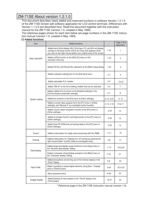
<strong>ZM</strong>-<strong>71SE</strong> <strong>About</strong> <strong>version</strong> <strong>1.2.1.0</strong><br />
This document describes newly added and improved functions in software Version <strong>1.2.1.0</strong><br />
of the <strong>ZM</strong>-<strong>71SE</strong> Screen edit software application for LCD control terminals. Differences with<br />
Version 1.1.0.0 are described here. Read this document together with the instruction<br />
manual for the <strong>ZM</strong>-<strong>71SE</strong> (<strong>version</strong> 1.0, created in May 1999).<br />
The reference pages shown for each item below are page numbers in the <strong>ZM</strong>-<strong>71SE</strong> instruction<br />
manual (<strong>version</strong> 1.0, created in May 1999).<br />
[1] Added functions<br />
Page in this<br />
Item<br />
Added functions<br />
* document<br />
Added items [Grid display (W)], [Grid type (Y)], and [Do not display<br />
overlap on the base screen (H)] to the menu that appears when<br />
you click on the right mouse button over a blank area of the screen.<br />
1-16<br />
1<br />
Basic operation<br />
Added a [Flip] function to the [Edit (E)] menu on the<br />
character menu bar.<br />
1-19<br />
2<br />
Added File No. and Record No. selections to the [Multi Copy] dialog. 1-20 3<br />
Added a [System setting] item to the [Edit item] menu. 2-1<br />
4<br />
Added selectable PLC models. 2-2 5 to 6<br />
Added "<strong>ZM</strong>-43" to the list of editing models that can be selected. 2-3<br />
Added a [Multi-link 2] choice to the [Detailed settings] in the<br />
[Communication parameter settings]. 2-7<br />
7<br />
8<br />
System setting<br />
Added the contents of the [P3] menu to [Other settings]. 2-13, 2-23<br />
Added a screen data capacity list to the [P1] menu in [Other<br />
settings], and "Manual 2" as a backlight control function.<br />
9, 12<br />
2-14, 2-16 10 to 11<br />
Added a touch switch emulation function to the [P2] menu in<br />
[Other settings].<br />
Added an [Output the bit in printing] function to the [P1] menu in<br />
[Other settings].<br />
Added [Use FP-ROM area as backup data] to the [P3] menu in<br />
[Other settings].<br />
2-20 13<br />
2-20 13<br />
2-23 14<br />
Screen Added a description for single cycle processing with the <strong>ZM</strong>80. 3-11<br />
16<br />
Overlap<br />
Added a description for "Display/Turn off overlap by pressing the<br />
right mouse button" to [Edit inside an overlapped area].<br />
4-8<br />
17<br />
Data display<br />
Added range and display range functions to the [Type] menu in<br />
the "Numeric data display" dialog.<br />
Added a character string display example to the [Main] menu in<br />
the "Character display" dialog.<br />
7-14 19 to 20<br />
7-16<br />
21<br />
Added precautions concerning use of the reverse display in the<br />
"Entry" dialog.<br />
9-8<br />
22<br />
Input mode<br />
Made it possible to create digital switches using [Num. Display]<br />
parts or [Switch] parts.<br />
9-34 22 to 23<br />
<strong>About</strong> password entry. 9-38<br />
23<br />
Grapgh display<br />
Added [Setting 3] menu details to the "Trend" dialog in the<br />
[Trend graph].<br />
10-27<br />
24<br />
* Reference page in the <strong>ZM</strong>-<strong>71SE</strong> instruction manual (<strong>version</strong> 1.0).
Item Added functions *<br />
Graphic display<br />
Added a description for the display area parts in the graphic<br />
relay mode.<br />
Added precautions for the graphic relay mode in the [Screen edit]<br />
function.<br />
11-14<br />
11-28<br />
Added an "Alarm display" choice to the sampling mode types. 12-1, 12-2<br />
Page in this<br />
document<br />
26<br />
27<br />
28<br />
Added a description for adding a start bit and expanded the<br />
number of words sampled in the buffer area setting dialog.<br />
12-4 29<br />
Added descriptions for "S: Normal operation bit" and "U: Sample<br />
operation bit" to the sample control memory in the buffer area<br />
setting dialog.<br />
12-6<br />
31<br />
Sampling mode<br />
Added a [Setting 3] menu to the [Trend sampling] dialog. 12-13<br />
32<br />
Added a description of real time printing to the [Bit sampling] dialog.<br />
Added descriptions of operating environment, setting procedures,<br />
setting the buffer area, setting the display mode and internal<br />
memory<br />
12-43<br />
12-24,<br />
12-50<br />
32 to 33<br />
30,<br />
34 to 42<br />
Added a time display item (<strong>ZM</strong>80 function). 43<br />
Added an [interval timer] and [event timer macro] to the macro<br />
start function.<br />
14-1<br />
44<br />
Macro<br />
Macro command table 14-2 45<br />
Added descriptions of precautions concerning the use of floating<br />
14-12 to 13,<br />
point decimal operations, reading the user log FA-M3, Ethernet,<br />
45 to 50<br />
14-20,<br />
SET-RGB and SET-BKLT in system call details and the extension<br />
14-23 to 14-24<br />
code for indirect memory assignment.<br />
Extended the SYS command and the macro transfer size for the<br />
macro command.<br />
14-13 48<br />
Added a description for the event timer macro<br />
Added a description of macro block editing.<br />
14-24<br />
14-25<br />
51<br />
52<br />
Added an extended memory setting (SRAM memory) (<strong>ZM</strong>80<br />
function).<br />
52 to 60<br />
Use 3D parts (<strong>ZM</strong>80 function) 61 to 63<br />
Internal memory<br />
Added details to the system memory table list. 15-2 to 15-8<br />
Added descriptions of addresses $s76/77, $s100/101, $s104/105,<br />
$s106/107, $s436 to 458, $s460 to 462, $s464 to 466, $s514 to<br />
619, and $s730 to 760, in the system memory<br />
15-11 to<br />
15-12<br />
64 to 71<br />
72 to 73<br />
Calender Added a description of [Time display setting]. 16-7<br />
74 to 78<br />
Added a functional description of the [Convert To Rich Text Format]<br />
item on the [Tool Function] list in the [Tool outline].<br />
23-1<br />
79<br />
Tools<br />
Added a description of "F for each function" to the Display Type<br />
Item List in Tool Function 2.<br />
Improved the function of the Bitmap Paste operation in Tool<br />
Function 8.<br />
Added Operation Method 5 to Tool Function 15.<br />
23-5<br />
80<br />
23-14 81<br />
23-25 82<br />
Added a Convert To Rich Text Format option in Tool Function 16. 23-26<br />
Transfer PLC type and I/F driver name 27-16<br />
83<br />
85 to 86<br />
Error table<br />
Added details and methods for checking error Nos. 72, 120, 121,<br />
130 to 134, 140 to 147, 202, and 203.<br />
29-10<br />
89 to 90<br />
* Reference page in the <strong>ZM</strong>-<strong>71SE</strong> instruction manual (<strong>version</strong> 1.0).
[2] Changed functions<br />
Item<br />
Changed functions<br />
*<br />
Page in this<br />
document<br />
System setting<br />
Data capacity available list on the [P2] menu.<br />
2-18<br />
11<br />
Lamp<br />
Arranged character string position for the [Character] menu lamp<br />
in the [Lamp] dialog.<br />
6-5<br />
18<br />
Macro<br />
Trend sampling in the command description. 14-12<br />
Provided details of the STA_TIME/CHK_TIME system call. 14-15<br />
46<br />
49<br />
File exchange Added Screen Data File Capacity to the file exchange details. 26-3<br />
84<br />
Error list<br />
Changed the display details. 29-3 87 to 88<br />
SYSTEM ERROR (<strong>ZM</strong>80)/Display unit error (<strong>ZM</strong>70) 29-12<br />
91<br />
* Reference page in the <strong>ZM</strong>-<strong>71SE</strong> instruction manual (<strong>version</strong> 1.0).
Chapter 1: Basic operation<br />
[1] Right-clicking menu (corresponds to page 1-16)<br />
When no parts are selected<br />
Right-clicking calls the following menu.<br />
1 [Undo]/[Redo]<br />
Same as [Undo]/[Redo] in the [Edit] menu.<br />
2 [ON Grid]<br />
When this command is clicked once, this menu item is checked. It<br />
means “on-grid editing.” When this menu item is clicked again, “ongrid<br />
editing” is canceled.<br />
3 [Grid Display]<br />
When this command is clicked once, this menu item is checked. It<br />
means “grid displayed.” When this menu item is clicked again, the<br />
grids disappear.<br />
4[Grid Type]<br />
Selects the grid type from [1-Byte], [Switch], [Mode], [Free].<br />
<br />
<br />
5 [Hide overlaps with Base checked]<br />
When this command is clicked once, this menu item is checked.<br />
When placing a normal overlap on a screen, editing on an overlap is<br />
possible by chaning editing layer from [Base] to [Overlap] in the rightclicked<br />
menu. Then, when changing editing layer from [Overlap] to<br />
[Base], the overlap disappears at the same time. Also, when retrying<br />
the layer changing, the overlap appears on a screen.<br />
Additional items<br />
6 [On-line Editing]<br />
This command is valid while Control Terminal is connected to a<br />
personal computer by a screen data transferring cable. When this<br />
command is clicked, the check mark appears. It means on-line<br />
editing. The command [On-line RUN] becomes valid.<br />
Clicking [On-line Editing] deletes its check mark. On-line editing is<br />
canceled.<br />
For more information on on-line editing, refer to Chapter 27, “Data<br />
Transference.”<br />
7 [On-line RUN]<br />
===This command becomes valid in on-line editing. When it is clicked,<br />
only the screen data which has not been transferred yet is transferred<br />
to Control Terminal.
[2] Menu Bar<br />
[Edit] Menu<br />
Changed the settings of grouped items (corresponds to page 1-19)<br />
In the original <strong>version</strong>, when you wanted to change the attribute of an item that was grouped,<br />
you had to select it from the item list or undo the grouping. In this <strong>version</strong>, it is possible<br />
change the attribute by double clicking on the item.<br />
Even if an item is included in a group, place the mouse cursor on the item and double<br />
click. A dialog will be displayed for reviewing and changing the item’s properties.<br />
The package setting function that was displayed when you double-clicked on a grouped item<br />
or an area specified in numeric display with the previous <strong>version</strong> can be displayed by clicking<br />
on the [Detail, Attribute Change] icon.<br />
[Flip] (corresponds to page 1-23)<br />
<br />
<br />
The following graphics can be turned over oppositely to the<br />
specified axis.<br />
<br />
Line, continuous line, box, parallelogram, polygon, circle,<br />
arc, sector, ellipse, elliptical arc, paint (including frame),<br />
scale<br />
<br />
Select the desired graphic. Click the [Flip] icon. The following<br />
[Flip] dialog is displayed.<br />
[Direction](Vertical/Horizontal)<br />
Select the axis to turn over the graphics.<br />
[Position](Left/Right/Up/Down/Center)<br />
Select the position of the graphic when turning over the<br />
graphic oppositely to the selected [Direction].<br />
[Copy]<br />
When the check box is turned on (checked), the graphic<br />
is copied at the reflected position with the original one<br />
remained.<br />
When clicking [OK], the [Flip] function is executed.
[Multi Copy] (corresponds to page 1-20 to 1-21)<br />
In the first <strong>version</strong>, when you specified a memory card<br />
memory address and wanted to copy from several<br />
addresses, the only way other addresses could be<br />
selected was by incrementing or not incrementing.<br />
In this <strong>version</strong>, you can select the file number and record<br />
number for incrementing (+1).<br />
<br />
Additional items
Setting items<br />
Additional<br />
items<br />
[1] System Setting Items (corresponds to page 2-1)<br />
Open a new or existing file and under [System Setting] of the [Edit] menu, there are various<br />
setting items. Refer to the respective sections for more information on the contents of these<br />
menu items.<br />
System Setting<br />
*1 For more<br />
information<br />
about Network<br />
Table, refer to<br />
"<strong>ZM</strong>-80NU<br />
Network Module<br />
Instruction<br />
Manual”.<br />
*2 For more<br />
information, refer<br />
to the<br />
"Temperature<br />
Control Network"<br />
manual.<br />
*3 For more<br />
information, refer<br />
to the "<strong>ZM</strong>-LINK"<br />
manual.<br />
Others<br />
Instruction Manual P2-13<br />
P1<br />
P2<br />
P3<br />
Event Timer Macro<br />
Chapter 14, Macro<br />
Time Display Format<br />
Chapter 16, Calendar<br />
(Network Table)<br />
*1<br />
Temp. Control Comm. Setting *2<br />
(Temp. Control Network Table) *2<br />
<strong>ZM</strong>-Link Setting<br />
*3<br />
(Station Number Table Setting) *3<br />
SRAM Cassette Setting<br />
Memory Expansion, Printer, Output bit in printing<br />
Print Direction, Reversed Image<br />
Backlight, Global Macro Memory<br />
Buzzer, (RUN/BZ port)<br />
Display Language, Font<br />
System Switch Prohibited<br />
Mode Switch Prohibited<br />
Change-over Time, Modular Jack 1/2<br />
DIO Input/Output Mem.<br />
Video Select<br />
Overlap Coordinates<br />
Blink, Touch Switch<br />
Transfer comments.<br />
Memory Capacity +2M<br />
Use Internal Flash ROM as Back-up Area.
[2] PLC Models (corresponds to page 2-2)<br />
PLC Models<br />
The 17 models with @ mark are added as follows. The <strong>ZM</strong> Series is compatible with 25 PLC<br />
manufacturers. The PLC models with “*” mark cannot be selected in <strong>ZM</strong>70.<br />
[Model]<br />
[Calender]<br />
@*Sharp : JW series<br />
Provided<br />
Sharp : JW100/70H COM port Provided<br />
Sharp : JW20 COM port<br />
Provided<br />
@ Sharp : PG port<br />
Provided<br />
@*Sharp : JW(FL-net)<br />
Provided<br />
@*Sharp : JW(Ethernet)<br />
Provided<br />
MITSUBISHI : AnA/N/U Series<br />
Provided<br />
MITSUBISHI : QnA Series<br />
Provided<br />
MITSUBISHI : QnH(Q) Series<br />
Provided<br />
MITSUBISHI : ACPU port<br />
Provided<br />
MITSUBISHI : FX Series<br />
Depends on the model<br />
@*MITSUBISHI : Net10<br />
Provided<br />
MITSUBISHI : A Link + Net10<br />
Provided<br />
MITSUBISHI : QnACPU port<br />
Provided<br />
@*MITSUBISHI : QnHCPU port (A) Provided<br />
@*MITSUBISHI : QnHCPU port (Q) Provided<br />
*MITSUBISHI : FX Series (A prt) Provided<br />
@*MITSUBISHI : FX2N Series<br />
Provided<br />
@*MITSUBISHI : FX1S Series<br />
Provided<br />
MITSUBISHI : QnA Series(Ethernet) Provided<br />
MITSUBISHI : QnH(Q) (Ethernet) Provided<br />
OMRON : SYSMAC C<br />
Depends on the model<br />
OMRON : SYSMAC CV<br />
Provided<br />
*OMRON : SYSMAC CS1<br />
Provided<br />
@*OMRON : SYSMAC CS1 DNA<br />
Provided<br />
HITACHI : HIDIC- H<br />
Provided<br />
HITACHI : HIDIC- S10/2 <br />
Not provided<br />
HITACHI : HIDIC- S10/ABS<br />
Not provided<br />
MATSUSHITA : MEWNET<br />
Depends on the model<br />
YOKOGAWA : FA500<br />
Provided<br />
YOKOGAWA : FA-M3<br />
Provided<br />
YOKOGAWA : FA- M3/FA- M3R(Ethernet) Provided<br />
@*YOKOGAWA : FA- M3R<br />
Provided<br />
YASKAWA: Memobus<br />
Depends on the model<br />
@*YASKAWA: CP9200SH/MP900<br />
Not provided<br />
TOYOPUC<br />
Provided<br />
*FUJI : MICREX- F Series<br />
Provided<br />
FUJI : MICREX- F Series <strong>ZM</strong>70 Compatible<br />
FUJI : FFLEX- PC Series<br />
Provided<br />
FUJI : FLEX- PC CPU<br />
Provided<br />
FUJI : FLEX- PC COM<br />
Provided<br />
FUJI : FLEX- PC(T)<br />
Provided<br />
FUJI : FLEX- PC CPU(T)<br />
Provided
[Model]<br />
KOYO : SU/SG<br />
KOYO : SR- T<br />
*KOYO : SR- T(K prt)<br />
A.B : PLC- 5<br />
A.B :SLC500<br />
A.B :Micro Logix 1000<br />
GE Fanuc :90 Series<br />
GE Fanuc :90 Series(SNP- X)<br />
TOSHIBA : T Series<br />
*TOSHIBA MACHINE : TC200<br />
*SEIMENS : S5<br />
*SEIMENS : S7<br />
@*SEIMENS : S7 PROFIBUS- DP<br />
SEIMENS : S5 (compatible with <strong>ZM</strong>70)<br />
SEIMENS : TI500/505<br />
SEIMENS : TI500/505 (compatible with <strong>ZM</strong>70)<br />
SEIMENS : S7- 200 PPI<br />
*SEIMENS : S5 PG port<br />
@*SEIMENS : S7- 300MPI(HMI ADP)<br />
@*SEIMENS : S7- 300MPI(PC ADP)<br />
SHINKO : SELMART<br />
SAMSUNG : SPC Series<br />
*SAMSUNG : N_plus<br />
*SAMSUNG : SECNET<br />
KEYENCE : KZ Series<br />
KEYENCE : KZ- A500 CPU port<br />
*KEYENCE : KV Series<br />
@*KEYENCE : KZ24/300 Series CPU<br />
@*KEYENCE : KV10/24 Series CPU<br />
LG : MASTER- K10/60/200<br />
LG : MASTER- K500/1000<br />
@*LG : GMKX00S<br />
FANUC : Power Mate<br />
FATEC AUTOMATION : FACON FB Series<br />
IDEC : MICRO3<br />
*MODICON : Modbus RTU<br />
*YAMATAKE :MX Series<br />
*TAIAN : TP02<br />
Universal Serial<br />
General-purpose FL-Net<br />
[Calender]<br />
Provided<br />
Provided<br />
Not provided<br />
Not provided<br />
Provided<br />
Not provided<br />
Not provided<br />
Not provided<br />
Provided<br />
Provided<br />
Not provided<br />
Not provided<br />
Not provided<br />
Not provided<br />
Provided<br />
Provided<br />
Provided<br />
Not provided<br />
Provided<br />
Provided<br />
Provided<br />
Not provided<br />
Provided<br />
Depends on the model<br />
Not provided<br />
Provided<br />
Not provided<br />
Not provided<br />
Not provided<br />
Not provided<br />
Not provided<br />
Not provided<br />
Not provided<br />
Provided<br />
Provided<br />
Depends on the model<br />
Provided<br />
Provided
[3] Edit Model Selection (corresponds to page 2-3)<br />
Select the <strong>ZM</strong> Series model to edit from the diagram below.<br />
Edit model selection<br />
<strong>ZM</strong>80 Series<br />
<strong>ZM</strong>82 (800600 12.1 inch)<br />
<strong>ZM</strong>-72S (800600 10.4 inch)<br />
<strong>ZM</strong>72 (640480 10.4 inch)<br />
<strong>ZM</strong>52 (640480 7.7 inch)<br />
<strong>ZM</strong>42 (320240 5.7 inch)<br />
<strong>ZM</strong>43 (320240 5.7 inch)<br />
<br />
<strong>ZM</strong>70 Series<br />
<strong>ZM</strong>70 (640480) (16 colors)<br />
Reserved (640480) (8 colors)<br />
<strong>ZM</strong>70 (640480) (Monochrome)<br />
<strong>ZM</strong>41 (320240) (16 colors)<br />
<strong>ZM</strong>41 (320240) (Monochrome)<br />
<strong>About</strong> the <strong>ZM</strong>43<br />
Basically the details are the same as for the <strong>ZM</strong>42. However the following items are different.<br />
1. A special <strong>ZM</strong>-80NU network module for the <strong>ZM</strong>42 can be used.<br />
Therefore, the <strong>ZM</strong>43 can easily use access Ethernet and FL-net networks.<br />
2. A <strong>ZM</strong>-43EM expansion memory can be used.<br />
3. The life of the backlight is approximately 50,000 hours.<br />
<br />
When the “ <strong>ZM</strong>-43EM expansion memory “ is installed on the <strong>ZM</strong>43.<br />
Select [4M (Memory expansion 1)] or [4M (memory expansion 2)] in the [Extension memory]<br />
item on [Other Settings/P1] in [Other settings (O)] for [System Settings (A)].<br />
The screen data capacities in each language are shown in the table below.<br />
Unit : kbyte<br />
Standard Memory expansion 1*1 Memory expansion 2*2<br />
Japanese 1,216 5,248 3,712<br />
Japanese 32*3 768 4,800 3,264<br />
English (Western Europe) 1,408 5,440 3,904<br />
Chinese 1,280 5,312 3,776<br />
Chinese (Simplified) 1,216 5,248 3,712<br />
Korean 1,344 5,376 3,840<br />
*1 Capacity of the display data when the memory is extended and DIP SW No.1 is set to OFF<br />
(standard).<br />
*2 Capacity of the display data when the memory is extended and DIP SW No.1 is set to ON.
un<br />
<br />
<br />
<br />
<br />
<br />
<br />
<br />
<br />
<br />
<br />
<br />
<br />
<br />
<br />
<br />
<br />
<br />
[4] Communication Parameter<br />
[Detail] Tab Window<br />
Note<br />
[Multi-Link2] can be used<br />
only in <strong>ZM</strong>80. It is not<br />
available in <strong>ZM</strong>70.<br />
In case of [Multi-Link2] (n : 1) (corresponds to page 2-7)<br />
When connecting multiple <strong>ZM</strong>80s (up to 4) to one PLC (n : 1), choose [Multi-Link2]<br />
which can support faster communication than [Multi-Link]. The communications via RS-<br />
232C, RS422 and RS485 are available.<br />
*This connection cannot be used when using the communication interface module (e.g.<br />
JPCN-1, CC-Link, etc.).<br />
*If <strong>ZM</strong>42 is the master station (Local Port: 1), all the slave station (Local Port: 2 and after)<br />
must be <strong>ZM</strong>42.<br />
<strong>ZM</strong>80 master <strong>ZM</strong>80 <strong>ZM</strong>80 <strong>ZM</strong>80<br />
RS-232C<br />
RS-422<br />
RS-485<br />
RS-485<br />
PLC<br />
[Setting...] button<br />
When [Multi-Link2] is selected, the next option [Setting...] must also be set up.<br />
Clicking this button brings up the [Multi-Link2] dialog as shown below.<br />
[Local Port] (1 to 4)<br />
Specify the station number of <strong>ZM</strong>80 Series. If one station number is used twice<br />
or more for different <strong>ZM</strong>80s being connected to one PLC, the entire system<br />
does not work properly. Be sure to use one station number to a single <strong>ZM</strong>80.<br />
*When selecting [2], [3] or [4] in this setting, [Baud Rate], [Signal Level], [Parity],<br />
[Trans. Mode], [Data Length], [Stop Bit], [Time-Out] and [Retrials] cannot be<br />
specified.<br />
[Send Delay Time] (unit: x 1 msec)<br />
This setting is available only when [Local Port] is [1]. The setting is the same as<br />
in case of [Multi-Link 1].<br />
[Total] (1 - 4)<br />
Specify the number of <strong>ZM</strong>s to be connected.<br />
[Retry Cycle] (x 10)<br />
The setting is the same as in case of [Multi-Link 1].<br />
[Baud Rate of Multi-Link] (4800, 9600, 19200, 38400, 57600, 115kbps)<br />
The communication speed between <strong>ZM</strong>80s can be specified in this item.<br />
The setting must be the same as other <strong>ZM</strong>80s on the same communication line.<br />
Note that the maximum of baud rate when using <strong>ZM</strong>42 is 57600 bps.<br />
Communication Start time (<strong>ZM</strong>80 model only) (correspondense to page 2-9)<br />
Set a communication delay time in seconds for <strong>ZM</strong>80 to avoid a delay in processing<br />
on the PLC (or controller) when <strong>ZM</strong>80 and a connected PLC (or controller) are<br />
turned on at the same time.<br />
How to assign<br />
Select a delay time from the [Start time] item on the [Communication parameter/<br />
detailed settings] menu in the [Communication parameter settings (T)].
[5] Other Settings (corresponds to page 2-13)<br />
This section describes settings related to the <strong>ZM</strong> Series hardware.<br />
Others<br />
Additional<br />
items<br />
P3<br />
Video Selected<br />
NTSC<br />
PAL<br />
Overlap Coordinates Line/Column<br />
Dot<br />
Blink OFF time/ON time<br />
Touch Switch<br />
Analog Siwtch<br />
Transfer comments Matrix Switch<br />
Memory capacity +2M<br />
Use Internal Flash ROM as Back-up Area
N<br />
NC<br />
L<br />
100-<br />
240VAC<br />
CN2<br />
MJ2<br />
MJ1<br />
[P1] Tab Window<br />
2 Memory expansion 2 (corresponds to page 2-14)<br />
When you turn DIP SW No. 1 (left) located on the rear of the <strong>ZM</strong> to ON, fonts,<br />
Expansion memory<br />
: <strong>ZM</strong>-2EM<br />
interface drivers, and screen data other than <strong>ZM</strong> programs can be written.<br />
The amount of screen data will be as shown<br />
When using the expansion<br />
memory <strong>ZM</strong>-2EM type, select<br />
[2M (Memory Extension<br />
<strong>ZM</strong>80 body<br />
1 Remove the cover.<br />
below.To modify the screen data on a <strong>ZM</strong>80<br />
in a remote area (overseas, etc.), modification<br />
1/2] in [Expansion Memory].<br />
2 Mount the expansion memory.<br />
can easily be performed by entering the<br />
modified data into a memory cassette at one’s<br />
workplace, and then forwarding the memory<br />
cassette on to where the modification will take<br />
place.<br />
CN1<br />
CN1<br />
FROM0<br />
JP1<br />
FROM1<br />
V97-MEMC P02004<br />
3DIP SW No.1.<br />
ON<br />
DIP SW<br />
123456798<br />
Additional<br />
items<br />
<strong>ZM</strong>80<br />
Font<br />
Japanese<br />
Japanese 32<br />
English(Western Europe)<br />
Chinese<br />
Chinese (Simplified)<br />
Korean<br />
Standard<br />
1,179,648<br />
786,432<br />
1441,792<br />
1310,720<br />
1179,648<br />
1310,720<br />
*1<br />
Memory<br />
Extension 1 +2M<br />
3,260,416<br />
2,867,200<br />
3,522,560<br />
3,391,488<br />
3,260,416<br />
3,391,488<br />
*1<br />
Memory<br />
Extension 1 +4M<br />
5,357,568<br />
4,964,352<br />
5,619,712<br />
5,488,640<br />
5,357,568<br />
5,488,640<br />
*2<br />
Memory<br />
Extension 2 2M<br />
1,703,936<br />
1,179,648<br />
1,835,008<br />
1,703,936<br />
1,703,936<br />
1,835,008<br />
Unit : bytes<br />
*2<br />
Memory<br />
Extension 2 4M<br />
3,801,088<br />
3,276,800<br />
3,932,160<br />
3,801,088<br />
3,801,088<br />
3,932,160<br />
*1 Capacity of the display data when the memory is extended and DIP SW NO.1 is set to OFF (standard).<br />
*2 Capacity of the display data when the memory is extended and DIP SW NO.1 is set to ON.<br />
Standard Capacity<br />
The standard memory<br />
capacity is different<br />
according to the hardware<br />
<strong>version</strong> of <strong>ZM</strong>80. And, the<br />
memory capacity can be<br />
defined by [P3] menu<br />
(page 2-23) of the [Others]<br />
dialog in addition to the<br />
setting of [Memory<br />
Expansion] in [P1] menu.<br />
If the memory capacity is<br />
different from the list<br />
shown right, contact to the<br />
technical service of<br />
Control Terminal.<br />
<strong>ZM</strong>80<br />
Font<br />
Japanese<br />
Japanese 32<br />
English(Western Europe)<br />
Chinese<br />
Chinese (Simplified)<br />
Korean<br />
Standard<br />
3,200<br />
2,816<br />
3,456<br />
3,328<br />
3,200<br />
3,328<br />
*1<br />
*2<br />
Memory Memory<br />
Extension 1 +4M Extension 2 +4M<br />
7,232<br />
6,848<br />
7,488<br />
7,360<br />
7,232<br />
7,360<br />
Unit : KB<br />
3,712<br />
3,200<br />
3,840<br />
3,712<br />
3,712<br />
3,840<br />
*1 Capacity of the display data when the memory is extended and DIP SW NO.1<br />
is set to OFF (standard).<br />
*2 Capacity of the display data when the memory is extended and DIP SW NO.1<br />
is set to ON.<br />
Additional<br />
items
[Manual 2] (compatible mode for <strong>ZM</strong>80) (corresponds to page 2-17)<br />
Added the [Manual 2] item to the backlight control function.<br />
[Manual] operation allows you to turn ON the backlight by touching the screen from the<br />
system program files ver. 1.2.0.0. Therefore, this function is not compatible with the <strong>ZM</strong>70.<br />
In order to be compatible with the <strong>ZM</strong>70, the [Manual 2] function has been added, starting<br />
with this <strong>version</strong>. Select this item for compatibility with the <strong>ZM</strong>70.<br />
How to assign<br />
Select [Others], [Others/P1], and [Start Time], in that order.<br />
When [Manual2] is chosen, the backlight can be turned ON/OFF by pressing the [SYSTEM]<br />
<br />
+ [F · 5] keys on the <strong>ZM</strong>80 series or setting/resetting (edge) bit 11 of the Read Area + "1."<br />
*The switches on the screen are valid even while the backlight is OFF.<br />
The <strong>ZM</strong>70 and the <strong>ZM</strong>80 differ in the following points.<br />
The [SYSTEM] + [F · 5] keys are valid for the <strong>ZM</strong>70 even while bit 11 of the Read Area “n+1”<br />
is set (ON). These keys are not valid for the <strong>ZM</strong>80 in such a state. Reset (OFF) bit 11 of the<br />
Read Area “n+1.”<br />
(corresponds to page 2-18)<br />
Font<br />
Select one of the following five languages for transferring screen data files. The screen data<br />
capacity for the <strong>ZM</strong> series is limited to 1,109,904 bytes irrespective of language selection.<br />
For the <strong>ZM</strong>80, Japanese 32 is also available, which is a 32-dot font. If the enlargement<br />
factor is an even number, the 32-dot font is used to create a smooth typeface.<br />
<strong>ZM</strong>80<br />
Japanese<br />
Japanese 32<br />
English/Western Europe<br />
Chinese<br />
Chinese (simplified)<br />
Korean<br />
Capacity<br />
3,200<br />
2,816<br />
3,456<br />
3,328<br />
3,200<br />
3,328<br />
(Unit : KB)<br />
<strong>ZM</strong>70<br />
Japanese<br />
English<br />
Chinese<br />
Chinese (simplified)<br />
Korean<br />
Change
[P3] Tab Window (corresponds to 2-23)<br />
This paragraph is explained about additional each menu in this book page 9-[5] Others.<br />
Blink<br />
”OFF Time” (*100msec) / “ON Time” (*100msec)<br />
When the value is “0” , the conventional blink time (about 0.5 seconds interval) comes.<br />
* In case of <strong>ZM</strong>70, you can not set.<br />
Touch Switch (Analog Switch / Matrix Switch)<br />
When using the <strong>ZM</strong>80 matrix type, select [Matrix Switch].<br />
The types for matrix switch are as follows;<br />
Model <strong>ZM</strong>82 <strong>ZM</strong>72 <strong>ZM</strong>43<br />
No. of switches(WH) 5030 4024 2012<br />
(Order product)<br />
Transfer comments (<strong>ZM</strong>80 only)<br />
When checking this setting, the comments in each editing item can be transferred with the<br />
screen data to a <strong>ZM</strong>80.<br />
* The capacity of the comments will be added to the total memory capacity of the screen<br />
data.<br />
Memory Capacity +2M<br />
The default setting is [checked]. If the used <strong>ZM</strong>80 (except for <strong>ZM</strong>42) has the memory<br />
capacity less than 2M, uncheck the setting.<br />
When unchecking the setting, decrease the total memory capacity in [Memory Use] of [Tool].<br />
Use Internal Flash ROM as Back-up Area<br />
See page 14 in detail.<br />
Use ladder monitor<br />
- See the <strong>ZM</strong>-42/52/72/82 User’s Manual Ladder Monitor <strong>version</strong> in detail.<br />
- When you use ladder monitor function, check the mark in this item. If check mark was<br />
done, <strong>ZM</strong> series transfer ladder monitor program (expansion program)with screen data<br />
at the same time.
Emulating a touch screen (corresponds to page 2-20)<br />
This function can be selected when the <strong>ZM</strong>72TR (a special order production model) is used as<br />
an analog RGB input. (An analog touch panel).<br />
Using this function, you can control the Windows operating system running on a personal computer<br />
(when displayed on the <strong>ZM</strong>72TR) by touching the screen instead of using a mouse.<br />
For details about the touch panel driver made by Gunze (for use on a personal computer),<br />
contact our sales division.<br />
How to select the touch screen function<br />
Select [System settings (A)], [Other settings (O)], [Other settings/P2], [Modular jack 1] or<br />
[Modular jack 2] and then [Touch screen], in that order.<br />
Output the bit in printing (<strong>ZM</strong>80 function) (corresponds to page 2-15)<br />
Print data sending bit (0: end (waiting), 1: print data sending)<br />
Bit No. 10 of Write Area n+1<br />
Write Area n+1<br />
MSB<br />
15 14 13 12 11 10 09 08 07 06 05 04 03 02 01 00<br />
0 0 0 0 0<br />
LSB<br />
Print data sending<br />
Bit No. 0 of Internal Memory $s16<br />
$s16<br />
MSB<br />
LSB<br />
15 14 13 12 11 10 09 08 07 06 05 04 03 02 01 00<br />
0 0 0 0 0 0 0 0 0 0 0 0 0 0<br />
Print data sending<br />
When <strong>ZM</strong>80 receives the printing command of hard copy, sanple print or data sheet print, it<br />
will start sending the print data to a printer. The sending condition will be output to the above<br />
area.<br />
The information [0 to 1] is written at the timing of print data sending start, and [1 to 0] is<br />
written at the timing of completion of sending. However, printing may be executed without<br />
writing print data sending information though <strong>ZM</strong>80 received the printing command, because<br />
of a little print data.<br />
To make the printing information written to the memory area anytime when <strong>ZM</strong>80 receive the<br />
printing command, check [Output the bit in printing.]<br />
How to select output during printing<br />
Click on the [Output bit during printing] box in the [Other settings/P1] submenu on [Other<br />
settings (O)] in the [System settings (A)]. (This box is checked as the default when you create<br />
a new file.)
Use FP-ROM area as backup data(<strong>ZM</strong>80 function) (corresponds to page 2-23)<br />
<br />
The remaining area in the screen data FP-ROM (flash memory) can be used for PLC<br />
memory, internal memory, or memory card for data backup. A maximum of 16k words is<br />
usable as the data backup area.<br />
* The capacity of the display data will be reduced by 128kbytes.<br />
Setting procedure<br />
Choose [Others] from [System Setting]. The [Other Settings] dialog is displayed. In the<br />
[P3] tab window, check [Use Internal Flash ROM as Back-up Area].<br />
Data backup procedure<br />
Data can be written to the FP-ROM at one time by macro command [FROM_WR].<br />
For reading backup data from the FP-ROM, use the macro command [FROM_RD].<br />
[FROM_WR]<br />
The number of words (maximum 16K words) specified for F1 are written from the F0<br />
memory to the FP-ROM.<br />
Usable devices<br />
Internal memory PLC memory Constant Memory card Indirect set Word<br />
F0 <br />
F1 <br />
FROM_WR : Writing to FROM FROM_WR F0<br />
F1<br />
[FROM_RD]<br />
The number of words (maximum 16K words) specified for F1 are read from the FP-ROM<br />
to the F0 memory.<br />
Usable devices<br />
Internal memory PLC memory Constant Memory card Indirect set Word<br />
F0 <br />
F1 <br />
FROM_RD : Read to FROM FROM_RD F0 F1<br />
1. It will be possible to write to the FP-ROM one hundred thousand times.<br />
(One execution of [FROM_WR] is counted as one time, irrespective of the<br />
specified number of words.)<br />
It is recommended that backup data be read at power-on and be written<br />
before power-down.<br />
2. <strong>About</strong> 3 to 5 seconds will be necessary for writing to the FP-ROM.<br />
3.Do not execute [FROM_WR] or [FROM_RD] in every cycle using cycle<br />
macro, etc.<br />
4.When reading the words by [FROM_RD] more than the words written by<br />
[FROM_WR], the [FROM_RD] is not executed.<br />
The value [-1] is written to $s728 (refer to the next section.)<br />
<strong>About</strong> system memory (s)<br />
The following system memory ($s) is related to the use of the FP-ROM as the data backup<br />
area.<br />
- Address s728<br />
A result by the execution of [FROM_WR] or [FROM_RD] is written to this address.<br />
[0]: Normal [-1]: Abnormal
Additional error number to be displayed on the <strong>ZM</strong>80<br />
The following new error number is provided for check error.<br />
Error number (see following table.)<br />
Check<br />
Data has some error.<br />
Data has some error.<br />
Error:155 ( 0 : )<br />
Error:155 ( 0 : )<br />
Error No.<br />
Item No.<br />
<strong>ZM</strong>80 <strong>ZM</strong>70 Error No. Contents Remedies<br />
155<br />
While [Use Internal Flash ROM as<br />
Back-up Area] is checked, no “default.<br />
dtm” file is sent.<br />
<br />
<br />
<br />
<br />
<br />
<br />
1)The “default.dtm” file is contained in the “<strong>ZM</strong>71S\Tpa” folder.
Chapter 3 : Screens<br />
(corresponds to page 3-11)<br />
Processing One Cycle on <strong>ZM</strong>80<br />
One cycle processing is complicated. Refer to the following figure.<br />
Reading from<br />
the read area<br />
Reading from<br />
the read area<br />
Reading from<br />
the read area<br />
Reading<br />
high-speed<br />
data block 1<br />
Reading<br />
high-speed<br />
data block 1<br />
Reading<br />
high-speed<br />
data block 1<br />
Reading<br />
high-speed<br />
data block m<br />
Reading<br />
high-speed<br />
data block m<br />
Reading<br />
high-speed<br />
data block m<br />
Cycle start<br />
Reading<br />
low-speed<br />
data block 1<br />
Reading<br />
low-speed<br />
data block 2<br />
Reading<br />
low-speed<br />
data block m<br />
n = 0<br />
1 cycle 1 cycle 1 cycle<br />
[Event Timer] No. n<br />
exists ?<br />
YES<br />
NO<br />
[Event Timer] No. n<br />
time-up ?<br />
NO<br />
YES<br />
[Event Timer] No. n<br />
executed<br />
Process Item 0<br />
Process Item 1<br />
n = n + 1<br />
n < 8<br />
NO<br />
YES<br />
Process Item 2<br />
Process Item 3<br />
1. Execute PLC Memory transfer in Screen Setting.<br />
2. Transfer three words of Read Area to System<br />
Memory ($s460 ~).<br />
Cycle Macro executed<br />
* Write area does not exist because this<br />
address is processed at the another<br />
cycle.<br />
Read Area n (RCVDAT) processed<br />
Read Area n+1 (SCRN_COM) processed<br />
Process Item m<br />
Read Area n+2 (SCRN_No) processed<br />
Cycle end
Chpter 4 : Overlap<br />
[1] Normal Overlap (corresponds to page 4-7)<br />
Editing in Overlap<br />
2Menu bar “Display”<br />
2Go to [Display Environment Setting] under the [Display] menu on<br />
the menu bar and bring up the [Display Environment] dialog.<br />
From there, go to [Detailed Setting] and then to change the editing<br />
layer.<br />
* A layer change is performed when an overlap number is chosen.<br />
* When an overlap is selected for the editing layer, the modes placed<br />
on the selected overlap are indicated in the auxiliary tool box at the<br />
bottom left corner of the screen.<br />
When the editing layer is moved to the base screen, the modes on<br />
the base screen are indicated in the auxiliary tool box.<br />
Additional<br />
items<br />
Set Display/Non-Display by Right-Clicked Menu<br />
It is possible to decide display or non-display of normal overlaps on<br />
the screen by the right-clicked menu. When rilght-clicking overlaps ,<br />
the following menu is displayed (same menu as the [Display<br />
Environment] dialog).<br />
Check the [Hide overlaps with Base checked.]. When placing a<br />
normal overlap on a screen, editing on an overlap is possible by<br />
changing editing layer from [Base] to [Overlap] in the right-clicked<br />
menu. Then, when changing editig layer from [Overlap] to [Base], the<br />
overlap disappears at the same time. Also, when retrying the layer<br />
changing, the overlap appears on a screen.
Chpater 6 : Lamp<br />
[1] [Lamp] Dialog<br />
[Character] Tab Window<br />
Add the “Centering”, “Copy Characters” button (corresponds to page 6-6)<br />
[Centering]<br />
The text in a lamp will be center-aligned.<br />
[Copy Characters]<br />
By clicking the [Copy Characters] button, the text and the text property of the corresponding<br />
lamp are copied to all patterns (such as OFF, ON or P3).<br />
Lamp Text Alignment (correspondense to page 6-6)<br />
The text in a lamp will be center-aligned. If not, display the [Character] menu of the [Lamp]<br />
dialog, and click the [Centering] button.<br />
The text is center-aligned.<br />
If you want to make the text on the placed lamp center-aligned, click<br />
the lamp part (handles are shown), select [Align] from the [Edit] menu,<br />
and click [Switch/Lamp Centering].<br />
When two or more lines of text are set, clicking [Switch/Lamp Centering] brings up the [Pitch]<br />
dialog. Specify the desired pitch, and click [OK]. The lines of text are aligned. Clicking<br />
[Default] places the text in the default position.<br />
Change
Chapter 7 : Data Display<br />
[1] Numerical Data Display<br />
Numerical Data Display(corresponds to page 7-14)<br />
[Detail] Tab Window<br />
- Range and Display Range Functions<br />
This function can calculate and display the data read by PLC automatically according to the<br />
specified range. It can reduce the PLC programs for calculating the data of the temperature or<br />
the number of rotation, etc.<br />
Setting procedure<br />
Bring up the [Num. Display] dialog under a [Num. Data Display] part. Make a setting in the<br />
[Type] tab window.<br />
(Setting is also possible by choosing [Simple Data Display (Num.)].)<br />
[Specify Range]<br />
By checking this item, a value set for [Input Range] is converted according to the [Display<br />
Range] setting and displayed. A calculated value is round down to be displayed.<br />
[Input Range]<br />
Specify an input range.<br />
[Display Range]<br />
Specify a display range.<br />
Note that the correct value may not be displayed when the result of multiplying<br />
the value of [Memory] and [Display Range (Max.)] is greater than double-word<br />
data.<br />
Ex.) *Numerical data display<br />
In the case of [Input Range: 0 - 4000] and [Display Range: 0 - 100]:<br />
When the PLC memory D100 is set to “2000,” the <strong>ZM</strong> shows “50.”<br />
*Input mode<br />
In the case of [Input Rage: 0 - 4000] and [Display Range: 0 -100]:<br />
When “25” is keyed in, “1000” is written to D100.<br />
Range function may cause an error in calculation when it is used in Input<br />
mode. When the [Input Range] data is greater than the [Display Range]<br />
data, the input values is correct.<br />
Input Range > Display Range The input value is correct. Input Range < Display Range The input value is not correct.<br />
Input value (entered by keys)<br />
[Display Range]<br />
PLC<br />
[Input Range]<br />
Input value (V6)<br />
[Display Range]<br />
Input value (entered by keys)<br />
[Display Range]<br />
PLC<br />
[Input Range]<br />
Input value (V6)<br />
[Display Range]<br />
10000<br />
10000<br />
10000<br />
100<br />
2500<br />
100<br />
25<br />
25<br />
0 0<br />
0<br />
250<br />
0<br />
100<br />
200<br />
2 0 0
When setting in the [Detail] tab window of the [Num Display] dialog:<br />
[Alarm]<br />
The specified maximum and minimum values are compared with converted and displayed<br />
values.<br />
Ex.)<br />
In the case of [Input Range: 0 - 4000], [Display Range: 0 - 50], and [Max.: 40] and [Min.:<br />
10] for [Alarm]: An upper limit alarm is given when the PLC memory D100 is set to “3200,”<br />
and a lower alarm is given when it is set to “800.”<br />
[Use Operation]<br />
A correct result will not be given if a value becomes larger than double word halfway<br />
through operation.
[2] Character Display<br />
[Character Display] Dialog (corresponds to page 7-16)<br />
[Main] Tab Window<br />
[Division No.]<br />
The division number that is effective when the [Char. Display] icon is clicked is<br />
automatically entered.<br />
As many character display parts as possible can be placed as long as memory is available.<br />
It is possible to place these parts and other parts in the same division.<br />
If creating a character display part linked with another part, they must be placed in the<br />
same division. Whether the character display part should be linked with a part can be<br />
chosen by the [Display Function] option.<br />
[Memory] (PLC Memory, Internal Memory, Memory Card)<br />
Data contained in the specified memory area is displayed in characters on the screen.<br />
One-byte characters are processed as ANK codes, and two-byte characters are processed as<br />
Shift JIS codes (in the case of Japanese).<br />
One-byte character : 1/2 word (= 1 byte) ANK code<br />
Two-byte character : 1 word (= 2 bytes) Shift JIS code<br />
Ex.) Character display [Memory: D500], [Bytes: 6]<br />
When inputting 09000 : H3231, 09502 : H3433 and 09504 : H4241, the characters<br />
[1234AB] is displayed on <strong>ZM</strong>80.<br />
<br />
Additional<br />
items<br />
<br />
<br />
<br />
<br />
<br />
<br />
When inputting 09000: H3231, 09502: H0033 and 09504: H4241, the<br />
characters [123] is displayed on <strong>ZM</strong>80. Note that the characters after the null<br />
(00) code are not displayed when inputting null (00) code. When you want to<br />
display the space, input the space code (20).
Chapter 9 : Entry Mode<br />
[1] Direct Data Entry for Data Display Parts ( = [Type: Data Display])<br />
[Entry] Dialog Setting<br />
(corresponds to page 9-8)<br />
Note<br />
When [Enlarge Y]<br />
of the [Entry<br />
Target] data display<br />
is more than [4] (64<br />
dots), the [Reverse]<br />
is not displayed<br />
normally.<br />
[Reverse]<br />
This option determines whether or not to highlight the data display part (in reverse video)<br />
currently selected as the entry target. This is effective when [Data Display] or [Block] is<br />
chosen for [Type].<br />
Additional item<br />
[2] Digital Switch (For <strong>ZM</strong>80 only)(corresponds to page 9-34)<br />
Outline<br />
Creation of a digital switch is now easy with [Num. Data Display] and [Switch] parts. ([Simple<br />
Data Display (Num.)] and [Switch] parts are also valid for digital switch creation.)<br />
Bring up the [Num. Display] dialog under a [Num. Data Display] part, and open the [Detail] tab<br />
window. Checking [Alarm] makes the settings of maximum and minimum values available.<br />
[Use Operation] and [Specify Range] under a [Num. Data Display] part are also available.<br />
Without carry:<br />
Only the value of thespecified digit changes.<br />
<br />
[Example]<br />
Plus value with/without sign:<br />
Pressing the [+] key above the first digit<br />
changes “129” to “120.”<br />
Pressing the [-] key above the first digit<br />
changes “120” to “129.”<br />
Minus value with sign:<br />
Each time the [+] key above the first digit is<br />
pressed, the displayed value changes as “-<br />
008” --> “-009” --> “000” --> “001” --><br />
“002.”<br />
Change the sign using a switch ([Switch<br />
Function]: [Digital Switch Toggle Sign]).<br />
+<br />
1<br />
-<br />
+<br />
2<br />
-<br />
+<br />
0<br />
-<br />
Only the first-digit value<br />
changes in the order of “0,”<br />
“1,” “2,” “3,” ... “9,” “0,” and “1.”<br />
Only the first-digit value<br />
changes in the order of<br />
“0,” “9,” “8,” “7,” ... “1,” and “0.”<br />
With carry:<br />
Carries are generated.<br />
[Example]<br />
Plus value with/without sign:<br />
Pressing the [+] key changes “129” to “130.”<br />
Pressing the [-] key changes “120” to “119.”<br />
Minus value with sign:<br />
Pressing the [+] key changes “-129” to “-128.”<br />
Pressing the [-] key changes “-129” to “-130.”<br />
<br />
+<br />
1<br />
-<br />
Up<br />
+<br />
2<br />
-<br />
Down<br />
+<br />
0<br />
-
Digital Switch Setting<br />
[Num. Display] dialog setting<br />
[Division No.]<br />
Specify the division number used for the related switch.<br />
[Display Function]<br />
Choose [Digital Switch].<br />
[Move up/down the figure]<br />
Check this item when carry is necessary.<br />
[Switch] dialog setting<br />
[Division No.]<br />
Specify the division number used for the related numerical data display.<br />
[Switch Function]<br />
Choose [Digital Switch +] or [Digital Switch -] from the [Digital Switch] menu.<br />
Set [Target figure] to perform input.<br />
When changing the sign, choose [Digital Switch Toggle Sign].<br />
When multiple numerical data displays ([Display Function]: [Digital Switch]) with the<br />
same division number exist, the item placed first (first item in the item list) becomes the<br />
operation target.<br />
Supply of Custom Parts<br />
The custom parts (file name: Digital_SW_Z7F) containing registered digital switches are to be<br />
supplied by us.<br />
Usage<br />
1.Choose [Custom Part] from the [Tool] menu, and click [Open].<br />
Open the “Digital_SW.Z7F” file. Drag the desired digital switch to the screen edit window.<br />
2.While the digital switch is chosen, right-click it and choose [Change All].<br />
3.The [Change All] dialog is displayed. Check [Change All Division No.], and specify a<br />
division number not in use.<br />
4.When changing numerical data display memory, double-click the desired display. The<br />
[Num. Display] dialog is displayed.<br />
[3] Password Function (corresponds to page 9-38)<br />
It is easy to enter a password in the entry mode.<br />
[Display Function] and [Detail Setting] tab windows appear as added setting items on the<br />
character display parts tool bar.<br />
[Display Function] ([Main] tab window)<br />
Select [Password Entry]. This adds setting items to the [Detail] tab window.<br />
[Password 0 (to 3)] ([Detail] tab window)<br />
It is possible to set a maximum of four passwords. (A total of 32 1-byte characters can be<br />
entered.) Set the necessary passwords.
Chapter 10: Graph Display<br />
[1] Trend Graph (corresponds to page 10-27)<br />
[Trend] Dialog<br />
[Setting 3] Tab Window<br />
Two lines are added to both upper line and lower line.<br />
This menu is available when [Upper Line 2 Display] or [Lower Line 2 Display] is clicked. The<br />
properties like [Data Length] or [Graph Max./Min.] are specified in the [Setting 2] tab window.<br />
The settings are the same as the present [Upper/Lower Line].<br />
<br />
(Upper Line 2)<br />
(Upper Line)<br />
(Lower Line)<br />
(Lower Line 2)<br />
Asynchronous Display of Multiple Trend Graphs (corresponds to page 10-27)<br />
In the <strong>ZM</strong>80, all the trends on a trend graph is displayed to the same points at the same timing,<br />
because a trend graph has only one control memory.<br />
If you want to display each trend at the asynchronous timing, you have to make another trend<br />
graph to overlap the original trend graph for setting another control memory.<br />
However, it may be that the trends are deleted or displayed at every redrawing by the [Redraw]<br />
bit or the [Redraw after clear] bit to give the order of each control memory priority.<br />
To avoid the above condition, the order of priority for each control memory is decided by linking<br />
two or more overlapped trend graphs.<br />
For example, when drawing two trend graphs as follows;<br />
Division No. : 0<br />
Control Memory : D120<br />
Process Cycle : High Speed<br />
(=Master Trend Graph)<br />
1) D120 = H0009<br />
(Number of trend counts)<br />
2) D140 = K9<br />
(Number of trend counts)<br />
Division No. : 1<br />
Control Memory : D140<br />
Use Link<br />
Link Division No.<br />
Process Cycle : High Speed<br />
(=Slave Trend Graph)<br />
3) D140 = K5<br />
(Number of trend counts)<br />
D120 = H8007<br />
(Redraw after clear<br />
/ Number of trend counts)<br />
The master trend graph is<br />
drawn at the 9 points.<br />
The slave trend graph is<br />
drawn at the 9 points.<br />
<br />
Change the number of counts to<br />
5 points in the slave trend graph,<br />
and send both changing the<br />
number of counts to 7 points and<br />
the [Read after clear] command<br />
in the master trend graph at the<br />
same time. At the same time,<br />
the 5 points of the trends in the<br />
slave trend graph is drawn.
Set on [Use Link] - [Main] menu from [Trend] dialog.<br />
Notes on setting a trend graph<br />
1. When linking two or more trend graphs, you have to regard one trend graph as "Master," and<br />
other trend graph(s) as "Slave." In setting the "Slave" trend graph, check [Use Link] and<br />
specify the [Link Division No.] as the same No. as one of the "Master" trend graph. Both the<br />
[Redraw] and [Redraw after clear] commands are available only for the control memory of the<br />
"Master" trend graph.<br />
2. All the trend graphs linked should be specified as [Process Cycle : High Speed].<br />
3. The area property setting and the upper/lower line setting are available only in the master<br />
trend graph. Those in the slave trend graph are ignored.<br />
4. Place the slave trend graph on the master trend graph. If the master trend graph is placed on<br />
the slave trend graph, linking these two graphs may not be executed normally.<br />
When overlapped, the "Blue" color is displayed.<br />
Display in Area : Blue<br />
(= Master trend graph)<br />
Display in Area : Pale Blue<br />
(= Slave trend graph)<br />
This asynchronous display function of multiple trend graphs is available only in<br />
<strong>ZM</strong>80. In <strong>ZM</strong>70, it is not available.
Chapter 11 : Graphic Display<br />
[1] Graphic Relay Mode (corresponds to page 11-14)<br />
Display Area Part<br />
Additional item<br />
Outline of display area part<br />
When using a display area part in Graphic Relay mode, it is possible to change the<br />
graphic display position easily.<br />
The [Offset] location in the graphic library fits in the upper left corner of the display<br />
area part on a screen.<br />
Graphic Library<br />
Display Area<br />
Screen No. 0 Screen No. 6<br />
Even if a display area part is not placed for Graphic Relay mode, it can be<br />
executed normally. In this case, the display location of the graphics are the same<br />
as in the graphic library.<br />
Click the [Display Area] icon of the graphic relay mode tool bar. The list of the display<br />
area parts is displayed. Select a part and place it.<br />
Mode Display Area Dialog<br />
[Division No.]<br />
The display area part to be linked with graphic relay mode must be set with the same division<br />
number as the original [Graphic Relay] dialog. It thus becomes associated with the parts<br />
used in graphic relay mode.<br />
[Area Prop.] (Foreground color/background color/tile)<br />
It is possible to change inside properties in display area parts.<br />
[Display area transparent]<br />
When checking this item, the property of the display area part becomes transparent. It is<br />
useful to avoid the condition that the background on the base is hidden by the display area<br />
part.<br />
[ Display area transparent]<br />
<br />
[ Display area transparent]<br />
in the [Display Area] dialog<br />
This setting is available for the display area parts which do not have the drawing<br />
properties only (for example, No. 0 of both [Parts_e.zm80p] and [Std.zm80p]).
[2] Canceling the XOR Display (<strong>ZM</strong>80 Function)(corresponds to page 11-29)<br />
In Screen Edit<br />
Graphic Relay Mode<br />
Perform the following settings for graphic relay mode.<br />
Set [Type: 1-graphic]<br />
Depending on whether the transparent pattern is displayed, it is possible for the display that is<br />
usually XORed to be displayed in its registered color.<br />
Set [Type: 2-graphic], [Mode: XOR]<br />
It is necessary to set [Type: 2-graphic] when changing between two types of graphics. In this<br />
case, be sure to set [XOR], not [Mode: REP].<br />
If you set a transparent pattern to be displayed in [REP], there is a possibility that it will not<br />
be displayed normally.<br />
Additional<br />
Item<br />
When using the transparent patterns for animation function of Graphic or Graphic<br />
Relay mode, overlapping the patterns each other may make the display abnormal.<br />
Overlapping the pattern is not recommended.<br />
When the moving transparent pattern for animation is overlapped on the placed<br />
one for drawing, the display is normal.
Chapter 12 : Sampling Mode<br />
[1] Sampling Mode Types(corresponds to page 12-1)<br />
Sampling mode<br />
What is the data format?<br />
Message<br />
What is the display type?<br />
Data (numerical data or characters)<br />
What is the display type?<br />
Only the current<br />
data is displyed.<br />
Old sampling is<br />
saved as data history.<br />
Sampling data is<br />
expressed in a trend<br />
graph (line graph).<br />
Sampling data is indicated in<br />
numerals or characters.<br />
Relay Sampling Bit Sampling Trend Sampling Data Sampling<br />
Refer to page 12-45<br />
in Instruction Manual<br />
Refer to page 12-34<br />
in Instruction Manual<br />
Refer to page 12-11<br />
in Instruction Manual<br />
Refer to page 12-22<br />
in Instruction Manual<br />
Occurrence and cancellation<br />
time is displayed.<br />
Alarm Display<br />
Additional item<br />
Refer to page 34<br />
There are five display types in sampling mode.<br />
Alarm display<br />
ON/OFF edges of bits are indicated with messages and the time of bit set/reset.<br />
It is also possible to determine whether or not the error is a first cause error and display it.<br />
( Refer to pages 34.)<br />
Sampling (Alarm)<br />
Menu<br />
2nd roller error 16:15:43 16:21:12<br />
1st sensor error 16:15:51 16:21:54<br />
2nd sensor error 16:15:52 16:21:55<br />
Graph<br />
Return<br />
+ Block - Block<br />
Roll<br />
UP<br />
Roll<br />
DOWN<br />
Display<br />
Change DEL Reset<br />
Display<br />
Order<br />
Change<br />
Additional item
[2] Buffering Area Setting<br />
No. of sampling words extension (<strong>ZM</strong>80 function) (corresponds to page 12-4)<br />
[Conventional] 32 words<br />
[<strong>ZM</strong>-<strong>71SE</strong> Ver.1.2.0.0 or later] 128 words*<br />
1This function is not available with the <strong>ZM</strong>42. When the unit is connected to the “Multi-link 2”<br />
with the <strong>ZM</strong>43, a buffering area of up to 32 words can be set up.<br />
2The internal memory address is $s177_435 (sample buffer word calculation) and can reflect<br />
the results of the 32 words.<br />
How to assign<br />
Select [System Setting] from the [Item] menu, and click [Buffering Area Setting]. The<br />
[Buffering Area Setting] dialog is displayed.<br />
Addition of start bit (<strong>ZM</strong>80 function) (corresponds to page 12-4)<br />
A user can start, stop, and restart sampling.<br />
Click on the [Use the start bit] box in the [Buffer area setting] dialog. Then the unit will start<br />
sampling when any of the “U: Operation bits” (bits 03, 07, 11, 15) in the sample control memory<br />
is turned on, and the unit will stop sampling when they are turned off. (Object sampling method:<br />
Except for the [Alarm function].)<br />
U : Operation bits<br />
Sample control memory<br />
= Reading area n+3 Buffer No.3 Buffer No.2 Buffer No.1 Buffer No.0<br />
n+4 Buffer No.7 Buffer No.6 Buffer No.5 Buffer No.4<br />
n+5 Buffer No.11 Buffer No.10 Buffer No.9 Buffer No.8<br />
Example when [Sampling method: Alarm function]<br />
The [Use the start bit] item is disabled. Use the method in which the “U: Sample operation<br />
bits” (bits 03, 07, 11, and 15) are the same as in the original model. For details, see<br />
“Chapter 12: Sampling mode” in the <strong>ZM</strong>-<strong>71SE</strong> instruction manual.
<strong>About</strong> Alarm Display (<strong>ZM</strong> function)<br />
The following two funcions is added.<br />
1Selecting or deselecting of message storage in memory for each bit.<br />
Whether or not to store messages to be displayed as alarms can be set, depending on<br />
the importance.<br />
[Ex.]<br />
Line 1 stop bit<br />
OFF<br />
Line 1 maintenance bit<br />
OFF<br />
When storage in memory is set for the line 1 stop<br />
and line 1 maintenance bits:<br />
Line 1 stop 15 : 42 : 20 15 : 43 : 50<br />
Line 1 maintenance 15 : 43 : 59 15 : 44 : 10<br />
Line 1 stop 15 : 44 : 20 15 : 45 : 50<br />
Line 1 maintenance 15 : 46 : 00 15 : 46 : 20<br />
Line 1 stop 15 : 46 : 30 15 : 47 : 20<br />
When storage in memory is not set for the line 1 maintenance bit,<br />
the history records of the bit are not stored.<br />
Then the following display is not given.<br />
Occurrence time<br />
Reset time<br />
Line 1 stop 15 : 42 : 20 15 : 43 : 50<br />
Line 1 stop 15 : 44 : 20 15 : 45 : 50<br />
Line 1 stop 15 : 46 : 30 15 : 47 : 20<br />
Setting procedure<br />
In the [Message Edit] window, choose [Display Change] from the [Display] menu. The<br />
display changes as follows.<br />
When setting [No.], [Relay No.], or [Memorize] to<br />
be displayed or not to be displayed, choose the<br />
required item of [No.], [Relay No.] or [Memorize]<br />
from the [Display] menu (refer to the figure on the<br />
right).<br />
2Display of alarm occurrence times<br />
Alarm occurrence times can be displayed with alarm messages.<br />
Alarm occurrence time<br />
Alarm occurrence time<br />
Alarm occurrence time<br />
Line 1 stop bit<br />
OFF<br />
Line 1 maintenance bit<br />
OFF<br />
Alarm occurrence time<br />
Alarm occurrence time<br />
<br />
Alarm occurrence time<br />
Line 1 stop bit 0 : 1 : 30<br />
Line 1 maintenance bit 0 : 0 : 11<br />
Line 1 stop bit 0 : 1 : 30<br />
Line 1 maintenance bit 0 : 0 : 20<br />
Line 1 stop bit 0 : 0 : 50
Data sampling (corresponds to page 12-24)<br />
In the sampling display area for the data sampling function, the numerical values of the data<br />
being displayed are shown at lower left of each data screen.<br />
How to set the sampling display<br />
Specify the [DIV No.] in the [Detailed display] of the [Display environment/detailed display]<br />
dialog box in the [Display environment setting (E)] menu of the [Display (V)] settings.<br />
[Buffering Area Setting] Dialog (corresponds to page 12-6)<br />
Note<br />
In this control<br />
memory,<br />
specify [0] for<br />
all bits not in<br />
use.<br />
For details<br />
on bits, refer<br />
to page 12-<br />
53.<br />
Additional<br />
item<br />
Sampling control memory<br />
R: Reset<br />
When this bit is set (1), the buffering area is cleared and no sampling occurs.<br />
When this bit is reset (0), sampling is started. (This is not so in relay sampling.)<br />
T: Trigger<br />
This is effective only when [Bit Synchronize] is selected. Data is sampled at the<br />
edge of [0 -> 1].<br />
S: Normal Operation Bit<br />
This bit is valid when [Sampling Method] is [Alarm Function].<br />
It controls the alarm display.<br />
When an error bit is reset, this bit is set. When an error bit is set, this bit is reset.<br />
The first error bit that is set while this bit is reset is recognized as the first cause<br />
error, and can be distinguished from the errors.<br />
(For details about the “Primary factor,” see page 20.)<br />
U: Bit starts sampling<br />
This bit remains set during sampling. If this bit is not set, the alarm display does<br />
not function normally, even if the normal operation bit is reset.<br />
* If this bit is not set, the error message is not displayed, even if an error bit is set.<br />
* The number of words to be allocated depends on the number of buffers. (Refer to<br />
“[Memory Designation]” on the previous page.)<br />
When no buffering area is used, memory addresses from “n + 3” can be used for other<br />
purposes.
[3] Trend Sampling (corresponds to page 12-14)<br />
[Trend Sampling] Dialog<br />
[Setting 3] Tab Window<br />
Add the drawing subsidiary lines (maximum 4 lines).<br />
Upper Line2<br />
Upper Line<br />
Lower Line<br />
Lower Line2<br />
[Upper Line2 Display] [Lower Line2 Display]<br />
These are the same as [Upper Line Display] and [Lower Line Display] in the [Setting 2] tab<br />
window.<br />
[Upper Value2] [Lower Value2]<br />
These are the same as [Upper Value] and [Lower Value] in the [Setting 2] tab window.<br />
[Data Length], [Graph Max.] and [Graph Min.] are the common setting with the [Setting 2] tab<br />
window.<br />
(corresponds to page 12-43)<br />
*Real-time<br />
printing function<br />
is not available<br />
for <strong>ZM</strong>70.<br />
Real-time Printing of Bit Sampling<br />
When printing out the sampling data by the bit sampling, in this <strong>version</strong>, it is possible to<br />
execute real-time printing every time when the bit sampling is executed, in addition to<br />
the way to print out the sampling data at one time. The sampling messages are<br />
continuously printed out.<br />
Setting procedure<br />
Set in [Main 2] menu of [Bit Sampling] dialog.<br />
[ Real Time Print]<br />
When checking this item, only the changing messages are printed out at every change of bits.<br />
The related setting items are as follows;<br />
[ Time Display]<br />
The time data can not be printed out if not checking this item. If checking it, the messages<br />
with the time data can be printed out.<br />
[Initial Status Display] (ON-OFF/ON/OFF)<br />
This setting decides which bits give the order for real-time printing.<br />
When selecting [ON-OFF], the order is given whenever any bit changes from ON to OFF, or<br />
from OFF to ON.<br />
When selecting [ON], only the [ON] bit gives the order. Also, when selecting [OFF], only<br />
the [OFF] bit gives the order.<br />
* The displaying status is not related to the order for real-time printing.
E.g.) [ Time Display] [ Real Time Print]<br />
In case of [Initial Status Display: ON-OFF]<br />
1) Printing ON message<br />
for 1 bit<br />
Bit Sampling<br />
2)<br />
1 bit = ON<br />
Bit Sampling<br />
1 bit = OFF<br />
2 bits = ON<br />
Printing both OFF message<br />
for 1 bit and ON messages<br />
for 2 bits.<br />
1)<br />
2)<br />
08-20 13 : 25 : 40 Short of empty palette<br />
08-20 14 : 05 : 13 Saddle stop during ascending<br />
08-24 16 : 59 : 54 Control box emergency stop<br />
08-24 17 : 01 : 05 Control box emergency stop<br />
08-24 17 : 01 : 05 Operation box emergency stop<br />
08-24 17 : 01 : 05 Pusher error<br />
Limits to real-time printing<br />
It is possible to use the maximum 4 bit sampling modes with [ Real Time Print].<br />
* The buffering area No. must be different.<br />
When setting multiple bit sampling modes with [ Real Time Print] which number is more than 4,<br />
or setting the same number of the buffering area on the [Bit Sampling] dialog, note that the error<br />
"Data has some error. Error : 72" occurs on the <strong>ZM</strong>80.
[5] Alarm Display Function (<strong>ZM</strong>80 function)<br />
This paragraph is explained the alarm display that added [1] Sampling Mode Typs on page 28 in<br />
this book (page 34 to 42).<br />
Operation envitronment in alarm display<br />
Bit set/reset information that is stored in the internal buffer (or memory card) is displayed as a<br />
message. This function resembles [Bit Sampling], but it has some special characteristics as<br />
shown below.<br />
It is possible to determine whether or not the error is a first cause error and display it.<br />
When monitoring bit set/reset, you will notice that the setting of some bits (first cause) cause<br />
secondary and tertiary bits to be set as well.<br />
When this occurs, it is possible to distinguish which bit was set first and which bits were set<br />
after, and thus it is possible to specify which bit is the first cause bit.<br />
For details on the<br />
normal operation<br />
bit, refer to page<br />
12-6.<br />
Normal operation bit (reset when an error occurs)<br />
ON<br />
Error No. 1 bit (first cause)<br />
OFF<br />
Error No. 2 bit<br />
OFF<br />
Error No. 3 bit<br />
OFF<br />
It is possible to distinguish between error No. 1 and the other errors.<br />
Ex.) When a belt conveyor error occurs<br />
(2) 1st sensor error<br />
(3) 2nd sensor error<br />
(Advance direction)<br />
(1) 2nd roller error (first cause) = conveyor stop<br />
(1) is the cause of errors on (2) and (3). In this case,<br />
(1) is called the “first cause.”<br />
S: Normal operation bit (reset when an error occurs)<br />
ON<br />
A1: 2nd roller error bit (first cause)<br />
OFF<br />
A2: 1st sensor error bit<br />
OFF<br />
A3: 2nd sensor error bit<br />
OFF<br />
If shown as a circuit diagram...<br />
A1 A2 A3<br />
S
By marking the first cause with an asterisk (*) when the error messages are displayed, you<br />
can distinguish the first cause error from the other errors.<br />
The first cause is marked.<br />
2nd roller error 99/11/15 16:15:43<br />
1st sensor error 99/11/15 16:15:51<br />
2nd sensor error 99/11/15 16:15:52<br />
The occurrence and cancellation times are displayed. It is also possible to make calculations<br />
to determine time lag, occurrence frequency, total time, etc.<br />
The examples on<br />
the right are all in<br />
chronological<br />
order. If they<br />
were in newest<br />
order they would<br />
all be displayed in<br />
the reverse order.<br />
For details on<br />
chronological<br />
order and newest<br />
order, refer to<br />
page 12-57.<br />
Occurrence time and cancellation time<br />
Occurrence Time Cancellation Time<br />
2nd roller error 99/11/15 16:15:43 99/11/15 16:21:12<br />
1st sensor error 99/11/15 16:15:51<br />
2nd sensor error 99/11/15 16:15:52<br />
If an error is not reset, an asterisk (*)<br />
is displayed instead of the time.<br />
Time Lag Display<br />
Time Lag Display<br />
2nd roller error<br />
1st sensor error 000:00:08<br />
2nd sensor error 000:00:01<br />
Total Frequency of Occurrence Display<br />
The alarm occurrence time lag is displayed.<br />
Occurrence Frequency<br />
2nd sensor error 1<br />
1st sensor error 1<br />
2nd roller error 1<br />
Total Time of Occurrence Display<br />
Errors that occur less frequently are displayed at the top<br />
and errors that occur more frequently are displayed at the bottom.<br />
Total Time of Occurrence<br />
2nd sensor error 000:00:41<br />
1st sensor error 000:00:42<br />
2nd roller error 000:00:50<br />
Shorter times are displayed at the top and longer times are displayed<br />
at the bottom. Errors with the same time are displayed in order,<br />
beginning with the most recently occurring error.<br />
Error messages can be deleted by pressing the [DEL] key.<br />
Occurrence Time Cancellation Time<br />
2nd roller error 99/11/15 16:15:43 99/11/15 16:21:12<br />
1st sensor error 99/11/15 16:15:51 99/11/15 16:21:54<br />
2nd sensor error 99/11/15 16:15:52 99/11/15 16:21:55<br />
Display<br />
UP DW + - RET<br />
DEL<br />
Change<br />
RESET<br />
When the [DEL] key is pressed,<br />
the message selected with the cursor is deleted.<br />
Information about the alarm display (operation result) is stored in <strong>ZM</strong>80 internal memory.
Setting Procedure of Alarm Display<br />
Make settings and perform editing in the locations shown below.<br />
[Item] [System Setting] [Buffering Area Setting]<br />
[Screen Setting]<br />
[Alarm Display] icon<br />
Alarm display item tool bar<br />
[Item] [Message] [Message Edit]<br />
Setting the Buffering Area<br />
In the alarm display mode, the buffering area is set as shown below.<br />
[Item] [System Setting] [Buffering Area Setting]<br />
0 Info. Output memory<br />
Use Sample Buffer<br />
1 to 11<br />
Use Sample Buffer<br />
Alarm Function<br />
Bit Synchronize<br />
Constant Sample<br />
Bit Sample<br />
Relay Sample<br />
Temp. Control Net<br />
unchecked<br />
checked<br />
unchecked<br />
checked<br />
[No. of Words]<br />
[No. of Samples]<br />
[Sampling Time]<br />
[Store Target]<br />
[Full Processing]<br />
Message GNo.<br />
Memory Designation<br />
Sampling Method<br />
Memory Designation<br />
Sampling Method<br />
Internal Buffer<br />
Memory Card<br />
Continuous<br />
Stop<br />
unchecked<br />
checked<br />
unchecked<br />
checked<br />
Memory<br />
Memory<br />
Output File No.<br />
Setting Items for [Sampling Method: Alarm Function]<br />
[No. of Words] [No. of Samples] [Sampling Time] [Store Target] [Full Processing]<br />
This is the same as [Sampling Method: Bit Sampling].<br />
For details, refer to page 12-8.<br />
[Message] GNo.<br />
Specify the group number for messages registered for the alarm display. Error messages are<br />
allocated sequentially as error bits according to the [No. of Words] setting (previous section)<br />
beginning with the 0 line of the group.<br />
Refer to the next item for an example of allocation.<br />
Commanding Bits for the Alarm Display<br />
Bit allocation varies depending on whether or not [Memory Designation] is checked in the<br />
[Buffering Area Setting] dialog.<br />
For [Memory Designation] : unchecked<br />
[Read Area : D00000] [Buffer No. : 0] [Memory Designation : unchecked]<br />
[Write Area : D00050] [Sampling Method : Alarm Function] [No. of Words : 3]
(Only for buffer numbers 0 that are used)<br />
Read Area n D00000<br />
Sample Control Memory Read Area n+3 = D00003<br />
n+1 D00001 Read Area<br />
MSB<br />
LSB<br />
n+2<br />
n+3<br />
D00002<br />
D00003 Sample Control<br />
15 14 13 12 11 10 09 08 07 06 05 04 03 02 01 00<br />
n+4 D00004<br />
U S R T U S R T U S R T U S R T<br />
n+6<br />
n+7<br />
n+5<br />
D00006<br />
D00007<br />
D00005 Sampling Data<br />
(3 words = [No. of Words: 3]) Buffer No. 3 Buffer No. 2 Buffer No. 1 Buffer No. 0<br />
Sampling Data Memory Read Area n+4 = D00004<br />
n+5 = D00005<br />
n+6 = D00006<br />
D00003-03 : Sampling bit (U)<br />
1.<br />
Sampling monitored<br />
Sampling stop<br />
(Ex. lunch break)<br />
Sampling monitored<br />
1. Sampling bit set<br />
2. Error bit set<br />
&<br />
Normal operation bit reset<br />
3. All error bits reset<br />
4. Normal bits set<br />
OFF<br />
D00003-02 : Normal operation bit (S)<br />
ON<br />
2.<br />
D00004-12 : Error bit (first cause)<br />
2.<br />
OFF<br />
D00005-04 : Error bit<br />
OFF<br />
D00006-00 : Error bit<br />
OFF<br />
4.<br />
3.<br />
For [Memory Designation] : checked<br />
[Read Area : D00000] [Buffer No. : 0] [Memory Designation : D00100]<br />
[Write Area : D00050] [Sampling Method : Alarm Function] [No. of Words : 2]<br />
Read Area<br />
(Only for buffer numbers 0 that are used)<br />
n<br />
n+1<br />
n+2<br />
n+3<br />
D00000<br />
D00001<br />
D00002<br />
D00003<br />
Read Area<br />
Sample Control<br />
Sample Control Memory Read Area n+3 = D00003<br />
MSB<br />
LSB<br />
15 14 13 12 11 10 09 08 07 06 05 04 03 02 01 00<br />
U S R T U S R T U S R T U S R T<br />
Memory Designation n<br />
D00100<br />
D00101<br />
Sampling Data<br />
(2 words = [No. of Words: 2])<br />
Buffer No. 3<br />
Sampling Data Memory<br />
Buffer No. 2<br />
Buffer No. 1<br />
Buffer No. 0<br />
Memory Designation n = D00100<br />
n+1 = D00101<br />
D00003-03 : Sampling bit (U)<br />
1.<br />
Sampling monitored<br />
Sampling stop<br />
(Ex. lunch break)<br />
Sampling monitored<br />
1. Sampling bit set<br />
2. Error bit set<br />
&<br />
Normal operation bit reset<br />
3. All error bits reset<br />
4. Normal bits set<br />
OFF<br />
D00003-02 : Normal operation bit (S)<br />
ON<br />
2.<br />
D00100-01 : Error bit (first cause)<br />
2.<br />
OFF<br />
D00100-11 : Error bit<br />
OFF<br />
D00101-03 : Error bit<br />
OFF<br />
4.<br />
3.<br />
The first bit to be set while the normal bit is reset is recognized as the first cause.<br />
However, if a bit is reset once and then set again, it is not considered a first<br />
cause.
Setting the Alarm Display Mode<br />
Click the [Alarm Display] icon on the parts tool bar. The [Alarm Display] mode tool bar is<br />
displayed.<br />
[Item] [System Setting] [Buffering Area Setting] (Refer to previous section)<br />
[Screen Setting]<br />
[Alarm Display] icon<br />
Alarm display item tool bar<br />
[Alarm Display] dialog<br />
[Main] Division No (0 to 255)<br />
Buffer No.<br />
Display Only First Cause<br />
[Char. Prop.]<br />
[Display Area]<br />
Display screen<br />
Display Mode<br />
[Sample Switches]<br />
Calendar Condition<br />
checked<br />
unchecked<br />
Date Display 11/1<br />
11/1/99<br />
1-Nov.<br />
1-Nov-99<br />
1 Nov., 99<br />
Nov-1<br />
Nov-1-99<br />
Nov.1, 99<br />
Char. Type<br />
Transparent<br />
Italic checked<br />
unchecked<br />
Foreground<br />
Background<br />
Mark for First Cause<br />
checked<br />
Screen No. unchecked<br />
unchecked<br />
checked<br />
Occurrence Time<br />
Cancellation Time<br />
Time Lag Display<br />
Total Frequency of Occurrence Display<br />
Total Time of Occurrence Display<br />
Occurrence Time Display<br />
Only Date<br />
Only Time<br />
Date and Time<br />
Time Display 13:30<br />
1:30 PM<br />
13:30:20<br />
1:30:20 PM<br />
Display Order Chronological Order<br />
Newest Order<br />
Year 4-digit Display<br />
Checked<br />
Unchecked<br />
checked<br />
unchecked<br />
Normal<br />
1/4<br />
Bold<br />
Shadow<br />
[Alarm Display] Dialog<br />
[Main] tab window<br />
[Division No.] [Buffer No.]<br />
This is the same as bit sampling.<br />
For details, refer to page 12-35 in Instruction Manual.
[Display Only First Cause]<br />
When this is checked, only first cause errors are displayed for error messages.<br />
[Display Mark for First Cause]<br />
When this is checked, first cause errors are marked on the left with an asterisk (*).<br />
[Display screen] [Screen No.]<br />
When this is checked, it is possible to set the screen number. The [Screen No.] is linked in<br />
consecutive order beginning with the top message of [Message GNo.] set in [Buffering Area<br />
Setting]. When an error occurs and you touch the displayed error message, the screen<br />
changes to the linked screen number.<br />
This function is useful for making detailed explanations of error contents.<br />
Enter “5” for the [Screen No.].<br />
Press the “sensor 1 error” message<br />
directly beneath the top message.<br />
2nd roller error 16:15:43 16:21:12<br />
1st sensor error 16:15:51 16:21:54<br />
2nd sensor error 16:15:52 16:21:55<br />
Screen number 6 (the screen following screen<br />
number 5) is displayed.<br />
1st sensor error<br />
UP DW + - RET<br />
[Display Mode]<br />
[Occurrence Time]/[Cancellation Time]/[Time Lag Display]<br />
[Total Frequency of Occurrence Display]/[Total Time of Occurrence Display]<br />
/[Occurrence Time Display]<br />
Time information attached to an error message varies, depending on which mode is selected.<br />
For [Time Lag Display] and [Total Time of Occurrence Display], the display is in<br />
units of time.<br />
[Calendar Condition] ([Only Date]/[Only Time]/[Date and Time])<br />
This setting is valid when [Occurrence Time] or [Cancellation Time] is selected in [Display<br />
Mode].<br />
Select default (when the screen is opened) for the date and time display condition.<br />
[Date Display]<br />
This setting is valid when [Only Date] or [Date and Time] is selected for [Calendar Condition].<br />
Select the date display format.<br />
[Time Display]<br />
Select the time display format.<br />
The selection items will vary slightly depending on whether [Occurrence Time] and<br />
[Cancellation Time] or [Time Lag Display] and [Total Time of Occurrence Display] are<br />
selected in [Display Mode].
[Display Order]<br />
The meaning of “display order” varies depending on what is selected in [Display Mode].<br />
Chronological Order<br />
When [Occurrence Time], [Cancellation Time], or [Time Lag Display] is selected in<br />
[Display Mode], older errors are displayed at the top and recently occurring errors are<br />
displayed at the bottom.<br />
When [Total Frequency of Occurrence Display] or [Total Time of Occurrence Display] is<br />
selected in [Display Mode], smaller totals are displayed at the top and larger totals are<br />
displayed at the bottom.<br />
Newest Order<br />
When [Occurrence Time], [Cancellation Time], or [Time Lag Display] is selected in<br />
[Display Mode], recently occurring errors are displayed at the top and older errors are<br />
displayed at the bottom.<br />
When [Total Frequency of Occurrence Display] or [Total Time of Occurrence Display] is<br />
selected in [Display Mode], larger totals are displayed at the top and smaller totals are<br />
displayed at the bottom.<br />
[Char. Prop.] tab window<br />
This is the same as relay sampling.<br />
For details, refer to page 12-46 in Instruction Manual.<br />
Display Area Part<br />
This is the same as bit sampling.<br />
For details, refer to page 12-38.<br />
Switches Active in the Alarm Display Mode<br />
Click the [Sample Switch] icon on the alarm display item tool bar. The switch pull down menu is<br />
displayed.<br />
Screen Editing<br />
[Alarm Display] icon<br />
Alarm display item tool bar<br />
[Sample Switch]<br />
[Display Area]<br />
[Detail]<br />
(Alarm Display)<br />
UP<br />
DOWN<br />
+BK<br />
-BK<br />
GR<br />
DISPLAY<br />
CHANGE<br />
RESET<br />
ORDER<br />
DEL<br />
Division No.<br />
Function : Roll Up<br />
Division No.<br />
Function : Roll Down<br />
Division No.<br />
Function : Plus Block<br />
Division No.<br />
Function : Minus Block<br />
Division No.<br />
Function : Graph Return<br />
Division No.<br />
Function : Display Change<br />
Division No.<br />
Function : Reset<br />
Division No.<br />
Function : Display Order Change<br />
Division No.<br />
Function : DEL<br />
[Division No.]<br />
Set the division number to be the same as the division number in the [Alarm Display] dialog.
[Function]<br />
Set up the switch function.<br />
Valid switches in the alarm display mode are as shown below.<br />
Function<br />
Contents<br />
Roll Up<br />
Scroll by one data element toward the most recent. If it cannot be held in the display area,<br />
one data element at a time scroll into view.<br />
Roll Down<br />
Scroll by one data element toward the most oldest. If it cannot be held in the display area,<br />
one data element at a time scroll into view.<br />
Plus Block<br />
Scroll by one page toward the most recent.<br />
Minus Block Scroll by one page toward the oldest.<br />
Graph Return Flashes when any of the Roll Up, Roll Down, Plus Block and Minus Block switches is<br />
pressed. When the Graph Return switch is pressed while it is flashing, the display is<br />
restored to the most recent bit sampling data. Flashing is canceled as well as selection.<br />
Display Change This switch is valid when [Date Only] or [Time Only] is selected for [Calendar Condition] on<br />
the alarm display. Pressing this switch changes between the date and time display.<br />
Reset<br />
Light up when the switch is pressed once. When it is pressed again within 2 seconds, the<br />
buffer in use is cleared, and sampling is restarted immediately.<br />
If not pressed within 2 seconds, the switch is turned off, and resetting is nullified.<br />
Display Order Change Changes the order of displayed messages when the switch is pressed once. The<br />
chronological display is reversed by turns.<br />
DEL<br />
Deletes the selected message from the display area. Only valid when [Occurrence Time] or<br />
[Cancellation Time] is selected for [Display Mode].<br />
Alarm Display Internal Memory ($s)<br />
Internal memory associated with the alarm display is shown below.<br />
* A macro command [SET_BUFNo] must be executed to output the information below into<br />
system memory.<br />
Address($s) Contents<br />
436 Auto Operation Time (L)<br />
437 Auto Operation Time (H)<br />
1<br />
438 Auto Operation Stop Time (L)<br />
439 Auto Operation Stop Time (H)<br />
2<br />
440 Program Stop Time (L)<br />
441 Program Stop Time (H)<br />
5<br />
442 No. of Stops<br />
443 Rate of Operation (XX.X) 4<br />
456 Buffer No. 0~11 Normal operation bit 6<br />
457<br />
458 Buffer No. 0~11 Sampling bit 7<br />
1 Auto Operation Time ($s436, 437)<br />
= normal operation bit set time & sampling bit set time<br />
2 Auto Operation Stop Time ($s438, 439)<br />
= normal operation bit reset time & sampling bit set time<br />
3 Total Time of Operation<br />
= 1 + 2<br />
4 Rate of Operation ($s443)<br />
= 1 / 3 x 100<br />
* A decimal point value to the first position is entered for $s443.<br />
Ex.) $s443 = The rate of operation for 585 is [58.5].
5 Program Stop Time ($s440, 441)<br />
= Sampling bit reset time<br />
U1<br />
U2<br />
U3<br />
Sampling Monitored<br />
Sampling Monitored<br />
Sampling bit (U)<br />
OFF<br />
t1<br />
t2<br />
Normal operation bit (S)<br />
OFF T1 T2 T3 T4<br />
Error bit<br />
OFF<br />
1. = T1 + T2 + T3 + T4<br />
2. = t1 + t2<br />
3. = 1. + 2.<br />
4. = 1. / 3. x 100<br />
5. = U1 + U2 + U3<br />
It is recommended that you use the [Time Display] item to display these times on<br />
the screen. For details, refer to page 12-62 in Instruction Manual.<br />
6 Buffer Nos. 0 to 11 normal operation bit ($s456)<br />
Enter the normal operation bit status for buffer numbers 0 to 11.<br />
$s456<br />
MSB<br />
LSB<br />
15 14 13 12 11 10 09 08 07 06 05 04 03 02 01 00<br />
0 0 0 0 S S S S S S S S S S S S<br />
Buffer No. 0<br />
No. 11<br />
No. 1<br />
No. 10<br />
No. 2<br />
No. 9 No. 8 No. 7 No. 6 No. 5 No. 4 No. 3<br />
Normal operation bit<br />
7 Buffer Nos. 0 to 11 sampling bit ($s458)<br />
Enter the sampling bit status for buffer numbers 0 to 11.<br />
$s458<br />
MSB<br />
LSB<br />
15 14 13 12 11 10 09 08 07 06 05 04 03 02 01 00<br />
0 0 0 0 U U U U U U U U U U U U<br />
Buffer No. 0<br />
No. 11<br />
No. 1<br />
No. 10<br />
No. 2<br />
No. 9 No. 8 No. 7 No. 6 No. 5 No. 4 No. 3<br />
Sampling bit
[6] Time Display Items (<strong>ZM</strong>80 function)<br />
When using this item, the time information stored in the System Memory ($s) about the Alarm<br />
Display mode can be displayed easily.<br />
Setting Procedure<br />
Click the [Time Display] icon on the parts tool bar. The [Time Display] dialog is displayed.<br />
[Division No]<br />
Specify the division number where the [Time Display] part is placed.<br />
[Display Mode]<br />
Select [Convert seconds into hhh:mm:ss].<br />
*When selecting [Calendar Display], see "Chapter 16 Calendar."<br />
[Memory]<br />
Specify the address where seconds data is stored.<br />
* The address is secured from top memory in consecutive two word increments. The range for<br />
the value specified in [Memory] is from 0 to 3599999 seconds (=999:59:59).<br />
If this range is exceeded, the time display will not be shown normally.<br />
[Time Display]<br />
Select [100:30] or [100:30:20].<br />
Ex.)<br />
[Display Mode : Convert seconds into hhh:mm:ss]<br />
[Memory : D100]<br />
[Time Display : 100:30:20]<br />
For D100 = 9045 (D101 = 0)<br />
9045 sec. = 150 min. 45 sec. = 2 hrs. 30 min. 45 sec.<br />
However, [002:30:45] is displayed on the <strong>ZM</strong>80.<br />
Example of Time Display<br />
For example, when an error occurs and the $s438 to 439 (= auto operation stop time) macro is<br />
used for numerical display, it is entered as “$s438 = 5320.”<br />
When the [Convert seconds into hhh:mm:ss] is set for the [Time Display] item, “$s438 =<br />
001:28:40” is displayed, making it easy to see that it took “1 hr. 28 min. 40 sec.”
Chapter 14 : Macro<br />
[1] Macro Set-up (corresponds to page 14-1)<br />
Macro is a function for composing programs with the V6’s commands. Macro can be used in the<br />
following conditions:<br />
Interval Timer<br />
In case the screen where the interval timer is specified is displayed, the macro commands of<br />
the macro block editing can be executed at intervals of the set time.<br />
For information on interval timer, see the chapter 18, "Interval Timer."<br />
Event Timer Macro<br />
This macro is executed regardless the displayed screen, and has the timer setting for<br />
specifying the interval of executing macros.<br />
For information on event timer macro, see page 14-30.<br />
Additional item
[2] Macro Commands (corresponds to page 14-2)<br />
Table of Macro Commands<br />
ARITHMETIC OPERATIONS (page 14-3)<br />
*<br />
*<br />
*<br />
*<br />
Command<br />
ADD<br />
SUB<br />
MUL<br />
DIV<br />
MOD<br />
MAX<br />
MIN<br />
AVG<br />
SUM<br />
Contents<br />
Addition F0 = F1 + F2<br />
Subtraction F0 = F1 - F2<br />
Multiplication F0 = F1 x F2<br />
Division F0 = F1 / F2<br />
The remainder F0 = F1%F2<br />
Maximum F0 = MAX (F1,C:F2)<br />
Minimum F0 = MIN (F1,C:F2)<br />
Average F0 = AVG (F1,C:F2)<br />
Sum F0 = SUM (F1,C:F2)<br />
LOGICAL OPERATIONS (page 14-5)<br />
Command Contents<br />
Logical product F0 = F1 | F2<br />
Logical add F0 = F1 & F2<br />
Exclusive OR F0 = F1 ^ F2<br />
BIT PROCESSING (page 14-7)<br />
<br />
<br />
<br />
<br />
Command<br />
<br />
<br />
<br />
BRANCH INSTRUCTION (page 14-10)<br />
Command<br />
<br />
<br />
<br />
<br />
<br />
<br />
<br />
<br />
<br />
Contents<br />
Bit setting (F0 Bit No.)<br />
Bit resetting (F0 Bit No.)<br />
Bit in<strong>version</strong> (F0 Bit No.)<br />
Contents<br />
Compare IF(F0=F1) LBnn<br />
Logical product comparison<br />
IFZ (F0&F1) LBnn<br />
Jump JMP LBnn<br />
Label LBnn:F0<br />
Macro call CALL F0<br />
Loop position<br />
between FOR and NEXT<br />
FOR F0: NEXT<br />
Finish macro processing<br />
Comment<br />
SWITCHES (page 14-12)<br />
Command Contents<br />
Wait<br />
Finish macro processing SWRET<br />
VIDEO (page 14-21)<br />
Command Contents<br />
<br />
TREND SAMPLING (page 14-12)<br />
Command Contents<br />
Change scales of trend sampling<br />
FLOATING POINT<br />
Command<br />
<br />
<br />
Contents<br />
From real number to DEC<br />
From DEC to real number<br />
FA-M3 USER LOG READING<br />
Command Contents<br />
Read the user log of FA-M3<br />
<br />
<br />
<br />
<br />
<br />
<br />
CONVERT (page 14-6)<br />
Command<br />
<br />
<br />
<br />
<br />
<br />
<br />
<br />
SYS COMMAND (page 14-13)<br />
Command<br />
<br />
<br />
<br />
<br />
<br />
<br />
<br />
<br />
<br />
<br />
<br />
<br />
<br />
<br />
<br />
<br />
<br />
<br />
<br />
<br />
<br />
Additional item<br />
Contents<br />
BCD convert F0 = F1 BCD<br />
BIN convert F0 = F1 BIN<br />
CWD convert from single-word<br />
to double-word F0 = F1 D PLC convert F0 = F1 PLC DEC convert F0 = F1 CODE convert F0="<br />
SHIFT (page 14-8)<br />
Command Contents<br />
Shift left F0 = F1F2<br />
TRANSMIT (page 14-9)<br />
Command Contents<br />
Transmit F0 = F1<br />
Block transmit F0=F1 C;F2B (BMOV)<br />
Transmit all F0 = F1 C:F2 (FILL)<br />
ETHERNET<br />
Command<br />
<br />
<br />
<br />
Contents<br />
Screen number setting<br />
Multi-overlap setting<br />
Overlap On/Off<br />
Overlap position setting<br />
Get the system time<br />
Start the timer<br />
Check the time of the timer<br />
Get the calendar<br />
Calendar setting<br />
Get sampled data<br />
Get the cursor point of sampling<br />
Buffer number setting<br />
Get the message<br />
Print out the data sheet<br />
Interrupt via serial port<br />
Display/not display the data display<br />
Change the property of the data display<br />
Get the X and Y coordinates<br />
Buzzer ON/OFF<br />
For <strong>ZM</strong>80 analog RGB input type<br />
Backlight control<br />
Contents<br />
Data transfer between networks<br />
Data reading between networks<br />
Data writing between networks<br />
Additional<br />
item<br />
*These commands can not be specified in <strong>ZM</strong>70.
Description of command<br />
Change<br />
Trend Sampling (corresponds to page 14-12)<br />
TREND REFRESH<br />
This command is available only for trend sampling.<br />
When setting [Upper Line Display] or [Lower Line Display] in a trend sampling, and specifying<br />
[PLC Memory] as [Graph Max. Value] or [Graph Min. Value], it is necessary to redraw the trend<br />
sampling display every time the value of [PLC Memory] changes. This command makes a trend<br />
sampling redrawn to be displayed at the newest value of [PLC Memory].<br />
F0<br />
F1<br />
F2<br />
Usable Devices<br />
Internal Mem. PLC Memory Const. Memory Card Indirect Set W Word<br />
TREND REFRESH F0 : F1<br />
F1+0<br />
F1+1<br />
Layer (0~3)<br />
Division No. (0~255)<br />
Floating Point<br />
These macro commands are to convert real number to decimal number, or to convert decimal<br />
number to real number. These command can make the items which do not correspond to real<br />
number available for real number.<br />
CVFD<br />
Converts real number to decimal number (DEC).<br />
F0<br />
F1<br />
F2<br />
Usable Devices<br />
Internal Mem. PLC Memory Const. Memory Card Indirect Set<br />
CVFD : Convert from real<br />
number to DEC<br />
F2 : Con<strong>version</strong> scale (-32 ~ +32)<br />
W Word<br />
F0(D)
FA-M3 User Log Reading<br />
PLC_ULR<br />
This command is available only when using YOKOGAWA's PLC, FA-M3.<br />
It can read the data "User Log" in PLC side.<br />
F0<br />
F1<br />
F2<br />
Usable Devices<br />
Internal Mem. PLC Memory Const. Memory Card Indirect Set<br />
PLC_ULR F0 F1<br />
F0<br />
F1<br />
W Word<br />
Definition of memory information : uses 2 words<br />
Store target memory<br />
When reading the number of registration of user log : uses 2 words<br />
When reading user log : uses 9 words<br />
F0 memory (--> <strong>ZM</strong>)<br />
F0+0 Upper : station number (1~31)<br />
necessary only when [Connection] is set as [1 : n]<br />
Lower : CPU No. -1 (0~3)<br />
e.g.) [0] is defined when CPU No. is [1].<br />
F0+1 Define the data to read<br />
[-1] : reads the number of registration of user log<br />
[0] : reads the newest user log<br />
[1 ~ 63] : reads No. n of user log<br />
F1memory (
Ethernet<br />
These commands are available when using Ethernet communication in <strong>ZM</strong>80.<br />
For more information about them, refer to the manual, "<strong>ZM</strong>-80NU Network Module Instruction<br />
Manual."<br />
SEND/EREAD/EWRITE<br />
SYS Commands (corresponds to page 14-13)<br />
Calculation SYS F0 F1<br />
Description<br />
According to information taken from the <strong>ZM</strong>80 Series, an action<br />
specified in F0 is requested to the <strong>ZM</strong>80 Series through the internal<br />
memory specified in F1.<br />
Command<br />
SET_SCRN<br />
SET_MOVLP<br />
OVLP_SHOW<br />
OVLP_POS<br />
GET_TIME<br />
STA_TIME<br />
CHK_TIME<br />
GET_CLND<br />
SET_CLND<br />
GET_SMPL<br />
GET_SCUR<br />
SET_BUFNO<br />
GET_MSG<br />
STA_LIST<br />
OUT_ENQ<br />
DSP_DATA<br />
CHG_DATA<br />
GET_XY<br />
SET_BZ<br />
SET_RGB<br />
SET_BKLT<br />
Contents<br />
Screen number setting<br />
Multi-overlap setting<br />
Overlap On/Off<br />
Overlap position setting<br />
Get the system time<br />
Start the timer<br />
Check the time of the timer<br />
Get the calendar<br />
Calendar setting<br />
Get sampled data<br />
Get the cursor point of sampling<br />
Buffer number setting<br />
Get the message<br />
Print out the data sheet<br />
Interrupt via serial port<br />
in the <strong>ZM</strong>70 :<br />
in the <strong>ZM</strong>70 :<br />
in the <strong>ZM</strong>70 :<br />
Display/not display the data display (=numeric data)<br />
Change the property of the data display (=numeric data)<br />
Get the X and Y coordinates<br />
Buzzer ON/OFF<br />
For <strong>ZM</strong>80 analog RGB input type<br />
Backlight control<br />
Additional<br />
items<br />
These macros cannot be executed by Initial Macro and screen OPEN/CLOSE Macro. Moreover,<br />
these system calls are not immediately executed, but rather, are executed when the<br />
entire macro has been completed.<br />
Only one system call is active for each window. If there is already a call for a window, any<br />
other system calls for the same window are ignored.<br />
Additionally, if [SET_MOVLP] is executed for Overlap No. 0 and [OVLP_SHOW] is given for<br />
the same overlap, the latter is ignored.<br />
Macro command<br />
RGB_CHG<br />
These commands are available only when using <strong>ZM</strong>72TR analog RGB input type.<br />
For more information about it, refer to Specification of Analog RGB Input.<br />
Expanded transit size<br />
Command [Conventional size] [<strong>ZM</strong>-71S Ver.1.2.0.0 or later]<br />
BMOVNo. of blocks<br />
FILLNo. of blocks<br />
1,024<br />
4,096<br />
FORNo. of loops 2,500<br />
65,535
Change<br />
System Call Detail<br />
STA_TIME/CHK_TIME (corresponds to page 14-15)<br />
STA_TIME starts the timer. The 10 msec-interval system clock is used for the timer. Time-up<br />
is checked using CHK_TIME. Time base is in the 10-msec. increments.<br />
Usable Devices<br />
F0<br />
F1<br />
Internal Mem. PLC Memory Const. Memory Card Indirect Set W Word<br />
Command<br />
(STA_TIME/CHK_TIME) F1<br />
F1+0<br />
F1+1<br />
F1+2<br />
F1+3<br />
Time-up flag (
=Indirect Designation Memory (corresponds to page 14-23)<br />
Indirect Designation Memory<br />
Expansion Code<br />
Set when the SPU memory slot number of a Mitsubishi PLC and a Yokogawa PLC CPU<br />
number are specified.<br />
[Example]<br />
Sharp F (file)register specified : 0 to 7(H), 10 to 20 (H) Additional item<br />
Mitsubishi for Slot No. 0: 00<br />
Mitsubishi for Slot No. 1: 01<br />
Yokogawa for CPU No. 1: 00<br />
Yokogawa for CPU No. 2: 01<br />
Notes on Macro Commands (corresponds to page 14-24)<br />
The macro block calculates DEC numbers with a sign.<br />
One macro can be a maximum of 1024 lines (instructions) long.<br />
* Or, a maximum of 256 lines on the <strong>ZM</strong>70.<br />
The maximum number of macro lines that can be executed is 160,000 (instructions). If the<br />
number of lines in a macro exceeds this value, the system will forcibly stop operation.<br />
* Or, a maximum of 5,000 lines (instruction) on the <strong>ZM</strong>70.<br />
When you want to set PLC memory using the MOV and BMOV commands, the system will<br />
access the PLC memory with each command and thus slow the processing speed. Therefore,<br />
the following tips should be observed.<br />
[Example]<br />
Line No.0 D200=u200(W)<br />
Line No.1 D201=u201(W)<br />
Line No.2 D202=u202(W)<br />
Line No.3 D203=u203(W)<br />
Line No.4 D204=u204(W)<br />
Since the system functions as follows: Write “D200” on line No. 0. Write D201 on line No. 1. Write<br />
D202 on line No. 2. Write D203 on line No. 4. Write D204 on line No. 4.; it will take a long time to<br />
communicate. In this case you could construct a macro such as the one shown below.<br />
Line No.0<br />
D200=u200 C:5(BMOV)<br />
This line not only improves the processing speed, but it also decreases the number of lines in a<br />
program. With some consideration, a program can be greatly simplified by using macros.<br />
Additional item
[3] Event Timer Macro (corresponds to page 14-27)<br />
For more information<br />
about the<br />
process proce-dure<br />
of Event Timer<br />
Macro while a screen<br />
is displaying, refer to<br />
the 'Chapter 3<br />
Screen,' page 3-11.<br />
Outline of Event Timer Macro<br />
This macro is executed regardless the displayed screen, and has the timer setting for<br />
specifying the interval of executing macros.<br />
Setting procedure of Event Timer Macro<br />
Click [Event Timer Macro] in the [System Setting] of<br />
the [Item] menu. The following [Event Timer Macro]<br />
dialog is displayed.<br />
Checking each [ 0 (~7)] of [Event Timer No.] makes<br />
the setting valid.<br />
The maximum 8 Event Timer Macros can be<br />
executed.<br />
[Cycle Time (Sec)] (0~3600)<br />
The event timer macro will be executed if the specified timer is up before the Cycle macro of<br />
the displayed screen is executed.<br />
[Macro No.]<br />
Specify the macro block No. to execute when the timer is up.<br />
Notes on Event Timer Macro<br />
1)When multiple timers for event timer macros are up at the same time<br />
The smaller number of [Event Timer No.] has the priority for executing event timer macros.<br />
The next event timer macro is processed after the previous event timer macro is processed.<br />
Event Timer Macro No. 0<br />
Event Timer Macro No. 1<br />
Cycle Macro<br />
* <strong>About</strong> the detailed procedure of processing, refer to page 6.<br />
2)When accessing the same PLC memories in some event timer macros<br />
The ability to process macros will become better if you specify the setting to write the PLC<br />
memories to the internal memories in the event timer macro No. 0, and to make the other<br />
event timer macros refer to the previous internal memories.<br />
Basically, reducing the number of points to access the PLC memories makes it possible to<br />
improve the ability of processing macros.
[4] Macro Block Edit (corresponds to page 14-28)<br />
=2) Macros created in macro block edit can be executed at the leading edge of bit 8 in read<br />
area n+1 for system setting. The block number to be executed must be specified for<br />
[Global Macro Memory] in the [Other Settings] tab window of the [System Setting] dialog.<br />
For more information on read area n+1 and global macro memory for system setting, refer<br />
to Chapter 2.<br />
A maximum of 1024 macro blocks can be created.<br />
Up to 1024 lines (commands) can be set for one macro.<br />
* In case of <strong>ZM</strong>70, up to 256 lines can be set for one macro.<br />
Change<br />
[5] Expansion memory (SRAM cassette) Setting (For <strong>ZM</strong>80 only) New function<br />
Outline<br />
The following functions become available by attaching <strong>ZM</strong>-80SM or <strong>ZM</strong>-43SM (Expansion<br />
memory : SRAM cassette) to the <strong>ZM</strong>80.<br />
<br />
Calendar function<br />
Calendar display becomes available even if the PLC is not provided with calendar function.<br />
SRAM backup function<br />
The following backup functions become available.<br />
• Sampling data backup (data logging function)<br />
• As a PLC external storage medium (memory manager function)<br />
• Internal memory (used for macro commands, etc.) backup<br />
• Memo pad data storage<br />
Calendar Function<br />
Setting procedure<br />
Choose [SRAM Cassette Setting] from [System Setting]. The [SRAM Cassette Setting]<br />
dialog is displayed.<br />
* When using the SRAM cassette calendar function, check [Use Calendar of SRAM Cassette].<br />
Do not check it when using the PLC calendar function.<br />
To use the SRAM cassette calendar function, adjust the time and date on the [Main<br />
Menu] (local main) screen. Calendar adjustment is necessary at the time of purchase.<br />
(See the next page.)
SRAM cassette calendar adjustment ([Main Menu] screen)<br />
1Open the [Main Menu] screen.<br />
Press the [Cassette Adjustment] switch.<br />
(This switch is valid for the FONT <strong>version</strong> 1.100/1.090/1.000 or greater.)<br />
Main Menu<br />
<strong>ZM</strong>82T<br />
2000- 8- 11 14 : 4 : 6<br />
System Information<br />
SYSTEM PROG. VER.1.320<br />
FONT<br />
VER.1.100/1.090/1.000<br />
JAPANESE 32<br />
I/F DRV VER. 1.200<br />
MELSEC JW100/70H<br />
Screen Data<br />
Information<br />
Size :<br />
2883584<br />
PLC Type: JW100/70H COM series<br />
Comment:<br />
Error: Stop<br />
Time-Out: 0.50 sec<br />
Retry: 3<br />
Connection: 1 : 1 Baud Rate: 19200<br />
Signal Level: RS232C Data Length: 7<br />
PLC Stat.No.: 0 Stop Bit: 1<br />
Parity: Even<br />
Send Delay: 0msec<br />
Cassette<br />
Adjustment<br />
Editor : MJ1<br />
Memory-Card<br />
I/O Test<br />
2The [Cassette Adjustment] screen is displayed.<br />
Cassette Adjustment<br />
2000-6-26 14:38:51<br />
Main Menu<br />
Date and Time Adjustment<br />
Date:<br />
Time:<br />
+ -<br />
Set<br />
Format of SRAM Cassette<br />
* Formats SRAM cassette in the present screen data type.<br />
Format<br />
Execute<br />
3Choose a data item to modify using the [] switch. Modify the data using the [+] or<br />
[-] switch.<br />
4After time and date settings, press the [Set] switch.<br />
5Press the [Main Menu] switch to go back to the [Main Menu] (local main) screen.<br />
SRAM cassette calendar adjustment (externally)<br />
Macro commands are used to adjust the SRAM cassette calendar externally.<br />
Macro commands: [SET_CLD], [GET_CLD]<br />
For more information, refer to “<strong>ZM</strong>-<strong>71SE</strong> Instruction Manual or “Tutorial” manual.<br />
Calendar data is stored in the system memory $s160 to 166, $s168 and 169.<br />
<br />
Address(s) Contents Memory type<br />
160<br />
161<br />
162<br />
163<br />
164<br />
165<br />
166<br />
167<br />
168<br />
169<br />
Year<br />
Month<br />
Day<br />
Hour<br />
Minute<br />
Second<br />
Day of the week<br />
Storage of time in seconds (L)<br />
Storage of time in seconds(H)<br />
<strong>About</strong> addresses $s168 and 169 (for <strong>ZM</strong>80 only)<br />
Data is stored based on the Greenwich Mean Time (from January 1, 1970 00:00:00 /<br />
Unit: second). Times represented in seconds are useful for arithmetic operation to<br />
obtain time or date.<br />
<br />
<strong>ZM</strong><br />
(Data to be written<br />
from <strong>ZM</strong>80)
Calendar readout flowchart<br />
Start<br />
Power ON<br />
NO<br />
Attaching of SRAM cassette<br />
YES<br />
SRAM cassette calendar read<br />
<strong>ZM</strong>-80SM<br />
<strong>ZM</strong>-43SM<br />
Adjustment *<br />
* At the time of purchase, set time and<br />
date on the [Cassette Adjustment] screen<br />
under the [Main Menu] (local main) screen.<br />
RUN mode<br />
[Use Calendar<br />
of SRAM Cassette]<br />
YES<br />
NO<br />
NO<br />
PLC with calendar function<br />
YES<br />
PLC calendar read<br />
NO<br />
Date change<br />
YES<br />
Make an adjustment to match<br />
SRAM cassette clock<br />
with <strong>ZM</strong> CPU clock.<br />
<strong>ZM</strong> CPU clock offset<br />
and<br />
SRAM cassette calendar offset<br />
when the cassette is attached<br />
YES<br />
Date change<br />
NO<br />
Use of <strong>ZM</strong> CPU clock
SRAM Backup Memory<br />
An SRAM cassette contains 256k words for backup memory. This area can be partitioned into<br />
four by the user as follows:<br />
Memory card emulation area<br />
Memo pad storage area<br />
Nonvolatile word memory area<br />
Nonvolatile double word memory area<br />
Setting procedure<br />
Choose [SRAM Cassette Setting] from [System Setting]. The [SRAM Cassette Setting]<br />
dialog is displayed.<br />
Specify the number of words for each area of [Memory Card Emulation Area], [Store Area<br />
for Memo Pad], [Nonvolatility Memory (Word)], and [Nonvolatility Memory (DWord)].<br />
Check that the words specified for these areas total 262,016 or less. For more information,<br />
refer to “SRAM cassette area capacity” to be explained later.<br />
[Memory Card Emulation Area]<br />
This area is usable in place of a memory card. 260,992 words are available at the<br />
maximum.<br />
The functions (memory manager and data logging) used with a memory card are also<br />
available. Make the following settings under the V-SFT.<br />
1. Setting of the [Memory Card] dialog displayed from [System Setting]<br />
2. For the data logging function, choose [Buffering Area Setting] from [System Setting],<br />
and choose [Memory Card] for [Store Target].<br />
3. Memory card emulation area formatting.<br />
Setting of the [Memory Card Mode] and the [Format Switch].<br />
(Refer to Chapter 13, “Memory Card Mode” in the “Reference Manual.”)<br />
* The memory card emulation area cannot be used with a memory card.<br />
The <strong>ZM</strong> recognizes CREC, card interface, and SRAM cassette in the following order:<br />
1. When [Memory Card] is specified for [Modular Jack 1/2] in the [P2] tab window of the<br />
[Other Settings] dialog (displayed from [System Setting]) for establishing connection<br />
with CREC.<br />
2. When an SRAM cassette is attached ([Memory Card Emulation Area] is set in the<br />
[SRAM Cassette Setting] dialog).<br />
3. When a memory card is attached to the <strong>ZM</strong> equipped with card interface.
Data protection in the event of a power failure<br />
If a power-failure occurs during writing to the memory card emulation area, the data<br />
being written to buffering files before power failure will be protected, but the data being<br />
written to data files will not be protected as in the case of the use of a memory card.<br />
Memory card editor (optionally available)<br />
A memory card editor allows a computer to read data from the memory card emulation<br />
area. The data can be edited by a spreadsheet program, etc., and then written back<br />
from the computer to the area.<br />
[Store Area for Memo Pad]<br />
This area stores memo pad data. 262,000 words are available at the maximum.<br />
If data exceeds the storage capacity, the memo pad display area blinks. At the same<br />
time, “1” is specified for $s727, and an alarm about storage being impossible is given.<br />
Reduce memo pad data.<br />
The remaining capacity of the memo pad storage area can be checked at $s108 and<br />
$s109.<br />
Storage timing<br />
Memo pad data should be stored in the memo pad storage area when:<br />
• The page is changed by the plus/minus block switch.<br />
• The screen is changed.<br />
• The [Main Menu] (local main) screen is displayed from the RUN mode.<br />
Notes on power failure<br />
If a power failure occurs while data is being written to a page, the data will<br />
disappear.<br />
If it occurs while memo pad data is being stored in memory, the data may disappear<br />
completely.<br />
At power-on, check the data storage status at the system memory address $s720.<br />
System memory ($s)<br />
The following system memory addresses ($s) are related to the memo pad storage<br />
area.<br />
Address (s) Contents Memory type<br />
108<br />
109<br />
720<br />
727<br />
Remaining capacity of memo pad<br />
storage area (unit: byte)<br />
0: Normally stored<br />
1: The previous data disappeared<br />
because of an error.<br />
0: Normal 1: Insufficient storage area<br />
<strong>ZM</strong><br />
(Data to be written<br />
from <strong>ZM</strong>)
[Nonvolatility Memory (Word)] [Nonvolatility Memory (DWord)]<br />
These areas are available for nonvolatile word memory and nonvolatile double word<br />
memory respectively.<br />
Nonvolatile memory setting<br />
When setting nonvolatile memory under the <strong>ZM</strong>-<strong>71SE</strong>, choose internal memory $L to use<br />
word memory and choose $LD to use double word memory.<br />
The addresses specified within the range are usable.<br />
Device Word/Double word * Type Setting range<br />
$L Word area 2 0~261,983 (Max.)<br />
$LD Double word area 3 0~261,983 (Max.)<br />
* Specify “Type” for the indirect setting of $L or $LD using a macro command.<br />
Then specify the model as indicated below:<br />
$L/$LD0~65535 : 00 $L/$LD65536~261983 : 80<br />
n+0<br />
n+1<br />
n+2<br />
n+3<br />
MSB<br />
LSB<br />
00 (model) Type<br />
Memory number (address) low order<br />
00 (none) Bit designation<br />
00 (none) 00 (none)<br />
n+0<br />
n+1<br />
n+2<br />
n+3<br />
n+4<br />
MSB<br />
LSB<br />
80 (model) Type<br />
Memory number (address) low order<br />
Memory number (address) high order<br />
00 (none) Bit designation<br />
00 (none) 00 (none)<br />
Data protection in the event of a power failure<br />
If a power failure occurs during data writing to $L or $LD, the data that has been written<br />
prior to the current data writing will be protected.<br />
If a power failure occurs during text writing or multiple words writing by a macro<br />
command such as [BMOV], the data will not be protected. (For $L, however, the first one<br />
word of the data being written before power failure will be protected. For $LD, the first<br />
two words of the data will be protected.)<br />
* Use $LD to access 2-word data. Whether or not data has been written normally can be<br />
checked at the system memory addresses $s721 to $s726.<br />
System memory ($s)<br />
The following system memory addresses ($s) are related to the nonvolatile memory<br />
(word/double word).<br />
Address(s) Contents Memory type<br />
721<br />
722<br />
723<br />
724<br />
725<br />
726<br />
Result of the final writing to $L address<br />
[0]: Normal [1]: Abnormal<br />
$L address to which data was written finally<br />
723 if $s721 indicates [1]: Abnormal at power-on.<br />
Result of the final writing to $LD address<br />
[0]: Normal [1]: Abnormal<br />
$LD address to which data was written finally<br />
726 if $s724 indicates [1]: Abnormal at power-on.<br />
<strong>ZM</strong><br />
(Data to be written<br />
from <strong>ZM</strong>)
SRAM cassette area capacity<br />
The SRAM cassette area has a maximum of 256k words available.<br />
When using the area, the first 128 words are allocated to header information.<br />
Some words are also to be allocated to head information of other areas as shown below:<br />
SRAM cassette area (256k words)<br />
Header area (128 words)<br />
Header area (1024 words)<br />
Memory card emulation area<br />
Header area (16 words)<br />
Memo pad storage area<br />
Header area (32 words)<br />
Nonvolatile word memory area<br />
$L<br />
Header area (32 words)<br />
Nonvolatile double word memory area<br />
$LD<br />
Words for header information<br />
Area Words for header information (Unit: word)<br />
SRAM cassette 128<br />
Memory card emulation 1024<br />
Memo pad storage 16<br />
Nonvolatile word memory 32<br />
Nonvolatile double word memory 32<br />
SRAM cassette area size calculation (word)<br />
= 128 + (A + 1024) + (B + 16) + (C + 32) + (D + 32)<br />
A: Memory card emulation area, B: Memo pad storage area, C: $L, D: $LD<br />
*It is not necessary to count the words for header information of an area not in use.<br />
Ex. 1)<br />
In the case of [Memory Card Emulation Area: 40000], [Store Area for Memo Pad:<br />
20000], [Nonvolatility Memory (Word): 40000], and [Nonvolatility Memory (DWord):<br />
40000]:<br />
128 + (1024 + 40000) + (16 + 20000) + (32 + 40000) + (32 + 40000) = 141232<br />
141232 < = 262016<br />
The SRAM cassette area uses 141,232 words.<br />
Ex. 2)<br />
In the case of [Memory Card Emulation Area: 244448] and [Nonvolatility Memory<br />
(Word): 16384]:<br />
128 + (1024 + 244448) + (32 + 16384) = 262016<br />
262016 < = 262016 (256k)<br />
The SRAM cassette area uses 262,016 words.<br />
SRAM cassette area formatting<br />
If modification to the [SRAM Cassette Setting] dialog has been made, execute the formatting<br />
of the SRAM cassette on the [Main Menu] screen.<br />
If the setting on the screen does not match the SRAM cassette format, the cassette is not<br />
usable (error No. 163 will be given).<br />
SRAM cassette formatting procedure<br />
1Open the [Main Menu] screen.<br />
Main Menu<br />
<strong>ZM</strong>80T<br />
2000- 8- 11 14 : 4 : 6<br />
System Information<br />
SYSTEM PROG. VER.1.320<br />
FONT<br />
VER.1.100/1.090/1.000<br />
ENGLISH<br />
I/F DRV VER. 1.200<br />
JW100/70H<br />
Screen Data<br />
Information<br />
Size :<br />
2883584<br />
PLC Type: JW100/70H series<br />
Comment:<br />
Error: Stop<br />
Time-Out: 0.50 sec<br />
Retry: 3<br />
Connection: 1 : 1 Baud Rate: 19200<br />
Signal Level: RS232C Data Length: 7<br />
PLC Stat.No.: 0 Stop Bit: 1<br />
Parity: Even<br />
Send Delay: 0msec<br />
Cassette<br />
Adjustment<br />
Editor : MJ1<br />
Memory-Card<br />
I/O Test
Press the [Cassette Adjustment] switch.<br />
This switch is valid for the FONT <strong>version</strong> 1.100/1.090/1.000 or greater.<br />
2Press the [Cassette Adjustment] switch.<br />
The [Cassette Adjustment] screen is displayed.<br />
3Press the [Format] switch and then the [Execute] switch.<br />
The cassette is formatted according to the current screen data. The [Main Menu] screen<br />
is displayed again.<br />
Cassette Adjustment<br />
2000-6-26 14:38:51<br />
Main Menu<br />
Date and Time Adjustment<br />
Date:<br />
Time:<br />
+ -<br />
Set<br />
Format of SRAM Cassette<br />
* Formats SRAM cassette in the present screen data type.<br />
Format<br />
Execute<br />
Additional error numbers to be displayed on the <strong>ZM</strong><br />
The following new error numbers are provided for check errors.<br />
Check<br />
Data has some error.<br />
Data has some error.<br />
Error:160 (24 : )<br />
Error:160 (24 : )<br />
Error No.<br />
Item No.<br />
Item number<br />
24: SRAM cassette<br />
Error number (Refer to the following table.)<br />
<strong>ZM</strong>80 <strong>ZM</strong>70 Error No. Contents Remedies<br />
<br />
<br />
160<br />
There is an error in the [SRAM<br />
Cassette Setting] dialog.<br />
(The total words exceed 256k words.)<br />
Reduce the total number of words<br />
to 256k or less in the dialog.<br />
<br />
<br />
161<br />
The SRAM cassette data is<br />
destroyed.<br />
Check the battery for voltage<br />
drop and contact our technical<br />
support department.<br />
<br />
<br />
162<br />
The SRAM cassette data does not<br />
match the <strong>ZM</strong> program <strong>version</strong>.<br />
Check both <strong>version</strong>s and contact<br />
our technical support department.<br />
<br />
<br />
163<br />
The setting in the [SRAM Cassette<br />
Setting] dialog does not match the<br />
SRAM cassette format.<br />
Check the [SRAM Cassette<br />
Setting] data and execute<br />
formatting of the SRAM cassette.<br />
<br />
<br />
205<br />
The [SRAM Cassette Setting] dialog<br />
has been set, but no SRAM cassette<br />
is attached.<br />
Attach an SRAM cassette.
<strong>About</strong> Battery<br />
The power to expansion memory <strong>ZM</strong>-80SM/43SM (SRAM cassette) is supplied from the <strong>ZM</strong>.<br />
If the <strong>ZM</strong> is OFF or the SRAM cassette is not attached to the <strong>ZM</strong>, the battery within the<br />
cassette is used for the calendar function and data backup. Therefore, the SRAM card data<br />
is not saved if no power is supplied to the card.<br />
The battery should be replaced at 5-year intervals.<br />
When the battery voltage has dropped, bit 4 of $s167 is set (ON) to give an alarm about<br />
battery replacement. Replace the battery immediately then.<br />
<strong>About</strong> $s167<br />
This address stores memory cassette information.<br />
$s167<br />
MSB<br />
LSB<br />
15 14 13 12 11 10 09 08 07 06 05 04 03 02 01 00<br />
0 0 0 0 0 0 0 0 0 0 0 0 0<br />
Memory cassette information reservation<br />
(setting: 0)<br />
0: Not attached<br />
1: Expansion memory (2M)<br />
2: Expansion memory (4M)<br />
3: SRAM cassette<br />
Memory cassette information reservation (setting: 0)<br />
1: Battery error (replacement necessary)<br />
Battery replacement procedure<br />
1Save the SRAM cassette backup data using the <strong>ZM</strong>-<strong>71SE</strong> before battery replacement.<br />
Follow the steps below:<br />
• Start the <strong>ZM</strong>-<strong>71SE</strong>.<br />
• Click the [Transfer] icon. The [Transfer] dialog is displayed.<br />
• Choose [Display] for [Transfer Device], and [SRAM Data] for [Transfer Data].<br />
To save data on Ethernet from the <strong>ZM</strong>-<strong>71SE</strong> on the server, check [Transfer through<br />
Ethernet/IP address of the <strong>ZM</strong> equipped with SRAM]. Make no setting for [Use<br />
Simulator] and [Read comments in data transfer].<br />
• Click [PC
[6] Use 3D Part (<strong>ZM</strong>80 Function) <br />
Outline<br />
Real expression for switches and lamps is possible by using our 3D parts attached to <strong>ZM</strong>-<strong>71SE</strong>.<br />
The functions of each part are the same as before. In case of 3D part, <strong>ZM</strong>-<strong>71SE</strong> uses the color<br />
palette for 3D parts, not for usual condition. Please read "Notes on Using 3D Parts" before<br />
using 3D parts.<br />
Setting Procedure<br />
1 Check [Use 3D Part] of the [Tool] menu.<br />
2 The message, "Read the palette for 3D parts. The colors of exisiting screen data cannot be<br />
secured. OK?" is displayed. If so, check [Yes]. ----- Refer to the item *1).<br />
3 Click the [Switch] or [Lamp] icon, and click the [Parts Select] button. Click the [Parts File]<br />
button, and select the parts file for 3D parts. Select a part, and place it.------ Refer to the<br />
item *2).<br />
Notes on Using 3D Parts<br />
Software <strong>version</strong><br />
The following <strong>version</strong> supports the 3D parts function.<br />
• System program <strong>version</strong> of <strong>ZM</strong> (SYSTEM PROG. VER.)<br />
• <strong>ZM</strong>-<strong>71SE</strong> <strong>version</strong><br />
1.2.0.0 or later<br />
1.2.0.0 or later<br />
Available types of <strong>ZM</strong> series<br />
• <strong>ZM</strong>42 and <strong>ZM</strong>43 models cannot use 3D parts.<br />
• When using <strong>ZM</strong>52/72/82, the following hardware <strong>version</strong>s are recommended.<br />
(See the "Lot No" on the label on the rear side of the unit for the hardware <strong>version</strong>.)<br />
<br />
<br />
1When editing screens, click [Others] of [System Setting] in the [Item] menu, and uncheck<br />
[Memory Capacity +2M] of the [P3] tab window in the [Others] dialog. If [Memory Capacity<br />
+2M] is checked, the value of [Memory Address Use] in the [List of Memory Use] dialog<br />
displayed by clicking [Memory Use] from the [Tool] menu may not be displayed correctly.<br />
<br />
2Using our optional product, '<strong>ZM</strong>-4EM (extension memory),' is recommended to solve the lack<br />
of memory. If an extension memory cassette is attached to <strong>ZM</strong>, select [4M (Memory Extension<br />
1)] from [Memory Expansion] of the [P1] tab window in the [Others] dialog.<br />
Memory Capacity<br />
The 3D parts uses memory more than the present parts. Check the used memory capacity<br />
by clicking [Memory Use] in the [Tool] menu.<br />
* If the message, 'The size is too large to communicate.,' is displayed though there is<br />
enough memory in [Memory Use], check the hardware <strong>version</strong> of <strong>ZM</strong>.
*1) Color palette for 3D parts<br />
When using 3D parts, the color palette for 3D parts is to be used.<br />
Click [Use 3D Part] in the [Tool] menu. The message, 'Read the palette for 3D parts.<br />
The colors of the existing screen data cannot be secured. OK?,' is displayed. Click<br />
[Yes]. The palette file for 3D parts is read. In case of the present screen data file, the<br />
colors except for the basic 15 colors changes to the colors for 3D parts. Normal palette<br />
and 3D palette cannot exist in the same file. (Checking [Use 3D part] of the [Tool] menu<br />
switches the color palette.)<br />
Only the basic 15 colors are common.<br />
Silver-color<br />
The silver-color in the 3D palette is a little<br />
brighter than in normal palette.<br />
<br />
<br />
*2) We supply the following two files for 3D files.<br />
• [3Dfront.Z7p]<br />
• [3Dside.Z7p]<br />
As same as the parts files, [Srd.Z7P] and [Parts_e.Z7P], the above files are stored in the<br />
folder [Parts] of the [<strong>ZM</strong><strong>71SE</strong>] folder when installing <strong>ZM</strong>-<strong>71SE</strong>.<br />
* Never move the place of the [Parts] folder, or change the name of the [Parts] folder.<br />
Limits of Parts<br />
The maximum 1023 patterns of 3D parts can be used in a screen data file.<br />
The number of the patterns will be counted as 2 patterns for 2-notch switch, 3 patterns for<br />
3-notch switch.<br />
If the same graphic parts are placed much, OFF graphic of them is regarded as one<br />
pattern size. If the sizes of the placed parts which have the same graphic are different,<br />
they are regarded as the different patterns.<br />
When the following switch and lamp parts are placed on a screen, 58 pieces of patterns<br />
are counted.<br />
2-+ 3-notch parts x 2 (pcs) = 58 (pcs)<br />
The numbers shown on the right above each part shows the notch number.<br />
2 2 2<br />
2 2 2<br />
2 2 2<br />
2 3<br />
2<br />
2<br />
2 2 2 2<br />
2 2 2 2<br />
2 2 2 2<br />
These patterns are counted because their<br />
sizes are different though the original parts<br />
are same.<br />
These patterns are regarded as the same<br />
patterns because their sizes and original parts<br />
are same.<br />
2 3<br />
<br />
2<br />
These patterns are counted because their<br />
sizes are different though the original parts<br />
are same.
Error Number of 3D parts to be displayed on <strong>ZM</strong><br />
When the following “check” error is displayed, new error No. is added.<br />
Check<br />
Data has some error.<br />
Data has some error.<br />
Error: 91 (25 : )<br />
Error: 91 (25 : )<br />
Error No.<br />
Item No.<br />
Item number<br />
25: bitmap area<br />
Error number (Refer to the following table.)<br />
<strong>ZM</strong>80 <strong>ZM</strong>70 Error No. Contents Remedies<br />
91<br />
The bitmap area cannot be<br />
constructed.<br />
Check the following items:<br />
• The name of the bitmap area is<br />
not specified.<br />
• The number of the 3D parts<br />
available for a file (maximum 1023)<br />
exceeds the limit.<br />
• The size of the 3D parts is too large.<br />
• The bitmap files do not exist in the<br />
[Parts] folder.
Chapter 15 : Internal Memory<br />
System Memory (corresponds to page 15-2)<br />
===Address Contents<br />
*<br />
Type<br />
0 Screen number<br />
<strong>ZM</strong><br />
1<br />
2 Overlap 0 Display 0: OFF 1: ON<br />
3 Overlap 0 Display position X<br />
4 Overlap 0 Display position Y<br />
5 Overlap 0 Multi-overlap number<br />
6 Overlap 1 Display 0: OFF 1: ON<br />
7 Overlap 1 Display position X<br />
<br />
8 Overlap 1 Display position Y<br />
9 Overlap 1 Multi-overlap number<br />
10 Overlap 2 Display 0: OFF 1: ON<br />
11 Overlap 2 Display position X<br />
12 Overlap 2 Display position Y<br />
13 Overlap 2 Multi-overlap number<br />
14<br />
15<br />
16 Printer status<br />
<br />
17 Backlight<br />
18<br />
19<br />
20 Buffer 0 Number of bufferings specified<br />
21 Buffer 0 Number of bufferings<br />
22 Buffer 0 Number of bufferings executed<br />
23 Buffer 1 Number of bufferings specified<br />
24 Buffer 1 Number of bufferings<br />
25 Buffer 1 Number of bufferings executed<br />
26 Buffer 2 Number of bufferings specified<br />
27 Buffer 2 Number of bufferings<br />
<br />
28 Buffer 2 Number of bufferings executed<br />
29 Buffer 3 Number of bufferings specified<br />
30 Buffer 3 Number of bufferings<br />
31 Buffer 3 Number of bufferings executed<br />
32 Buffer 4 Number of bufferings specified<br />
33 Buffer 4 Number of bufferings<br />
34 Buffer 4 Number of bufferings executed<br />
35 Buffer 5 Number of bufferings specified<br />
36 Buffer 5 Number of bufferings<br />
37 Buffer 5 Number of bufferings executed<br />
38 Buffer 6 Number of bufferings specified<br />
39 Buffer 6 Number of bufferings<br />
40 Buffer 6 Number of bufferings executed
Address Contents Type<br />
41 Buffer 7 Number of bufferings specified<br />
42 Buffer 7 Number of bufferings<br />
43 Buffer 7 Number of bufferings executed<br />
44 Buffer 8 Number of bufferings specified<br />
45 Buffer 8 Number of bufferings<br />
46 Buffer 8 Number of bufferings executed<br />
47 Buffer 9 Number of bufferings specified<br />
48 Buffer 9 Number of bufferings<br />
<br />
49 Buffer 9 Number of bufferings executed<br />
50 Buffer 10 Number of bufferings specified<br />
51 Buffer 10 Number of bufferings<br />
52 Buffer 10 Number of bufferings executed<br />
53 Buffer 11 Number of bufferings specified<br />
54 Buffer 11 Number of bufferings<br />
55 Buffer 11 Number of bufferings executed<br />
56<br />
57<br />
58<br />
59<br />
60<br />
61<br />
62<br />
63<br />
64 Setting the switch repeat function 1: repeat * 1<br />
65 Setting the switch repeat function 1: repeat prohibited * 1 - <br />
66 Setting the repeat of switch macro 1: repeat * 1<br />
67<br />
68<br />
69<br />
70<br />
71<br />
72 Result of system call 0: OK<br />
<br />
73 Result of switch function 0: OK 1: NG<br />
74<br />
75<br />
76 Other than 0: keypad overlap AUTO OFF prohibited (user setting)<br />
77 Other than 0: exclusive function of overlap prohibited<br />
<br />
78<br />
79<br />
80 Universal serial Switch output 0 Output codes 0 to 15<br />
81 Universal serial Switch output 1 Output codes 16 to 31<br />
82 Universal serial Switch output 2 Output codes 32 to 47<br />
<br />
83 Universal serial Switch output 3 Output codes 48 to 63<br />
* 1: Effective when switch ON macro is set.
Additional<br />
item<br />
==Address Contents Type<br />
84 Universal serial Switch output 4 Output codes 64 to 79<br />
85 Universal serial Switch output 5 Output codes 80 to 95<br />
86 Universal serial Switch output 6 Output codes 96 to 111<br />
87 Universal serial Switch output 7 Output codes 112 to 127<br />
88 Universal serial Switch output 5 Output codes 128 to 143<br />
89 Universal serial Switch output 5 Output codes 144 to 159<br />
<strong>ZM</strong><br />
90 Universal serial Switch output 5 Output codes 160 to 175<br />
91 Universal serial Switch output 5 Output codes 176 to 191<br />
92 Universal serial Switch output 5 Output codes 192 to 207<br />
93 Universal serial Switch output 5 Output codes 208 to 223<br />
94 Universal serial Switch output 5 Output codes 224 to 239<br />
95 Universal serial Switch output 5 Output codes 240 to 255<br />
96<br />
97<br />
98<br />
99<br />
100 Calendar condition 0: normal 1: error<br />
<strong>ZM</strong><br />
101 Other than 0: writing calendar to PLC prohibited<br />
<strong>ZM</strong><br />
102<br />
103<br />
104 Error handling on communicating 0: same as before other than 0: none<br />
<strong>ZM</strong><br />
105 ($s104 is other than 0: writing the result of error handling)<br />
106 Memo pad the present displayed page No. output<br />
<strong>ZM</strong><br />
107 Memo pad 0: data unregistered other than 0: data registered<br />
108<br />
109<br />
110 Local port No. output on multi-link communication<br />
<strong>ZM</strong><br />
111<br />
112<br />
113<br />
114 When connecting 1 : n PLC down information (station number 32 to 47)<br />
115 When connecting 1 : n PLC down information (station number 48 to 63)<br />
116 When connecting 1 : n PLC down information (station number 64 to 79)<br />
117 When connecting 1 : n PLC down information (station number 80 to 95)<br />
118 When connecting 1 : n PLC down information (station number 96 to 111)<br />
<strong>ZM</strong><br />
119 When connecting 1 : n PLC down information (station number 112 to 127)<br />
120 When connecting 1 : n PLC down information (station number 128 to 143)<br />
121 When connecting 1 : n PLC down information (station number 144 to 159)<br />
122 When connecting 1 : n PLC down information (station number 160 to 175)<br />
123 When connecting 1 : n PLC down information (station number 176 to 191)<br />
=====124 When connecting 1 : n PLC down information (station number 192 to 207)<br />
125 When connecting 1 : n PLC down information (station number 208 to 223)<br />
126 When connecting 1 : n PLC down information (station number 224 to 239)
==Address Contents Type<br />
127 When connecting 1 : n PLC down information (station number 240 to 255)<br />
128 When connecting 1 : n PLC down information (station number 0 to 15) <strong>ZM</strong><br />
129 When connecting 1 : n PLC down information (station number 16 to 31)<br />
130<br />
131<br />
132 Cycle time<br />
<strong>ZM</strong><br />
133<br />
134<br />
135<br />
136<br />
137<br />
138<br />
139<br />
140 Reserved for system<br />
141 Reserved for system<br />
142 Reserved for system<br />
143 Reserved for system<br />
144 Reserved for system<br />
145 Reserved for system<br />
146 Reserved for system<br />
147 Reserved for system<br />
148 Reserved for system<br />
149 Reserved for system<br />
150<br />
151<br />
152<br />
153<br />
154<br />
155<br />
156<br />
157<br />
158<br />
159<br />
160 Calendar Year<br />
161 Calendar Month<br />
162 Calendar Day<br />
163 Calendar Hour<br />
<strong>ZM</strong><br />
164 Calendar Minute<br />
165 Calendar Second<br />
166 Calendar Day of the Week<br />
167<br />
168 Storage of time in seconds (L)<br />
169 Storage of time in seconds (H)
Address Contents Type<br />
170 Video Select channel number<br />
171 Video Dither 0 : OFF 1 : ON<br />
172 Video BRIGHT<br />
<strong>ZM</strong><br />
173 Video CONTRAST<br />
174 Video COLOR<br />
175<br />
176<br />
177 Sampling buffer number<br />
<strong>ZM</strong><br />
178 Overflow flag<br />
179 Overflow flag<br />
180 Buffer word 0 Average (lower)<br />
181 Buffer word 0 Average (upper)<br />
182 Buffer word 0 Maximum (lower)<br />
183 Buffer word 0 Maximum (upper)<br />
184 Buffer word 0 Minimum (lower)<br />
185 Buffer word 0 Minimum (upper)<br />
186 Buffer word 0 Sum (lower)<br />
187 Buffer word 0 Sum (upper)<br />
188 Buffer word 1 Average (lower)<br />
189 Buffer word 1 Average (upper)<br />
190 Buffer word 1 Maximum (lower)<br />
191 Buffer word 1 Maximum (upper)<br />
192 Buffer word 1 Minimum (lower)<br />
<strong>ZM</strong><br />
193 Buffer word 1 Minimum (upper)<br />
194 Buffer word 1 Sum (lower)<br />
195 Buffer word 1 Sum (upper)<br />
196 Buffer word 2 Average (lower)<br />
197 Buffer word 2 Average (upper)<br />
198 Buffer word 2 Maximum (lower)<br />
199 Buffer word 2 Maximum (upper)<br />
200 Buffer word 2 Minimum (lower)<br />
201 Buffer word 2 Minimum (upper)<br />
202 Buffer word 2 Sum (lower)<br />
203 Buffer word 2 Sum (upper)<br />
204~211 Buffer word 3 Average, maximum, minimum, sum<br />
212~219 Buffer word 4 Average, maximum, minimum, sum<br />
220~227 Buffer word 5 Average, maximum, minimum, sum<br />
228~235 Buffer word 6 Average, maximum, minimum, sum<br />
236~243 Buffer word 7 Average, maximum, minimum, sum<br />
244~251 Buffer word 8 Average, maximum, minimum, sum<br />
252~259 Buffer word 9 Average, maximum, minimum, sum<br />
260~267 Buffer word 10 Average, maximum, minimum, sum<br />
268~275 Buffer word 11 Average, maximum, minimum, sum
Additional<br />
item<br />
==Address Contents Type<br />
276 ~ 283 Buffer word 12 Average, maximum, minimum, sum<br />
284 ~ 291 Buffer word 13 Average, maximum, minimum, sum<br />
292 ~ 299 Buffer word 14 Average, maximum, minimum, sum<br />
300 ~ 307 Buffer word 15 Average, maximum, minimum, sum<br />
308 ~ 315 Buffer word 16 Average, maximum, minimum, sum<br />
316 ~ 323 Buffer word 17 Average, maximum, minimum, sum<br />
324 ~ 331 Buffer word 18 Average, maximum, minimum, sum<br />
332 ~ 339 Buffer word 19 Average, maximum, minimum, sum<br />
340 ~ 347 Buffer word 20 Average, maximum, minimum, sum<br />
348 ~ 355 Buffer word 21 Average, maximum, minimum, sum<br />
356 ~ 363 Buffer word 22 Average, maximum, minimum, sum<br />
364 ~ 371 Buffer word 23 Average, maximum, minimum, sum<br />
372 ~ 379 Buffer word 24 Average, maximum, minimum, sum<br />
380 ~ 387 Buffer word 25 Average, maximum, minimum, sum<br />
<strong>ZM</strong><br />
388 ~ 395 Buffer word 26 Average, maximum, minimum, sum<br />
396 ~ 403 Buffer word 27 Average, maximum, minimum, sum<br />
404 ~ 411 Buffer word 28 Average, maximum, minimum, sum<br />
412 ~ 419 Buffer word 29 Average, maximum, minimum, sum<br />
420 ~ 427 Buffer word 30 Average, maximum, minimum, sum<br />
428 ~ 435 Buffer word 31 Average, maximum, minimum, sum<br />
436 Auto Operation Time (L)<br />
437 Auto Operation Time (H)<br />
438 Auto Operation Stop Time (L)<br />
439 Auto Operation Stop Time (H)<br />
440 Program Stop Time (L)<br />
441 Program Stop Time (H)<br />
442 No. of Stops<br />
443 Rate of Operation (XX.X)<br />
444<br />
445<br />
446<br />
447<br />
448<br />
449<br />
450<br />
451<br />
452<br />
453<br />
454<br />
455<br />
456 Buffer No. 0~11 Normal operation bit<br />
<strong>ZM</strong><br />
457<br />
458 Buffer No. 0~11 Sampling bit<br />
<strong>ZM</strong>
===Address Contents Type<br />
459<br />
460 Read Area n (RCVDAT) output<br />
461 Read Area n + 1 (SCRN_COM) output<br />
462 Read Area n + 2 (SCRN_No) output<br />
463<br />
464 Write Area n (CFMDAT) output<br />
465 Write Area n + 1 (SCRN_COM) output<br />
466 Write Area n + 2 (SCRN_No) output<br />
467<br />
468 Memory Card Card No.<br />
469 Memory Card Card Name<br />
470 Memory Card File Name No. 0<br />
471 Memory Card File Name No. 1<br />
<strong>ZM</strong><br />
472 Memory Card File Name No. 2<br />
473 Memory Card File Name No. 3<br />
474 Memory Card File Name No. 4<br />
475 Memory Card File Name No. 5<br />
476 Memory Card File Name No. 6<br />
477 Memory Card File Name No. 7<br />
478 Memory Card File Name No. 8<br />
479 Memory Card File Name No. 9<br />
480 Memory Card File Name No. 10<br />
481 Memory Card File Name No. 11<br />
482 Memory Card File Name No. 12<br />
483 Memory Card File Name No. 13<br />
484 Memory Card File Name No. 14<br />
485 Memory Card File Name No. 15<br />
486<br />
487<br />
488<br />
489<br />
490<br />
491<br />
492<br />
493<br />
494<br />
507<br />
508<br />
509<br />
510<br />
511
Address Contents Type<br />
512<br />
513<br />
514 Macro user request wait (0: not provided 1: provided)<br />
<strong>ZM</strong><br />
515 Result for executing macro user request<br />
516<br />
517<br />
518 Condition of Ethernet<br />
519<br />
520 Condition of network table 0<br />
521 Condition of network table 1<br />
522 Condition of network table 2<br />
523 Condition of network table 3<br />
524 Condition of network table 4<br />
525 Condition of network table 5<br />
Additional<br />
item<br />
616 Condition of network table 96<br />
617 Condition of network table 97<br />
618 Condition of network table 98<br />
619 Condition of network table 99<br />
620<br />
<strong>ZM</strong><br />
730 Temperature Controller Station number 00 Status<br />
731 Temperature Controller Station number 01 Status<br />
732 Temperature Controller Station number 02 Status<br />
758 Temperature Controller Station number 28 Status<br />
759 Temperature Controller Station number 29 Status<br />
760 Temperature Controller Station number 30 Status<br />
761 Temperature Controller Station number 31 Status<br />
1021<br />
1022<br />
1023
Address $s76 (correspondense to page 15-11)<br />
If a keypad for Entry mode is placed on an overlap, it is possible to turn OFF the overlap<br />
when pressing the [ENT] key of a keypad.<br />
If you want to prohibit the above function, use this system memory address.<br />
When the value except for [0] is set, the Auto-OFF function of an overlap is prohibited. For<br />
more information, refer to the "Chapter 9 Entry Mode" page 9-15.<br />
Address $s77 (<strong>ZM</strong>80 Function)<br />
When inputting the value except for [0], the exclusive function of overlap is valid.<br />
For more information, refer to the "Chapter 4 Overlap" page 4-12.<br />
Address $s100, 101 (corresponds to page 15-11)<br />
These are the memories related to calendar.<br />
$s100: Write the calendar condition at the PLC (with a built-in calendar) side.<br />
[0] : normal<br />
[1] : error (cannot read the calendar information.)<br />
$s101: Writing the data to calendar on a PLC (e.g. : [SET_CLND] on macro commands) will<br />
be accessible regardless of the condition of PLC calendar, by setting the value except<br />
for [0] in this memory. The error is not processed even if the error is detected.<br />
(Before this <strong>version</strong>, it is impossible to write the data when the condition of calendar<br />
on PLC has some error.)<br />
Address $s104, 105 (<strong>ZM</strong>80 Function)<br />
Specify the error processing of <strong>ZM</strong>80 reading/writing the data to a PLC by macro commands<br />
when communicating with a PLC.<br />
For example, when the writing target memory address is specified as the indirect PLC<br />
memory in the MOV command, the communication error will happen as soon as the value of<br />
the indirect PLC memory exceeds the range of the PLC side.<br />
This command can prevent the above communication error.<br />
$s104: When the value is [0], the error is processed when the error occurs in reading/writing<br />
the data. The processing way is defined by the setting of [Comm. Error Handling]<br />
(Stop/Continuous) at the [Comm. Parameter]. When reading data, the next macro<br />
command executes after receiving for the result. The write command of macro is<br />
unilateraly sent, and the next command is executed without waiting for the result of<br />
the write command. When setting the value except for [0], only the result is stored<br />
into the memory $s105.<br />
When sending the read/write command of macro, the next command is not executed<br />
until receiving the result whether the action is finished or not after the order for writing<br />
is given. So, it takes more time to process than [0] (normal).<br />
$s105: The result of error is output by [0] (normal) or except for [0] (error).<br />
Address $s106, 107 (<strong>ZM</strong>80 Function)<br />
<br />
When using Memo Pad Function, store the information about Memo Pad Function.<br />
$s106: Store the page number of the present displayed memo pad.(Page No. : 0~7)<br />
$s107: Store the information whether the data is registered or not in each page of memo pad<br />
(the maximum 8 pages). 15 14 13 12 11 10 9 8 7 6 5 4 3 2 1 0<br />
0 : Data unregistered<br />
1 : Data registered<br />
<br />
Page 0<br />
Page 1<br />
Page 2<br />
Page 3<br />
Page 4<br />
Page 5<br />
Page 6<br />
Page 7
Address $s436 ~ 443, 456, 458<br />
Store the information about Alarm Display mode of <strong>ZM</strong>80.<br />
For more information about it, refer to the "Chapter 12 Sampling Mode" page 27.<br />
Address $s460 ~ 462<br />
Store the contents of 3 words from the top address of Read Area.<br />
Address $s464 ~ 466<br />
Store the contents of 3 words from the top address of Write Area.<br />
Address $s514 ~ 619 (<strong>ZM</strong>80 Function)<br />
These are the area for setting or storing the information of Ethernet which is the optional<br />
function.<br />
For more information, refer to the manual "Specifications for Communication Module<br />
Ethernet."<br />
Address $s730 ~ 761 (<strong>ZM</strong>80 Function)<br />
Store the information about Temperature Control Network function of <strong>ZM</strong>80.
Chapter 16 : Calendar/Time Display (<strong>ZM</strong>80 Function)<br />
[1] Time Display (<strong>ZM</strong>80 Function) (corresponds to page 16-7)<br />
Setting procedure<br />
- Click the [Time Display] icon on the parts bar. The [Time Display] dialog will appear<br />
on the screen. Set it to match your application and then click the [Allocation]<br />
button.<br />
- If you want to change the time after you have allocated an item, double click on<br />
the [Time display] item. The [Time display] dialog will be displayed.<br />
[Time Display] Dialog<br />
Time Display<br />
Main<br />
Division No. (0 ~ 255)<br />
Char. Prop.<br />
Display Mode<br />
Char. Type<br />
Italic<br />
Char. Size<br />
Calendar Display<br />
Normal<br />
1/4<br />
Bold<br />
No<br />
Yes<br />
1-Byte<br />
2-Byte<br />
Use System Calendar<br />
Convert seconds into HHH:mm:ss.<br />
Memory<br />
Time Display 100 : 30<br />
100 : 30 : 20<br />
Process Cycle Refresh<br />
High Speed<br />
Low Speed<br />
Memory<br />
Calendar Condition Only Date<br />
Only Time<br />
Date and Time<br />
Date Display 11/1<br />
11/1/99 Year 4-digit Display<br />
1-Nov<br />
1-Nov-99<br />
1 Nov .,99<br />
Nov-1<br />
Nov-1-99<br />
Nov 1.99<br />
Time Display 13 : 30<br />
1 : 30 PM<br />
13 : 30 : 20<br />
1 : 30 : 20 PM<br />
Process Cycle<br />
No<br />
Yes<br />
Refresh<br />
High Speed<br />
Low Speed<br />
Rotate (for V6 only)<br />
Direction<br />
Enlarge X: Y:<br />
Spacing<br />
Foreground<br />
Background<br />
Normal<br />
L 90<br />
180<br />
R 90<br />
RGT<br />
DW<br />
LFT<br />
UP<br />
No<br />
Yes (0 to 255 dots)
[Main] Tab Window<br />
[Division No]<br />
Specify the division number where the [Time Display] part is placed.<br />
[Display Mode]<br />
[Calendar Display]<br />
[Convert seconds into hhh:mm:ss] (Refer to "Chapter 12 Sampling" page 29.)<br />
*Select [Calendar Display]. When selecting [Convert seconds into hhh:mm:ss], refer to page<br />
29.<br />
[ Use System Calendar]<br />
When checking this box:<br />
This item can be used as a calendar display.<br />
It is possible to select the display type, and change the character size easily.<br />
When unchecking this box:<br />
The user can set the format of the time display.<br />
<strong>About</strong> the [Time Display Format], refer to page 51.<br />
[Memory]<br />
This setting is available when unchecking [Use System Calendar].<br />
The PLC data is stored in this address based on the [Time Display Format] setting (page 51).<br />
[Calendar Condition] [Date Display] [Time Display]<br />
Set the display condition for each of these items.<br />
* [Day of the week] cannot be displayed. To display it, use the [Calendar Display].<br />
[Process Cycle]<br />
For information on the processing cycle, refer to page 3-9 in Chapter 3, "Screen."<br />
[Char. Prop.] Tab Window<br />
[Char. Type]<br />
Normal Displays the character as the size specified by [Char. Size].<br />
Bold Displays as the bold typeface (available only when both X and Y is [1]).<br />
[ Italic]<br />
Check when the character is to be italic.
[Char. Size]<br />
Select [1-Byte] or [2-Byte].<br />
[Rotate]<br />
Choose a rotation direction from [Normal], [L90], [180] and [R90].<br />
[Direction]<br />
Choose a character alignment direction from [RGT], [DW], [LFT] and [UP].<br />
[Spacing]<br />
The distance between characters can be specified in the unit of dots (0 to 255).<br />
[Enlarge X/Y] (1 to 8 for both X and Y)<br />
Specify a factor of enlarging characters.<br />
[Foreground/Background]<br />
Select the desired colors of characters.<br />
Time Display Format Setting<br />
When set [Display Mode : Calendar] and [ Use System Calendar] in the [Time Display] setting,<br />
be sure to specify the [Time Display Format] dialog.<br />
Setting Method<br />
Click [Time Display Format] of [System Setting] in the [Item] menu.<br />
The [Time Display Format] dialog is displayed.
Check [Specify Format].<br />
[Number of Reading] (1 to 6)<br />
Read the data of the specified words by this item from the top address specified by [Memory]<br />
in the [Time Display] dialog.<br />
[Data End]<br />
Select [WORD] or [BYTE] for data end when reading data from PLC.<br />
<br />
Word<br />
[0000]<br />
[0005]<br />
15<br />
14 13 12 11 10 9 8 7 6 5 4 3 2 1 0<br />
- - - - - - - - -<br />
Year (00 to 99)<br />
Month (1 to 12)<br />
Day (1 to 31)<br />
Hour (0 to 23)<br />
Minute (0 to 59)<br />
Second (0 to 59)<br />
Byte<br />
[0000]<br />
15 14 13 12 11 10 9 8 7 6 5 4 3 2 1 0<br />
[0002]<br />
Year (00 to 99)<br />
Month (1 to 12)<br />
Day (1 to 31)<br />
Hour (0 to 23)<br />
Minute (0 to 59)<br />
Second (0 to 59)<br />
[Code Type]<br />
BCD/DEC<br />
Select [BCD] or [DEC] for code type when reading data from PLC.<br />
[0000] to [0005]<br />
Year/Month/Day/Hour/Minute/Second)<br />
Specify the contents of data for each memory.
RUN<br />
STOP<br />
RUN<br />
STOP<br />
· · · · ·<br />
· · · · ·<br />
· · · · ·<br />
· · · · ·<br />
· · · · ·<br />
· · · · ·<br />
· · · · ·<br />
· · · · ·<br />
· · · · ·<br />
· · · · ·<br />
· · · · ·<br />
· · · · ·<br />
· · · · ·<br />
· · · · ·<br />
· · · · ·<br />
· · · · ·<br />
· · · · ·<br />
· · · · ·<br />
· · · · ·<br />
· · · · ·<br />
· · · · ·<br />
· · · · ·<br />
· · · · ·<br />
· · · · ·<br />
· · · · ·<br />
· · · · ·<br />
· · · · ·<br />
· · · · ·<br />
· · · · ·<br />
· · · · ·<br />
· · · · ·<br />
· · · · ·<br />
Example for setting [Time Display]<br />
<br />
[Time Display] dialog<br />
[Time Display Format]<br />
Display Mode : Calendar Specify Format<br />
Memory : D100 Number of Reading: 3<br />
Data End : WORD<br />
Code Type : BCD<br />
0000 : Month<br />
0001 : Day<br />
0002 : Hour<br />
0003 : Minute<br />
1-Feb 10 : 40<br />
D100<br />
D101<br />
D102<br />
D103<br />
2<br />
1<br />
10<br />
40<br />
<br />
[Time Display] dialog<br />
[Time Display Format]<br />
Display Mode : Calendar Specify Format<br />
Memory : D100 Number of Reading: 2<br />
Data End : BYTE<br />
Code Type : BCD<br />
0000 : Month Day<br />
0001 : Hour Minute<br />
1-Feb 10 : 40<br />
D100<br />
D101<br />
0201<br />
1040
Chapter 23 : Tools<br />
[1] Outline of Tools<br />
Functions of Tools (corresponds to page 23-1)<br />
The tools with the following functions are provided:<br />
Additional<br />
items<br />
Screen list<br />
The list of the screens is displayed<br />
Item list<br />
The list of all items placed on screen is displayed.<br />
Memory Use<br />
Memory used by screens is displayed.<br />
Error Check<br />
Files are checked for errors.<br />
Change All Memory All memory addresses allocated to files are changed.<br />
Change Memory (Select) The memory addresses of the selected items are changed.<br />
Memory Address Use PLC memory addresses used in files are displayed.<br />
Paste Bitmap<br />
Bitmap files are imported into screen data files.<br />
Copy Image to Pattern Screen images are registered as patterns.<br />
Copt Image to Clip Board Screen images are copied to the clipboard.<br />
Custom Part<br />
Custom parts are registered.<br />
Tray<br />
Parts to be used often are stored in trays.<br />
Make SIV File<br />
Data tables (SIV files) are created for the simulator.<br />
Start Simulator<br />
The simulator starts and the simulator initial screen is displayed.<br />
DXF File Convert<br />
DXF files are imported into screens.<br />
Convert to Rich Text Format The printing image of a screen data is saved as a Rich Text file format.<br />
Option<br />
The “Auto-Save” function can be specified.
[2] Tool Function 2: Item List (corresponds to page 23-5)<br />
[By Function]<br />
Only the data of the selected function is displayed.<br />
Choose a<br />
function from<br />
the [Select<br />
Type by<br />
Function]<br />
dialog.<br />
Selected item<br />
Only the selected item on screen are displayed.<br />
Also, You can<br />
select the<br />
menu on<br />
light-click.<br />
Check [By Selection] and select an item on a screen with the Item List window<br />
opened. (The mouse cursor on a screen appears to the following shape.)<br />
In the Item List window, only the selected items are displayed.<br />
Mouse condition<br />
when [By Selection] is checked<br />
sel<br />
The maximum 512 items can be displayed on the [Item List] window.<br />
When selecting an item by a cursor, the number of total items and the selected line No.<br />
of the active window are displayed on the status bar.<br />
If the number of the items exceeds 512, click [Next] on the [Display] menu or [Next] on<br />
the right-clicked menu. The items more than 512 are displayed.<br />
The present page No. is displayed on the title of the window.<br />
Present page No./total pages<br />
Number of selected items/total items
[3] Tool Function 8: Paste Bitmap (corresponds to page 23-14)<br />
The Bitmap Paste function has been improved, allowing greater accuracy in pasting a bitmapped<br />
image.<br />
Select [Paste Bitmap] from the [Tool] menu.<br />
Additional items<br />
[Con<strong>version</strong>] Click on the [Con<strong>version</strong>] button (the button will appear depressed). The monitor<br />
will show a preview screen of the new display.<br />
[Redrawing] When you want to change the [Dither] or [Pseudo gradation] setting, click on<br />
the [Con<strong>version</strong>] button (the button will appear depressed). Then click on the<br />
[Redraw] button. The monitor will display the new status on a preview screen.<br />
[Pseudo Gradation] When checking this item, pseudo gradation can be displayed. If [Use<br />
3D Part] is checked in the [Tool] menu, the setting menu of both this<br />
item and [Dither] are prohibited. The [Pseudo Gradation] display is<br />
automatically selected.<br />
[Detail >>] Clicking this shows the detailed menu fot pseudo gradation.<br />
[Adaptive Error Diffusion]Selecting this item executes error diffusion adapted to each part<br />
of a bit map. This command attaches greater importance to<br />
smooth graphic than to error diffusion.<br />
[Error Diffusion]This command tries to display the original colors of an bitmap by placing<br />
the similar colors on a pattern by turns, when the palette for 3D part dose<br />
not have the same color as the original bitmap.<br />
[Nothing] The palette which has the similar color to the original colors is selected.<br />
[Ordered Dithering]This command makes an error diffusion pattern close not to a randum<br />
pattern, but to the regular pattern.<br />
[Diffusion] Specifies diffusion (0 to 3, normally 1).<br />
[Color] (0 to 15, normally 8) Decides which is prior to display, color or brightness. If the<br />
setting value in this setting is smaller, the brightness is prior.<br />
[Green] (0 to 15, normally 8) Specifies the priority of blue-green color and red-yellow<br />
color. If the setting value in this setting is smaller, blue-green color is prior.<br />
*When changing the setting of [Use 3D Part] in the [Tool] menu after pasting a bitmap, the colors<br />
of both the palette and the placed bitmap changes. If so, paste the bitmap again.
[4] Tool Function 15: DXF File Convert (corresponds to page 23-25)<br />
Operation Procedure<br />
Import of DXF File<br />
5 When clicking [OK] on the [Convert Setting] dialog, the cross cursor with the dot-lined<br />
square is displayed.<br />
Clicking any location on a screen shows the converted DXF file as the grouped drawings.<br />
These figures are converted<br />
to the drawings in <strong>ZM</strong>-<strong>71SE</strong>.<br />
The drawings are grouped.<br />
The displayed color depends<br />
on the original DXF file.
[5] Tool Function 16: Convert to Rich Text Format (corresponds to page 23-26)<br />
The contents of the screen data can be converted to the Rich Text file (with extensions [.RTF])<br />
as the same image as printing.<br />
This function makes it possible to check the screen setting or the image picture without using<br />
much pieces of papers. Finally, only the necessary data can be printed out through a word<br />
processor application software on a personal computer.<br />
* * * Screen 2 * * * [ ]<br />
Word processor software (Example : Word)<br />
* * * Screen 2 * * * [ ]<br />
[Screen Setting]<br />
Background FCL : 8 Blink : No BCL : 8 Blink : No Tile : 0<br />
Item Select Memory : No<br />
Transfer of PLC Memory : Not use<br />
Receive Slice Level : 40<br />
OPEN Macro Not Use<br />
CLOSE Macro Not Use<br />
CYCLE Macro Not Use<br />
[Base]<br />
[DIV No 0] Switch Coordinate : ( 1, 1) - ( 88, 41)<br />
[OFF Char.]<br />
[ON Char.]<br />
Function : Screen Call Screen No : 0<br />
Output Memory : No Output Action : Momentary Lamp Memory : Auto<br />
OFF Color : No Designation Frame Color : No Designation<br />
ON Color : No Designation Frame Color : No Designation<br />
Draw Mode : XOR Process Cycle : High Speed<br />
ON Macro : Not Use<br />
Operation Procedure<br />
1 Click [Convert to Rich Text Format] in the [Tool] menu.<br />
2 The following dialog is displayed.<br />
3 Check each item to convert to a Rich Text file, and input the range of each editing item.<br />
*Data Sheet cannot be converted to Rich Text file.<br />
The setting items, [Screen Output], [List Output], [Table Print], [Reverse], are same as<br />
printing.<br />
For more information, refer to "Chapter 28 Printing" page 28-2.<br />
4 Specify the name and the location of a Rich Text file at the [File Name] setting.<br />
When changing the name or the location, press the [Refer] button.<br />
5 When all the setting is finished, click [OK].<br />
The size of the Rich Text file made by <strong>ZM</strong>-<strong>71SE</strong> is much larger because it is not<br />
compressed.<br />
The size will become smaller if the Rich Text file is saved as the normal document file<br />
(e.g.: [.doc] in Microsoft Word) by the [Save As] command.
Chapter 26 : File Converison<br />
[1] Outline of File Con<strong>version</strong> (corresponds to page 26-3)<br />
2. Limits on the Screen Data File Capacity<br />
Depending on the font used on the <strong>ZM</strong>80, the amount of screen data that can be downloaded<br />
varies.<br />
The amount of screen data that can be stored when each font is used is as follows:<br />
Unit : byte<br />
Memory Cassette<br />
Font<br />
Japanese 1<br />
Japanese32<br />
English(Western Europe)<br />
Chinese<br />
Chinese (Simplified)<br />
Korean<br />
None<br />
<br />
<br />
<br />
<br />
<br />
<br />
Extension Memory<br />
2MB set<br />
<br />
<br />
<br />
<br />
<br />
<br />
Extension Memory<br />
4MB set<br />
<br />
<br />
<br />
<br />
<br />
<br />
Font<br />
Memory Cassette<br />
None<br />
Unit : kB<br />
Extension Memory<br />
4MB set<br />
Change<br />
Japanese<br />
Japanese32<br />
English(Western Europe)<br />
Chinese<br />
Chinese (Simplified)<br />
Korean<br />
3,200<br />
2,816<br />
3,456<br />
3,328<br />
3,200<br />
3,328<br />
7,232<br />
6,848<br />
7,488<br />
7,360<br />
7,232<br />
7,360
Chapter 27 : Data Transference<br />
[1] PLC models and I/F driver names (corresponds to page 27-16)<br />
Refer to “User’s<br />
Manual Hardware<br />
<strong>version</strong>” in<br />
detail.<br />
Additional<br />
item<br />
Additional<br />
item<br />
Additional<br />
item<br />
For <strong>ZM</strong>80 (.TPB)<br />
For <strong>ZM</strong>70(.TPA)<br />
SHARP : JW Series<br />
SHARP : JW100/70H COM port Sharp Shpjw<br />
SHARP : JW20 COM port<br />
MITSUBISHI : AnA/N/U Series MelAnA Melaal<br />
MITSUBISHI :QnA Series MelQnA Melqal<br />
MITSUBISHI :ACPU port MelACpu Melaac<br />
MITSUBISHI :FX Seriesfi MelFx Melfx<br />
MITSUBISHI :Net10 MelAnA Melaal<br />
MITSUBISHI :QCPU port MelQCpu Melqac<br />
MITSUBISHI :FX Series (A prt.) MelFx_A<br />
MITSUBISHI :FX2N Seriesfi MelFx<br />
MITSUBISHI :QnHCPU port(A) MelQHCPA<br />
MITSUBISHI :QnHCPU port(Q) MelQHCPQ<br />
MITSUBISHI :QnA Series(Ethernet) MelQnA_E<br />
OMRON : SYSMAC C Sysmac Omronc<br />
OMRON : SYSMAC CV SysmacFs<br />
OMRON : SYSMAC CS1<br />
HITACHI : HIDIC-H HidicH H_hd<br />
HITACHI : HIDIC-S10/2 HidicS H_s10(4 )<br />
HITACHI : HIDIC-S10/ABS<br />
MATSUSHITA : MEWNET Mewnet Ma_fp<br />
YOKOGAWA : FA500 Yokogawa Yg<br />
YOKOGAWA : FA-M3<br />
YOKOGAWA : FA-M3(Ethernet) FA-M3_E<br />
YASKAWA : Memobus Membus Ymem<br />
TOYOPUC Toyopuc Toyopc<br />
FUJI : MICREX-F Series MicrexF F_mic<br />
FUJI : MICREX-F Series <strong>ZM</strong>70<br />
FUJI : FLEX-PC Series FlexPc F_ns<br />
FUJI : FLEX-PC CPU FlexCpu F_ncpu<br />
FUJI : FLEX-PC COM FlexCom F_ncom<br />
FUJI : FLEX-PC(T) FlexPc F_ns<br />
FUJI : FLEX-PC CPU(T) FlexCpu F_ncpu<br />
KOYO : SU/SG Koyo_GE Koyo<br />
KOYO : SSR-T<br />
KOYO : SSR-T(K prt.) Koyo_K<br />
A. B : PLC-5 ABPlc Ab<br />
A. B : SLC500<br />
A. B : Micro Logix 1000
Additional<br />
items<br />
Additional<br />
items<br />
Additional<br />
items<br />
Additional<br />
items<br />
Additional<br />
items<br />
GE Fanuc : 90 Series Koyo_GE Ge_snpx<br />
GE Fanuc : 90 SeriesSNP-X) GESnpx<br />
TOSHIBA : T Series Toshiba Tshiba<br />
TOSHIBA MACHINE : TC200 ToshibaC<br />
SEIMENS : S5/S7 SimS S_s5<br />
SEIMENS : S5/S7 <strong>ZM</strong>70<br />
SEIMENS : TI500/505 SimTI S_ti5<br />
SEIMENS : S7-200 PPI SimS7ppi S_s7ppi<br />
SEIMENS : S5 PG port SimS5PG S_s5pg<br />
SHINKO : SELMART MelAnA Melaal<br />
SAMSUNG : SPC Series Samsung Samsum<br />
SAMSUNG : N_plus<br />
SAMSUNG : SECNET Mewnet<br />
KEYENCE : KZ Series Sysmac Omronc<br />
KEYENCE : KZ-A500 CPU port MelACpu<br />
KEYENCE : KV Series Keyence<br />
LG: MASTER-K10/60/200 LGK10 Lg<br />
LG: MASTER-K500/1000 LGK500 Lg500<br />
FANUC : Power Mate PowMate Fanuc<br />
FATEK AUTOMATION FACON FB series FaconFB<br />
IDEC MICRO3 Micro3 Mirco3<br />
MODICON : Modbus RTU ModBus Modbus<br />
YAMATAKE : MX Series Yamatake<br />
Universal serial General Hs_0<br />
TAIAN : TP02 Taian<br />
(for simulator) UniPlc20 Uniplc
Chapter 29 : Error Display<br />
[1] Caused on the <strong>ZM</strong> Series (corresponds to page 29-1)<br />
Error messages displayed on the <strong>ZM</strong> Series are as follow :<br />
1Communication error<br />
2Check<br />
3Warning<br />
4System Error(<strong>ZM</strong>80)/device error(<strong>ZM</strong>70)<br />
5Touch switch is active<br />
Communication Error<br />
Communication Error<br />
*When you go to [Comm. Parameter], bring up the [Detail] tab<br />
window and set [Continue] for [Comm. Error Handling], a screen<br />
like the one shown below is displayed. (See page 2-8 in <strong>ZM</strong>-<br />
<strong>71SE</strong> instruction manual.)<br />
Time-Out<br />
Screen No. : Received code No. :<br />
RETRY<br />
Communication Error<br />
Time-Out<br />
This portion of the message changes.<br />
Message Contents Solution Remarks<br />
Time-Out<br />
is not returned within the required<br />
Although a request is sent for<br />
3) Data may be disrupted because of<br />
1) Check the communication parameters.<br />
amout of time.<br />
transmission to the PLC, an answer<br />
noise. Fix noise.<br />
2) Check the cables and wiring.<br />
A<br />
B<br />
Parity An error occurred in parity check. 1) Check the cables and wiring.<br />
A<br />
2) Data may be disrupted because of<br />
noise. Fix noise.<br />
B<br />
3) Data may be disrupted because of<br />
noise. Fix noise.<br />
Framing Although the stop bit must be [1], 1) Check the communication parameters.<br />
it is detected as [0].<br />
2) Check the cables and wiring.<br />
A<br />
B<br />
Overrun After one character is received, 1) Check the communication parameters. A<br />
the next character is received before 2) Data may be disrupted because of<br />
internal processing is completed. noise. Fix noise.<br />
B<br />
Check Code The check code in the PLC response 1) Check the communication parameters. A<br />
was not correct.<br />
2) Data may be disrupted because of<br />
noise. Fix noise.<br />
B<br />
If the above error messages are displayed on the <strong>ZM</strong> series without establishing communication<br />
* between <strong>ZM</strong> and PLC, test the solution of remark "A."<br />
If the error occurs suddenly in communication, test the the solution of remark "B."
Message Contents Solution<br />
Solve the problem by examining<br />
Error code received<br />
An error code was sent to the link the CPU error code.Or, refer to<br />
module by the CPU of the PLC. instruction manual of link module<br />
manufactured. *1<br />
Break<br />
The PLC's SD (TXD) is stuck in low Examine the connection between<br />
level.<br />
the PLC's SD (TXD) and the<br />
<strong>ZM</strong> series RD (RXD).<br />
You specified an address that exceeds Check the type and range of<br />
Invalid memory<br />
the memory range of the PLC that you memory that you set.<br />
(applicable to Mitsubishi CPU)<br />
are linked to.<br />
The PLC currently being supported Confirm whether or not the<br />
Invalid CPU model<br />
does not have a corresponding CPU. CPU that you are using can be<br />
(applicable to Mitsubishi CPU)<br />
used with the <strong>ZM</strong> Series.<br />
Format<br />
Compare<br />
(applicable to HIDIC S10)<br />
NAK<br />
(applicable to A B type PLC)<br />
TNS discrepant<br />
(applicable to A B type PLC)<br />
Communication error<br />
Count error<br />
(applicable to Mitsubishi CPU<br />
/Q link unit)<br />
Command error<br />
(applicable to Mitsubishi CPU<br />
/Q link unit)<br />
Invalid cassette<br />
(applicable to Mitsubishi ACPU)<br />
Password error<br />
(applicable to Mitsubishi QCPU)<br />
Check I/F driver<br />
(applicable to I/F driver for<br />
Simulator)<br />
The code of the received data is invalid.<br />
Transmission data and received data<br />
are different.<br />
An NAK code is received.<br />
Transmitted TNS data and received<br />
TNS data are not in agreement.<br />
An unclear communication error is<br />
detected.<br />
The expected data amount is different<br />
from the count value.<br />
The response code differs from the<br />
expected code.<br />
This cassette is not included in the<br />
memory cassettes currently being<br />
supported.<br />
The password is incorrect.<br />
When sending a commucation request<br />
to a personal computer (simulator),<br />
there is no reply from a personal<br />
computer.<br />
Check 1, 2, 3 described below.<br />
Check 1, 2, 3 described below.<br />
Check 1, 2, 3 described below.<br />
Check 1, 2, 3 described below.<br />
Check 1, 2, 3 described below.<br />
Check 1, 2, 3 described below.<br />
Check 1, 2, 3 described below.<br />
Contact the technical support<br />
department.<br />
Contact the technical support<br />
department.<br />
If a simulator is not used, transfer<br />
the I/F driver for PLC again.<br />
[Solutions]<br />
1) Confirm link unit settings.<br />
(After making settings, cut power to the PLC.)<br />
2) Go to editor (<strong>ZM</strong>-<strong>71SE</strong>) and confirm [Comm. Parameter] settings under [System Setting].<br />
3) If errors only occur from time to time, it is possible that there is a noise based communication error.<br />
* If you still cannot solve the error even after following the suggestions above, contact your nearest<br />
distributor of Sharp Corporation.<br />
*1: If the error message “Error code received” appears, one possible cause is a format error in the command<br />
that was sent.<br />
Ex.: Sharp PC — Receive code “01”<br />
Mitsubishi PC — Receive code “06”<br />
Reason; If a higher device number is specified on the screen for a PC model with a lower device number,<br />
there will not be a device number available for the model with the lower device number, and the link<br />
module will return an error signal.<br />
Change the device number that is assigned to one that is outside the PC range on the screen.<br />
For details about other error codes, see the error code list for each link module.
(corresponds to page 29-10)<br />
Error<br />
<strong>ZM</strong>80 <strong>ZM</strong>70 No. Contents<br />
Remedies<br />
<br />
<br />
69<br />
A pattern size larger than the<br />
screen has been specified.<br />
Reset the pattern.<br />
<br />
<br />
70<br />
Excessive data sheet columns/lines<br />
Check the data sheet columns/lines,<br />
and reset if necessary.<br />
<br />
<br />
71<br />
The parts for a closed area graph<br />
exceed 64KB (<strong>ZM</strong>-42D/L: 32KB).<br />
Reduce the size of the parts.<br />
Bit sampling mode with [<br />
Real<br />
Specify the setting of [Real Time<br />
Additional<br />
item<br />
<br />
<br />
72<br />
Time Print] are over 4, or there are<br />
more than two bit sampling modes<br />
which has the same [Buffer No] with<br />
[ Real Time Print].<br />
Print] according to the limits of<br />
setting. After checking the <strong>version</strong>,<br />
please contact the technical support<br />
of your distributor.<br />
<br />
<br />
81<br />
Macro: FOR-NEXT command<br />
number is wrong.<br />
Correct the FOR-NEXT command.<br />
Macro: There are two different<br />
Delete or correct the label command<br />
<br />
<br />
82<br />
commands for the same label<br />
number.<br />
being used for two different<br />
commands.<br />
<br />
<br />
83<br />
Macro: There is no destination label<br />
for the jump.<br />
Change or create the destination<br />
label.<br />
<br />
<br />
84<br />
Macro: Invalid memory<br />
Change macro.<br />
<br />
<br />
90<br />
You attempted to use a screen<br />
library that is not registered.<br />
The bitmap area cannot be con-<br />
Check the screen library number.<br />
structed.<br />
<br />
<br />
100<br />
<strong>ZM</strong>-30 compatibility is not available<br />
for the input mode when the<br />
universal serial is selected.<br />
Change settings for the entry mode.<br />
<br />
<br />
120<br />
[Multi-Link] is not selected at<br />
[Modular Jack 1/2] in case of [Multi-<br />
Link2].<br />
Select [Multi-Link] at [Modular Jack<br />
1 (or 2)].<br />
Additional<br />
item<br />
<br />
<br />
121<br />
Station number error in [Multi-<br />
Link2]. The value of the [Local Port]<br />
or the [Total] is out of the range of 1<br />
Set the value of the [Local Port] or<br />
the [Total] within the range of 1 to 4.<br />
to 4.
Error<br />
<strong>ZM</strong>80<br />
<strong>ZM</strong>70<br />
No.<br />
Contents<br />
Remedies<br />
130<br />
131<br />
These are errors related to Ethernet<br />
Refer to "Specifications for Commu-<br />
<br />
<br />
132<br />
which is the optional function of<br />
nication Module Ethernet."<br />
133<br />
<strong>ZM</strong>80.<br />
134<br />
140<br />
141<br />
142<br />
These are errors related to Tem-<br />
<br />
<br />
143<br />
perature Control Network which is<br />
This function is option.<br />
144<br />
the optional function of <strong>ZM</strong>80.<br />
145<br />
146<br />
Additional<br />
item<br />
<br />
<br />
147<br />
202<br />
The setting of [Touch Switch] in the<br />
Select the correct [Touch Switch]<br />
[Others] dialog is different.<br />
type.<br />
<br />
<br />
203<br />
The item which cannot be used in<br />
Delete the item (= Memo Pad).<br />
the matrix switch type of <strong>ZM</strong>43 (=<br />
Memo Pad Function) exists.<br />
<br />
<br />
210<br />
A memory card has been selected<br />
as the destination for the data in the<br />
Specify the edit model or the<br />
sampling mode even though<br />
memory card setting again.<br />
memory cards are not available for<br />
this model.<br />
<br />
<br />
211<br />
A memory card has been selected<br />
as the destination for the data in<br />
settings other than the sampling<br />
mode even though memory cards<br />
Specify the edit model or the<br />
memory card setting again.<br />
are not available for this model.
POWER<br />
RUN<br />
POWER<br />
RUN<br />
SYSTEM<br />
SYSTEM ERROR(<strong>ZM</strong>80)/ (corresponds to page 29-12)<br />
When a system error is detected, the following error screens are displayed.<br />
<strong>ZM</strong>80<br />
<strong>ZM</strong>70<br />
System Error<br />
System Error<br />
F 1<br />
F 2<br />
Error : 11<br />
Error : 11<br />
F 3<br />
F 4<br />
F 5<br />
F 6<br />
F 7<br />
ERROR : XX<br />
No. 1 :<br />
No. 2 :<br />
No. 4 :<br />
No. 6 :<br />
No. 7 :<br />
No. 9 :<br />
No. 10 :<br />
No. 11 :<br />
No. 30 :<br />
No. 31 :<br />
No. 32 :<br />
No. 33 :<br />
No. 34 :<br />
No. 35 :<br />
Watch dock timer error<br />
Graphic error (<strong>ZM</strong>70)<br />
Definition interruption error (<strong>ZM</strong>70)<br />
System call error (<strong>ZM</strong>70)<br />
Undefined command error (<strong>ZM</strong>70)<br />
Sum check error (<strong>ZM</strong>70)<br />
Task set-up error (<strong>ZM</strong>70)<br />
Switch table error<br />
Request for displaying full error (<strong>ZM</strong>80)<br />
Memory allocation system error (<strong>ZM</strong>80)<br />
General exceptions/MMU address system error (<strong>ZM</strong>80)<br />
RTOS system error (<strong>ZM</strong>80)<br />
Memory error (<strong>ZM</strong>80)<br />
Inaccurate memory error (<strong>ZM</strong>80)<br />
The source of the error could be one of the following three problems. Contact the technical<br />
support department.<br />
(1) Hardware problem<br />
(2) Program crash due to noise<br />
(3) Bad program<br />
Touch Switch Activated<br />
If the power is turned on while a touch switch is activated, the following error screen is<br />
displayed.<br />
<br />
<br />
SYSTEM<br />
<br />
<br />
F 1<br />
F 2<br />
F 3<br />
F 4<br />
<br />
<br />
Keep hand off the screen.<br />
F 5<br />
F 6<br />
F 7<br />
Remove your hand from the screen.