Series 2000 Communications Handbook - Soliton
Series 2000 Communications Handbook - Soliton
Series 2000 Communications Handbook - Soliton

Create successful ePaper yourself
Turn your PDF publications into a flip-book with our unique Google optimized e-Paper software.
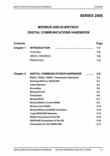
<strong>Series</strong> <strong>2000</strong> <strong>Communications</strong> <strong>Handbook</strong>ContentsSERIES <strong>2000</strong>MODBUS AND EI-BISYNCHDIGITAL COMMUNICATIONS HANDBOOKContents PageChapter 1 INTRODUCTION ………………………..…………… 1-1OverviewJBUS v MODBUSReferences1-21-21-3Chapter 2 DIGITAL COMMUNICATIONS HARDWARE …....... 2-2RS232, RS422, RS485 Transmission StandardsSeecting RS232 or RS422/485Cable SelectionGroundingWiring GeneralPrecautionsWiring RS232Wiring RS422 or 4-wire RS485Wiring 2-wire RS485Wiring RS422 and RS485 ControllersLarge RS422/485 NetworksRS232 Connections of the 261RS422/485 Connections of the 261Connections for the KD485-ADE2-22-32-42-52-52-62-72-82-102-122-142-162-162-17<strong>Series</strong> <strong>2000</strong> <strong>Communications</strong> <strong>Handbook</strong> Part No HA026230 Issue 2.0 Feb-00 i-1
Contents<strong>Series</strong> <strong>2000</strong> <strong>Communications</strong> <strong>Handbook</strong>Chapter 3 MODBUS AND JBUS PROTOCOL ......................... 3-2Protocol BasicsTypical Transmission Line ActivityDevice AddressParameter AddressParameter ResolutionMode of TransmissionMessage Frame FormatCyclic Redundancy CheckExample of a CRC CalculationExample of a CRC Calculation in the ‘C’LanguageExample of a CRC Calculation in Basic LanguageFunction CodesRead N BitsRead N WordsWrite A BitWrite A WordFast Read of StatusDiagnostic LoopbackWrite N WordsError ResponseWait PeriodLatencyMessage Transmission Time3-33-43-53-53-53-63-73-83-103-123-133-143-153-173-193-213-223-253-263-283-293-293-30i-2 <strong>Series</strong> <strong>2000</strong> <strong>Communications</strong> <strong>Handbook</strong> Part No HA026230 Issue 2.0 Feb-00
<strong>Series</strong> <strong>2000</strong> <strong>Communications</strong> <strong>Handbook</strong>ContentsChapter 4 EI-BISYNCH PROTOCOL …..........……………...…Explanation of TermsAddressMnemonicsChannelsASCII CodesControl CharactersData FormatsFree Data FormatHex Data FormatReading Data from the <strong>2000</strong> <strong>Series</strong>Fast PollRepeated Polling of the Same ParameterWriting Data to the <strong>2000</strong> <strong>Series</strong>BroadcastsError Codes held in EEBisynch Message LatencyMessage Transmission Time4-24-24-24-24-24-34-44-44-44-54-64-84-84-94-104-114-114-11Chapter 5 MODBUS AND EI-BISYNCH ADDRESSES ……… 5-2IntroductionModbus and Bisynch AddressesOperating Mode ParametersModbus and Bisynch Parameter TablesMiscellaneous Status and Comms-OnlyParametersStatus WordsModbus Bit Addressable ParametersConfiguration Mode ParametersInput/Output ModulesRamp/Dwell Programmer Data - ModbusProgram Data OrganisationProgram General DataProgram Segment DataExample Address Calculations5-25-25-35-35-175-205-245-255-335-505-505-525-535-535-54<strong>Series</strong> <strong>2000</strong> <strong>Communications</strong> <strong>Handbook</strong> Part No HA026230 Issue 2.0 Feb-00 i-3
Contents<strong>Series</strong> <strong>2000</strong> <strong>Communications</strong> <strong>Handbook</strong>Ramp/Dwell Programmer Data - EI-BisynchSummary of Programmer EnumeratorsAdditional Parameters for 2408I IndicatorOperator ParametersConfiguration Parameters5-585-595-595-60Chapter 6 DEVICENET ……………………….…. 6-1Introduction 6-22200e DeviceNet Features 6-2The EDS FilePolled I/IO Message6-36-3Parameter Explicit Messaging Encoding6-4REM Beacon OperationREM Beacon Behaviour6-46-4Troubleshooting 6-5Parameter Address Map 6-6Operarting Mode Parameters 6-7Chapter 7 ADVANCED TOPICS …………………………......... 7-2Access to Full Resolution Floating Point and Timing Data(Modbus only)Data Types Used in <strong>Series</strong> <strong>2000</strong> InstrumentsEnumerated, Status Word and Integer ParametersFloating Point ParametersTime Type ParametersUser Interface Access Permissions (Modbus)User Interface Access Permissions (EI Bisynch)Programmable Logic Controllers and 2400 <strong>Series</strong> InstrumentsEI BisynchModbus7-27-37-37-47-57-67-77-87-87-9Appendix A GLOSSARY OF TERMS ……………………….…. A-1Appendix B ASCII CODES …………………………………... B-1i-4 <strong>Series</strong> <strong>2000</strong> <strong>Communications</strong> <strong>Handbook</strong> Part No HA026230 Issue 2.0 Feb-00
<strong>Series</strong> <strong>2000</strong> <strong>Communications</strong> <strong>Handbook</strong>Introduction1. CHAPTER 1 INTRODUCTION.............................................. 21.1. OVERVIEW.........................................................................................21.2. JBUS V MODBUS ............................................................................21.3. REFERENCES....................................................................................2<strong>Series</strong> <strong>2000</strong> <strong>Communications</strong> <strong>Handbook</strong> Part No HA026230 Issue 2.0 Feb-00 1-1
Introduction<strong>Series</strong> <strong>2000</strong> <strong>Communications</strong> <strong>Handbook</strong>1. CHAPTER 1 INTRODUCTIONThis chapter describes the scope of this handbook and how to use it.1.1. OVERVIEWThis handbook is written for the people who need to use a digital communications link andMODBUS, JBUS, or EI-BISYNCH communication protocols to supervise <strong>Series</strong> <strong>2000</strong>instruments, including the 2200 and 2400 instrument models.It has been assumed that the reader has some experience of communication protocols and isfamiliar with <strong>Series</strong> <strong>2000</strong> instruments. The relevant instrument handbook gives a fulldescription of how to use the instruments, configuration options and definition of parameters.Chapter 2 of this document is a guide to cabling and the basic physical environment of digitalcommunications.Chapter 3 is a general description of the MODBUS and JBUS protocols.Chapter 4 is a general description of the EI-BISYNCH protocol.Chapter 5 lists <strong>Series</strong> <strong>2000</strong> parameter addresses and mnemonics.Chapter 6 covers advanced topics such as access to full resolution floating point data and userinterface permissions.Appendix A is a Glossary of Terms.Appendix B lists ASCII codes.No responsibility is accepted for any loss or damage caused by application of the informationcontained in this document.JBUS ® is a registered trademark of APRIL.MODBUS ® is a registered trademark of Gould Inc.1.2. JBUS V MODBUS• MODBUS is a serial communications protocol defined by Gould Inc.April developed JBUS as a special case of MODBUS.• The two protocols use the same message frame format.• The function codes used by <strong>Series</strong> <strong>2000</strong> instruments are a subset of JBUS andMODBUS function codes.• NB. <strong>Series</strong> <strong>2000</strong> JBUS addresses are exactly the same as MODBUS addresses.This differs from previous implementations of the protocol in earlier instruments.• In this document reference will be made to MODBUS, however all informationapplies equally to JBUS.1-2 <strong>Series</strong> <strong>2000</strong> <strong>Communications</strong> <strong>Handbook</strong> Part No HA026230 Issue 2.0 Feb-00
<strong>Series</strong> <strong>2000</strong> <strong>Communications</strong> <strong>Handbook</strong>Introduction1.3. REFERENCESRefer to the documents below for further information;GouldAprilEIA Standard RS-232-CEIA Standard RS-422EIA Standard RS-485MODBUS Protocol Reference Guide, PI-MBUS-300JBUS SpecificationInterface Between Terminal Equipment and Data CommunicationEquipment Employing Serial Binary InterchangeElectrical Characteristics of Balanced Voltage Digital InterfaceCircuitsElectrical Characteristics of Generators and Receivers for use inBalanced Digital Multipoint Systems<strong>Series</strong> <strong>2000</strong> <strong>Communications</strong> <strong>Handbook</strong> Part No HA026230 Issue 2.0 Feb-00 1-3
Introduction<strong>Series</strong> <strong>2000</strong> <strong>Communications</strong> <strong>Handbook</strong>1-4 <strong>Series</strong> <strong>2000</strong> <strong>Communications</strong> <strong>Handbook</strong> Part No HA026230 Issue 2.0 Feb-00
<strong>Series</strong> <strong>2000</strong> <strong>Communications</strong> <strong>Handbook</strong>Digital <strong>Communications</strong> Hardware2. CHAPTER 2 DIGITAL COMMUNICATIONS HARDWARE .. 22.1. RS232, RS422 AND RS485 TRANSMISSION STANDARDS ...........22.2. SELECTING RS232 OR RS422/485 ..................................................32.3. CABLE SELECTION ..........................................................................42.4. GROUNDING......................................................................................52.5. WIRING GENERAL ............................................................................52.6. PRECAUTIONS ..................................................................................62.7. WIRING RS232...................................................................................72.8. WIRING RS422 OR 4-WIRE RS485...................................................82.9. WIRING 2-WIRE485 .........................................................................102.10. WIRING RS422 AND RS485 CONTROLLERS .............................122.11. LARGE RS422/485 NETWORKS...................................................142.12. RS232 CONNECTIONS OF THE 261 ............................................162.13. RS422/485 CONNECTIONS OF THE 261 .....................................162.14. CONNECTIONS FOR THE KD485-ADE........................................17<strong>Series</strong> <strong>2000</strong> <strong>Communications</strong> <strong>Handbook</strong> Part No HA026230 Issue 2.0 Feb-00 2-1
Digital <strong>Communications</strong> Hardware<strong>Series</strong> <strong>2000</strong> <strong>Communications</strong> <strong>Handbook</strong>2. CHAPTER 2 DIGITAL COMMUNICATIONSHARDWAREThis chapter defines the differences between the RS232, RS422 and RS485 digitalcommunications standards. Details of configuration, cabling and termination will help toestablish basic communications.2.1. RS232, RS422 AND RS485 TRANSMISSION STANDARDSThe Electrical Industries Association, (EIA) introduced the Recommended Standards, RS232,RS422 and RS485. These standards define the electrical performance of a communicationsnetwork. The table below is a summary of the different physical link offered by the threestandards.EIA Standard RS232C RS422 RS485Transmission mode Single ended Differential DifferentialElectrical connections 3 wire 5 wire 3 wireNo. of drivers and receiversper line1 driver,1 receiver1 driver,10 receivers32 drivers,32 receiversMaximum data rate 20k bits/s 10M bits/s 10M bits/sMaximum cable length 50ft, (15M) 4000ft, (1200M) 4000ft, (1200M)Note: RS232C has been abbreviated to RS232. The RS232 standard allows a singleinstrument to be connected to a PC, a Programmable Logic Controller, or similar devicesusing a cable length of less than 15M.The RS485 standard allows one or more instruments to be connected (multi-dropped) usinga two wire connection, with cable length of less than 1200M. 31 Instruments and one‘master’ may be connected in this way. The balanced differential signal transmission is lessprone to interference and should be used in preference to RS232 in noisy environments.RS422/RS485 is recommended for plant installation. Although RS485 is commonly referredto as a ‘two wire’ connection, a ground return/shield connection is provided as a ‘common’connection for <strong>Series</strong> <strong>2000</strong> Instruments, and in general this should be used in installations toprovide additional protection against noise.2-2 <strong>Series</strong> <strong>2000</strong> <strong>Communications</strong> <strong>Handbook</strong> Part No HA026230 Issue 2.0 Feb-00
<strong>Series</strong> <strong>2000</strong> <strong>Communications</strong> <strong>Handbook</strong>Digital <strong>Communications</strong> HardwareStrictly speaking, RS422 is a standard permitting ‘point to point’ connection of two pieces ofequipment using a full duplex, differential signal on two pairs of wires. In principle,therefore, an RS422 link only allows a single instrument to be connected to a PC. However,<strong>Series</strong> <strong>2000</strong> instruments provide an enhanced version of RS422 that also meets the fullelectrical requirements of RS485 described above. This allows up to 31 instruments to beconnected on the same network, but only with a 5 wire electrical connection. Thetransmission and reception of data use two pairs of twisted cable, with a separate cableprovided for common. The optional screen will provide additional noise immunity.The 2 wire RS485 should be used where possible for new installations where multi-dropcapability is required. RS422 is provided for compatibility with existing instruments.Some earlier instruments use a terminal marking that is different from that used in theRS422/RS485 standards. The table below compares this marking.RS422/RS485A'B'ABC & C'InstrumentRX+RX-TX+TX-CommonUsing RS232 or RS422/485, the <strong>Series</strong> <strong>2000</strong> instruments operate in a half duplex mode thatdoes not allow the simultaneous transmission and reception of data. Data is passed by analternating exchange.Most PC's provide an RS232 port for digital communications. The KD485 Comms Interfaceunit is recommended for interfacing to RS422/485. This unit is also used to buffer anRS422/485 network when it is required to communicate with more than 32 instruments onthe same bus, and may also be used to bridge 2 wire RS485 to 4 wire RS422 networksegments.. Wiring information for this unit is given at the end of this chapter., or refer toKD485 Installation and Operation Manual, available on request from your supplier, for a fulldescription.2.2. SELECTING RS232 OR RS422/485Changing between RS232, RS422, and RS485 is possible for 2400 <strong>Series</strong> instruments byreplacing the plug-in ‘H’ Module with a communications module of the required type.2200 <strong>Series</strong> communications hardware is a fixed build and must be specified when theinstrument is being ordered.<strong>Series</strong> <strong>2000</strong> <strong>Communications</strong> <strong>Handbook</strong> Part No HA026230 Issue 2.0 Feb-00 2-3
Digital <strong>Communications</strong> Hardware<strong>Series</strong> <strong>2000</strong> <strong>Communications</strong> <strong>Handbook</strong>2.3. CABLE SELECTIONThe cable selected for the digital communications network should have the followingelectrical characteristics:• Less than 100 ohm / km nominal dc resistance. Typically 24 AWG or thicker.• Nominal characteristic impedance at 100 kHz of 100 ohms.• Less than 60 pF / m mutual pair capacitance, (the capacitance between two wires in apair).• Less than 120 pF / m stray capacitance, (the capacitance between one wire and all othersconnected to ground).• For RS422/485 applications, use twisted pair cables.The selection of a cable is a trade off between cost and quality factors such as attenuation andthe effectiveness of screening. For applications in an environment where high levels ofelectrical noise are likely, use a cable with a copper braid shield, (connect the shield to anoise free ground). For applications communicating over longer distances, choose a cablethat also has low attenuation characteristics.In low noise applications and over short distances it may be possible to use the groundedscreen as the common connection. Connect the common to the grounded screen via a 100ohm, 1/4W carbon composition resistor at the PC and all instruments.For RS422/485 it is possible to operate the system with unscreened twisted data pairs, groundis used as the common connection. Connect the common to ground via a 100 ohm, 1/4Wcarbon composition resistor at the PC and all instruments. This system is not recommended.The following list is a selection of cables suitable for RS 422/485 communication systems,listed in order of decreasing quality.Cables marked '*' are suitable for use with the wiring descriptions that follow.Cables marked '**' use a different colour coding from that used in the wiring descriptions.BeldenNoDescription9842 2 twisted pairs with aluminium foil screen plus a 90% coverage copper screen **9843 3 twisted pairs with aluminium foil screen plus a 90% coverage copper screen **9829 2 twisted pairs with aluminium foil screen plus a 90% coverage copper screen9830 3 twisted pairs with aluminium foil screen plus a 90% coverage copper screen *8102 2 twisted pairs with aluminium foil screen plus a 65% coverage copper screen8103 3 twisted pairs with aluminium foil screen plus a 65% coverage copper screen *9729 2 twisted pairs with aluminium foil screen9730 3 twisted pairs with aluminium foil screen *2-4 <strong>Series</strong> <strong>2000</strong> <strong>Communications</strong> <strong>Handbook</strong> Part No HA026230 Issue 2.0 Feb-00
<strong>Series</strong> <strong>2000</strong> <strong>Communications</strong> <strong>Handbook</strong>Digital <strong>Communications</strong> HardwareThe following are a selection of cables suitable for RS 232 communication systems listed inorder of decreasing quality;Part numberAlpha Belden Description8102 2 twisted pairs with aluminium foil screen plus a 65% coveragecopper screen **5472 9502 2 twisted pairs with aluminium foil screen *2403 8771 3 separate wires with aluminium foil screen **2.4. GROUNDINGEnsure all ground points are noise free.To reduce interference from external electrical signals, ground the cable screen at a singleground point. There must not be multiple ground paths in a single cable run. When using aKD485 <strong>Communications</strong> Adapter unit, do not connect the screen from one side of theinterface to the other. Rather, ground each of the cables separately at a local ground point.The digital communication outputs of all <strong>Series</strong> <strong>2000</strong> instruments are isolated. To avoidcommon mode noise problems, connect the common line to ground at one point through a100 ohm, 1/4W, carbon composition resistor. The resistor will limit the ground current.2.5. WIRING GENERALRoute communications cables in separate trunking to power cables. Power cables arethose connecting power to instruments, relay or triac ac supplies and wiring associated withexternal switching devices such as contactors, relays or motor speed drives.Communication cables may be routed with control signal cables if these signal cables are notexposed to an interference source. Control signals are the analogue or logic inputs andanalogue or logic outputs of any control instrument.Do not use redundant wires in the communications cable for other signals.Ensure cable runs have sufficient slack to ensure that movement does not cause abrasion ofthe insulating sheath. Do not over tighten cable clamps to avoid accidental multiplegrounding of the screen conductors.Ensure that the cable is ‘daisy chained’ between instruments, i.e. the cable runs from oneinstrument to the next to the final instrument in the chain.<strong>Series</strong> <strong>2000</strong> <strong>Communications</strong> <strong>Handbook</strong> Part No HA026230 Issue 2.0 Feb-00 2-5
<strong>Series</strong> <strong>2000</strong> <strong>Communications</strong> <strong>Handbook</strong>Digital <strong>Communications</strong> Hardware2.7. WIRING RS232To use RS232 the PC will be equipped with an RS232 port, usually referred to as COM 1.To construct a cable for RS232 operation use a three core screened cable.The terminals used for RS232 digital communications are listed in the table below. SomePC's use a 25 way connector although the 9 way is more common.Standard Cable PC socket pin no. PC Function * InstrumentTerminalInstrumentColour 9 way 25 way FunctionWhite 2 3 Receive (RX) HF Transmit (TX)Black 3 2 Transmit (TX) HE Receive (RX)Red 5 7 Common HD CommonLink together 146Link together 78681145Rec'd line sig.detect Data terminalreadyData set readyRequest to sendClear to sendScreen 1 Ground• These are the functions normally assigned to socket pins. Please check your PC manualto confirm.RxTxComTx HFRx HECom HDComputerLocal ground<strong>2000</strong> <strong>Series</strong>ControllerFigure 2-1 RS232 Connections<strong>Series</strong> <strong>2000</strong> <strong>Communications</strong> <strong>Handbook</strong> Part No HA026230 Issue 2.0 Feb-00 2-7
Digital <strong>Communications</strong> Hardware<strong>Series</strong> <strong>2000</strong> <strong>Communications</strong> <strong>Handbook</strong>2.8. WIRING RS422 OR 4-WIRE RS485To use RS422, buffer the RS232 port of the PC with a suitable RS232/RS422 converter.The KD485 or 261 <strong>Communications</strong> Converter unit is recommended for this purpose.Figure 2.6 shows connections for this unit. Instruments on a RS422 communicationnetwork should be chain connected and not star connected.To construct a cable for RS422 operation use a screened cable with two twisted pairs plus aseparate core for common. Although common or screen connections are not necessary, theiruse will significantly improve noise immunity.The terminals used for RS422 digital communications are listed in the table below.Standard Cable PC socket pin no. PC Function * Instrument Terminal InstrumentColour 25 way 902-4 2400 FunctionWhite 3 Receive (RX+) F1 HE Transmit(TX+)Black 16 Receive (RX-) F2 HF Transmit(TX-)Red 12 Transmit (TX+) F3 HB Receive(RX+)Black 13 Transmit (TX-) F4 HC Receive (RX-)Green 7 Common F5 HD CommonScreen 1 Ground• These are the functions normally assigned to socket pins. Please check your PC manualto confirm.2-8 <strong>Series</strong> <strong>2000</strong> <strong>Communications</strong> <strong>Handbook</strong> Part No HA026230 Issue 2.0 Feb-00
<strong>Series</strong> <strong>2000</strong> <strong>Communications</strong> <strong>Handbook</strong>Digital <strong>Communications</strong> HardwarePCNOTESThis diagram shows a typical installation which maybe in use with existing controllers, such as 800 seriesor 900 series.Com TxRxRS232It is possible to substitute an existing controller, or toadd to the current installation, with a 2400 seriescontroller provided it has been supplied as 4-wireEIA485.CoRx TxType 261converter220 ohmterminationresistoron the Rx of theconverter unitRepresents twistedpairsRS422To add any other <strong>2000</strong> series please refer to Figure 2-4It is preferable to ground cable screen at both endsBUT it is essential to ensure that both are atequipotential. If this cannot be guaranteed ground atone end, as shown.The value of terminating resistors is not critical,100 - 300 ohms is typical.Tx- Com Rx+Tx+ Rx-Rx+ Tx-Rx+ Tx-Rx- Com Tx+Rx- Com Tx+Controller 1 Controller 2220 ohmterminationresistoron the Rxterminals onlastcontroller inthe chainAdditionalControllersFigure 2-2 Controllers (1-31) Connected to a PC using RS422 Standard<strong>Series</strong> <strong>2000</strong> <strong>Communications</strong> <strong>Handbook</strong> Part No HA026230 Issue 2.0 Feb-00 2-9
Digital <strong>Communications</strong> Hardware<strong>Series</strong> <strong>2000</strong> <strong>Communications</strong> <strong>Handbook</strong>2.9. WIRING 2-WIRE485To use RS485, buffer the RS232 port of the PC with a suitable RS232/RS485 converter. TheKD485 <strong>Communications</strong> Adapter unit is recommended for this purpose. The use of a RS485board built into the computer is not recommended since this board is unlikely to be isolated,which may cause noise problems, and the Rx terminals are unlikely to be biased correctly forthis application.To construct a cable for RS485 operation use a screened cable with one (RS485) twisted pairplus a separate core for common. Although common or screen connections are not necessary,their use will significantly improve noise immunity.The terminals used for RS485 digital communications are listed in the table below.StandardCable ColourPC socket pinno. 25 wayPC Function * Instrument Terminal InstrumentFunctionWhite 3 Receive (RX+) HF (B) or (B+) Transmit (TX)Black 16 Receive (RX-)Red 12 Transmit (TX+) HE (A) or (A+) Receive (RX)Black 13 Transmit (TX-)Green 7 Common HD CommonScreen 1 Ground* These are the functions normally assigned to socket pins. Please check your PC manual toconfirm .2-10 <strong>Series</strong> <strong>2000</strong> <strong>Communications</strong> <strong>Handbook</strong> Part No HA026230 Issue 2.0 Feb-00
<strong>Series</strong> <strong>2000</strong> <strong>Communications</strong> <strong>Handbook</strong>Digital <strong>Communications</strong> HardwarePCComTx RxCo Rx TxTypeKD485converterTxB Com RxATxA RxBRS232220 ohmterminationresistoron the Rx of theconverter unitTwisted pairsRS485Com HFHEController 1eg Type 2400Com HFHEController 2eg Type 2200220 ohmterminationresistoron the lastcontroller in thechainAdditionalControllersFigure 2-3 <strong>2000</strong> <strong>Series</strong> Controllers (1 to 31) Connected to a PC using 2-wire RS485Standard<strong>Series</strong> <strong>2000</strong> <strong>Communications</strong> <strong>Handbook</strong> Part No HA026230 Issue 2.0 Feb-00 2-11
Digital <strong>Communications</strong> Hardware<strong>Series</strong> <strong>2000</strong> <strong>Communications</strong> <strong>Handbook</strong>2.10. WIRING RS422 AND RS485 CONTROLLERSIt is generally not possible to mix controllers using a 2-wire and 4-wire standards. However,in some cases it may be required to add new controllers (such as <strong>2000</strong> series on 2-wirecomms) to an existing installation with controllers on 4-wire comms.In these cases the existing communications link may be modified by adding a special versionof the KD485 converter unit, supplied as KD485-ADE 422-422. Figure 2-4 shows a largesystem of controllers using a mixture of both standards.The standard KD485 unit converts from 232 to 4-wire 485 and this link is used tocommunicate to the first 32 existing controllers. The second KD485 is the special versionwhich converts from 4-wire to 4-wire communications to communicate with a further bank of32 controllers on 4-wire communications. The third KD485 is the same special version whichis connected to convert from 4-wire to 2-wire communications. It’s input side behaves to the4-wire link as another controller would on an existing system, whilst at the same time thecommunications messages from the computer are passed onto the output side of this unit.This is connected to the 2-wire communications link, that will contain the series <strong>2000</strong>controllers. Any responses from controllers on this link will cause data to be placed on to the4-wire link and thence will be passed back to the computer.2-12 <strong>Series</strong> <strong>2000</strong> <strong>Communications</strong> <strong>Handbook</strong> Part No HA026230 Issue 2.0 Feb-00
<strong>Series</strong> <strong>2000</strong> <strong>Communications</strong> <strong>Handbook</strong>Digital <strong>Communications</strong> HardwareComComPCTxRxRx TxType 261 orKD485TxB Com RxATxA RxBRS232220 ohmterminationresistorTwisted pairsRS422The comms connections required for large systems are amixture of 2-wire and 4-wire comms. Controllers 1 to 31are 4-wire, Controllers 32 to 64 are 4-wire, controllers 65to 97 are 2-wire.Notes:1. It is possible to connect 4-wire to 2-wire. It is notpossible to connect 2-wire to 4-wire.2. If it is necessary to configure the KD485 422-422,please note that an additional 232 to 422 converter isnecessary for this.220 ohmterminationresistor onthe last unitin the chainRx+ Tx-Rx- Com Tx+Controller 1Rx+ Tx-Rx- Com Tx+Controllers 2to 31RxB RxA ComTxB TxAKD485-ADE 422-422TxA TxB RxA RxBRxB RxA Com TxB TxAKD485-ADE 422-422TxB TxA RxB RxAControllers33 to 64eg Type902Rx-Controller 32 Rx+ComTx-Tx+220 ohmterminationresistoron the lastcontroller in thechain220 ohmterminationresistorsController 65Controllers66 to 97RxHETxHFFigure 2-4 Comms Connections Required for Large Systems<strong>Series</strong> <strong>2000</strong> <strong>Communications</strong> <strong>Handbook</strong> Part No HA026230 Issue 2.0 Feb-00 2-13
Digital <strong>Communications</strong> Hardware<strong>Series</strong> <strong>2000</strong> <strong>Communications</strong> <strong>Handbook</strong>2.11. LARGE RS422/485 NETWORKSNetworks with more than 32 instruments will require buffering of the communication lines.The KD485-ADE 422-422, Universal Serial Interface unit is recommended for this purpose.The KD485 in this format sets the Transmit line's to non tristate.NOTE Large networks using RS422 4-wire controllers could use type 261 Universal SerialInterface Unit. To set the transmit lines to non tristate in 261, change links 4 and 5 fromposition B to A.Contact your supplier for further information when specifying large networks .Instruments on a RS422/485 communication network should be chain connected and not starconnected.The diagram below illustrates the wiring of a network for communicating with a largenumber of <strong>2000</strong> <strong>Series</strong> controllers.2-14 <strong>Series</strong> <strong>2000</strong> <strong>Communications</strong> <strong>Handbook</strong> Part No HA026230 Issue 2.0 Feb-00
<strong>Series</strong> <strong>2000</strong> <strong>Communications</strong> <strong>Handbook</strong>Digital <strong>Communications</strong> HardwarePCComTxRxComTxBTxARxTxType KD485converterRxBRxA220 ohmterminatingresistorTwisted pairs220 ohmterminating resistorRxARxARxBRxBTxATxATxBTxB220 ohmterminatingresistor onthe lastcontrollerHE HF HE HFKD485-ADE422-422RxARxARxBRxBTxATxATxBTxBController1HE HFController31220 ohmterminating resistoron the lastcontrollerHEHFRepeat forfurthercontrollers inthe chain220 ohmterminating resistorsController32Controller62Figure 2-5 Large RS422/485 Networks<strong>Series</strong> <strong>2000</strong> <strong>Communications</strong> <strong>Handbook</strong> Part No HA026230 Issue 2.0 Feb-00 2-15
Digital <strong>Communications</strong> Hardware<strong>Series</strong> <strong>2000</strong> <strong>Communications</strong> <strong>Handbook</strong>2.12. RS232 CONNECTIONS OF THE 261Standard Cable PC socket pin no. PC Function * 261Colour 9 way 25 way Terminal FunctionWhite 2 3 Receive (RX) 2 Transmit(TX)Black 3 2 Transmit (TX) 3 Receive(RX)Red 5 7 Common 7 CommonScreen 1 Ground* These are the functions normally assigned to socket pins. Please check your PC manual toconfirm.2.13. RS422/485 CONNECTIONS OF THE 261Standard Cable PC socket pin no. PC Function * 261Colour 25 way Terminal FunctionWhite 3 Receive (RX+) 12 Transmit (TX+)Black 16 Receive (RX-) 13 Transmit (TX-)Red 12 Transmit (TX+) 3 Receive (RX+)Black 13 Transmit (TX-) 16 Receive (RX-)Green 7 Common 7 CommonScreen 1 Ground* These are the functions normally assigned to socket pins. Please check your PC manual toconfirm.2-16 <strong>Series</strong> <strong>2000</strong> <strong>Communications</strong> <strong>Handbook</strong> Part No HA026230 Issue 2.0 Feb-00
<strong>Series</strong> <strong>2000</strong> <strong>Communications</strong> <strong>Handbook</strong>Digital <strong>Communications</strong> Hardware2.14. CONNECTIONS FOR THE KD485-ADEHRxARxELRxBTxFPort 1HOST SIDE(RS232)Port 2ISOLATED SIDE(RS422)GTxAKTxBComAMCom0VPowerSupplyD+12VFigure 2-6 Terminal Connections for the KD485Further details are available in KD485 Installation and Operation <strong>Handbook</strong><strong>Series</strong> <strong>2000</strong> <strong>Communications</strong> <strong>Handbook</strong> Part No HA026230 Issue 2.0 Feb-00 2-17
Digital <strong>Communications</strong> Hardware<strong>Series</strong> <strong>2000</strong> <strong>Communications</strong> <strong>Handbook</strong>2-18 <strong>Series</strong> <strong>2000</strong> <strong>Communications</strong> <strong>Handbook</strong> Part No HA026230 Issue 2.0 Feb-00
<strong>Series</strong> <strong>2000</strong> <strong>Communications</strong> <strong>Handbook</strong>MODBUS and JBUS Protocol3. CHAPTER 3 MODBUS AND JBUS PROTOCOL................ 23.1. PROTOCOL BASICS .......................................................................................23.2. TYPICAL TRANSMISSION LINE ACTIVITY ............................................43.3. DEVICE ADDRESS ..........................................................................................43.4. PARAMETER ADDRESS ................................................................................53.5. PARAMETER RESOLUTION ........................................................................53.6. MODE OF TRANSMISSION...........................................................................53.7. MESSAGE FRAME FORMAT .......................................................................63.8. CYCLIC REDUNDANCY CHECK.................................................................73.9. EXAMPLE OF A CRC CALCULATION.......................................................93.10. EXAMPLE OF A CRC CALCULATION IN THE ‘C’ LANGUAGE......113.11. EXAMPLE OF A CRC CALCULATION IN BASIC LANGUAGE ........123.12. FUNCTION CODES .....................................................................................133.13. READ N BITS................................................................................................143.14. READ N WORDS ..........................................................................................163.15. WRITE A BIT................................................................................................183.16. WRITE A WORD..........................................................................................203.17. FAST READ OF STATUS............................................................................213.18. DIAGNOSTIC LOOPBACK........................................................................243.19. WRITE N WORDS........................................................................................253.20. ERROR RESPONSE.....................................................................................273.21. WAIT PERIOD..............................................................................................283.22. LATENCY......................................................................................................283.23. MESSAGE TRANSMISSION TIME...........................................................29<strong>Series</strong> <strong>2000</strong> <strong>Communications</strong> <strong>Handbook</strong> Part No HA026230 Issue 2.0 Feb-00 3-1
MODBUS and JBUS Protocol<strong>Series</strong> <strong>2000</strong> <strong>Communications</strong> <strong>Handbook</strong>3. CHAPTER 3 MODBUS AND JBUS PROTOCOLThis chapter introduces the principles of the MODBUS and JBUS communication protocols.Note that in the <strong>Series</strong> <strong>2000</strong>, these two protocols are identical, and both will be referred to asMODBUS for the descriptions that follow.3.1. PROTOCOL BASICSA data communication protocol defines the rules and structure of messages used by alldevices on a network for data exchange. This protocol also defines the orderly exchange ofmessages, and the detection of errors.MODBUS defines a digital communication network to have only one MASTER and one ormore SLAVE devices. Either a single or multi-drop network is possible. The two types ofcommunications networks are illustrated in the diagram below;5KPING 5GTKCN .KPM/WNVK &TQR 5GTKCN .KPMJBUS MasterJBUS MasterTXRXTXRXvRX^RS232TXvRX^TX^vRS485vRX^TXJBUS Slave 1JBUS Slave 1JBUS Slave NA typical transaction will consist of a request sent from the master followed by a responsefrom the slave.The message in either direction will consist of the following information;Device Address Function Code Data Error Check Data End of Transmission• Each slave has a unique 'device address'• The device address 0 is a special case and is used for messages broadcast to allslaves. This is restricted to parameter write operations.• <strong>Series</strong> <strong>2000</strong> supports a subset of Modbus function codes.• The data will include instrument parameters referenced by a 'parameter address'3-2 <strong>Series</strong> <strong>2000</strong> <strong>Communications</strong> <strong>Handbook</strong> Part No HA026230 Issue 2.0 Feb-00
<strong>Series</strong> <strong>2000</strong> <strong>Communications</strong> <strong>Handbook</strong>MODBUS and JBUS Protocol• Sending a communication with a unique device address will cause only the devicewith that address to respond. That device will check for errors, perform the requested taskand then reply with its own address, data and a check sum.• Sending a communication with the device address '0' is a broadcast communicationthat will send information to all devices on the network. Each will perform the requiredaction but will not transmit a reply.<strong>Series</strong> <strong>2000</strong> <strong>Communications</strong> <strong>Handbook</strong> Part No HA026230 Issue 2.0 Feb-00 3-3
MODBUS and JBUS Protocol<strong>Series</strong> <strong>2000</strong> <strong>Communications</strong> <strong>Handbook</strong>3.2. TYPICAL TRANSMISSION LINE ACTIVITYThis diagram is to illustrate typical sequence of events on a Modbus transmission line.ACTIVITYMasterTo slave 1bTo slave NbBroadcastcSlave 1aReplyaSlave NaReplyaNetworkMasterSlave 1MasterSlave 2MasterTIME >Period 'a' The processing time, (latency), required by the slave to complete the command andconstruct a reply.Period 'b' The processing time required by the master to analyse the slave response andformulate the next command.Period 'c' The wait time calculated by the master for the slaves to perform the operation.None of the slaves will reply to a broadcast message.For a definition of the time periods required by the network, refer to 'Wait Period' in thesection 'Error Response'.3.3. DEVICE ADDRESSEach slave has a unique 8 bit device address. The Gould MODBUS Protocol defines theaddress range limits as 1 to 247. <strong>Series</strong> <strong>2000</strong> instruments will support an address range of 1to 254. The device address used by the instrument is set using the 5 parameter in the, )O6, which is available in operator mode. Note that this list may only be accessiblewhen using the 9)) user interface: refer to the manual supplied with the instrument formore details on how to set this parameter.Device address 0 is a special case that will broadcast a message to all slave devicessimultaneously.3-4 <strong>Series</strong> <strong>2000</strong> <strong>Communications</strong> <strong>Handbook</strong> Part No HA026230 Issue 2.0 Feb-00
<strong>Series</strong> <strong>2000</strong> <strong>Communications</strong> <strong>Handbook</strong>MODBUS and JBUS Protocol3.4. PARAMETER ADDRESSData bits or data words exchange information between master and slave devices. This dataconsists of parameters. All parameters communicated between master and slaves have a 16bit parameter address.The MODBUS parameter address range is 0001 to FFFF..Parameter definitions for <strong>Series</strong> <strong>2000</strong> instruments are in Chapter 5.3.5. PARAMETER RESOLUTIONJBUS and MODBUS protocol limit data to 16 bits per parameter. This reduces the activerange of parameters to 65536 counts. In <strong>Series</strong> <strong>2000</strong> instruments this is implemented as -32767 (8001h) to +32767 (7FFFh).The protocol is also limited to integer communication only. <strong>Series</strong> <strong>2000</strong> instruments allowthe user to configure either integer or full resolution. In integer mode all parameters will berounded to the nearest integer value, whereas in full resolution mode the decimal pointposition will be implied so that 100.01 would be transmitted as 10001. From this, and the 16bit resolution limitation, the maximum value communicable with 2 decimal place resolutionis 327.67. The parameter resolution will be taken from the slave user interface, and theconversion factor must be known to both master and slave when the network is initiated.The <strong>Series</strong> <strong>2000</strong> instruments provide a special sub-protocol for accessing full resolutionfloating point data. This is described in Chapter 6 of this manual.3.6. MODE OF TRANSMISSIONThe mode of transmission describes the structure of information within a message and thenumber coding system used to exchange a single character of data.The JBUS and MODBUS Protocols define a mode of transmission for both ASCII and RTUmodes of transmission. <strong>Series</strong> <strong>2000</strong> instruments only support the RTU mode oftransmission.The RTU definition of the mode of transmission for a single character is;A start bit, eight data bits, a parity bit and one or two stop bitsAll <strong>Series</strong> <strong>2000</strong> instruments use 1 stop bit.Parity may be configured to be NONE, ODD or EVEN.If parity is configured to be NONE, no parity bit is transmitted.The RTU mode of transmission for a single character is represented as follows:Start d7 d6 d5 d4 d3 d2 d1 d0 Parity Stop<strong>Series</strong> <strong>2000</strong> <strong>Communications</strong> <strong>Handbook</strong> Part No HA026230 Issue 2.0 Feb-00 3-5
MODBUS and JBUS Protocol<strong>Series</strong> <strong>2000</strong> <strong>Communications</strong> <strong>Handbook</strong>3.7. MESSAGE FRAME FORMAT# OGUUCIG EQPUKUVU QH C PWODGT QH EJCTCEVGTU UGSWGPEGF UQ VJCV VJG TGEGKXKPI FGXKEG ECPWPFGTUVCPF 6JKU UVTWEVWTG KU MPQYP CU VJG OGUUCIG HTCOG HQTOCV6JG HQNNQYKPI FKCITCO UJQYU VJG UGSWGPEG FGHKPKPI VJG OGUUCIG HTCOG HQTOCV WUGF D[,$75 CPF /1&$75(TCOG UVCTV &GXKEG CFFTGUU (WPEVKQP EQFG &CVC %4% '16 D[VGU D[VG D[VG P D[VGU D[VG D[VGU6JG HTCOG UVCTV KU C RGTKQF QH KPCEVKXKV[ CV NGCUV VKOGU VJG UKPING EJCTCEVGT VTCPUOKUUKQPVKOG(QT GZCORNG CV DCWF C EJCTCEVGT YKVJ UVCTV UVQR CPF FCVC DKVU YKNN TGSWKTG COU HTCOG UVCTV6JKU RGTKQF KU VJG KORNKGF '16 QH C RTGXKQWU VTCPUOKUUKQP6JG FGXKEG CFFTGUU KU C UKPING D[VG DKVU WPKSWG VQ GCEJ FGXKEG QP VJG PGVYQTM(WPEVKQP EQFGU CTG C UKPING D[VG KPUVTWEVKQP VQ VJG UNCXG FGUETKDKPI VJG CEVKQP VQ RGTHQTO6JG FCVC UGIOGPV QH C OGUUCIG YKNN FGRGPF QP VJG HWPEVKQP EQFG CPF VJG PWODGT QH D[VGUYKNN XCT[ CEEQTFKPIN[6[RKECNN[ VJG FCVC UGIOGPV YKNN EQPVCKP C RCTCOGVGT CFFTGUU CPF VJG PWODGT QH RCTCOGVGTUVQ TGCF QT YTKVG6JG %[ENKE 4GFWPFCPE[ %JGEM %4% KU CP GTTQT EJGEM EQFG CPF KU VYQ D[VGU DKVUNQPI6JG 'PF QH 6TCPUOKUUKQP UGIOGPV '16 KU C RGTKQF QH KPCEVKXKV[ VKOGU VJG UKPINGEJCTCEVGT VTCPUOKUUKQP VKOG 6JG '16 UGIOGPV CV VJG GPF QH C OGUUCIG KPFKECVGU VQ VJGNKUVGPKPI FGXKEG VJCV VJG PGZV VTCPUOKUUKQP YKNN DG C PGY OGUUCIG CPF VJGTGHQTG C FGXKEGCFFTGUU EJCTCEVGT3-6 <strong>Series</strong> <strong>2000</strong> <strong>Communications</strong> <strong>Handbook</strong> Part No HA026230 Issue 2.0 Feb-00
<strong>Series</strong> <strong>2000</strong> <strong>Communications</strong> <strong>Handbook</strong>MODBUS and JBUS Protocol3.8. CYCLIC REDUNDANCY CHECK6JG %[ENKE 4GFWPFCPE[ %JGEM %4% KU CP GTTQT EJGEM EQFG CPF KU VYQ D[VGU DKVUNQPI #HVGT EQPUVTWEVKPI C OGUUCIG FCVC QPN[ PQ UVCTV UVQR QT RCTKV[ DKVU VJGVTCPUOKVVKPI FGXKEG ECNEWNCVGU C %4% EQFG CPF CRRGPFU VJKU VQ VJG GPF QH VJG OGUUCIG #TGEGKXKPI FGXKEG YKNN ECNEWNCVG C %4% EQFG HTQO VJG OGUUCIG KV JCU TGEGKXGF +H VJKU %4%EQFG KU PQV VJG UCOG CU VJG VTCPUOKVVGF %4% VJGTG JCU DGGP C EQOOWPKECVKQP GTTQT 5GTKGU KPUVTWOGPVU FQ PQV TGRN[ KH VJG[ FGVGEV C %4% GTTQT KP OGUUCIGU UGPV VQ VJGO6JG %4% EQFG KU HQTOGF D[ VJG HQNNQYKPI UVGRU.QCF C DKV %4% TGIKUVGT YKVJ ((((J 'ZENWUKXG 14 ⊕ VJG HKTUV DKV D[VG QH VJG OGUUCIG YKVJ VJG YKVJ VJG JKIJ QTFGTD[VG QH VJG %4% TGIKUVGT4GVWTP VJG TGUWNV VQ VJG %4% TGIKUVGT5JKHV VJG %4% TGIKUVGT QPG DKV VQ VJG TKIJV +H VJG QXGT HNQY DKV QT HNCI KU GZENWUKXG 14 VJG %4% TGIKUVGT YKVJ # JGZCPF TGVWTP VJG TGUWNV VQ VJG %4% TGIKUVGTC+H VJG QXGTHNQY HNCI KU TGRGCV UVGR 4GRGCV UVGRU CPF WPVKN VJGTG JCXG DGGP UJKHVU 'ZENWUKXG 14 VJG PGZV DKV D[VG QH VJG OGUUCIG YKVJ VJG JKIJ QTFGT D[VG QH VJG%4% TGIKUVGT 4GRGCV UVGR VJTQWIJ VQ WPVKN CNN D[VGU QH VJG OGUUCIG JCXG DGGP GZENWUKXG 14YKVJ VJG %4% TGIKUVGT CPF UJKHVGF VKOGU 6JG EQPVGPVU QH VJG %4% TGIKUVGT CTG VJG D[VG %4% GTTQT EQFG CPF CTG CFFGF VQVJG OGUUCIG YKVJ VJG OQUV UKIPKHKECPV DKVU HKTUV<strong>Series</strong> <strong>2000</strong> <strong>Communications</strong> <strong>Handbook</strong> Part No HA026230 Issue 2.0 Feb-00 3-7
MODBUS and JBUS Protocol<strong>Series</strong> <strong>2000</strong> <strong>Communications</strong> <strong>Handbook</strong>The flow chart below illustrates this CRC error check algorithm.The '⊕' symbol indicates an 'exclusive OR' operation. 'n' is the number of data bits.STARTFFFFh → CRC RegisterCRC Register ⊕ next byte of the message → CRC Register0 → nShift CRC Register right 1 bitNOOver flow ?YESCRC Register ⊕ A001h → CRC Registern + 1 → nNOn > 7 ?YESCRC Register ⊕ next byte of the message → CRC RegisterNOIs message complete ?YESEND3-8 <strong>Series</strong> <strong>2000</strong> <strong>Communications</strong> <strong>Handbook</strong> Part No HA026230 Issue 2.0 Feb-00
<strong>Series</strong> <strong>2000</strong> <strong>Communications</strong> <strong>Handbook</strong>MODBUS and JBUS Protocol3.9. EXAMPLE OF A CRC CALCULATIONThis example is a request to read from the slave unit at address 02, the fast read of the status(07).Function 16 Bit Register CarryLSB MSB flagLoad register with FFFF hex 1111 1111 1111 1111 0First byte of the message (02) 0000 0010Exclusive OR 1111 1111 1111 11011st shift right 0111 1111 1111 1110 1A001 1010 0000 0000 0001Exclusive OR (carry = 1) 1101 1111 1111 11112nd shift right 0110 1111 1111 1111 1A001 1010 0000 0000 0001Exclusive OR (carry = 1) 1100 1111 1111 11103rd shift right 0110 0111 1111 1111 04th shift right (carry = 0) 0011 0011 1111 1111 1A001 1010 0000 0000 0001Exclusive OR (carry = 1) 1001 0011 1111 11105th shift right 0100 1001 1111 1111 06th shift right (carry = 0) 0010 0100 1111 1111 1A001 1010 0000 0000 0001Exclusive OR (carry = 1) 1000 0100 1111 11107th shift right 0100 0010 0111 1111 08th shift right (carry = 0) 0010 0001 0011 1111 1A001 1010 0000 0000 0001Exclusive OR (carry = 1) 1000 0001 0011 1110Next byte of the message (07) 0000 0111Exclusive OR (shift = 8) 1000 0001 0011 10011st shift right 0100 0000 1001 1100 1A001 1010 0000 0000 0001Exclusive OR (carry = 1) 1110 0000 1001 11012nd shift right 0111 0000 0100 1110 1A001 1010 0000 0000 0001Exclusive OR (carry = 1) 1101 0000 0100 11113rd shift right 0110 1000 0010 0111 1A001 1010 0000 0000 0001Exclusive OR (carry = 1) 1100 1000 0010 0110<strong>Series</strong> <strong>2000</strong> <strong>Communications</strong> <strong>Handbook</strong> Part No HA026230 Issue 2.0 Feb-00 3-9
MODBUS and JBUS Protocol<strong>Series</strong> <strong>2000</strong> <strong>Communications</strong> <strong>Handbook</strong>Function 16 Bit Register CarryLSB MSB flag4th shift right 0110 0100 0001 0011 05th shift right (carry = 0) 0011 0010 0000 1001 1A001 1010 0000 0000 0001Exclusive OR (carry = 1) 1001 0010 0000 10006th shift right 0100 1001 0000 0100 07th shift right (carry = 0) 0010 0100 1000 0010 08th shift right (carry = 0) 0001 0010 0100 0001 0CRC error check code 12h 41hThe final message transmitted, including the CRC code, is as follows;Device address Function code CRC MSB CRC LSB02h 07h 41h 12h0000 0010 0000 0111 0100 0001 0001 0010↑ First bit Transmission order Last bit ↑3-10 <strong>Series</strong> <strong>2000</strong> <strong>Communications</strong> <strong>Handbook</strong> Part No HA026230 Issue 2.0 Feb-00
<strong>Series</strong> <strong>2000</strong> <strong>Communications</strong> <strong>Handbook</strong>MODBUS and JBUS Protocol3.10. EXAMPLE OF A CRC CALCULATION IN THE ‘C’LANGUAGEThis routine assumes that the data types ‘uint16’ and ‘uint8’ exists. These are unsigned 16bit integer (usually an ‘unsigned short int’ for most compiler types) and unsigned 8 bitinteger (unsigned char). ‘z_p’ is a pointer to a Modbus message, and z_message_length is itslength, excluding the CRC. Note that the Modbus message will probably contain ‘NULL’characters and so normal C string handling techniques will not work.uint16 calculate_crc(byte *z_p, uint16 z_message_length)/* CRC runs cyclic Redundancy Check Algorithm on input z_p *//* Returns value of 16 bit CRC after completion and *//* always adds 2 crc bytes to message *//* returns 0 if incoming message has correct CRC */{}uint16 CRC= 0xffff;uint16 next;uint16 carry;uint16 n;uint8 crch, crcl;while (z_message_length--) {next = (uint16)*z_p;CRC ^= next;for (n = 0; n < 8; n++) {carry = CRC & 1;CRC >>= 1;if (carry) {CRC ^= 0xA001;}}z_p++;}crch = CRC / 256;crcl = CRC % 256z_p[z_message_length++] = crcl;z_p[z_message_length] = crch;return CRC;<strong>Series</strong> <strong>2000</strong> <strong>Communications</strong> <strong>Handbook</strong> Part No HA026230 Issue 2.0 Feb-00 3-11
MODBUS and JBUS Protocol<strong>Series</strong> <strong>2000</strong> <strong>Communications</strong> <strong>Handbook</strong>3.11. EXAMPLE OF A CRC CALCULATION IN BASICLANGUAGEFunction CRC(message$) as long'' CRC runs cyclic Redundancy Check Algorithm on input message$'' Returns value of 16 bit CRC after completion and'' always adds 2 crc bytes to message'' returns 0 if incoming message has correct CRC'' Must use double word for CRC and decimal constantscrc16& = 65535FOR c% = 1 to LEN(message$)crc16& = crc16& XOR ASC(MID$(message$, c%, 1))FOR bit% = 1 to 8IF crc16& MOD 2 THENcrc16& = (crc16& \ 2) XOR 40961ELSEcrc16& = crc16& \ 2END IFNEXT BIT%NEXT c%crch% = CRC16& \ 256: crcl% = CRC16& MOD 256message$ = message$ + CHR$(crcl%) + CHR$(crch%)CRC = CRC16&END FUNCTION CRC3-12 <strong>Series</strong> <strong>2000</strong> <strong>Communications</strong> <strong>Handbook</strong> Part No HA026230 Issue 2.0 Feb-00
<strong>Series</strong> <strong>2000</strong> <strong>Communications</strong> <strong>Handbook</strong>MODBUS and JBUS Protocol3.12. FUNCTION CODES(WPEVKQP EQFGU CTG C UKPING D[VG KPUVTWEVKQP VQ VJG UNCXG FGUETKDKPI VJG CEVKQP VQ RGTHQTOThe following communication functions are supported by <strong>Series</strong> <strong>2000</strong> instruments:Function codeFunction01 or 02 Read n bits03 or 04 Read n words05 Write a bit06 Write a word07 Fast Read of Status08 Loopback16 Write n wordsIt is recommended that function code 3 is used for reads and function code 16 is used forwrites. This includes Boolean data. Other codes are supplied for purposes of compatability.Only the write function codes 05, 06 and 16 will work with a ‘broadcast mode’ address. <strong>2000</strong><strong>Series</strong> instruments will not reply if they receive a request including a unsupported functioncode.Data bits or data words exchange information between master and slave devices. This dataconsists of parameters.Parameter definitions for the <strong>Series</strong> <strong>2000</strong> instruments are provided later in this document.The sections that follow explain the message frame format for each function code.<strong>Series</strong> <strong>2000</strong> <strong>Communications</strong> <strong>Handbook</strong> Part No HA026230 Issue 2.0 Feb-00 3-13
MODBUS and JBUS Protocol<strong>Series</strong> <strong>2000</strong> <strong>Communications</strong> <strong>Handbook</strong>3.13. READ N BITS(WPEVKQP EQFG QT J QT J%QOOCPFDeviceaddressFunction code01 or 02Address offirst bitNumber ofbits to readCRC1 byte 1 byte MSB LSB MSB LSB MSB LSB4GRN[DeviceaddressFunctioncode01 or 02Numberof bytesreadFirst byteof data.... Last byteof dataCRC1 byte 1 byte 1 byte 1 byte .... 1 byte MSB LSB6JG HKTUV FCVC D[VG EQPVCKPU VJG UVCVWU QH VJG HKTUV DKVU YKVJ VJG NGCUV UKIPKHKECPV DKV DGKPIVJG HKTUV DKV 6JG UGEQPF FCVC D[VG EQPVCKPU VJG UVCVWU QH VJG PGZV DKVU GVE 7PWUGF DKVUCTG UGV VQ \GTQ'ZCORNG (TQO VJG KPUVTWOGPV CV FGXKEG CFFTGUU TGCF DKVU DGIKPPKPI CVRCTCOGVGT CFFTGUU %QOOCPFDeviceaddressFunction codeAddress offirst bitNumber of bitsto readCRC13 01 00 02 00 0E 1F 7C3-14 <strong>Series</strong> <strong>2000</strong> <strong>Communications</strong> <strong>Handbook</strong> Part No HA026230 Issue 2.0 Feb-00
<strong>Series</strong> <strong>2000</strong> <strong>Communications</strong> <strong>Handbook</strong>MODBUS and JBUS Protocol4GRN[DeviceaddressFunctioncodeNumber ofbytes readFirst byteof dataSecondbyteof dataCRC13 01 02 01 01 C1 AF#P GZRCPUKQP QH VJG FCVC D[VGU KNNWUVTCVGU VJG TGNCVKQPUJKR DGVYGGP FCVC CPF VJGRCTCOGVGT CFFTGUUGU6JG TGRN[ KPFKECVGU VJCV VJG KPUVTWOGPV KU KP UGPUQT DTGCM CPF OCPWCN OQFGDatabyte1st byte (40h)2nd byte (02h)Param.addressBitvalues9 8 7 6 5 4 3 2 17 16 15 14 13 12 11 100 0 0 0 0 0 0 1 0 0 0 0 0 0 0 12CTCOGVGT CFFTGUUGU CPF CTG UGV VQ \GTQ<strong>Series</strong> <strong>2000</strong> <strong>Communications</strong> <strong>Handbook</strong> Part No HA026230 Issue 2.0 Feb-00 3-15
MODBUS and JBUS Protocol<strong>Series</strong> <strong>2000</strong> <strong>Communications</strong> <strong>Handbook</strong>3.14. READ N WORDSFunction code: 03 or 04, (03h or 04h)Command:Device addressFunction code03 or 04Address offirst wordNumber of wordsto readCRC1 byte 1 byte MSB LSB MSB LSB MSB LSBThe maximum number of words that may be read is 125 for 2400 <strong>Series</strong>instruments and 32 for the 2200Reply:DeviceaddressFunctioncodeNumber ofbytes readValue of the firstword.... Value of thelast wordCRC03 or 041 byte 1 byte 1 byte MSB LSB .... MSB LSB MSB LSBExample: From <strong>2000</strong> <strong>Series</strong> slave at device address 2, read 2 words from parameter address 1(Process Variable and Target Setpoint).3-16 <strong>Series</strong> <strong>2000</strong> <strong>Communications</strong> <strong>Handbook</strong> Part No HA026230 Issue 2.0 Feb-00
<strong>Series</strong> <strong>2000</strong> <strong>Communications</strong> <strong>Handbook</strong>MODBUS and JBUS ProtocolCommand:Device address Function code Address offirst wordNumber of wordsto readCRC02 03 00 01 00 02 95 F8Reply:= 18.3, SP = 21.6)(If the instrument is configured with integer resolution and PVDeviceaddressFunction code03 or 04Number ofbytes readValue of the firstwordValue of the lastwordCRC02 03 04 00 12 00 16 E8 F8Reply: (If the instrument is configured with full resolution and PV =18.3, SP = 21.6)DeviceaddressFunction code03 or 04Number ofbytes readValue of the firstwordValue of the lastwordCRC02 03 04 00 B2 00 D8 69 4EAs the decimal point is not transmitted, the master must scale the response;183=5.0, 216=10.0.<strong>Series</strong> <strong>2000</strong> <strong>Communications</strong> <strong>Handbook</strong> Part No HA026230 Issue 2.0 Feb-00 3-17
MODBUS and JBUS Protocol<strong>Series</strong> <strong>2000</strong> <strong>Communications</strong> <strong>Handbook</strong>3.15. WRITE A BIT(WPEVKQP EQFG J%QOOCPFDevice addressFunction code05Address of bit Value of bit CRC1 byte 1 byte MSB LSB MSB LSB MSB LSB6JG .5$ QH 8CNWG QH DKV KU CNYC[U UGV VQ 6JG /5$ KU WUGF VQ YTKVG VJG XCNWG QH VJGCFFTGUUGF DKV6Q UGV C DKV XCNWG QH GKVJGT VTCPUOKV J QT ((J 6Q UGV C DKV XCNWG QH VTCPUOKV J# FGXKEG CFFTGUU YKNN DTQCFECUV VJG FCVC VQ CNN FGXKEGU QP VJG PGVYQTM4GRN[6JGTG YKNN DG PQ TGRN[ VQ C EQOOCPF DTQCFECUV VQ VJG FGXKEG CFFTGUU Device addressFunction code05Address of bit Value of bit CRC1 byte 1 byte MSB LSB MSB LSB MSB LSB6JG TGRN[ VQ HWPEVKQP KU VJG UCOG CU VJG EQOOCPF 5GG VJG UGEVKQP QP H'TTQT 4GURQPUGIDGNQY HQT FGVCKNU QH VJG TGRN[ KH VJG QRGTCVKQP HCKNU3-18 <strong>Series</strong> <strong>2000</strong> <strong>Communications</strong> <strong>Handbook</strong> Part No HA026230 Issue 2.0 Feb-00
<strong>Series</strong> <strong>2000</strong> <strong>Communications</strong> <strong>Handbook</strong>MODBUS and JBUS Protocol'ZCORNG 9TKVG VQ VJG 5GTKGU KPUVTWOGPV CV FGXKEG CFFTGUU CPF UGV VJG KPUVTWOGPV VQOCPWCN 6JG DKV CV RCTCOGVGT CFFTGUU KU UGV%QOOCPFDevice address Function code Address of bit Value of bit CRC02 05 00 02 01 00 6D A94GRN[Device address Function code Address of bit Value of bit CRC02 05 00 02 01 00 6D A9<strong>Series</strong> <strong>2000</strong> <strong>Communications</strong> <strong>Handbook</strong> Part No HA026230 Issue 2.0 Feb-00 3-19
MODBUS and JBUS Protocol<strong>Series</strong> <strong>2000</strong> <strong>Communications</strong> <strong>Handbook</strong>3.16. WRITE A WORD(WPEVKQP EQFG J%QOOCPFDevice addressFunction code06Address of word Value of word CRC1 byte 1 byte MSB LSB MSB LSB MSB LSB# FGXKEG CFFTGUU YKNN DTQCFECUV VJG FCVC VQ CNN FGXKEGU QP VJG PGVYQTM4GRN[6JGTG YKNN DG PQ TGRN[ VQ C EQOOCPF DTQCFECUV VQ VJG FGXKEG CFFTGUU Device addressFunction code06Address of word Value of word CRC1 byte 1 byte MSB LSB MSB LSB MSB LSB6JG TGRN[ VQ HWPEVKQP KU VJG UCOG CU VJG EQOOCPF 5GG VJG UGEVKQP QP H'TTQT 4GURQPUGIDGNQY HQT FGVCKNU QH VJG TGRN[ KH VJG QRGTCVKQP HCKNU'ZCORNG 9TKVG VQ VJG 5GTKGU UNCXG CV FGXKEG CFFTGUU CPF EJCPIG VJG UGVRQKPV VQ °% CFFTGUU 6JG KPUVTWOGPV KU EQPHKIWTGF YKVJ HWNN TGUQNWVKQP VJGTGHQTG VJG TGSWKTGFXCNWG KU %QOOCPFDevice address Function code Address of word Value of word CRC02 06 00 02 00 FA A8 7A4GRN[Device address Function code Address of word Value of word CRC02 06 00 02 00 FA A8 7A3-20 <strong>Series</strong> <strong>2000</strong> <strong>Communications</strong> <strong>Handbook</strong> Part No HA026230 Issue 2.0 Feb-00
<strong>Series</strong> <strong>2000</strong> <strong>Communications</strong> <strong>Handbook</strong>MODBUS and JBUS Protocol3.17. FAST READ OF STATUS(WPEVKQP EQFG J6JG HCUV TGCF QH UVCVWU EQOOCPF KU UJQTV VQ CNNQY C TCRKF VTCPUCEVKQP VQ QDVCKP QPG D[VG QHHTGSWGPVN[ PGGFGF UVCVWU KPHQTOCVKQP%QOOCPFDevice addressFunction code07CRC1 byte 1 byte MSB LSB4GRN[Device addressFunction codeFast readCRC07status byte1 byte 1 byte 1 byte MSB LSB<strong>Series</strong> <strong>2000</strong> <strong>Communications</strong> <strong>Handbook</strong> Part No HA026230 Issue 2.0 Feb-00 3-21
MODBUS and JBUS Protocol<strong>Series</strong> <strong>2000</strong> <strong>Communications</strong> <strong>Handbook</strong>6JG VCDNG DGNQY FGHKPGU VJG UVCVWU D[VG KPHQTOCVKQP WUGF D[ 5GTKGU KPUVTWOGPVUParameterSummary OutputStatus WordBITModbus2400Bisynch2400Modbus2200Bisynch220075 SO 75 SO -DESCRIPTIONDisplay0 Alarm 1 State ( 0 = Safe, 1 = Alarm ) Alarm 1 State ( 0 = Safe, 1 = Alarm )1 Alarm 2 State ( 0 = Safe, 1 = Alarm ) Alarm 2 State ( 0 = Safe, 1 = Alarm )2 Alarm 3 State ( 0 = Safe, 1 = Alarm ) Alarm 3 State ( 0 = Safe, 1 = Alarm )3 Alarm 4 State ( 0 = Safe, 1 = Alarm ) Alarm 4 State ( 0 = Safe, 1 = Alarm )4 Manual Mode ( 0 = Auto, 1 = Manual ) Manual Mode ( 0 = Auto, 1 = Manual )5 Sensor Break ( 0 = Good PV, 1 =Sensor Broken )6 Loop Break ( 0 = Good closed loop,1 = Open Loop )7 Heater Fail ( 0 = No Fault, 1 =Load fault detected )8 Tune Active ( 0 = Auto Tunedisabled, 1 = Auto Tune active)9 Ramp/Program Complete ( 0 =Running/Reset,1 = Complete )10 PV out of range ( 0 = PV within tablerange, 1 = PV out of table range )11 DC control module fault (0= Good,. 1=BAD)12 Programmer Segment Synchronise (0= Waiting,1 = Running)13 Remote input sensor break (0 =Good, 1 = Bad)Sensor Break ( 0 = Good PV, 1 =Sensor Broken )Loop Break ( 0 = Good Closed Loop, 1= Open Loop )Heater Fail ( 0 = No Fault, 1 = LoadFault Detected)Load Fail ( 0 = No Fault, 1 = LoadFault Detected)Ramp/Program Complete ( 0 =Running/Reset, 1 = Complete )PV out of range ( 0 = PV within tablerange, 1 = PV out of table range )SSR Fail ( 0 = No fault, 1 = Loadfault detected )New AlarmRemote input sensor break (0 = Good, 1= Bad)3-22 <strong>Series</strong> <strong>2000</strong> <strong>Communications</strong> <strong>Handbook</strong> Part No HA026230 Issue 2.0 Feb-00
<strong>Series</strong> <strong>2000</strong> <strong>Communications</strong> <strong>Handbook</strong>MODBUS and JBUS Protocol'ZCORNG (CUV TGCF VJG UVCVWU D[VG HTQO C 5GTKGU KPUVTWOGPV CV FGXKEG CFFTGUU %QOOCPFDevice address Function code CRC02 07 41 124GRN[Device address Function code Fast readstatus byte CRC02 07 30 D2 24+P VJKU GZCORNG VJG XCNWG QH UVCVWU D[VG J JCU VJG HQNNQYKPI KPHQTOCVKQP28 KU KP UGPUQT DTGCM+PUVTWOGPV KU KP /CPWCN OQFG<strong>Series</strong> <strong>2000</strong> <strong>Communications</strong> <strong>Handbook</strong> Part No HA026230 Issue 2.0 Feb-00 3-23
MODBUS and JBUS Protocol<strong>Series</strong> <strong>2000</strong> <strong>Communications</strong> <strong>Handbook</strong>3.18. DIAGNOSTIC LOOPBACK(WPEVKQP EQFG J6JKU HWPEVKQP RTQXKFGU C OGCPU QH VGUVKPI VJG EQOOWPKECVKQPU NKPM D[ OGCPU QH C HNQQRDCEMIQRGTCVKQP 6JG FCVC UGPV VQ VJG KPUVTWOGPV KU TGVWTPGF WPEJCPIGF 1PN[ FKCIPQUVKE EQFG HTQO VJG )QWNF /QFKEQP 5RGEKHKECVKQP KU UWRRQTVGF%QOOCPFDevice addressFunction CodeDiagnostic CodeLoopback DataCRC0800001 byte 1 byte MSB LSB MSB LSB MSB LSB4GRN[6JG TGRN[ VQ HWPEVKQP KU VJG UCOG CU VJG EQOOCPF'ZCORNG 2GTHQTO C NQQRDCEM HTQO VJG 5GTKGU KPUVTWOGPV CV CFFTGUU WUKPIC FCVC XCNWG QH J%QOOCPFDevice addressFunction CodeDiagnostic CodeLoopback DataCRC08000002 08 00 00 12 34 ED 4F4GRN[Device addressFunction CodeDiagnostic CodeLoopback DataCRC08000002 08 00 00 12 34 ED 4F3-24 <strong>Series</strong> <strong>2000</strong> <strong>Communications</strong> <strong>Handbook</strong> Part No HA026230 Issue 2.0 Feb-00
<strong>Series</strong> <strong>2000</strong> <strong>Communications</strong> <strong>Handbook</strong>MODBUS and JBUS Protocol3.19. WRITE N WORDSFunction code:16, (10h)Command:DeviceaddressFunctioncode10Address offirst wordNumber ofwords to writeNumber of databytes (n)DataCRC1 byte 1 byte MSB LSB MSB LSB 1 byte n bytes MSB LSBThe maximum number of words that can be transmitted is<strong>Series</strong> 2200: 32<strong>Series</strong> 2400: 125 words, which corresponds to 250 bytes of dataThe first two bytes are data with the required value of the first parameter, MSB first.Following pairs of bytes are data for the consecutive parameter addresses.A device address 00 will broadcast the data to all devices on the network.NB: Blocks of data written using Modbus function 16 containing values in positionscorresponding to the addresses of unconfigured parameters are not generally rejected,although the values of any unconfigured parameters are discarded. This allows relativelylarge blocks of parameter data to be written in a single operation, even if the block containsa little ‘empty’ space. This is particularly useful for operations such as downloadingramp/dwell programs, recipes, or instrument cloning. However this also leads to a potentialpitfall: if the block of data contains only a single parameter, and the destination addressrefers to an unconfigured or unused Modbus address, the write operation will appear to besuccessful, although the instrument will have discarded the value. See also Chapter 6 -‘ignoring Modbus errors’.Attempts to write to read only parameters over Modbus, even when they are embedded withina block of data, will be rejected with a Modbus ‘data error’. Any subsequent values in theblock will also be discarded.Reply: There will be no reply to a command broadcast to the device address 00. See thesection on ‘Error Response’ below for details of the reply if the operation fails.Device addressFunction code10Address offirst wordNumber of wordswrittenCRC1 byte 1 byte MSB LSB MSB LSB MSB LSB<strong>Series</strong> <strong>2000</strong> <strong>Communications</strong> <strong>Handbook</strong> Part No HA026230 Issue 2.0 Feb-00 3-25
MODBUS and JBUS Protocol<strong>Series</strong> <strong>2000</strong> <strong>Communications</strong> <strong>Handbook</strong>'ZCORNG 9TKVG VQ VJG 5GTKGU UNCXG CV FGXKEG CFFTGUU YJKEJ KU EQPHKIWTGFYKVJ HWNN TGUQNWVKQP5GVRQKPV RCTCOGVGT CFFTGUU 5GVRQKPV RCTCOGVGT CFFTGUU 5GVRQKPV RCTCOGVGT CFFTGUU %QOOCPFDeviceaddressFunctioncodeAddress offirst wordNumber ofwords to writeNumberofdatabytesDataCRC02 10 00 A4 00 03 06 Seebelow20 71Data (123) foraddress 164Data (150) foraddress 165Data (250) foraddress 16601 7B 03 96 00 FA4GRN[Device address Function code Address offirst wordNumber of wordswrittenCRC02 10 00 A4 00 03 C1 D83-26 <strong>Series</strong> <strong>2000</strong> <strong>Communications</strong> <strong>Handbook</strong> Part No HA026230 Issue 2.0 Feb-00
<strong>Series</strong> <strong>2000</strong> <strong>Communications</strong> <strong>Handbook</strong>MODBUS and JBUS Protocol3.20. ERROR RESPONSE6JG ,$75 CPF /1&$75 RTQVQEQN FGHKPG VJG TGURQPUG VQ C PWODGT QH GTTQT EQPFKVKQPU #UNCXG FGXKEG KU CDNG VQ FGVGEV C EQTTWRVGF EQOOCPF QT QPG VJCV EQPVCKPU CP KPEQTTGEVKPUVTWEVKQP CPF YKNN TGURQPF YKVJ CP GTTQT EQFG9KVJ UQOG GTTQTU VJG UNCXG FGXKEGU QP VJG PGVYQTM CTG WPCDNG VQ OCMG C TGURQPUG #HVGT CYCKV RGTKQF VJG OCUVGT YKNN KPVGTRTGV VJG HCKNWTG VQ TGRN[ CU C EQOOWPKECVKQP GTTQT 6JGOCUVGT UJQWNF VJGP TGVTCPUOKV VJG EQOOCPFError Response Codes# UNCXG FGXKEG VJCV JCU FGVGEVGF C EQTTWRVGF EQOOCPF QT C EQOOCPF VJCV EQPVCKPU CPKPEQTTGEV KPUVTWEVKQP YKNN TGURQPF YKVJ CP GTTQT OGUUCIG 6JG GTTQT OGUUCIG JCU VJGHQNNQYKPI U[PVCZDevice address Function code Error responsecodeCRC1 byte 1 byte 1 byte MSB LSB6JG (WPEVKQP EQFG D[VG EQPVCKPU VJG VTCPUOKVVGF HWPEVKQP EQFG DWV YKVJ VJG OQUV UKIPKHKECPVDKV UGV VQ 6JKU KU VJG TGUWNV QH CFFKPI VQ VJG HWPEVKQP EQFG6JG GTTQT TGURQPUG EQFG KPFKECVGU VJG V[RG QH GTTQT FGVGEVGF5GTKGU KPUVTWOGPVU UWRRQTV VJG HQNNQYKPI GTTQT TGURQPUG EQFGUCode Error Description02 Illegal Data Address The address referenced in the data field is not anallowable address for the slave03 Illegal Data Value The value referenced in the data field is notallowable in the addressed slave location<strong>Series</strong> <strong>2000</strong> <strong>Communications</strong> <strong>Handbook</strong> Part No HA026230 Issue 2.0 Feb-00 3-27
MODBUS and JBUS Protocol<strong>Series</strong> <strong>2000</strong> <strong>Communications</strong> <strong>Handbook</strong>3.21. WAIT PERIOD6JGTG CTG UGXGTCN GTTQTU HQT YJKEJ VJG UNCXG FGXKEGU QP VJG PGVYQTM CTG WPCDNG VQ OCMG CTGURQPUG• +H VJG OCUVGT CVVGORVU VQ WUG CP KPXCNKF CFFTGUU VJGP PQ UNCXG FGXKEG YKNN TGEGKXG VJGOGUUCIG• (QT C OGUUCIG EQTTWRVGF D[ KPVGTHGTGPEG VJG VTCPUOKVVGF %4% YKNN PQV DG VJG UCOG CUVJG KPVGTPCNN[ ECNEWNCVGF %4% 6JG UNCXG FGXKEG YKNN TGLGEV VJG EQOOCPF CPF YKNN PQVTGRN[ VQ VJG OCUVGT#HVGT C YCKV RGTKQF VJG OCUVGT YKNN TGVTCPUOKV VJG EQOOCPF# YCKV RGTKQF KU CNUQ TGSWKTGF CHVGT C DTQCFECUV EQOOWPKECVKQP VQ FGXKEG CFFTGUU %CWVKQP (CKNWTG VQ QDUGTXG VJG YCKV RGTKQF CHVGT C DTQCFECUV YKNN PGICVG VJG DTQCFECUVOGUUCIG6JG YCKV RGTKQF UJQWNF GZEGGF VJG KPUVTWOGPV NCVGPE[ RNWU VJG OGUUCIG VTCPUOKUUKQP VKOG6[RKECN YCKV RGTKQFU HQT C UKPING RCTCOGVGT TGCF CTG OU HQT CPF VQ OU HQT3.22. LATENCY6JG VKOG VCMGP HQT VJG 5GTKGU KPUVTWOGPV VQ RTQEGUU C OGUUCIG CPF UVCTV VJGVTCPUOKUUKQP QH C TGRN[ KU ECNNGF VJG NCVGPE[ 6JKU FQGU PQV KPENWFG VJG VKOG VCMGP VQ VTCPUOKVVJG TGSWGUV QT TGRN[6JG RCTCOGVGT HWPEVKQPU TGCF YQTF HWPEVKQP J YTKVG YQTF HWPEVKQP J YTKVG DKV HWPEVKQP J HCUV TGCF QH UVCVWU HWPEVKQP J CPF NQQRDCEM HWPEVKQP J CTGRTQEGUUGF YKVJKP C NCVGPE[ QH DGVYGGP CPF OU(QT VJG RCTCOGVGT HWPEVKQPU TGCF P DKVU HWPEVKQP J TGCF P YQTFU HWPEVKQP J CPFYTKVG P YQTFU HWPEVKQP J VJG NCVGPE[ KU KPFGVGTOKPCVG 6JG NCVGPE[ YKNN FGRGPF QP VJGKPUVTWOGPV CEVKXKV[ CPF VJG PWODGT QH RCTCOGVGTU DGKPI VTCPUHGTTGF CPF YKNN VCMG HTQO VQOU HQT CPF VQ OU HQT +V KU RQUUKDNG VQ CTVKHKEKCNN[ KPETGCUG VJG NCVGPE[ D[ UGVVKPI VJG H%QOOU &GNC[I RCTCOGVGT KPVJG /QF *# EQPHKIWTCVKQP NKUV 6JKU KU UQOGVKOGU TGSWKTGF VQ CNNQY C IWCTCPVGGF ICRDGVYGGP TGSWGUVU CPF TGURQPUGU PGGFGF D[ UQOG 45 CFCRVQTU VQ UYKVEJ HTQO VTCPUOKV VQTGEGKXG UVCVGU3-28 <strong>Series</strong> <strong>2000</strong> <strong>Communications</strong> <strong>Handbook</strong> Part No HA026230 Issue 2.0 Feb-00
<strong>Series</strong> <strong>2000</strong> <strong>Communications</strong> <strong>Handbook</strong>MODBUS and JBUS Protocol3.23. MESSAGE TRANSMISSION TIME6JG VKOG TGSWKTGF VQ VTCPUOKV C OGUUCIG YKNN FGRGPF QP VJG NGPIVJ QH VJG OGUUCIG CPF VJGDCWF TCVG/GUUCIG VTCPUOKUUKQP VKOG 0WODGT QH D[VGU KP VJG OGUUCIG 0WODGT QH DKVU RGT EJCTCEVGT$CWF TCVG6Q HKPF VJG PWODGT QH D[VGU TGHGT VQ VJG TGNGXCPV HWPEVKQP EQFG 6JG VJTGG GZVTC D[VGU CTGHQT VJG 'PF QH 6TCPUOKUUKQP '16 EJCTCEVGTU6JG PWODGT QH DKVU RGT EJCTCEVGT YKNN DG VGP QT GNGXGP KH C RCTKV[ DKV KU WUGF UVCTV DKV FCVC DKVU CP QRVKQPCN RCTKV[ DKV CPF UVQR DKV 5GG /QFG QH 6TCPUOKUUKQP(QT GZCORNG TGCFKPI C UKPING YQTF YKVJ VJG HWPEVKQP EQFG CV DCWF PQ RCTKV[ DKV%QOOCPF VTCPUOKUUKQP VKOG OU4GRN[ VTCPUOKUUKQP VKOG OU6JG YCKV RGTKQF HQT VJKU VTCPUCEVKQP YKNN GZEGGF OU (QT C DTQCFECUV EQOOCPF FGXKEG CFFTGUU VJG OCUVGT YQWNF PQV GZRGEV C TGRN[ +P VJKUECUG VJG YCKV RGTKQF YKNN GZEGGF OU <strong>Series</strong> <strong>2000</strong> <strong>Communications</strong> <strong>Handbook</strong> Part No HA026230 Issue 2.0 Feb-00 3-29
MODBUS and JBUS Protocol<strong>Series</strong> <strong>2000</strong> <strong>Communications</strong> <strong>Handbook</strong>3-30 <strong>Series</strong> <strong>2000</strong> <strong>Communications</strong> <strong>Handbook</strong> Part No HA026230 Issue 2.0 Feb-00
<strong>Series</strong> <strong>2000</strong> <strong>Communications</strong> <strong>Handbook</strong>EI-Bisynch Protocol4. CHAPTER 4 EI-BISYNCH PROTOCOL 24.1. EXPLANATION OF TERMS 24.1.1. Address 24.1.2. Mnemonics 24.1.3. Channels 24.1.4. ASCII codes 34.1.5. Control characters 44.2. DATA FORMATS 44.2.1. Free Data Format 44.2.2. Hex Data Format 54.3. READING DATA FROM THE <strong>2000</strong> SERIES 64.3.1. Fast Poll 84.3.2. Repeated Polling of the same parameter 84.4. WRITING DATA TO THE <strong>2000</strong> SERIES 94.5. BROADCASTS 104.6. ERROR CODES HELD IN EE 114.7. BISYNCH MESSAGE LATENCY 114.8. MESSAGE TRANSMISSION TIME 11<strong>Series</strong> <strong>2000</strong> <strong>Communications</strong> <strong>Handbook</strong> Part No HA026230 Issue 2.0 Feb-00 4-1
EI-Bisynch Protocol<strong>Series</strong> <strong>2000</strong> <strong>Communications</strong> <strong>Handbook</strong>4. CHAPTER 4 EI-BISYNCH PROTOCOL6JKU EJCRVGT KPVTQFWEGU VJG RTKPEKRNGU QH VJG '+$KU[PEJ EQOOWPKECVKQP RTQVQEQN EI-Bisynch is a proprietary protocol based on the ANSI X3.28-2.5 A4 standard for messageframing. Despite its name, it is an ASCII based asynchronous protocol. Data is transferredusing 7 data bits, even parity, 1 stop bit.4.1. EXPLANATION OF TERMS4.1.1. AddressEach instrument has a configurable address consisting of two digits, the fist being a ‘group’number 0 to 9, and the second a ‘unit number 0 to 9. There are, in principle, therefore 100different addresses that may be used, 00 to 99, although in <strong>Series</strong> <strong>2000</strong> instruments, address00 is reserved for use in configuration mode, leaving addresses 01 to 99 available.The address is set on the , )O6, using the 5 parameter. It may be necessary to use9)) user interface via the )O6 to view and change the value of this parameter;see the instrument manual for more information.4.1.2. MnemonicsEI-Bisynch identifies parameters within an instrument using what are known as ‘mnemonics’.These are usually two letter abbreviations for a given parameter, for example PV for ProcessVariable, OP for Output, SP for Setpoint, and so on. Tables giving the mnemonics forparameters used in the <strong>2000</strong> <strong>Series</strong> is provided in Chapter 5.4.1.3. ChannelsEI-Bisynch provides for ‘channel’ data. This would be used, for example, when a singlephysical unit contains several independent control loops, each having their own ProcessVariable, Setpoint, and Output Power. In this case, the values for each loop are obtained byspecifying different channel numbers: ‘1’, ‘2’, etc.The <strong>2000</strong> series supports an optional channel number of ‘1’, since it is a single loopcontroller. Other channel numbers will be rejected as invalid, with the exception of channel‘9’ which has a specialised function described elsewhere in this manual.The channel number, if used, is encoded as a single ASCII character preceding themnemonic, for example 1PV.4-2 <strong>Series</strong> <strong>2000</strong> <strong>Communications</strong> <strong>Handbook</strong> Part No HA026230 Issue 2.0 Feb-00
<strong>Series</strong> <strong>2000</strong> <strong>Communications</strong> <strong>Handbook</strong>EI-Bisynch Protocol4.1.4. ASCII codesBefore a character is transmitted itis turned into an ASCII code. Thisis a universal code and a full list isincluded in Appendix B.The ASCII code is 7 bits and to thisthe start, parity and stop bits have tobe added as shown in the attacheddiagram. EI Bisynch protocolrequires even parity and a singlestop bit. This has to beprogrammed as part of the softwareconcerning the communicationsoutput port of the computer.OnecharacterStop bit (1, 1.5, or2 bitslong)Parity bit (odd, even orunused) Data bit 6 (MSB)Data bit 57 bitASCIIData bit 4Data bit 3Data bit 2Data bit 1Data bit 0 (LSB)Start bit1 01Return to idlestateorStart bit of newcharacter1,5 2Idle state of lineFigure 4-1: Asynchronous ASCII<strong>Series</strong> <strong>2000</strong> <strong>Communications</strong> <strong>Handbook</strong> Part No HA026230 Issue 2.0 Feb-00 4-3
EI-Bisynch Protocol<strong>Series</strong> <strong>2000</strong> <strong>Communications</strong> <strong>Handbook</strong>4.1.5. Control charactersSeveral ASCII control characters are used in the framing of EI-Bisynch messages. These are:HexValueNameUsage02 STX Start of data in a message03 ETX End of message04 EOT End of transmission sequence05 ENQ Enquiry for a value06 ACK Positive Acknowledge15 NAK Negative Acknowledge4.2. DATA FORMATSData in Bisynch messages is sent as a sequence of ASCII printable characters. Two principaldata formats are used in <strong>Series</strong> <strong>2000</strong> instruments, Free format, and hex format. See alsoChapter 6 .4.2.1. Free Data FormatParameter values returned from the instrument in ‘free format’ are of variable length. Theinstrument returns the value as it would be displayed on its front panel, with no leading ortrailing spaces, e.g:-99.9123.4123 (integer value)Note that trailing decimal point characters are suppressed. Any ‘sign’ must precede thenumber itself.Values written to the instrument may contain leading and trailing spaces, leading or trailingzeros, or sign indications.4-4 <strong>Series</strong> <strong>2000</strong> <strong>Communications</strong> <strong>Handbook</strong> Part No HA026230 Issue 2.0 Feb-00
<strong>Series</strong> <strong>2000</strong> <strong>Communications</strong> <strong>Handbook</strong>EI-Bisynch ProtocolThis format is used for almost all parameters available over EI-Bisync in the <strong>2000</strong> series, withthe exception of a few status words and prime set parameters which use ‘hex format’.NB: Because the returned value is of variable length, it is necessary to use the terminatingETX character to delimit the data value. It is not usually possible to make assumptionsregarding the number of characters used to represent a value unless you are operating in avery restricted numeric range, 10.0 to 99.9 for example, where all possible values will take4 characters to transmit.4.2.2. Hex Data FormatThis format is used for a few status words and prime set parameters. The value is preceded bya ‘>‘ (hex 3E) character, and normally consists of 4 hexadecimal characters, although it isacceptable to suppress leading zeroes when parameters are written. These characters representthe value of a 16 bit unsigned integer in hexadecimal (base 16) notation. Upper or lower caserepresentations of ‘A’ to ‘F’ are acceptable, although the instrument will always return uppercase. For example>2040 equivalent to 8256 decimal>ABCD equivalent to 43981 decimalThis format is also used in conjunction with the channel 9 specifier to set up instrument scrolllists. More information on this operation is given later in this manual.<strong>Series</strong> <strong>2000</strong> <strong>Communications</strong> <strong>Handbook</strong> Part No HA026230 Issue 2.0 Feb-00 4-5
EI-Bisynch Protocol<strong>Series</strong> <strong>2000</strong> <strong>Communications</strong> <strong>Handbook</strong>4.3. READING DATA FROM THE <strong>2000</strong> SERIESTo read data, a ‘poll’ message is issued to the instrument. This message takes the followingformat:[EOT](GID)(GID)(UID)(UID)(CHAN)(C1)(C2)[ENQ]Each item in the above description represents a single ASCII character. The items in boldtype and square brackets are control characters used to ‘frame’ the message, whose valuesmay be determined by reference to the table on P4.2. The bracketed items in normal typehave the following significance:GIDUIDCHANC1C2The group id, or the first digit of the instrument address. E.G. ‘1’ (31 hex) forinstrument address 12, ‘0’ (30 hex) for instrument address 1 (which is equivalentto address 01). The GID is sent twice, as a validation mechanism,The unit id, or the second digit of the instrument address. E.G. ‘2’ (32 hex) forinstrument address 12, ‘1’ (31 hex) for instrument address 1. The UID is senttwice, as a validation mechanism.The channel number, which is optional. If used, send a value of ‘1’ for <strong>Series</strong><strong>2000</strong> single loop controllers.The first character of the mnemonic for the parameter being accessed, e.g. ‘P’ forProcess Variable.The second character of the mnemonic for the parameter being accessed, e.g. ‘V’for Process Variable.If the instrument receives the message correctly and the mnemonic is valid, it will reply with[STX](CHAN)(C1)(C2)[ETX](BCC)CHANEcho of the channel number from the poll message, if used. Otherwise notreturnedC1, C2 Echo of the mnemonic from the poll message.DATA The value of the parameter in a given display format. E.G 99.9, 1.2, -999, >1234etc.BCC This is a block checksum that is generated for data validation. It is computed byXORing (exclusive or) all the characters after and excluding the STX, andincluding the ETX. Note that it may take the value of ‘EOT’ and care must betaken when writing a protocol driver to ensure that this is not seen as an ‘End ofTransmission’ sequence.4-6 <strong>Series</strong> <strong>2000</strong> <strong>Communications</strong> <strong>Handbook</strong> Part No HA026230 Issue 2.0 Feb-00
<strong>Series</strong> <strong>2000</strong> <strong>Communications</strong> <strong>Handbook</strong>EI-Bisynch ProtocolIf a request is made for a non existent mnemonic, or a mnemonic representing a parameterthat is not configured, the instrument will reply with a single ‘EOT’ character. If there is noreply at all, one of the following errors is possible:• Incorrect wiring or faulty hardware (Cable, PC, RS422/485 adaptor, Instrument CommsModule)• Instrument Address set wrong (PC, Instrument)• Wrong Line set-up, should be 7 data bits, even parity, 1 stop (PC)• Baud rate set wrongly (PC, Instrument)• Parity error detected by instrument (Suspect line noise)• Incorrect message format (PC)To determine the cause of any communications problems, work systematically through thepossible causes.Example of a Parameter ReadFor example, when reading PV from instrument address 1, the following sequence ofcharacters will be sent and received:Master:Instrument:[EOT]0011PV[ENQ][STX]PV16.4[ETX]{BCC}Note that the BCC is a single character, that in this case has a value of 18 hex.In hexadecimal, the transaction is as follows:Master: 04 30 30 31 31 50 56 05Instrument: 02 50 56 31 36 2E 34 03 18<strong>Series</strong> <strong>2000</strong> <strong>Communications</strong> <strong>Handbook</strong> Part No HA026230 Issue 2.0 Feb-00 4-7
EI-Bisynch Protocol<strong>Series</strong> <strong>2000</strong> <strong>Communications</strong> <strong>Handbook</strong>4.3.1. Fast PollFast polling provides a means of rapidly obtaining a set of parameter values, following aninitial successful parameter read carried out as specified above. To read the next parameter inthe ‘fast poll’ list, the master must send an ‘ACK’ control character following receipt of avalid poll response message, whereupon a reply message in the same format as the pollresponse will be received.Parameters are only returned if they are configured, and the order in which parameters arereturned sorted alphabetically by mnemonic, excluding program segment data. The only realuse of this facility is to build an image of the parameter database in an instrument, and its usein other scenarios is not recommended.4.3.2. Repeated Polling of the same parameterThis facility provides a means of repeatedly obtaining a particular parameter value, followingan initial successful parameter read carried out as specified above. To repeat the last polloperation, the master should transmit a ‘NAK’ control character following receipt of a validpoll response message, whereupon a reply message in the same format as the poll responsewill be received.4-8 <strong>Series</strong> <strong>2000</strong> <strong>Communications</strong> <strong>Handbook</strong> Part No HA026230 Issue 2.0 Feb-00
<strong>Series</strong> <strong>2000</strong> <strong>Communications</strong> <strong>Handbook</strong>EI-Bisynch Protocol4.4. WRITING DATA TO THE <strong>2000</strong> SERIESTo write data, a ‘select’ message is issued to the instrument. This message takes the followingformat:[EOT](GID)(GID)(UID)(UID)[STX](CHAN)(C1)(C2)[ETX](BCC)Each item in the above description represents a single ASCII character. The items in boldtype and square brackets are control characters used to ‘frame’ the message, whose valuesmay be determined by reference to the table on P 4.2. The bracketed items in normal typehave the following significance:GIDUIDCHANC1C2The group id, or the first digit of the instrument address. E.G. ‘1’ (31 hex) forinstrument address 12, ‘0’ (30 hex) for instrument address 1 (which is equivalentto address 01). The GID is sent twice, as a validation mechanism,The unit id, or the second digit of the instrument address. E.G. ‘2’ (32 hex) forinstrument address 12, ‘1’ (31 hex) for instrument address 1. The UID is senttwice, as a validation mechanism.The channel number, which is optional. If used, send a value of ‘1’ for <strong>Series</strong><strong>2000</strong> single loop controllers.The first character of the mnemonic for the parameter being accessed, e.g. ‘P’ forProcess Variable.The second character of the mnemonic for the parameter being accessed, e.g. ‘V’for Process Variable.DATA The value of the parameter in a given display format. E.G 99.9, 1.2, -999, >1234etc.BCCThis is a block checksum that is generated for data validation. It is computed byXORing (exclusive or) all the characters after and excluding the STX, andincluding the ETX.If a parity or address format error is detected, the instrument will not reply. Otherwise, theinstrument will reply with either :[NAK][ACK]Failed to write: BCC is incorrect, or Parameter not available or not configured, orParameter is read only, or attempt has been made to read a parameter that isoutside limits. A read of the EE mnemonic will give more information.ORParameter write was successful.<strong>Series</strong> <strong>2000</strong> <strong>Communications</strong> <strong>Handbook</strong> Part No HA026230 Issue 2.0 Feb-00 4-9
EI-Bisynch Protocol<strong>Series</strong> <strong>2000</strong> <strong>Communications</strong> <strong>Handbook</strong>If there is no reply at all to a write request, one of the following errors is possible:• Incorrect wiring or faulty hardware (Cable, PC, RS422/485 adaptor, Instrument CommsModule)• Instrument Address set wrong (PC, Instrument)• Wrong Line setup, should be 7 data bits, even parity, 1 stop (PC)• Baud rate set wrongly (PC, Instrument)• Parity error detected by instrument (Suspect line noise)• Incorrect message format (PC)To determine the cause of any communications problems, work systematically through thepossible causes.Example of a Parameter WriteFor example, when writing a value of 22.0 to the setpoint to an instrument at address 1, thefollowing sequence of characters will be sent and received:Master: [EOT]0011[STX]SL22.0[ETX]{BCC}Instrument: [ACK]Note that the BCC is a single character, that in this case has a value of 32 hex.In hexadecimal, the transaction is as follows:Master: 04 30 30 31 31 02 53 4C 32 32 2E 30 03 02Instrument: 064.5. BROADCASTSA particular GID (group identifier) and UID (unit identifier) address is reserved for use inbroadcast messages; the tilde character ‘~’, hex 7E, can be used as a wild card in the GIDand/or UID to selectively broadcast to all or to specific groups of instruments. In this case, noreply to the write request will be sent by any instrument. The only foolproof method ofdetermining whether the write has succeeded is therefore to read back the parameter fromeach instrument and verify that it is set correctly. Broadcast is only recommended forsystems where failure to communicate a value due to physical failure of wiring or otherequipment will not cause damage to equipment.4-10 <strong>Series</strong> <strong>2000</strong> <strong>Communications</strong> <strong>Handbook</strong> Part No HA026230 Issue 2.0 Feb-00
<strong>Series</strong> <strong>2000</strong> <strong>Communications</strong> <strong>Handbook</strong>EI-Bisynch Protocol4.6. ERROR CODES HELD IN EEThe special ‘EE’ mnemonic may be used to give the status of the last communicationstransaction. It is a hex format parameter, and the values it may contain are as follows:0: No Error1: Invalid Mnemonic2: Parameter is read only7: Incorrect message8: Limit error4.7. BISYNCH MESSAGE LATENCY6JG VKOG VCMGP HQT VJG 5GTKGU KPUVTWOGPV VQ RTQEGUU C OGUUCIG CPF UVCTV VJGVTCPUOKUUKQP QH C TGRN[ KU ECNNGF VJG NCVGPE[ 6JKU FQGU PQV KPENWFG VJG VKOG VCMGP VQ VTCPUOKVVJG TGSWGUV QT TGRN[2CTCOGVGT TGCF HWPEVKQPU HQT 5GTKGU '+$KU[PEJ VCMG RNCEG YKVJ C NCVGPE[ QH DGVYGGP CPF OU2CTCOGVGT YTKVG HWPEVKQPU HQT 5GTKGU '+$KU[PEJ VCMG RNCEG YKVJ C NCVGPE[ QH DGVYGGP CPF OU+V KU RQUUKDNG VQ CTVKHKEKCNN[ KPETGCUG VJG NCVGPE[ D[ UGVVKPI VJG H%QOOU &GNC[I RCTCOGVGT KPVJG /QF *# EQPHKIWTCVKQP NKUV 6JKU KU UQOGVKOGU TGSWKTGF VQ CNNQY C IWCTCPVGGF ICRDGVYGGP TGSWGUVU CPF TGURQPUGU PGGFGF D[ UQOG 45 CFCRVQTU VQ UYKVEJ HTQO VTCPUOKV VQTGEGKXG UVCVGU4.8. MESSAGE TRANSMISSION TIME6JG VKOG TGSWKTGF VQ VTCPUOKV C OGUUCIG YKNN FGRGPF QP VJG NGPIVJ QH VJG OGUUCIG CPF VJGDCWF TCVG/GUUCIG VTCPUOKUUKQP VKOG 0WODGT QH D[VGU KP VJG OGUUCIG 0WODGT QH DKVU RGT EJCTCEVGT$CWF TCVG6JG PWODGT QH D[VGU KP C OGUUCIG ECP DG FGVGTOKPGF D[ TGHGTGPEG VQ VJG KPHQTOCVKQP IKXGPCDQXG6JG PWODGT QH DKVU RGT EJCTCEVGT YKNN DG VGP UVCTV DKV FCVC DKVU CP GXGP RCTKV[ DKV CPF UVQR DKV<strong>Series</strong> <strong>2000</strong> <strong>Communications</strong> <strong>Handbook</strong> Part No HA026230 Issue 2.0 Feb-00 4-11
EI-Bisynch Protocol<strong>Series</strong> <strong>2000</strong> <strong>Communications</strong> <strong>Handbook</strong>4-12 <strong>Series</strong> <strong>2000</strong> <strong>Communications</strong> <strong>Handbook</strong> Part No HA026230 Issue 2.0 Feb-00
<strong>Series</strong> <strong>2000</strong> <strong>Communications</strong> <strong>Handbook</strong>Modbus & EI Bisynch Addresses5. CHAPTER 5 MODBUS AND EIBISYNCH ADDRESSES 25.1. INTRODUCTION 25.2. MODBUS AND BISYNCH ADDRESSES. 25.3. OPERATING MODE PARAMETERS 35.4. MODBUS AND BISYNCH PARAMETER TABLES 35.5. MISCELLANEOUS STATUS & COMMS-ONLY PARAMETERS 175.6. STATUS WORDS 205.7. MODBUS BIT ADDRESSABLE PARAMETERS 245.8. CONFIGURATION MODE PARAMETERS 255.9. INPUT/OUTPUT MODULES 335.10. RAMP/DWELL PROGRAMMER DATA - MODBUS 505.10.1. Program Data Organisation 505.10.2. Program General Data 525.10.3. Program Segment Data 535.10.4. Example Address calculations 535.11. RAMP/DWELL PROGRAMMER DATA - EI-BISYNCH 545.11.1. Summary of Programmer Enumerators 585.12. ADDITIONAL PARAMETERS FOR 2408 INDICATOR 595.12.1. Operator Parameters 595.12.2. Configuration Parameters 60<strong>Series</strong> <strong>2000</strong> <strong>Communications</strong> <strong>Handbook</strong> Part No HA026230 Issue 2.0 Feb-00 5-1
Modbus & EI Bisynch Addresses<strong>Series</strong> <strong>2000</strong> <strong>Communications</strong> <strong>Handbook</strong>5. Chapter 5 Modbus and EIBisynch Addresses5.1. INTRODUCTIONThis section of the manual provides a list of all parameters in 2200 and 2400 seriescontrollers that are available over the communications link. As far as possible, it follows thesame organisation as the controller user interface itself. Definitions of parameters and statusinformation not available via the controller display are also provided.All <strong>2000</strong> <strong>Series</strong> controllers may be configured for a wide variety of functions and someparameters will only be available if the related function is configured. Modbus addresses thatare not supported have no parameter assigned. In normal operating mode all configurationparameters are read only. To be able to write to these parameters, the controller must be inconfiguration mode.If the Modbus protocol is used to read a parameter that is not configured, an undefined valuewill be returned. The EI-Bisynch protocol will return an EOT character to signal that theparameter is not available.Modbus function 6 single parameter write operations to unconfigured or read only parameterswill be rejected with a Modbus ‘data error’ return code. The EI-Bisynch protocol rejects suchrequests with the NAK character.NB: Blocks of data written using Modbus function 16 containing values in positionscorresponding to the addresses of unconfigured parameters are not generally rejected,although the values of any unconfigured parameters are discarded. This allows relativelylarge blocks of parameter data to be written in a single operation, even if the block containsa little ‘empty’ space. This is particularly useful for operations such as ramp/dwell programdownloading, recipes, or instrument cloning. However this also leads to a potential pitfall: ifthe block of data contains only a single parameter, and the destination address refers to anunconfigured or unused Modbus address, the write operation will appear to be successful,although the controller will have discarded the value.Attempts to write to read only parameters over Modbus, even when they are embedded withina block of data, will be rejected with a Modbus ‘data error’. Any subsequent values in theblock will also be discarded.Rules for read and write operation in the Modbus IEEE area are dealt with in Chapter 3.5.2. MODBUS AND BISYNCH ADDRESSES.This section of the manual provides a list of all parameters in 2200 and 2400 seriescontrollers that are available over the communications link. As far as possible, it follows thesame organisation as the instrument user interface itself. Definitions of parameters and statusinformation not available via the instrument display are also provided.5-2 <strong>Series</strong> <strong>2000</strong> <strong>Communications</strong> <strong>Handbook</strong> Part No HA026230 Issue 2.0 Feb-00
<strong>Series</strong> <strong>2000</strong> <strong>Communications</strong> <strong>Handbook</strong>Modbus & EI Bisynch Addresses5.3. OPERATING MODE PARAMETERSIt is often only necessary to access a limited number of the most common parameters, where,for example, it is required to emulate the front panel of a controller in a mimic diagram. Thefollowing table shows a summary of common parameters:2408OP1 OP2DDExample 1 PID ControllerParameter Modbus Address Bisynch AddressRead Process 1 PVvalueChange Setpoint 2 - (enter new value) SL - (enter newvalue)Raise Setpoint 2 - (new value inrepeated steps)SL - (new value inrepeated steps)Select ManualMode273 - (enumerator 1) mA - (enumerator1)Change Output 3 - (new value) OP - (new value)PowerRaise OutputPower3 - (new value inrepeated steps)OP - (new value inrepeated steps)Read OutputPower3 OPExample 2 Valve PositionerParameter Modbus address Bisynch AddressTo Select Manual 273 - (enumerator 1) mA - (enumerator1)To Change Output 60 - (new value) VM - (new value)PositionTo Read OutputPosition53 VPTable 5-1: Operating Mode Parameters5.4. MODBUS AND BISYNCH PARAMETER TABLESNotes: The following notes apply throughout this section1. Issued software versions to date are 2400: 1.03, 2.04, 3.04 and 3.05 and 2200: 1.00,1.20, 1.30 and 2.10.2. Bi-synch only available in 2200 software versions 2 onwards3. Greyed out cells indicate parameter not available4. In Bisynch Lists, the numerals “zero” and “one” are shown in italics as 0 and 1. Thisis to distinguish between I (as in In), l (as in low) and O (as in Out)<strong>Series</strong> <strong>2000</strong> <strong>Communications</strong> <strong>Handbook</strong> Part No HA026230 Issue 2.0 Feb-00 5-3
Modbus & EI Bisynch Addresses<strong>Series</strong> <strong>2000</strong> <strong>Communications</strong> <strong>Handbook</strong>Home list 2400 Version 3 2200 Version 2Modbus Bisynch Modbus BisynchProcess Variable 1 PV 1 PV0 % Output level 3 OP 3 OP:0/ Valve position 53 VP0,B,0DO=D00SeeNote 1belowBBO0Target setpoint (if in Manualmode )Auto-man select0: Auto1: ManualHeater current (With PDSIOmode 2)Customer defined identificationnumberWorking set point. Read only:use Target set point orcurrently selected set point (1to 16) to change the valueControl output (on/offcontroller). Writable only in‘manual’ mode.0: -100%1: 0%2: 100%VP Manual Output (alterable inMan only)Valve Posn (computed by VPalgorithm)Display0: Standard1: Load current2: Output power3: Program state5: Blank6: Valve position2 SL 2 SL273 mA 273 mA80 LI 80 LI629 ID 629 ID5 SP 5 SP85 OO60 VM53 VP106 WCNote 1:- In 2400 controllers S/W versions 3.00 onwards this parameter has been replaced by% output level.0 Control output (on\off) controller Modbus BisynchThe power levels must be written as follows:3 OPCool -100%OFF 0%Heat 100%5-4 <strong>Series</strong> <strong>2000</strong> <strong>Communications</strong> <strong>Handbook</strong> Part No HA026230 Issue 2.0 Feb-00
<strong>Series</strong> <strong>2000</strong> <strong>Communications</strong> <strong>Handbook</strong>Modbus & EI Bisynch Addresses59. Run List 2400 version 3 2200 version 2Modbus Bisynch Modbus Bisynch05" Current program running(active prog no)22 PN66Program Status1: Reset2: Run4: Hold8: Holdback16: Complete23 PC00 Programmer setpoint 163 PS@ Program cycles remaining 59 CL! Current segment number 56 SN6@0!6!6Current segment type0: End1: Ramp (Rate)2: Ramp (Time to target)3: Dwell4: Step5: CallSegment time remaining(secs)Segment time remaining(mins)6!6 Target setpoint (currentsegment)29 CS36 TS63 PM160 CT56 Ramp rate 161 CR05!6 Program time remaining 58 TP6Fast run0: No1: Yes/96D Logic 1 output (currentprogram)0: Off (applies to all 8 logicoutputs)1: On (applies to all 8 logicoutputs)57 FR464 z1/96D Logic 2 output (current 465 z2<strong>Series</strong> <strong>2000</strong> <strong>Communications</strong> <strong>Handbook</strong> Part No HA026230 Issue 2.0 Feb-00 5-5
Modbus & EI Bisynch Addresses<strong>Series</strong> <strong>2000</strong> <strong>Communications</strong> <strong>Handbook</strong>/96Dprogram)Logic 3 output (currentprogram)466 z3/96DLogic 4 output (currentprogram)467 z4/96DLogic 5 output (currentprogram)468 z5/96DLogic 6 output (currentprogram)469 z6/96DLogic 7 output (currentprogram)470 z7/96DLogic 8 output (currentprogram)471 z8A.!DSegment synchronisation0: No1: YesFlash active segment in lowerdisplay(not in software version1 &version2)488 ut284 fs5-6 <strong>Series</strong> <strong>2000</strong> <strong>Communications</strong> <strong>Handbook</strong> Part No HA026230 Issue 2.0 Feb-00
<strong>Series</strong> <strong>2000</strong> <strong>Communications</strong> <strong>Handbook</strong>Modbus & EI Bisynch Addresses) Alarm List 2400 version 3 2200 version 2Modbus Bisynch Modbus BisynchBBB Alarm 1setpoint value 13 A1 13 A1BBB Alarm 2setpoint value 14 A2 14 A2BBB Alarm 3setpoint value 81 A3 81 A3BBB Alarm 4setpoint value 82 A4 82 A4#@ Alarm 1 hysteresis 47 n5 580 HA#A Alarm 2 hysteresis 68 n6 580 HA#@ Alarm 3 hysteresis 69 n7 580 HA#@ Alarm 4 hysteresis 71 n8 580 HA)6 Loop break time0: OffO!Enable diagnostic messages0: No Diagnostics1: Diagnostics83 lt 83 lt282 DM69. Autotune List 2400 version 3 2200 version 2Modbus Bisynch Modbus Bisynch69. Autotune enable0: No Tune1: Tune5Adaptive tune enable0: No Adaotive Tune1: Tune270 AT 270 AT271 AA5D6 Adaptive tune trigger level 100 TRAutomatic droop compensation(manual reset)0: Manual reset1: Calculated272 DT 272 DT<strong>Series</strong> <strong>2000</strong> <strong>Communications</strong> <strong>Handbook</strong> Part No HA026230 Issue 2.0 Feb-00 5-7
Modbus & EI Bisynch Addresses<strong>Series</strong> <strong>2000</strong> <strong>Communications</strong> <strong>Handbook</strong>0O PID List 2400 version 3 2200 version 2Modbus Bisynch Modbus Bisynch!D0 Gain scheduler setpoint 153 GS7Current PID set (read only ifgain scheduling is selected)0: Set 11: Set 272 Gn0 Proportional band PID1 6 XP 6 XP7O6Integral time PID10: OffDerivative time PID10: Off8 TI 8 TI9 TD 9 TD5 Manual reset PID1 28 MR 28 MR#)Cutback high PID10: AutoCutback low PID10: Auto18 HB 18 HB17 LB 17 LB5)D Relative cool gain PID1 19 RG 19 RG1 Proportional band PID2 48 P26O6Integral time PID20: OffDerivative time PID20: Off49 I251 D25D Manual reset PID2 50 M2#)Cutback high PID20: AutoCutback low PID20: Auto118 hb117 lb5) Relative cool gain PID2 52 G21DCool ( Brabender) proportionalband90 CPD Cool (Brabender) deadband 91 CDD1 Feedforward proportional band 97 FPD65 Feedforward trim 98 FOD: Feedforward trim limit 99 FD5-8 <strong>Series</strong> <strong>2000</strong> <strong>Communications</strong> <strong>Handbook</strong> Part No HA026230 Issue 2.0 Feb-00
<strong>Series</strong> <strong>2000</strong> <strong>Communications</strong> <strong>Handbook</strong>Modbus & EI Bisynch Addresses.D On/Off List 2400 version 3 2200 version 2These parameters appear in the output list in 2400 seriesModbus Bisynch Modbus Bisynch$AD# Heat hysteresis 86 HH 86 HH$AD Cool hysteresis 88 hc 88 hc#D Heat/cool deadband 16 HC 16 HCD0On/Off sensor break outputpower0: -100%1: 0%2: 100%40 BO<strong>Series</strong> <strong>2000</strong> <strong>Communications</strong> <strong>Handbook</strong> Part No HA026230 Issue 2.0 Feb-00 5-9
Modbus & EI Bisynch Addresses<strong>Series</strong> <strong>2000</strong> <strong>Communications</strong> <strong>Handbook</strong>,65 Motor List 2400 version 3 2200 version 26, Valve travel time 21 TTN.D6 Valve inertia time 123 vID6 Valve backlash time 124 Vb,1D6 Minimum pulse time 54 VT:D5D/1Boundless sensor breakstrategyVP Bounded sensor break(* Feedback controllers onlyModbus Bisynch Modbus Bisynch128 VS62 VB(VP *)The following motor list applies to earlier (versions 1 & 2) valve position controllers only,65 Motor List 2400 versions1 and2AD6 VP Cycle time 132 vC2200 version 2Modbus Bisynch Modbus BisynchN.:N.D9DVP Raise inertia0: OffVP Lower inertia0: OffVP Raise backlash0: OffVP Lower backlash0: Off123 vI130 vi124 vB129 vb;)D9 VP Raise velocity limit 125 VR;)D VP lower velocity limit 126 VL0/6D) VP Position low limit 42 Le0/6D# VP Position high limit 43 LED0Boundless sensor break o/p0: Rest1: Up2: Down128 VS5-10 <strong>Series</strong> <strong>2000</strong> <strong>Communications</strong> <strong>Handbook</strong> Part No HA026230 Issue 2.0 Feb-00
<strong>Series</strong> <strong>2000</strong> <strong>Communications</strong> <strong>Handbook</strong>Modbus & EI Bisynch Addresses0 Setpoint list 2400 version 3 2200 version 2Modbus Bisynch Modbus Bisynch)Selectsetpoint0: SP11: SP22: SP 33: SP 44: SP 55: SP 66: SP 77: SP 88: SP 99: SP 1010: SP 1111: SP 1212: SP1313: SP1414: SP1515: SP16SP1 & SP2available instandardcontrollerSP1 to SP16available toorder in the16 setpointoption)B5 Local or remote setpointselect0: Local1: Remote15 SS 15 SS276 rE 276 rE1 Setpoint 1 24 S1 24 S11 Setpoint 2 25 S2 25 S21 Setpoint 3 164 S31 Setpoint 4 165 S40 Setpoint 5 166 S50 Setpoint 6 167 S60 Setpoint 7 168 S70 Setpoint 8 169 S80 Setpoint 9 170 S90 Setpoint 10 171 Sa0 Setpoint 11 172 Sb0 Setpoint 12 173 Sc0 Setpoint 13 174 Sd0 Setpoint 14 175 Se0 Setpoint 15 176 Sf0 Setpoint 16 177 Sg5,D0 Remote setpoint 485 uq 26 R15,6D6 Remote setpoint trim 486 ur<strong>Series</strong> <strong>2000</strong> <strong>Communications</strong> <strong>Handbook</strong> Part No HA026230 Issue 2.0 Feb-00 5-11
Modbus & EI Bisynch Addresses<strong>Series</strong> <strong>2000</strong> <strong>Communications</strong> <strong>Handbook</strong>57 Ratio setpoint 61 RS)/D6 Local setpoint trim 27 LT 27 LT0 ) Setpoint 1 low limit 2400 112 LS0 D) Setpoint 1 low limit 2200 112 LS0 # Setpoint 1 high limit 2400 111 HS0 D# Setpoint 1 high limit 2200 111 HS0D) Setpoint 2 low limit 114 L2 114 L20D# Setpoint 2 high limit 113 H2 113 H2)/D) Local setpoint trim low limit 67 TL 67 TL)/D# Local setpoint trim high limit 66 TH 66 TH055#D6@Setpoint rate limit0: OffHoldback type for setpointrate limit0: Off1: Low2: High3: Band# Holdback value for setpointrate limit35 RR 35 RR70 rT65 rHThe following parameters are applicable to software version 2, series 2200programmer/controllers only.0 Setpoint List 2200 version 2 onlyModbusBisynch
<strong>Series</strong> <strong>2000</strong> <strong>Communications</strong> <strong>Handbook</strong>Modbus & EI Bisynch AddressesO0 Input List 2400 version 3 2200 version 2Modbus Bisynch Modbus BisynchO)6O)6DInput 1 filter time constant0: OffInput 2 filter time constant0: Off101 Tc 101 Tc103 TCD Derived input function factor 1 292 F1D Derived input function factor 2 293 F2The following two parameters only appear if ‘Input Switching’ is configured#OD 0 Switchover transition regionhigh)/D 0 Switchover transition regionlow286 Ih287 I1The following two parameters only appear if ‘Custom Pyrometers’ is configured,O Emmisivity 38 PE,OD Emmisivity input 2 104 E20;DO0 Select input 1 or input 2 288 pv)The following three parameters apply to software version 2 onlyUser calibration enable0: Factory1: User110 UC 110 UC)D Selected calibration point 102 Uc 108 AE24000: None1: Input 1 low2: Input 1high3: Input 2 low2<strong>2000</strong>: None1: Adj low2: Adj Hi3: N/A4: N/A4: Input 2high)D)Transducer Low Cal enable0: No1: Yes109 Ae&D) Adjust low calibration point 145 L1)D#Transducer High Cal enable0: No1: Yes108 AE%D# Adjust high calibration point 144 Lh% User calibration adjust input 1 146 LC 63 AJ% User calibration adjust input 2 148 LcD Input 1 calibration offset 2400 141 O16 Input 1 calibration offset 2200 127 OFD Input 2 calibration offset 142 O2<strong>Series</strong> <strong>2000</strong> <strong>Communications</strong> <strong>Handbook</strong> Part No HA026230 Issue 2.0 Feb-00 5-13
Modbus & EI Bisynch Addresses<strong>Series</strong> <strong>2000</strong> <strong>Communications</strong> <strong>Handbook</strong>,;D Input 1 measured value 2400 202 VA,; Input 1 measured value 2200 202 VA,;D Input 2 measured value 208 VD%D%%DInput 1 cold junction temp.reading 2400Input 1 cold junction temp.reading 2200Input 2 cold junction temp.reading215 t5216 t6)OD Input 1 linearised value 289 QY)OD Input 2 linearised value 290 QZ0;D) Currently selected setpoint 291 in215 t5/0 Output List 2400 version 3 2200 version 2Modbus Bisynch Modbus Bisynch0D)/ Low power limit 31 LO 31 LO0D#O High power limit 30 HO 30 HO50D) Remote low power limit 33 RC50D# Remote high power limit 32 RH155Output rate limit0: Off37 OR0 Forced output level 84 FM@D# Heat cycle time 10 CH 10 CH$@D# Heat hysteresis (on/off output) 86 HH/.6D#Heat output minimum on time0: Auto45 MH 45 MH@D Cool cycle time 20 C2 20 C2$@D Cool hysteresis (on/off output) 88 hc/.6D#DCool output minimum on time0: AutoHeat/cool deadband (on/offoutput)89 MC 89 MC16 HCD0 Sensor break output power 34 BP 34 BP,65 Motor valve position - 2200 V2only21 TT, Comms. List 2400 version 3 2200 version 2Modbus Bisynch Modbus Bisynch5 <strong>Communications</strong> address 131 Ad 131 Ad5-14 <strong>Series</strong> <strong>2000</strong> <strong>Communications</strong> <strong>Handbook</strong> Part No HA026230 Issue 2.0 Feb-00
<strong>Series</strong> <strong>2000</strong> <strong>Communications</strong> <strong>Handbook</strong>Modbus & EI Bisynch AddressesO./ Information List 2400 version 3 2200 version 2Modbus Bisynch Modbus BisynchO0Configuration of lower readoutdisplay0: Standard1: Load current2: Output power3: Status4: Program time5: None6: Valve position7: Process value 28: Ratio setpoint9: Selected program number10: Remote setpoint106 wc)/!D) PV minimum 134 Sm)/!D# PV maximum 133 SM)/!D PV mean value 135 SA)/!D6 Time PV above threshold level 139 St)/!D: PV threshold for timer log 138 ST5D)Logging reset0: Not reset1: Reset140 SR,6 Processor utilisation factor 201 mt=D0 Working output 4 WO5D0PDSIO SSR status0: Good1: Load fail2: Open3: Heater fail4: SSR fail5: Sn failFeedforward component ofoutput0 0 Proportional component ofoutput79 Ss209 FN214 XpN 0 Integral component of output 55 xI 0 Derivative component of output 116 xD;) VP velocity signal 219 Vv:0 VP motor calibration state0: Start1: Waiting2: Open valve210 vS<strong>Series</strong> <strong>2000</strong> <strong>Communications</strong> <strong>Handbook</strong> Part No HA026230 Issue 2.0 Feb-00 5-15
Modbus & EI Bisynch Addresses<strong>Series</strong> <strong>2000</strong> <strong>Communications</strong> <strong>Handbook</strong>3: BLUp/InDn4: Ttup5: Overshoot6: InUp/BLDn7: TT down8: Open9: Low lim10: Stopping11: Raise12: Inert up13: Lower14: Low lim15: Stopping16: Lower17: InDn/BL99: Abort5-16 <strong>Series</strong> <strong>2000</strong> <strong>Communications</strong> <strong>Handbook</strong> Part No HA026230 Issue 2.0 Feb-00
<strong>Series</strong> <strong>2000</strong> <strong>Communications</strong> <strong>Handbook</strong>Modbus & EI Bisynch Addresses5.5. MISCELLANEOUS STATUS & COMMS-ONLYPARAMETERSRemote input comms accessparameter2400 version 3 2200 version 2Modbus Bisynch Modbus Bisynch26 RIProcess error 39 ER 39 ERSetpoint rate limit holdbackstatus0: inactive1: ActiveSystem error logged flag0: No error1: Error41 rS73 ElRamp rate disable 78 RDSlave controller target setpoint 92 stSlave controller ramp rate 93 srSlave controller synch signal 94 ssRemote SRL hold 95 shBCD input value 96 BIController version numberFormat: >XXYY (hex) whereXX is major version number,and YY is minor versionnumber.Eg. >0304 corresponds toV3.04CNOMO ManufacturersidentifierController identifierin format >ABCD (hex),A = 2 (series <strong>2000</strong>)B = Range number2: 22004: 2400C = Size3: 1/32 din6: 1/16 din8: 1/8 din4: ¼ dinD = Type0: PID/on-off2: VP107 V0(HEXformat)107 V0 (HEX)121 - 121 -122 II(HEXformat)122 II (HEX)<strong>Series</strong> <strong>2000</strong> <strong>Communications</strong> <strong>Handbook</strong> Part No HA026230 Issue 2.0 Feb-00 5-17
Modbus & EI Bisynch Addresses<strong>Series</strong> <strong>2000</strong> <strong>Communications</strong> <strong>Handbook</strong>Bisynch comms status0: No error1: Invalid mnemonic2: Parameter is read only7: Incorrect message8: Limit error- EE(Hexformat)DIN rail remote par 151 RPVP low limit switch - open 120 vcVP high limit switch- open 119 voVP motor calibrate enable46 vT0: Off1: OnInstrument mode 199 IM 199 IMNOTE: WRITING OTHERVALUES TO THISPARAMETER MAY CAUSEDAMAGE TO CALIBRATIONOR CONTROLLERCONFIGURATION!0: Normal1: Standby2: ConfigurationThe controller addresschanges to ‘00’ wheninstrument mode ischanged toconfiguration.PV millivolts from comms 203 t1 203 t1Input test point enable 205 IE 205 IESensor break sourced fromTest206 t3 206 t3Filter initialisation flag 207 Fi 207 FiMaximum number of segments(8 or 16): Read only211 nsEdit program - EPFreeze control flag0: Controlling1: HoldSensor break status flag0: Good1: Sensor breakPower failed flag0: Good1: Power fail detectedLoop break status flag0: Good1: Loop breakIntegral hold status flag0: Good257 FC258 sb 258 sb259 PF263 Lb264 IH5-18 <strong>Series</strong> <strong>2000</strong> <strong>Communications</strong> <strong>Handbook</strong> Part No HA026230 Issue 2.0 Feb-00
<strong>Series</strong> <strong>2000</strong> <strong>Communications</strong> <strong>Handbook</strong>Modbus & EI Bisynch Addresses1: Integral holdAcknowledge all alarms0: Good1: Acknowledge all alarmsSetpoint rate limit active status0: No setpoint rate limit1: setpoint rate limit activeSetpoint rate limit completestatus0: Setpoint rate limitincomplete1: Setpoint rate limitcompleteHoldback disable0: Holdback enabled1: Holdback disabledDisable keys0: Keys enabled1: Keys disabledRemote input status0: Good1: FaultSync/Continue flag0: Continue1: Awaiting syncDC input remote fault0: good1: FaultMaximum input value inengineering unitsMinimum input value inengineering units274 AK 274 AK275 Ra277 Rc278 HD279 DK 279 DK280 RF281 SC283 IF548 QL549 QMSetpoint span 552 QN<strong>Series</strong> <strong>2000</strong> <strong>Communications</strong> <strong>Handbook</strong> Part No HA026230 Issue 2.0 Feb-00 5-19
Modbus & EI Bisynch Addresses<strong>Series</strong> <strong>2000</strong> <strong>Communications</strong> <strong>Handbook</strong>5.6. STATUS WORDSStatus words group together commonly accessed parameters in convenient categories so thatthey may be read (or occasionally written to) as a single transaction. Their main use is toallow the most commonly required process conditions to be read quickly. Examples are:Alarm statesAuto/Manual selectionRemote/Local selectionDisable front panel keys etc.Individual parameters exist for all status indicators that may be changed over thecommunications link, and these should be used for ‘write operations’. The exception is thedigital output telemetry status word, which may be written to, to set digital outputs, providedtheir function is configured to ‘No Func’.The 2200 series contains two Status Words1. Summary Output Status Word2. Control Status WordThese are both shown in the table below.Note, the detailed differences in the bit definitions between 2200 & 2400 in the SummaryOutput Status Word.ParameterModbus2400Bisynch2400Modbus2200Bisynch2200Fast Status byte.Read Only (Alsoavailable viaModbus Function 7)BIT74 FS(HEXformat)74 -DESCRIPTIONBit 0 Alarm 1 State ( 0 = Safe 1 = Alarm ) Alarm 1 State ( 0 = Safe 1 = Alarm )Bit 1 Alarm 2 State ( 0 = Safe 1 = Alarm ) Alarm 2 State ( 0 = Safe 1 = Alarm )Bit 2 Alarm 3 State ( 0 = Safe 1 = Alarm ) Alarm 3 State ( 0 = Safe 1 = Alarm )Bit 3 Alarm 4 State ( 0 = Safe 1 = Alarm ) Alarm 4 State ( 0 = Safe 1 = Alarm )Bit 4 Manual Mode ( 0 = Auto 1 = Manual ) Manual Mode ( 0 = Auto 1 = Manual )Bit 5 Sensor Break ( 0 = Good PV 1 =Sensor Broken )Bit 6 Loop Break ( 0 = Good closed loop1 = Open Loop )Bit 7 Heater Fail ( 0 = No Fault 1 = Loadfault detected )Sensor Break ( 0 = Good PV 1 =Sensor Broken )Loop Break (0 = Good closed loop 1= Open Loop )Heater Fail ( 0 = No Fault 1 = Loadfault detected )5-20 <strong>Series</strong> <strong>2000</strong> <strong>Communications</strong> <strong>Handbook</strong> Part No HA026230 Issue 2.0 Feb-00
<strong>Series</strong> <strong>2000</strong> <strong>Communications</strong> <strong>Handbook</strong>Modbus & EI Bisynch AddressesParameterModbus2400Bisynch2400Modbus2200Bisynch2200Summary OutputStatus Word75 SO 75 SO-BIT DESCRIPTION0 Alarm 1 State ( 0 = Safe, 1 = Alarm ) Alarm 1 State ( 0 = Safe, 1 = Alarm )1 Alarm 2 State ( 0 = Safe, 1 = Alarm ) Alarm 2 State ( 0 = Safe, 1 = Alarm )2 Alarm 3 State ( 0 = Safe, 1 = Alarm ) Alarm 3 State ( 0 = Safe, 1 = Alarm )3 Alarm 4 State ( 0 = Safe, 1 = Alarm ) Alarm 4 State ( 0 = Safe, 1 = Alarm )4 Manual Mode ( 0 = Auto, 1 = Manual ) Manual Mode ( 0 = Auto, 1 = Manual )5 Sensor Break ( 0 = Good PV, 1 =Sensor Broken )Sensor Break ( 0 = Good PV, 1 =Sensor Broken )6 Loop Break ( 0 = Good closed loop, Loop Break ( 0 = Good Closed Loop,1 = Open Loop )1 = Open Loop )7 Heater Fail ( 0 = No Fault, 1 = Load Heater Fail ( 0 = No Fault, 1 = Loadfault detected )Fault Detected)8 Tune Active ( 0 = Auto TuneLoad Fail ( 0 = No Fault, 1 = Loaddisabled, 1 = Auto Tune active) Fault Detected)9 Ramp/Program Complete ( 0 =Running/Reset, 1 = Complete )Ramp/Program Complete ( 0 =Running/Reset, 1 = Complete )10 PV out of range ( 0 = PV within tablerange, 1 = PV out of table range )PV out of range ( 0 = PV within tablerange, 1 = PV out of table range )11 DC control module fault (0= Good,. 1= SSR Fail ( 0 = No fault, 1 = LoadBAD)fault detected )12 Programmer Segment Synchronize (0 New Alarm= Waiting, 1 = Running)13 Remote input sensor break (0 = Good,1 = Bad)Remote input sensor break (0 = Good,1 = Bad)14 IP1 Fault (PV Input) Reserved15 Reserved Reserved<strong>Series</strong> <strong>2000</strong> <strong>Communications</strong> <strong>Handbook</strong> Part No HA026230 Issue 2.0 Feb-00 5-21
Modbus & EI Bisynch Addresses<strong>Series</strong> <strong>2000</strong> <strong>Communications</strong> <strong>Handbook</strong>ParameterModbus2400Bisynch2400Control Status Word 76 CW(HEXformat)BIT DESCRIPTIONModbus2200Bisynch220076 CW (HEX format)-0 Control algorithm Freeze Control algorithm Freeze1 PV input sensor broken PV input sensor broken2 PV out of sensor range PV out of sensor range3 Self Tune failed Self Tune failed4 PID servo signal PID servo signal5 PID debump signal PID debump signal6 Fault detected in closed loopbehaviour (loop break)Fault detected in closed loop behaviour(loop break)7 Freezes the integral accumulator Freezes the integral accumulator8 Indicates that a tune has completedsuccessfullyIndicates that a tune has completedsuccessfully9 Direct/reverse acting control Direct/reverse acting control10 Algorithm Initialisation flag Algorithm Initialisation flag11 PID demand has been limited. PID demand has been limited.12 Autotune enabled13 Adaptive tune enabled Adaptive tune enabled14 Automatic Droop compensationenabledAutomatic Droop compensationenabled15 Manual / Auto mode switch Manual / Auto mode switchParameterModbus2400Bisynch2400Instrument Status Word 77 IW(HEXformat)BIT DESCRIPTION0 Config/Oper mode switch1 Disables limit checking2 SRL ramp running (Read Only)3 Remote setpoint active4 Alarm acknowledge switch.5 Reserved6 Reserved7 Reserved8 Reserved9 Reserved10 Reserved11 Reserved12 Reserved13 Reserved14 Reserved15 ReservedModbus2200Bisynch2200-5-22 <strong>Series</strong> <strong>2000</strong> <strong>Communications</strong> <strong>Handbook</strong> Part No HA026230 Issue 2.0 Feb-00
<strong>Series</strong> <strong>2000</strong> <strong>Communications</strong> <strong>Handbook</strong>Modbus & EI Bisynch AddressesParameterModbus2400Bisynch2400Digital Input Status Word87 DWNote that the order of LA and LB is(HEXreversed relative to what might beformat)expected.BIT DESCRIPTION0 H Interface module (0 = Off, 1 = On)1 J Interface module (0 = Off, 1 = On)2 1A module (0 = Off, 1 = On)3 LB logic input (0 = Off, 1 = On)4 LA logic input (0 = Off, 1 = On)5 1B module telemetry (0 = Off, 1 = On)6 1C module (0 = Off, 1 = On)7 2A module (0 = Off, 1 = On)8 2B module (0 = Off, 1 = On)9 2C module (0 = Off, 1 = On)10 3A module (0 = Off, 1 = On)11 3B module (0 = Off, 1 = On)12 3C module (0 = Off, 1 = On)13 Reserved14 Reserved15 ReservedModbus2200Bisynch2200-ParameterDigital Output TelemetryParameterNote that the order of LA and LB isreversed relative to what might beexpected.BIT DESCRIPTIONModbus2400Bisynch2400551 dt(HEXformat)0 H Interface module telemetry (0 = Off, 1 = On)1 J Interface module telemetry (0 = Off, 1 = On)2 1A module telemetry (0 = Off, 1 = On)3 LB logic telemetry (0 = Off, 1 = On)4 LA logic telemetry (0 = Off, 1 = On)5 1B module telemetry (0 = Off, 1 = On)6 1C module telemetry (0 = Off, 1 = On)7 2A module telemetry (0 = Off, 1 = On)8 2B module telemetry (0 = Off, 1 = On)9 2C module telemetry (0 = Off, 1 = On)10 3A module telemetry (0 = Off, 1 = On)11 3B module telemetry (0 = Off, 1 = On)12 3C module telemetry (0 = Off, 1 = On)13 AA relay telemetry (0 = Off, 1 = On)14 Reserved15 ReservedModbus2200Bisynch2200-<strong>Series</strong> <strong>2000</strong> <strong>Communications</strong> <strong>Handbook</strong> Part No HA026230 Issue 2.0 Feb-00 5-23
Modbus & EI Bisynch Addresses<strong>Series</strong> <strong>2000</strong> <strong>Communications</strong> <strong>Handbook</strong>ParameterModbus2400Bisynch2400Modbus2200Program Logic Outputs 162 PO -BIT DESCRIPTION0 Program Output 1 ( 0 = OFF 1 = ON )1 Program Output 2 ( 0 = OFF 1 = ON )2 Program Output 3 ( 0 = OFF 1 = ON )3 Program Output 4 ( 0 = OFF 1 = ON )4 Program Output 5 ( 0 = OFF 1 = ON )5 Program Output 6 ( 0 = OFF 1 = ON )6 Program Output 7 ( 0 = OFF 1 = ON )7 Program Output 8 ( 0 = OFF 1 = ON )8 Reserved9 Reserved10 Reserved11 Reserved12 Reserved13 Reserved14 Reserved15 ReservedBisynch22005.7. MODBUS BIT ADDRESSABLE PARAMETERSA few bit addressable parameters are provided to conform to the CNOMO Modbus standard,but in general status information should be obtained via the status words or single statusparameters in the Modbus word address space.ParameterAuto/Manual ModeModbus Bit (Coil) Address20: Auto1: ManualAlarm 1 Status50: No Alarm1: AlarmSensor Break Status100: OK1: Sensor Break5-24 <strong>Series</strong> <strong>2000</strong> <strong>Communications</strong> <strong>Handbook</strong> Part No HA026230 Issue 2.0 Feb-00
<strong>Series</strong> <strong>2000</strong> <strong>Communications</strong> <strong>Handbook</strong>Modbus & EI Bisynch Addresses5.8. CONFIGURATION MODE PARAMETERSTo write parameters in this group, it is first necessary to set the instrument mode parameter(Bisynch ‘IM’, Modbus 199) to the value 2 to set the controller into configuration mode.Note this will disable all normal control action and the controller outputs will be switched toa safe state. When using Bisynch, note also that the controller address changes to 0 while inconfiguration mode.It is not necessary to set any ‘password’ parameters to enter configuration mode.To exit from configuration mode, simply write 0 to instrument mode. This will reset thecontroller, a process that takes around 5 seconds. During this period it will not be possible tocommunicate with the controller.NOTE: For 2200 series the Configuration Password is Bisynch 152, Modbus ‘Pc’.WARNING:Be very careful not to write values other than 0 or2 to instrument mode, since thisparameter is also used clear non-volatile memory and to perform various factorycalibration procedures. Writing an incorrect value can, therefore, damage yourcontroller.<strong>Series</strong> <strong>2000</strong> <strong>Communications</strong> <strong>Handbook</strong> Part No HA026230 Issue 2.0 Feb-00 5-25
Modbus & EI Bisynch Addresses<strong>Series</strong> <strong>2000</strong> <strong>Communications</strong> <strong>Handbook</strong>N.6 Instrument Configuration 2400 version 3 2200 version 2Modbus Bisynch Modbus Bisynch9.O6 Instrument unit 516 Q1D0o C0:1:o F2:o K3: NoneDecimal places inthe displayedvalue0: nnnn.1: nnn.n2: nn.nnSee PVconfSee PVconf525 QD65) Control type512 Q0 512 Q00: PID1: On/Off2: Manual3: VP (No feedback)4: VP b (Feedback) not 2200‘Manual’ does not appear in Control Type list6//)6OD66@0,BControl action0: Reverse1: DirectType of cooling0: Linear1: Oil2: Water3: Fan4: Proportional to error5: On/OffIntegral and Derivative timeunits0: Seconds1: Minutes2: HoursDerivative action on:0: PV1: ErrorFront panel Auto/Manualbutton0: Enabled1: Disabled5B$ Front panel Run/Hold button0: Enabled7 CA 7 CA524 Q9 524529 QH550 Qe530 mk564 pk4: N/A5: N/AQ94: N/A5: N/A5-26 <strong>Series</strong> <strong>2000</strong> <strong>Communications</strong> <strong>Handbook</strong> Part No HA026230 Issue 2.0 Feb-00
<strong>Series</strong> <strong>2000</strong> <strong>Communications</strong> <strong>Handbook</strong>Modbus & EI Bisynch Addresses1: Disabled0=5 Power feedback enable0: Off1: On=D60D655D60!$Feed forward type0: None1: Power feedforward2: Setpoint feedforward3: PV feedforwardManual/Auto transfer PDcontrol0: No1: YesSensor break output0: Sensor break (go to setvalue)1: Hold (output)Forced manual output0: No1: Trac (returns to last value)2: Step (steps to forcedoutput level)BCD input function0: None1: Select program number2: Select SP numberGain schedule enable0: No (disabled)1: Yes (enabled)565 Pe 565 Pe532 QO555 QQ 5550: Hold1: TrackQQ0: Hold1: Track553 QP 553 QP556 QR 556522 BF567 QW2: N/AQR2: N/A0; Process Value Configuration 2400 version 3 2200 version 2Modbus Bisynch Modbus Bisynch9.O6 Instrument units0:o C1:o F2:o K3: NoneD0Decimal places in displayedvalue0: nnnn1: nnn.n2: nn.nn516 Q1 See N.6 /. list525 QD See N.6 /. list5."D) Low range limit 11 QC See O05."D# High range limit 12 QB )O 6<strong>Series</strong> <strong>2000</strong> <strong>Communications</strong> <strong>Handbook</strong> Part No HA026230 Issue 2.0 Feb-00 5-27
Modbus & EI Bisynch Addresses<strong>Series</strong> <strong>2000</strong> <strong>Communications</strong> <strong>Handbook</strong>O0 Input Configuration 2400 version 3 2200 version 2Modbus Bisynch Modbus BisynchO.16 Input type 12290 Q2 12290 Q2%0: J Type1: K Type2: L Type3: R Type4: B Type5: N Type6: T Type7: S Type8: PL 29: Custom (factory) *10: RTD *11: Linear mV (+/- 100mV)12: Linear V (0-10V)13: Linear mA14: Square root V15: Square root mA16: Custom mV17: Custom V18: Custom mA* Note change in order for the two parametersCold junction compensation0: Auto1: 0 o C2: 45 o C3: 50 o C4: OffN,1 Sensor break impedance0: Off (disabled - linearinputs only)1: Auto2: Hi (> 5K)3: Hi Hi (>15K)0: J Type1: K Type2: L Type3: R Type4: B Type5: N Type6 T Type7: S Type8: PL 29: RTD *10: Cust. *11: Lin mV12: Lin V13: N/A14: N/A15: N/A16: N/A17: N/A18: N/A12291 Q3 122914: N/AQ34: N/A12301 Q8 578 IPO.1D) Input value low 12307 Q5 12307 Q5O.1D$ Input value high 12306 Q4 12306 Q4;)D) Displayed reading low 12303 Q7 12303 Q7;)D# Displayed reading high 12302 Q6 12302 Q65.!D) Low range limit See PV 11 QC5.!D# High range limit List 12 QB5-28 <strong>Series</strong> <strong>2000</strong> <strong>Communications</strong> <strong>Handbook</strong> Part No HA026230 Issue 2.0 Feb-00
<strong>Series</strong> <strong>2000</strong> <strong>Communications</strong> <strong>Handbook</strong>Modbus & EI Bisynch AddressesThe following parameters are only present if a custom curve has been factory downloadedO. Custom linearisation input 1 601 J1;)DDisplay value corresponding toinput 1621 K1O. Custom linearisation input 2 602 J2;)DDisplay value corresponding toinput 2622 K2O. Custom linearisation input 3 603 J3;)DDisplay value corresponding toinput 3623 K3O. Custom linearisation input 4 604 J4;)DDisplay value corresponding toinput 4624 K4O. Custom linearisation input 5 605 J5;)DDisplay value corresponding toinput 5625 K5O. Custom linearisation input 6 606 J6;)DDisplay value corresponding toinput 6626 K6O. Custom linearisation input 7 607 J7;)DDisplay value corresponding toinput 7627 K7O. Custom linearisation input 8 608 J8;)DDisplay value corresponding toinput 8628 K8<strong>Series</strong> <strong>2000</strong> <strong>Communications</strong> <strong>Handbook</strong> Part No HA026230 Issue 2.0 Feb-00 5-29
Modbus & EI Bisynch Addresses<strong>Series</strong> <strong>2000</strong> <strong>Communications</strong> <strong>Handbook</strong>0 Setpoint Configuration 2400 version 3 2200 version 2Modbus Bisynch Modbus Bisynch.0 Number of setpoints 521 NS5,D65 Remote tracking0: Off1: Track,D65 Manual tracking0: Off1: Track05D655,0D;Programmer tracking0: Off1: TrackSetpoint rate limit units0: /Sec1: /Min2: /Hour5,6 Remote setpoint configuration0: None1: Remote setpoint2: Remote setpoint + localtrim4: Remote trim + localsetpoint526 QE527 QF528 QG531 QJ535 QA5-30 <strong>Series</strong> <strong>2000</strong> <strong>Communications</strong> <strong>Handbook</strong> Part No HA026230 Issue 2.0 Feb-00
<strong>Series</strong> <strong>2000</strong> <strong>Communications</strong> <strong>Handbook</strong>Modbus & EI Bisynch Addresses) Alarm Configuration 2400 version 3 2200 version 2Modbus Bisynch Modbus Bisynch) Alarm 1 type 536 n1 536 n10: Off1: Full scale low2: Full scale high16: Deviation band17: Deviation high18: Deviation low34: Load current low35: Load current high36: Input 2 full scale low37: Input 2 full scale high38: Working output low39: Working output high40: Working setpoint low41: Working setpoint high36: N/A37: N/A38: N/A39: N/A40: N/A41: N/A)6$ Latching 540 n9 540 n9)/0: No1: Yes2: Event3: Manual resetBlocking0: No1: Yes) Alarm 2 type (types asalarm 1))6$ Latching (types asalarm 1))/ Blocking (types asalarm 1)) Alarm 3 type (types asalarm 1))6$ Latching (types asalarm 1))/ Blocking (types asalarm 1)) Alarm 4 type (types asalarm 1) plus64: Rate of change (notavailable in 2200 series))6$ Latching (types asalarm 1))/ Blocking (types asalarm 1)2: N/A3: N/A544 nd 544 nd537 n2 537 n2541 na 541 na545 ne 545 ne538 n3 538 n3542 nb 542 nb546 nf 546 nf539 n4 539 n4543 nc 543 nc547 ng 547 ng<strong>Series</strong> <strong>2000</strong> <strong>Communications</strong> <strong>Handbook</strong> Part No HA026230 Issue 2.0 Feb-00 5-31
Modbus & EI Bisynch Addresses<strong>Series</strong> <strong>2000</strong> <strong>Communications</strong> <strong>Handbook</strong>05! Programmer Configuration 2400 version 3 2200 version 2Modbus Bisynch Modbus Bisynch06@0 Programmer type0: None1: Single program4: Four programs20: Twenty programs#0=5D5:/Holdback0: Applies to whole program1: Applies to each segmentPower fail recovery0: Ramp back1: Reset2: ContinueServo0: Servo to PV1: Servo to SP/96 Programmable event outputsVersion 1 controllers:0: None3: Three6: Six8: EightVersions 2 and 3 controllers:0: None1: Eight@-Synchronisation of programs0: No1: Yes517 pt559 Hb518 pp520 ps558 NO557 SY5-32 <strong>Series</strong> <strong>2000</strong> <strong>Communications</strong> <strong>Handbook</strong> Part No HA026230 Issue 2.0 Feb-00
<strong>Series</strong> <strong>2000</strong> <strong>Communications</strong> <strong>Handbook</strong>Modbus & EI Bisynch Addresses5.9. INPUT/OUTPUT MODULESThe following tables list all possible hardware module and fixed output identifiers. There arephysical restrictions on the types of modules that may be fitted in particular slots, for exampleit is not possible to place an RS485 comms module in slot 1A. Refer to the relevantInstallation and Operation <strong>Handbook</strong> for full details.In general it is possible to perform writes to Module Identifier comms addresses if (and onlyif) there are no hardware modules fitted other than the communications adapter. This allowscontrollers to be configured in the absence of hardware modules.<strong>Series</strong> <strong>2000</strong> <strong>Communications</strong> <strong>Handbook</strong> Part No HA026230 Issue 2.0 Feb-00 5-33
Modbus & EI Bisynch Addresses<strong>Series</strong> <strong>2000</strong> <strong>Communications</strong> <strong>Handbook</strong>) Digital Input 1 Configuration 2400 version 3 2200 version 2Modbus Bisynch Modbus BisynchO Identity 4: Logic 12352 k0 12352 k09. Input functions 12355 k3 12355 k3192: None193: Manual mode select194: Remote setpoint select195: Setpoint 2 select196: PID set 2 select197: Integral hold198: One-shot self tuneenable199: Adaptive tune enable200: Acknowledge alarms201: Select full access level202: Keylock203: Up button204: Down button205: Scroll button206: Page button207: Run208: Hold209: Run/Hold210: Reset211: Skip212: Holdback enabled213: Least significant BCDdigit214: 2 nd digit215: 3 rd digit216: 4 th digit217: 5 th digit218: Most significant digit219: Setpoint rate limit enable220: Prog. Waits at end ofsegment223: Run/Hold224: Reset/Run225: Standby226: PV select227: Advance to end ofsegment240: Amps192: None193: Man194: Rem195: SP 2197: Int Hld200: Ack202: K/lock210: Reset225: Stby240: Amps5-34 <strong>Series</strong> <strong>2000</strong> <strong>Communications</strong> <strong>Handbook</strong> Part No HA026230 Issue 2.0 Feb-00
<strong>Series</strong> <strong>2000</strong> <strong>Communications</strong> <strong>Handbook</strong>Modbus & EI Bisynch Addresses) Digital Input 2 Configuration 2400 version 3 2200 version 2Modbus Bisynch Modbus BisynchO Identity 4: Logic 12416 l0 12416 l09. Input functions, as ) above 12419 l3 12419 l3;)D) Low scalar 12431 lf;)D# High scalar 12430 le240: Not available<strong>Series</strong> <strong>2000</strong> <strong>Communications</strong> <strong>Handbook</strong> Part No HA026230 Issue 2.0 Feb-00 5-35
Modbus & EI Bisynch Addresses<strong>Series</strong> <strong>2000</strong> <strong>Communications</strong> <strong>Handbook</strong>Alarm Relay Configuration(2400)Output 3 Configuration (2200)2400 version 3 2200 version 2Modbus Bisynch Modbus BisynchO Module identity 12480 g0 12480 g09.O!.Module function0: None1: Digital2: Heat (2208/04 only)3: Cool (2208/04 only)For 9. = O! the followingappear in 2200 seriescontrollers:0: Alarm 11: Alarm 22: Alarm 33: Alarm 44: Manual5: Sensor break6: Loop break7: Heater fail8: Load fail9:10: PV out of range11: SSR fail12:13: Remote failSense of output0: Normal1: InvertedIf 9. = O! the followingappearAlarm 1Alarm 2Alarm 3Alarm 4Controller in manualSensor breakPV out of rangeLoop breakLoad failureTuning in progress1: Relay2200 only12483 g3 12483 g312486 g60: Alarm 11: Alarm 22: Alarm 33: Alarm 44: Manual5: Sens break6: Loop break7: Htr fail8: Load fail9: Prog end10: PV out rng11: SSR fail12: New alarm13: Remote fail (2200only)12489 g9 12489 g95-36 <strong>Series</strong> <strong>2000</strong> <strong>Communications</strong> <strong>Handbook</strong> Part No HA026230 Issue 2.0 Feb-00
<strong>Series</strong> <strong>2000</strong> <strong>Communications</strong> <strong>Handbook</strong>Modbus & EI Bisynch AddressesVoltage or mA output opencircuitPDSIO module connectionO/CNew alarmEnd of program (or SP ratelimit)Program synchronisationactiveProgram event output activeSummary of AA configuration 12486 g6 (HEX)Program summary OP AAconfiguration12503 gn (HEX)<strong>Series</strong> <strong>2000</strong> <strong>Communications</strong> <strong>Handbook</strong> Part No HA026230 Issue 2.0 Feb-00 5-37
Modbus & EI Bisynch Addresses<strong>Series</strong> <strong>2000</strong> <strong>Communications</strong> <strong>Handbook</strong># Comms Module Config 2400 version 3 2200 version 2Modbus Bisynch Modbus BisynchO9.9)@Module identity0: None7: Digital comms8: PDSIO outputModule functionFor O = ,64: None65: Modbus66: BisynchFor O = 0 (Master)128: None129: PDSIO SP retransmission130: PDSIO PV retransmission131: PDSIO output power retrans.133: PDSIO SP retrans, noholdbackFor O = 0O (Slave)96: None97: PDSIO setpoint inputBaud rate0: 96001: 192002: 48003: 24004: 1200Delay. This introduces a shortdelay between messages to allowcertain ‘intelligent’ RS485converters to switch between RXand TX modes.0: No - 0mS1: Yes - 10mS056@ Parity (Modbus only)0: None1: Even2: Odd5Resolution (Modbus only)Changes are effective immediately0: Full1: Integer12544 h0 12544 h012547 h3 12547 h312548 h4 12548 h4523 wt12549 h5 12549 h512550 h6 12550 h6;)D) Retransmitted value low 12559 hf 12559 hf;)D# Retransmitted value high 12558 he 12558 he5-38 <strong>Series</strong> <strong>2000</strong> <strong>Communications</strong> <strong>Handbook</strong> Part No HA026230 Issue 2.0 Feb-00
<strong>Series</strong> <strong>2000</strong> <strong>Communications</strong> <strong>Handbook</strong>Modbus & EI Bisynch Addresses% Comms Module 2 Configuration 2400 version 3 2200 version 2Modbus Bisynch Modbus BisynchO9.Module identity0: None8: PDSIO output9: PDSIO inputModule functionFor O = 0128: None129: PDSIO SP retransmission130: PDSIO PV retransmission131: PDSIO output power retrans.133: PDSIO SP retrans, noholdbackFor O = 0O96: None97: PDSIO setpoint input12608 j012611 j3;)D) Retransmitted value low 12623 jf;)D# Retransmitted value high 12622 je<strong>Series</strong> <strong>2000</strong> <strong>Communications</strong> <strong>Handbook</strong> Part No HA026230 Issue 2.0 Feb-00 5-39
Modbus & EI Bisynch Addresses<strong>Series</strong> <strong>2000</strong> <strong>Communications</strong> <strong>Handbook</strong> Output 1A Configuration 2400 version 3 2200 version 2Modbus Bisynch Modbus BisynchO Module identity 12672 a0 12672 aO0: None1: Relay output2: DC output non-isolated3: Logic/PDSIO output4: Logic input5: Triac output10: Error/Bad module11: DC retransmission12: DC output isolated0: None1: Relay2: DC out3: Logic5: Triac10: Bad9. Module function 12675 a3 12675 a3For O = 5)@ )/! or 50: None1: Digital output2: Heating output3: Cooling output4: Open motorised valve10: PDSIO mode 1 heating11: PDSIO mode 2 heatingFor O = D5 or D016: None17: Heating output18: Cooling output19: Retransmission of PV20: Retransmission of SP21: Retransmission of error22: Retransmission of OP power0: None1: Dig o/p2: Heat3: Cool Logic only4: SSR15: SSR26: SSR3 DC output16: None17: Heat18: CoolFor O = )/!DOUse the enumerators in LAConfig. listO! For 9. = O! 12678 a6 12678 a60: No Function1: Alarm 12: Alarm 24: Alarm 38: Alarm 416: Manual32: Sensor break64: Loop break128: Heater fail256: Load fail512: Tuning in progressThesevaluescan beadded inanycombination0: No change1: Clear2: Alarm 13: Alarm 24: Alarm 35: Alarm 46: Manual7 Sensor br8: Loop br9: Heater fail10: Load fail5-40 <strong>Series</strong> <strong>2000</strong> <strong>Communications</strong> <strong>Handbook</strong> Part No HA026230 Issue 2.0 Feb-00
<strong>Series</strong> <strong>2000</strong> <strong>Communications</strong> <strong>Handbook</strong>Modbus & EI Bisynch Addresses;)D);)D#1024: End2048: Over range4096: DC Fail (OP break)8192: Programmer sync16,384: Remote input fail32,768: Input 1 fault% PID or Retran value giving min.o/p% PID or Retran value givingmax. o/p9.O6 Units1: Volts2: mA12687 af12686 ae12684 ac11: Prog end12: PV out of range13: SSR fail14: New alm15: Rmt fail96D) Minimum electrical output 12689 ah 12689 ah96D# Maximum electrical output 12688 ag 12688 ag.Sense of output0: Normal1: InvertedSummary output 1A configuration 12678 a6(HEX)DC output 1A telemetryparameter12694 amProgram summary output 1Aconfig12681 a9 12681 a912695 an(HEX)<strong>Series</strong> <strong>2000</strong> <strong>Communications</strong> <strong>Handbook</strong> Part No HA026230 Issue 2.0 Feb-00 5-41
Modbus & EI Bisynch Addresses<strong>Series</strong> <strong>2000</strong> <strong>Communications</strong> <strong>Handbook</strong> Output 1B Configuration 2400 version 3 2200 version 2Modbus Bisynch Modbus BisynchO Module 1B identity 12673 a19. Module 1B function 12676 a4. Sense of output (nor/inv as1A) 12682 aaSummary of 1B configuration 12679 a7(HEX)Summary program O/P 1B config. 12696 ao(HEX) Output 1C Configuration 2400 version 3 2200 version 2Modbus Bisynch Modbus BisynchO Module 1C identity 12674 a29. Module 1C function 12677 a5;)D) Module 1C value giving min output 12699 ar;)D# Module 1C value giving max output 12698 aq96D)96D#Module 1C Minimum electricaloutputModule 1C Maximum electricaloutput12701 at12700 as. Sense of output (nor/inv as 1A) 12683 abSummary of 1C configuration 12680 a8(HEX)Summary program O/P 1C config. 12697 ap(HEX)5-42 <strong>Series</strong> <strong>2000</strong> <strong>Communications</strong> <strong>Handbook</strong> Part No HA026230 Issue 2.0 Feb-00
<strong>Series</strong> <strong>2000</strong> <strong>Communications</strong> <strong>Handbook</strong>Modbus & EI Bisynch Addresses Output 2A Configuration 2400 version 3 2200 version 2Modbus Bisynch Modbus BisynchO Module identity 12736 b0 12736 b09.0: None1: Relay output2: DC output non-isolated3: Logic/PDSIO output4: Logic input5: Triac output10: Error/Bad module11: DC retransmission12: DC output isolated13: Transmitter power supply14: Potentiometer input (Vposition)Module functionOnly the followingare relevant:0: None1: Relay3: Logic5: Triac10: Bad12739 b3 12739 b3O!;)D)For O = 5)@ )/! or 50: None1: Digital output2: Heating output3: Cooling output5: Close motorised valveFor O = D5 or D016: None17: Heating output18: Cooling output19: Retransmission of PV20: Retransmission of SP21: Retransmission of error22: Retransmission of OP powerFor O = 0/6160: None161: Remote setpoint162: Feedforward input163: Remote OP power high164: Remote OP power low165: Valve positionFor 9. = O! see 1A list forenumerators% PID or Retran value giving min.o/p12751 bf;)D) Potentiometer input low scalar 12763 br;)D#% PID or Retran value giving max.o/p12750 beOnly the followingare relevant:0: None1: Dig o/p2: Heat3: Cool193: Man enab194: Rem SP195: 2 nd SP197: Int hold200: Ack alms202: Key lock210: Reset prg225: Standby12742 b6<strong>Series</strong> <strong>2000</strong> <strong>Communications</strong> <strong>Handbook</strong> Part No HA026230 Issue 2.0 Feb-00 5-43
Modbus & EI Bisynch Addresses<strong>Series</strong> <strong>2000</strong> <strong>Communications</strong> <strong>Handbook</strong>;)D# Potentiometer input high scalar 12762 bq9.O6 Units1: Volts2: mA12748 bc96D) Minimum electrical output 12753 bh96D# Maximum electrical output 12752 bg.Sense of output0: Normal1: InvertedSummary output 2A configuration 12742 b6(HEX)DC output 2A telemetry parameter 12758 bmProgram summary output 2Aconfig12745 b9 12745 b912759 bn(HEX) Output 2B Configuration 2400 version 3 2200 version 2Modbus Bisynch Modbus BisynchO Module 2B identity 12737 b19. Module 2B function 12740 b4. Sense of output (nor/inv as 2A) 12746 baSummary of 2B configuration 12743 b7(HEX)Summary program O/P 2B config. 12760 bo(HEX) Output 2C Configuration 2400 version 3 2200 version 2Modbus Bisynch Modbus BisynchO Module 2C identity 12738 b29. Module 2C function 12741 b5. Sense of output (nor/inv as 2A) 12747 bbSummary of 2C configuration 12744 b8(HEX)Summary program O/P 2C config. 12761 bp(HEX)5-44 <strong>Series</strong> <strong>2000</strong> <strong>Communications</strong> <strong>Handbook</strong> Part No HA026230 Issue 2.0 Feb-00
<strong>Series</strong> <strong>2000</strong> <strong>Communications</strong> <strong>Handbook</strong>Modbus & EI Bisynch Addresses Output 3A Configuration 2400 version 3 2200 version 2Modbus Bisynch Modbus BisynchO Module identity 12800 c0 12800 c09.0: None1: Relay output2: DC output non-isolated3: Logic/PDSIO output4: Logic input5: Triac output6: DC input10: Error/Bad module11: DC retransmission12: DC output isolated13: Transmitter power supply14: Potentiometer input (eg. V P)Module functionFor O = 5)@ )/! or 50: None1: Digital output2: Heating output3: Cooling outputFor O = D5 or D016: None17: Heating output18: Cooling output19: Retransmission of PV20: Retransmission of SP21: Retransmission of error22: Retransmission of OP powerFor O = 0/6160: None161: Remote setpoint162: Feedforward input163: Remote OP power high164: Remote OP power low165: Valve positionFor O = DO032: None33: Remote setpoint34: Feedforward input35: Remote output power max.36: Remote output power min.37: PV = highest of ip1 or ip238: PV = lowest of ip1 or ip239: Derived function40: Select ip1 or ip241: Control Transition - ip1 to ip20: None1: Relay12803 c3 12803 c30: None1: Dig o/p2: Heat3: Cool<strong>Series</strong> <strong>2000</strong> <strong>Communications</strong> <strong>Handbook</strong> Part No HA026230 Issue 2.0 Feb-00 5-45
Modbus & EI Bisynch Addresses<strong>Series</strong> <strong>2000</strong> <strong>Communications</strong> <strong>Handbook</strong>O!For 9. = O! see 1A list forenumeratorsO.06 input type (input 2)Refer to input configuration for alltypes + #ON.%Cold junction compensation (input2)Refer to input configuration fortypesO,1 Sensor break impedance (input 2)Refer to input configuration fortypes12830 cu12831 cv12813 czO.1D) Input value low 12819 cjO.1D# Input value high 12818 ci;)D) Input module 3A low value 12829 ct;)D# Input module 3A high value 12828 cs;)D) Module 3A low value 12815 cf;)D) Potentiometer input 3A low scalar 12827 cr;)D# Module 3A high value 12814 ce;)D# Potentiometer input 3A high scalar 12826 cq9.O6 Units 3A1: Volts2: mA12812 cc96D) Minimum electrical output 12817 ch96D# Maximum electrical output 12816 cg.Sense of output0: Normal1: InvertedSummary output 3A configuration 12806 c6(HEX)DC output 3A telemetry parameter 12822 cmProgram summary output 3Aconfig12806 c612809 c9 12809 c912823 cn(HEX) Output 3B Configuration 2400 version 3 2200 version 2Modbus Bisynch Modbus BisynchO Module 3B identity 12801 c19. Module 3B function 12804 c4. Sense of output (nor/inv as 3A) 12810 caSummary of 3B configuration 12807 c7 (HEX)Summary program O/P 3B config. 12824 co (HEX)5-46 <strong>Series</strong> <strong>2000</strong> <strong>Communications</strong> <strong>Handbook</strong> Part No HA026230 Issue 2.0 Feb-00
<strong>Series</strong> <strong>2000</strong> <strong>Communications</strong> <strong>Handbook</strong>Modbus & EI Bisynch Addresses Output 3C Configuration 2400 version 3 2200 version 2Modbus Bisynch Modbus BisynchO Module 3C identity 12802 c29. Module 3C function 12805 c5. Sense of output (nor/inv as 3A) 12811 cbSummary of 3C configuration 12808 c8(HEX)Summary program O/P 3C config. 12825 cp(HEX) Output 4A Configuration 2400 version 3 2200 version 2Modbus Bisynch Modbus BisynchThe following parameters are not available in 2416O Module identity 12864 e0 12864 e00: None1: Relay output2204 only0: None1: Relay9. Module function 12867 e3 12867 e30: None1: Digital output2: Heating output3: Cooling outputO! For 9. = O! see 1A list forenumerators(2204 only);)D) Input module 4A low value 12879 ef;)D# Input module 4A high value 12878 ee96D) Minimum electrical output 12881 eh96D# Maximum electrical output 12880 eg. Sense of output (nor/inv as 3A)(2204 only)Summary output 4A configuration 12870 e6(HEX)Program summary output 4Aconfig2204 only0: None1: Dig o/p2: Heat3: Cool1287012873 e9 12873 e912887 en(HEX)<strong>Series</strong> <strong>2000</strong> <strong>Communications</strong> <strong>Handbook</strong> Part No HA026230 Issue 2.0 Feb-00 5-47
Modbus & EI Bisynch Addresses<strong>Series</strong> <strong>2000</strong> <strong>Communications</strong> <strong>Handbook</strong>) Calibration Configuration 2400 version 3 2200 version 2Modbus Bisynch Modbus Bisynch5)Calibration node select0: None1: PV 12: PV 23: DC output high - module 14: DC output low - module 15: DC output high - module 26: DC output low - module 27: DC output high - module 38: DC output low - module 30; PV Calibration state0: Idle1: Select 0mV cal point2: Select 50mV cal point3: Select 0V cal point4: Select 10V cal point5: Select 0 o C CJC cal point6: Select 400 ohms cal point7: Select 0V high impedance calpt8: Select 1V high impedance calpt9: Restore factory calibration10: Busy! Start calibrationNoYesBusyDoneFail)D#)D#)D#)D))D))D)Module 1A output calibration hightrimModule 2A output calibration hightrimModule 3A output calibration hightrimModule 1A output calibration lowtrimModule 2A output calibration lowtrimModule 3A output calibration lowtrim533 Cn534 Ci6553512692 ak12756 bk12820 ck12693 al12757 bl12821 cl8) User calibration enable 566 te5-48 <strong>Series</strong> <strong>2000</strong> <strong>Communications</strong> <strong>Handbook</strong> Part No HA026230 Issue 2.0 Feb-00
<strong>Series</strong> <strong>2000</strong> <strong>Communications</strong> <strong>Handbook</strong>Modbus & EI Bisynch Addresses%0: No1: YesUser calibration enable0: No1: Yes06 D) Low calibration point for input 1 563 QV566 te1.6D) Low calibration point for input 1 563 QV06 D# High calibration point for input 1 562 QU1.6D# High calibration point for input 1 562 QU D) Offset low for input 1 561 QTD) Offset low for input 1 561 QT D# Offset high for input 1 560 QSD# Offset high for input 1 560 QS16D) Low calibration point for input 2 571 Qd16D# High calibration point for input 2 570 QcD) Offset low for input 2 569 QbD# Offset high for input 2 568 Qa0 Password Configuration 2400 version 3 2200 version 2Modbus Bisynch Modbus BisynchD0 Full or edit level password 514 QI 514 QI.D0 Configuration level password 515 QK 515 QK<strong>Series</strong> <strong>2000</strong> <strong>Communications</strong> <strong>Handbook</strong> Part No HA026230 Issue 2.0 Feb-00 5-49
Modbus & EI Bisynch Addresses<strong>Series</strong> <strong>2000</strong> <strong>Communications</strong> <strong>Handbook</strong>5.10. RAMP/DWELL PROGRAMMER DATA - MODBUSThis Section Applies To 2400 <strong>Series</strong> Controllers only5.10.1. Program Data OrganisationA 2400 series controller can contain multiple “programs”, each consisting of up to 16segments. The data for each program starts at the base Modbus address given by thefollowing table:ProgramBase Address(Decimal)Program 0 (Currently Running Program - changes 8192 <strong>2000</strong>permitted only in hold, and are not permanently stored)Program 1 8328 2088Program 2 8464 2110Program 3 8600 2198Program 4 8736 2220Program 5 8872 22A8Program 6 9008 2330Program 7 9144 23B8Program 8 9280 2440Program 9 9416 24C8Program 10 9552 2550Program 11 9688 25D8Program 12 9824 2660Program 13 9960 26E8Program 14 10096 2770Program 15 10232 27F8Program 16 10368 2880Program 17 10504 2908Program 18 10640 2990Program 19 10776 2A18Program 20 10912 2AA0Base Address(Hex)The parameters used to describe a program are organised into 17 blocks, each of 8 words inlength, starting at the base address for the program. There is one block for general programdata, such as the units to be used for ramp and dwell times, and 16 further blocks for thesegment data itself. To obtain the Modbus address of the data block for a given program, addthe block offset given in the next table to the program5-50 <strong>Series</strong> <strong>2000</strong> <strong>Communications</strong> <strong>Handbook</strong> Part No HA026230 Issue 2.0 Feb-00
<strong>Series</strong> <strong>2000</strong> <strong>Communications</strong> <strong>Handbook</strong>Modbus & EI Bisynch AddressesContentsOffsetOffset (Hex)(Decimal)Program General Data 0 0Segment 1 8 8Segment 2 16 10Segment 3 24 18Segment 4 32 20Segment 5 40 28Segment 6 48 30Segment 7 56 38Segment 8 64 40Segment 9 72 48Segment 10 80 50Segment 11 88 58Segment 12 96 60Segment 13 104 68Segment 14 112 70Segment 15 120 78Segment 16 128 80<strong>Series</strong> <strong>2000</strong> <strong>Communications</strong> <strong>Handbook</strong> Part No HA026230 Issue 2.0 Feb-00 5-51
Modbus & EI Bisynch Addresses<strong>Series</strong> <strong>2000</strong> <strong>Communications</strong> <strong>Handbook</strong>5.10.2. Program General DataThe offsets of each parameter within the program general data block is given by the nexttable:Address Offset Parameter0 HoldbackType0: None1: Low2: High3: Band1 HoldbackValue2 Ramp Units3 Dwell Units0: Secs1: Mins2: Hours0: Secs1: Mins2: Hours4 Program Cycles5 Reserved6 Reserved7 Reserved5-52 <strong>Series</strong> <strong>2000</strong> <strong>Communications</strong> <strong>Handbook</strong> Part No HA026230 Issue 2.0 Feb-00
<strong>Series</strong> <strong>2000</strong> <strong>Communications</strong> <strong>Handbook</strong>Modbus & EI Bisynch Addresses5.10.3. Program Segment DataProgram segment data is specified using 8 modbus addresses, with the contents varyingdepending on the type of the segment. The format per segment is detailed in the followingtable, which gives the offset from the start of a segment data block for each item.AddressOffsetSegment Types0 SegmentType1 TargetSetpointSTEP DWELL RAMPRATESegmentTypeSegmentTypeTargetSetpointRAMPTIME TOTARGETSegmentTypeTargetSetpointCALLSegmentType2 Duration Rate Duration3 ProgramNumber4 Logic Logic Logic Logic CallO/P’s O/P’s O/P’s O/P’s Cycles5 HoldbackType67HoldbackTypeHoldbackTypeHoldbackTypeENDSegmentTypeEndPower ✱End TypeLogicO/P’s5.10.4. Example Address calculationsProgram 1, Segment 4, Segment Type = 8328 + 32 + 0 = 8360 (20A8 Hex)Program 2, Holdback Value = 8464 + 0 + 1 = 8465 (2111 Hex)Program 4 Segment 16, End Type = 8872 + 128 + 3 = 9003 (232B Hex)✱ Note: Power Level in End SegmentFor software versions 3.06 onwards End Power has Modbus address 64 (EI Bisynch PW) andis, therefore, removed from the Address Offset table above.<strong>Series</strong> <strong>2000</strong> <strong>Communications</strong> <strong>Handbook</strong> Part No HA026230 Issue 2.0 Feb-00 5-53
Modbus & EI Bisynch Addresses<strong>Series</strong> <strong>2000</strong> <strong>Communications</strong> <strong>Handbook</strong>5.11. RAMP/DWELL PROGRAMMER DATA - EI-BISYNCHThe EP parameter is used to select the program in which the segment, or general data beingaccessed, refers to. For example, setting EP to 4 allows values in program number 4 to beread/written, (provided a ‘4 Programmer’ controller is configured).Mnemonics for accessing segment data and general program data are given in the tablebelow.Note: ‘writes’ to parameters that are not relevant for a given configuration or segment typewill be rejected by the controller, which will reply with a NAK character.Mnemonic Program general Data$0 Holdback Types0Holdback Valued0Ramp Unitsp0Dwell Unitso0CyclesMnemonicPer Segment DataStep Dwell Ramp(Rate)Ramp(Time toTgt)Seg 1$1 SegmentTypeSegmentTypeSegmentTypeSegmentTypes1 Target Target Targetd1 Duration Ramp DurationRateCallSegmentTypeEndSegmentTypep1 Call Prog End Typeo1 Digitals Digitals Digitals Digitals Digitals DigitalsSeg 2$2 SegmentTypeSegmentTypeSegmentTypeSegmentTypes2 Target Target Targetd2 Duration Ramp DurationRateSegmentTypeSegmentTypep2 Call Prog End Typeo2 Digitals Digitals Digitals Digitals Digitals DigitalsSeg 3$3 SegmentTypeSegmentTypeSegmentTypeSegmentTypeSegmentTypeSegmentTypes3 Target Target Targetd3 Duration Ramp DurationRatep3 Call Prog End Typeo3 Digitals Digitals Digitals Digitals Digitals Digitals5-54 <strong>Series</strong> <strong>2000</strong> <strong>Communications</strong> <strong>Handbook</strong> Part No HA026230 Issue 2.0 Feb-00
<strong>Series</strong> <strong>2000</strong> <strong>Communications</strong> <strong>Handbook</strong>Modbus & EI Bisynch AddressesMnemonicPer Segment DataStep Dwell Ramp(Rate)Ramp(Time toTgt)Seg 4$4 SegmentTypeSegmentTypeSegmentTypeSegmentTypes4 Target Target Targetd4 Duration Ramp DurationRateCallSegmentTypeEndSegmentTypep4 Call Prog End Typeo4 Digitals Digitals Digitals Digitals Digitals DigitalsSeg 5$5 SegmentTypeSegmentTypeSegmentTypeSegmentTypes5 Target Target Targetd5 Duration Ramp DurationRateSegmentTypeSegmentTypep5 Call Prog End Typeo5 Digitals Digitals Digitals Digitals Digitals DigitalsSeg 6$6 SegmentTypeSegmentTypeSegmentTypeSegmentTypeSegmentTypeSegmentTypes6 Target Target Targetd6 Duration Ramp DurationRatep6 Call Prog End Typeo6 Digitals Digitals Digitals Digitals Digitals DigitalsSeg 7$7 SegmentTypeSegmentTypeSegmentTypeSegmentTypeSegmentTypeSegmentTypes7 Target Target Targetd7 Duration Ramp DurationRatep7 Call Prog End Typeo7 Digitals Digitals Digitals Digitals Digitals DigitalsSeg 8$8 SegmentTypeSegmentTypeSegmentTypeSegmentTypeSegmentTypeSegmentTypes8 Target Target Targetd8 Duration Ramp DurationRatep8 Call Prog End Typeo8 Digitals Digitals Digitals Digitals Digitals Digitals<strong>Series</strong> <strong>2000</strong> <strong>Communications</strong> <strong>Handbook</strong> Part No HA026230 Issue 2.0 Feb-00 5-55
Modbus & EI Bisynch Addresses<strong>Series</strong> <strong>2000</strong> <strong>Communications</strong> <strong>Handbook</strong>MnemonicPer Segment DataStep Dwell Ramp(Rate)Ramp(Time toTgt)Seg 9$9 SegmentTypeSegmentTypeSegmentTypeSegmentTypes9 Target Target Targetd9 Duration Ramp DurationRate5-56 <strong>Series</strong> <strong>2000</strong> <strong>Communications</strong> <strong>Handbook</strong> Part No HA026230 Issue 2.0 Feb-00CallSegmentTypeEndSegmentTypep9 Call Prog End Typeo9 Digitals Digitals Digitals Digitals Digitals DigitalsSeg 10$: SegmentTypeSegmentTypeSegmentTypeSegmentTypeSegmentTypeSegmentTypes: Target Target Targetd: Duration Ramp DurationRatep: Call Prog End Typeo: Digitals Digitals Digitals Digitals Digitals DigitalsSeg 11$; SegmentTypeSegmentTypeSegmentTypeSegmentTypes; Target Target Targetd; Duration Ramp DurationRateSegmentTypeSegmentTypep; Call Prog End Typeo; Digitals Digitals Digitals Digitals Digitals DigitalsSeg 12$< SegmentTypeSegmentTypeSegmentTypeSegmentTypeSegmentTypeSegmentTypes< Target Target Targetd< Duration Ramp DurationRatep< Call Prog End Typeo< Digitals Digitals Digitals Digitals Digitals DigitalsSeg 13$= SegmentTypeSegmentTypeSegmentTypeSegmentTypeSegmentTypeSegmentTypes= Target Target Targetd= Duration Ramp DurationRatep= Call Prog End Typeo= Digitals Digitals Digitals Digitals Digitals DigitalsSeg 14$> SegmentTypeSegmentTypeSegmentTypeSegmentTypes> Target Target Targetd> Duration Ramp DurationSegmentTypeSegmentType
<strong>Series</strong> <strong>2000</strong> <strong>Communications</strong> <strong>Handbook</strong>Modbus & EI Bisynch AddressesRatep> Call Prog End Typeo> Digitals Digitals Digitals Digitals Digitals DigitalsMnemonicPer Segment DataStep Dwell Ramp(Rate)Ramp(Time toTgt)Seg 15$? SegmentTypeSegmentTypeSegmentTypeSegmentTypes? Target Target Targetd? Duration Ramp DurationRateCallSegmentTypeEndSegmentTypep? Call Prog End Typeo? Digitals Digitals Digitals Digitals Digitals DigitalsSeg 16$@ SegmentTypeSegmentTypeSegmentTypeSegmentTypeSegmentTypeSegmentTypes@ Target Target Targetd@ Duration Ramp DurationRatep@ Call Prog End Typeo@ Digitals Digitals Digitals Digitals Digitals Digitals<strong>Series</strong> <strong>2000</strong> <strong>Communications</strong> <strong>Handbook</strong> Part No HA026230 Issue 2.0 Feb-00 5-57
Modbus & EI Bisynch Addresses<strong>Series</strong> <strong>2000</strong> <strong>Communications</strong> <strong>Handbook</strong>5.11.1. Summary of Programmer EnumeratorsDisplay6@0.D6Parameter DescriptionCurrent Segment Type0: End1: Ramp (Rate)2: Ramp (Time to Target)3: Dwell4: Step5: CallEnd Segment Type0: Reset1: Indefinite Dwell2: Set Output# Holdback Type0: None1: Low2: High3: Band=)D8 Dwell Units0: Seconds1: Minutes2: Hours5,0D8 Ramp Units0: Seconds1: Minutes2: Hours5-58 <strong>Series</strong> <strong>2000</strong> <strong>Communications</strong> <strong>Handbook</strong> Part No HA026230 Issue 2.0 Feb-00
<strong>Series</strong> <strong>2000</strong> <strong>Communications</strong> <strong>Handbook</strong>Modbus & EI Bisynch Addresses5.12. ADDITIONAL PARAMETERS FOR 2408 INDICATOR5.12.1. Operator ParametersHome List 2400 version 3Modbus Bisynch1D HOME display front 229 wC0D HOME display back 106 wc,1 Current displayed from smart CTx 80 L1) Alarm List 2400 version 3Modbus Bisynch) Alarm 1 delay 221 DA) Alarm 2 delay 222 DB) Alarm 3 delay 223 DC) Alarm 4 delay 224 DD1 Setpoint List 2400 version 3Modbus Bisynch0 Local master setpoint value (for deviation alarms) 24 S15,65 Remote setpoint track 526 QE8) User calibration List 2400 version 3Modbus Bisynch D Input 1 calibration offset 141 O1 D Input 2 calibration offset 142 O265D Auto Tare correction on input 1 225 RT65D Auto Tare correction on input 2 227 RV!D!DStrain gauge input 1 auto zero and spancalibrationStrain gauge input 2 auto zero and spancalibration226 RU228 RW)D0 Calibration password 230 Qg16 D) Input 1 low calibration point 563 QV D) Input 1 low point offset 561 QT16D # Input high calibration point 562 QUD # Input 1 high point offset 560 QS16D) Input 2 low calibration point 571 QdD) Input 2 low point offset 569 Qb16D# Input 2igh calibration point 570 QcD# Input 2 high point offset 568 Qa<strong>Series</strong> <strong>2000</strong> <strong>Communications</strong> <strong>Handbook</strong> Part No HA026230 Issue 2.0 Feb-00 5-59
Modbus & EI Bisynch Addresses<strong>Series</strong> <strong>2000</strong> <strong>Communications</strong> <strong>Handbook</strong>5.12.2. Configuration ParametersN.6 Instrument Configuration List 2400 version 3Modbus Bisynch9.O6 Display units 516 Q1D0 Decimal places in display 525 QDD9 Front panel Ack/reset button enable 530 mk$ <strong>Communications</strong> Module Configuration List 2400 version 3Modbus Bisynch5 Resolution 12550 h6 Strain Gauge Supply Configuration List 2400 version 3Modbus Bisynch5!D; Bridge Voltage 635 Rm#.6 Calibration Shunt Resistor 632 Rj Strain Gauge Supply Configuration List 2400 version 3Modbus Bisynch5!D; Bridge Voltage 634 Rl#.6 Calibration Shunt Resistor 631 Ri Strain Gauge Supply Configuration List 2400 version 3Modbus Bisynch5!D; Bridge Voltage 633 Rk#.6 Calibration Shunt Resistor 630 Rh0 Password Configuration List 2400 version 3Modbus Bisynch)D0 User Calibration Password 519 Qf5-60 <strong>Series</strong> <strong>2000</strong> <strong>Communications</strong> <strong>Handbook</strong> Part No HA026230 Issue 2.0 Feb-00
<strong>Series</strong> <strong>2000</strong> <strong>Communications</strong> <strong>Handbook</strong>Devicenet6. CHAPTER 6 DEVICENET 26.1 INTRODUCTION 26.2 2200E DEVICENET FEATURES 26.3 THE EDS FILE 36.3.1 Polled I/O Message 36.3.2 Parameter Explicit Messaging Encoding 46.4 REM BEACON OPERATION 46.4.1 REM Beacon Behaviour 46.5 TROUBLESHOOTING 56.6 PARAMETER ADDRESS MAP 66.7 OPERATING MODE PARAMETERS 7<strong>Series</strong> <strong>2000</strong> <strong>Communications</strong> <strong>Handbook</strong> Part No HA026230 Issue 2.0 Feb-00 6-1
Devicenet<strong>Series</strong> <strong>2000</strong> <strong>Communications</strong> <strong>Handbook</strong>6. CHAPTER 6 DEVICENET6.1 INTRODUCTIONModels 2216e, 2208e and 2204e controllers may be fitted with DeviceNet communicationsoption. This is specified by the ordering code ‘2DN’ in the communications option field.This option can be field retrofitted to 2200e instruments which have software version V3.02or greater. For retrofit, use part number: SUB2K/2DN//.For full information on the DeviceNet communications protocol you should refer to theDeviceNet specification which may be found at web site www.odva.org.For details about wiring and configuration of 2200e series controllers please refer to therelevant controller handbook. These are 2216e, part number HA026639 issue 2, and2208e/2204e, part number HA026696 issue 2.This addendum gives the parameter address maps these controllers6.2 2200E DEVICENET FEATURESThe DeviceNet implementation features in the <strong>Series</strong> 2200e include:• Software selectable 125K, 250K, 500K baud rates• Software selectable node address• Optically isolated CAN interface• 5-position open style connector• Field pluggable option• Group 2 only device• Polled & Explicit I/O messaging connection• Static I/O Assembly object6-2 <strong>Series</strong> <strong>2000</strong> <strong>Communications</strong> <strong>Handbook</strong> Part No HA026230 Issue 2.0 Feb-00
<strong>Series</strong> <strong>2000</strong> <strong>Communications</strong> <strong>Handbook</strong>Devicenet6.3 THE EDS FILEThe EDS (Electronic Data Sheet) file for the <strong>Series</strong> 2200e is named 2K2DN.EDS and isavailable from your supplier, or electronically by going to Web site (www.eurotherm.com).The EDS file is designed to automate the DeviceNet network configuration process byprecisely defining vendor-specific and required device parameter information. Following adata sheet metaphor, the EDS file describes a device’s configurable parameters, including itslegal and default values and the public interfaces to those parameters. Software configurationtools utilise the EDS files to configure a DeviceNet network.6.3.1 Polled I/O MessageInput Words Parameter Logical Segment Address1 Measured Value (PV) 20 04 24 01 30 032 Target Setpoint (TS)3 Output Power (OP)4 Summary Output StatusOutput Words Parameter Logical Segment Address1 Setting 20 04 24 01 30 032 AddressTable 6-1: Polled I/O MessagesUsing the Explicit messaging, all controller parameters are accessible using logical segmentaddressing. The Class is always 100 (64 hex), the Instance is always 1 (01hex) and theAttribute values are determined by referencing the parameter tables in the Parameter Mapsection of this addendum. Examples are shown in Table 6-1 for a selection of parameters.Note that the value that changes is the last byte only.Logical segment addresses are encoded to select a particular (Object) Class, Instance, andAttribute ID within an automation device. The <strong>Series</strong> 2200e supports 8 bit Class and Instanceaddressing. From tables 6-1 and 6-2 in the Logical Segment Address column, the values 20,24, and 30 represent type and format encoding for the Class, Instance, and Attributerespectively. Therefore, from table 6-1, the 04, 01, and 03 define the actual values of theclass, instance, and attribute - respectively - of the Polled I/O message address.<strong>Series</strong> <strong>2000</strong> <strong>Communications</strong> <strong>Handbook</strong> Part No HA026230 Issue 2.0 Feb-00 6-3
Devicenet<strong>Series</strong> <strong>2000</strong> <strong>Communications</strong> <strong>Handbook</strong>6.3.2 Parameter Explicit Messaging EncodingParameter Attribute Logical SegmentAddress(in hex)In DecimalIn HexAutotune 14 0E 20 64 24 01 30 0EProportional Band 16 10 20 64 24 01 30 10Auto-Manual Select 8 08 20 64 24 01 30 08Summary Ouput Status 3 03 20 64 24 01 30 03Instrument Units 69 45 20 64 24 01 30 45Input Type 78 4E 20 64 24 01 30 4ETable 6-2: Parameter Explicit Messaging Encoding6.4 REM BEACON OPERATIONThe REM beacon, located at the bottom of the controller display, is a single colour greenLED indicating the status of the DeviceNet connection and has 3 modes of behaviourdescribed in Table 6-3.6.4.1 REM Beacon BehaviourModeOFFFlashingONDescriptionDevice network power has not been detected and device is not on-line.Device network power has been detected, device is on-line but has noconnections in the established state – as a Group 2 only device thismeans that the device is not allocated to a Master.Device network power has been detected and has a connection(s) in theestablished state – as a Group 2 only device this means that the devicehas is allocated to a Master.Table 6-3: REM Beacon Operation6-4 <strong>Series</strong> <strong>2000</strong> <strong>Communications</strong> <strong>Handbook</strong> Part No HA026230 Issue 2.0 Feb-00
<strong>Series</strong> <strong>2000</strong> <strong>Communications</strong> <strong>Handbook</strong>Devicenet6.5 TROUBLESHOOTINGNo <strong>Communications</strong>:• Check the wiring carefully, paying particular attention to the continuity of the CAN-Hand CAN-L connections to the scanner. Ensure that the correct terminals have beenwired to.• Is the REM beacon OFF? Make sure that there is 11-25Vdc supplied to the V+ and V-terminals. The controller will not communicate without power supplied.• Access the # list in configuration level and check that the function (9.) is set to,. If not, the controller is not configured for communications.• Check that all devices including the scanner card or module have the same Baud Rate.• Check that the Node Address (5) in the + list is correct and unique for thenetwork configuration in use.• Ensure that a DeviceNet communications board is installed. It can be identified bychecking for the assembly number AH135699. This requires removing the card from thecarrier PCB.• Ensure that the network is correctly configured and the configuration has beendownloaded correctly to the DeviceNet scanner.• Verify the ESD file in use is correct by loading it into the DeviceNet Configuration tool.This will check the format.• Verify that the maximum line length for the baud rate in use is not exceeded (see tableabove).• Ensure that the both ends of the DeviceNet network trunk line are correctly terminated(see wiring diagram). Ensure that no drop line devices have termination fitted.• If possible, replace faulty device with a duplicate and retest.<strong>Series</strong> <strong>2000</strong> <strong>Communications</strong> <strong>Handbook</strong> Part No HA026230 Issue 2.0 Feb-00 6-5
Devicenet<strong>Series</strong> <strong>2000</strong> <strong>Communications</strong> <strong>Handbook</strong>6.6 PARAMETER ADDRESS MAPFor ease of understanding, parameters are categorised as either OPERATING MODE orCONFIGURATION MODE, then arranged into lists as shown in the following tables. Theselists are logical groupings of parameters intended to simplify the access to the large numberof available parameters. The names of these lists are called list headers.Under the Attribute heading is 2 columns of numbers. The 1 st column represents the decimalvalue address of the parameter while the 2 nd column represents the Hex value address of thatsame parameter. The parameter address is Class, Instance, and Attribute. Since the Class isalways 100 (64h), the Instance always 1 (01h), an logical segment encoding example wouldbe 20 64 24 30 09, this to encode the Alarm 1 Setpoint parameter.The Configuration Mode parameters are Read/Write (RW) when the Instrument Mode is setto Configuration unless noted as Read Only (RO). To write to the Configuration Modeparameters, it is first necessary to set the Instrument Mode parameter.6-6 <strong>Series</strong> <strong>2000</strong> <strong>Communications</strong> <strong>Handbook</strong> Part No HA026230 Issue 2.0 Feb-00
<strong>Series</strong> <strong>2000</strong> <strong>Communications</strong> <strong>Handbook</strong>Devicenet6.7 OPERATING MODE PARAMETERSHome ListMn Parameter Name AttributeProcess Variable 0 0h RO;0/ Valve Position 6 6h0 % Output Level 1 1h RORW=D0 Working Setpoint 2 2h RO0 Target Setpoint (SP) 5 5h RW,B Manual Mode 8 8h RW,0Load CurrentRequires PDSIO Mode27 7h ROO0 Lower Display 139 8Bh R/WDOCustomer DefinedIdentification Number140 8Ch R/WAlarm ListMn Parameter Name Attribute1--- Alarm 1 Setpoint 9 09h RWBBB Alarm 2 Setpoint 10 0Ah RWBBB Alarm 3 Setpoint 11 0Bh RWBBB Alarm 4 Setpoint 12 0Ch RW#@ Alarm 1-4 Hysteresis 141 8Dh R/W)6 Loop Break Time 13 0Dh RWAutotune ListMn Parameter Name Attribute79. Autotune Enable 14 0Eh RWAutomatic DroopCompensation(PD only control)15 0Fh RW<strong>Series</strong> <strong>2000</strong> <strong>Communications</strong> <strong>Handbook</strong> Part No HA026230 Issue 2.0 Feb-00 6-7
Devicenet<strong>Series</strong> <strong>2000</strong> <strong>Communications</strong> <strong>Handbook</strong>PID ListMn Parameter Name AttributePB Proportional Band 16 10h RWTi Integral Time 17 11h RWtd Derivative Time 18 12h RWres Manual Reset % 19 13h RWLcb Cutback Low 20 14h RWHcb Cutback High 21 15h RWreL.c Relative Cool Gain 22 16h RWSetpoint ListMn Parameter Name Attribute) Setpoint Select 23 17h RW)B5 Local or RemoteSetpoint Select24 18h RW1 Setpoint 1 25 19h RW1 Setpoint 2 26 1Ah RW4,D0 Remote Setpoint 27 1Bh RW)/D6 Local Setpoint Trim 28 1Ch RW0 D) Setpoint 1 Low Limit 29 1Dh RW0 D# Setpoint 1 High Limit 30 1Eh RW0D) Setpoint 2 Low Limit 31 1Fh RW0D# Setpoint 2 High Limit 32 20h RW)/D))/D#Local Setpoint TrimLow LimitLocal Setpoint TrimHigh Limit33 21h RW34 22h RW055 Setpoint Rate Limit 35 23h RW
<strong>Series</strong> <strong>2000</strong> <strong>Communications</strong> <strong>Handbook</strong>DevicenetInput ListMn Parameter Name AttributeO)6 Input filter time 40 28h RW6 Process Value Offset 41 29h RW) Calibration Type 42 2Ah RW)D Calibration Select 43 2Bh RW% User Calibration Adjust 44 2Ch RO%Cold JunctionCompensationTemperature45 2Dh RO,; Input Millivolt Value 46 2Eh ROOutput ListMn Parameter Name Attribute0D)/ Low Power Limit 47 2Fh RW0D#O High Power Limit 48 30h RWD0 Sensor Break Output 49 31h RW@D# Heat Cycle Time 50 32h RW@D Cool Cycle Time 51 33h RW/.6D#/.6DHeat Output MinimumON TimeCool Output MinimumON Time52 34h RW53 35h RW,65 Motor Travel Time 54 36h RWOn/Off ListMn Parameter Name Attribute$AD# Heat Hysteresis 55 37h RW$AD Cool Hysteresis 56 38h RW#D Heat/Cool Dead Band 57 39h RWComms ListParameter NameAttribute5 Comms Address 58 3Ah RW<strong>Series</strong> <strong>2000</strong> <strong>Communications</strong> <strong>Handbook</strong> Part No HA026230 Issue 2.0 Feb-00 6-9
Devicenet<strong>Series</strong> <strong>2000</strong> <strong>Communications</strong> <strong>Handbook</strong>Misc. Status & Comms-Only ParametersMn Parameter Name AttributeProcess Error 143 8Fh ROController VersionNumberCNOMO ManufacturesIdentifier61 3Dh RO62 3Eh ROController Identifier 59 3Bh ROInstrument Mode 60 3Ch RWPV Millivolts FromComms63 3Fh RWInput Test Point Enable 64 40hSensor Break SourcedFrom Test99 63hFilter Initialization Flag 66 42hSensor Break StatusFlagAcknowledge AllAlarms67 43h RO68 44h RWDisable Keys 142 8Eh RWSummary Output StatusBit Description Attribute0 Alarm 1 State 3 03h RO1 Alarm 2 State2 Alarm 3 State3 Alarm 4 State4 Manual Mode5 Sensor Break6 Loop Break7 Heater Fail8 Load Fail9 Ramp/Program10 PV out of range11 SSR Fail12 New Alarm13 Remote input sensor break14 Reserved15 Reserved6-10 <strong>Series</strong> <strong>2000</strong> <strong>Communications</strong> <strong>Handbook</strong> Part No HA026230 Issue 2.0 Feb-00
<strong>Series</strong> <strong>2000</strong> <strong>Communications</strong> <strong>Handbook</strong>DevicenetControl StatusBit Description Attribute0 Control algorithmfreeze1 PV input sensor broken2 PV out of sensor range3 Self-tune fail4 PID servo signal5 PID debump signal4 04h RW6 Fault detected in closed loop behaviour (loopbreak)7 Freezes the integral accumulator8 Indicates that a tune has completedsuccessfully9 Direct/reverse acting control10 Algorithm initialization flag11 PID demand has been lifted12 Reserved13 Auto/Adaptive tune enabled14 Automatic droop compensation enabled15Instrument Configuration (inST)Mn Parameter Name Attribute9.O6 Instrument Units 69 45hD0 Decimal Places (Resolution) 70 46h65) Control Type 71 47h6 Control Action 72 48h//) Cool Type 73 49h0=5 Power Feedback Enable 74 4Ah0D65 Manual/Auto PD Control 75 4Bh0 Forced Manual Output 76 4Ch5D6 Sensor Break Output 77 4Dh<strong>Series</strong> <strong>2000</strong> <strong>Communications</strong> <strong>Handbook</strong> Part No HA026230 Issue 2.0 Feb-00 6-11
Devicenet<strong>Series</strong> <strong>2000</strong> <strong>Communications</strong> <strong>Handbook</strong>Input Configuration (iP)Mn Parameter Name AttributeO.16 Input Type 78 4Eh5.!D) Low Range Limit 79 4Fh5.!D# High Range Limit 80 50h% CJC Junction Compensation 81 51hO.1D) Input Value Low 82 52hO.1D$ Input Value High 83 53h;)D) Displayed Reading Low 84 54h;)D# Displayed Reading High 85 55hN,1 Sensor Break Impedance 86 56hCalibration Configuration (CAL)Mn Parameter Name Attribute% User Calibration Enable 87 57h1.6D) Calibration Point (1) Low 88 58h1.6D# Calibration Point (2) High 89 59hD) Offset Low 90 5AhD# Offset High 91 5BhAlarm Configuration (aL)Mn Parameter Name Attribute) Alarm 1 Type 92 5Ch)/ Alarm 1 Blocking 94 5Eh)6$ Alarm 1 Latching 93 5Dh) Alarm 2 Type 95 5Fh)/ Alarm 2 Blocking 97 61h)6$ Alarm 2 Latching 96 60h) Alarm 3 Type 98 62h)/ Alarm 3 Blocking 100 64h)6$ Alarm 3 Latching 99 63h) Alarm 4 Type 101 65h)/ Alarm 4 Blocking 103 67h)6$ Alarm 4 Latching 102 66h6-12 <strong>Series</strong> <strong>2000</strong> <strong>Communications</strong> <strong>Handbook</strong> Part No HA026230 Issue 2.0 Feb-00
<strong>Series</strong> <strong>2000</strong> <strong>Communications</strong> <strong>Handbook</strong>DevicenetDigital Input 1 Configuration (LA)Mn Parameter Name AttributeO Module Identity (Type) 104 68h9. Input Functions 105 69hDigital Input 2 Configuration (Lb)Mn Comments AttributeO Module Identity (Type) 106 6Ah9. Input Functions 107 6BhOutput 3 Configuration (AA)Mn Parameter Name AttributeO Module Identity (Type) 108 6Ch9. Module Function 109 6DhO! Digital Function 110 6Eh. Sense 111 6FhComms Module Configuration (HA)Mn Parameter Name AttributeO Module Identity 112 70h9. Module Function 113 71h9 Baud Rate 114 72hOutput 1A Configuration (1A)Mn Parameter Name AttributeO Module Identity (Type) 119 77h9. Module Function 120 78hO! Digital Function 121 79h. Sense 122 7Ah96D) Minimum Electrical Output 123 7Bh96D# Maximum Electrical Output 124 7ChOutput 2A Configuration (2A)Mn Parameter Name AttributeO Module Identity (Type) 125 7Dh9. Module Function 126 7EhO! Digital Function 127 7Fh. Sense 128 80h<strong>Series</strong> <strong>2000</strong> <strong>Communications</strong> <strong>Handbook</strong> Part No HA026230 Issue 2.0 Feb-00 6-13
Devicenet<strong>Series</strong> <strong>2000</strong> <strong>Communications</strong> <strong>Handbook</strong>Output 3A Configuration (3A)Mn Parameter Name Attributeid Module Identity (Type) 129 81h9. Module Function 130 82hO! Digital Function 131 83h. Sense 132 84hOutput 4A Configuration (4A)Mn Parameter Name Attributeid Module Identity (Type) 133 85h9. Module Function 134 86hO! Digital Function 135 87h. Sense 136 88hPassword Configuration (PASS)Mn Parameter Name AttributeD0 Full or Edit Level Password 137 89h.D0 Configuration Level Password 138 90h6-14 <strong>Series</strong> <strong>2000</strong> <strong>Communications</strong> <strong>Handbook</strong> Part No HA026230 Issue 2.0 Feb-00
<strong>Series</strong> <strong>2000</strong> <strong>Communications</strong> <strong>Handbook</strong>Modbus and EIBisynch Advanced Topics7. CHAPTER 7 MODBUS AND EI BISYNCH ADVANCEDTOPICS 27.1. ACCESS TO FULL RESOLUTION FLOATING POINT AND TIMINGDATA (MODBUS ONLY) 27.2. DATA TYPES USED IN SERIES <strong>2000</strong> INSTRUMENTS 37.3. ENUMERATED, STATUS WORD, AND INTEGER PARAMETERS 37.4. FLOATING POINT PARAMETERS 47.5. TIME TYPE PARAMETERS 57.6. USER INTERFACE ACCESS PERMISSIONS (MODBUS) 67.7. USER INTERFACE ACCESS PERMISSIONS (EI-BISYNCH) 77.8. PROGRAMMABLE LOGIC CONTROLLERS AND 2400 SERIESINSTRUMENTS 87.8.1. EI-Bisynch 87.8.2. Modbus 9<strong>Series</strong> <strong>2000</strong> <strong>Communications</strong> <strong>Handbook</strong> Part No HA026230 Issue 2.0 Feb-00 7-1
Modbus and EIBisynch Advanced Topics<strong>Series</strong> <strong>2000</strong> <strong>Communications</strong> <strong>Handbook</strong>7. CHAPTER 7 Modbus and EI BisynchADVANCED TOPICS7.1. ACCESS TO FULL RESOLUTION FLOATING POINT ANDTIMING DATA (MODBUS ONLY)One of the main limitations of Modbus is that only 16 bit integer representations of data cannormally be transferred. In most cases, this does not cause a problem, since appropriatescaling can be applied to the values without losing precision. Indeed all values displayable onthe 4 digit <strong>Series</strong> <strong>2000</strong> front panel may be transferred in this way. However this has thesignificant drawback that the scaling factor to be applied needs to be known at both ends ofthe communications link.One further problem is that certain ‘time’ parameters, notably those used for the programmerfunction are always returned over the communications link in seconds. It is possible for longdurations to overflow the 16 bit Modbus limit.To overcome these problems, a sub protocol has been defined, using the upper portion of theModbus address space (8000h and upwards), allowing full 32 bit resolution floating pointand timer parameters. The upper area is known as the IEEE region.This sub-protocol provides two consecutive Modbus addresses for all parameters. The baseaddress for any given parameter in the IEEE region can easily be calculated by taking itsnormal Modbus address, doubling it, and adding 8000h. For example, the address in theIEEE region of the Target Setpoint (Modbus address 2) is simply2 x 2 + 8000h = 8004h = 32772 decimalThis calculation applies to any parameter that has a Modbus address.Access to the IEEE area is made via block reads (Functions 3 & 4) and writes (Function 16).Attempts to use the ‘Write a Word’ (Function 6) operation will be rejected with an errorresponse. Furthermore, block reads and writes using the IEEE region should only beperformed at even addresses, although no damage to the instrument will result in attemptingaccess at odd addresses. In general, the ‘number of words’ field, in the Modbus frame,should be set to 2 times what it would have been for ‘normal’ Modbus.The rules governing how the data in the two consecutive Modbus addresses are organiseddepending on the ‘data type’ of the parameter.7-2 <strong>Series</strong> <strong>2000</strong> <strong>Communications</strong> <strong>Handbook</strong> Part No HA026230 Issue 2.0 Feb-00
<strong>Series</strong> <strong>2000</strong> <strong>Communications</strong> <strong>Handbook</strong>Modbus and EIBisynch Advanced Topics7.2. DATA TYPES USED IN SERIES <strong>2000</strong> INSTRUMENTS• Enumerated parameters are parameters which have a textual representation for their valueon the user interface, for example, ‘Auto’ or ‘Manual’, ‘On’ or ‘Off’, ‘SP1’, ‘SP2’,...,‘SP16’, etc. A full list is included in the parameter tables in the previous chapter.• Status words are generally only available over communications, and are used to groupbinary status information.• Integer parameters are those that never include a decimal point, however the instrument isconfigured, and do not refer to a time period or duration. These include such values asthe instrument communications address and values used to set passwords, but not ProcessVariable and Setpoint related parameters, even if the display resolution of the instrumentis set to no decimal places.• Floating point parameters are those having a decimal point (or those which may beconfigured to have a decimal point), with the exception of parameters relating to timeperiods and duration. This includes Process Variable, Setpoints, Alarm Setpoints, etc.• Time Type parameters measure durations, and include Integral and Derivative times,program durations, etc.7.3. ENUMERATED, STATUS WORD, AND INTEGERPARAMETERSThese use only the first word of the 2 Modbus addresses assigned to them in the IEEE area.The second word is padded with a value of 8000 hex.Although ‘Write a Word’ (Function 6) is not permitted, this type of parameter may be writtenas a single 16 bit word using a Modbus ‘Block Write’ (Function 16). It is not necessary toadd a padding value in the second address. Similarly, such parameters may be read using aModbus ‘Block Read’ (Function 3 & 4) as single words, in which case the padding word willbe omitted.It is, however, necessary to pad the unused word when writing this sort of data types as partof a block containing other parameter values.<strong>Series</strong> <strong>2000</strong> <strong>Communications</strong> <strong>Handbook</strong> Part No HA026230 Issue 2.0 Feb-00 7-3
Modbus and EIBisynch Advanced Topics<strong>Series</strong> <strong>2000</strong> <strong>Communications</strong> <strong>Handbook</strong>7.4. FLOATING POINT PARAMETERSThese use the IEEE format for floating point numbers, which is a 32 bit quantity. This isstored in consecutive Modbus addresses. When reading and writing to floats, it is necessaryto read or write both words in a single block read or write. It is not possible, for example, tocombine the results of two single word reads.This format is used by most high level programming languages such as ‘C’ and BASIC, andmany SCADA and instrumentation systems allow numbers stored in this format to bedecoded automatically. The format is as follows:BIT 31 30 23 22 0Sign 2 7 2 0 2 -1 2 -2 2 -23{--- -EXPONENT--- -}{------ -- - -- ------FRACTION---- ---- -- -----}where value = (-1) Sign x 1.F x 2 E-127Note that in practice, when using C, IEEE floats may usually be decoded by placing thevalues returned over comms into memory and ‘casting’ the region as a float, although somecompilers may require that the area be byte swapped high to low before casting. Details ofthis operation are beyond the scope of this manual.The format used to transfer the IEEE number is as followsLower Modbus AddressHigher Modbus AddressMSB LSB MSB LSBBits 31 - 24 Bits 16 - 23 Bits 15 - 8 Bits 7 - 0For example, to transfer the value 1.001, the following values are transmitted (hexadecimal).Lower Modbus AddressHigher Modbus AddressMSB LSB MSB LSB3F 80 20 C57-4 <strong>Series</strong> <strong>2000</strong> <strong>Communications</strong> <strong>Handbook</strong> Part No HA026230 Issue 2.0 Feb-00
<strong>Series</strong> <strong>2000</strong> <strong>Communications</strong> <strong>Handbook</strong>Modbus and EIBisynch Advanced Topics7.5. TIME TYPE PARAMETERSTime durations are represented as a 32 bit integer number of milliseconds in the IEEE area.When reading and writing to time types, it is necessary to read or write both words in a singleblock read or write. It is not possible, for example, to combine the results of two single wordreads.The data representation is as follows.Lower Modbus AddressHigher Modbus AddressMSB LSB MSB LSBBits 31 - 24 Bits 16 - 23 Bits 15 - 8 Bits 7 - 0To create a 32 bit integer value from the two Modbus values, simply multiply the value at thelower Modbus address by 65536, and add the value at the Higher address. Then divide by1000 to obtain a value in seconds, 60000 for a value in minutes, etc.For example, the value of 2 minutes (1<strong>2000</strong>0 mS) is represented as follows:Lower Modbus AddressHigher Modbus AddressMSB LSB MSB LSB00 01 D4 C0<strong>Series</strong> <strong>2000</strong> <strong>Communications</strong> <strong>Handbook</strong> Part No HA026230 Issue 2.0 Feb-00 7-5
Modbus and EIBisynch Advanced Topics<strong>Series</strong> <strong>2000</strong> <strong>Communications</strong> <strong>Handbook</strong>7.6. USER INTERFACE ACCESS PERMISSIONS (MODBUS)Some <strong>Series</strong> <strong>2000</strong> operating parameters may be hidden, made read only, or promoted to the‘main’ scroll list. Additionally, certain parameter lists may be hidden. In Modbus, thisoperation may be performed by writing values to the address range 16384 to 32627.To calculate the address used to set user interface permissions, take the normal Modbusaddress of the parameter involved, and add 16384 to it. You must be in configuration modeto write to the user interface access parameters, which use the following enumerations:Parameters:List Headers0 Hide Parameter1 Promote Parameter to main scroll list2 Parameter is read only3 Display Parameter with default read/write status0 Hide List3 Display List7-6 <strong>Series</strong> <strong>2000</strong> <strong>Communications</strong> <strong>Handbook</strong> Part No HA026230 Issue 2.0 Feb-00
<strong>Series</strong> <strong>2000</strong> <strong>Communications</strong> <strong>Handbook</strong>Modbus and EIBisynch Advanced Topics7.7. USER INTERFACE ACCESS PERMISSIONS (EI-BISYNCH)Some <strong>Series</strong> <strong>2000</strong> operating parameters may be hidden, made read only, or promoted to the‘main’ scroll list. Additionally, certain parameter lists may be hidden. In Bisynch, thisoperation may be performed by using a channel number of 9 (e.g. 9TI, for Integral Time).You must be in configuration mode to write to the user interface access parameters, whichuse HEX format, and the following enumerations:Parameters:List Headers0 Hide Parameter1 Promote Parameter to main scroll list2 Make parameter read only3 Display Parameter with default read/write status0 Hide List3 Display List<strong>Series</strong> <strong>2000</strong> <strong>Communications</strong> <strong>Handbook</strong> Part No HA026230 Issue 2.0 Feb-00 7-7
Modbus and EIBisynch Advanced Topics<strong>Series</strong> <strong>2000</strong> <strong>Communications</strong> <strong>Handbook</strong>7.8. PROGRAMMABLE LOGIC CONTROLLERS AND 2400SERIES INSTRUMENTS7.8.1. EI-BisynchThis applies to instruments with a version number of 3.00 or greater only.EI-Bisynch uses a variable length data field when sending or receiving numeric data. Thismeans that the number of characters expected in response to a request for a parameter value isnot known at the time of making the request. For example, a PV might be returned as 9.87 (4characters, including the decimal point), 99.65 (5 characters), or even -99.99 (6 characters).Many Programmable Logic Controllers use simple ‘Basic’ modules to provide serial comms,which often require that a certain, fixed, number of characters is expected in reply to a requestmade over serial comms. In order to permit use of Bisynch with such modules, it is possibleto configure the instrument to return fixed field length data.The returned data containsleading ASCII space characters which make up the total returned field length to 7 characters.For example‘ 9.87’‘ 99.65’‘ -99.99’(Note that the quote (‘) characters are not returned). This means that an example reply froman instrument for a read of PV would be as follows:[STX]PV9.87[ETX](BCC)i.e. a total of 12 characters.This does not apply to hex format, which always returns a field length of 5 characters(‘>ABCD’).To switch this facility on, write >0001 to the ‘FX’ mnemonic (hex format). The setting ofthis mnemonic is held in non-volatile memory and so you only need perform this operationonce. To cancel the facility, write >0000 to FX.7-8 <strong>Series</strong> <strong>2000</strong> <strong>Communications</strong> <strong>Handbook</strong> Part No HA026230 Issue 2.0 Feb-00
<strong>Series</strong> <strong>2000</strong> <strong>Communications</strong> <strong>Handbook</strong>Modbus and EIBisynch Advanced Topics7.8.2. ModbusThere are many ways of connecting <strong>2000</strong> <strong>Series</strong> Instruments to Programmable LogicControllers using Modbus, for example the ProSoft 3100/3150 MCM module for AllenBradley PLC/5 and SLC/5. It is usually best to avoid the use of Basic modules which mayresult in very slow communications. Your supplier will often be able to advise on a solutionfor a particular make of Programmable Logic Controller, but if requesting information fromthird party vendors, note that the <strong>2000</strong> <strong>Series</strong> supports standard Modbus RTU, allowing useof function 16 for block write operations, and functions 3 and 4 for reads.Because Modbus modules often allow a restricted number of block operations, it issometimes useful to create large blocks containing all the data to be written for a giveninstrument. Because the 2400 contains a mixture of read/write and read-only data, this can bedifficult to achieve. Therefore, for 2400 firmware versions 3.00 and greater, a facility hasbeen provided that allows block writes to continue even if values in the block are notcurrently writeable (the values that are not writeable are ignored, and there is no error return).To switch this facility on, write a value of 1 to the instrument Modbus register 220. Thesetting of this register is held in non-volatile memory and so you only need perform thisoperation once. To cancel the facility, write 0 to register 220.<strong>Series</strong> <strong>2000</strong> <strong>Communications</strong> <strong>Handbook</strong> Part No HA026230 Issue 2.0 Feb-00 7-9
Modbus and EIBisynch Advanced Topics<strong>Series</strong> <strong>2000</strong> <strong>Communications</strong> <strong>Handbook</strong>7-10 <strong>Series</strong> <strong>2000</strong> <strong>Communications</strong> <strong>Handbook</strong> Part No HA026230 Issue 2.0 Feb-00
<strong>Series</strong> <strong>2000</strong> <strong>Communications</strong> <strong>Handbook</strong>Glossary of TermsAPPENDIX A.GLOSSARY OF TERMSASCII #OGTKECP 5VCPFCTFU %QOOKVVGG HQT +PHQTOCVKQP +PVGTEJCPIG +PPQTOCN WUCIG VJKU TGHGTU VQ VJG EJCTCEVGT EQFG FGHKPGF D[ VJKUEQOOKVVGG HQT VJG GZEJCPIG QH KPHQTOCVKQP DGVYGGP FGXKEGU$CWF$WU6JG PWODGT QH NKPG UKIPCN XCTKCVKQPU RGT UGEQPF 7UGF VQ KPFKECVGVJG TCVG CV YJKEJ FCVC CTG VTCPUOKVVGF QP C NKPG# EQOOQP GNGEVTKECN PGVYQTM CNNQYKPI FGXKEGU EQORWVGTUKPUVTWOGPVU VQ EQOOWPKECVG YKVJ GCEJ QVJGT%4% %[ENKE 4GFWPFCPE[ %JGEM 6JG %4% KU CP GTTQT EJGEM EQFG CPF KUVYQ D[VGU DKVU NQPI ECNEWNCVGF HTQO VJG RTGEGFKPI OGUUCIG(TQO C EQORCTKUQP QH VJG ECNEWNCVGF %4% CPF VJG TGEGKXGF %4% VJGXCNKFKV[ QH VJG OGUUCIG ECP DG FGVGTOKPGF&WRNGZ HWNNFWRNGZ# EQOOWPKECVKQP EJCPPGN ECRCDNG QH QRGTCVKPI KP DQVJ FKTGEVKQPUUKOWNVCPGQWUN['+#GQV*CNH FWRNGZ/GUUCIG HTCOG'NGEVTKECN +PFWUVTKGU #UUQEKCVKQP VJG UVCPFCTFU DQF[ VJCV JCUFGHKPGF GNGEVTKECN TGSWKTGOGPVU QH EQOOWPKECVKQPU U[UVGOU UWEJ CU45 45 CPF 6JG 'PF QH 6TCPUOKUUKQP UGIOGPV KU C RGTKQF QH KPCEVKXKV[ VKOGUVJG UKPING EJCTCEVGT VTCPUOKUUKQP VKOG 6JG '16 UGIOGPV CV VJG GPFQH C OGUUCIG KPFKECVGU VQ VJG NKUVGPKPI FGXKEG VJCV VJG PGZVVTCPUOKUUKQP YKNN DG C PGY OGUUCIG CPF VJGTGHQTG C FGXKEG CFFTGUUEJCTCEVGT# EQOOWPKECVKQP EJCPPGN ECRCDNG QH QRGTCVKPI KP DQVJ FKTGEVKQPUDWV PQV UKOWNVCPGQWUN[# OGUUCIG KU OCFG WR QH C PWODGT QH EJCTCEVGTU UGSWGPEGF UQ VJCVVJG TGEGKXKPI FGXKEG ECP WPFGTUVCPF 6JKU UVTWEVWTG KU ECNNGF COGUUCIG HTCOG/5$ /QUV UKIPKHKECPV D[VG.5$ .GCUV UKIPKHKECPV D[VG0QP U[PEJTQPQWU# FCVC EJCPPGN KP YJKEJ PQ VKOKPI KPHQTOCVKQP KU VTCPUHGTTGFDGVYGGP EQOOWPKECVKPI FGXKEGU<strong>Series</strong> <strong>2000</strong> <strong>Communications</strong> <strong>Handbook</strong> Part No HA026230 Issue 2.0 Feb-00 A-1
Glossary of Terms<strong>Series</strong> <strong>2000</strong> <strong>Communications</strong> <strong>Handbook</strong>2CTKV[# OGEJCPKUO WUGF HQT VJG FGVGEVKQP QH VTCPUOKUUKQP GTTQTU YJGPUKPING EJCTCEVGTU CTG DGKPI VTCPUOKVVGF # UKPING DKPCT[ FKIKV MPQYPCU VJG RCTKV[ DKV JCU C XCNWG QH QT FGRGPFKPI QP VJG PWODGT QH U KP C FCVC OGUUCIG 6JKU CNNQYU UKPING DKV GTTQT FGVGEVKQP KP VJGTGEGKXGT467 4GOQVG 6GTOKPCN 7PKV 6JKU TGHGTU VQ VJG EQFG WUGF HQT VJGGZEJCPIG QH KPHQTOCVKQP DGVYGGP FGXKEGU456JKU TGHGTU VQ VJG GNGEVTKECN UVCPFCTF WUGF HQT UKIPCNNKPI KPHQTOCVKQPQP C UGTKCN EQOOWPKECVKQPU NKPM4: 4GEGKXGT QP C EQOOWPKECVKQP DWU5KORNGZ5VCTV DKV5VQR DKV# EQOOWPKECVKQP EJCPPGN ECRCDNG QH QRGTCVKPI KP QPG FKTGEVKQPQPN[# XQNVCIG NGXGN WUGF VQ UKIPCN VJG UVCTV QH C EJCTCEVGT VTCPUOKUUKQPHTCOG# XQNVCIG NGXGN WUGF VQ UKIPCN VJG GPF QH C EJCTCEVGT VTCPUOKUUKQPHTCOG6: 6TCPUOKVVGT QP C EQOOWPKECVKQP DWUA-2 <strong>Series</strong> <strong>2000</strong> <strong>Communications</strong> <strong>Handbook</strong> Part No HA026230 Issue 2.0 Feb-00
<strong>Series</strong> <strong>2000</strong> <strong>Communications</strong> <strong>Handbook</strong>ASCII CodesAPPENDIX B.ASCII CODESASCII CodesASCII - HEXSTX - Start of Text 02ETX - End of Text 03EOT - End of Transmission 04ENQ - Enquiry 05ACK - Positive Acknowledge 06NAK - Negative Acknowledge 15Space 20- Minus Sign 2D. Decimal Point 2E0 301 312 323 334 345 356 367 378 389 39> (Greater Than) 3E<strong>Series</strong> <strong>2000</strong> <strong>Communications</strong> <strong>Handbook</strong> Part No HA026230 Issue 2.0 Feb-00 B-1
ASCII Codes<strong>Series</strong> <strong>2000</strong> <strong>Communications</strong> <strong>Handbook</strong>HEX-ASCII TABLE - complete list00 NUL 2B + 56 V01 SOH 2C , 57 W02 STX 2D - 58 X03 ETX 2E . 59 Y04 EOT 2F / 5A Z05 ENQ 30 0 5B [06 ACK 31 1 5C \07 BEL 32 2 5D ]08 BS 33 3 5E ^09 HT 34 4 5F -0A LF 35 5 60 `0B VT 36 6 61 a0C FF 37 7 62 b0D CR 38 8 63 c0E SO 39 9 64 d0F SI 3A : 65 e10 DLE 3B ; 66 f11 DC1(X-ON 3C < 67 g12 DC2 3D = 68 h13 DC3(X- 3E > 69 IOFF)14 DC4 3F ? 6A j15 NAK 40 @ 6B k16 SYN 41 A 6C l17 ETB 42 B 6D m18 CAN 43 C 6E n19 EM 44 D 6F o1A SUB 45 E 70 p1B ESC 46 F 71 q1C FS 47 G 72 r1D GS 48 H 73 s1E RS 49 I 74 t1F US 4A J 75 u20 space AB K 76 v21 ! 4C L 77 w22 “ 4D M 78 x23 £ 4E N 79 y24 $ 4F O 7A z25 % 50 P 7B {26 & 51 Q 7C |27 ‘ 52 R 7D }28 ( 53 S 7E ~29 ) 54 T 7F DEL2A * 55 UInformações sobre programaçãowww.soliton.com.br - e-mail: soliton@soliton.com.brSOLITON CONTROLES INDUSTRIAIS LTDARua Alfredo Pujol, 1010 - Santana - São Paulo - SP.Tel:11 - 6950-1834 / Fax: 11 - 6979-8980 - e-mail: vendas@soliton.com.brB-2 <strong>Series</strong> <strong>2000</strong> <strong>Communications</strong> <strong>Handbook</strong> Part No HA026230 Issue 2.0 Feb-00