LVPZT Amplifier Module - PI
LVPZT Amplifier Module - PI
LVPZT Amplifier Module - PI

You also want an ePaper? Increase the reach of your titles
YUMPU automatically turns print PDFs into web optimized ePapers that Google loves.
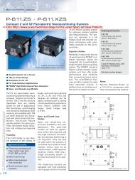
Motion Controllers, Drivers and Power <strong>Amplifier</strong>s<br />
for Piezoelectric NanoPositioning Systems<br />
<strong>PI</strong> offers the largest selection of digital and<br />
analog motion controllers and<br />
power amplifiers for piezo<br />
actuators worldwide.<br />
Electronics play a key role for maximum<br />
performance of piezoelectic<br />
NanoAutomation ® systems (such<br />
as PZT translators) and PZTdriven<br />
NanoPositioning systems<br />
(such as Flexure NanoPositioners<br />
or PZT tip/tilt platforms).<br />
Ultra-low-noise, high-stability servo-controllers<br />
and amplifiers are essential<br />
because even micro-volt changes<br />
of the control voltage are<br />
transformed into motion.<br />
For applications, where maximum throughput<br />
is crucial, <strong>PI</strong>'s digital feedforward<br />
techniques and highspeed<br />
interfaces speed up manufacturing<br />
processes.<br />
For dynamic high-power applications, our<br />
energy-recovery power amplifiers<br />
provide up to 2000 W of<br />
peak power.<br />
Quality control at GSG (<strong>PI</strong> subsidiary specializing<br />
in piezo control electronics, power amplifiers and<br />
motion control).<br />
Variety of digital and analog motion controllers and power amplifiers<br />
for piezoelectric positioning systems.<br />
Why can <strong>PI</strong> Provide Superior Piezo<br />
Controller Solutions?<br />
� More than 30 years experience designing piezoelectric<br />
positioning systems and control electronics<br />
� In-house PZT electronics design & manufacture ensure<br />
consistency and reliable quality<br />
� Largest variety of controllers (digital, analog, high-speed,<br />
high-power, OEM...)<br />
� State-of-the-art metrology lab: thermal, acoustic, seismic<br />
isolation for repeatable sub-nanometer measurements<br />
� State-of-the-art equipment for simulation, manufacturing<br />
and testing<br />
� Highly motivated team of engineers and physicists<br />
� In-house capacitive position sensor design & manufacture<br />
� Patented vibration-killing feedforward techniques for<br />
maximum throughput<br />
Patented InputShaping TM feedforward algorithm eliminates<br />
resonance-driven vibration of parts on and around the<br />
NanoPositioning system (top: off, bottom: on).<br />
This <strong>PI</strong> exclusive algorithm is an option on several of our<br />
digital controllers. It significantly increases throughput in<br />
automation processes, where every millisecond counts.<br />
6-1
6-2<br />
PZT Motion Controller Experience<br />
<strong>PI</strong> PZT Control Electronics Solutions<br />
� Custom designs<br />
� Single- and multi-channel, standard & OEM PZT controllers<br />
for low- & high-voltage PZTs<br />
� Digital & analog servo-control circuits, compatible<br />
with capacitive, LVDT & strain gauge position feedback<br />
sensors<br />
� Modular PZT controllers with high-speed parallel<br />
command interface, optionally opto-isolated for<br />
enhanced EMI Immunity<br />
� Ultra-fast fiber optic interfaces<br />
� Modular rackmount controllers with analog and digital<br />
interfaces<br />
� Unique multi-axis addressing capabilities for up to<br />
32 axes<br />
� Multi-channel, 32-bit digital controllers with highly<br />
responsive FiberLink, RS-232 & IEEE-488 interfaces<br />
� Advanced feedforward techniques for throughput<br />
enhancement<br />
� Patented vibration-cancelling InputShaping TM<br />
algorithm for highest throughput<br />
� 100 V and 1000 V PZT power amplifiers<br />
� Ultra-high-output power amplifiers featuring energy<br />
recovery techniques and 2000 W peak power<br />
Design phase of a new piezo controller.<br />
http://www.pi.ws<br />
info@pi.ws<br />
Group of Digital Controllers featuring the ultra-fast optical<br />
FiberLink interface and <strong>PI</strong>‘s exclusive Mach TM vibrationcancelling<br />
feedforward algorithm. (licensed by Convolve,<br />
Inc., www.convolve.com).<br />
Simulation tools help predict the performance of a new<br />
servo-control circuit even before the first prototype has<br />
been built.<br />
Group of standard and custom multi-axis digital<br />
NanoAutomation ® controllers with different<br />
interface options.
PZT Motion Controller Experience (cont.)<br />
Custom 6-channel NanoAutomation ® controller with<br />
ultra-fast digital parallel-port interface.<br />
Typical Applications of <strong>PI</strong> Piezo Controllers<br />
NanoCapture software for Digital Piezo Controllers features Bode<br />
plotting function to obtain a precise analysis of the<br />
NanoMechanisms connected to the controller.<br />
Digital NanoAutomation ® controller with ultra-fast<br />
fiber-optical interface<br />
PZT Actuators<br />
Custom DSP-based 7-channel capacitive-sensor controller with<br />
fiber-optic interface for communication with servo-controller.<br />
PZT Flexure NanoPositioners<br />
PZT Active Optics / Steering Mirrors<br />
Tutorial: Piezoelectrics...<br />
Capacitive Position Sensors<br />
PZT Control Electronics<br />
MicroPositioners / Hexapod Systems<br />
Photonics Alignment & Packaging Systems<br />
Motor Controllers<br />
Index<br />
� Mass storage (optical disk) mastering<br />
� Beam switching, alignment, steering<br />
� Photonics alignment & packaging<br />
� Interferometry (Fabry-Perot filters)<br />
� Vibration cancellation<br />
� Image stabilization<br />
� Image resolution enhancement<br />
� Laser beam steering and tracking<br />
� Adaptive optics<br />
� Scanning microscopy<br />
� Auto-focus systems<br />
� Nano-metrology<br />
� Wafer and mask positioning/alignment<br />
� Microlithography<br />
� Critical-dimension measurement<br />
� Fast tool servos<br />
� Out-of-roundness finishing<br />
� Smart structures / structural deformation<br />
http://www.pi.ws<br />
info@pi.ws<br />
6-3
6-4<br />
Qualifying a new NanoAutomation ® controller.<br />
Three-axis NanoCube TM piezo NanoAutomation ® stage and controller<br />
card with integrated optic metrology and automatic alignment<br />
functions. (for photonics alignment applications)<br />
Ultra-high-output power amplifier featuring energy recovery<br />
techniques and 2000 W peak power.<br />
http://www.pi.ws<br />
info@pi.ws<br />
Custom PCI-based digital PZT controller with<br />
high-speed fiber-optic interface and steering<br />
mirror unit.<br />
Block diagram showing the principle of the energy recovery concept.<br />
Custom controller with several compact NanoPositioning stages.
PZT Electronics: Motion Controllers and <strong>Amplifier</strong>s<br />
Contents<br />
Introduction . . . . . . . . . . . . . . . . . . . . . . . . . . . . . . . . . . . . . . . . . . . . . . . . . . . . . . . . . . . . . . . 6-1<br />
Motion Controllers and <strong>Amplifier</strong>s . . . . . . . . . . . . . . . . . . . . . . . . . . . . . . . . . . . . . . . . . . . . . 6-1<br />
Control Electronics Overview . . . . . . . . . . . . . . . . . . . . . . . . . . . . . . . . . . . . . . . . . . . . . . . . 6-2<br />
Why can <strong>PI</strong> provide superior control electronics solutions? . . . . . . . . . . . . . . . . . . . . . . . . . 6-3<br />
Table of Contents . . . . . . . . . . . . . . . . . . . . . . . . . . . . . . . . . . . . . . . . . . . . . . . . . . . . . . . . . . . 6-5<br />
Selection Guide . . . . . . . . . . . . . . . . . . . . . . . . . . . . . . . . . . . . . . . . . . . . . . . . . . . . . . . . . . . . 6-6<br />
E-710 High-Speed Digital NanoAutomation PZT Controllers . . . . . . . . . . . . . . . . . . . . . . . 6-8<br />
NanoCapture Software for E-710 Digital PZT Controllers . . . . . . . . . . . . . . . . . . . . . . . . . . . 6-9<br />
E-612, E-661 High-Speed NanoAutomation ® Controllers . . . . . . . . . . . . . . . . . . . . . . . . . . 6-10<br />
E-750 High-Speed Digital PZT Controller . . . . . . . . . . . . . . . . . . . . . . . . . . . . . . . . . . . . . . . 6-12<br />
E-760 <strong>LVPZT</strong> <strong>Amplifier</strong>/Controller Card with Automatic Alignment Functions . . . . . . . . 6-14<br />
E-664 <strong>LVPZT</strong> <strong>Amplifier</strong> & Position Servo-Controller, 3 Channels . . . . . . . . . . . . . . . . . . . 6-15<br />
E-665 <strong>LVPZT</strong> <strong>Amplifier</strong> & Position Servo-Controller . . . . . . . . . . . . . . . . . . . . . . . . . . . . . . 6-16<br />
E-610 <strong>LVPZT</strong> <strong>Amplifier</strong> & Position Servo-Controller <strong>Module</strong>s, OEM Version . . . . . . . . . . 6-18<br />
E-500, E-501 Modular PZT Control Systems (HVPZT & <strong>LVPZT</strong>) . . . . . . . . . . . . . . . . . . . . .6-20<br />
E-500, E-501 System Configuration . . . . . . . . . . . . . . . . . . . . . . . . . . . . . . . . . . . . . . . . . . . 6-21<br />
E-500, E-501 <strong>Module</strong> Survey & Ordering Examples . . . . . . . . . . . . . . . . . . . . . . . . . . . . . . 6-22<br />
E-470, E-471, E-472, E-420 High-Power Modular HVPZT <strong>Amplifier</strong>s/Controllers . . . . . . . 6-24<br />
E-480 High-Power HVPZT <strong>Amplifier</strong>/Controller With Energy Recovery . . . . . . . . . . . . . . 6-26<br />
E-463 HVPZT <strong>Amplifier</strong>, 3 Channels . . . . . . . . . . . . . . . . . . . . . . . . . . . . . . . . . . . . . . . . . . . 6-28<br />
E-663 <strong>LVPZT</strong> <strong>Amplifier</strong>, 3 Channels . . . . . . . . . . . . . . . . . . . . . . . . . . . . . . . . . . . . . . . . . . . 6-29<br />
E-461 HVPZT <strong>Amplifier</strong>, Standard and OEM <strong>Module</strong> . . . . . . . . . . . . . . . . . . . . . . . . . . . . . 6-30<br />
E-660 <strong>LVPZT</strong> <strong>Amplifier</strong>, Standard and OEM Version . . . . . . . . . . . . . . . . . . . . . . . . . . . . . . 6-31<br />
E-650 <strong>LVPZT</strong> <strong>Amplifier</strong> for Multilayer Bender Actuators, Standard and OEM Version . . 6-32<br />
E-503 <strong>LVPZT</strong> <strong>Amplifier</strong> <strong>Module</strong>, 3 Channels . . . . . . . . . . . . . . . . . . . . . . . . . . . . . . . . . . . . 6-33<br />
E-505 <strong>LVPZT</strong> <strong>Amplifier</strong> <strong>Module</strong> . . . . . . . . . . . . . . . . . . . . . . . . . . . . . . . . . . . . . . . . . . . . . . . 6-34<br />
E-507 and E-507.OE HVPZT <strong>Amplifier</strong> <strong>Module</strong> . . . . . . . . . . . . . . . . . . . . . . . . . . . . . . . . . . 6-35<br />
E-509 Sensor & Position Servo-Control <strong>Module</strong>s for PZTs . . . . . . . . . . . . . . . . . . . . . . . . 6-36<br />
E-516 Computer Interface & Display <strong>Module</strong> . . . . . . . . . . . . . . . . . . . . . . . . . . . . . . . . . . . 6-37<br />
E-515 Display <strong>Module</strong>s . . . . . . . . . . . . . . . . . . . . . . . . . . . . . . . . . . . . . . . . . . . . . . . . . . . . . 6-38<br />
E-530 Power Supply for E-500 Systems . . . . . . . . . . . . . . . . . . . . . . . . . . . . . . . . . . . . . . . . 6-39<br />
E-531 Power Supply for E-501 Systems . . . . . . . . . . . . . . . . . . . . . . . . . . . . . . . . . . . . . . . . 6-39<br />
Typical <strong>PI</strong> PZT <strong>Amplifier</strong> & Position Servo-Controller . . . . . . . . . . . . . . . . . . . . . . . . . . . . 6-40<br />
Power Requirements for PZT Operation . . . . . . . . . . . . . . . . . . . . . . . . . . . . . . . . . . . . . . . 6-40<br />
Position Servo-Controller Calibration Information . . . . . . . . . . . . . . . . . . . . . . . . . . . . . . . 6-41<br />
Accessories . . . . . . . . . . . . . . . . . . . . . . . . . . . . . . . . . . . . . . . . . . . . . . . . . . . . . . . . . . . . . . . 6-42<br />
E-115 LVDT Position Sensors . . . . . . . . . . . . . . . . . . . . . . . . . . . . . . . . . . . . . . . . . . . . . . . 6-42<br />
Cables, Connectors & Adapter for <strong>LVPZT</strong> Translators . . . . . . . . . . . . . . . . . . . . . . . . . . . . . 6-43<br />
Cables, Connectors & Adapter for HVPZT Translators . . . . . . . . . . . . . . . . . . . . . . . . . . . . . 6-44<br />
Sensor Extension Cables . . . . . . . . . . . . . . . . . . . . . . . . . . . . . . . . . . . . . . . . . . . . . . . . . . . 6-45<br />
Recommended <strong>Amplifier</strong>/Controller Reference List . . . . . . . . . . . . . . . . . . . . . . . . . . . . . 6-46<br />
Additional products see page 6-47 ff<br />
Additional products see page 6-47 ff<br />
6-5
PZT Electronics Selection Guide<br />
Models Function Output Peak Output Channels Display Optional Installable Case Page<br />
Voltage Power (Channels x Computer <strong>Module</strong>s /(Height/Width<br />
[V] [W] Digits) Interface Notes Units)<br />
E-501.10 NanoAutomation ® n/a n/a 1 to 4 n/a see E-612.C0 E-612.C0 9.5” Bench-top 6-10<br />
Controller Chassis 3H/42T<br />
E-612.C0 <strong>LVPZT</strong> High-Speed -20 to 120 8 1 n/a Integrated n/a Euro-board 6-10<br />
NanoAutomation ® high-speed parallel<br />
Controller Board port, opto-isolated<br />
E-661.CP <strong>LVPZT</strong> High-Speed -20 to 120 8 1 n/a Integrated high-speed n/a Bench-top 6-10<br />
NanoAutomation parallel port, opto-isolated<br />
Controller<br />
E-710 <strong>LVPZT</strong> Digital -20 to 120 25 3, 4, 6 n/a Integrated RS-232 n/a 19” Rackmount, 6-8<br />
Piezo Controller and IEEE 488 2H/84T<br />
E-750.CP <strong>LVPZT</strong> Digital -20 to 120 10 1 n/a Integrated RS-232, n/a Bench-top 6-12<br />
Piezo Controller Optional Fiber Link,<br />
and Parallel Port<br />
E-610.00 <strong>LVPZT</strong> <strong>Amplifier</strong> -20 to 120 14 1 n/a RS-232 n/a Euro-board 6-18<br />
<strong>Module</strong>, OEM<br />
E-610.S0 <strong>LVPZT</strong> <strong>Amplifier</strong>/ -20 to 120 14 1 n/a RS-232 n/a Euro-board 6-18<br />
E-610.L0 Position Controller<br />
E-610.C0 <strong>Module</strong>, OEM<br />
E-662.xx <strong>LVPZT</strong> <strong>Amplifier</strong>/ -20 to 120 36 1 2x3 1 / 2 , RS-232 n/a Bench-top 2H/ 6-16<br />
Position Controller LED 42T<br />
E-664.00 NanoCube Controller -20 to 120 3 x 14 3 3x3 1 / 2 , LED Integrated servo- n/a Bench-top 2H/42T 6-15<br />
controller designed for<br />
NanoCube systems<br />
E-760 NanoCube -20 to 120 3 x 9 3 PC bus (ISA) Integrated servo-. n/a PC board 6-14<br />
Controller Card controller designed for<br />
NanoCube systems<br />
E-463.00 HVPZT <strong>Amplifier</strong> 0 to -1500 3 x 5 3 3x3 1 / 2 , LED n/a n/a Bench-top 2H/42T 6-28<br />
E-663.00 <strong>LVPZT</strong> <strong>Amplifier</strong> -20 to 120 3 x 14 3 3x3 1 / 2 , LED n/a n/a Bench-top 2H/42T 6-29<br />
E-500.00 Chassis for PZT <strong>Amplifier</strong>/ n/a n/a 1, 2, 3 Optional IEEE 488 & E-503, E-505, 19” Rackmount 6-20<br />
Position Servo-Controller E-515, RS-232 E-507, E-509, 3H/84T<br />
E-516 E-515, E-516<br />
E-501.00 Chassis for PZT <strong>Amplifier</strong>/ n/a n/a 1, 3 Optional IEEE 488 E-503, E-505, 9.5” Bench-top 6-20<br />
Position Servo-Controller E-515, & RS-232 E-507, E-509, 3H/42T<br />
E-516 E-515, E-516<br />
E-420.00 HVPZT <strong>Amplifier</strong> <strong>Module</strong> -3 to -1100 500 1 n/a n/a n/a 9.5” <strong>Module</strong> 6-24<br />
& bipolar<br />
E-470.00 HVPZT <strong>Amplifier</strong> -3 to -1100 500 1 n/a n/a n/a 9.5” Bench-top 6-24<br />
& bipolar 3H/42T<br />
6-6<br />
Additional products see page 6-47 ff<br />
http://www.pi.ws<br />
info@pi.ws
Models Function Output Peak Output Channels Display Optional Installable Case Page<br />
Voltage Power (Channels x Computer <strong>Module</strong>s /(Height/Width<br />
[V] [W] Digits) Interface Notes Units)<br />
E-472.00 HVPZT -3 to -1100 500 2 n/a n/a n/a 19” Rackmount 6-24<br />
<strong>Amplifier</strong> & bipolar 3H/84T<br />
E-471.00 HVPZT -3 to -1100 500 1 Optional IEEE 488 E-509, E-515, 19” Rackmount 6-24<br />
<strong>Amplifier</strong> & bipolar E-515, E-516 & RS-232 E-516 3H/84T<br />
E-480.00 HVPZT 0 to -1000 2000 1 Optional IEEE 488 E-509, E-515, 19” Rackmount 6-26<br />
High-Power & bipolar E-515, E-516 & RS-232 E-516 3H/84T<br />
<strong>Amplifier</strong><br />
E-503.00 <strong>LVPZT</strong> -20 to 120 3 x 14 3 n/a n/a n/a 19” <strong>Module</strong>, 6-33<br />
<strong>Amplifier</strong> <strong>Module</strong> 14T<br />
E-505.00 <strong>LVPZT</strong> -20 to 120 200 1 n/a n/a n/a 19” <strong>Module</strong>, 6-34<br />
<strong>Amplifier</strong> <strong>Module</strong> 14T<br />
E-507.00 HVPZT -3 to -1100 50 1 n/a n/a n/a 19” <strong>Module</strong>, 6-35<br />
<strong>Amplifier</strong> <strong>Module</strong> & bipolar 14T<br />
E-509.xx Position Servo- n/a n/a 1, 2, 3 n/a n/a n/a 19” <strong>Module</strong>, 6-36<br />
Controller/ 7T<br />
Sensor <strong>Module</strong><br />
E-516.i3 D/A Converter / n/a n/a 3 4 1 / 2 , LCD Standard n/a 19” <strong>Module</strong>, 6-37<br />
Display / IEEE & IEEE 488 21T<br />
RS-232 Interface <strong>Module</strong> & RS-232<br />
E-515.0x Display <strong>Module</strong> n/a n/a 1, 3 1 & 3 x 3 1 / 2 LED n/a n/a 19” <strong>Module</strong>, 21T 6-38<br />
E-461.00 HVPZT <strong>Amplifier</strong> -10 to -1000 0.5 1 n/a n/a n/a Bench-top / 6-30<br />
E-461.OE HVPZT <strong>Amplifier</strong>, PCB module<br />
OEM <strong>Module</strong><br />
E-660.00 <strong>LVPZT</strong> <strong>Amplifier</strong> 5 to 100 2 1 n/a n/a n/a Bench-top / 6-31<br />
E-660.OE <strong>LVPZT</strong> <strong>Amplifier</strong>, PCB module<br />
OEM <strong>Module</strong><br />
E-650.00 <strong>LVPZT</strong> <strong>Amplifier</strong> 0 to 60 18 1 3 1 / 2 , LCD n/a n/a Bench-top / 6-32<br />
E-650.OE <strong>LVPZT</strong> <strong>Amplifier</strong>, 8 n/a PCB module<br />
OEM <strong>Module</strong><br />
E-530.00 Power Supply n/a n/a n/a n/a n/a n/a <strong>Module</strong> 6-39<br />
E-531.00 <strong>Module</strong><br />
n/a: not applicable<br />
Bench-Top & Rackmount Controller Dimensions<br />
Chassis W H D Units<br />
2H/42T 235 103 288 mm<br />
3H/42T 235 158 288 mm<br />
3H/84T 450 158 288 mm<br />
2H/84T 450 105 290 mm<br />
H: Height Units T: Width Units<br />
Dimensional drawing for bench-top and<br />
rackmount controllers<br />
6-7
PZT Electronics: Motion Controllers and <strong>Amplifier</strong>s<br />
Contents<br />
Introduction . . . . . . . . . . . . . . . . . . . . . . . . . . . . . . . . . . . . . . . . . . . . . . . . . . . . . . . . . . . . . . . 6-1<br />
Motion Controllers and <strong>Amplifier</strong>s . . . . . . . . . . . . . . . . . . . . . . . . . . . . . . . . . . . . . . . . . . . . . 6-1<br />
Control Electronics Overview . . . . . . . . . . . . . . . . . . . . . . . . . . . . . . . . . . . . . . . . . . . . . . . . 6-2<br />
Why can <strong>PI</strong> provide superior control electronics solutions? . . . . . . . . . . . . . . . . . . . . . . . . . 6-3<br />
Table of Contents . . . . . . . . . . . . . . . . . . . . . . . . . . . . . . . . . . . . . . . . . . . . . . . . . . . . . . . . . . . 6-5<br />
Selection Guide . . . . . . . . . . . . . . . . . . . . . . . . . . . . . . . . . . . . . . . . . . . . . . . . . . . . . . . . . . . . 6-6<br />
E-710 High-Speed Digital NanoAutomation PZT Controllers . . . . . . . . . . . . . . . . . . . . . . . 6-8<br />
NanoCapture Software for E-710 Digital PZT Controllers . . . . . . . . . . . . . . . . . . . . . . . . . . . 6-9<br />
E-612, E-661 High-Speed NanoAutomation ® Controllers . . . . . . . . . . . . . . . . . . . . . . . . . . 6-10<br />
E-750 High-Speed Digital PZT Controller . . . . . . . . . . . . . . . . . . . . . . . . . . . . . . . . . . . . . . . 6-12<br />
E-760 <strong>LVPZT</strong> <strong>Amplifier</strong>/Controller Card with Automatic Alignment Functions . . . . . . . . 6-14<br />
E-664 <strong>LVPZT</strong> <strong>Amplifier</strong> & Position Servo-Controller, 3 Channels . . . . . . . . . . . . . . . . . . . 6-15<br />
E-662 <strong>LVPZT</strong> <strong>Amplifier</strong> & Position Servo-Controller . . . . . . . . . . . . . . . . . . . . . . . . . . . . . . 6-16<br />
E-610 <strong>LVPZT</strong> <strong>Amplifier</strong> & Position Servo-Controller <strong>Module</strong>s, OEM Version . . . . . . . . . . 6-18<br />
E-500, E-501 Modular PZT Control Systems (HVPZT & <strong>LVPZT</strong>) . . . . . . . . . . . . . . . . . . . . .6-20<br />
E-500, E-501 System Configuration . . . . . . . . . . . . . . . . . . . . . . . . . . . . . . . . . . . . . . . . . . . 6-21<br />
E-500, E-501 <strong>Module</strong> Survey & Ordering Examples . . . . . . . . . . . . . . . . . . . . . . . . . . . . . . 6-22<br />
E-470, E-471, E-472, E-420 High-Power Modular HVPZT <strong>Amplifier</strong>s/Controllers . . . . . . . 6-24<br />
E-480 High-Power HVPZT <strong>Amplifier</strong>/Controller With Energy Recovery . . . . . . . . . . . . . . 6-26<br />
E-463 HVPZT <strong>Amplifier</strong>, 3 Channels . . . . . . . . . . . . . . . . . . . . . . . . . . . . . . . . . . . . . . . . . . . 6-28<br />
E-663 <strong>LVPZT</strong> <strong>Amplifier</strong>, 3 Channels . . . . . . . . . . . . . . . . . . . . . . . . . . . . . . . . . . . . . . . . . . . 6-29<br />
E-461 HVPZT <strong>Amplifier</strong>, Standard and OEM <strong>Module</strong> . . . . . . . . . . . . . . . . . . . . . . . . . . . . . 6-30<br />
E-660 <strong>LVPZT</strong> <strong>Amplifier</strong>, Standard and OEM Version . . . . . . . . . . . . . . . . . . . . . . . . . . . . . . 6-31<br />
E-650 <strong>LVPZT</strong> <strong>Amplifier</strong> for Multilayer Bender Actuators, Standard and OEM Version . . 6-32<br />
E-503 <strong>LVPZT</strong> <strong>Amplifier</strong> <strong>Module</strong>, 3 Channels . . . . . . . . . . . . . . . . . . . . . . . . . . . . . . . . . . . . 6-33<br />
E-505 <strong>LVPZT</strong> <strong>Amplifier</strong> <strong>Module</strong> . . . . . . . . . . . . . . . . . . . . . . . . . . . . . . . . . . . . . . . . . . . . . . . 6-34<br />
E-507 and E-507.OE HVPZT <strong>Amplifier</strong> <strong>Module</strong> . . . . . . . . . . . . . . . . . . . . . . . . . . . . . . . . . . 6-35<br />
E-509 Sensor & Position Servo-Control <strong>Module</strong>s for PZTs . . . . . . . . . . . . . . . . . . . . . . . . 6-36<br />
E-516 Computer Interface & Display <strong>Module</strong> . . . . . . . . . . . . . . . . . . . . . . . . . . . . . . . . . . . 6-37<br />
E-515 Display <strong>Module</strong>s . . . . . . . . . . . . . . . . . . . . . . . . . . . . . . . . . . . . . . . . . . . . . . . . . . . . . 6-38<br />
E-530 Power Supply for E-500 Systems . . . . . . . . . . . . . . . . . . . . . . . . . . . . . . . . . . . . . . . . 6-39<br />
E-531 Power Supply for E-501 Systems . . . . . . . . . . . . . . . . . . . . . . . . . . . . . . . . . . . . . . . . 6-39<br />
Typical <strong>PI</strong> PZT <strong>Amplifier</strong> & Position Servo-Controller . . . . . . . . . . . . . . . . . . . . . . . . . . . . 6-40<br />
Power Requirements for PZT Operation . . . . . . . . . . . . . . . . . . . . . . . . . . . . . . . . . . . . . . . 6-40<br />
Position Servo-Controller Calibration Information . . . . . . . . . . . . . . . . . . . . . . . . . . . . . . . 6-41<br />
Accessories . . . . . . . . . . . . . . . . . . . . . . . . . . . . . . . . . . . . . . . . . . . . . . . . . . . . . . . . . . . . . . . 6-42<br />
E-115 LVDT Position Sensors . . . . . . . . . . . . . . . . . . . . . . . . . . . . . . . . . . . . . . . . . . . . . . . 6-42<br />
Cables, Connectors & Adapter for <strong>LVPZT</strong> Translators . . . . . . . . . . . . . . . . . . . . . . . . . . . . . 6-43<br />
Cables, Connectors & Adapter for HVPZT Translators . . . . . . . . . . . . . . . . . . . . . . . . . . . . . 6-44<br />
Sensor Extension Cables . . . . . . . . . . . . . . . . . . . . . . . . . . . . . . . . . . . . . . . . . . . . . . . . . . . 6-45<br />
Recommended <strong>Amplifier</strong>/Controller Reference List . . . . . . . . . . . . . . . . . . . . . . . . . . . . . 6-46<br />
6-5
PZT Electronics Selection Guide<br />
Models Function Output Peak Output Channels Display Optional Installable Case Page<br />
Voltage Power (Channels x Computer <strong>Module</strong>s /(Height/Width<br />
[V] [W] Digits) Interface Notes Units)<br />
E-501.10 NanoAutomation ® n/a n/a 1 to 4 n/a see E-612.C0 E-612.C0 9.5” Bench-top 6-10<br />
Controller Chassis 3H/42T<br />
E-612.C0 <strong>LVPZT</strong> High-Speed -20 to 120 8 1 n/a Integrated n/a Euro-board 6-10<br />
NanoAutomation ® high-speed parallel<br />
Controller Board port, opto-isolated<br />
E-661.CP <strong>LVPZT</strong> High-Speed -20 to 120 8 1 n/a Integrated high-speed n/a Bench-top 6-10<br />
NanoAutomation parallel port, opto-isolated<br />
Controller<br />
E-710 <strong>LVPZT</strong> Digital -20 to 120 25 3, 4, 6 n/a Integrated RS-232 n/a 19” Rackmount, 6-8<br />
Piezo Controller and IEEE 488 2H/84T<br />
E-750.CP <strong>LVPZT</strong> Digital -20 to 120 10 1 n/a Integrated RS-232, n/a Bench-top 6-12<br />
Piezo Controller Optional Fiber Link,<br />
and Parallel Port<br />
E-610.00 <strong>LVPZT</strong> <strong>Amplifier</strong> -20 to 120 14 1 n/a RS-232 n/a Euro-board 6-18<br />
<strong>Module</strong>, OEM<br />
E-610.S0 <strong>LVPZT</strong> <strong>Amplifier</strong>/ -20 to 120 14 1 n/a RS-232 n/a Euro-board 6-18<br />
E-610.L0 Position Controller<br />
E-610.C0 <strong>Module</strong>, OEM<br />
E-662.xx <strong>LVPZT</strong> <strong>Amplifier</strong>/ -20 to 120 36 1 2x3 1 / 2 , RS-232 n/a Bench-top 2H/ 6-16<br />
Position Controller LED 42T<br />
E-664.00 NanoCube Controller -20 to 120 3 x 14 3 3x3 1 / 2 , LED Integrated servo- n/a Bench-top 2H/42T 6-15<br />
controller designed for<br />
NanoCube systems<br />
E-760 NanoCube -20 to 120 3 x 9 3 PC bus (ISA) Integrated servo-. n/a PC board 6-14<br />
Controller Card controller designed for<br />
NanoCube systems<br />
E-463.00 HVPZT <strong>Amplifier</strong> 0 to -1500 3 x 5 3 3x3 1 / 2 , LED n/a n/a Bench-top 2H/42T 6-28<br />
E-663.00 <strong>LVPZT</strong> <strong>Amplifier</strong> -20 to 120 3 x 14 3 3x3 1 / 2 , LED n/a n/a Bench-top 2H/42T 6-29<br />
E-500.00 Chassis for PZT <strong>Amplifier</strong>/ n/a n/a 1, 2, 3 Optional IEEE 488 & E-503, E-505, 19” Rackmount 6-20<br />
Position Servo-Controller E-515, RS-232 E-507, E-509, 3H/84T<br />
E-516 E-515, E-516<br />
E-501.00 Chassis for PZT <strong>Amplifier</strong>/ n/a n/a 1, 3 Optional IEEE 488 E-503, E-505, 9.5” Bench-top 6-20<br />
Position Servo-Controller E-515, & RS-232 E-507, E-509, 3H/42T<br />
E-516 E-515, E-516<br />
E-420.00 HVPZT <strong>Amplifier</strong> <strong>Module</strong> -3 to -1100 500 1 n/a n/a n/a 9.5” <strong>Module</strong> 6-24<br />
& bipolar<br />
E-470.00 HVPZT <strong>Amplifier</strong> -3 to -1100 500 1 n/a n/a n/a 9.5” Bench-top 6-24<br />
& bipolar 3H/42T<br />
6-6<br />
http://www.pi.ws<br />
info@pi.ws
Models Function Output Peak Output Channels Display Optional Installable Case Page<br />
Voltage Power (Channels x Computer <strong>Module</strong>s /(Height/Width<br />
[V] [W] Digits) Interface Notes Units)<br />
E-472.00 HVPZT -3 to -1100 500 2 n/a n/a n/a 19” Rackmount 6-24<br />
<strong>Amplifier</strong> & bipolar 3H/84T<br />
E-471.00 HVPZT -3 to -1100 500 1 Optional IEEE 488 E-509, E-515, 19” Rackmount 6-24<br />
<strong>Amplifier</strong> & bipolar E-515, E-516 & RS-232 E-516 3H/84T<br />
E-480.00 HVPZT 0 to -1000 2000 1 Optional IEEE 488 E-509, E-515, 19” Rackmount 6-26<br />
High-Power & bipolar E-515, E-516 & RS-232 E-516 3H/84T<br />
<strong>Amplifier</strong><br />
E-503.00 <strong>LVPZT</strong> -20 to 120 3 x 14 3 n/a n/a n/a 19” <strong>Module</strong>, 6-33<br />
<strong>Amplifier</strong> <strong>Module</strong> 14T<br />
E-505.00 <strong>LVPZT</strong> -20 to 120 200 1 n/a n/a n/a 19” <strong>Module</strong>, 6-34<br />
<strong>Amplifier</strong> <strong>Module</strong> 14T<br />
E-507.00 HVPZT -3 to -1100 50 1 n/a n/a n/a 19” <strong>Module</strong>, 6-35<br />
<strong>Amplifier</strong> <strong>Module</strong> & bipolar 14T<br />
E-509.xx Position Servo- n/a n/a 1, 2, 3 n/a n/a n/a 19” <strong>Module</strong>, 6-36<br />
Controller/ 7T<br />
Sensor <strong>Module</strong><br />
E-516.i3 D/A Converter / n/a n/a 3 4 1 / 2 , LCD Standard n/a 19” <strong>Module</strong>, 6-37<br />
Display / IEEE & IEEE 488 21T<br />
RS-232 Interface <strong>Module</strong> & RS-232<br />
E-515.0x Display <strong>Module</strong> n/a n/a 1, 3 1 & 3 x 3 1 / 2 LED n/a n/a 19” <strong>Module</strong>, 21T 6-38<br />
E-461.00 HVPZT <strong>Amplifier</strong> -10 to -1000 0.5 1 n/a n/a n/a Bench-top / 6-30<br />
E-461.OE HVPZT <strong>Amplifier</strong>, PCB module<br />
OEM <strong>Module</strong><br />
E-660.00 <strong>LVPZT</strong> <strong>Amplifier</strong> 5 to 100 2 1 n/a n/a n/a Bench-top / 6-31<br />
E-660.OE <strong>LVPZT</strong> <strong>Amplifier</strong>, PCB module<br />
OEM <strong>Module</strong><br />
E-650.00 <strong>LVPZT</strong> <strong>Amplifier</strong> 0 to 60 18 1 3 1 / 2 , LCD n/a n/a Bench-top / 6-32<br />
E-650.OE <strong>LVPZT</strong> <strong>Amplifier</strong>, 8 n/a PCB module<br />
OEM <strong>Module</strong><br />
E-530.00 Power Supply n/a n/a n/a n/a n/a n/a <strong>Module</strong> 6-39<br />
E-531.00 <strong>Module</strong><br />
n/a: not applicable<br />
Bench-Top & Rackmount Controller Dimensions<br />
Chassis W H D Units<br />
2H/42T 235 103 288 mm<br />
3H/42T 235 158 288 mm<br />
3H/84T 450 158 288 mm<br />
2H/84T 450 105 290 mm<br />
H: Height Units T: Width Units<br />
Dimensional drawing for bench-top and<br />
rackmount controllers<br />
6-7
Ordering<br />
Information<br />
6-8<br />
E-710<br />
E-710.3CD<br />
Digital Piezo Controller, 3 Axes,<br />
Sub-D-Special Connector, RS-232 &<br />
IEEE-488 Interface<br />
E-710.4CL<br />
Digital Piezo Controller, 4 Axes, Lemo<br />
Connectors, RS-232 & IEEE 488 Interface<br />
E-710.4CD<br />
Digital Piezo Controller, 4 Axes, Sub-D<br />
Connector, RS-232 & IEEE 488 Interface<br />
E-710.P3D<br />
Digital Piezo Controller, 3 + 1 Axes,<br />
Sub-D-Connectors, RS-232, IEEE-488<br />
& High-Speed <strong>PI</strong>O Interface<br />
E-710.P4L<br />
Digital Piezo Controller, 4 Axes,<br />
LEMO Connectors, RS-232, IEEE 488<br />
& High-Speed <strong>PI</strong>O Interface<br />
E-710.P4D<br />
Digital Piezo Controller, 4 Axes,<br />
Sub-D Connectors, RS-232, IEEE 488<br />
& High-Speed <strong>PI</strong>O Interface<br />
E-710.6CD<br />
Digital Piezo Controller, 6 Axes,<br />
Sub-D-Special Connectors RS-232<br />
& IEEE 488 Interface<br />
Options<br />
E-710.SCN<br />
Dynamic Digital Linearization<br />
Upgrade<br />
E-710.3x3<br />
Extension Cable Piezo NanoPositioning<br />
Stage / E-710.3CD Controller, 3 m<br />
E-710.3x5<br />
Extension Cable Piezo NanoPositioning<br />
Stage / E-710.3CD Controller, 5 m<br />
E-710.1x3<br />
Extension Cable 3m, E-750 / E-710<br />
to Piezo Flexure Stage, 1 Channel Sub-D<br />
High-Speed Digital NanoAutomation ®<br />
Piezo Controllers<br />
E-710.6CD 6-axis digital piezo controller<br />
shown with custom Super Invar 6-DOF<br />
piezo flexure NanoPositioning stage.<br />
� For Piezo NanoPositioners<br />
with Capacitive Feedback<br />
Sensors<br />
� 3-, 4- & 6-Channel Versions<br />
� 32-Bit Digital Filters<br />
� Polynomial Linearization<br />
� Coordinate Transformation<br />
for Parallel Kinematics /<br />
Parallel Metrology Systems<br />
� Optional Dynamic Digital<br />
Linearization (Firmware<br />
Option) Improves<br />
Scanning Linearity<br />
� AutoCalibrate Function<br />
for Easy Controller /<br />
Stage Interchangeability<br />
� Fast RS-232 and IEEE 488<br />
Interfaces<br />
� Optional High-Speed<br />
Parallel Port Interface<br />
� Extensive Software<br />
Support<br />
E-710 digital piezo controllers/<br />
drivers are the most advanced<br />
and flexible controllers for<br />
piezo nanopositioning and<br />
scanning stages on the market.<br />
Based on powerful 32-bit<br />
DSPs (digital signal processor)<br />
they control up to six-degrees<br />
of freedom with integrated<br />
power amplifiers for multilayer<br />
PZT drives (-20 to 110 V) and<br />
http://www.pi.ws<br />
info@pi.ws<br />
signal conditioning electronics<br />
for two-plate capacitive position<br />
sensors. E-710 controllers<br />
represent a major advance<br />
over conventional multi-axis<br />
controllers because the sensor<br />
and output channels of two or<br />
more axes can participate in an<br />
internal coordinate transformation<br />
for multi-axis parallel-kinematics<br />
positioning systems with<br />
parallel-motion metrology, e.g.<br />
the P-500 series on page 2-32.<br />
Parallel Motion Metrology<br />
“Sees” all Controlled<br />
Degrees of Freedom<br />
Simultaneously<br />
Parallel-kinematics nanopositioning<br />
systems with parallelmetrology<br />
position feedback<br />
are superior to stacked or nested<br />
multi-axis positioning systems.<br />
They allow active trajectory<br />
control, automatic crosstalk<br />
and runout compensation<br />
and provide direct, non-contacting<br />
position information,<br />
measuring motion exactly<br />
where it matters (rather than<br />
measuring the strain in the<br />
drive system, a technique<br />
common in lower-precision<br />
positioning systems relying on<br />
the feedback of piezo resistive<br />
sensors).<br />
Integrated Linearization<br />
Systems<br />
E-710-controlled nanopositioning<br />
systems boast outstanding<br />
linearity, achieved by <strong>PI</strong>’s proprietary<br />
ILS (Integrated Linearization<br />
System) and additional<br />
digital polynomial linearization.<br />
The ILS, part of the E-710’s<br />
capacitive position sensor signal<br />
conditioning circuitry, compensates<br />
for influences caused<br />
by non-parallelism of the sensor<br />
plates. The digital polynomial<br />
linearization is calibrated<br />
for each individual nanopositioning<br />
system and can<br />
improve linearity to 0.001%<br />
over the full travel range.<br />
Custom Designs<br />
for Volume Buyers E-710 data acquisition and analysis functions (Bode plots, etc.) help optimize<br />
performance of NanoPositioning systems.
System Analysis—Advanced<br />
Software Tools<br />
The E-710 comes with the<br />
NanoCapture software featuring<br />
advanced functions for<br />
measuring-system response,<br />
step-and-settle and Bode plots.<br />
All positioning commands use<br />
standard units such as micrometers<br />
or microradians, for easy<br />
programming. In addition, all<br />
control parameters are nonvolatile,<br />
user-accessible and<br />
can be easily modified and<br />
optimized. Fully programmable<br />
low-pass & notch filters round<br />
out the E-710.<br />
Integrated Wave<br />
Generator & Look-up Table<br />
The implementation of a wave<br />
generator for all E-710 models<br />
allows the synchronous driving<br />
of several axes with a mathematical<br />
function or with a userdefined<br />
random signal stored<br />
in a lookup table containing<br />
65,535 points. Programmable<br />
trigger inputs and outputs facilitate<br />
synchronization with<br />
external events.<br />
Communication / Interfaces<br />
E-710 controllers are equipped<br />
with fast RS-232 and IEEE 488<br />
interfaces. The optional parallel<br />
port I/O (<strong>PI</strong>O) interface allows<br />
the fastest possible position<br />
setting/reading (20,000 positions<br />
per second bypassing the<br />
command parser).<br />
Dynamic Digital Linearization<br />
Improves Scanning<br />
Linearity up to 3 Orders of<br />
Magnitude<br />
Control theory predicts that<br />
conventional <strong>PI</strong>D (proportional<br />
Extensive<br />
Software Support<br />
The E-710 controller comes with a<br />
variety of software tools as well as<br />
LabView TM drivers and DLL’s for easy<br />
setup, system analysis and integration.<br />
Dynamic Digital Linearization<br />
integral derivative) servo motion<br />
controllers exhibit phase<br />
lag and tracking errors in<br />
dynamic operation (due to the<br />
fact that a <strong>PI</strong>D controller needs<br />
to see an error first before a<br />
reaction occurs, and also due<br />
to the nonlinear nature of PZT<br />
material). Depending on the<br />
controller settings and specs<br />
of the nanopositioning system<br />
driven, tracking errors (the difference<br />
between the commanded<br />
position and actual<br />
position) can reach double-digit<br />
percentage values even at<br />
Triangular scanning signal at 312 Hz. There is a significant<br />
difference (2.6 µm max.) between target and real position with<br />
the conventional <strong>PI</strong>D motion controller.<br />
Elliptical scan in a laser micro-drilling application with XY<br />
piezo scanning stage, conventional controller, 60 msec/rev.<br />
The outer curve ellipse describes the target position, the inner<br />
ellipse shows the actual motion at the stage.<br />
moderate scanning rates.<br />
Consequently, scanning stages<br />
often cannot be driven at the<br />
desired rates, or the acquired<br />
data has poor linearity.<br />
The new E-710.SCN Dynamic<br />
Digital Linearization upgrade<br />
(standard for the E-710.6CD<br />
6-axis controller, optional for<br />
the 3- and 4-channel versions)<br />
solves this problem. This <strong>PI</strong>exclusive<br />
technology is a<br />
breakthrough for scanning<br />
applications, reducing phase<br />
lag and nonlinearity to indiscernible<br />
levels, even with high-<br />
PZT Actuators<br />
PZT Flexure NanoPositioners<br />
PZT Active Optics / Steering Mirrors<br />
Tutorial: Piezoelectrics...<br />
Capacitive Position Sensors<br />
PZT Control Electronics<br />
MicroPositioners / Hexapod Systems<br />
Photonics Alignment & Packaging Systems<br />
Motor Controllers<br />
Index<br />
http://www.pi.ws<br />
info@pi.ws<br />
frequency dynamic actuation<br />
under load. The effect is an<br />
improvement in linearity (and<br />
usable bandwidth) of up to<br />
three orders of magnitude,<br />
resulting in significantly increased<br />
throughput. Dynamic<br />
Digital Linearization works<br />
both in single-axis and multiaxis<br />
applications (see graphs).<br />
Triangular scanning signal at 312 Hz, with the E-710 with dynamic<br />
digital linearization. The difference between the target positon<br />
and the actual motion is indiscernible. The maximum error is<br />
only 7 nanometers.<br />
Same scan as before, with dynamic digital linearization.<br />
Target and actual data can hardly be discerned.<br />
6-9a
6-9b<br />
NanoCapture TM Software for E-710 Digital Piezo Controllers<br />
� Allows Optimization<br />
of all Servo Parameters<br />
� Measures System Response,<br />
Step and Settle,<br />
Resonant Frequency,<br />
Bode Plots<br />
� Increases Throughput<br />
� Wave Generator: Defines<br />
and Simulates Waveforms<br />
and Reports Wave<br />
Generation Results<br />
The NanoCapture software<br />
provided with the E-710 digital<br />
piezo controller is a versatile tool<br />
for system response analysis<br />
and optimization and for the<br />
definition and generation of<br />
waveforms.<br />
Advanced Analysis Tools<br />
In addition to standard functions<br />
for the operation of piezo<br />
NanoPositioning systems,<br />
NanoCaptureTM features advanced<br />
measuring and analysis<br />
functions for resonant frequency,<br />
overshoot, step-andsettle,<br />
Bode plots, etc. These<br />
features are specifically useful<br />
when the mechanical properties<br />
of a factory-calibrated system<br />
are changed at the operating<br />
site by parameters such as<br />
an increased or reduced payload,<br />
a different orientation or<br />
different damping conditions.<br />
In this case, parameters such<br />
as servo-gain, notch-filter frequency,<br />
or the position sensor’s<br />
zero point, etc. need to<br />
be adjusted to maintain optimum<br />
system response and<br />
stability. NanoCaptureTM supports<br />
the operator in determining<br />
system resonant frequency,<br />
rise time, and settling<br />
time by analyzing the dynamic<br />
position feedback data from<br />
the NanoPositioning system’s<br />
integrated capacitance sensors<br />
(no other metrology or measur-<br />
ing instruments are required!).<br />
Based on this data, servo<br />
parameters are easily adjusted<br />
for optimized settling under<br />
any load condition.<br />
Wave Generator Handling<br />
In addition to its system analysis<br />
and optimization functionalities,<br />
the NanoCaptureTM software<br />
allows convenient handling<br />
of the wave generator<br />
feature of the E-710 controller:<br />
� Rapidly perform simple<br />
waveforms as well as<br />
circular trajectories with<br />
two axes<br />
� Design complex waveforms<br />
� Save defined wave segments<br />
to the controller<br />
The NanoCapture TM software<br />
also permits the user to see<br />
the effects of the E-710.SCN<br />
Dynamic Digital Linearization<br />
upgrade on the position accuracy<br />
of repetitive functions<br />
such as scans.<br />
http://www.pi.ws<br />
info@pi.ws<br />
Step response of a (poorly damped), open-loop NanoPositioning system. Data acquisition<br />
with E-710 and NanoCapture TM software.<br />
Closed-loop response of a NanoPositioning system with optimized servo settings.<br />
Data acquisition with E-710 and NanoCapture TM software.<br />
E-710 internal wave generator. Data acquisition with E-710 and NanoCapture TM software.
Technical Data<br />
Model E-710.3CD E-710.4CD/E-710.4CL/E-710.P3D/ E-710.6CD<br />
E-710.P4D/E-710.P4L<br />
Function Digital NanoAutomation ® Digital NanoAutomation ® Digital NanoAutomation ®<br />
PZT controller and PZT controller and PZT controller and<br />
power amplifier power amplifier power amplifier<br />
Axes 3 4 6<br />
Sensor Capacitive sensors Capacitive sensors Capacitive sensors<br />
Processor DSP 32-bit floating point, 33 MHz DSP 32-bit floating point, 33 MHz 2 x DSP 32-bit floating point, 33 MHz<br />
Sampling interval 50 µs (sensor), 50 µs (sensor), 40 µs (sensor),<br />
200 µs (servo-loop, 4 axes) 200 µs (servo loop, 4 axes) 200 µs (servo-loop, 6 axes)<br />
Effective Resolution DAC 20-bit 20-bit 20-bit<br />
Maximum output power 25 W / channel 25 W / channel 25 W / channel<br />
Average output power 6 W / channel 6 W / channel 6 W / channel<br />
Peak output current < 20 ms 200 mA / channel 200 mA / channel 200 mA / channel<br />
Average output current > 20 ms 60 mA / channel 60 mA / channel 60 mA / channel<br />
Current limitation Short-circuit proof Short-circuit proof Short-circuit proof<br />
Output voltage -20 to +110 V -20 to +110 V -20 to +110 V<br />
PZT voltage output sockets 3-channel sub-D special 3-ch. + 1ch. sub-D, special LEMO ERN.00.250.CTL<br />
(models E-710.P3D only), 4x 1-ch. (E-710.xxL only)<br />
Sub-D, special (models E-710.4CD<br />
and E-710.P4D only)<br />
2x 3-channel sub-D special<br />
Sensor sockets 3-channel sub-D, special 3-ch. + 1 ch. sub-D, special<br />
(models E-710.P3D only), 4x 1-ch.<br />
Sub-D, special (models E-710.4CD<br />
and E-710.P4D only)<br />
LEMO PSA.00.250.CTAC22<br />
(models E-710.xxL only)<br />
2x 3-channel sub-D, special<br />
Interfaces RS-232 and IEEE 488 RS-232 and IEEE 488, RS-232 and IEEE 488, all models<br />
all models (for ASCII<br />
command structure)<br />
<strong>PI</strong>O (models E-710.Pxx only)<br />
(for ASCII command structure)<br />
Software PZT Control, NanoCapture, PZT Control, NanoCapture, PZT Control, NanoCapture,<br />
LabViewTM Drivers, DLLs LabViewTM Drivers, DLLs LabViewTM Drivers, DLLs<br />
Dimensions 450 x 105 x 390 mm 450 x 105 x 390 mm 450 x 105 x 390 mm<br />
Weight 7 kg 7 kg 7 kg<br />
Power consumption (max) 60 W 60 W 60 W<br />
Operating voltage 90-120 or 220-264 VAC, 50-60 Hz 90-120 or 220-264 VAC,50-60 Hz 90-120 or 220-264 VAC, 50-60 Hz<br />
Connectors of E-710.4CD and E-710.P4D. <strong>PI</strong>O interface and status LEDs present on<br />
the E-710.P4D version only.<br />
PZT Actuators<br />
PZT Flexure NanoPositioners<br />
PZT Active Optics / Steering Mirrors<br />
Tutorial: Piezoelectrics...<br />
Capacitive Position Sensors<br />
PZT Control Electronics<br />
MicroPositioners / Hexapod Systems<br />
Photonics Alignment & Packaging Systems<br />
Motor Controllers<br />
Index<br />
http://www.pi.ws<br />
info@pi.ws<br />
Connectors of E-710.4CL and E-710.P4L. <strong>PI</strong>O interface and status LEDs present on<br />
the E-710.P4L version only.<br />
Connectors of E-710.3CD and E-710.P3D. <strong>PI</strong>O interface, status LEDs and 4th-channel<br />
connector present on the E-710.P3D version only.<br />
6-9c
Ordering<br />
Information<br />
E-612.C0<br />
High-Speed NanoAutomation ®<br />
Controller, Parallel Port, OEM Board<br />
E-661.CP<br />
High-Speed NanoAutomation ®<br />
Controller, Parallel Port, Bench -Top<br />
E-501.10<br />
Bench-Top Chassis and Power Supply<br />
for 1 to 4 E-612.C0 <strong>Module</strong>s<br />
Custom Designs<br />
for Volume Buyers<br />
Notes<br />
Important Calibration Information:<br />
Please read details on page 6-41.<br />
E-661.CP high-speed bench-top<br />
NanoAutomation ® controller<br />
6-10<br />
E-612.C0<br />
E-661.CP<br />
High-Speed NanoAutomation ® Controllers<br />
E-501.10 chassis with four E-612.C0 modules<br />
� OEM <strong>Module</strong>s and<br />
Bench-Top Versions<br />
� Controls <strong>LVPZT</strong><br />
NanoPositioners with<br />
Capacitive Sensors<br />
� Opto-Isolation for EMI<br />
Immunity<br />
� 10 µs Parallel Command<br />
Port<br />
� Integrated PZT Power<br />
<strong>Amplifier</strong><br />
http://www.pi.ws<br />
info@pi.ws<br />
The E-612.C0 is a high-speed,<br />
parallel-command-port amplifier<br />
and position servo-controller<br />
module for closed-loop<br />
<strong>LVPZT</strong> NanoPositioners and<br />
Actuators with integrated<br />
capacitive displacement sensors.<br />
Standard versions come with a<br />
10 µs/command, 16-bit, electrically<br />
isolated input port for<br />
enhanced EMI immunity.<br />
An additional high-bandwidth<br />
0 to 10 V control input is available<br />
for analog control.<br />
The E-612.C0 controller module<br />
is also equipped with a PZT<br />
voltage amplifier, providing -20<br />
to 120 V with 80 mA sink and<br />
source capability.<br />
The E-661.CP module is the<br />
compact, bench-top, standalone<br />
version of the E-612.C0.<br />
It comes with a metal case for<br />
EMI protection and an external<br />
power supply.<br />
Technical Data (Chassis & Power Supply)<br />
Models E-501.10<br />
Function Chassis for 1 - 4, E-612.C0, high speed NanoAutomation ®<br />
controller modules<br />
Operating voltage 90-120 VAC, 50-60 Hz<br />
220-264 VAC, 50-60 Hz<br />
Power supply linear regulated power supply, integrated<br />
P/S Output voltages +130 V, 0.2 A; -27 V, 0.2 A<br />
+24 V, 1 A; ±15 V, 0.5 A<br />
+5V, 1 A<br />
Max. power consumption 50 W<br />
Primary fuse 0.63 A slow<br />
Dimensions W: 235, H: 158; D: 288
E-612 high-speed<br />
NanoAutomation ® controller board<br />
Technical Data (Controller)<br />
Models E-612.C0 E-661.CP<br />
Function high-speed NanoAutomation ® bench-top high-speed<br />
controller module NanoAutomation ® controller<br />
Channels<br />
Capacitive Sensor Circuit<br />
1 1<br />
Clock frequency 1.6 MHz 1.6 MHz<br />
Bandwidth<br />
<strong>Amplifier</strong><br />
1.5 kHz 1.5 kHz<br />
Output voltage range -20 to +120 V -20 to +120 V<br />
Output power 8 W 8 W<br />
Output current 80 mA (avg. & peak) 80 mA (avg. & peak)<br />
Current limitation Short-circuit proof (5 minutes, shut-down) Short-circuit proof (5 minutes, shut-down)<br />
Bandwidth (no load)<br />
Digital Circuit<br />
> 500 Hz > 500 Hz<br />
Data 16-bit 16-bit<br />
Input level TTL TTL<br />
Timing THmin 10 µs; TLmin 10 µs THmin 10 µs; TLmin 10 µs<br />
Input current 10 mA 10 mA<br />
On-target indication On: target position ± �0.025% On: target position ± �0.025%<br />
to 0.2%, jumper selectable to 0.2%, jumper selectable<br />
Analog Input / Output<br />
Control voltage range 0 to 10 V 0 to 10 V<br />
Input impedance 10 k�, 1 nF 10 k�, 1 nF<br />
Sensor Monitor Output<br />
Voltage range -10 to +10 V (jumper selectable) -10 to +10 V (jumper selectable)<br />
Output resistance 10 k� 10 k�<br />
Bandwidth 1.5 kHz 1.5 kHz<br />
Connectors<br />
Digital interface 25-pin-sub-D 25-pin-sub-D<br />
Piezo LEMO ERA.00.250 LEMO ERA.00.250<br />
Sensor LEMO EPL.00.250 LEMO EPL.00.250<br />
Sensor monitor SMB SMB<br />
PZT Actuators<br />
PZT Flexure NanoPositioners<br />
PZT Active Optics / Steering Mirrors<br />
Tutorial: Piezoelectrics...<br />
Capacitive Position Sensors<br />
PZT Control Electronics<br />
MicroPositioners / Hexapod Systems<br />
Photonics Alignment & Packaging Systems<br />
Motor Controllers<br />
Analog input SMB SMB<br />
Power Requirements +5 V, 0.12 A 15 V, 2 A<br />
+/- 15 V, 0.16 A<br />
+130 V, 80 mA max.<br />
�27 V, 80 mA max<br />
(external power supply included)<br />
Dimensions Euroboard (64-pin rear connector.<br />
Mating extender card: Mod. P-896.00)<br />
125 x 50 x 262 mm<br />
Index<br />
http://www.pi.ws<br />
info@pi.ws<br />
6-11
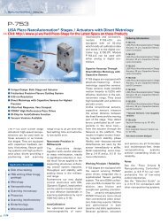
E-750.CP controller with<br />
P-752 NanoPositioning stage<br />
Application<br />
Examples<br />
� Head / media test<br />
� Track profiling<br />
� Scanning-probe microscopy<br />
� Micro-ablation and active optics.<br />
Ordering<br />
Information<br />
E-750.CP<br />
Digital NanoAutomation ® Controller<br />
E-751.PCI<br />
PCI Card with FiberLink Interface for<br />
three E-750<br />
E-751.<strong>PI</strong>O<br />
Parallel-Port-to-Fiber Converter<br />
Options<br />
E-751.F05<br />
5 m FiberLink Cable<br />
Custom Designs<br />
for Volume Buyers<br />
Notes<br />
Important Calibration Information:<br />
Please read details on page 6-41.<br />
6-12 6-12<br />
E-750.CP<br />
High-Speed Digital<br />
NanoAutomation ® Controller<br />
� Ultra-Fast Servo Loop:<br />
90 µsec<br />
� Optical FiberLink Interface<br />
(Optional): 1 Mbit/s<br />
� DSP-Based Real-Time<br />
Operating System<br />
� Additional High-Speed<br />
Analog Input<br />
� Optional InputShaping<br />
� AutoCalibration Function<br />
for NanoPositioning<br />
Systems with ID Chip<br />
� All Servo-Parameters<br />
Stored in Flash ROM<br />
The new E-750.CP digital PZT<br />
controller offers unmatched<br />
responsiveness and precision<br />
for the most demanding OEM<br />
applications. Driving the ultrafast<br />
P-752 and P-753 series<br />
NanoStages, the E-750 provides<br />
sub-millisecond settling<br />
and sub-angstrom (0.1 nm)<br />
resolution.<br />
http://www.pi.ws<br />
info@pi.ws<br />
Optional InputShaping<br />
The E-750 complements ultralow-noise<br />
PZT power amplifier,<br />
capacitive position sensing circuitry<br />
and sophisticated digital<br />
signal processing with fast<br />
servo-control algorithms. It is<br />
also the first system on the<br />
market offering <strong>PI</strong>’s exclusive<br />
Mach Throughput Coprocessor<br />
technology (InputShaping),<br />
which achieves the<br />
fastest possible overall system<br />
throughput by eliminating the<br />
effect of mechanical resonances<br />
(optional).{bk xtx6044}<br />
FiberLink Interface<br />
In addition, the E-750 is<br />
equipped with an ultra-fast<br />
(1 Mbit/sec) FiberLink Interface<br />
(distance up to 50 m) featuring<br />
complete electrical isolation<br />
to eliminate coupled EMI<br />
as a source of low-level position<br />
modulation. A high-bandwidth<br />
analog input (-10 to 10 V)<br />
is also standard.<br />
AutoCalibration<br />
OEM customers will appreciate<br />
the AutoCalibration function,<br />
allowing random combination<br />
(and easy interchange)<br />
of controllers and NanoPositioning<br />
systems with factory<br />
default configuration. Calibration<br />
data, linearization data and<br />
optimized servo-control parameters<br />
are stored in each<br />
NanoPositioning system and<br />
read by the controller upon<br />
power-up.<br />
Digital Linearization<br />
A digital linearization algorithm<br />
and the exclusive use of precision<br />
components in the controller<br />
guarantee excellent linearity<br />
and position accuracy.<br />
The controller is equipped with<br />
a wide-range power supply for<br />
use throughout the world.<br />
E-750.<strong>PI</strong>O parallel-port-to-fiber converter allows operation of the E-750 from a<br />
24-bit, high-speed parallel-port interface
E-751.PCI, PCI card with FiberLink<br />
interface for operation of up to 3 E-750 controllers<br />
E-750 software tool allows step-and-settle analysis and optimization of connected<br />
NanoPositioning system.<br />
Technical Data<br />
Models E-750.CP<br />
Function Digital NanoAutomation ® Controller<br />
Channels 1<br />
Processor 32-bit floating point DSP, 50 MHz<br />
Sampling rates 30 µs (Sensor), 90 µs (Servo Loop)<br />
Effective resolution DAC 20 bits<br />
Sensor types Capacitive, two-plate sensors<br />
RS-232 interface 115 kBit/s, BiSync protocol, ISO 1745-1975 (E)<br />
Fiber-Link interface (optional) 1 MBit/s<br />
Max. output power 10 W (see page 6-40)<br />
Current limitation Short-circuit proof<br />
Output voltage range -20 to +120 V<br />
PZT and sensor connector Combo sub-D; size DB, layout 7W2, 137W2SC30N40x (CONEC)<br />
Dimensions 125 x 50 x 262 mm<br />
Weight 2 kg<br />
Operating voltage range 90-264 VAC, 50-60 Hz, 30 VA<br />
PZT Actuators<br />
PZT Flexure NanoPositioners<br />
PZT Active Optics / Steering Mirrors<br />
Tutorial: Piezoelectrics...<br />
Capacitive Position Sensors<br />
PZT Control Electronics<br />
MicroPositioners / Hexapod Systems<br />
Photonics Alignment & Packaging Systems<br />
Motor Controllers<br />
Index<br />
http://www.pi.ws<br />
info@pi.ws<br />
6-13
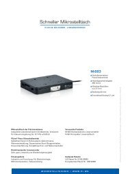
E-760<br />
E-760 controller card with P-611.3SF<br />
NanoCube ® XYZ NanoPositioning<br />
system<br />
Ordering<br />
Information<br />
E-760.3SV<br />
NanoCube ® Controller Card with<br />
Automatic Alignment Functions,<br />
Vis. Detector<br />
E-760.3Si<br />
NanoCube ® Controller Card with<br />
Automatic Alignment Functions,<br />
IR Detector<br />
Custom Designs<br />
for Volume Buyers<br />
NanoCube ® Controller Card with<br />
Automatic Alignment Functions<br />
� Specially Designed for<br />
P-611 NanoCube ® and<br />
F-206 HexAlign 6D<br />
Alignment System<br />
� Built-in Optical Metrology<br />
for Automatic Alignment<br />
� 3 x 9 W Peak Power<br />
� Position Servo-Control<br />
The E-760 is a PZT amplifier<br />
and position servo-controller<br />
card that was especially<br />
designed for the P-611<br />
NanoCube ® XYZ NanoAlignment<br />
system (see pages 2-36<br />
and 8-16). In addition to three<br />
low-noise amplifiers and position<br />
servo-controller circuits, it<br />
is equipped with optical<br />
metrology and I/O for auto-<br />
Technical Data<br />
PZT Actuators<br />
PZT Flexure NanoPositioners<br />
PZT Active Optics / Steering Mirrors<br />
Tutorial: Piezoelectrics...<br />
Capacitive Position Sensors<br />
PZT Control Electronics<br />
MicroPositioners / Hexapod Systems<br />
Photonics Alignment & Packaging Systems<br />
Motor Controllers<br />
Index<br />
http://www.pi.ws<br />
info@pi.ws<br />
matic alignment of photonics<br />
components. All functions are<br />
accessible via the PC-bus interface.<br />
In addition, there is an<br />
analog input for position control<br />
and an FC connector for<br />
the optical metrology.<br />
Models E-760.3SV, E-760.3Si<br />
Function Power amplifier & sensor / position servo-control of<br />
P-611 NanoCube ® systems with additional optical<br />
metrology and I/O for automated alignment<br />
Channels<br />
<strong>Amplifier</strong><br />
3<br />
Maximum output power 9 W per channel (see page 6-40)<br />
Average output power 1 W per channel<br />
Peak output current < 5 ms 90 mA<br />
Average output current > 5 ms 30 mA<br />
Current limitation Short-circuit proof<br />
Voltage gain 10 ±0.1<br />
Polarity Positive<br />
Control input voltage -2 to +12 V<br />
Output voltage -20 to 120 V<br />
PZT voltage output socket 25 pin sub-D on rear<br />
Analog in/out socket 8 pin network connector on rear<br />
Dimensions<br />
Position Servo-Control<br />
PC Card (ISA)<br />
Sensor Type Strain Gauge<br />
Servo Characteristics P-I (analog) + notch filter<br />
Sensor socket 25 pin sub-D on rear (same as PZT voltage)<br />
Optical Metrology IR detector (E-760.3Si), Vis detector (E-760.3SV),<br />
input via FC connector<br />
6-14<br />
E760/E/04/10/18.0
E-664.S3<br />
Ordering<br />
Information<br />
E-664.S3<br />
NanoCube Controller, Benchtop<br />
Custom Designs<br />
for Volume Buyers<br />
NanoCube Controller<br />
E-664 controller for P-611 NanoCube<br />
XYZ NanoPositioning system<br />
� 3 x 14 W Peak Power<br />
� Position Servo-Control<br />
� For P-611 NanoCube<br />
NanoPositioning Systems<br />
The E-664 is a bench-top<br />
amplifier & position servo-controller<br />
that was especially<br />
designed for the P-611 Nano-<br />
Cube XYZ NanoAlignment<br />
system (see pages 2-36 and<br />
8-16). Each of the three<br />
integrated low-noise amplifiers<br />
can output and sink a peak<br />
current of 140 mA and an<br />
average current of 60 mA. The<br />
position servo-controllers work<br />
with strain gauge sensors. The<br />
E-664 can be operated in the<br />
following four ways:<br />
I. Open-Loop Manual Operation:<br />
Output voltage can<br />
be set by a 10-turn, DC-offset<br />
potentiometer in the<br />
range of 0 to 100 V.<br />
II. Open-Loop External Operation<br />
(amplifier mode):<br />
Output voltage is controlled<br />
by an analog signal applied<br />
to the BNC input ranging<br />
from -2 to +12 V. Multi-<br />
plying by the gain factor of<br />
10, an output voltage range<br />
of -20 to +120 V results.<br />
The DC-offset potentiometer<br />
adds a DC bias to the<br />
input, allowing continuous<br />
shifting of the input voltage<br />
range between -2 V to<br />
+12 V and -12 V to +2 V<br />
(see page 6-40).<br />
III. Closed-Loop Manual<br />
Operation (position control<br />
mode): Displacement<br />
of the PZTs can be set by a<br />
10-turn, DC-offset potentiometer<br />
in the range of zero<br />
to nominal displacement.<br />
IV. Closed-Loop External<br />
Operation: Displacement<br />
of the PZT is controlled by<br />
an analog signal in the<br />
range of 0 to +10 V applied<br />
to the BNC input.<br />
Technical Data<br />
The controller is calibrated<br />
in such a way that 10 V corresponds<br />
to maximum<br />
nominal displacement and<br />
0 V corresponds to 0 displacement.<br />
The DC-offset<br />
potentiometer can be used<br />
to add an offset voltage of<br />
0 to 10 V to the input signal.<br />
On-Target and Overflow<br />
status for each channel<br />
are displayed by 6 LEDs<br />
and can be accessed<br />
through a 14-pin, rearmount<br />
I/O connector that<br />
also provides analog control<br />
input and sensor monitor<br />
output lines.<br />
Models E-664.S3<br />
Function Power amplifier & sensor/position servo-control of<br />
P-611 NanoCube NanoPositioning systems<br />
Channels<br />
<strong>Amplifier</strong><br />
3<br />
Maximum output power 14 W (see page 6-40)<br />
Average output power 6 W<br />
Peak output current < 5 ms 140 mA<br />
Average output current > 5 ms 60 mA<br />
Current limitation Short-circuit proof<br />
Voltage gain 10 ±0.1<br />
Polarity Positive<br />
Control input voltage -2 to +12 V<br />
Output voltage -20 to 120 V<br />
DC offset setting 0 to 100 V with 10-turn pot.<br />
Input impedance 100 k�<br />
Display 3 x 3 1 / 2 -digit, LED<br />
Control input sockets: BNC (rear)<br />
PZT voltage output socket 25 pin sub-D on rear<br />
Dimensions 235 x 103 x 288 mm<br />
Weight 3.0 kg<br />
Operating voltage 90-120 / 220-240 VAC, 50-60 Hz (linear P/S)<br />
Position Servo-Control<br />
Sensor type Strain Gauge<br />
PZT Actuators<br />
Servo characteristics P-I (analog) + notch filter<br />
PZT Flexure NanoPositioners<br />
PZT Active Optics / Steering Mirrors<br />
Tutorial: Piezoelectrics...<br />
Capacitive Position Sensors<br />
PZT Control Electronics<br />
MicroPositioners / Hexapod Systems<br />
Photonics Alignment & Packaging Systems<br />
Motor Controllers<br />
Index<br />
Sensor socket 25 pin sub-D on rear (same as PZT voltage)<br />
http://www.pi.ws<br />
info@pi.ws<br />
Sensor monitor output socket BNC<br />
Additional I/O 14 pin connector on rear for On-Target and<br />
Overflow status and control in and sensor monitor out<br />
6-15 6-15
E-665.SR<br />
Ordering<br />
Information<br />
E-665.SR<br />
<strong>LVPZT</strong> <strong>Amplifier</strong> & Position Controller,<br />
Strain Gauge Sensors, RS-232 Interface<br />
E-665.LR<br />
<strong>LVPZT</strong> <strong>Amplifier</strong> & Position Controller,<br />
LVDT Sensors, RS-232 Interface<br />
E-665.CR<br />
<strong>LVPZT</strong> <strong>Amplifier</strong> & Position Controller,<br />
Capacitive Sensors, RS-232 Interface<br />
Custom Designs for Volume Buyers<br />
6-16<br />
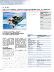
E-665<br />
<strong>LVPZT</strong> <strong>Amplifier</strong> & Position Servo-Controller<br />
with High-Speed RS-232 Interface<br />
� Integrated 20-Bit High-<br />
Speed RS-232 Interface<br />
� Network Capability with<br />
up to 12 Channels<br />
� 36 W Peak Power<br />
� Position Servo-Control<br />
� For Strain Gauge, LVDT<br />
and Capacitive Sensors<br />
The E-665 is a bench-top, lowvoltage<br />
PZT amplifier and position<br />
servo-controller with integrated<br />
high-speed RS-232<br />
computer interface and a 20bit<br />
D/A converter. The E-665<br />
supports all position sensors<br />
offered with <strong>PI</strong> piezo translators<br />
and NanoPositioning stages:<br />
strain gauge sensors, LVDT<br />
sensors and capacitive sensors.<br />
It is ideal for use with single-axis<br />
translators such as<br />
� P-841 stack actuators with<br />
strain gauge sensors<br />
� P-721 <strong>PI</strong>FOC ® microscope<br />
objective positioners with<br />
LVDT or capacitive sensors<br />
� P-620 <strong>PI</strong>Hera series singleaxis<br />
stages with travel up to<br />
500µmandcapacitive sensors<br />
� P-753 LISA/P-752 series<br />
NanoAutomation ® stages<br />
with capacitive sensors<br />
http://www.pi.ws<br />
info@pi.ws<br />
New and Fast<br />
Communications Interface<br />
The RS-232 interface handles<br />
communications with the outside<br />
world. It performs up to<br />
300 bidirectional read or write<br />
operations per second and<br />
incorporates precision 20-bit<br />
D/A and A/D converters for<br />
exceptional positional stability<br />
and resolution.<br />
Multi-Axis Network<br />
Up to 12 E-665s can be networked<br />
and controlled over a<br />
single RS-232 interface.<br />
<strong>PI</strong> General Command Set<br />
The E-665 is to a large extent<br />
freely programmable and its<br />
command structure conforms<br />
to the <strong>PI</strong> General Command<br />
Set. This command set is common<br />
to the E-516 Computer<br />
Control and Display <strong>Module</strong><br />
and an increasing number of <strong>PI</strong><br />
controllers, and is designed for<br />
multi-axis operation. It is <strong>PI</strong>’s<br />
goal to make all of its controllers<br />
“understand” these<br />
commands, either directly or<br />
via command libraries. This will<br />
greatly reduce the effort<br />
required to produce custom<br />
programs, especially in environments<br />
which include a<br />
number of different controllers.<br />
Included with the E-665 is<br />
user-interface software as well<br />
LabView and other driver<br />
sets.<br />
Screenshot of PZT-Control software for E-665. The commands listed in the editor are<br />
part of the <strong>PI</strong> General Command Set.
E-665, open-loop frequency with various PZT loads. Capacitance values are in µF,<br />
measured in actual PZT.<br />
Technical Data<br />
PZT Actuators<br />
PZT Flexure NanoPositioners<br />
PZT Active Optics / Steering Mirrors<br />
Tutorial: Piezoelectrics...<br />
Capacitive Position Sensors<br />
PZT Control Electronics<br />
MicroPositioners / Hexapod Systems<br />
Photonics Alignment & Packaging Systems<br />
Motor Controllers<br />
Index<br />
http://www.pi.ws<br />
info@pi.ws<br />
Models E-665.SR E-665.LR E-665.CR<br />
Function Power amplifier & sensor/ Power amplifier & sensor/ Power amplifier & sensor/<br />
position servo-control of <strong>LVPZT</strong>s position servo-control of <strong>LVPZT</strong>s position servo-control of <strong>LVPZT</strong>s<br />
Channels<br />
<strong>Amplifier</strong><br />
1 1 1<br />
Maximum output power 36 W 36 W 36 W<br />
Average output power 12 W 12 W 12 W<br />
Peak output current < 5 ms 360 mA 360 mA 360 mA<br />
Average output current > 5 ms 120 mA 120 mA 120 mA<br />
Current limitation short-circuit proof short-circuit proof short-circuit proof<br />
Voltage gain 10 ± 0.1 10 ± 0.1 10 ± 0.1<br />
Polarity Positive Positive Positive<br />
Control input voltage -2 to +12 V -2 to +12 V -2 to +12 V<br />
Output voltage -20 to 120 V -20 to 120 V -20 to 120 V<br />
DC offset setting 0 to 100 V with 10-turn pot. 0 to 100 V with 10-turn pot. 0 to 100 V with 10-turn pot.<br />
Input impedance 100 k� 100 k� 100 k�<br />
Display 2 x 4 1/2-digit, LED 2 x 4 1/2-digit, LED 2 x 4 1/2-digit, LED<br />
Control input socket: BNC BNC BNC<br />
PZT voltage output socket LEMO ERA.00.250.CTL LEMO ERA.00.250.CTL Combo sub-D; size DB<br />
Dimensions 235 x 103 x 288 mm 235 x 103 x 288 mm 235 x 103 x 288 mm<br />
Weight 2.5 kg 2.5 kg 2.5 kg<br />
Operating voltage 90 –120 / 220–240 VAC, 90–120 / 220–240 VAC, 90 –120 / 220–240 VAC,<br />
RS-232 Interface<br />
50 –60 Hz (linear P/S) 50–60 Hz (linear P/S) 50–60 Hz (linear P/S)<br />
D/A Converter 20-bit resolution 20-bit resolution 20-bit resolution<br />
Baudrate 9.6 kBaud –115.2 kBaud 9.6 kBaud –115.2 kBaud 9.6 kBaud – 115.2 kBaud<br />
(default 115.2 kBaud) (default 115.2 kBaud) (default 115.2 kBaud)<br />
Wave Table 64 data points, 100 Hz, 64 data points, 100 Hz, 64 data points, 100 Hz,<br />
Position Servo-Control<br />
externally triggered externally triggered externally triggered<br />
Sensor Type SGS LVDT capacitive<br />
Servo Characteristics P-I (analog) + notch filter P-I (analog) + notch filter P-I (analog) + notch filter<br />
Sensor socket LEMO ERA.0S.304.CLL LEMO ERA.0S.304.CLL Combo sub-D; size DB<br />
Sensor monitor output socket BNC BNC BNC<br />
6-17
E-610<br />
Notes<br />
Important Calibration Information:<br />
Please read details on page 6-41.<br />
6-18 6-18 6-18 6-18<br />
E-610<br />
<strong>LVPZT</strong> <strong>Amplifier</strong> & Position<br />
Servo-Controller <strong>Module</strong>s, OEM Version<br />
� Open-Loop and Closed-<br />
Loop Versions<br />
� Optional RS-232 Interface<br />
� For Capacitive, Strain<br />
Gauge and LVDT Sensors<br />
� 14 W Peak Power<br />
� Runs on Single Stabilized<br />
Voltage (12 to 30 VDC)<br />
The E-610 is an OEM, standalone,<br />
amplifier & position<br />
servo-control board for lowvoltage<br />
PZTs. Four versions are<br />
available: E-610.00 (open-loop,<br />
amplifier only) and the closedloop<br />
versions E-610.S0,<br />
E-610.L0 and E-610.C0 (with<br />
additional circuitry for position<br />
sensing and servo-control).<br />
Version E-610.S0 controls<br />
strain-gauge-sensor-equipped<br />
PZTs, version E-610.L0 controls<br />
LVDT-sensor-equipped<br />
PZTs and version E-610.C0<br />
controls capacitive-sensorequipped<br />
PZTs. The open-loop<br />
version (E-610.00) can be operated<br />
in two ways, the closedloop<br />
versions in four ways:<br />
http://www.pi.ws<br />
info@pi.ws<br />
I. Open-Loop External Operation<br />
(amplifier mode):<br />
Output voltage is controlled<br />
by an analog signal ranging<br />
from -2 to +12 V. Multiplying<br />
by the gain factor of<br />
10, an output voltage range<br />
of -20 to +120 V results. If<br />
an external offset potentiometer<br />
(not included) is<br />
connected, it allows for continuous<br />
shifting of the input<br />
range between -2 V to +12 V<br />
and -12 V to +2 V (see page<br />
6-40).<br />
II. Open-Loop Manual Operation<br />
(power supply<br />
mode): With 0 V input signal,<br />
output voltage can be<br />
set by an external, DC-offset<br />
potentiometer (not<br />
included) in the range of<br />
0 to 100 V.<br />
III. Closed-Loop (positioncontrol<br />
mode) External<br />
Operation: Displacement<br />
of the PZT is controlled by<br />
an analog signal in the range<br />
of 0 to +10 V. The controller<br />
is calibrated in such a way<br />
that 10 V corresponds to<br />
maximum nominal displacement<br />
and 0 V corresponds<br />
to zero displacement. If an<br />
external offset potentiometer<br />
(not included) is connected,<br />
it can be used to<br />
add an offset voltage of 0 to<br />
10 V to the input signal.<br />
IV. Closed-Loop Manual Operation:<br />
With 0 V input signal,<br />
displacement of the<br />
PZTs can be set by a DCoffset<br />
potentiometer (not<br />
included) in the range of zero<br />
to nominal displacement.<br />
Only one unipolar stabilized<br />
voltage in the range of 12 to<br />
30 VDC is required to operate<br />
the E-610. An integrated<br />
DC/DC converter generates<br />
the PZT operating voltage and<br />
all other voltages used internally.<br />
All inputs and outputs<br />
are via the male 32-pin rear<br />
connector. A matching female<br />
32-pin connector, a LEMO<br />
ERA.00.250.CTL PZT operating<br />
voltage connector, and a<br />
LEMO ERA.0S.304.CLL sensor<br />
connector are included to<br />
interface with standard <strong>PI</strong><br />
<strong>LVPZT</strong>s.<br />
Computer Controlled Mode:<br />
See E-621 modules, page 6-47.
E-610, open-loop frequency response with various PZT loads. Values shown are capacitance in µF, measured in actual PZT.<br />
Ordering<br />
Information<br />
E-610.00<br />
<strong>LVPZT</strong> <strong>Amplifier</strong> <strong>Module</strong>, OEM<br />
E-610.C0<br />
<strong>LVPZT</strong> <strong>Amplifier</strong>/ Controller <strong>Module</strong>,<br />
Capacitive Sensor, OEM<br />
E-610.L0<br />
<strong>LVPZT</strong> <strong>Amplifier</strong>/Controller <strong>Module</strong>,<br />
LVDT Sensor, OEM<br />
E-610.S0<br />
<strong>LVPZT</strong> <strong>Amplifier</strong>/Controller <strong>Module</strong>,<br />
Strain Gauge Sensor, OEM<br />
Computer Controlled Models:<br />
See E-621, page 6-47<br />
Custom Designs<br />
for Volume Buyers<br />
Technical Data<br />
Models E-610.00, E-610.CO, E-610.LO, E-610.SO<br />
Function power amplifier & sensor/position servo-control of PZTs<br />
Channels 1<br />
<strong>Amplifier</strong><br />
Maximum output power 14 W (see page 6-40)<br />
Average output power 6 W<br />
Peak output current < 5 ms 140 mA<br />
Average output current > 5 ms 60 mA<br />
Current limitation short-circuit proof<br />
Voltage gain 10 ±0.1<br />
Polarity positive<br />
Control input voltage -2 to +12 V<br />
Output voltage -20 to 120 V<br />
DC-offset setting 0 to 100 V at output, with external potentiometer<br />
(not included)<br />
Input impedance 100 k�<br />
Input/output connector 32-pin (male) on rear panel (DIN 41612/D)<br />
Dimensions one 7T slot wide, 3H high<br />
Weight 0.35 kg (E-610.00: 0.3 kg)<br />
Operating voltage 12 to 30 VDC, stabilized<br />
Operating current 2 A<br />
Position Servo-Control (except E-610.00)<br />
Sensor Types strain gauge (E-610.S0); LVDT (E-610.L0),<br />
capacitive (E-610.C0)<br />
Servo Characteristics P-I (analog) + notch filter<br />
Sensor Socket LEMO ERA.0S.304.CLL (included)<br />
PZT Actuators<br />
PZT Flexure NanoPositioners<br />
PZT Active Optics / Steering Mirrors<br />
Tutorial: Piezoelectrics...<br />
Capacitive Position Sensors<br />
PZT Control Electronics<br />
MicroPositioners / Hexapod Systems<br />
Photonics Alignment & Packaging Systems<br />
Motor Controllers<br />
Index<br />
http://www.pi.ws<br />
info@pi.ws<br />
6-19
Ordering<br />
Information<br />
E-500.00<br />
PZT-<strong>Amplifier</strong> & Position-Servo-<br />
Controller, Up to 3 Channels, Basic<br />
Chassis, 19”<br />
E-501.00<br />
PZT-<strong>Amplifier</strong> & Position-Servo-<br />
Controller, Up to 3 Channels, Basic<br />
Chassis, 9.5”<br />
Custom Designs<br />
for Volume Buyers<br />
6-20 6-20 6-20 6-20<br />
E-500<br />
E-501<br />
Configuration example: E-501 chassis with optional E-503 <strong>LVPZT</strong> amplifier,<br />
E-509.C3A PZT servo-controller for capacitive sensors and E-516.i3 20-bit DAC<br />
Interface/Display.<br />
Modular PZT Control Systems<br />
(HVPZT & <strong>LVPZT</strong>)<br />
Technical Data<br />
http://www.pi.ws<br />
info@pi.ws<br />
� For High- and Low-<br />
Voltage PZTs<br />
� 19- and 9.5-Inch Chassis<br />
� Optional Position Servo-<br />
Control <strong>Module</strong>s<br />
� Optional Display and RS-<br />
232 & IEEE 488 Interface<br />
<strong>Module</strong><br />
The E-500 is a modular, 19”<br />
rackmount chassis for PZT<br />
amplifiers and position servocontrollers.<br />
An integrated<br />
multi-function power supply<br />
(E-530.00) provides operating<br />
voltages for all available modules.<br />
E-500 chassis are assembled<br />
to order and tested with<br />
all ordered modules installed.<br />
A maximum of 3 amplifier/controller<br />
channels can be<br />
installed in one E-500 chassis.<br />
The E-501.00 is the 9.5” version<br />
of the E-500 chassis.<br />
Note: only one amplifier module<br />
(1 or 3 channels) and only<br />
one sensor/servo-controller<br />
module (1 or 3 channels) can<br />
be installed in the E-501. A<br />
modified E-500 chassis for up<br />
to 6 channels is available on<br />
request.<br />
Configuration example: E-500 chassis with three optional E-507 HVPZT <strong>Amplifier</strong>s,<br />
E-509.L3 PZT Servo-Controller for LVDT sensors and E-516.i3 20-bit DAC face/Display.<br />
Models E-500.00 E-501.00<br />
Function 19” chassis for PZT electronics: amplifier modules, 9.5” chassis for PZT electronics: amplifier modules,<br />
sensor modules, position servo-control modules, sensor modules, position servo-control modules,<br />
display/interface modules display/interface modules<br />
Channels 1, 2, 3 1, 3<br />
Dimensions 450 x 158 x 288 mm (see p. 6-7) 235 x 158 x 288 mm (see p. 6-7)<br />
Integrated power supply E-530.00 E-531.00<br />
Operating voltage 90-264 VAC, 50-60 Hz, E-530.00 primary switching P/S; 90-120 / 220-264 VAC, 50-60 Hz, E-531.00 linear P/S
E-500<br />
E-501<br />
Ordering<br />
Information<br />
For Ordering Examples and<br />
<strong>Module</strong> Survey see page 6-22.<br />
System Configuration<br />
Configuration Example:<br />
E-500 chassis with optional E-503 <strong>LVPZT</strong> amplifier,<br />
3 channels, 3 x E-509 PZT servo-controller (E-509.S1:<br />
strain gauges, E-509.L1: LVDTs, E-509.C1A: capacitive sensors)<br />
and E-516.i3 20-bit DAC interface/display.<br />
E-500, E-501 System Configuration<br />
Installable <strong>Amplifier</strong> <strong>Module</strong>s<br />
E-503.00 (LV, 3 ch)<br />
E-505.00 (LV, 1 ch)<br />
E-507.00 (HV, 1 ch)<br />
E-500, 19” Chassis Models<br />
E-501, 9.5” Chassis<br />
Contr. <strong>Amplifier</strong> Contr. <strong>Amplifier</strong> Contr. <strong>Amplifier</strong> Display/Interface Slot<br />
Slot 3 Slot 3 Slot 2 Slot 2 Slot 1 Slot 1<br />
Installable Sensor & Position Servo-Control <strong>Module</strong>s<br />
E-509.C1A (Cap., 1 ch)<br />
E-509.L1 (LVDT, 1 ch)<br />
E-509.S1 (SGS, 1 ch)<br />
E-509.C2A (Cap., 2 ch)<br />
E-509.C3A (Cap., 3 ch)<br />
E-509.L3 (LVDT, 3 ch)<br />
E-509.S3 (SGS, 3 ch)<br />
Installable Display/Interface <strong>Module</strong>s<br />
E-515.01 (1 ch)<br />
E-515.03 (3 ch)<br />
E-516.i3 (3 ch)<br />
Minimal Configuration, PZT <strong>Amplifier</strong> Function only<br />
Extended Configuration, PZT <strong>Amplifier</strong> with additional Position Servo-Controller<br />
Extended Configuration, PZT <strong>Amplifier</strong> with additional Display (and Interface, no Servo-Controller)<br />
Extended Configuration, PZT <strong>Amplifier</strong> with additional Position Servo-Controller and Display (and Interface)<br />
Can be installed in E-500 Can be installed in E-501 or E-500<br />
HV: High Voltage LV: Low Voltage<br />
6-21 6-21 6-21 6-21
6-22 6-22 6-22 6-22 6-22<br />
E-500<br />
E-501<br />
The following modules can<br />
be installed in E-500 / E-501<br />
chassis:<br />
<strong>Module</strong> Survey & Ordering Examples<br />
� <strong>Amplifier</strong> modules<br />
(see page 6-33 ff.)<br />
E-503.00<br />
<strong>LVPZT</strong> <strong>Amplifier</strong> <strong>Module</strong>,<br />
3 Channels, -20 to +120 V,<br />
3 x 6 W<br />
E-505.00<br />
<strong>LVPZT</strong> <strong>Amplifier</strong> <strong>Module</strong>,<br />
-20 to +120 V, 30 W,<br />
1 Channel<br />
E-507.00<br />
HVPZT <strong>Amplifier</strong> <strong>Module</strong>,<br />
-3 to -1100 V, 13 W,<br />
1 Channel<br />
http://www.pi.ws<br />
info@pi.ws<br />
� Display & DAC-Interface<br />
<strong>Module</strong>s (see page 6-37)<br />
E-516.i3<br />
20-bit DAC Interface/<br />
Display <strong>Module</strong>, IEEE<br />
488/RS-232, 3 Channels<br />
E-515.01<br />
Display <strong>Module</strong> for PZT<br />
Voltage/Displacement<br />
E-515.03<br />
Display <strong>Module</strong> for PZT<br />
Voltage/Displacement,<br />
3 Channels<br />
� Sensor & Controller<br />
<strong>Module</strong>s (see page 6-36)<br />
E-509.C1A<br />
PZT Sensor/Controller<br />
<strong>Module</strong>,<br />
Capacitive Sensor<br />
E-509.L1<br />
PZT Sensor/Controller<br />
<strong>Module</strong>, LVDT Sensor<br />
E-509.S1<br />
PZT Sensor/Controller<br />
<strong>Module</strong>, Strain Gauge<br />
Sensor<br />
E-509.C2A<br />
PZT Sensor/Controller<br />
<strong>Module</strong>, Capacitive Sensor,<br />
2 Channels<br />
E-509.C3A<br />
PZT Sensor/Controller<br />
<strong>Module</strong>, Capacitive Sensor,<br />
3 Channels<br />
E-509.L3<br />
PZT Sensor/Controller<br />
<strong>Module</strong>, LVDT Sensor,<br />
3 Channels<br />
E-509.S3<br />
PZT Sensor/Controller<br />
<strong>Module</strong>, Strain Gauge<br />
Sensor, 3 Channels
Configuration Examples<br />
� <strong>LVPZT</strong> <strong>Amplifier</strong>,<br />
3 Channels, (6 W)<br />
without Display:<br />
1 x E-500.00 (E-501.00)<br />
Modular PZT Control<br />
System, 19” Basic<br />
Chassis<br />
1 x E-503.00<br />
<strong>LVPZT</strong> <strong>Amplifier</strong> <strong>Module</strong>,<br />
3 Channels, -20 to +120 V,<br />
3 x 6 W<br />
� HVPZT <strong>Amplifier</strong>,<br />
3 Channels, with DAC<br />
Interface & Display:<br />
1 x E-500.00<br />
Modular PZT Control<br />
System, 19” Basic<br />
Chassis<br />
3 x E-507.00{bk<br />
xtx6149}<br />
HVPZT <strong>Amplifier</strong> <strong>Module</strong>,<br />
-3 to -1100 V, 13 W<br />
1 x E-516.i3<br />
DAC Interface/Display<br />
<strong>Module</strong>, IEEE 488/RS-232,<br />
3 Channels<br />
� HVPZT <strong>Amplifier</strong> &<br />
Position Servo-Controller<br />
(LVDT Sensors),<br />
3 Channels, with Display<br />
& DAC Interface:<br />
1 x E-500.00<br />
Modular PZT Control<br />
System, 19” Basic<br />
Chassis<br />
3 x E-507.00<br />
HVPZT <strong>Amplifier</strong> <strong>Module</strong>,<br />
-3 to -1100 V, 13 W<br />
1 x E-509.L3<br />
PZT Sensor/Controller<br />
<strong>Module</strong>, LVDT Sensor,<br />
3 Channels<br />
1 x E-516.i3<br />
DAC Interface/Display<br />
<strong>Module</strong>, IEEE 488/RS-232,<br />
3 Channels<br />
� Closed-loop operation<br />
of P-733.2CL XY PZT<br />
stage (capacitive<br />
sensors) shortest<br />
possible step response,<br />
computer control:<br />
1 x E-500.00<br />
Modular PZT Control<br />
System, 19” Basic<br />
Chassis<br />
2 x E-505.00<br />
<strong>LVPZT</strong> <strong>Amplifier</strong> <strong>Module</strong>,<br />
-20 to +120 V, 30 W<br />
1 x E-509.C2A<br />
PZT Sensor/Controller<br />
<strong>Module</strong>, Capacitive<br />
Sensor, 2 Channels<br />
1 x E-516.i3<br />
20-bit DAC Interface/<br />
Display <strong>Module</strong>, IEEE<br />
488/RS-232, 3 Channels<br />
� Closed-loop operation<br />
of the P-733.2CL XY PZT<br />
stage (capacitive<br />
sensors) and P-721.20<br />
<strong>PI</strong>FOC objective<br />
positioner (capacitive<br />
sensor), static and slow<br />
operation, computer<br />
control, 9.5” chassis:<br />
1 x E-501.00<br />
Modular PZT Control<br />
System, 9.5” Basic<br />
Chassis<br />
1 x E-503.00<br />
<strong>LVPZT</strong> <strong>Amplifier</strong> <strong>Module</strong>,<br />
3 Channels, -20 to +120 V,<br />
3 x 6 W<br />
1 x E-509.C3A<br />
PZT Sensor/Controller<br />
<strong>Module</strong>, Capacitive<br />
Sensor, 3 Channels<br />
1 x E-516.i3<br />
20-bit DAC Interface/<br />
Display <strong>Module</strong>, IEEE<br />
488/RS-232, 3 Channels<br />
� Closed-loop operation of<br />
S-340 tip/tilt platform<br />
(LVDT sensors), shortest<br />
possible step response,<br />
external analog control:<br />
1 x E-500.00<br />
Modular PZT Control<br />
System, 19” Basic<br />
Chassis<br />
3 x E-505.00<br />
<strong>LVPZT</strong> <strong>Amplifier</strong> <strong>Module</strong>,<br />
-20 to +120 V, 30 W<br />
1 x E-509.L3<br />
PZT Sensor/Controller<br />
<strong>Module</strong>, LVDT Sensor,<br />
3 Channels<br />
� Closed-loop operation of<br />
P-733.2CL XY stage<br />
(capacitive sensors) and<br />
P-721.10 <strong>PI</strong>FOC objective<br />
positioner (LVDT<br />
sensor), shortest<br />
possible step response,<br />
computer control:<br />
1 x E-500.00<br />
Modular PZT Control<br />
System, 19” Basic<br />
Chassis<br />
3 x E-505.00<br />
<strong>LVPZT</strong> <strong>Amplifier</strong> <strong>Module</strong>,<br />
-20 to +120 V, 30 W<br />
2 x E-509.C1A<br />
PZT Sensor/Controller<br />
<strong>Module</strong>, Capacitive Sensor<br />
1 x E-509.L1<br />
PZT Sensor/Controller<br />
<strong>Module</strong>, LVDT Sensor<br />
1 x E-516.i3<br />
20-bit DAC Interface/<br />
Display <strong>Module</strong>, IEEE<br />
488/RS-232, 3 Channels<br />
� Closed-loop operation<br />
of 3 P-841.10 <strong>LVPZT</strong><br />
translators (strain gauge<br />
sensors) static and slow<br />
operation, external<br />
analog control, future<br />
upgrade for faster<br />
operation possible:<br />
1 x E-500.00<br />
Modular PZT Control<br />
System, 19” Basic<br />
Chassis (can<br />
accommodate<br />
3 x E-505, 30 W<br />
amplifiers)<br />
1 x E-503.00<br />
<strong>LVPZT</strong> <strong>Amplifier</strong> <strong>Module</strong>,<br />
3 Channels,<br />
-20 to +120 V, 3 x 6 W<br />
1 x E-509.S3<br />
PZT Sensor/Controller<br />
<strong>Module</strong>, Strain Gauge<br />
Sensor, 3 Channels<br />
Optional:<br />
1 x E-515.03<br />
Display <strong>Module</strong> for PZT<br />
Voltage / Displacement,<br />
3 Channels<br />
6-23 6-23
Ordering<br />
Information<br />
E-470.00<br />
HVPZT <strong>Amplifier</strong>, 500 W,<br />
-3 to -1100 V, Bench-Top<br />
E-471.00<br />
HVPZT <strong>Amplifier</strong>, Controller &<br />
Interface/Display Upgrade Possible,<br />
500 W, -3 to -1100 V, 19”<br />
E-472.00<br />
HVPZT <strong>Amplifier</strong>, 2 Channels, 500 W,<br />
-3 to -1100 V, Bench-Top, 19”<br />
E-420.00<br />
HVPZT <strong>Amplifier</strong> <strong>Module</strong>, 500 W,<br />
-3 to -1100 V<br />
Upgrades<br />
E-509.C1A<br />
PZT Sensor-Controller module<br />
(capacitive sensor)<br />
E-509.L1<br />
PZT Sensor/Controller module<br />
(LVDT sensor)<br />
E-509.S1<br />
PZT Sensor/Controller module<br />
(strain gauge sensor)<br />
Computer Interface and Display<br />
<strong>Module</strong> (see page 6-37)<br />
E-516.i3<br />
20-bit DAC Interface/Display module,<br />
IEEE 488 / RS-232<br />
Voltage & Position Display<br />
<strong>Module</strong> (see page 6-38)<br />
E-515.01<br />
Display <strong>Module</strong> for PZT Voltage and<br />
Displacement<br />
Sensor & Servo-Controller<br />
<strong>Module</strong>s for Closed-Loop PZT<br />
Operation (see page 6-36)<br />
Custom Designs<br />
for Volume Buyers<br />
Notes<br />
Important Calibration Information:<br />
Please read details on page 6-41.<br />
6-24<br />
E-470<br />
E-471<br />
E-472<br />
E-420<br />
High-Power, Modular HVPZT<br />
<strong>Amplifier</strong>/Controllers<br />
E-471.00 Configuration example: E-471.00 HVPZT amplifier, with optional E-509.S1<br />
PZT servo-controller (strain gauges) and E-516.i3 20-bit DAC interface/display.<br />
� 500 W Peak Power<br />
� Output Voltage -3 to<br />
-1100 V & Bipolar<br />
� 1 and 2 Channel Versions<br />
� Optional Position Servo-<br />
Control <strong>Module</strong>s<br />
� Optional RS-232 & IEEE<br />
488 Interface <strong>Module</strong> &<br />
Display<br />
The E-470 series high-power<br />
amplifier/controllers are specifically<br />
designed to drive highcapacitance<br />
PZT actuators.<br />
They are based on the E-420<br />
amplifier module, which can<br />
output and sink a peak current<br />
of 500 mA and an average current<br />
of 100 mA in a voltage<br />
range of -3 to -1100 V (positive<br />
or bipolar range, jumper selectable).<br />
OEM, 19” rackmount,<br />
bench-top, and two-channel<br />
versions are available, some<br />
with servo-control module and<br />
display (see Ordering Information<br />
for standard combinations).<br />
http://www.pi.ws<br />
info@pi.ws<br />
Standard versions can be operated<br />
in two ways:<br />
I. Manual operation: The<br />
output voltage can be set by<br />
a 10-turn, DC-offset potentiometer<br />
in the range of<br />
-3 to -1000 Volts<br />
II. External operation: Output<br />
voltage is controlled by an<br />
analog signal applied to the<br />
BNC input, ranging from 0<br />
to 11 Volts. Multiplying by<br />
the gain factor of -100, an<br />
output voltage range of -3 to<br />
-1100 Volts results. The DCoffset<br />
potentiometer adds a<br />
DC bias to the input, allowing<br />
continuous shifting of<br />
the input range between<br />
0 V to +10 V and -10 V to<br />
0 V (see page 6.31).<br />
See graph for frequency<br />
response with selected HVPZTs.<br />
Upgrades<br />
The E-471.00 version allows<br />
installation several upgrade<br />
options for enhanced versatility<br />
(see Ordering Information).<br />
Two additional modes are possible<br />
with versions having the<br />
E-509 Sensor & Servo-Controller<br />
<strong>Module</strong> upgrade:<br />
I. Manual Closed-Loop Operation<br />
Displacement of the PZTs<br />
can be set by a 10-turn DCoffset<br />
potentiometer in the<br />
range of zero to nominal displacement.<br />
II. External Closed-Loop Operation<br />
Displacement of the PZT is<br />
controlled by an analog signal<br />
in the range of 0 to<br />
+10 V, applied to the BNC<br />
input. The controller is calibrated<br />
in such a way that<br />
10 V corresponds to maximum<br />
nominal displacement<br />
and 0 V corresponds to 0<br />
displacement. The DC-offset<br />
potentiometer can be<br />
used to add an offset voltage<br />
of 0 to 10 V to the input<br />
signal.<br />
E-420.00 HVPZT amplifier module
E-420, E-470, E-471, E-472, frequency response with various PZT<br />
loads. Values shown are capacitance in nF, measured in actual PZT.<br />
Technical Data<br />
Models E-470.00, E-471.00, E-472.00, E-420.00<br />
Function power amplifier (servo-controller option for E-471)<br />
Channels 1 (E-472: 2)<br />
Maximum output power 500 W (see page 6-40)<br />
Average output power 100 W<br />
Peak output current < 50 ms: 500 mA<br />
Average output current > 50 ms 100 mA<br />
Current limitation short-circuit proof<br />
Voltage gain -100 ±1, +100 ±1 (selectable)<br />
Polarity Negative/positive/bipolar (jumper selectable)<br />
Control input voltage 0 to +11 V, 0 to �11 V (jumper selectable)<br />
Output voltage -3 to -1100 V (-780 to +260, -550 to +550, -260 to +780, +3 to +1100V, jumper selectable)<br />
DC-offset setting -3 to -1100 V at output with 10-turn pot.<br />
Input impedance 1 M�<br />
Control input sockets BNC<br />
E-472.00 HVPZT amplifier<br />
PZT Actuators<br />
PZT Flexure NanoPositioners<br />
PZT Active Optics / Steering Mirrors<br />
Tutorial: Piezoelectrics...<br />
Capacitive Position Sensors<br />
PZT Control Electronics<br />
MicroPositioners / Hexapod Systems<br />
Photonics Alignment & Packaging Systems<br />
Motor Controllers<br />
PZT voltage output sockets LEMO ERA.0A.250.CTL<br />
Dimensions 235 x 158 x 288 mm (E-470); 450 x 158 x 288 mm (E-471, E-472); 215 x 123 x 185 mm (E-420)<br />
(s. page 6-7)<br />
Weight 5.2 kg (E-470); 7.6 kg (E-471); 10.1 kg (E-472); 2.5 kg (E-420)<br />
Operating voltage 90-120 / 220-264 VAC, 50-60 Hz<br />
Index<br />
http://www.pi.ws<br />
info@pi.ws<br />
6-25 6-25
Notes<br />
Important Calibration Information:<br />
Please read details on page 6-41.<br />
6-26 6-26 6-26 6-26 6-26 6-26 6-26<br />
E-480<br />
E-480.00 with optional E-509.S1 PZT servo-controller (strain gauges)<br />
and E-515.03 Display<br />
Ordering<br />
Information<br />
E-480.00 High-Power HVPZT<br />
<strong>Amplifier</strong> with Energy Recovery,<br />
2000 W, 19” Rackmount<br />
Upgrades<br />
Sensor & Servo-Controller<br />
<strong>Module</strong>s for Closed-Loop PZT<br />
Operation (see page 6-36)<br />
E-509.C1A<br />
PZT sensor/controller module<br />
(capacitive sensor)<br />
E-509.L1<br />
PZT sensor/controller module<br />
(LVDT sensor)<br />
E-509.S1<br />
PZT sensor/controller module<br />
(strain gauge sensor)<br />
Voltage & Position Display<br />
<strong>Module</strong> (see page 6-38)<br />
E-515.01<br />
Display module for PZT Voltage and<br />
Displacement<br />
Computer Interface and Display<br />
<strong>Module</strong> (see page 6-37)<br />
E-516.i3<br />
20-bit DAC interface/display module,<br />
IEEE 488/RS-232<br />
Custom Designs<br />
for Volume Buyers<br />
High-Power HVPZT <strong>Amplifier</strong>/<br />
Controller With Energy Recovery<br />
� 2000 W Peak Power<br />
� Output Voltage 0 to<br />
-1000 V & Bipolar<br />
� Optional Position Servo-<br />
Control <strong>Module</strong>s<br />
� Optional Display and<br />
Computer Interface<br />
<strong>Module</strong><br />
The E-480 high-power amplifier/controller<br />
is specifically<br />
designed to drive high-capacitance<br />
PZT actuators. E-480 is<br />
based on a novel design<br />
employing energy-recovery<br />
technology and PWM (pulse<br />
width modulation). Instead of<br />
dissipating the reactive power<br />
in the heat sinks, it is recovered<br />
so that only the active<br />
power used by the piezo actuator<br />
has to be supplied. During<br />
discharge of the actuator, the<br />
energy not used is returned<br />
and reused to supply the<br />
amplifier.<br />
http://www.pi.ws<br />
info@pi.ws<br />
� The E-480 can output and<br />
sink a peak current of 2000 mA<br />
in a voltage range of 0 to<br />
-1000 V (depending on connector<br />
configuration) and features<br />
a temperature sensor input<br />
and controller circuit to shut<br />
down the amplifier if the PZT<br />
exceeds a maximum temperature<br />
threshold.<br />
� Because of its high output<br />
current, the E-480 can not be<br />
used to operate standard PZT<br />
translators. It is equipped with<br />
a special 8-pin connector. One<br />
of the pins is connected to the<br />
amplifier output (feed voltage,<br />
variable between -500 and<br />
500 V) the other pins are connected<br />
to fixed voltages (-500,<br />
-250, 0, 250, 500). This design<br />
also allows operation of two<br />
PZT actuators in a bridge.<br />
Standard versions can be operated<br />
in two ways:<br />
I. Manual Open-Loop Operation:<br />
The output voltage<br />
can be set by a 10-turn DCoffset<br />
potentiometer.<br />
II. External Open-Loop Operation:<br />
The output voltage<br />
is controlled by an analog<br />
signal applied to the BNC<br />
input ranging from 0 to<br />
10 Volts. Multiplying by the<br />
gain factor of -100, an output<br />
voltage range of 0 to<br />
-1000 Volts results. The DCoffset<br />
potentiometer allows<br />
continuous shifting of the<br />
input range between 0 V to<br />
+10 V and -10 V to 0 V (see<br />
page 6.31).<br />
Upgrades<br />
The E-480.00 allows installation<br />
of several upgrade options<br />
for enhanced versatility (see<br />
Ordering Information).<br />
Two additional modes are possible<br />
with versions having the<br />
E-509 Sensor & Servo-Controller<br />
<strong>Module</strong> upgrade:<br />
I. Manual Closed-Loop Operation<br />
Displacement of the PZTs<br />
can be set by a 10-turn DCoffset<br />
potentiometer in the<br />
range of zero to nominal displacement.<br />
II. External Closed-Loop Operation<br />
Displacement of the PZT is<br />
controlled by an analog signal<br />
in the range of 0 to<br />
+10 V, applied to the BNC<br />
input. The controller is calibrated<br />
in such a way that<br />
10 V corresponds to maximum<br />
nominal displacement<br />
and 0 V corresponds to 0<br />
displacement. The DC-offset<br />
potentiometer can be<br />
used to add an offset voltage<br />
of 0 to 10 V to the input<br />
signal.
E-480, frequency response with various PZT loads. Values shown are<br />
capacitance in nF, measured in actual PZT.<br />
Technical Data<br />
Models E-480.00<br />
Function Power amplifier (servo-controller option)<br />
Channels 1<br />
Maximum output power 2000 W (see page 6-40)<br />
Average output power Equivalent to 630 W reactive power<br />
Peak output current < 50 ms 2000 mA<br />
Average output current > 50 ms 100 mA<br />
Small-signal bandwidth 5 kHz (660 nF); 1 kHz (3.4 µF)<br />
Large-signal bandwidth 1.4 kHz (660 nF); 350 Hz (3.4 µF)<br />
Current limitation Short-circuit proof<br />
Voltage gain -100 ±1, +100 ±1 (selectable)<br />
Polarity Negative/positive/bipolar (depending on connector configuration)<br />
Control input voltage 0 to +10 V, 0 to �10 V (jumper selectable)<br />
Output voltage -0 to �1000 V (-750 to +250, -500 to +500, -250 to +750, 0 to +1000 V,<br />
depending on connector configuration)<br />
Ripple Up to 0.3% (depends on voltage range and capacitance of PZT)<br />
DC-offset setting 0 to 100% of output voltage range, set with 10-turn pot.<br />
Input impedance 1M�<br />
Control input sockets BNC<br />
PZT voltage output sockets LEMO special connector<br />
Dimensions 450 x 158 x 288 mm (s. page 6-7)<br />
Weight 8.6 kg<br />
Block diagram of amplifier with power recovery<br />
Operating voltage 90-120 / 210-250 VAC, 50-60 Hz<br />
PZT Actuators<br />
PZT Flexure NanoPositioners<br />
PZT Active Optics / Steering Mirrors<br />
Tutorial: Piezoelectrics...<br />
Capacitive Position Sensors<br />
PZT Control Electronics<br />
MicroPositioners / Hexapod Systems<br />
Photonics Alignment & Packaging Systems<br />
Motor Controllers<br />
Index<br />
http://www.pi.ws<br />
info@pi.ws<br />
6-27 6-27
Ordering<br />
Information<br />
E-463.00<br />
HVPZT <strong>Amplifier</strong>, 3 Channels,<br />
Bench-Top<br />
Custom Designs<br />
for Volume Buyers<br />
6-28 6-28 6-28 6-28 6-28 6-28 6-28 6-28<br />
E-463<br />
E-463.00<br />
E-463, frequency response with various PZT loads. Values shown are capacitance in nF,<br />
measured in actual PZT.<br />
HVPZT <strong>Amplifier</strong>, 3 Channels<br />
http://www.pi.ws<br />
info@pi.ws<br />
� 3 Independent Channels<br />
� 3 x 5 W Peak Power<br />
� 3 LED Voltage Displays<br />
� Output Voltage Range<br />
0 to -1500 V<br />
The E-463.00 is a bench-top<br />
amplifier for high-voltage PZTs.<br />
It contains three independent<br />
amplifiers that can output and<br />
sink a peak current of 4 mA<br />
and an average current of<br />
3 mA each. The E-463.00 can<br />
be operated in two ways:<br />
I. Manual operation: Output<br />
voltage for each channel can<br />
be set by a 10-turn DC-offset<br />
potentiometer in the range of<br />
0 to -1000 V.<br />
II. External operation: Output<br />
voltage is controlled by an analog<br />
signal applied to the BNC<br />
inputs, ranging from 0 to 10 V.<br />
Multiplying by the gain factor<br />
of -150, an output voltage<br />
range of 0 to -1500 V results.<br />
The DC-offset potentiometer<br />
adds a DC bias to the input,<br />
allowing continuous shifting of<br />
the input range between 0 V to<br />
+10 V and -6.66 V to 3.33 V<br />
(see page 6-40).<br />
Three 31 / -digit LED displays<br />
2<br />
show the output voltage of<br />
each individual channel. For<br />
frequency response with<br />
selected HVPZTs, see graph<br />
below.<br />
For computer-controlled<br />
closed-loop positioning electronics,<br />
refer to the E-500<br />
system starting on page 6-20.<br />
Technical Data<br />
Models E-463.00<br />
Function Power amplifier<br />
Channels 3<br />
Maximum 5 W per channel<br />
output power (s. page 6-40)<br />
Peak output<br />
current < 5 ms<br />
4 mA per channel<br />
Average output<br />
current > 5 ms<br />
3 mA per channel<br />
Current limitation Short-circuit proof<br />
Voltage gain -150 ±1<br />
Polarity Negative<br />
Control input<br />
voltage<br />
0 to +10 V<br />
Output voltage 0 to -1500 V<br />
DC-offset setting<br />
with 10-turn pot.<br />
0 to -1000 V at output<br />
Input impedance 1 M�<br />
Display 3 x 31 / -digits, LED<br />
2<br />
Control input<br />
sockets<br />
3 x BNC<br />
PZT voltage 3 x LEMO<br />
output sockets ERA.0A.250.CTL<br />
Dimensions 235 x 103 x 288 mm<br />
(s. page 6-7)<br />
Weight 4.3 kg<br />
Operating voltage 90-120 / 220-240 VAC,<br />
50-60 Hz (linear P/S)
E-663<br />
Ordering<br />
Information<br />
E-663.00<br />
<strong>LVPZT</strong> <strong>Amplifier</strong>, 3 Channels,<br />
Bench-Top<br />
Custom Designs<br />
for Volume Buyers<br />
<strong>LVPZT</strong> <strong>Amplifier</strong>, 3 Channels<br />
� 3 Independent Channels<br />
� 3 x 14 W Peak Power<br />
� 3 LED Voltage Displays<br />
� Output Voltage Range<br />
-20 to 120 V<br />
The E-663.00 is a bench-top<br />
amplifier for low-voltage PZTs.<br />
It contains three independent<br />
amplifiers that can output and<br />
sink a peak current of 140 mA<br />
and an average current of<br />
60 mA each. The E-663.00 can<br />
be operated in two ways:<br />
E-663.00<br />
E-663, frequency response with various PZT loads.<br />
Values shown are capacitance values are in µF, measured in actual PZT.<br />
I. Manual operation: Output<br />
voltage for each channel<br />
can be set by a 10-turn, DCoffset<br />
potentiometer in the<br />
range of 0 to 100 V.<br />
II. External Operation:<br />
Output voltage is controlled<br />
by an analog signal applied<br />
to the BNC inputs, ranging<br />
from -2 to 12 V. Multiplying<br />
by the gain factor of 10, an<br />
output voltage range of -20<br />
to 120 V results. The DCoffset<br />
potentiometer adds a<br />
DC bias to the input, allowing<br />
continuous shifting of<br />
the input voltage range<br />
between -2 V to +12 V and<br />
-12Vto+2V(see page 6-40).<br />
Three 31 / -digit LED displays<br />
2<br />
show the output voltage of<br />
each individual channel. For<br />
frequency response with<br />
selected <strong>LVPZT</strong>s see graph<br />
below.<br />
PZT Actuators<br />
PZT Flexure NanoPositioners<br />
PZT Active Optics / Steering Mirrors<br />
Tutorial: Piezoelectrics...<br />
Capacitive Position Sensors<br />
PZT Control Electronics<br />
MicroPositioners / Hexapod Systems<br />
Photonics Alignment & Packaging Systems<br />
Motor Controllers<br />
Index<br />
http://www.pi.ws<br />
info@pi.ws<br />
For computer-controlled<br />
closed-loop positioning electronics<br />
refer to the E-500<br />
system starting on page 6-20 or<br />
the E-662 on page 6-16.<br />
Technical Data<br />
Models E-663.00<br />
Function power amplifier<br />
Channels 3<br />
Maximum 14 W per channel<br />
output power (s. page 6-40)<br />
Average<br />
output power<br />
6 W per channel<br />
Peak output<br />
current < 5 ms<br />
140 mA per channel<br />
Average output<br />
current > 5 ms<br />
60 mA per channel<br />
Current limitation Short-circuit proof<br />
Control input<br />
voltage<br />
-2 to +12 V<br />
Output voltage -20 to 120 V<br />
Polarity positive<br />
DC offset setting 0 to 100 V<br />
with / 10-turn pot.<br />
Voltage gain 10 ±0.1<br />
Input impedance: 100 k�<br />
Display 3 x 31 / -digit, LED<br />
2<br />
Control input BNC<br />
socket<br />
PZT voltage LEMO ERA.00.250.CTL<br />
output socket<br />
Dimensions 235 x 103 x 288 mm<br />
(s. page 6-7)<br />
Weight 4.6 kg<br />
Operating voltage 90-120 / 220-240 VAC,<br />
50-60 Hz (linear P/S)<br />
6-29 6-29 6-29 6-29 6-29 6-29 6-29 6-29
E-461.00<br />
Ordering Information<br />
E-461.00<br />
HVPZT <strong>Amplifier</strong><br />
E-461.OE HVPZT <strong>Amplifier</strong> <strong>Module</strong>,<br />
OEM Version<br />
Custom Designs<br />
for Volume Buyers<br />
6-30 6-30 6-30 6-30 6-30 6-30 6-30 6-30<br />
E-461<br />
HVPZT <strong>Amplifier</strong>s<br />
� Single Channel PZT Driver<br />
� 12 V Battery or P/S<br />
Operation<br />
� Output Voltage Range<br />
-10 to -1000 V<br />
The E-461.00 is a low-cost<br />
amplifier for high-voltage PZTs.<br />
It can output a peak current of<br />
0.5 mA and an average current<br />
of 0.3 mA. Because the unit<br />
requires an operating current<br />
of only 80 mA @ 12 V, battery<br />
operation is possible.<br />
The E-461.OE is the OEM version<br />
of the E-461.00 amplifier.<br />
The OEM module does not<br />
provide manual controls. All<br />
input connections are via<br />
6 header pins located on the<br />
bottom. The HV output is via a<br />
coaxial cable with LEMO<br />
connector (ERA.0A.250.CTL).<br />
The module is designed for<br />
mounting on circuit boards.<br />
http://www.pi.ws<br />
info@pi.ws<br />
The electronics are fully enclosed<br />
in a metal case. The<br />
E-461.00 and E-461.OE can be<br />
operated in 2 ways:<br />
I. Manual Operation: Output<br />
voltage can be set by a DCoffset<br />
potentiometer (not<br />
supplied with E-461.OE) in<br />
the range of -10 to -1000 V.<br />
II. External operation: Output<br />
voltage is controlled by an<br />
analog signal in the range of<br />
0 to 10 V, applied to the<br />
BNC input. Multiplying by<br />
the gain factor of -100, an<br />
output voltage range of -10<br />
to -1000 V results. The DCoffset<br />
potentiometer adds a<br />
DC bias to the input, allowing<br />
continuous shifting of<br />
the input range between<br />
0 V to +10 V and -10 V to<br />
0 V (see page 6-40).<br />
Technical Data<br />
The E-461.00 and E-461.OE<br />
are not equipped with active<br />
discharge circuitry but a 5 M�/<br />
3.9 nF RC network. Therefore,<br />
PZT discharge times will differ<br />
from charge times. If dynamic<br />
(> 1 Hz) PZT operation is required,<br />
please consider the<br />
E-463 or E-507 amplifiers (see<br />
p. 6-28 and p. 6-35).<br />
E-461.OE<br />
Models E-461.00 E-461.OE<br />
Function Power amplifier Power amplifier<br />
Channels 1 1<br />
Maximum output power 0.5 W 0.5 W<br />
Average output power 0.3 W 0.3 W<br />
Peak output current < 5 ms 0.5 mA 0.5 mA<br />
Average output current > 5 ms 0.3 mA 0.3 mA<br />
Current limitation Short-circuit proof Short-circuit proof<br />
Voltage gain -100 ±1 -100 ±1<br />
Polarity negative negative<br />
Control input voltage 0 to +10 V 0 to +5 V<br />
Output voltage -10 to -1000 V -10 to -1000 V<br />
DC-offset setting -10 to -1000 V at output<br />
with 1-turn pot.<br />
-<br />
Input impedance 10 k� 10 k�<br />
Frequency response Static and quasi static Static and quasi-static<br />
applications only applications only<br />
Control input socket BNC (E-461.00 only) Header pins<br />
PZT voltage output socket LEMO ERA.0A.250.CTL LEMO ERA.0A.250.CTL<br />
Dimensions 160 x 90 x 60 mm 67 x 41 x 20 mm<br />
Weight 0.5 kg 0.25 kg<br />
Operating voltage 10 to 15 VDC, stabilized 10 to 15 VDC, stabilized<br />
Max. operating current 80 mA 80 mA<br />
Operating temperature range 0 to +60°C 0 to +60°C<br />
Power supply Not included<br />
(3.5 mm jack socket)<br />
Not included
Ordering<br />
Information<br />
E-660.00<br />
<strong>LVPZT</strong> <strong>Amplifier</strong><br />
E-660.OE<br />
<strong>LVPZT</strong> <strong>Amplifier</strong> <strong>Module</strong>, OEM Version<br />
Custom Designs<br />
for Volume Buyers<br />
E-660.00<br />
E-660<br />
See also E-831, p. 6-49<br />
E-660.OE<br />
<strong>LVPZT</strong> <strong>Amplifier</strong>s<br />
� Single-Channel PZT Driver<br />
� 12 V Battery or P/S<br />
Operation<br />
� Output Voltage Range<br />
5 to 100 V<br />
The E-660.00 is a low-cost<br />
amplifier for low-voltage PZTs.<br />
It can output and sink a peak<br />
current of 20 mA and an average<br />
current of 10 mA. The<br />
E-660 is designed for static<br />
and low-level dynamic PZT<br />
applications. Because an operating<br />
current of only 150 mA @<br />
12 V is required, battery operation<br />
is possible.<br />
E-660, frequency response with various PZT loads.<br />
Values shown are capacitance values are in µF, measured in actual PZT.<br />
E-660.OE is the OEM version<br />
of the E-660.00 amplifier. The<br />
OEM module does not provide<br />
manual controls. All inputs and<br />
outputs are via 8 header pins<br />
located on the bottom of the<br />
E-660.OE. The module is<br />
designed to be mounted on circuit<br />
boards. The electronics<br />
are fully enclosed in a metal<br />
case. The E-660.00 and<br />
E-660.OE can be operated in<br />
two ways:<br />
I. Manual Operation: Output<br />
voltage can be set by a DCoffset<br />
potentiometer (not<br />
supplied with E-660.OE) in<br />
the range of 5 to 100 V.<br />
Technical Data<br />
PZT Actuators<br />
PZT Flexure NanoPositioners<br />
PZT Active Optics / Steering Mirrors<br />
Tutorial: Piezoelectrics...<br />
Capacitive Position Sensors<br />
PZT Control Electronics<br />
MicroPositioners / Hexapod Systems<br />
Photonics Alignment & Packaging Systems<br />
Motor Controllers<br />
Index<br />
http://www.pi.ws<br />
info@pi.ws<br />
II. External operation: Output<br />
voltage is controlled by an<br />
analog signal in the range of<br />
0 to 10 V, applied to the<br />
BNC input (E-660.00).<br />
Multiplying by the gain factor<br />
of 10, an output voltage<br />
range of +5 to +100 V<br />
results. The DC-offset potentiometer<br />
adds a DC bias<br />
to the input, allowing continuous<br />
shifting of the input<br />
voltage range between 0 V<br />
to +10 V and -10 V to 0 V<br />
(see page 6-40).<br />
See also E-831, p. 6-49<br />
Models E-660.00 E-660.OE<br />
Function Power amplifier Power amplifier<br />
Channels 1 1<br />
Maximum output power 2 W (s. page 6-40) 2 W (s. page 6-40)<br />
Average output power 1 W 1 W<br />
Peak output current < 5 ms 20 mA 20 mA<br />
Average output current > 5 ms 10 mA 10 mA<br />
Current limitation Short-circuit proof Short-circuit proof<br />
Voltage gain 10 ±0.1 10 ±0.1<br />
Polarity Positive Positive<br />
Control input voltage 0 to +10 V 0 to +10 V<br />
Output voltage 5 to 100 V 5 to 100 V<br />
DC offset setting 5 to 100 V with 1-turn pot -<br />
Input impedance 100 k� 100 k�<br />
Control input socket BNC header pins<br />
PZT voltage output socket LEMO ERA.00.250.CTL header pins<br />
Dimensions 150 x 195 x 75 mm 93 x 45 x 28 mm<br />
Weight 0.5 kg 0.25 kg<br />
Operating voltage 12 to 15 VDC, stabilized 12 to 15 VDC, stabilized<br />
Max. Operating current 150 mA 150 mA<br />
Operating temperature range 0 to +50°C 0 to +50°C<br />
Power supply Not included (3.5 mm<br />
jack socket)<br />
Not included<br />
6-31 6-31 6-31 6-31 6-31 6-31 6-31 6-31
Ordering<br />
Information<br />
E-650.00<br />
<strong>LVPZT</strong> <strong>Amplifier</strong> for Multilayer<br />
Bender Actuators, Bench-Top<br />
E-650.OE<br />
<strong>LVPZT</strong> <strong>Amplifier</strong> <strong>Module</strong> for<br />
Multilayer Bender Actuators,<br />
OEM Version<br />
Custom Designs<br />
for Volume Buyers<br />
E-650.OE <strong>LVPZT</strong> <strong>Amplifier</strong> <strong>Module</strong><br />
for Multilayer Bender Actuators,<br />
OEM Version<br />
E-650.00 <strong>LVPZT</strong> <strong>Amplifier</strong> for Multilayer<br />
Bender Actuators<br />
6-32a 6-32 6-32 6-32 6-32 6-32 6-32 6-32<br />
E-650<br />
<strong>LVPZT</strong> <strong>Amplifier</strong>s for<br />
Multilayer Bender Actuators<br />
� Specifically Designed to<br />
Drive Multilayer<br />
“Bimorph” Actuators<br />
� Bench-Top and OEM<br />
Versions<br />
� Up to 18 W Peak Power<br />
� LCD Voltage Display<br />
� Output Voltage Range<br />
0 to 60 V and Separate<br />
Fixed Voltage<br />
E-650.00 is a bench-top piezo<br />
driver, especially designed for<br />
low-voltage, multilayer PZT<br />
bender actuators (“bimorphs”)<br />
such as the PL122 to PL140.<br />
It is equipped with a special circuit<br />
that can provide one fixed<br />
voltage and a variable voltage<br />
in the range of 0 to 60 V. The<br />
driver can output and sink a<br />
peak current of 300 mA.. The<br />
E-650.00 can be operated in<br />
two ways:<br />
http://www.pi.ws<br />
info@pi.ws<br />
I. Manual operation: Output<br />
voltage can be set by a 10turn<br />
DC-offset potentiometer<br />
in the range of 0 to 60 V.<br />
II. External operation: Output<br />
voltage is controlled by an<br />
analog signal applied to the<br />
BNC input, ranging from 0<br />
to 10 V. Multiplying by the<br />
gain factor of 6, an output<br />
voltage range of 0 to 60 V<br />
results. The DC-offset<br />
potentiometer can be used<br />
to bias the control input<br />
voltage.<br />
A 31 / -digit LCD display shows<br />
2<br />
the output voltage.<br />
The E-650.OE is the OEM version<br />
of the E-650.00. It provides<br />
peak output power of<br />
8 W. All inputs and outputs are<br />
via 8 header pins located on<br />
Technical Data<br />
the bottom of the module. The<br />
E-650.OE is designed to be<br />
mounted on a circuit board.<br />
The electronics are fully<br />
enclosed in a metal case.<br />
Models E-650.00 E-650.OE<br />
Function Power amplifier Power amplifier<br />
Channels 1 1<br />
Maximum output power 18 W 8 W<br />
Average output power 6 W 4 W<br />
Peak output current < 5 ms 300 mA 140 mA<br />
Avg. output current > 5 ms 100 mA 60 mA<br />
Current limitation Short-circuit proof Short-circuit proof<br />
Voltage gain 6 ±0.1 6 ±0.1<br />
Polarity positive positive<br />
Control input voltage 0 to +10 V 0 to +10 V<br />
Display 3 1 / -digit LCD 2 –<br />
Output voltage 0 to 60 V, one additional 0 to 60 V, one additional<br />
fixed voltage of 60 V fixed voltage of 60 V<br />
DC-offset setting 0 to 60 V at output, 0 to 60 V at output,<br />
with 10-turn pot with 10-turn pot<br />
(E-650.00 only) (E-650.00 only)<br />
Input impedance 100 k� 100 k�<br />
Frequency response 600 Hz @ 1000 nF load 200 Hz @ 1000 nF load<br />
6 kHz @ no load 3 kHz @ no load<br />
Control input socket BNC header pins<br />
PZT voltage output socket 9-pin Sub-D header pins<br />
Dimensions 160 x 125 x 50 mm 70 x 42 x 30 mm<br />
Weight 0.7 kg (w/o P/S) 0.15 kg<br />
Operating voltage 90-240 VAC, 50-60 Hz +/- 15 V, 315 mA max.,<br />
(external switching P/S,<br />
included)<br />
stabilized<br />
Operating temperature range 0 to +50°C 0 to +50°C
E-651 dual- and single-channel controllers<br />
with <strong>PI</strong>CMA ® P-871 bender actuators<br />
Ordering<br />
Information<br />
E-651.1S<br />
Piezo <strong>Amplifier</strong> and Controller for<br />
Bender Actuators with SGS, 1 Channel<br />
E-651.2S<br />
Piezo <strong>Amplifier</strong> and Controller<br />
for Bender Actuators with SGS,<br />
2 Channels<br />
E-614.2BS<br />
Piezo <strong>Amplifier</strong> and Controller Board<br />
for Bender Actuators with SGS,<br />
2 Channels<br />
E-614.2BS 2-channel OEM controller<br />
board<br />
<strong>PI</strong>CMA ® P-871 closed-loop piezo bender<br />
actuators provide displacement up<br />
to 2 mm with high linearity.<br />
E-651<br />
E-614<br />
<strong>LVPZT</strong> Controller for Closed-Loop Multilayer<br />
Piezo Bender Actuators<br />
� Controller for Closed-<br />
Loop Multilayer<br />
“Bimorph” Actuators<br />
� 1- and 2-Channel Versions<br />
� Bench-Top & OEM-Board<br />
Versions<br />
E-651 is a bench-top piezo controller,<br />
especially designed for<br />
low-voltage, multilayer piezo<br />
bender actuators equipped<br />
with strain gauge sensors<br />
such as the P-871. One and<br />
two channel versions are<br />
available. A wide range power<br />
supply is included.<br />
The E-614.2BS OEM board<br />
provides the same function-<br />
Technical Data<br />
http://www.pi.ws<br />
info@pi.ws<br />
ality as the E-651.2S 2-channel<br />
controller in a smaller package.<br />
All controllers can be operated<br />
in two ways:<br />
I. Open-Loop Mode:<br />
The output voltage is controlled<br />
by an analog signal applied<br />
to the BNC input, ranging<br />
from -5 to +5 V. Multiplying by<br />
the gain factor of 6, an output<br />
voltage range of 0 to 60 V<br />
results.<br />
II. Closed-Loop Mode<br />
(Servo-Controller):<br />
The displacement of the<br />
bender is controlled by an<br />
analog signal in the range of -5<br />
to +5 V, applied to the BNC<br />
input. The controller is calibrated<br />
in such a way that<br />
+/-5 V input corresponds to +/maximum<br />
nominal deflection<br />
and 0 V input corresponds to 0<br />
deflection.<br />
Models E-651.1S E-651.2S E-614.2BS<br />
Function Power amplifier & sensor / Power amplifier & sensor / Power amplifier & sensor /<br />
position servo-control of position servo-control of position servo-control of<br />
multilayer bender actuators, multilayer bender actuators, multilayer bender actuators,<br />
bench-top controller bench-top controller OEM board<br />
Channels<br />
AMPLIFIER<br />
1 2 2<br />
Maximum output power 1 W 1 W / channel 1 W / channel<br />
Average output power 0.5 W 0.5 W / channel 0.5 W / channel<br />
Peak output current 5 ms 36 mA 36 mA 36 mA<br />
Average output current 18 mA 18 mA 18 mA<br />
Voltage gain 6 6 6<br />
Polarity Positive Positive Positive<br />
Control input voltage -5 to +5 V -5 to +5 V -5 to +5 V<br />
Output voltage 0 to +60 V 0 to+ 60 V 0 to+ 60 V<br />
Input impedance 100 k� 100 k� 100 k�<br />
Control input socket: BNC BNC On-board connector<br />
PZT voltage and sensor output socket LEMO EPG.0B.307.HLN LEMO EPG.0B.307.HLN On-board connector<br />
Dimensions 125 x 90 x 265 mm 125 x 90 x 265 mm Open frame board<br />
100 x 40 x 200 mm<br />
Weight 1.36 kg 1.45 kg 0.30 kg<br />
Operating voltage 14 to 16 V DC (power supply 14 to 16 V DC (power supply 14 to 16 V DC<br />
POSITION SERVO CONTROL<br />
C-890.PS included) C-890.PS included)<br />
Sensor Type SGS SGS SGS<br />
Sensor excitation 5 V DC, adjustable 5 V DC, adjustable 5 V DC, adjustable<br />
Low pass cut-off frequency 100 Hz / 5 kHz selectable 100 Hz / 5 kHz selectable 100 Hz / 5 kHz selectable<br />
Monitor output 0 to +10 V for nominal 0 to +10 V for nominal 0 to +10 V for nominal<br />
displacement displacement displacement<br />
Sensor monitor output socket BNC BNC On-board connector<br />
E651/E/04/10/18.0
E-503.00<br />
E-503<br />
Ordering<br />
Information<br />
E-503.00<br />
<strong>LVPZT</strong> <strong>Amplifier</strong> <strong>Module</strong>, -20 to +120 V,<br />
3 Channels<br />
Custom Designs<br />
for Volume Buyers<br />
<strong>LVPZT</strong> <strong>Amplifier</strong> <strong>Module</strong>, 3 Channels<br />
� 3 x 14 W Peak Power<br />
� Output Voltage Range<br />
-20 to +120 V<br />
The E-503.00 is an amplifier<br />
module for low-voltage PZTs. It<br />
contains three independent<br />
amplifiers that can output and<br />
sink a peak current of 140 mA<br />
and an average current of<br />
60 mA each. The E-503.00 can<br />
be operated in two ways:<br />
I. Manual Operation: Each<br />
amplifier output voltage can be<br />
set in the range of 0 to 100<br />
Volts by a 10-turn, DC-offset<br />
potentiometer.<br />
E-503, frequency response with various PZT loads.<br />
Values shown are capacitance values are in µF, measured in actual PZT.<br />
II. External operation: Output<br />
voltage is controlled by an analog<br />
signal applied to the BNC<br />
inputs, ranging from -2 to 12 V.<br />
Multiplying by the gain factor<br />
of 10, an output voltage range<br />
of -20 to 120 V results. The<br />
DC-offset potentiometer adds<br />
a DC bias to the input, allowing<br />
continuous shifting of the input<br />
range between -2 V to +12 V<br />
and -12 V to +2 V (see page<br />
,kein Ziel).<br />
For computer-controlled operation,<br />
an E-516.i3, 20-bit DAC<br />
interface/display module can<br />
be used (requires E-500/E-501<br />
chassis).<br />
See graph for frequency<br />
response with selected<br />
<strong>LVPZT</strong>s.<br />
Technical Data<br />
Models E-503.00<br />
Function Power amplifier<br />
Channels 3<br />
Maximum output power 14 W per channel (s. page 6-40)<br />
Average output power 6 W per channel<br />
Peak output current < 5 ms 140 mA per channel<br />
Average output current > 5 ms 60 mA per channel<br />
Current limitation Short-circuit proof<br />
Voltage gain 10 ±0.1<br />
Polarity Positive<br />
Control input voltage -2 to +12 V<br />
Output voltage -20 to +120 V<br />
DC-offset setting 0 to 100 V at output with 10-turn pot.<br />
Input impedance 100 k�<br />
Control input sockets BNC<br />
PZT Actuators<br />
Notes<br />
PZT voltage output socket LEMO ERA.00.250.CTL<br />
PZT Flexure NanoPositioners<br />
PZT Active Optics / Steering Mirrors<br />
Tutorial: Piezoelectrics...<br />
Capacitive Position Sensors<br />
PZT Control Electronics<br />
MicroPositioners / Hexapod Systems<br />
Dimensions One 14T slot wide, 3H high<br />
Photonics Alignment & Packaging Systems<br />
Motor Controllers<br />
Index<br />
The E-503.00 amplifier is not<br />
a stand-alone device. It is<br />
designed to work in the E-500/<br />
E-501 chassis (p. 6-20) with<br />
integrated power supply.<br />
A 32-pin connector is used<br />
to interface with the E-500/E-501<br />
chassis.<br />
Weight 0.9 kg<br />
Operating voltage Requires E-530/E-531 power supply<br />
(E-500/E-501 system)<br />
http://www.pi.ws<br />
info@pi.ws<br />
6-33 6-33 6-33 6-33 6-33 6-33 6-33 6-33
Ordering<br />
Information<br />
E-505.00<br />
<strong>LVPZT</strong> <strong>Amplifier</strong> <strong>Module</strong>,<br />
-20 to +120 V<br />
Custom Designs<br />
for Volume Buyers<br />
E-505.00<br />
6-34 6-34 6-34 6-34 6-34 6-34 6-34 6-34<br />
E-505<br />
E-505, frequency response with various PZT loads.<br />
Values shown are capacitance in µF, measured in actual PZT.<br />
<strong>LVPZT</strong> <strong>Amplifier</strong> <strong>Module</strong><br />
� 200 W Peak Power<br />
� Output Voltage Range<br />
-20 to +120 V<br />
The E-505.00 is an amplifier<br />
module for low-voltage PZTs. It<br />
can output and sink a peak current<br />
of 2000 mA and an average<br />
current of 300 mA. The<br />
E-505.00 can be operated in<br />
two ways:<br />
I. Manual Operation: The<br />
output voltage can be set by<br />
a 10-turn, DC-offset potentiometer<br />
in the range of 0 to<br />
100 Volts.<br />
II. External Operation:<br />
Output voltage is controlled<br />
by an analog signal applied<br />
to the BNC input ranging<br />
from -2 to +12 Volts.<br />
Multiplying by the gain factor<br />
of 10, an output voltage<br />
range of -20 to +120 Volts<br />
results. The DC-offset<br />
potentiometer adds a DC<br />
bias to the input, allowing<br />
continuous shifting of the<br />
http://www.pi.ws<br />
info@pi.ws<br />
input range between -2 V to<br />
+12 V and -12 V to +2 V<br />
(see page 6-40).<br />
For computer-controlled operation,<br />
an E-516.I3, 20-bit DAC<br />
interface/display module can<br />
be used (requires E-500/ E-501<br />
chassis). See graph for frequency<br />
response with selected<br />
<strong>LVPZT</strong>s.<br />
Technical Data<br />
Models E-505.00<br />
Function Power amplifier<br />
Channels 1<br />
Maximum output power 200 W (s. page 6-40)<br />
Average output power 30 W<br />
Peak output current < 5 ms 2000 mA<br />
Average output current > 5 ms 300 mA<br />
Current limitation Short-circuit proof<br />
Voltage gain 10 ±0.1<br />
Polarity positive<br />
Control input voltage -2 to +12 V<br />
Output voltage -20 to +120 V<br />
DC-offset setting 0 to 100 V at output with 10-turn pot.<br />
Input impedance 100 k�<br />
Control input sockets BNC<br />
Notes<br />
PZT voltage output socket: LEMO ERA.00.250.CTL<br />
E-505.00 amplifier is not a<br />
stand-alone device. It is<br />
designed to work in the<br />
E-500/E-501 chassis (p. 6-20)<br />
with integrated power<br />
supply. A 32-pin connector<br />
is used to interface with the<br />
E-500/E-501 chassis.<br />
Dimensions One 14T slot wide, 3H high<br />
Weight 0.9 kg<br />
Operating voltage Requires E-530/E-531 power supply<br />
(E-500/E-501 system)
E-507.00<br />
6-35<br />
E-507<br />
E-507.00, frequency response with various PZT loads.<br />
Values shown are capacitance in nF measured in actual PZT.<br />
Ordering<br />
Information<br />
E-507.00<br />
HVPZT <strong>Amplifier</strong> <strong>Module</strong>,<br />
-3 to -1100 V<br />
E-507.OE<br />
HVPZT <strong>Amplifier</strong> <strong>Module</strong>, OEM,<br />
400 mA Peak Current<br />
E-507.36<br />
HVPZT <strong>Amplifier</strong> <strong>Module</strong>, -250 to +250 V<br />
Custom Designs for Volume Buyers<br />
Notes<br />
E-507.00 is not a stand-alone device.<br />
It is designed to work in the E-500/<br />
E-501 chassis (p. 6-20) with<br />
integrated power supply. A 32-pin<br />
connector is used to interface with<br />
the E-500/E-501 chassis.<br />
HVPZT <strong>Amplifier</strong> <strong>Module</strong><br />
� Up to 400 W Peak Power<br />
� Output Voltage Range<br />
-3 to -1100 V & Bipolar or<br />
+250 V to -250 V<br />
The E-507.00 is an amplifier<br />
module for high-voltage PZTs.<br />
It can output and sink a peak<br />
current of 50 mA and an average<br />
current of 13 mA. The<br />
E-507.00 can be operated in<br />
two ways:<br />
Technical Data<br />
http://www.pi.ws<br />
info@pi.ws<br />
I. Manual Operation: The<br />
output voltage can be set by<br />
a 10-turn, DC-offset potentiometer<br />
in the range of -3<br />
to -1000 Volts.<br />
II. External Operation: Output<br />
voltage is controlled by<br />
an analog signal applied to<br />
the BNC input ranging from<br />
0 to 11 Volts. Multiplying by<br />
the gain factor of -100, an<br />
output voltage range of -3 to<br />
-1100 Volts results. The DCoffset<br />
potentiometer adds a<br />
DC bias to the input, allowing<br />
continuous shifting of<br />
the input range between<br />
0V to +10 V and -10 V to<br />
0V (see page 6-40).<br />
For computer-controlled operation,<br />
an E-516.i3 20-bit DAC<br />
interface/display module can<br />
be used (requires E-500/E-501<br />
chassis). See graph for frequency<br />
response with selected<br />
HVPZTs.<br />
E-507.OE is the high current<br />
OEM version of E-507.00,<br />
especially designed for switching<br />
applications. It can output a<br />
peak-current of 400 mA for<br />
1 msec. The E-507.OE is not<br />
equipped with a DC-offset<br />
potentiometer.<br />
E-507.36 is designed for systems<br />
or actuators requiring an<br />
operation voltage range of<br />
-250 V to +250 V, such as the<br />
P-363 PicoCube ® (see page XX)<br />
or the P-111 – P-151 Pica-<br />
Shear actuators (see p.<br />
1-XX)<br />
Models E-507.00 E-507.OE E-507.36<br />
Function Power amplifier Power amplifier Power amplifier<br />
Channels 1 1 1<br />
Maximum output power 50 W (s. page 6-40) 400 W (s. page 6-40) 50 W (s. page 6-40)<br />
Average output power 13 W 13 W 13 W<br />
Peak output current < 5 ms 50 mA 400 mA 100 mA<br />
Average output current > 5 ms 12 mA 12 mA 24 mA<br />
Current limitation Short-circuit proof Short-circuit proof Short-circuit proof<br />
Voltage gain -100 ±1, +100 ±1 (selectable) -100 ±1 -50+/-1<br />
Polarity Negative/positive/bipolar<br />
(jumper selectable)<br />
Negative Bipolar<br />
Control input voltage 0 to +11 V, 0 to -11 V (jumper selectable) 0 to +11 V -5 to +5 V<br />
Output voltage -3 to -1100 V (-780 to +260, -550 to +550,<br />
-260 to +780, +3 to +1100 V, jumper selectable)<br />
-3 to -1100 V -250 to -250 V<br />
DC-offset setting -3 to -1100 V at output with 10-turn pot. - 500 V range at output<br />
with 10 turn pot.<br />
Input impedance 100 k� 100 k� 100 k�<br />
Control input sockets BNC DIN 41612, 32 pin, rear; SMB, front BNC<br />
PZT voltage output sockets LEMO ERA.0A.250.CTL LEMO ERA.0A.250.CTL LEMO ERA.0A.250.CTL<br />
Dimensions One 14T slot wide, 3H high One 14T slot wide, 3H high One 14T slot wide, 3H high<br />
Weight 0.75 kg 0.75 kg 0.75 kg<br />
Operating voltage Requires E-530/E-531 power supply Requires E-530/E-531 power supply Requires E-530/E-531 power<br />
(E-500/E-501 system) (E-500/E-501 system) supply (E-500/E-501 system)<br />
E507/E/04/10/13.0
Ordering Information<br />
E-509.C1A<br />
PZT Sensor & Controller <strong>Module</strong>,<br />
Capacitive Sensor, 1 Channel<br />
E-509.L1<br />
PZT Sensor & Controller <strong>Module</strong>,<br />
LVDT Sensor, 1 Channel<br />
E-509.S1<br />
PZT Sensor & Controller <strong>Module</strong>,<br />
Strain Gauge Sensor, 1 Channel<br />
E-509.C2A<br />
PZT Sensor & Controller <strong>Module</strong>,<br />
Capacitive Sensor, 2 Channels<br />
E-509.C3A<br />
PZT Sensor & Controller <strong>Module</strong>,<br />
Capacitive Sensor, 3 Channels<br />
E-509.L3<br />
PZT Sensor & Controller <strong>Module</strong>,<br />
LVDT Sensor, 3 Channels<br />
E-509.S3<br />
PZT Sensor & Controller <strong>Module</strong>,<br />
Strain Gauge Sensor, 3 Channels<br />
Custom Designs<br />
for Volume Buyers<br />
6-36 6-36 6-36 6-36 6-36 6-36 6-36 6-36<br />
E-509<br />
E-509.L3<br />
Sensor & Position Servo-Control<br />
<strong>Module</strong>s for PZTs<br />
Technical Data<br />
http://www.pi.ws<br />
info@pi.ws<br />
� Position Servo-Control<br />
� Increases PZT Stiffness<br />
� Eliminates Drift &<br />
Hysteresis<br />
� For Capacitive Sensors,<br />
Strain Gauge Sensors &<br />
LVDT Sensors<br />
The E-509 is a displacement<br />
sensor module with an integrated<br />
position servo-controller<br />
for closed-loop PZT positioning<br />
systems. Versions for three<br />
different sensor types are<br />
available: strain gauge sensors,<br />
LVDT (linear variable<br />
differential transformers) and<br />
capacitive sensors. For strain<br />
gauge and LVDT sensors, 1and<br />
3-channel modules are<br />
available. The capacitive sensor<br />
module is available in a 1-,<br />
2-, or 3- channel version.<br />
The position servo-control portion<br />
of the E-509 is identical for<br />
all versions, consisting of an<br />
analog P-I (proportional, integral)<br />
controller. Proportional<br />
and integral gain can be set<br />
internally with trimmers.<br />
Sensor bandwidth and control<br />
Notes<br />
E-509 PZT servo-controller is<br />
not a stand-alone device.<br />
It is designed to work in the<br />
E-500/E-501 chassis (p. 6-20),<br />
the E-471 or E-480 amplifier<br />
(p. 6-24, 6-26) with integrated<br />
power supply.<br />
Important Calibration<br />
Information: Please read<br />
details on page 6-41.<br />
bandwidth can also be set. A<br />
notch filter allows operation of<br />
the piezo positioning system<br />
closer to its mechanical resonant<br />
frequency.<br />
The E-509 compensates for<br />
the drift and hysteresis of PZT<br />
actuators. It also increases the<br />
virtual stiffness of a PZT by<br />
quickly adjusting the operating<br />
voltage on the PZT as soon as<br />
a change in force or load<br />
occurs.<br />
Models E-509.C1A, E-509.C2A, E-509.C3A, E-509.L1, E-509.L3, E-509.S1, E-509.S3<br />
Function Displacement sensor electronics and position servo-controller for PZTs<br />
Channels 1 (E-509.x1), 2 (E-509.C2A), 3 (E-509.x3)<br />
Sensor types Strain gauges (E-509.Sx), LVDTs (E-509.Lx), capacitive sensors (E-509.CxA)<br />
Servo characteristics P-I (analog) + notch filter<br />
Rear connector 32-pin connector<br />
Sensor socket LEMO ERA.0S.304.CLL (E-509.CxA: LEMO EPL.00.250.NTD)<br />
Sensor monitor output socket LEMO 6 pin FGG.0B.306.CLAD56 (E-509.C3A); BNC (1- & 2-channel versions)<br />
ERA.05.303.CLL (E-509.S3, E-509.L3)<br />
Dimensions One 7T slot wide, 3H high<br />
Weight 0.35 kg (E-509.x3); 0.25 kg (E-509.x2); 0.2 kg (E-509.x1)<br />
Operating voltage Requires E-530/E-531 power supply (E-500/E-501 system, etc.)
Ordering<br />
Information<br />
E-516.i3<br />
20-bit DAC Interface/Display <strong>Module</strong>,<br />
IEEE 488/RS-232, 3 Channels<br />
E-516.i1<br />
20-bit DAC Interface/Display <strong>Module</strong>,<br />
IEEE 488/RS-232, 1 Channel<br />
Custom Designs<br />
for Volume Buyers<br />
6-37a<br />
E-516<br />
Computer Interface & Display <strong>Module</strong><br />
� 6-digit LCD Display for<br />
Voltage & Displacement<br />
Data<br />
� Low-Noise, 20-Bit D/A<br />
Converters<br />
� IEEE 488 & RS-232<br />
Computer Interface<br />
� 1 or 3 Output Channels<br />
The E-516 is a microprocessorcontrolled<br />
interface and display<br />
module with integrated 20-bit<br />
D/A converters and IEEE 488 &<br />
RS-232-ports.<br />
The E-516 can be computercontrolled<br />
with more than 20<br />
ASCII commands that are<br />
interpreted and executed by<br />
the internal DSP. Each of the<br />
output channels can be addressed<br />
individually. The E-516<br />
provides an effective output<br />
resolution of 20-bits. Additional<br />
20-bit A/D converters read the<br />
PZT voltage and position.<br />
Communication/<br />
Command Set<br />
For computer communication,<br />
both RS-232 and IEEE 488<br />
interfaces are installed. The<br />
E-516 support the <strong>PI</strong> General<br />
Command Set. To reduce your<br />
programming effort in the face<br />
of complex multi-axis positioning<br />
tasks, <strong>PI</strong> has introduced<br />
the <strong>PI</strong> General Command Set.<br />
All new controllers for motors<br />
and actuators will understand<br />
the commands of this set, either<br />
directly or through the use<br />
of command libraries which<br />
translate the standardized commands<br />
to low-level instructions<br />
to save communications<br />
time and/or bandwidth. The <strong>PI</strong><br />
General Command Set is valid<br />
for different devices, and multiple<br />
devices can be controlled<br />
from one host PC with one or<br />
more interfaces.<br />
http://www.pi.ws<br />
info@pi.ws<br />
E-516.i3<br />
Operation<br />
The E-516 can be used for both<br />
static and dynamic operation.<br />
Any desired functions can be<br />
uploaded to the internal data<br />
tables and executed per software<br />
command. Windows<br />
operating software, DLLs and<br />
LabView drivers are included.<br />
Technical Data<br />
Notes<br />
The E-516 is not a stand-alone<br />
device. It is designed to work<br />
in the E-500/E-501 chassis,<br />
the E-471 or E-480 amplifier<br />
with integrated power supply.<br />
Models E-516.i3 E-516.i1<br />
Function 20-bit D/A converter interface/display module, IEEE 488/RS-232<br />
Channels 3 1<br />
Output voltage range -1 to +11 V -1 to +11 V<br />
Resolution 20-bit 20-bit<br />
Stability Better than 0.2 mV Better than 0.2 mV<br />
Linearity 0.01% 0.01%<br />
Computer interfaces RS-232, IEEE 488 RS-232, IEEE 488<br />
D/Aconverters 20-bit, ±12 V 20-bit, ±12 V<br />
A/D converters 20-bit, -1 to +11 V 20-bit, -1 to +11 V<br />
LCD Display 4x20 characters 4x20 characters<br />
Dimensions One 21T slot wide, 3H high One 21T slot wide, 3H high<br />
Weight 0.3 kg 0.3 kg<br />
Operating voltage Requires E-530/E-531 power supply (E-500/E-501 system, etc.)
WaveEditor-Function Generator<br />
WaveEditor<br />
with sample wave.<br />
The E-516 has a built-in wave<br />
generator which can store up<br />
to 8192 data points for each<br />
channel. These values can<br />
then be output output at a rate<br />
of 20 kHz. Alternatively, the<br />
output can also be controlled<br />
by an external signal and programmed<br />
for point-by-point,<br />
line-by-line or full-scan triggering.<br />
The wave point values can be<br />
calculated with the included<br />
function generator. With the<br />
WaveEditor's graphic interface<br />
software, you need only<br />
PZT Actuators<br />
PZT Flexure NanoPositioners<br />
PZT Active Optics / Steering Mirrors<br />
Tutorial: Piezoelectrics...<br />
Capacitive Position Sensors<br />
PZT Control Electronics<br />
MicroPositioners / Hexapod Systems<br />
Photonics Alignment & Packaging Systems<br />
Motor Controllers<br />
Index<br />
http://www.pi.ws<br />
info@pi.ws<br />
choose the desired function<br />
and set the parameters to the<br />
values you need. Your wave is<br />
displayed on the screen as you<br />
edit it, before being output.<br />
The WaveEditor is also availble<br />
as a DLL and can be called up<br />
from all the E-516 driver sets<br />
(LabView TM ), COM server, DLL)<br />
and from the PZTControl user<br />
interface software. Selected<br />
and edited parameters may be<br />
saved for later use.<br />
66-37b
Ordering<br />
Information<br />
E-515.01<br />
Display <strong>Module</strong> for PZT<br />
Voltage/Displacement<br />
E-515.03<br />
Display <strong>Module</strong> for PZT<br />
Voltage/Displacement, 3 Channels<br />
Custom Designs<br />
for Volume Buyers<br />
6-38 6-38 6-38 6-38 6-38 6-38 6-38 6-38<br />
E-515<br />
Display <strong>Module</strong>s<br />
� 31 / -digit LED Display<br />
2<br />
� For Voltage &<br />
Displacement Data<br />
� 1 & 3 Channel Versions<br />
The E-515.01 and E-515.03 are<br />
one and three channel display<br />
modules for PZT voltage and<br />
displacement data. Toggle<br />
switches for each channel<br />
select voltage or displacement<br />
mode. The voltage/displacement<br />
range for each channel is<br />
internally set by jumpers and<br />
trimmers.<br />
Technical Data<br />
Models E-515.01 E-515.03<br />
Function Display for voltage & displacement Display for voltage & displacement<br />
Channels 1 3<br />
Linearity 0.1% 0.1%<br />
Display 1 x 31 / -digits 2 3 x 31 / -digits<br />
2<br />
Dimensions One 21T slot wide, 3H high One 21T slot wide, 3H high<br />
Weight 0.3 kg 0.3 kg<br />
Operating voltage Requires E-530/E-531 power supply Requires E-530/E-531 power supply<br />
(E-500/E-501 system, etc.) (E-500/E-501 system, etc.)<br />
http://www.pi.ws<br />
info@pi.ws<br />
E-515.03<br />
Notes<br />
E-515 is not a stand-alone device.<br />
It is designed to work in the E-500/<br />
E-501 chassis (p. 6-20), the E-471 or<br />
the E-480 amplifier (p. 6-24, 6-26)<br />
with integrated power supply.
E-530.00<br />
E-530<br />
Ordering<br />
Information<br />
E-530.00<br />
Multi-Function Power Supply <strong>Module</strong><br />
for E-500<br />
Custom Designs<br />
for Volume Buyers<br />
Ordering<br />
Information<br />
E-531.00<br />
Multi-Function Power Supply <strong>Module</strong><br />
for E-501<br />
Custom Designs<br />
for Volume Buyers<br />
E-531.00<br />
E-531.00<br />
Power Supply for E-500 Systems<br />
� Included in E-500 Chassis<br />
� Provides Power for all<br />
E-500-Installable <strong>Module</strong>s<br />
� 90-264 VAC Operating<br />
Range<br />
The E-530.00 multi-function<br />
power supply module is part of<br />
the E-500 chassis (for PZT<br />
amplifier & position-servo-controller<br />
systems for high- and<br />
low-voltage PZTs). It delivers<br />
the required operating voltages<br />
for all available plug-in<br />
modules.<br />
Power Supply for E-501 Systems<br />
� Included in E-501 Chassis<br />
� Provides Power for all<br />
E-501-Installable <strong>Module</strong>s<br />
� 90-120 / 220-264 VAC<br />
Operating Range<br />
The E-531.00 multi-function<br />
power supply module is part of<br />
the E-501 chassis (for PZT<br />
amplifier & position-servo-controller<br />
systems for high- and<br />
low-voltage PZTs). It delivers<br />
the required operating voltages<br />
for all available plug-in<br />
modules.<br />
Technical Data<br />
Technical Data<br />
PZT Actuators<br />
PZT Flexure NanoPositioners<br />
PZT Active Optics / Steering Mirrors<br />
Tutorial: Piezoelectrics...<br />
Capacitive Position Sensors<br />
PZT Control Electronics<br />
MicroPositioners / Hexapod Systems<br />
Photonics Alignment & Packaging Systems<br />
Motor Controllers<br />
Index<br />
Models E-531.00<br />
Function: Linear regulated power supply<br />
Output voltages: +130 V, 0.2 A, -27 V, 0.2 A<br />
+24 V, 1 A, +/- 15 V, 0.5 A<br />
+5 V, 1 A<br />
Dimensions: 205 x 105 x 75 mm<br />
Weight: 1 kg<br />
Operating voltage: 90-120 VAC, 50-60 Hz<br />
220-264 VAC, 50-60 Hz<br />
Max. power consumption: 150 W<br />
Primary fuse: 0.63 A, slow<br />
http://www.pi.ws<br />
info@pi.ws<br />
Models E-530.00<br />
Function: Primary switching power supply<br />
Output voltages: +127 V, 0.6 A<br />
-33 V, 0.6 A<br />
+27 V, 4 A<br />
+/- 15 V, 1 A<br />
+5 V, 3 A<br />
Dimensions: 205 x 105 x 75 mm<br />
Weight: 1.1 kg<br />
Operating voltage: 90-264 VAC, 50-60 Hz (primary switching<br />
wide-range P/S)<br />
Max. power consumption: 150 W<br />
Primary fuse: 1.6 A, slow<br />
6-39 6-39 6-39 6-39 6-39 6-39 6-39 6-39
PZT amplifiers without position servo-control work according to the top branch of the diagram.<br />
The slew rate adjustment, servo ON/OFF switch and overflow indicator are only found on position<br />
servo-controllers.<br />
Note that the DC offset is added to the input voltage before it is amplified.<br />
6-40 6-40 6-40 6-40 6-40 6-40 6-40 6-40<br />
Typical <strong>PI</strong> PZT <strong>Amplifier</strong> & Position Servo-Controllers<br />
The diagram shows how the <strong>LVPZT</strong> amplifier input range can be varied with the DC-offset<br />
potentiometer. This principle is also valid for HVPZT amplifiers, where the typical input<br />
range is 0 to +10 V and the output range is 0 to -1000 V. The DC-offset potentiometer<br />
allows for continuous shifting of the input range between 0 V to +10 V and -10 V to 0 V.<br />
http://www.pi.ws<br />
info@pi.ws<br />
Power Requirements for<br />
PZT Operation<br />
The frequency response of a<br />
given amplifier depends on the<br />
amplifier power, the amplifier<br />
design, and of course, the PZT<br />
capacitance. For dynamic<br />
applications, PZTs require high<br />
charge and discharge currents.<br />
Those requirements are best<br />
met by power amplifiers that<br />
can source and sink high peak<br />
currents. The average current<br />
is of secondary importance.<br />
For exact information<br />
on maximum operating frequency<br />
with a given PZT load<br />
refer to the individual frequency<br />
response graphs.<br />
Open-loop frequency response<br />
data for all <strong>PI</strong> PZT<br />
power amplifiers in this catalog<br />
were taken after 15 minutes<br />
of continuous operation<br />
(PZT and amplifier) at room<br />
temperature. At power up,<br />
(cold conditions) maximum<br />
operating frequency is higher.<br />
The indicated capacitance values<br />
are small-signal values for<br />
actual piezo actuators<br />
(measured at 1 V, 1000 Hz,<br />
20°C, no load). The capacitance<br />
of piezo ceramics<br />
changes significantly with<br />
amplitude, temperature, and<br />
load, up to approximately<br />
200% of the unloaded smallsignal<br />
capacitance at room<br />
temperature. See “Tutorial”,<br />
p. 4-30 for more information.<br />
Therefore the frequency<br />
response graphs actually<br />
reflect a much higher load to<br />
the amplifier than a standard<br />
capacitor of the same value<br />
would represent.<br />
Notes<br />
In order to achieve minimum distortion<br />
of the output waveform, it is<br />
important to ensure that the control<br />
input amplitude is reduced in proportion<br />
to the fall-off of the output<br />
voltage at higher frequencies.<br />
Example: The E-503 (E-663) amplifier<br />
can drive a 23 µF load at 100 V peakto-peak<br />
(sinewave) up to approximately<br />
15 Hz. At higher frequencies<br />
the output voltage drops off, e.g. to<br />
80 V at 20 Hz. Therefore it would be<br />
important to reduce the input voltage<br />
amplitude to 8 V (gain = 10) at<br />
this frequency. Otherwise the amplifier<br />
will output a clipped distorted<br />
sinewave.
When <strong>PI</strong> servo-controllers are<br />
ordered together with external<br />
sensors (E-115 LVDT sensors<br />
or D-015, D-050 or D-100<br />
capacitive sensors), <strong>PI</strong> offers a<br />
special precalibration service<br />
free of charge. The controller<br />
will be prepared for the<br />
required travel range and the<br />
dynamic control circuit will be<br />
pre-adjusted for the expected<br />
resonant frequency of the system.<br />
Notes<br />
Actuator/Sensor Configurations<br />
For more information on Position<br />
Servo-Control, please refer to “Tutorial:<br />
Piezoelectrics in Positioning” section.<br />
Rules of thumb:<br />
� Reducing the mass allows for<br />
increased bandwidth.<br />
� Better resolution (reduced noise)<br />
can be achieved by reducing the<br />
bandwidth and vice versa.<br />
� Open-loop operation is faster than<br />
closed-loop operation.<br />
Calibration Information<br />
When ordering external sensors,<br />
please provide the following<br />
information:<br />
� Travel range of the PZT<br />
positioning system to be<br />
controlled by the sensor<br />
� Expected first resonant<br />
frequency of the system<br />
� Sensor direction: Will the<br />
sensor be “compressed”<br />
or will it “expand” when<br />
the PZT Actuator expands<br />
(see sketch)<br />
To achieve optimum performance<br />
each position servo-controller<br />
must be calibrated for<br />
displacement range, frequency<br />
response, settling time and<br />
optimum match with the position<br />
sensor. This calibration is<br />
done at the factory and is free<br />
of charge.<br />
To optimize calibration,<br />
additional information about<br />
the application of the piezo<br />
is needed (see details<br />
below). Except for some digital<br />
controller setups, a calibrated<br />
controller can only be<br />
used with the PZT and sensor<br />
it was calibrated with.<br />
The controller must be recalibrated<br />
if either the PZT or<br />
the sensor is replaced.<br />
The position servo-control portion<br />
of all analog <strong>PI</strong> servo-controllers<br />
is identical, employing<br />
a proportional integral (P-I) controller.<br />
The proportional-integral<br />
gain is set internally with<br />
trimmers. Sensor bandwidth<br />
and control bandwidth can also<br />
be adjusted. If necessary a<br />
notch filter can be installed to<br />
PZT Servo-Control Requirements<br />
PZT Actuators<br />
PZT Flexure NanoPositioners<br />
PZT Active Optics / Steering Mirrors<br />
Tutorial: Piezoelectrics...<br />
Capacitive Position Sensors<br />
PZT Control Electronics<br />
MicroPositioners / Hexapod Systems<br />
Photonics Alignment & Packaging Systems<br />
Motor Controllers<br />
http://www.pi.ws<br />
info@pi.ws<br />
allow operation of the piezo<br />
positioning system closer to<br />
its mechanical resonant frequency.<br />
Please see block diagram<br />
on page 6-40 for further<br />
information on amplifier/servocontroller<br />
function.<br />
To optimize closed-loop calibration<br />
for your individual application,<br />
please provide us with<br />
the desired operating bandwidth,<br />
the mass to be moved<br />
by the piezo and, for force generation<br />
applications, the spring<br />
constant of the material the<br />
PZT pushes against. Without<br />
this information we will<br />
optimize your system for<br />
quasi-static operation!<br />
For a more detailed explanation,<br />
please refer to the<br />
“Tutorial: Piezoelectrics in<br />
Positioning” section<br />
Desired operating bandwidth:<br />
■ 0-10 Hz ■ 0-50 Hz ■ 0-100 Hz ■ 0-250 Hz ■ other: (______) Hz<br />
Maximum acceptable settling time (for step operation):<br />
■ 100 ms ■ 50 ms ■ 10 ms ■ 5 ms ■ other: (______) ms<br />
Mass to be moved by the piezo:<br />
■ 10 g ■ 50 g ■ 100 g ■ 500 g ■ 1kg ■ 5kg<br />
■ 10 kg ■ 50 kg ■ 100 kg ■ 500 kg ■ 1000 kg ■ other: (______) kg<br />
Cable between PZT and control electronics:<br />
■ 1 m ■ 2 m ■ 3 m ■ 5 m ■ 10 m ■ other: (______) m<br />
Spring constant:<br />
(Force generation applications in which the PZT pushes against an elastic load, e.g. a spring):<br />
■ 0.1 N/µm ■ 1 N/µm ■ 10 N/µm ■ 100 N/µm ■ 1000 N/µm ■ other: (______) N/µm<br />
Index<br />
6-41
E-115.21 dimensions (in mm)<br />
E-115.11 (l) and E-115.21 (r)<br />
LVDT position sensors<br />
P-895.00<br />
6-42<br />
Accessories<br />
E-115 LVDT Position Sensors<br />
E-115.11 and E-115.21 LVDT<br />
(linear variable differential<br />
transformer) position sensors<br />
can be used with E-509.L1,<br />
E-509.L3, E-610.L0 and<br />
E-662.LR PZT position servocontrollers<br />
for quasi-static,<br />
closed-loop operation of piezo<br />
E-115.11 dimensions (in mm)<br />
Technical Data<br />
P-895.00 Extension Board<br />
The board is used for the<br />
extension of the 32 pin connector<br />
of all <strong>PI</strong> E-500 and<br />
E-501 electronics (except<br />
E-516.i3). It is required for<br />
calibration and maintenance<br />
http://www.pi.ws<br />
info@pi.ws<br />
actuators and piezo Nano-<br />
Positioning systems. When<br />
ordering, please specify the<br />
required positioning range<br />
and operating direction<br />
(increasing displacement = tip<br />
moving inwards or outwards,<br />
see drawing on page 6-41),<br />
Models E-115.11 E-115.21<br />
Function LVDT Position Sensor LVDT Position<br />
Sensor<br />
Measuring range Max. ±1 mm Max. ±0.5 mm<br />
Bandwidth 5 Hz 5 Hz<br />
Measurement force at zero position 0.63 N 0.63 N<br />
work. To allow the measurements<br />
of electrical current,<br />
all traces on the board are<br />
jumpered.<br />
since the sensor circuit on the<br />
servo-controller has to be<br />
adjusted accordingly. Resolution<br />
is on the order of 10 -4 of<br />
the selected measuring range.<br />
For operating principle, see<br />
“Tutorial: Piezoelectrics in<br />
Positioning” section.
Notes<br />
Unless stated otherwise, <strong>PI</strong> <strong>LVPZT</strong><br />
translators and NanoPositioners are<br />
equipped with LEMO connectors and<br />
1 m cables. The voltage connector is<br />
an FFS.00.250.CTCE24 as shown on the<br />
P-890.10 cable. The sensor connector is<br />
an FFA.0S.304.CLAC32 as shown on<br />
the P-892 cable (p. 6-45), at the right.<br />
Insulation materials are Teflon for the<br />
voltage cable and PUR for the sensor<br />
cable.<br />
P-891.xx <strong>LVPZT</strong> extension cable<br />
P-890 <strong>LVPZT</strong> cable LEMO/ solderable end<br />
P-891.xx <strong>LVPZT</strong> Extension<br />
Cable<br />
Plug (left): LEMO<br />
FFS.00.250.CTCE31<br />
Coupling (right): LEMO<br />
PCS.00.250.CTL.CTME31<br />
Cable: RG 174 (PVC)<br />
P-891.01 1 m<br />
P-891.02 2 m<br />
P-891.03 3 m<br />
P-891.05 5 m<br />
P-891.10 10 m<br />
P-890 <strong>LVPZT</strong> Cable LEMO/<br />
Solderable End<br />
Plug: FFS.00.250.CTCE24<br />
(fits <strong>LVPZT</strong> amplifiers, e.g.<br />
E-505.00)<br />
Cable: RG 178 (Teflon)<br />
This cable can be soldered to<br />
PZTs with pigtails<br />
P-890.10 1 m<br />
P-890.20 5 m<br />
P-210.20 BNC Cable<br />
BNC plug / solderable end.<br />
Cable: RG 174 (PVC), 1m. This<br />
cable can be soldered to PZTs<br />
with pigtails<br />
P-894.10 <strong>LVPZT</strong> P-894.30 BNC<br />
adapter adapter<br />
P-893.10 BNC adapter cable<br />
Cables, Connectors & Adapters for<br />
<strong>LVPZT</strong> Translators<br />
P-894.30 BNC/<strong>LVPZT</strong><br />
Adapter<br />
LEMO receptacle / BNC female,<br />
adapter<br />
Type: ABA.00.250.NTL<br />
Allows a cable with LEMO<br />
FFS.00.250 male plug to be<br />
attached to a device with BNC<br />
socket (e.g. direct operation of<br />
an <strong>LVPZT</strong> from a signal generator).<br />
P-894.10 <strong>LVPZT</strong> Adapter<br />
LEMO plug / 2 x LEMO receptacle,<br />
adapter<br />
Type: FTL.00.250.CTF. 1 x plug<br />
(right), 2 x coupling (left, center)<br />
Allows two cables with LEMO<br />
FFS.00.250 male plugs to be<br />
connected to a device with<br />
LEMO 00.250 socket (e.g.<br />
E-505.00 amplifier module) or<br />
P-891 extension cable.<br />
PZT Actuators<br />
PZT Flexure NanoPositioners<br />
PZT Active Optics / Steering Mirrors<br />
Tutorial: Piezoelectrics...<br />
Capacitive Position Sensors<br />
PZT Control Electronics<br />
MicroPositioners / Hexapod Systems<br />
Photonics Alignment & Packaging Systems<br />
Motor Controllers<br />
Index<br />
http://www.pi.ws<br />
info@pi.ws<br />
P-893.10 <strong>LVPZT</strong>/BNC Adapter<br />
Cable<br />
LEMO Plug / BNC female,<br />
adapter cable<br />
Cable: RG 174 (PVC), 1 m<br />
Plug:LEMO<br />
FFS.00.250.CTCE31 (male)<br />
and BNC.ST.250.NTAE31.<br />
Allows <strong>LVPZT</strong> amplifier output<br />
voltage (e.g. E-663) to be connected<br />
to an oscilloscope, etc.<br />
Continued on next page<br />
6-43
Notes<br />
Unless stated otherwise, <strong>PI</strong> HVPZT<br />
translators and NanoPositioners are<br />
equipped with LEMO connectors and<br />
1 m PVC cables. The voltage connector<br />
is an FFS.0A.250.CTAE31 as<br />
shown on the P-209 cable, left.<br />
With integrated P-177.10 strain gauge,<br />
an additional sensor cable is installed.<br />
The length of the sensor cable is 1 m,<br />
the material PUR and the connector a<br />
LEMO FFA.0S.304.CLAC32 as shown<br />
on the P-892 cable (p. 6-45) at right.<br />
P-209.xx extension cable for HVPZTs<br />
P-210.10 HVPZT cable<br />
6-44<br />
Accessories (cont.)<br />
P-209.xx HVPZT Extension<br />
Cable<br />
Plug (left):<br />
FFA.0A.250.CTAE31<br />
Coupling (right):<br />
PCA.0A.250.FTLE31<br />
Cable: RG 174 (PVC)<br />
P-209.01 1 m<br />
P-209.02 2 m<br />
P-209.03 3 m<br />
P-209.05 5 m<br />
P-209.10 10 m<br />
P-204.30 HVPZT / BNC<br />
Adapter<br />
BNC male / LEMO plug, adapter<br />
Allows cable with BNC plug to<br />
be attached to device with<br />
LEMO 0A.250 socket (e.g.<br />
E-507.00 amplifier module) or<br />
to P-209 extension cable.<br />
P-204.10 BNC adapter P-204.30 HVPZT adapter<br />
Cables, Connectors & Adapters for HVPZT Translators<br />
http://www.pi.ws<br />
info@pi.ws<br />
P-210.10 HVPZT Cable LEMO/<br />
Solderable End<br />
LEMO plug / solderable end, 1 m<br />
Plug: FFS.0A.250.CTAE31<br />
(fits HVPZT amplifiers, e.g.<br />
E-507.00)<br />
Cable: RG 174 (PVC)<br />
This cable can be soldered to<br />
PZTs with pigtails<br />
P-204.10 BNC / HVPZT<br />
Adapter<br />
LEMO receptacle / BNC female,<br />
adapter<br />
Type ABA.0A.250.NTL<br />
Allows a cable with LEMO<br />
0A.250 male plug (e.g. P-209)<br />
to be connected to device with<br />
BNC socket (e.g., for direct<br />
operation of an HVPZT from a<br />
signal generator).
P-892.xx Sensor extension cables for LVDTs and strain gauges<br />
D-892.xx capacitve sensor extension cables<br />
Sensor Extension Cables<br />
P-892.xx Sensor Extension<br />
Cable<br />
For strain gauge sensors or<br />
LVDTs.<br />
Plug (right):<br />
FFA.0S.304.CLAC32<br />
Coupling (left):<br />
PCA.0S.304.CLLC32<br />
Cable: 4 wires; #32 AWG<br />
(American) � #35 SWG<br />
(British) � � 0.20 mm; PVC<br />
insulation<br />
P-892.01 1 m<br />
P-892.02 2 m<br />
P-892.03 3 m<br />
P-892.05 5 m<br />
P-892.10 10 m<br />
PZT Actuators<br />
PZT Flexure NanoPositioners<br />
PZT Active Optics / Steering Mirrors<br />
Tutorial: Piezoelectrics...<br />
Capacitive Position Sensors<br />
PZT Control Electronics<br />
MicroPositioners / Hexapod Systems<br />
Photonics Alignment & Packaging Systems<br />
Motor Controllers<br />
Index<br />
http://www.pi.ws<br />
info@pi.ws<br />
D-892 Sensor Extension<br />
Cable Set<br />
For capacitive sensors. Set of<br />
two.<br />
Plug (e.g., far left)<br />
FFA.00.250.CTLC20<br />
Coupling (e.g., far right)<br />
PCA.00.250.CTAC22<br />
Cable: LSM 75 (Teflon)<br />
D-892.01 1 m<br />
D-892.02 2 m<br />
D-892.03 3 m<br />
6-45
6-46<br />
Recommended <strong>Amplifier</strong>/Controller<br />
Reference List<br />
The list below is referred to by<br />
technical data tables of the<br />
these sections of this catalog:<br />
“PZT Actuators”,<br />
“PZT Flexure NanoPositioners”,<br />
“PZT Active Optics” and<br />
“MicroPositioners”.<br />
For most <strong>PI</strong> PZT Actuators and<br />
PZT Nano-Positioning systems<br />
more than one amplifier/controller<br />
combination is available.<br />
The best choice depends on<br />
the application and personal<br />
preference. A low-level dynamic<br />
application does not<br />
require a high-power amplifier.<br />
In OEM applications, there<br />
may not be enough space<br />
for rackmount amplifiers/<br />
controllers. The information<br />
below is a general guide;<br />
please refer to the technical<br />
data for each amplifier/controller<br />
for details, and call your<br />
local <strong>PI</strong> representative if you<br />
need further assistance.<br />
A: Quasi-Static Applications:<br />
* E-660.00 (bench-top) or<br />
* E-660.OE (OEM module)<br />
B: Low-Power Applications:<br />
E-463 (3-channel bench-top<br />
amplifier)<br />
B: Quasi-Static Applications:<br />
* E-461.00 (bench-top) or<br />
E-461.OE* (OEM module)<br />
C: E-610.00* OEM amplifier<br />
module<br />
D: E-610.S0* OEM amplifier/<br />
controller module or<br />
E-662.SR* bench-top amplifier/controller<br />
E: E-610.L0* OEM amplifier/<br />
controller module or<br />
E-662.LR* bench-top amplifier/controller<br />
http://www.pi.ws<br />
info@pi.ws<br />
F: E-610.C0* OEM amplifier/<br />
controller module<br />
G: Low- & Medium-Power<br />
Applications: E-500 (E-501)<br />
chassis + E-503 (threechannel<br />
amp.) + optional<br />
E-515/E-516 display/interface.<br />
Alternatively, E-663 (3channel<br />
bench-top amplifier)<br />
G: High-Power Applications:<br />
E-500 chassis + E-505*<br />
(1-channel amp.) + optional<br />
E-515/E-516 display/interface<br />
H: Low- & Medium-Power<br />
Applications: E-500 (E-501)<br />
chassis + E-503 (3-channel<br />
amp.) + E-509.ab controller<br />
(a: sensor type; b: # axis<br />
(see E-509 description)<br />
+ optional E-515/E-516 display/interface<br />
H: High-Power Applications:<br />
E-500 chassis + E-505<br />
(1-channel amp.) + E-509.ab<br />
controller (a: sensor type;<br />
b: # axes, see E-509<br />
description) + optional<br />
E-515/E-516 display/interface<br />
I: Low- & Medium-Power<br />
Applications: E-500 chassis<br />
+ * E-507 (1-channel amp.)<br />
+ optional E-515/E-516 display/interface.<br />
I: High-Power Applications:<br />
E-420 (OEM amplifier module)<br />
or E-470 (bench-top<br />
amplifier) or E-472 (2-channel,<br />
19“ rack).<br />
J: Low- & Medium-Level Dynamic<br />
Applications: E-500<br />
chassis + * E-507 (1-channel<br />
amp.) + E-509.ab (a: sensor<br />
type; b: # axis (see E-509<br />
description) + optional<br />
E-515/E-516 display/interface<br />
J: High-Level Dynamic Applications:<br />
E-471 + E-509.a1<br />
(a: sensor type, see E-509<br />
description) + optional<br />
E-515/E-516 display/interface<br />
K: E-710.3CD digital controller.<br />
Sub-D special connector for<br />
operation voltage and sensors.<br />
L: E-710.4CL digital controller.<br />
LEMO connectors for operating<br />
voltage and sensors.<br />
(See E-710 description for<br />
details).<br />
L: E-501.10/E-612.C0 or<br />
E-661.CP high-speed parallel<br />
port NanoAutomation ® controller.<br />
(See E-612.C0 description<br />
for details).<br />
M: E-750.CP digital controller.<br />
special sub-D connector for<br />
operating voltage and sensor<br />
signal. (See E-750<br />
description for details).<br />
N: E-760 NanoCube controller<br />
card. (See E-760 description<br />
for details).<br />
N: E-764.00 NanoCube controller.<br />
(See E-664.00 descruption<br />
for details).<br />
* Depending on the number<br />
of axes (channels) to be<br />
driven, more than one module<br />
may be required.
Ordering<br />
Information<br />
6-47<br />
E-621<br />
E-621.SR<br />
<strong>LVPZT</strong> <strong>Amplifier</strong> & Servo-Controller<br />
<strong>Module</strong>, Strain Gauge Sensor,<br />
RS-232 Interface<br />
E-621.LR<br />
<strong>LVPZT</strong> <strong>Amplifier</strong> & Servo-Controller<br />
<strong>Module</strong>, LVDT Sensor, RS-232 Interface<br />
E-500.621<br />
Basic Chassis, 19”, for up to<br />
12 <strong>Module</strong>s, Including Power Supply<br />
E-501.621<br />
Basic Chassis, 9.5”, for up to<br />
4 <strong>Module</strong>s, Including Power Suppy<br />
Technical Data<br />
<strong>LVPZT</strong> <strong>Amplifier</strong> & Servo-Controller<br />
<strong>Module</strong> with High-Speed RS-232 Interface<br />
� Integrated 20-Bit High-<br />
Speed RS-232 Interface<br />
� Network Capability<br />
with up to 12 Channels<br />
� For LVDT and Strain<br />
Gauge Position Sensors<br />
The E-621 is a newly developed<br />
improvement on the<br />
E-610-series modular controller/amplifier<br />
for low-voltage<br />
PZTs and offers the full functionality<br />
of that line. In addition,<br />
the E-621 is equipped with an<br />
RS-232 interface and command<br />
interpreter, the submodule.<br />
New and Fast<br />
Communications Interface<br />
The RS-232 interface handles<br />
the communications with the<br />
outside world. It performs up<br />
to 300 read or write operations<br />
per second and incorporates<br />
Models E-621.SR, E-621.LR<br />
Function Power amplifier & position servo-control of <strong>LVPZT</strong>s<br />
Channels<br />
<strong>Amplifier</strong><br />
1<br />
Maximum output power 14 W<br />
Average output power 6 W<br />
Peak output current < 5 ms 140 mA<br />
Average output current 60 mA<br />
Current limitation Short-circuit proof<br />
Voltage gain 10 +/- 0.1<br />
Polarity Positive<br />
DC-offset setting 0 to +100 V<br />
Input Impedance 100 k�<br />
Dimensions 7T wide, 3H high<br />
Operating voltage 13 to 30 VDC, stabilized<br />
Operating current<br />
RS-232 Interface<br />
2 A<br />
D/A converter 20-bit resolution<br />
A/D converter (sensor) 20-bit resolution<br />
Baudrate 9.6 kBaud – 115.2 kBaud (default 115.2)<br />
Wave table<br />
Position Servo-Control<br />
64 values, 100 Hz, externally triggered (in preparation)<br />
Sensor types Strain gauge (E-621.SR), LVDT (E-621.LR)<br />
Servo characteristics<br />
Connectors<br />
P-I analog, notch filter<br />
PZT connector LEMO ERA.00.250.CTL<br />
Sensor connector LEMO EPL.0S.304.HLN<br />
Analog input SMB<br />
Monitor output SMB<br />
RS-232 9-pin sub-D (male)<br />
http://www.pi.ws<br />
info@pi.ws<br />
E-621 <strong>Module</strong><br />
precision 20-bit D/A and A/D<br />
converters for exceptional<br />
positional stability and resolution.<br />
The sub-module assumes<br />
all communications tasks with<br />
the host PC and/or with other<br />
networked modules in the<br />
system.<br />
Multi-Axis Network<br />
Communications between<br />
several E-621s with any combination<br />
of SGS and LVDT sensors,<br />
is also handled by the<br />
interface sub-module. Up to<br />
12 modules can be networked<br />
and controlled over a single<br />
RS-232 interface. The different<br />
modules are connected in parallel<br />
(not daisy-chained) over<br />
the link. A special chassis<br />
(E-500.621) is available for up to<br />
12 E-612 modules. It automatically<br />
provides the power and<br />
network connections to the<br />
individual E-621 modules, so<br />
no additional wiring is required.<br />
Only an additional 10 ms internal<br />
bus communications time<br />
is required to reach any of the<br />
units behind the one actually<br />
connected to the host PC.<br />
<strong>PI</strong> General Command Set<br />
The E-621 is to a large extent<br />
freely programmable and its<br />
command structure conforms<br />
to the <strong>PI</strong> General Command<br />
Set. This command set is common<br />
to the E-516 Piezo<br />
Interface and Display <strong>Module</strong><br />
(see p. 6-58) and an increasing<br />
number of <strong>PI</strong> controllers. All<br />
new controllers for motors and<br />
actuators will understand these<br />
commands, either directly or<br />
via command libraries. This will<br />
greatly reduce the effort required<br />
to produce custom programs,<br />
especially in environments<br />
which include a number<br />
of different controllers. Included<br />
with the E-621 is userinterface<br />
software as well<br />
LabView and other driver<br />
sets.
E-621 open-loop frequency response with various PZT loads. Values shown are capacitance in µF, measured in actual PZT.<br />
4 x E-621 in an E-501.621 chassis<br />
PZT Actuators<br />
PZT Flexure NanoPositioners<br />
PZT Active Optics / Steering Mirrors<br />
Tutorial: Piezoelectrics...<br />
Capacitive Position Sensors<br />
PZT Control Electronics<br />
MicroPositioners / Hexapod Systems<br />
Photonics Alignment & Packaging Systems<br />
Motor Controllers<br />
Index<br />
http://www.pi.ws<br />
info@pi.ws<br />
6-48
E-831.02 amplifier module.<br />
Ordering<br />
Information<br />
E-831.02<br />
Single-Channel <strong>Amplifier</strong> <strong>Module</strong><br />
for <strong>LVPZT</strong>s<br />
E-841.05<br />
Power Supply <strong>Module</strong> for E-831,<br />
Input 10 to 30 V<br />
E-842.05<br />
Power Supply <strong>Module</strong> for E-831,<br />
Input 30 to 72 V<br />
E-841.05 power supply module<br />
6-49<br />
E-831<br />
E-841<br />
E-842<br />
OEM Piezo <strong>Amplifier</strong> and<br />
Power Supply <strong>Module</strong>s<br />
� Cost Effective<br />
� Small Size<br />
� Low Noise, High Stability<br />
� Easy-to-Use<br />
� Full Overcurrent, Short-<br />
Circuit and Temperature<br />
Protection<br />
� Power-up/down Without<br />
Voltage Spikes<br />
The E-831.02 OEM piezo<br />
amplifier module is a very<br />
compact, cost-effective, single-channel<br />
power amplifier for<br />
low-voltage piezoelectric actuators<br />
(<strong>LVPZT</strong>s).<br />
It provides a peak output<br />
power of 12 W and average<br />
power of 2 W (expandable to<br />
5 W with external heat sink).<br />
The E-831.02 is a high-precision<br />
amplifier with a fixed gain<br />
of 10.0 and outputs voltages in<br />
the range of -20 to 120 V for<br />
control input signals ranging<br />
from of -2 to 12 V. The output<br />
is fully compensated for the<br />
capacitive loads of up to 10 µF<br />
typical of <strong>PI</strong>’s low-voltage PZTs<br />
such as <strong>PI</strong>CMA ® piezo actuators.<br />
For monitoring purposes,<br />
the output voltage is internally<br />
divided by 100 and provided at<br />
a special monitor pin.<br />
Because piezo actuators require<br />
virtually no power in ste-<br />
http://www.pi.ws<br />
info@pi.ws<br />
adystate operation and the<br />
power consumption depends<br />
on the operating frequency,<br />
high-powered amplifiers are<br />
not required for many applications.<br />
With a peak output current<br />
of 100 mA (sink/source)<br />
the E-831 is well-suited for<br />
switching applications and fast<br />
transitions where the capacitive<br />
load (the piezo actuator)<br />
needs to be charged as quickly<br />
as possible. The small-signal<br />
bandwidth is about 3kHz.<br />
Power Supplies for E-831.02<br />
The E-841.05 (input voltage<br />
range 10 to 30V) and E-842.05<br />
(input voltage range 30 V to<br />
72 V) switched power supply<br />
modules provide all the operating<br />
voltages (+/-15 V, -26 V<br />
and +127 V DC) required by<br />
the E-831.02 amplifier module.<br />
Both models supply enough<br />
power for up to three E-831.02<br />
amplifiers with a total output<br />
power of 5 W.<br />
A sync. input on the power<br />
supply allows synchronization<br />
of the internal switching frequency<br />
with an external clock<br />
(185 to 220 kHz) for elimination<br />
of interference in ACdriven<br />
position sensors or<br />
DACs.<br />
Easy Implementation<br />
E-831 and E-841/E-842 modules<br />
are enclosed in metal<br />
cases with solderable pins for<br />
PCB mounting. They are designed<br />
to work together without<br />
additional components.<br />
Triple Safety<br />
The E-831 amplifier is shortcircuit<br />
proof with both a lowspeed<br />
current limiter of 50 mA<br />
and a high-speed (8 msec) current<br />
limiter of 100 mA. When<br />
the case temperature rises<br />
above 70°C (can be reached<br />
after a few minutes with maximum<br />
current) an internal temperature<br />
sensor shuts down<br />
the output stage until the temperature<br />
drops below 60°C.<br />
This operation mode is indicated<br />
by the active-high<br />
TEMP-OFL TTL status line.<br />
Scheme for a three-channel amplifier consisting of an E-841 power supply<br />
and three E-831 amplifiers.
Tiny: E-841.05/E-842.05 dimensions in mm.<br />
Tiny: E-831.02 dimensions in mm, decimal places<br />
separated by commas in drawings.<br />
Technical Data E-831.02<br />
Model: E-831.02<br />
PZT Actuators<br />
PZT Flexure NanoPositioners<br />
PZT Active Optics / Steering Mirrors<br />
Tutorial: Piezoelectrics...<br />
Capacitive Position Sensors<br />
PZT Control Electronics<br />
MicroPositioners / Hexapod Systems<br />
Photonics Alignment & Packaging Systems<br />
Motor Controllers<br />
Index<br />
http://www.pi.ws<br />
info@pi.ws<br />
Function: Single-channel piezo amplifier module<br />
Operating voltages: +15 V / 20 mA (14 to16 V)<br />
(all currents without dynamic load) -15 V / 20 mA (-14 th -16 V)<br />
+127 V / 1.8 mA (+125 to 135 V)<br />
-26 V / 1.8 mA (-24 to -30 V)<br />
Output voltage range: from U+ - 6 V (121 V for U+ = 127 V)<br />
to U- + 8 V (-20 V for U- = 28 V)<br />
Gain 10 +/-0.1<br />
Max. output current: 100 mA for 8 ms (sink/source)<br />
Max. average current: 50 mA for 3 min without heatsink<br />
Output protection: short-circuit protected, the module is overload<br />
protected to 70°C case temperature<br />
Max. output power: 2 W without ext. heatsink<br />
5 W with ext. heatsink or forced airflow<br />
Control input range: -2 to +12 V<br />
Input impedance: 100 kohm<br />
Dynamic current requirements: depend on load, amplitude and slew rate<br />
Cut off frequency: 3.5 kHz, no load<br />
Operating temperature range: +5° to +50° Celsius<br />
Case Metal shielded case, size: 50x30x14 mm<br />
Soldering pins 1 mm diameter, 4 mm length<br />
Technical Data E-84x.05<br />
Models: E-841.05, E-842.05<br />
Function: Power Supply <strong>Module</strong> for E-831<br />
Output voltages: +127 V, 30 mA<br />
-26 V, 30 mA<br />
+15 V, 50 mA<br />
-15 V, 50 mA<br />
Max. output Power: 8 W<br />
Max. average Power 8 W with forced air flow (5W without)<br />
Output protection: short-circuit protected (1 min.)<br />
Input voltage: 10 - 30 V (E-841.05)<br />
30 - 72 V (E-842.05)<br />
Quiescent current: 70 mA @15 V<br />
35 mA @30 V<br />
15 mA @72 V<br />
Max. input current: 1000 mA (E-841.05 @ 10V)<br />
200 mA (E-842.05 @ 72V)<br />
Power-on, peak current: 1500 mA<br />
Switching frequency 100 kHz typical<br />
External clock frequency: 200 kHz (185 - 220 kHz possible)<br />
Synchronization signal: preferred TTL-level with duty cycle 50%; operating<br />
from 1.8 Vpp and offsets within ±7 V<br />
Output ripple: < 100 mVpp<br />
Operating temperature range: 5° to +50° Celsius (with power derating above 40 °C)<br />
Case Metal shielded case, size: 50x44x14 mm<br />
Soldering pins 1 mm diameter, 4 mm length<br />
6-50