Phoenix Multi - Victron Energy
Phoenix Multi - Victron Energy
Phoenix Multi - Victron Energy

Create successful ePaper yourself
Turn your PDF publications into a flip-book with our unique Google optimized e-Paper software.
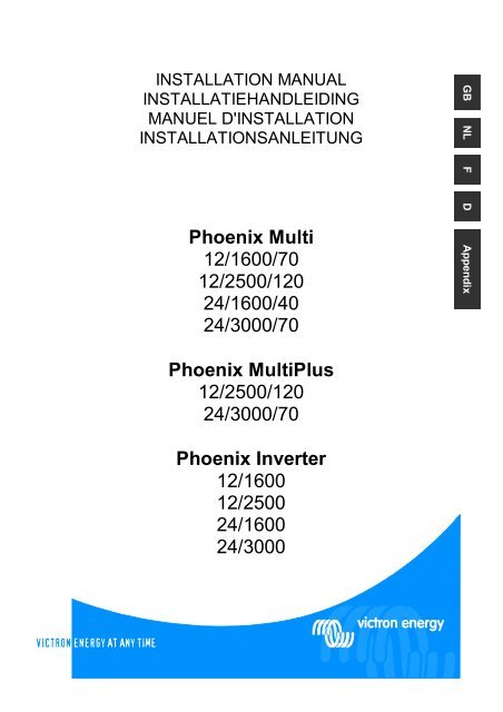
INSTALLATION MANUAL<br />
INSTALLATIEHANDLEIDING<br />
MANUEL D'INSTALLATION<br />
INSTALLATIONSANLEITUNG<br />
<strong>Phoenix</strong> <strong>Multi</strong><br />
12/1600/70<br />
12/2500/120<br />
24/1600/40<br />
24/3000/70<br />
GB NL F D Appendix<br />
<strong>Phoenix</strong> <strong>Multi</strong>Plus<br />
12/2500/120<br />
24/3000/70<br />
<strong>Phoenix</strong> Inverter<br />
12/1600<br />
12/2500<br />
24/1600<br />
24/3000<br />
1
Copyrights © 2003 <strong>Victron</strong> <strong>Energy</strong> B.V.<br />
All Rights Reserved<br />
This publication or parts thereof, may not be reproduced in any form, by any method, for any<br />
purpose.<br />
For conditions of use and permission to use this manual for publication in other than the<br />
English language, contact <strong>Victron</strong> <strong>Energy</strong> B.V.<br />
VICTRON ENERGY B.V. MAKES NO WARRANTY, EITHER EXPRESSED OR IMPLIED,<br />
INCLUDING BUT NOT LIMITED TO ANY IMPLIED WARRANTIES OF MERCHANTABILITY<br />
OR FITNESS FOR A PARTICULAR PURPOSE, REGARDING THESE VICTRON ENERGY<br />
PRODUCTS AND MAKES SUCH VICTRON ENERGY PRODUCTS AVAILABLE SOLELY<br />
ON AN “AS IS” BASIS.<br />
IN NO EVENT SHALL VICTRON ENERGY B.V. BE LIABLE TO ANYONE FOR SPECIAL,<br />
COLLATERAL, INCIDENTAL, OR CONSEQUENTIAL DAMAGES IN CONNECTION WITH<br />
OR ARISING OUT OF PURCHASE OR USE OF THESE VICTRON ENERGY PRODUCTS.<br />
THE SOLE AND EXCLUSIVE LIABILITY TO VICTRON ENERGY B.V., REGARDLESS OF<br />
THE FORM OF ACTION, SHALL NOT EXCEED THE PURCHASE PRICE OF THE<br />
VICTRON ENERGY PRODUCTS DESCRIBED HEREIN.<br />
<strong>Victron</strong> <strong>Energy</strong> B.V. reserves the right to revise and improve its products as it sees fit. This<br />
publication describes the state of this product at the time of its publication and may not reflect<br />
the product at all times in the future.
1. INSTALLATION<br />
1.1 Box Contents<br />
This product should be installed by a qualified electrician<br />
• <strong>Phoenix</strong> <strong>Multi</strong>, <strong>Multi</strong>Plus, or Inverter<br />
• User manual.<br />
• Installation manual.<br />
• Bag containing connection items, i.e.:<br />
• Temperature sensor.<br />
• Fuse (Mega fuse).<br />
• Four M8 nuts.<br />
• Four M8 washers.<br />
• Four M8 spring washers.<br />
• Charging current warning sticker.<br />
GB NL F D<br />
1.2 Location<br />
The product must be installed in a dry and well-ventilated area, as close as possible to the<br />
batteries. There should be a clear space of at least 10 cm around the appliance for cooling.<br />
Excessively high ambient temperature will result in the following:<br />
• Reduced service life.<br />
• Reduced charging current.<br />
• Reduced peak capacity, or shutdown of the inverter.<br />
Never position the appliance directly above the batteries.<br />
The product is suitable for wall mounting. The back of the enclosure has holes for wall<br />
mounting purposes, see Appendix B.<br />
The appliance can be mounted horizontally as well as vertically; vertical mounting is preferable.<br />
The vertical position offers optimum cooling.<br />
The interior of the product must remain accessible after installation.<br />
Ensure that the AC and DC input cables are fitted with fuses and circuit breakers. Try and keep<br />
the distance between the product and the battery to a minimum in order to minimize cable<br />
voltage losses.<br />
For safety purposes, this product should be installed in a heat-resistant environment<br />
if it is used with equipment where a substantial amount of power is to be converted.<br />
You should prevent the presence of e.g. chemicals, synthetic components, curtains<br />
or other textiles, etc., in the immediate vicinity.<br />
1
1.3 Requirements<br />
• Philips screwdriver (PH2) for removing the front.<br />
• Flat screwdriver (0.6x3.5) for connecting the AC leads.<br />
• Insulated box spanner (13 mm) for securing the terminal nuts and the fuse.<br />
• Two battery cables (maximum length 6 meters) including battery terminals and cable ends.<br />
• Three-wire cable.<br />
1.4 Connection of Battery cables<br />
In order to fully utilize the full capacity of the product, batteries with sufficient capacity and<br />
battery cables with sufficient cross section should be used. See table.<br />
Recommended battery capacity<br />
(Ah)<br />
Recommended cross section<br />
(mm 2 )<br />
(0 – 6 m)<br />
12/1600/70 12/2500/120 24/1600/40 24/3000/70<br />
200 – 700 400 – 1200 100 – 400 200 – 700<br />
50 70 35 50<br />
Remark: Internal resistance is the important factor when working with low capacity batteries.<br />
Please consult your supplier or the relevant sections of our book “electricity on board”,<br />
downloadable from our website.<br />
Procedure<br />
Proceed as follows to connect the battery cables:<br />
Use an insulated box spanner in order to avoid shorting the battery.<br />
Avoid shorting the battery cables.<br />
• Undo the four screws at the front of the enclosure and remove the front panel.<br />
• Connect the battery cables: the + (red) on the right and the - (black) on the left, see<br />
Appendix A.<br />
• Reverse polarity connection (+ to – and – to +) will cause the “reversed polarity” LED next<br />
to the terminal nuts to light up.<br />
• Disconnect the cables and reconnect them correctly if the “reversed polarity" LED is<br />
illuminated.<br />
• Tighten the connections after positioning the fastening items supplied with the product.<br />
• Position the Mega fuse from the connection bag in position F4 and secure it, using the<br />
fastening items supplied with the product.<br />
• Secure the nuts tightly in order to reduce the contact resistance as much as possible.<br />
2
1.5 Connection of the AC cabling<br />
The enclosure must be grounded for safety purposes. An earth screw has been<br />
fitted at the bottom side of the enclosure.<br />
The terminal block can be found on the printed circuit board, see Appendix A. The shore or<br />
mains cable must be connected to the <strong>Multi</strong> with the aid of a three-wire cable. Use a three-wire<br />
cable with a flexible core and a cross section of 2.5 or 4 mm²<br />
Procedure<br />
Proceed as follows to connect the AC cables:<br />
• The AC output cable can be connected directly to the terminal block containing the words<br />
"AC-out". The terminal points are indicated clearly. From left to right: “PE” (earth), “N”<br />
(neutral) and “L” (phase).<br />
• The AC input cable can be connected to the terminal block containing the words “AC–in”.<br />
The terminal points are indicated clearly. “PE” (earth) “N” (neutral) and “L” (phase).<br />
GB NL F D<br />
1.6 Optional Connections<br />
A number of optional connections are possible:<br />
1.6.1 Second Battery<br />
The <strong>Phoenix</strong> <strong>Multi</strong>/ <strong>Multi</strong>Plus has a connection for charging a starter battery. For connection see<br />
Appendix A.<br />
1.6.2 Voltage Sense (<strong>Multi</strong>/ <strong>Multi</strong>Plus)<br />
Two sense wires may be connected to compensate possible battery cable losses during<br />
charging. Use wires of at least 0.75mm 2 . For connection see Appendix A.<br />
1.6.3 Temperature Sensor (<strong>Multi</strong>/ <strong>Multi</strong>Plus)<br />
The temperature sensor supplied with the product may be used for temperature-compensated<br />
charging (see Appendix A). The sensor is insulated and must be mounted on the batteries<br />
minus pole.<br />
3
1.6.4 Remote Control<br />
The product can be operated remotely in two ways.<br />
• Use of only an external switch.<br />
• With the aid of a remote control panel.<br />
For connection of the switch see Appendix A.<br />
Observe the following when using only an external switch:<br />
• Only functions if the switch on the product is switched to the "on" position.<br />
• Not to be connected if a remote control panel is connected.<br />
For connection of a remote control panel, see Appendix A.<br />
Observe the following when using a remote control panel:<br />
• Only functions if the switch on the product is switched to the "on" position.<br />
1.6.5 External Relay (<strong>Multi</strong>/ <strong>Multi</strong>Plus)<br />
The maximum current that can be switched through from the AC input to the AC output is 16 A.<br />
At more than 16 A an external contactor is needed: please consult your supplier.<br />
1.6.6 Parallel Connection<br />
The product can be connected in parallel using several identical models, see Appendix G. The<br />
batteries must be connected in accordance with Appendix E or F. This requires interconnecting<br />
the products with the aid of a special cable to be supplied by <strong>Victron</strong> <strong>Energy</strong>, in conjunction with<br />
a connection diagram.<br />
Parallel connection requires compliance with the following conditions:<br />
• No more than five units should be connected in parallel.<br />
• Only identical models should be connected in parallel.<br />
• Ensure sufficient battery capacity is available.<br />
• The prescribed cable cross sections (between battery and distribution point) must be<br />
multiplied with the number of appliances to be connected in parallel.<br />
• Position the products close to each other but ensure there is adequate clearance for<br />
ventilation, min.10 cm.<br />
• The temperature sensor, voltage sensor and remote control must be connected to the<br />
master.<br />
• The cables for each appliance must be equal in length (AC and DC).<br />
1.6.7 3-phase operation multiplus<br />
The <strong>Phoenix</strong> <strong>Multi</strong>Plus can also be used in a 3-phase system, see Appendix 0. The batteries<br />
must be connected in accordance with Appendix E or F. The following conditions should be<br />
complied with in the case of 3-phase operation:<br />
• Only identical models should be used.<br />
• Ensure sufficient battery capacity is available.<br />
• Position the products close to each other but ensure there is adequate clearance for<br />
ventilation (min. 10 cm)<br />
• The temperature sensor and voltage sensor should preferably be connected to all three<br />
products.<br />
• Only a single remote control can be connected, using splitters.<br />
4
2. SETTINGS<br />
• Settings may only be changed by a qualified engineer<br />
• Carefully read the instructions before changes are made.<br />
• When setting the charger, all connections to the battery must be disconnected<br />
from the <strong>Phoenix</strong> <strong>Multi</strong> or <strong>Multi</strong>Plus.<br />
• Do not use non-rechargeable batteries.<br />
• The <strong>Phoenix</strong> <strong>Multi</strong>/ <strong>Multi</strong>Plus default settings are for charging Sonnenschein<br />
Dryfit A200 gel batteries. For the recommended battery voltage see section<br />
2.4.<br />
• Batteries should be placed in a dry and well-ventilated area during charging.<br />
2.1 Settings – General<br />
Settings may be changed with the aid of pushbuttons and dip switches (see Appendix A).<br />
Dipswitches are used to activate set-up, and to determine the setting to be changed. The value<br />
of this setting can be changed with the aid of the pushbuttons.<br />
The value specified is shown on the LEDs. Sections 2.1.3 and 2.1.4 describe how the LEDs<br />
can be read.<br />
GB NL F D<br />
2.1.1 Default Settings<br />
To restore the default settings, both pushbuttons should be held down for 3 seconds while setup<br />
is activated.<br />
Activate Set-up<br />
DS-8<br />
DS-7<br />
DS-6<br />
DS-5<br />
DS-4<br />
DS-3<br />
DS-2<br />
DS-1<br />
on<br />
DS-8<br />
DS-7<br />
DS-6<br />
DS-5<br />
DS-4<br />
DS-3<br />
DS-2<br />
DS-1<br />
DS-8<br />
DS-7<br />
DS-6<br />
DS-5<br />
DS-4<br />
DS-3<br />
DS-2<br />
DS-1<br />
DS-8<br />
DS-7<br />
DS-6<br />
DS-5<br />
DS-4<br />
DS-3<br />
DS-2<br />
DS-1<br />
off<br />
Activate set-up with<br />
DS8 switched to On<br />
Select a setting using<br />
DS3 - DS7 and set<br />
the new value using<br />
the pushbuttons.<br />
DS-1 and DS-2 are not used and must be switched to Off.<br />
Store the settings by<br />
changing the position<br />
of one of the switches<br />
DS3-DS7<br />
Close set-up by<br />
switching DS8 to Off<br />
NOTE: The new value is stored by changing the position of one of the switches DS3-DS7. The<br />
new value is NOT stored if set-up is closed without changing the position of one of the switches<br />
DS3-DS7. This offers an escape route if the change is not to be implemented.<br />
5
2.1.2 Reading LEDs – setting values (<strong>Multi</strong>/ <strong>Multi</strong>Plus)<br />
The value of a setting can be determined on the basis of the following formula:<br />
Value set = setting number * scale + offset<br />
The ‘offset’ and the ‘scale’ are specified for each setting.<br />
The setting number is indicated as follows via the LEDs:<br />
The LEDs are divided into 2 columns of 4 LEDs each.<br />
Each column indicates the numbers 0 - 9.<br />
These columns together indicate 2-digit numbers.<br />
The left column indicates the left-hand digit. The right-hand column shows the righthand<br />
digit.<br />
The digit in a column can be determined by adding the separate ‘LED values’.<br />
A flashing LED counts as 1 and an illuminated LED as 2.<br />
A special case is 4 flashing LEDs. This signifies a 9.<br />
Symbol Meaning LED value<br />
LED off 0<br />
LED flashes 1<br />
LED lit up 2<br />
All LEDs in a<br />
column are<br />
flashing<br />
9<br />
Examples of setting numbers:<br />
0 0 0 1 0<br />
0 2 0 2 0<br />
0 2 2 2 1<br />
0 2 2 2 2<br />
0 6 =6 4 7 =47 3 9 =39<br />
The increments can be smaller than the reading (scale value). In that case, a pushbutton<br />
should be pressed repeatedly before the LED indication changes.<br />
6
2.1.3 Reading LEDs – on-off (<strong>Multi</strong>/ <strong>Multi</strong>Plus)<br />
In addition to the facility of setting a value, there is an on- off facility. This allows for switching<br />
on/ off a particular setting, or for activating/ deactivating it. The left-hand column offers<br />
possibility A and the right-hand column offers possibility B in the case of a dual choice setting.<br />
A B A B<br />
=A =B<br />
The default setting is always A.<br />
The definitions for A and B are shown with the value to be set.<br />
GB NL F D<br />
2.1.4 Default settings<br />
System frequency<br />
50 Hz<br />
Inverter Voltage<br />
230 Vac<br />
Charger on/ off<br />
on<br />
Charger characteristic<br />
Adaptive with battery protection mode<br />
Charging Current<br />
75% of maximum charging current<br />
Battery Type Presets type 1<br />
Absorption Voltage<br />
14.4/ 28.8 Vdc<br />
Absorption Time/ Maximum Absorption Time 4 hours<br />
Float Voltage<br />
13.8/ 27.6 Vdc<br />
Repeated Absorption Time<br />
1 hour<br />
Repeated Absorption Interval<br />
7 days<br />
Bulk Protection On/ Off<br />
on<br />
Mains Waveform Check<br />
on<br />
Generator/ Shore Current<br />
16 A<br />
Generator/ Shore Support<br />
off<br />
3-phase Setting<br />
off<br />
Master/ slave<br />
slave<br />
7
2.2 System Frequency<br />
The product can operate at 50Hz as well as at 60Hz.<br />
Set the DS 3-7 Specify the frequency Example<br />
DS-8<br />
DS-7<br />
DS-6<br />
DS-5 on<br />
DS-4<br />
DS-3<br />
DS-2<br />
DS-1<br />
off<br />
off<br />
off<br />
off<br />
Specify the required frequency.<br />
The default setting is 50Hz.<br />
The left row of LEDs is for 50Hz.<br />
The right row of LEDs is for 60Hz.<br />
Press the buttons until the required<br />
LED indication appears.<br />
Required: frequency is 60Hz.<br />
LED indication =<br />
50Hz 60Hz<br />
2.3 Inverter Settings<br />
Inverter Voltage<br />
The inverter voltage can be set at between 180Vac-245Vac.<br />
Set the DS 3-7 Specify the voltage Example<br />
DS-8<br />
DS-7 on<br />
DS-6 on<br />
DS-5<br />
DS-4<br />
DS-3<br />
DS-2<br />
DS-1<br />
off<br />
off<br />
off<br />
Specify the required voltage Vq.<br />
Determine the setting number:<br />
scale=1V<br />
offset=180V setting<br />
number=(Vq-180)<br />
Determine the LED indication.<br />
Press the pushbuttons until the<br />
required LED indication is displayed.<br />
Required: voltage is 225V.<br />
Setting number = 225-180 = 45.<br />
LED indication =<br />
0 0<br />
0 1<br />
2 2<br />
2 2<br />
4 5<br />
Increment size is 1V.<br />
NOTE: for setting the voltage of the <strong>Phoenix</strong> Inverter a voltage meter is to be used, because the<br />
<strong>Phoenix</strong> Inverter has only 4 LEDs.<br />
8
2.4 Setting the Charger (<strong>Multi</strong>/ <strong>Multi</strong>Plus)<br />
When setting the charger, all connections between the battery and the <strong>Phoenix</strong> <strong>Multi</strong> must be<br />
disconnected.<br />
Please read our book “electricity on board”<br />
(downloadable from our website www. victronenergy.com) for details and suggestions about<br />
charging batteries.<br />
Charger On/ Off<br />
The <strong>Phoenix</strong> <strong>Multi</strong> charger can be switched off if required.<br />
The default is on.<br />
GB NL F D<br />
Set the DS 3-7 Switch the charger on or off Example<br />
DS-8<br />
DS-7 on<br />
DS-6<br />
DS-5<br />
DS-4 on<br />
DS-3<br />
DS-2<br />
DS-1<br />
off<br />
off<br />
off<br />
Determine whether the charger is to<br />
be switched on or off.<br />
The default is On.<br />
The left-hand LED column is for On.<br />
The right-hand LED column is for<br />
Off.<br />
Press the pushbuttons until the<br />
required LED indication is displayed.<br />
Required: charger is off.<br />
LED indication =<br />
On Off<br />
Charging Characteristics<br />
The <strong>Phoenix</strong> <strong>Multi</strong>/ <strong>Multi</strong>Plus has 3 pre-programmed charging characteristics.<br />
Fixed Charging Characteristic:<br />
The absorption period is a fixed preset period. Following the absorption mode, the charger<br />
switches to float. In order to “refresh” the battery, the charger periodically switches back to<br />
absorption.<br />
Adaptive Charging Characteristic:<br />
The absorption period depends on the charge delivered during bulk. This is followed by float<br />
phase lasting 24 hours, after which the voltage is reduced by an additional 0,8 V resp. 1,6 V for<br />
12 V resp. 24 V batteries. (reduced float). As with the Fixed-charging characteristic, the charger<br />
will periodically switch back to absorption.<br />
Adaptive Charging Characteristic with batterySafe mode (default setting):<br />
If, in order to quickly charge a battery, a high charge current in combination with a high<br />
absorption voltage has been chosen, the <strong>Phoenix</strong> charger will prevent damage due to excessive<br />
gassing by automatically limiting the rate of voltage increase once the gassing voltage has been<br />
reached<br />
9
Set the DS 3-7 Set the charging characteristic Example<br />
DS-8<br />
DS-7<br />
DS-6 on<br />
DS-5 on<br />
DS-4 on<br />
DS-3<br />
DS-2<br />
DS-1<br />
off<br />
off<br />
Determine the required charging<br />
characteristic:<br />
1: Fixed<br />
2: Adaptive<br />
3: Adaptive with BatterySafe<br />
mode (default)<br />
Press the pushbuttons until the<br />
required LED indication is displayed.<br />
Required: charging characteristic<br />
is Fixed.<br />
Setting number = 1.<br />
LED indication =<br />
0 0<br />
0 0<br />
0 0<br />
0 1<br />
0 1<br />
Charging Current<br />
The default charging current is 75% of the maximum charging current. This current will be too<br />
high for most applications. For most battery types the optimal charging current is 0.1-0.2x the<br />
battery capacity,<br />
Set the DS 3-7 Set the charging current Example<br />
DS-8<br />
DS-7<br />
DS-6 on<br />
DS-5<br />
DS-4<br />
DS-3<br />
DS-2<br />
DS-1<br />
off<br />
off<br />
off<br />
off<br />
Increment size is 1A.<br />
Determine the required charging<br />
current Iq.<br />
Determine the setting number.<br />
Scale = 2A<br />
Offset = 0A<br />
Setting number = Iq/2<br />
Determine the LED indication.<br />
Press the pushbuttons until the<br />
required LED indication is displayed.<br />
Battery capacity is 450Ah. The<br />
recommended maximum charging<br />
current is 450*0.2 = 90A.<br />
Setting number = 90/2 = 45.<br />
LED indication =<br />
0 0<br />
0 1<br />
2 2<br />
2 2<br />
4 5<br />
10
Battery Type Presets<br />
A number of battery type presets simplify the process of setting the absorption/ float voltage and<br />
maximum absorption time:<br />
Battery type Absorption voltage Float voltage Maximum<br />
absorption<br />
time<br />
0 User-specified<br />
1 Sonnenschein Dryfit A200 Gel 14.4 V 28.8 V 13.8<br />
V/<br />
13.2V<br />
2 Traction 15.0 V 30.0 V 13.8<br />
V/<br />
13.2V<br />
3 Semi-traction 1 14.4 V 28.8 V 14.0<br />
V/<br />
13.2V<br />
4 Victory 1 14.8 V 29.6 V 14.0<br />
V/<br />
13.2V<br />
27.6<br />
V/<br />
26.4V<br />
27.6<br />
V/<br />
26.4V<br />
28.0<br />
V/<br />
26.4V<br />
28.0<br />
V/<br />
26.4V<br />
4 hours<br />
6 hours<br />
5 hours<br />
5 hours<br />
1 The optimal absorption voltage for flat plate lead acid batteries is subject to mechanical and<br />
chemical properties. Batteries with high antimony content can typically be charged with a lower<br />
absorption voltage than batteries with low antimony content, such as the <strong>Victron</strong> carbon fiber<br />
battery. (Please refer to our book “Electricity on Board” downloadable from our website<br />
www.victronenergy.com)<br />
GB NL F D<br />
Set the DS 3-7 Set the battery type Example<br />
DS-8<br />
DS-7 on<br />
DS-6 on<br />
DS-5<br />
DS-4<br />
DS-3 on<br />
DS-2<br />
DS-1<br />
off<br />
off<br />
Determine the battery type used.<br />
Determine the setting numbers with<br />
the aid of the table.<br />
Press the keys until the required LED<br />
indication is displayed.<br />
NOTE: 0 cannot be selected but will<br />
be displayed if the absorption<br />
voltage, the float voltage or the<br />
absorption time is changed.<br />
Required: the battery type is<br />
Victory:<br />
Setting number = 4.<br />
LED indication =<br />
0 0<br />
0 0<br />
0 2<br />
0 2<br />
0 4<br />
The default setting is the Sonnenschein Dryfit A200 battery. Contact your battery supplier for<br />
the correct charge voltages and change the voltage settings if required.<br />
11
Absorption Voltage<br />
The absorption voltage can be set at 12-16/ 24-32V. Battery, the T-sense and V-sense must be<br />
disconnected during setting.<br />
Set the DS 3-7 Set the absorption voltage Example<br />
DS-8<br />
DS-7<br />
DS-6<br />
DS-5<br />
DS-4<br />
DS-3<br />
DS-2<br />
DS-1<br />
off<br />
off<br />
off<br />
off<br />
off<br />
Increment size is 0.05 V.<br />
Determine the required absorption<br />
voltage Vq.<br />
Determine the setting number.<br />
Scale = 0.1V<br />
Offset = 12/24V<br />
Setting number = (Vq-<br />
24)/0,1<br />
Determine the LED indication.<br />
Press the pushbuttons until the<br />
required LED indication is displayed.<br />
Required: absorption voltage is<br />
28.5V.<br />
Setting number= (28.5-24)/0.1 =<br />
45.<br />
LED indication =<br />
0 0<br />
0 1<br />
2 2<br />
2 2<br />
4 5<br />
Absorption Time/ Maximum Absorption Time<br />
This setting defines the absorption period in the case of the fixed charging characteristic and<br />
the maximum absorption time in the case of the adaptive charging characteristic.<br />
The (maximum) absorption time can be set from 1 to 8 hours.<br />
Set the DS 3-7 Set the (maximum) absorption time Example<br />
DS-8<br />
DS-7 on<br />
DS-6<br />
DS-5 on<br />
DS-4 on<br />
DS-3<br />
DS-2<br />
DS-1<br />
off<br />
off<br />
Increments are 1 hour.<br />
Determine the required (maximum)<br />
absorption time Tq.<br />
Determine the setting number.<br />
Scale = 1 hour<br />
Offset = 0<br />
Setting number = Tq<br />
Determine the LED indication.<br />
Press the pushbuttons until the<br />
required LED indication is displayed.<br />
Required: (maximum) absorption<br />
time is 4 hours.<br />
Setting number = 4.<br />
LED indication =<br />
0 0<br />
0 0<br />
0 2<br />
0 2<br />
0 4<br />
12
Float Voltage<br />
The float voltage can be set at 12-16/ 24-32V. Battery, the T-sense and V-sense must be<br />
disconnected during setting.<br />
Set the DS 3-7 Set the float voltage Example<br />
DS-8<br />
DS-7 on<br />
DS-6<br />
DS-5<br />
DS-4<br />
DS-3<br />
DS-2<br />
DS-1<br />
off<br />
off<br />
off<br />
off<br />
Determine the required float voltage<br />
Vq.<br />
Determine the setting number.<br />
Scale = 0.1V<br />
Minimum = 12/24V<br />
Setting number = (Vq-<br />
24)/0,1<br />
Determine the LED indication.<br />
Press the pushbuttons until the<br />
required LED indication is displayed.<br />
Required: float voltage is 28.5V.<br />
Setting number= (28.5-24)/0.1 =<br />
45.<br />
LED indication =<br />
0 0<br />
0 1<br />
2 2<br />
2 2<br />
4 5<br />
GB NL F D<br />
Increment size is 0.05 V.<br />
Repeated Absorption<br />
After each charging cycle, the charger will be switched back to the high charging current after a<br />
pre-set time, following the float phase. This switch back action is called "repeated absorption<br />
mode", see Appendix C.<br />
Repeated Absorption Time<br />
The repeated absorption time can be set at 1 – 72 quarters of an hour.<br />
Set the DS 3-7 Set the repeated absorption time Example<br />
DS-8<br />
DS-7 on<br />
DS-6 on<br />
DS-5 on<br />
DS-4<br />
DS-3<br />
DS-2<br />
DS-1<br />
off<br />
off<br />
Increment size is a quarter of an hour.<br />
Determine the required Repeated<br />
absorption time Tq in quarters of an<br />
hour.<br />
Determine the setting number.<br />
Scale = 1 quarter of an hour<br />
Offset = 0<br />
Setting number = Tq<br />
Determine the LED indication.<br />
Press the pushbuttons until the<br />
required LED indication is displayed.<br />
Required: Repeated absorption<br />
time is 1 hour.<br />
Setting number = 1 hour = 4<br />
quarters of an hour<br />
LED indication =<br />
0 0<br />
0 0<br />
0 2<br />
0 2<br />
0 4<br />
13
Repeated Absorption Interval<br />
The repeated absorption interval, can be set at 1 – 45 days.<br />
Set the DS 3-7 Set the repeated absorption interval Example<br />
DS-8<br />
DS-7<br />
DS-6<br />
DS-5<br />
DS-4 on<br />
DS-3<br />
DS-2<br />
DS-1<br />
off<br />
off<br />
off<br />
off<br />
Increments are 1 day.<br />
Determine the required reduced float<br />
time Tq.<br />
Determine the setting number.<br />
Scale = 1 day<br />
Offset = 0<br />
Setting number = Tq<br />
Determine the LED indication.<br />
Press the pushbuttons until the<br />
required LED indication is displayed.<br />
Required: reduced float time is 1<br />
week.<br />
Setting number = 7.<br />
LED indication =<br />
0 1<br />
0 2<br />
0 2<br />
0 2<br />
0 7<br />
14
2.5 Special Settings<br />
Bulk Protection On/ Off<br />
If the charger has not reached the absorption voltage after 10 hours' charging in the bulk phase,<br />
the battery may be defective. In order to prevent further damage, the charger will automatically<br />
cut out after 10 hours' bulk. The “bulk” LED will start to flash.<br />
This safety cut out can be switched off.<br />
Set the DS 3-7 Switch the bulk cut-out to on or off Example<br />
DS-8<br />
DS-7<br />
DS-6 on<br />
DS-5<br />
DS-4 on<br />
DS-3<br />
DS-2<br />
DS-1<br />
off<br />
off<br />
off<br />
Determine whether the bulk cut out<br />
should be switched on or off.<br />
The default is On.<br />
The left-hand LED column is for On.<br />
The right-hand LED column is for<br />
Off.<br />
Press the pushbuttons until the<br />
required LED indication is displayed.<br />
Required: bulk cut out is off.<br />
LED indication =<br />
On Off<br />
GB NL F D<br />
Mains Waveform Check<br />
The <strong>Phoenix</strong> <strong>Multi</strong> checks if the mains voltage has not only the correct voltage, but also the<br />
correct shape. When the <strong>Phoenix</strong> <strong>Multi</strong> does not function properly on a generator this function<br />
can be disabled.<br />
Set the DS 3-7<br />
Switch the Mains Voltage Check to<br />
on or off<br />
Example<br />
DS-8<br />
DS-7<br />
DS-6 on<br />
DS-5<br />
DS-4<br />
DS-3 on<br />
DS-2<br />
DS-1<br />
off<br />
off<br />
off<br />
Determine whether the Mains<br />
Waveform Check should be switched<br />
on or off.<br />
The default is On.<br />
The left-hand LED column is for On.<br />
The right-hand LED column is for<br />
Off.<br />
Press the pushbuttons until the<br />
required LED indication is displayed.<br />
Required: Mains Waveform<br />
Check is off.<br />
LED indication =<br />
On Off<br />
15
PowerControl – Dealing with limited generator or shore side power<br />
The <strong>Multi</strong> is a very powerful battery charger. It will therefore draw a lot of current from the<br />
generator or shore side supply (nearly 10 A per <strong>Multi</strong> at 230 VAC). With the <strong>Phoenix</strong> <strong>Multi</strong><br />
Control Panel (PMC) a maximum generator or shore current can be set. The <strong>Multi</strong> will then take<br />
account of other AC loads and use whatever is extra for charging, thus preventing the generator<br />
or shore supply from being overloaded.<br />
It is also possible to set the max. generator/ shore current internally.<br />
The generator/ shore current can be set at 1 - 16A.<br />
Set the DS 3-7 Set the shore current Example<br />
DS-8<br />
DS-7<br />
DS-6 on<br />
DS-5 on<br />
DS-4<br />
DS-3<br />
DS-2<br />
DS-1<br />
off<br />
off<br />
off<br />
Increment size is 1A.<br />
Determine the required shore current<br />
limitation Iq.<br />
Determine the setting number.<br />
Scale = 1A<br />
Offset = 0<br />
Setting number = (Iq)/1<br />
Determine the LED indication.<br />
Press the pushbuttons until the<br />
required LED indication is displayed.<br />
Required: shore current limitation<br />
is 16A.<br />
Setting number = 16.<br />
LED indication =<br />
0 0<br />
0 2<br />
0 2<br />
1 2<br />
1 6<br />
The remote control panel setting overrides the internal setting.<br />
PowerAssist – Boosting the capacity of shore or generator power<br />
The feature that distinguishes the <strong>Phoenix</strong> <strong>Multi</strong>Plus from the standard <strong>Multi</strong> is PowerAssist.<br />
This feature takes the principle of PowerControl to a further dimension allowing the <strong>Multi</strong>Plus to<br />
supplement the capacity of the alternative source. Where peak power is so often required only<br />
for a limited period, it is possible to reduce the size of generator needed or conversely enable<br />
more to be achieved from the typically limited shore connection. When the load reduces, the<br />
spare power is used to recharge the battery.<br />
Note: minimum shore current 4 A or generator capacity 2,5 kW required per <strong>Multi</strong>Plus.<br />
16
Set the DS 3-7<br />
DS-8<br />
DS-7 on<br />
DS-6<br />
DS-5 on<br />
DS-4<br />
DS-3<br />
DS-2<br />
DS-1<br />
off<br />
off<br />
off<br />
Switch the generator support on or<br />
off<br />
Determine whether the generator<br />
support should be on or off.<br />
The default is Off.<br />
The left-hand LED column is for Off.<br />
The right-hand LED column is for<br />
On.<br />
Press the pushbuttons until the<br />
required LED indication is displayed.<br />
Example<br />
Required: generator support is on.<br />
LED indication =<br />
Off On<br />
GB NL F D<br />
17
3-phase Setting <strong>Multi</strong>Plus<br />
Three identical units can t be interconnected for a 3-phase system, in accordance with<br />
Appendix 0. The batteries must be connected in accordance with Appendix E or F. A number of<br />
settings are then required for each unit.<br />
Firstly, all units must be set for 3-phase operation.<br />
Set the DS 3-7 Switch 3-phase operation on or off Example<br />
DS-8<br />
DS-7 on<br />
DS-6 on<br />
DS-5<br />
DS-4 on<br />
DS-3<br />
DS-2<br />
DS-1<br />
off<br />
off<br />
Determine whether 3-phase<br />
operation should be on or off.<br />
The default is Off.<br />
The left-hand LED column is for Off.<br />
The right-hand LED column is for<br />
On.<br />
Press the pushbuttons until the<br />
required LED indication is displayed.<br />
Required: 3-phase operation is<br />
on.<br />
LED indication =<br />
Off On<br />
One of the three units must be set as the "master" following this setting.. No further settings are<br />
required for the other units.<br />
Set the DS 3-7 Set the master/ slave Example<br />
DS-8<br />
DS-7<br />
DS-6<br />
DS-5 on<br />
DS-4 on<br />
DS-3<br />
DS-2<br />
DS-1<br />
off<br />
off<br />
off<br />
Determine master or slave.<br />
The default is slave.<br />
The left-hand LED column is for<br />
slave.<br />
The right-hand LED column is for the<br />
master.<br />
Press the pushbuttons until the<br />
required LED indication is displayed.<br />
Required: this unit is the master.<br />
LED indication =<br />
slave master<br />
2.6 Maintenance<br />
The <strong>Phoenix</strong> <strong>Multi</strong> does not require specific maintenance. Annual checking of all connections<br />
and eventually removal of dust suffices. Protect the product from humidity and oil fumes and<br />
keep it as clean as possible.<br />
18
3. TROUBLE SHOOTING TABLE<br />
Proceed as follows for quick detection of common faults.<br />
DC loads must be disconnected from the batteries and the AC loads must be disconnected<br />
from the inverter before the inverter and/ or battery charger is tested.<br />
Consult your <strong>Victron</strong> <strong>Energy</strong> dealer if the fault cannot be resolved.<br />
Problem Cause Solution<br />
The inverter fails to<br />
operate when<br />
switched on.<br />
The “low battery”<br />
LED flashes.<br />
The “low battery”<br />
LED on.<br />
The “overload”<br />
LED flashes.<br />
The “overload”<br />
LED on.<br />
The “temperature”<br />
LED flashes or is<br />
on.<br />
The “low battery”<br />
and “overload”<br />
LEDs flash<br />
alternately.<br />
The “low battery”<br />
and “overload”<br />
LEDs flash<br />
simultaneously.<br />
The “low battery”<br />
and “overload”<br />
LEDs are on.<br />
One LED alarm is<br />
on and the second<br />
LED is flashing<br />
The battery voltage is too high or<br />
too low.<br />
The battery voltage is low.<br />
The inverter cuts out because the<br />
battery voltage is too low.<br />
The load on the inverter is higher<br />
than the nominal load.<br />
The inverter cuts out due to<br />
excessive load.<br />
The ambient temperature is too<br />
high, or the load is excessive.<br />
Low battery voltage and excessive<br />
load.<br />
Voltage ripple on the DC input<br />
exceeds 1.25Vrms.<br />
The inverter cuts out as a result<br />
of excessive voltage ripple on the<br />
DC input.<br />
The inverter cut out as a result of<br />
the illuminated alarm indication<br />
(LED). The flashing LED<br />
indicates that the inverter nearly<br />
cut out as a result of the relevant<br />
alarm.<br />
Ensure that the battery voltage is<br />
within the correct value.<br />
Charge the battery or check the<br />
battery connections.<br />
Charge the battery or check the<br />
battery connections.<br />
reduce the load.<br />
reduce the load.<br />
Place the inverter in a cool and<br />
well-ventilated room, or reduce<br />
the load.<br />
Charge the batteries, reduce the<br />
load or install batteries with a<br />
higher capacity. Use shorter<br />
and/ or thicker battery cables.<br />
Check the battery cables and<br />
terminals.<br />
Check the battery capacity;<br />
increase if necessary.<br />
Install batteries with a higher<br />
capacity. Use shorter and/ or<br />
thicker battery cables and reset<br />
the inverter (switch off and on<br />
again).<br />
Check the table for the<br />
appropriate course of action.<br />
GB NL F D<br />
19
Problem Cause Solution<br />
The charger is not<br />
functioning<br />
The battery is not<br />
being charged fully.<br />
The battery is<br />
overcharged.<br />
The mains voltage or mains<br />
frequency is out of range.<br />
The thermal circuit breaker has<br />
tripped.<br />
Incorrect charging current.<br />
A defective battery connection.<br />
The absorption voltage has been set<br />
to an incorrect value.<br />
The float voltage has been set to an<br />
incorrect value.<br />
The DC fuse is defective.<br />
The absorption voltage has been set<br />
to an incorrect value.<br />
The float voltage has been set to an<br />
incorrect value.<br />
A defective battery.<br />
Ensure that the mains voltage is<br />
between 185 Vac and 265 Vac,<br />
and that the frequency matches<br />
the setting.<br />
Reset the 16 A thermal circuit<br />
breaker.<br />
Set the charging current at<br />
between 0.1 and 0.2x battery<br />
capacity.<br />
Check the battery terminals.<br />
Adjust the absorption voltage to the<br />
correct value.<br />
Adjust the float voltage to the<br />
correct value.<br />
Replace the DC fuse.<br />
Adjust the absorption voltage to the<br />
correct value.<br />
Adjust the float voltage to the<br />
correct value.<br />
Replace the battery.<br />
The battery is too small.<br />
The battery is too hot.<br />
Reduce the charging current or<br />
use a battery with a higher<br />
capacity.<br />
Connect a temperature sensor.<br />
20
4. TECHNICAL DATA<br />
<strong>Phoenix</strong> 12/1600/70 12/2500/120 24/1600/40 24/3000/70<br />
INVERTER and <strong>Multi</strong>/ <strong>Multi</strong>Plus<br />
Input voltage range (V DC) 9,5-16,1 9,5-16,1 19,0-32,2 19,0-32,2<br />
Output voltage (V AC) 230 ± 2%<br />
Frequency (Hz) 50 ± 0,1%<br />
Cont. output power at 25 °C (VA) 1600 2500 1600 3000<br />
Cont. output power at 25 °C (W) 1300 2000 1300 2500<br />
Cont. output power at 40 °C (W) 1100 1600 1200 2000<br />
Peak power (W) 2300 4500 3000 6000<br />
Maximum efficiency (%) 93 93 94 94<br />
Zero-load (economy) power (W) 6 6 6 6<br />
CHARGER (<strong>Multi</strong>/ <strong>Multi</strong>Plus only)<br />
Input voltage range (V AC) 187-265<br />
Frequency (Hz) 50 ± 0,1%<br />
Power factor 1<br />
Charge voltage 'absorption' (V DC) 14,4 14,4 28,8 28,8<br />
Charge voltage 'float' (V DC) 13,8 13,8 27,6 27,6<br />
Storage mode (V DC) 13,2 13,2 26,4 26,4<br />
Charge current house batt. (A) 70 120 40 70<br />
GB NL F D<br />
Charge current starter batt. (A) 4 4 4 4<br />
Battery capacity (Ah) 200-700 400-1200 100-400 200-700<br />
Temperature sensor √ √ √ √<br />
GENERAL<br />
Forced cooling √ √ √ √<br />
Protection (2)<br />
a – h<br />
Operating temp. range 0 - 50°C<br />
Humidity (non condensing) max 95%<br />
ENCLOSURE<br />
Material & Colour aluminium (blue RAL 5012)<br />
Battery-connection<br />
M8 bolts<br />
230 V AC-connection screw-clamp 2,5 mm²<br />
Protection category IP 21<br />
Weight (kg) 12 18 12 18<br />
Dimensions (H x W x D in mm)<br />
362x258x218<br />
STANDARDS<br />
Safety EN 60335-1, EN 60335-2-29<br />
Emission EN 50081-1, EN55014, EN 61000-3-2, EN 61000-3-3<br />
Immunity EN 55014-2<br />
Automotive Directive<br />
95/54/EC<br />
21
5. APPENDIX<br />
A Overview connections<br />
I<br />
H<br />
B<br />
J<br />
GB NL F D Appendix<br />
K<br />
L<br />
TR-<br />
V-SENSE T-SENSE<br />
+ - + - + -<br />
G<br />
A D E M F
A Shore supply. AC in: (left to right) PE (ground), N (neutral), L (phase).<br />
B Connector for remote panel.<br />
C Load connection. AC out: (left to right) PE (ground), N (neutral), L (phase).<br />
D Megafuse F4.<br />
E Battery minus.<br />
F Battery plus.<br />
G Terminals for: (left to right) Voltage sense plus, Voltage sense minus, Starter battery plus,<br />
Starter battery minus, Temperature sensor plus, Temperature sensor minus.<br />
H Connections for remote switch: Short left and middle terminal to switch the <strong>Multi</strong> “on”, Short<br />
right and middle terminal to switch the <strong>Multi</strong> to “charger only”.<br />
I Dipswitches DS1 tm DS8 for set-up mode.<br />
J Pushbuttons for set-up mode.<br />
K Used for Parallel and 3-Phase operation, J7 IN.<br />
L Used for Parallel and 3-Phase operation, J8 OUT.<br />
M “Reversed polarity” LED.<br />
2
B Dimensions<br />
GB NL F D<br />
3
C Charge characteristics<br />
Charge current<br />
120%<br />
100%<br />
80%<br />
Am ps<br />
60%<br />
40%<br />
20%<br />
0%<br />
Tim e<br />
32<br />
30<br />
28<br />
26<br />
Volts<br />
16<br />
15<br />
14<br />
13<br />
Charge voltage<br />
Battery Safe<br />
mode<br />
5 x Bulk-hours or<br />
Max. Absorption time<br />
24<br />
22<br />
12<br />
11<br />
10<br />
Tim e<br />
Bulk hours<br />
Absorption<br />
1 day<br />
float<br />
7 days<br />
reduced float<br />
7 days<br />
reduced float<br />
1 hour Repeated Absorption<br />
4-stage charging:<br />
Bulk-mode: Entered when charger is started. Constant current is applied until nominal battery voltage is reached,<br />
depending on temperature and input voltage, after which constant power is applied up to the point where excessive<br />
gassing is starting (14.4V resp. 28.8V, temperature compensated).<br />
Battery Safe Mode: The applied voltage to the battery is raised gradually until the set Absorption voltage is reached. The<br />
Battery Safe Mode is part of the calculated absorption time.<br />
Absorption-mode: Absorption voltage is applied until {actual-Bulk-Ah*5 / max.adjusted-Bulk-current} (in hours) is<br />
reached. Usually {actual-Bulk-Ah*5} = {max.adjusted-Bulk-current * Bulk-hours *5}, but the actual-Bulk-current can be<br />
limited by ambient temperature, or remote control. The maximum time in Absorption mode is the Maximum Absorption<br />
time set.<br />
Float-mode: Float voltage is applied to keep the battery fully charged and to protect it against self-discharge.<br />
Reduced Float: After one day of Float charge a reduced Float charge is applied. This is 13,2V resp. 26,4V (for 12V and<br />
24V charger). This will limit water loss to a minimum when the battery is stored for the winter season.<br />
After an adjustable time (default = 7 days) the charger will enter Repeated Absorption-mode for an adjustable time<br />
(default = 4 quarters).<br />
4
D Temperature compensation<br />
Volts<br />
15.0<br />
14.5<br />
14.0<br />
13.5<br />
13.0<br />
12.5<br />
12.0<br />
11.5<br />
11.0<br />
10.5<br />
10.0<br />
0 5 10 15 20 25 30 35 40 45 50 55 60<br />
30<br />
29<br />
28<br />
27<br />
26<br />
25<br />
24<br />
23<br />
22<br />
21<br />
20<br />
Volts<br />
GB NL F D<br />
Battery temperature<br />
Default output voltages for Float and Absorption are at 20°C. Reduced Float voltage follows<br />
Float voltage and Raised Absorption voltage follows Absorption voltage. In adjust mode<br />
temperature compensation does not apply.<br />
5
E Star connect schematic<br />
_ + _ + _ +<br />
Length La=Lb=Lc<br />
Length Ld=Le=Lf<br />
La<br />
Lb<br />
Lc<br />
_<br />
+<br />
F1<br />
Ld<br />
Le<br />
Lf<br />
F2<br />
F3<br />
F4<br />
F Rail connect schematic<br />
_ + _ + _ +<br />
Length La=Lb=Lc<br />
Length Ld=Le=Lf<br />
La<br />
Ld<br />
Lb<br />
Le<br />
Lc<br />
Lf<br />
F2 F3 F4<br />
_<br />
+<br />
F1<br />
6
G Parallel connect schematic<br />
remote<br />
control<br />
GB NL F D<br />
AC in<br />
L in<br />
N in<br />
PE<br />
L out<br />
N out<br />
PE<br />
AC out<br />
3-Phase connect schematic<br />
remote<br />
control<br />
AC in<br />
L1<br />
L2<br />
L3<br />
N in<br />
PE<br />
L1<br />
L2<br />
L3<br />
N out<br />
PE<br />
AC out<br />
7
Serial number:<br />
Distributor:<br />
<strong>Victron</strong> <strong>Energy</strong> B.V.<br />
The Netherlands<br />
General phone: +31 (0)36 535 97 00<br />
Customer support desk: +31 (0)36 535 97 77<br />
General and Service fax: +31 (0)36 531 16 66<br />
Sales fax: +31 (0)36 535 97 40<br />
E-mail:<br />
Internet site:<br />
sales@victronenergy.com<br />
http://www.victronenergy.com<br />
Article number:<br />
ISM010054000<br />
Version: 00<br />
Date: 01-01-2003<br />
8