
You also want an ePaper? Increase the reach of your titles
YUMPU automatically turns print PDFs into web optimized ePapers that Google loves.
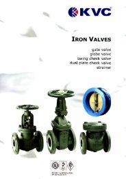
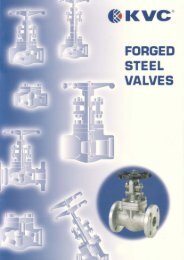
FORWARD<br />
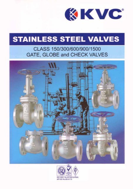
We take the pleasure in presenting our production of KVC ® Stainless Steel Gate, Globe and Swing<br />
Check Valves.<br />
KVC ® Stainless Steel Valves are widely used in the petroleum refineries and chemical processing<br />
industries and approved by most major oil and gas companies.<br />
KVC ® Stainless Steel Valves are designed and manufactured in strict accordance with the<br />
prescriptions and requirement of ASTM, ANSI, API, BS standards to meet the applicable-standards,<br />
in addition to KVC Co., Ltd's own ISO 9000-2000 procedure for quality control.<br />
Our basic policy for quality assurance is to manufacture products of excellent quality to obtain great<br />
trust and deep satisfaction of customers and to thoroughly assure this quality.
Index<br />
Index<br />
Figure Number<br />
Page l<br />
Page 2<br />
Gate Valve Page 3<br />
ANSI 150 Fig. 0113F Page 4 & 5<br />
ANSI 300 Fig. 0313F Page 6 & 7<br />
Gate Valve ANSI 600 Fig. 0613F_ Page 8<br />
ANSI 900 Fig. 0913F Page 9<br />
ANSI 1500 Fig. 1513F Page10<br />
Globe Valve Page 11<br />
ANSI 150 Fig. 0123F Page 12<br />
ANSI 300 Fig. 0323F Page 13<br />
Globe Valve ANSI 600 Fig. 0623F Page 14<br />
ANSI 900 Fig. 0923F Page 15<br />
ANSI 1500 Fig. 1523F Page 16<br />
Swing Check Valve Page 17<br />
ANSI 150 Fig. 0133F Page 18<br />
ANSI 300 Fig. 0333F Page 19<br />
Swing Check Valve ANSI 600 Fig. 0633F Page 20<br />
ANSI 900 Fig. 0933F Page 21<br />
ANSI 1500 Fig. 1533F Page 22<br />
Electrically / Gear operated Valves<br />
Welding End Details<br />
Reference Standards and Specification<br />
Comparison List for Casting and Forging<br />
Chemical and Physical Properties<br />
Steel Pipe Flanges<br />
Valve Wall Thickness<br />
Pressure Temperature Rating<br />
Optional Material<br />
Packing Material and Construction<br />
Gasket Material and Construction<br />
Terms and Condition of Sale<br />
Page 23<br />
Page 24<br />
Page 25<br />
Page 26<br />
Page 27<br />
Page 28 & 29<br />
Page 30<br />
Page 31<br />
Page 32<br />
Page 33<br />
Page 34 & 35<br />
Page 36<br />
We reserve the right to institute changes in any materials, designs and specification within this catalogue.<br />
1
FIGURE NUMBER<br />
How To Specify<br />
Example: -<br />
Fig. 101 1 3 F - 10<br />
Ansi Rating Valve Body / Bonnet End Connection Seating Trim<br />
Type<br />
Material<br />
ANSI Rating Valve Type Body / Bonnet Material End Connection<br />
01= ANSI 150 0= Plug 1 = Low Carbon Steel - ASTM A352 LCB / LC31 LCC B = Bevel Weld<br />
03 = ANSI 300 1=Gate 2 = Carbon Steel - ASTM A216 Gr.WCB F = Raised Face Flange<br />
06 = ANSI 600 2=Globe 3 = Stainless Steel - ASTM A351 CF8M / CF3M R = Ring Type Joint<br />
09 = ANSI 900 3=Swing 4 = Stainless Steel - ASTM A351 CF8 / CF3 / CF10<br />
15 = ANSI 1500 5 = Stainless Steel - ASTM A351 CF8C (Type 347)<br />
25 = ANSI 2500* 6 = Stainless Steel - ASTM A351 CG8M / CG3M<br />
7 = Alloy Steel - ASTM A217 WC1 / WC6 / WC9 / C5/ C12<br />
*Available on request<br />
8 =Alloy 20 - ASTM A351 CN7M<br />
9 = Duplex Stainless Steel<br />
0 = Hastelloy, Monel or Others<br />
Seating Trim<br />
API Trim No<br />
Trim<br />
Seat Surface<br />
Hardness (Hb a Min.)<br />
Material<br />
2 304<br />
18Cr-8Ni<br />
10 316<br />
18Cr-8Ni<br />
12 316 & Hardfaced<br />
c f & 350 18 Cr-8Ni & Trim 5 or 5A<br />
15 316 (F-Stl) 350 d Co-Cr A h<br />
16 316L (F-Stl) 350 d Co-Cr A h<br />
17 304 (F-Stl)<br />
c f & 350 Co-Cr A h<br />
18 304 & Hardfaced 350 d 18 Cr-8Ni & Co-Cr A h<br />
19 321 (F-Stl)<br />
20 316L<br />
21 347<br />
22 304L<br />
25 316L & Hardfaced<br />
26 321 & Hardfaced<br />
Note:<br />
c<br />
c<br />
c<br />
c<br />
c<br />
c<br />
c f & 350<br />
c f & 350<br />
a HB (formerly HBN) is the symbol for Brinell Hardness per ASTM E10.<br />
Co-Cr A h<br />
16Cr-12Ni-2Mo<br />
18Cr-10Ni-Cb<br />
18Cr-8Ni<br />
16Cr-12Ni-2Mo & Co-CrA h<br />
18Cr-10Ni-Ti & Co-CrA h<br />
c<br />
d<br />
f<br />
Manufacturer’s standard hardness.<br />
Differential hardness between the body and gate seat surfaces is not required.<br />
Hardness differential between body and gate shall be manufacturer’s std.<br />
h This classification includes such trademarked materials as Stellite 6, Stoody 6, and Wallex 6.<br />
2
KVC ® STAINLESS STEEL GATE VALVES<br />
STEM<br />
The stem is in stainless steel and is part of the trim. The stem is<br />
provided with a T-head. A ground backseat is provided to<br />
ensure perfectly tight seal to the stuffing box when the valve is<br />
fully open. The stem is ground to minimize friction and prevent,<br />
damage to gland packing. The threading is trapezoidal ACME<br />
type. Dimensions comply with the applicable standard.<br />
GLAND AND FLANGE<br />
They are in stainless steel and are normally supplied in two<br />
pieces. The contact surfaces between gland and gland flange<br />
have a spherical profile to permit the eyebolts are unevenly<br />
tightened.<br />
YOKE SLEEVE<br />
The yoke sleeve is made from cast aluminum, bronze, stainless<br />
steel or ductile iron having high resistance to wear and a high<br />
melting point. It is designed to permit removal from the bonnet or<br />
the yoke while the valve is in service.<br />
HANDHWEEL<br />
The steel or nodular iron handwheels are well shaped and large<br />
enough to give ease of movement when operating the valve,<br />
even under maximum differential pressure.<br />
SEAT RINGS (If not integral)<br />
The rings are in stainless and are part of the trim. They are<br />
completely threaded outside and notched on their inner surface<br />
to ease installing and dismantling. Special attention is given to<br />
the sealing surface which are ground and lapped for a perfectly<br />
tight seal.<br />
BODY<br />
The body is in stainless steel and is carefully designed in<br />
all its details. The basic dimensions, i.e. wall thickness,<br />
face to face and flanges comply with the relevant API and<br />
ANSI standards. The sealing surfaces for connection to the<br />
bonnet are flat finish in ANSI rating150, recessed in 3001b<br />
class or may be ring joint in the ANSI rating 600 and<br />
above.<br />
The body standard is integral seats and may be threaded<br />
for renewable seats. Bosses may be provided for drain<br />
taps or by-pass piping.<br />
BONNET<br />
The bonnet is in stainless steel. It is machined to accept<br />
the yoke sleeve and incorporates a stuffing box<br />
dimensioned in accordance with the API standard.<br />
WEDGE<br />
The wedge is part of the trim. It is stainless steel. It is<br />
normally supplied as flexible or solid. It is connected to the<br />
stem by means of a T-joint. The guides on each side of the<br />
wedge are machined for proper alignment with the body<br />
guides. Special attention is given to the seating surface<br />
which are ground and lapped to insure a perfectly tight<br />
seal.<br />
BONNET BUSHING (If not integral)<br />
The bonnet bushing or backseat is in forged stainless steel and<br />
forms part of the trim. Special attention is given both to its<br />
machining and heat treatment to insure a proper seat.<br />
LANTERN (not shown)<br />
A lantern ring is fitted to all valves ANSI rating 300 and above. It<br />
is designed to be easily removable for re-packing.<br />
BONNET BOLTING<br />
Bonnet studs and nuts are manufactured from alloy or stainless<br />
steel to the relevant ASTM Standard.<br />
GLAND BOLTS AND NUTS<br />
The forged stainless steel gland bolts are of the eyebolt type<br />
which can be swung outward for ease of gland re-packing. They<br />
are fixed to the bonnet by stud bolts and nuts<br />
3
KVC ® STAINLESS STEEL GATE VALVE - ANSI 150<br />
4
KVC ® STAINLESS STEEL GATE VALVE - ANSI 150<br />
SPECIFICATION<br />
Bolted Bonnet<br />
Outside Screw and Yoke<br />
Solid / Flexible Wedge<br />
Oval Bonnet with integral Yoke<br />
Rising Stem - Non-rising Handwheel<br />
Integral Seat Rings (Standard)<br />
Welded-In / Threaded Seat Rings (Optional)<br />
Full Port<br />
Raised Face Flanged Ends or Butwelding Ends<br />
Gear Operated recommended for size 14" above<br />
APPLICABLE STANDARDS<br />
Design: AP1600<br />
End Flange: ANSI B16.5<br />
Weld Ends: ANSI B16.25<br />
Face-to-Face: ANSI B16.10<br />
Shell and Seat Test: API 598<br />
Parts And Material List<br />
Fig. 0113F<br />
No. Part Name Material ASTM Specification<br />
01 Body Stainless Steel ASTM A351 CF8M<br />
02 Bonnet Stainless Steel ASTM A351 CF8M<br />
04 Wedge Stainless Steel ASTM A351 CF8M<br />
07 Stem Stainless Steel A276 316<br />
09 Yoke Sleeve Ductile Iron A439 D z C<br />
11 Gland Flange Stainless Steel ASTM A351 CF8<br />
12 Packing Gland Stainless Steel A276 316<br />
14 Yoke Cap Stainless Steel A276 304<br />
15 Handwheel Nut Stainless Steel A276 304<br />
18 Handwheel Ductile Iron A536<br />
31 Bonnet Bolt Stainless Steel A193 B8<br />
33 Bonnet Nut Stainless Steel A194 8<br />
34 Gland Bolt Stainless Steel A193 B8<br />
35A Yoke Nut Stainless Steel A194 8<br />
35B Gland Nut Stainless Steel A194 8<br />
36 Hinge Pin Stainless Steel A276 304<br />
41 Set Screw Steel Stainless Steel<br />
46 Key Steel A108 1045 (1-1/2" & larger)<br />
47 Grease Nipple Steel Steel (Cr. Plated)<br />
51 Packing Reinforced Teflon PTFE P#4505L<br />
56 Gasket Reinforced Teflon Sheet PTFE P#4400<br />
73 Thrust Bearing Steel Steel<br />
* N Note : Wedge design - 3" & smaller: solid, 4" and larger: flexible<br />
Size<br />
Face -to-Face<br />
L<br />
Dia. of Bore<br />
d<br />
O.D. of Flange<br />
D<br />
$ of Bolt Circle<br />
C<br />
Dimensional Data (mm)<br />
O.D. of RF<br />
g<br />
7hk of Flange<br />
t<br />
5<br />
Ht. of RF<br />
f<br />
$ of Bop Holes<br />
n-h<br />
~ of Handwheel<br />
O<br />
1f2" 108.0 12.7 88.9 60.5 35.1 11.2 1.6 4-15.8 100 200 3.0 3.4<br />
314" 117.5 19.1 98.6 69.9 42.9 11.2 1.6 4-15.8 100 212 3.1 3.9<br />
1 " 127.0 25.4 108.0 79.2 50.8 11.2 1.6 4-15.8 120 247 4.1 5.3<br />
1-1/2" 165.1 38.1 127.0 98.6 73.2 14.3 1.6 4-15.8 160 303 4.8 9.1<br />
2" 177.8 50.8 152.4 120.7 91.9 15.8 1.6 4-19.1 180 369 5.6 13.8<br />
2-1/2" 190.5 63.5 177.8 139.7 104.6 17.6 1.6 4-19.1 180 408 5.6 19.4<br />
3" 203.2 76.2 190.5 152.4 127.0 19.1 1.6 4-19.1 200 466 5.6 23.6<br />
4" 228.6 101.6 228.6 190.5 157.2 23.9 1.6 8-19.1 225 576 6.4 38.5<br />
5" 254.0 127.0 254.0 215.9 185.7 23.9 1.6 8-22.2 250 648 7.1 47.1<br />
6" 266.7 152.4 279.4 241.3 215.9 25.4 1.6 8-22.2 250 747 7.1 66.3<br />
8" 292.1 203.2 342.9 298.5 269.7 28.4 1.6 8-22.2 300 952 8.1 106.5<br />
10" 330.2 254.0 406.4 362.0 323.9 30.3 1.6 12-25.4 350 1145 8.6 150.3<br />
12" 355.6 304.8 482.6 431.8 381.0 31.8 1.6 12-25.4 400 1349 9.6 215.0<br />
14" 381.0 336.6 533.4 476.3 412.8 35.1 1.6 12-28.4 600 1474 10.4 291.3<br />
16" 406.4 387.4 596.9 539.8 469.9 36.6 1.6 16-28.4 560 1758 11.2 375.0<br />
18" 431.8 438.2 635.0 577.9 533.4 39.7 1.6 16-31.8 560 1910 11.9 518.0<br />
20" 457.2 489.0 698.5 635.0 584.2 43.0 1.6 20-31.8 630 2143 12.7 662.0<br />
24" 508.0 590.6 812.8 749.3 692.2 47.8 1.6 20-35.1 630 2472 14.5 955.0<br />
v<br />
Non-shock pressure rating: 275 PSIG @ -20°F to 100 °F per ANSI B16.34<br />
Height<br />
H<br />
Wall Thk<br />
a min<br />
Wt(Kg)
KVC ® STAINLESS STEEL GATE VALVE - ANSI 300<br />
6
KVC ® STAINLESS STEEL GATE VALVE - ANSI 300<br />
size: 10" -24"<br />
SPECIFICATION<br />
Bolted Bonnet<br />
Outside Screw and Yoke Solid/Flexible Wedge<br />
Rising Stem - Non-rising Handwheel Integral<br />
Seat Rings (Standard)<br />
Welded-In / Threaded Seat Rings (Optional)<br />
Full Port<br />
Raised Face Flanged Ends or Butwelding Ends<br />
Gear Operated recommended for size 14" above<br />
APPLICABLE STANDARDS<br />
Design : API 600<br />
End Flange : ANSI B16.5<br />
Weld Ends : ANSI 16.25<br />
Face-to-Face : ANSI B16.10<br />
Shell and Seat Test : API 598<br />
Parts And Material List<br />
Fig. 0313F<br />
No. Part Name Material ASTM Specification<br />
01 Body Stainless Steel ASTM A351 CF8M<br />
02 Bonnet Stainless Steel ASTM A351 CF8M<br />
04 Wedge Stainless Steel ASTM A351 CF8M<br />
07 Stem Stainless Steel A276 316<br />
09 Yoke Sleeve Ductile Iron A439 D Z C<br />
11 Gland Flange Stainless Steel ASTM A351 CF8<br />
12 Packing Gland Stainless Steel A276 316<br />
14 Yoke Cap Stainless Steel A276 304<br />
15 Handwheel Nut Stainless Steel A276 304<br />
18 Handwheel Ductile Iron A536<br />
31 Bonnet Bolt Stainless Steel A193 B8<br />
33 Bonnet Nut Stainless Steel A194 8<br />
34 Gland Bolt Stainless Steel A193 B8<br />
35A Yoke Nut Stainless Steel A194 8<br />
35B Gland Nut Stainless Steel A194 8<br />
36 Hinge Pin Stainless Steel A276 304<br />
41 Set Screw Steel Stainless Steel<br />
46 Key Steel A108 1045 (1" & larger)<br />
47 Grease Nipple Steel Steel (Cr. Plated)<br />
51 Packing Reinforced Teflon PTFE P#4505L<br />
56 Gasket* (see note) Reinforced Teflon Sheet PTFE P#4400<br />
73 Thrust Bearing Steel Steel<br />
Note : Gasket 10" and above - S.P.W. SS316/PTFE (P#2301-GGO)<br />
Wedge design - 2" & smaller, 3" and above: flexible<br />
Dimensional Data (mm)<br />
Size<br />
Face -to-Face<br />
L<br />
Dia. of Bore<br />
d<br />
O.D. of Flange<br />
D<br />
~ of Bolt Circle<br />
C<br />
O.D. of RF<br />
g<br />
Thk of Flange<br />
t<br />
Ht, of RF<br />
f<br />
~ of Bolt Holes<br />
n-h<br />
~ of Handwheel<br />
O<br />
Height<br />
H<br />
Wall Thk<br />
a min<br />
Wt (Kg)<br />
½” 139.7 12.7 95.3 66.5 35.1 14.3 1.6 4-15.8 100 218 3.1 4.0<br />
¾” 152.4 19.1 19.1 82.6 42.9 15.8 1.6 4-19.1 100 227 3.8 5.3<br />
1” 165.1 25.4 25.4 88.9 50.8 17.6 1.6 4-19.1 180 292 4.8 9.3<br />
1-1/2” 190.5 38.1 155.4 114.3 73.2 20.6 1.6 4-22.2 200 375 4.8 17.0<br />
2” 215.9 50.8 165.1 127.0 91.9 22.2 1.6 8-19.1 200 403 6.4 18.2<br />
3” 282.6 76.2 209.6 168.1 127.0 28.4 1.6 8-22.2 225 469 7.1 41.6<br />
4” 304.8 101.6 254.0 200.2 157.2 31.8 1.6 8-22.2 250 602 7.8 64.1<br />
6” 403.2 152.4 317.5 269.7 215.9 36.6 1.6 12-22.2 350 832 9.6 125.0<br />
8” 419.1 203.2 381.0 330.2 269.7 41.2 1.6 12-25.4 400 1021 11.2 185.0<br />
10” 457.2 254.0 444.5 387.4 323.9 47.8 1.6 16-28.4 450 1228 12.7 272.0<br />
12” 501.7 304.8 520.7 450.9 381.0 50.8 1.6 16-31.8 500 1425 14.2 413.0<br />
14” 762.0 336.6 584.2 514.4 412.8 53.9 1.6 20-31.8 560 1638 15.8 549.0<br />
16” 838.2 387.4 647.7 571.5 469.9 57.2 1.6 20-35.1 560 1784 17.5 822.0<br />
18” 914.4 431.8 711.2 628.7 533.4 60.5 1.6 24-35.1 610 1972 19.0 1030.0<br />
20” 990.6 482.6 774.7 685.8 584.2 63.5 1.6 24-35.1 660 2200 20.6 1293.0<br />
24” 1143.0 584.2 914.4 812.8 692.2 69.9 1.6 24-41.2 660 2553 23.9 2327.0<br />
Non-stock pressure rating: 720 PSIG @ -20°F to 100°F per ANSI B16.34<br />
7
KVC ® STAINLESS STEEL GATE VALVE - ANSI 600<br />
size: 2" -4"<br />
SPECIFICATION<br />
Bolted Bonnet<br />
Outside Screw and Yoke<br />
Flexible Wedge<br />
Rising Stem - Non-rising Handwheel<br />
Integral Seat Rings (Standard)<br />
Welded-In / Threaded Seat Rings (Optional)<br />
Full Port<br />
Raised Face Flanged Ends or Butwelding Ends<br />
Gear Operated recommended for size 8" above<br />
Size: 6" -12"<br />
Size: 6" -12"<br />
APPLICABLE STANDARDS<br />
Design: API 600<br />
End Flange: ANSI 1316.5<br />
Weld Ends: ANSI 1316.25<br />
Face-to-Face: ANSI B16.10<br />
Shell and Seat Test: API 598<br />
Dimensional Date<br />
Size (mm)<br />
Face -to-Face<br />
L<br />
Dia. of Bore<br />
d<br />
O.D. of Flange<br />
D<br />
Ø of Bolt Circle<br />
C<br />
O.D. of RF<br />
g<br />
Thk of Flange<br />
t<br />
Ht. of RF<br />
f<br />
Ø of Bolt Holes<br />
n-h<br />
Ø of Handwheel<br />
O<br />
Height<br />
H<br />
Wall Thk<br />
a min<br />
Wt (Kg)<br />
2" 292.1 50.8 165.1 127.0 91.9 25.4 6.4 8-19.1 200 419 11.2 39.9<br />
2-1/2" 330.2 63.5 190.5 149.4 104.6 28.5 6.4 8-22.2 200 419 11.9 58.0<br />
3" 355.6 76.2 209.6 168.1 127.0 31.8 6.4 8-22.2 250 520 12.7 65.0<br />
4" 431.8 101.6 273.1 215.9 157.2 38.1 6.4 8-25.4 300 635 16.0 101.0<br />
Non-stock pressure rating: 1440 PSIG @ -20°F to 100°F per ANSI B16.34<br />
8
KVC ® STAINLESS STEEL GATE VALVE - ANSI 900<br />
Size: 2” -4”<br />
SPECIFICATION<br />
Bolted Bonnet<br />
Outside Screw and Yoke<br />
Flexible Wedge<br />
Rising Stem - Non-rising Handwheel<br />
Integral Seat Rings (Standard)<br />
Welded-In / Threaded Seat Rings (Optional)<br />
Full Port<br />
Raised Face Flanged Ends, Butwelding Ends<br />
or Ring Joint Ends<br />
Gear Operated recommended for size 4" above<br />
Parts And Material List Fig. 0913F<br />
Size: 6” – 8 ”<br />
APPLICABLE STANDARDS<br />
Design: API 600<br />
End Flanged : ANSI B16.5<br />
Weld Ends : ANSI B16.25<br />
Face-to-Face: ANSI B16.10<br />
Shell and Seat Test: API 598<br />
No. Part Name Material ASTM Specification<br />
01 Body Stainless Steel ASTM A351 CF8M<br />
02 Bonnet Stainless Steel ASTM A351 CF8M<br />
03 Yoke Stainless Steel ASTM A351 CF8<br />
04 Wedge Stainless Steel ASTM A351 CF8M<br />
07 Stem Stainless Steel A276 316<br />
09 Yoke Sleeve Ductile Iron A439 D Z C<br />
11 Gland Flange Stainless Steel ASTM A351 CF8<br />
12 Packing Gland Stainless Steel A276 316<br />
14 Yoke Cap Stainless Steel A276 304<br />
15 Handwheel Nut Stainless Steel A276 304<br />
18 Handwheel Ductile Iron A536<br />
21 Body Seat Ring Stainless Steel A182 F316<br />
23 Back Seat Ring Stainless Steel A182 316<br />
31 Bonnet Bolt Stainless Steel A193 B8<br />
32 Yoke Bolt Stainless Steel A193 B8<br />
33 Bonnet Nut Stainless Steel A194 8<br />
34 Gland Bolt Stainless Steel A193 B8<br />
35/B Gland Nut Stainless Steel A194 8<br />
35A Yoke Nut Stainless Steel A194 8<br />
36 Hinge Pin Stainless Steel A276 304<br />
41 Set Screw Steel Stainless Steel<br />
47 Grease Nipple Steel Steel (Cr. Plated)<br />
51 Packing Graphite + Carbon Fiber P#6610+ #6528<br />
56 Gasket Ring Joint Gasket P#1500G<br />
73 Thrust Bearing Steel Steel<br />
Dimensional Data (mm)<br />
Size<br />
Face 4o-Face<br />
L<br />
Dia. of Bore<br />
d<br />
O.D. of Flange<br />
D<br />
Ø of Bolt Circle<br />
C<br />
O.D. Of RF<br />
g<br />
Thk of Flange<br />
t<br />
Hl. of RF<br />
f<br />
Ø of Bolt Holes<br />
n-h<br />
Ø of Handwheel<br />
O<br />
Height<br />
H<br />
Wall Thk<br />
a min<br />
Wt(Kg)<br />
2" 368.3 47.5 215.9 165.1 91.9 38.1 6.4 8-25.4 250 523 19.1 85.0<br />
2-1 2" 419.1 57.2 244.3 190.5 104.6 41.2 6.4 8-28.4 300 562 22.4 105.0<br />
3' 381.0 72.9 241.3 190.5 127.0 38.1 6.4 8-25.4 300 620 19.1 111.0<br />
4" 457.2 98.3 292.1 235.0 157.2 44.5 6.4 8-31.8 350 688 21.3 165.0<br />
6" 609.6 146.1 381.0 317.5 215.9 55.7 6.4 12-31.8 500 916 26.2 394.6<br />
8" 736.6 190.5 469.9 393.7 269.7 63.5 63.5 12-38.1 600 1107 31.8 594.0<br />
Non-shock pressure rating: 2160 PSIG @-20°F to 100°F per ANSI B16.34<br />
9
KVC ® STAINLESS STEEL GATE VALVE - ANSI 1500<br />
Size: 2" - 6"<br />
SPECIFICATION<br />
Bolted Bonnet<br />
Outside Screw and Yoke<br />
Flexible Wedge<br />
Rising Stem - Non-rising Handwheel<br />
Integral Seat Rings (Standard)<br />
Welded-In / Threaded Seat Rings (Optional)<br />
Full Port<br />
Raised Face Flanged Ends, Butwelding Ends<br />
or Ring Joint Ends<br />
Gear Operated recommended for size 3" above<br />
Parts And Material List<br />
APPLICABLE STANDARDS<br />
Design: API 600<br />
End Flange: ANSI B16.5<br />
Weld Ends: ANSI B16.25<br />
Face-to-Face: ANSI B16.10<br />
Shell and Seat Test: API 598<br />
Fig. 1513F<br />
No. Part Name Material ASTM Specification<br />
01 Body Stainless Steel ASTM A351 CF8M<br />
02 Bonnet Stainless Steel ASTM A351 CF8M<br />
03 Yoke Stainless Steel ASTM A351 CF8<br />
04 Wedge Stainless Steel ASTM A351 CF8M<br />
07 Stem Stainless Steel A276 316<br />
09 Yoke Sleeve Ductile Iron A439 D 2 C<br />
11 Gland Flange Stainless Steel ASTM A351 CF8<br />
12 Packing Gland Stainless Steel A276 316<br />
14 Yoke Cap Stainless Steel A276 304<br />
15 Handwheel Nut Stainless Steel A276 304<br />
18 Handwheel Ductile Iron A536<br />
21 Body Seat Ring Stainless Steel A182 F316<br />
23 Back Seat Ring Stainless Steel A182 316<br />
31 Bonnet Bolt Stainless Steel A193 B8<br />
32 Yoke Bolt Stainless Steel A193 B8<br />
33 Bonnet Nut Stainless Steel A194 8<br />
34 Gland Bolt Stainless Steel A193 B8<br />
35 Yoke Nut Stainless Steel A194 8<br />
A<br />
35/ Gland Nut Stainless Steel A194 8<br />
B<br />
33 Yoke Nut Stainless Steel A194 8<br />
C<br />
36 Hinge Pin Stainless Steel A276 304<br />
41 Set Screw Steel Stainless Steel<br />
47 Grease Nipple Steel Steel (Cr. Plated)<br />
51 Packing Graphite + Carbon Fiber P#6610 +6528<br />
56 Gasket Ring Joint Gasket P#1500G<br />
73 Thrust Bearing Steel Steel<br />
Size<br />
Face -to-<br />
Face<br />
L<br />
Die. of<br />
Bore<br />
d<br />
O.D. of<br />
Flange<br />
D<br />
Dimensional Data (mm)<br />
ø of Bolt O.D. of RF Thk of Ht. of RF<br />
Circle<br />
Flange<br />
C g t f<br />
10<br />
ø of Bott<br />
Holes<br />
n-h<br />
ø of<br />
Handwheel<br />
O<br />
Height<br />
H<br />
Wall Thk<br />
a min<br />
Wt (Kg)<br />
2" 368.3 47.5 215.9 165.1 91.9 38.1 6.4 8-25.4 250 561 19.1 131.5<br />
2-1/2" 419.1 57.2 244.3 190.5 104.6 41.2 6.4 8-28.4 300 633 22.4 172.4<br />
3" 469.9 69.9 266.7 203.2 127.0 47.8 6.4 8-31.8 350 670 23.9 226.8<br />
4" 546.1 91.9 311.2 241.3 157.2 53.8 6.4 8-34.9 400 759 28.7 335.6<br />
6" 704.9 136.4 393.7 317.5 215.9 82.6 6.4 12-38.1 600 1048 38.1 662.0<br />
8" 831.9 177.8 482.6 393.7 269.7 91.9 6.4 12-44.5 680 1246 47.8 1180.0<br />
Non-shock pressure rating: 3600 PSIG @ -20°F to 100°F per ANSI B16.34
KVC ® STAINLESS STEEL GLOBE VALVES<br />
STEM<br />
The stem is in stainless steel and is part of the trim.<br />
A ground backseat is provide to ensure a perfectly<br />
tight seal to the stuffing box when the valve is fully<br />
open. The stem is attached to the disc by means of<br />
a threaded ring which allows the disc to rotate. The<br />
stem is ground to minimize friction and prevent<br />
damage to gland packing.<br />
SEAT RING (if not integral)<br />
The ring is in stainless steel and is part of the trim.<br />
Its outer diameter is threaded and its bore is notched<br />
to ease installation and dismantling. Special<br />
attention is given to the seating face which is ground<br />
and lapped, for a perfectly tight seal.<br />
YOKE SLEEVE<br />
The yoke sleeve is made from cast aluminum,<br />
bronze, stainless steel or ductile iron having high<br />
resistance to wear and a high melting point. It is<br />
screwed into the bonnet and properly sized to<br />
withstand the stresses which develop when opening<br />
and closing the valve.<br />
HANDWHEEL<br />
The steel or nodular iron handwheels are well<br />
shaped and large enough to give ease of movement<br />
when operating the valve, even under maximum<br />
differential pressure.<br />
BODY<br />
The body is in stainless steel. The basic dimensions, i.e.<br />
wall thickness face to face and flanges comply with the<br />
relevant API and ANSI standards. The body-to-bonnet<br />
flange is circular and the sealing surfaces for connection<br />
to 11ne bonnet are recessed in the ANSI rating 150 and<br />
300 ser4es or may be ring joint in the higher series. The<br />
body wa7dard is integral seat and may be threaded for a<br />
renewable seat. Bosses may be provided for drain taps<br />
or by pass piping.<br />
BONNET<br />
The bonnet is in stainless steel. It is machined to accept<br />
the yoke sleeve and incorporates a stuffing box<br />
dimensioned in accordance with the API standard.<br />
DISC<br />
The disc is part of the trim. It is in stainless steel. It is<br />
normally supplied of the flat, tapered or plug type or, on<br />
request, for the parabolic regulating type, always free to<br />
rotate on the stem. Special attention is given to the<br />
seating face which is ground and lapped, for a perfectly<br />
tight seal.<br />
BONNET BUSHING (if not integral)<br />
The bonnet bushing or backseat is in forged<br />
stainless steel and forms part of the trim. Special<br />
attention is given to its machining and heat<br />
treatment to insure a proper seat for gland repacking<br />
under pressure. Special attention is given to<br />
the seating face which is ground and lapped, for a<br />
perfectly tight seal.<br />
GLAND AND FLANGE<br />
They are in stainless steel and are normally supplied<br />
in two pieces. The contact surfaces between gland<br />
and gland flange have a spherical profile to permit<br />
the gland to descend parallel to the stem even if the<br />
eyebolts are unevenly tightened.<br />
BONNET BOLTING<br />
Bonnet studs and nuts are manufactured from alloy<br />
or stainless steel to the relevant ASTM standard.<br />
GLAND BOLTS AND NUTS<br />
The forged stainless steel gland bolts are of the<br />
eyebolt type which can be swing outward for ease of<br />
gland re-packing. They are fixed to the bonnet by<br />
stud bolts and nuts.<br />
11
KVC ® STAINLESS STEEL GLOBE VALVE - ANSI 150<br />
SPECIFICATION<br />
Bolted Bonnet<br />
Outside Screw and Yoke<br />
Rising Stem - Handwheel<br />
Integral Seat Ring - Stellited (Standard)<br />
Welded or Threaded Seat Ring - Stellited (Optional)<br />
Yoke Integral with Bonnet<br />
Full Port<br />
Size: ½ -1”<br />
Size: 1½ -12”<br />
Parts And Material List<br />
Fig. 0123F<br />
No Part Name Material ASTM<br />
01 Body Stainless Steel ASTM S ifi A351 ti CF8M<br />
02 Bonnet Stainless Steel ASTM A351 CF8M<br />
04 Disc Stainless Steel ASTM A351 CF8M<br />
07 Stem Stainless Steel A276 316<br />
10 Yoke Bush Ductile Iron A439 D Z C<br />
11 Gland Flange Stainless Steel ASTM A351 CF8<br />
12 Packing Gland Stainless Steel A276 316<br />
13 Disc Nut Stainless Steel A276 316<br />
15 Handwheel Nut Stainless Steel A194 8<br />
19 Handwheel Ductile Iron A536<br />
31 Bonnet Bolt Stainless Steel A193 B8<br />
33 Bonnet Nut Stainless Steel A194 8<br />
34 Gland Bolt Stainless Steel A193 B8<br />
35 Gland Nut Stainless Steel A194 8<br />
36 Hinge Pin Stainless Steel A276 304<br />
42 Washer Steel A167 304<br />
51 Packing Reinforced Teflon PTFE P#4505L<br />
56 Gasket Reinforced Teflon PTFE P#4400<br />
APPLICABLE STANDARDS<br />
Design: ANSI B16.34<br />
End Flange: ANSI B16.5<br />
Weld Ends: ANSI B16.25<br />
Face-to-Face: ANSI B16.10<br />
Shell and Seat Test: AP1598<br />
Face –to-Dimensional Data (mm)<br />
Size Face -to- Die. of O.D. of ø of Bolt O.D. of RF Thk of Ht. of RF ø of Bott ø of Height Wall Thk<br />
1/2" 108.0 12.7 88.9 60.5 35.1 11.2 1.6 4-15.8 100 191 3.0 3.5<br />
3/4" 117.5 19.1 98.6 69.9 42.9 11.2 1.6 4-15.8 100 200 3.1 4.8<br />
1" 127.0 25.4 108.0 79.2 50.8 11.2 1.6 4-15.8 120 215 4.1 5.2<br />
1-1/2" 165.1 38.1 127.0 98.6 73.2 14.3 1.6 4-15.8 200 284 4.8 12.1<br />
2" 203.2 50.8 152.4 120.7 91.9 15.8 1.6 4-19.1 200 282 5.6 14.6<br />
2-1/2" 215.9 63.5 177.8 139.7 104.6 17.6 1.6 4-19.1 250 360 5.6 24.3<br />
3" 241.3 76.2 190.5 152.4 127.0 19.1 1.6 4-19.1 250 386 5.6 31.0<br />
4" 292.1 101.6 228.6 190:5 157.2 23.9 1.6 8-19.1 300 409 6.4 45.0<br />
6" 406.4 152.4 279.4 241.3 215.9 25.4 1.6 8-22.2 350 512 7.1 81.6<br />
8" 495.3 203.2 342.9 298.5 269.7 28.4 1.6 8-22.2 400 626 8.1 137.0<br />
10" 622.3 254.0 406.4 362.0 323.9 30.3 1.6 12-25.4 450 641 8.6 240.0<br />
12" 698.5 304.8 482.6 431.8 381.0 31.8 1.6 12-25.4 500 8831 9.6 499.0<br />
Non-shock pressure rating: 275 PSIG @ -20°F to 100°F per ANSI B16.34<br />
12
KVC © STAINLESS STEEL GLOBE VALVE - ANSI 300<br />
FICATION<br />
Bonnet<br />
e Screw and Yoke<br />
Stem - Handwheel<br />
l Seat Rings (Standard)<br />
d-In / Threaded Seat Rings (Optional) Full Port<br />
Face Flanged Ends or Butwelding Ends Gear<br />
ed recommended for size 8" above<br />
Size: 1/2" - 1"<br />
Size: 1/2" - 12"<br />
APPLICABLE STANDARDS<br />
Design : ANSI B16.34<br />
End Flange : ANSI B16.5<br />
Weld Ends : ANSI B16.25<br />
Face-to-Face : ANSIB16.10<br />
Shell and Seat Test : API 598<br />
Parts And Material List<br />
Fig. 0123F<br />
No. Part Name Material ASTM Specification<br />
01 Body Stainless Steel ASTM A351 CF8M<br />
02 Bonnet Stainless Steel ASTM A351 CF8M<br />
04 Disc Stainless Steel ASTM A351 CF8M<br />
07 Stem Stainless Steel A276 316<br />
10 Yoke Bush Ductile Iron A439 D Z C<br />
11 Gland Flange Stainless Steel ASTM A351 CF8<br />
12 Packing Gland Stainless Steel A276 316<br />
13 Disc Nut Stainless Steel A276 316<br />
15 Handwheel Nut Stainless Steel A194 8<br />
19 Handwheel Ductile Iron A536<br />
31 Bonnet Bolt Stainless Steel A193 B8<br />
33 Bonnet Nut Stainless Steel A194 8<br />
34 Gland Bolt Stainless Steel A193 B8<br />
35 Gland Nut Stainless Steel A194 8<br />
36 Hinge Pin Stainless Steel A276 304<br />
42 Washer Steel A167 304<br />
51 Packing Reinforced Teflon PTFE P#4505L<br />
56 Gasket Reinforced Teflon PTFE (See Note)<br />
Note: Size 8" & smaller - Gasket: PTFE Sheet (P#4400)<br />
Size 10" & larger - Gasket: S.P.W. P#2301-GGO<br />
Dimensional Data (mm)<br />
Face -to- Dia. of O.D, of Ø of Bolt O.D. of RF Thk of Ht. of RF Ø of Bolt Ø of Height Wall Thk<br />
Size Face Bore Flange Circle g Flange<br />
Holes Handwhee<br />
a min Wt (Kg)<br />
L d D C<br />
t f n-h l H<br />
½” 152.4 12.7 95.3 66.5 35.1 14.3 1.6 4-15.8 100 223 3.1 5.1<br />
¾” 177.8 19.1 117.3 82.6 42.9 15.8 1.6 4-19.1 100 226 3.8 6.8<br />
1” 203.2 25.4 124.0 88.9 50.8 17.6 1.6 4-19.1 120 282 4.8 8.9<br />
1-1/2” 228.6 38.1 155.4 114.3 73.2 20.6 1.6 4-22.2 200 314 4.8 17.9<br />
2” 266.7 50.8 165.1 127.0 91.9 22.2 1.6 8-19.1 200 324 6.4 23.2<br />
2-1,2" 292.1 63.5 190.5 149.4 104.6 25.2 1.6 8-22.2 250 375 6.4 35.3<br />
3" 317.5 76.2 209.6 168.1 127.0 28.4 1.6 8-22.2 300 416 7.1 44.7<br />
4" 355.6 101.6 254.0 200.2 157.2 31.8 1.6 8-22.2 350 471 7.8 67.0<br />
6" 444.5 152.4 317.5 269.7 215.9 36.6 1.6 12-22.2 430 618 9.6 124.0<br />
8" 558.8 203.2 381.0 330.2 269.7 41.2 1.6 12-25.4 500 715 11.2 200.0<br />
10" 622.3 254.0 444.5 387.4 323.9 47.8 1.6 16-28.4 560 920 12.7 342.0<br />
12" 711.2 304.8 520.7 450.9 381.0 50.8 1.6 16-31.8 630 1232 14.2 664.0<br />
Non-shock pressure rating: 720 PSIG @ -20°F to 100°F per ANSI B16.34<br />
13
KVC © STAINLESS STEEL GLOBE VALVE - ANSI 600<br />
Size : 2” to 6”<br />
SPECIFICATION<br />
Bolted Bonnet<br />
Outside Screw and Yoke<br />
Rising Stem - Handwheel<br />
Integral Seat Rings (Standard)<br />
Welded-In / Threaded Seat Rings (Optional)<br />
Full Port<br />
Raised Face Flanged Ends or Butwelding Ends<br />
or Ring Joint Ends<br />
Gear Operated recommended for size 4" above<br />
en<br />
APPLICABLE STANDARDS Design:<br />
Parts And Material List<br />
Fig. 0623F<br />
No. Part Name Material ASTM Specification<br />
APPLICABLE STANDARDS<br />
Design : ANSI B16.34<br />
End Flange : ANSI B16.5<br />
Weld Ends : ANSI B16.25<br />
Face-to-Face : ANSI B16.10<br />
Shell and Seat Test : API 598<br />
01 Body Stainless Steel ASTM A351 CF8M<br />
02 Bonnet Stainless Steel ASTM A351 CF8M<br />
04 Disc Stainless Steel A276 316<br />
07 Stem Stainless Steel A276 316<br />
10 Yoke Bush Ductile Iron A439 D Z C<br />
11 Gland Flange Stainless Steel ASTM A351 CF8<br />
12 Packing Gland Stainless Steel A276 316<br />
13 Disc Nut Stainless Steel A276 316<br />
15 Handwheel Nut Stainless Steel A194 8<br />
19 Handwheel Ductile Iron A536<br />
21 Body Seat Ring Stainless Steel A182 F316<br />
23 Back Seat Ring Stainless Steel A182 316<br />
31 Bonnet Bolt Stainless Steel A193 B8<br />
33 Bonnet Nut Stainless Steel A194 8<br />
34 Gland Bolt Stainless Steel A193 B8<br />
35 Gland Nut Stainless Steel A194 8<br />
36 Hinge Pin Stainless Steel A276 304<br />
42 Washer Steel A167 304<br />
51 Packing Graphite + Carbon Fiber P#6610 +#6528<br />
56 Gasket Ring Joint Gasket P#1500G<br />
Size<br />
Face -to-Face<br />
L<br />
Dia, of Bore<br />
d<br />
O.D. of Flange<br />
D<br />
o of Bolt Circle<br />
C<br />
Dimensional Data (mm)<br />
O.D. of RF<br />
g<br />
Thk of Flange<br />
t<br />
14<br />
Ht. of RF<br />
f<br />
+of Bott Holes<br />
n-h<br />
~ of Handwheel<br />
O<br />
Height<br />
H<br />
Wall Thk<br />
a min<br />
2" 292.1 50.8 165.1 127.0 91.9 25.4 6.4 8-19.1 250 392 11.2 37.2<br />
3" 355.6 76.2 209.6 168.1 127.0 31.8 6.4 8-22.2 300 478 12.7 65.0<br />
4" 431.8 101.6 273.1 215.9 157.2 38.1 6.4 8-25.4 350 530 16.0 96.0<br />
Wt (Kg)<br />
6" 558.8 152.4 355.6 292.1 215.9 47.8 6.4 12-28.4 500 675 19.1 269.0<br />
8" 660.4 199.9 419.1 349.3 269.7 55.7 6.4 12-31.8 560 721 25.4 400.0<br />
10" 787.4 247.7 508.0 431.8 323.9 63.5 6.4 16-35.1 630 972 28.7 692.0<br />
12" 838.2 298.5 558.8 489.0 381.0 66.6 6.4 20-35.1 710 1074 31.8 907.0<br />
Non-shock pressure rating: 1440 PSIG @ -20°F to 1 00°F per ANSI 1316.34
KVC © STAINLESS STEEL GLOBE VALVE - ANSI 900<br />
SPECIFICATION<br />
Bolted Bonnet<br />
Outside Screw and Yoke<br />
Rising Stem - Non-rising Handwheel<br />
Integral Seat Rings (Standard)<br />
Welded-In / Threaded Seat Rings (Optional)<br />
Full Port<br />
Raised Face Flanged Ends, Butwelding Ends<br />
or Ring Joint Ends<br />
Gear Operated recommended for size 3" above<br />
Parts And Material List<br />
Fig. 0923F<br />
Part Name Material ASTM Specification<br />
01 Body Stainless Steel ASTM A351 CF8M<br />
APPLICABLE STANDARDS<br />
Design : ANSI B16.34<br />
End Flange : ANSI B16.5<br />
Weld Ends : ANSI B16.25<br />
Face-to-Face : ANSI B16.10<br />
Shell and Seat Test : API 598<br />
02 Bonnet Stainless Steel ASTM A351 CF8M<br />
04 Disc * Stainless Steel ASTM 276 316 (`see note)<br />
07 Stem Stainless Steel A276 316<br />
09 Yoke Sleeve Ductile Iron A439 D Z C<br />
10 Yoke Bush Ductile Iron A439 D 2 C<br />
11 Gland Flange Stainless Steel ASTM A351 CF8<br />
12 Packing Gland Stainless Steel A276 316<br />
13 Disc Nut Stainless Steel A276 316<br />
14 Yoke Cap Stainless Steel A276 304<br />
15 Handwheel Nut Stainless Steel A194 8<br />
19 Handwheel * Ductile Iron / Cast Steel A536 / ASTM A216 Gr.WCB<br />
23 Back Seat Ring Stainless Steel A276 316<br />
31 Bonnet Bolt Stainless Steel A193 B8<br />
33 Bonnet Nut Stainless Steel A194 8<br />
34 Gland Bolt Stainless Steel A193 B8<br />
35 Gland Nut Stainless Steel A194 8<br />
36 Hinge Pin Stainless Steel A276 304<br />
42 Washer Steel A167 304<br />
46 Guide Key Carbon Steel A108 1020<br />
46A Hammer Blow Key Carbon Steel A108 1020<br />
49 Snap Ring Carbon Tool Steel Carbon Tool Steel<br />
51 Packing Graphite + Carbon Fiber PTFE P#6610 + #6528<br />
56 Gasket Ring Joint Gasket P#1500G<br />
73 Thrust Bearing Steel Steel<br />
76* Spacer 1 Packing Washer Stainless Steel A276 316<br />
81 Hammer Blow Cast Steel A216 Gr.WCB<br />
* Note: Disc: A276 316 - Size 4" & smaller, A351 CF8M - Size 6" & above<br />
Handwheel: A216 Gr.WCB - Size: 8"<br />
Item 81: Size 8" - Packing Washer, Size: 2" - 6" - Spacer<br />
Size<br />
Face -to-<br />
Face<br />
L<br />
Die. of<br />
Bore<br />
d<br />
O.D. of<br />
Flange<br />
D<br />
ø of Bolt<br />
Circle<br />
C<br />
Dimensional Data (mm)<br />
O.D. of RF<br />
g<br />
15<br />
Thk of<br />
Flange<br />
t<br />
Ht. of RF<br />
f<br />
ø of Bott<br />
Holes<br />
n-h<br />
ø of<br />
Handwheel<br />
O<br />
Height<br />
H<br />
Wall Thk<br />
a min<br />
Wt (Kg)<br />
2” 368.3 47.5 215.9 165.1 91.9 38.1 6.4 8-25.4 350 509 19.1 120.0<br />
3” 381.0 72.9 241.3 190.5 127.0 38.1 6.4 8-25.4 430 682 19.1 132.0<br />
4” 457.2 98.3 292.1 235.0 157.2 44.5 6.4 8-31.8 450 738 21.3 209.0<br />
6” 609.6 146.1 381.0 317.5 215.9 55.7 6.4 12-31.8 450 870 26.2 504.0<br />
8” 736.6 190.5 469.9 393.7 269.7 63.5 6.4 12-38.1 750 1227 31.8 903.0<br />
Non-shock pressure rating: 2160 PSIG @ -20°F to 100°F per ANSI B16.34
KVC © STAINLESS STEEL GLOBE VALVE - ANSI 1500<br />
SPECIFICATION<br />
Bolted Bonnet<br />
Outside Screw and Yoke<br />
Rising Stem Non-rising Handwheel Integral Seat Ring<br />
(Standard)<br />
Welded-In / Threaded Seat Rings (Optional) Full Port<br />
Raised Face Flanged Ends, Butwelding Ends<br />
or Ring Joint Ends<br />
Gear Operated recommended for size 2" above<br />
Parts and Material List<br />
Fig. 1523F<br />
No. Part Name Material ASTM Specification<br />
01 Body Stainless Steel ASTM A351 CF8M<br />
02 Bonnet Stainless Steel ASTM A351 CF8M<br />
04 Disc Stainless Steel ASTM A351 CF8M<br />
07 Stem Stainless Steel A276 316<br />
10 Yoke Bush Ductile Iron A439 D 2 C<br />
11 Gland Flange Stainless Steel ASTM A351 CF8<br />
12 Packing Gland Stainless Steel A276 316<br />
13 Disc Nut Stainless Steel A276 316<br />
15 Handwheel Nut Stainless Steel A194 8<br />
19 Handwheel Ductile Iron A536<br />
31 Bonnet Bolt Stainless Steel A193 B8<br />
33 Bonnet Nut Stainless Steel A194 8<br />
APPLICABLE STANDARDS<br />
Design: ANSI B16.34<br />
End Flange: ANSI B16.5<br />
Weld Ends: ANSI B16.25<br />
Face-to-Face : ANSI 1316.10<br />
Shell and Seat Test: API 598<br />
34 Gland Bolt Stainless Steel A193 B8<br />
35 Gland Nut Stainless Steel A194 8<br />
36 Hinge Pin Stainless Steel A276 304<br />
42 Washer Steel A167 304<br />
51 Packing Graphite + Carbon Fiber P#6610 +#6528<br />
56 Gasket Ring Joint Gasket P#1500G<br />
Dimensional Data (mm)<br />
Size<br />
Face -to-<br />
Face<br />
L<br />
Dia. of Bore<br />
d<br />
O.D, of<br />
Flange<br />
D<br />
Ø of Bolt<br />
Circle<br />
C<br />
O.D. of RF<br />
g<br />
Thk of<br />
Flange<br />
t<br />
Ht. of RF<br />
f<br />
Ø of Bolt<br />
Holes<br />
n-h<br />
Ø of<br />
Handwheel<br />
O<br />
Height<br />
H<br />
Wall Thk<br />
a min<br />
Wt (Kg)<br />
2" 368.3 47.5 215.9 165.1 91.9 38.1 6.4 8-25.4 350 537 19.1 131<br />
3" 469.9 69.9 266.7 203.2 127.0 47.8 6.4 8-31.8 400 615 23.9 249<br />
4" 546.1 91.9 i311.2 241.3 157.2 53.8 6.4 8-34.9 450 689 28.7 354<br />
Non-shock pressure rating: 3600 PSIG @ -20°F to 100°F per ANSI B16.34<br />
16
KVC ® STAINLESS STEEL SWING CHECK VALVES<br />
BODY<br />
The body is in stainless steel, carefully designed to keep pressure drops to a minimum. A wide opening on the top of<br />
the body permits easy inspection and maintenance. The basic dimensions, i.e. wall thickness face to face and . comply<br />
with the relevant API and ANSI standards. The body-to-cover flange is circular. Threaded bosses are incorporated to<br />
ensure correct alignment to the hinge pin. Bosses may be provided for drain taps or by-pass piping.<br />
COVER<br />
The cover is in stainless steel. The sealing surfaces for the connection to the body are recessed in the ANSI rating 150<br />
and 300 and ring joint in the higher.<br />
DISC<br />
The disc is part of the trim. The back side has a threaded stud for attachment to the hinge with a stainless steel nut split<br />
and pin to insure a strong connection. The seating face is ground and lapped, for a perfectly tight seal.<br />
HINGE<br />
The hinge is in forged stainless steel for small diameter and cast for valves 14" up.<br />
SEAT RING (if not integral)<br />
The ring is in forged stainless steel and is part of the trim. Its outer diameter is threaded and its bore is notched to ease<br />
installation and dismantling. Special attention is given to the seating face which is ground and lapped, for a perfectly tight<br />
seal.<br />
HINGE PIN<br />
The hinge pin is part of the trim. It is forged stainless steel and it machined from round bar. The hinge pin is retained in<br />
the body by two threaded plugs and sealed by metallic gaskets. The pin can be easily removed for maintenance of the<br />
valve.<br />
COVER BOLTING<br />
The cover studs and nuts are manufactured from alloy or stainless steel to the relevant ASTM standard.<br />
17
KVC ® STAINLESS STEEL SWING CHECK VALVE - ANSI 150<br />
SPECIFICATION<br />
Bolted Cover<br />
For Horizontal or Vertical Lines (Up Flow Only)<br />
Integral Seat Ring (Standard)<br />
Welded or Threaded Seat Ring (Optional)<br />
Full Port<br />
Raised Face Flanged Ends or Butwelding Ends<br />
Parts And Material List<br />
SECTION A - A<br />
APPLICABLE STANDARDS<br />
Design: ANSI B16.34<br />
End Flange: ANSI B16.5<br />
Weld Ends: ANSI B16.25<br />
Face-to-Face : ANSI<br />
B16.10<br />
Shell and Seat Test: API<br />
No. Part Name Material ASTM Specification<br />
1 Body Stainless Steel ASTM A351 CFBM<br />
02 Cover Stainless Steel ASTM A351 CFBM<br />
04 Disc Stainless Steel ASTM A351 CFBM<br />
16 Arm Stainless Steel ASTM A351 CFBM<br />
24 Plug Bolt Stainless Steel A276 316<br />
27 Pin Stainless Steel A276 316<br />
31 Cover Bolt Stainless Steel A193 B8<br />
33 Cover Nut Stainless Steel A194 8<br />
35 Disc Nut Stainless Steel A194 8M<br />
42 Washer Stainless Steel A167 316<br />
48 Eye Bolt (6" & above) Stainless Steel A193 B8<br />
56 Gasket PTFE Sheet P#4400<br />
Ą<br />
Size<br />
Face -to-Face<br />
L<br />
Dia. of Bore<br />
d<br />
O.D. of Flange<br />
D<br />
$ of Bolt Circle<br />
C<br />
Dimensional Data (mm)<br />
O.D. of RF<br />
g<br />
18<br />
Thk of Flange<br />
t<br />
Ht, of RF<br />
f<br />
0 o( Bolt Holes<br />
n-h<br />
Height<br />
H<br />
Wall Thk<br />
a min<br />
1/2" 108.0 12.7 88.9 60.5 35.1 11.2 1.6 4-15.8 62 3.0 2.5<br />
3/4" 117.5 19.1 98.6 69.9 42.9 11.2 1.6 4-15.8 62 3.1 3.2<br />
1" 127.0 25.4 108.0 79.2 50.8 11.2 1.6 4-15.8 74 4.1 3.7<br />
1-1/2" 165.1 38.1 127.0 98.6 73.2 14.2 1.6 4-15.8 98 4.8 7.3<br />
2" 203.2 50.8 152.4 120.7 91.9 15.7 1.6 4-19.1 113 5.6 10.9<br />
2-1/2" 215.9 63.5 177.8 139.7 104.6 17.6 1.6 4-19.1 132 5.6 17.0<br />
3" 241.3 76.2 190.5 152.4 127.0 19.1 1.6 4-19.1 143 5.6 21.5<br />
4" 292.1 101.6 228.6 190.5 157.2 23.9 1.6 8-19.1 156 6.4 34.2<br />
6" 355.6 152.4 279.4 241.3 215.9 25.4 1.6 8.22.2 210 7.1 62.4<br />
8" 495.3 203.2 342.9 298.5 269.7 28.4 1.6 8-22.2 253 8.1 98.5<br />
Wt (Kg)<br />
10" 622.3 254.0 406.4 362.0 323.9 30.3 1.6 12-25.4 300 8.6 150.0<br />
12" 698.5 304.8 482.6 431.8 381.0 31.8 1.6 12-25.4 332 9.6 225.0<br />
14" 787.4 336.6 533.4 476.3 412.8 35.1 1.6 12-28.4 403 10.4 375.0<br />
16" 863.6 387.4 596.9 539.8 469.9 36.6 1.6 16-28.4 510 11.2 465.0<br />
Non-shock pressure rating: 275 PSIG @ -20°F to 100°F per ANSI B16 34
KVC ® STAINLESS STEEL SWING CHECK VALVE - ANSI 300<br />
SPECIFICATION<br />
Bolted Cover<br />
For Horizontal or Vertical Lines (Up Flow Only)<br />
Integral Seat Ring (Standard)<br />
Welded or Threaded Seat Ring (Optional)<br />
Full Port<br />
Raised Face Flanged Ends or Butwelding Ends<br />
APPLICABLE STANDARDS<br />
Design : ANSI B16.34<br />
End Flange : ANSI B16.5<br />
Weld Ends : ANSI B16.25<br />
Face-to-Face : ANSI B16.10<br />
Shell and Seat Test : API 598<br />
Parts And Material List<br />
Fig.0333F<br />
No. Part Name Material ASTM Specification<br />
01 Body Stainless Steel ASTM A351 CF8M<br />
02 Cover Stainless Steel ASTM A351 CF8M<br />
04 Disc Stainless Steel ASTM A351 CF8M<br />
16 Arm Stainless Steel ASTM A351 CF8M<br />
24 Plug Bolt Stainless Steel A276 316<br />
27 Pin Stainless Steel A276 316<br />
31 Cover Bolt Stainless Steel A193 B8<br />
33 Cover Nut Stainless Steel A194 8<br />
35 Disc Nut Stainless Steel A194 8M<br />
42 Washer Stainless Steel A167 316<br />
48 Eye Bolt (6" & above) Stainless Steel A193 B8<br />
56 Gasket PTFE Sheet See Note<br />
Note : Size 8" & smaller: PTFE Sheet P#4400. Size: 10" & Larger: S.P.W. P#2301-GGO<br />
Parts And Material List<br />
Size<br />
Face -to-Face<br />
L<br />
Dia, of Bore<br />
d<br />
O.D. of Flange<br />
D<br />
o of Bolt Circle<br />
C<br />
O.D. of RF<br />
g<br />
Thk of Flange<br />
t<br />
Ht. of RF<br />
f<br />
+of Bott Holes<br />
n-h<br />
Height<br />
H<br />
Wall Thk<br />
a min<br />
1-1/2” 241.3 38.1 155.4 114.3 73.2 20.6 1.6 4-22.2 122 4.8 11.3<br />
2” 266.7 50.8 165.1 127.0 91.9 22.2 1.6 8-19.1 136 6.4 16.4<br />
Wt (Kg)<br />
2-1/2” 292.1 63.5 190.5 149.4 104.6 25.4 1.6 8-22.2 142 6.4 24.0<br />
3 " 317.5 76.2 209.6 168.1 127.0 28.5 1.6 8-22.2 163 7.1 35.3<br />
4” 355.6 101.6 254.0 200.2 157.2 31.8 1.6 8-22.2 194 7.8 50.0<br />
6” 444.5 152.4 317.5 269.7 215.9 36.6 1.6 12-22.2 243 9.6 93.5<br />
8” 533,4 203.2 381.0 330.2 269.7 41.2 1.6 12-25.4 298 11.2 153.0<br />
10” 622.3 254.0 444.5 387.4 323.9 47.8 1.6 16-28.4 327 12.7 230.0<br />
12” 711.2 304.8 520.7 450.9 381.0 50.8 1.6 16-31.8 372 14.2 326.0<br />
14” 838.2 336.6 584.2 514.4 412.8 53.9 1.6 20-31.8 437 15.8 721.0<br />
16” 863.6 387.4 647.7 571.5 469.9 57.2 1.6 20-35.1 480 17.5 902.0<br />
18” 977.9 431.8 711.2 628.7 533.4 60.5 1.6 24-35.1 585 19.0 1002.0<br />
Non-shock pressure rating : 720 PSIG @-20 0 F to 100 0 F per ANSI B16.34<br />
19
KVC ® STAINLESS STEEL SWING CHECK VALVE - ANSI 600<br />
SPECIFICATION<br />
Bolted Cover<br />
For Horizontal or Vertical Lines (Up Flow Only)<br />
Integral Seat Ring (Standard)<br />
Welded or Threaded Seat Ring Optional)<br />
Full Port<br />
Raised Face Flanged Ends or Butwelding Ends<br />
Parts And Material List<br />
Fig. 0633F<br />
No. Part Name Material ASTM Specification<br />
01 Body Stainless Steel ASTM A351<br />
02 Cover Stainless Steel ASTM A351<br />
04 Disc Stainless Steel ASTM A351<br />
16 Arm Stainless Steel ASTM A351<br />
24 Plug Bolt Stainless Steel A276 316<br />
27 Pin Stainless Steel A276 316<br />
31 Cover Bolt Stainless Steel A193 B8<br />
33 Cover Nut Stainless Steel A194 8<br />
APPLICABLE STANDARDS<br />
35 Disc Nut Stainless Steel A194 8M<br />
Design: ANSI B16.34<br />
42 Washer Stainless Steel A167 316<br />
End Flange: ANSI B16.5<br />
` 48 Eye Bolt (4" & above) Stainless Steel A193 B8<br />
Weld Ends: ANSI B16.25<br />
Face-to-Face: ANSI B16.10<br />
56 Gasket Ring Joint P#1500G<br />
Shell and Seat Test: API 598<br />
Size<br />
Face -to-Face<br />
L<br />
Dia, of Bore<br />
d<br />
O.D. of Flange<br />
D<br />
Dimensional Data (mm)<br />
o of Bolt Circle<br />
C<br />
O.D. of RF<br />
g<br />
Thk of Flange<br />
t<br />
Ht. of RF<br />
f<br />
+of Bott Holes<br />
n-h<br />
Height<br />
H<br />
Wall Thk<br />
a min<br />
2" 292.1 50.8 165.1 127.0 91.9 25.4 6.4 8-19.1 187 11.2 12.7<br />
3" 355.6 76.2 209.6 168.1 127.0 31.8 6.4 8-22.2 210 12.7 54.0<br />
Wt (Kg)<br />
4" 431.8 101.6 273.1 215.9 157.2 38.1 6.4 8-25.4 256 16.0 106.6<br />
6" 558.8 152.4 355.6 292.1 215.9 47.8 6.4 12-28.4 329 19.1 160.0<br />
8" 660.4 199.9 419.1 349.3 269-7 55.7 6.4 12-31.8 363 25.4 276.0<br />
10" 787.4 247.7 508.0 431.8 323.9 63.5 6.4 16-35.1 464 28.7 414.0<br />
Non-shock pressure rating: 1440 PSIG @ -20°F to 100°F per ANSI B16.34<br />
20
KVC ® STAINLESS STEEL SWING CHECK VALVE - ANSI 900<br />
SPECIFICATION<br />
Bolted Cover<br />
For Horizontal or Vertical Lines (Up Flow Only) Integral<br />
Seat Ring (Standard)<br />
Welded or Threaded Seat Ring (Optional) Full<br />
Port<br />
Raised Face Flanged Ends, Butwelding Ends or<br />
Ring Joint Ends<br />
APPLICABLE STANDATDS<br />
Design : ANSI B16.34<br />
End Flange : ANSI B16.5<br />
Weld Ends : ANSI B16.25<br />
Face-to-Face : ANSI B16.10<br />
Shell and Seat Test : API 598<br />
Parts And Material List<br />
FIG. 0933F<br />
No. Part Name Material ASTM Specification<br />
01 Body Stainless Steel ASTM A351 CF8M<br />
02 Cover Stainless Steel ASTM A351 CF8M<br />
04 Disc Stainless Steel ASTM A351 CF8M<br />
16 Arm Stainless Steel ASTM A351 CF8M<br />
24 Plug Bolt Stainless Steel A276 316<br />
25 Plug Gasket Graphite + Carbon Filler P#6610<br />
27 Pin<br />
+ C b Fill<br />
Stainless Steel A276 316<br />
31 Cover Bolt Stainless Steel A193 B8<br />
33 Cover Nut Stainless Steel A194 8<br />
35 Disc Nut Stainless Steel A194 8M<br />
42 Washer Stainless Steel A167 316<br />
42A Plug Washer Stainless Steel A276 316<br />
48 Eye Bolt (3" &<br />
b )<br />
Stainless Steel<br />
A193 B8<br />
Size<br />
Face -to-Face<br />
L<br />
Dia. of Bore<br />
d<br />
O.D. of Flange<br />
D<br />
~ of BoR Circle<br />
C<br />
Dimensional Data (mm)<br />
O.D. of RF<br />
g<br />
Thk of Flange<br />
t<br />
Ht. of RF<br />
f<br />
0 of Bolt Holes<br />
n-h<br />
Height<br />
H<br />
Wall Thk<br />
a min<br />
2” 368.3 47.5 215.9 165.1 91.9 38.1 6.4 8-25.4 223 19.1 73.0<br />
3” 381.0 72.9 241.3 190.5 127.0 38.1 6.4 8-25.4 255 19.1 88.0<br />
Wt (Kg)<br />
4” 457.2 98.3 292.1 235.0 157.2 44.5 6.4 8-31.8 295 21.3 181.0<br />
6” 609.6 146.1 381.0 317.5 215.9 55.7 6.4 12-31.8 345 26.2 313.0<br />
8” 736.6 190.5 469.9 393.7 269.7 63.5 6.4 12-38.1 415 31.8 467.0<br />
Non-shock pressure rating: 2160 PSIG @ -20°F to 100°F per ANSI B16.34<br />
21
KVC ® STAINLESS STEEL SWING CHECK VALVE - ANSI 1500<br />
SPECIFICATION<br />
Bolted Cover<br />
For Horizontal or Vertical Lines (Up Flow Only) Integral Seat<br />
Ring (Standard)<br />
Welded or Threaded Seat Ring (Optional)<br />
Full Port<br />
Raised Face Flanged Ends, Butwelding Ends<br />
or Ring Joint Ends<br />
APPLICABLE STANDARDS<br />
Design: ANSI B16.34<br />
End Flange: ANSI B16.5<br />
Weld Ends: ANSI B16.25<br />
Face-to-Face: ANSI B16.10<br />
Shell and Seat Test: API 598<br />
Parts And Material<br />
Fig. 1533F<br />
No. Part Name Material ASTM Specification<br />
01 Body Stainless Steel ASTM A351 CF8M<br />
02 Cover Stainless Steel ASTM A351 CF8M<br />
04 Disc Stainless Steel ASTM A351 CF8M<br />
16 Arm Stainless Steel ASTM A351 CF8M<br />
24 Plug Bolt Stainless Steel A276 316<br />
25 Plug Gasket Graphite + Carbon Filler P#6610<br />
27 Pin Stainless Steel A276 316<br />
31 Cover Bolt Stainless Steel A193 B8<br />
33 Cover Nut Stainless Steel A194 8<br />
35 Disc Nut Stainless Steel A194 8M<br />
42 Washer Stainless Steel A167 316<br />
42A Plug Washer Stainless Steel A276 316<br />
48 Eye Bolt (4" & above) Stainless Steel A193 B8<br />
56 Gasket Ring Joint P#1500G<br />
Size<br />
Face -to-Face<br />
L<br />
Dia. of Bore<br />
d<br />
O.D. of Flange<br />
D<br />
Dimensional Data (mm)<br />
$ of Bolt Circle<br />
C<br />
O,D, of RF<br />
g<br />
Thk of Flange<br />
t<br />
Ht. of RF<br />
f<br />
~ of Bolt Holes<br />
n-h<br />
Height<br />
H<br />
Wall Thk<br />
a Min<br />
2" 368.3 47.5 215.9 165.1 91.9 38.1 6.4 8-25.4 223 19.1 122<br />
2-1/2" 419.1 57.2 244.3 190.5 104.6 41.2 6.4 8-28.4 265 22.4 167<br />
3" 469.9 69.9 266.7 203.2 127.0 47.8 6.4 8-31.8 325 23.9 195<br />
4" 546.1 91.9 311.2 241.3 157.2 53.8 6.4 8-34.9 350 28.7 290<br />
6" 704.9 136.4 393.7 317.5 215.9 82.6 6.4 12-38.1 370 38.1 430<br />
8" 831.9 177.8 482.6 393.7 269.7 91.9 6.4 12-44.5 405 47.8 675<br />
Wt (Kg)<br />
Non-shock pressure rating: 3600 PS IG @ -20°F to 100°F per ANSI B16.34<br />
22
ELECTRICALLY OPERATED VALVES<br />
For production of an electrically operated valve (motor operated valve),<br />
specifications such as listed below are required :<br />
1. Type or model number of motor.<br />
2. Type of construction : water-proof or explosionproof.<br />
3. Type of manual operating device.<br />
4. Open/close operating device.<br />
5. Power source.<br />
(for motor; voltage, Hz, 3-phase)<br />
(for control; voltage, Hz, single-phase)<br />
A. Type of valve.<br />
B. Primary fluid pressure: kg f/cm 2 max.<br />
C. Differential pressure of a closed valve: kg f/cm z max.<br />
D. Fluid temperature: ° C max.<br />
E. Atmospheric temperature: ° C max.<br />
GEAR OPERATED VALVES<br />
For production of a gear operated valve, specifications<br />
as listed below are required:<br />
1. Size and figure number of valve.<br />
2. Service media, Pressure and Temperature.<br />
3. Max. pressure against which valve must close.<br />
4. Any handwheel torque or rim-pull limitation.<br />
5. Limitations, if any on the type or brand of actuator.<br />
6. Other<br />
23
WELDING END DETAILS<br />
tt min<br />
2<br />
Connection Pipe Wall Thickness<br />
Larger than 7/8" size<br />
Compound Bevel<br />
Connection Pipe Wall Thickness<br />
7/8" ans smaller size<br />
A<br />
B<br />
t<br />
= Outside diameter of matching pipe, wrought or fabricated component<br />
= Nominal inside diameter<br />
= Min. wall thickness<br />
"A" Dimensions reference to ANSI 1316.25<br />
"B" Dimensions reference to ANSI B36.10<br />
Valve<br />
mm 15 20 25 40 50 65 80 100 150 200 250 300 350 400 450 500 600<br />
nominal<br />
size<br />
in 1/2 3/4 1 1-1/2 2 2-1/2 3 4 6 8 10 12 14 16 18 20 24<br />
Tolerence<br />
+ 0<br />
on A(mm) -0.8<br />
Tolerance<br />
on B(mm)<br />
±0.8 1.6 ±3.2<br />
-1.6<br />
24
REFERENCE STANDARDS AND SPECIFICATION<br />
KVCx valves are offered to meet the following Codes and Standards : Valves to BS Standard DIN Standard<br />
as well as GOST Standard are available upon request.<br />
ANSI Standards - American National Standards Institute<br />
B1.1 Unified Screw Threads<br />
B1.5 Acme Screw Threads<br />
B1.8 Stub Acme Screw Threads<br />
B1.12 Class 5 Interference - Fit Thread<br />
B2.1 Pipe Threads (Except Dryseal)<br />
B16.5 Steel Pipe Flanges, and Flanged Fittings<br />
B16.10 Face-to-Face and End-to-End Dimensions of Ferrous Valves<br />
B16.11 Forged Steel Fittings, Socket Welding and Threaded<br />
B16.20 Ring-Joint Gaskets and Grooves for Steel Pipe Flanges<br />
B16.21 Non-metallic Gaskets for Pipe Flanges<br />
B16.25 Buttwelding Ends<br />
B16.34 Steel Valves<br />
B18.2.2 Square and Hex Nuts<br />
B31.1.0 Power Piping<br />
B31.2 Fuel Gas Piping<br />
B31.3 Petroleum Refinery Piping<br />
B31.4 Liquid Petroleum Transportation Piping Systems<br />
B31.5 Refrigeration Piping Systems<br />
B31.6 Chemical Process Piping<br />
B31.7 Nuclear Power Piping<br />
B31.8 Gas Transmission and Distribution Piping Systems<br />
B36.10 Wrought-Steel and Wrought-Iron Pipe<br />
API Standards - American Petroleum Institute<br />
6A<br />
Specification for Wellhead Equipment<br />
6D<br />
Specification for Pipeline Valves<br />
597 Steel Venturi Gate Valves<br />
598 Valve Inspection and Test<br />
600 Steel Gate Valves, Flanged or Buttwelding Ends<br />
603 150-Lb, Light-Wall, Corrosion-Resistant Gate Valve for Refinery Use<br />
605 Large Diameter Carbon Steel Flanges<br />
ASTM Standards - American Society for Testing and Materials<br />
MSS Standard Practices - Manufacturers Standarisation Society of the Valve and Fittings Industry<br />
SP-6<br />
SP-9<br />
SP-25<br />
SP-42<br />
SP-44<br />
SP-45<br />
SP-53<br />
SP-54<br />
SP-55<br />
SP-61<br />
Finishes-for Contract Faces of Connection End Flanges of Ferrous Valves and Fittings<br />
MSS Spot-Facing Standard<br />
MSS Standard Making System for Valves, Fittings, Flanges and Unions<br />
MSS 150Lb Corrosion Resistant Cast Flanged Valves<br />
MSS Steel Pipe Line Flanges<br />
MSS Bypass and Drain Connection Standard<br />
Quality Standard for Steel Castings, Dry Particle Magnetic Inspection Method<br />
Quality Standard for Steel Castings, Radiographic Inspection Method<br />
Quality Standard for Steel Castings, Visual Method<br />
Hydrostatic Testing of Steel Valves<br />
25
COMPARISON LIST FOR CASTINGS AND FORGINGS<br />
General Classification<br />
Castings<br />
Forgings<br />
ASTM JIS BS ASTM JIS BS<br />
18Cr-8Ni(C 0.03) A351 - CF3 - - - F304L - SUS28 -<br />
18Cr-8Ni(C 0.08) - CFS G512 - SCS13 - - F304 - SUS27 1503 - 801<br />
18Cr-8Ni(C 0.10) - 1504 -801 - F304H - -<br />
Mr-8Ni-2Mo(C 0.03) A351 - CF3M G512 - SCS16 - - F316L G4303 -SUS33B -<br />
18Cr-8Ni-2Mo(C 0.08) - CFSM - SCS14 1632 - GRC - F316 -SUS32B 1503- 845B<br />
18Cr-8N i-2Mo(C 0.10) - - - - 316H - -<br />
18Cr-8Ni-Ti(C 0.08) - - - - F321 G4303 - SU529 -<br />
Mr-8Ni-Ti(C 0.10) - - 1504 - 821 Ti - - F321 H 1503 - 821Ti<br />
18Cr-8Ni-Cb(C 0.08) A351 - CF8C - - - F347 G4303 - SUS43B - 821 Nb<br />
18Cr-8Ni-Cb(C 0.10) - - 1504 - 821 Nb - F347H - -<br />
18Cr-8Ni-Ta-Cb(C 0.08) - - - - F348 - -<br />
18Cr-8Ni-Ta-Cb(C 0.10) - - - - F348H - -<br />
25Cr-20Ni(C 0.15) - - - - F310 - -<br />
22Cr-12Ni(C 0.08) A351 - CH18 - - - - -<br />
22Cr-12Ni(C 0.10) - CH10 - - - - -<br />
22Cr-12Ni(C 0.20) - CH20 - - - - -<br />
23Cr-19Ni(C 0.20) - CK20 - - - - -<br />
23Cr-19Ni(C 0.35) - HK30 - - - - -<br />
23Cr-19Ni(C 0.45) - HK40 - - - - -<br />
13Cr-33Ni-Mo(C 0.35) - HT30 - - - - -<br />
15Cr-13Ni-2Mo-Cb(C 0.10) CF10MC - - - - -<br />
19Cr-27Ni-2Mo-3Cu(C 0.07) - CN7M - - - - -<br />
8Cr-20Ni(C 0.20) - - - A182 - F10 - -<br />
HASTELLOY. B A494 - N-12MV - - - - -<br />
26
CHEMICAL AND PHYSICAL PROPERTIES<br />
CHEMICAL PROPERTIES<br />
Carbon<br />
Steel<br />
CASTING MATERIALS<br />
CA-15 High Temp High Temp 304-S.S. 316-S.S. Hastelloy-B 304L-S.S. 316L-S.S. Low-Temp High Temp<br />
ASTM Std A-216 A-217 A-217 A-217 A-351 A-351 A-494 A-351 A-351 A-352 A-217 A-217<br />
Grade WCB CA-15 WC6 WC9 CF8 CF8M N-12MV CF3 CF3M LCB C-5 C-12<br />
C % Max. 0.30 0.15 0.20 0.18 0.08 0.08 0.12 0.03 0.03 0.30 0.20 0.20<br />
Mn % 1.OOMax. 1.00 0.50-0.80 0.40-0.70 1.50 1.50 1.00 1.50 1.50 1.00 0.40-0.70 0.35-0.65<br />
P% Max. 0.04 0.04 0.04 0.04 0.04 0.04 0.040 0.04 0.04 0.04 0.04 0.04<br />
S% Max. 0.045 0.04 0.045 0.045 0.04 0.04 0.030 0.04 0.04 0.045 0.045 0.045<br />
Ni% 0.50 Max. 1.00 - - 8.00-11.00 9.00-12.00 Bal 8.00-12.00 9.00-13.0 - - -<br />
Cr% 0.50 Max. 11.5-14.0 1.00-1.50 2.00-2.75 18.0-21.0 18.0-21.0 1.00 17.0-21.0 17.0-21.0 - 4.0-6.50 8.00-10.00<br />
Mo°/ 0.20 Max. - 0.45-0.65 0.90-1.20 - 2.00-3.00 26.0-30.0 0.50 Max. 2.00-3.00 - 0.45-0.65 0.90-1.20<br />
Cu 0.30 Max. - - - - - - - - - - -<br />
Si 0.60 Max. 1.50 0.60 0.60 2.00 1.50 1.00 2.00 1.50 0.60 0.75 1.00<br />
Fe - - - - - - 4.0-6.0 - - - - -<br />
V - - - - - - D.2D-D.6D - - - - -<br />
PHYSICAL PROPERTIES<br />
Tensile<br />
strength Min.<br />
70-95 90-115 70-95 70-95 70 70 76 70 70 65-95 90-115 90-115<br />
KIs Mpa 485-655 620-795 485-655 485-655 485 485 525 485 485 450-620 620-795 620-793<br />
Yield Point<br />
Min-Kis Mpa<br />
Elongation in<br />
2 inch<br />
(50mm)<br />
%Min.<br />
Reduction of<br />
area % Min<br />
36 65 40 40 30 30 40 30 30 35 60 60<br />
250 450 275 275 205 205 275 205 205 240 415 415<br />
22 18 20 20 35 30 6 35 30 24 18 18<br />
35 30 35 35 - - - - - 35 35 35<br />
WROUGHT MATERIALS<br />
CHEMICAL PROPERTIES<br />
11-13%Cr<br />
Ductile<br />
Carbon<br />
Steel<br />
B-8F 321-S.S. 304-S.S. 316-S.S. 304L-S.S. 316-S.S.<br />
Hard<br />
Facing<br />
Bolts<br />
Nuts<br />
ASTM Std A-182 A-439 ASTM A-320 A-182 A-182 A-182 A-182 A-182 KLS A-193 A-194<br />
Grade F6a D,C A-105 B-8F F-321 F-304 F-316 F-304L F-316L HF-6R B7 2H<br />
C% Max. 0.15 0.29 -0.35 Max. 0.15 0.08 0.08 0.08 0.035 0.035 1.05 0.37-0.49 0.40<br />
SI % Max. 1.00 1.00-3.00 0.35 1.00 1.00 1.00 1.00 1.00 1.00 1.11 0.15-0.35 -<br />
Mn% Max. 1.00 1.80-2.4 0.60-1.05 2.00 2.00 2.00 2.00 2.00 2.00 - 0.75-1.20 -<br />
P% Max. 0.04 0.08 0.04 0.20 0.04 0.04 0.04 0.04 0.04 - 0.035 0.04<br />
S% Max. 0.03 - 0.05 0.15-0.35 0.03 0.03 0.03 0.03 0.03 - 0.04 0.05<br />
Ni% 0.50 Max. 21.0-24.0 - 8.00-10.00 9.00-12.00 8.0-11.0 10.0-14.0 8.00-13.00 10.00-15.00 - - -<br />
Cr°/ 11.5-13.5 0.50 - 17.00-19.00 17.OOMin 18.0-20.0 16.0-18.0 - 816.00-18.00 28.30 0.75-1.20 -<br />
Mo% - - - - - - 2.00-3.00 - 2.00-3.00 - 0.15-0.25 -<br />
Ti°/ - - - - C%X5-0.7 - - - - - - -<br />
Fe°/ Bal. - - - - - - - - 0.30 Bal. Bal.<br />
W% - - - - - - - - - 4.20 - -<br />
Co°/ - - - - - - - - - Bal. - -<br />
PHYSICAL PROPERTIES<br />
Tensile<br />
strength Min. 85 58 70 75 75 75 75 70 70 -<br />
125<br />
Kis Mpa 586 400 483 517 517 517 517 483 483<br />
862<br />
Yield Point<br />
55 28 36 30 30 30 30 25 25<br />
-<br />
105<br />
Min-Kis Mpa 379 193 248 207 207 207 207 172 172<br />
724<br />
Elongation in<br />
2 inch<br />
(50mm)<br />
%Min.<br />
Reduction of<br />
area % Min<br />
18 20 22 35 30 30 30 30 30 - 16 -<br />
35 - 30 50 50 50 50 50 50 - 50 -<br />
175<br />
-<br />
27
ANSI 1316.5 1981<br />
ANSI Class 150 RF to 600 RF<br />
STEEL PIPE FLANGES<br />
Class 150 Steel Pipe Flanged Dimensions<br />
Nominal Size A B C D E Bolt<br />
in mm in mm m mm in mm in mm in mm No Dia<br />
2 50 6.00 152 4.75 120.5 3.62 92 0.75 19.1 0.75 19 4 5/8<br />
2.1/2 65 7.00 178 5.50 139.5 4.12 105 0.88 22.3 0.75 19 4 5/8<br />
3 80 7.50 190 6.00 152.5 5.00 127 0.94 23.9 0.75 19 4 5/8<br />
4 100 9.00 229 7.50 190.5 6.19 157 0.94 23.9 0.75 19 8 5/8<br />
6 150 11.00 279 9.50 241.5 8.50 216 1.00 25.4 0.88 22 8 ¾<br />
8 200 13.50 343 11.75 298.5 10.62 270 1.12 28.6 0.88 22 8 ¾<br />
10 250 16.00 406 14.25 362.0 12.75 324 1.19 30.2 1.00 25 12 7/8<br />
12 300 19.00 483 17.00 432.0 15.00 381 1.25 31.8 1.00 25 12 7/8<br />
14 350 21.00 533 18.75 476.0 16.25 413 1.38 25.0 1.12 29 12 1<br />
16 400 23.50 597 21.25 539.5 18.50 470 1.44 36.6 1.12 29 16 1<br />
18 450 25.00 635 22.75 578.0 21.00 533 1.56 39.7 1.25 32 1 1.1/8<br />
6<br />
20 500 27.50 698 25.00 635.0 23.00 584 1.69 42.9 1.25 32 2 1.1/8<br />
24 600 32.00 813 29.50 ~ 749.5 27.25 692 1.88 47.7 1.38 35 1<br />
0<br />
1.1/4<br />
ANSI B16.47 Series A ( MSS SP-44 )<br />
6<br />
38.75 984.2 36.00 914.4 33.75 857.2 2.94 74.7 1.38 35 28 1.1/4<br />
30 750<br />
ANSI B16.47 Series B ( API STD 605)<br />
34.94 887.4 33.31 846.1 32.00 812.8 1.75 44.4 0.88 22.23 44 ¾<br />
Class 300 Steel Pipe Flanged Dimensions<br />
Nominal Size A B C D E Bolt<br />
in mm in mm in mm in mm in Mm in mm No Dia<br />
2 50 6.50 165 5.00 127.0 3.62 92 0.88 22.3 0.75 19 8 5/8<br />
2.1/2 65 7.50 190 5.88 149.0 4.12 105 1.00 25.4 0.88 22 8 ¾<br />
3 80 7.25 210 6.62 168.0 5.00 127 1.12 28.6 0.88 22 8 ¾<br />
4 100 10.00 254 7.88 200.0 6.19 157 1.25 31.8 0.88 22 8 ¾<br />
6 150 12.50 318 10.62 270.0 8.50 216 1.44 36.6 0.88 22 12 ¾<br />
8 200 15.00 381 13.00 330.0 10.62 270 1.62 41.3 1.00 25 12 7/8<br />
10 250 17.50 444 15.25 387.5 12.75 324 1.88 47.7 1.12 29 16 1<br />
12 300 20.50 521 17.75 451.0 15.00 381 2.00 50.8 1.25 32 16 1.1/8<br />
14 350 23.00 584 20.25 514.5 16.25 413 2.12 54.0 1.25 32 20 1.1/8<br />
16 400 25.50 648 22.50 571.5 18.50 470 2.25 57.2 1.38 35 20 1.1/4<br />
18 450 28.00 711 24.75 628.5 21.00 533 2.38 60.4 1.38 35 24 1.1/4<br />
20 500 30.50 775 27.00 686.0 23.00 584 2.50 63.5 1.38 35 24 1.1/4<br />
24 600 36.00 914 32.00 813.00 27.25 692 2.75 69.9 1.62 41 24 1.1/2<br />
Class 600 Steel Pipe Flanged<br />
Nominal Size A B C D E Bolt<br />
in mm in mm in mm in mm in mm in mm No Dia<br />
2 50 6.50 165 5.00 127.0 3.62 92 1.00 25.4 0.75 19 8 5/8<br />
2.1/2 65 7.50 190 5.88 149.0 4.12 105 1.12 28.6 0.88 22 8 ¾<br />
3 80 8.25 210 6.62 168.0 5.00 127 1.25 31.8 0.88 22 8 ¾<br />
4 100 10.75 273 8.50 216.0 6.19 157 1.50 38.1 1.00 25 8 7/8<br />
6 150 14.00 356 11.50 292.0 8.50 216 1.88 47.7 1.12 29 12 1<br />
8 200 16.50 491 13.75 349.0 10.62 270 2.19 55.6 1.25 32 12 1.1/8<br />
10 250 20.00 508 17.00 432.0 12.75 324 2.50 63.5 1.38 35 16 1.1/4<br />
12 300 22.00 559 19.25 489.0 15.00 381 2.62 66.7 1.38 35 20 1.1/4<br />
14 350 23.75 603 20.75 527.0 16.25 413 2.75 69.9 1.50 38 20 1.3/8<br />
16 400 27.00 686 23.75 603.0 18.50 470 3.00 76.2 1.62 41 20 1.1/2<br />
18 450 29.25 743 25.75 654.0 21.00 533 3.25 82.6 1.75 45 20 1.5/8<br />
20 500 32.00 813 28.50 724.0 23.00 584 3.50 88.9 1.75 45 24 1.5/8<br />
24 600 37.00 940 33.00 838.0 27.25 692 4.00 102 0 2.00 51 24 1.7/8<br />
28
ANSI 1316.5 1981<br />
ANSI Class 900 RF to 2500 RF<br />
STEEL PIPE FLANGES<br />
Class 900 Steel Pipe Flanged Dimensions<br />
minal Size A B C D E Bolt<br />
in mm in mm in mm in mm in mm in mm No. Dia<br />
2 50 8.50 216 6.50 165.00 3.62 92 1.50 38.1 1.00 25 8 7/8<br />
2.1/2 65 9.62 244 7.50 190.50 4.12 105 1.62 41.2 1.12 29 8 1<br />
3 80 9.50 241 7.50 190.50 5.00 127 1.50 31.8 1.00 25 8 7/8<br />
4 100 11.50 292 11.50 235.00 6.19 157 1.75 44.5 1.25 32 8 1.1/8<br />
6 150 15.00 381 15.00 317.50 8.50 216 2.19 55.7 1.25 32 12 1.1/8<br />
8 200 18.50 470 18.50 393.50 10.62 270 2.50 63.5 1.50 38 12 1.3/8<br />
10 250 21.50 546 21.50 470.00 12.75 324 2.75 69.9 1.50 38 16 1.3/8<br />
12 300 24.00 610 24.00 533.50 15.00 381 3.12 79.3 1.50 38 20 1.3/8<br />
14 350 25.25 641 25.25 559.00 16.25 413 3.38 85.9 1.62 41 20 1.1/2<br />
16 400 27.75 705 27.75 616.00 18.50 470 3.50 88.9 1.75 45 20 1.5/8<br />
18 450 31.00 787 31.00 686.00 21.00 533 4.00 101.6 2.00 51 20 1.7/8<br />
20 500 33.75 857 33.75 749.50 23.00 584 4.25 108.0 2.12 54 20 2<br />
24 600 41.00 1041 41.00 901.50 27.25 692 5.50 139.7 2.62 67 20 2.1/2<br />
Class 1500 Steel Pipe Flanged Dimensions<br />
minal Size A B C D E Bolt<br />
in mm in mm in mm in mm in mm in mm No. Dia<br />
2 50 8.50 216 6.50 165.0 3.62 92 1.50 38.1 1.00 25 8 7/8<br />
2.112 65 6.62 244 7.50 190.5 4.12 105 1.62 41.2 1.12 29 8 1<br />
3 80 10.50 267 8.00 203.0 5.00 127 1.88 47.8 1.25 32 8 1.1/8<br />
4 100 12.25 311 9.50 241.5 6.19 157 2.12 53.9 1.38 35 8 1.114<br />
6 150 15.50 394 12.50 317.5 8.50 216 3.25 82.6 1.50 38 12 1.3/8<br />
8 200 19.00 483 15.50 393.5 10.62 270 3.62 92.0 1.75 45 12 1.5/8<br />
10 250 23.00 584 19.00 482.5 12.75 324 4.25 108.0 2.00 51 12 1.7/8<br />
12 300 26.50 673 22.50 571.5 15.00 381 4.88 24.0 2.12 54 16 2<br />
14 350 29.50 749 25.00 635.0 16.25 413 5.25 133.4 2.38 60 16 2.1/4<br />
16 400 32.50 826 27.75 705.0 18:50 470 5.75 146.1 2.62 67 16 2.1/2<br />
18 450 36.00 914 30.50 774.5 21.00 533 6.38 162.1 2.88 73 16 2.3/4<br />
20 500 38.75 984 32.75 832.0 23.00 584 7.00 177.8 3.12 79 16 3<br />
24 600 46.00 1168 39.00 990.5 27.25 692 8.00 203.2 3.62 92 16 3.1/2<br />
Class 2500 Steel Pipe Flanged Dimensions<br />
minal Size A B C D E Bolt<br />
in mm in mm In mm in mm in mm in mm No. Dia<br />
2 50 9.25 235 6.75 171.5 3.62 92 2.00 50.80 1.12 29 8 1<br />
2.1/2 65 10.50 267 7.75 197.0 4.12 105 2.25 57.20 1.25 32 8 1.1/8<br />
3 80 12.00 305 9.00 228.5 5.00 127 2.62 66.50 1.38 35 8 1.1/4<br />
4 100 14.00 356 10.75 273.0 6.19 157 3.00 76.20 1.62 41 8 1.1/2<br />
6 150 19.00 483 14.50 368.5 8.50 216 4.25 108.00 2.12 54 8 2<br />
8 200 21.75 552 17.25 438.0 10.62 270 5.00 127.00 2.12 54 12 2<br />
10 250 26.50 673 21.25 540.0 12.75 324 6.50 165.10 2.62 67 12 2.3/4<br />
12 300 30.00 762 24.38 629.5 15.00 381 7.25 184.20 2.88 73 12 2.3/4<br />
V A L V E W A L L<br />
Class 150 & 300<br />
29<br />
For Class 600 & Larger
VALVE WALL THICKNESS<br />
Light Wall (ANSI B16.34)<br />
ANSI Rating 150 300 600 900 1500<br />
Nominal Size IN MM IN MM IN MM IN MM IN MM<br />
1/2" 0.11 3.0 0.12 3.1 0.13 3.4 0.16 4.1 0.19 4.8<br />
3/4" 0.12 3.1 0.15 3.8 0.16 4.1 0.18 4,6 0.23 5.8<br />
1" 0.16 4.1 0.19 4.8 0.19 4.8 0.22 5.6 0.25 6.6<br />
1-1/4" 0.19 4.8 0.19 4.8 0.19 4.8 0.25 6.4 0.31 7.8<br />
1-1/2" 0.19 4.8 0.19 4.8 0.22 5.6 0.28 7.1 0.38 9.6<br />
2" 0.22 5.6 0.25 6.4 0.25 6.4 0.31 7.9 0.44 11.2<br />
2-1/2" 0.22 5.6 0.25 6.4 0.28 7.1 0.34 8 6 0.50 12.7<br />
3" 0.22 5.6 0.28 7.1 0.31 7.9 0.41 10.4 0.62 15.7<br />
4" 0.25 6.4 0.31 7.8 0.38 9.6 0.50 12.7 0.75 19.0<br />
6" 0.28 7.1 0.38 9.6 0.50 12.7 0.72 18.3 1.09 27.7<br />
8" 0.31 8.1 0.44 11.2 0.62 15.8 0.88 22.4 1.41 35.8<br />
10" 0.34 8.6 0.50 12.7 0.75 19.0 1.06 26.9 1.72 43.7<br />
12" 0.38 9.6 0.56 14.2 0.91 23.1 1.25 31.8 2.00 50.8<br />
14" 0.41 10.4 0.62 15.8 0.97 24.6 1.38 35.0 2.19 55.6<br />
16" 0.44 11.2 0..69 17.5 1.09 27.7 1.56 39.6 2.50 63.5<br />
18" 0.47 11.9 0.75 19.0 1.22 31.0 1.75 44.4 2.81 71.4<br />
20" 0.50 12.7 0.81 20.6 1.34 34.0 1.91 48.5 3.12 79.2<br />
24" 0.57 14.5 0.94 23.9 1.59 40.4 2.28 57.9 3.72 94.5<br />
Heavy Wall (API 600)<br />
ANSI Rating 150 300 600 900 1500<br />
Nominal Size IN MM IN MM IN MM IN MM IN MM<br />
1/2" - - - - - - - - - -<br />
3/4" - - - - - - - - - -<br />
1" 0.25 6.4 0.25 6.4 0.31 7.9 0.50 12.7 0.50 12.7<br />
1-1/4" 0.25 6.4 0.25 6.4 0.34 8.6 0.56 14.2 0.56 14.2<br />
1-1/2" 0.25 6.4 0.31 7.9 0.37 9.4 0.59 15.0 0.59 15.0<br />
2" 0.34 8.6 0.38 9.7 0.44 11.2 0.75 19.1 0.75 19.1<br />
2-1/2" 0.38 9.7 0.44 11.2 0.47 11.9 0.88 22.4 0.88 22.4<br />
3" 0.41 10.4 0.47 11.9 0.50 12.7 0.75 19.1 0.94 23.9<br />
4" 0.44 11.2 0.50 12.7 0.63 16.0 0.84 21.3 1.13 28.7<br />
6" 0.47 11.9 0.63 16.0 0.75 19.1 1.03 26.2 1.50 38.1<br />
8" 0.50 12.7 0.69 17.5 1.00 25.4 1.25 31.8 1.88 47.8<br />
10" 0.56 14.2 0.75 19.1 1.13 28.7 1.44 36.6 2.25 57.2<br />
12" 0.63 16.0 0.81 20.6 1.25 31.8 1.66 42.2 2.63 66.8<br />
14" 0.66 16.8 0.88 22.4 1.38 35.1 1.81 46.0 2.75 69.9<br />
16" 0.69 17.5 0.94 23.9 1.50 38.1 2.06 52.3 3.13 79.5<br />
18" 0.72 18.3 1.00 25.4 1.63 41.4 2.25 57.2 3.50 88.9<br />
20" 0.75 19.1 1.06 26.9 1.75 44.5 2.50 63.5 3.88 98.6<br />
24" 0.81 20.6 1.19 30.2 2.00 50.8 2.88 73.2 4.50 114.3<br />
30
PRESSURE - TEMPERATURE RATING<br />
Materials<br />
A 182 F304 A.312 TP304 A 358 304 A 430 FP304H<br />
A182 F304H A 312 TP304H A 376 TP304 A 479 304<br />
A 240 304 A 351 CF3 (0 A 376 TP304H A 479 304H<br />
A 240 304H A 351 CF8 A 430 FP304<br />
Note: (f) Not to be used over 800°F (427°C)<br />
Temperature<br />
Working pressure by ANSI rating<br />
150 300 600 900 1500<br />
°C °F Psig Kgf/cm 2 g Psig Kgf/cm 2 g Psig Kgf/cm 2 g Psig Kgf/cm 2 g Psig Kgf/cm 2 g<br />
-29 to - 38 -20 to 100 275 19.3 720 50.6 1440 101.2 2160 151.9 3600 253.1<br />
93 200 235 16.5 600 42.2 1200 84.4 1800 126.6 3000 210.9<br />
149 300 205 14.4 530 37.3 1055 74.2 1585 111.4 2640 185.6<br />
204 400 180 12.7 470 33.0 940 66.1 1410 99.1 2350 165.2<br />
260 500 170 12.0 435 30.6 575 61.5 1310 92.1 2185 153.6<br />
316 600 140 9.8 415 29.2 830 58.4 1245 87.5 2075 145.9<br />
343 650 125 8.8 410 28.8 815 57.3 1225 86.1 2040 143.4<br />
371 700 110 7.7 405 28.5 805 56.6 1210 85.1 2015 141.7<br />
399 750 95 6.7 400 28.1 795 55.9 1195 84.0 1990 139.9<br />
427 800 80 5.6 395 27.8 790 55.5 1180 83.0 1970 138.5<br />
454 850 65 4.6 390 27.4 780 54.8 1165 81.9 1945 136.7<br />
482 900 50 3.5 385 27.1 770 54.1 1150 80.9 1920 135.0<br />
510 950 35 2.5 375 26.4 750 52.7 1125 79.1 1870 131.5<br />
538 1000 20 1.4 325 22.8 645 45.3 965 67.8 1610 113.2<br />
566 1050 20(l) 1.4(l) 310 21.8 620 43.6 925 65.0 1545 108.6<br />
593 1100 20(l) 1.4(l) 260 18.3 515 36.2 770 54.1 1285 90.6<br />
621 1150 20 (1) 1.4(l) 195 13.7 390 27.4 585 41.1 980 68.9<br />
649 1200 20 (1) 1.4(l) 155 10.9 310 21.8 465 32.7 770 54.1<br />
677 1250 20(l) 1.4(l) 110 7.7 220 15.4 330 23.2 550 38.7<br />
704 1300 20(l) 1.4(l) 85 6.0 165 11.6 245 17.2 410 28.8<br />
732 1350 20(l) 1.4(l) 60 4.2 125 8.8 185 13.0 310 21.8<br />
760 1400 20(l) 1.4(l) 50 3.5 95 6.7 145 10.2 240 16.9<br />
788 1450 15(l) 1.1(l) 35 2.5 70 4.9 105 7.4 170 12.0<br />
816 1500 10 (1) 0.7(l) 25 1.8 50 3.5 70 4.9 120 8.4<br />
Materials<br />
(1) For welding end valves only. Flanged end ratings terminate at 1000°F<br />
A 182 F316 A 312 TP316 A 351 CF8A(d) A 430 FP316<br />
A182 F316H A 312 TP316H A 351 CF8M A 479 FP316H<br />
A 240 316 A 312 TP317 A 358 316 A 479 316<br />
A 240 316H A 351 CF3A (d) A 376 TP316 A 479 316H<br />
A 240 317 A 351 CF3M (g) A 376 TP316H<br />
Note: (d) Not to be used over 650°F (343°C)<br />
Note: (g) Not to be used over 850°F (454°C)<br />
Temperature<br />
Working pressure by ANSI rating<br />
150 300 600 900 1500<br />
°C °F Psig Kgf/cm 2 g Psig Kgf/cm 2 g Psig Kgf/cm 2 g Psig Kgf/cm 2 g Psig Kgf/cm 2 g<br />
-29 to 38 -20 to 100 275 19.3 720 50.6 1440 101.2 2160 151.9 3600 253.1<br />
93 200 240 16.9 620 43.6 1240 87.2 1860 130.8 3095 217.6<br />
149 300 215 15.1 560 39.4 1120 78.7 1680 118.1 2795 196.5<br />
204 400 195 13.7 515 36.2 1030 72.4 1540 108.3 2570 180.7<br />
260 500 170 12.0 480 33.7 955 67.1 1435 100.9 2390 168.0<br />
316 600 140 9.8 450 31.6 905 63.6 1355 95.3 2255 158.5<br />
343 650 125 8.8 445 31.3 890 62.6 1330 93.5 2220 156.1<br />
371 700 110 7.7 430 30.2 865 60.8 1295 91.0 2160 151.9<br />
399 750 95 6.7 425 29.9 845 59.4 1270 89.3 2110 148.4<br />
427 800 80 5.6 415 29.2 830 58.4 1245 87.5 2075 145.9<br />
454 850 65 4.6 405 28.5 810 56.9 1215 85.4 2030 142.7<br />
482 900 50 3.5 395 27.8 790 55.5 1180 83.0 1970 138.5<br />
510 950 35 2.5 385 27.1 775 54.5 1160 81.8 1930 135.7<br />
538 1000 20 1.4 365 25.7 725 51.0 1090 76.6 1820 128.0<br />
566 1050 20 (l) 1.4(l) 360 25.3 720 50.6 1080 75.9 1800 126.6<br />
593 1100 20 (l) 1.4(l) 325 22.8 645 45.3 965 67.8 1610 113.2<br />
621 1150 20 (l) 1.4(l) 275 19.3 550 38.7 825 58.0 1370 96.3<br />
649 1200 20 (l) 1.4(t) 205 14.4 410 28.8 620 43.6 1030 72.4<br />
677 1250 20 (1) 1.4(l) 180 12.7 365 25.7 545 38.3 910 64.0<br />
704 1300 20 (l) 1.4(l) 140 9.8 275 19.3 410 28.8 685 48.2<br />
732 1350 20 (1) 1.4(l) 105 7.4 205 14.4 310 21.8 515 36.2<br />
760 1400 20 (1) 1.4(1) 75 5.3 150 10.5 225 15.8 380 26.7<br />
788 1450 20 (l) 1.4(l) 60 4.2 115 8.1 175 12.3 290 20.4<br />
816 1500 15 (1) 1.1 (1) 40 2.8 85 6.0 125 8.8 205 14.4<br />
31
OPTIONAL MATERIALS<br />
VALVE SHELL MATERIALS<br />
Standard Shell materials are ASTM Grade CF8M. Other material are available upon request.<br />
ASTM Designation<br />
A351 Gr. CF8M<br />
A351 Gr. CF8<br />
A351 Gr.CF3M<br />
A351 Gr.CF3M<br />
A351 Gr.CN7M<br />
Maximum Working Temperature<br />
1000°F (538°C)<br />
1000°F (538°C)<br />
850°F (454°C)<br />
800°F (427°C)<br />
300°F (140°C)<br />
OPTIONAL GLAND PACKING MATERIALS<br />
Depending on the service conditions, various materials are available optionally for gland packings<br />
Packing Material<br />
Inconel wire asbestos<br />
Virgin PTFE<br />
Graphite asbestos<br />
Flexible graphite (grafoil*`)<br />
Service Condition<br />
1200°F (640°C) Hear resistant<br />
370°F (188°C) Corrosion resistant<br />
640°F (343°C)<br />
1500°F (816°C) Heat and corrosion resistant<br />
OPTIONAL FLANGE GASKET MATERIALS<br />
Depending on the service conditions, various materials are available optionally for gland packings<br />
Gasket materials<br />
Spiral wound metal graphite filled<br />
Ring Joint metal<br />
Corrugated metal<br />
Flexible graphite (grafoil")<br />
Virgin PTFE<br />
Glass filled PTFE<br />
* Grafoil is a registered trademark of Union Carbide Corp.<br />
32
PACKING MATERIAL & CONSTRUCTION<br />
Construction & Features Performance Main Applications<br />
Cheserton<br />
John<br />
Crane<br />
Makers<br />
Pillar<br />
Palmetto<br />
Round Braided Asbestos<br />
Impregnated with High Temp.<br />
Lubricant & Graphila<br />
TEMP : 660: 660 °F (350°)<br />
PRESS: 570 PSI (40kgf/cm Z )<br />
Water, saturated steam<br />
general purpose valves<br />
510<br />
310<br />
815 114 -<br />
Braided Asbestos<br />
Saturated stem, hot oils,<br />
Asbestos with Inconel Wire<br />
Braided around a<br />
TEMP: 1200° F (650°)<br />
PRESS: 6000 PSI (425kgf/cm Z )<br />
petroleum-base<br />
hydrocarbons, solvents, gas,<br />
1000<br />
1500<br />
C-1068<br />
1871<br />
316 4062<br />
Resilent Asbestos Core<br />
ammonia, valves, cocks<br />
Braided Asbestos, TFE<br />
TEMP: -330° F - 500° F<br />
Lubrication<br />
Interlaced Braided Asbestos<br />
(-200° C - 260° C)<br />
PRESS: 2840 PSI (200kgf/cm Z )<br />
Solvents, acids, alkalis,<br />
oxygen and LNG.<br />
322<br />
1722<br />
C06<br />
4513<br />
4533<br />
1347H<br />
with TFE Suspension<br />
PH : 2 - 3<br />
Interlaced Braided<br />
Specially Lubricated TFE<br />
Multiflament Yarn with<br />
TFE Dispersion<br />
TEMP: -150° F - 500° F<br />
(-100° C - 260° C)<br />
PRESS: 1420 PSI (100kgf/cm 2 )<br />
PH : 0 - 14<br />
Solvents, strong acids,<br />
strong alkalis, fluids which<br />
does not allow pollution.<br />
1728<br />
328<br />
C1050 4505L 1367S<br />
Interlaced Braided<br />
TFE Multifilament Yarn<br />
with TFE Suspension<br />
TEMP: -330° F - 500° F<br />
(-200° C - 260° C)<br />
PRESS: 2840 PSI (200kgflcm Z )<br />
PH:0-14<br />
Solvents strong acids,<br />
strong alkalis, and fluids<br />
which does not allow<br />
pollution.<br />
324<br />
1724<br />
C1045 4525 1367H<br />
Graphoil<br />
Graphoil flexible Graphite<br />
Containing No Binders,<br />
Lubricants or Other Additives<br />
TEMP: -1200'F (650'C)<br />
PRESS: 6000 PSI (425kgf/cm 2 )<br />
PH : 0 - 14<br />
Water, steam oils, oil gases,<br />
solvents, heat transer oil,<br />
LNG strong acids and<br />
strong alkalis.<br />
GTP 229C 6610 -<br />
Non-Asbestos Wire<br />
Inserted core of Chopped<br />
Glass Fiber with Jacket of<br />
Wire Inserted Glass Yarn<br />
Graphited Outside<br />
TEMP: -1200'F (650'C)<br />
PRESS: 6000 PSI (425kgf/cm 2 )<br />
PH : 2 -12<br />
For air, water, steam, oil<br />
liquid petroleum, chemical,<br />
corosive and similar<br />
services<br />
1200 2871 6711 -<br />
TFE Impregnated syntex<br />
asbestos-free yarn<br />
TEMP: 450° F (232° C)<br />
Mild acids, Caustics,<br />
with high temperature break-<br />
PRESS: 1500 PSI<br />
Solvents, Steam, Oils,<br />
- - - 1347AF<br />
in lube. Inter woven TM braid,<br />
(105.5kgf/cm 2 )<br />
neutral fluids.<br />
Non-Contaminating<br />
Lattice-braiding carbon fibers<br />
packing and impregnating the<br />
fibers with the special<br />
Lubricant<br />
TEMP: -420° F - 1400° F<br />
(-250° C - 800° C)<br />
PRESS: 1420 PSI (100kgf/cm Z )<br />
PH : 0 - 14<br />
Water, Hot water, oils<br />
Solvents, strong acids and<br />
strong alkalis.<br />
- 1625G 6527 -<br />
33
GASKET SPECIFICATION & CONSTRUCTION<br />
Performance Construction & Features Main Application<br />
Compressed asbestos joint sheet made by<br />
Water, sea water, hot water, high-pressure<br />
using selected chyrsotile asbestos as main steam, air, acids, alkalism aqueous salt<br />
Temp: 660°F (350°C) material, adding a small amount of a synthetic solutions, animal and vegetable oils,<br />
Pressure: 500 PSI (35kfglcm Z ) rubber binder for its high resilience, sealability aicohols, fuel oils, hydraulic fluids,<br />
and good chemical resistance, it can be used lubricatiing oil, aliphatic solvents and their<br />
for a wide range of fluids and apparatus. vapors, various gases and liquefied gasses.<br />
Temp: -150°F - 300°F An enveloped type gasket made by lining a<br />
(100°C - 150°C) 1mm thick teflon disk and inserting a core Strong acids, strong alkalis, oxygen,<br />
Press: 285PSI (20kgf/cm 2 ) Inside chlorine gas, and organic solvents.<br />
A spiral wound gasket made by alternately<br />
winding the metal hoops formed to a V shape<br />
Temp: 1,100°F (600°C) and the asbestos sheets subjected to Water, steam, oils, oil gas, gases and<br />
Press: 6,000 PSI (425 kg f/cm Z ) impermeability treatment. Featuring excellent solvents.<br />
gas sealability, heat resistance and elasticity,<br />
this Standard Materials.<br />
Hoop ................. SUS304<br />
Filler .................. Asbestos sheet<br />
Inner ring ............... SPCC<br />
Outer ring .............. SPCC<br />
This is an entirely new type of spiral wound<br />
gasket using teflon soft tapes of 100% PTFE<br />
Temp: 1 ,100°F (600°C) having resilence and elasticity for the filler General chemicals, corrosive fluids, gases<br />
Press: 6,000 PSI (425 kgf/cm ) material it has superior gas sealability and dangerous fluids,<br />
resistance and other property<br />
advantages and is usable for virtually any kind<br />
of fluids. Standard Materials<br />
Hoop ................. SUS304<br />
Filler ............... Soft teflon<br />
Inner ring ........... SUS304<br />
Outer ring ........... SUS304<br />
A spiral wound gasket using grafoil tapes for<br />
filler material, and featuring excellent gas<br />
Temp: 1,600°F (870°C) sealability, heat resistance and chemical Steam of high temperatures and high<br />
Press: 6,000 PSI (425 kg f/cm 2 ) resistance. This provides the highest level of pressures, dangerous gases. He gas,<br />
performances among all the existing gaskets. ammonia and LNG. .<br />
Standard Materials<br />
Hoop ................. SUS304<br />
Filler ............ raphoil tapes<br />
Inner ring ............... SPCC<br />
Outer ring .............. SPCC<br />
Flat-shaped metallic gasket which an asbestos<br />
Steam of high temperatures and high<br />
Depends on metal materials. mill board is jacketed with a single ply of metal pressures, gases, oil gas, solvent vapors,<br />
sheet.<br />
pipe flange, solvent vapors, and covers of<br />
pressure vessels.<br />
Pipe flanges and heat exchangers of<br />
Depends on metal materials. Flat-shaped metallic gasket which an asbestos petroleum refining industry and<br />
mill board with a metal sheet in double<br />
petrochemical industry.<br />
Metallic gasket made by fabricating a metal<br />
waveforms to enable more contact face<br />
Bonnets of various valves for steam of<br />
Depends on metal materials. pressure to be taken, and adding the spring high temperatures and low pressures, oil,<br />
effect to improve sealability.<br />
Metallic gasket made by machining<br />
gas, solvent vapors and heat medium oil.<br />
Pipe flanges and valve bonnets for steam<br />
Depends on metal materials. concentrically sharp V-grooves of 60° or 90° to of high temperatures and high pressures,<br />
a flat metal gasket at roughly 1 mm pitch.<br />
and gases.<br />
High-temperature high--pressure pipe<br />
Depends on metal materials. Metallic ring joint by machining various metal flanges, valve bonnets and heat<br />
materials to an octagonal shape.<br />
Metallic ring joint gasket made by machining<br />
exchangers.<br />
High-temperature high pressure pipe<br />
Depends on metal materials. metal materials into an oval section. flanges, , valve bonnets and heat exchanges.<br />
34
GASKET SPECIFICATION & CONSTRUCTION<br />
Makers<br />
Cross Section<br />
Name Crane Jeil Pillar Tombo Valque<br />
Universal Asbestos Joint<br />
Sheet<br />
890<br />
891<br />
5700S 5000 1100 1500<br />
Lip Type Enveloped Gasket 11-C - 4430 9010A 7030<br />
911 1804 2200 1804 590<br />
Spiral Wound Gasket<br />
- 3804-TF 2300 9090 7590<br />
- 3804-SF 2600 1804GR 6590V<br />
Single Metal Jacketed Gasket 923 1840 1000 1840 580<br />
Double Metal Jacketed<br />
Gasket<br />
- 1841 1004 1840 580<br />
Corrugated Gasket Soft Iron 900 1870 1200 1880 500<br />
Serrated Gasket Metal 941 - 1300 1850-S 540<br />
Octagonal Ring Joint Gasket 954 - 1500 1850-L 550SZ<br />
Oval Ring Joint Gasket - - 1501 1850V 5500Z<br />
35
TERMS & CONDITIONS OF SALE<br />
Quotation & Offers<br />
All goods quoted are FOB our warehouse, with inland freight to destination for account of the buyer, either on collect basis<br />
or prepaid and billed for payment by the Buyers only. Unless otherwise stated, all quoted price are valid for 30 days only.<br />
Published price are subject to changes without prior notice.<br />
Delivery<br />
Deliveries quoted are estimated basing on availability of Seller's stock and/or production schedule at time of quotation, are<br />
subject to changes in the event of prior sales, rescheduling or any occurrence beyond the Seller's control, though the<br />
Seller, as a gesture of goodwill, will do its best to stay as close as possible to the deliveries estimated. Delivery of<br />
materials to a common carrier shall be considered as delivery to the Buyer, and shall be at the Buyer's risk thereafter.<br />
Claims for losses or damages to the materials in transit shall be filed by the Buyer direct with the carrier. All claims for<br />
shortages, corrections or deductions must be made to the Seller within ten (10) days after receipt of goods.<br />
Cancellations & Returns<br />
All cancellations, changes and returns, etc... cannot be made without Seller's formal prior consents or acceptances. A<br />
cancellation and re-installation charge will apply unless otherwise waived by the Seller. Special items are not subject to<br />
cancellation or returns.<br />
Force Majeure<br />
Seller is not to be held responsible for any delays in delivery of defaults in completing an order or contract due to force<br />
majeure such as strikes, work stoppages, fires, floods, accidents, inability to obtain fuel and transportation means,<br />
vendors' delayed deliveries of materials, parts, components, goods, etc... to the Sellers, acts of God, and/or any other<br />
causes beyond Seller's control.<br />
Taxes<br />
Seller's prices are exclusive of all taxes, which, if applicable under governmental laws, shall be wholly for the Buyer's<br />
account and to be fully paid for by the Buyer. Where the Buyer is lawfully entitled to exemption from any tax, all necessary<br />
documentation must be provided by the Buyer to the Seller to effect such exemption. Any taxes, Interests and penalties<br />
assessed against the Seller on transactions which are otherwise determined as taxable, shall be borne by the Buyer. The<br />
term "Taxes used here shall include any impost, duty levy or other charges imposed by any government or agency there<br />
of upon the property, services or parties hereto, but shall not include those measured by the net income of the Seller.<br />
Errors<br />
All clerical and computational errors and/or omissions are exempted and are to be corrected by the Seller.<br />
Warranty<br />
All KVC products are guaranteed to the original Buyer only for a one year period from and after the invoice date against<br />
defects in material and workmanship under normal and proper use and service, and not caused or resulting from improper<br />
usage or application, improper installation, improper maintenance and repairs, modifications or alterations, normal wear<br />
and tears, corrosion, erosion or chemical attacks. Seller's obligation under this warranty is limited only to repairing or<br />
replacing, at Seller's election, any parts or products determined by the Seller to be defective, or refunding the purchasing<br />
price to the original Buyer. Seller shall bear normal surface transportation cost for shipping the replacements, but shall in<br />
no event hear any losses or damages, installation, re-installation, engineering, or any other costs incurred thereof by the<br />
Buyer.<br />
Liability<br />
Notwithstanding any provision in the Buyer's order or elsewhere to the contrary, under no circumstances shall Seller be<br />
liable, in contract, tort or otherwise, for any incidental, special or consequential damages, whatsoever (Including but not<br />
limited to loss of revenue, loss of production or loss of use of any products, or other items) whether or not arising from<br />
Seller's negligence and delays, actual or imputed.<br />
Parties<br />
The terms "Seller" refers to KVC Co., LTD and the term "Buyer" refers to the Person, Party of Company purchasing goods<br />
and / or services from KVC Co., LTD.<br />
36
PRODUCTION RANGE<br />
Our production range which includes cast and forged valves of carbon and stainless steel and also cast iron, to API<br />
600, API 603, API 6D, BS & MSS. ANSI 150 to 1500 is fully detailed in the following catalogues :-<br />
Catalogue FSV-2003-R2<br />
Catalogue CSV-2003<br />
Catalogue FSBV-03/98<br />
- Forged Steel Valves to API 602-BS5352, ANSI 150 to 1500, Gate Globe<br />
and Swing Check Valves<br />
- Cast Steel Valves to API 600 & API 603, ANSI 150 to 1500, Gate, Globe and<br />
Swing Check Valves<br />
- Forged Steel & Stainless Steel Ball Valves to BS5351 2-piece & 3-piece body,<br />
ANSI 800 & 1500<br />
Catalogue BV - Cast Steel Ball Valves to API 6D, ANSI 150 to 1500<br />
Catalogue CIV-2004 - Cast Iron Valves to MSS SP-70, 71 & 85, ANSI 125<br />
Leaflet - Ductile Iron Gate Valves (Clamp type), ANSI B2,1<br />
Drawing - Cast Steel Strainer, ANSI 150<br />
The information presented in this catalogue is correct at time of printing. KVC reserves the right to change<br />
designs dimensions and l or material specifications without notice.<br />
37