English Inch - Vargus
English Inch - Vargus
English Inch - Vargus

Create successful ePaper yourself
Turn your PDF publications into a flip-book with our unique Google optimized e-Paper software.
VA R D E X I n d u s t r i a l S o l u t i o n s<br />
For Gear, Spline & Rack Manufacturing<br />
INCH<br />
2012
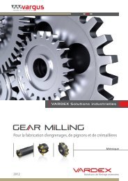
Advanced Technologies for Gear, Spline and Rack Manufacturing<br />
VARDEX presents an original and innovative solution for the gear milling industry, offering a competitive<br />
alternative to the traditional Hob system. Gear manufacturers can now mill external splines, external<br />
cylindrical gears, sprockets and racks as well as many additional gear applications with VARDEX gear<br />
milling tools.<br />
VARDEX GEAR MILLING Concept<br />
• Milling tools with multi-flute indexable carbide inserts.<br />
• Tailor-made inserts and holders designed per customer application. The inserts have the exact required profile<br />
shape (evolvent, involute or any other profile) which is transferred onto the component.<br />
1<br />
2<br />
Complete the slot in one pass.<br />
Rotate the component one pitch<br />
and machine another slot.<br />
Vardex System Advantages:<br />
• Super Fast - At least 50% less machining cycle compared to any other method:<br />
- Carbide inserts - High cutting speed<br />
- Full profile per pass - One pass per slot<br />
• Long Tool Life - Tough sub-micron substrate insert coating<br />
• Machining - Simple set-up and use on standard 3.5 axis CNC milling machine<br />
• Economical - Absolute Price/Performance advantage over existing technology<br />
• High Precision - Gears up to Class 7 according to DIN 3962 or Class 11 according to ANSI 390.03<br />
- Involute Splines according to DIN 5480 or ANSI B92.1<br />
- Straight sided Splines according to ISO 14-1982<br />
• Accuracy - No need for additional machining<br />
• Cutting Edges - Up to 3 cutting edges per insert for extended tool life<br />
• Quality - High surface finish<br />
2
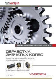
Major Applications<br />
GEAR<br />
The VARDEX Gear milling<br />
tools are suitable for<br />
machining both straight<br />
and helical teeth covering<br />
modules from 0.2-6.0mm<br />
or DP 128.0-4.0.<br />
SPLINE<br />
The VARDEX Spline<br />
milling tools are suitable<br />
for machining both<br />
involute or straightsided<br />
profiles, covering<br />
modules from 0.5-6.0mm<br />
or DP 48/96 - 4/8.<br />
RACK<br />
The VARDEX rack milling<br />
tools are suitable for<br />
covering modules<br />
from 0.2-6.0mm or<br />
DP 128.0-4.0.<br />
Gears, Splines and Racks can be machined with either Shell Mills, End Mills or Disc Mills.<br />
Shell Mill End Mill Disc Mill U Style<br />
3 Cutting Edges<br />
UT Style<br />
1 Cutting Edge<br />
3
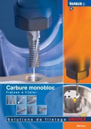
Gear Milling Insert<br />
Circular Pitch<br />
L2*<br />
L2*<br />
L<br />
L<br />
IC<br />
IC<br />
Module = Pitch / π<br />
U Style<br />
The VARDEX Concept<br />
The detailed table below describes the VARDEX gear milling machining concept.<br />
UT Style<br />
* L2 will be supplied with the inserts. Use the L2* for the machine set-up<br />
Tangent Length<br />
over (N) teeth<br />
According to the required customer application, VARDEX will design and supply unique inserts to suit a<br />
specific and single module / DP as well as the exact number of teeth used on the component.<br />
Root (Minor)<br />
Diameter<br />
Outside Diameter<br />
Example:<br />
For producing 2 gears with modules of 1.5 and 2, two separate IC 3/8” inserts are needed.<br />
Inserts for Gear, Spline and Rack<br />
All inserts are tailor-made according to the customer’s application<br />
Gear<br />
Range<br />
Spline<br />
Range<br />
Circular Pitch<br />
Rack<br />
Range<br />
Insert<br />
Toolholder<br />
Module<br />
Diametrical<br />
Pitch<br />
Module<br />
Diametrical<br />
Pitch<br />
Module<br />
Diametrical<br />
Pitch<br />
IC L inch Cutting<br />
Edge<br />
Required<br />
Tool<br />
See<br />
Pages<br />
0.2-1.0 26-128 0.5-1.25<br />
48/96;<br />
40/80;<br />
32/64;<br />
24/48<br />
0.2-1.0 26-128 1/4”U .43 3<br />
GME5S 100W125-197-2U 215/…<br />
GMD12S D335-100-2U 215/…<br />
5, 9<br />
1.0-1.5 17-26 1.5-2.0<br />
20/40;<br />
16/32<br />
1.0-1.5 17-26 3/8”U .63 3<br />
GME5S 125W142-315-3U 215/…<br />
GMS6S D165-050-3U 215/…<br />
GMS7S D189-075-3U 215/…<br />
GMD12S D354-100-3U 215/…<br />
5, 6, 9<br />
1.75-2.0 13-16 2.0-3.0<br />
3.0-3.5 8.5-9 4.0-5.0<br />
2.25-2.75 9.5-12 3.0-4.0<br />
3.5-6 4-7 5.0-6.0<br />
12/24;<br />
10/20;<br />
8/16<br />
6/12;<br />
5/10<br />
8/16;<br />
6/12<br />
5/10;<br />
4/8<br />
1.75-2.0 13-16 1/2”U .87 3 GMS7S D275-100-4U 215/… 7<br />
3.0-3.5 8.5-9 1/2”UT .87 1 GMS6S D335-100-4UT 215/… 7<br />
2.25-2.75 9.5-12 5/8”U 1.06 3 GMS6S D315-100-5U 215/… 8<br />
3.5-6 4-7 5/8”UT 1.06 1 GMS5S D315-100-5UT 215/… 8<br />
Ordering Code Example: 3UEM1.5GMVBX 210/...<br />
4
Toolholder - Weldon Shank for IC 1/4”U<br />
3 cutting edges<br />
D<br />
D2<br />
L2*<br />
L1<br />
D1<br />
L<br />
Image for * LP illustration will be supplied only, final with D2 the and inserts. D1 values Use will the be LP* supplied for the machine with the set-up toolholder<br />
For Gear, Rack and Spline<br />
Spare Parts (Ordering Code & EDP No.)<br />
Insert<br />
Size<br />
Cutting<br />
Edges<br />
Ordering Code<br />
Dimensions (mm)<br />
No. of<br />
Flutes<br />
IC L L1<br />
*L2<br />
(ref)<br />
D<br />
D1<br />
(max)<br />
D2<br />
(ref)<br />
Z Insert Screw Torx Key<br />
1/4”U 3 GME5S 100W125-197-2U 215/… 4.45 2.00 .19 1.00 1.22 1.25 5 SN2T (70036) HK2T (70227)<br />
* The L2 value is only for reference, for machine set-up use LP (see page 4).<br />
Toolholder - Weldon Shank for IC 3/8”U<br />
3 cutting edges<br />
D<br />
D2<br />
L2*<br />
L3≤L1<br />
D1<br />
L1<br />
L<br />
Image for illustration only, final D2 and D1 values will be supplied with the toolholder<br />
For Gear, Rack and Spline<br />
Spare Parts (Ordering Code & EDP No.)<br />
Insert<br />
Size<br />
Cutting<br />
Edges<br />
Ordering Code<br />
Dimensions (mm)<br />
No. of<br />
Flutes<br />
IC L L1<br />
*L2<br />
(ref)<br />
L3<br />
D<br />
D1<br />
(max)<br />
D2<br />
(ref)<br />
Z Insert Screw Torx+ Key<br />
3/8”U 3 GME5S 125W142-315-3U 215/… 5.90 3.14 .28 ≤3.14 1.25 1.38 1.42 5 SR3FIP8 (80973) KIP8 (70231)<br />
* The L2 value is only for reference, for machine set-up use LP (see page 4).<br />
Note: Customized toolholders are available upon request.<br />
5
Toolholder - Shell Mill for IC 3/8”U<br />
3 cutting edges<br />
D2<br />
d(H7) D1<br />
L2*<br />
H<br />
Image for illustration only, final D2 and D1 values will be supplied with the toolholder<br />
For Gear, Rack and Spline<br />
Spare Parts (Ordering Code & EDP No.)<br />
Insert<br />
Size<br />
Cutting<br />
Edges<br />
Ordering Code<br />
Dimensions (mm)<br />
No. of<br />
Flutes<br />
IC<br />
D1<br />
(max)<br />
D2<br />
(ref)<br />
d(H7)<br />
H<br />
*L2<br />
(ref)<br />
Z Insert Screw Torx+ Key Holder Screw<br />
3/8”U 3 GMS6S D165-050-3U 215/… 1.57 1.65 .50 1.60 .30 6 SR3FIP8 (80973) KIP8 (70231) 1/4-28x1.25 (70222)<br />
* The L2 value is only for reference, for machine set-up use LP (see page 4).<br />
Toolholder - Shell Mill for IC 3/8”U<br />
3 cutting edges<br />
D2<br />
d(H7) D1<br />
L2<br />
H<br />
Image for illustration only, final D2 and D1 values will be supplied with the toolholder<br />
For Gear, Rack and Spline<br />
Spare Parts (Ordering Code & EDP No.)<br />
Insert<br />
Size<br />
Cutting<br />
Edges<br />
Ordering Code<br />
Dimensions (mm)<br />
No. of<br />
Flutes<br />
IC<br />
D1<br />
(max)<br />
D2<br />
(ref)<br />
d(H7)<br />
H<br />
*L2<br />
(ref)<br />
Z Insert Screw Torx+ Key Holder Screw<br />
3/8”U 3 GMS7S D189-075-3U 215/… 1.77 1.89 .75 1.60 .30 7 SR3FIP8 (80973) KIP8 (70231) 3/8-24x1.25 (70223)<br />
* The L2 value is only for reference, for machine set-up use LP (see page 4).<br />
6<br />
Note: Customized toolholders are available upon request.
Toolholder – Shell Mill for IC 1/2”U<br />
3 cutting edges<br />
D2<br />
d(H7)<br />
D1<br />
L2*<br />
H<br />
Image for illustration only, final D2 and D1 values will be supplied with the toolholder<br />
For Gear, Rack and Spline<br />
Spare Parts (Ordering Code & EDP No.)<br />
Insert<br />
Size<br />
Cutting<br />
Edges<br />
Ordering Code<br />
Dimensions (mm)<br />
No. of<br />
Flutes<br />
IC<br />
D1<br />
(max)<br />
D2<br />
(ref)<br />
d(H7)<br />
H<br />
*L2<br />
(ref)<br />
Z Insert Screw Torx+ Key Holder Screw<br />
1/2”U 3 GMS7S D275-100-4U 215/… 2.67 2.75 1.00 1.97 .39 7 SR3FIP8 (80973) KIP8 (70231) 1/2-20x1.5 (70224)<br />
* The L2 value is only for reference, for machine set-up use LP (see page 4).<br />
Toolholder – Shell Mill for IC 1/2” UT<br />
1 cutting edge<br />
D2<br />
d(H7) D1<br />
L2*<br />
H<br />
Image for illustration only, final D2 and D1 values will be supplied with the toolholder<br />
For Gear, Rack and Spline<br />
Spare Parts (Ordering Code & EDP No.)<br />
Insert<br />
Size<br />
Cutting<br />
Edges<br />
Ordering Code<br />
Dimensions (mm)<br />
No. of<br />
Flutes<br />
IC<br />
D1<br />
(max)<br />
D2<br />
(ref)<br />
d(H7)<br />
H<br />
*L2<br />
(ref)<br />
Z Insert Screw Torx Key Holder Screw<br />
1/2”UT 1 GMS6S D335-100-4UT 215/… 3.27 3.35 1.00 1.97 .40 6 SN4T (70039) HK4T (70241) 1/2-20x1.5 (70224)<br />
* The L2 value is only for reference, for machine set-up use LP (see page 4).<br />
Note: Customized toolholders are available upon request.<br />
7
Toolholder - Shell Mill for IC 5/8”U<br />
3 cutting edges<br />
D2<br />
d(H7)<br />
D1<br />
L2*<br />
H<br />
Image for illustration only, final D2 and D1 values will be supplied with the toolholder<br />
For Gear, Rack and Spline<br />
Spare Parts (Ordering Code & EDP No.)<br />
Insert<br />
Size<br />
Cutting<br />
Edges<br />
Ordering Code<br />
Dimensions (mm)<br />
No. of<br />
Flutes<br />
IC<br />
D1<br />
(max)<br />
D2<br />
(ref)<br />
d(H7)<br />
H<br />
*L2<br />
(ref)<br />
Z Insert Screw Torx Key Holder Screw<br />
5/8”U 3 GMS6S D315-100-5U 215/… 3.07 3.15 1.00 1.97 .39 6 SN5TM (70041) HK5T (70229) 1/2-20x1.5 (70224)<br />
* The L2 value is only for reference, for machine set-up use LP (see page 4).<br />
Toolholder – Shell Mill for IC 5/8”UT<br />
1 cutting edge<br />
D2<br />
d(H7)<br />
D1<br />
L2*<br />
H<br />
Image for illustration only, final D2 and D1 values will be supplied with the toolholder<br />
For Gear, Rack and Spline<br />
Spare Parts (Ordering Code & EDP No.)<br />
Insert<br />
Size<br />
Cutting<br />
Edges<br />
Ordering Code<br />
Dimensions (mm)<br />
No. of<br />
Flutes<br />
IC<br />
D1<br />
(max)<br />
D2<br />
(ref)<br />
d(H7)<br />
H<br />
*L2<br />
(ref)<br />
Z Insert Screw Torx Key Holder Screw<br />
5/8”UT 1 GMS5S D315-100-5UT 215/… 3.07 3.15 1.00 1.97 .39 5 SN5TM (70041) HK5T (70229) 1/2-20x1.5 (70224)<br />
* The L2 value is only for reference, for machine set-up use LP (see page 4).<br />
8<br />
Note: Customized toolholders are available upon request.
Gear Milling Toolholder - Disk Mill for IC 1/4”U<br />
3 cutting edges<br />
L<br />
d(H6)<br />
D1<br />
L2*<br />
H<br />
D2<br />
Image for illustration only, final D2 and D1 values will be supplied with the toolholder<br />
For Gear, Rack and Spline<br />
Spare Parts (Ordering Code & EDP No.)<br />
Insert<br />
Size<br />
Cutting<br />
Edges<br />
Ordering Code<br />
Dimensions (mm)<br />
No. of<br />
Flutes<br />
IC<br />
D1<br />
(max)<br />
D2<br />
(ref)<br />
d(H6) H L<br />
*L2<br />
(ref)<br />
Z Insert Screw Torx Key<br />
1/4”U 3 GMD12S D335-100-2U 215/… 3.27 3.35 1.00 .49 1.0 .20 12 SN2T (70036) HK2T (70227)<br />
* The L2 value is only for reference, for machine set-up use LP (see page 4).<br />
Gear Milling Toolholder – Disc Mill for IC 3/8”U<br />
3 cutting edges<br />
L<br />
d(H6)<br />
D1<br />
L2*<br />
H<br />
D2<br />
Image for illustration only, final D2 and D1 values will be supplied with the toolholder<br />
For Gear, Rack and Spline<br />
Spare Parts (Ordering Code & EDP No.)<br />
Insert<br />
Size<br />
Cutting<br />
Edges<br />
Ordering Code<br />
Dimensions (mm)<br />
No. of<br />
Flutes<br />
IC<br />
D1<br />
(max)<br />
D2<br />
(ref)<br />
d(H6) H L<br />
*L2<br />
(ref)<br />
Z Insert Screw Torx+ Key<br />
3/8”U 3 GMD12S D354-100-3U 215/… 3.46 3.54 1.00 .49 1.0 .30 12 SR3FIP8 (80973) KIP8 (70231)<br />
* The L2 value is only for reference, for machine set-up use LP (see page 4).<br />
Note: Customized toolholders are available upon request.<br />
9
Recommended Grades, Cutting Speeds Vc [ft/min] and Feed f [<strong>Inch</strong>/tooth]<br />
Material<br />
Group<br />
P<br />
Steel<br />
M<br />
Stainless<br />
Steel<br />
K<br />
Cast Iron<br />
N(K)<br />
Non-Ferrous<br />
Metals<br />
S(M)<br />
Heat<br />
Resistant<br />
Material<br />
Vardex No.<br />
Hardness<br />
Brinell HB<br />
Vc [ft/min]<br />
Feed f<br />
[inch/tooth]<br />
Material<br />
VBX<br />
1<br />
Low carbon (C=0.1-0.25%) 125 328 - 689 .0079 - .0126<br />
2 Unalloyed steel<br />
Medium carbon (C=0.25-0.55%) 150 328 - 590 .0079 - .0126<br />
3 High Carbon (C=0.55-0.85%) 170 328 - 558 .0060 - .0090<br />
4<br />
Non hardened 180 197 - 295 .0067 - .011<br />
5<br />
Low alloy steel<br />
(alloying elements≤5%)<br />
Hardened 275 262 - 492 .0060 - .011<br />
6 Hardened 350 230 - 459 .0060 -.0098<br />
7 High alloy steel<br />
Annealed 200 197 - 426 .0060 - .0087<br />
8 (alloying elements>5%) Hardened 325 227 - 361 .0051 - .0083<br />
9<br />
Low alloy (alloying elements 5%) 225 230 - 394 .0047 - .0087<br />
11 Stainless steel<br />
Non hardened 200 328 - 558 .0060 - .0087<br />
12 Feritic<br />
Hardened 330 328 - 558 .0063 - .0091<br />
13 Stainless steel<br />
Austenitic 180 230 - 460 .0060 - .0098<br />
14 Austenitic<br />
Super Austenitic 200 230 - 460 .0047 - .0079<br />
15 Stainless steel<br />
Non hardened 200 230 - 460 .0063 - .0094<br />
16 Cast Feritic<br />
Hardened 330 230 - 460 .0047 - .0079<br />
17 Stainless steel<br />
Austenitic 200 230 - 394 .0060 - .0087<br />
18 Cast austenitic<br />
Hardened 330 230 - 394 .0047 - .0079<br />
28 Malleable<br />
Ferritic (short chips) 130 197 - 426 .0063 - .0095<br />
29 Cast iron<br />
Pearlitic (long chips) 230 197 - 394 .0060 - .0087<br />
30<br />
Low tensile strength 180 197 - 426 .0060 - .0087<br />
Grey cast iron<br />
31 High tensile strength 260 197 - 328 .0060 - .0087<br />
32<br />
Feritic 160 197 - 410 .0039 - .0079<br />
Nodular SG iron<br />
33 Pearlitic 260 164 - 295 .0060 - .0087<br />
34 Aluminium alloys<br />
Non aging 60 328 - 820 .0118 - .0197<br />
35 Wrought<br />
Aged 100 328 - 590 .011 - .0197<br />
36<br />
Cast 75 492 - 1312 .011 - .0197<br />
Aluminium alloys<br />
37 Cast & aged 90 492 - 918 .0098 - .0157<br />
38 Aluminium alloys Cast Si 13-22% 130 262 - 492 .011 - .0197<br />
39 Copper and<br />
Brass 90 394 - 689 .0118 - .0197<br />
40 Copper alloys<br />
Bronze and non leaded copper 100 394 - 689 .011 - .0197<br />
19<br />
Annealed (Iron based ) 200 66 - 148 .0035 - .0059<br />
20 High temperature Aged (Iron based) 280 66 - 98 .0028 - .0051<br />
21 alloys<br />
Annealed (Nickel or Cobalt based) 250 49 - 66 .0031 - .0059<br />
22 Aged (Nickel or Cobalt based) 350 33 - 49 .0031 - .0059<br />
23 Pure 99.5 Ti 400Rm 230 - 459 .0028 - .0051<br />
Titanium alloys<br />
24 α+β alloys 1050Rm 66 - 164 .0028 - .0051<br />
H(K)<br />
Hardened<br />
Material<br />
25<br />
45-50HRc 49 - 148 .002 - .0047<br />
Extra hard steel<br />
Hardened & tempered<br />
26 51-55HRc 49 - 131 .002 - .0047<br />
Grades<br />
U Style<br />
UT Style<br />
Grade<br />
VBX<br />
Application<br />
TiCN coated carbide grade.<br />
Excellent grade for general use.<br />
Other grades are available upon request.<br />
10
Price Quotation Form<br />
The VARDEX design is based on your application. Please complete the Required Dimensions below and<br />
together with the component drawing (if available) send to your local VARDEX distributor.<br />
Gear Dimensions<br />
M (Over Pins Diameter) / D (Over Balls Diameter)<br />
Pressure Angle<br />
Pin Diameter / Ball Diameter<br />
Outside Diameter<br />
Pitch Diameter<br />
Root (Minor)<br />
Diameter<br />
Fillet Radius<br />
Circular Pitch<br />
Tangent Length<br />
over (N) teeth<br />
Required Dimensions<br />
Dimensions<br />
Required Information<br />
1 Material to be Machined<br />
2 Number of Teeth<br />
3 Circular Pitch / Normal Module (mm)<br />
4 Pressure Angle<br />
5 Helix Angle<br />
6 Direction of Helix: RH/LH<br />
7 Outside Diameter ___ +/- ___<br />
8 Root (Minor) Diameter ___ +/- ___<br />
9 Fillet Radius<br />
10 Class of Accuracy (finishing only)<br />
11 Grinding Stock (roughing/semi finishing only)<br />
12 Teeth Measurement: Dimensions over two pins “M” or balls “D”<br />
Note: For Splines, lines 8, 9, 10 and 12 can be filled in with the Spline standard.<br />
11
For Gear, Spline & Rack Manufacturing<br />
<strong>Vargus</strong> USA<br />
1149 Barberry Drive<br />
Janesville, WI 53545 U.S.A<br />
Tel: +1-800-828-8765<br />
+1-608-756-4930<br />
Fax:+1-608-741-7125<br />
sales@vargususa.com<br />
www.vargususa.com<br />
221-01321<br />
I N C H E A<br />
0 1 / 2 0 1 2<br />
EDITION 01