- Page 1 and 2: MAN B&W S70MC-C8-TII Project Guide
- Page 3: MAN B&W Engine Design .............
- Page 6 and 7: MAN B&W Contents Chapter Section 5
- Page 8 and 9: MAN B&W Contents Chapter Section 14
- Page 11 and 12: MAN B&W Index Subject Section Subje
- Page 13 and 14: MAN B&W Index Subject Section Subje
- Page 15 and 16: MAN B&W Index Subject Section Subje
- Page 17: MAN B&W Index Subject Section Subje
- Page 21 and 22: MAN B&W 1.01 The MC/MC-C Tier II En
- Page 23 and 24: MAN B&W 1.02 Engine Type Designatio
- Page 25 and 26: MAN B&W 1.04 Engine Power Range and
- Page 27 and 28: MAN B&W 1.06 MC Engine Description
- Page 29 and 30: MAN B&W 1.06 Connecting Rod The con
- Page 31 and 32: MAN B&W 1.06 Fuel Oil Pump and Fuel
- Page 33 and 34: MAN B&W 1.06 All piping arrangement
- Page 35: MAN B&W Engine Layout and Load Diag
- Page 38 and 39: MAN B&W 2.01 placed on the light ru
- Page 40 and 41: MAN B&W 2.02 Constant ship speed li
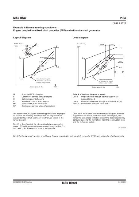
- Page 42 and 43: MAN B&W 2.04 Engine Layout and Load
- Page 44 and 45: MAN B&W 2.04 Line 4: Represents the
- Page 48 and 49: MAN B&W 2.04 Example 2: Special run
- Page 50 and 51: MAN B&W 2.04 Example 4: Special run
- Page 53 and 54: MAN B&W 2.05 Diagram for actual pro
- Page 55 and 56: MAN B&W 2.07 SFOC for High Efficien
- Page 57 and 58: MAN B&W 2.08 Examples of Graphic Ca
- Page 59 and 60: MAN B&W 2.09 SFOC for S70MC-C8 with
- Page 61 and 62: MAN B&W 2.10 Diagram b ����
- Page 63: MAN B&W 2.12 Emiss
- Page 67 and 68: MAN B&W 3.01 Turbocharger Selection
- Page 69 and 70: MAN B&W 3.02 Turbocharger MAN B&W S
- Page 71: MAN B&W 3.03 Air Orifice Air Proces
- Page 75 and 76: MAN B&W 4.01 Electricity Production
- Page 77 and 78: MAN B&W 4.01 Designation of PTO For
- Page 79 and 80: MAN B&W 4.01 The power from the cra
- Page 81 and 82: MAN B&W 4.02 � � � � � Th
- Page 83 and 84: MAN B&W 4.03 Pos. 1 Special face on
- Page 85 and 86: MAN B&W 4.03 DMG/CFE Generators Opt
- Page 87 and 88: MAN B&W 4.03 In such a case, the pr
- Page 89 and 90: MAN B&W 4.04 combinator mode. <stro
- Page 91 and 92: MAN B&W 4.05 Waste Heat Recovery Sy
- Page 93 and 94: MAN B&W 4.05 MAN B&W S70MC6, S70MC-
- Page 95 and 96: MAN B&W 4.05 �������
- Page 97 and 98:
MAN B&W 4.05 �������
- Page 99 and 100:
MAN Diesel 4.06 L16/24 GenSet Data
- Page 101 and 102:
MAN Diesel 4.06 L16/24 GenSet Data
- Page 103 and 104:
MAN Diesel 4.07 L21/31 GenSet Data
- Page 105 and 106:
MAN Diesel 4.08 L23/30H GenSet Data
- Page 107 and 108:
MAN Diesel 4.08 L23/30H GenSet Data
- Page 109 and 110:
MAN Diesel 4.09 L27/38 GenSet Data
- Page 111 and 112:
MAN Diesel 4.10 L28/32H GenSet Data
- Page 113:
MAN B&W MAN Diesel Installation Asp
- Page 116 and 117:
MAN B&W 5.02 Space Requirement �
- Page 118 and 119:
MAN B&W 5.03 Crane beam for overhau
- Page 120 and 121:
MAN B&W 5.03 Crane beam for overhau
- Page 122 and 123:
MAN B&W 5.04 Overhaul with MAN B&W
- Page 124 and 125:
MAN B&W 5.05 Engine Outline, Galler
- Page 126 and 127:
����� �� ����
- Page 128 and 129:
����� ������
- Page 130 and 131:
� ������� ���
- Page 132 and 133:
�� ����� � ��
- Page 134 and 135:
MAN B&W ������ ��
- Page 136 and 137:
MAN B&W 5.07 Centre of Gravity Fig.
- Page 139 and 140:
MAN B&W 5.09 Engine Pipe Connection
- Page 141 and 142:
� �� ���� ���
- Page 143 and 144:
� ��� ��� ���
- Page 145 and 146:
MAN B&W 5.09 Fig. 5.09.03a: Engine
- Page 147 and 148:
������ � � � �
- Page 149 and 150:
�� � �� �����
- Page 151 and 152:
MAN B&W 5.10 Counterflanges Page of
- Page 153 and 154:
MAN B&W 5.10 Counterflanges, Connec
- Page 155 and 156:
MAN B&W 5.10 MHI Type MET Fig. 5.10
- Page 157 and 158:
TCA MAN B&W 5.10 ABB Type TPL TPL T
- Page 159 and 160:
MAN B&W 5.11 Engine Seating and Hol
- Page 161 and 162:
MAN B&W 5.12 Engine Seating Profile
- Page 163 and 164:
MAN B&W 5.13 Engine Top Bracing The
- Page 165 and 166:
MAN B&W 5.14 Mechanical Top Bracing
- Page 167 and 168:
MAN B&W 5.15 Hydraulic Top Bracing
- Page 169 and 170:
MAN B&W 5.17 Shaftline Earthing Dev
- Page 171 and 172:
MAN B&W 5.17 When a generator <stro
- Page 173 and 174:
MAN B&W 5.18 Data Sheet for Propell
- Page 175 and 176:
MAN B&W 5.18 Servo oil system for V
- Page 177 and 178:
MAN B&W 5.18 Alphatronic 2000 Propu
- Page 179:
MAN B&W 5.18 Renk KAZ Clutch for au
- Page 183 and 184:
MAN B&W 6.01 Calculation of L<stron
- Page 185 and 186:
MAN B&W 6.03 List
- Page 187 and 188:
MAN B&W 6.03 List
- Page 189 and 190:
MAN B&W 6.04 Auxiliary Machinery Ca
- Page 191 and 192:
MAN B&W 6.04 Calculation of L<stron
- Page 193 and 194:
MAN B&W 6.04 Freshwater Generator I
- Page 195 and 196:
MAN B&W 6.04 Calculation of Freshwa
- Page 197 and 198:
MAN B&W 6.04 ∆m M% : change of sp
- Page 199 and 200:
MAN B&W 6.04 Calculation of Exhaust
- Page 201:
MAN B&W MAN Diesel Fuel 7
- Page 204 and 205:
MAN B&W 7.01 Fuel Oil System No val
- Page 206 and 207:
MAN B&W 7.02 Fuel Oils Marine diese
- Page 208 and 209:
MAN B&W 7.04 Fuel Oil Pipe Insulati
- Page 210 and 211:
MAN B&W 7.04 Fuel Oil Pipe Heat Tra
- Page 212 and 213:
MAN B&W 7.05 Fuel Oil Heater The he
- Page 214 and 215:
MAN B&W 7.06 Water In Fuel Emulsifi
- Page 217:
MAN B&W MAN Diesel Lubricating Oil
- Page 220 and 221:
MAN B&W 8.01 Lubricating and Coolin
- Page 222 and 223:
MAN B&W 8.03 Lubricating Oil Pipes
- Page 224 and 225:
MAN B&W 8.04 Lubricating Oil Centri
- Page 226 and 227:
MAN B&W 8.05 Lubricating oil full f
- Page 228 and 229:
MAN B&W 8.06 Lubricating Oil Tank
- Page 230 and 231:
MAN B&W 8.07 Crankcase Venting and
- Page 233 and 234:
MAN B&W 9.01 Cylinder Lubricating O
- Page 235 and 236:
MAN B&W 9.02 Alpha Adaptive Cylinde
- Page 237 and 238:
MAN B&W 9.02 Lubricator Control Sys
- Page 239 and 240:
MAN B&W 9.03 Mechanical Cylinder Lu
- Page 241:
MAN B&W MAN Diesel Pis</str
- Page 245:
MAN B&W MAN Diesel Central Cooling
- Page 248 and 249:
MAN B&W 11.02 Central Cooling Water
- Page 250 and 251:
MAN B&W 11.03 Jacket water system D
- Page 253 and 254:
MAN B&W 12.01 Seawater Systems The
- Page 255 and 256:
MAN B&W 12.03 Seawater Cooling Pipe
- Page 257 and 258:
MAN B&W 12.05 Jacket Cooling Water
- Page 259 and 260:
MAN B&W 12.07 Components for Jacket
- Page 261:
MAN B&W 12.08 Temperature at Start
- Page 265 and 266:
MAN B&W 13.01 Starting and Control
- Page 267 and 268:
MAN B&W 13.03 Starting and Control
- Page 269:
MAN B&W 13.04 Electric Motor for Tu
- Page 273 and 274:
MAN B&W 14.01 Scavenge Air System S
- Page 275 and 276:
MAN B&W 14.02 Control of the Auxili
- Page 277 and 278:
MAN B&W 14.03 Scavenge Air Pipes
- Page 279 and 280:
MAN B&W 14.05 Scavenge Air Cooler C
- Page 281 and 282:
MAN B&W 14.06 Scavenge Air Box Drai
- Page 283:
MAN B&W 14.07 Fire Extingui
- Page 287 and 288:
MAN B&W 15.01 Exhaust Gas System Th
- Page 289 and 290:
MAN B&W 15.02 Cleaning Systems AN P
- Page 291 and 292:
MAN B&W 15.03 Exhaust Gas System fo
- Page 293 and 294:
MAN B&W 15.04 Exhaust gas silencer
- Page 295 and 296:
MAN B&W 15.05 Measuring Back Pressu
- Page 297 and 298:
MAN B&W 15.06 Forces and Moments at
- Page 299:
MAN B&W 15.07 Diameter of Exhaust G
- Page 303 and 304:
MAN B&W 16.01 Engine Control System
- Page 305 and 306:
MAN B&W 16.01 Manoeuvring System on
- Page 307 and 308:
MAN B&W 16.01 Starting Air System E
- Page 309 and 310:
MAN B&W 16.01 Governor and Remote C
- Page 311 and 312:
MAN B&W 16.01 Engine Side Control C
- Page 313 and 314:
MAN B&W 16.01 Sequence diagram for
- Page 315 and 316:
MAN B&W 16.03 Engine Control System
- Page 317:
MAN B&W MAN Diesel Vibration Aspect
- Page 320 and 321:
MAN B&W 17.02 2nd Order Moments on
- Page 322 and 323:
MAN B&W 17.02 1st Order Moments on
- Page 324 and 325:
MAN B&W 17.03 Moment compensator Af
- Page 326 and 327:
MAN B&W 17.05 Guide Force Moments T
- Page 328 and 329:
MAN B&W 17.05 As the deflection sha
- Page 330 and 331:
MAN B&W 17.06 Critical Running When
- Page 333:
MAN B&W Monitoring Systems and Inst
- Page 336 and 337:
MAN B&W 18.02 PMI System As an opti
- Page 338 and 339:
MAN B&W 18.03 CoCoS-EDS The Compute
- Page 340 and 341:
MAN B&W 18.04 Alarm - Slow Down and
- Page 342 and 343:
MAN B&W 18.04 Alarms for UMS - Clas
- Page 344 and 345:
MAN B&W 18.04 Alarms for UMS - Clas
- Page 346 and 347:
MAN B&W 18.04 Shut down for AMS and
- Page 348 and 349:
MAN B&W 18.05 Local instruments Rem
- Page 350 and 351:
MAN B&W 18.06 Other Alarm Functions
- Page 352 and 353:
MAN B&W 18.06 Bearing Wear Monitori
- Page 354 and 355:
MAN B&W 18.06 Control Devices Senso
- Page 357:
MAN B&W Dispatch P
- Page 360 and 361:
MAN B&W 19.01 MAN Diesel’s recomm
- Page 362 and 363:
MAN B&W 19.03 Disp
- Page 364 and 365:
MAN B&W 19.03 A4 + B4 (option 4 12
- Page 366 and 367:
MAN B&W 19.05 Shop Test Minimum del
- Page 368 and 369:
MAN B&W 19.07 Additional Spares Pag
- Page 370 and 371:
MAN B&W 19.07 Overflow valve, <stro
- Page 372 and 373:
MAN B&W 19.08 The wearing parts are
- Page 374 and 375:
MAN B&W 19.08 Table B Group No. Ser
- Page 376 and 377:
MAN B&W 19.08 Table B Group No. Ser
- Page 378 and 379:
MAN B&W 19.10 List
- Page 380 and 381:
MAN B&W 19.10 1 2 � � � � P
- Page 382 and 383:
MAN B&W 19.10 1 � � Fig. 19.10.
- Page 384 and 385:
MAN B&W 19.10 1 � Pos. Descriptio
- Page 386 and 387:
MAN B&W 19.10 1 � �����
- Page 388 and 389:
MAN B&W 19.10 1 � Pos. Descriptio
- Page 390 and 391:
MAN B&W 19.11 Tool Panels Pos. Sect
- Page 393 and 394:
MAN B&W 20.01 Project Support and D
- Page 395 and 396:
MAN B&W 20.03 Extent of Delivery Th
- Page 397 and 398:
MAN B&W 20.04 Installation Document
- Page 399 and 400:
MAN B&W 20.04 Main Section 917 Engi
- Page 401:
MAN B&W MAN Diesel Appendix A
- Page 404 and 405:
MAN B&W Appendix A No. Symbol Symbo


