Contents Norgren Pneumatic Actuator Products
Contents Norgren Pneumatic Actuator Products
Contents Norgren Pneumatic Actuator Products

You also want an ePaper? Increase the reach of your titles
YUMPU automatically turns print PDFs into web optimized ePapers that Google loves.
APC-103<br />
11/02<br />
Supersedes 12/01<br />
<strong>Norgren</strong> <strong>Pneumatic</strong><br />
<strong>Actuator</strong> <strong>Products</strong><br />
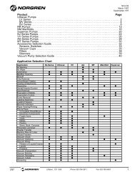
<strong>Contents</strong><br />
<strong>Pneumatic</strong> <strong>Actuator</strong> <strong>Products</strong> Overview . . . . . . . . . . . . . . .ACT-2<br />
NFPA Aluminum & Steel <strong>Actuator</strong>s . . . . . . . . . . . . . . . . .ACT-1-1<br />
Series SS Stainless Steel <strong>Actuator</strong>s . . . . . . . . . . . . . . . . .ACT-2-1<br />
Series N Non-Rotating <strong>Actuator</strong>s . . . . . . . . . . . . . . . . . . .ACT-3-1<br />
Series 8000 & 8000/M ISO/VDMA <strong>Actuator</strong>s . . . . . . . . . . .ACT-4-1<br />
Tiny Tim <strong>Actuator</strong>s . . . . . . . . . . . . . . . . . . . . . . . . . . . . . .ACT-5-1<br />
Roundline Stainless Steel <strong>Actuator</strong>s . . . . . . . . . . . . . . . .ACT-6-1<br />
Miniature Roundline Cylinders . . . . . . . . . . . . . . . . . . . . .ACT-7-1<br />
Series 90000 Compact <strong>Actuator</strong>s . . . . . . . . . . . . . . . . . . .ACT-8-1<br />
Compact Interchangeable <strong>Actuator</strong>s . . . . . . . . . . . . . . . .ACT-9-1<br />
Lintra Series 46000 Rodless <strong>Actuator</strong>s . . . . . . . . . . . . .ACT-10-1<br />
Lintra-Lite Series A44000 Rodless <strong>Actuator</strong>s . . . . . . . .ACT-11-1<br />
Rack & Pinion Rotary <strong>Actuator</strong>s . . . . . . . . . . . . . . . . . . .ACT-12-1<br />
Miniature Rotary <strong>Actuator</strong>s . . . . . . . . . . . . . . . . . . . . . . .ACT-13-1<br />
Vane Rotary <strong>Actuator</strong>s . . . . . . . . . . . . . . . . . . . . . . . . . .ACT-14-1<br />
<strong>Pneumatic</strong> Grippers . . . . . . . . . . . . . . . . . . . . . . . . . . . .ACT-15-1<br />
Fittings, Accessories, and Helpful<br />
Engineering Information . . . . . . . . . . . . . . . . . . . . . .ACT-16-1<br />
Brookville, OH USA Phone 937-833-4033 www.norgren.com ACT-1
<strong>Norgren</strong> <strong>Actuator</strong> <strong>Products</strong><br />
<strong>Norgren</strong> <strong>Pneumatic</strong> <strong>Actuator</strong>s<br />
Section 1 – NFPA Aluminum & Steel <strong>Actuator</strong>s<br />
Fluids: Filtered compressed air to 250 psi (17 bar)<br />
Operating Pressure: 250 psi (17 bar)<br />
Operating Temperature:<br />
Series EA -20˚F to 200˚F (-29˚C to 107˚C)<br />
with Viton Seals -20˚F to 400˚F (-29˚C to 204˚C)<br />
Bore Sizes: 1-1/2", 2", 2-1/2", 3-1/4", 4", 5", 6", 7", 8", 10”, 12”<br />
Section 2 – Series SS Stainless Steel <strong>Actuator</strong>s<br />
Fluids: Filtered compressed air to 250 PSI<br />
Petroleum based hydraulic fluid to 400 PSI<br />
Lubrication: None required<br />
Operating Pressure:<br />
250 psig air(17.2 bar)<br />
400 psig hydraulic (27.6 bar)<br />
Operating Temperatures:<br />
Series SS: -40° to 200°F (-40° to 93°C)<br />
Series D: -20° to 250°F (-29° to 204°C)<br />
with Viton Seals: -20° to 400°F (-29° to 204°C)<br />
Bore Sizes: 1.125" (29mm), 1.50" (38mm), 2.0" (51mm), 2.50" (64mm), 3.25"<br />
(83mm), 4.0" (102mm), 5.0" (127mm), 6.0" (152mm), 8.0" (203mm)<br />
Section 3– Series N Non-Rotating <strong>Actuator</strong>s<br />
Fluids: Filtered compressed air to 250 psi<br />
(For hydraulic service consult factory.)<br />
Operating Pressure: 250 psig (17.2 bar)<br />
Operating Temperatures: -20° to 200°F (-29° to 93°C)<br />
Bore Sizes: 1.125" (29mm), 1.50" (38mm), 2.0" (51mm), 2.50" (64mm),<br />
3.25" (83mm), 4.0" (102mm)<br />
Section 4 – 8000 & 8000/M ISO VDMA <strong>Actuator</strong>s<br />
Fluids: Compressed air, filtered, lubricated and non-lubricated<br />
Operating Pressure: 1 to 16 bar (14.5 to 232 psig)<br />
Operating Temperature: -20° to 80°C max (-4° to 176°F max)<br />
(Consult Technical Services for use below 2°C (35°F)<br />
Bore Sizes: 32, 40, 50, 63, 80, 100, 125, 160, 200, 250, 320 mm<br />
Note: Corrosion Resistant available.<br />
Section 5 – Tiny Tim <strong>Actuator</strong>s<br />
Fluids: Filtered compressed air to 150 psi (10 bar)<br />
Operating Pressure: 150 psi (10 bar)<br />
Operating Temperature:<br />
-20° to 225°F (-30° to 110°C) with Standard Seals<br />
-40° to 200°F (-40° to 90°C) with Buna N Seals<br />
-40° to 350°F (-40° to 175°C) with Viton Seals<br />
Bore Sizes: 3/4", 1", 1-1/8"<br />
ACT-2 Brookville, OH USA Phone 937-833-4033 www.norgren.com
<strong>Norgren</strong> <strong>Actuator</strong> <strong>Products</strong><br />
<strong>Norgren</strong> <strong>Pneumatic</strong> <strong>Actuator</strong>s<br />
Section 6 – Roundline Stainless Steel Body <strong>Actuator</strong>s<br />
Fluids: Filtered, lubricated or non-lubricated, compressed air<br />
Maximum Operating Pressure: 250 psig (17.2 bar)<br />
Temperature Range:<br />
Standard Nitrile Seals: -20° to 200°F (-29° to 93°C)<br />
Viton Seals: -20° to 400°F (-29° to 205°C)<br />
Bore Sizes: .438" (11mm), .563" (14mm), .75" (19mm), 1.063" (27mm),<br />
1.25" (32mm), 1.50" (40mm), 2.0" (50mm), 2.50" (63)<br />
Section 7– Mini Roundline <strong>Pneumatic</strong> Cyinder<br />
Fluids: Compressed air filtered, lubricated or non-lubricated<br />
Operating Pressure: 50.75 to 101.5 psig (3.5 to 7 bar)<br />
Operating Temperature: 32°F to 140°F (0°C to 60°C)<br />
Bore Sizes: ø 2.5 mm & 4 mm<br />
Section 8 – Series 90000 Compact <strong>Actuator</strong>s<br />
Fluids: Compressed air, filtered, lubricated or non-lubricated<br />
Operating Pressure: 14.5 to 145 PSI (1 to 10 bar)<br />
Operating Temperature: 23°* to 176°F (-5°* to 80 °C)<br />
* Consult Technical Service for use below 35°F (2° C)<br />
Bore Sizes: 0.50"(12mm), 0.625" (16mm), 0.75" (20mm), 1.0" (25mm),<br />
1.25" (32mm), 1.50" (40mm), 2.0" (50mm) 2.50" (63mm),<br />
3.125" (80mm), 4.0" (100mm)<br />
Section 9 – Compact Interchangeable <strong>Pneumatic</strong> <strong>Actuator</strong><br />
Fluids: Compressed air filtered, lubricated or non-lubricated<br />
Operating Pressure: 14.5 to 145 psig (1 to 10 bar)<br />
Operating Temperature: -25°F to 250°F (-32°C to 121°C)<br />
Bore Sizes: 0.5" (12mm), 0.63" (16mm), 0.79 (20mm), 0.98 (25mm), 1.26"<br />
(32mm), 1.57" (40mm), 1.97" (50mm), 2.48” (63mm), 3.15”<br />
(80mm), 3.94” (100mm), 4.92” (125mm), 5.51” (140mm),<br />
6.3” (160mm).<br />
Section 10 – Lintra Series 46000 Rodless <strong>Actuator</strong>s<br />
Fluids: Compressed air filtered to 50µ and lubricated<br />
Operating Pressure<br />
16 mm: 22 to 150 psig (1.5 to 10 bar)<br />
20 mm to 80 mm: 15 to 150 psig (1 to 10 bar)<br />
Operating Temperatures<br />
-22° to 180°F* (-30°C to 80°C)<br />
*With dewpoint of supply air less than ambient air temperature.<br />
Bore Sizes: 0.63" (16mm), 0.79 (20mm), 0.98 (25mm), 1.26" (32mm),<br />
1.57" (40mm), 1.97" (50mm),2.48" (63mm), 3.15" (80mm)<br />
Brookville, OH USA Phone 937-833-4033 www.norgren.com ACT-3
<strong>Norgren</strong> <strong>Actuator</strong> <strong>Products</strong><br />
<strong>Norgren</strong> <strong>Pneumatic</strong> <strong>Actuator</strong>s<br />
Section 11 – Lintra-Lite Series A440000 Rodless <strong>Actuator</strong>s<br />
Fluids: Compressed air, filtered to 50µ and lubricated<br />
Operating Pressure: 15 to 118 psig ( 1 to 8 bar)<br />
Operating Temperatures: -22° to 180°F* (-30° to 80°C)<br />
*With dewpoint of supply air less than ambient air temperature at cylinder,<br />
consult our Technical Service for use below 36°F (2°C)<br />
Bore Sizes: 1.0" (25mm), 1.25" (32mm), 1.50" (40mm)<br />
Section 12 – Rack and Pinion Rotary <strong>Actuator</strong>s<br />
Fluids: Filtered compressed air to 150 psi (10 bar)<br />
Operating Pressure: 150 psi (10 bar)<br />
Operating Temperature:<br />
-20° to 200°F (-29° to 93°C) with Standard Nitrile Seals<br />
-20° to 400°F (-29° to 204°C) with Viton® Seals<br />
-20° to 250°F (-29° to 121°C) with Low Friction Seals<br />
Bore Sizes: 0.50" (12mm), 0.75" (20mm), 1.125" (29mm), 1.50" (38mm), 2.00"<br />
(50mm), 2.50" (64mm)<br />
Section 13 – Mini <strong>Pneumatic</strong> Rotary <strong>Actuator</strong>s<br />
Fluids: Compressed air filtered, lubricated or non-lubricated<br />
Operating Pressure: 14.5 to 101.5 psig ( 1 to 7 bar)<br />
Operating Temperatures: 32°F to 140°F* (5°C to 60°C)<br />
*With dewpoint of supply air less than ambient air temperature at cylinder,<br />
consult our Technical Service for use below 36°F (2°C)<br />
Size Range: ø 0.47" to 0.87" (12 mm to 22 mm)<br />
Section 14 – Rotary Vane <strong>Actuator</strong>s<br />
Fluids: Lubricated or non-lubricated, filtered, compressed air<br />
Operating Pressure:<br />
M/60280, M/60281: 44 to 102 psig (3 to 7 bar)<br />
M/60282, C/60283: 29 to 102 psig (2 to 7 bar)<br />
C/60284, C/60084/TI: 29 to 145 psig (2 to 10 bar)<br />
Operating Temperature: 40° to 140°F (5° to 60°C)<br />
Section 15 – <strong>Pneumatic</strong> Grippers<br />
Fluids: Compressed air filtered, lubricated or non-lubricated<br />
Operating Pressure<br />
29 to 101.5 psig (2 to 7 bar) - See individual components for pressures<br />
Operating Temperatures<br />
32°F to 140°F* (0°C to 60°C)<br />
*With dewpoint of supply air less than ambient air temperature.<br />
ACT-4 Brookville, OH USA Phone 937-833-4033 www.norgren.com
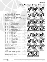
Section 1<br />
NFPA Aluminum & Steel Cylinders<br />
Page ACT-1-18<br />
Cylinder with<br />
01 (MS4)<br />
Side Tapped<br />
Page ACT-1-22<br />
Cylinder with<br />
03 (MF1) Head<br />
Rectangular Flange<br />
Page ACT-1-24<br />
Cylinder with<br />
03 (ME3) Head<br />
Square Flange<br />
Series “A” Aluminum (1-1/2" to 8") &<br />
Series “J” Steel (1-1/2"to 12") Bore Cylinder Features<br />
Series “A” and “J” Technical Features . . . . . . . . . . . . . . . . ACT-1-2, ACT-1-6<br />
Series “EA” Aluminum (1-1/2" to 8") &<br />
Series “EJ” Steel (1-1/2"to 12") Bore Cylinder Features<br />
Series “EA” and “EJ” Impact Dampening Seals . . . . ACT-1-4, ACT-1-8, ACT-1-12<br />
Series “EA” and “EJ” Technical Features . . . . . . . . . . . . . . ACT-1-5, ACT-1-9<br />
Decel Cushioned Cylinder . . . . . . . . . . . . . . . . . . . . . . . . . . . . . . . . ACT-1-10<br />
General Technical Information . . . . . . . . . . . . . . . . . . . . . . . . . . . . . ACT-1-13<br />
Page ACT-1-24<br />
Cylinder with<br />
04 (ME4) Cap<br />
Square Flange<br />
Page ACT-1-26<br />
Cylinder with<br />
04 (MF2) Cap<br />
Rectangular Flange<br />
Page ACT-1-28<br />
Cylinder with<br />
05 (MX0) Basic<br />
Code NFPA Bore Sizes Description<br />
01 MS4 1-1/2" – 12" Side Tapped . . . . . . . . . . . . . . . . . . . . . ACT-1-18<br />
03 MF1 1-1/2" – 6" Head Rectangular Flange . . . . . . . . . . . . ACT-1-22<br />
03 ME3 7" – 12" Head Square Flange . . . . . . . . . . . . . . . . ACT-1-24<br />
04 ME4 7" – 12" Cap Square Flange . . . . . . . . . . . . . . . . ACT-1-24<br />
04 MF2 1-1/2" – 6" Cap Rectangular Flange . . . . . . . . . . . . . ACT-1-26<br />
05 MX0 1-1/2" – 12" Basic . . . . . . . . . . . . . . . . . . . . . . . . . . . ACT-1-28<br />
06 MX1 1-1/2" – 12" 4 Tie Rods Both Ends . . . . . . . . . . . . . . ACT-1-32<br />
6C MX2 1-1/2" – 12" Cap Tie Rods . . . . . . . . . . . . . . . . . . . . . ACT-1-32<br />
6R MX3 1-1/2" – 12" Head Tie Rods . . . . . . . . . . . . . . . . . . . . ACT-1-32<br />
6B MX4 1-1/2" – 12" 2 Tie Rods Both Ends . . . . . . . . . . . . . . ACT-1-32<br />
7R MT1 1-1/2" – 8" Removable Head Trunnion (A & EA Only) . . . . ACT-1-36<br />
07 MT1 1-1/2" – 12 Head Trunnion (J & EJ Only) . . . . . . . . . . . ACT-1-36<br />
8R MT2 1-1/2" – 8" Removable Cap Trunnion . . . . . . . . . . . . ACT-1-40<br />
08 MT2 1-1/2" – 12 Cap Trunnion . . . . . . . . . . . . . . . . . . . . . ACT-1-40<br />
09 MS2 1-1/2" – 12" Side Lugs . . . . . . . . . . . . . . . . . . . . . . . ACT-1-44<br />
10 MT4 1-1/2" – 12" Intermediate Center Trunnion . . . . . . . . . ACT-1-48<br />
11 MS1 1-1/2" – 12" Side End Angles . . . . . . . . . . . . . . . . . . . ACT-1-52<br />
12 MP1 1-1/2" – 12" Cap Fixed Clevis . . . . . . . . . . . . . . . . . . ACT-1-56<br />
15 MS7 1-1/2" – 8" Side End Lugs . . . . . . . . . . . . . . . . . . . . ACT-1-60<br />
16 N/A 1-1/2" – 6" Sleeve Nut Construction Universal . . . . . . ACT-1-62<br />
20 MF5 1-1/2" – 6" Head Square Flange . . . . . . . . . . . . . . . . ACT-1-64<br />
21 MF6 1-1/2" – 6" Cap Square Flange . . . . . . . . . . . . . . . . ACT-1-66<br />
22 MP2 1-1/2" – 8" Detachable Cap Clevis . . . . . . . . . . . . . . ACT-1-68<br />
32 MP3 1-1/2" – 12" Cap Fixed Eye . . . . . . . . . . . . . . . . . . . . ACT-1-70<br />
42 MP4 1-1/2" – 8" Detachable Cap Eye . . . . . . . . . . . . . . . . ACT-1-74<br />
52 N/A 1-1/2" – 8" Spherical Bearing . . . . . . . . . . . . . . . . . . ACT-1-76<br />
60 N/A 1-1/2" – 6" Base Bar (A & EA) . . . . . . . . . . . . . . . . . ACT-1-78<br />
Series DA & EDA (Aluminum) and<br />
DJ & EDJ (Steel) Double Rod End Cylinders . . . . . . . . . . . . . . . . . . . ACT-1-80<br />
Series A & EA (1-1/2" to 8") and<br />
Series J & EJ (1-1/2" to12") Cylinder Accessories . . . . . . . . . . . . . . . ACT-1-84<br />
Series A & EA and J & EJ Optional Features & Custom Cylinders . . . . ACT-1-86<br />
Stroke Signal Valve/Pneulectric Valve . . . . . . . . . . . . . . . . . . . . . . . . . ACT-1-88<br />
Reed & Solid State Switch Information . . . . . . . . . . . . . . . . . . . . . . . . ACT-1-90<br />
Flow Controls . . . . . . . . . . . . . . . . . . . . . . . . . . . . . . . . . . . . . . . . . . ACT-1-92<br />
Rod Alignment Coupler . . . . . . . . . . . . . . . . . . . . . . . . . . . . . . . . . . . ACT-1-94<br />
Air-Oil Tank . . . . . . . . . . . . . . . . . . . . . . . . . . . . . . . . . . . . . . . . . . . ACT-1-94<br />
Series A & EA and J & EJ Standard and Special Options . . . . . . . . . . ACT-1-95<br />
Series A & EA (1-1/2" - 8") and Series J & EJ (1-1/2" - 12")<br />
Order Information . . . . . . . . . . . . . . . . . . . . . . . . . . . . . . . . . . . . . . ACT-1-96<br />
Seal Replacement Kits for Series A, EA, J & EJ . . . . . . . . . . . . . . . . . ACT-1-97<br />
Page ACT-1-32<br />
Cylinder with<br />
06 (MX1) Tie Rod-4,<br />
6C (MX2) Cap, 6R (MX3)<br />
Head, 6B (MX4) Tie Rod-2<br />
Page ACT-1-44<br />
Cylinder with<br />
09 (MS2)<br />
Side Lugs<br />
Page ACT-1-56<br />
Cylinder with<br />
12 (MP1) Cap<br />
Fixed Clevis<br />
Page ACT-1-64<br />
Cylinder with<br />
20 (MF5) Head<br />
Square Flange<br />
Page ACT-1-70<br />
Cylinder with<br />
32 (MP3) Cap<br />
Fixed Eye<br />
Page ACT-1-36<br />
Cylinder with<br />
07 (MT1)<br />
Head Trunnion<br />
Page ACT-1-48<br />
Cylinder with<br />
10 (MT4) Intermediate<br />
Center Trunnion<br />
Page ACT-1-60<br />
Cylinder with<br />
15 (MS7)<br />
Side End Lugs<br />
Page ACT-1-66<br />
Cylinder with<br />
21 (MF6) Cap<br />
Square Flange<br />
Page ACT-1-74<br />
Cylinder with<br />
42 (MP4) Detachable<br />
Cap Eye<br />
Page ACT-1-40<br />
Cylinder with<br />
08 (MT2)<br />
Cap Trunnion<br />
Page ACT-1-52<br />
Cylinder with<br />
11 (MS1)<br />
Side End Angles<br />
Page ACT-1-62<br />
Cylinder with 16<br />
Sleeve Nut Construction<br />
Side Tapped (Universal)<br />
Page ACT-1-68<br />
Cylinder with<br />
22 (MP2) Detachable<br />
Clevis<br />
Page ACT-1-76<br />
Cylinder with<br />
52 Spherical Bearing<br />
NFPA - National Fluid Power Association<br />
Page ACT-1-78<br />
Cylinder with 60 Base Bar<br />
(A & EA Only)<br />
Page ACT-1-80<br />
Double Rod End Cylinders<br />
Brookville, OH USA Phone 937-833-4033 www.norgren.com ACT-1-1
Series A, NFPA Aluminum Air Cylinders (ø1-1/2" to 8"), Cylinder Features<br />
Series A Cylinders are constructed with the finest materials for each component!<br />
1 Piston Rod: Hard chrome plated<br />
high-tensile steel, ground and polished.<br />
2 Rod Bearing: External removable<br />
threaded steel bearing housing (black<br />
oxide finish), with an oil-impregnated<br />
sintered iron rod bearing.<br />
3 Rod Seal: Nitrile lip-type seal<br />
is pressure energized and wear<br />
compensating for durability and long life.<br />
4 Head/Cap: Precision machined from<br />
alloy aluminum, then anodized for<br />
corrosion resistance (black finish).<br />
1<br />
2<br />
5<br />
4<br />
3 6<br />
5 Ultra Cushion ® Seals: Advanced<br />
design features a unique, one-piece,<br />
compound seal of nitrile* captured within<br />
a precision machined groove. Linear and<br />
radial “float” of the cushion seals<br />
eliminates misalignment. Ultra Cushions<br />
provide exceptionally fast “out of<br />
cushion” stroke reversal. (Head and Cap<br />
Cushions are optional.)<br />
*Nitrile seals on the 5/8" & 1" rod diameter.<br />
For rod sizes 1-3/8" and larger, urethane seals are standard.<br />
6 O-Ring Tube Seal: Buna is<br />
standard. (Viton is optional.)<br />
7<br />
7 Tie Rods: High-strength steel maintains<br />
uniform compression on tube end seals.<br />
8 Piston: Machined solid aluminum<br />
alloy, light-weight for low inertia, yet<br />
strong. Threaded piston is installed with<br />
high strength threadlocker adhesive then<br />
staked to the piston rod.<br />
9 Adjustable Captive Cushion<br />
Needle: A one-piece, precision threaded<br />
brass cushion adjustment screw with a<br />
threaded steel capture ring. It provides<br />
safe and precise cushion adjustment.<br />
8<br />
6<br />
9<br />
10<br />
11<br />
12<br />
13<br />
12<br />
4<br />
10 Wiper Seal: Lip-type urethane<br />
wiper seal keeps contaminates<br />
from getting into cylinder by<br />
aggressively wiping foreign materials<br />
from the piston rod, enhancing the<br />
rod seal life.<br />
Application Information<br />
Series A NFPA interchangeable aluminum air<br />
cylinders are offered with a variety of accessories,<br />
standard and optional equipment to meet your<br />
application needs.<br />
9<br />
11 Cylinder Tube: High-strength<br />
aluminum alloy ideally suited for air<br />
service. The tube is clear anodized on the<br />
O.D. and hard anodic coated on the I.D.,<br />
resulting in a smooth, file hard (60RC),<br />
corrosion and score resistant<br />
surface finish.<br />
The addition of a Teflon ® wear ring to the<br />
outer perimeter of the piston permits us to<br />
guarantee its operation against failure due<br />
to lack of lubrication for ONE FULL YEAR,<br />
regardless of cycles! See page ACT-1-98 for<br />
complete warranty.<br />
12 Piston Seals: Long-wearing<br />
nitrile seals.<br />
13 Wear Ring: Reinforced Teflon ®<br />
compounded with polyphenylene sulfide<br />
provides supreme wear and excellent<br />
bearing support.<br />
Standard non-cushioned Series A cylinders are<br />
recommended for applications that require full<br />
bottoming of the piston and where the noise<br />
emitted by the metal-to-metal impact between the<br />
piston and cylinder end caps is tolerable. We<br />
recommend that optional non-adjustable cushions<br />
be added for piston speeds (moving light tools)<br />
ranging from 15 to 30 in/sec. For speeds exceeding<br />
30 in/sec, the cylinders should be equipped with<br />
adjustable air cushions.<br />
ACT-1-2 Brookville, OH USA Phone 937-833-4033 www.norgren.com
Series EA, NFPA Aluminum Air Cylinders (ø1-1/2" to 8"), Cylinder Features<br />
Series EA Ecology Cylinders are constructed with the finest<br />
materials for each component!<br />
1 Ultra Cushion ® Seals: Advanced<br />
design features a unique, one-piece,<br />
compound seal of nitrile* captured within<br />
a precision machined groove. Linear and<br />
radial “float” of the cushion seals<br />
eliminates misalignment. Ultra Cushions<br />
provide exceptionally fast “out of cushion”<br />
stroke reversal. (Head and Cap Cushions<br />
are optional.)<br />
*Nitrile seals on the 5/8" & 1" rod diameter.<br />
For rod sizes 1-3/8" and larger, urethane seals are standard.<br />
1<br />
2 2<br />
3<br />
2 Impact Dampening Piston Seals:<br />
Our impact dampening piston seals, in<br />
conjunction with our advanced cushion<br />
design, decelerate and reduce<br />
end-of-stroke noise.<br />
3 Piston: Machined solid aluminum<br />
alloy, light-weight for low inertia, yet<br />
strong. Threaded piston is installed with<br />
high strength threadlocker adhesive then<br />
staked to the piston rod.<br />
4 O-Ring Tube Seal: Buna is standard.<br />
(Viton is optional.)<br />
5 Adjustable Captive Cushion Needle<br />
(not shown): Fine thread allows<br />
for safe and precision adjustment of<br />
cushion. (See page 2.)<br />
6 Wiper Seal: Lip-type urethane wiper<br />
seal keeps contaminates from getting<br />
into cylinder by aggressively wiping<br />
foreign materials from the piston rod,<br />
enhancing the rod seal life.<br />
7 Piston Rod: Hard chrome plated<br />
high-tensile steel, ground and polished.<br />
4<br />
6<br />
7<br />
8<br />
4<br />
9<br />
10<br />
11<br />
12<br />
8 Head/Cap: Precision machined from<br />
alloy aluminum, then anodized for<br />
corrosion resistance (black finish).<br />
9 Wear Ring: Reinforced Teflon ®<br />
compounded with polyphenylene sulfide<br />
provides supreme wear and excellent<br />
bearing support.<br />
10 Tie Rods: High-strength steel<br />
maintains uniform compression on<br />
tube end seals.<br />
11 Cylinder Tube: High-strength<br />
aluminum alloy ideally suited for air<br />
service. The tube is clear anodized on the<br />
O.D. and hard anodic coated on the I.D.,<br />
resulting in a smooth, file hard (60RC),<br />
corrosion and score resistant surface<br />
finish.<br />
1<br />
8<br />
13<br />
12 Rod Seal: Nitrile lip-type seal is<br />
pressure energized and wear<br />
compensating for durability<br />
and long life.<br />
13 Rod Bearing: External removable<br />
steel bearing housing (black oxide<br />
finish), with an oil-impregnated<br />
sintered iron rod bearing.<br />
Brookville, OH USA Phone 937-833-4033 www.norgren.com ACT-1-3
Series A & EA, NFPA Aluminum Air Cylinders, Impact Dampening Seals<br />
<strong>Norgren</strong> Ecology Cylinders offer these advantages:<br />
1 2<br />
<strong>Norgren</strong> Guarantees<br />
Non-lubricated Operation<br />
for a Full Year!<br />
The piston rod is self-lubricated by the<br />
oil-impregnated rod bearing during operation.<br />
Lubrication between piston and cylinder barrel<br />
is derived from the polishing qualities of the<br />
reinforced Teflon ® wear ring.<br />
The low friction surfaces extend the life of the<br />
seals beyond normal expectations, permitting<br />
<strong>Norgren</strong> to unconditionally guarantee nonlubricated<br />
operation for one full year. See page ACT-1-98 for<br />
complete warranty.<br />
Series EA cylinders are NFPA interchangeable<br />
and are available in many different mounting styles.<br />
Operates Quietly<br />
to Meet<br />
OSHA Specifications.<br />
Series EA cylinders provide substantial reductions<br />
in impact noise, which reduces overall machine<br />
noise and helps meet government regulations.<br />
Summary of Sound Levels in Decibels<br />
Cylinder Model<br />
PSI Air Sound<br />
Pressure A133B3 EA155B3 A1133A3 EA1155A3<br />
Level+ 5" x 6" 5" x 6" 2" x 6" 2" x 6"<br />
95 End++ 108 73 110 74<br />
PSI+ Side++ 112 84 110 81<br />
50 End++ 108 73 113 74<br />
PSI+ Side++ 113 85 110 81<br />
The summary of sound decibels chart illustrates the<br />
operating sound levels.<br />
The impact dampening qualities of the<br />
Piston Seals are guaranteed for ONE FULL YEAR!<br />
+ Peak sound pressure is given in decibels (dB)<br />
re:2 x 10 5 N/m 2 .<br />
++End position of mike was 3' on centerline from end of<br />
cylinder; side position of mike was 3' perpendicular to<br />
centerline abeam of end of cylinder.<br />
Note: At 5 feet, cylinder sound levels would be less by 9 dB<br />
from side figure and 13 dB from end figure. The total noise<br />
emitted will depend on the structure to which the cylinder is<br />
attached. If it is mounted on a thin flat plate of considerable<br />
area, the noise will be increased by a sounding board effect.<br />
3Energy Absorption<br />
Capacity of the Impact<br />
Dampening Seals<br />
The impact-dampening<br />
Piston Seals in the Series EA cylinder<br />
allow for guaranteed, repeatable cushioning.<br />
The compressive qualities of the piston seals are<br />
predictable. The degree of seal compression at<br />
various supply pressures is documented. (See<br />
Energy Absorption Chart.) This allows you to<br />
compute the exact cylinder size required by<br />
knowing the weight (pounds) you are stopping<br />
at a given speed.<br />
Series EA cylinders have a impact dampening<br />
piston seal that accomplishes 80% of the actual<br />
load stopping. The air cushion accounts for only<br />
20%. (A conventional air cushioning cylinder<br />
depends 100% on the compressibility of air to do<br />
the stopping.) The EA seal absorbs high impact<br />
loads allowing the effect of the air cushion to be<br />
reduced by using a larger air cushion bleed<br />
orifice. As a result the piston can move at a faster<br />
speed for a longer period of time before the EA<br />
seal does the final stopping.<br />
See illustration at top of ACT-1-5 for cushion<br />
operation.<br />
Energy Absorption Capacity of the Impact Dampening Seals<br />
*Usable Pounds Stoppable at the Following Piston Speeds<br />
This chart features the energy absorption capacity of the impact dampening piston seals<br />
with Non-Adjustable cushions. For higher loads and velocities please refer to the Decel-Air Cushion<br />
Option on ACT-1-10.<br />
In/Sec<br />
Cylinder Bore<br />
1 1 /2 2 2 1 /2 3 1 /4 4 5 6 7 8<br />
6 155.6 275.5 499.8 969.3 1505.4 2603.2 4159.8 5794.2 8067.6<br />
12 38.4 68.1 123.4 239.7 372.6 644.8 1030.2 1435.8 2000.4<br />
18 16.7 29.7 53.7 104.6 162.8 282.1 450.6 628.7 876.8<br />
24 9.2 16.3 29.4 57.3 89.4 155.2 247.8 346.2 483.6<br />
30 5.6 10.0 18.1 35.4 55.4 96.4 153.9 215.4 301.6<br />
36 3.7 6.7 11.9 23.5 37.0 64.5 102.9 144.4 202.7<br />
42 2.6 4.6 8.2 16.3 25.8 45.3 72.2 101.6 143.1<br />
48 1.8 3.2 5.8 11.7 18.6 32.8 52.2 73.8 104.4<br />
54 1.3 2.4 4.2 8.5 13.6 24.2 38.5 54.7 77.9<br />
60 1.0 1.8 3.0 6.2 10.1 18.1 28.7 41.1 58.9<br />
*The weight of the cylinder piston has been deducted from the figures shown above.<br />
Note: The use of Viton ® Seals limits the absorption of the impact dampening seals by 50%.<br />
Energy absorption capacity of the impact dampening<br />
piston seals with an adjustable cushion.<br />
In/Sec<br />
Cylinder Bore<br />
1 1 /2 2 2 1 /2 3 1 /4 4 5 6 7 8<br />
6 279 495 899 1,744 2,709 4,685 7,486 10,429 4,520<br />
12 68 122 221 430 699 1,159 1,854 2,583 3,800<br />
18 30 53 95 187 291 507 810 1,130 1,576<br />
24 16 29 52 102 160 279 444 622 869<br />
30 10 18 32 63 99 172 275 387 541<br />
36 6.7 12 21.6 42 66 116 183 259 363<br />
42 4.7 8.3 14.7 29 46 81 129 181 257<br />
48 3.4 5.7 10.4 21 33 59 93 131 187<br />
54 2.3 4.3 7.6 15.3 24 43 68 97 138<br />
60 1.8 3.2 5.4 11 18 33 52 74 106<br />
Effect of Impact Dampening Seals on Total Stroke of Cylinders<br />
PSI<br />
Cylinder Bore<br />
1 1 /2 2 2 1 /2 3 1 /4 4 5 6 7 8<br />
0 .14 .15 .17 .19 .22 .25 .28 .32 .32<br />
20 .10 .10 .12 .14 .16 .18 .20 .22 .22<br />
40 .07 .07 .08 .09 .10 .12 .13 .14 .14<br />
60 .04 .04 .05 .05 .06 .07 .07 .08 .08<br />
80 .02 .02 .02 .02 .03 .03 .03 .04 .04<br />
100 0 0 0 0 0 0 0 0 0<br />
Note: These figures are for new cylinders. The impact dampening seals will take some compression set during operation<br />
of the cylinder and the stroke loss will decrease. Also, the pressure at zero stroke loss will decrease to about 80 psi.<br />
At pressures above those of zero stroke loss, a slight clicking sound may be produced during impact.<br />
To determine the stroke loss for either the head or cap end, divide the value shown by 2.<br />
ACT-1-4 Brookville, OH USA Phone 937-833-4033 www.norgren.com
Cushion Function<br />
Series A & EA, NFPA Aluminum Air Cylinders (ø1-1/2" to 8"), Technical Features<br />
As the cushion spear enters the cushion cavity, the<br />
exhaust port becomes sealed off creating an air brake. This<br />
provides the initial deceleration in piston speed. The<br />
oversized air cushion bleed orifice permits the cushion<br />
pressure to exhaust with minimal restriction. This allows<br />
the piston to move quickly and smoothly through the<br />
cushion length.<br />
Operating Temperatures:<br />
Series EA -20˚F to 200˚F<br />
(-29˚C to 107˚C)<br />
with Viton Seals -20˚F to 400˚F<br />
(-29˚C to 204˚C)<br />
Operating Pressure:<br />
250 PSIG Air (17 Bar)<br />
EA Cylinders cannot be used<br />
in hydraulic applications.<br />
Bore Sizes: 1-1/2", 2", 2-1/2", 3-1/4",<br />
4", 5", 6", 7", 8"<br />
Supply:<br />
Filtered compressed air to 250 PSI<br />
Air Cylinder Selection:<br />
The proper application and selection of an air<br />
cylinder requires full consideration of the<br />
following: the fluid medium, operating<br />
pressures, mounting style, length of stroke,<br />
type of rod connection to the load, thrust or<br />
mounting tension on the rod, mounting<br />
attitude, speed of the stroke and how the load<br />
motion will be stopped.<br />
The data that follows provides the necessary<br />
information in the evaluation of<br />
As the piston continues its travel to the point of impact<br />
with the end caps, the compressive qualities of the EJ seal<br />
provide the final decelerating force. This action compresses<br />
the EJ seal and absorbs the remaining kinetic shock<br />
vibration and noise created by the impact.<br />
Lubrication:<br />
None required<br />
<strong>Norgren</strong> Air Cylinders are rated for “no lube<br />
added” service. All internal components are<br />
lubricated at time of assembly with a Teflon ®<br />
based grease.<br />
Materials:<br />
Head and End Caps: black anodized<br />
6061-T6 aluminum<br />
Tube: 6063-T832 aluminum, clear<br />
anodized O.D., hardcoat anodized I.D.<br />
Rod: hard chrome plated steel<br />
Piston: machined high-strength<br />
aluminum alloy<br />
Rod Bearing: oil impregnated sintered iron<br />
Seals: nitrile rod seal, urethane rod wiper,<br />
nitrile piston seals, nitrile tube end seals<br />
Tie Rods: high-tensile strength steel<br />
an average application and will help you in<br />
selecting the proper cylinder model and size<br />
for your particular application.<br />
Note: 1-1/2", 2", 2-1/2", 3-1/4", 4" and 5" bore<br />
cylinders with 1/2" to 2" strokes will be<br />
furnished with a short head cushion sleeve<br />
and short cap cushion spear.<br />
Only available on 5/8" and 1" rods.<br />
The above specification applies to Series EA<br />
cylinders with standard non-adjustable or<br />
optional adjustable cushions.<br />
On the reverse stroke the EJ seal releases its compressive<br />
energy to propel the piston away from the end caps,<br />
producing an immediate breakaway.<br />
Side Loading:<br />
Cylinders are specifically designed to push and<br />
pull. Side loading(misalignment)<br />
of the piston rod should be avoided to ensure<br />
maximum operating performance and life.<br />
Care should be taken during installation<br />
to properly align the load to be moved with the<br />
center line of the cylinder.<br />
The use of a rod alignment coupler (see<br />
page ACT-1-94) is strongly recommended<br />
whenever possible.<br />
Series EA Fixed Cushions<br />
Piston and rod assembly<br />
for 1-1/2" thru 5"<br />
bore cylinders with<br />
less than 1/2" stroke,<br />
and 6" thru 8"<br />
bore cylinders<br />
with less than 2" stroke.<br />
Piston and rod<br />
assembly for<br />
1-1/2" thru 5"<br />
bore cylinders<br />
with 1/2" to 2" stroke.<br />
Ultra Cushion ®<br />
<strong>Norgren</strong>’s advanced cushion design features a unique, onepiece,<br />
nitrile compound seal that is captured within a<br />
precision machined groove. This allows both linear<br />
and radial “float” of the cushion seal which<br />
virtually eliminates problems associated<br />
with misalignment. Integral flow paths<br />
molded in the periphery of the seal provide<br />
exceptionally fast “out of cushion” stroke<br />
Figure 1 Figure 2 shows spear<br />
reversal without the use of ball checks.<br />
exiting cushion seal.<br />
A Major Design and Performance Breakthrough in Air Cylinder Cushioning Systems!<br />
Brookville, OH USA Phone 937-833-4033 www.norgren.com ACT-1-5
Series J, NFPA Steel Air Cylinders (ø1-1/2" to 12"), Cylinder Features<br />
Series J Cylinders are constructed with the finest materials for each component!<br />
1 Piston Rod: Hard chrome plated<br />
high-tensile steel, ground and polished.<br />
2 Rod Bearing: External removable<br />
threaded steel bearing housing (black<br />
oxide finish), with an oil-impregnated<br />
sintered iron rod bearing.<br />
3 Rod Seal: Nitrile lip-type seal<br />
is pressure energized and wear<br />
compensating for durability and long life.<br />
4 Head/Cap: Precision machined from<br />
steel, then black oxide finished 1-1/2" to<br />
2-1/2" bores. Painted black finish on<br />
3-1/4" to 12" bores.<br />
1<br />
5<br />
4<br />
3 6<br />
5 Ultra Cushion ® Seals: Advanced<br />
design features a unique, one-piece,<br />
compound seal of nitrile* captured within<br />
a precision machined groove. Linear and<br />
radial “float” of the cushion seals<br />
eliminates misalignment. Ultra Cushions<br />
provide exceptionally fast “out of<br />
cushion” stroke reversal. (Head and Cap<br />
Cushions are optional.)<br />
*Nitrile seals on the 5/8" & 1" rod diameter.<br />
For rod sizes 1-3/8" and larger, urethane seals are standard.<br />
6 O-Ring Tube Seal: Buna is<br />
standard. (Viton is optional.)<br />
7<br />
8<br />
7 Tie Rods: High-strength steel<br />
maintains uniform compression on<br />
tube end seals.<br />
8 Piston: Machined solid steel,<br />
for high strength. Threaded piston is<br />
installed with high strength threadlocker<br />
adhesive then staked to the piston rod.<br />
9 Adjustable Captive Cushion<br />
Needle: A one-piece, precision threaded<br />
brass cushion adjustment screw with a<br />
threaded steel capture ring. It provides<br />
safe and precise cushion adjustment.<br />
6<br />
9<br />
2<br />
10<br />
11<br />
12<br />
13<br />
12<br />
4<br />
10 Wiper Seal: Lip-type urethane<br />
wiper seal keeps contaminates<br />
from getting into cylinder by<br />
aggressively wiping foreign materials<br />
from the piston rod, enhancing the<br />
rod seal life.<br />
9<br />
11 Cylinder Tube: High-strength<br />
aluminum alloy 1-1/2", 2", 2-1/2" bore<br />
anodized on the O.D. and hard coat I.D.<br />
Steel cylinder tube hard chrome plated<br />
I.D. 3-1/4" to 12" bore.<br />
12 Piston Seals: Long-wearing<br />
nitrile seals.<br />
13 Wear Ring: Reinforced Teflon ®<br />
compounded with polyphenylene sulfide<br />
provides supreme wear and excellent<br />
bearing support.<br />
Application Information<br />
Series J NFPA interchangeable steel air cylinders<br />
are offered with a variety of accessories, standard<br />
and optional equipment to meet your application<br />
needs.<br />
The addition of a Teflon ® wear ring to the outer<br />
perimeter of the piston permits us to guarantee its<br />
operation against failure due to lack of lubrication<br />
for ONE FULL YEAR, regardless of cycles! See page<br />
ACT-1-98 for complete warranty.<br />
Standard non-cushioned Series J cylinders are<br />
recommended for applications that require full<br />
bottoming of the piston and where the noise emitted<br />
by the metal-to-metal impact between the piston and<br />
cylinder end caps is tolerable. We recommend that<br />
optional non-adjustable cushions be added for<br />
piston speeds (moving light tools) ranging from 15<br />
to 30 in/sec. For speeds exceeding 30 in/sec, the<br />
cylinders should be equipped with adjustable air<br />
cushions.<br />
ACT-1-6 Brookville, OH USA Phone 937-833-4033 www.norgren.com
Series J, NFPA Steel Air Cylinders (ø1-1/2" to 12"), Cylinder Features<br />
Series EJ Ecology Cylinders are constructed with the finest<br />
materials for each component!<br />
1 Ultra Cushion ® Seals: Advanced<br />
design features a unique, one-piece,<br />
compound seal of nitrile* captured<br />
within a precision machined groove.<br />
Linear and radial “float” of the cushion<br />
seals eliminates misalignment. Ultra<br />
Cushions provide exceptionally fast “out<br />
of cushion” stroke reversal. (Head and<br />
Cap Cushions are optional.)<br />
*Nitrile seals on the 5/8" & 1" rod diameter.<br />
For rod sizes 1-3/8" and larger, urethane seals are standard.<br />
1<br />
2<br />
2<br />
3<br />
2 Impact Dampening Piston Seals:<br />
Our impact dampening piston seals, in<br />
conjunction with our advanced cushion<br />
design, decelerate and reduce<br />
end-of-stroke noise.<br />
3 Piston: Machined solid steel, for high<br />
strength. Threaded piston is installed with<br />
high strength threadlocker adhesive then<br />
staked to the piston rod.<br />
4 O-Ring Tube Seal: Buna is standard.<br />
(Viton is optional.)<br />
5 Adjustable Captive Cushion Needle<br />
(not shown): Fine thread allows<br />
for safe and precision adjustment of<br />
cushion. (See page ACT-1-6.)<br />
6 Wiper Seal: Lip-type urethane wiper<br />
seal keeps contaminates from getting<br />
into cylinder by aggressively wiping<br />
foreign materials from the piston rod,<br />
enhancing the rod seal life.<br />
4<br />
6<br />
7<br />
8<br />
4<br />
9<br />
10<br />
11<br />
12<br />
7 Piston Rod: Hard chrome plated<br />
high-tensile steel, ground and polished.<br />
1<br />
8<br />
13<br />
8 Head/Cap: Precision machined from<br />
steel, then black oxide finished 1-1/2" to<br />
2-1/2" bores. Painted black finish 3-1/4"<br />
to 12" bores.<br />
9 Wear Ring: Reinforced Teflon ®<br />
compounded with polyphenylene sulfide<br />
provides supreme wear and excellent<br />
bearing support.<br />
10 Tie Rods: High-strength steel<br />
maintains uniform compression on<br />
tube end seals.<br />
11 Cylinder Tube: High-strength<br />
aluminum alloy 1-1/2", 2". 2-1/2" bore<br />
anodized on the O.D. and hard coat I.D.<br />
Steel cylinder tube hard chrome plated<br />
I.D. 3-1/4" to 12" bore.<br />
12 Rod Seal: Nitrile lip-type seal is<br />
pressure energized and wear<br />
compensating for durability and long life.<br />
Rod Bearing: External removable<br />
13 steel bearing housing (black oxide<br />
finish), with an oil-impregnated sintered<br />
iron rod bearing.<br />
Brookville, OH USA Phone 937-833-4033 www.norgren.com ACT-1-7
Series J & EJ, NFPA Steel Air Cylinders, Impact Dampening Seals<br />
<strong>Norgren</strong> Ecology Cylinders offer these advantages:<br />
1 2<br />
<strong>Norgren</strong> Guarantees<br />
Non-lubricated Operation<br />
for a Full Year!<br />
The piston rod is self-lubricated by the<br />
oil-impregnated rod bearing during operation.<br />
Lubrication between piston and cylinder barrel<br />
is derived from the polishing qualities of the<br />
reinforced Teflon ® wear ring.<br />
The low friction surfaces extend the life of the<br />
seals beyond normal expectations, permitting<br />
<strong>Norgren</strong> to unconditionally guarantee nonlubricated<br />
operation for one full year.<br />
See page ACT-1-98 for complete warranty.<br />
Series EJ cylinders are NFPA interchangeable<br />
and are available in many different mounting styles.<br />
3Energy Absorption<br />
Capacity of the Impact<br />
Dampening Seals<br />
The impact-dampening<br />
Piston Seals in the Series EJ cylinder<br />
allow for guaranteed, repeatable cushioning.<br />
The compressive qualities of the piston seals are<br />
predictable. The degree of seal compression at<br />
various supply pressures is documented. (See<br />
Energy Absorption Chart.) This allows you to<br />
compute the exact cylinder size required by<br />
knowing the weight (pounds) you are stopping<br />
at a given speed.<br />
Series EJ cylinders have a impact dampening<br />
piston seal that accomplishes 80% of the actual<br />
load stopping. The air cushion accounts for only<br />
20%. (A conventional air cushioning cylinder<br />
depends 100% on the compressibility<br />
of air to do the stopping.) The EJ seal absorbs<br />
high impact loads allowing the effect of the air<br />
cushion<br />
to be reduced by using a larger air cushion bleed<br />
orifice. As a result the piston can move at a faster<br />
speed for a longer period of time before the EJ<br />
seal does the final stopping. See illustration at top<br />
of ACT-1-9 for cushion operation.<br />
Operates Quietly<br />
to Meet<br />
OSHA Specifications.<br />
Series EJ cylinders provide substantial reductions in<br />
impact noise, which reduces overall machine noise<br />
and helps meet government regulations.<br />
Summary of Sound Levels in Decibels<br />
PSI Air Sound<br />
Cylinder Model<br />
Pressure J133B3 EJ155B3 J1133A3 EJ1155A3<br />
Level+ 5" x 6" 5" x 6" 2" x 6" 2" x 6"<br />
95 End++ 108 73 110 74<br />
PSI+ Side++ 112 84 110 81<br />
50 End++ 108 73 113 74<br />
PSI+ Side++ 113 85 110 81<br />
The summary of sound decibels chart illustrates the<br />
operating sound levels.<br />
The impact dampening qualities of the<br />
Piston Seals are guaranteed for ONE FULL YEAR!<br />
+ Peak sound pressure is given in decibels (dB)<br />
re:2 x 10 5 N/m 2 .<br />
++End position of mike was 3' on centerline from end of<br />
cylinder; side position of mike was 3' perpendicular to<br />
centerline abeam of end of cylinder.<br />
Note: At 5 feet, cylinder sound levels would be less by 9 dB<br />
from side figure and 13 dB from end figure. The total noise<br />
emitted will depend on the structure to which the cylinder is<br />
attached. If it is mounted on a thin flat plate of considerable<br />
area, the noise will be increased by a sounding board effect.<br />
Energy Absorption Capacity of the Impact Dampening Seals<br />
*Usable Pounds Stoppable at the Following Piston Speeds<br />
This chart features the energy absorption capacity of the impact dampening piston seals<br />
with a Non-Adjustable cushions. For higher loads and velocities please refer to the Decel- Air<br />
Cushion option on ACT-1-10.<br />
In/Sec<br />
Cylinder Bore<br />
1 1 /2 2 2 1 /2 3 1 /4 4 5 6 7 8 10 12<br />
6 155.6 275.5 499.8 969.3 1505.4 2603.2 4159.8 5794.2 8067.6 12,242 20,139<br />
12 38.4 68.1 123.4 239.7 372.6 644.8 1030.2 1435.8 2000.4 3026 4971<br />
18 16.7 29.7 53.7 104.6 162.8 282.1 450.6 628.7 876.8 1319.3 2162.1<br />
24 9.2 16.3 29.4 57.3 89.4 155.2 247.8 346.2 483.6 722 1179<br />
30 5.6 10.0 18.1 35.4 55.4 96.4 153.9 215.4 301.6 445.5 724<br />
36 3.7 6.7 11.9 23.5 37.0 64.5 102.9 144.4 202.7 295.3 476.8<br />
42 2.6 4.6 8.2 16.3 25.8 45.3 72.2 101.6 143.1 204.8 327.7<br />
48 1.8 3.2 5.8 11.7 18.6 32.8 52.2 73.8 104.4 146 231<br />
54 1.3 2.4 4.2 8.5 13.6 24.2 38.5 54.7 77.9 105.7 164.7<br />
60 1.0 1.8 3.0 6.2 10.1 18.1 28.7 41.1 58.9 76.9 117.2<br />
*The weight of the cylinder piston has been deducted from the figures shown above.<br />
Note: The use of Viton ® Seals limits the absorption of the impact dampening seals by 50%.<br />
Energy absorption capacity of the impact dampening<br />
piston seals with an adjustable cushion.<br />
In/Sec<br />
Cylinder Bore<br />
1 1 /2 2 2 1 /2 3 1 /4 4 5 6 7 8 10 12<br />
6 279 495 899 1,744 2,709 4,685 7,486 10,429 4,520 22,035 36,250<br />
12 68 122 221 430 699 1,159 1,854 2,583 3,800 5,446 8,947<br />
18 30 53 95 187 291 507 810 1,130 1,576 2,374 3,891<br />
24 16 29 52 102 160 279 444 622 869 1,299 1,414<br />
30 10 18 32 63 99 172 275 387 541 801 1,303<br />
36 6.7 12 21.6 42 66 116 183 259 363 531 856<br />
42 4.7 8.3 14.7 29 46 81 129 181 257 367 588<br />
48 3.4 5.7 10.4 21 33 59 93 131 187 262 415<br />
54 2.3 4.3 7.6 15.3 24 43 68 97 138 189 295<br />
60 1.8 3.2 5.4 11 18 33 52 74 106 138 211<br />
Effect of Impact Dampening Seals on Total Stroke of Cylinders<br />
PSI<br />
Cylinder Bore<br />
1 1 /2 2 2 1 /2 3 1 /4 4 5 6 7 8 10 12<br />
0 .14 .15 .17 .19 .22 .25 .28 .32 .32 .36 .40<br />
20 .10 .10 .12 .14 .16 .18 .20 .22 .22 .24 .26<br />
40 .07 .07 .08 .09 .10 .12 .13 .14 .14 .15 .16<br />
60 .04 .04 .05 .05 .06 .07 .07 .08 .08 .09 .10<br />
80 .02 .02 .02 .02 .03 .03 .03 .04 .04 .04 .04<br />
100 0 0 0 0 0 0 0 0 0 0 0<br />
Note: These figures are for new cylinders. The impact dampening seals will take some compression set during operation<br />
of the cylinder and the stroke loss will decrease. Also, the pressure at zero stroke loss will decrease to about 80 psi.<br />
At pressures above those of zero stroke loss, a slight clicking sound may be produced during impact.<br />
To determine the stroke loss for either the head or cap end, divide the value shown by 2.<br />
ACT-1-8 Brookville, OH USA Phone 937-833-4033 www.norgren.com
Cushion Function<br />
Series J & EJ, NFPA Steel Air Cylinders (ø1-1/2" to 12"), Technical Features<br />
As the cushion spear enters the cushion cavity, the<br />
exhaust port becomes sealed off creating an air brake. This<br />
provides the initial deceleration in piston speed. The<br />
oversized air cushion bleed orifice permits the cushion<br />
pressure to exhaust with minimal restriction. This allows<br />
the piston to move quickly and smoothly through the<br />
cushion length.<br />
As the piston continues its travel to the point of impact<br />
with the end caps, the compressive qualities of the EJ seal<br />
provide the final decelerating force. This action compresses<br />
the EJ seal and absorbs the remaining kinetic shock<br />
vibration and noise created by the impact.<br />
On the reverse stroke the EJ seal releases its compressive<br />
energy to propel the piston away from the end caps,<br />
producing an immediate breakaway.<br />
Operating Temperatures:<br />
Series J -20°F to 200°F<br />
(-29°C to 107°C)<br />
with Viton Seals -20˚F to 400˚F<br />
(-29˚C to 204˚C)<br />
Operating Pressure:<br />
250 PSIG Air (17.2 Bar)<br />
400 PSIG Hydraulic (27.6 Bar)<br />
Bore Sizes: 1-1/2", 2", 2-1/2", 3-1/4",<br />
4", 5", 6", 7", 8", 10", 12"<br />
Supply:<br />
Filtered compressed air to 250 PSI Petroleum<br />
based hydraulic fluid to 400 PSI<br />
Air Cylinder Selection:<br />
The proper application and selection of an air<br />
cylinder requires full consideration of the<br />
following: the fluid medium, operating<br />
pressures, mounting style, length of stroke,<br />
type of rod connection to the load, thrust or<br />
mounting tension on the rod, mounting<br />
attitude, speed of the stroke and how the load<br />
motion will be stopped.<br />
The data that follows provides the necessary<br />
information in the evaluation of<br />
Lubrication:<br />
None required<br />
<strong>Norgren</strong> Air Cylinders are rated for “no lube<br />
added” service. All internal components are<br />
lubricated at time of assembly with a Teflon ®<br />
based grease.<br />
Materials:<br />
Head and End Caps: precision<br />
machined steel<br />
Tube: 6063-T832 aluminum, clear<br />
anodized O.D., hard coat anodized I.D.<br />
Rod: hard chrome plated steel<br />
Piston: machined high-strength<br />
aluminum alloy<br />
Rod Bearing: oil impregnated sintered iron<br />
Seals: nitrile rod seal, urethane rod wiper,<br />
nitrile piston seals, nitrile tube<br />
end seals<br />
Tie Rods: high-tensile strength steel<br />
an average application and will help you in<br />
selecting the proper cylinder model and size<br />
for your particular application.<br />
Note: 1-1/2", 2", 2-1/2", 3-1/4", 4" and 5" bore<br />
cylinders with 1/2" to 2" strokes will be<br />
furnished with a short head cushion sleeve<br />
and short cap cushion spear.<br />
Only available on 5/8" and 1" rods.<br />
The above specification applies to Series J<br />
cylinders with optional non-adjustable or<br />
adjustable cushions.<br />
Side Loading:<br />
Cylinders are specifically designed to push and<br />
pull. Side loading (misalignment)<br />
of the piston rod should be avoided to ensure<br />
maximum operating performance and life.<br />
Care should be taken during installation<br />
to properly align the load to be moved with the<br />
center line of the cylinder.<br />
The use of a rod alignment coupler (see page<br />
ACT-1-94 is strongly recommended whenever<br />
possible.<br />
Series J Fixed Cushions<br />
Piston and rod<br />
assembly for<br />
1-1/2" thru 5"<br />
bore cylinders<br />
with 1/2" to 2" stroke.<br />
Ultra Cushion ®<br />
<strong>Norgren</strong>’s advanced cushion design features a unique, onepiece,<br />
nitrile compound seal that is captured within a<br />
precision machined groove. This allows both linear<br />
and radial “float” of the cushion seal which<br />
virtually eliminates problems associated<br />
with misalignment. Integral flow paths<br />
molded in the periphery of the seal provide<br />
exceptionally fast “out of cushion” stroke<br />
Figure 1 Figure 2 shows spear<br />
reversal without the use of ball checks.<br />
exiting cushion seal.<br />
A Major Design and Performance Breakthrough in Air Cylinder Cushioning Systems!<br />
Brookville, OH USA Phone 937-833-4033 www.norgren.com ACT-1-9
Series A & EA, NFPA Aluminum Decel-Air Cushioned Cylinder<br />
Series J & EJ, NFPA Steel Decel-Air Cushioned Cylinder<br />
Decel-Air Cushioned Cylinder<br />
Eliminates the need for shock absorbers on air cylinder applications.<br />
Decel-Air Cushion Spacer<br />
Block allows for extra<br />
cushion length and longer<br />
deceleration<br />
Impact Dampening<br />
“Ecology” Piston Seals<br />
absorb final impact and<br />
provide end of stroke<br />
cushioning assistance.<br />
Adjustable Captive<br />
Cushion Needle is a<br />
one-piece, precision<br />
threaded brass cushion<br />
adjustment screw with a<br />
threaded steel capture<br />
ring. It provides safe and<br />
precise cushion<br />
adjustment<br />
Extra cushion sleeve and<br />
stud length for longer<br />
deceleration<br />
Ultra Cushion Seals are made of nitrile*<br />
captured within a precision machined groove.<br />
The seal’s linear and radial “float” eliminates<br />
misalignment and provides exceptionally fast<br />
“out of cushion” stroke reversal.<br />
*Nitrile seals on the 5/8" and 1" rod diameter. For rod<br />
sizes 1-3/8" and larger urethane seals are standard.<br />
Explanation of Decel-Air Cushion:<br />
<strong>Norgren</strong>’s Decel Cushioned cylinder was designed for<br />
applications where high velocity, low mass, material transfer or<br />
machine function is required, and where the kinetic energy to<br />
be absorbed during cushioning exceeds the parameters of our<br />
standard Series EA or EJ air cylinders equipped with nonadjustable<br />
or adjustable cushions. Decel cushions employ<br />
longer-than-standard air cushions to assist our Impact<br />
Dampening Piston Seal.<br />
Why does our Decel-Air Cushion work?<br />
The extra cushion length of the Decel cushioned cylinder<br />
provides an additional deceleration capability to slow the<br />
cylinder’s moving mass to a point where the positive<br />
cushioning effect of our Impact Dampening Piston Seals can<br />
perform the final cushioning.<br />
<strong>Norgren</strong>’s Decel-Air Cushioned Cylinders<br />
Versus<br />
Cylinder Mounted Shock Absorbers<br />
The first extensive evaluation of pneumatic cylinder cushion<br />
performance was undertaken by the Mechanical Engineering<br />
Department of The Ohio State University. The test was<br />
conducted on 2-1/2” bore, 12” stroke.<br />
The OSU tests found the Decel Cushioned cylinders absorbed<br />
almost three times as much kinetic energy with a lower level of<br />
peak cushion as a standard Ecology seal configured cylinder.<br />
Because air is compressible and is exhausted out of the<br />
cylinder each cycle, the internal heat buildup is minimized. The<br />
“Maximum Inch Pounds Per Hour” rating which is essential in<br />
determining the effectiveness of shock absorber performance<br />
is not needed to judge Decel cushion performance.<br />
The test indicated that <strong>Norgren</strong> Decel-Air Cushioned cylinders<br />
could prove to be superior to a hydralic shock absorber<br />
assisted cylinder for high cycle, high velocity applications with<br />
light to moderate loading (precisely the area where most<br />
severe cylinder applications exist). The cycle rates and the<br />
cushioning times of the Decel-Air Cushioned cylinders and the<br />
hydraulic shock absorber assisted cylinders were<br />
comparable.*<br />
Decel-Air Cushioned cylinders are also less costly than shock<br />
absorber mounted cylinders and are self-contained units.<br />
*For comparative evaluation, a well-known hydraulic shock<br />
absorber was chosen. The OSU tests showed a smooth shockabsorbing<br />
operation was achieved at very low velocities using<br />
the shock absorbers, but at comparable Decel Cushion cylinder<br />
velocities, a high mechanical impact took place on the shock<br />
absorber mounted cylinder.<br />
Potential Decel-Air Cushion Applications<br />
1. Conveyors & Material Handling Equipment<br />
2. Transfer Machines & Shuttle Tables<br />
3. Packaging Machinery<br />
4. Foundry Equipment<br />
5. Automatic Gate Opening & Closing<br />
ACT-1-10 Brookville, OH USA Phone 937-833-4033 www.norgren.com
Series A & EA, NFPA Aluminum Decel-Air Cushioned Cylinder<br />
Series J & EJ, NFPA Steel Decel-Ar Cushioned Cylinder<br />
All Dimensions in Inches (mm)<br />
● The Decel Cushioned cylinder increases the kinetic<br />
energy absorption capability by increasing the effective<br />
cushion spear length in the cylinder.<br />
● The Decel Cushioned cylinder increases the standard<br />
cushion spear length by 100%, allowing an increase in<br />
kinetic energy absorption capability by two times.<br />
Decel Cushioned Cylinder<br />
Fully Cushioned Load Stopping Capacity in Pounds*<br />
In/<br />
Cylinder Bore<br />
Sec 1-1/2 2 2-1/2 3-1/4 4 5 6 7 8 10 12<br />
6 558 990 1.798 3.488 5.418 9.370 14.972 20.040 20.858 44.070 72.500<br />
12 136 244 442 860 1.338 2.318 3.708 5.166 7.600 10.892 17.894<br />
18 60 106 190 374 582 1.014 1.620 2.260 3.152 4.748 7.782<br />
24 32 58 104 204 320 558 888 1.244 1.738 2.598 2.828<br />
30 20 36 64 126 198 344 550 774 1.082 1.602 2.606<br />
36 13.4 24 43 84 132 232 366 518 726 1.062 1.712<br />
42 9.4 16.6 29 58 92 162 258 362 514 734 1.176<br />
48 6.8 11.4 20.8 42 66 118 186 262 374 524 830<br />
54 4.6 8.6 10.8 30 48 86 136 194 276 378 590<br />
*Include piston rod wight in total load to be stopped.<br />
Piston Rod Dia. Weights*<br />
5/8" - .30 lb. + 0.09 lb./in. stroke<br />
1" - .90 lb. + 0.22 lb./in. stroke<br />
1-3/8" - 2.2 lb. + 0.42 lb./in. stroke<br />
1-3/4" - 4.0 lb. + 0.68 lb./in. stroke<br />
2" - 5.5 lb. + 0.90 lb./in. stroke<br />
2-1/2" - 10.1 lb. + 1.40 lb./in. stroke<br />
Double Weight for double rod end cylinders<br />
G J J J<br />
MB + Stroke<br />
NOTE:<br />
• All dimensions not shown are per STD NFPA dimensions<br />
• For cylinders with (1) Decel Cushion AOL dimension wil be “MB”-“J”.<br />
Decel Cushioned cylinder envelope dimensions are not NFPA<br />
dimensionally interchangeable over the stroke length.<br />
NOTE: See page ACT-1-8 for “Effect of Impact Dampening<br />
Seals on Total Stroke of Cylinders,” and page ACT-1-19 for<br />
Rod End Dimensions.<br />
Basic Envelope Dimensions<br />
Cyl.<br />
Add Stroke<br />
Bore G J MB<br />
1-1/2 1-1/2 1 5-5/8<br />
2 1-1/2 1 5-5/8<br />
2-1/2 1-1/2 1 5-3/4<br />
3-1/4 1-3/4 1-1/4 6-3/4<br />
4 1-3/4 1-1/4 6-3/4<br />
5 1-3/4 1-1/4 7<br />
6 2 1-1/2 8<br />
7 2 1-1/2 8-1/8<br />
8 2 1-1/2 8-1/8<br />
Brookville, OH USA Phone 937-833-4033 www.norgren.com ACT-1-11
Series EA, NFPA Aluminum Air Cylinders (ø1-1/2" to 8"), Impact Dampening Seals<br />
Series EJ, NFPA Steel Air Cylinders (ø1-1/2" to 12"), Impact Dampening Seals<br />
Tests by the Milwaukee School of Engineering confirm<br />
Ecology Cylinder Cushions are more efficient, faster acting<br />
and bounce less!<br />
NORGREN ECOLOGY CYLINDERS<br />
with Non-Adjustable Cushions<br />
2" Bore Rod End Cushion Test<br />
Average deceleration force = 15 G's<br />
Time consumed during cushioning = 0.030 sec.<br />
Number of bounces: 1 <strong>Pneumatic</strong> – 1 Metallic<br />
NORGREN ECOLOGY CYLINDERS<br />
with Adjustable Cushions<br />
2" Bore Rod End Cushion Test<br />
Average deceleration force = 20 G's<br />
Time consumed during cushioning = 0.015 sec.<br />
Number of bounces: 1 /2 <strong>Pneumatic</strong> – 0 Metallic<br />
COMPETITIVE CYLINDERS<br />
with Adjustable Cushions<br />
2" Bore Rod End Cushion Test<br />
Average deceleration force = 78 G's<br />
Time consumed during cushioning = 0.120 sec.<br />
Number of bounces: 2 <strong>Pneumatic</strong> – 4 Metallic<br />
Acceleration:<br />
1 div. = 10<br />
G’s<br />
X Axis: 1 div.<br />
= .03 seconds<br />
Acceleration:<br />
1 div. = 10<br />
G’s<br />
X Axis: 1 div.<br />
= .03 seconds<br />
Acceleration:<br />
1 div. = 10<br />
G’s<br />
X Axis: 1 div.<br />
= .03 seconds<br />
Velocity: 1 div.<br />
= 20 in/sec.<br />
14.5 lbs.<br />
added to rod<br />
Velocity: 1 div.<br />
= 20 in/sec.<br />
2.5 lbs.<br />
added to rod<br />
Velocity: 1 div.<br />
= 20 in/sec.<br />
14.5 lbs.<br />
added to rod<br />
2" Bore Cap End Cushion Test<br />
Average deceleration force = 17.5 G's<br />
Time consumed during cushioning = 0.025 sec.<br />
Number of bounces: 1 <strong>Pneumatic</strong> – 1 Metallic<br />
Acceleration:<br />
1 div. = 10<br />
G’s<br />
X Axis: 1 div.<br />
= .03 seconds<br />
2" Bore Cap End Cushion Test<br />
Average deceleration force = 10 G's<br />
Time consumed during cushioning = 0.020 sec.<br />
Number of bounces: 1 /2 <strong>Pneumatic</strong> – 0 Metallic<br />
Acceleration:<br />
1 div. = 10<br />
G’s<br />
X Axis: 1 div.<br />
= .03 seconds<br />
2" Bore Cap End Cushion Test<br />
Average deceleration force = 60 G's<br />
Time consumed during cushioning = 0.120 sec.<br />
Number of bounces: 3 <strong>Pneumatic</strong> – 4 Metallic<br />
Acceleration:<br />
1 div. = 10 G’s<br />
X Axis: 1 div. =<br />
.02 seconds<br />
Velocity: 1 div.<br />
= 20 in/sec.<br />
14.5 lbs.<br />
added to rod<br />
Velocity: 1 div.<br />
= 20 in/sec.<br />
2.5 lbs. added<br />
to rod<br />
Velocity: 1 div.<br />
= 20 in/sec.<br />
14.5 lbs.<br />
added to rod<br />
2" Bore Cylinder Tests Results<br />
Figures shown are average and not the result of each individual test. Piston velocity was<br />
regulated at 45 in/sec.<br />
4" Bore Cylinder Tests Results<br />
Figures shown are average and not the result of each individual test. Piston velocity was<br />
regulated at 25 in/sec.<br />
Cylinders with Weight attached Cushion Efficiency Cushioning Bounce Cycles<br />
Cushions to Piston Rod (lbs) (G’s* Created) Time (Ms) During Cushioning<br />
<strong>Norgren</strong> Ecology<br />
Adjustable 8.5 14.50 25.00 1.00<br />
<strong>Norgren</strong> Ecology<br />
Non-Adjustable 8.5 17.50 26.25 1.75<br />
Competitor A<br />
Adjustable 8.5 48.00 107.50 7.25<br />
Competitor B<br />
Adjustable 8.5 32.75 102.50 6.50<br />
Competitor C<br />
Adjustable 8.5 50.50 81.25 9.25<br />
*Measured in G’s of deceleration force created. All cylinders tested were NFPA types,<br />
front flange mounting, 6" stroke with standard diameter piston rods.<br />
Cylinders with Weight attached Cushion Efficiency Cushioning Bounce Cycles<br />
Cushions to Piston Rod (lbs) (G’s* Created) Time (Ms) During Cushioning<br />
<strong>Norgren</strong> Ecology<br />
Adjustable 54 5.25 40.00 3.25<br />
<strong>Norgren</strong> Ecology<br />
Non-Adjustable 54 12.00 28.75 2.75<br />
Competitor A<br />
Adjustable 54 11.50 92.50 6.75<br />
Competitor B<br />
Adjustable 54 8.00 77.50 5.25<br />
Competitor C<br />
Adjustable 54 6.50 67.50 6.25<br />
*Measured in G’s of deceleration force created. All cylinders tested were NFPA types,<br />
front flange mounting, 6" stroke with standard diameter piston rods.<br />
ACT-1-12 Brookville, OH USA Phone 937-833-4033 www.norgren.com
Cylinder Force and Volume Charts<br />
Extend Forces in pounds (newtons)<br />
Series A & EA, NFPA Aluminum Air Cylinders, Technical Information<br />
Series J & EJ, NFPA Steel Air Cylinders, Technical Information<br />
All Dimensions in Inches (mm)<br />
All Forces in Pounds (Newtons)<br />
Bore<br />
1 1 /2"<br />
2"<br />
2 1 /2"<br />
3 1 /4"<br />
4"<br />
5"<br />
6"<br />
7"<br />
8"<br />
10"<br />
12"<br />
Volume<br />
Cu Ft (cm 3 )<br />
Piston<br />
PSI (bar)<br />
Displacement<br />
Area 40 (3) 60 (4) 80 (6) 100 (7) 150 (10) 200 (14) Per Inch<br />
1.77 (11.40) 71 (315) 106 (472) 142 (629) 177 (786) 266 (1179) 353 (1570) .00102 (29)<br />
3.14 (20.27) 126 (559) 189 (839) 251 (1119) 314 (1398) 471 (2097) 628 (2793) .00182 (52)<br />
4.91 (31.67) 196 (874) 295 (1311) 393 (1748) 491 (2185) 737 (3277) 982 (4368) .00284 (80)<br />
8.30 (53.32) 332 (1477) 498 (2215) 664 (2953) 830 (3692) 1245 (5538) 1659 (7379) .00480 (136)<br />
12.57 (81.07) 503 (2237) 754 (3355) 1005 (4473) 1257 (5592) 1886 (8388) 2513 (11178) .00727 (206)<br />
19.64 (126.71) 785 (3491) 1178 (5240) 1571 (6988) 1964 (8736) 2946 (13104) 3928 (17472) .01137 (322)<br />
28.27 (182.39) 1130 (5026) 1696 (7544) 2262 (10061) 2827 (12574) 4240 (18860) 5654 (25149) .01636 (463)<br />
38.49 (247.91) 1540 (6831) 2309 (10242) 3079 (13658) 3849 (17074) 5774 (25613) 7698 (34148) .02227 (631)<br />
50.26 (324.26) 2010 (8940) 3015 (13411) 4020 (17881) 5026 (22356) 7539 (33533) 10052 (44711) .02909 (829)<br />
78.54 (506.74) 3141 (13974) 4712 (20961) 6283 (27948) 7854 (34935) 11781 (52402) 15700 (69834) .04545 (1282)<br />
113.10 (729.72) 4524 (20123) 6786 (30184) 9048 (40246) 11310 (50307) 16965 (75460) 22620 (100614) .06545 (1852)<br />
Deduct these Forces for Retract Strokes<br />
Rod<br />
5 /8"<br />
1"<br />
1 3 /8"<br />
1 3 /4"<br />
2"<br />
2 1 /2"<br />
Volume<br />
Cu Ft (cm 3 )<br />
Rod<br />
PSI (bar)<br />
Displacement<br />
Area 40 (3) 60 (4) 80 (6) 100 (7) 150 (10) 200 (14) Per Inch<br />
.307 (1.98) 12 (53) 18 (80) 25 (111) 31 (138) 46 (205) 61 (271) .00018 (5)<br />
.785 (5.06) 31 (138) 47 (209) 63 (280) 78 (351) 118 (525) 157 (698) .00045 (13)<br />
1.485 (9.58) 59 (262) 89 (396) 119 (529) 149 (663) 222 (997) 297 (1321) .00086 (24)<br />
2.404 (15.51) 96 (423) 144 (641) 192 (854) 240 (1068) 360 (1601) 480 (2135) .00139 (39)<br />
3.142 (20.16) 126 (559) 189 (839) 251 (1118) 314 (1398) 471 (2096) 628 (2795) .00182 (52)<br />
4.909 (31.67) 196 (873) 295 (1310) 393 (1747) 491 (2184) 736 (3275) 981 (4367) .00284 (80)<br />
Bore Size Selection:<br />
Use the following formulas in the selection<br />
of the proper bore size:<br />
• Extended force in pounds =<br />
Bore area (in 2 ) times<br />
pressure to cap in psig.<br />
• Retract force in pounds =<br />
Bore area minus rod area (in 2 )<br />
times pressure to head in psig.<br />
Bore Areas<br />
Cylinder Area (sq. in.)<br />
Bore<br />
1-1/2" 1.77<br />
2" 3.14<br />
2-1/2" 4.91<br />
3-1/4" 8.30<br />
4" 12.57<br />
5" 19.64<br />
6" 28.27<br />
7" 38.49<br />
8" 50.26<br />
10" 78.54<br />
12" 113.10<br />
NOTE:<br />
A & EA Bore Sizes (1-1/2" – 8")<br />
J & EJ Bore Sizes (1-1/2" – 12")<br />
Rod Areas<br />
Rod Area (sq. in.)<br />
Diameter<br />
5/8" .31<br />
1" .78<br />
1-3/8" 1.49<br />
1-3/4" 2.41<br />
2" 3.14<br />
2-1/2" 4.91<br />
NOTE:<br />
A & EA Rod Dia. (5/8" – 1-3/4")<br />
J & EJ Rod Dia. (5/8" – 2-1/2")<br />
Brookville, OH USA Phone 937-833-4033 www.norgren.com ACT-1-13
Series A & EA, NFPA Aluminum Air Cylinders, Technical Information<br />
Series J & EJ, NFPA Steel Air Cylinders, Technical Information<br />
Piston Rod Diameter Selection:<br />
Applications requiring long extend (push) strokes may require<br />
oversize piston rod diameters to prevent buckling.<br />
To determine the correct rod diameter for your application<br />
follow these simple steps:<br />
1. Select the thrust from the Cylinder Force and Volume Chart<br />
(page ACT-1-13) that is required for your application.<br />
Thrust = Piston Surface Area x Operating Pressure<br />
2. From the Cylinder Mounting Diagram Chart<br />
(page ACT-1-15) select the mounting style being used.<br />
3. With the piston rod fully extended, calculate the value of L (in<br />
inches). Multiply cylinder stroke by appropriate stroke factor<br />
located in Cylinder Mounting Diagram Chart to obtain<br />
effective length L.<br />
Determining Adequate Rod Diameter Chart<br />
Note: In some cases it may be necessary to use a larger bore cylinder than is required<br />
for force in order to obtain an adequate rod diameter.<br />
Tie Rod Tightening:<br />
In order to reduce the possibility of cylinder binding or damage,<br />
tighten to quarter unit increments of the final torque value in the<br />
following order: #1, #2, #3, #4.<br />
Then torque fully to the recommended foot pounds in the same order.<br />
1 3<br />
4 2<br />
4. Locate the value of L (in inches) from the Determining<br />
Adequate Rod Diameter Chart.<br />
5. Selecting Stop Tubes: Stop tubes enhance the transverse load<br />
carrying capability of a long stroke cylinder by increasing the distance<br />
between the piston and rod bearing at full extension (Refer to page<br />
ACT-1-87). When the value of L (calculated from the Adequate Rod<br />
Diameter Chart) is less than 40", a stop tube is not required.<br />
However, if L is 40" or more, 1" of stop tube is recommended for every<br />
10" (or fraction thereof) over 40".<br />
6. Recommended Mounting Styles for Maximum Stroke and<br />
Thrust Load:<br />
• Multiply cylinder stroke by appropriate stroke factor to obtain<br />
effective length L.<br />
• If cylinder has extra rod extension, add this extension to the stroke<br />
length before obtaining effective length.<br />
Extended<br />
Maximum effective length “L”<br />
Force<br />
recommended for rod diameters<br />
(lbs) 5/8" 1" 1-3/8" 1-3/4" 2" 2-1/2"<br />
50 95 – – – – –<br />
100 65 170 – – – –<br />
150 50 135 260 – – –<br />
200 43 115 220 – – –<br />
300 34 93 180 300 – –<br />
500 25 70 135 250 – –<br />
750 20 56 110 185 250 –<br />
1000 17 48 94 160 220 –<br />
1500 13 38 80 130 170 260<br />
2000 11 33 64 110 140 225<br />
3000 9 26 51 90 115 180<br />
4000 7 22 44 75 100 155<br />
5000 – 20 39 66 88 140<br />
6000 – 18 35 60 79 125<br />
8000 – 15 30 52 68 110<br />
10000 – 12 26 46 60 95<br />
12500 – 10 22 41 52 86<br />
15000 – – 19 37 48 79<br />
20000 – – 14 29 41 68<br />
Recommended Torques for Tightening Tie Rods<br />
Cylinder Standard Stainless Steel<br />
Bore Steel Tie Rods Tie Rods<br />
1-1/2" 6.6 ft. lbs. 3.75 ft. lbs.<br />
2" 11 ft. lbs. 7.5 ft. lbs.<br />
2-1/2" 13 ft. lbs. 7.5 ft. lbs.<br />
3-1/4" 20 ft. lbs. 13-14 ft. lbs.<br />
4" 24 ft. lbs. 13-14 ft. lbs.<br />
5" 40 ft. lbs. 33 ft. lbs.<br />
6" 48 ft. lbs. 33 ft. lbs.<br />
7" & 8" 100 ft. lbs. 65 ft. lbs.<br />
10" 150 ft. lbs. 75 ft. lbs.<br />
12" 175 ft. lbs. 87.5 ft. lbs.<br />
ACT-1-14 Brookville, OH USA Phone 937-833-4033 www.norgren.com
Series A & EA, NFPA Aluminum Air Cylinders (ø1-1/2" to 8"), Technical Information<br />
Series J & EJ, NFPA Steel Air Cylinders (ø1-1/2" to 12"), Technical Information<br />
Cylinder Mounting Diagram Chart<br />
Cylinder Rod End Example Stroke<br />
Mounting Connection Factor<br />
Side Tapped, Head or<br />
Fixed and<br />
Cap Flange, Tie Rod, Rigidly Guided .50<br />
Center or Side Lug<br />
Side Tapped, Head or Pivoted and<br />
Cap Flange, Tie Rod, Rigidly Guided .70<br />
Center or Side Lug<br />
Side Tapped, Head or Supported but<br />
Cap Flange, Tie Rod, not Rigidly Guided 2.00<br />
Center or Side Lug<br />
Side Tapped, Head or<br />
Cap Flange, Tie Rod, None 5.00<br />
Center or Side Lug<br />
Head Trunnion Pivoted and 1.00<br />
Rigidly Guided<br />
Center Trunnion Pivoted and 1.50<br />
Rigidly Guided<br />
Cap Trunnion<br />
Pivoted and<br />
or Clevis Rigidly Guided 2.00<br />
Tie Rod Supports:<br />
For long strokes, tie rod supports are provided.<br />
These supports are of the same envelope dimensions as<br />
the cylinder end caps.<br />
NOTE: See chart for number of tie rod supports required.<br />
Number of Tie Rod Supports Required<br />
Cylinder<br />
Cylinder Stroke (in)<br />
Bore 60 75 95 115 135<br />
1-1/2" 1 1 2 2 3<br />
2" – 1 1 2 2<br />
2-1/2" – – 1 1 1<br />
3-1/4" – – – 1 1<br />
4" – – – – 1<br />
5" and over – – – – –<br />
Brookville, OH USA Phone 937-833-4033 www.norgren.com ACT-1-15
Series A & EA, NFPA Aluminum Air Cylinders (ø1-1/2 to 8"), Technical Information<br />
Series J & EJ, NFPA Steel Air Cylinders (ø1-1/2 to 12"), Technical Information<br />
All Dimensions in Inches (mm)<br />
All Weights in Pounds (Kilograms)<br />
Series A & EA Cylinder Weights<br />
In pounds (kilograms)<br />
Mounting Code<br />
Bore Rod Add Per Inch<br />
Inch (mm) Inch (mm) 01, 05, 16 03 04 06 7R, 8R, 09, 60 11 12 15 20, 21, 22, 32 10, 42, 52 of Stroke<br />
1 1 /2" (38.10) 5/8" (15.88) 1.9 (.86) 2.6 (1.18) 2.7 (.23) 2.1 (.95) 2.5 (1.13) 2.3 (1.04) 2.8 (1.27) 2.5 (1.13) 3.0 (1.36) 2.8 (1.27) 0.18 (.08)<br />
2" (50.80)<br />
5/8" (15.88) 2.8 (1.27) 3.9 (.77) 4.0 (1.81) 3.1 (1.41) 3.5 (1.59) 3.3 (1.50) 4.0 (1.81) 3.8 (1.72) 4.2 (1.91) 3.9 (1.77) 0.21 (.10)<br />
1" (25.40) 3.4 (1.54) 4.4 (2.00) 4.6 (2.09) 3.7 (1.68) 4.1 (1.86) 3.9 (1.77) 4.6 (2.09) 4.4 (2.00) 4.8 (2.18) 4.5 (2.04) 0.35 (.16)<br />
5/8" (15.88) 3.9 (1.77) 5.3 (2.40) 5.5 (2.49) 4.1 1.86) 4.6 (2.09) 4.4 (2.00) 5.3 (2.40) 5.3 (2.40) 5.5 (2.49) 5.3 (2.40) 0.23 (.10)<br />
2 1 /2" (63.50)<br />
1" (25.40) 4.5 (2.04) 5.9 (2.68) 6.1 (2.77) 4.7 (2.13) 5.2 (2.36) 5.1 (2.31) 5.9 (2.68) 6.0 (2.72) 6.1 (2.77) 5.9 (2.68) 0.38 (.17)<br />
1" (25.40) 7.3 (3.31) 10.8 (4.90) 11.1 (5.03) 7.7 (3.49) 8.9 (4.04) 8.2 (3.72) 11.1 (5.03) 9.7 (4.40) 11.8 (5.35) 11.4 (5.17) 0.42 (.19)<br />
3 1 /4" (82.55)<br />
1 3 /8" (34.93) 8.2 (3.72) 11.5 (5.22) 12.1 (5.49) 8.7 (3.95) 9.9 (4.50) 9.2 (4.17) 12.1 (5.49) 10.7 (4.85) 12.8 (5.80) 12.4 (5.62) 0.63 (.29)<br />
4" (101.60)<br />
1" (25.40) 9.8 (4.45) 14.8 (6.71) 15.1 (6.85) 10.2 (4.63) 11.5 (5.22) 10.9 (4.94) 14.8 (6.71) 13.3 (6.03) 15.5 (7.03) 15.2 (6.89) 0.45 (.20)<br />
1 3 /8" (34.93) 10.8 (4.90) 15.5 (7.03) 16.1 (7.30) 11.2 (5.08) 12.5 (5.67) 11.9 (5.40) 15.8 (7.17) 14.3 (6.49) 16.5 (7.48) 16.2 (7.35) 0.66 (.30)<br />
5" (127.00)<br />
1" (25.40) 15.1 (6.85) 22.7 (10.30) 23.1 (10.48) 16.1 (7.30) 18.7 (8.48) 17.6 (7.98) 22.2 (10.07) 20.8 (9.43) 22.8 (10.34) 22.5 (10.21) 0.51 (.23)<br />
1 3 /8" (34.93) 16.2 (7.35) 23.5 (10.66) 24.1 (10.93) 17.2 (7.80) 19.7 (8.94) 18.6 (8.44) 23.2 (10.52) 21.9 (9.93) 23.9 (10.84) 23.5 (10.70) 0.73 (.33)<br />
6" (152.40)<br />
1 3 /8" (34.93) 23.5 (16.19) 35.6 (16.15) 36.3 (16.47) 24.5 (11.11) 27.3 (12.38) 26.6 (12.07) 35.7 (10.66) 32.1 (14.56) 37.0 (16.78) 36.3 (16.47) 0.77 (.35)<br />
1 3 /4" (44.45) 24.8 (11.27) 36.9 (16.77) 37.6 (17.09) 25.8 (11.73) 28.3 (12.86) 27.9 (12.68) 37.0 (16.82) 33.4 (15.18) 38.3 (17.41) 37.6 (17.09) 1.03 (.47)<br />
7" (177.80)<br />
1 3 /8" (34.93) 32.1 (14.56) 32.1 (14.56) 32.1 (14.56) 33.4 (15.15) 33.5 (15.20) 36.8 (16.69) 35.2 (15.97) 32.1 (14.56) 48.9 (22.18) 48.2 (21.86) 1.00 (.45)<br />
1 3 /4" (44.45) 33.4 (15.18) 33.4 (15.18) 33.4 (15.18) 34.7 (15.77) 34.8 (15.82) 38.1 (17.32) 36.5 (16.59) 33.4 (15.18) 50.2 (22.82) 49.5 (22.50) 1.26 (.57)<br />
8" (203.20)<br />
1 3 /8" (34.93) 40.0 (18.14) 40.0 (18.14) 40.0 (18.14) 41.3 (18.73) 41.4 (18.78) 45.7 (20.73) 43.0 (19.50) 40.0 (18.14) 60.5 (27.44) 59.7 (27.08) 1.06 (.48)<br />
1 3 /4" (44.45) 47.3 (21.50) 41.3 (18.77) 41.3 (18.77) 42.6 (19.36) 42.7 (19.41) 47.0 (21.36) 44.3 (20.14) 41.3 (18.77) 61.8 (28.09) 61.0 (27.73) 1.32 (.60)<br />
Series J & EJ Cylinder Weights<br />
In pounds (kilograms)<br />
Mounting Code<br />
Bore Rod Add Per Inch<br />
Inch (mm) Inch (mm) 01, 05, 16 03 04 06 07, 08, 09 11 12 15 20, 21, 22, 32 10, 42, 52 of Stroke<br />
1 1 /2" (38.10) 5/8" (15.88) 3.1 (1.42) 3.7 (1.67) 3.7 (1.67) 3.2 (1.48) 3.8 (1.73) 4.9 (2.24) 3.9 (1.76) 3.1 (1.42) 4.1 (1.87) 4.9 (2.24) .18 (.08)<br />
2" (50.80)<br />
5/8" (15.88) 5.0 (2.27) 5.9 (2.67) 5.9 (2.67) 5.2 (2.35) 5.7 (2.58) 7.6 (3.46) 5.8 (2.61) 5.0 (2.27) 6.2 (2.82) 7.6 (3.46) .28 (.13)<br />
1" (25.40) 5.1 (2.33) 6.0 (2.73) 6.0 (2.73) 5.3 (2.42) 5.8 (2.64) 7.8 (3.52) 5.9 (2.67) 5.1 (2.33) 6.4 (2.89) 7.8 (3.52) .42 (.19)<br />
5/8" (15.88) 7.2 (3.26) 8.1 (3.68) 8.1 (3.68) 7.4 (3.35) 7.9 (3.57) 10.3 (4.68) 7.9 (3.60) 7.2 (3.26) 9.3 (4.20) 10.3 (4.68) .40 (.18)<br />
2 1 /2" (63.50)<br />
1" (25.40) 7.3 (3.32) 8.3 (3.75) 8.3 (3.75) 7.5 (3.41) 8.0 (3.64) 10.5 (4.74) 8.1 (3.66) 7.3 (3.32) 9.4 (4.26) 10.5 (4.74) .54 (.25)<br />
1" (25.40) 11.1 (5.02) 14.3 (6.50) 14.3 (6.50) 11.4 (5.16) 11.7 (5.30) 16.8 (7.63) 12.6 (5.70) 11.1 (5.02) 16.0 (7.26) 16.8 (7.63) .72 (.33)<br />
3 1 /4" (82.55)<br />
1 3 /8" (34.93) 11.3 (5.11) 14.5 (6.59) 14.5 (6.59) 11.6 (5.25) 11.9 (5.39) 17.0 (7.72) 12.8 (5.79) 11.3 (5.11) 16.2 (7.35) 17.0 (7.72) .92 (.42)<br />
4"<br />
5"<br />
6"<br />
7"<br />
8"<br />
(101.60)<br />
(127.00)<br />
(152.40)<br />
(177.80)<br />
(203.20)<br />
1" (25.40) 20.3 (9.22) 24.9 (11.29) 24.9 (11.29) 20.6 (9.36) 20.8 (9.45) 27.4 (12.43) 21.8 (9.90) 20.3 (9.22) 26.9 (12.20) 27.4 (12.43) .81 (.37)<br />
1 3 /8" (34.93) 20.5 (9.31) 25.1 (11.38) 25.1 (11.38) 20.8 (9.45) 21.0 (9.54) 27.6 (12.52) 22.0 (9.99) 20.5 (9.31) 27.1 (12.29) 27.6 (12.52) 1.1 (.50)<br />
1" (25.40) 34.6 (15.72) 40.4 (18.33) 40.4 (18.33) 35.2 (15.97) 38.0 (17.25) 43.2 (19.60) 36.3 (16.49) 34.6 (15.72) 43.2 (19.60) 43.2 (19.60) .98 (.45)<br />
1 3 /8" (34.93) 34.8 (15.81) 40.6 (18.42) 40.5 (18.42) 35.4 (16.06) 38.2 (17.34) 43.4 (19.69) 36.5 (16.58) 34.8 (15.81) 43.4 (19.69) 43.4 (19.69) 1.18 (.54)<br />
1 3 /8" (34.93) 92.3 (41.88) 92.3 (41.88) 92.3 (41.88) 93.6 (42.50) 95.8 (43.47) 120.0 (54.48) 97.8 (44.41) 92.3 (41.88) — 120.0 (54.48) 2.18 (.99)<br />
1 3 /4" (44.45) 92.5 (42.00) 92.5 (42.00) 92.5 (42.00) 93.9 (42.62) 96.0 (43.59) 120.3 (54.60) 98.1 (44.52) 92.5 (42.00) — 120.3 (54.60) 2.44 (1.11)<br />
1 3 /8"<br />
1 3 /8"<br />
(34.93)<br />
(34.93)<br />
53.1<br />
73.0<br />
(24.09)<br />
(33.14)<br />
63.9<br />
73.0<br />
(29.02)<br />
(33.14)<br />
63.9<br />
73.0<br />
(29.02)<br />
(33.14)<br />
54.3 (24.66)<br />
74.0 (33.60)<br />
56.4<br />
76.5<br />
(25.59)<br />
(34.73)<br />
65.3<br />
96.0<br />
(29.65)<br />
(43.58)<br />
57.1<br />
85.0<br />
(25.93)<br />
(38.59)<br />
53.1 (24.09)<br />
73.0 (33.14)<br />
68.1 (39.81)<br />
—<br />
65.3<br />
96.0<br />
(29.65) 1.68<br />
(43.58) 1.75<br />
(.76)<br />
(.80)<br />
1 3 /4"<br />
1 3 /4"<br />
(44.45)<br />
(44.45)<br />
53.3<br />
73.3<br />
(24.21)<br />
(33.26)<br />
64.2<br />
73.3<br />
(31.41)<br />
(33.26)<br />
64.2<br />
73.3<br />
(31.41)<br />
(33.26)<br />
54.6 (24.78)<br />
74.3 (33.71)<br />
56.7<br />
76.8<br />
(25.72)<br />
(34.85)<br />
65.6<br />
96.3<br />
(29.77)<br />
(43.70)<br />
57.4<br />
85.3<br />
(26.05)<br />
(38.71)<br />
53.3 (24.21)<br />
73.3 (33.26)<br />
68.1 (30.93)<br />
—<br />
65.6<br />
96.3<br />
(29.77) 1.94<br />
(43.70) 2.01<br />
(.88)<br />
(.91)<br />
10" (254.00)<br />
12" (304.80)<br />
1 3 /4"<br />
2"<br />
(44.45) 179.9<br />
(50.80) 288.0 (130.75) 288.0 (130.75) 288.0 (130.75) 289.0(131.21) 293.0 (133.02) 380.0 (172.52) 297.0 (134.84) 288.0(130.75) (81.66) 179.9<br />
—<br />
(81.66) 179.9<br />
380.0 (172.52) 4.12 (1.87)<br />
(81.66) 181.6 (82.46) 184.3 (83.65) 228.0 (103.51) 186.1 (84.50) 179.9 (81.66) — 228.0 (103.51) 3.43 (1.56)<br />
2"<br />
2 1 /2"<br />
(50.80) 180.0<br />
(63.50) 288.5 (130.98) 288.5 (130.98) 288.5 (130.98) 289.5(131.43) 293.5 (133.25) 380.5 (172.75) 297.5 (135.20) 288.5(130.98) (81.72) 180.1<br />
—<br />
(81.76) 180.1<br />
380.5 (172.75) 4.62 (2.10)<br />
(81.76) 181.8 (82.55) 184.5 (83.74) 228.2 (103.61) 186.3 (84.59) 180.1 (81.76) — 228.2 (103.61) 3.64 (1.65)<br />
ACT-1-16 Brookville, OH USA Phone 937-833-4033 www.norgren.com
Series A & EA, NFPA Aluminum Air Cylinders (ø1-1/2" to 8"), Breakaway Pressures<br />
Series J & EJ, NFPA Steel Air Cylinders (ø1-1/2" to 12"), Breakaway Pressures<br />
Breakaway Pressures<br />
An average of 5 pounds (psig) is necessary to breakaway noncushioned<br />
Series J air cylinders when mounted horizontally<br />
with no load on the piston rod. Double rod end cylinders<br />
require an average of 7 pounds (psig).<br />
An average of 6 pounds (psig) is required to breakaway single<br />
rod and Series A & J and Series EA & EJ air cylinders<br />
equipped with optional non-adjustable air cushions. Double<br />
rod end cylinders require an average of 8 pounds (psig).<br />
These figures are for non-cushioned<br />
cylinders with strokes of 6 inches or<br />
less with factory lubrication. Consult<br />
the factory if your application requires<br />
a lower breakaway pressure or a<br />
guaranteed minimum breakaway.<br />
Series A & J cylinders with 3-1/4" thru<br />
12" diameter pistons are counterbored<br />
to provide a larger area for the<br />
pressure<br />
to act upon.<br />
Listed are the average breakaway<br />
pressures in PSI for all Series J & EJ<br />
Cylinders. If your application requires a<br />
lower breakaway pressure than<br />
indicated for a particular bore size,<br />
consult the factory.<br />
Breakaway Pressures in PSI<br />
Bore Series A Low Friction Seals (LF)<br />
Extend Retract Extend Retract<br />
1 1 /2", 2", 2 1 /2" 5 6 3 4<br />
3 1 /4", 4" 4 5 2 3<br />
5", 6", 7", 8" 3 4 1 2<br />
Bore Series J Low Friction Seals (LF)<br />
Extend Retract Extend Retract<br />
1 1 /2", 2", 2 1 /2" 5 6 3 4<br />
3 1 /4", 4" 4 5 2 3<br />
5", 6", 7", 8" 3 4 1 2<br />
10" 3 4 1 2<br />
12" 3 4 1 2<br />
Note: Breakaway pressures were established with<br />
the cylinders mounted horizontally and no load on<br />
the piston rod.<br />
Brookville, OH USA Phone 937-833-4033 www.norgren.com ACT-1-17
Series A & EA, NFPA Aluminum Air Cylinders (ø1-1/2 to 8")<br />
Series J & EJ, NFPA Steel Air Cylinders (ø1-1/2 to 12")<br />
● NFPA (MS4) 01 Side Tapped Mount<br />
for 1-1/2" to 6" bore sizes.<br />
● Series A &J Cylinders rated to 250 PSI air,<br />
400 PSI hydraulic (non-shock).<br />
Series EA & EJ Cylinders rated to 250 PSI air only.<br />
● Designed for non-lube service.<br />
● Switches available on all bore sizes.<br />
(See pages ACT-1-90 & 91 for ordering information.)<br />
Cylinder Order Information<br />
01 – – – –<br />
A<br />
EA<br />
J<br />
EJ<br />
Series A Cylinder<br />
Series EA Cylinder<br />
Series J Cylinder<br />
Series EJ Cylinder<br />
Mounting Options<br />
01 Side Tapped (MS4)<br />
03 Head Rectangular Flange (MF1)<br />
03 Head Square (ME3)– 7" to 12" Bores<br />
04 Cap Rectangular Flange (MF2)<br />
04 Cap Square (ME4)– 7" to 12" Bores<br />
05 Basic Cylinder No Mounting (MX0)<br />
06 Both Ends (4) Tie Rods Ext. (MX1)<br />
6B Both Ends (2) Tie Rods Ext. (MX4)<br />
6C Cap Tie Rods Ext. (MX2)<br />
6R Head Tie Rods Ext. (MX3)<br />
7R Removable Head Trunion (MT1) - A & EA<br />
07 Head Trunnion (MT1) - J & EJ<br />
8R Cap Trunion (MT2) - A & EA<br />
08 Cap Trunnion (MT2( - J & EJ<br />
09 Side Lugs (MS2)<br />
10 Center Trunnion (MT4)<br />
11 Side End Angles (MS1)<br />
12 Cap Fixed Clevis (MP1)<br />
15 Side End Lugs (MS7)<br />
16 Sleeve Nut Construction (Universal)<br />
20 Head Square Flange (MF5)<br />
21 Cap Square Flange (MF6)<br />
22 Detachable Cap Clevis (MP2)<br />
32 Cap Fixed Eye (MP3)<br />
42 Detachable Cap Eye (MP4)<br />
52 Spherical Bearing<br />
60 Base Bar (Not NFPA - A & EA Only)<br />
Cushion in Head<br />
3 None<br />
5 † Non-Adjustable Cushion<br />
7 Adjustable Cushion (Position 2)<br />
9 Decel Cushion<br />
†<br />
Standard with EA & EJ<br />
Cushion in Cap<br />
3 None<br />
5 † Non-Adjustable Cushion<br />
7 Adjustable Cushion (Position 2)<br />
9 Decel Cushion<br />
†<br />
Standard with EA & EJ<br />
See page ACT-1-96 for complete<br />
instructions on how to order cylinders.<br />
Bore and Stroke (write out )<br />
Additional Options – order alphabetically – More on page ACT-1-95<br />
HR Case Hardened (45 Rc)<br />
L(_ _) Port Location position 1 standard: L(Head Cap)<br />
(specify position 1 thru 4 for head and/or cap)<br />
MS Metal Rod Scraper<br />
N(_ _) Cushion Adjust Screw Location position 2 standard: N(Head<br />
Cap) (specify position 1 thru 4 for head and/or cap)<br />
P(_)* Non-Standard Port Sizes: [specify port size for P(_H) head<br />
only, P(_C) cap only, or P(_) both head & cap]<br />
PS Magnetic Piston – includes aluminum tube option for J & EJ - Std. for Alum<br />
RS Rod Stud<br />
Type 1 (5/8" – 1 3 /4" øRod)<br />
Type 2 (5/8" & 1" øRod)<br />
RX Rod Extensions (specify length of additional rod extension)<br />
SC Single Acting Spring Extend (Cap End)–See page ACT-1-86<br />
SR Single Acting Spring Retract (Rod End)–See page ACT-1-86<br />
SS 303 Stainless Steel (Hard Chrome Plated)<br />
ST(_C) Stop Tube (Cap End) (specify stop tube length)<br />
ST(_R) Stop Tube (Rod End) (specify stop tube length)<br />
T Special Rod Threads (specify rod thread)<br />
TK Thrust Key<br />
TX Thread Extensions (specify length of thread extension)<br />
V Viton ® Seals<br />
*1 1 /2", 2", 2 1 /2" bore cylinders have 3 /8" NPT Standard, 1 /2" NPT oversize.<br />
3 1 /4", 4", 5" bore cylinders have 1 /2" NPT Standard, 3 /4" NPT oversize.<br />
This will add 1 /8" to the overall cylinder length.<br />
Piston Rod Threads Type<br />
1 Small Male (Solid)<br />
2 Intermediate Thread Male (Solid)<br />
3 Female<br />
6 Full Thread Male (Solid)<br />
7 Plain Rod End<br />
Piston Rod Diameters<br />
A** 5/8" Standard on 1 1 /2", 2", 2 1 /2"<br />
B** 1"<br />
Standard on 3 1 /4", 4", 5"<br />
Oversized on 1 1 /2", 2", 2 1 /2"<br />
C** 1 3 /8"<br />
Standard on 6", 7", 8"<br />
Oversized on 3 1 /4", 4", 5"<br />
D** 1 3 /4"<br />
Standard on 10"<br />
Oversized on 6", 7", 8"<br />
E 2"<br />
Standard on 12"<br />
Oversized on 10"<br />
F 2 1 /2" Oversized on 10", 12"<br />
** A & EA uses A-D only.<br />
1<br />
4 2<br />
3<br />
Port and Cushion Adjustment<br />
Positions (As viewed from rod end:<br />
Port standard position 1, Cushion<br />
Adjustment standard position 2.)<br />
NOTE: A Port and a Cushion Adjustment<br />
cannot be in the same position.<br />
ACT-1-18 Brookville, OH USA Phone 937-833-4033 www.norgren.com
Series A & EA, NFPA Aluminum Air Cylinders with 01 (MS4) Side Tapped<br />
Series J & EJ, NFPA Steel Air Cylinders with 01 (MS4) Side Tapped<br />
All Dimensions in Inches (mm)<br />
EE NPT (2)<br />
Y<br />
P + Stroke<br />
øB Bushing<br />
WF<br />
øMM<br />
KK<br />
Thds<br />
E<br />
2<br />
A<br />
Standard &<br />
Optional Rod Ends<br />
D<br />
(Flats)<br />
TN<br />
R<br />
E Sq.<br />
NT Tap<br />
ND Deep<br />
C<br />
VF<br />
XT<br />
G<br />
SN + Stroke<br />
LB + Stroke<br />
ZB + Stroke<br />
J<br />
K<br />
ø B<br />
KK<br />
Thds.<br />
øMM<br />
ø B<br />
KK<br />
Thds.<br />
øMM<br />
ø B<br />
CC<br />
Thds.<br />
øMM<br />
ø B<br />
CC<br />
Thds.<br />
øMM<br />
ø B<br />
KK<br />
Thds.<br />
A Deep<br />
øMM<br />
ø B<br />
FF<br />
Thds.<br />
øMM<br />
D<br />
Across<br />
Flats<br />
A<br />
C<br />
VF<br />
Type 1 Solid<br />
(Small Male)<br />
A<br />
C<br />
VF<br />
Type 1 Studded<br />
(Studded Male Optional)<br />
A<br />
C<br />
VF<br />
Type 2 Studded<br />
(Intermediate Thread<br />
Male Optional)<br />
A<br />
C<br />
VF<br />
Type 2 Solid<br />
(Intermediate Thread<br />
Male Optional)<br />
C<br />
VF<br />
Type 3 Female<br />
(Optional)<br />
A<br />
C<br />
VF<br />
Type 6 Solid<br />
(Full Thread<br />
Male Optional)<br />
Dimension 1 1 /2" Bore (38.10) 2" Bore (50.80) 2 1 /2" Bore (63.50) 3 1 /4" Bore (82.55) 4" Bore (101.60) 5" Bore (127.00) 6" Bore (152.40) 7" Bore (177.80) 8" Bore (203.20)<br />
ø Rod<br />
A<br />
Std.<br />
Std.<br />
.5/8"<br />
.750<br />
(15.88)<br />
(19.05)<br />
.5/8"<br />
.750<br />
(15.88)<br />
(19.05)<br />
.5/8"<br />
.750<br />
(15.88)<br />
(19.05)<br />
.1"<br />
1.125<br />
(25.40)<br />
(28.58)<br />
.1"<br />
1.125<br />
(25.40)<br />
(28.58)<br />
.1"<br />
1.125<br />
(25.40)<br />
(28.58)<br />
1. 3 /8"<br />
1.625<br />
(34.93)<br />
(41.28)<br />
1. 3 /8"<br />
1.625<br />
(34.93)<br />
(41.28)<br />
1. 3 /8"<br />
1.625<br />
(34.93)<br />
(41.28)<br />
O.S.<br />
O.S.<br />
.1"<br />
1.125<br />
(25.40)<br />
(28.58)<br />
.1"<br />
1.125<br />
(25.40)<br />
(28.58)<br />
.1"<br />
1.125<br />
(25.40)<br />
(28.58)<br />
1. 3 /8"<br />
1.625<br />
(34.93)<br />
(41.28)<br />
1. 3 /8"<br />
1.625<br />
(34.93)<br />
(41.28)<br />
1. 3 /8"<br />
1.625<br />
(34.93)<br />
(41.28)<br />
1. 3 /4"<br />
2.000<br />
(44.45)<br />
(50.80)<br />
1. 3 /4"<br />
2.000<br />
(44.45)<br />
(50.80)<br />
1. 3 /4"<br />
2.000<br />
(44.45)<br />
(50.80)<br />
1.124 1.124 1.124 1.499 1.499 1.499 1.999 1.999 1.999<br />
B +.000 Std.<br />
(28.55) (28.55) (28.55) (38.08) (38.08) (38.08) (50.78) (50.78) (50.78)<br />
-.002 O.S. 1.499 (38.08) 1.499 (38.08) 1.499 (38.08) 1.999 (50.78) 1.999 (50.78) 1.999 (50.78) 2.374 (60.30) 2.374 (60.30) 2.374 (60.30)<br />
C<br />
CC<br />
Std.<br />
Std.<br />
.375<br />
1/2 – 20<br />
(9.53)<br />
1/2 – 20<br />
.375<br />
1/2 – 20<br />
(9.53)<br />
7/8 – 14<br />
.375<br />
7/8 – 14<br />
(9.53)<br />
7/8 – 14<br />
.500<br />
1 1 /4 – 12<br />
(12.70)<br />
1 1 /4 – 12<br />
.500<br />
1 1 /4 – 12<br />
(12.70) .500 (12.70) .625 (15.88) .625 (15.88) .625 (15.88)<br />
O.S.<br />
O.S.<br />
.500<br />
7/8 – 14<br />
(12.70)<br />
7/8 – 14<br />
.500<br />
7/8 – 14<br />
(12.70)<br />
1 1 /4 – 12<br />
.500<br />
1 1 /4 – 12<br />
(12.70)<br />
1 1 /4 – 12<br />
.625<br />
1 1 /2 – 12<br />
(15.88)<br />
1 1 /2 – 12<br />
.625<br />
1 1 /2 – 12<br />
(15.88) .625 (15.88) .750 (19.05) .750 (19.05) .750 (19.05)<br />
D<br />
Std. .500 (12.70) .500 (12.70) .500 (12.70) .813 (20.64) .813 (20.64) .813 (20.64) 1.125 (28.58) 1.125 (28.58) 1.125 (28.58)<br />
O.S. .813 (20.64) .813 (20.64) .813 (20.64) 1.125 (28.58) 1.125 (28.58) 1.125 (28.58) 1.500 (38.10) 1.500 (38.10) 1.500 (38.10)<br />
E<br />
2.000 (50.80) 2.500 (63.50) 3.000 (76.20) 3.750 (95.25) 4.500 (114.30) 5.500 (139.70) 6.500 (165.10) 7.500 (190.50) 8.500 (215.90)<br />
EE<br />
.375 (9.53) .375 (9.53) .375 (9.53) .500 (12.70) .500 (12.70) .500 (12.70) .750 (19.05) .750 (19.05) .750 (19.05)<br />
FF<br />
Std. 5/8 – 18 5/8 – 18 5/8 – 18 1 – 14 1 – 14 1 – 14 1 3 /8 – 12 1 3 /8 – 12 1 3 /8 – 12<br />
O.S. 1 – 14 1 – 14 1 – 14 1 3 /8 – 12 1 3 /8 – 12 1 3 /8 – 12 1 3 /4 – 12 1 3 /4 – 12 1 3 /4 – 12<br />
G<br />
1.500 (38.10) 1.500 (38.10) 1.500 (38.10) 1.750 (44.45) 1.750 (44.45) 1.750 (44.45) 2.000 (50.80) 2.000 (50.80) 2.000 (50.80)<br />
J<br />
1.000 (25.40) 1.000 (25.40) 1.000 (25.40) 1.250 (31.75) 1.250 (31.75) 1.250 (31.75) 1.500 (38.10) 1.500 (38.10) 1.500 (38.10)<br />
K<br />
.250 (6.35) .313 (7.94) .313 (7.94) .375 (9.53) .375 (9.53) .438 (11.11) .438 (11.11) .563 (14.29) .563 (14.29)<br />
KK<br />
Std. 7/16 – 20 7/16 – 20 7/16 – 20 3/4 – 16 3/4 – 16 3/4 – 16 1 – 14 1 – 14 1 – 14<br />
O.S. 3/4 – 16 3/4 – 16 3/4 – 16 1 – 14 1 – 14 1 – 14 1 1 /4 – 12 1 1 /4 – 12 1 1 /4 – 12<br />
LB<br />
3.625 (92.08) 3.625 (92.08) 3.750 (95.25) 4.250 (107.95) 4.250 (107.95) 4.500 (114.30) 5.000 (127.00) 5.125 (130.18) 5.125 (130.18)<br />
MM<br />
Std. .625 (15.88) .625 (15.88) .625 (15.88) 1.000 (25.40) 1.000 (25.40) 1.000 (25.40) 1.375 (34.93) 1.375 (34.93) 1.375 (34.93)<br />
O.S. 1.000 (25.40) 1.000 (25.40) 1.000 (25.40) 1.375 (34.93) 1.375 (34.93) 1.375 (34.93) 1.750 (44.45) 1.750 (44.45) 1.750 (44.45)<br />
ND<br />
.375 (9.53) .375 (9.53) .500 (12.70) .750 (19.05) .750 (19.05) .938 (23.81) 1.125 (28.58) 1.125 (28.58) 1.125 (28.58)<br />
NT 1/4 – 20 5/16 – 18 3/8 – 16 1/2 – 13 1/2 – 13 5/8 – 11 3/4 – 10 3/4 – 10 3/4 – 10<br />
P<br />
2.340 (59.44) 2.340 (59.44) 2.470 (62.74) 2.690 (68.33) 2.690 (68.33) 2.940 (74.68) 3.125 (79.38) 3.250 (82.55) 3.250 (82.55)<br />
R<br />
1.428 (36.27) 1.838 (46.68) 2.192 (55.67) 2.758 (70.05) 3.323 (84.40) 4.101 (104.16) 4.879 (123.92) 5.730 (145.54) 6.442 (163.63)<br />
SN<br />
2.250 (57.15) 2.250 (57.15) 2.375 (60.33) 2.625 (66.68) 2.625 (66.68) 2.875 (73.03) 3.125 (79.38) 3.250 (82.55) 3.250 (82.55)<br />
TN<br />
.625 (15.88) .875 (22.23) 1.250 (31.75) 1.500 (38.10) 2.063 (52.37) 2.688 (68.28) 3.250 (82.55) 3.500 (88.90) 4.500 (114.30)<br />
VF<br />
WF<br />
XT<br />
Y<br />
ZB<br />
Std.<br />
Std.<br />
Std.<br />
Std.<br />
Std.<br />
.625<br />
1.000<br />
1.938<br />
1.840<br />
4.875<br />
(15.88)<br />
(25.40)<br />
(49.21)<br />
(46.74)<br />
(123.83)<br />
.625<br />
1.000<br />
1.938<br />
1.840<br />
4.938<br />
(15.88)<br />
(25.40)<br />
(49.21)<br />
(46.74)<br />
(125.41)<br />
.625<br />
1.000<br />
1.938<br />
1.840<br />
5.063<br />
(15.88)<br />
(25.40)<br />
(49.21)<br />
(46.74)<br />
(128.59)<br />
.875<br />
1.375<br />
2.438<br />
2.380<br />
6.000<br />
(22.23)<br />
(34.93)<br />
(61.91)<br />
(60.45)<br />
(152.40)<br />
.875<br />
1.375<br />
2.438<br />
2.380<br />
6.000<br />
(22.23)<br />
(34.93)<br />
(61.91)<br />
(60.45)<br />
(152.40)<br />
.875<br />
1.375<br />
2.438<br />
2.380<br />
6.313<br />
(22.23)<br />
(34.93)<br />
(61.91)<br />
(60.45)<br />
(160.34)<br />
1.000<br />
1.625<br />
2.813<br />
2.813<br />
7.063<br />
(25.40)<br />
(41.28)<br />
(71.44)<br />
(71.44)<br />
(179.39)<br />
1.000<br />
1.625<br />
2.813<br />
2.813<br />
7.313<br />
(25.40)<br />
(41.28)<br />
(71.44)<br />
(71.44)<br />
(185.74)<br />
1.000<br />
1.625<br />
2.813<br />
2.813<br />
7.313<br />
(25.40)<br />
(41.28)<br />
(71.44)<br />
(71.44)<br />
(185.74)<br />
O.S.<br />
O.S.<br />
O.S.<br />
O.S.<br />
O.S.<br />
.875<br />
1.375<br />
2.313<br />
2.220<br />
5.250<br />
(22.23)<br />
(34.93)<br />
(58.74)<br />
(56.39)<br />
(133.35)<br />
.875<br />
1.375<br />
2.313<br />
2.220<br />
5.313<br />
(22.23)<br />
(34.93)<br />
(58.74)<br />
(56.39)<br />
(134.94)<br />
.875<br />
1.375<br />
2.313<br />
2.220<br />
5.438<br />
(22.23)<br />
(34.93)<br />
(58.74)<br />
(56.39)<br />
(138.11)<br />
1.000<br />
1.625<br />
2.688<br />
2.630<br />
6.250<br />
(25.40)<br />
(41.28)<br />
(68.26)<br />
(66.80)<br />
(158.75)<br />
1.000<br />
1.625<br />
2.688<br />
2.630<br />
6.250<br />
(25.40)<br />
(41.28)<br />
(68.26)<br />
(66.80)<br />
(158.75)<br />
1.000<br />
1.625<br />
2.688<br />
2.630<br />
6.563<br />
(25.40)<br />
(41.28)<br />
(68.26)<br />
(66.80)<br />
(166.69)<br />
1.125<br />
1.875<br />
3.063<br />
3.063<br />
7.313<br />
(28.58)<br />
(47.63)<br />
(77.79)<br />
(77.79)<br />
(185.74)<br />
1.125<br />
1.875<br />
3.063<br />
3.063<br />
7.563<br />
(28.58)<br />
(47.63)<br />
(77.79)<br />
(77.79)<br />
(192.10)<br />
1.125<br />
1.875<br />
3.063<br />
3.063<br />
7.563<br />
(28.58)<br />
(47.63)<br />
(77.79)<br />
(77.79)<br />
(192.10)<br />
Brookville, OH USA Phone 937-833-4033 www.norgren.com ACT-1-19
Series A & EA, NFPA Aluminum Air Cylinders (ø1-1/2 to 8")<br />
Series J & EJ, NFPA Steel Air Cylinders (ø1-1/2 to 12")<br />
● NFPA (MS4) 01 Side Tapped Mount<br />
for 7" to 12" bore sizes.<br />
Cylinder with 01 (MS4) Sided Tapped<br />
● Series A & J Cylinders rated to 250 PSI air,<br />
400 PSI hydraulic (non-shock).<br />
Series EA & EJ Cylinders rated to 250 PSI air only.<br />
● Designed for non-lube service.<br />
● Switches available on all bore sizes.<br />
(See pages ACT-1-90 & 91 for ordering information.)<br />
Cylinder Order Information<br />
01 – – – –<br />
A<br />
EA<br />
J<br />
EJ<br />
Series A Cylinder<br />
Series EA Cylinder<br />
Series J Cylinder<br />
Series EJ Cylinder<br />
Mounting Options<br />
01 Side Tapped (MS4)<br />
03 Head Rectangular Flange (MF1)<br />
03 Head Square (ME3)– 7" to 12" Bores<br />
04 Cap Rectangular Flange (MF2)<br />
04 Cap Square (ME4)– 7" to 12" Bores<br />
05 Basic Cylinder No Mounting (MX0)<br />
06 Both Ends (4) Tie Rods Ext. (MX1)<br />
6B Both Ends (2) Tie Rods Ext. (MX4)<br />
6C Cap Tie Rods Ext. (MX2)<br />
6R Head Tie Rods Ext. (MX3)<br />
7R Removable Head Trunion (MT1) - A & EA<br />
07 Head Trunnion (MT1) - J & EJ<br />
8R Cap Trunion (MT2) - A & EA<br />
08 Cap Trunnion (MT2( - J & EJ<br />
09 Side Lugs (MS2)<br />
10 Center Trunnion (MT4)<br />
11 Side End Angles (MS1)<br />
12 Cap Fixed Clevis (MP1)<br />
15 Side End Lugs (MS7)<br />
16 Sleeve Nut Construction (Universal)<br />
20 Head Square Flange (MF5)<br />
21 Cap Square Flange (MF6)<br />
22 Detachable Cap Clevis (MP2)<br />
32 Cap Fixed Eye (MP3)<br />
42 Detachable Cap Eye (MP4)<br />
52 Spherical Bearing<br />
60 Base Bar (Not NFPA - A & EA Only)<br />
Cushion in Head<br />
3 None<br />
5 † Non-Adjustable Cushion<br />
7 Adjustable Cushion (Position 2)<br />
9 Decel Cushion<br />
†<br />
Standard with EA & EJ<br />
Cushion in Cap<br />
3 None<br />
5 † Non-Adjustable Cushion<br />
7 Adjustable Cushion (Position 2)<br />
9 Decel Cushion<br />
†<br />
Standard with EA & EJ<br />
See page ACT-1-96 for complete<br />
instructions on how to order cylinders.<br />
Bore and Stroke (write out )<br />
Additional Options – order alphabetically – More on page ACT-1-95<br />
HR Case Hardened (45 Rc)<br />
L(_ _) Port Location position 1 standard: L(Head Cap)<br />
(specify position 1 thru 4 for head and/or cap)<br />
MS Metal Rod Scraper<br />
N(_ _) Cushion Adjust Screw Location position 2 standard: N(Head<br />
Cap) (specify position 1 thru 4 for head and/or cap)<br />
P(_)* Non-Standard Port Sizes: [specify port size for P(_H) head<br />
only, P(_C) cap only, or P(_) both head & cap]<br />
PS Magnetic Piston – includes aluminum tube option for J & EJ - Std. for Alum<br />
RS Rod Stud<br />
Type 1 (5/8" – 1 3 /4" øRod)<br />
Type 2 (5/8" & 1" øRod)<br />
RX Rod Extensions (specify length of additional rod extension)<br />
SC Single Acting Spring Extend (Cap End)–See page ACT-1-86<br />
SR Single Acting Spring Retract (Rod End)–See page ACT-1-86<br />
SS 303 Stainless Steel (Hard Chrome Plated)<br />
ST(_C) Stop Tube (Cap End) (specify stop tube length)<br />
ST(_R) Stop Tube (Rod End) (specify stop tube length)<br />
T Special Rod Threads (specify rod thread)<br />
TK Thrust Key<br />
TX Thread Extensions (specify length of thread extension)<br />
V Viton ® Seals<br />
*1 1 /2", 2", 2 1 /2" bore cylinders have 3 /8" NPT Standard, 1 /2" NPT oversize.<br />
3 1 /4", 4", 5" bore cylinders have 1 /2" NPT Standard, 3 /4" NPT oversize.<br />
This will add 1 /8" to the overall cylinder length.<br />
Piston Rod Threads Type<br />
1 Small Male (Solid)<br />
2 Intermediate Thread Male (Solid)<br />
3 Female<br />
6 Full Thread Male (Solid)<br />
1<br />
7 Plain Rod End<br />
Piston Rod Diameters<br />
A** 5/8" Standard on 1 1 /2", 2", 2 1 /2"<br />
B** 1"<br />
Standard on 3 1 /4", 4", 5"<br />
Oversized on 1 1 /2", 2", 2 1 /2"<br />
C** 1 3 /8"<br />
Standard on 6", 7", 8"<br />
Oversized on 3 1 /4", 4", 5"<br />
D** 1 3 /4"<br />
Standard on 10"<br />
Oversized on 6", 7", 8"<br />
E 2"<br />
Standard on 12"<br />
Oversized on 10"<br />
F 2 1 /2" Oversized on 10", 12"<br />
** A & EA uses A-D only.<br />
4 2<br />
3<br />
Port and Cushion Adjustment<br />
Positions (As viewed from rod end:<br />
Port standard position 1, Cushion<br />
Adjustment standard position 2.)<br />
NOTE: A Port and a Cushion Adjustment<br />
cannot be in the same position.<br />
ACT-1-20 Brookville, OH USA Phone 937-833-4033 www.norgren.com
Series A & EA, NFPA Aluminum Air Cylinders with 01 (MS4) Side Tapped<br />
Series J & EJ, NFPA Steel Air Cylinders with 01 (MS4) Side Tapped<br />
All Dimensions in Inches (mm)<br />
EE NPT (2)<br />
Y<br />
P + Stroke<br />
øB Bushing<br />
WF<br />
øMM<br />
KK<br />
Thds<br />
E<br />
2<br />
A<br />
Standard &<br />
Optional Rod Ends<br />
D<br />
(Flats)<br />
TN<br />
R<br />
E Sq.<br />
NT Tap<br />
ND Deep<br />
C<br />
VF<br />
XT<br />
G<br />
SN + Stroke<br />
LB + Stroke<br />
ZB + Stroke<br />
J<br />
K<br />
ø B<br />
KK<br />
Thds.<br />
øMM<br />
ø B<br />
KK<br />
Thds.<br />
øMM<br />
ø B<br />
CC<br />
Thds.<br />
øMM<br />
ø B<br />
CC<br />
Thds.<br />
øMM<br />
ø B<br />
KK<br />
Thds.<br />
A Deep<br />
øMM<br />
ø B<br />
FF<br />
Thds.<br />
øMM<br />
D<br />
Across<br />
Flats<br />
A<br />
C<br />
VF<br />
Type 1 Solid<br />
(Small Male)<br />
A<br />
C<br />
VF<br />
Type 1 Studded<br />
(Studded Male Optional)<br />
A<br />
C<br />
VF<br />
Type 2 Studded<br />
(Intermediate Thread<br />
Male Optional)<br />
A<br />
C<br />
VF<br />
Type 2 Solid<br />
(Intermediate Thread<br />
Male Optional)<br />
C<br />
VF<br />
Type 3 Female<br />
(Optional)<br />
A<br />
C<br />
VF<br />
Type 6 Solid<br />
(Full Thread<br />
Male Optional)<br />
Dimension 7" Bore (177.80) 8" Bore (203.20) 10" Bore (254.00) 12" Bore (304.80)<br />
ø Rod<br />
A<br />
Std.<br />
Std.<br />
1. 3 /8"<br />
1.625<br />
(34.93)<br />
(41.28)<br />
1. 3 /8"<br />
1.625<br />
(34.93)<br />
(41.28)<br />
1. 3 /4"<br />
2.000<br />
(44.45)<br />
(50.80)<br />
.2"<br />
2.250<br />
(50.80)<br />
(57.15)<br />
O.S.<br />
O.S.<br />
1. 3 /4"<br />
2.000<br />
(44.45)<br />
(50.80)<br />
1. 3 /4"<br />
2.000<br />
(44.45)<br />
(50.80)<br />
.2"<br />
2.250<br />
(50.80)<br />
(57.15)<br />
2. 1 /2"<br />
3.000<br />
(63.50)<br />
(76.20)<br />
1.999 (50.78) 1.999 (50.78) 2.374 (60.30) 2.624 (66.65)<br />
B +.000 Std.<br />
-.002 O.S. 2.374 (60.30) 2.374 (60.30) 2.624 (66.65) 3.124 (79.35)<br />
C<br />
CC<br />
Std.<br />
Std.<br />
.625<br />
1 1 /4 – 12<br />
(15.88)<br />
1 1 /4 – 12<br />
.625<br />
1 1 /2 – 12<br />
(15.88)<br />
1 3 /4 – 12<br />
.750 (19.05) .875 (22.23)<br />
O.S.<br />
O.S.<br />
.750<br />
1 1 /2 – 12<br />
(19.05)<br />
1 1 /2 – 12<br />
.750<br />
1 3 /4 – 12<br />
(19.05)<br />
2 1 /4 – 12<br />
.875 (22.23) 1.000 (25.40)<br />
D<br />
Std. 1.125 (28.58) 1.125 (28.58) 1.500 (38.10) 1.688 (42.86)<br />
O.S. 1.500 (38.10) 1.500 (38.10) 1.688 (42.86) 2.063 (52.39)<br />
E<br />
7.500 (190.50) 8.500 (215.90) 10.625 (269.88) 12.750 (323.85)<br />
EE<br />
.750 (19.05) .750 (19.05) 1.000 (25.40) 1.000 (25.40)<br />
FF<br />
Std. 1 3 /8 – 12 1 3 /8 – 12 1 3 /4 – 12 2 – 12<br />
O.S. 1 3 /4 – 12 1 3 /4 – 12 2 – 12 2 1 /2 – 12<br />
G<br />
2.000 (50.80) 2.000 (50.80) 2.250 (57.15) 2.250 (57.15)<br />
J<br />
1.500 (38.10) 1.500 (38.10) 2.000 (50.80) 2.000 (50.80)<br />
K<br />
.563 (14.29) .563 (14.29) .688 (17.46) .688 (17.46)<br />
KK<br />
Std. 1 – 14 1 – 14 1 1 /4 – 12 1 1 /2 – 12<br />
O.S. 1 1 /4 – 12 1 1 /4 – 12 1 1 /2 – 12 1 7 /8 – 12<br />
LB<br />
5.125 (130.18) 5.125 (130.18) 6.375 (161.93) 6.875 (174.63)<br />
MM<br />
Std. 1.375 (34.93) 1.375 (34.93) 1.750 (44.45) 2.000 (50.80)<br />
O.S. 1.750 (44.45) 1.750 (44.45) 2.000 (50.80) 2.500 (63.50)<br />
ND<br />
1.125 (28.58) 1.125 (28.58) 1.500 (38.10) 1.500 (38.10)<br />
NT 3/4 – 10 3/4 – 10 1 – 8 1 – 8<br />
P<br />
3.250 (82.55) 3.250 (82.55) 4.125 (104.78) 4.625 (117.48)<br />
R<br />
5.730 (145.54) 6.442 (163.63) 7.969 (202.41) 9.406 (238.92)<br />
SN<br />
3.250 (82.55) 3.250 (82.55) 4.125 (104.78) 4.625 (117.48)<br />
TN<br />
3.500 (88.90) 4.500 (114.30) 5.500 (139.70) 7.250 (184.15)<br />
VF<br />
WF<br />
XT<br />
Y<br />
ZB<br />
Std.<br />
Std.<br />
Std.<br />
Std.<br />
Std.<br />
1.000<br />
1.625<br />
2.813<br />
2.813<br />
7.313<br />
(25.40)<br />
(41.28)<br />
(71.44)<br />
(71.44)<br />
(185.74)<br />
1.000<br />
1.625<br />
2.813<br />
2.813<br />
7.313<br />
(25.40)<br />
(41.28)<br />
(71.44)<br />
(71.44)<br />
(185.74)<br />
1.125<br />
1.875<br />
3.125<br />
3.125<br />
8.938<br />
(28.58)<br />
(47.63)<br />
(79.38)<br />
(79.38)<br />
(227.01)<br />
1.125<br />
2.000<br />
3.250<br />
3.250<br />
9.563<br />
(28.58)<br />
(50.80)<br />
(82.55)<br />
(82.55)<br />
(242.89)<br />
O.S.<br />
O.S.<br />
O.S.<br />
O.S.<br />
O.S.<br />
1.125<br />
1.875<br />
3.063<br />
3.063<br />
7.563<br />
(28.58)<br />
(47.63)<br />
(77.79)<br />
(77.79)<br />
(192.10)<br />
1.125<br />
1.875<br />
3.063<br />
3.063<br />
7.563<br />
(28.58)<br />
(47.63)<br />
(77.79)<br />
(77.79)<br />
(192.10)<br />
1.125<br />
2.000<br />
3.250<br />
3.250<br />
9.063<br />
(28.58)<br />
(50.80)<br />
(82.55)<br />
(82.55)<br />
(230.19)<br />
1.250<br />
2.250<br />
3.500<br />
3.500<br />
9.813<br />
(31.75)<br />
(57.15)<br />
(88.90)<br />
(88.90)<br />
(249.24)<br />
Brookville, OH USA Phone 937-833-4033 www.norgren.com ACT-1-21
● NFPA (MF1) 03 Head Rectangular Flange Mount<br />
for 1-1/2" to 6" bore sizes.<br />
● Series A & J Cylinders rated to 250 PSI air,<br />
400 PSI hydraulic (non-shock).<br />
Series EA & EJ Cylinders rated to 250 PSI air only.<br />
● Designed for non-lube service.<br />
● Switches available on all bore sizes.<br />
(See pages ACT-1-90 & 91 for ordering information.)<br />
Series A & EA, NFPA Aluminum Air Cylinders (ø1-1/2 to 6")<br />
Series J & EJ, NFPA Steel Air Cylinders (ø1-1/2 to 6")<br />
Cylinder with 03 (MF1) Head Rectangular Flange<br />
Cylinder Order Information<br />
03 – – – –<br />
A<br />
EA<br />
J<br />
EJ<br />
Series A Cylinder<br />
Series EA Cylinder<br />
Series J Cylinder<br />
Series EJ Cylinder<br />
Mounting Options<br />
01 Side Tapped (MS4)<br />
03 Head Rectangular Flange (MF1)<br />
03 Head Square (ME3)– 7" to 12" Bores<br />
04 Cap Rectangular Flange (MF2)<br />
04 Cap Square (ME4)– 7" to 12" Bores<br />
05 Basic Cylinder No Mounting (MX0)<br />
06 Both Ends (4) Tie Rods Ext. (MX1)<br />
6B Both Ends (2) Tie Rods Ext. (MX4)<br />
6C Cap Tie Rods Ext. (MX2)<br />
6R Head Tie Rods Ext. (MX3)<br />
7R Removable Head Trunion (MT1) - A & EA<br />
07 Head Trunnion (MT1) - J & EJ<br />
8R Cap Trunion (MT2) - A & EA<br />
08 Cap Trunnion (MT2( - J & EJ<br />
09 Side Lugs (MS2)<br />
10 Center Trunnion (MT4)<br />
11 Side End Angles (MS1)<br />
12 Cap Fixed Clevis (MP1)<br />
15 Side End Lugs (MS7)<br />
16 Sleeve Nut Construction (Universal)<br />
20 Head Square Flange (MF5)<br />
21 Cap Square Flange (MF6)<br />
22 Detachable Cap Clevis (MP2)<br />
32 Cap Fixed Eye (MP3)<br />
42 Detachable Cap Eye (MP4)<br />
52 Spherical Bearing<br />
60 Base Bar (Not NFPA - A & EA Only)<br />
Cushion in Head<br />
3 None<br />
5 † Non-Adjustable Cushion<br />
7 Adjustable Cushion (Position 2)<br />
9 Decel Cushion<br />
†<br />
Standard with EA & EJ<br />
Cushion in Cap<br />
3 None<br />
5 † Non-Adjustable Cushion<br />
7 Adjustable Cushion (Position 2)<br />
9 Decel Cushion<br />
†<br />
Standard with EA & EJ<br />
See page ACT-1-96 for complete<br />
instructions on how to order cylinders.<br />
Bore and Stroke (write out )<br />
Additional Options – order alphabetically – More on page ACT-1-95<br />
HR Case Hardened (45 Rc)<br />
L(_ _) Port Location position 1 standard: L(Head Cap)<br />
(specify position 1 thru 4 for head and/or cap)<br />
MS Metal Rod Scraper<br />
N(_ _) Cushion Adjust Screw Location position 2 standard: N(Head<br />
Cap) (specify position 1 thru 4 for head and/or cap)<br />
P(_)* Non-Standard Port Sizes: [specify port size for P(_H) head<br />
only, P(_C) cap only, or P(_) both head & cap]<br />
PS Magnetic Piston – includes aluminum tube option for J & EJ - Std. for Alum<br />
RS Rod Stud<br />
Type 1 (5/8" – 1 3 /4" øRod)<br />
Type 2 (5/8" & 1" øRod)<br />
RX Rod Extensions (specify length of additional rod extension)<br />
SC Single Acting Spring Extend (Cap End)–See page ACT-1-86<br />
SR Single Acting Spring Retract (Rod End)–See page ACT-1-86<br />
SS 303 Stainless Steel (Hard Chrome Plated)<br />
ST(_C) Stop Tube (Cap End) (specify stop tube length)<br />
ST(_R) Stop Tube (Rod End) (specify stop tube length)<br />
T Special Rod Threads (specify rod thread)<br />
TX Thread Extensions (specify length of thread extension)<br />
V Viton ® Seals<br />
*1 1 /2", 2", 2 1 /2" bore cylinders have 3 /8" NPT Standard, 1 /2" NPT oversize.<br />
3 1 /4", 4", 5" bore cylinders have 1 /2" NPT Standard, 3 /4" NPT oversize.<br />
This will add 1 /8" to the overall cylinder length.<br />
Piston Rod Threads Type<br />
1 Small Male (Solid)<br />
2 Intermediate Thread Male (Solid)<br />
3 Female<br />
6 Full Thread Male (Solid)<br />
7 Plain Rod End<br />
Piston Rod Diameters<br />
A** 5/8" Standard on 1 1 /2", 2", 2 1 /2"<br />
B** 1"<br />
Standard on 3 1 /4", 4", 5"<br />
Oversized on 1 1 /2", 2", 2 1 /2"<br />
C** 1 3 /8"<br />
Standard on 6", 7", 8"<br />
Oversized on 3 1 /4", 4", 5"<br />
D** 1 3 /4"<br />
Standard on 10"<br />
Oversized on 6", 7", 8"<br />
E 2"<br />
Standard on 12"<br />
Oversized on 10"<br />
F 2 1 /2" Oversized on 10", 12"<br />
** A & EA uses A-D only.<br />
1<br />
4 2<br />
3<br />
Port and Cushion Adjustment<br />
Positions (As viewed from rod end:<br />
Port standard position 1, Cushion<br />
Adjustment standard position 2.)<br />
NOTE: A Port and a Cushion Adjustment<br />
cannot be in the same position.<br />
ACT-1-22 Brookville, OH USA Phone 937-833-4033 www.norgren.com
Series A & EA, NFPA Aluminum Air Cylinders with 03 (MF1) Head Rectangular Flange<br />
Series J & EJ, NFPA Steel Air Cylinders with 03 (MF1) Head Rectangular Flange<br />
All Dimensions in Inches (mm)<br />
FB Holes (4)<br />
EE NPT(2)<br />
R<br />
øB Bushing<br />
øMM<br />
Y<br />
WF<br />
P + Stroke<br />
KK<br />
Thds<br />
E<br />
R<br />
A<br />
Standard &<br />
Optional Rod Ends<br />
D<br />
(Flats)<br />
TF<br />
UF<br />
C<br />
V<br />
W<br />
F<br />
G<br />
LB + Stroke<br />
ZB + Stroke<br />
J<br />
K<br />
ø B<br />
KK<br />
Thds.<br />
F<br />
øMM<br />
øB<br />
KK<br />
Thds.<br />
F<br />
øMM<br />
øB<br />
CC<br />
Thds.<br />
F<br />
øMM<br />
øB<br />
CC<br />
Thds.<br />
F<br />
øMM<br />
øB<br />
KK<br />
Thds.<br />
A Deep<br />
F<br />
øMM<br />
øB<br />
FF<br />
Thds.<br />
F<br />
øMM<br />
D<br />
Across<br />
Flats<br />
A<br />
C<br />
V<br />
Type 1 Solid<br />
(Small Male)<br />
A<br />
C<br />
V<br />
Type 1 Studded<br />
(Studded Male Optional)<br />
A<br />
C<br />
V<br />
Type 2 Studded<br />
(Intermediate Thread<br />
Male Optional)<br />
A<br />
C<br />
V<br />
Type 2 Solid<br />
(Intermediate Thread<br />
Male Optional)<br />
C<br />
V<br />
Type 3 Female<br />
(Optional)<br />
A<br />
C<br />
V<br />
Type 6 Solid<br />
(Full Thread<br />
Male Optional)<br />
Dimension 1 1 /2" Bore (38.10) 2" Bore (50.80) 2 1 /2" Bore (63.50) 3 1 /4" Bore (82.55) 4" Bore (101.60) 5" Bore (127.00) 6" Bore (152.40) 8" Bore (203.20)<br />
ø Rod<br />
Std. .5/8" (15.88) .5/8" (15.88) .5/8" (15.88) .1" (25.40) .1" (25.40) .1" (25.40) 1. 3 /8" (34.93) 1. 3 /8" (34.93)<br />
O.S. .1" (25.40) .1" (25.40) .1" (25.40) 1. 3 /8" (34.93) 1. 3 /8" (34.93) 1. 3 /8" (34.93) 1. 3 /4" (44.45) 1. 3 /4" (44.45)<br />
A<br />
Std. .750 (19.05) .750 (19.05) .750 (19.05) 1.125 (28.58) 1.125 (28.58) 1.125 (28.58) 1.625 (41.28) 1.625 (41.28)<br />
O.S. 1.125 (28.58) 1.125 (28.58) 1.125 (28.58) 1.625 (41.28) 1.625 (41.28) 1.625 (41.28) 2.000 (50.80) 2.000 (50.80)<br />
B +.000 Std. 1.124 (28.55) 1.124 (28.55) 1.124 (28.55) 1.499 (38.08) 1.499 (38.08) 1.499 (38.08) 1.999 (50.78) 1.999 (50.78)<br />
-.002 O.S. 1.499 (38.08) 1.499 (38.08) 1.499 (50.78) 1.999 (50.78) 1.999 (50.78) 1.999 (60.30) 2.374 (60.30) 2.374 (60.30)<br />
C<br />
Std. .375 (9.53) .375 (9.53) .375 (9.53) .500 (12.70) .500 (12.70) .500 (12.70) .625 (15.88) .625 (15.88)<br />
O.S. .500 (12.70) .500 (12.70) .500 (12.70) .625 (15.88) .625 (15.88) .625 (15.88) .750 (19.05) .750 (19.05)<br />
CC<br />
Std. 1/2 – 20 1/2 – 20 1/2 – 20 7/8 – 14 7/8 – 14 7/8 – 14 1 1 /4 – 12 1 1 /4 – 12<br />
O.S. 7/8 – 14 7/8 – 14 7/8 – 14 1 1 /4 – 12 1 1 /4 – 12 1 1 /4 – 12 1 1 /2 – 12 1 1 /2 – 12<br />
D<br />
Std. .500 (12.70) .500 (12.70) .500 (12.70) .813 (20.64) .813 (20.64) .813 (20.64) 1.125 (28.58) 1.125 (28.58)<br />
O.S. .813 (20.64) .813 (20.64) .813 (20.64) 1.125 (28.58) 1.125 (28.58) 1.125 (28.58) 1.500 (38.10) 1.500 (38.10)<br />
E<br />
2.000 (50.80) 2.500 (63.50) 3.000 (76.20) 3.750 (95.25) 4.500 (114.30) 5.500 (139.70) 6.500 (165.10) 8.500 (215.90)<br />
EE<br />
.375 (9.53) .375 (9.53) .375 (9.53) .500 (12.70) .500 (12.70) .500 (12.70) .750 (19.05) .750 (19.05)<br />
F .375 (9.53) .375 (9.53) .375 (9.53) .625 (15.88) .625 (15.88) .625 (15.88) .750 (19.05)<br />
–<br />
FB<br />
.313 (7.94) .375 (9.53) .375 (9.53) .438 (11.11) .438 (11.11) .563 (14.29) .563 (14.29) .687 (17.45)<br />
FF<br />
Std. 5/8 – 18 5/8 – 18 5/8 – 18 1 – 14 1 – 14 1 – 14 1 3 /8 – 12 1 3 /8 – 12<br />
O.S. 1 – 14 1 – 14 1 – 14 1 3 /8 – 12 1 3 /8 – 12 1 3 /8 – 12 1 3 /4 – 12 1 3 /4 – 12<br />
G<br />
1.500 (38.10) 1.500 (38.10) 1.500 (38.10) 1.750 (44.45) 1.750 (44.45) 1.750 (44.45) 2.000 (50.80) 2.000 (50.80)<br />
J<br />
1.000 (25.40) 1.000 (25.40) 1.000 (25.40) 1.250 (31.75) 1.250 (31.75) 1.250 (31.75) 1.500 (38.10) 1.500 (38.10)<br />
K<br />
.250 (6.35) .313 (7.94) .313 (7.94) .375 (9.53) .375 (9.53) .438 (11.11) .438 (11.11) .563 (14.29)<br />
KK<br />
Std. 7/16 – 20 7/16 – 20 7/16 – 20 3/4 – 16 3/4 – 16 3/4 – 16 1 – 14 1 – 14<br />
O.S. 3/4 –16 3/4 –16 3/4 –16 1 – 14 1 – 14 1 – 14 1 1 /4 – 12 1 1 /4 – 12<br />
LB<br />
3.625 (92.08) 3.625 (92.08) 3.750 (95.25) 4.250 (107.95) 4.250 (107.95) 4.500 (114.30) 5.000 (127.00) 5.125 (130.18)<br />
MM<br />
Std. .625 (15.88) .625 (15.88) .625 (15.88) 1.000 (25.40) 1.000 (25.40) 1.000 (25.40) 1.375 (34.93) 1.355 (34.42)<br />
O.S. 1.000 (25.40) 1.000 (25.40) 1.000 (25.40) 1.375 (34.93) 1.375 (34.93) 1.375 (34.93) 1.750 (44.45) 1.730 (43.94)<br />
P<br />
2.340 (59.44) 2.340 (59.44) 2.470 (62.74) 2.690 (68.33) 2.690 (68.33) 2.940 (74.68) 3.125 (79.38) 3.250 (79.38)<br />
R<br />
1.428 (36.27) 1.838 (46.68) 2.192 (55.67) 2.758 (70.05) 3.323 (84.40) 4.101 (104.16) 4.879 (123.92) 6.435 (163.44)<br />
TF 2.750 (69.85) 3.375 (85.73) 3.875 (98.43) 4.688 (119.06) 5.438 (138.11) 6.625 (168.28) 7.625 (193.68)<br />
–<br />
UF 3.375 (85.73) 4.125 (104.78) 4.625 (117.48) 5.500 (139.70) 6.250 (158.75) 7.625 (193.68) 8.625 (219.08)<br />
–<br />
V<br />
Std. .250 (6.35) .250 (6.35) .250 (6.35) .250 (6.35) .250 (6.35) .250 (6.35) .250 (6.35) .375 (9.53)<br />
O.S. .500 (12.70) .500 (12.70) .500 (12.70) .375 (9.53) .375 (9.53) .375 (9.53) .375 (9.53) .375 (9.53)<br />
W<br />
Std. .625 (15.88) .625 (15.88) .625 (15.88) .750 (19.05) .750 (19.05) .750 (19.05) .875 (22.23) 1.625 (41.28)<br />
O.S. 1.000 (25.40) 1.000 (25.40) 1.000 (25.40) 1.000 (25.40) 1.000 (25.40) 1.000 (25.40) 1.125 (28.58) 1.875 (47.63)<br />
WF<br />
Std. 1.000 (25.40) 1.000 (25.40) 1.000 (25.40) 1.375 (34.93) 1.375 (34.93) 1.375 (34.93) 1.625 (41.27)<br />
–<br />
O.S. 1.375 (34.93) 1.375 (34.93) 1.375 (34.93) 1.625 (41.27) 1.625 (41.27) 1.625 (41.27) 1.875 (47.63)<br />
–<br />
Y<br />
Std. 1.840 (46.74) 1.840 (46.74) 1.840 (46.74) 2.380 (60.45) 2.380 (60.45) 2.380 (60.45) 2.813 (71.44) 2.813 (71.44)<br />
O.S. 2.220 (56.39) 2.220 (56.39) 2.220 (56.39) 2.630 (66.80) 2.630 (66.80) 2.688 (66.80) 3.063 (77.79) 3.063 (77.79)<br />
ZB<br />
Std. 4.875 (123.83) 4.938 (125.41) 5.063 (128.59) 6.000 (152.40) 6.000 (152.40) 6.630 (160.34) 7.063 (179.39) 7.313 (185.74)<br />
O.S. 5.250 (133.35) 5.313 (134.94) 5.438 (138.11) 6.250 (158.75) 6.250 (158.75) 6.563 (166.69) 7.313 (185.74) 7.625 (193.68)<br />
Brookville, OH USA Phone 937-833-4033 www.norgren.com ACT-1-23
Series A & EA, NFPA Aluminum Air Cylinders (ø7" & 8")<br />
Series J & EJ, NFPA Steel Air Cylinders (ø7" to 12")<br />
Cylinder with 03 (ME3) Head Square<br />
and Cylinder with 04 (ME4) Cap Square<br />
● NFPA (ME3) 03 Head Square Mount and<br />
NFPA (ME4) 04 Cap Square Mount<br />
for 7" to 12" bore sizes only.<br />
● Series A & J Cylinders rated to 250 PSI air,<br />
400 PSI hydraulic (non-shock).<br />
Series EA & EJ Cylinders rated to 250 PSI air only.<br />
● Designed for non-lube service.<br />
● Switches available on all bore sizes.<br />
(See pages ACT-1-90 & 91 for ordering information.)<br />
A<br />
EA<br />
J<br />
EJ<br />
Series A Cylinder<br />
Series EA Cylinder<br />
Series J Cylinder<br />
Series EJ Cylinder<br />
03<br />
04<br />
Mounting Options<br />
01 Side Tapped (MS4)<br />
03 Head Rectangular Flange (MF1)<br />
03 Head Square (ME3)– 7" to 12" Bores<br />
04 Cap Rectangular Flange (MF2)<br />
04 Cap Square (ME4)– 7" to 12" Bores<br />
05 Basic Cylinder No Mounting (MX0)<br />
06 Both Ends (4) Tie Rods Ext. (MX1)<br />
6B Both Ends (2) Tie Rods Ext. (MX4)<br />
6C Cap Tie Rods Ext. (MX2)<br />
6R Head Tie Rods Ext. (MX3)<br />
7R Removable Head Trunion (MT1) - A & EA<br />
07 Head Trunnion (MT1) - J & EJ<br />
8R Cap Trunion (MT2) - A & EA<br />
08 Cap Trunnion (MT2( - J & EJ<br />
09 Side Lugs (MS2)<br />
10 Center Trunnion (MT4)<br />
11 Side End Angles (MS1)<br />
12 Cap Fixed Clevis (MP1)<br />
15 Side End Lugs (MS7)<br />
16 Sleeve Nut Construction (Universal)<br />
20 Head Square Flange (MF5)<br />
21 Cap Square Flange (MF6)<br />
22 Detachable Cap Clevis (MP2)<br />
32 Cap Fixed Eye (MP3)<br />
42 Detachable Cap Eye (MP4)<br />
52 Spherical Bearing<br />
60 Base Bar (Not NFPA - A & EA Only)<br />
Cushion in Head<br />
3 None<br />
5 † Non-Adjustable Cushion<br />
7 Adjustable Cushion (Position 2)<br />
9 Decel Cushion<br />
†<br />
Standard with EA & EJ<br />
Cushion in Cap<br />
3 None<br />
5 † Non-Adjustable Cushion<br />
7 Adjustable Cushion (Position 2)<br />
9 Decel Cushion<br />
†<br />
Standard with EA & EJ<br />
Cylinder Order Information<br />
– – – –<br />
Bore and Stroke (write out )<br />
Additional Options – order alphabetically – More on page ACT-1-95<br />
HR Case Hardened (45 Rc)<br />
L(_ _) Port Location position 1 standard: L(Head Cap)<br />
(specify position 1 thru 4 for head and/or cap)<br />
MS Metal Rod Scraper<br />
N(_ _) Cushion Adjust Screw Location position 2 standard: N(Head<br />
Cap) (specify position 1 thru 4 for head and/or cap)<br />
P(_)* Non-Standard Port Sizes: [specify port size for P(_H) head<br />
only, P(_C) cap only, or P(_) both head & cap]<br />
PS Magnetic Piston – includes aluminum tube option for J & EJ - Std. for Alum<br />
RS Rod Stud<br />
Type 1 (5/8" – 1 3 /4" øRod)<br />
Type 2 (5/8" & 1" øRod)<br />
RX Rod Extensions (specify length of additional rod extension)<br />
SC Single Acting Spring Extend (Cap End)–See page ACT-1-86<br />
SR Single Acting Spring Retract (Rod End)–See page ACT-1-86<br />
SS 303 Stainless Steel (Hard Chrome Plated)<br />
ST(_C) Stop Tube (Cap End) (specify stop tube length)<br />
ST(_R) Stop Tube (Rod End) (specify stop tube length)<br />
T Special Rod Threads (specify rod thread)<br />
TX Thread Extensions (specify length of thread extension)<br />
V Viton ® Seals<br />
*1 1 /2", 2", 2 1 /2" bore cylinders have 3 /8" NPT Standard, 1 /2" NPT oversize.<br />
3 1 /4", 4", 5" bore cylinders have 1 /2" NPT Standard, 3 /4" NPT oversize.<br />
This will add 1 /8" to the overall cylinder length.<br />
Piston Rod Threads Type<br />
1 Small Male (Solid)<br />
2 Intermediate Thread Male (Solid)<br />
3 Female<br />
6 Full Thread Male (Solid)<br />
7 Plain Rod End<br />
Piston Rod Diameters<br />
A** 5/8" Standard on 1 1 /2", 2", 2 1 /2"<br />
B** 1"<br />
Standard on 3 1 /4", 4", 5"<br />
Oversized on 1 1 /2", 2", 2 1 /2"<br />
C** 1 3 /8"<br />
Standard on 6", 7", 8"<br />
Oversized on 3 1 /4", 4", 5"<br />
D** 1 3 /4"<br />
Standard on 10"<br />
Oversized on 6", 7", 8"<br />
E 2"<br />
Standard on 12"<br />
Oversized on 10"<br />
F 2 1 /2" Oversized on 10", 12"<br />
1<br />
4 2<br />
3<br />
Port and Cushion Adjustment<br />
Positions (As viewed from rod end:<br />
Port standard position 1, Cushion<br />
Adjustment standard position 2.)<br />
NOTE: A Port and a Cushion Adjustment<br />
cannot be in the same position.<br />
ACT-1-24 Brookville, OH USA Phone 937-833-4033 www.norgren.com
03 (ME3)<br />
Series A & EA Cylinder with 03 (ME3) Head Square & 04 (ME4) Cap Square<br />
Series J & EJ NFPA Cylinder with 03 (ME3) Head Square & 04 (ME4) Cap Square<br />
All Dimensions in Inches (mm)<br />
04 (ME4)<br />
EE NPT (2)<br />
EB<br />
Holes (4)<br />
øB Bushing<br />
øMM<br />
KK<br />
Thds<br />
Y<br />
P + Stroke<br />
øB Bushing<br />
øMM<br />
KK<br />
Thds<br />
Y<br />
P + Stroke<br />
EE NPT (2)<br />
EB<br />
Holes (4)<br />
E<br />
2<br />
D<br />
(Flats)<br />
R<br />
TE<br />
E Sq.<br />
Standard & Optional Rod Ends<br />
A<br />
C<br />
VF<br />
G<br />
LB + Stroke<br />
ZB + Stroke<br />
J<br />
K<br />
A<br />
C<br />
VF<br />
G<br />
LB + Stroke<br />
ZJ + Stroke<br />
J<br />
R<br />
TE<br />
E<br />
ø B<br />
KK<br />
Thds.<br />
øMM<br />
ø B<br />
KK<br />
Thds.<br />
øMM<br />
ø B<br />
CC<br />
Thds.<br />
øMM<br />
ø B<br />
CC<br />
Thds.<br />
øMM<br />
ø B<br />
KK<br />
Thds.<br />
A Deep<br />
øMM<br />
ø B<br />
FF<br />
Thds.<br />
øMM<br />
D<br />
Across<br />
Flats<br />
A<br />
C<br />
VF<br />
Type 1 Solid<br />
(Small Male)<br />
A<br />
C<br />
VF<br />
Type 1 Studded<br />
(Studded Male Optional)<br />
A<br />
C<br />
VF<br />
Type 2 Studded<br />
(Intermediate Thread<br />
Male Optional)<br />
A<br />
C<br />
VF<br />
Type 2 Solid<br />
(Intermediate Thread<br />
Male Optional)<br />
C<br />
VF<br />
Type 3 Female<br />
(Optional)<br />
A<br />
C<br />
VF<br />
Type 6 Solid<br />
(Full Thread<br />
Male Optional)<br />
03 (ME3) Head Square 04 (ME4) Cap Square<br />
Dimension 7" Bore (177.80) 8" Bore (203.20) 10" Bore (254.00) 12" Bore (304.80) 7" Bore (177.80) 8" Bore (203.20) 10" Bore (254.00) 12" Bore (304.80)<br />
ø Rod<br />
Std. 1. 3 /8" (34.93) 1. 3 /8" (34.93) 1. 3 /4" (44.45) .2" (50.80) 1. 3 /8" (34.93) 1. 3 /8" (34.93) 1. 3 /4" (44.45) .2" (50.80)<br />
O.S. 1. 3 /4" (44.45) 1. 3 /4" (44.45) .2" (50.80) 2. 1 /2" (63.50) 1. 3 /4" (44.45) 1. 3 /4" (44.45) .2" (50.80) 2. 1 /2" (63.50)<br />
A<br />
Std. 1.625 (41.28) 1.625 (41.28) 2.000 (50.80) 2.250 (57.15) 1.625 (41.28) 1.625 (41.28) 2.000 (50.80) 2.250 (57.15)<br />
O.S. 2.000 (50.80) 2.000 (50.80) 2.250 (57.15) 3.000 (76.20) 2.000 (50.80) 2.000 (50.80) 2.250 (57.15) 3.000 (76.20)<br />
1.999 (50.78) 1.999 (50.78) 2.374 (60.30) 2.624 (66.65) 1.999 (50.78) 1.999 (50.78) 2.374 (60.30) 2.624 (66.65)<br />
B +.000<br />
Std.<br />
-.002 O.S. 2.374 (60.30) 2.374 (60.30) 2.624 (66.65) 3.124 (79.35) 2.374 (60.30) 2.374 (60.30) 2.624 (66.65) 3.124 (79.35)<br />
C<br />
Std. .625 (15.88) .625 (15.88) .750 (19.05) .875 (22.23) .625 (15.88) .625 (15.88) .750 (19.05) .875 (22.23)<br />
O.S. .750 (19.05) .750 (19.05) .875 (22.23) 1.000 (25.40) .750 (19.05) .750 (19.05) .875 (22.23) 1.000 (25.40)<br />
CC<br />
Std. 1 1 /4 – 12 1 1 /4 – 12 1 1 /2 – 12 1 3 /4 – 12 1 1 /4 – 12 1 1 /4 – 12 1 1 /2 – 12 1 3 /4 – 12<br />
O.S. 1 1 /2 – 12 1 1 /2 – 12 1 3 /4 – 12 2 1 /4 – 12 1 1 /2 – 12 1 1 /2 – 12 1 3 /4 – 12 2 1 /4 – 12<br />
D<br />
Std. 1.125 (28.58) 1.125 (28.58) 1.500 (38.10) 1.688 (42.86) 1.125 (28.58) 1.125 (28.58) 1.500 (38.10 1.688 (42.86)<br />
O.S. 1.500 (38.10) 1.500 (38.10) 1.688 (42.86) 2.063 (52.39) 1.500 (38.10) 1.500 (38.10) 1.688 (42.86) 2.063 (52.39)<br />
E<br />
7.500 (190.50) 8.500 (215.90) 10.625 (269.88) 12.750 (323.85) 7.500 (190.50) 8.500 (215.90) 10.625 (269.88) 12.750 (323.85)<br />
EB<br />
.563 (14.29) .688 (17.46) .813 (20.64) .813 (20.64) .563 (14.29) .688 (17.46) .813 (20.64) .813 (20.64)<br />
EE<br />
.750 (19.05) .750 (19.05) 1.000 (25.40) 1.000 (25.40) .750 (19.05) .750 (19.05) 1.000 (25.40) 1.000 (25.40)<br />
FF<br />
Std. 1 3 /8 – 12 1 3 /8 – 12 1 3 /4 – 12 2 – 12 1 3 /8 – 12 1 3 /8 – 12 1 3 /4 – 12 2 – 12<br />
O.S. 1 3 /4 – 12 1 3 /4 – 12 2 – 12 2 1 /2 – 12 1 3 /4 – 12 1 3 /4 – 12 2 – 12 2 1 /2 – 12<br />
G<br />
2.000 (50.80) 2.000 (50.80) 2.250 (57.15) 2.250 (57.15) 2.000 (50.80) 2.000 (50.80) 2.250 (57.15) 2.250 (57.15)<br />
J<br />
1.500 (38.10) 1.500 (38.10) 2.000 (50.80) 2.000 (50.80) 1.500 (38.10) 1.500 (38.10) 2.000 (50.80) 2.000 (50.80)<br />
K<br />
.563 (14.29) .563 (14.29) .688 (17.46) .688 (17.46) .563 (14.29) .563 (14.29) .688 (17.46) .688 (17.46)<br />
KK<br />
Std. 1 – 14 1 – 14 1 1 /4 – 12 1 1 /2 – 12 1 – 14 1 – 14 1 1 /4 – 12 1 1 /2 – 12<br />
O.S. 1 1 /4 – 12 1 1 /4 – 12 1 1 /2 – 12 1 7 /8 – 12 1 1 /4 – 12 1 1 /4 – 12 1 1 /2 – 12 1 7 /8 – 12<br />
LB<br />
5.125 (130.18) 5.125 (130.18) 6.375 (161.93) 6.875 (174.63) 5.125 (130.18) 5.125 (130.18) 6.375 (161.93) 6.875 (174.63)<br />
MM<br />
Std. 1.375 (34.93) 1.375 (34.93) 1.750 (44.45) 2.000 (50.80) 1.375 (34.93) 1.375 (34.93) 1.750 (44.45) 2.000 (50.80)<br />
O.S. 1.750 (44.45) 1.750 (44.45) 2.000 (50.80) 2.500 (63.50) 1.750 (44.45) 1.750 (44.45) 2.000 (50.80) 2.500 (63.50)<br />
P<br />
3.250 (82.55) 3.250 (82.55) 4.125 (104.78) 4.625 (117.48) 3.250 (82.55) 3.250 (82.55) 4.125 (104.78) 4.625 (117.48)<br />
R<br />
5.730 (145.54) 6.442 (163.63) 7.969 (202.41) 9.406 (238.92) 5.730 (145.54) 6.442 (163.63) 7.969 (202.41) 9.406 (238.92)<br />
TE<br />
6.750 (171.45) 7.570 (192.27) 9.406 (238.92) 11.109 (282.18) 6.750 (171.45) 7.570 (192.27) 9.406 (238.92) 11.109 (282.18)<br />
VF<br />
Std. 1.000 (25.40) 1.000 (25.40) 1.125 (28.58) 1.125 (28.58) 1.000 (25.40) 1.000 (25.40) 1.125 (28.58) 1.125 (28.58)<br />
O.S. 1.125 (28.58) 1.125 (28.58) 1.125 (28.58) 1.250 (31.75) 1.125 (28.58) 1.125 (28.58) 1.125 (28.58) 1.250 (31.75)<br />
WF<br />
Std. 1.625 (41.28) 1.625 (41.28) 1.875 (47.63) 2.000 (50.80) 1.625 (41.28) 1.625 (41.28) 1.875 (47.63) 2.000 (50.80)<br />
O.S. 1.875 (47.63) 1.875 (47.63) 2.000 (50.80) 2.250 (57.15) 1.875 (47.63) 1.875 (47.63) 2.000 (50.80) 2.250 (57.15)<br />
Y<br />
Std. 2.813 (71.44) 2.813 (71.44) 3.125 (79.38) 3.250 (82.55) 2.813 (71.44) 2.813 (71.44) 3.125 (79.38) 3.250 (82.55)<br />
O.S. 3.063 (77.79) 3.063 (77.79) 3.250 (82.55) 3.500 (88.90) 3.063 (77.79) 3.063 (77.79) 3.250 (82.55) 3.500 (88.90)<br />
ZB<br />
Std. 7.313 (185.74) 7.313 (185.74) 8.938 (227.01) 9.563 (242.89)<br />
– – – –<br />
O.S. 7.563 (192.09) 7.563 (192.09) 9.063 (230.19) 9.813 (249.24)<br />
– – – –<br />
ZJ<br />
Std. – – – –<br />
6.750 (171.45) 6.750 (171.45) 8.250 (209.55) 8.875 (225.43)<br />
O.S. – – – –<br />
7.000 (177.80) 7.000 (177.80) 8.375 (212.73) 9.125 (231.78)<br />
Brookville, OH USA Phone 937-833-4033 www.norgren.com ACT-1-25
Series A & EA, NFPA Aluminum Air Cylinders (ø1-1/2 to 6")<br />
Series J & EJ, NFPA Steel Air Cylinders (ø1-1/2 to 6")<br />
● NFPA (MF2) 04 Cap Rectangular Flange Mount<br />
for 1-1/2" to 6" bore sizes.<br />
Cylinder with 04 (MF2) Cap Rectangular Flange<br />
● Series A & J Cylinders rated to 250 PSI air,<br />
400 PSI hydraulic (non-shock).<br />
Series EA & EJ Cylinders rated to 250 PSI air only.<br />
● Designed for non-lube service.<br />
● Switches available on all bore sizes.<br />
(See pages ACT-1-90 & 91 for ordering information.)<br />
See page ACT-1-96 for complete<br />
instructions on how to order cylinders.<br />
Cylinder Order Information<br />
04 – – – –<br />
A Series A Cylinder<br />
EA Series EA Cylinder<br />
Bore and Stroke (write out )<br />
J Series J Cylinder<br />
EJ Series EJ Cylinder Additional Options – order alphabetically – More on page ACT-1-95<br />
Mounting Options<br />
01 Side Tapped (MS4)<br />
03 Head Rectangular Flange (MF1)<br />
03 Head Square (ME3)– 7" to 12" Bores<br />
04 Cap Rectangular Flange (MF2)<br />
04 Cap Square (ME4)– 7" to 12" Bores<br />
05 Basic Cylinder No Mounting (MX0)<br />
06 Both Ends (4) Tie Rods Ext. (MX1)<br />
6B Both Ends (2) Tie Rods Ext. (MX4)<br />
6C Cap Tie Rods Ext. (MX2)<br />
6R Head Tie Rods Ext. (MX3)<br />
7R Removable Head Trunion (MT1) - A & EA<br />
07 Head Trunnion (MT1) - J & EJ<br />
8R Cap Trunion (MT2) - A & EA<br />
08 Cap Trunnion (MT2( - J & EJ<br />
09 Side Lugs (MS2)<br />
10 Center Trunnion (MT4)<br />
11 Side End Angles (MS1)<br />
12 Cap Fixed Clevis (MP1)<br />
15 Side End Lugs (MS7)<br />
16 Sleeve Nut Construction (Universal)<br />
20 Head Square Flange (MF5)<br />
21 Cap Square Flange (MF6)<br />
22 Detachable Cap Clevis (MP2)<br />
32 Cap Fixed Eye (MP3)<br />
42 Detachable Cap Eye (MP4)<br />
52 Spherical Bearing<br />
60 Base Bar (Not NFPA - A & EA Only)<br />
Cushion in Head<br />
3 None<br />
5 † Non-Adjustable Cushion<br />
7 Adjustable Cushion (Position 2)<br />
9 Decel Cushion<br />
†<br />
Standard with EA & EJ<br />
Cushion in Cap<br />
3 None<br />
5 † Non-Adjustable Cushion<br />
7 Adjustable Cushion (Position 2)<br />
9 Decel Cushion<br />
†<br />
Standard with EA & EJ<br />
HR Case Hardened (45 Rc)<br />
L(_ _) Port Location position 1 standard: L(Head Cap)<br />
(specify position 1 thru 4 for head and/or cap)<br />
MS Metal Rod Scraper<br />
N(_ _) Cushion Adjust Screw Location position 2 standard: N(Head<br />
Cap) (specify position 1 thru 4 for head and/or cap)<br />
P(_)* Non-Standard Port Sizes: [specify port size for P(_H) head<br />
only, P(_C) cap only, or P(_) both head & cap]<br />
PS Magnetic Piston – includes aluminum tube option for J & EJ - Std. for Alum<br />
RS Rod Stud<br />
Type 1 (5/8" – 1 3 /4" øRod)<br />
Type 2 (5/8" & 1" øRod)<br />
RX Rod Extensions (specify length of additional rod extension)<br />
SC Single Acting Spring Extend (Cap End)–See page ACT-1-86<br />
SR Single Acting Spring Retract (Rod End)–See page ACT-1-86<br />
SS 303 Stainless Steel (Hard Chrome Plated)<br />
ST(_C) Stop Tube (Cap End) (specify stop tube length)<br />
ST(_R) Stop Tube (Rod End) (specify stop tube length)<br />
T Special Rod Threads (specify rod thread)<br />
TX Thread Extensions (specify length of thread extension)<br />
V Viton ® Seals<br />
*1 1 /2", 2", 2 1 /2" bore cylinders have 3 /8" NPT Standard, 1 /2" NPT oversize.<br />
3 1 /4", 4", 5" bore cylinders have 1 /2" NPT Standard, 3 /4" NPT oversize.<br />
This will add 1 /8" to the overall cylinder length.<br />
Piston Rod Threads Type<br />
1 Small Male (Solid)<br />
2 Intermediate Thread Male (Solid)<br />
3 Female<br />
6 Full Thread Male (Solid)<br />
7 Plain Rod End<br />
Piston Rod Diameters<br />
A** 5/8" Standard on 1 1 /2", 2", 2 1 /2"<br />
B** 1"<br />
Standard on 3 1 /4", 4", 5"<br />
Oversized on 1 1 /2", 2", 2 1 /2"<br />
C** 1 3 /8"<br />
Standard on 6", 7", 8"<br />
Oversized on 3 1 /4", 4", 5"<br />
D** 1 3 /4"<br />
Standard on 10"<br />
Oversized on 6", 7", 8"<br />
E 2"<br />
Standard on 12"<br />
Oversized on 10"<br />
F 2 1 /2" Oversized on 10", 12"<br />
1<br />
4 2<br />
3<br />
Port and Cushion Adjustment<br />
Positions (As viewed from rod end:<br />
Port standard position 1, Cushion<br />
Adjustment standard position 2.)<br />
NOTE: A Port and a Cushion Adjustment<br />
cannot be in the same position.<br />
ACT-1-26 Brookville, OH USA Phone 937-833-4033 www.norgren.com
Series A & EA, NFPA Aluminum Air Cylinders with 04 (MF2) Cap Rectangular Flange<br />
Series J & EJ, NFPA Steel Air Cylinders with 04 (MF2) Cap Rectangular Flange<br />
All Dimensions in Inches (mm)<br />
øB Bushing<br />
WF<br />
Y<br />
P + Stroke<br />
FB Holes (4) EE NPT (2)<br />
øMM<br />
KK<br />
Thds<br />
E<br />
R<br />
A<br />
C<br />
G<br />
J<br />
F<br />
TF<br />
VF<br />
LB + Stroke<br />
ZF + Stroke<br />
UF<br />
Standard & Optional Rod Ends<br />
ø B<br />
KK<br />
Thds.<br />
øMM<br />
ø B<br />
KK<br />
Thds.<br />
øMM<br />
ø B<br />
CC<br />
Thds.<br />
øMM<br />
ø B<br />
CC<br />
Thds.<br />
øMM<br />
ø B<br />
KK<br />
Thds.<br />
A Deep<br />
øMM<br />
ø B<br />
FF<br />
Thds.<br />
øMM<br />
D<br />
Across<br />
Flats<br />
A<br />
C<br />
VF<br />
Type 1 Solid<br />
(Small Male)<br />
A<br />
C<br />
VF<br />
Type 1 Studded<br />
(Studded Male Optional)<br />
A<br />
C<br />
VF<br />
Type 2 Studded<br />
(Intermediate Thread<br />
Male Optional)<br />
A<br />
C<br />
VF<br />
Type 2 Solid<br />
(Intermediate Thread<br />
Male Optional)<br />
C<br />
VF<br />
Type 3 Female<br />
(Optional)<br />
A<br />
C<br />
VF<br />
Type 6 Solid<br />
(Full Thread<br />
Male Optional)<br />
Dimension 1 1 /2" Bore (38.10) 2" Bore (50.80) 2 1 /2" Bore (63.50) 3 1 /4" Bore (82.55) 4" Bore (101.60) 5" Bore (127.00) 6" Bore (152.40) 8" Bore (203.20)<br />
ø Rod<br />
A<br />
Std.<br />
Std.<br />
.5/8"<br />
.750<br />
(15.88)<br />
(19.05)<br />
.5/8"<br />
.750<br />
(15.88)<br />
(19.05)<br />
.5/8"<br />
.750<br />
(15.88)<br />
(19.05)<br />
.1"<br />
1.125<br />
(25.40)<br />
(28.58)<br />
.1"<br />
1.125<br />
(25.40)<br />
(28.58)<br />
.1"<br />
1.125<br />
(25.40)<br />
(28.58)<br />
1. 3 /8"<br />
1.625<br />
(34.93)<br />
(41.28)<br />
1. 3 /8"<br />
1.625<br />
(34.93)<br />
(41.28)<br />
O.S.<br />
O.S.<br />
.1"<br />
1.125<br />
(25.40)<br />
(28.58)<br />
.1"<br />
1.125<br />
(25.40)<br />
(28.58)<br />
.1"<br />
1.125<br />
(25.40)<br />
(28.58)<br />
1. 3 /8"<br />
1.625<br />
(34.93)<br />
(41.28)<br />
1. 3 /8"<br />
1.625<br />
(34.93)<br />
(41.28)<br />
1. 3 /8"<br />
1.625<br />
(34.93)<br />
(41.28)<br />
1. 3 /4"<br />
2.000<br />
(44.45)<br />
(50.80)<br />
1. 3 /4"<br />
2.000<br />
(44.45)<br />
(50.80)<br />
1.124 1.124 1.124 1.499 1.499 1.499 1.999 1.999<br />
B +.000 Std.<br />
(28.55) (28.55) (28.55) (38.08) (38.08) (38.08) (50.78) (50.78)<br />
-.002 O.S. 1.499 (38.08) 1.499 (38.08) 1.499 (38.08) 1.999 (50.78) 1.999 (50.78) 1.999 (50.78) 2.374 (60.30) 2.374 (60.30)<br />
C<br />
CC<br />
Std.<br />
Std.<br />
.375<br />
1/2 – 20<br />
(9.53)<br />
1/2 – 20<br />
.375<br />
1/2 – 20<br />
(9.53)<br />
7/8 –14<br />
.375<br />
7/8 –14<br />
(9.53)<br />
7/8 –14<br />
.500<br />
1 1 /4 – 12<br />
(12.70)<br />
1 1 /4 – 12<br />
.500 (12.70) .500 (12.70) .625 (15.88) .625 (15.88)<br />
O.S.<br />
O.S.<br />
.500<br />
7/8 –14<br />
(12.70)<br />
7/8 –14<br />
.500<br />
7/8 –14<br />
(12.70)<br />
1 1 /4 – 12<br />
.500<br />
1 1 /4 – 12<br />
(12.70)<br />
1 1 /4 – 12<br />
.625<br />
1 1 /2 – 12<br />
(15.88)<br />
1 1 /2 – 12<br />
.625 (15.88) .625 (15.88) .750 (19.05) .750 (19.05)<br />
D<br />
Std. .500 (12.70) .500 (12.70) .500 (12.70) .813 (20.64) .813 (20.64) .813 (20.64) 1.125 (28.58) 1.125 (28.58)<br />
O.S. .813 (20.64) .813 (20.64) .813 (20.64) 1.125 (28.58) 1.125 (28.58) 1.125 (28.58) 1.500 (38.10) 1.500 (38.10)<br />
E<br />
2.000 (50.80) 2.500 (63.50) 3.000 (76.20) 3.750 (95.25) 4.500 (114.30) 5.500 (139.70) 6.500 (165.10) 8.500 (215.90)<br />
EE<br />
.375 (9.53) .375 (9.53) .375 (9.53) .500 (12.70) .500 (12.70) .500 (12.70) .750 (19.05) .750 (19.05)<br />
F<br />
.375 (9.53) .375 (9.53) .375 (9.53) .625 (15.88) .625 (15.88) .625 (15.88) .750 (19.05)<br />
FB<br />
.313 (7.94) .375 (9.53) .375 (9.53) .438 (11.11) .438 (11.11) .563 (14.29) .563 (14.29) .687 (17.45)<br />
FF<br />
Std. 5/8 – 18 5/8 – 18 5/8 – 18 1 – 14 1 – 14 1 – 14 1 3 /8 – 12 1 3 /8 – 12<br />
O.S. 1 – 14 1 – 14 1 – 14 1 3 /8 – 12 1 3 /8 – 12 1 3 /8 – 12 1 3 /4 – 12 1 3 /4 – 12<br />
G<br />
1.500 (38.10) 1.500 (38.10) 1.500 (38.10) 1.750 (44.45) 1.750 (44.45) 1.750 (44.45) 2.000 (50.80) 2.000 (50.80)<br />
J<br />
1.000 (25.40) 1.000 (25.40) 1.000 (25.40) 1.250 (31.75) 1.250 (31.75) 1.250 (31.75) 1.500 (38.10) 1.500 (38.10)<br />
K<br />
.250 (6.35) .313 (7.94) .313 (7.94) .375 (9.53) .375 (9.53) .438 (11.11) .438 (11.11) .563 (14.29)<br />
KK<br />
Std. 7/16 – 20 7/16 – 20 7/16 – 20 3/4 – 16 3/4 – 16 3/4 – 16 1 – 14 1 – 14<br />
O.S. 3/4 – 16 3/4 – 16 3/4 – 16 1 – 14 1 – 14 1 – 14 1 1 /4 – 12 1 1 /4 – 12<br />
LB<br />
3.625 (92.08) 3.625 (92.08) 3.750 (95.25) 4.250 (107.95) 4.250 (107.95) 4.500 (114.30) 5.000 (127.00) 5.125 (130.18)<br />
MM<br />
Std. .625 (15.88) .625 (15.88) .625 (15.88) 1.000 (25.40) 1.000 (25.40) 1.000 (25.40) 1.375 (34.93) 1.355 (34.42)<br />
O.S. 1.000 (25.40) 1.000 (25.40) 1.000 (25.40) 1.375 (34.93) 1.375 (34.93) 1.375 (34.93) 1.750 (44.45) 1.730 (43.94)<br />
P<br />
2.340 (59.44) 2.340 (59.44) 2.470 (62.74) 2.690 (68.33) 2.690 (68.33) 2.940 (74.68) 3.125 (79.38) 3.250 (82.55)<br />
R<br />
1.428 (36.27) 1.838 (46.68) 2.192 (55.67) 2.758 (70.05) 3.323 (84.40) 4.101 (104.16) 4.879 (123.93) 6.435 (163.44)<br />
TF 2.750 (69.85) 3.375 (85.73) 3.875 (98.43) 4.687 (119.05) 5.438 (138.11) 6.625 (168.28) 7.625 (193.68)<br />
–<br />
UF 3.375 (85.73) 4.125 (104.78) 4.625 (117.48) 5.500 (139.70) 6.250 (158.75) 7.625 (193.68) 8.625 (219.08)<br />
–<br />
VF<br />
WF<br />
Y<br />
ZF<br />
Std.<br />
Std.<br />
Std.<br />
Std.<br />
.625<br />
1.000<br />
1.840<br />
5.000<br />
(15.88)<br />
(25.40)<br />
(46.74)<br />
(127.00)<br />
.625<br />
1.000<br />
1.840<br />
5.000<br />
(15.88)<br />
(25.40)<br />
(46.74)<br />
(127.00)<br />
.625<br />
1.000<br />
1.840<br />
5.125<br />
(15.88)<br />
(25.40)<br />
(46.74)<br />
(130.18)<br />
.875<br />
1.375<br />
2.380<br />
6.250<br />
(22.23)<br />
(34.93)<br />
(60.45)<br />
(158.75)<br />
.875<br />
1.375<br />
2.380<br />
6.250<br />
(22.23)<br />
(34.93)<br />
(60.45)<br />
(158.75)<br />
.875<br />
1.375<br />
2.380<br />
6.500<br />
(22.23)<br />
(34.93)<br />
(60.45)<br />
(165.10)<br />
1.000<br />
1.625<br />
2.813<br />
7.375<br />
(25.40)<br />
(41.27)<br />
(71.44)<br />
(187.33)<br />
1.000<br />
2.813<br />
6.750<br />
(9.53)<br />
(71.44)<br />
(171.45)<br />
O.S.<br />
O.S.<br />
O.S.<br />
O.S.<br />
.875<br />
1.375<br />
2.220<br />
5.375<br />
(22.23)<br />
(34.93)<br />
(56.39)<br />
(136.53)<br />
.875<br />
1.375<br />
2.220<br />
5.375<br />
(22.23)<br />
(34.93)<br />
(56.39)<br />
(136.53)<br />
.875<br />
1.375<br />
2.220<br />
5.500<br />
(22.23)<br />
(34.93)<br />
(56.39)<br />
(139.70)<br />
1.000<br />
1.625<br />
2.630<br />
6.500<br />
(25.40)<br />
(41.27)<br />
(66.80)<br />
(165.10)<br />
1.000<br />
1.625<br />
2.630<br />
6.500<br />
(25.40)<br />
(41.27)<br />
(66.80)<br />
(165.10)<br />
1.000<br />
1.625<br />
2.630<br />
6.750<br />
(25.40)<br />
(41.27)<br />
(66.80)<br />
(171.45)<br />
1.125<br />
1.875<br />
3.063<br />
7.625<br />
(28.58)<br />
(47.63)<br />
(77.79)<br />
(193.68)<br />
1.000<br />
3.063<br />
7.000<br />
(9.53)<br />
(77.79)<br />
(177.80)<br />
Brookville, OH USA Phone 937-833-4033 www.norgren.com ACT-1-27
Series A & EA, NFPA Aluminum Air Cylinders (ø1-1/2 to 8")<br />
Series J & EJ, NFPA Steel Air Cylinders (ø1-1/2 to 12")<br />
● NFPA (MX0) 05 Basic Mount,<br />
for 1-1/2" to 6" bore sizes.<br />
Cylinder with 05 (MX0) Basic<br />
● Series A & J Cylinders rated to 250 PSI air,<br />
400 PSI hydraulic (non-shock).<br />
Series EA & EJ Cylinders rated to 250 PSI air only.<br />
● Designed for non-lube service.<br />
● Switches available on all bore sizes.<br />
(See pages ACT-1-90 & 91 for ordering information.)<br />
Cylinder Order Information<br />
05 – – – –<br />
A<br />
EA<br />
J<br />
EJ<br />
Series A Cylinder<br />
Series EA Cylinder<br />
Series J Cylinder<br />
Series EJ Cylinder<br />
Mounting Options<br />
01 Side Tapped (MS4)<br />
03 Head Rectangular Flange (MF1)<br />
03 Head Square (ME3)– 7" to 12" Bores<br />
04 Cap Rectangular Flange (MF2)<br />
04 Cap Square (ME4)– 7" to 12" Bores<br />
05 Basic Cylinder No Mounting (MX0)<br />
06 Both Ends (4) Tie Rods Ext. (MX1)<br />
6B Both Ends (2) Tie Rods Ext. (MX4)<br />
6C Cap Tie Rods Ext. (MX2)<br />
6R Head Tie Rods Ext. (MX3)<br />
7R Removable Head Trunion (MT1) - A & EA<br />
07 Head Trunnion (MT1) - J & EJ<br />
8R Cap Trunion (MT2) - A & EA<br />
08 Cap Trunnion (MT2( - J & EJ<br />
09 Side Lugs (MS2)<br />
10 Center Trunnion (MT4)<br />
11 Side End Angles (MS1)<br />
12 Cap Fixed Clevis (MP1)<br />
15 Side End Lugs (MS7)<br />
16 Sleeve Nut Construction (Universal)<br />
20 Head Square Flange (MF5)<br />
21 Cap Square Flange (MF6)<br />
22 Detachable Cap Clevis (MP2)<br />
32 Cap Fixed Eye (MP3)<br />
42 Detachable Cap Eye (MP4)<br />
52 Spherical Bearing<br />
60 Base Bar (Not NFPA - A & EA Only)<br />
Cushion in Head<br />
3 None<br />
5 † Non-Adjustable Cushion<br />
7 Adjustable Cushion (Position 2)<br />
9 Decel Cushion<br />
†<br />
Standard with EA & EJ<br />
Cushion in Cap<br />
3 None<br />
5 † Non-Adjustable Cushion<br />
7 Adjustable Cushion (Position 2)<br />
9 Decel Cushion<br />
†<br />
Standard with EA & EJ<br />
See page ACT-1-96 for complete<br />
instructions on how to order cylinders.<br />
Bore and Stroke (write out )<br />
Additional Options – order alphabetically – More on page ACT-1-95<br />
HR Case Hardened (45 Rc)<br />
L(_ _) Port Location position 1 standard: L(Head Cap)<br />
(specify position 1 thru 4 for head and/or cap)<br />
MS Metal Rod Scraper<br />
N(_ _) Cushion Adjust Screw Location position 2 standard: N(Head<br />
Cap) (specify position 1 thru 4 for head and/or cap)<br />
P(_)* Non-Standard Port Sizes: [specify port size for P(_H) head<br />
only, P(_C) cap only, or P(_) both head & cap]<br />
PS Magnetic Piston – includes aluminum tube option for J & EJ - Std. for Alum<br />
RS Rod Stud<br />
Type 1 (5/8" – 1 3 /4" øRod)<br />
Type 2 (5/8" & 1" øRod)<br />
RX Rod Extensions (specify length of additional rod extension)<br />
SC Single Acting Spring Extend (Cap End)–See page ACT-1-86<br />
SR Single Acting Spring Retract (Rod End)–See page ACT-1-86<br />
SS 303 Stainless Steel (Hard Chrome Plated)<br />
ST(_C) Stop Tube (Cap End) (specify stop tube length)<br />
ST(_R) Stop Tube (Rod End) (specify stop tube length)<br />
T Special Rod Threads (specify rod thread)<br />
TX Thread Extensions (specify length of thread extension)<br />
V Viton ® Seals<br />
*1 1 /2", 2", 2 1 /2" bore cylinders have 3 /8" NPT Standard, 1 /2" NPT oversize.<br />
3 1 /4", 4", 5" bore cylinders have 1 /2" NPT Standard, 3 /4" NPT oversize.<br />
This will add 1 /8" to the overall cylinder length.<br />
Piston Rod Threads Type<br />
1 Small Male (Solid)<br />
2 Intermediate Thread Male (Solid)<br />
3 Female<br />
6 Full Thread Male (Solid)<br />
7 Plain Rod End<br />
Piston Rod Diameters<br />
A** 5/8" Standard on 1 1 /2", 2", 2 1 /2"<br />
B** 1"<br />
Standard on 3 1 /4", 4", 5"<br />
Oversized on 1 1 /2", 2", 2 1 /2"<br />
C** 1 3 /8"<br />
Standard on 6", 7", 8"<br />
Oversized on 3 1 /4", 4", 5"<br />
D** 1 3 /4"<br />
Standard on 10"<br />
Oversized on 6", 7", 8"<br />
E 2"<br />
Standard on 12"<br />
Oversized on 10"<br />
F 2 1 /2" Oversized on 10", 12"<br />
** A & EA uses A-D only.<br />
1<br />
4 2<br />
3<br />
Port and Cushion Adjustment<br />
Positions (As viewed from rod end:<br />
Port standard position 1, Cushion<br />
Adjustment standard position 2.)<br />
NOTE: A Port and a Cushion Adjustment<br />
cannot be in the same position.<br />
ACT-1-28 Brookville, OH USA Phone 937-833-4033 www.norgren.com
Series A & EA, NFPA Aluminum Air Cylinder with 05 (MX0) Basic<br />
Series J & EJ, NFPA Steel Air Cylinder with 05 (MX0) Basic<br />
All Dimensions in Inches (mm)<br />
EE NPT (2)<br />
Y<br />
P + Stroke<br />
øB Bushing<br />
WF<br />
øMM<br />
KK<br />
Thds<br />
A<br />
D<br />
(Flats)<br />
R<br />
E Sq.<br />
C<br />
VF<br />
G<br />
LB + Stroke<br />
ZB + Stroke<br />
J<br />
K<br />
Standard & Optional Rod Ends<br />
ø B<br />
KK<br />
Thds.<br />
øMM<br />
ø B<br />
KK<br />
Thds.<br />
øMM<br />
ø B<br />
CC<br />
Thds.<br />
øMM<br />
ø B<br />
CC<br />
Thds.<br />
øMM<br />
ø B<br />
KK<br />
Thds.<br />
A Deep<br />
øMM<br />
ø B<br />
FF<br />
Thds.<br />
øMM<br />
D<br />
Across<br />
Flats<br />
A<br />
C<br />
VF<br />
Type 1 Solid<br />
(Small Male)<br />
A<br />
C<br />
VF<br />
Type 1 Studded<br />
(Studded Male Optional)<br />
A<br />
C<br />
VF<br />
Type 2 Studded<br />
(Intermediate Thread<br />
Male Optional)<br />
A<br />
C<br />
VF<br />
Type 2 Solid<br />
(Intermediate Thread<br />
Male Optional)<br />
C<br />
VF<br />
Type 3 Female<br />
(Optional)<br />
A<br />
C<br />
VF<br />
Type 6 Solid<br />
(Full Thread<br />
Male Optional)<br />
Dimension 1 1 /2" Bore (38.10) 2" Bore (50.80) 2 1 /2" Bore (63.50) 3 1 /4" Bore (82.55) 4" Bore (101.60) 5" Bore (127.00) 6" Bore (152.40) 7" Bore (177.80) 8" Bore (203.<br />
ø Rod<br />
A<br />
Std.<br />
Std.<br />
.5/8"<br />
.750<br />
(15.88)<br />
(19.05)<br />
.5/8"<br />
.750<br />
(15.88)<br />
(19.05)<br />
.5/8"<br />
.750<br />
(15.88)<br />
(19.05)<br />
.1"<br />
1.125<br />
(25.40)<br />
(28.58)<br />
.1"<br />
1.125<br />
(25.40)<br />
(28.58)<br />
.1"<br />
1.125<br />
(25.40)<br />
(28.58)<br />
1. 3 /8"<br />
1.625<br />
(34.93)<br />
(41.28)<br />
1. 3 /8"<br />
1.625<br />
(34.93)<br />
(41.28)<br />
1. 3 /8"<br />
1.625<br />
(34.<br />
(41.<br />
O.S.<br />
O.S.<br />
.1"<br />
1.125<br />
(25.40)<br />
(28.58)<br />
.1"<br />
1.125<br />
(25.40)<br />
(28.58)<br />
.1"<br />
1.125<br />
(25.40)<br />
(28.58)<br />
1. 3 /8"<br />
1.625<br />
(34.93)<br />
(41.28)<br />
1. 3 /8"<br />
1.625<br />
(34.93)<br />
(41.28)<br />
1. 3 /8"<br />
1.625<br />
(34.93)<br />
(41.28)<br />
1. 3 /4"<br />
2.000<br />
(44.45)<br />
(50.80)<br />
1. 3 /4"<br />
2.000<br />
(44.45)<br />
(50.80)<br />
1. 3 /4"<br />
2.000<br />
(44.<br />
(50.<br />
1.124 (28.55) 1.124 (28.55) 1.124 (28.55) 1.499 (38.08) 1.499 (38.08) 1.499 (38.08) 1.999 (50.78) 1.999 (50.78) 1.999 (50.<br />
B +.000 Std.<br />
-.002 O.S. 1.499 (38.08) 1.499 (38.08) 1.499 (38.08) 1.999 (50.78) 1.999 (50.78) 1.999 (50.78) 2.374 (60.30) 2.374 (60.30) 2.374 (60.<br />
C<br />
CC<br />
Std.<br />
Std.<br />
.375<br />
1/2 – 20<br />
(9.53)<br />
1/2 – 20<br />
.375<br />
1/2 – 20<br />
(9.53)<br />
7/8 – 14<br />
.375<br />
7/8 – 14<br />
(9.53)<br />
7/8 – 14<br />
.500<br />
1 1 /4 – 12<br />
(12.70)<br />
1 1 /4 – 12<br />
.500<br />
1 1 /4 – 12<br />
(12.70) .500 (12.70) .625 (15.88) .625 (15.88) .625 (15.<br />
O.S.<br />
O.S.<br />
.500<br />
7/8 – 14<br />
(12.70)<br />
7/8 – 14<br />
.500<br />
7/8 – 14<br />
(12.70)<br />
1 1 /4 – 12<br />
.500<br />
1 1 /4 – 12<br />
(12.70)<br />
1 1 /4 – 12<br />
.625<br />
1 1 /2 – 12<br />
(15.88)<br />
1 1 /2 – 12<br />
.625<br />
1 1 /2 – 12<br />
(15.88) .625 (15.88) .750 (19.05) .750 (19.05) .750 (19.<br />
D<br />
Std. .500 (12.70) .500 (12.70) .500 (12.70) .813 (20.64) .813 (20.64) .813 (20.64) 1.125 (28.58) 1.125 (28.58) 1.125 (28.<br />
O.S. .813 (20.64) .813 (20.64) .813 (20.64) 1.125 (28.58) 1.125 (28.58) 1.125 (28.58) 1.500 (38.10) 1.500 (38.10) 1.500 (38.<br />
E<br />
2.000 (50.80) 2.500 (63.50) 3.000 (76.20) 3.750 (95.25) 4.500 (114.30) 5.500 (139.70) 6.500 (165.10) 7.500 (190.50) 8.500 (215.<br />
EE<br />
.375 (9.53) .375 (9.53) .375 (9.53) .500 (12.70) .500 (12.70) .500 (12.70) .750 (19.05) .750 (19.05) .750 (19.<br />
FF<br />
Std. 5/8 – 18 5/8 – 18 5/8 – 18 1 – 14 1 – 14 1 – 14 1 3 /8 – 12 1 3 /8 – 12 1 3 /8 – 12<br />
O.S. 1 – 14 1 – 14 1 – 14 1 3 /8 – 12 1 3 /8 – 12 1 3 /8 – 12 1 3 /4 – 12 1 3 /4 – 12 1 3 /4 – 12<br />
G<br />
1.500 (38.10) 1.500 (38.10) 1.500 (38.10) 1.750 (44.45) 1.750 (44.45) 1.750 (44.45) 2.000 (50.80) 2.000 (50.80) 2.000 (50.<br />
J<br />
1.000 (25.40) 1.000 (25.40) 1.000 (25.40) 1.250 (31.75) 1.250 (31.75) 1.250 (31.75) 1.500 (38.10) 1.500 (38.10) 1.500 (38.<br />
K<br />
.250 (6.35) .313 (7.94) .313 (7.94) .375 (9.53) .375 (9.53) .438 (11.11) .438 (11.11) .563 (14.29) .563 (14.<br />
KK<br />
Std. 7/16 – 20 7/16 – 20 7/16 – 20 3/4 – 16 3/4 – 16 3/4 – 16 1 – 14 1 – 14 1 – 14<br />
O.S. 3/4 – 16 3/4 – 16 3/4 – 16 1 – 14 1 – 14 1 – 14 1 1 /4 – 12 1 1 /4 – 12 1 1 /4 – 12<br />
LB<br />
3.625 (92.08) 3.625 (92.08) 3.750 (95.25) 4.250 (107.95) 4.250 (107.95) 4.500 (114.30) 5.000 (127.00) 5.125 (130.18) 5.125 (130.<br />
MM<br />
Std. .625 (15.88) .625 (15.88) .625 (15.88) 1.000 (25.40) 1.000 (25.40) 1.000 (25.40) 1.375 (34.93) 1.375 (34.93) 1.375 (34.<br />
O.S. 1.000 (25.40) 1.000 (25.40) 1.000 (25.40) 1.375 (34.93) 1.375 (34.93) 1.375 (34.93) 1.750 (44.45) 1.750 (44.45) 1.750 (44.<br />
P<br />
2.340 (59.44) 2.340 (59.44) 2.470 (62.74) 2.690 (68.33) 2.690 (68.33) 2.940 (74.68) 3.125 (79.38) 3.250 (82.55) 3.250 (82.<br />
R<br />
1.428 (36.27) 1.838 (46.68) 2.192 (55.67) 2.758 (70.05) 3.323 (84.40) 4.101 (104.16) 4.879 (123.92) 5.730 (145.54) 6.442 (163.<br />
VF<br />
WF<br />
Y<br />
ZB<br />
Std.<br />
Std.<br />
Std.<br />
Std.<br />
.625<br />
1.000<br />
1.840<br />
4.875<br />
(15.88)<br />
(25.40)<br />
(46.74)<br />
(123.83)<br />
.625<br />
1.000<br />
1.840<br />
4.938<br />
(15.88)<br />
(25.40)<br />
(46.74)<br />
(125.41)<br />
.625<br />
1.000<br />
1.840<br />
5.063<br />
(15.88)<br />
(25.40)<br />
(46.74)<br />
(128.59)<br />
.875<br />
1.375<br />
2.380<br />
6.000<br />
(22.23)<br />
(34.93)<br />
(60.45)<br />
(152.40)<br />
.875<br />
1.375<br />
2.380<br />
6.000<br />
(22.23)<br />
(34.93)<br />
(60.45)<br />
(152.40)<br />
.875<br />
1.375<br />
2.380<br />
6.313<br />
(22.23)<br />
(34.93)<br />
(60.45)<br />
(160.34)<br />
1.000<br />
1.625<br />
2.813<br />
7.063<br />
(25.40)<br />
(41.28)<br />
(71.44)<br />
(179.39)<br />
1.000<br />
1.625<br />
2.813<br />
7.313<br />
(25.40)<br />
(41.28)<br />
(71.44)<br />
(185.74)<br />
1.000<br />
1.625<br />
2.813<br />
7.313<br />
(25.<br />
(41.<br />
(71.<br />
(185.<br />
O.S.<br />
O.S.<br />
O.S.<br />
O.S.<br />
.875<br />
1.375<br />
2.220<br />
5.250<br />
(22.23)<br />
(34.93)<br />
(56.39)<br />
(133.35)<br />
.875<br />
1.375<br />
2.220<br />
5.313<br />
(22.23)<br />
(34.93)<br />
(56.39)<br />
(134.94)<br />
.875<br />
1.375<br />
2.220<br />
5.438<br />
(22.23)<br />
(34.93)<br />
(56.39)<br />
(138.11)<br />
1.000<br />
1.625<br />
2.630<br />
6.250<br />
(25.40)<br />
(41.28)<br />
(66.80)<br />
(158.75)<br />
1.000<br />
1.625<br />
2.630<br />
6.250<br />
(25.40)<br />
(41.28)<br />
(66.80)<br />
(158.75)<br />
1.000<br />
1.625<br />
2.630<br />
6.563<br />
(25.40)<br />
(41.28)<br />
(66.80)<br />
(166.69)<br />
1.125<br />
1.875<br />
3.063<br />
7.313<br />
(28.58)<br />
(47.63)<br />
(77.79)<br />
(185.74)<br />
1.125<br />
1.875<br />
3.063<br />
7.563<br />
(28.58)<br />
(47.63)<br />
(77.79)<br />
(192.10)<br />
1.125<br />
1.875<br />
3.063<br />
7.563<br />
(28.<br />
(47.<br />
(77.<br />
(192.<br />
Brookville, OH USA Phone 937-833-4033 www.norgren.com ACT-1-29
Series A & EA, NFPA Aluminum Air Cylinders (ø1-1/2 to 8")<br />
Series J & EJ, NFPA Steel Air Cylinders (ø1-1/2 to 12")<br />
● NFPA (MX0) 05 Basic Mount,<br />
for 7" to 12" bore sizes.<br />
Cylinder with 05 (MX0) Basic<br />
● Series A & J Cylinders rated to 250 PSI air,<br />
400 PSI hydraulic (non-shock).<br />
Series EA & EJ Cylinders rated to 250 PSI air only.<br />
● Designed for non-lube service.<br />
● Switches available on all bore sizes.<br />
(See pages ACT-1-90 & 91 for ordering information.)<br />
Cylinder Order Information<br />
05 – – – –<br />
A<br />
EA<br />
J<br />
EJ<br />
Series A Cylinder<br />
Series EA Cylinder<br />
Series J Cylinder<br />
Series EJ Cylinder<br />
Mounting Options<br />
01 Side Tapped (MS4)<br />
03 Head Rectangular Flange (MF1)<br />
03 Head Square (ME3)– 7" to 12" Bores<br />
04 Cap Rectangular Flange (MF2)<br />
04 Cap Square (ME4)– 7" to 12" Bores<br />
05 Basic Cylinder No Mounting (MX0)<br />
06 Both Ends (4) Tie Rods Ext. (MX1)<br />
6B Both Ends (2) Tie Rods Ext. (MX4)<br />
6C Cap Tie Rods Ext. (MX2)<br />
6R Head Tie Rods Ext. (MX3)<br />
7R Removable Head Trunion (MT1) - A & EA<br />
07 Head Trunnion (MT1) - J & EJ<br />
8R Cap Trunion (MT2) - A & EA<br />
08 Cap Trunnion (MT2( - J & EJ<br />
09 Side Lugs (MS2)<br />
10 Center Trunnion (MT4)<br />
11 Side End Angles (MS1)<br />
12 Cap Fixed Clevis (MP1)<br />
15 Side End Lugs (MS7)<br />
16 Sleeve Nut Construction (Universal)<br />
20 Head Square Flange (MF5)<br />
21 Cap Square Flange (MF6)<br />
22 Detachable Cap Clevis (MP2)<br />
32 Cap Fixed Eye (MP3)<br />
42 Detachable Cap Eye (MP4)<br />
52 Spherical Bearing<br />
60 Base Bar (Not NFPA - A & EA Only)<br />
Cushion in Head<br />
3 None<br />
5 † Non-Adjustable Cushion<br />
7 Adjustable Cushion (Position 2)<br />
9 Decel Cushion<br />
†<br />
Standard with EA & EJ<br />
Cushion in Cap<br />
3 None<br />
5 † Non-Adjustable Cushion<br />
7 Adjustable Cushion (Position 2)<br />
9 Decel Cushion<br />
†<br />
Standard with EA & EJ<br />
See page ACT-1-96 for complete<br />
instructions on how to order cylinders.<br />
Bore and Stroke (write out )<br />
Additional Options – order alphabetically – More on page ACT-1-95<br />
HR Case Hardened (45 Rc)<br />
L(_ _) Port Location position 1 standard: L(Head Cap)<br />
(specify position 1 thru 4 for head and/or cap)<br />
MS Metal Rod Scraper<br />
N(_ _) Cushion Adjust Screw Location position 2 standard: N(Head<br />
Cap) (specify position 1 thru 4 for head and/or cap)<br />
P(_)* Non-Standard Port Sizes: [specify port size for P(_H) head<br />
only, P(_C) cap only, or P(_) both head & cap]<br />
PS Magnetic Piston – includes aluminum tube option for J & EJ - Std. for Alum<br />
RS Rod Stud<br />
Type 1 (5/8" – 1 3 /4" øRod)<br />
Type 2 (5/8" & 1" øRod)<br />
RX Rod Extensions (specify length of additional rod extension)<br />
SC Single Acting Spring Extend (Cap End)–See page ACT-1-86<br />
SR Single Acting Spring Retract (Rod End)–See page ACT-1-86<br />
SS 303 Stainless Steel (Hard Chrome Plated)<br />
ST(_C) Stop Tube (Cap End) (specify stop tube length)<br />
ST(_R) Stop Tube (Rod End) (specify stop tube length)<br />
T Special Rod Threads (specify rod thread)<br />
TX Thread Extensions (specify length of thread extension)<br />
V Viton ® Seals<br />
*1 1 /2", 2", 2 1 /2" bore cylinders have 3 /8" NPT Standard, 1 /2" NPT oversize.<br />
3 1 /4", 4", 5" bore cylinders have 1 /2" NPT Standard, 3 /4" NPT oversize.<br />
This will add 1 /8" to the overall cylinder length.<br />
Piston Rod Threads Type<br />
1 Small Male (Solid)<br />
2 Intermediate Thread Male (Solid)<br />
3 Female<br />
6 Full Thread Male (Solid)<br />
7 Plain Rod End<br />
Piston Rod Diameters<br />
A** 5/8" Standard on 1 1 /2", 2", 2 1 /2"<br />
B** 1"<br />
Standard on 3 1 /4", 4", 5"<br />
Oversized on 1 1 /2", 2", 2 1 /2"<br />
C** 1 3 /8"<br />
Standard on 6", 7", 8"<br />
Oversized on 3 1 /4", 4", 5"<br />
D** 1 3 /4"<br />
Standard on 10"<br />
Oversized on 6", 7", 8"<br />
E 2"<br />
Standard on 12"<br />
Oversized on 10"<br />
F 2 1 /2" Oversized on 10", 12"<br />
** A & EA uses A-D only.<br />
1<br />
4 2<br />
3<br />
Port and Cushion Adjustment<br />
Positions (As viewed from rod end:<br />
Port standard position 1, Cushion<br />
Adjustment standard position 2.)<br />
NOTE: A Port and a Cushion Adjustment<br />
cannot be in the same position.<br />
ACT-1-30 Brookville, OH USA Phone 937-833-4033 www.norgren.com
Series A & EA, NFPA Aluminum Air Cylinders with 05 (MX0) Basic<br />
Series J & EJ, NFPA Steel Air Cylinders with 05 (MX0) Basic<br />
All Dimensions in Inches (mm)<br />
EE NPT (2)<br />
Y<br />
P + Stroke<br />
øB Bushing<br />
WF<br />
øMM<br />
KK<br />
Thds<br />
A<br />
D<br />
(Flats)<br />
R<br />
E Sq.<br />
C<br />
VF<br />
G<br />
LB + Stroke<br />
ZB + Stroke<br />
J<br />
K<br />
Standard & Optional Rod Ends<br />
ø B<br />
KK<br />
Thds.<br />
øMM<br />
ø B<br />
KK<br />
Thds.<br />
øMM<br />
ø B<br />
CC<br />
Thds.<br />
øMM<br />
ø B<br />
CC<br />
Thds.<br />
øMM<br />
ø B<br />
KK<br />
Thds.<br />
A Deep<br />
øMM<br />
ø B<br />
FF<br />
Thds.<br />
øMM<br />
D<br />
Across<br />
Flats<br />
A<br />
C<br />
VF<br />
Type 1 Solid<br />
(Small Male)<br />
A<br />
C<br />
VF<br />
Type 1 Studded<br />
(Studded Male Optional)<br />
A<br />
C<br />
VF<br />
Type 2 Studded<br />
(Intermediate Thread<br />
Male Optional)<br />
A<br />
C<br />
VF<br />
Type 2 Solid<br />
(Intermediate Thread<br />
Male Optional)<br />
C<br />
VF<br />
Type 3 Female<br />
(Optional)<br />
A<br />
C<br />
VF<br />
Type 6 Solid<br />
(Full Thread<br />
Male Optional)<br />
Dimension 7" Bore (177.80) 8" Bore (203.20) 10" Bore (254.00) 12" Bore (304.80) 14" Bore ()<br />
ø Rod<br />
A<br />
Std.<br />
Std.<br />
1. 3 /8"<br />
1.625<br />
(34.93)<br />
(41.28)<br />
1. 3 /8"<br />
1.625<br />
(34.93)<br />
(41.28)<br />
1. 3 /4"<br />
2.000<br />
(44.45)<br />
(50.80)<br />
.2"<br />
2.250<br />
(50.80)<br />
(57.15)<br />
O.S.<br />
O.S.<br />
1. 3 /4"<br />
2.000<br />
(44.45)<br />
(50.80)<br />
1. 3 /4"<br />
2.000<br />
(44.45)<br />
(50.80)<br />
.2"<br />
2.250<br />
(50.80)<br />
(57.15)<br />
2. 1 /2"<br />
3.000<br />
(63.50)<br />
(76.20)<br />
1.999 (50.78) 1.999 (50.78) 2.374 (60.30) 2.624 (66.65)<br />
B +.000 Std.<br />
-.002 O.S. 2.374 (60.30) 2.374 (60.30) 2.624 (66.65) 3.124 (79.35)<br />
C<br />
CC<br />
Std.<br />
Std.<br />
.625<br />
1 1 /4 – 12<br />
(15.88)<br />
1 1 /4 – 12<br />
.625<br />
1 1 /2 – 12<br />
(15.88)<br />
1 3 /4 – 12<br />
.750 (19.05) .875 (22.23)<br />
O.S.<br />
O.S.<br />
.750<br />
1 1 /2 – 12<br />
(19.05)<br />
1 1 /2 – 12<br />
.750<br />
1 3 /4 – 12<br />
(19.05)<br />
2 1 /4 – 12<br />
.875 (22.23) 1.000 (25.40)<br />
D<br />
Std. 1.125 (28.58) 1.125 (28.58) 1.500 (38.10) 1.688 (42.86)<br />
O.S. 1.500 (38.10) 1.500 (38.10) 1.688 (42.86) 2.063 (52.39)<br />
E<br />
7.500 (190.50) 8.500 (215.90) 10.625 (269.88) 12.750 (323.85)<br />
EE<br />
.750 (19.05) .750 (19.05) 1.000 (25.40) 1.000 (25.40)<br />
FF<br />
Std. 1 3 /8 – 12 1 3 /8 – 12 1 3 /4 – 12 2 – 12<br />
O.S. 1 3 /4 – 12 1 3 /4 – 12 2 – 12 2 1 /2 – 12<br />
G<br />
2.000 (50.80) 2.000 (50.80) 2.250 (57.15) 2.250 (57.15)<br />
J<br />
1.500 (38.10) 1.500 (38.10) 2.000 (50.80) 2.000 (50.80)<br />
K<br />
.563 (14.29) .563 (14.29) .688 (17.46) .688 (17.46)<br />
KK<br />
Std. 1 – 14 1 – 14 1 1 /4 – 12 1 1 /2 – 12<br />
O.S. 1 1 /4 – 12 1 1 /4 – 12 1 1 /2 – 12 1 7 /8 – 12<br />
LB<br />
5.125 (130.18) 5.125 (130.18) 6.375 (161.93) 6.875 (174.63)<br />
MM<br />
Std. 1.375 (34.93) 1.375 (34.93) 1.750 (44.45) 2.000 (50.80)<br />
O.S. 1.750 (44.45) 1.750 (44.45) 2.000 (50.80) 2.500 (63.50)<br />
P<br />
3.250 (82.55) 3.250 (82.55) 4.125 (104.78) 4.625 (117.48)<br />
R<br />
5.730 (145.54) 6.442 (163.63) 7.969 (202.41) 9.406 (238.92)<br />
VF<br />
WF<br />
Y<br />
ZB<br />
Std.<br />
Std.<br />
Std.<br />
Std.<br />
1.000<br />
1.625<br />
2.813<br />
7.313<br />
(25.40)<br />
(41.28)<br />
(71.44)<br />
(185.74)<br />
1.000<br />
1.625<br />
2.813<br />
7.313<br />
(25.40)<br />
(41.28)<br />
(71.44)<br />
(185.74)<br />
1.125<br />
1.875<br />
3.125<br />
8.938<br />
(28.58)<br />
(47.63)<br />
(79.38)<br />
(227.01)<br />
1.125<br />
2.000<br />
3.250<br />
9.563<br />
(28.58)<br />
(50.80)<br />
(82.55)<br />
(242.89)<br />
O.S.<br />
O.S.<br />
O.S.<br />
O.S.<br />
1.125<br />
1.875<br />
3.063<br />
7.563<br />
(28.58)<br />
(47.63)<br />
(77.79)<br />
(192.09)<br />
1.125<br />
1.875<br />
3.063<br />
7.563<br />
(28.58)<br />
(47.63)<br />
(77.79)<br />
(192.09)<br />
1.125<br />
2.000<br />
3.250<br />
9.063<br />
(28.58)<br />
(50.80)<br />
(82.55)<br />
(230.19)<br />
1.250<br />
2.250<br />
3.500<br />
9.813<br />
(31.75)<br />
(57.15)<br />
(88.90)<br />
(249.24)<br />
Brookville, OH USA Phone 937-833-4033 www.norgren.com ACT-1-31
● NFPA (MX1) 06 (4) Extended Tie Rods Both Ends Mount<br />
NFPA (MX2) 6C Cap Tie Rods Extended Mount<br />
NFPA (MX3) 6R Head Tie Rods Extended Mount<br />
NFPA (MX4) 6B (2) Extended Tie Rods Both Ends Mount<br />
for 1-1/2" to 6" bore sizes.<br />
● Series A & J Cylinders rated to 250 PSI air,<br />
400 PSI hydraulic (non-shock).<br />
Series EA & EJ Cylinders rated to 250 PSI air only.<br />
● Designed for non-lube service.<br />
● Switches available on all bore sizes.<br />
(See pages ACT-1-90 & 91 for ordering information.)<br />
A<br />
EA<br />
J<br />
EJ<br />
Series A Cylinder<br />
Series EA Cylinder<br />
Series J Cylinder<br />
Series EJ Cylinder<br />
06<br />
6B<br />
6C<br />
6R<br />
Mounting Options<br />
01 Side Tapped (MS4)<br />
03 Head Rectangular Flange (MF1)<br />
03 Head Square (ME3)– 7" to 12" Bores<br />
04 Cap Rectangular Flange (MF2)<br />
04 Cap Square (ME4)– 7" to 12" Bores<br />
05 Basic Cylinder No Mounting (MX0)<br />
06 Both Ends (4) Tie Rods Ext. (MX1)<br />
6B Both Ends (2) Tie Rods Ext. (MX4)<br />
6C Cap Tie Rods Ext. (MX2)<br />
6R Head Tie Rods Ext. (MX3)<br />
7R Removable Head Trunion (MT1) - A & EA<br />
07 Head Trunnion (MT1) - J & EJ<br />
8R Cap Trunion (MT2) - A & EA<br />
08 Cap Trunnion (MT2( - J & EJ<br />
09 Side Lugs (MS2)<br />
10 Center Trunnion (MT4)<br />
11 Side End Angles (MS1)<br />
12 Cap Fixed Clevis (MP1)<br />
15 Side End Lugs (MS7)<br />
16 Sleeve Nut Construction (Universal)<br />
20 Head Square Flange (MF5)<br />
21 Cap Square Flange (MF6)<br />
22 Detachable Cap Clevis (MP2)<br />
32 Cap Fixed Eye (MP3)<br />
42 Detachable Cap Eye (MP4)<br />
52 Spherical Bearing<br />
60 Base Bar (Not NFPA - A & EA Only)<br />
Cushion in Head<br />
3 None<br />
5 † Non-Adjustable Cushion<br />
7 Adjustable Cushion (Position 2)<br />
9 Decel Cushion<br />
†<br />
Standard with EA & EJ<br />
Cushion in Cap<br />
3 None<br />
5 † Non-Adjustable Cushion<br />
7 Adjustable Cushion (Position 2)<br />
9 Decel Cushion<br />
†<br />
Standard with EA & EJ<br />
See page ACT-1-96 for complete<br />
instructions on how to order cylinders.<br />
Series A & EA, NFPA Aluminum Air Cylinders (ø1-1/2 to 8")<br />
Series J & EJ, NFPA Steel Air Cylinders (ø1-1/2 to 12")<br />
Cylinder Order Information<br />
– – – –<br />
Cylinder with 06 (MX1) Both Ends (4)<br />
Tie Rods Extended Shown<br />
Bore and Stroke (write out )<br />
Additional Options – order alphabetically – More on page ACT-1-95<br />
HR Case Hardened (45 Rc)<br />
L(_ _) Port Location position 1 standard: L(Head Cap)<br />
(specify position 1 thru 4 for head and/or cap)<br />
MS Metal Rod Scraper<br />
N(_ _) Cushion Adjust Screw Location position 2 standard: N(Head<br />
Cap) (specify position 1 thru 4 for head and/or cap)<br />
P(_)* Non-Standard Port Sizes: [specify port size for P(_H) head<br />
only, P(_C) cap only, or P(_) both head & cap]<br />
PS Magnetic Piston – includes aluminum tube option for J & EJ - Std. for Alum<br />
RS Rod Stud<br />
Type 1 (5/8" – 1 3 /4" øRod)<br />
Type 2 (5/8" & 1" øRod)<br />
RX Rod Extensions (specify length of additional rod extension)<br />
SC Single Acting Spring Extend (Cap End)–See page ACT-1-86<br />
SR Single Acting Spring Retract (Rod End)–See page ACT-1-86<br />
SS 303 Stainless Steel (Hard Chrome Plated)<br />
ST(_C) Stop Tube (Cap End) (specify stop tube length)<br />
ST(_R) Stop Tube (Rod End) (specify stop tube length)<br />
T Special Rod Threads (specify rod thread)<br />
TX Thread Extensions (specify length of thread extension)<br />
V Viton ® Seals<br />
*1 1 /2", 2", 2 1 /2" bore cylinders have 3 /8" NPT Standard, 1 /2" NPT oversize.<br />
3 1 /4", 4", 5" bore cylinders have 1 /2" NPT Standard, 3 /4" NPT oversize.<br />
This will add 1 /8" to the overall cylinder length.<br />
Piston Rod Threads Type<br />
1 Small Male (Solid)<br />
2 Intermediate Thread Male (Solid)<br />
3 Female<br />
6 Full Thread Male (Solid)<br />
7 Plain Rod End<br />
Piston Rod Diameters<br />
A** 5/8" Standard on 1 1 /2", 2", 2 1 /2"<br />
B** 1"<br />
Standard on 3 1 /4", 4", 5"<br />
Oversized on 1 1 /2", 2", 2 1 /2"<br />
C** 1 3 /8"<br />
Standard on 6", 7", 8"<br />
Oversized on 3 1 /4", 4", 5"<br />
D** 1 3 /4"<br />
Standard on 10"<br />
Oversized on 6", 7", 8"<br />
E 2"<br />
Standard on 12"<br />
Oversized on 10"<br />
F 2 1 /2" Oversized on 10", 12"<br />
** A & EA uses A-D only.<br />
1<br />
4 2<br />
3<br />
Port and Cushion Adjustment<br />
Positions (As viewed from rod end:<br />
Port standard position 1, Cushion<br />
Adjustment standard position 2.)<br />
NOTE: A Port and a Cushion Adjustment<br />
cannot be in the same position.<br />
ACT-1-32 Brookville, OH USA Phone 937-833-4033 www.norgren.com
EE NPT (2)<br />
Series A & EA, NFPA Aluminum Air Cylinders Combinations with Extended Tie Rods<br />
Series J & EJ, NFPA Steel Air Cylinders Combinations with Extended Tie Rods<br />
All Dimensions in Inches (mm)<br />
06 (MX1)<br />
øB Bushing<br />
øMM<br />
KK<br />
Thds<br />
WF<br />
Y<br />
F<br />
P + Stroke<br />
DD<br />
Thds<br />
AA<br />
6C (MX2)<br />
D<br />
(Flats)<br />
R<br />
E Sq.<br />
BB<br />
A<br />
G<br />
C<br />
VF<br />
BB<br />
6R (MX3)<br />
BB<br />
LB + Stroke<br />
ZB + Stroke<br />
J<br />
K<br />
BB<br />
6B (MX4)<br />
R<br />
Standard & Optional Rod Ends<br />
ø B<br />
KK<br />
Thds.<br />
ZB + Stroke<br />
øMM<br />
ø B<br />
KK<br />
Thds.<br />
DD<br />
Thds.<br />
øMM<br />
ø B<br />
CC<br />
Thds.<br />
DD<br />
Thds.<br />
øMM<br />
ZB + Stroke<br />
ø B<br />
CC<br />
Thds.<br />
øMM<br />
DD<br />
Thds.<br />
ø B<br />
KK<br />
Thds.<br />
A Deep<br />
ZB + Stroke<br />
øMM<br />
ø B<br />
FF<br />
Thds.<br />
BB<br />
øMM<br />
D<br />
Across<br />
Flats<br />
A<br />
C<br />
VF<br />
Type 1 Solid<br />
(Small Male)<br />
A<br />
C<br />
VF<br />
Type 1 Studded<br />
(Studded Male Optional)<br />
A<br />
C<br />
VF<br />
Type 2 Studded<br />
(Intermediate Thread<br />
Male Optional)<br />
A<br />
C<br />
VF<br />
Type 2 Solid<br />
(Intermediate Thread<br />
Male Optional)<br />
C<br />
VF<br />
Type 3 Female<br />
(Optional)<br />
A<br />
C<br />
VF<br />
Type 6 Solid<br />
(Full Thread<br />
Male Optional)<br />
Dimension 1 1 /2" Bore (38.10) 2" Bore (50.80) 2 1 /2" Bore (63.50) 3 1 /4" Bore (82.55) 4" Bore (101.60) 5" Bore (127.00) 6" Bore (152.40) 7" Bore (177.80) 8" Bore (203<br />
ø Rod<br />
Std. .5/8" (15.88) .5/8" (15.88) .5/8" (15.88) .1" (25.40) .1" (25.40) .1" (25.40) 1. 3 /8" (34.93) 1. 3 /8" (34.93) 1. 3 /8" (34<br />
O.S. .1" (25.40) .1" (25.40) .1" (25.40) 1. 3 /8" (34.93) 1. 3 /8" (34.93) 1. 3 /8" (34.93) 1. 3 /4" (44.45) 1. 3 /4" (44.45) 1. 3 /4" (44<br />
A<br />
Std. .750 (19.05) .750 (19.05) .750 (19.05) 1.125 (28.58) 1.125 (28.58) 1.125 (28.58) 1.625 (41.28) 1.625 (41.28) 1.625 (41<br />
O.S. 1.125 (28.58) 1.125 (28.58) 1.125 (28.58) 1.625 (41.28) 1.625 (41.28) 1.625 (41.28) 2.000 (50.80) 2.000 (50.80) 2.000 (50<br />
AA<br />
2.020 (51.31) 2.600 (66.04) 3.100 (78.74) 3.900 (99.06) 4.700 (119.38) 5.800 (147.32) 6.900 (175.26) 8.100 (205.74) 9.100 (231<br />
B +.000 Std. 1.124 (28.55) 1.124 (28.55) 1.124 (28.55) 1.499 (38.08) 1.499 (38.08) 1.499 (38.08) 1.999 (50.78) 1.999 (50.78) 1.999 (50<br />
-.002 O.S. 1.499 (38.08) 1.499 (38.08) 1.499 (38.08) 1.999 (50.78) 1.999 (50.78) 1.999 (50.78) 2.374 (60.30) 2.374 (60.30) 2.374 (60<br />
BB<br />
1.000 (25.40) 1.125 (28.58) 1.125 (28.58) 1.375 (34.93) 1.375 (34.93) 1.813 (46.04) 1.813 (46.04) 2.313 (58.74) 2.313 (58<br />
C<br />
Std. .375 (9.53) .375 (9.53) .375 (9.53) .500 (12.70) .500 (12.70) .500 (12.70) .625 (15.88) .625 (15.88) .625 (15<br />
O.S. .500 (12.70) .500 (12.70) .500 (12.70) .625 (15.88) .625 (15.88) .625 (15.88) .750 (19.05) .625 (19.05 .750 (19<br />
CC<br />
Std. 1/2 – 20 1/2 – 20 1/2 – 20 7/8 – 14 7/8 – 14 7/8 – 14 1 1 /4 – 12 1 1 /4 – 12 1 1 /4 – 12<br />
O.S. 7/8 – 14 7/8 –14 7/8 – 14 1 1 /4 – 12 1 1 /4 – 12 1 1 /4 – 12 1 1 /2 – 12 1 1 /2 – 12 1 1 /2 – 12<br />
D<br />
Std. .500 (12.70) .500 (12.70) .500 (12.70) .813 (20.64) .813 (20.64) .813 (20.64) 1.125 (28.58) 1.125 (28.58) 1.125 (28<br />
O.S. .813 (20.64) .813 (20.64) .813 (20.64) 1.125 (28.58) 1.125 (28.58) 1.125 (28.58) 1.500 (38.10) 1.500 (38.10) 1.500 (38<br />
DD 1/4 – 28 5/16 – 24 5/16 – 24 3/8 – 24 3/8 – 24 1/2 – 20 1/2 – 20 5/8 – 18 5/8 – 18<br />
E<br />
2.000 (50.80) 2.500 (63.50) 3.000 (76.20) 3.750 (95.25) 4.500 (114.30) 5.500 (139.70) 6.500 (165.10) 7.500 (190.50) 8.500 (215<br />
EE<br />
.375 (9.53) .375 (9.53) .375 (9.53) .500 (12.70) .500 (12.70) .500 (12.70) .750 (19.05) .750 (19.05) .750 (19<br />
F<br />
.375 (9.53) .375 (9.53) .375 (9.53) .625 (15.88) .625 (15.88) .625 (15.88) .750 (19.05) .750 (19.05) .750 (19<br />
FF<br />
Std. 5/8 – 18 5/8 – 18 5/8 – 18 1 – 14 1 – 14 1 – 14 1 3 /8 – 12 1 3 /8 – 12 1 3 /8 – 12<br />
O.S. 1 – 14 1 – 14 1 – 14 1 3 /8 – 12 1 3 /8 – 12 1 3 /8 – 12 1 3 /4 – 12 1 3 /4 – 12 1 3 /4 – 12<br />
G<br />
1.500 (38.10) 1.500 (38.10) 1.500 (38.10) 1.750 (44.45) 1.750 (44.45) 1.750 (44.45) 2.000 (50.80) 2.000 (50.80) 2.000 (50<br />
J<br />
1.000 (25.40) 1.000 (25.40) 1.000 (25.40) 1.250 (31.75) 1.250 (31.75) 1.250 (31.75) 1.500 (38.10) 1.500 (38.10) 1.500 (38<br />
K<br />
.250 (6.35) .313 (7.94) .313 (7.94) .375 (9.53) .375 (9.53) .438 (11.11) .438 (11.11) .563 (14.29) .563 (14<br />
KK<br />
Std. 7/16 – 20 7/16 – 20 7/16 – 20 3/4 – 16 3/4 – 16 3/4 – 16 1 – 14 1 – 14 1 – 14<br />
O.S. 3/4 – 16 3/4 – 16 3/4 – 16 1 – 14 1 – 14 1 – 14 1 1 /4 – 12 1 1 /4 – 12 1 1 /4 – 12<br />
LB<br />
3.625 (92.08) 3.625 (92.08) 3.750 (95.25) 4.250 (107.95) 4.250 (107.95) 4.500 (114.30) 5.000 (127.00) 5.125 (130.18) 5.125 (130<br />
MM<br />
Std. .625 (15.88) .625 (15.88) .625 (15.88) 1.000 (25.40) 1.000 (25.40) 1.000 (25.40) 1.375 (34.93) 1.375 (34.93) 1.375 (34<br />
O.S. 1.000 (25.40) 1.000 (25.40) 1.000 (25.40) 1.375 (34.93) 1.375 (34.93) 1.375 (34.93) 1.750 (44.45) 1.750 (44.45) 1.750 (44<br />
P<br />
2.340 (59.44) 2.340 (59.44) 2.470 (62.74) 2.690 (68.33) 2.690 (68.33) 2.940 (74.68) 3.125 (79.38) 3.250 (82.55) 3.250 (82<br />
R<br />
1.428 (36.27) 1.838 (46.68) 2.192 (55.67) 2.758 (70.05) 3.323 (84.40) 4.101 (104.16) 4.879 (123.92) 5.730 (145.54) 6.442 (163<br />
VF<br />
Std. .625 (15.88) .625 (15.88) .625 (15.88) .875 (22.23) .875 (22.23) .875 (22.23) 1.000 (25.40) 1.000 (25.40) 1.000 (25<br />
O.S. .875 (22.23) .875 (22.23) .875 (22.23) 1.000 (25.40) 1.000 (25.40) 1.000 (25.40) 1.125 (28.58) 1.125 (28.58) 1.125 (28<br />
WF<br />
Std. 1.000 (25.40) 1.000 (25.40) 1.000 (25.40) 1.375 (34.93) 1.375 (34.93) 1.375 (34.93) 1.625 (41.28) 1.625 (41.28) 1.625 (41<br />
O.S. 1.375 (34.93) 1.375 (34.93) 1.375 (34.93) 1.625 (41.28) 1.625 (41.28) 1.625 (41.28) 1.875 (47.63) 1.875 (47.63) 1.875 (47<br />
Y<br />
Std. 1.840 (46.74) 1.840 (46.74) 1.840 (46.74) 2.380 (60.45) 2.380 (60.45) 2.380 (60.45) 2.813 (71.44) 2.813 (71.44) 2.813 (71<br />
O.S. 2.220 (56.39) 2.220 (56.39) 2.220 (56.39) 2.630 (66.80) 2.630 (66.80) 2.630 (66.80) 3.063 (77.79) 3.063 (77.79) 3.063 (77<br />
ZB<br />
Std. 4.875 (123.83) 4.938 (125.41) 5.063 (128.59) 6.000 (152.40) 6.000 (152.40) 6.313 (160.34) 7.063 (179.39) 7.313 (185.74) 7.313 (185<br />
O.S. 5.250 (133.35) 5.313 (134.94) 5.438 (138.11) 6.250 (158.75) 6.250 (158.75) 6.563 (166.69) 7.313 (185.74) 7.563 (192.10) 7.563 (192<br />
Brookville, OH USA Phone 937-833-4033 www.norgren.com ACT-1-33
Series A & EA, NFPA Aluminum Air Cylinders (ø1-1/2 to 8")<br />
Series J & EJ, NFPA Steel Air Cylinders (ø1-1/2 to 12")<br />
Cylinder with 06 (MX1) Both Ends (4)<br />
Tie Rods Extended Shown<br />
● NFPA (MX1) 06 (4) Extended Tie Rods Both Ends Mount<br />
NFPA (MX2) 6C Cap Tie Rods Extended Mount<br />
NFPA (MX3) 6R Head Tie Rods Extended Mount<br />
NFPA (MX4) 6B (2) Extended Tie Rods Both Ends Mount<br />
for 7" to 12" bore sizes.<br />
● Series A & J Cylinders rated to 250 PSI air,<br />
400 PSI hydraulic (non-shock).<br />
Series EA & EJ Cylinders rated to 250 PSI air only.<br />
● Designed for non-lube service.<br />
● Switches available on all bore sizes.<br />
(See pages ACT-1-90 & 91 for ordering information.)<br />
A<br />
EA<br />
J<br />
EJ<br />
Series A Cylinder<br />
Series EA Cylinder<br />
Series J Cylinder<br />
Series EJ Cylinder<br />
06<br />
6B<br />
6C<br />
6R<br />
Mounting Options<br />
01 Side Tapped (MS4)<br />
03 Head Rectangular Flange (MF1)<br />
03 Head Square (ME3)– 7" to 12" Bores<br />
04 Cap Rectangular Flange (MF2)<br />
04 Cap Square (ME4)– 7" to 12" Bores<br />
05 Basic Cylinder No Mounting (MX0)<br />
06 Both Ends (4) Tie Rods Ext. (MX1)<br />
6B Both Ends (2) Tie Rods Ext. (MX4)<br />
6C Cap Tie Rods Ext. (MX2)<br />
6R Head Tie Rods Ext. (MX3)<br />
7R Removable Head Trunion (MT1) - A & EA<br />
07 Head Trunnion (MT1) - J & EJ<br />
8R Cap Trunion (MT2) - A & EA<br />
08 Cap Trunnion (MT2( - J & EJ<br />
09 Side Lugs (MS2)<br />
10 Center Trunnion (MT4)<br />
11 Side End Angles (MS1)<br />
12 Cap Fixed Clevis (MP1)<br />
15 Side End Lugs (MS7)<br />
16 Sleeve Nut Construction (Universal)<br />
20 Head Square Flange (MF5)<br />
21 Cap Square Flange (MF6)<br />
22 Detachable Cap Clevis (MP2)<br />
32 Cap Fixed Eye (MP3)<br />
42 Detachable Cap Eye (MP4)<br />
52 Spherical Bearing<br />
60 Base Bar (Not NFPA - A & EA Only)<br />
Cushion in Head<br />
3 None<br />
5 † Non-Adjustable Cushion<br />
7 Adjustable Cushion (Position 2)<br />
9 Decel Cushion<br />
†<br />
Standard with EA & EJ<br />
Cushion in Cap<br />
3 None<br />
5 † Non-Adjustable Cushion<br />
7 Adjustable Cushion (Position 2)<br />
9 Decel Cushion<br />
†<br />
Standard with EA & EJ<br />
See page ACT-1-96 for complete<br />
instructions on how to order cylinders.<br />
Cylinder Order Information<br />
– – – –<br />
Bore and Stroke (write out )<br />
Additional Options – order alphabetically – More on page ACT-1-95<br />
HR Case Hardened (45 Rc)<br />
L(_ _) Port Location position 1 standard: L(Head Cap)<br />
(specify position 1 thru 4 for head and/or cap)<br />
MS Metal Rod Scraper<br />
N(_ _) Cushion Adjust Screw Location position 2 standard: N(Head<br />
Cap) (specify position 1 thru 4 for head and/or cap)<br />
P(_)* Non-Standard Port Sizes: [specify port size for P(_H) head<br />
only, P(_C) cap only, or P(_) both head & cap]<br />
PS Magnetic Piston – includes aluminum tube option for J & EJ - Std. for Alum<br />
RS Rod Stud<br />
Type 1 (5/8" – 1 3 /4" øRod)<br />
Type 2 (5/8" & 1" øRod)<br />
RX Rod Extensions (specify length of additional rod extension)<br />
SC Single Acting Spring Extend (Cap End)–See page ACT-1-86<br />
SR Single Acting Spring Retract (Rod End)–See page ACT-1-86<br />
SS 303 Stainless Steel (Hard Chrome Plated)<br />
ST(_C) Stop Tube (Cap End) (specify stop tube length)<br />
ST(_R) Stop Tube (Rod End) (specify stop tube length)<br />
T Special Rod Threads (specify rod thread)<br />
TX Thread Extensions (specify length of thread extension)<br />
V Viton ® Seals<br />
*1 1 /2", 2", 2 1 /2" bore cylinders have 3 /8" NPT Standard, 1 /2" NPT oversize.<br />
3 1 /4", 4", 5" bore cylinders have 1 /2" NPT Standard, 3 /4" NPT oversize.<br />
This will add 1 /8" to the overall cylinder length.<br />
Piston Rod Threads Type<br />
1 Small Male (Solid)<br />
2 Intermediate Thread Male (Solid)<br />
3 Female<br />
6 Full Thread Male (Solid)<br />
7 Plain Rod End<br />
Piston Rod Diameters<br />
A** 5/8" Standard on 1 1 /2", 2", 2 1 /2"<br />
B** 1"<br />
Standard on 3 1 /4", 4", 5"<br />
Oversized on 1 1 /2", 2", 2 1 /2"<br />
C** 1 3 /8"<br />
Standard on 6", 7", 8"<br />
Oversized on 3 1 /4", 4", 5"<br />
D** 1 3 /4"<br />
Standard on 10"<br />
Oversized on 6", 7", 8"<br />
E 2"<br />
Standard on 12"<br />
Oversized on 10"<br />
F 2 1 /2" Oversized on 10", 12"<br />
** A & EA uses A-D only.<br />
1<br />
4 2<br />
3<br />
Port and Cushion Adjustment<br />
Positions (As viewed from rod end:<br />
Port standard position 1, Cushion<br />
Adjustment standard position 2.)<br />
NOTE: A Port and a Cushion Adjustment<br />
cannot be in the same position.<br />
ACT-1-34 Brookville, OH USA Phone 937-833-4033 www.norgren.com
EE NPT (2)<br />
Series A & EA, NFPA Aluminum Air Cylinder Combinations with Extended Tie Rods<br />
Series J & EJ, NFPA Steel Air Cylinder Combinations with Extended Tie Rods<br />
06 (MX1)<br />
øB Bushing<br />
øMM<br />
KK<br />
Thds<br />
WF<br />
Y<br />
F<br />
P + Stroke<br />
All Dimensions in Inches (mm)<br />
DD<br />
Thds<br />
AA<br />
6C (MX2)<br />
D<br />
(Flats)<br />
R<br />
E Sq.<br />
BB<br />
A<br />
G<br />
C<br />
VF<br />
BB<br />
6R (MX3)<br />
BB<br />
LB + Stroke<br />
ZB + Stroke<br />
J<br />
K<br />
BB<br />
6B (MX4)<br />
R<br />
Standard & Optional Rod Ends<br />
ø B<br />
KK<br />
Thds.<br />
ZB + Stroke<br />
øMM<br />
ø B<br />
KK<br />
Thds.<br />
DD<br />
Thds.<br />
øMM<br />
ø B<br />
CC<br />
Thds.<br />
DD<br />
Thds.<br />
øMM<br />
ZB + Stroke<br />
ø B<br />
CC<br />
Thds.<br />
øMM<br />
DD<br />
Thds.<br />
ø B<br />
KK<br />
Thds.<br />
A Deep<br />
øMM<br />
ZB + Stroke<br />
ø B<br />
FF<br />
Thds.<br />
BB<br />
øMM<br />
D<br />
Across<br />
Flats<br />
A<br />
C<br />
VF<br />
Type 1 Solid<br />
(Small Male)<br />
A<br />
C<br />
VF<br />
Type 1 Studded<br />
(Studded Male Optional)<br />
A<br />
C<br />
VF<br />
Type 2 Studded<br />
(Intermediate Thread<br />
Male Optional)<br />
A<br />
C<br />
VF<br />
Type 2 Solid<br />
(Intermediate Thread<br />
Male Optional)<br />
C<br />
VF<br />
Type 3 Female<br />
(Optional)<br />
A<br />
C<br />
VF<br />
Type 6 Solid<br />
(Full Thread<br />
Male Optional)<br />
Dimension 7" Bore (177.80) 8" Bore (203.20) 10" Bore (254.00) 12" Bore (304.80)<br />
ø Rod<br />
A<br />
Std.<br />
Std.<br />
1. 3 /8"<br />
1.625<br />
(34.93)<br />
(41.28)<br />
1. 3 /8"<br />
1.625<br />
(34.93)<br />
(41.28)<br />
1. 3 /4"<br />
2.000<br />
(44.45)<br />
(50.80)<br />
2"<br />
2.250<br />
(50.80)<br />
(57.15)<br />
O.S.<br />
O.S.<br />
1. 3 /4"<br />
2.000<br />
(44.45)<br />
(50.80)<br />
1. 3 /4"<br />
2.000<br />
(44.45)<br />
(50.80)<br />
2"<br />
2.250<br />
(50.80)<br />
(57.15)<br />
2. 1 /2"<br />
3.000<br />
(63.50)<br />
(76.20)<br />
AA<br />
8.100 (205.74) 9.100 (231.14) 11.313 (287.34) 13.313 (338.14)<br />
1.999 (50.78) 1.999 (50.78) 2.374 (60.30) 2.624 (66.65)<br />
B +.000 Std.<br />
-.002 O.S. 2.374 (60.30) 2.374 (60.30) 2.624 (66.65) 3.124 (79.35)<br />
BB<br />
2.313 (58.74) 2.313 (58.74) 2.688 (68.26) 2.688 (68.26)<br />
C<br />
CC<br />
Std.<br />
Std.<br />
.625<br />
1 1 /4 – 12<br />
(15.88)<br />
1 1 /4 – 12<br />
.625<br />
1 1 /2 – 12<br />
(15.88)<br />
1 3 /4 – 12<br />
.750 (19.05) .875 (22.23)<br />
O.S.<br />
O.S.<br />
.625<br />
1 1 /2 – 12<br />
(19.05<br />
1 1 /2 – 12<br />
.750<br />
1 3 /4 – 12<br />
(19.05)<br />
2 1 /4 – 12<br />
.875 (22.23) 1.000 (25.40)<br />
D<br />
Std. 1.125 (28.58) 1.125 (28.58) 1.500 (38.10) 1.688 (42.86)<br />
O.S. 1.500 (38.10) 1.500 (38.10) 1.688 (42.86) 2.063 (52.39)<br />
DD 5/8 – 18 5/8 – 18 3/4 – 16 3/4 – 16<br />
E<br />
7.500 (190.50) 8.500 (215.90) 10.625 (269.88) 12.750 (323.85)<br />
EE<br />
.750 (19.05) .750 (19.05) 1.000 (25.40) 1.000 (25.40)<br />
F .750 (19.05) .750 (19.05)<br />
— —<br />
FF<br />
Std. 1 3 /8 – 12 1 3 /8 – 12 1 3 /4 – 12 2 – 12<br />
O.S. 1 3 /4 – 12 1 3 /4 – 12 2 – 12 2 1 /2 – 12<br />
G<br />
2.000 (50.80) 2.000 (50.80) 2.250 (57.15) 2.250 (57.15)<br />
J<br />
1.500 (38.10) 1.500 (38.10) 2.000 (50.80) 2.000 (50.80)<br />
K<br />
.563 (14.29) .563 (14.29) .688 (17.46) .688 (17.46)<br />
KK<br />
Std. 1 – 14 1 – 14 1 1 /4 – 12 1 1 /2 – 12<br />
O.S. 1 1 /4 – 12 1 1 /4 – 12 1 1 /2 – 12 1 7 /8 – 12<br />
LB<br />
5.125 (130.18) 5.125 (130.18) 6.375 (161.93) 6.875 (174.63)<br />
MM<br />
Std. 1.375 (34.93) 1.375 (34.93) 1.750 (44.45) 2.000 (50.80)<br />
O.S. 1.750 (44.45) 1.750 (44.45 ) 2.000 (50.80) 2.500 (63.50)<br />
P<br />
3.250 (82.55) 3.250 (82.55) 4.125 (104.78) 4.625 (117.48)<br />
R<br />
5.730 (145.54) 6.442 (163.63) 7.969 (202.41) 9.406 (238.92)<br />
VF<br />
WF<br />
Y<br />
ZB<br />
Std.<br />
Std.<br />
Std.<br />
Std.<br />
1.000<br />
1.625<br />
2.813<br />
7.313<br />
(25.40)<br />
(41.28)<br />
(71.44)<br />
(185.74)<br />
1.000<br />
1.625<br />
2.813<br />
7.313<br />
(25.40)<br />
(41.28)<br />
(71.44)<br />
(185.74)<br />
1.125<br />
1.875<br />
3.125<br />
8.938<br />
(28.58)<br />
(47.63)<br />
(79.38)<br />
(227.01)<br />
1.125<br />
2.000<br />
3.250<br />
9.563<br />
(28.58)<br />
(50.80)<br />
(82.55)<br />
(242.89)<br />
O.S.<br />
O.S.<br />
O.S.<br />
O.S.<br />
1.125<br />
1.875<br />
3.063<br />
7.563<br />
(28.58)<br />
(47.63)<br />
(77.79)<br />
(192.09)<br />
1.125<br />
1.875<br />
3.063<br />
7.563<br />
(28.58)<br />
(47.63)<br />
(77.79)<br />
(192.09)<br />
1.125<br />
2.000<br />
3.250<br />
9.063<br />
(28.58)<br />
(50.80)<br />
(82.55)<br />
(230.19)<br />
1.250<br />
2.250<br />
3.500<br />
9.813<br />
(31.75)<br />
(57.15)<br />
(88.90)<br />
(249.24)<br />
Brookville, OH USA Phone 937-833-4033 www.norgren.com ACT-1-35
Series A & EA, NFPA Aluminum Air Cylinders (ø1-1/2 to 8")<br />
Series J & EJ, NFPA Steel Air Cylinders (ø1-1/2 to 12")<br />
● NFPA (MT1) 07 Head Trunnion Mount<br />
for 1-1/2" to 6" bore sizes.<br />
● Series A & J Cylinders rated to 250 PSI air,<br />
400 PSI hydraulic (non-shock).<br />
Series EA & EJ Cylinders rated to 250 PSI air only.<br />
● Designed for non-lube service.<br />
● Switches available on all bore sizes.<br />
(See page ACT-1-90 & 91 for ordering information.)<br />
● Head Trunnions are removable.<br />
Cylinder with 07 (MT1) Head Trunnion<br />
A<br />
EA<br />
J<br />
EJ<br />
Series A Cylinder<br />
Series EA Cylinder<br />
Series J Cylinder<br />
Series EJ Cylinder<br />
Mounting Options<br />
01 Side Tapped (MS4)<br />
03 Head Rectangular Flange (MF1)<br />
03 Head Square (ME3)– 7" to 12" Bores<br />
04 Cap Rectangular Flange (MF2)<br />
04 Cap Square (ME4)– 7" to 12" Bores<br />
05 Basic Cylinder No Mounting (MX0)<br />
06 Both Ends (4) Tie Rods Ext. (MX1)<br />
6B Both Ends (2) Tie Rods Ext. (MX4)<br />
6C Cap Tie Rods Ext. (MX2)<br />
6R Head Tie Rods Ext. (MX3)<br />
7R Removable Head Trunion (MT1) - A & EA<br />
07 Head Trunnion (MT1) - J & EJ<br />
8R Cap Trunion (MT2) - A & EA<br />
08 Cap Trunnion (MT2( - J & EJ<br />
09 Side Lugs (MS2)<br />
10 Center Trunnion (MT4)<br />
11 Side End Angles (MS1)<br />
12 Cap Fixed Clevis (MP1)<br />
15 Side End Lugs (MS7)<br />
16 Sleeve Nut Construction (Universal)<br />
20 Head Square Flange (MF5)<br />
21 Cap Square Flange (MF6)<br />
22 Detachable Cap Clevis (MP2)<br />
32 Cap Fixed Eye (MP3)<br />
42 Detachable Cap Eye (MP4)<br />
52 Spherical Bearing<br />
60 Base Bar (Not NFPA - A & EA Only)<br />
See page ACT-1-96 for complete<br />
instructions on how to order cylinders.<br />
Cylinder Order Information<br />
07 – – – –<br />
7R<br />
Cushion in Head<br />
3 None<br />
5 † Non-Adjustable Cushion<br />
7 Adjustable Cushion (Position 2)<br />
9 Decel Cushion<br />
†<br />
Standard with EA & EJ<br />
Cushion in Cap<br />
3 None<br />
5 † Non-Adjustable Cushion<br />
7 Adjustable Cushion (Position 2)<br />
9 Decel Cushion<br />
†<br />
Standard with EA & EJ<br />
Bore and Stroke (write out )<br />
Additional Options – order alphabetically – More on page ACT-1-95<br />
HR Case Hardened (45 Rc)<br />
L(_ _) Port Location position 1 standard: L(Head Cap)<br />
(specify position 1 thru 4 for head and/or cap)<br />
MS Metal Rod Scraper<br />
N(_ _) Cushion Adjust Screw Location position 2 standard: N(Head<br />
Cap) (specify position 1 thru 4 for head and/or cap)<br />
P(_)* Non-Standard Port Sizes: [specify port size for P(_H) head<br />
only, P(_C) cap only, or P(_) both head & cap]<br />
PS Magnetic Piston – includes aluminum tube option for J & EJ - Std. for Alum<br />
RS Rod Stud<br />
Type 1 (5/8" – 1 3 /4" øRod)<br />
Type 2 (5/8" & 1" øRod)<br />
RX Rod Extensions (specify length of additional rod extension)<br />
SC Single Acting Spring Extend (Cap End)–See page ACT-1-86<br />
SR Single Acting Spring Retract (Rod End)–See page ACT-1-86<br />
SS 303 Stainless Steel (Hard Chrome Plated)<br />
ST(_C) Stop Tube (Cap End) (specify stop tube length)<br />
ST(_R) Stop Tube (Rod End) (specify stop tube length)<br />
T Special Rod Threads (specify rod thread)<br />
TX Thread Extensions (specify length of thread extension)<br />
V Viton ® Seals<br />
*1 1 /2", 2", 2 1 /2" bore cylinders have 3 /8" NPT Standard, 1 /2" NPT oversize.<br />
3 1 /4", 4", 5" bore cylinders have 1 /2" NPT Standard, 3 /4" NPT oversize.<br />
This will add 1 /8" to the overall cylinder length.<br />
Piston Rod Threads Type<br />
1 Small Male (Solid)<br />
2 Intermediate Thread Male (Solid)<br />
3 Female<br />
6 Full Thread Male (Solid)<br />
7 Plain Rod End<br />
Piston Rod Diameters<br />
A** 5/8" Standard on 1 1 /2", 2", 2 1 /2"<br />
B** 1"<br />
Standard on 3 1 /4", 4", 5"<br />
Oversized on 1 1 /2", 2", 2 1 /2"<br />
C** 1 3 /8"<br />
Standard on 6", 7", 8"<br />
Oversized on 3 1 /4", 4", 5"<br />
D** 1 3 /4"<br />
Standard on 10"<br />
Oversized on 6", 7", 8"<br />
E 2"<br />
Standard on 12"<br />
Oversized on 10"<br />
F 2 1 /2" Oversized on 10", 12"<br />
** A & EA uses A-D only.<br />
1<br />
4 2<br />
3<br />
Port and Cushion Adjustment<br />
Positions (As viewed from rod end:<br />
Port standard position 1, Cushion<br />
Adjustment standard position 2.)<br />
NOTES: A Port and a Cushion Adjustment<br />
cannot be in the same position.<br />
Port or cushion cannot be located in<br />
position 2 or 4 on the head end.<br />
ACT-1-36 Brookville, OH USA Phone 937-833-4033 www.norgren.com
Series A & EA, NFPA Aluminum Air Cylinders with 7R (MT1) Head Trunnion<br />
Series J & EJ, NFPA Steel Air Cylinders with 07 (MT1) Head Trunnion<br />
All Dimensions in Inches (mm)<br />
EE NPT (2)<br />
øB Bushing<br />
WF<br />
Y<br />
P + Stroke<br />
øMM<br />
KK<br />
Thds<br />
øTD<br />
A<br />
D<br />
(Flats)<br />
R<br />
E Sq.<br />
UT<br />
Standard & Optional Rod Ends<br />
TL<br />
TL<br />
C<br />
VF<br />
XG<br />
G<br />
LB + Stroke<br />
ZB + Stroke<br />
J<br />
K<br />
ø B<br />
KK<br />
Thds.<br />
øMM<br />
ø B<br />
KK<br />
Thds.<br />
øMM<br />
ø B<br />
CC<br />
Thds.<br />
øMM<br />
ø B<br />
CC<br />
Thds.<br />
øMM<br />
ø B<br />
KK<br />
Thds.<br />
A Deep<br />
øMM<br />
ø B<br />
FF<br />
Thds.<br />
øMM<br />
D<br />
Across<br />
Flats<br />
A<br />
C<br />
VF<br />
Type 1 Solid<br />
(Small Male)<br />
A<br />
C<br />
VF<br />
Type 1 Studded<br />
(Studded Male Optional)<br />
A<br />
C<br />
VF<br />
Type 2 Studded<br />
(Intermediate Thread<br />
Male Optional)<br />
A<br />
C<br />
VF<br />
Type 2 Solid<br />
(Intermediate Thread<br />
Male Optional)<br />
C<br />
VF<br />
Type 3 Female<br />
(Optional)<br />
A<br />
C<br />
VF<br />
Type 6 Solid<br />
(Full Thread<br />
Male Optional)<br />
Dimension 1 1 /2" Bore (38.10) 2" Bore (50.80) 2 1 /2" Bore (63.50) 3 1 /4" Bore (82.55) 4" Bore (101.60) 5" Bore (127.00) 6" Bore (152.40) 7" Bore (177.80) 8" Bore (20<br />
ø Rod<br />
A<br />
Std.<br />
Std.<br />
.5/8"<br />
.750<br />
(15.88)<br />
(19.05)<br />
.5/8"<br />
.750<br />
(15.88)<br />
(19.05)<br />
.5/8"<br />
.750<br />
(15.88)<br />
(19.05)<br />
.1"<br />
1.125<br />
(25.40)<br />
(28.58)<br />
.1"<br />
1.125<br />
(25.40)<br />
(28.58)<br />
.1"<br />
1.125<br />
(25.40)<br />
(28.58)<br />
1. 3 /8"<br />
1.625<br />
(34.93)<br />
(41.28)<br />
1. 3 /8"<br />
1.625<br />
(34.93)<br />
(41.28)<br />
1. 3 /8"<br />
1.625<br />
(3<br />
(4<br />
O.S.<br />
O.S.<br />
.1"<br />
1.125<br />
(25.40)<br />
(28.58)<br />
.1"<br />
1.125<br />
(25.40)<br />
(28.58)<br />
.1"<br />
1.125<br />
(25.40)<br />
(28.58)<br />
1. 3 /8"<br />
1.625<br />
(34.93)<br />
(41.28)<br />
1. 3 /8"<br />
1.625<br />
(34.93)<br />
(41.28)<br />
1. 3 /8"<br />
1.625<br />
(34.93)<br />
(41.28)<br />
1. 3 /4"<br />
2.000<br />
(44.45)<br />
(50.80)<br />
1. 3 /4"<br />
2.000<br />
(44.45)<br />
(50.80)<br />
1. 3 /4"<br />
2.000<br />
(4<br />
(5<br />
1.124 1.124 1.124 1.499 1.499 1.499 1.999 1.999 1.999<br />
B +.000 Std.<br />
(28.55) (28.55) (28.55) (38.08) (38.08) (38.08) (50.78) (50.78) (5<br />
-.002 O.S. 1.499 (38.08) 1.499 (38.08) 1.499 (38.08) 1.999 (50.78) 1.999 (50.78) 1.999 (50.78) 2.374 (60.30) 2.374 (60.30) 2.374 (6<br />
C<br />
CC<br />
Std.<br />
Std.<br />
.375<br />
1/2 – 20<br />
(9.53)<br />
1/2 – 20<br />
.375<br />
1/2 – 20<br />
(9.53)<br />
7/8 – 14<br />
.375<br />
7/8 – 14<br />
(9.53)<br />
7/8 – 14<br />
.500<br />
1 1 /4 – 12<br />
(12.70)<br />
1 1 /4 – 12<br />
.500<br />
1 1 /4 – 1<br />
(12.70) .500 (12.70) .625 (15.88) .625 (15.88) .625 (1<br />
O.S.<br />
O.S.<br />
.500<br />
7/8 – 14<br />
(12.70)<br />
7/8 – 14<br />
.500<br />
7/8 – 14<br />
(12.70)<br />
1 1 /4 – 12<br />
.500<br />
1 1 /4 – 12<br />
(12.70)<br />
1 1 /4 – 12<br />
.625<br />
1 1 /2 – 12<br />
(15.88)<br />
1 1 /2 – 12<br />
.625<br />
1 1 /2 – 1<br />
(15.88) .625 (15.88) .750 (19.05) .750 (19.05) .750 (1<br />
D<br />
Std. .500 (12.70) .500 (12.70) .500 (12.70) .875 (22.23) .875 (22.23) .875 (22.23) 1.125 (28.58) 1.125 (28.58) 1.125 (2<br />
O.S. .875 (22.23) .875 (22.23) .875 (22.23) 1.125 (28.58) 1.125 (28.58) 1.125 (28.58) 1.500 (38.10) 1.500 (38.10) 1.500 (3<br />
E<br />
2.000 (50.80) 2.500 (63.50) 3.000 (76.20) 3.750 (95.25) 4.500 (114.30) 5.500 (139.70) 6.500 (165.10) 7.500 (190.50) 8.500 (21<br />
EE<br />
.375 (9.53) .375 (9.53) .375 (9.53) .500 (12.70) .500 (12.70) .500 (12.70) .750 (19.05) .750 (19.05) .750 (1<br />
FF<br />
Std. 5/8 – 18 5/8 – 18 5/8 – 18 1 – 14 1 – 14 1 – 14 1 3 /8 – 12 1 3 /8 – 12 1 3 /8 – 1<br />
O.S. 1 – 14 1 – 14 1 – 14 1 3 /8 – 12 1 3 /8 – 12 1 3 /8 – 12 1 3 /4 – 12 1 3 /4 – 12 1 3 /4 – 1<br />
G<br />
1.500 (38.10) 1.500 (38.10) 1.500 (38.10) 1.750 (44.45) 1.750 (44.45) 1.750 (44.45) 2.000 (50.80) 2.000 (50.80) 2.000 (5<br />
J<br />
1.000 (25.40) 1.000 (25.40) 1.000 (25.40) 1.250 (31.75) 1.250 (31.75) 1.250 (31.75) 1.500 (38.10) 1.500 (38.10) 1.500 (3<br />
K<br />
.250 (6.35) .313 (7.94) .313 (7.94) .375 (9.53) .375 (9.53) .438 (11.11) .438 (11.11) .563 (14.29) .563 (1<br />
KK<br />
Std. 7/16 – 20 7/16 – 20 7/16 – 20 3/4 – 16 3/4 – 16 3/4 – 16 1 – 14 1 – 14 1 – 14<br />
O.S. 3/4 – 16 3/4 – 16 3/4 – 16 1 – 14 1 – 14 1 – 14 1 1 /4 – 12 1 1 /4 – 12 1 1 /4 – 1<br />
LB<br />
3.625 (92.08) 3.625 (92.08) 3.750 (95.25) 4.250 (107.95) 4.250 (107.95) 4.500 (114.30) 5.000 (127.00) 5.125 (130.18) 5.125 (13<br />
MM<br />
Std. .625 (15.88) .625 (15.88) .625 (15.88) 1.000 (25.40) 1.000 (25.40) 1.000 (25.40) 1.375 (34.93) 1.375 (34.93) 1.375 (3<br />
O.S. 1.000 (25.40) 1.000 (25.40) 1.000 (25.40) 1.375 (34.93) 1.375 (34.93) 1.375 (34.93) 1.750 (44.45) 1.750 (44.45) 1.750 (4<br />
P<br />
2.340 (59.44) 2.340 (59.44) 2.470 (62.74) 2.690 (68.33) 2.690 (68.33) 2.940 (74.68) 3.125 (79.38) 3.250 (82.55) 3.250 (8<br />
R<br />
1.428 (36.27) 1.838 (46.68) 2.192 (55.67) 2.758 (70.05) 3.323 (84.40) 4.101 (104.16) 4.879 (123.92) 5.730 (145.54) 6.435 (16<br />
TD +.000 -.001 1.000 (25.40) 1.000 (25.40) 1.000 (25.40) 1.000 (25.40) 1.000 (25.40) 1.000 (25.40) 1.375 (34.93) 1.375 (34.93) 1.375 (3<br />
TL<br />
1.000 (25.40) 1.000 (25.40) 1.000 (25.40) 1.000 (25.40) 1.000 (25.40) 1.000 (25.40) 1.375 (34.93) 1.375 (34.93) 1.375 (3<br />
UT<br />
4.000 (101.60) 4.500 (114.30) 5.000 (127.00) 5.750 (146.05) 6.500 (165.10) 7.500 (190.50) 9.250 (234.95) 10.250 (260.35) 11.250 (28<br />
VF<br />
WF<br />
XG<br />
Y<br />
ZB<br />
Std.<br />
Std.<br />
Std.<br />
Std.<br />
Std.<br />
.625<br />
1.000<br />
1.750<br />
1.840<br />
4.875<br />
(15.88)<br />
(25.40)<br />
(44.45)<br />
(46.74)<br />
(123.83)<br />
.625<br />
1.000<br />
1.750<br />
1.840<br />
4.938<br />
(15.88)<br />
(25.40)<br />
(44.45)<br />
(46.74)<br />
(125.41)<br />
.625<br />
1.000<br />
1.750<br />
1.840<br />
5.063<br />
(15.88)<br />
(25.40)<br />
(44.45)<br />
(46.74)<br />
(128.59)<br />
.875<br />
1.375<br />
2.250<br />
2.380<br />
6.000<br />
(22.23)<br />
(34.93)<br />
(57.15)<br />
(60.45)<br />
(152.40)<br />
.875<br />
1.375<br />
2.250<br />
2.380<br />
6.000<br />
(22.23)<br />
(34.93)<br />
(57.15)<br />
(60.45)<br />
(152.40)<br />
.875<br />
1.375<br />
2.250<br />
2.380<br />
6.313<br />
(22.23)<br />
(34.93)<br />
(57.15)<br />
(60.45)<br />
(160.34)<br />
1.000<br />
1.625<br />
2.625<br />
2.813<br />
7.063<br />
(25.40)<br />
(41.28)<br />
(66.68)<br />
(71.44)<br />
(179.39)<br />
1.000<br />
1.625<br />
2.625<br />
2.813<br />
7.313<br />
(25.40)<br />
(41.28)<br />
(66.68)<br />
(71.44)<br />
(185.74)<br />
1.000<br />
1.625<br />
2.625<br />
2.813<br />
7.313<br />
(2<br />
(4<br />
(6<br />
(7<br />
(18<br />
O.S.<br />
O.S.<br />
O.S.<br />
O.S.<br />
O.S.<br />
.875<br />
1.375<br />
2.125<br />
2.220<br />
5.250<br />
(22.23)<br />
(34.93)<br />
(53.98)<br />
(56.39)<br />
(133.35)<br />
.875<br />
1.375<br />
2.125<br />
2.220<br />
5.313<br />
(22.23)<br />
(34.93)<br />
(53.98)<br />
(56.39)<br />
(134.94)<br />
.875<br />
1.375<br />
2.125<br />
2.220<br />
5.438<br />
(22.23)<br />
(34.93)<br />
(53.98)<br />
(56.39)<br />
(138.11)<br />
1.000<br />
1.625<br />
2.500<br />
2.630<br />
6.250<br />
(25.40)<br />
(41.28)<br />
(63.50)<br />
(66.80)<br />
(158.75)<br />
1.000<br />
1.625<br />
2.500<br />
2.630<br />
6.250<br />
(25.40)<br />
(41.28)<br />
(63.50)<br />
(66.80)<br />
(158.75)<br />
1.000<br />
1.625<br />
2.500<br />
2.630<br />
6.563<br />
(25.40)<br />
(41.28)<br />
(63.50)<br />
(66.80)<br />
(166.69)<br />
1.125<br />
1.875<br />
2.875<br />
3.063<br />
7.313<br />
(28.58)<br />
(47.63)<br />
(73.03)<br />
(77.79)<br />
(185.74)<br />
1.125<br />
1.875<br />
2.875<br />
3.063<br />
7.563<br />
(28.58)<br />
(47.63)<br />
(73.03)<br />
(77.79)<br />
(192.10)<br />
1.125<br />
1.875<br />
2.875<br />
3.063<br />
7.563<br />
(2<br />
(4<br />
(7<br />
(7<br />
(19<br />
Brookville, OH USA Phone 937-833-4033 www.norgren.com ACT-1-37
Series A & EA, NFPA Aluminum Air Cylinders (ø1-1/2 to 8")<br />
Series J & EJ, NFPA Steel Air Cylinders (ø1-1/2 to 12")<br />
● NFPA (MT1) 7R & 07 Head Trunnion Mount<br />
for 7" to 12" bore sizes.<br />
● Series A & J Cylinders rated to 250 PSI air,<br />
400 PSI hydraulic (non-shock).<br />
Series EA & EJ Cylinders rated to 250 PSI air only.<br />
● Designed for non-lube service.<br />
● Switches available on all bore sizes.<br />
(See pages ACT-1-90 & 91 for ordering information.)<br />
● Head Trunnions are removable.<br />
Cylinder with 07 (MT1) Heaad Trunnion<br />
See page ACT-1-96 for complete<br />
instructions on how to order cylinders.<br />
Cylinder Order Information<br />
07 – – – –<br />
7R<br />
A Series A Cylinder<br />
EA Series EA Cylinder<br />
Bore and Stroke (write out )<br />
J Series J Cylinder<br />
EJ Series EJ Cylinder Additional Options – order alphabetically – More on page ACT-1-95<br />
HR Case Hardened (45 Rc)<br />
Mounting Options<br />
L(_ _) Port Location position 1 standard: L(Head Cap)<br />
01 Side Tapped (MS4)<br />
(specify position 1 thru 4 for head and/or cap)<br />
03 Head Rectangular Flange (MF1)<br />
MS Metal Rod Scraper<br />
03<br />
04<br />
Head Square (ME3)– 7" to 12" Bores<br />
Cap Rectangular Flange (MF2)<br />
N(_ _) Cushion Adjust Screw Location position 2 standard: N(Head<br />
Cap) (specify position 1 thru 4 for head and/or cap)<br />
04<br />
05<br />
Cap Square (ME4)– 7" to 12" Bores<br />
Basic Cylinder No Mounting (MX0)<br />
P(_)* Non-Standard Port Sizes: [specify port size for P(_H) head<br />
only, P(_C) cap only, or P(_) both head & cap]<br />
06 Both Ends (4) Tie Rods Ext. (MX1)<br />
PS Magnetic Piston – includes aluminum tube option for J & EJ - Std. for Alum<br />
6B<br />
6C<br />
6R<br />
Both Ends (2) Tie Rods Ext. (MX4)<br />
Cap Tie Rods Ext. (MX2)<br />
Head Tie Rods Ext. (MX3)<br />
RS Rod Stud<br />
Type 1 (5/8" – 1 3 /4" øRod)<br />
Type 2 (5/8" & 1" øRod)<br />
7R Removable Head Trunion (MT1) - A & EA<br />
RX Rod Extensions (specify length of additional rod extension)<br />
07 Head Trunnion (MT1) - J & EJ<br />
SC Single Acting Spring Extend (Cap End)–See page ACT-1-86<br />
8R Cap Trunion (MT2) - A & EA<br />
SR Single Acting Spring Retract (Rod End)–See page ACT-1-86<br />
08 Cap Trunnion (MT2) - J & EJ<br />
SS 303 Stainless Steel (Hard Chrome Plated)<br />
09<br />
10<br />
Side Lugs (MS2)<br />
Center Trunnion (MT4)<br />
ST(_C) Stop Tube (Cap End) (specify stop tube length)<br />
ST(_R) Stop Tube (Rod End) (specify stop tube length)<br />
11 Side End Angles (MS1)<br />
T Special Rod Threads (specify rod thread)<br />
12 Cap Fixed Clevis (MP1)<br />
TX Thread Extensions (specify length of thread extension)<br />
15 Side End Lugs (MS7)<br />
V Viton ® Seals<br />
16 Sleeve Nut Construction (Universal)<br />
*1 1 /2", 2", 2 1 /2" bore cylinders have 3 /8" NPT Standard, 1 /2" NPT oversize.<br />
20 Head Square Flange (MF5)<br />
3 1 /4", 4", 5" bore cylinders have 1 /2" NPT Standard, 3 /4" NPT oversize.<br />
21 Cap Square Flange (MF6)<br />
This will add 1 /8" to the overall cylinder length.<br />
22 Detachable Cap Clevis (MP2)<br />
32 Cap Fixed Eye (MP3)<br />
42 Detachable Cap Eye (MP4)<br />
52 Spherical Bearing<br />
60 Base Bar (Not NFPA - A & EA Only)<br />
1<br />
Cushion in Head<br />
3 None<br />
5 † Non-Adjustable Cushion<br />
7 Adjustable Cushion (Position 2)<br />
9 Decel Cushion<br />
†<br />
Standard with EA & EJ<br />
Cushion in Cap<br />
3 None<br />
5 † Non-Adjustable Cushion<br />
7 Adjustable Cushion (Position 2)<br />
9 Decel Cushion<br />
†<br />
Standard with EA & EJ<br />
Piston Rod Threads Type<br />
1 Small Male (Solid)<br />
2 Intermediate Thread Male (Solid)<br />
3 Female<br />
6 Full Thread Male (Solid)<br />
7 Plain Rod End<br />
Piston Rod Diameters<br />
A** 5/8" Standard on 1 1 /2", 2", 2 1 /2"<br />
B** 1"<br />
Standard on 3 1 /4", 4", 5"<br />
Oversized on 1 1 /2", 2", 2 1 /2"<br />
C** 1 3 /8"<br />
Standard on 6", 7", 8"<br />
Oversized on 3 1 /4", 4", 5"<br />
D** 1 3 /4"<br />
Standard on 10"<br />
Oversized on 6", 7", 8"<br />
E 2"<br />
Standard on 12"<br />
Oversized on 10"<br />
F 2 1 /2" Oversized on 10", 12"<br />
4 2<br />
3<br />
Port and Cushion Adjustment<br />
Positions (As viewed from rod end:<br />
Port standard position 1, Cushion<br />
Adjustment standard position 2.)<br />
NOTES: A Port and a Cushion Adjustment<br />
cannot be in the same position.<br />
Port or cushion cannot be located in<br />
position 2 or 4 on the head end.<br />
ACT-1-38 Brookville, OH USA Phone 937-833-4033 www.norgren.com
Series A & EA, NFPA Aluminum Air Cylinder with 7R (MT1) Head Trunnion<br />
Series J & EJ, NFPA Steel Air Cylinder with 07 (MT1) Head Trunnion<br />
All Dimensions in Inches (mm)<br />
EE NPT (2)<br />
øB Bushing<br />
WF<br />
Y<br />
P + Stroke<br />
øMM<br />
KK<br />
Thds<br />
øTD<br />
A<br />
TL<br />
D<br />
(Flats)<br />
R<br />
E Sq.<br />
UT<br />
TL<br />
C<br />
VF<br />
XG<br />
G<br />
LB + Stroke<br />
ZB + Stroke<br />
J<br />
K<br />
Standard & Optional Rod Ends<br />
ø B<br />
KK<br />
Thds.<br />
øMM<br />
ø B<br />
KK<br />
Thds.<br />
øMM<br />
ø B<br />
CC<br />
Thds.<br />
øMM<br />
ø B<br />
CC<br />
Thds.<br />
øMM<br />
ø B<br />
KK<br />
Thds.<br />
A Deep<br />
øMM<br />
ø B<br />
FF<br />
Thds.<br />
øMM<br />
D<br />
Across<br />
Flats<br />
A<br />
C<br />
VF<br />
Type 1 Solid<br />
(Small Male)<br />
A<br />
C<br />
VF<br />
Type 1 Studded<br />
(Studded Male Optional)<br />
A<br />
C<br />
VF<br />
Type 2 Studded<br />
(Intermediate Thread<br />
Male Optional)<br />
A<br />
C<br />
VF<br />
Type 2 Solid<br />
(Intermediate Thread<br />
Male Optional)<br />
C<br />
VF<br />
Type 3 Female<br />
(Optional)<br />
A<br />
C<br />
VF<br />
Type 6 Solid<br />
(Full Thread<br />
Male Optional)<br />
Dimension 7" Bore (177.80) 8" Bore (203.20) 10" Bore (254.00) 12" Bore (304.80)<br />
ø Rod<br />
A<br />
Std.<br />
Std.<br />
1. 3 /8"<br />
1.625<br />
(34.93)<br />
(41.28)<br />
1. 3 /8"<br />
1.625<br />
(34.93)<br />
(41.28)<br />
1. 3 /4"<br />
2.000<br />
(44.45)<br />
(50.80)<br />
2."<br />
2.250<br />
(50.80)<br />
(57.15)<br />
O.S.<br />
O.S.<br />
1. 3 /4"<br />
2.000<br />
(44.45)<br />
(50.80)<br />
1. 3 /4"<br />
2.000<br />
(44.45)<br />
(50.80)<br />
2."<br />
2.250<br />
(50.80)<br />
(57.15)<br />
2. 1 /2"<br />
3.000<br />
(63.50)<br />
(76.20)<br />
1.999 (50.78) 1.999 (50.78) 2.374 (60.30) 2.624 (66.65)<br />
B +.000 Std.<br />
-.002 O.S. 2.374 (60.30) 2.374 (60.30) 2.624 (66.65) 3.124 (79.35)<br />
C<br />
CC<br />
Std.<br />
Std.<br />
.625<br />
1 1 /4 – 12<br />
(15.88)<br />
1 1 /4 – 12<br />
.625<br />
1 1 /2 – 12<br />
(15.88)<br />
1 3 /4 – 12<br />
.750 (19.05) .875 (22.23)<br />
O.S.<br />
O.S.<br />
.750<br />
1 1 /2 – 12<br />
(19.05)<br />
1 1 /2 – 12<br />
.750<br />
1 3 /4 – 12<br />
(19.05)<br />
2 1 /4 – 12<br />
.875 (22.23) 1.000 (25.40)<br />
D<br />
Std. 1.125 (28.58) 1.125 (28.58) 1.500 (38.10) 1.688 (42.86)<br />
O.S. 1.500 (38.10) 1.500 (38.10) 1.688 (42.86) 2.063 (52.39)<br />
E<br />
7.500 (190.50) 8.500 (215.90) 10.625 (269.88) 12.750 (323.85)<br />
EE<br />
.750 (19.05) .75 (19.05) 1.000 (25.40) 1.000 (25.40)<br />
FF<br />
Std. 1 3 /8 – 12 1 3 /8 – 12 1 3 /4 – 12 2 – 12<br />
O.S. 1 3 /4 – 12 1 3 /4 – 12 2 – 12 2 1 /2 – 12<br />
G<br />
2.000 (50.80) 2.000 (50.80) 2.250 (57.15) 2.250 (57.15)<br />
J<br />
1.500 (38.10) 1.500 (38.10) 2.000 (50.80) 2.000 (50.80)<br />
K<br />
.563 (14.29) .563 (14.29) .688 (17.46) .688 (17.46)<br />
KK<br />
Std. 1 – 14 1 – 14 1 1 /4 – 12 1 1 /2 – 12<br />
O.S. 1 1 /4 – 12 1 1 /4 – 12 1 1 /2 – 12 1 7 /8 – 12<br />
LB<br />
5.125 (130.18) 5.125 (130.18) 6.375 (161.93) 6.875 (174.63)<br />
MM<br />
Std. 1.375 (34.93) 1.375 (34.93) 1.750 (44.45) 2.000 (50.80)<br />
O.S. 1.750 (44.45) 1.750 (44.45) 2.000 (50.80) 2.500 (63.50)<br />
P<br />
3.250 (82.55) 3.250 (82.55) 4.125 (104.78) 4.625 (117.48)<br />
R<br />
5.730 (145.54) 6.435 (163.44) 7.969 (202.41) 9.406 (238.92)<br />
TD +.000 -.001 1.375 (34.93) 1.375 (34.93) 1.750 (44.45) 1.750 (44.45)<br />
TL<br />
1.375 (34.93) 1.375 (34.93) 1.750 (44.45) 1.750 (44.45)<br />
UT<br />
10.250 (260.35) 11.250 (285.75) 14.125 (358.78) 16.250 (412.75)<br />
VF<br />
WF<br />
XG<br />
Y<br />
ZB<br />
Std.<br />
Std.<br />
Std.<br />
Std.<br />
Std.<br />
1.000<br />
1.625<br />
2.625<br />
2.813<br />
7.313<br />
(25.40)<br />
(41.28)<br />
(66.68)<br />
(71.44)<br />
(185.74)<br />
1.000<br />
1.625<br />
2.625<br />
2.813<br />
7.313<br />
(25.40)<br />
(41.28)<br />
(66.68)<br />
(71.44)<br />
(185.74)<br />
1.125<br />
1.875<br />
3.000<br />
3.125<br />
8.938<br />
(28.58)<br />
(47.63)<br />
(76.20)<br />
(79.38)<br />
(227.01)<br />
1.125<br />
2.000<br />
3.125<br />
3.250<br />
9.563<br />
(28.58)<br />
(50.80)<br />
(79.38)<br />
(82.55)<br />
(242.89)<br />
O.S.<br />
O.S.<br />
O.S.<br />
O.S.<br />
O.S.<br />
1.125<br />
1.875<br />
2.875<br />
3.063<br />
7.563<br />
(28.58)<br />
(47.63)<br />
(73.03)<br />
(77.79)<br />
(192.09)<br />
1.125<br />
1.875<br />
2.875<br />
3.063<br />
7.563<br />
(28.58)<br />
(47.63)<br />
(73.03)<br />
(77.79)<br />
(192.09)<br />
1.125<br />
2.000<br />
3.125<br />
3.250<br />
9.063<br />
(28.58)<br />
(50.80)<br />
(79.38)<br />
(82.55)<br />
(230.19)<br />
1.250<br />
2.250<br />
3.375<br />
3.500<br />
9.813<br />
(31.75)<br />
(57.15)<br />
(85.73)<br />
(88.90)<br />
(249.24)<br />
Brookville, OH USA Phone 937-833-4033 www.norgren.com<br />
ACT-1-39
Series A & EA, NFPA Aluminum Air Cylinders (ø1-1/2 to 8")<br />
Series J & EJ, NFPA Steel Air Cylinders (ø1-1/2 to 12")<br />
● NFPA (MT2) 8R & 08 Cap Trunnion Mount<br />
for 1-1/2" to 6" bore sizes.<br />
● Series A & J Cylinders rated to 250 PSI air,<br />
400 PSI hydraulic (non-shock).<br />
Series EA & EJ Cylinders rated to 250 PSI air only.<br />
● Designed for non-lube service.<br />
● Switches available on all bore sizes.<br />
(See pages ACT-1-90 & 91 for ordering information.)<br />
● Cap Trunnions are removable.<br />
Cylinder with 08 (MT2) Cap Trunnion<br />
Cylinder Order Information<br />
A<br />
EA<br />
J<br />
EJ<br />
Series A Cylinder<br />
Series EA Cylinder<br />
Series J Cylinder<br />
Series EJ Cylinder<br />
Mounting Options<br />
01 Side Tapped (MS4)<br />
03 Head Rectangular Flange (MF1)<br />
03 Head Square (ME3)– 7" to 12" Bores<br />
04 Cap Rectangular Flange (MF2)<br />
04 Cap Square (ME4)– 7" to 12" Bores<br />
05 Basic Cylinder No Mounting (MX0)<br />
06 Both Ends (4) Tie Rods Ext. (MX1)<br />
6B Both Ends (2) Tie Rods Ext. (MX4)<br />
6C Cap Tie Rods Ext. (MX2)<br />
6R Head Tie Rods Ext. (MX3)<br />
7R Removable Head Trunion (MT1) - A & EA<br />
07 Head Trunnion (MT1) - J & EJ<br />
8R Removable Cap Trunion (MT2) - A & EA<br />
08 Cap Trunnion (MT2) - J & EJ<br />
09 Side Lugs (MS2)<br />
10 Center Trunnion (MT4)<br />
11 Side End Angles (MS1)<br />
12 Cap Fixed Clevis (MP1)<br />
15 Side End Lugs (MS7)<br />
16 Sleeve Nut Construction (Universal)<br />
20 Head Square Flange (MF5)<br />
21 Cap Square Flange (MF6)<br />
22 Detachable Cap Clevis (MP2)<br />
32 Cap Fixed Eye (MP3)<br />
42 Detachable Cap Eye (MP4)<br />
52 Spherical Bearing<br />
60 Base Bar (Not NFPA - A & EA Only)<br />
Cushion in Head<br />
3 None<br />
5 † Non-Adjustable Cushion<br />
7 Adjustable Cushion (Position 2)<br />
9 Decel Cushion<br />
†<br />
Standard with EA & EJ<br />
Cushion in Cap<br />
3 None<br />
5 † Non-Adjustable Cushion<br />
7 Adjustable Cushion (Position 2)<br />
9 Decel Cushion<br />
†<br />
Standard with EA & EJ<br />
See page ACT-1-96 for complete<br />
instructions on how to order cylinders.<br />
08 – – – –<br />
8R<br />
Bore and Stroke (write out )<br />
Additional Options – order alphabetically – More on page ACT-1-95<br />
HR Case Hardened (45 Rc)<br />
L(_ _) Port Location position 1 standard: L(Head Cap)<br />
(specify position 1 thru 4 for head and/or cap)<br />
MS Metal Rod Scraper<br />
N(_ _) Cushion Adjust Screw Location position 2 standard: N(Head<br />
Cap) (specify position 1 thru 4 for head and/or cap)<br />
P(_)* Non-Standard Port Sizes: [specify port size for P(_H) head<br />
only, P(_C) cap only, or P(_) both head & cap]<br />
PS Magnetic Piston – includes aluminum tube option for J & EJ - Std. for Alum<br />
RS Rod Stud<br />
Type 1 (5/8" – 1 3 /4" øRod)<br />
Type 2 (5/8" & 1" øRod)<br />
RX Rod Extensions (specify length of additional rod extension)<br />
SC Single Acting Spring Extend (Cap End)–See page ACT-1-86<br />
SR Single Acting Spring Retract (Rod End)–See page ACT-1-86<br />
SS 303 Stainless Steel (Hard Chrome Plated)<br />
ST(_C) Stop Tube (Cap End) (specify stop tube length)<br />
ST(_R) Stop Tube (Rod End) (specify stop tube length)<br />
T Special Rod Threads (specify rod thread)<br />
TX Thread Extensions (specify length of thread extension)<br />
V Viton ® Seals<br />
*1 1 /2", 2", 2 1 /2" bore cylinders have 3 /8" NPT Standard, 1 /2" NPT oversize.<br />
3 1 /4", 4", 5" bore cylinders have 1 /2" NPT Standard, 3 /4" NPT oversize.<br />
This will add 1 /8" to the overall cylinder length.<br />
Piston Rod Threads Type<br />
1 Small Male (Solid)<br />
2 Intermediate Thread Male (Solid)<br />
3 Female<br />
6 Full Thread Male (Solid)<br />
7 Plain Rod End<br />
Piston Rod Diameters<br />
A** 5/8" Standard on 1 1 /2", 2", 2 1 /2"<br />
B** 1"<br />
Standard on 3 1 /4", 4", 5"<br />
Oversized on 1 1 /2", 2", 2 1 /2"<br />
C** 1 3 /8"<br />
Standard on 6", 7", 8"<br />
Oversized on 3 1 /4", 4", 5"<br />
D** 1 3 /4"<br />
Standard on 10"<br />
Oversized on 6", 7", 8"<br />
E 2"<br />
Standard on 12"<br />
Oversized on 10"<br />
F 2 1 /2" Oversized on 10", 12"<br />
** A & EA uses A-D only.<br />
1<br />
4 2<br />
3<br />
Port and Cushion Adjustment<br />
Positions (As viewed from rod end:<br />
Port standard position 1, Cushion<br />
Adjustment standard position 2.)<br />
NOTEA: A Port and a Cushion Adjustment<br />
cannot be in the same position.<br />
Port or cushion cannot be located in<br />
position 2 or 4 on the cap end.<br />
ACT-1-40 Brookville, OH USA Phone 937-833-4033 www.norgren.com
Series A & EA, NFPA Aluminum Air Cylinders with 8R (MT2) Cap Trunnion<br />
Series J & EJ, NFPA Steel Air Cylinders with 08 (MT2) Cap Trunnion<br />
All Dimensions in Inches (mm)<br />
øB Bushing<br />
WF<br />
Y<br />
P + Stroke<br />
EE NPT (2)<br />
øMM<br />
KK<br />
Thds<br />
øTD<br />
A<br />
C<br />
VF<br />
G<br />
LB + Stroke<br />
XJ + Stroke<br />
J<br />
K<br />
R<br />
E Sq.<br />
UT<br />
TL<br />
ZB + Stroke<br />
Standard & Optional Rod Ends<br />
ø B<br />
KK<br />
Thds.<br />
øMM<br />
ø B<br />
KK<br />
Thds.<br />
øMM<br />
ø B<br />
CC<br />
Thds.<br />
øMM<br />
ø B<br />
CC<br />
Thds.<br />
øMM<br />
ø B<br />
KK<br />
Thds.<br />
A Deep<br />
øMM<br />
ø B<br />
FF<br />
Thds.<br />
øMM<br />
D<br />
Across<br />
Flats<br />
A<br />
C<br />
VF<br />
Type 1 Solid<br />
(Small Male)<br />
A<br />
C<br />
VF<br />
Type 1 Studded<br />
(Studded Male Optional)<br />
A<br />
C<br />
VF<br />
Type 2 Studded<br />
(Intermediate Thread<br />
Male Optional)<br />
A<br />
C<br />
VF<br />
Type 2 Solid<br />
(Intermediate Thread<br />
Male Optional)<br />
C<br />
VF<br />
Type 3 Female<br />
(Optional)<br />
A<br />
C<br />
VF<br />
Type 6 Solid<br />
(Full Thread<br />
Male Optional)<br />
Dimension 1 1 /2" Bore (38.10) 2" Bore (50.80) 2 1 /2" Bore (63.50) 3 1 /4" Bore (82.55) 4" Bore (101.60) 5" Bore (127.00) 6" Bore (152.40) 7" Bore (177.80) 8" Bore (2<br />
ø Rod<br />
A<br />
Std.<br />
Std.<br />
.5/8"<br />
.750<br />
(15.88)<br />
(19.05)<br />
.5/8"<br />
.750<br />
(15.88)<br />
(19.05)<br />
.5/8"<br />
.750<br />
(15.88)<br />
(19.05)<br />
.1"<br />
1.125<br />
(25.40)<br />
(28.58)<br />
.1"<br />
1.125<br />
(25.40)<br />
(28.58)<br />
.1"<br />
1.125<br />
(25.40)<br />
(28.58)<br />
1. 3 /8"<br />
1.625<br />
(34.93)<br />
(41.28)<br />
1. 3 /8"<br />
1.625<br />
(34.93)<br />
(41.28)<br />
1. 3 /8"<br />
1.625<br />
(<br />
(<br />
O.S.<br />
O.S.<br />
.1"<br />
1.125<br />
(25.40)<br />
(28.58)<br />
.1"<br />
1.125<br />
(25.40)<br />
(28.58)<br />
.1"<br />
1.125<br />
(25.40)<br />
(28.58)<br />
1. 3 /8"<br />
1.625<br />
(34.93)<br />
(41.28)<br />
1. 3 /8"<br />
1.625<br />
(34.93)<br />
(41.28)<br />
1. 3 /8"<br />
1.625<br />
(34.93)<br />
(41.28)<br />
1. 3 /4"<br />
2.000<br />
(44.45)<br />
(50.80)<br />
1. 3 /4"<br />
2.000<br />
(44.45)<br />
(50.80)<br />
1. 3 /4"<br />
2.000<br />
(<br />
(<br />
1.124 1.124 1.124 1.499 1.499 1.499 1.999 1.999 1.999<br />
B +.000 Std.<br />
(28.55) (28.55) (28.55) (38.08) (38.08) (38.08) (50.78) (50.78) (<br />
-.002 O.S. 1.499 (38.08) 1.499 (38.08) 1.499 (38.08) 1.999 (50.78) 1.999 (50.78) 1.999 (50.78) 2.374 (60.30) 2.374 (60.30) 2.374 (<br />
C<br />
CC<br />
Std.<br />
Std.<br />
.375<br />
1/2 – 20<br />
(9.53)<br />
1/2 – 20<br />
.375<br />
1/2 – 20<br />
(9.53)<br />
7/8 – 14<br />
.375<br />
7/8 – 14<br />
(9.53)<br />
7/8 – 14<br />
.500<br />
1 1 /4 – 12<br />
(12.70)<br />
1 1 /4 – 12<br />
.500<br />
1 1 /4 –<br />
(12.70) .500 (12.70) .625 (15.88) .625 (15.88) .625 (<br />
O.S.<br />
O.S.<br />
.500<br />
7/8 – 14<br />
(12.70)<br />
7/8 – 14<br />
.500<br />
7/8 – 14<br />
(12.70)<br />
1 1 /4 – 12<br />
.500<br />
1 1 /4 – 12<br />
(12.70)<br />
1 1 /4 – 12<br />
.625<br />
1 1 /2 – 12<br />
(15.88)<br />
1 1 /2 – 12<br />
.625<br />
1 1 /2 –<br />
(15.88) .625 (15.88) .750 (19.05) .750 (19.05) .750 (<br />
D<br />
Std. .500 (12.70) .500 (12.70) .500 (12.70) .875 (22.23) .875 (22.23) .875 (22.23) 1.125 (28.58) 1.125 (28.58) 1.125 (<br />
O.S. .875 (22.23) .875 (22.23) .875 (22.23) 1.125 (28.58) 1.125 (28.58) 1.125 (28.58) 1.500 (38.10) 1.500 (38.10) 1.500 (<br />
E<br />
2.000 (50.80) 2.500 (63.50) 3.000 (76.20) 3.750 (95.25) 4.500 (114.30) 5.500 (139.70) 6.500 (165.10) 7.500 (190.50) 8.500 (2<br />
EE<br />
.375 (9.53) .375 (9.53) .375 (9.53) .500 (12.70) .500 (12.70) .500 (12.70) .750 (19.05) .750 (19.05) .750 (<br />
FF<br />
Std. 5/8 – 18 5/8 – 18 5/8 – 18 1 – 14 1 – 14 1 – 14 1 3 /8 – 12 1 3 /8 – 12 1 3 /8 –<br />
O.S. 1 – 14 1 – 14 1 – 14 1 3 /8 – 12 1 3 /8 – 12 1 3 /8 – 12 1 3 /4 – 12 1 3 /4 – 12 1 3 /4 –<br />
G<br />
1.500 (38.10) 1.500 (38.10) 1.500 (38.10) 1.750 (44.45) 1.750 (44.45) 1.750 (44.45) 2.000 (50.80) 2.000 (50.80) 2.000 (<br />
J<br />
1.000 (25.40) 1.000 (25.40) 1.000 (25.40) 1.250 (31.75) 1.250 (31.75) 1.250 (31.75) 1.500 (38.10) 1.500 (38.10) 1.500 (<br />
K<br />
.250 (6.35) .313 (7.94) .313 (7.94) .375 (9.53) .375 (9.53) .438 (11.11) .438 (11.11) .563 (14.29) .563 (<br />
KK<br />
Std. 7/16 – 20 7/16 – 20 7/16 – 20 3/4 – 16 3/4 – 16 3/4 – 16 1 – 14 1 – 14 1 – 1<br />
O.S. 3/4 – 16 3/4 – 16 3/4 – 16 1 – 14 1 – 14 1 – 14 1 1 /4 – 12 1 1 /4 – 12 1 1 /4 –<br />
LB<br />
3.625 (92.08) 3.625 (92.08) 3.750 (95.25) 4.250 (107.95) 4.250 (107.95) 4.500 (114.30) 5.000 (127.00) 5.125 (130.18) 5.125 (1<br />
MM<br />
Std. .625 (15.88) .625 (15.88) .625 (15.88) 1.000 (25.40) 1.000 (25.40) 1.000 (25.40) 1.375 (34.93) 1.375 (34.93) 1.375 (<br />
O.S. 1.000 (25.40) 1.000 (25.40) 1.000 (25.40) 1.375 (34.93) 1.375 (34.93) 1.375 (34.93) 1.750 (44.45) 1.750 (44.45) 1.750 (<br />
P<br />
2.340 (59.44) 2.340 (59.44) 2.470 (62.74) 2.690 (68.33) 2.690 (68.33) 2.940 (74.68) 3.125 (79.38) 3.250 (82.55) 3.250 (<br />
R<br />
1.428 (36.27) 1.838 (46.68) 2.192 (55.67) 2.758 (70.05) 3.323 (84.40) 4.101 (104.16) 4.879 (123.92) 5.730 (145.54) 6.435 (1<br />
TD +.000 -.001 1.000 (25.40) 1.000 (25.40) 1.000 (25.40) 1.000 (25.40) 1.000 (25.40) 1.000 (25.40) 1.375 (34.93) 1.375 (34.93) 1.375 (<br />
TL<br />
1.000 (25.40) 1.000 (25.40) 1.000 (25.40) 1.000 (25.40) 1.000 (25.40) 1.000 (25.40) 1.375 (34.93) 1.375 (34.93) 1.375 (<br />
UT<br />
4.000 (101.60) 4.500 (114.30) 5.000 (127.00) 5.750 (146.05) 6.500 (165.10) 7.500 (190.50) 9.250 (234.95) 10.250 (260.35) 11.250 (2<br />
VF<br />
WF<br />
XJ<br />
Y<br />
ZB<br />
Std.<br />
Std.<br />
Std.<br />
Std.<br />
Std.<br />
.625<br />
1.000<br />
4.125<br />
1.840<br />
4.875<br />
(15.88)<br />
(25.40)<br />
(104.78)<br />
(46.74)<br />
(123.83)<br />
.625<br />
1.000<br />
4.125<br />
1.840<br />
4.938<br />
(15.88)<br />
(25.40)<br />
(104.78)<br />
(46.74)<br />
(125.41)<br />
.625<br />
1.000<br />
4.250<br />
1.840<br />
5.063<br />
(15.88)<br />
(25.40)<br />
(107.95)<br />
(46.74)<br />
(128.59)<br />
.875<br />
1.375<br />
5.000<br />
2.380<br />
6.000<br />
(22.23)<br />
(34.93)<br />
(127.00)<br />
(60.45)<br />
(152.40)<br />
.875<br />
1.375<br />
5.000<br />
2.380<br />
6.000<br />
(22.23)<br />
(34.93)<br />
(127.00)<br />
(60.45)<br />
(152.40)<br />
.875<br />
1.375<br />
5.250<br />
2.380<br />
6.313<br />
(22.23)<br />
(34.93)<br />
(133.35)<br />
(60.45)<br />
(160.34)<br />
1.000<br />
1.625<br />
5.875<br />
2.813<br />
7.063<br />
(25.40)<br />
(41.28)<br />
(149.23)<br />
(71.44)<br />
(179.39)<br />
1.000<br />
1.625<br />
6.000<br />
2.813<br />
7.313<br />
(25.40)<br />
(41.28)<br />
(152.40)<br />
(71.44)<br />
(185.74)<br />
1.000<br />
1.625<br />
6.000<br />
2.813<br />
7.313<br />
(<br />
(<br />
(1<br />
(<br />
(1<br />
O.S.<br />
O.S.<br />
O.S.<br />
O.S.<br />
O.S.<br />
.875<br />
1.375<br />
4.500<br />
2.220<br />
5.250<br />
(22.23)<br />
(34.93)<br />
(114.30)<br />
(56.39)<br />
(133.35)<br />
.875<br />
1.375<br />
4.500<br />
2.220<br />
5.313<br />
(22.23)<br />
(34.93)<br />
(114.30)<br />
(56.39)<br />
(134.94)<br />
.875<br />
1.375<br />
4.625<br />
2.220<br />
5.438<br />
(22.23)<br />
(34.93)<br />
(117.48)<br />
(56.39)<br />
(138.11)<br />
1.000<br />
1.625<br />
5.250<br />
2.630<br />
6.250<br />
(25.40)<br />
(41.28)<br />
(133.35)<br />
(66.80)<br />
(158.75)<br />
1.000<br />
1.625<br />
5.250<br />
2.630<br />
6.250<br />
(25.40)<br />
(41.28)<br />
(133.35)<br />
(66.80)<br />
(158.75)<br />
1.000<br />
1.625<br />
5.500<br />
2.630<br />
6.563<br />
(25.40)<br />
(41.28)<br />
(139.70)<br />
(66.80)<br />
(166.69)<br />
1.125<br />
1.875<br />
6.125<br />
3.063<br />
7.313<br />
(28.58)<br />
(47.63)<br />
(155.58)<br />
(77.79)<br />
(185.74)<br />
1.125<br />
1.875<br />
6.250<br />
3.063<br />
7.563<br />
(28.58)<br />
(47.63)<br />
(158.75)<br />
(77.79)<br />
(192.10)<br />
1.125<br />
1.875<br />
6.250<br />
3.063<br />
7.563<br />
(<br />
(<br />
(1<br />
(<br />
(1<br />
Brookville, OH USA Phone 937-833-4033 www.norgren.com ACT-1-41
Series A & EA, NFPA Aluminum Air Cylinders (ø1-1/2 to 8")<br />
Series J & EJ, NFPA Steel Air Cylinders (ø1-1/2 to 12")<br />
● NFPA (MT2) 8R & 08 Cap Trunnion Mount<br />
for 7" to 12" bore sizes.<br />
● Series A & J Cylinders rated to 250 PSI air,<br />
400 PSI hydraulic (non-shock).<br />
Series EA & EJ Cylinders rated to 250 PSI air only.<br />
● Designed for non-lube service.<br />
● Switches available on all bore sizes.<br />
(See pages ACT-1-90 & 91 for ordering information.)<br />
● Cap Trunnions are removable.<br />
Cylinder with 08 (MT2) Cap Trunnion<br />
Cylinder Order Information<br />
A<br />
EA<br />
J<br />
EJ<br />
Series A Cylinder<br />
Series EA Cylinder<br />
Series J Cylinder<br />
Series EJ Cylinder<br />
Mounting Options<br />
01 Side Tapped (MS4)<br />
03 Head Rectangular Flange (MF1)<br />
03 Head Square (ME3)– 7" to 12" Bores<br />
04 Cap Rectangular Flange (MF2)<br />
04 Cap Square (ME4)– 7" to 12" Bores<br />
05 Basic Cylinder No Mounting (MX0)<br />
06 Both Ends (4) Tie Rods Ext. (MX1)<br />
6B Both Ends (2) Tie Rods Ext. (MX4)<br />
6C Cap Tie Rods Ext. (MX2)<br />
6R Head Tie Rods Ext. (MX3)<br />
7R Removable Head Trunion (MT1) - A & EA<br />
07 Head Trunnion (MT1) - J & EJ<br />
8R Removable Cap Trunion (MT2) - A & EA<br />
08 Cap Trunnion (MT2) - J & EJ<br />
09 Side Lugs (MS2)<br />
10 Center Trunnion (MT4)<br />
11 Side End Angles (MS1)<br />
12 Cap Fixed Clevis (MP1)<br />
15 Side End Lugs (MS7)<br />
16 Sleeve Nut Construction (Universal)<br />
20 Head Square Flange (MF5)<br />
21 Cap Square Flange (MF6)<br />
22 Detachable Cap Clevis (MP2)<br />
32 Cap Fixed Eye (MP3)<br />
42 Detachable Cap Eye (MP4)<br />
52 Spherical Bearing<br />
60 Base Bar (Not NFPA - A & EA Only)<br />
Cushion in Head<br />
3 None<br />
5 † Non-Adjustable Cushion<br />
7 Adjustable Cushion (Position 2)<br />
9 Decel Cushion<br />
†<br />
Standard with EA & EJ<br />
Cushion in Cap<br />
3 None<br />
5 † Non-Adjustable Cushion<br />
7 Adjustable Cushion (Position 2)<br />
9 Decel Cushion<br />
†<br />
Standard with EA & EJ<br />
See page ACT-1-96 for complete<br />
instructions on how to order cylinders.<br />
08 – – – –<br />
8R<br />
Bore and Stroke (write out )<br />
Additional Options – order alphabetically – More on page ACT-1-95<br />
HR Case Hardened (45 Rc)<br />
L(_ _) Port Location position 1 standard: L(Head Cap)<br />
(specify position 1 thru 4 for head and/or cap)<br />
MS Metal Rod Scraper<br />
N(_ _) Cushion Adjust Screw Location position 2 standard: N(Head<br />
Cap) (specify position 1 thru 4 for head and/or cap)<br />
P(_)* Non-Standard Port Sizes: [specify port size for P(_H) head<br />
only, P(_C) cap only, or P(_) both head & cap]<br />
PS Magnetic Piston – includes aluminum tube option for J & EJ - Std. for Alum<br />
RS Rod Stud<br />
Type 1 (5/8" – 1 3 /4" øRod)<br />
Type 2 (5/8" & 1" øRod)<br />
RX Rod Extensions (specify length of additional rod extension)<br />
SC Single Acting Spring Extend (Cap End)–See page ACT-1-86<br />
SR Single Acting Spring Retract (Rod End)–See page ACT-1-86<br />
SS 303 Stainless Steel (Hard Chrome Plated)<br />
ST(_C) Stop Tube (Cap End) (specify stop tube length)<br />
ST(_R) Stop Tube (Rod End) (specify stop tube length)<br />
T Special Rod Threads (specify rod thread)<br />
TX Thread Extensions (specify length of thread extension)<br />
V Viton ® Seals<br />
*1 1 /2", 2", 2 1 /2" bore cylinders have 3 /8" NPT Standard, 1 /2" NPT oversize.<br />
3 1 /4", 4", 5" bore cylinders have 1 /2" NPT Standard, 3 /4" NPT oversize.<br />
This will add 1 /8" to the overall cylinder length.<br />
Piston Rod Threads Type<br />
1 Small Male (Solid)<br />
2 Intermediate Thread Male (Solid)<br />
3 Female<br />
6 Full Thread Male (Solid)<br />
7 Plain Rod End<br />
Piston Rod Diameters<br />
A** 5/8" Standard on 1 1 /2", 2", 2 1 /2"<br />
B** 1"<br />
Standard on 3 1 /4", 4", 5"<br />
Oversized on 1 1 /2", 2", 2 1 /2"<br />
C** 1 3 /8"<br />
Standard on 6", 7", 8"<br />
Oversized on 3 1 /4", 4", 5"<br />
D** 1 3 /4"<br />
Standard on 10"<br />
Oversized on 6", 7", 8"<br />
E 2"<br />
Standard on 12"<br />
Oversized on 10"<br />
F 2 1 /2" Oversized on 10", 12"<br />
** A & EA uses A-D only.<br />
1<br />
4 2<br />
3<br />
Port and Cushion Adjustment<br />
Positions (As viewed from rod end:<br />
Port standard position 1, Cushion<br />
Adjustment standard position 2.)<br />
NOTES: A Port and a Cushion Adjustment<br />
cannot be in the same position.<br />
Port or cushion cannot be located in<br />
position 2 or 4 on the cap end.<br />
ACT-1-42 Brookville, OH USA Phone 937-833-4033 www.norgren.com
Series A & EA, NFPA Aluminum Air Cylinders with 8R (MT2) Cap Trunnion<br />
Series J & EJ, NFPA Steel Air Cylinders with 08 (MT2) Cap Trunnion<br />
All Dimensions in Inches (mm)<br />
øB Bushing<br />
Y<br />
WF<br />
P + Stroke<br />
EE NPT (2)<br />
øMM<br />
KK<br />
Thds<br />
øTD<br />
A<br />
C<br />
VF<br />
G<br />
LB + Stroke<br />
XJ + Stroke<br />
J<br />
K<br />
R<br />
E Sq.<br />
UT<br />
TL<br />
ZB + Stroke<br />
Standard & Optional Rod Ends<br />
ø B<br />
KK<br />
Thds.<br />
øMM<br />
ø B<br />
KK<br />
Thds.<br />
øMM<br />
ø B<br />
CC<br />
Thds.<br />
øMM<br />
ø B<br />
CC<br />
Thds.<br />
øMM<br />
ø B<br />
KK<br />
Thds.<br />
A Deep<br />
øMM<br />
ø B<br />
FF<br />
Thds.<br />
øMM<br />
D<br />
Across<br />
Flats<br />
A<br />
C<br />
VF<br />
Type 1 Solid<br />
(Small Male)<br />
A<br />
C<br />
VF<br />
Type 1 Studded<br />
(Studded Male Optional)<br />
A<br />
C<br />
VF<br />
Type 2 Studded<br />
(Intermediate Thread<br />
Male Optional)<br />
A<br />
C<br />
VF<br />
Type 2 Solid<br />
(Intermediate Thread<br />
Male Optional)<br />
C<br />
VF<br />
Type 3 Female<br />
(Optional)<br />
A<br />
C<br />
VF<br />
Type 6 Solid<br />
(Full Thread<br />
Male Optional)<br />
Dimension 7" Bore (177.80) 8" Bore (203.20) 10" Bore (254.00) 12" Bore (304.80)<br />
ø Rod<br />
A<br />
Std.<br />
Std.<br />
1. 3 /8"<br />
1.625<br />
(34.93)<br />
(41.28)<br />
1. 3 /8"<br />
1.625<br />
(34.93)<br />
(41.28)<br />
1. 3 /4"<br />
2.000<br />
(44.45)<br />
(50.80)<br />
2."<br />
2.250<br />
(50.80)<br />
(57.15)<br />
O.S.<br />
O.S.<br />
1. 3 /4"<br />
2.000<br />
(44.45)<br />
(50.80)<br />
1. 3 /4"<br />
2.000<br />
(44.45)<br />
(50.80)<br />
2."<br />
2.250<br />
(50.80)<br />
(57.15)<br />
2. 1 /2"<br />
3.000<br />
(63.50)<br />
(76.20)<br />
1.999 (50.78) 1.999 (50.78) 2.374 (60.30) 2.624 (66.65)<br />
B +.000 Std.<br />
-.002 O.S. 2.374 (60.30) 2.374 (60.30) 2.624 (66.65) 3.124 (79.35)<br />
C<br />
CC<br />
Std.<br />
Std.<br />
.625<br />
1 1 /4 – 12<br />
(15.88)<br />
1 1 /4 – 12<br />
.625<br />
1 1 /2 – 12<br />
(15.88)<br />
1 3 /4 – 12<br />
.750 (19.05) .875 (22.23)<br />
O.S.<br />
O.S.<br />
.750<br />
1 1 /2 – 12<br />
(19.05)<br />
1 1 /2 – 12<br />
.750<br />
1 3 /4 – 12<br />
(19.05)<br />
2 1 /4 – 12<br />
.875 (22.23) 1.000 (25.40)<br />
D<br />
Std. 1.125 (28.58) 1.125 (28.58) 1.500 (38.10) 1.688 (42.86)<br />
O.S. 1.500 (38.10) 1.500 (38.10) 1.688 (42.86) 2.063 (52.39)<br />
E<br />
7.500 (190.50) 8.500 (215.90) 10.625 (269.88) 12.750 (323.85)<br />
EE<br />
.750 (19.05) .750 (19.05) 1.000 (25.40) 1.000 (25.40)<br />
FF<br />
Std. 1 3 /8 – 12 1 3 /8 – 12 1 3 /4 – 12 2 – 12<br />
O.S. 1 3 /4 – 12 1 3 /4 – 12 2 – 12 2 1 /2 – 12<br />
G<br />
2.000 (50.80) 2.000 (50.80) 2.250 (57.15) 2.250 (57.15)<br />
J<br />
1.500 (38.10) 1.500 (38.10) 2.000 (50.80) 2.000 (50.80)<br />
K<br />
.563 (14.29) .563 (14.29) .688 (17.46) .688 (17.46)<br />
KK<br />
Std. 1 – 14 1 – 14 1 1 /4 – 12 1 1 /2 – 12<br />
O.S. 1 1 /4 – 12 1 1 /4 – 12 1 1 /2 – 12 1 7 /8 – 12<br />
LB<br />
5.125 (130.18) 5.125 (130.18) 6.375 (161.93) 6.875 (174.63)<br />
MM<br />
Std. 1.375 (34.93) 1.375 (34.93) 1.750 (44.45) 2.000 (50.80)<br />
O.S. 1.750 (44.45) 1.750 (44.45) 2.000 (50.80) 2.500 (63.50)<br />
P<br />
3.250 (82.55) 3.250 (82.55) 4.125 (104.78) 4.625 (117.48)<br />
R<br />
5.730 (145.54) 6.435 (163.44) 7.969 (202.41) 9.406 (238.92)<br />
TD +.000 -.001 1.375 (34.93) 1.375 (34.93) 1.750 (44.45) 1.750 (44.45)<br />
TL<br />
1.375 (34.93) 1.375 (34.93) 1.750 (44.45) 1.750 (44.45)<br />
UT<br />
10.250 (260.35) 11.250 (285.75) 14.125 (358.78) 16.250 (412.75)<br />
VF<br />
WF<br />
XJ<br />
Y<br />
ZB<br />
Std.<br />
Std.<br />
Std.<br />
Std.<br />
Std.<br />
1.000<br />
1.625<br />
6.000<br />
2.813<br />
7.313<br />
(25.40)<br />
(41.28)<br />
(152.40)<br />
(71.44)<br />
(185.74)<br />
1.000<br />
1.625<br />
6.000<br />
2.813<br />
7.313<br />
(25.40)<br />
(41.28)<br />
(152.40)<br />
(71.44)<br />
(185.74)<br />
1.125<br />
1.875<br />
7.250<br />
3.125<br />
8.938<br />
(28.58)<br />
(47.63)<br />
(184.15)<br />
(79.38)<br />
(227.01)<br />
1.125<br />
2.000<br />
7.875<br />
3.250<br />
9.563<br />
(28.58)<br />
(50.80)<br />
(200.03)<br />
(82.55)<br />
(242.89)<br />
O.S.<br />
O.S.<br />
O.S.<br />
O.S.<br />
O.S.<br />
1.125<br />
1.875<br />
6.250<br />
3.063<br />
7.563<br />
(28.58)<br />
(47.63)<br />
(158.75)<br />
(77.79)<br />
(192.09)<br />
1.125<br />
1.875<br />
6.250<br />
3.063<br />
7.563<br />
(28.58)<br />
(47.63)<br />
(158.75)<br />
(77.79)<br />
(192.09)<br />
1.125<br />
2.000<br />
7.375<br />
3.250<br />
9.063<br />
(28.58)<br />
(50.80)<br />
(187.33)<br />
(82.55)<br />
(230.19)<br />
1.250<br />
2.250<br />
8.125<br />
3.500<br />
9.813<br />
(31.75)<br />
(57.15)<br />
(206.38)<br />
(88.90)<br />
(249.24)<br />
Brookville, OH USA Phone 937-833-4033 www.norgren.com ACT-1-43
Series A & EA, NFPA Aluminum Air Cylinders (ø1-1/2 to 8")<br />
Series J & EJ, NFPA Steel Air Cylinders (ø1-1/2 to 12")<br />
● NFPA (MS2) 09 Side Lug Mount<br />
for 1-1/2" to 6" bore sizes.<br />
● Series A & J Cylinders rated to 250 PSI air,<br />
400 PSI hydraulic (non-shock).<br />
Series EA & EJ Cylinders rated to 250 PSI air only.<br />
● Designed for non-lube service.<br />
● Switches available on all bore sizes.<br />
(See pages ACT-1-90 & 91 for ordering information.)<br />
Cylinder with 09 (MS2) Side Lug<br />
Cylinder Order Information<br />
09 – – – – Bore and Stroke (write out )<br />
A<br />
EA<br />
J<br />
EJ<br />
Series A Cylinder<br />
Series EA Cylinder<br />
Series J Cylinder<br />
Series EJ Cylinder<br />
Mounting Options<br />
01 Side Tapped (MS4)<br />
03 Head Rectangular Flange (MF1)<br />
03 Head Square (ME3)– 7" to 12" Bores<br />
04 Cap Rectangular Flange (MF2)<br />
04 Cap Square (ME4)– 7" to 12" Bores<br />
05 Basic Cylinder No Mounting (MX0)<br />
06 Both Ends (4) Tie Rods Ext. (MX1)<br />
6B Both Ends (2) Tie Rods Ext. (MX4)<br />
6C Cap Tie Rods Ext. (MX2)<br />
6R Head Tie Rods Ext. (MX3)<br />
7R Removable Head Trunion (MT1) - A & EA<br />
07 Head Trunnion (MT1) - J & EJ<br />
8R Cap Trunion (MT2) - A & EA<br />
08 Cap Trunnion (MT2) - J & EJ<br />
09 Side Lugs (MS2)<br />
10 Center Trunnion (MT4)<br />
11 Side End Angles (MS1)<br />
12 Cap Fixed Clevis (MP1)<br />
15 Side End Lugs (MS7)<br />
16 Sleeve Nut Construction (Universal)<br />
20 Head Square Flange (MF5)<br />
21 Cap Square Flange (MF6)<br />
22 Detachable Cap Clevis (MP2)<br />
32 Cap Fixed Eye (MP3)<br />
42 Detachable Cap Eye (MP4)<br />
52 Spherical Bearing<br />
60 Base Bar (Not NFPA - A & EA Only)<br />
Cushion in Head<br />
3 None<br />
5 † Non-Adjustable Cushion<br />
7 Adjustable Cushion (Position 2)<br />
9 Decel Cushion<br />
†<br />
Standard with EA & EJ<br />
Cushion in Cap<br />
3 None<br />
5 † Non-Adjustable Cushion<br />
7 Adjustable Cushion (Position 2)<br />
9 Decel Cushion<br />
†<br />
Standard with EA & EJ<br />
See page ACT-1-96 for complete<br />
instructions on how to order cylinders.<br />
Additional Options – order alphabetically – More on page ACT-1-95<br />
HR Case Hardened (45 Rc)<br />
L(_ _) Port Location position 1 standard: L(Head Cap)<br />
(specify position 1 thru 4 for head and/or cap)<br />
MS Metal Rod Scraper<br />
N(_ _) Cushion Adjust Screw Location position 2 standard: N(Head<br />
Cap) (specify position 1 thru 4 for head and/or cap)<br />
P(_)* Non-Standard Port Sizes: [specify port size for P(_H) head<br />
only, P(_C) cap only, or P(_) both head & cap]<br />
PS Magnetic Piston – includes aluminum tube option for J & EJ - Std. for Alum<br />
RS Rod Stud<br />
Type 1 (5/8" – 1 3 /4" øRod)<br />
Type 2 (5/8" & 1" øRod)<br />
RX Rod Extensions (specify length of additional rod extension)<br />
SC Single Acting Spring Extend (Cap End)–See page ACT-1-86<br />
SR Single Acting Spring Retract (Rod End)–See page ACT-1-86<br />
SS 303 Stainless Steel (Hard Chrome Plated)<br />
ST(_C) Stop Tube (Cap End) (specify stop tube length)<br />
ST(_R) Stop Tube (Rod End) (specify stop tube length)<br />
T Special Rod Threads (specify rod thread)<br />
TK Thrust Key<br />
TX Thread Extensions (specify length of thread extension)<br />
V Viton ® Seals<br />
*1 1 /2", 2", 2 1 /2" bore cylinders have 3 /8" NPT Standard, 1 /2" NPT oversize.<br />
3 1 /4", 4", 5" bore cylinders have 1 /2" NPT Standard, 3 /4" NPT oversize.<br />
This will add 1 /8" to the overall cylinder length.<br />
Piston Rod Threads Type<br />
1 Small Male (Solid)<br />
2 Intermediate Thread Male (Solid)<br />
3 Female<br />
6 Full Thread Male (Solid)<br />
7 Plain Rod End<br />
Piston Rod Diameters<br />
A** 5/8" Standard on 1 1 /2", 2", 2 1 /2"<br />
B** 1"<br />
Standard on 3 1 /4", 4", 5"<br />
Oversized on 1 1 /2", 2", 2 1 /2"<br />
C** 1 3 /8"<br />
Standard on 6", 7", 8"<br />
Oversized on 3 1 /4", 4", 5"<br />
D** 1 3 /4"<br />
Standard on 10"<br />
Oversized on 6", 7", 8"<br />
E 2"<br />
Standard on 12"<br />
Oversized on 10"<br />
F 2 1 /2" Oversized on 10", 12"<br />
** A & EA uses A-D only.<br />
1<br />
4 2<br />
3<br />
Port and Cushion Adjustment<br />
Positions (As viewed from rod end:<br />
Port standard position 1, Cushion<br />
Adjustment standard position 2.)<br />
NOTE: A Port and a Cushion Adjustment<br />
cannot be in the same position.<br />
ACT-1-44 Brookville, OH USA Phone 937-833-4033 www.norgren.com
Series A & EA, NFPA Aluminum Air Cylinders with 09 (MS2) Side Lugs<br />
Series J & EJ, NFPA Steel Air Cylinders with 09 (MS2) Side Lugs<br />
All Dimensions in Inches (mm)<br />
EE NPT (2)<br />
E Sq.<br />
R<br />
øB Bushing<br />
Y<br />
WF<br />
P + Stroke<br />
øMM<br />
øSB<br />
KK<br />
Thds<br />
SH<br />
E<br />
2<br />
Standard &<br />
Optional Rod Ends<br />
ST<br />
D<br />
(Flats)<br />
TS<br />
US<br />
A<br />
C<br />
VF<br />
SW<br />
XS<br />
G<br />
J<br />
K<br />
SU SJ SW<br />
LB + Stroke<br />
SS + Stroke<br />
ZB + Stroke<br />
ø B<br />
KK<br />
Thds.<br />
øMM<br />
ø B<br />
KK<br />
Thds.<br />
øMM<br />
ø B<br />
CC<br />
Thds.<br />
øMM<br />
ø B<br />
CC<br />
Thds.<br />
øMM<br />
ø B<br />
KK<br />
Thds.<br />
A Deep<br />
øMM<br />
ø B<br />
FF<br />
Thds.<br />
øMM<br />
D<br />
Across<br />
Flats<br />
A<br />
C<br />
VF<br />
Type 1 Solid<br />
(Small Male)<br />
A<br />
C<br />
VF<br />
Type 1 Studded<br />
(Studded Male Optional)<br />
A<br />
C<br />
VF<br />
Type 2 Studded<br />
(Intermediate Thread<br />
Male Optional)<br />
A<br />
C<br />
VF<br />
Type 2 Solid<br />
(Intermediate Thread<br />
Male Optional)<br />
C<br />
VF<br />
Type 3 Female<br />
(Optional)<br />
A<br />
C<br />
VF<br />
Type 6 Solid<br />
(Full Thread<br />
Male Optional)<br />
Dimension 1 1 /2" Bore (38.10) 2" Bore (50.80) 2 1 /2" Bore (63.50) 3 1 /4" Bore (82.55) 4" Bore (101.60) 5" Bore (127.00) 6" Bore (152.40) 7" Bore (177.80) 8" Bore (203<br />
ø Rod<br />
Std. .5/8" (15.88) .5/8" (15.88) .5/8" (15.88) .1" (25.40) .1" (25.40) .1" (25.40) 1. 3 /8" (34.93) 1. 3 /8" (34.93) 1. 3 /8" (3<br />
O.S. .1" (25.40) .1" (25.40) .1" (25.40) 1. 3 /8" (34.93) 1. 3 /8" (34.93) 1. 3 /8" (34.93) 1. 3 /4" (44.45) 1. 3 /4" (44.45) 1. 3 /4" (4<br />
A<br />
Std. .750 (19.05) .750 (19.05) .750 (19.05) 1.125 (28.58) 1.125 (28.58) 1.125 (28.58) 1.625 (41.28) 1.625 (41.28) 1.625 (4<br />
O.S. 1.125 (28.58) 1.125 (28.58) 1.125 (28.58) 1.625 (41.28) 1.625 (41.28) 1.625 (41.28) 2.000 (50.80) 2.000 (50.80) 2.000 (5<br />
B +.000 Std. 1.124 (28.55) 1.124 (28.55) 1.124 (28.55) 1.499 (38.08) 1.499 (38.08) 1.499 (38.08) 1.999 (50.78) 1.999 (50.78) 1.999 (5<br />
-.002 O.S. 1.499 (38.08) 1.499 (38.08) 1.499 (38.08) 1.999 (50.78) 1.999 (50.78) 1.999 (50.78) 2.374 (60.30) 2.374 (60.30) 2.374 (6<br />
C<br />
Std. .375 (9.53) .375 (9.53) .375 (9.53) .500 (12.70) .500 (12.70) .500 (12.70) .625 (15.88) .625 (15.88) .625 (1<br />
O.S. .500 (12.70) .500 (12.70) .500 (12.70) .625 (15.88) .625 (15.88) .625 (15.88) .750 (19.05) .750 (19.05) .750 (1<br />
CC<br />
Std. 1/2 – 20 1/2 – 20 1/2 – 20 7/8 – 14 7/8 – 14 7/8 – 14 1 1 /4 – 12 1 1 /4 – 12 1 1 /4 – 1<br />
O.S. 7/8 – 14 7/8 – 14 7/8 – 14 1 1 /4 – 12 1 1 /4 – 12 1 1 /4 – 12 1 1 /2 – 12 1 1 /2 – 12 1 1 /2 – 1<br />
D<br />
Std. .500 (12.70) .500 (12.70) .500 (12.70) .813 (20.64) .813 (20.64) .813 (20.64) 1.125 (28.58) 1.125 (28.58) 1.125 (2<br />
O.S. .813 (20.64) .813 (20.64) .813 (20.64) 1.125 (28.58) 1.125 (28.58) 1.125 (28.58) 1.500 (38.10) 1.500 (38.10) 1.500 (3<br />
E<br />
2.000 (50.80) 2.500 (63.50) 3.000 (76.20) 3.750 (95.25) 4.500 (114.30) 5.500 (139.70) 6.500 (165.10) 7.500 (190.50) 8.500 (21<br />
EE<br />
.375 (9.53) .375 (9.53) .375 (9.53) .500 (12.70) .500 (12.70) .500 (12.70) .750 (19.05) .750 (19.05) .750 (1<br />
FF<br />
Std. 5/8 – 18 5/8 – 18 5/8 – 18 1 – 14 1 – 14 1 – 14 1 3 /8 – 12 1 3 /8 – 12 1 3 /8 – 1<br />
O.S. 1 – 14 1 – 14 1 – 14 1 3 /8 – 12 1 3 /8 – 12 1 3 /8 – 12 1 3 /4 – 12 1 3 /4 – 12 1 3 /4 – 1<br />
G<br />
1.500 (38.10) 1.500 (38.10) 1.500 (38.10) 1.750 (44.45) 1.750 (44.45) 1.750 (44.45) 2.000 (50.80) 2.000 (50.80) 2.000 (5<br />
J<br />
1.000 (25.40) 1.000 (25.40) 1.000 (25.40) 1.250 (31.75) 1.250 (31.75) 1.250 (31.75) 1.500 (38.10) 1.500 (38.10) 1.500 (3<br />
K<br />
.250 (6.35) .313 (7.94) .313 (7.94) .375 (9.53) .375 (9.53) .438 (11.11) .438 (11.11) .563 (14.29) .563 (1<br />
KK<br />
Std. 7/16 – 20 7/16 – 20 7/16 – 20 3/4 – 16 3/4 – 16 3/4 – 16 1 – 14 1 – 14 1 – 14<br />
O.S. 3/4 – 16 3/4 – 16 3/4 – 16 1 – 14 1 – 14 1 – 14 1 1 /4 – 12 1 1 /4 – 12 1 1 /4 – 1<br />
LB<br />
3.625 (92.08) 3.625 (92.08) 3.750 (95.25) 4.250 (107.95) 4.250 (107.95) 4.500 (114.30) 5.000 (127.00) 5.125 (130.18) 5.125 (13<br />
MM<br />
Std. .625 (15.88) .625 (15.88) .625 (15.88) 1.000 (25.40) 1.000 (25.40) 1.000 (25.40) 1.375 (34.93) 1.375 (34.93) 1.375 (3<br />
O.S. 1.000 (25.40) 1.000 (25.40) 1.000 (25.40) 1.375 (34.93) 1.375 (34.93) 1.375 (34.93) 1.750 (44.45) 1.750 (44.45) 1.750 (4<br />
P<br />
2.340 (59.44) 2.340 (59.44) 2.470 (62.74) 2.690 (68.33) 2.690 (68.33) 2.940 (74.68) 3.125 (79.38) 3.250 (82.55) 3.250 (8<br />
R<br />
1.428 (36.27) 1.838 (46.68) 2.192 (55.67) 2.758 (70.05) 3.323 (84.40) 4.101 (104.16) 4.879 (123.92) 5.730 (145.54) 6.442 (16<br />
SB<br />
.438 (11.11) .438 (11.11) .438 (11.11) .563 (14.29) .563 (14.29) .813 (20.64) .813 (20.64) .813 (20.64) .813 (2<br />
SH<br />
1.000 (25.40) 1.250 (31.75) 1.500 (38.10) 1.875 (47.63) 2.250 (57.15) 2.750 (69.85) 3.250 (82.55) 3.750 (95.25) 4.250 (10<br />
SJ<br />
.625 (15.88) .625 (15.88) .625 (15.88) .750 (19.05) .750 (19.05) .813 (20.64) .813 (20.64) .813 (20.64) .813 (2<br />
SS<br />
2.875 (73.03) 2.875 (73.03) 3.000 (76.20) 3.250 (82.55) 3.250 (82.55) 3.125 (79.38) 3.625 (92.08) 3.750 (95.25) 3.750 (9<br />
ST<br />
.500 (12.70) .500 (12.70) .500 (12.70) .750 (19.05) .750 (19.05) 1.000 (25.40) 1.000 (25.40) 1.000 (25.40) 1.000 (2<br />
SU<br />
1.125 (28.58) 1.125 (28.58) 1.125 (28.58) 1.250 (31.75) 1.250 (31.75) 1.063 (26.99) 1.313 (33.34) 1.313 (33.34) 1.313 (3<br />
SW<br />
.375 (9.53) .375 (9.53) .375 (9.53) .500 (12.70) .500 (12.70) .688 (17.46) .688 (17.46) .688 (17.46) .688 (1<br />
TS<br />
2.750 (69.85) 3.250 (82.55) 3.750 (95.25) 4.750 (120.65) 5.500 (139.70) 6.875 (174.63) 7.875 (200.03) 8.875 (225.43) 9.875 (25<br />
US<br />
3.500 (88.90) 4.000 (101.60) 4.500 (114.30) 5.750 (146.05) 6.500 (165.10) 8.250 (209.55) 9.250 (234.95) 10.250 (260.35) 11.250 (28<br />
VF<br />
Std. .625 (15.88) .625 (15.88) .625 (15.88) .875 (22.23) .875 (22.23) .875 (22.23) 1.000 (25.40) 1.000 (25.40) 1.000 (2<br />
O.S. .875 (22.23) .875 (22.23) .875 (22.23) 1.000 (25.40) 1.000 (25.40) 1.000 (25.40) 1.125 (28.58) 1.125 (28.58) 1.125 (2<br />
WF<br />
Std. 1.000 (25.40) 1.000 (25.40) 1.000 (25.40) 1.375 (34.93) 1.375 (34.93) 1.375 (34.93) 1.625 (41.28) 1.625 (41.28) 1.625 (4<br />
O.S. 1.375 (34.93) 1.375 (34.93) 1.375 (34.93) 1.625 (41.28) 1.625 (41.28) 1.625 (41.28) 1.875 (47.63) 1.875 (47.63) 1.875 (4<br />
XS<br />
Std. 1.375 (34.93) 1.375 (34.93) 1.375 (34.93) 1.875 (47.63) 1.875 (47.63) 2.062 (52.37) 2.313 (58.74) 2.313 (58.74) 2.313 (5<br />
O.S. 1.750 (44.45) 1.750 (44.45) 1.750 (44.45) 2.125 (53.98) 2.125 (53.98) 2.313 (58.74) 2.562 (65.07) 2.562 (65.07) 2.562 (6<br />
Y<br />
Std. 1.840 (46.74) 1.840 (46.74) 1.840 (46.74) 2.380 (60.45) 2.380 (60.45) 2.380 (60.45) 2.813 (71.44) 2.813 (71.44) 2.813 (7<br />
O.S. 2.220 (56.39) 2.220 (56.39) 2.220 (56.39) 2.630 (66.80) 2.630 (66.80) 2.630 (66.80) 3.063 (77.79) 3.063 (77.79) 3.063 (7<br />
ZB<br />
Std. 4.875 (123.83) 4.938 (125.41) 5.063 (128.59) 6.000 (152.40) 6.000 (152.40) 6.313 (160.34) 7.063 (179.39) 7.313 (185.74) 7.313 (18<br />
O.S. 5.250 (133.35) 5.313 (134.94) 5.438 (138.11) 6.250 (158.75) 6.250 (158.75) 6.563 (166.69) 7.313 (185.74) 7.563 (192.10) 7.563 (19<br />
Brookville, OH USA Phone 937-833-4033 www.norgren.com ACT-1-45
Series A & EA, NFPA Aluminum Air Cylinders (ø1-1/2 to 8")<br />
Series J & EJ, NFPA Steel Air Cylinders (ø1-1/2 to 12")<br />
● NFPA (MS2) 09 Side Lug Mount<br />
for 7" to 12" bore sizes.<br />
● Series A & J Cylinders rated to 250 PSI air,<br />
400 PSI hydraulic (non-shock).<br />
Series EA & EJ Cylinders rated to 250 PSI air only.<br />
● Designed for non-lube service.<br />
● Switches available on all bore sizes.<br />
(See pages ACT-1-90 & 91 for ordering information.)<br />
Cylinder with 09 (MS2) Side Lug<br />
Cylinder Order Information<br />
09 – – – – Bore and Stroke (write out )<br />
A<br />
EA<br />
J<br />
EJ<br />
Series A Cylinder<br />
Series EA Cylinder<br />
Series J Cylinder<br />
Series EJ Cylinder<br />
Mounting Options<br />
01 Side Tapped (MS4)<br />
03 Head Rectangular Flange (MF1)<br />
03 Head Square (ME3)– 7" to 12" Bores<br />
04 Cap Rectangular Flange (MF2)<br />
04 Cap Square (ME4)– 7" to 12" Bores<br />
05 Basic Cylinder No Mounting (MX0)<br />
06 Both Ends (4) Tie Rods Ext. (MX1)<br />
6B Both Ends (2) Tie Rods Ext. (MX4)<br />
6C Cap Tie Rods Ext. (MX2)<br />
6R Head Tie Rods Ext. (MX3)<br />
7R Removable Head Trunion (MT1) - A & EA<br />
07 Head Trunnion (MT1) - J & EJ<br />
8R Cap Trunion (MT2) - A & EA<br />
08 Cap Trunnion (MT2) - J & EJ<br />
09 Side Lugs (MS2)<br />
10 Center Trunnion (MT4)<br />
11 Side End Angles (MS1)<br />
12 Cap Fixed Clevis (MP1)<br />
15 Side End Lugs (MS7)<br />
16 Sleeve Nut Construction (Universal)<br />
20 Head Square Flange (MF5)<br />
21 Cap Square Flange (MF6)<br />
22 Detachable Cap Clevis (MP2)<br />
32 Cap Fixed Eye (MP3)<br />
42 Detachable Cap Eye (MP4)<br />
52 Spherical Bearing<br />
60 Base Bar (Not NFPA - A & EA Only)<br />
Cushion in Head<br />
3 None<br />
5 † Non-Adjustable Cushion<br />
7 Adjustable Cushion (Position 2)<br />
9 Decel Cushion<br />
†<br />
Standard with EA & EJ<br />
Cushion in Cap<br />
3 None<br />
5 † Non-Adjustable Cushion<br />
7 Adjustable Cushion (Position 2)<br />
9 Decel Cushion<br />
†<br />
Standard with EA & EJ<br />
See page ACT-1-96 for complete<br />
instructions on how to order cylinders.<br />
Additional Options – order alphabetically – More on page ACT-1-95<br />
HR Case Hardened (45 Rc)<br />
L(_ _) Port Location position 1 standard: L(Head Cap)<br />
(specify position 1 thru 4 for head and/or cap)<br />
MS Metal Rod Scraper<br />
N(_ _) Cushion Adjust Screw Location position 2 standard: N(Head<br />
Cap) (specify position 1 thru 4 for head and/or cap)<br />
P(_)* Non-Standard Port Sizes: [specify port size for P(_H) head<br />
only, P(_C) cap only, or P(_) both head & cap]<br />
PS Magnetic Piston – includes aluminum tube option for J & EJ - Std. for Alum<br />
RS Rod Stud<br />
Type 1 (5/8" – 1 3 /4" øRod)<br />
Type 2 (5/8" & 1" øRod)<br />
RX Rod Extensions (specify length of additional rod extension)<br />
SC Single Acting Spring Extend (Cap End)–See page ACT-1-86<br />
SR Single Acting Spring Retract (Rod End)–See page ACT-1-86<br />
SS 303 Stainless Steel (Hard Chrome Plated)<br />
ST(_C) Stop Tube (Cap End) (specify stop tube length)<br />
ST(_R) Stop Tube (Rod End) (specify stop tube length)<br />
T Special Rod Threads (specify rod thread)<br />
TK Thrust Key<br />
TX Thread Extensions (specify length of thread extension)<br />
V Viton ® Seals<br />
*1 1 /2", 2", 2 1 /2" bore cylinders have 3 /8" NPT Standard, 1 /2" NPT oversize.<br />
3 1 /4", 4", 5" bore cylinders have 1 /2" NPT Standard, 3 /4" NPT oversize.<br />
This will add 1 /8" to the overall cylinder length.<br />
Piston Rod Threads Type<br />
1 Small Male (Solid)<br />
2 Intermediate Thread Male (Solid)<br />
3 Female<br />
6 Full Thread Male (Solid)<br />
7 Plain Rod End<br />
Piston Rod Diameters<br />
A** 5/8" Standard on 1 1 /2", 2", 2 1 /2"<br />
B** 1"<br />
Standard on 3 1 /4", 4", 5"<br />
Oversized on 1 1 /2", 2", 2 1 /2"<br />
C** 1 3 /8"<br />
Standard on 6", 7", 8"<br />
Oversized on 3 1 /4", 4", 5"<br />
D** 1 3 /4"<br />
Standard on 10"<br />
Oversized on 6", 7", 8"<br />
E 2"<br />
Standard on 12"<br />
Oversized on 10"<br />
F 2 1 /2" Oversized on 10", 12"<br />
** A & EA uses A-D only.<br />
1<br />
4 2<br />
3<br />
Port and Cushion Adjustment<br />
Positions (As viewed from rod end:<br />
Port standard position 1, Cushion<br />
Adjustment standard position 2.)<br />
NOTE: A Port and a Cushion Adjustment<br />
cannot be in the same position.<br />
ACT-1-46 Brookville, OH USA Phone 937-833-4033 www.norgren.com
Series A & EA, NFPA Aluminum Air Cylinders with 09 (MS2) Side Lugs<br />
Series J & EJ, NFPA Steel Air Cylinders with 09 (MS2) Side Lugs<br />
All Dimensions in Inches (mm)<br />
EE NPT (2)<br />
E Sq.<br />
R<br />
øB Bushing<br />
Y<br />
WF<br />
P + Stroke<br />
øMM<br />
øSB<br />
KK<br />
Thds<br />
SH<br />
E<br />
2<br />
ST<br />
Standard &<br />
Optional Rod Ends<br />
D<br />
(Flats)<br />
TS<br />
US<br />
A<br />
C<br />
G<br />
J<br />
K<br />
VF SU SJ<br />
SW<br />
SW<br />
LB + Stroke<br />
XS<br />
SS + Stroke<br />
ZB + Stroke<br />
ø B<br />
KK<br />
Thds.<br />
øMM<br />
ø B<br />
KK<br />
Thds.<br />
øMM<br />
ø B<br />
CC<br />
Thds.<br />
øMM<br />
ø B<br />
CC<br />
Thds.<br />
øMM<br />
ø B<br />
KK<br />
Thds.<br />
A Deep<br />
øMM<br />
ø B<br />
FF<br />
Thds.<br />
øMM<br />
D<br />
Across<br />
Flats<br />
A<br />
C<br />
VF<br />
Type 1 Solid<br />
(Small Male)<br />
A<br />
C<br />
VF<br />
Type 1 Studded<br />
(Studded Male Optional)<br />
A<br />
C<br />
VF<br />
Type 2 Studded<br />
(Intermediate Thread<br />
Male Optional)<br />
A<br />
C<br />
VF<br />
Type 2 Solid<br />
(Intermediate Thread<br />
Male Optional)<br />
C<br />
VF<br />
Type 3 Female<br />
(Optional)<br />
A<br />
C<br />
VF<br />
Type 6 Solid<br />
(Full Thread<br />
Male Optional)<br />
Dimension 7" Bore (177.80) 8" Bore (203.20) 10" Bore (254.00) 12" Bore (304.80)<br />
ø Rod<br />
A<br />
Std.<br />
Std.<br />
1. 3 /8"<br />
1.625<br />
(34.93)<br />
(41.28)<br />
1. 3 /8"<br />
1.625<br />
(34.93)<br />
(41.28)<br />
1. 3 /4"<br />
2.000<br />
(44.45)<br />
(50.80)<br />
2."<br />
2.250<br />
(50.80)<br />
(57.15)<br />
O.S.<br />
O.S.<br />
1. 3 /4"<br />
2.000<br />
(44.45)<br />
(50.80)<br />
1. 3 /4"<br />
2.000<br />
(44.45)<br />
(50.80)<br />
2."<br />
2.250<br />
(50.80)<br />
(57.15)<br />
2. 1 /2"<br />
3.000<br />
(63.50)<br />
(76.20)<br />
(50.78) (50.78) (60.30) (66.65)<br />
B +.000 Std. 1.999 1.999 2.374 2.624<br />
-.002 O.S. 2.374 (60.30) 2.374 (60.30) 2.624 (66.65) 3.124 (79.35)<br />
C<br />
CC<br />
Std.<br />
Std.<br />
.625<br />
1 1 /4 – 12<br />
(15.88)<br />
1 1 /4 – 12<br />
.625<br />
1 1 /2 – 12<br />
(15.88)<br />
1 3 /4 – 12<br />
.750 (19.05) .875 (22.23)<br />
O.S.<br />
O.S.<br />
.750<br />
1 1 /2 – 12<br />
(19.05)<br />
1 1 /2 – 12<br />
.750<br />
1 3 /4 – 12<br />
(19.05)<br />
2 1 /4 – 12<br />
.875 (22.23) 1.000 (25.40)<br />
D<br />
Std. 1.125 (28.58) 1.125 (28.58) 1.500 (38.10) 1.688 (42.86)<br />
O.S. 1.500 (38.10) 1.500 (38.10) 1.688 (42.86) 2.063 (52.39)<br />
E<br />
7.500 (190.50) 8.500 (215.90) 10.625 (269.88) 12.750 (323.85)<br />
EE<br />
.750 (19.05) .750 (19.05) 1.000 (25.40) 1.000 (25.40)<br />
FF<br />
Std. 1 3 /8 – 12 1 3 /8 – 12 1 3 /4 – 12 2 – 12<br />
O.S. 1 3 /4 – 12 1 3 /4 – 12 2 – 12 2 1 /2 – 12<br />
G<br />
2.000 (50.80) 2.000 (50.80) 2.250 (57.15) 2.250 (57.15)<br />
J<br />
1.500 (38.10) 1.500 (38.10) 2.000 (50.80) 2.000 (50.80)<br />
K<br />
.563 (14.29) .563 (14.29) .688 (17.46) .688 (17.46)<br />
KK<br />
Std. 1 – 14 1 – 14 1 1 /4 – 12 1 1 /2 – 12<br />
O.S. 1 1 /4 – 12 1 1 /4 – 12 1 1 /2 – 12 1 7 /8 – 12<br />
LB<br />
5.125 (130.18) 5.125 (130.18) 6.375 (161.93) 6.875 (174.63)<br />
MM<br />
Std. 1.375 (34.93) 1.375 (34.93) 1.750 (44.45) 2.000 (50.80)<br />
O.S. 1.750 (44.45) 1.750 (44.45) 2.000 (50.80) 2.500 (63.50)<br />
P<br />
3.250 (82.55) 3.250 (82.55) 4.125 (104.78) 4.625 (117.48)<br />
R<br />
5.730 (145.54) 6.442 (163.63) 7.969 (202.41) 9.406 (238.92)<br />
SB<br />
.813 (20.64) .813 (20.64) 1.063 (26.99) 1.063 (26.99)<br />
SH<br />
3.750 (95.25) 4.250 (107.95) 5.313 (134.94) 6.375 (161.93)<br />
SJ<br />
.813 (20.64) .813 (20.64) 2.000 (50.80) 2.000 (50.80)<br />
SS<br />
3.750 (95.25) 3.750 (95.25) 4.625 (117.48) 5.125 (130.18)<br />
ST<br />
1.000 (25.40) 1.000 (25.40) 1.250 (31.75) 1.250 (31.75)<br />
SU<br />
1.563 (39.69) 1.563 (39.69) 2.000 (50.80) 2.000 (50.80)<br />
SW<br />
.688 (17.46) .688 (17.46) .875 (22.23) .875 (22.23)<br />
TS<br />
8.875 (225.43) 9.875 (250.83) 12.375 (314.33) 14.500 (368.30)<br />
US<br />
10.250 (260.35) 11.250 (285.75) 14.125 (358.78) 16.250 (412.75)<br />
VF<br />
WF<br />
XS<br />
Y<br />
ZB<br />
Std.<br />
Std.<br />
Std.<br />
Std.<br />
Std.<br />
1.000<br />
1.625<br />
2.313<br />
2.813<br />
7.313<br />
(25.40)<br />
(41.28)<br />
(58.74)<br />
(71.44)<br />
(185.74)<br />
1.000<br />
1.625<br />
2.313<br />
2.813<br />
7.313<br />
(25.40)<br />
(41.28)<br />
(58.74)<br />
(71.44)<br />
(185.74)<br />
1.125<br />
1.875<br />
2.750<br />
3.125<br />
8.938<br />
(28.58)<br />
(47.63)<br />
(69.85)<br />
(79.38)<br />
(227.01)<br />
1.125<br />
2.000<br />
2.875<br />
3.250<br />
9.563<br />
(28.58)<br />
(50.80)<br />
(73.03)<br />
(82.55)<br />
(242.89)<br />
O.S.<br />
O.S.<br />
O.S.<br />
O.S.<br />
O.S.<br />
1.125<br />
1.875<br />
2.563<br />
3.063<br />
7.563<br />
(28.58)<br />
(47.63)<br />
(65.09)<br />
(77.79)<br />
(192.09)<br />
1.125<br />
1.875<br />
2.563<br />
3.063<br />
7.563<br />
(28.58)<br />
(47.63)<br />
(65.09)<br />
(77.79)<br />
(192.09)<br />
1.125<br />
2.000<br />
2.875<br />
3.250<br />
9.063<br />
(28.58)<br />
(50.80)<br />
(73.03)<br />
(82.55)<br />
(230.19)<br />
1.250<br />
2.250<br />
3.125<br />
3.500<br />
9.813<br />
(31.75)<br />
(57.15)<br />
(79.38)<br />
(88.90)<br />
(249.24)<br />
Brookville, OH USA Phone 937-833-4033 www.norgren.com ACT-1-47
Series A & EA, NFPA Aluminum Air Cylinders (ø1-1/2 to 8")<br />
Series J & EJ, NFPA Steel Air Cylinders (ø1-1/2 to 12")<br />
● NFPA(MT4) 10 Center Trunnion Mount<br />
for 1-1/2" to 6" bore sizes.<br />
Cylinder with 10 (MT4) Center Trunnion<br />
● Series A & J Cylinders rated to 250 PSI air,<br />
400 PSI hydraulic (non-shock).<br />
Series EA & EJ Cylinders rated to 250 PSI air only.<br />
● Designed for non-lube service.<br />
● Switches available on all bore sizes.<br />
(See page ACT-1-90 & 91 for ordering information.)<br />
Cylinder Order Information<br />
10 – – – – Bore and Stroke (write out )<br />
A<br />
EA<br />
J<br />
EJ<br />
Series A Cylinder<br />
Series EA Cylinder<br />
Series J Cylinder<br />
Series EJ Cylinder<br />
Mounting Options<br />
01 Side Tapped (MS4)<br />
03 Head Rectangular Flange (MF1)<br />
03 Head Square (ME3)– 7" to 12" Bores<br />
04 Cap Rectangular Flange (MF2)<br />
04 Cap Square (ME4)– 7" to 12" Bores<br />
05 Basic Cylinder No Mounting (MX0)<br />
06 Both Ends (4) Tie Rods Ext. (MX1)<br />
6B Both Ends (2) Tie Rods Ext. (MX4)<br />
6C Cap Tie Rods Ext. (MX2)<br />
6R Head Tie Rods Ext. (MX3)<br />
7R Removable Head Trunion (MT1) - A & EA<br />
07 Head Trunnion (MT1) - J & EJ<br />
8R Cap Trunion (MT2) - A & EA<br />
08 Cap Trunnion (MT2) - J & EJ<br />
09 Side Lugs (MS2)<br />
10 Center Trunnion (MT4)<br />
11 Side End Angles (MS1)<br />
12 Cap Fixed Clevis (MP1)<br />
15 Side End Lugs (MS7)<br />
16 Sleeve Nut Construction (Universal)<br />
20 Head Square Flange (MF5)<br />
21 Cap Square Flange (MF6)<br />
22 Detachable Cap Clevis (MP2)<br />
32 Cap Fixed Eye (MP3)<br />
42 Detachable Cap Eye (MP4)<br />
52 Spherical Bearing<br />
60 Base Bar (Not NFPA - A & EA Only)<br />
Cushion in Head<br />
3 None<br />
5 † Non-Adjustable Cushion<br />
7 Adjustable Cushion (Position 2)<br />
9 Decel Cushion<br />
†<br />
Standard with EA & EJ<br />
Cushion in Cap<br />
3 None<br />
5 † Non-Adjustable Cushion<br />
7 Adjustable Cushion (Position 2)<br />
9 Decel Cushion<br />
†<br />
Standard with EA & EJ<br />
See page ACT-1-96 for complete<br />
instructions on how to order cylinders.<br />
Additional Options – order alphabetically – More on page ACT-1-95<br />
HR Case Hardened (45 Rc)<br />
L(_ _) Port Location position 1 standard: L(Head Cap)<br />
(specify position 1 thru 4 for head and/or cap)<br />
MS Metal Rod Scraper<br />
N(_ _) Cushion Adjust Screw Location position 2 standard: N(Head<br />
Cap) (specify position 1 thru 4 for head and/or cap)<br />
P(_)* Non-Standard Port Sizes: [specify port size for P(_H) head<br />
only, P(_C) cap only, or P(_) both head & cap]<br />
PS Magnetic Piston – includes aluminum tube option for J & EJ - Std. for Alum<br />
RS Rod Stud<br />
Type 1 (5/8" – 1 3 /4" øRod)<br />
Type 2 (5/8" & 1" øRod)<br />
RX Rod Extensions (specify length of additional rod extension)<br />
SC Single Acting Spring Extend (Cap End)–See page ACT-1-86<br />
SR Single Acting Spring Retract (Rod End)–See page ACT-1-86<br />
SS 303 Stainless Steel (Hard Chrome Plated)<br />
ST(_C) Stop Tube (Cap End) (specify stop tube length)<br />
ST(_R) Stop Tube (Rod End) (specify stop tube length)<br />
T Special Rod Threads (specify rod thread)<br />
TX Thread Extensions (specify length of thread extension)<br />
V Viton ® Seals<br />
*1 1 /2", 2", 2 1 /2" bore cylinders have 3 /8" NPT Standard, 1 /2" NPT oversize.<br />
3 1 /4", 4", 5" bore cylinders have 1 /2" NPT Standard, 3 /4" NPT oversize.<br />
This will add 1 /8" to the overall cylinder length.<br />
Piston Rod Threads Type<br />
1 Small Male (Solid)<br />
2 Intermediate Thread Male (Solid)<br />
3 Female<br />
6 Full Thread Male (Solid)<br />
7 Plain Rod End<br />
Piston Rod Diameters<br />
A** 5/8" Standard on 1 1 /2", 2", 2 1 /2"<br />
B** 1"<br />
Standard on 3 1 /4", 4", 5"<br />
Oversized on 1 1 /2", 2", 2 1 /2"<br />
C** 1 3 /8"<br />
Standard on 6", 7", 8"<br />
Oversized on 3 1 /4", 4", 5"<br />
D** 1 3 /4"<br />
Standard on 10"<br />
Oversized on 6", 7", 8"<br />
E 2"<br />
Standard on 12"<br />
Oversized on 10"<br />
F 2 1 /2" Oversized on 10", 12"<br />
** A & EA uses A-D only.<br />
1<br />
4 2<br />
3<br />
Port and Cushion Adjustment<br />
Positions (As viewed from rod end:<br />
Port standard position 1, Cushion<br />
Adjustment standard position 2.)<br />
NOTE: A Port and a Cushion Adjustment<br />
cannot be in the same position.<br />
ACT-1-48 Brookville, OH USA Phone 937-833-4033 www.norgren.com
UV<br />
øTD<br />
Series A & EA, NFPA Aluminum Air Cylinder 10 (MT4) with Center Trunnion<br />
Series J & EJ, NFPA Steel Air Cylinder 10 (MT4) with Center Trunnion<br />
All Dimensions in Inches (mm)<br />
EE NPT (2)<br />
E Sq.<br />
R<br />
øB Bushing<br />
øMM<br />
KK<br />
Thds<br />
WF<br />
Y<br />
P + Stroke<br />
A<br />
Standard &<br />
Optional Rod Ends<br />
TL<br />
D<br />
(Flats)<br />
TM<br />
UM<br />
TL<br />
Customer<br />
Must Specify<br />
XI<br />
C<br />
VF<br />
G<br />
XI (Min.)<br />
BD<br />
LB + Stroke<br />
ZB + Stroke<br />
J<br />
K<br />
ø B<br />
KK<br />
Thds.<br />
øMM<br />
ø B<br />
KK<br />
Thds.<br />
øMM<br />
ø B<br />
CC<br />
Thds.<br />
øMM<br />
ø B<br />
CC<br />
Thds.<br />
øMM<br />
ø B<br />
KK<br />
Thds.<br />
A Deep<br />
øMM<br />
ø B<br />
FF<br />
Thds.<br />
øMM<br />
D<br />
Across<br />
Flats<br />
A<br />
C<br />
VF<br />
Type 1 Solid<br />
(Small Male)<br />
A<br />
C<br />
VF<br />
Type 1 Studded<br />
(Studded Male Optional)<br />
A<br />
C<br />
VF<br />
Type 2 Studded<br />
(Intermediate Thread<br />
Male Optional)<br />
A<br />
C<br />
VF<br />
Type 2 Solid<br />
(Intermediate Thread<br />
Male Optional)<br />
C<br />
VF<br />
Type 3 Female<br />
(Optional)<br />
A<br />
C<br />
VF<br />
Type 6 Solid<br />
(Full Thread<br />
Male Optional)<br />
Dimension 1 1 /2" Bore (38.10) 2" Bore (50.80) 2 1 /2" Bore (63.50) 3 1 /4" Bore (82.55) 4" Bore (101.60) 5" Bore (127.00) 6" Bore (152.40) 7" Bore (177.80) 8" Bore (2<br />
ø Rod<br />
A<br />
Std.<br />
Std.<br />
.5/8"<br />
.750<br />
(15.88)<br />
(19.05)<br />
.5/8"<br />
.750<br />
(15.88)<br />
(19.05)<br />
.5/8"<br />
.750<br />
(15.88)<br />
(19.05)<br />
.1"<br />
1.125<br />
(25.40)<br />
(28.58)<br />
.1"<br />
1.125<br />
(25.40)<br />
(28.58)<br />
.1"<br />
1.125<br />
(25.40)<br />
(28.58)<br />
1. 3 /8"<br />
1.625<br />
(34.93)<br />
(41.28)<br />
1. 3 /8"<br />
1.625<br />
(34.93)<br />
(41.28)<br />
1. 3 /8"<br />
1.625<br />
(<br />
(<br />
O.S.<br />
O.S.<br />
.1"<br />
1.125<br />
(25.40)<br />
(28.58)<br />
.1"<br />
1.125<br />
(25.40)<br />
(28.58)<br />
.1"<br />
1.125<br />
(25.40)<br />
(28.58)<br />
1. 3 /8"<br />
1.625<br />
(34.93)<br />
(41.28)<br />
1. 3 /8"<br />
1.625<br />
(34.93)<br />
(41.28)<br />
1. 3 /8"<br />
1.625<br />
(34.93)<br />
(41.28)<br />
1. 3 /4"<br />
2.000<br />
(44.45)<br />
(50.80)<br />
1. 3 /4"<br />
2.000<br />
(44.45)<br />
(50.80)<br />
1. 3 /4"<br />
2.000<br />
(<br />
(<br />
1.124 1.124 1.124 1.499 1.499 1.499 1.999 1.999 1.999<br />
B +.000 Std.<br />
(28.55) (28.55) (28.55) (38.08) (38.08) (38.08) (50.78) (50.78) (<br />
-.002 O.S. 1.499 (38.08) 1.499 (38.08) 1.499 (38.08) 1.999 (50.78) 1.999 (50.78) 1.999 (50.78) 2.374 (60.30) 2.374 (60.30) 2.374 (<br />
BD<br />
1.250 (31.75) 1.500 (38.10) 1.500 (38.10) 2.000 (50.80) 2.000 (50.80) 2.000 (50.80) 2.500 (63.50) 2.500 (63.50) 2.500 (<br />
C<br />
CC<br />
Std.<br />
Std.<br />
.375<br />
1/2 – 20<br />
(9.53)<br />
1/2 – 20<br />
.375<br />
1/2 – 20<br />
(9.53)<br />
7/8 – 14<br />
.375<br />
7/8 – 14<br />
(9.53)<br />
7/8 – 14<br />
.500<br />
1 1 /4 – 12<br />
(12.70)<br />
1 1 /4 – 12<br />
.500<br />
1 1 /4 –<br />
(12.70) .500 (12.70) .625 (15.88) .625 (15.88) .625 (<br />
O.S.<br />
O.S.<br />
.500<br />
7/8 – 14<br />
(12.70)<br />
7/8 – 14<br />
.500<br />
7/8 – 14<br />
(12.70)<br />
1 1 /4 – 12<br />
.500<br />
1 1 /4 – 12<br />
(12.70)<br />
1 1 /4 – 12<br />
.625<br />
1 1 /2 – 12<br />
(15.88)<br />
1 1 /2 – 12<br />
.625<br />
1 1 /2 –<br />
(15.88) .625 (15.88) .750 (19.05) .750 (19.05) .750 (<br />
D<br />
Std. .500 (12.70) .500 (12.70) .500 (12.70) .813 (20.64) .813 (20.64) .813 (20.64) 1.125 (28.58) 1.125 (28.58) 1.125 (<br />
O.S. .813 (20.64) .813 (20.64) .813 (20.64) 1.125 (28.58) 1.125 (28.58) 1.125 (28.58) 1.500 (38.10) 1.500 (38.10) 1.500 (<br />
E<br />
2.000 (50.80) 2.500 (63.50) 3.000 (76.20) 3.750 (95.25) 4.500 (114.30) 5.500 (139.70) 6.500 (165.10) 7.500 (190.50) 8.500 (2<br />
EE<br />
.375 (9.53) .375 (9.53) .375 (9.53) .500 (12.70) .500 (12.70) .500 (12.70) .750 (19.05) .750 (19.05) .750 (<br />
FF<br />
Std. 5/8 – 18 5/8 – 18 5/8 – 18 1 – 14 1 – 14 1 – 14 1 3 /8 – 12 1 3 /8 – 12 1 3 /8 –<br />
O.S. 1 – 14 1 – 14 1 – 14 1 3 /8 – 12 1 3 /8 – 12 1 3 /8 – 12 1 3 /4 – 12 1 3 /4 – 12 1 3 /4 –<br />
G<br />
1.500 (38.10) 1.500 (38.10) 1.500 (38.10) 1.750 (44.45) 1.750 (44.45) 1.750 (44.45) 2.000 (50.80) 2.000 (50.80) 2.000 (<br />
J<br />
1.000 (25.40) 1.000 (25.40) 1.000 (25.40) 1.250 (31.75) 1.250 (31.75) 1.250 (31.75) 1.500 (38.10) 1.500 (38.10) 1.500 (<br />
K<br />
.250 (6.35) .313 (7.94) .313 (7.94) .375 (9.53) .375 (9.53) .438 (11.11) .438 (11.11) .563 (14.29) .563 (<br />
KK<br />
Std. 7/16 – 20 7/16 – 20 7/16 – 20 3/4 – 16 3/4 – 16 3/4 – 16 1 – 14 1 – 14 1 – 1<br />
O.S. 3/4 – 16 3/4 – 16 3/4 – 16 1 – 14 1 – 14 1 – 14 1 1 /4 – 12 1 1 /4 – 12 1 1 /4 –<br />
LB<br />
3.625 (92.08) 3.625 (92.08) 3.750 (95.25) 4.250 (107.95) 4.250 (107.95) 4.500 (114.30) 5.000 (127.00) 5.125 (130.18) 5.125 (1<br />
MM<br />
Std. .625 (15.88) .625 (15.88) .625 (15.88) 1.000 (25.40) 1.000 (25.40) 1.000 (25.40) 1.375 (34.93) 1.375 (34.93) 1.375 (<br />
O.S. 1.000 (25.40) 1.000 (25.40) 1.000 (25.40) 1.375 (34.93) 1.375 (34.93) 1.375 (34.93) 1.750 (44.45) 1.750 (44.45) 1.750 (<br />
P<br />
2.340 (59.44) 2.340 (59.44) 2.470 (62.74) 2.690 (68.33) 2.690 (68.33) 2.940 (74.68) 3.125 (79.38) 3.250 (82.55) 3.250 (<br />
R<br />
1.428 (36.27) 1.838 (46.68) 2.192 (55.67) 2.758 (70.05) 3.323 (84.83) 4.101 (104.16) 4.879 (123.92) 5.730 (145.54) 6.435 (1<br />
TD +.000 -.001 1.000 (25.40) 1.000 (25.40) 1.000 (25.40) 1.000 (25.40) 1.000 (25.40) 1.000 (25.40) 1.375 (34.93) 1.375 (34.93) 1.375 (<br />
TL<br />
1.000 (25.40) 1.000 (25.40) 1.000 (25.40) 1.000 (25.40) 1.000 (25.40) 1.000 (25.40) 1.375 (34.93) 1.375 (34.93) 1.375 (<br />
TM 2.500 (63.50) 3.000 (76.20) 3.500 (88.90) 4.500 (114.30) 5.250 (133.35) 6.250 (158.75) 7.625 (193.68) 8.750 (222.25) 9.750 (2<br />
UM 4.500 (114.30) 5.000 (127.00) 5.500 (139.70) 6.500 (165.10) 7.250 (184.15) 8.250 (209.55) 10.375 (263.53) 11.500 (292.10) 12.500 (3<br />
UV<br />
2.500 (63.50) 3.000 (76.20) 3.500 (88.90) 4.250 (107.95) 5.000 (127.00) 6.000 (152.40) 7.000 (177.80) 8.500 (215.90) 9.500 ((2<br />
VF<br />
WF<br />
Std.<br />
Std.<br />
.625<br />
1.000<br />
(15.88)<br />
(25.40)<br />
.625<br />
1.000<br />
(15.88)<br />
(25.40)<br />
.625<br />
1.000<br />
(15.88)<br />
(25.40)<br />
.875<br />
1.375<br />
(22.23)<br />
(34.93)<br />
.875<br />
1.375<br />
(22.23)<br />
(34.93)<br />
.875<br />
1.375<br />
(22.23)<br />
(34.93)<br />
1.000<br />
1.625<br />
(25.40)<br />
(41.28)<br />
1.000<br />
1.625<br />
(25.40)<br />
(41.28)<br />
1.000<br />
1.625<br />
(<br />
(<br />
O.S.<br />
O.S.<br />
.875<br />
1.375<br />
(22.23)<br />
(34.93)<br />
.875<br />
1.375<br />
(22.23)<br />
(34.93)<br />
.875<br />
1.375<br />
(22.23)<br />
(34.93)<br />
1.000<br />
1.625<br />
(25.40)<br />
(41.28)<br />
1.000<br />
1.625<br />
(25.40)<br />
(41.28)<br />
1.000<br />
1.625<br />
(25.40)<br />
(41.28)<br />
1.125<br />
1.875<br />
(28.58)<br />
(47.63)<br />
1.125<br />
1.875<br />
(28.58)<br />
(47.63)<br />
1.125<br />
1.875<br />
(<br />
(<br />
Std. 3.125 (79.38) 3.250 (82.55) 3.250 (82.55) 4.125 (104.78) 4.125 (104.78) 4.125 (104.78) 4.625 (117.48) 4.875 (123.83) 4.875 (1<br />
XI min.<br />
O.S. 3.500 (88.90) 3.625 (92.08) 3.625 (92.08) 4.375 (111.13) 4.375 (111.13) 4.375 (111.13) 4.875 (123.83) 5.125 (130.18) 5.125 (1<br />
Y<br />
ZB<br />
Std.<br />
Std.<br />
1.840<br />
4.875<br />
(46.74)<br />
(123.83)<br />
1.840<br />
4.938<br />
(46.74)<br />
(125.41)<br />
1.840<br />
5.063<br />
(46.74)<br />
(128.59)<br />
2.380<br />
6.000<br />
(60.45)<br />
(152.40)<br />
2.380<br />
6.000<br />
(60.45)<br />
(152.40)<br />
2.380<br />
6.313<br />
(60.45)<br />
(160.34)<br />
2.813<br />
7.063<br />
(71.46)<br />
(179.39)<br />
2.813<br />
7.313<br />
(71.46)<br />
(185.74)<br />
2.813<br />
7.313<br />
(<br />
(1<br />
O.S.<br />
O.S.<br />
2.220<br />
5.250<br />
(56.39)<br />
(133.35)<br />
2.220<br />
5.313<br />
(56.39)<br />
(134.94)<br />
2.220<br />
5.438<br />
(56.39)<br />
(138.11)<br />
2.630<br />
6.250<br />
(66.80)<br />
(158.75)<br />
2.630<br />
6.250<br />
(66.80)<br />
(158.75)<br />
2.630<br />
6.563<br />
(66.80)<br />
(166.69)<br />
3.063<br />
7.313<br />
(77.79)<br />
(185.74)<br />
3.063<br />
7.563<br />
(77.79)<br />
(192.10)<br />
3.063<br />
7.563<br />
(<br />
(1<br />
Brookville, OH USA Phone 937-833-4033 www.norgren.com ACT-1-49
Series A & EA, NFPA Aluminum Air Cylinders (ø1-1/2 to 8")<br />
Series J & EJ, NFPA Steel Air Cylinders (ø1-1/2 to 12")<br />
● NFPA(MT4) 10 Center Trunnion Mount<br />
for 7" to 12" bore sizes.<br />
Cylinder with 10 (MT4) Center Trunnion<br />
● Series A & J Cylinders rated to 250 PSI air,<br />
400 PSI hydraulic (non-shock).<br />
Series EA & EJ Cylinders rated to 250 PSI air only.<br />
● Designed for non-lube service.<br />
● Switches available on all bore sizes.<br />
(See page ACT-1-90 & 91 for ordering information.)<br />
Cylinder Order Information<br />
10 – – – – Bore and Stroke (write out )<br />
A<br />
EA<br />
J<br />
EJ<br />
Series A Cylinder<br />
Series EA Cylinder<br />
Series J Cylinder<br />
Series EJ Cylinder<br />
Mounting Options<br />
01 Side Tapped (MS4)<br />
03 Head Rectangular Flange (MF1)<br />
03 Head Square (ME3)– 7" to 12" Bores<br />
04 Cap Rectangular Flange (MF2)<br />
04 Cap Square (ME4)– 7" to 12" Bores<br />
05 Basic Cylinder No Mounting (MX0)<br />
06 Both Ends (4) Tie Rods Ext. (MX1)<br />
6B Both Ends (2) Tie Rods Ext. (MX4)<br />
6C Cap Tie Rods Ext. (MX2)<br />
6R Head Tie Rods Ext. (MX3)<br />
7R Removable Head Trunion (MT1) - A & EA<br />
07 Head Trunnion (MT1) - J & EJ<br />
8R Cap Trunion (MT2) - A & EA<br />
08 Cap Trunnion (MT2) - J & EJ<br />
09 Side Lugs (MS2)<br />
10 Center Trunnion (MT4)<br />
11 Side End Angles (MS1)<br />
12 Cap Fixed Clevis (MP1)<br />
15 Side End Lugs (MS7)<br />
16 Sleeve Nut Construction (Universal)<br />
20 Head Square Flange (MF5)<br />
21 Cap Square Flange (MF6)<br />
22 Detachable Cap Clevis (MP2)<br />
32 Cap Fixed Eye (MP3)<br />
42 Detachable Cap Eye (MP4)<br />
52 Spherical Bearing<br />
60 Base Bar (Not NFPA - A & EA Only)<br />
Cushion in Head<br />
3 None<br />
5 † Non-Adjustable Cushion<br />
7 Adjustable Cushion (Position 2)<br />
9 Decel Cushion<br />
†<br />
Standard with EA & EJ<br />
Cushion in Cap<br />
3 None<br />
5 † Non-Adjustable Cushion<br />
7 Adjustable Cushion (Position 2)<br />
9 Decel Cushion<br />
†<br />
Standard with EA & EJ<br />
See page ACT-1-96 for complete<br />
instructions on how to order cylinders.<br />
Additional Options – order alphabetically – More on page ACT-1-95<br />
HR Case Hardened (45 Rc)<br />
L(_ _) Port Location position 1 standard: L(Head Cap)<br />
(specify position 1 thru 4 for head and/or cap)<br />
MS Metal Rod Scraper<br />
N(_ _) Cushion Adjust Screw Location position 2 standard: N(Head<br />
Cap) (specify position 1 thru 4 for head and/or cap)<br />
P(_)* Non-Standard Port Sizes: [specify port size for P(_H) head<br />
only, P(_C) cap only, or P(_) both head & cap]<br />
PS Magnetic Piston – includes aluminum tube option for J & EJ - Std. for Alum<br />
RS Rod Stud<br />
Type 1 (5/8" – 1 3 /4" øRod)<br />
Type 2 (5/8" & 1" øRod)<br />
RX Rod Extensions (specify length of additional rod extension)<br />
SC Single Acting Spring Extend (Cap End)–See page ACT-1-86<br />
SR Single Acting Spring Retract (Rod End)–See page ACT-1-86<br />
SS 303 Stainless Steel (Hard Chrome Plated)<br />
ST(_C) Stop Tube (Cap End) (specify stop tube length)<br />
ST(_R) Stop Tube (Rod End) (specify stop tube length)<br />
T Special Rod Threads (specify rod thread)<br />
TX Thread Extensions (specify length of thread extension)<br />
V Viton ® Seals<br />
*1 1 /2", 2", 2 1 /2" bore cylinders have 3 /8" NPT Standard, 1 /2" NPT oversize.<br />
3 1 /4", 4", 5" bore cylinders have 1 /2" NPT Standard, 3 /4" NPT oversize.<br />
This will add 1 /8" to the overall cylinder length.<br />
Piston Rod Threads Type<br />
1 Small Male (Solid)<br />
2 Intermediate Thread Male (Solid)<br />
3 Female<br />
6 Full Thread Male (Solid)<br />
7 Plain Rod End<br />
Piston Rod Diameters<br />
A** 5/8" Standard on 1 1 /2", 2", 2 1 /2"<br />
B** 1"<br />
Standard on 3 1 /4", 4", 5"<br />
Oversized on 1 1 /2", 2", 2 1 /2"<br />
C** 1 3 /8"<br />
Standard on 6", 7", 8"<br />
Oversized on 3 1 /4", 4", 5"<br />
D** 1 3 /4"<br />
Standard on 10"<br />
Oversized on 6", 7", 8"<br />
E 2"<br />
Standard on 12"<br />
Oversized on 10"<br />
F 2 1 /2" Oversized on 10", 12"<br />
** A & EA uses A-D only.<br />
1<br />
4 2<br />
3<br />
Port and Cushion Adjustment<br />
Positions (As viewed from rod end:<br />
Port standard position 1, Cushion<br />
Adjustment standard position 2.)<br />
NOTE: A Port and a Cushion Adjustment<br />
cannot be in the same position.<br />
ACT-1-50 Brookville, OH USA Phone 937-833-4033 www.norgren.com
Series A & EA, NFPA Aluminum Air Cylinders with 10 (MT4) with Center Trunnion<br />
Series J & EJ, NFPA Steel Air Cylinders with 10 (MT4) with Center Trunnion<br />
All Dimensions in Inches (mm)<br />
EE NPT (2)<br />
E Sq.<br />
Y<br />
P + Stroke<br />
R<br />
øB Bushing<br />
WF<br />
øMM<br />
KK<br />
Thds<br />
UV<br />
øTD<br />
A<br />
Standard &<br />
Optional Rod Ends<br />
TL<br />
D<br />
(Flats)<br />
TM<br />
UM<br />
TL<br />
Customer<br />
Must Specify<br />
XI<br />
C<br />
VF<br />
G<br />
XI (Min.)<br />
BD<br />
LB + Stroke<br />
ZB + Stroke<br />
J<br />
K<br />
ø B<br />
KK<br />
Thds.<br />
øMM<br />
ø B<br />
KK<br />
Thds.<br />
øMM<br />
ø B<br />
CC<br />
Thds.<br />
øMM<br />
ø B<br />
CC<br />
Thds.<br />
øMM<br />
ø B<br />
KK<br />
Thds.<br />
A Deep<br />
øMM<br />
ø B<br />
FF<br />
Thds.<br />
øMM<br />
D<br />
Across<br />
Flats<br />
A<br />
C<br />
VF<br />
Type 1 Solid<br />
(Small Male)<br />
A<br />
C<br />
VF<br />
Type 1 Studded<br />
(Studded Male Optional)<br />
A<br />
C<br />
VF<br />
Type 2 Studded<br />
(Intermediate Thread<br />
Male Optional)<br />
A<br />
C<br />
VF<br />
Type 2 Solid<br />
(Intermediate Thread<br />
Male Optional)<br />
C<br />
VF<br />
Type 3 Female<br />
(Optional)<br />
A<br />
C<br />
VF<br />
Type 6 Solid<br />
(Full Thread<br />
Male Optional)<br />
Dimension 7" Bore (177.80) 8" Bore (203.20) 10" Bore (254.00) 12" Bore (304.80)<br />
ø Rod<br />
A<br />
Std.<br />
Std.<br />
1. 3 /8"<br />
1.625<br />
(34.93)<br />
(41.28)<br />
1. 3 /8"<br />
1.625<br />
(34.93)<br />
(41.28)<br />
1. 3 /4"<br />
2.000<br />
(44.45)<br />
(50.80)<br />
2."<br />
2.250<br />
(50.80)<br />
(57.15)<br />
O.S.<br />
O.S.<br />
1. 3 /4"<br />
2.000<br />
(44.45)<br />
(50.80)<br />
1. 3 /4"<br />
2.000<br />
(44.45)<br />
(50.80)<br />
2."<br />
2.250<br />
(50.80)<br />
(57.15)<br />
2. 1 /2"<br />
3.000<br />
(63.50)<br />
(76.20)<br />
1.999 (50.78) 1.999 (50.78) 2.374 (60.30) 2.624 (66.65)<br />
B +.000 Std.<br />
-.002 O.S. 2.374 (60.30) 2.374 (60.30) 2.624 (66.65) 3.124 (79.35)<br />
BD<br />
2.500 (63.50) 2.500 (63.50) 3.000 (76.20) 3.000 (76.20)<br />
C<br />
CC<br />
Std.<br />
Std.<br />
.625<br />
1 1 /4 – 12<br />
(15.88)<br />
1 1 /4 – 12<br />
.625<br />
1 1 /2 – 12<br />
(15.88)<br />
1 3 /4 – 12<br />
.750 (19.05) .875 (22.23)<br />
O.S.<br />
O.S.<br />
.750<br />
1 1 /2 – 12<br />
(19.05)<br />
1 1 /2 – 12<br />
.750<br />
1 3 /4 – 12<br />
(19.05)<br />
2 1 /4 – 12<br />
.875 (22.23) 1.000 (25.40)<br />
D<br />
Std. 1.125 (28.58) 1.125 (28.58) 1.500 (38.10) 1.688 (42.86)<br />
O.S. 1.500 (38.10) 1.500 (38.10) 1.688 (42.86) 2.063 (52.39)<br />
E<br />
7.500 (190.50) 8.500 (215.90) 10.625 (269.88) 12.750 (323.85)<br />
EE<br />
.750 (19.05) .750 (19.05) 1.000 (25.40) 1.000 (25.40)<br />
FF<br />
Std. 1 3 /8 – 12 1 3 /8 – 12 1 3 /4 – 12 2 – 12<br />
O.S. 1 3 /4 – 12 1 3 /4 – 12 2 – 12 2 1 /2 – 12<br />
G<br />
2.000 (50.80) 2.000 (50.80) 2.250 (57.15) 2.250 (57.15)<br />
J<br />
1.500 (38.10) 1.500 (38.10) 2.000 (50.80) 2.000 (50.80)<br />
K<br />
.563 (14.29) .563 (14.29) .688 (17.46) .688 (17.46)<br />
KK<br />
Std. 1 – 14 1 – 14 1 1 /4 – 12 1 1 /2 – 12<br />
O.S. 1 1 /4 – 12 1 1 /4 – 12 1 1 /2 – 12 1 7 /8 – 12<br />
LB<br />
5.125 (130.18) 5.125 (130.18) 6.375 (161.93) 6.375 (174.63)<br />
MM<br />
Std. 1.375 (34.93) 1.375 (34.93) 1.750 (44.45) 2.000 (50.80)<br />
O.S. 1.750 (44.45) 1.750 (44.45) 2.000 (50.80) 2.500 (63.50)<br />
P<br />
3.250 (82.55) 3.250 (82.55) 4.125 (104.78) 4.625 (117.48)<br />
R<br />
5.730 (145.54) 6.435 (163.44) 7.969 (202.41) 9.406 (238.92)<br />
TD +.000 -.001 1.375 (34.93) 1.375 (34.93) 1.750 (44.45) 1.750 (44.45)<br />
TL<br />
1.375 (34.93) 1.375 (34.93) 1.750 (44.45) 1.750 (44.45)<br />
TM<br />
8.750 (222.25) 9.750 (247.65) 12.000 (304.80) 14.000 (355.60)<br />
UM<br />
11.500 (292.10) 12.500 (317.50) 15.500 (393.70) 17.500 (444.50)<br />
UV<br />
8.500 (215.90) 9.500 ((241.30) 11.750 (298.45) 13.750 (349.25)<br />
VF<br />
WF<br />
XI min.<br />
Y<br />
ZB<br />
Std.<br />
Std.<br />
Std.<br />
Std.<br />
Std.<br />
1.000<br />
1.625<br />
4.875<br />
2.813<br />
7.313<br />
(25.40)<br />
(41.28)<br />
(123.83)<br />
(71.46)<br />
(185.74)<br />
1.000<br />
1.625<br />
4.875<br />
2.813<br />
7.313<br />
(25.40)<br />
(41.28)<br />
(123.83)<br />
(71.46)<br />
(185.74)<br />
1.125<br />
1.875<br />
5.625<br />
3.125<br />
8.938<br />
(28.58)<br />
(47.63)<br />
(142.88)<br />
(79.38)<br />
(227.01)<br />
1.125<br />
2.000<br />
5.750<br />
3.250<br />
9.563<br />
(28.58)<br />
(50.80)<br />
(146.05)<br />
(82.55)<br />
(242.89)<br />
O.S.<br />
O.S.<br />
O.S.<br />
O.S.<br />
O.S.<br />
1.125<br />
1.875<br />
5.125<br />
3.063<br />
7.563<br />
(28.58)<br />
(47.63)<br />
(130.18)<br />
(77.79)<br />
(192.10)<br />
1.125<br />
1.875<br />
5.125<br />
3.063<br />
7.563<br />
(28.58)<br />
(47.63)<br />
(130.18)<br />
(77.79)<br />
(192.10)<br />
1.125<br />
2.000<br />
5.750<br />
3.250<br />
9.063<br />
(28.58)<br />
(50.80)<br />
(146.05)<br />
(82.55)<br />
(230.19)<br />
1.250<br />
2.250<br />
6.000<br />
3.500<br />
9.813<br />
(31.75)<br />
(57.15)<br />
(152.40)<br />
(88.90)<br />
(249.24)<br />
Brookville, OH USA Phone 937-833-4033 www.norgren.com ACT-1-51
Series A & EA, NFPA Aluminum Air Cylinders (ø1-1/2 to 8")<br />
Series J & EJ, NFPA Steel Air Cylinders (ø1-1/2 to 12")<br />
● NFPA (MS1) 11 Side End Angle Mount<br />
for 1-1/2" to 6" bore sizes.<br />
Cylinder with 11 (MS1) Side End Angles<br />
● Series A & J Cylinders rated to 250 PSI air,<br />
400 PSI hydraulic (non-shock).<br />
Series EA & EJ Cylinders rated to 250 PSI air only.<br />
● Designed for non-lube service.<br />
● Switches available on all bore sizes.<br />
(See page ACT-1-90 & 91 for ordering information.)<br />
Cylinder Order Information<br />
11 – – – – Bore and Stroke (write out )<br />
A<br />
EA<br />
J<br />
EJ<br />
Series A Cylinder<br />
Series EA Cylinder<br />
Series J Cylinder<br />
Series EJ Cylinder<br />
Mounting Options<br />
01 Side Tapped (MS4)<br />
03 Head Rectangular Flange (MF1)<br />
03 Head Square (ME3)– 7" to 12" Bores<br />
04 Cap Rectangular Flange (MF2)<br />
04 Cap Square (ME4)– 7" to 12" Bores<br />
05 Basic Cylinder No Mounting (MX0)<br />
06 Both Ends (4) Tie Rods Ext. (MX1)<br />
6B Both Ends (2) Tie Rods Ext. (MX4)<br />
6C Cap Tie Rods Ext. (MX2)<br />
6R Head Tie Rods Ext. (MX3)<br />
7R Removable Head Trunion (MT1) - A & EA<br />
07 Head Trunnion (MT1) - J & EJ<br />
8R Cap Trunion (MT2) - A & EA<br />
08 Cap Trunnion (MT2) - J & EJ<br />
09 Side Lugs (MS2)<br />
10 Center Trunnion (MT4)<br />
11 Side End Angles (MS1)<br />
12 Cap Fixed Clevis (MP1)<br />
15 Side End Lugs (MS7)<br />
16 Sleeve Nut Construction (Universal)<br />
20 Head Square Flange (MF5)<br />
21 Cap Square Flange (MF6)<br />
22 Detachable Cap Clevis (MP2)<br />
32 Cap Fixed Eye (MP3)<br />
42 Detachable Cap Eye (MP4)<br />
52 Spherical Bearing<br />
60 Base Bar (Not NFPA - A & EA Only)<br />
Cushion in Head<br />
3 None<br />
5 † Non-Adjustable Cushion<br />
7 Adjustable Cushion (Position 2)<br />
9 Decel Cushion<br />
†<br />
Standard with EA & EJ<br />
Cushion in Cap<br />
3 None<br />
5 † Non-Adjustable Cushion<br />
7 Adjustable Cushion (Position 2)<br />
9 Decel Cushion<br />
†<br />
Standard with EA & EJ<br />
See page ACT-1-96 for complete<br />
instructions on how to order cylinders.<br />
Additional Options – order alphabetically – More on page ACT-1-95<br />
HR Case Hardened (45 Rc)<br />
L(_ _) Port Location position 1 standard: L(Head Cap)<br />
(specify position 1 thru 4 for head and/or cap)<br />
MS Metal Rod Scraper<br />
N(_ _) Cushion Adjust Screw Location position 2 standard: N(Head<br />
Cap) (specify position 1 thru 4 for head and/or cap)<br />
P(_)* Non-Standard Port Sizes: [specify port size for P(_H) head<br />
only, P(_C) cap only, or P(_) both head & cap]<br />
PS Magnetic Piston – includes aluminum tube option for J & EJ - Std. for Alum<br />
RS Rod Stud<br />
Type 1 (5/8" – 1 3 /4" øRod)<br />
Type 2 (5/8" & 1" øRod)<br />
RX Rod Extensions (specify length of additional rod extension)<br />
SC Single Acting Spring Extend (Cap End)–See page ACT-1-86<br />
SR Single Acting Spring Retract (Rod End)–See page ACT-1-86<br />
SS 303 Stainless Steel (Hard Chrome Plated)<br />
ST(_C) Stop Tube (Cap End) (specify stop tube length)<br />
ST(_R) Stop Tube (Rod End) (specify stop tube length)<br />
T Special Rod Threads (specify rod thread)<br />
TX Thread Extensions (specify length of thread extension)<br />
V Viton ® Seals<br />
*1 1 /2", 2", 2 1 /2" bore cylinders have 3 /8" NPT Standard, 1 /2" NPT oversize.<br />
3 1 /4", 4", 5" bore cylinders have 1 /2" NPT Standard, 3 /4" NPT oversize.<br />
This will add 1 /8" to the overall cylinder length.<br />
Piston Rod Threads Type<br />
1 Small Male (Solid)<br />
2 Intermediate Thread Male (Solid)<br />
3 Female<br />
6 Full Thread Male (Solid)<br />
7 Plain Rod End<br />
Piston Rod Diameters<br />
A** 5/8" Standard on 1 1 /2", 2", 2 1 /2"<br />
B** 1"<br />
Standard on 3 1 /4", 4", 5"<br />
Oversized on 1 1 /2", 2", 2 1 /2"<br />
C** 1 3 /8"<br />
Standard on 6", 7", 8"<br />
Oversized on 3 1 /4", 4", 5"<br />
D** 1 3 /4"<br />
Standard on 10"<br />
Oversized on 6", 7", 8"<br />
E 2"<br />
Standard on 12"<br />
Oversized on 10"<br />
F 2 1 /2" Oversized on 10", 12"<br />
** A & EA uses A-D only.<br />
1<br />
4 2<br />
3<br />
Port and Cushion Adjustment<br />
Positions (As viewed from rod end:<br />
Port standard position 1, Cushion<br />
Adjustment standard position 2.)<br />
NOTE: A Port and a Cushion Adjustment<br />
cannot be in the same position.<br />
ACT-1-52 Brookville, OH USA Phone 937-833-4033 www.norgren.com
Series A & EA, NFPA Aluminum Air Cylinders with 11 (MS1) Side End Angles<br />
Series J & EJ, NFPA Steel Air Cylinders with 11 (MS1) Side End Angles<br />
All Dimensions in Inches (mm)<br />
EE NPT (2)<br />
E Sq.<br />
Y<br />
XA + Stroke<br />
P + Stroke<br />
R<br />
øB Bushing<br />
WF<br />
K<br />
øMM<br />
KK<br />
Thds<br />
AH<br />
A<br />
Standard &<br />
Optional Rod Ends<br />
D<br />
(Flats)<br />
S<br />
øAB<br />
C<br />
NF<br />
VF<br />
G<br />
LB + Stroke<br />
SA + Stroke<br />
J<br />
AL<br />
AT<br />
AO<br />
ø B<br />
KK<br />
Thds.<br />
øMM<br />
ø B<br />
KK<br />
Thds.<br />
øMM<br />
ø B<br />
CC<br />
Thds.<br />
øMM<br />
ø B<br />
CC<br />
Thds.<br />
øMM<br />
ø B<br />
KK<br />
Thds.<br />
A Deep<br />
øMM<br />
ø B<br />
FF<br />
Thds.<br />
øMM<br />
D<br />
Across<br />
Flats<br />
A<br />
C<br />
VF<br />
Type 1 Solid<br />
(Small Male)<br />
A<br />
C<br />
VF<br />
Type 1 Studded<br />
(Studded Male Optional)<br />
A<br />
C<br />
VF<br />
Type 2 Studded<br />
(Intermediate Thread<br />
Male Optional)<br />
A<br />
C<br />
VF<br />
Type 2 Solid<br />
(Intermediate Thread<br />
Male Optional)<br />
C<br />
VF<br />
Type 3 Female<br />
(Optional)<br />
A<br />
C<br />
VF<br />
Type 6 Solid<br />
(Full Thread<br />
Male Optional)<br />
Dimension 1 1 /2" Bore (38.10) 2" Bore (50.80) 2 1 /2" Bore (63.50) 3 1 /4" Bore (82.55) 4" Bore (101.60) 5" Bore (127.00) 6" Bore (152.40) 7" Bore (177.80) 8" Bore (2<br />
ø Rod<br />
Std. .5/8" (15.88) .5/8" (15.88) .5/8" (15.88) .1" (25.40) .1" (25.40) .1" (25.40) 1. 3 /8" (34.93) 1. 3 /8" (34.93) 1. 3 /8" (<br />
O.S. .1" (25.40) .1" (25.40) .1" (25.40) 1. 3 /8" (34.93) 1. 3 /8" (34.93) 1. 3 /8" (34.93) 1. 3 /4" (44.45) 1. 3 /4" (44.45) 1. 3 /4" (<br />
A<br />
Std. .750 (19.05) .750 (19.05) .750 (19.05) 1.125 (28.58) 1.125 (28.58) 1.125 (28.58) 1.625 (41.28) 1.625 (41.28) 1.625 (<br />
O.S. 1.125 (28.58) 1.125 (28.58) 1.125 (28.58) 1.625 (41.28) 1.625 (41.28) 1.625 (41.28) 2.000 (50.80) 2.000 (50.80) 2.000 (<br />
AB<br />
.438 (11.11) .438 (11.11) .438 (11.11) .563 (14.29) .563 (14.29) .688 (17.46) .813 (20.64) .813 (20.64) .813 (<br />
AH<br />
1.188 (30.16) 1.438 (36.51) 1.625 (41.28) 1.938 (49.21) 2.250 (57.15) 2.750 (69.85) 3.250 (82.55) 3.750 (95.25) 4.250 (1<br />
AL<br />
1.000 (25.40) 1.000 (25.40) 1.000 (25.40) 1.250 (31.75) 1.250 (31.75) 1.375 (34.93) 1.375 (34.93) 1.813 (46.04) 1.813 (<br />
AO<br />
.375 (9.53) .375 (9.53) .375 (9.53) .500 (12.70) .500 (12.70) .625 (15.88) .625 (15.88) .688 (17.46) .688 (<br />
AT<br />
.125 (3.18) .125 (3.18) .125 (3.18) .125 (3.18) .125 ((3.18) .187 (4.75) .187 (4.75) .250 (6.35) .250<br />
B +.000 Std. 1.124 (28.55) 1.124 (28.55) 1.124 (28.55) 1.499 (38.08) 1.499 (38.08) 1.499 (38.08) 1.999 (50.78) 1.999 (50.78) 1.999 (<br />
-.002 O.S. 1.499 (38.08) 1.499 (38.08) 1.499 (38.08) 1.999 (50.78) 1.999 (50.78) 1.999 (50.78) 2.374 (60.30) 2.374 (60.30) 2.374 (<br />
C<br />
Std. .375 (9.53) .375 (9.53) .375 (9.53) .500 (12.70) .500 (12.70) .500 (12.70) .625 (15.88) .625 (15.88) .625 (<br />
O.S. .500 (12.70) .500 (12.70) .500 (12.70) .625 (15.88) .625 (15.88) .625 (15.88) .750 (19.05) .750 (19.05) .750 (<br />
CC<br />
Std. 1/2 – 20 1/2 – 20 1/2 – 20 7/8 – 14 7/8 – 14 7/8 – 14 1 1 /4 – 12 1 1 /4 – 12 1 1 /4 –<br />
O.S. 7/8 – 14 7/8 – 14 7/8 – 14 1 1 /4 – 12 1 1 /4 – 12 1 1 /4 – 12 1 1 /2 – 12 1 1 /2 – 12 1 1 /2 –<br />
D<br />
Std. .500 (12.70) .500 (12.70) .500 (12.70) .813 (20.64) .813 (20.64) .813 (20.64) 1.125 (28.58) 1.125 (28.58) 1.125 (<br />
O.S. .813 (20.64) .813 (20.64) .813 (20.64) 1.125 (28.58) 1.125 (28.58) 1.125 (28.58) 1.500 (38.10) 1.500 (38.10) 1.500 (<br />
E<br />
2.000 (50.80) 2.500 (63.50) 3.000 (76.20) 3.750 (95.25) 4.500 (114.30) 5.500 (139.70) 6.500 (165.10) 7.500 (190.50) 8.500 (2<br />
EE<br />
.375 (9.53) .375 (9.53) .375 (9.53) .500 (12.70) .500 (12.70) .500 (12.70) .750 (19.05) .750 (19.05) .750 (<br />
FF<br />
Std. 5/8 – 18 5/8 – 18 5/8 –18 1 – 14 1 – 14 1 – 14 1 3 /8 – 12 1 3 /8 – 12 1 3 /8 –<br />
O.S. 1 –14 1 –14 1 –14 1 3 /8 – 12 1 3 /8 – 12 1 3 /8 – 12 1 3 /4 – 12 1 3 /4 – 12 1 3 /4 –<br />
G<br />
1.500 (38.10) 1.500 (38.10) 1.500 (38.10) 1.750 (44.45) 1.750 (44.45) 1.750 (44.45) 2.000 (50.80) 2.000 (50.80) 2.000 (<br />
J<br />
1.000 (25.40) 1.000 (25.40) 1.000 (25.40) 1.250 (31.75) 1.250 (31.75) 1.250 (31.75) 1.500 (38.10) 1.500 (38.10) 1.500 (<br />
K<br />
.250 (6.35) .313 (7.94) .313 (7.94) .375 (9.53) .375 (9.53) .438 (11.11) .438 (11.11) .563 (14.29) .563 (<br />
KK<br />
Std. 7/16 – 20 7/16 – 20 7/16 – 20 3/4 – 16 3/4 – 16 3/4 – 16 1 – 14 1 – 14 1 – 1<br />
O.S. 3/4 – 16 3/4 – 16 3/4 – 16 1 – 14 1 – 14 1 – 14 1 1 /4 – 12 1 1 /4 – 12 1 1 /4 –<br />
LB<br />
3.625 (92.08) 3.625 (92.08) 3.750 (95.25) 4.250 (107.95) 4.250 (107.95) 4.500 (114.30) 5.000 (127.00) 5.125 (130.18) 5.125 (1<br />
MM<br />
Std. .625 (15.88) .625 (15.88) .625 (15.88) 1.000 (25.40) 1.000 (25.40) 1.000 (25.40) 1.375 (34.93) 1.375 (34.93) 1.375 (<br />
O.S. 1.000 (25.40) 1.000 (25.40) 1.000 (25.40) 1.375 (34.93) 1.375 (34.93) 1.375 (34.93) 1.750 (44.45) 1.750 (44.45) 1.750 (<br />
NF<br />
1.375 (34.93) 1.375 (34.93) 1.375 (34.93) 1.875 (47.63) 1.875 (47.63) 2.000 (50.80) 2.125 (53.98) 1.813 (46.04) 1.813 (<br />
P<br />
2.340 (59.44) 2.340 (59.44) 2.470 (62.74) 2.690 (68.33) 2.690 (68.33) 2.940 (74.68) 3.125 (79.38) 3.250 (82.55) 3.250 (<br />
R<br />
1.428 (36.27) 1.838 (46.68) 2.192 (55.67) 2.758 (70.05) 3.323 (84.40) 4.101 (104.16) 4.879 (123.92) 5.730 (145.54) 6.442 (1<br />
S<br />
1.250 (31.75) 1.750 (44.45) 2.250 (57.15) 2.750 (69.85) 3.500 (88.90) 4.250 (107.95) 5.250 (133.35) 6.125 (155.58) 7.125 (1<br />
SA<br />
6.000 (152.40) 6.000 (152.40) 6.125 (155.58) 7.375 (187.33) 7.375 (187.33) 7.875 (200.03) 8.500 (215.90) 8.750 (222.25) 8.750 (2<br />
VF<br />
Std. .625 (15.88) .625 (15.88) .625 (15.88) .875 (22.23) .875 (22.23) .875 (22.23) 1.000 (25.40) 1.000 (25.40) 1.000 (<br />
O.S. .875 (22.23) .875 (22.23) .875 (22.23) 1.000 (25.40) 1.000 (25.40) 1.000 (25.40) 1.125 (28.58) 1.125 (28.58) 1.125 (<br />
WF<br />
Std. 1.000 (25.40) 1.000 (25.40) 1.000 (25.40) 1.375 (34.93) 1.375 (34.93) 1.375 (34.93) 1.625 (41.28) 1.625 (41.28) 1.625 (<br />
O.S. 1.375 (34.93) 1.375 (34.93) 1.375 (34.93) 1.625 (41.28) 1.625 (41.28) 1.625 (41.28) 1.875 (47.63) 1.875 (47.63) 1.875 (<br />
XA<br />
Std. 5.625 (142.88) 5.625 (142.88) 5.750 (146.05) 6.875 (174.63) 6.875 (174.63) 7.250 (184.15) 8.000 (203.20) 8.562 (217.47) 8.562 (2<br />
O.S. 6.000 (152.40) 6.000 (152.40) 6.125 (155.58) 7.125 (180.98) 7.125 (180.98) 7.500 (190.50) 8.250 (209.55) 8.813 (223.84) 8.813 (2<br />
Y<br />
Std. 1.840 (46.74) 1.840 (46.74) 1.840 (46.74) 2.380 (60.45) 2.380 (60.45) 2.380 (60.45) 2.813 (71.44) 2.813 (71.44) 2.813 (<br />
O.S. 2.220 (56.39) 2.220 (56.39) 2.220 (56.39) 2.630 (66.80) 2.630 (66.80) 2.630 (66.80) 3.063 (77.79) 3.063 (77.79) 3.063 (<br />
Brookville, OH USA Phone 937-833-4033 www.norgren.com ACT-1-53
Series A & EA, NFPA Aluminum Air Cylinders (ø1-1/2 to 8")<br />
Series J & EJ, NFPA Steel Air Cylinders (ø1-1/2 to 12")<br />
● NFPA (MS1) 11 Side End Angle Mount<br />
for 7" to 12" bore sizes.<br />
Cylinder with 11 (MS1) Side End Angles<br />
● Series A & J Cylinders rated to 250 PSI air,<br />
400 PSI hydraulic (non-shock).<br />
Series EA & EJ Cylinders rated to 250 PSI air only.<br />
● Designed for non-lube service.<br />
● Switches available on all bore sizes.<br />
(See page ACT-1-90 & 91 for ordering information.)<br />
Cylinder Order Information<br />
11 – – – – Bore and Stroke (write out )<br />
A<br />
EA<br />
J<br />
EJ<br />
Series A Cylinder<br />
Series EA Cylinder<br />
Series J Cylinder<br />
Series EJ Cylinder<br />
Mounting Options<br />
01 Side Tapped (MS4)<br />
03 Head Rectangular Flange (MF1)<br />
03 Head Square (ME3)– 7" to 12" Bores<br />
04 Cap Rectangular Flange (MF2)<br />
04 Cap Square (ME4)– 7" to 12" Bores<br />
05 Basic Cylinder No Mounting (MX0)<br />
06 Both Ends (4) Tie Rods Ext. (MX1)<br />
6B Both Ends (2) Tie Rods Ext. (MX4)<br />
6C Cap Tie Rods Ext. (MX2)<br />
6R Head Tie Rods Ext. (MX3)<br />
7R Removable Head Trunion (MT1) - A & EA<br />
07 Head Trunnion (MT1) - J & EJ<br />
8R Cap Trunion (MT2) - A & EA<br />
08 Cap Trunnion (MT2) - J & EJ<br />
09 Side Lugs (MS2)<br />
10 Center Trunnion (MT4)<br />
11 Side End Angles (MS1)<br />
12 Cap Fixed Clevis (MP1)<br />
15 Side End Lugs (MS7)<br />
16 Sleeve Nut Construction (Universal)<br />
20 Head Square Flange (MF5)<br />
21 Cap Square Flange (MF6)<br />
22 Detachable Cap Clevis (MP2)<br />
32 Cap Fixed Eye (MP3)<br />
42 Detachable Cap Eye (MP4)<br />
52 Spherical Bearing<br />
60 Base Bar (Not NFPA - A & EA Only)<br />
Cushion in Head<br />
3 None<br />
5 † Non-Adjustable Cushion<br />
7 Adjustable Cushion (Position 2)<br />
9 Decel Cushion<br />
†<br />
Standard with EA & EJ<br />
Cushion in Cap<br />
3 None<br />
5 † Non-Adjustable Cushion<br />
7 Adjustable Cushion (Position 2)<br />
9 Decel Cushion<br />
†<br />
Standard with EA & EJ<br />
See page ACT-1-96 for complete<br />
instructions on how to order cylinders.<br />
Additional Options – order alphabetically – More on page ACT-1-95<br />
HR Case Hardened (45 Rc)<br />
L(_ _) Port Location position 1 standard: L(Head Cap)<br />
(specify position 1 thru 4 for head and/or cap)<br />
MS Metal Rod Scraper<br />
N(_ _) Cushion Adjust Screw Location position 2 standard: N(Head<br />
Cap) (specify position 1 thru 4 for head and/or cap)<br />
P(_)* Non-Standard Port Sizes: [specify port size for P(_H) head<br />
only, P(_C) cap only, or P(_) both head & cap]<br />
PS Magnetic Piston – includes aluminum tube option for J & EJ - Std. for Alum<br />
RS Rod Stud<br />
Type 1 (5/8" – 1 3 /4" øRod)<br />
Type 2 (5/8" & 1" øRod)<br />
RX Rod Extensions (specify length of additional rod extension)<br />
SC Single Acting Spring Extend (Cap End)–See page ACT-1-86<br />
SR Single Acting Spring Retract (Rod End)–See page ACT-1-86<br />
SS 303 Stainless Steel (Hard Chrome Plated)<br />
ST(_C) Stop Tube (Cap End) (specify stop tube length)<br />
ST(_R) Stop Tube (Rod End) (specify stop tube length)<br />
T Special Rod Threads (specify rod thread)<br />
TX Thread Extensions (specify length of thread extension)<br />
V Viton ® Seals<br />
*1 1 /2", 2", 2 1 /2" bore cylinders have 3 /8" NPT Standard, 1 /2" NPT oversize.<br />
3 1 /4", 4", 5" bore cylinders have 1 /2" NPT Standard, 3 /4" NPT oversize.<br />
This will add 1 /8" to the overall cylinder length.<br />
Piston Rod Threads Type<br />
1 Small Male (Solid)<br />
2 Intermediate Thread Male (Solid)<br />
3 Female<br />
6 Full Thread Male (Solid)<br />
7 Plain Rod End<br />
Piston Rod Diameters<br />
A** 5/8" Standard on 1 1 /2", 2", 2 1 /2"<br />
B** 1"<br />
Standard on 3 1 /4", 4", 5"<br />
Oversized on 1 1 /2", 2", 2 1 /2"<br />
C** 1 3 /8"<br />
Standard on 6", 7", 8"<br />
Oversized on 3 1 /4", 4", 5"<br />
D** 1 3 /4"<br />
Standard on 10"<br />
Oversized on 6", 7", 8"<br />
E 2"<br />
Standard on 12"<br />
Oversized on 10"<br />
F 2 1 /2" Oversized on 10", 12"<br />
** A & EA uses A-D only.<br />
1<br />
4 2<br />
3<br />
Port and Cushion Adjustment<br />
Positions (As viewed from rod end:<br />
Port standard position 1, Cushion<br />
Adjustment standard position 2.)<br />
NOTE: A Port and a Cushion Adjustment<br />
cannot be in the same position.<br />
ACT-1-54 Brookville, OH USA Phone 937-833-4033 www.norgren.com
Series A & EA, NFPA Aluminum Air Cylinder with 11 (MS1) Side End Angles<br />
Series J & EJ, NFPA Steel Air Cylinder with 11 (MS1) Side End Angles<br />
All Dimensions in Inches (mm)<br />
EE NPT (2)<br />
E Sq.<br />
Y<br />
XA + Stroke<br />
P + Stroke<br />
R<br />
øB Bushing<br />
WF<br />
K<br />
øMM<br />
KK<br />
Thds<br />
AH<br />
A<br />
Standard &<br />
Optional Rod Ends<br />
D<br />
(Flats)<br />
S<br />
øAB<br />
C<br />
NF<br />
VF<br />
G<br />
LB + Stroke<br />
SA + Stroke<br />
J<br />
AL<br />
AT<br />
AO<br />
ø B<br />
KK<br />
Thds.<br />
øMM<br />
ø B<br />
KK<br />
Thds.<br />
øMM<br />
ø B<br />
CC<br />
Thds.<br />
øMM<br />
ø B<br />
CC<br />
Thds.<br />
øMM<br />
ø B<br />
KK<br />
Thds.<br />
A Deep<br />
øMM<br />
ø B<br />
FF<br />
Thds.<br />
øMM<br />
D<br />
Across<br />
Flats<br />
A<br />
C<br />
VF<br />
Type 1 Solid<br />
(Small Male)<br />
A<br />
C<br />
VF<br />
Type 1 Studded<br />
(Studded Male Optional)<br />
A<br />
C<br />
VF<br />
Type 2 Studded<br />
(Intermediate Thread<br />
Male Optional)<br />
A<br />
C<br />
VF<br />
Type 2 Solid<br />
(Intermediate Thread<br />
Male Optional)<br />
C<br />
VF<br />
Type 3 Female<br />
(Optional)<br />
A<br />
C<br />
VF<br />
Type 6 Solid<br />
(Full Thread<br />
Male Optional)<br />
Dimension 7" Bore (177.80) 8" Bore (203.20) 10" Bore (254.00) 12" Bore (304.80)<br />
ø Rod<br />
A<br />
Std.<br />
Std.<br />
1. 3 /8"<br />
1.625<br />
(34.93)<br />
(41.28)<br />
1. 3 /8"<br />
1.625<br />
(34.93)<br />
(41.28)<br />
1. 3 /4"<br />
2.000<br />
(44.45)<br />
(50.80)<br />
.2"<br />
2.250<br />
(50.80)<br />
(57.15)<br />
O.S.<br />
O.S.<br />
1. 3 /4"<br />
2.000<br />
(44.45)<br />
(50.80)<br />
1. 3 /4"<br />
2.000<br />
(44.45)<br />
(50.80)<br />
.2"<br />
2.250<br />
(50.80)<br />
(57.15)<br />
2. 1 /2"<br />
3.000<br />
(63. 50)<br />
(76.20)<br />
AB<br />
.813 (20.64) .813 (20.64) 1.063 (26.99) 1.063 (26.99)<br />
AH<br />
3.750 (95.25) 4.250 (107.95) 5.313 (134.94) 6.375 (161.93)<br />
AL<br />
1.813 (46.04) 1.813 (46.04) 2.125 (53.98) 2.125 (53.98)<br />
AO<br />
.688 (17.46) .688 (17.46) .875 (22.23) .875 (22.23)<br />
AT<br />
.250 (6.35) .250 (6.35) .250 (6.35) .250 (6.35)<br />
1.999 (50.78) 1.999 (50.78) 2.374 (60.30) 2.624 (66.65)<br />
B +.000 Std.<br />
-.002 O.S. 2.374 (60.30) 2.374 (60.30) 2.624 (66.65) 3.124 (79.35)<br />
C<br />
CC<br />
Std.<br />
Std.<br />
.625<br />
1 1 /4 – 12<br />
(15.88)<br />
1 1 /4 – 12<br />
.625<br />
1 1 /2 – 12<br />
(15.88)<br />
1 3 /4 – 12<br />
.750 (19.05) .875 (22.23)<br />
O.S.<br />
O.S.<br />
.750<br />
1 1 /2 – 12<br />
(19.05)<br />
1 1 /2 – 12<br />
.750<br />
1 3 /4 – 12<br />
(19.05)<br />
2 1 /4 – 12<br />
.875 (22.23) 1.000 (25.40)<br />
D<br />
Std. 1.125 (28.58) 1.125 (28.58) 1.500 (38.10) 1.688 (42.86)<br />
O.S. 1.500 (38.10) 1.500 (38.10) 1.688 (42.86) 2.063 (52.39)<br />
E<br />
7.500 (190.50) 8.500 (215.90) 10.625 (269.88) 12.750 (323.85)<br />
EE<br />
.750 (19.05) .750 (19.05) 1.000 (25.40) 1.000 (25.40<br />
FF<br />
Std. 1 3 /8 – 12 1 3 /8 – 12 1 3 /4 – 12 2 – 12<br />
O.S. 1 3 /4 – 12 1 3 /4 – 12 2 – 12 2 1 /2 – 12<br />
G<br />
2.000 (50.80) 2.000 (50.80) 2.250 (57.15) 2.250 (57.15)<br />
J<br />
1.500 (38.10) 1.500 (38.10) 2.000 (50.80) 2.500 (50.80)<br />
K<br />
.563 (14.29) .563 (14.29) .688 (17.46) .688 (17.46)<br />
KK<br />
Std. 1 – 14 1 – 14 1 1 /4 – 12 1 1 /2 – 12<br />
O.S. 1 1 /4 – 12 1 1 /4 – 12 1 1 /2 – 12 1 7 /8 – 12<br />
LB<br />
5.125 (130.18) 5.125 (130.18) 6.375 (161.93) 6.875 (174.63)<br />
MM<br />
Std. 1.375 (34.93) 1.375 (34.93) 1.750 (44.45) 2.000 (50.80)<br />
O.S. 1.750 (44.45) 1.750 (44.45) 2.000 (50.80) 2.500 (63.50)<br />
NF<br />
1.813 (46.04) 1.813 (46.04) 1.813 (46.04) 1.813 (46.04)<br />
P<br />
3.250 (82.55) 3.250 (82.55) 4.125 (104.78) 4.625 (117.48)<br />
R<br />
5.730 (145.54) 6.442 (163.63) 7.969 (202.41) 9.406 (238.92)<br />
S<br />
6.125 (155.58) 7.125 (180.98) 8.875 (225.43) 11.000 (279.40)<br />
SA<br />
8.750 (222.25) 8.750 (222.25) 10.625 (269.53) 11.125 (282.58)<br />
VF<br />
WF<br />
XA<br />
Y<br />
Std.<br />
Std.<br />
Std.<br />
Std.<br />
1.000<br />
1.625<br />
8.562<br />
2.813<br />
(25.40)<br />
(41.28)<br />
(217.47)<br />
(71.44)<br />
1.000<br />
1.625<br />
8.562<br />
2.813<br />
(25.40)<br />
(41.28)<br />
(217.47)<br />
(71.44)<br />
1.125<br />
1.875<br />
10.375<br />
3.125<br />
(28.58)<br />
(47.63)<br />
(263.53)<br />
(79.38)<br />
1.125<br />
2.000<br />
11.000<br />
3.250<br />
(28.58)<br />
(50.80)<br />
(279.40)<br />
(82.55)<br />
O.S.<br />
O.S.<br />
O.S.<br />
O.S.<br />
1.125<br />
1.875<br />
8.813<br />
3.063<br />
(28.58)<br />
(47.63)<br />
(223.84)<br />
(77.79)<br />
1.125<br />
1.875<br />
8.813<br />
3.063<br />
(28.58)<br />
(47.63)<br />
(223.84)<br />
(77.79)<br />
1.125<br />
2.000<br />
10.500<br />
3.250<br />
(28.58)<br />
(50.80)<br />
(266.70)<br />
(82.55)<br />
1.250<br />
2.250<br />
11.250<br />
3.500<br />
(31.75)<br />
(57.15)<br />
(285.75)<br />
(88.90)<br />
Brookville, OH USA Phone 937-833-4033 www.norgren.com ACT-1-55
Series A & EA, NFPA Aluminum Air Cylinders (ø1-1/2 to 8")<br />
Series J & EJ, NFPA Steel Air Cylinders (ø1-1/2 to 12")<br />
● NFPA (MP1) 12 Cap Fixed Clevis Mount<br />
for 1-1/2" to 6" steel bore sizes.<br />
● Series A & J Cylinders rated to 250 PSI air,<br />
400 PSI hydraulic (non-shock).<br />
Series EA & EJ Cylinders rated to 250 PSI air only.<br />
● Designed for non-lube service.<br />
● Switches available on all bore sizes.<br />
(See pages ACT-1-90 & 91 for ordering information.)<br />
Cylinder with 12 (MP1) Cap Fixed Clevis<br />
Cylinder Order Information<br />
12 – – – – Bore and Stroke (write out )<br />
A<br />
EA<br />
J<br />
EJ<br />
Series A Cylinder<br />
Series EA Cylinder<br />
Series J Cylinder<br />
Series EJ Cylinder<br />
Mounting Options<br />
01 Side Tapped (MS4)<br />
03 Head Rectangular Flange (MF1)<br />
03 Head Square (ME3)– 7" to 12" Bores<br />
04 Cap Rectangular Flange (MF2)<br />
04 Cap Square (ME4)– 7" to 12" Bores<br />
05 Basic Cylinder No Mounting (MX0)<br />
06 Both Ends (4) Tie Rods Ext. (MX1)<br />
6B Both Ends (2) Tie Rods Ext. (MX4)<br />
6C Cap Tie Rods Ext. (MX2)<br />
6R Head Tie Rods Ext. (MX3)<br />
7R Removable Head Trunion (MT1) - A & EA<br />
07 Head Trunnion (MT1) - J & EJ<br />
8R Cap Trunion (MT2) - A & EA<br />
08 Cap Trunnion (MT2) - J & EJ<br />
09 Side Lugs (MS2)<br />
10 Center Trunnion (MT4)<br />
11 Side End Angles (MS1)<br />
12 Cap Fixed Clevis (MP1)<br />
15 Side End Lugs (MS7)<br />
16 Sleeve Nut Construction (Universal)<br />
20 Head Square Flange (MF5)<br />
21 Cap Square Flange (MF6)<br />
22 Detachable Cap Clevis (MP2)<br />
32 Cap Fixed Eye (MP3)<br />
42 Detachable Cap Eye (MP4)<br />
52 Spherical Bearing<br />
60 Base Bar (Not NFPA - A & EA Only)<br />
Cushion in Head<br />
3 None<br />
5 † Non-Adjustable Cushion<br />
7 Adjustable Cushion (Position 2)<br />
9 Decel Cushion<br />
†<br />
Standard with EA & EJ<br />
Cushion in Cap<br />
3 None<br />
5 † Non-Adjustable Cushion<br />
7 Adjustable Cushion (Position 2)<br />
9 Decel Cushion<br />
†<br />
Standard with EA & EJ<br />
See page ACT-1-96 for complete<br />
instructions on how to order cylinders.<br />
Additional Options – order alphabetically – More on page ACT-1-95<br />
HR Case Hardened (45 Rc)<br />
L(_ _) Port Location position 1 standard: L(Head Cap)<br />
(specify position 1 thru 4 for head and/or cap)<br />
MS Metal Rod Scraper<br />
N(_ _) Cushion Adjust Screw Location position 2 standard: N(Head<br />
Cap) (specify position 1 thru 4 for head and/or cap)<br />
P(_)* Non-Standard Port Sizes: [specify port size for P(_H) head<br />
only, P(_C) cap only, or P(_) both head & cap]<br />
PS Magnetic Piston – includes aluminum tube option for J & EJ - Std. for Alum<br />
RS Rod Stud<br />
Type 1 (5/8" – 1 3 /4" øRod)<br />
Type 2 (5/8" & 1" øRod)<br />
RX Rod Extensions (specify length of additional rod extension)<br />
SC Single Acting Spring Extend (Cap End)–See page ACT-1-86<br />
SR Single Acting Spring Retract (Rod End)–See page ACT-1-86<br />
SS 303 Stainless Steel (Hard Chrome Plated)<br />
ST(_C) Stop Tube (Cap End) (specify stop tube length)<br />
ST(_R) Stop Tube (Rod End) (specify stop tube length)<br />
T Special Rod Threads (specify rod thread)<br />
TX Thread Extensions (specify length of thread extension)<br />
V Viton ® Seals<br />
*1 1 /2", 2", 2 1 /2" bore cylinders have 3 /8" NPT Standard, 1 /2" NPT oversize.<br />
3 1 /4", 4", 5" bore cylinders have 1 /2" NPT Standard, 3 /4" NPT oversize.<br />
This will add 1 /8" to the overall cylinder length.<br />
Piston Rod Threads Type<br />
1 Small Male (Solid)<br />
2 Intermediate Thread Male (Solid)<br />
3 Female<br />
6 Full Thread Male (Solid)<br />
7 Plain Rod End<br />
Piston Rod Diameters<br />
A** 5/8" Standard on 1 1 /2", 2", 2 1 /2"<br />
B** 1"<br />
Standard on 3 1 /4", 4", 5"<br />
Oversized on 1 1 /2", 2", 2 1 /2"<br />
C** 1 3 /8"<br />
Standard on 6", 7", 8"<br />
Oversized on 3 1 /4", 4", 5"<br />
D** 1 3 /4"<br />
Standard on 10"<br />
Oversized on 6", 7", 8"<br />
E 2"<br />
Standard on 12"<br />
Oversized on 10"<br />
F 2 1 /2" Oversized on 10", 12"<br />
** A & EA uses A-D only.<br />
1<br />
4 2<br />
3<br />
Port and Cushion Adjustment<br />
Positions (As viewed from rod end:<br />
Port standard position 1, Cushion<br />
Adjustment standard position 2.)<br />
NOTE: A Port and a Cushion Adjustment<br />
cannot be in the same position.<br />
ACT-1-56 Brookville, OH USA Phone 937-833-4033 www.norgren.com
Series A & EA, NFPA Aluminum Air Cylinder with 12 (MP1) Cap Fixed Clevis<br />
Series J & EJ, NFPA Steel Air Cylinder with 12 (MP1) Cap Fixed Clevis<br />
All Dimensions in Inches (mm)<br />
øB Bushing<br />
WF<br />
Y<br />
P + Stroke<br />
EE NPT (2)<br />
KK<br />
Thds<br />
øMM<br />
LR<br />
øCD<br />
Supplied with<br />
Standard Pin<br />
(See page 145)<br />
MR<br />
A<br />
Standard &<br />
Optional Rod Ends<br />
C<br />
VF<br />
G<br />
LB + Stroke<br />
XC + Stroke<br />
J<br />
K<br />
L<br />
M<br />
CW<br />
CB<br />
E Sq.<br />
CW<br />
ø B<br />
KK<br />
Thds.<br />
øMM<br />
ø B<br />
KK<br />
Thds.<br />
øMM<br />
ø B<br />
CC<br />
Thds.<br />
øMM<br />
ø B<br />
CC<br />
Thds.<br />
øMM<br />
ø B<br />
KK<br />
Thds.<br />
A Deep<br />
øMM<br />
ø B<br />
FF<br />
Thds.<br />
øMM<br />
D<br />
Across<br />
Flats<br />
A<br />
C<br />
VF<br />
Type 1 Solid<br />
(Small Male)<br />
A<br />
C<br />
VF<br />
Type 1 Studded<br />
(Studded Male Optional)<br />
A<br />
C<br />
VF<br />
Type 2 Studded<br />
(Intermediate Thread<br />
Male Optional)<br />
A<br />
C<br />
VF<br />
Type 2 Solid<br />
(Intermediate Thread<br />
Male Optional)<br />
C<br />
VF<br />
Type 3 Female<br />
(Optional)<br />
A<br />
C<br />
VF<br />
Type 6 Solid<br />
(Full Thread<br />
Male Optional)<br />
Dimension 1 1 /2" Bore (38.10) 2" Bore (50.80) 2 1 /2" Bore (63.50) 3 1 /4" Bore (82.55) 4" Bore (101.60) 5" Bore (127.00) 6" Bore (152.40) 7" Bore (177.80) 8" Bore (20<br />
ø Rod<br />
A<br />
Std.<br />
Std.<br />
.5/8"<br />
.750<br />
(15.88)<br />
(19.05)<br />
.5/8"<br />
.750<br />
(15.88)<br />
(19.05)<br />
.5/8"<br />
.750<br />
(15.88)<br />
(19.05)<br />
.1"<br />
1.125<br />
(25.40)<br />
(28.58)<br />
.1"<br />
1.125<br />
(25.40)<br />
(28.58)<br />
.1"<br />
1.125<br />
(25.40)<br />
(28.58)<br />
1. 3 /8"<br />
1.625<br />
(34.93)<br />
(41.28)<br />
1. 3 /8"<br />
1.625<br />
(34.93)<br />
(41.28)<br />
1. 3 /8"<br />
1.625<br />
(3<br />
(4<br />
O.S.<br />
O.S.<br />
.1"<br />
1.125<br />
(25.40)<br />
(28.58)<br />
.1"<br />
1.125<br />
(25.40)<br />
(28.58)<br />
.1"<br />
1.125<br />
(25.40)<br />
(28.58)<br />
1. 3 /8"<br />
1.625<br />
(34.93)<br />
(41.28)<br />
1. 3 /8"<br />
1.625<br />
(34.93)<br />
(41.28)<br />
1. 3 /8"<br />
1.625<br />
(34.93)<br />
(41.28)<br />
1. 3 /4"<br />
2.000<br />
(44.45)<br />
(50.80)<br />
1. 3 /4"<br />
2.000<br />
(44.45)<br />
(50.80)<br />
1. 3 /4"<br />
2.000<br />
(4<br />
(5<br />
(28.55) (28.55) (28.55) (38.08) (38.08) (38.08) (50.78) (50.78) (5<br />
B +.000 Std. 1.124 1.124 1.124 1.499 1.499 1.499 1.999 1.999 1.999<br />
-.002 O.S. 1.499 (38.08) 1.499 (38.08) 1.499 (38.08) 1.999 (50.78) 1.999 (50.78) 1.999 (50.78) 2.374 (60.30) 2.374 (60.30) 2.374 (6<br />
C<br />
Std. .375 (9.53) .375 (9.53) .375 (9.53) .500 (12.70) .500 (12.70) .500 (12.70) .625 (15.88) .625 (15.88) .625 (1<br />
O.S. .500 (12.70) .500 (12.70) .500 (12.70) .625 (15.88) .625 (15.88) .625 (15.88) .750 (19.05) .750 (19.05) .750 (1<br />
CB<br />
.750 (19.05) .750 (19.05) .750 (19.05) 1.250 (31.75) 1.250 (31.75) 1.250 (31.75) 1.500 (38.10) 1.500 (38.10) 1.500 (3<br />
CC<br />
Std. 1/2 – 20 1/2 – 20 1/2 – 20 7/8 – 14 7/8 – 14 7/8 – 14 1 1 /4 – 12 1 1 /4 – 12 1 1 /4 – 1<br />
O.S. 7/8 – 14 7/8 – 14 7/8 – 14 1 1 /4 – 12 1 1 /4 – 12 1 1 /4 – 12 1 1 /2 – 12 1 1 /2 – 12 1 1 /2 – 1<br />
CD<br />
.500 (12.70) .500 (12.70) .500 (12.70) .750 (19.05) .750 (19.05) .750 (19.05) 1.000 (25.40) 1.000 (25.40) 1.000 (2<br />
CW<br />
.500 (12.70) .500 (12.70) .500 (12.70) .625 (15.88) .625 (15.88) .625 (15.88) .750 (19.05) .750 (19.05) .750 (1<br />
D<br />
Std. .500 (12.70) .500 (12.70) .500 (12.70) .813 (20.64) .813 (20.64) .813 (20.64) 1.125 (28.58) 1.125 (28.58) 1.125 (2<br />
O.S. .813 (20.64) .813 (20.64) .813 (20.64) 1.125 (28.58) 1.125 (28.58) 1.125 (28.58) 1.500 (38.10) 1.500 (38.10) 1.500 (3<br />
E<br />
2.000 (50.80) 2.500 (63.50) 3.000 (76.20) 3.750 (95.25) 4.500 (114.30) 5.500 (139.70) 6.500 (165.10) 7.500 (190.50) 8.500 (21<br />
EE<br />
.375 (9.53) .375 (9.53) .375 (9.53) .500 (12.70) .500 (12.70) .500 (12.70) .750 (19.05) .750 (19.05) .750 (1<br />
FF<br />
Std. 5/8 – 18 5/8 – 18 5/8 – 18 1 – 14 1 – 14 1 – 14 1 3 /8 – 12 1 3 /8 – 12 1 3 /8 – 1<br />
O.S. 1 – 14 1 – 14 1 – 14 1 3 /8 – 12 1 3 /8 – 12 1 3 /8 – 12 1 3 /4 – 12 1 3 /4 – 12 1 3 /4 – 1<br />
G<br />
1.500 (38.10) 1.500 (38.10) 1.500 (38.10) 1.750 (44.45) 1.750 (44.45) 1.750 (44.45) 2.000 (50.80) 2.000 (50.80) 2.000 (5<br />
J<br />
1.000 (25.40) 1.000 (25.40) 1.000 (25.40) 1.250 (31.75) 1.250 (31.75) 1.250 (31.75) 1.500 (38.10) 1.500 (38.10) 1.500 (3<br />
K<br />
.250 (6.35) .313 (7.94) .313 (7.94) .375 (9.53) .375 (9.53) .438 (11.11) .438 (11.11) .563 (14.29) .563 (1<br />
KK<br />
Std. 7/16 – 20 7/16 – 20 7/16 – 20 3/4 – 16 3/4 – 16 3/4 – 16 1 – 14 1 – 14 1 – 14<br />
O.S. 3/4 – 16 3/4 – 16 3/4 – 16 1 – 14 1 – 14 1 – 14 1 1 /4 – 12 1 1 /4 – 12 1 1 /4 – 1<br />
L<br />
.750 (19.05) .750 (19.05) .750 (19.05) 1.250 (31.75) 1.250 (31.75) 1.250 (31.75) 1.500 (38.10) 1.500 (38.10) 1.500 (3<br />
LB<br />
3.625 (92.08) 3.625 (92.08) 3.750 (95.25) 4.250 (107.95) 4.250 (107.95) 4.500 (114.30) 5.000 (127.00) 5.125 (130.18) 5.125 (13<br />
LR<br />
.750 (19.05) .750 (19.05) .750 (19.05) 1.250 (31.75) 1.250 (31.75) 1.250 (31.75) 1.500 (38.10) 1.500 (38.10) 1.500 (3<br />
M<br />
.500 (12.70) .500 (12.70) .500 (12.70) .750 (19.05) .750 (19.05) .750 (19.05) 1.000 (25.40) 1.000 (25.40) 1.000 (2<br />
MM<br />
Std. .625 (15.88) .625 (15.88) .625 (15.88) 1.000 (25.40) 1.000 (25.40) 1.000 (25.40) 1.375 (34.93) 1.375 (34.93) 1.375 (3<br />
O.S. 1.000 (25.40) 1.000 (25.40) 1.000 (25.40) 1.375 (34.93) 1.375 (34.93) 1.375 (34.93) 1.750 (44.45) 1.750 (44.45) 1.750 (4<br />
MR<br />
.625 (15.88) .625 (15.88) .625 (15.88) .938 (23.81) .938 (23.81) .938 (23.81) 1.188 (30.16) 1.188 (30.16) 1.188 (3<br />
P<br />
2.340 (59.44) 2.340 (59.44) 2.470 (62.74) 2.690 (68.33) 2.690 (68.33) 2.940 (74.68) 3.125 (79.38) 3.250 (82.55) 3.250 (8<br />
VF<br />
WF<br />
XC<br />
Y<br />
Std.<br />
Std.<br />
Std.<br />
Std.<br />
.625<br />
1.000<br />
5.375<br />
1.840<br />
(15.88)<br />
(25.40)<br />
(136.53)<br />
(46.74)<br />
.625<br />
1.000<br />
5.375<br />
1.840<br />
(15.88)<br />
(25.40)<br />
(136.53)<br />
(46.74)<br />
.625<br />
1.000<br />
5.500<br />
1.840<br />
(15.88)<br />
(25.40)<br />
(139.70)<br />
(46.74)<br />
.875<br />
1.375<br />
6.875<br />
2.380<br />
(22.23)<br />
(34.93)<br />
(174.63)<br />
(60.45)<br />
.875<br />
1.375<br />
6.875<br />
2.380<br />
(22.23)<br />
(34.93)<br />
(174.63)<br />
(60.45)<br />
.875<br />
1.375<br />
7.125<br />
2.380<br />
(22.23)<br />
(34.93)<br />
(180.98)<br />
(60.45)<br />
1.000<br />
1.625<br />
8.125<br />
2.813<br />
(25.40)<br />
(41.28)<br />
(206.38)<br />
(71.44)<br />
1.000<br />
1.625<br />
8.250<br />
2.813<br />
(25.40)<br />
(41.28)<br />
(209.55)<br />
(71.44)<br />
1.000<br />
1.625<br />
8.250<br />
2.813<br />
(2<br />
(4<br />
(20<br />
(7<br />
O.S.<br />
O.S.<br />
O.S.<br />
O.S.<br />
.875<br />
1.375<br />
5.750<br />
2.220<br />
(22.23)<br />
(34.93)<br />
(146.05)<br />
(56.39)<br />
.875<br />
1.375<br />
5.750<br />
2.220<br />
(22.23)<br />
(34.93)<br />
(146.05)<br />
(56.39)<br />
.875<br />
1.375<br />
5.875<br />
2.220<br />
(22.23)<br />
(34.93)<br />
(149.23)<br />
(56.39)<br />
1.000<br />
1.625<br />
7.125<br />
2.630<br />
(25.40)<br />
(41.28)<br />
(180.98)<br />
(66.80)<br />
1.000<br />
1.625<br />
7.125<br />
2.630<br />
(25.40)<br />
(41.28)<br />
(180.98)<br />
(66.80)<br />
1.000<br />
1.625<br />
7.375<br />
2.630<br />
(25.40)<br />
(41.28)<br />
(187.33)<br />
(66.80)<br />
1.125<br />
1.875<br />
8.375<br />
3.063<br />
(28.58)<br />
(47.63)<br />
(212.73)<br />
(77.79)<br />
1.125<br />
1.875<br />
8.500<br />
3.063<br />
(28.58)<br />
(47.63)<br />
(215.90)<br />
(77.79)<br />
1.125<br />
1.875<br />
8.500<br />
3.063<br />
(2<br />
(4<br />
(21<br />
(7<br />
Brookville, OH USA Phone 937-833-4033 www.norgren.com ACT-1-57
Series A & EA, NFPA Aluminum Air Cylinders (ø1-1/2 to 8")<br />
Series J & EJ, NFPA Steel Air Cylinders (ø1-1/2 to 12")<br />
● NFPA (MP1) 12 Cap Fixed Clevis Mount<br />
for 7" to 12" steel bore sizes.<br />
● Series A & J Cylinders rated to 250 PSI air,<br />
400 PSI hydraulic (non-shock).<br />
Series EA & EJ Cylinders rated to 250 PSI air only.<br />
● Designed for non-lube service.<br />
● Switches available on all bore sizes.<br />
(See pages ACT-1-90 & 91 for ordering information.)<br />
Cylinder with 12 (MP1) Cap Fixed Clevis<br />
Cylinder Order Information<br />
12 – – – – Bore and Stroke (write out )<br />
A<br />
EA<br />
J<br />
EJ<br />
Series A Cylinder<br />
Series EA Cylinder<br />
Series J Cylinder<br />
Series EJ Cylinder<br />
Mounting Options<br />
01 Side Tapped (MS4)<br />
03 Head Rectangular Flange (MF1)<br />
03 Head Square (ME3)– 7" to 12" Bores<br />
04 Cap Rectangular Flange (MF2)<br />
04 Cap Square (ME4)– 7" to 12" Bores<br />
05 Basic Cylinder No Mounting (MX0)<br />
06 Both Ends (4) Tie Rods Ext. (MX1)<br />
6B Both Ends (2) Tie Rods Ext. (MX4)<br />
6C Cap Tie Rods Ext. (MX2)<br />
6R Head Tie Rods Ext. (MX3)<br />
7R Removable Head Trunion (MT1) - A & EA<br />
07 Head Trunnion (MT1) - J & EJ<br />
8R Cap Trunion (MT2) - A & EA<br />
08 Cap Trunnion (MT2) - J & EJ<br />
09 Side Lugs (MS2)<br />
10 Center Trunnion (MT4)<br />
11 Side End Angles (MS1)<br />
12 Cap Fixed Clevis (MP1)<br />
15 Side End Lugs (MS7)<br />
16 Sleeve Nut Construction (Universal)<br />
20 Head Square Flange (MF5)<br />
21 Cap Square Flange (MF6)<br />
22 Detachable Cap Clevis (MP2)<br />
32 Cap Fixed Eye (MP3)<br />
42 Detachable Cap Eye (MP4)<br />
52 Spherical Bearing<br />
60 Base Bar (Not NFPA - A & EA Only)<br />
Cushion in Head<br />
3 None<br />
5 † Non-Adjustable Cushion<br />
7 Adjustable Cushion (Position 2)<br />
9 Decel Cushion<br />
†<br />
Standard with EA & EJ<br />
Cushion in Cap<br />
3 None<br />
5 † Non-Adjustable Cushion<br />
7 Adjustable Cushion (Position 2)<br />
9 Decel Cushion<br />
†<br />
Standard with EA & EJ<br />
See page ACT-1-96 for complete<br />
instructions on how to order cylinders.<br />
Additional Options – order alphabetically – More on page ACT-1-95<br />
HR Case Hardened (45 Rc)<br />
L(_ _) Port Location position 1 standard: L(Head Cap)<br />
(specify position 1 thru 4 for head and/or cap)<br />
MS Metal Rod Scraper<br />
N(_ _) Cushion Adjust Screw Location position 2 standard: N(Head<br />
Cap) (specify position 1 thru 4 for head and/or cap)<br />
P(_)* Non-Standard Port Sizes: [specify port size for P(_H) head<br />
only, P(_C) cap only, or P(_) both head & cap]<br />
PS Magnetic Piston – includes aluminum tube option for J & EJ - Std. for Alum<br />
RS Rod Stud<br />
Type 1 (5/8" – 1 3 /4" øRod)<br />
Type 2 (5/8" & 1" øRod)<br />
RX Rod Extensions (specify length of additional rod extension)<br />
SC Single Acting Spring Extend (Cap End)–See page ACT-1-86<br />
SR Single Acting Spring Retract (Rod End)–See page ACT-1-86<br />
SS 303 Stainless Steel (Hard Chrome Plated)<br />
ST(_C) Stop Tube (Cap End) (specify stop tube length)<br />
ST(_R) Stop Tube (Rod End) (specify stop tube length)<br />
T Special Rod Threads (specify rod thread)<br />
TX Thread Extensions (specify length of thread extension)<br />
V Viton ® Seals<br />
*1 1 /2", 2", 2 1 /2" bore cylinders have 3 /8" NPT Standard, 1 /2" NPT oversize.<br />
3 1 /4", 4", 5" bore cylinders have 1 /2" NPT Standard, 3 /4" NPT oversize.<br />
This will add 1 /8" to the overall cylinder length.<br />
Piston Rod Threads Type<br />
1 Small Male (Solid)<br />
2 Intermediate Thread Male (Solid)<br />
3 Female<br />
6 Full Thread Male (Solid)<br />
7 Plain Rod End<br />
Piston Rod Diameters<br />
A** 5/8" Standard on 1 1 /2", 2", 2 1 /2"<br />
B** 1"<br />
Standard on 3 1 /4", 4", 5"<br />
Oversized on 1 1 /2", 2", 2 1 /2"<br />
C** 1 3 /8"<br />
Standard on 6", 7", 8"<br />
Oversized on 3 1 /4", 4", 5"<br />
D** 1 3 /4"<br />
Standard on 10"<br />
Oversized on 6", 7", 8"<br />
E 2"<br />
Standard on 12"<br />
Oversized on 10"<br />
F 2 1 /2" Oversized on 10", 12"<br />
** A & EA uses A-D only.<br />
1<br />
4 2<br />
3<br />
Port and Cushion Adjustment<br />
Positions (As viewed from rod end:<br />
Port standard position 1, Cushion<br />
Adjustment standard position 2.)<br />
NOTE: A Port and a Cushion Adjustment<br />
cannot be in the same position.<br />
ACT-1-58 Brookville, OH USA Phone 937-833-4033 www.norgren.com
Series A & EA, NFPA Aluminum Air Cylinder with 12 (MP1) Cap Fixed Clevis<br />
Series J & EJ, NFPA Steel Air Cylinder with 12 (MP1) Cap Fixed Clevis<br />
All Dimensions in Inches (mm)<br />
øB Bushing<br />
WF<br />
Y<br />
P + Stroke<br />
EE NPT (2)<br />
KK<br />
Thds<br />
øMM<br />
LR<br />
øCD<br />
Supplied with<br />
Standard Pin<br />
(See page 145)<br />
MR<br />
A<br />
Standard &<br />
Optional Rod Ends<br />
C<br />
VF<br />
G<br />
LB + Stroke<br />
XC + Stroke<br />
J<br />
K<br />
L<br />
M<br />
CW<br />
CB<br />
E Sq.<br />
CW<br />
ø B<br />
KK<br />
Thds.<br />
øMM<br />
ø B<br />
KK<br />
Thds.<br />
øMM<br />
ø B<br />
CC<br />
Thds.<br />
øMM<br />
ø B<br />
CC<br />
Thds.<br />
øMM<br />
ø B<br />
KK<br />
Thds.<br />
A Deep<br />
øMM<br />
ø B<br />
FF<br />
Thds.<br />
øMM<br />
D<br />
Across<br />
Flats<br />
A<br />
C<br />
VF<br />
Type 1 Solid<br />
(Small Male)<br />
A<br />
C<br />
VF<br />
Type 1 Studded<br />
(Studded Male Optional)<br />
A<br />
C<br />
VF<br />
Type 2 Studded<br />
(Intermediate Thread<br />
Male Optional)<br />
A<br />
C<br />
VF<br />
Type 2 Solid<br />
(Intermediate Thread<br />
Male Optional)<br />
C<br />
VF<br />
Type 3 Female<br />
(Optional)<br />
A<br />
C<br />
VF<br />
Type 6 Solid<br />
(Full Thread<br />
Male Optional)<br />
Dimension 7" Bore (177.80) 8" Bore (203.20) 10" Bore (254.00) 12" Bore (304.80)<br />
ø Rod<br />
A<br />
Std.<br />
Std.<br />
1. 3 /8"<br />
1.625<br />
(34.93)<br />
(41.28)<br />
1. 3 /8"<br />
1.625<br />
(34.93)<br />
(41.28)<br />
1. 3 /4"<br />
2.000<br />
(44.45)<br />
(50.80)<br />
2."<br />
2.250<br />
(50.80)<br />
(57.15)<br />
()<br />
()<br />
O.S.<br />
O.S.<br />
1. 3 /4"<br />
2.000<br />
(44.45)<br />
(50.80)<br />
1. 3 /4"<br />
2.000<br />
(44.45)<br />
(50.80)<br />
2."<br />
2.250<br />
(50.80)<br />
(57.15)<br />
2. 1 /2"<br />
3.000<br />
(63.50)<br />
(76.20)<br />
()<br />
()<br />
(50.78) (50.78) (60.30) (66.65) ()<br />
B +.000 Std. 1.999 1.999 2.374 2.624<br />
-.002 O.S. 2.374 (60.30) 2.374 (60.30) 2.624 (66.65) 3.124 (79.35) ()<br />
C<br />
Std. .625 (15.88) .625 (15.88) .750 (19.05) .875 (22.23) ()<br />
O.S. .750 (19.05) .750 (19.05) .875 (22.23) 1.000 (25.40) ()<br />
CB<br />
1.500 (38.10) 1.500 (38.10) 2.000 (50.80) 2.500 (63.50) ()<br />
CC<br />
Std. 1 1 /4 – 12 1 1 /4 – 12 1 1 /2 – 12 1 3 /4 – 12<br />
O.S. 1 1 /2 – 12 1 1 /2 – 12 1 3 /4 – 12 2 1 /4 – 12<br />
CD<br />
1.000 (25.40) 1.000 (25.40) 1.375 (34.93) 1.750 (44.45) ()<br />
CW<br />
.750 (19.05) .750 (19.05) 1.000 (25.40) 1.250 (31.75) ()<br />
D<br />
Std. 1.125 (28.58) 1.125 (28.58) 1.500 (38.10) 1.688 (42.86) ()<br />
O.S. 1.500 (38.10) 1.500 (38.10) 1.688 (42.86) 2.063 (52.39) ()<br />
E<br />
7.500 (190.50) 8.500 (215.90) 10.625 (269.88) 12.750 (323.85) ()<br />
EE<br />
.750 (19.05) .750 (19.05) 1.000 (25.40) 1.000 (25.40) ()<br />
FF<br />
Std. 1 3 /8 – 12 1 3 /8 – 12 1 3 /4 – 12 2 – 12<br />
O.S. 1 3 /4 – 12 1 3 /4 – 12 2 – 12 2 1 /2 – 12<br />
G<br />
2.000 (50.80) 2.000 (50.80) 2.250 (57.15) 2.250 (57.15) ()<br />
J<br />
1.500 (38.10) 1.500 (38.10) 2.000 (50.80) 2.000 (50.80) ()<br />
K<br />
.563 (14.29) .563 (14.29) .688 (17.46) .688 (17.46) ()<br />
KK<br />
Std. 1 – 14 1 – 14 1 1 /4 – 12 1 1 /2 – 12<br />
O.S. 1 1 /4 – 12 1 1 /4 – 12 1 1 /2 – 12 1 7 /8 – 12<br />
L<br />
1.500 (38.10) 1.500 (38.10) 2.125 (53.98) 2.250 (57.15) ()<br />
LB<br />
5.125 (130.18) 5.125 (130.18) 6.375 (161.93) 6.875 (174.63) ()<br />
LR<br />
1.500 (38.10) 1.500 (38.10) 1.875 (47.63) 2.125 (53.98) ()<br />
M<br />
1.000 (25.40) 1.000 (25.40) 1.375 (34.93) 1.750 (44.45) ()<br />
MM<br />
Std. 1.375 (34.93) 1.375 (34.93) 1.750 (44.45) 2.000 (50.80) ()<br />
O.S. 1.750 (44.45) 1.750 (44.45) 2.000 (50.80) 2.500 (63.50) ()<br />
MR<br />
1.188 (30.16) 1.188 (30.16) 1.625 (41.28) 2.125 (53.98) ()<br />
P<br />
3.250 (82.55) 3.250 (82.55) 4.125 (104.78) 4.625 (117.48) ()<br />
VF<br />
WF<br />
XC<br />
Y<br />
Std.<br />
Std.<br />
Std.<br />
Std.<br />
1.000<br />
1.625<br />
8.250<br />
2.813<br />
(25.40)<br />
(41.28)<br />
(209.55)<br />
(71.44)<br />
1.000<br />
1.625<br />
8.250<br />
2.813<br />
(25.40)<br />
(41.28)<br />
(209.55)<br />
(71.44)<br />
1.125<br />
1.875<br />
10.375<br />
3.125<br />
(28.58)<br />
(47.63)<br />
(263.53)<br />
(79.38)<br />
1.125<br />
2.000<br />
11.125<br />
3.250<br />
(28.58)<br />
(50.80)<br />
(282.58)<br />
(82.55)<br />
()<br />
()<br />
()<br />
()<br />
O.S.<br />
O.S.<br />
O.S.<br />
O.S.<br />
1.125<br />
1.875<br />
8.500<br />
3.063<br />
(28.58)<br />
(47.63)<br />
(215.90)<br />
(77.79)<br />
1.125<br />
1.875<br />
8.500<br />
3.063<br />
(28.58)<br />
(47.63)<br />
(215.90)<br />
(77.79)<br />
1.125<br />
2.000<br />
10.500<br />
3.250<br />
(28.58)<br />
(50.80)<br />
(266.70)<br />
(82.55)<br />
1.250<br />
2.250<br />
11.375<br />
3.500<br />
(31.75)<br />
(57.15)<br />
(288.93)<br />
(88.90)<br />
()<br />
()<br />
()<br />
()<br />
Brookville, OH USA Phone 937-833-4033 www.norgren.com ACT-1-59
Series A & EA, NFPA Aluminum Air Cylinders (ø1-1/2 to 8")<br />
Series J & EJ, NFPA Steel Air Cylinders (ø1-1/2 to 8")<br />
● NFPA (MS7) 15 End Lug Mount<br />
for 1-1/2" to 8" bore sizes.<br />
● Series A & J Cylinders rated to 250 PSI air,<br />
400 PSI hydraulic (non-shock).<br />
Series EA & EJ Cylinders rated to 250 PSI air only.<br />
● Designed for non-lube service.<br />
● Switches available on all bore sizes.<br />
(See pages ACT-1-90 & 91 for ordering information.)<br />
Cylinder with 15 (MS7) Side End Lugs<br />
Cylinder Order Information<br />
15 – – – – Bore and Stroke (write out )<br />
A<br />
EA<br />
J<br />
EJ<br />
Series A Cylinder<br />
Series EA Cylinder<br />
Series J Cylinder<br />
Series EJ Cylinder<br />
Mounting Options<br />
01 Side Tapped (MS4)<br />
03 Head Rectangular Flange (MF1)<br />
03 Head Square (ME3)– 7" to 12" Bores<br />
04 Cap Rectangular Flange (MF2)<br />
04 Cap Square (ME4)– 7" to 12" Bores<br />
05 Basic Cylinder No Mounting (MX0)<br />
06 Both Ends (4) Tie Rods Ext. (MX1)<br />
6B Both Ends (2) Tie Rods Ext. (MX4)<br />
6C Cap Tie Rods Ext. (MX2)<br />
6R Head Tie Rods Ext. (MX3)<br />
7R Removable Head Trunion (MT1) - A & EA<br />
07 Head Trunnion (MT1) - J & EJ<br />
8R Cap Trunion (MT2) - A & EA<br />
08 Cap Trunnion (MT2) - J & EJ<br />
09 Side Lugs (MS2)<br />
10 Center Trunnion (MT4)<br />
11 Side End Angles (MS1)<br />
12 Cap Fixed Clevis (MP1)<br />
15 Side End Lugs (MS7)<br />
16 Sleeve Nut Construction (Universal)<br />
20 Head Square Flange (MF5)<br />
21 Cap Square Flange (MF6)<br />
22 Detachable Cap Clevis (MP2)<br />
32 Cap Fixed Eye (MP3)<br />
42 Detachable Cap Eye (MP4)<br />
52 Spherical Bearing<br />
60 Base Bar (Not NFPA - A & EA Only)<br />
Cushion in Head<br />
3 None<br />
5 † Non-Adjustable Cushion<br />
7 Adjustable Cushion (Position 2)<br />
9 Decel Cushion<br />
†<br />
Standard with EA & EJ<br />
Cushion in Cap<br />
3 None<br />
5 † Non-Adjustable Cushion<br />
7 Adjustable Cushion (Position 2)<br />
9 Decel Cushion<br />
†<br />
Standard with EA & EJ<br />
See page ACT-1-96 for complete<br />
instructions on how to order cylinders.<br />
Additional Options – order alphabetically – More on page ACT-1-95<br />
HR Case Hardened (45 Rc)<br />
L(_ _) Port Location position 1 standard: L(Head Cap)<br />
(specify position 1 thru 4 for head and/or cap)<br />
MS Metal Rod Scraper<br />
N(_ _) Cushion Adjust Screw Location position 2 standard: N(Head<br />
Cap) (specify position 1 thru 4 for head and/or cap)<br />
P(_)* Non-Standard Port Sizes: [specify port size for P(_H) head<br />
only, P(_C) cap only, or P(_) both head & cap]<br />
PS Magnetic Piston – includes aluminum tube option for J & EJ - Std. for Alum<br />
RS Rod Stud<br />
Type 1 (5/8" – 1 3 /4" øRod)<br />
Type 2 (5/8" & 1" øRod)<br />
RX Rod Extensions (specify length of additional rod extension)<br />
SC Single Acting Spring Extend (Cap End)–See page ACT-1-86<br />
SR Single Acting Spring Retract (Rod End)–See page ACT-1-86<br />
SS 303 Stainless Steel (Hard Chrome Plated)<br />
ST(_C) Stop Tube (Cap End) (specify stop tube length)<br />
ST(_R) Stop Tube (Rod End) (specify stop tube length)<br />
T Special Rod Threads (specify rod thread)<br />
TK Thrust Key<br />
TX Thread Extensions (specify length of thread extension)<br />
V Viton ® Seals<br />
*1 1 /2", 2", 2 1 /2" bore cylinders have 3 /8" NPT Standard, 1 /2" NPT oversize.<br />
3 1 /4", 4", 5" bore cylinders have 1 /2" NPT Standard, 3 /4" NPT oversize.<br />
This will add 1 /8" to the overall cylinder length.<br />
Piston Rod Threads Type<br />
1 Small Male (Solid)<br />
2 Intermediate Thread Male (Solid)<br />
3 Female<br />
6 Full Thread Male (Solid)<br />
7 Plain Rod End<br />
Piston Rod Diameters<br />
A** 5/8" Standard on 1 1 /2", 2", 2 1 /2"<br />
B** 1"<br />
Standard on 3 1 /4", 4", 5"<br />
Oversized on 1 1 /2", 2", 2 1 /2"<br />
C** 1 3 /8"<br />
Standard on 6", 7", 8"<br />
Oversized on 3 1 /4", 4", 5"<br />
D** 1 3 /4"<br />
Standard on 10"<br />
Oversized on 6", 7", 8"<br />
E 2"<br />
Standard on 12"<br />
Oversized on 10"<br />
F 2 1 /2" Oversized on 10", 12"<br />
** A & EA uses A-D only.<br />
1<br />
4 2<br />
3<br />
Port and Cushion Adjustment<br />
Positions (As viewed from rod end:<br />
Port standard position 1, Cushion<br />
Adjustment standard position 2.)<br />
NOTE: A Port and a Cushion Adjustment<br />
cannot be in the same position.<br />
ACT-1-60 Brookville, OH USA Phone 937-833-4033 www.norgren.com
Series A & EA, NFPA Aluminum Air Cylinder with 15 (MS7) Side End Lugs<br />
Series J & EJ, NFPA Steel Air Cylinder with 15 (MS7) Side End Lugs<br />
All Dimensions in Inches (mm)<br />
XE + Stroke<br />
EE NPT (2)<br />
Y<br />
P + Stroke<br />
øB Bushing<br />
WF<br />
øMM<br />
øEB Hole (4)<br />
KK<br />
Thds<br />
E<br />
2<br />
ET<br />
Standard &<br />
Optional Rod Ends<br />
D<br />
(Flats)<br />
R<br />
E Sq.<br />
C<br />
EF<br />
VF<br />
G<br />
LB + Stroke<br />
ZE + Stroke<br />
SE + Stroke<br />
J<br />
EL<br />
EO<br />
ø B<br />
KK<br />
Thds.<br />
øMM<br />
ø B<br />
KK<br />
Thds.<br />
øMM<br />
ø B<br />
CC<br />
Thds.<br />
øMM<br />
ø B<br />
CC<br />
Thds.<br />
øMM<br />
ø B<br />
KK<br />
Thds.<br />
A Deep<br />
øMM<br />
ø B<br />
FF<br />
Thds.<br />
øMM<br />
D<br />
Across<br />
Flats<br />
A<br />
C<br />
VF<br />
Type 1 Solid<br />
(Small Male)<br />
A<br />
C<br />
VF<br />
Type 1 Studded<br />
(Studded Male Optional)<br />
A<br />
C<br />
VF<br />
Type 2 Studded<br />
(Intermediate Thread<br />
Male Optional)<br />
A<br />
C<br />
VF<br />
Type 2 Solid<br />
(Intermediate Thread<br />
Male Optional)<br />
C<br />
VF<br />
Type 3 Female<br />
(Optional)<br />
A<br />
C<br />
VF<br />
Type 6 Solid<br />
(Full Thread<br />
Male Optional)<br />
Dimension 1 1 /2" Bore (38.10) 2" Bore (50.80) 2 1 /2" Bore (63.50) 3 1 /4" Bore (82.55) 4" Bore (101.60) 5" Bore (127.00) 6" Bore (152.40) 7" Bore (177.80) 8" Bore (203.20)<br />
ø Rod<br />
A<br />
Std.<br />
Std.<br />
.5/8"<br />
.750<br />
(15.88)<br />
(19.05)<br />
.5/8"<br />
.750<br />
(15.88)<br />
(19.05)<br />
.5/8"<br />
.750<br />
(15.88)<br />
(19.05)<br />
.1"<br />
1.125<br />
(25.40)<br />
(28.58)<br />
.1"<br />
1.125<br />
(25.40)<br />
(28.58)<br />
.1"<br />
1.125<br />
(25.40)<br />
(28.58)<br />
1. 3 /8"<br />
1.625<br />
(34.93)<br />
(41.28)<br />
1. 3 /8"<br />
1.625<br />
(34.93)<br />
(41.28)<br />
1. 3 /8"<br />
1.625<br />
(34.93)<br />
(41.28)<br />
O.S.<br />
O.S.<br />
.1"<br />
1.125<br />
(25.40)<br />
(28.58)<br />
.1"<br />
1.125<br />
(25.40)<br />
(28.58)<br />
.1"<br />
1.125<br />
(25.40)<br />
(28.58)<br />
1. 3 /8"<br />
1.625<br />
(34.93)<br />
(41.28)<br />
1. 3 /8"<br />
1.625<br />
(34.93)<br />
(41.28)<br />
1. 3 /8"<br />
1.625<br />
(34.93)<br />
(41.28)<br />
1. 3 /4"<br />
2.000<br />
(44.45)<br />
(50.80)<br />
1. 3 /4"<br />
2.000<br />
(44.45)<br />
(50.80)<br />
1. 3 /4"<br />
2.000<br />
(44.45)<br />
(50.80)<br />
(28.55) (28.55) (28.55) (38.08) (38.08) (38.08) (50.78) (50.78) (50.78)<br />
B +.000 Std. 1.124 1.124 1.124 1.499 1.499 1.499 1.999 1.999 1.999<br />
-.002 O.S. 1.499 (38.08) 1.499 (38.08) 1.499 (38.08) 1.999 (50.78) 1.999 (50.78) 1.999 (50.78) 2.374 (60.30) 2.374 (60.30) 2.374 (60.30)<br />
C<br />
CC<br />
Std.<br />
Std.<br />
.375<br />
1/2 – 20<br />
(9.53)<br />
1/2 – 20<br />
.375<br />
1/2 – 20<br />
(9.53)<br />
7/8 – 14<br />
.375<br />
7/8 – 14<br />
(9.53)<br />
7/8 – 14<br />
.500<br />
1 1 /4 – 12<br />
(12.70)<br />
1 1 /4 – 12<br />
.500<br />
1 1 /4 – 12<br />
(12.70) .500 (12.70) .625 (15.88) .625 (15.88) .625 (15.88)<br />
O.S.<br />
O.S.<br />
.500<br />
7/8 – 14<br />
(12.70)<br />
7/8 – 14<br />
.500<br />
7/8 – 14<br />
(12.70)<br />
1 1 /4 – 12<br />
.500<br />
1 1 /4 – 12<br />
(12.70)<br />
1 1 /4 – 12<br />
.625<br />
1 1 /2 – 12<br />
(15.88)<br />
1 1 /2 – 12<br />
.625<br />
1 1 /2 – 12<br />
(15.88) .625 (15.88) .750 (19.05) .750 (19.05) .750 (19.05)<br />
D<br />
Std. .500 (12.70) .500 (12.70) .500 (12.70) .813 (20.64) .813 (20.64) .813 (20.64) 1.125 (28.58) 1.125 (28.58) 1.125 (28.58)<br />
O.S. .813 (20.64) .813 (20.64) .813 (20.64) 1.125 (28.58) 1.125 (28.58) 1.125 (28.58) 1.500 (38.10) 1.500 (38.10) 1.500 (38.10)<br />
E<br />
2.000 (50.80) 2.500 (63.50) 3.000 (76.20) 3.750 (95.25) 4.500 (114.30) 5.500 (139.70) 6.500 (165.10) 7.500 (190.50) 8.500 (215.90)<br />
EB<br />
.313 (7.94) .375 (9.53) .375 (9.53) .438 (11.11) .438 (11.11) .563 (14.29) .563 (14.29) .688 (17.46) .688 (17.46)<br />
EE<br />
.375 (9.53) .375 (9.53) .375 (9.53) .500 (12.70) .500 (12.70) .500 (12.70) .750 (19.05) .750 (19.05) .750 (19.05)<br />
EF<br />
1.125 (28.58) 1.313 (33.34) 1.438 (36.51) 1.500 (38.10) 1.625 (41.28) 1.688 (42.88) 1.750 (44.45) 1.750 (44.45) 1.750 (44.45)<br />
EL<br />
.750 (19.05) .938 (23.81) 1.063 (26.99) .875 (22.23) 1.000 (25.40) 1.063 (26.99) 1.000 (25.40) 1.125 (28.58) 1.125 (28.58)<br />
EO<br />
.250 (6.35) .313 (7.94) .313 (7.94) .375 (9.53) .375 (9.53) .500 (12.70) .500 (12.70) .625 (15.88) .625 (15.88)<br />
ET<br />
.500 (12.70) .750 (19.05) .750 (19.05) 1.000 (25.40) 1.250 (31.75) 1.500 (38.10) 1.500 (38.10) 1.750 (44.45) 2.063 (52.39)<br />
FF<br />
Std. 5/8 – 18 5/8 – 18 5/8 – 18 1 – 14 1 – 14 1 – 14 1 3 /8 – 12 1 3 /8 – 12 1 3 /8 – 12<br />
O.S. 1 – 14 1 – 14 1 – 14 1 3 /8 – 12 1 3 /8 – 12 1 3 /8 – 12 1 3 /4 – 12 1 3 /4 – 12 1 3 /4 – 12<br />
G<br />
1.500 (38.10) 1.500 (38.10) 1.500 (38.10) 1.750 (44.45) 1.750 (44.45) 1.750 (44.45) 2.000 (50.80) 2.000 (50.80) 2.000 (50.80)<br />
J<br />
1.000 (25.40) 1.000 (25.40) 1.000 (25.40) 1.250 (31.75) 1.250 (31.75) 1.250 (31.75) 1.500 (38.10) 1.500 (38.10) 1.500 (38.10)<br />
KK<br />
Std. 7/16 – 20 7/16 – 20 7/16 – 20 3/4 – 16 3/4 – 16 3/4 – 16 1 – 14 1 – 14 1 – 14<br />
O.S. 3/4 – 16 3/4 – 16 3/4 – 16 1 – 14 1 – 14 1 – 14 1 1 /4 – 12 1 1 /4 – 12 1 1 /4 – 12<br />
LB<br />
3.625 (92.08) 3.625 (92.08) 3.750 (95.25) 4.250 (107.95) 4.250 (107.95) 4.500 (114.30) 5.000 (127.00) 5.125 (130.18) 5.125 (130.18)<br />
MM<br />
Std. .625 (15.88) .625 (15.88) .625 (15.88) 1.000 (25.40) 1.000 (25.40) 1.000 (25.40) 1.375 (34.93) 1.375 (34.93) 1.375 (34.93)<br />
O.S. 1.000 (25.40) 1.000 (25.40) 1.000 (25.40) 1.375 (34.93) 1.375 (34.93) 1.375 (34.93) 1.750 (44.45) 1.750 (44.45) 1.750 (44.45)<br />
P<br />
2.340 (59.44) 2.340 (59.44) 2.470 (62.74) 2.690 (68.33) 2.690 (68.33) 2.940 (74.68) 3.125 (79.38) 3.250 (82.55) 3.250 (82.55<br />
R<br />
1.428 (36.27) 1.838 (46.68) 2.192 (55.67) 2.758 (70.05) 3.323 (84.40) 4.101 (104.16) 4.879 (123.92) 5.730 (145.54) 6.442 (163.63)<br />
SE<br />
5.500 (139.70) 5.875 (149.23) 6.250 (158.75) 6.625 (168.28) 6.875 (174.63) 7.250 (184.15) 7.750 (196.85) 7.375 (187.33) 7.375 (187.33)<br />
VF<br />
WF<br />
XE<br />
Y<br />
ZE<br />
Std.<br />
Std.<br />
Std.<br />
Std.<br />
Std.<br />
.625<br />
1.000<br />
5.375<br />
1.840<br />
5.625<br />
(15.88)<br />
(25.40)<br />
(136.53)<br />
(46.74)<br />
(142.88)<br />
.625<br />
1.000<br />
5.563<br />
1.840<br />
5.875<br />
(15.88)<br />
(25.40)<br />
(141.29)<br />
(46.74)<br />
(149.23)<br />
.625<br />
1.000<br />
5.813<br />
1.840<br />
6.125<br />
(15.88)<br />
(25.40)<br />
(147.64)<br />
(46.74)<br />
(155.58)<br />
.875<br />
1.375<br />
6.500<br />
2.380<br />
6.875<br />
(22.23)<br />
(34.93)<br />
(165.10)<br />
(60.45)<br />
(174.63)<br />
.875<br />
1.375<br />
6.625<br />
2.380<br />
7.000<br />
(22.23)<br />
(34.93)<br />
(168.28)<br />
(60.45)<br />
(177.80)<br />
.875<br />
1.375<br />
6.938<br />
2.380<br />
7.438<br />
(22.23)<br />
(34.93)<br />
(176.21)<br />
(60.45)<br />
(188.91)<br />
1.000<br />
1.625<br />
7.625<br />
2.813<br />
8.125<br />
(25.40)<br />
(41.28)<br />
(193.68)<br />
(61.91)<br />
(206.38)<br />
1.000<br />
1.625<br />
7.875<br />
2.813<br />
8.500<br />
(25.40)<br />
(41.28)<br />
(200.03)<br />
(71.44)<br />
(215.90)<br />
1.000<br />
1.625<br />
7.875<br />
2.813<br />
8.500<br />
(25.40)<br />
(41.28)<br />
(200.03)<br />
(71.44)<br />
(215.90)<br />
O.S.<br />
O.S.<br />
O.S.<br />
O.S.<br />
O.S.<br />
.875<br />
1.375<br />
5.750<br />
2.220<br />
6.000<br />
(22.23)<br />
(34.93)<br />
(146.05)<br />
(56.39)<br />
(152.40)<br />
.875<br />
1.375<br />
5.938<br />
2.220<br />
6.250<br />
(22.23)<br />
(34.93)<br />
(150.81)<br />
(56.39)<br />
(158.75)<br />
.875<br />
1.375<br />
6.188<br />
2.220<br />
6.500<br />
(22.23)<br />
(34.93)<br />
(157.16)<br />
(56.39)<br />
(165.10)<br />
1.000<br />
1.625<br />
6.750<br />
2.630<br />
7.125<br />
(25.40)<br />
(41.28)<br />
(171.45)<br />
(66.80)<br />
(180.98)<br />
1.000<br />
1.625<br />
6.875<br />
2.630<br />
7.250<br />
(25.40)<br />
(41.28)<br />
(174.63)<br />
(66.80)<br />
(184.15)<br />
1.000<br />
1.625<br />
7.188<br />
2.630<br />
7.688<br />
(25.40)<br />
(41.28)<br />
(182.56)<br />
(66.80)<br />
(195.26)<br />
1.125<br />
1.875<br />
7.875<br />
3.063<br />
8.375<br />
(28.58)<br />
(47.63)<br />
(200.03)<br />
(77.79)<br />
(212.73)<br />
1.125<br />
1.875<br />
8.125<br />
3.063<br />
8.750<br />
(28.58)<br />
(47.63)<br />
(206.38)<br />
(77.79)<br />
(222.25)<br />
1.125<br />
1.875<br />
8.125<br />
3.063<br />
8.750<br />
(28.58)<br />
(47.63)<br />
(206.38)<br />
(77.79)<br />
(222.25)<br />
Brookville, OH USA Phone 937-833-4033 www.norgren.com ACT-1-61
● 16 Sleeve Nut Constuction<br />
Side Tapped (Universal Mount)<br />
for 1-1/2" to 6" bore sizes.<br />
● Series A & J Cylinders rated to 250 PSI air,<br />
400 PSI hydraulic (non-shock).<br />
Series EA & EJ Cylinders rated to 250 PSI air only.<br />
● Designed for non-lube service.<br />
● Switches available on all bore sizes.<br />
(See pages ACT-1-90 & 91 for ordering information.)<br />
Series A & EA, NFPA Aluminum Air Cylinders (ø1-1/2 to 6")<br />
Series J & EJ, NFPA Steel Air Cylinders (ø1-1/2 to 6")<br />
Cylinder 16 Sleeve Nut Construction Side Tapped (Universal)<br />
Cylinder Order Information<br />
16 – – – – Bore and Stroke (write out )<br />
A<br />
EA<br />
J<br />
EJ<br />
Series A Cylinder<br />
Series EA Cylinder<br />
Series J Cylinder<br />
Series EJ Cylinder<br />
Mounting Options<br />
01 Side Tapped (MS4)<br />
03 Head Rectangular Flange (MF1)<br />
03 Head Square (ME3)– 7" to 12" Bores<br />
04 Cap Rectangular Flange (MF2)<br />
04 Cap Square (ME4)– 7" to 12" Bores<br />
05 Basic Cylinder No Mounting (MX0)<br />
06 Both Ends (4) Tie Rods Ext. (MX1)<br />
6B Both Ends (2) Tie Rods Ext. (MX4)<br />
6C Cap Tie Rods Ext. (MX2)<br />
6R Head Tie Rods Ext. (MX3)<br />
7R Removable Head Trunion (MT1) - A & EA<br />
07 Head Trunnion (MT1) - J & EJ<br />
8R Cap Trunion (MT2) - A & EA<br />
08 Cap Trunnion (MT2) - J & EJ<br />
09 Side Lugs (MS2)<br />
10 Center Trunnion (MT4)<br />
11 Side End Angles (MS1)<br />
12 Cap Fixed Clevis (MP1)<br />
15 Side End Lugs (MS7)<br />
16 Sleeve Nut Construction (Universal)<br />
20 Head Square Flange (MF5)<br />
21 Cap Square Flange (MF6)<br />
22 Detachable Cap Clevis (MP2)<br />
32 Cap Fixed Eye (MP3)<br />
42 Detachable Cap Eye (MP4)<br />
52 Spherical Bearing<br />
60 Base Bar (Not NFPA - A & EA Only)<br />
Cushion in Head<br />
3 None<br />
5 † Non-Adjustable Cushion<br />
7 Adjustable Cushion (Position 2)<br />
9 Decel Cushion<br />
†<br />
Standard with EA & EJ<br />
Cushion in Cap<br />
3 None<br />
5 † Non-Adjustable Cushion<br />
7 Adjustable Cushion (Position 2)<br />
9 Decel Cushion<br />
†<br />
Standard with EA & EJ<br />
See page ACT-1-96 for complete<br />
instructions on how to order cylinders.<br />
Additional Options – order alphabetically – More on page ACT-1-95<br />
HR Case Hardened (45 Rc)<br />
L(_ _) Port Location position 1 standard: L(Head Cap)<br />
(specify position 1 thru 4 for head and/or cap)<br />
MS Metal Rod Scraper<br />
N(_ _) Cushion Adjust Screw Location position 2 standard: N(Head<br />
Cap) (specify position 1 thru 4 for head and/or cap)<br />
P(_)* Non-Standard Port Sizes: [specify port size for P(_H) head<br />
only, P(_C) cap only, or P(_) both head & cap]<br />
PS Magnetic Piston – includes aluminum tube option for J & EJ - Std. for Alum<br />
RS Rod Stud<br />
Type 1 (5/8" – 1 3 /4" øRod)<br />
Type 2 (5/8" & 1" øRod)<br />
RX Rod Extensions (specify length of additional rod extension)<br />
SC Single Acting Spring Extend (Cap End)–See page ACT-1-86<br />
SR Single Acting Spring Retract (Rod End)–See page ACT-1-86<br />
SS 303 Stainless Steel (Hard Chrome Plated)<br />
ST(_C) Stop Tube (Cap End) (specify stop tube length)<br />
ST(_R) Stop Tube (Rod End) (specify stop tube length)<br />
T Special Rod Threads (specify rod thread)<br />
TX Thread Extensions (specify length of thread extension)<br />
V Viton ® Seals<br />
*1 1 /2", 2", 2 1 /2" bore cylinders have 3 /8" NPT Standard, 1 /2" NPT oversize.<br />
3 1 /4", 4", 5" bore cylinders have 1 /2" NPT Standard, 3 /4" NPT oversize.<br />
This will add 1 /8" to the overall cylinder length.<br />
Piston Rod Threads Type<br />
1 Small Male (Solid)<br />
2 Intermediate Thread Male (Solid)<br />
3 Female<br />
6 Full Thread Male (Solid)<br />
7 Plain Rod End<br />
Piston Rod Diameters<br />
A** 5/8" Standard on 1 1 /2", 2", 2 1 /2"<br />
B** 1"<br />
Standard on 3 1 /4", 4", 5"<br />
Oversized on 1 1 /2", 2", 2 1 /2"<br />
C** 1 3 /8"<br />
Standard on 6", 7", 8"<br />
Oversized on 3 1 /4", 4", 5"<br />
D** 1 3 /4"<br />
Standard on 10"<br />
Oversized on 6", 7", 8"<br />
E 2"<br />
Standard on 12"<br />
Oversized on 10"<br />
F 2 1 /2" Oversized on 10", 12"<br />
** A & EA uses A-D only.<br />
1<br />
4 2<br />
3<br />
Port and Cushion Adjustment<br />
Positions (As viewed from rod end:<br />
Port standard position 1, Cushion<br />
Adjustment standard position 2.)<br />
NOTE: A Port and a Cushion Adjustment<br />
cannot be in the same position.<br />
ACT-1-62 Brookville, OH USA Phone 937-833-4033 www.norgren.com
Series A & EA Cylinder with 16 Sleeve Nut Construction Side Tapped (Universal)<br />
Series J & EJ Cylinder with 16 Sleeve Nut Construction Side Tapped (Universal)<br />
All Dimensions in Inches (mm)<br />
16 Sleeve Nut Construction<br />
Basic Cylinder Side Tapped (Universal)<br />
EE NPT (2)<br />
øB Bushing<br />
WF<br />
Y<br />
P + Stroke<br />
DD Thds.<br />
4 Places<br />
Both Ends<br />
AA<br />
øMM<br />
KK<br />
Thds<br />
A<br />
C<br />
Standard &<br />
Optional Rod Ends<br />
D<br />
(Flats)<br />
TN<br />
R<br />
E Sq.<br />
NT Tap<br />
ND Depth<br />
VF<br />
XT<br />
G<br />
LB + Stroke<br />
SN + Stroke<br />
ZJ + Stroke<br />
J<br />
ø B<br />
KK<br />
Thds.<br />
øMM<br />
ø B<br />
KK<br />
Thds.<br />
øMM<br />
ø B<br />
CC<br />
Thds.<br />
øMM<br />
ø B<br />
CC<br />
Thds.<br />
øMM<br />
ø B<br />
KK<br />
Thds.<br />
A Deep<br />
øMM<br />
ø B<br />
FF<br />
Thds.<br />
øMM<br />
D<br />
Across<br />
Flats<br />
A<br />
C<br />
VF<br />
Type 1 Solid<br />
(Small Male)<br />
A<br />
C<br />
VF<br />
Type 1 Studded<br />
(Studded Male Optional)<br />
A<br />
C<br />
VF<br />
Type 2 Studded<br />
(Intermediate Thread<br />
Male Optional)<br />
A<br />
C<br />
VF<br />
Type 2 Solid<br />
(Intermediate Thread<br />
Male Optional)<br />
C<br />
VF<br />
Type 3 Female<br />
(Optional)<br />
A<br />
C<br />
VF<br />
Type 6 Solid<br />
(Full Thread<br />
Male Optional)<br />
Dimension 1 1 /2" Bore (38.10) 2" Bore (50.80) 2 1 /2" Bore (63.50) 3 1 /4" Bore (82.55) 4" Bore (101.60) 5" Bore (127.00) 6" Bore (152.40) 7" Bore (177.80) 8" Bore (203<br />
ø Rod<br />
Std. .5/8" (15.88) .5/8" (15.88) .5/8" (15.88) .1" (25.40) .1" (25.40) .1" (25.40) 1. 3 /8" (34.93) 1. 3 /8" (34.93) 1. 3 /8" (34<br />
O.S. .1" (25.40) .1" (25.40) .1" (25.40) 1. 3 /8" (34.93) 1. 3 /8" (34.93) 1. 3 /8" (34.93) 1. 3 /4" (44.45) 1. 3 /4" (44.45) 1. 3 /4" (44<br />
A<br />
Std. .750 (19.05) .750 (19.05) .750 (19.05) 1.125 (28.58) 1.125 (28.58) 1.125 (28.58) 1.625 (41.28) 1.625 (41.28) 1.625 (41<br />
O.S. 1.125 (28.58) 1.125 (28.58) 1.125 (28.58) 1.625 (41.28) 1.625 (41.28) 1.625 (41.28) 2.000 (50.80) 2.000 (50.80) 2.000 (50<br />
AA<br />
2.020 (51.31) 2.600 (66.04) 3.100 (78.74) 3.900 (99.06) 4.700 (119.38) 5.800 (147.32) 6.900 (175.26) 8.100 (205.75) 9.100 (231<br />
B +.000 Std. 1.124 (28.55) 1.124 (28.55) 1.124 (28.55) 1.499 (38.08) 1.499 (38.08) 1.499 (38.08) 1.999 (50.78) 1.999 (50.78) 1.999 (50<br />
-.002 O.S. 1.499 (38.08) 1.499 (38.08) 1.499 (38.08) 1.999 (50.78) 1.999 (50.78) 1.999 (50.78) 2.374 (60.30) 2.374 (60.30) 2.374 (60<br />
C<br />
Std. .375 (9.53) .375 (9.53) .375 (9.53) .500 (12.70) .500 (12.70) .500 (12.70) .625 (15.88) .625 (15.88) .625 (15<br />
O.S. .500 (12.70) .500 (12.70) .500 (12.70) .625 (15.88) .625 (15.88) .625 (15.88) .750 (19.05) .750 (19.05) .750 (19<br />
CC<br />
Std. 1/2 – 20 1/2 – 20 1/2 – 20 7/8 – 14 7/8 – 14 7/8 – 14 1 1 /4 – 12 1 1 /4 – 12 1 1 /4 – 12<br />
O.S. 7/8 – 14 7/8 – 14 7/8 – 14 1 1 /4 – 12 1 1 /4 – 12 1 1 /4 – 12 1 1 /2 – 12 1 1 /2 – 12 1 1 /2 – 12<br />
D<br />
Std. .500 (12.70) .500 (12.70) .500 (12.70) .813 (20.64) .813 (20.64) .813 (20.64) 1.125 (28.58) 1.125 (28.58) 1.125 (28<br />
O.S. .813 (20.64) .813 (20.64) .813 (20.64) 1.125 (28.58) 1.125 (28.58) 1.125 (28.58) 1.500 (38.10) 1.500 (38.10) 1.500 (38<br />
DD 1/4 – 28 5/16 – 24 5/16 – 24 3/8 – 24 3/8 – 24 1/2 – 20 1/2 – 20<br />
E<br />
2.000 (50.80) 2.500 (63.50) 3.000 (76.20) 3.750 (95.25) 4.500 (114.30) 5.500 (139.70) 6.500 (165.10) 7.500 (190.50) 8.500 (215<br />
EE<br />
.375 (9.53) .375 (9.53) .375 (9.53) .500 (12.70) .500 (12.70) .500 (12.70) .750 (19.05) .750 (19.05) .750 (19<br />
FF<br />
Std. 5/8 – 18 5/8 – 18 5/8 – 18 1 – 14 1 – 14 1 – 14 1 3 /8 – 12 1 3 /8 – 12 1 3 /8 – 12<br />
O.S. 1 – 14 1 – 14 1 – 14 1 3 /8 – 12 1 3 /8 – 12 1 3 /8 – 12 1 3 /4 – 12 1 3 /4 – 12 1 3 /4 – 12<br />
G<br />
1.500 (38.10) 1.500 (38.10) 1.500 (38.10) 1.750 (44.45) 1.750 (44.45) 1.750 (44.45) 2.000 (50.80) 2.000 (50.80) 2.000 (50<br />
J<br />
1.000 (25.40) 1.000 (25.40) 1.000 (25.40) 1.250 (31.75) 1.250 (31.75) 1.250 (31.75) 1.500 (38.10) 1.500 (38.10) 1.500 (38<br />
KK<br />
Std. 7/16 – 20 7/16 – 20 7/16 – 20 3/4 – 16 3/4 – 16 3/4 – 16 1 – 14 1 – 14 1 – 14<br />
O.S. 3/4 – 16 3/4 – 16 3/4 – 16 1 – 14 1 – 14 1 – 14 1 1 /4 – 12 1 1 /4 – 12 1 1 /4 – 12<br />
LB<br />
3.625 (92.08) 3.625 (92.08) 3.750 (95.25) 4.250 (107.95) 4.250 (107.95) 4.500 (114.30) 5.000 (127.00) 5.125 (130.18) 5.125 (130<br />
MM<br />
Std. .625 (15.88) .625 (15.88) .625 (15.88) 1.000 (25.40) 1.000 (25.40) 1.000 (25.40) 1.375 (34.93) 1.375 (34.93) 1.375 (34<br />
O.S. 1.000 (25.40) 1.000 (25.40) 1.000 (25.40) 1.375 (34.93) 1.375 (34.93) 1.375 (34.93) 1.750 (44.45) 1.750 (44.45) 1.750 (44<br />
NT 1/4 – 20 5/16 – 18 3/8 – 16 1/2 – 13 1/2 – 13 5/8 – 11 3/4 – 10<br />
ND<br />
.375 (9.53) .375 (9.53) .500 (12.70) .750 (19.05) .750 (19.05) .938 (23.81) 1.125 (28.58)<br />
P<br />
2.340 (59.44) 2.340 (59.44) 2.470 (62.74) 2.690 (68.33) 2.690 (68.33) 2.940 (74.68) 3.125 (79.38) 3.250 (82.55) 3.250 (82<br />
R<br />
1.428 (36.27) 1.838 (46.68) 2.192 (55.67) 2.758 (70.05) 3.323 (84.40) 4.101 (104.16) 4.879 (123.92) 5.730 (145.54) 6.435 (163<br />
SN<br />
2.250 (57.15) 2.250 (57.15) 2.375 (60.33) 2.625 (66.68) 2.625 (66.68) 2.875 (73.03) 3.125 (79.38)<br />
TN<br />
.625 (15.88) .875 (22.23) 1.250 (31.75) 1.500 (38.10) 2.063 (52.39) 2.688 (68.26) 3.250 (82.55)<br />
VF<br />
Std. .625 (15.88) .625 (15.88) .625 (15.88) ..875 (22.23) .875 (22.23) .875 (22.23) 1.000 (25.40) 1.000 (25.40) 1.000 (25<br />
O.S. .875 (22.23) .875 (22.23) .875 (22.23) 1.000 (25.40) 1.000 (25.40) 1.000 (25.40) 1.125 (28.58) 1.125 (28.58) 1.125 (28<br />
WF<br />
Std. 1.000 (25.40) 1.000 (25.40) 1.000 (25.40) 1.375 (34.93) 1.375 (34.93) 1.375 (34.93) 1.625 (41.28) 1.625 (41.28) 1.625 (41<br />
O.S. 1.375 (34.93) 1.375 (34.93) 1.375 (34.93) 1.625 (41.28) 1.625 (41.28) 1.625 (41.28) 1.875 (47.63) 1.875 (47.63) 1.875 (47<br />
XT<br />
Std. 1.938 (49.21) 1.938 (49.21) 1.938 (49.21) 2.438 (61.91) 2.438 (61.91) 2.438 (61.91) 2.813 (71.44)<br />
O.S. 2.313 (58.74) 2.313 (58.74) 2.313 (58.74) 2.688 (68.26) 2.688 (68.26) 2.688 (68.26) 3.063 (77.79)<br />
Y<br />
Std. 1.840 (46.74) 1.840 (46.74) 1.840 (46.74) 2.380 (60.45) 2.380 (60.45) 2.380 (60.45) 2.813 (71.44) 2.813 (71.44) 2.813 (71<br />
O.S. 2.220 (56.39) 2.220 (56.39) 2.220 (56.39) 2.630 (66.80) 2.630 (66.80) 2.630 (66.80) 3.063 (77.79) 3.063 (77.79) 3.063 (77<br />
ZJ<br />
Std. 4.625 (117.48) 4.625 (117.48) 4.750 (120.65) 5.625 (142.88) 5.625 (142.88) 5.625 (142.88) 6.625 (168.28)<br />
O.S. 5.000 (127.00) 5.000 (127.00) 5.125 (130.18) 5.875 (149.23) 5.875 (149.23) 5.875 (149.23) 6.875 (174.63)<br />
Brookville, OH USA Phone 937-833-4033 www.norgren.com ACT-1-63
Series A & EA, NFPA Aluminum Air Cylinders (ø1-1/2 to 6")<br />
Series J & EJ, NFPA Steel Air Cylinders (ø1-1/2 to 6")<br />
● NFPA (MF5) 20 Head Square Flange Mount<br />
for 1-1/2" to 6" bore sizes.<br />
● Series A & J Cylinders rated to 250 PSI air,<br />
400 PSI hydraulic (non-shock).<br />
Series EA & EJ Cylinders rated to 250 PSI air only.<br />
● Designed for non-lube service.<br />
● Switches available on all bore sizes.<br />
(See pages ACT-1-90 & 91 for ordering information.)<br />
Cylinder with 20 (MF5) Head Square Flange<br />
Cylinder Order Information<br />
20 – – – – Bore and Stroke (write out )<br />
A<br />
EA<br />
J<br />
EJ<br />
Series A Cylinder<br />
Series EA Cylinder<br />
Series J Cylinder<br />
Series EJ Cylinder<br />
Mounting Options<br />
01 Side Tapped (MS4)<br />
03 Head Rectangular Flange (MF1)<br />
03 Head Square (ME3)– 7" to 12" Bores<br />
04 Cap Rectangular Flange (MF2)<br />
04 Cap Square (ME4)– 7" to 12" Bores<br />
05 Basic Cylinder No Mounting (MX0)<br />
06 Both Ends (4) Tie Rods Ext. (MX1)<br />
6B Both Ends (2) Tie Rods Ext. (MX4)<br />
6C Cap Tie Rods Ext. (MX2)<br />
6R Head Tie Rods Ext. (MX3)<br />
7R Removable Head Trunion (MT1) - A & EA<br />
07 Head Trunnion (MT1) - J & EJ<br />
8R Cap Trunion (MT2) - A & EA<br />
08 Cap Trunnion (MT2) - J & EJ<br />
09 Side Lugs (MS2)<br />
10 Center Trunnion (MT4)<br />
11 Side End Angles (MS1)<br />
12 Cap Fixed Clevis (MP1)<br />
15 Side End Lugs (MS7)<br />
16 Sleeve Nut Construction (Universal)<br />
20 Head Square Flange (MF5)<br />
21 Cap Square Flange (MF6)<br />
22 Detachable Cap Clevis (MP2)<br />
32 Cap Fixed Eye (MP3)<br />
42 Detachable Cap Eye (MP4)<br />
52 Spherical Bearing<br />
60 Base Bar (Not NFPA - A & EA Only)<br />
Cushion in Head<br />
3 None<br />
5 † Non-Adjustable Cushion<br />
7 Adjustable Cushion (Position 2)<br />
9 Decel Cushion<br />
†<br />
Standard with EA & EJ<br />
Cushion in Cap<br />
3 None<br />
5 † Non-Adjustable Cushion<br />
7 Adjustable Cushion (Position 2)<br />
9 Decel Cushion<br />
†<br />
Standard with EA & EJ<br />
See page ACT-1-96 for complete<br />
instructions on how to order cylinders.<br />
Additional Options – order alphabetically – More on page ACT-1-95<br />
HR Case Hardened (45 Rc)<br />
L(_ _) Port Location position 1 standard: L(Head Cap)<br />
(specify position 1 thru 4 for head and/or cap)<br />
MS Metal Rod Scraper<br />
N(_ _) Cushion Adjust Screw Location position 2 standard: N(Head<br />
Cap) (specify position 1 thru 4 for head and/or cap)<br />
P(_)* Non-Standard Port Sizes: [specify port size for P(_H) head<br />
only, P(_C) cap only, or P(_) both head & cap]<br />
PS Magnetic Piston – includes aluminum tube option for J & EJ - Std. for Alum<br />
RS Rod Stud<br />
Type 1 (5/8" – 1 3 /4" øRod)<br />
Type 2 (5/8" & 1" øRod)<br />
RX Rod Extensions (specify length of additional rod extension)<br />
SC Single Acting Spring Extend (Cap End)–See page ACT-1-86<br />
SR Single Acting Spring Retract (Rod End)–See page ACT-1-86<br />
SS 303 Stainless Steel (Hard Chrome Plated)<br />
ST(_C) Stop Tube (Cap End) (specify stop tube length)<br />
ST(_R) Stop Tube (Rod End) (specify stop tube length)<br />
T Special Rod Threads (specify rod thread)<br />
TX Thread Extensions (specify length of thread extension)<br />
V Viton ® Seals<br />
*1 1 /2", 2", 2 1 /2" bore cylinders have 3 /8" NPT Standard, 1 /2" NPT oversize.<br />
3 1 /4", 4", 5" bore cylinders have 1 /2" NPT Standard, 3 /4" NPT oversize.<br />
This will add 1 /8" to the overall cylinder length.<br />
Piston Rod Threads Type<br />
1 Small Male (Solid)<br />
2 Intermediate Thread Male (Solid)<br />
3 Female<br />
6 Full Thread Male (Solid)<br />
7 Plain Rod End<br />
Piston Rod Diameters<br />
A** 5/8" Standard on 1 1 /2", 2", 2 1 /2"<br />
B** 1"<br />
Standard on 3 1 /4", 4", 5"<br />
Oversized on 1 1 /2", 2", 2 1 /2"<br />
C** 1 3 /8"<br />
Standard on 6", 7", 8"<br />
Oversized on 3 1 /4", 4", 5"<br />
D** 1 3 /4"<br />
Standard on 10"<br />
Oversized on 6", 7", 8"<br />
E 2"<br />
Standard on 12"<br />
Oversized on 10"<br />
F 2 1 /2" Oversized on 10", 12"<br />
** A & EA uses A-D only.<br />
1<br />
4 2<br />
3<br />
Port and Cushion Adjustment<br />
Positions (As viewed from rod end:<br />
Port standard position 1, Cushion<br />
Adjustment standard position 2.)<br />
NOTE: A Port and a Cushion Adjustment<br />
cannot be in the same position.<br />
ACT-1-64 Brookville, OH USA Phone 937-833-4033 www.norgren.com
Series A & EA, NFPA Aluminum Air Cylinders with 20 (MF5) Head Square Flange<br />
Series J & EJ, NFPA Steel Air Cylinder with 20 (MF5) Head Square Flange<br />
All Dimensions in Inches (mm)<br />
FB Holes (8)<br />
EE NPT (2)<br />
øB Bushing<br />
WF<br />
Y<br />
P + Stroke<br />
øMM<br />
KK<br />
Thds<br />
UF TF<br />
A<br />
Standard &<br />
Optional Rod Ends<br />
D<br />
(Flats)<br />
R<br />
E Sq.<br />
C<br />
V<br />
W<br />
F<br />
G<br />
LB + Stroke<br />
ZB + Stroke<br />
J<br />
K<br />
ø B<br />
KK<br />
Thds.<br />
F<br />
øMM<br />
øB<br />
KK<br />
Thds.<br />
F<br />
øMM<br />
øB<br />
CC<br />
Thds.<br />
F<br />
øMM<br />
øB<br />
CC<br />
Thds.<br />
F<br />
øMM<br />
øB<br />
KK<br />
Thds.<br />
A Deep<br />
F<br />
øMM<br />
øB<br />
FF<br />
Thds.<br />
F<br />
øMM<br />
D<br />
Across<br />
Flats<br />
A<br />
C<br />
V<br />
Type 1 Solid<br />
(Small Male)<br />
A<br />
C<br />
V<br />
Type 1 Studded<br />
(Studded Male Optional)<br />
A<br />
C<br />
V<br />
Type 2 Studded<br />
(Intermediate Thread<br />
Male Optional)<br />
A<br />
C<br />
V<br />
Type 2 Solid<br />
(Intermediate Thread<br />
Male Optional)<br />
C<br />
V<br />
Type 3 Female<br />
(Optional)<br />
A<br />
C<br />
V<br />
Type 6 Solid<br />
(Full Thread<br />
Male Optional)<br />
Dimension 1 1 /2" Bore (38.10) 2" Bore (50.80) 2 1 /2" Bore (63.50) 3 1 /4" Bore (82.55) 4" Bore (101.60) 5" Bore (127.00) 6" Bore (152.40) 8" Bore (203.20)<br />
ø Rod<br />
A<br />
Std.<br />
Std.<br />
.5/8"<br />
.750<br />
(15.88)<br />
(19.05)<br />
.5/8"<br />
.750<br />
(15.88)<br />
(19.05)<br />
.5/8"<br />
.750<br />
(15.88)<br />
(19.05)<br />
.1"<br />
1.125<br />
(25.40)<br />
(28.58)<br />
.1"<br />
1.125<br />
(25.40)<br />
(28.58)<br />
.1"<br />
1.125<br />
(25.40)<br />
(28.58)<br />
1. 3 /8"<br />
1.625<br />
(34.93)<br />
(41.28)<br />
1. 3 /8"<br />
1.625<br />
(34.93)<br />
(41.28)<br />
O.S.<br />
O.S.<br />
.1"<br />
1.125<br />
(25.40)<br />
(28.58)<br />
.1"<br />
1.125<br />
(25.40)<br />
(28.58)<br />
.1"<br />
1.125<br />
(25.40)<br />
(28.58)<br />
1. 3 /8"<br />
1.625<br />
(34.93)<br />
(41.28)<br />
1. 3 /8"<br />
1.625<br />
(34.93)<br />
(41.28)<br />
1. 3 /8"<br />
1.625<br />
(34.93)<br />
(41.28)<br />
1. 3 /4"<br />
2.000<br />
(44.45)<br />
(50.80)<br />
1. 3 /4"<br />
2.000<br />
(44.45)<br />
(50.80)<br />
1.124 1.124 1.124 1.499 1.499 1.499 1.999 1.999<br />
B +.000 Std.<br />
(28.55) (28.55) (28.55) (38.08) (38.08) (38.08) (50.78) (50.78)<br />
-.002 O.S. 1.499 (38.08) 1.499 (38.08) 1.499 (38.08) 1.999 (50.78) 1.999 (50.78) 1.999 (50.78) 2.374 (60.30) 2.374 (60.30)<br />
C<br />
CC<br />
Std.<br />
Std.<br />
.375<br />
1/2 – 20<br />
(9.53)<br />
1/2 – 20<br />
.375<br />
1/2 – 20<br />
(9.53)<br />
7/8 – 14<br />
.375<br />
7/8 – 14<br />
(9.53)<br />
7/8 – 14<br />
.500<br />
1 1 /4 – 12<br />
(12.70)<br />
1 1 /4 – 12<br />
.500 (12.70) .500 (12.70) .625 (15.88) .625 (15.88)<br />
O.S.<br />
O.S.<br />
.500<br />
7/8 – 14<br />
(12.70)<br />
7/8 – 14<br />
.500<br />
7/8 – 14<br />
(12.70)<br />
1 1 /4 – 12<br />
.500<br />
1 1 /4 – 12<br />
(12.70)<br />
1 1 /4 – 12<br />
.625<br />
1 1 /2 – 12<br />
(15.88)<br />
1 1 /2 – 12<br />
.625 (15.88) .625 (15.88) .750 (19.05) .750 (19.05)<br />
D<br />
Std. .500 (12.70) .500 (12.70) .500 (12.70) .813 (20.64) .813 (20.64) .813 (20.64) 1.125 (28.58) 1.125 (28.58)<br />
O.S. .813 (20.64) .813 (20.64) .813 (20.64) 1.125 (28.58) 1.125 (28.58) 1.125 (28.58) 1.500 (38.10) 1.500 (38.10)<br />
E<br />
2.000 (50.80) 2.500 (63.50) 3.000 (76.20) 3.750 (95.25) 4.500 (114.30) 5.500 (139.70) 6.500 (165.10) 8.500 (215.90)<br />
EE<br />
.375 (9.53) .375 (9.53) .375 (9.53) .500 (12.70) .500 (12.70) .500 (12.70) .750 (19.05) .750 (19.05)<br />
F .375 (9.53) .375 (9.53) .375 (9.53) .625 (15.88) .625 (15.88) .625 (15.88) .750 (19.05)<br />
–<br />
FB<br />
.313 (7.94) .375 (9.53) .375 (9.53) .438 (11.11) .438 (11.11) .563 (14.29) .563 (14.29) .688 (17.45)<br />
FF<br />
Std. 5/8 –18 5/8 –18 5/8 –18 1 – 14 1 – 14 1 – 14 1 3 /8 – 12 1 3 /8 – 12<br />
O.S. 1 – 14 1 – 14 1 – 14 1 3 /8 – 12 1 3 /8 – 12 1 3 /8 – 12 1 3 /4 – 12 1 3 /4 – 12<br />
G<br />
1.500 (38.10) 1.500 (38.10) 1.500 (38.10) 1.750 (44.45) 1.750 (44.45) 1.750 (44.45) 2.000 (50.80) 2.000 (50.80)<br />
J<br />
1.000 (25.40) 1.000 (25.40) 1.000 (25.40) 1.250 (31.75) 1.250 (31.75) 1.250 (31.75) 1.500 (38.10) 1.500 (38.10)<br />
K<br />
.250 (6.35) .313 (7.94) .313 (7.94) .375 (9.53) .375 (9.53) .438 (11.11) .438 (11.11) .563 (14.29)<br />
KK<br />
Std. 7/16 – 20 7/16 – 20 7/16 – 20 3/4 – 16 3/4 – 16 3/4 – 16 1 – 14 1 – 14<br />
O.S. 3/4 –16 3/4 –16 3/4 –16 1 – 14 1 – 14 1 – 14 1 1 /4 – 12 1 1 /4 – 12<br />
LB<br />
3.625 (92.08) 3.625 (92.08) 3.750 (95.25) 4.250 (107.95) 4.250 (107.95) 4.500 (114.30) 5.000 (127.00) 5.125 (130.18)<br />
MM<br />
Std. .625 (15.88) .625 (15.88) .625 (15.88) 1.000 (25.40) 1.000 (25.40) 1.000 (25.40) 1.375 (34.93) 1.355 (34.42)<br />
O.S. 1.000 (25.40) 1.000 (25.40) 1.000 (25.40) 1.375 (34.93) 1.375 (34.93) 1.375 (34.93) 1.750 (44.45) 1.730 (43.94)<br />
P<br />
2.340 (59.44) 2.340 (59.44) 2.470 (62.74) 2.690 (68.33) 2.690 (68.33) 2.940 (74.68) 3.125 (79.38) 3.250 (82.55)<br />
R<br />
1.428 (36.27) 1.838 (46.68) 2.192 (55.67) 2.758 (70.05) 3.323 (84.40) 4.101 (104.16) 4.879 (123.92) 6.435 (163.44)<br />
TF 2.750 (69.85) 3.375 (85.73) 3.875 (98.43) 4.688 (119.06) 5.438 (138.11) 6.625 (168.28) 7.625 (193.68)<br />
–<br />
UF 3.375 (85.73) 4.125 (104.78) 4.625 (117.48) 5.500 (139.70) 6.250 (158.75) 7.625 (193.68) 8.625 (219.08)<br />
–<br />
V<br />
W<br />
WF<br />
Y<br />
ZB<br />
Std.<br />
Std.<br />
Std.<br />
Std.<br />
Std.<br />
.250<br />
.625<br />
1.000<br />
1.840<br />
4.875<br />
(6.35)<br />
(15.88)<br />
(25.40)<br />
(46.74)<br />
(123.83)<br />
.250<br />
.625<br />
1.000<br />
1.840<br />
4.938<br />
(6.35)<br />
(15.88)<br />
(25.40)<br />
(46.74)<br />
(125.41)<br />
.250<br />
.625<br />
1.000<br />
1.840<br />
5.063<br />
(6.35)<br />
(15.88)<br />
(25.40)<br />
(46.74)<br />
(128.59)<br />
.250<br />
.750<br />
1.375<br />
2.380<br />
6.000<br />
(6.35)<br />
(19.05)<br />
(34.92)<br />
(60.45)<br />
(152.40)<br />
.250<br />
.750<br />
1.375<br />
2.380<br />
6.000<br />
(6.35)<br />
(19.05)<br />
(34.92)<br />
(60.45)<br />
(152.40)<br />
.250<br />
.750<br />
1.375<br />
2.380<br />
6.313<br />
(6.35)<br />
(19.05)<br />
(34.92)<br />
(60.45)<br />
(160.34)<br />
.250<br />
.875<br />
1.625<br />
2.813<br />
7.063<br />
(6.35)<br />
(22.23)<br />
(41.27)<br />
(71.44)<br />
(179.39)<br />
.375<br />
1.625<br />
–<br />
2.813<br />
7.313<br />
(9.53)<br />
(41.28)<br />
(71.44)<br />
(185.74)<br />
O.S.<br />
O.S.<br />
O.S.<br />
O.S.<br />
O.S.<br />
.500<br />
1.000<br />
1.375<br />
2.220<br />
5.250<br />
(12.70)<br />
(25.40)<br />
(34.92)<br />
(56.39)<br />
(133.35)<br />
.500<br />
1.000<br />
1.375<br />
2.220<br />
5.313<br />
(12.70)<br />
(25.40)<br />
(34.92)<br />
(56.39)<br />
(134.94)<br />
.500<br />
1.000<br />
1.375<br />
2.220<br />
5.438<br />
(12.70)<br />
(25.40)<br />
(34.92)<br />
(56.39)<br />
(138.11)<br />
.375<br />
1.000<br />
1.625<br />
2.630<br />
6.250<br />
(9.53)<br />
(25.40)<br />
(41.27)<br />
(66.80)<br />
(158.75)<br />
.375<br />
1.000<br />
1.625<br />
2.630<br />
6.250<br />
(9.53)<br />
(25.40)<br />
(41.27)<br />
(66.80)<br />
(158.75)<br />
.375<br />
1.000<br />
1.625<br />
2.630<br />
6.563<br />
(9.53)<br />
(25.40)<br />
(41.27)<br />
(66.80)<br />
(166.69)<br />
.375<br />
1.125<br />
1.875<br />
3.063<br />
7.313<br />
(9.53)<br />
(28.58)<br />
(47.63)<br />
(77.79)<br />
(185.74)<br />
.375<br />
1.875<br />
–<br />
3.063<br />
7.625<br />
(9.53)<br />
(47.63)<br />
(77.79)<br />
(193.68)<br />
Brookville, OH USA Phone 937-833-4033 www.norgren.com ACT-1-65
Series A & EA, NFPA Aluminum Air Cylinders (ø1-1/2 to 6")<br />
Series J & EJ, NFPA Steel Air Cylinders (ø1-1/2 to 6")<br />
● NFPA (MF6) 21 Cap Square Flange Mount<br />
for 1-1/2" to 6" bore sizes.<br />
Cylinder with 21 (MF6) Cap Square Flange<br />
● Series A & J Cylinders rated to 250 PSI air,<br />
400 PSI hydraulic (non-shock).<br />
Series EA & EJ Cylinders rated to 250 PSI air only.<br />
● Designed for non-lube service.<br />
● Switches available on all bore sizes.<br />
(See pages ACT-1-90 & 91 for ordering information.)<br />
Cylinder Order Information<br />
21 – – – –<br />
A<br />
EA<br />
J<br />
EJ<br />
Series A Cylinder<br />
Series EA Cylinder<br />
Series J Cylinder<br />
Series EJ Cylinder<br />
Mounting Options<br />
01 Side Tapped (MS4)<br />
03 Head Rectangular Flange (MF1)<br />
03 Head Square (ME3)– 7" to 12" Bores<br />
04 Cap Rectangular Flange (MF2)<br />
04 Cap Square (ME4)– 7" to 12" Bores<br />
05 Basic Cylinder No Mounting (MX0)<br />
06 Both Ends (4) Tie Rods Ext. (MX1)<br />
6B Both Ends (2) Tie Rods Ext. (MX4)<br />
6C Cap Tie Rods Ext. (MX2)<br />
6R Head Tie Rods Ext. (MX3)<br />
7R Removable Head Trunnion (MT1) - A & EA<br />
07 Head Trunnion (MT1) - J & EJ<br />
8R Cap Trunnion (MT2) - A & EA<br />
08 Cap Trunnion (MT2) - J & EJ<br />
09 Side Lugs (MS2)<br />
10 Center Trunnion (MT4)<br />
11 Side End Angles (MS1)<br />
12 Cap Fixed Clevis (MP1)<br />
15 Side End Lugs (MS7)<br />
16 Sleeve Nut Construction (Universal)<br />
20 Head Square Flange (MF5)<br />
21 Cap Square Flange (MF6)<br />
22 Detachable Cap Clevis (MP2)<br />
32 Cap Fixed Eye (MP3)<br />
42 Detachable Cap Eye (MP4)<br />
52 Spherical Bearing<br />
60 Base Bar (Not NFPA - A & EA Only)<br />
Cushion in Head<br />
3 None<br />
5 † Non-Adjustable Cushion<br />
7 Adjustable Cushion (Position 2)<br />
9 Decel Cushion<br />
†<br />
Standard with EA & EJ<br />
Cushion in Cap<br />
3 None<br />
5 † Non-Adjustable Cushion<br />
7 Adjustable Cushion (Position 2)<br />
9 Decel Cushion<br />
†<br />
Standard with EA & EJ<br />
See page ACT-1-96 for complete<br />
instructions on how to order cylinders.<br />
Bore and Stroke (write out )<br />
Additional Options – order alphabetically – More on page ACT-1-95<br />
HR Case Hardened (45 Rc)<br />
L(_ _) Port Location position 1 standard: L(Head Cap)<br />
(specify position 1 thru 4 for head and/or cap)<br />
MS Metal Rod Scraper<br />
N(_ _) Cushion Adjust Screw Location position 2 standard: N(Head<br />
Cap) (specify position 1 thru 4 for head and/or cap)<br />
P(_)* Non-Standard Port Sizes: [specify port size for P(_H) head<br />
only, P(_C) cap only, or P(_) both head & cap]<br />
PS Magnetic Piston – includes aluminum tube option for J & EJ - Std. for Alum<br />
RS Rod Stud<br />
Type 1 (5/8" – 1 3 /4" øRod)<br />
Type 2 (5/8" & 1" øRod)<br />
RX Rod Extensions (specify length of additional rod extension)<br />
SC Single Acting Spring Extend (Cap End)–See page ACT-1-86<br />
SR Single Acting Spring Retract (Rod End)–See page ACT-1-86<br />
SS 303 Stainless Steel (Hard Chrome Plated)<br />
ST(_C) Stop Tube (Cap End) (specify stop tube length)<br />
ST(_R) Stop Tube (Rod End) (specify stop tube length)<br />
T Special Rod Threads (specify rod thread)<br />
TX Thread Extensions (specify length of thread extension)<br />
V Viton ® Seals<br />
*1 1 /2", 2", 2 1 /2" bore cylinders have 3 /8" NPT Standard, 1 /2" NPT oversize.<br />
3 1 /4", 4", 5" bore cylinders have 1 /2" NPT Standard, 3 /4" NPT oversize.<br />
This will add 1 /8" to the overall cylinder length.<br />
Piston Rod Threads Type<br />
1 Small Male (Solid)<br />
2 Intermediate Thread Male (Solid)<br />
3 Female<br />
6 Full Thread Male (Solid)<br />
7 Plain Rod End<br />
Piston Rod Diameters<br />
A** 5/8" Standard on 1 1 /2", 2", 2 1 /2"<br />
B** 1"<br />
Standard on 3 1 /4", 4", 5"<br />
Oversized on 1 1 /2", 2", 2 1 /2"<br />
C** 1 3 /8"<br />
Standard on 6", 7", 8"<br />
Oversized on 3 1 /4", 4", 5"<br />
D** 1 3 /4"<br />
Standard on 10"<br />
Oversized on 6", 7", 8"<br />
E 2"<br />
Standard on 12"<br />
Oversized on 10"<br />
F 2 1 /2" Oversized on 10", 12"<br />
** A & EA uses A-D only.<br />
1<br />
4 2<br />
3<br />
Port and Cushion Adjustment<br />
Positions (As viewed from rod end:<br />
Port standard position 1, Cushion<br />
Adjustment standard position 2.)<br />
NOTE: A Port and a Cushion Adjustment<br />
cannot be in the same position.<br />
ACT-1-66 Brookville, OH USA Phone 937-833-4033 www.norgren.com
Series A & EA, NFPA Aluminum Air Cylinder with 21 (MF6) Cap Square Flange<br />
Series J & EJ, NFPA Steel Air Cylinder with 21 (MF6) Cap Square Flange<br />
All Dimensions in Inches (mm)<br />
øB Bushing<br />
WF<br />
Y<br />
XF + Stroke<br />
P + Stroke<br />
EE NPT (2)<br />
FB Holes (8)<br />
øMM<br />
KK<br />
Thds<br />
TF UF<br />
A<br />
C<br />
G<br />
J<br />
F<br />
Standard &<br />
Optional Rod Ends<br />
VF<br />
LB + Stroke<br />
ZF + Stroke<br />
R<br />
E Sq.<br />
ø B<br />
KK<br />
Thds.<br />
øMM<br />
ø B<br />
KK<br />
Thds.<br />
øMM<br />
ø B<br />
CC<br />
Thds.<br />
øMM<br />
ø B<br />
CC<br />
Thds.<br />
øMM<br />
ø B<br />
KK<br />
Thds.<br />
A Deep<br />
øMM<br />
ø B<br />
FF<br />
Thds.<br />
øMM<br />
D<br />
Across<br />
Flats<br />
A<br />
C<br />
VF<br />
Type 1 Solid<br />
(Small Male)<br />
A<br />
C<br />
VF<br />
Type 1 Studded<br />
(Studded Male Optional)<br />
A<br />
C<br />
VF<br />
Type 2 Studded<br />
(Intermediate Thread<br />
Male Optional)<br />
A<br />
C<br />
VF<br />
Type 2 Solid<br />
(Intermediate Thread<br />
Male Optional)<br />
C<br />
VF<br />
Type 3 Female<br />
(Optional)<br />
A<br />
C<br />
VF<br />
Type 6 Solid<br />
(Full Thread<br />
Male Optional)<br />
Dimension 1 1 /2" Bore (38.10) 2" Bore (50.80) 2 1 /2" Bore (63.50) 3 1 /4" Bore (82.55) 4" Bore (101.60) 5" Bore (127.00) 6" Bore (152.40) 8" Bore (203.20)<br />
ø Rod<br />
A<br />
Std.<br />
Std.<br />
.5/8"<br />
.750<br />
(15.88)<br />
(19.05)<br />
.5/8"<br />
.750<br />
(15.88)<br />
(19.05)<br />
.5/8"<br />
.750<br />
(15.88)<br />
(19.05)<br />
.1"<br />
1.125<br />
(25.40)<br />
(28.58)<br />
.1"<br />
1.125<br />
(25.40)<br />
(28.58)<br />
.1"<br />
1.125<br />
(25.40)<br />
(28.58)<br />
1. 3 /8"<br />
1.625<br />
(34.93)<br />
(41.28)<br />
1. 3 /8"<br />
1.625<br />
(34.93)<br />
(41.28)<br />
O.S.<br />
O.S.<br />
.1"<br />
1.125<br />
(25.40)<br />
(28.58)<br />
.1"<br />
1.125<br />
(25.40)<br />
(28.58)<br />
.1"<br />
1.125<br />
(25.40)<br />
(28.58)<br />
1. 3 /8"<br />
1.625<br />
(34.93)<br />
(41.28)<br />
1. 3 /8"<br />
1.625<br />
(34.93)<br />
(41.28)<br />
1. 3 /8"<br />
1.625<br />
(34.93)<br />
(41.28)<br />
1. 3 /4"<br />
2.000<br />
(44.45)<br />
(50.80)<br />
1. 3 /4"<br />
2.000<br />
(44.45)<br />
(50.80)<br />
1.124 (28.55) 1.124 (28.55) 1.124 (28.55)) 1.499 (38.08) 1.499 (38.08) 1.499 (38.08) 1.999 (50.78) 1.999 (50.78)<br />
B +.000 Std.<br />
-.002 O.S. 1.499 (38.08) 1.499 (38.08) 1.499 (38.08) 1.999 (50.78) 1.999 (50.78) 1.999 (50.78) 2.374 (60.30) 2.374 (60.30)<br />
C<br />
CC<br />
Std.<br />
Std.<br />
.375<br />
1/2 – 20<br />
(9.53)<br />
1/2 – 20<br />
.375<br />
1/2 – 20<br />
(9.53)<br />
7/8 – 14<br />
.375<br />
7/8 – 14<br />
(9.53)<br />
7/8 – 14<br />
.500<br />
1 1 /4 – 12<br />
(12.70)<br />
1 1 /4 – 12<br />
.500 (12.70) .500 (12.70) .625 (15.88) .625 (15.88)<br />
O.S.<br />
O.S.<br />
.500<br />
7/8 – 14<br />
(12.70)<br />
7/8 – 14<br />
.500<br />
7/8 – 14<br />
(12.70)<br />
1 1 /4 – 12<br />
.500<br />
1 1 /4 – 12<br />
(12.70)<br />
1 1 /4 – 12<br />
.625<br />
1 1 /2 – 12<br />
(15.88)<br />
1 1 /2 – 12<br />
.625 (15.88) .625 (15.88) .750 (19.05) .750 (19.05)<br />
D<br />
Std. .500 (12.70) .500 (12.70) .500 (12.70) .813 (20.64) .813 (20.64) .813 (20.64) 1.125 (28.58) 1.125 (28.58)<br />
O.S. .813 (20.64) .813 (20.64) .813 (20.64) 1.125 (28.58) 1.125 (28.58) 1.125 (28.58) 1.500 (38.10) 1.500 (38.10)<br />
E<br />
2.000 (50.80) 2.500 (63.50) 3.000 (76.20) 3.750 (95.25) 4.500 (114.30) 5.500 (139.70) 6.500 (165.10) 8.500 (215.90)<br />
EE<br />
.375 (9.53) .375 (9.53) .375 (9.53) .500 (12.70) .500 (12.70) .500 (12.70) .750 (19.05) .750 (19.05)<br />
F<br />
.375 (9.53) .375 (9.53) .375 (9.53) .625 (15.88) .625 (15.88) .625 (15.88) .750 (19.05)<br />
FB<br />
.313 (7.94) .375 (9.53) .375 (9.53) .438 (11.11) .438 (11.11) .563 (14.29) .563 (14.29) .687 (17.45)<br />
FF<br />
Std. 5/8 – 18 5/8 – 18 5/8 – 18 1 – 14 1 – 14 1 – 14 1 3 /8 – 12 1 3 /8 – 12<br />
O.S. 1 – 14 1 – 14 1 – 14 1 3 /8 – 12 1 3 /8 – 12 1 3 /8 – 12 1 3 /4 – 12 1 3 /4 – 12<br />
G<br />
1.500 (38.10) 1.500 (38.10) 1.500 (38.10) 1.750 (44.45) 1.750 (44.45) 1.750 (44.45) 2.000 (50.80) 2.000 (50.80)<br />
J<br />
1.000 (25.40) 1.000 (25.40) 1.000 (25.40) 1.250 (31.75) 1.250 (31.75) 1.250 (31.75) 1.500 (38.10) 1.500 (38.10)<br />
K<br />
.250 (6.35) .313 (7.94) .313 (7.94) .375 (9.53) .375 (9.53) .438 (11.11) .438 (11.11) .625 (15.88)<br />
KK<br />
Std. 7/16 – 20 7/16 – 20 7/16 – 20 3/4 – 16 3/4 – 16 3/4 – 16 1 – 14 1 – 14<br />
O.S. 3/4 – 16 3/4 – 16 3/4 – 16 1 – 14 1 – 14 1 – 14 1 1 /4 – 12 1 1 /4 – 12<br />
LB<br />
3.625 (92.08) 3.625 (92.08) 3.750 (95.25) 4.250 (107.95) 4.250 (107.95) 4.500 (114.30) 5.000 (127.00) 5.125 (130.18)<br />
MM<br />
Std. .625 (15.88) .625 (15.88) .625 (15.88) 1.000 (25.40) 1.000 (25.40) 1.000 (25.40) 1.375 (34.93) 1.355 (34.42)<br />
O.S. 1.000 (25.40) 1.000 (25.40) 1.000 (25.40) 1.375 (34.93) 1.375 (34.93) 1.375 (34.93) 1.750 (44.45) 1.730 (43.94)<br />
P<br />
2.340 (59.44) 2.340 (59.44) 2.470 (62.74) 2.690 (68.33) 2.690 (68.33) 2.940 (74.68) 3.125 (79.38) 3.250 (82.55)<br />
R<br />
1.428 (36.27) 1.838 (46.68) 2.192 (55.67) 2.758 (70.05) 3.323 (84.40) 4.101 (104.16) 4.879 (123.92) 6.435 (163.44)<br />
TF 2.750 (69.85) 3.375 (85.73) 3.875 (98.43) 4.688 (119.06) 5.438 (138.11) 6.625 (168.28) 7.625 (193.68)<br />
–<br />
UF 3.375 (85.73) 4.125 (104.78) 4.625 (117.48) 5.500 (139.70) 6.250 (158.75) 7.625 (193.68) 8.625 (219.08)<br />
–<br />
VF<br />
WF<br />
XF<br />
Y<br />
ZF<br />
Std.<br />
Std.<br />
Std.<br />
Std.<br />
Std.<br />
.625<br />
1.000<br />
4.625<br />
1.840<br />
5.000<br />
(15.88)<br />
(25.40)<br />
(117.48)<br />
(46.74)<br />
(127.00)<br />
.625<br />
1.000<br />
4.625<br />
1.840<br />
5.000<br />
(15.88)<br />
(25.40)<br />
(117.48)<br />
(46.74)<br />
(127.00)<br />
.625<br />
1.000<br />
4.750<br />
1.840<br />
5.125<br />
(15.88)<br />
(25.40)<br />
(120.65)<br />
(46.74)<br />
(130.18)<br />
.875<br />
1.375<br />
5.625<br />
2.380<br />
6.250<br />
(22.23)<br />
(34.92)<br />
(142.88)<br />
(60.45)<br />
(158.75)<br />
.875<br />
1.375<br />
5.625<br />
2.380<br />
6.250<br />
(22.23)<br />
(34.92)<br />
(142.88)<br />
(60.45)<br />
(158.75)<br />
.875<br />
1.375<br />
5.875<br />
2.380<br />
6.500<br />
(22.23)<br />
(34.92)<br />
(149.23)<br />
(60.45)<br />
(165.10)<br />
1.000<br />
1.625<br />
6.625<br />
2.813<br />
7.375<br />
(25.40)<br />
(41.27)<br />
(168.27)<br />
(71.44)<br />
(187.33)<br />
1.000<br />
2.813<br />
6.750<br />
(9.53)<br />
(71.44)<br />
(171.45)<br />
O.S.<br />
O.S.<br />
O.S.<br />
O.S.<br />
O.S.<br />
.875<br />
1.375<br />
5.000<br />
2.220<br />
5.375<br />
(22.23)<br />
(34.92)<br />
(127.00)<br />
(56.39)<br />
(136.53)<br />
.875<br />
1.375<br />
5.000<br />
2.220<br />
5.375<br />
(22.23)<br />
(34.92)<br />
(127.00)<br />
(56.39)<br />
(136.53)<br />
.875<br />
1.375<br />
5.125<br />
2.220<br />
5.500<br />
(22.23)<br />
(34.92)<br />
(130.18)<br />
(56.39)<br />
(139.70)<br />
1.000<br />
1.625<br />
5.875<br />
2.630<br />
6.500<br />
(25.40)<br />
(41.27)<br />
(149.23)<br />
(66.80)<br />
(165.10)<br />
1.000<br />
1.625<br />
5.875<br />
2.630<br />
6.500<br />
(25.40)<br />
(41.27)<br />
(149.23)<br />
(66.80)<br />
(165.10)<br />
1.000<br />
1.625<br />
6.125<br />
2.630<br />
6.750<br />
(25.40)<br />
(41.27)<br />
(155.58)<br />
(66.80)<br />
(171.45)<br />
1.125<br />
1.875<br />
6.875<br />
3.063<br />
7.625<br />
(28.58)<br />
(47.63)<br />
(174.63)<br />
(77.79)<br />
(193.68)<br />
1.000<br />
3.063<br />
7.000<br />
(9.53)<br />
(77.80)<br />
(177.80)<br />
Brookville, OH USA Phone 937-833-4033 www.norgren.com ACT-1-67
Series A & EA, NFPA Aluminum Air Cylinders (ø1-1/2 to 8")<br />
Series J & EJ, NFPA Steel Air Cylinders (ø1-1/2 to 8")<br />
● NFPA (MP2) 22 Detachable Cap Clevis Mount<br />
for 1-1/2" to 8" bore sizes.<br />
● Series A & J Cylinders rated to 250 PSI air,<br />
400 PSI hydraulic (non-shock).<br />
Series EA & EJ Cylinders rated to 250 PSI air only.<br />
● Designed for non-lube service.<br />
● Switches available on all bore sizes.<br />
(See pages ACT-1-90 & 91 for ordering information.)<br />
Cylinder with 22 (MP2) Detachable Cap Clevis<br />
Cylinder Order Information<br />
22 – – – –<br />
A<br />
EA<br />
J<br />
EJ<br />
Series A Cylinder<br />
Series EA Cylinder<br />
Series J Cylinder<br />
Series EJ Cylinder<br />
Mounting Options<br />
01 Side Tapped (MS4)<br />
03 Head Rectangular Flange (MF1)<br />
03 Head Square (ME3)– 7" to 12" Bores<br />
04 Cap Rectangular Flange (MF2)<br />
04 Cap Square (ME4)– 7" to 12" Bores<br />
05 Basic Cylinder No Mounting (MX0)<br />
06 Both Ends (4) Tie Rods Ext. (MX1)<br />
6B Both Ends (2) Tie Rods Ext. (MX4)<br />
6C Cap Tie Rods Ext. (MX2)<br />
6R Head Tie Rods Ext. (MX3)<br />
7R Removable Head Trunnion (MT1) - A & EA<br />
07 Head Trunnion (MT1) - J & EJ<br />
8R Cap Trunnion (MT2) - A & EA<br />
08 Cap Trunnion (MT2) - J & EJ<br />
09 Side Lugs (MS2)<br />
10 Center Trunnion (MT4)<br />
11 Side End Angles (MS1)<br />
12 Cap Fixed Clevis (MP1)<br />
15 Side End Lugs (MS7)<br />
16 Sleeve Nut Construction (Universal)<br />
20 Head Square Flange (MF5)<br />
21 Cap Square Flange (MF6)<br />
22 Detachable Cap Clevis (MP2)<br />
32 Cap Fixed Eye (MP3)<br />
42 Detachable Cap Eye (MP4)<br />
52 Spherical Bearing<br />
60 Base Bar (Not NFPA - A & EA Only)<br />
Cushion in Head<br />
3 None<br />
5 † Non-Adjustable Cushion<br />
7 Adjustable Cushion (Position 2)<br />
9 Decel Cushion<br />
†<br />
Standard with EA & EJ<br />
Cushion in Cap<br />
3 None<br />
5 † Non-Adjustable Cushion<br />
7 Adjustable Cushion (Position 2)<br />
9 Decel Cushion<br />
†<br />
Standard with EA & EJ<br />
See page ACT-1-96 for complete<br />
instructions on how to order cylinders.<br />
Bore and Stroke (write out )<br />
Additional Options – order alphabetically – More on page ACT-1-95<br />
HR Case Hardened (45 Rc)<br />
L(_ _) Port Location position 1 standard: L(Head Cap)<br />
(specify position 1 thru 4 for head and/or cap)<br />
MS Metal Rod Scraper<br />
N(_ _) Cushion Adjust Screw Location position 2 standard: N(Head<br />
Cap) (specify position 1 thru 4 for head and/or cap)<br />
P(_)* Non-Standard Port Sizes: [specify port size for P(_H) head<br />
only, P(_C) cap only, or P(_) both head & cap]<br />
PS Magnetic Piston – includes aluminum tube option for J & EJ - Std. for Alum<br />
RS Rod Stud<br />
Type 1 (5/8" – 1 3 /4" øRod)<br />
Type 2 (5/8" & 1" øRod)<br />
RX Rod Extensions (specify length of additional rod extension)<br />
SC Single Acting Spring Extend (Cap End)–See page ACT-1-86<br />
SR Single Acting Spring Retract (Rod End)–See page ACT-1-86<br />
SS 303 Stainless Steel (Hard Chrome Plated)<br />
ST(_C) Stop Tube (Cap End) (specify stop tube length)<br />
ST(_R) Stop Tube (Rod End) (specify stop tube length)<br />
T Special Rod Threads (specify rod thread)<br />
TX Thread Extensions (specify length of thread extension)<br />
V Viton ® Seals<br />
*1 1 /2", 2", 2 1 /2" bore cylinders have 3 /8" NPT Standard, 1 /2" NPT oversize.<br />
3 1 /4", 4", 5" bore cylinders have 1 /2" NPT Standard, 3 /4" NPT oversize.<br />
This will add 1 /8" to the overall cylinder length.<br />
Piston Rod Threads Type<br />
1 Small Male (Solid)<br />
2 Intermediate Thread Male (Solid)<br />
3 Female<br />
6 Full Thread Male (Solid)<br />
7 Plain Rod End<br />
Piston Rod Diameters<br />
A** 5/8" Standard on 1 1 /2", 2", 2 1 /2"<br />
B** 1"<br />
Standard on 3 1 /4", 4", 5"<br />
Oversized on 1 1 /2", 2", 2 1 /2"<br />
C** 1 3 /8"<br />
Standard on 6", 7", 8"<br />
Oversized on 3 1 /4", 4", 5"<br />
D** 1 3 /4"<br />
Standard on 10"<br />
Oversized on 6", 7", 8"<br />
E 2"<br />
Standard on 12"<br />
Oversized on 10"<br />
F 2 1 /2" Oversized on 10", 12"<br />
1<br />
4 2<br />
3<br />
Port and Cushion Adjustment<br />
Positions (As viewed from rod end:<br />
Port standard position 1, Cushion<br />
Adjustment standard position 2.)<br />
NOTE: A Port and a Cushion Adjustment<br />
cannot be in the same position.<br />
ACT-1-68 Brookville, OH USA Phone 937-833-4033 www.norgren.com
Series A & EA, NFPA Aluminum Air Cylinder with 22 (MP2) Detachable Cap Clevis<br />
Series J & EJ, NFPA Steel Air Cylinder with 22 (MP2) Detachable Cap Clevis<br />
All Dimensions in Inches (mm)<br />
øB Bushing<br />
WF<br />
Y<br />
P + Stroke<br />
EE NPT (2)<br />
KK<br />
Thds<br />
øMM<br />
LR<br />
øCD<br />
Supplied with<br />
Standard Pin<br />
(See page<br />
ACT-11-85)<br />
A<br />
MR<br />
Standard &<br />
Optional Rod Ends<br />
C<br />
VF<br />
G<br />
XD + Stroke<br />
L<br />
FL<br />
M<br />
CW<br />
CB<br />
E Sq.<br />
CW<br />
ø B<br />
KK<br />
Thds.<br />
øMM<br />
ø B<br />
KK<br />
Thds.<br />
øMM<br />
ø B<br />
CC<br />
Thds.<br />
øMM<br />
ø B<br />
CC<br />
Thds.<br />
øMM<br />
ø B<br />
KK<br />
Thds.<br />
A Deep<br />
øMM<br />
ø B<br />
FF<br />
Thds.<br />
øMM<br />
D<br />
Across<br />
Flats<br />
A<br />
C<br />
VF<br />
Type 1 Solid<br />
(Small Male)<br />
A<br />
C<br />
VF<br />
Type 1 Studded<br />
(Studded Male Optional)<br />
A<br />
C<br />
VF<br />
Type 2 Studded<br />
(Intermediate Thread<br />
Male Optional)<br />
A<br />
C<br />
VF<br />
Type 2 Solid<br />
(Intermediate Thread<br />
Male Optional)<br />
C<br />
VF<br />
Type 3 Female<br />
(Optional)<br />
A<br />
C<br />
VF<br />
Type 6 Solid<br />
(Full Thread<br />
Male Optional)<br />
Dimension 1 1 /2" Bore (38.10) 2" Bore (50.80) 2 1 /2" Bore (63.50) 3 1 /4" Bore (82.55) 4" Bore (101.60) 5" Bore (127.00) 6" Bore (152.40) 7" Bore (177.80) 8" Bore (203.20)<br />
ø Rod<br />
A<br />
Std.<br />
Std.<br />
.5/8"<br />
.750<br />
(15.88)<br />
(19.05)<br />
.5/8"<br />
.750<br />
(15.88)<br />
(19.05)<br />
.5/8"<br />
.750<br />
(15.88)<br />
(19.05)<br />
.1"<br />
1.125<br />
(25.40)<br />
(28.58)<br />
.1"<br />
1.125<br />
(25.40)<br />
(28.58)<br />
.1"<br />
1.125<br />
(25.40)<br />
(28.58)<br />
1. 3 /8"<br />
1.625<br />
(34.93)<br />
(41.28)<br />
1. 3 /8"<br />
1.625<br />
(34.93)<br />
(41.28)<br />
1. 3 /8"<br />
1.625<br />
(34.93)<br />
(41.28)<br />
O.S.<br />
O.S.<br />
.1"<br />
1.125<br />
(25.40)<br />
(28.58)<br />
.1"<br />
1.125<br />
(25.40)<br />
(28.58)<br />
.1"<br />
1.125<br />
(25.40)<br />
(28.58)<br />
1. 3 /8"<br />
1.625<br />
(34.93)<br />
(41.28)<br />
1. 3 /8"<br />
1.625<br />
(34.93)<br />
(41.28)<br />
1. 3 /8"<br />
1.625<br />
(34.93)<br />
(41.28)<br />
1. 3 /4"<br />
2.000<br />
(44.45)<br />
(50.80)<br />
1. 3 /4"<br />
2.000<br />
(44.45)<br />
(50.80)<br />
1. 3 /4"<br />
2.000<br />
(44.45)<br />
(50.80)<br />
1.124 1.124 1.124 1.499 1.499 1.499 1.999 1.999 1.999<br />
B +.000 Std.<br />
(28.55) (28.55) (28.55) (38.08) (38.08) (38.08) (50.78) (50.78) (50.78)<br />
-.002 O.S. 1.499 (38.08) 1.499 (38.08) 1.499 (38.08) 1.999 (50.78) 1.999 (50.78) 1.999 (50.78) 2.374 (60.30) 2.374 (60.30) 2.374 (60.30)<br />
C<br />
Std. .375 (9.53) .375 (9.53) .375 (9.53) .500 (12.70) .500 (12.70) .500 (12.70) .625 (15.88) .625 (15.88) .625 (15.88)<br />
O.S. .500 (12.70) .500 (12.70) .500 (12.70) .625 (15.88) .625 (15.88) .625 (15.88) .750 (19.05) .750 (19.05) .750 (19.05)<br />
CB<br />
.750 (19.05) .750 (19.05) .750 (19.05) 1.250 (31.75) 1.250 (31.75) 1.250 (31.75) 1.500 (38.10) 1.500 (38.10) 1.500 (38.10)<br />
CC<br />
Std. 1/2 – 20 1/2 – 20 1/2 – 20 7/8 – 14 7/8 – 14 7/8 – 14 1 1 /4 – 12 1 1 /4 – 12 1 1 /4 – 12<br />
O.S. 7/8 – 14 7/8 – 14 7/8 – 14 1 1 /4 – 12 1 1 /4 – 12 1 1 /4 – 12 1 1 /2 – 12 1 1 /2 – 12 1 1 /2 – 12<br />
CD<br />
.500 (12.70) .500 (12.70) .500 (12.70) .750 (19.05) .750 (19.05) .750 (19.05) 1.000 (25.40) 1.000 (25.40) 1.000 (25.40)<br />
CW<br />
.500 (12.70) .500 (12.70) .500 (12.70) .625 (15.88) .625 (15.88) .625 (15.88) .750 (19.05) .750 (19.05) .750 (19.05)<br />
D<br />
Std. .500 (12.70) .500 (12.70) .500 (12.70) .813 (20.64) .813 (20.64) .813 (20.64) 1.125 (28.58) 1.125 (28.58) 1.125 (28.58)<br />
O.S. .813 (20.64) .813 (20.64) .813 (20.64) 1.125 (28.58) 1.125 (28.58) 1.125 (28.58) 1.500 (38.10) 1.500 (38.10) 1.500 (38.10)<br />
E<br />
2.000 (50.80) 2.500 (63.50) 3.000 (76.20) 3.750 (95.25) 4.500 (114.30) 5.500 (139.70) 6.500 (165.10) 7.500 (190.50) 8.500 (215.90)<br />
EE<br />
.375 (9.53) .375 (9.53) .375 (9.53) .500 (12.70) .500 (12.70) .500 (12.70) .750 (19.05) .750 (19.05) .750 (19.05)<br />
FF<br />
Std. 5/8 – 18 5/8 – 18 5/8 – 18 1 – 14 1 – 14 1 – 14 1 3 /8 – 12 1 3 /8 – 12 1 3 /8 – 12<br />
O.S. 1 – 14 1 – 14 1 – 14 1 3 /8 – 12 1 3 /8 – 12 1 3 /8 – 12 1 3 /4 – 12 1 3 /4 – 12 1 3 /4 – 12<br />
FL<br />
1.125 (28.58) 1.125 (28.58) 1.125 (28.58) 1.875 (47.63) 1.875 (47.63) 1.875 (47.63) 2.250 (57.15) 2.250 (57.15) 2.250 (57.15)<br />
G<br />
1.500 (38.10) 1.500 (38.10) 1.500 (38.10) 1.750 (44.45) 1.750 (44.45) 1.750 (44.45) 2.000 (50.80) 2.000 (50.80) 2.000 (50.80)<br />
J<br />
1.000 (25.40) 1.000 (25.40) 1.000 (25.40) 1.250 (31.75) 1.250 (31.75) 1.250 (31.75) 1.500 (38.10) 1.500 (38.10) 1.500 (38.10)<br />
K<br />
.250 (6.35) .313 (7.94) .313 (7.94) .375 (9.53) .375 (9.53) .438 (11.11) .438 (11.11) .563 (14.29) .563 (14.29)<br />
KK<br />
Std. 7/16 – 20 7/16 – 20 7/16 – 20 3/4 – 16 3/4 – 16 3/4 – 16 1 – 14 1 – 14 1 – 14<br />
O.S. 3/4 – 16 3/4 – 16 3/4 – 16 1 – 14 1 – 14 1 – 14 1 1 /4 – 12 1 1 /4 – 12 1 1 /4 – 12<br />
L<br />
.750 (19.05) .750 (19.05) .750 (19.05) 1.250 (31.75) 1.250 (31.75) 1.250 (31.75) 1.500 (38.10) 1.500 (38.10) 1.500 (38.10)<br />
LB<br />
3.625 (92.08) 3.625 (92.08) 3.750 (95.25) 4.250 (107.95) 4.250 (107.95) 4.500 (114.30) 5.000 (127.00) 5.125 (130.18) 5.125 (130.18)<br />
LR<br />
.750 (19.05) .750 (19.05) .750 (19.05) 1.250 (31.75) 1.250 (31.75) 1.250 (31.75) 1.500 (38.10) 1.500 (38.10) 1.500 (38.10)<br />
M<br />
.500 (12.70) .500 (12.70) .500 (12.70) .750 (19.05) .750 (19.05) .750 (19.05) 1.000 (25.40) 1.000 (25.40) 1.000 (25.40)<br />
MM<br />
Std. .625 (15.88) .625 (15.88) .625 (15.88) 1.000 (25.40) 1.000 (25.40) 1.000 (25.40) 1.375 (34.93) 1.375 (34.93) 1.375 (34.93)<br />
O.S. 1.000 (25.40) 1.000 (25.40) 1.000 (25.40) 1.375 (34.93) 1.375 (34.93) 1.375 (34.93) 1.750 (44.45) 1.750 (44.45) 1.750 (44.45)<br />
MR<br />
.625 (15.88) .625 (15.88) .625 (15.88) .938 (23.81) .938 (23.81) .938 (23.81) 1.188 (30.16) 1.188 (30.16) 1.188 (30.16)<br />
P<br />
2.340 (59.44) 2.340 (59.44) 2.470 (62.74) 2.690 (68.33) 2.690 (68.33) 2.940 (74.68) 3.125 (79.38) 3.250 (82.55) 3.250 (82.55)<br />
VF<br />
WF<br />
XD<br />
Y<br />
Std.<br />
Std.<br />
Std.<br />
Std.<br />
.625<br />
1.000<br />
5.750<br />
1.840<br />
(15.88)<br />
(25.40)<br />
(146.05)<br />
(46.74)<br />
.625<br />
1.000<br />
5.750<br />
1.840<br />
(15.88)<br />
(25.40)<br />
(146.05)<br />
(46.74)<br />
.625<br />
1.000<br />
5.875<br />
1.840<br />
(15.88)<br />
(25.40)<br />
(149.23)<br />
(46.74)<br />
.875<br />
1.375<br />
7.500<br />
2.380<br />
(22.23)<br />
(34.93)<br />
(190.50)<br />
(60.45)<br />
.875<br />
1.375<br />
7.500<br />
2.380<br />
(22.23)<br />
(34.93)<br />
(190.50)<br />
(60.45)<br />
.875<br />
1.375<br />
7.750<br />
2.380<br />
(22.23)<br />
(34.93)<br />
(196.85)<br />
(60.45)<br />
1.000<br />
1.625<br />
8.875<br />
2.813<br />
(25.40)<br />
(41.28)<br />
(225.43)<br />
(71.44)<br />
1.000<br />
1.625<br />
9.000<br />
2.813<br />
(25.40)<br />
(41.28)<br />
(228.60)<br />
(71.44)<br />
1.000<br />
1.625<br />
9.000<br />
2.813<br />
(25.40)<br />
(41.28)<br />
(228.60)<br />
(71.44)<br />
O.S.<br />
O.S.<br />
O.S.<br />
O.S.<br />
.875<br />
1.375<br />
6.125<br />
2.220<br />
(22.23)<br />
(34.93)<br />
(155.58)<br />
(56.39)<br />
.875<br />
1.375<br />
6.125<br />
2.220<br />
(22.23)<br />
(34.93)<br />
(155.58)<br />
(56.39)<br />
.875<br />
1.375<br />
6.250<br />
2.220<br />
(22.23)<br />
(34.93)<br />
(158.75)<br />
(56.39)<br />
1.000<br />
1.625<br />
7.750<br />
2.630<br />
(25.40)<br />
(41.28)<br />
(196.85)<br />
(66.80)<br />
1.000<br />
1.625<br />
7.750<br />
2.630<br />
(25.40)<br />
(41.28)<br />
(196.85)<br />
(66.80)<br />
1.000<br />
1.625<br />
8.000<br />
2.630<br />
(25.40)<br />
(41.28)<br />
(203.20)<br />
(66.80)<br />
1.125<br />
1.875<br />
9.125<br />
3.063<br />
(28.58)<br />
(47.62)<br />
(231.78)<br />
(77.79)<br />
1.125<br />
1.875<br />
9.250<br />
3.063<br />
(28.58)<br />
(47.62)<br />
(234.95)<br />
(77.79)<br />
1.125<br />
1.875<br />
9.250<br />
3.063<br />
(28.58)<br />
(47.62)<br />
(234.95)<br />
(77.79)<br />
Brookville, OH USA Phone 937-833-4033 www.norgren.com ACT-1-69
Series A & EA, NFPA Aluminum Air Cylinders (ø1-1/2 to 8")<br />
Series J & EJ, NFPA Steel Air Cylinders (ø1-1/2 to 12")<br />
● NFPA (MP3) 32 Cap Fixed Eye<br />
for 1-1/2" to 6" bore sizes.<br />
● Series A & J Cylinders rated to 250 PSI air,<br />
400 PSI hydraulic (non-shock).<br />
Series EA & EJ Cylinders rated to 250 PSI air only.<br />
● Designed for non-lube service.<br />
● Switches available on all bore sizes.<br />
(See pages ACT-1-90 & 91 for ordering information.)<br />
Cylinder with 32 (MP3) Cap Fixed Eye<br />
Cylinder Order Information<br />
32 – – – –<br />
A<br />
EA<br />
J<br />
EJ<br />
Series A Cylinder<br />
Series EA Cylinder<br />
Series J Cylinder<br />
Series EJ Cylinder<br />
Mounting Options<br />
01 Side Tapped (MS4)<br />
03 Head Rectangular Flange (MF1)<br />
03 Head Square (ME3)– 7" to 12" Bores<br />
04 Cap Rectangular Flange (MF2)<br />
04 Cap Square (ME4)– 7" to 12" Bores<br />
05 Basic Cylinder No Mounting (MX0)<br />
06 Both Ends (4) Tie Rods Ext. (MX1)<br />
6B Both Ends (2) Tie Rods Ext. (MX4)<br />
6C Cap Tie Rods Ext. (MX2)<br />
6R Head Tie Rods Ext. (MX3)<br />
7R Removable Head Trunnion (MT1) - A & EA<br />
07 Head Trunnion (MT1) - J & EJ<br />
8R Cap Trunnion (MT2) - A & EA<br />
08 Cap Trunnion (MT2) - J & EJ<br />
09 Side Lugs (MS2)<br />
10 Center Trunnion (MT4)<br />
11 Side End Angles (MS1)<br />
12 Cap Fixed Clevis (MP1)<br />
15 Side End Lugs (MS7)<br />
16 Sleeve Nut Construction (Universal)<br />
20 Head Square Flange (MF5)<br />
21 Cap Square Flange (MF6)<br />
22 Detachable Cap Clevis (MP2)<br />
32 Cap Fixed Eye (MP3)<br />
42 Detachable Cap Eye (MP4)<br />
52 Spherical Bearing<br />
60 Base Bar (Not NFPA - A & EA Only)<br />
Cushion in Head<br />
3 None<br />
5 † Non-Adjustable Cushion<br />
7 Adjustable Cushion (Position 2)<br />
9 Decel Cushion<br />
†<br />
Standard with EA & EJ<br />
Cushion in Cap<br />
3 None<br />
5 † Non-Adjustable Cushion<br />
7 Adjustable Cushion (Position 2)<br />
9 Decel Cushion<br />
†<br />
Standard with EA & EJ<br />
See page ACT-1-96 for complete<br />
instructions on how to order cylinders.<br />
Bore and Stroke (write out )<br />
Additional Options – order alphabetically – More on page ACT-1-95<br />
HR Case Hardened (45 Rc)<br />
L(_ _) Port Location position 1 standard: L(Head Cap)<br />
(specify position 1 thru 4 for head and/or cap)<br />
MS Metal Rod Scraper<br />
N(_ _) Cushion Adjust Screw Location position 2 standard: N(Head<br />
Cap) (specify position 1 thru 4 for head and/or cap)<br />
P(_)* Non-Standard Port Sizes: [specify port size for P(_H) head<br />
only, P(_C) cap only, or P(_) both head & cap]<br />
PS Magnetic Piston – includes aluminum tube option for J & EJ - Std. for Alum<br />
RS Rod Stud<br />
Type 1 (5/8" – 1 3 /4" øRod)<br />
Type 2 (5/8" & 1" øRod)<br />
RX Rod Extensions (specify length of additional rod extension)<br />
SC Single Acting Spring Extend (Cap End)–See page ACT-1-86<br />
SR Single Acting Spring Retract (Rod End)–See page ACT-1-86<br />
SS 303 Stainless Steel (Hard Chrome Plated)<br />
ST(_C) Stop Tube (Cap End) (specify stop tube length)<br />
ST(_R) Stop Tube (Rod End) (specify stop tube length)<br />
T Special Rod Threads (specify rod thread)<br />
TX Thread Extensions (specify length of thread extension)<br />
V Viton ® Seals<br />
*1 1 /2", 2", 2 1 /2" bore cylinders have 3 /8" NPT Standard, 1 /2" NPT oversize.<br />
3 1 /4", 4", 5" bore cylinders have 1 /2" NPT Standard, 3 /4" NPT oversize.<br />
This will add 1 /8" to the overall cylinder length.<br />
Piston Rod Threads Type<br />
1 Small Male (Solid)<br />
2 Intermediate Thread Male (Solid)<br />
3 Female<br />
6 Full Thread Male (Solid)<br />
7 Plain Rod End<br />
Piston Rod Diameters<br />
A** 5/8" Standard on 1 1 /2", 2", 2 1 /2"<br />
B** 1"<br />
Standard on 3 1 /4", 4", 5"<br />
Oversized on 1 1 /2", 2", 2 1 /2"<br />
C** 1 3 /8"<br />
Standard on 6", 7", 8"<br />
Oversized on 3 1 /4", 4", 5"<br />
D** 1 3 /4"<br />
Standard on 10"<br />
Oversized on 6", 7", 8"<br />
E 2"<br />
Standard on 12"<br />
Oversized on 10"<br />
F 2 1 /2" Oversized on 10", 12"<br />
** A & EA uses A-D only.<br />
1<br />
4 2<br />
3<br />
Port and Cushion Adjustment<br />
Positions (As viewed from rod end:<br />
Port standard position 1, Cushion<br />
Adjustment standard position 2.)<br />
NOTE: A Port and a Cushion Adjustment<br />
cannot be in the same position.<br />
ACT-1-70 Brookville, OH USA Phone 937-833-4033 www.norgren.com
Series A & EA, NFPA Aluminum Air Cylinder with 32 (MP3) Cap Fixed Eye<br />
Series J & EJ, NFPA Steel Air Cylinder with 32 (MP3) Cap Fixed Eye<br />
All Dimensions in Inches (mm)<br />
øB Bushing<br />
WF<br />
Y<br />
P + Stroke<br />
E Sq.<br />
KK<br />
Thds<br />
øMM<br />
LR<br />
øCD<br />
A<br />
MR<br />
C<br />
VF<br />
G<br />
LB + Stroke<br />
J<br />
K<br />
L<br />
M<br />
CB<br />
Standard &<br />
Optional Rod Ends<br />
XC + Stroke<br />
ø B<br />
KK<br />
Thds.<br />
øMM<br />
ø B<br />
KK<br />
Thds.<br />
øMM<br />
ø B<br />
CC<br />
Thds.<br />
øMM<br />
ø B<br />
CC<br />
Thds.<br />
øMM<br />
ø B<br />
KK<br />
Thds.<br />
A Deep<br />
øMM<br />
ø B<br />
FF<br />
Thds.<br />
øMM<br />
D<br />
Across<br />
Flats<br />
A<br />
C<br />
VF<br />
Type 1 Solid<br />
(Small Male)<br />
A<br />
C<br />
VF<br />
Type 1 Studded<br />
(Studded Male Optional)<br />
A<br />
C<br />
VF<br />
Type 2 Studded<br />
(Intermediate Thread<br />
Male Optional)<br />
A<br />
C<br />
VF<br />
Type 2 Solid<br />
(Intermediate Thread<br />
Male Optional)<br />
C<br />
VF<br />
Type 3 Female<br />
(Optional)<br />
A<br />
C<br />
VF<br />
Type 6 Solid<br />
(Full Thread<br />
Male Optional)<br />
Dimension 1 1 /2" Bore (38.10) 2" Bore (50.80) 2 1 /2" Bore (63.50) 3 1 /4" Bore (82.55) 4" Bore (101.60) 5" Bore (127.00) 6" Bore (152.40) 7" Bore (177.80) 8" Bore (203.20<br />
ø Rod<br />
Std. .5/8" (15.88) .5/8" (15.88) .5/8" (15.88) .1" (25.40) .1" (25.40) .1" (25.40) 1. 3 /8" (34.93) 1. 3 /8" (34.93) 1. 3 /8" (34.93<br />
O.S. .1" (25.40) .1" (25.40) .1" (25.40) 1. 3 /8" (34.93) 1. 3 /8" (34.93) 1. 3 /8" (34.93) 1. 3 /4" (44.45) 1. 3 /4" (44.45) 1. 3 /4" (44.45<br />
A<br />
Std. .750 (19.05) .750 (19.05) .750 (19.05) 1.125 (28.58) 1.125 (28.58) 1.125 (28.58) 1.625 (41.28) 1.625 (41.28) 1.625 (41.28<br />
O.S. 1.125 (28.58) 1.125 (28.58) 1.125 (28.58) 1.625 (41.28) 1.625 (41.28) 1.625 (41.28) 2.000 (50.80) 2.000 (50.80) 2.000 (50.80<br />
B +.000 Std. 1.124 (28.55) 1.124 (28.55) 1.124 (28.55) 1.499 (38.08) 1.499 (38.08) 1.499 (38.08) 1.999 (50.78) 1.999 (50.78) 1.999 (50.78<br />
-.002 O.S. 1.499 (38.08) 1.499 (38.08) 1.499 (38.08) 1.999 (50.78) 1.999 (50.78) 1.999 (50.78) 2.374 (60.30) 2.374 (60.30) 2.374 (60.30<br />
C<br />
Std. .375 (9.53) .375 (9.53) .375 (9.53) .500 (12.70) .500 (12.70) .500 (12.70) .625 (15.88) .625 (15.88) .625 (15.88<br />
O.S. .500 (12.70) .500 (12.70) .500 (12.70) .625 (15.88) .625 (15.88) .625 (15.88) .750 (19.05) .750 (19.05) .750 (19.05<br />
CB<br />
.750 (19.05) .750 (19.05) .750 (19.05) 1.250 (31.75) 1.250 (31.75) 1.250 (31.75) 1.500 (38.10) 1.500 (38.10) 1.500 (38.10<br />
CC<br />
Std. 1/2 – 20 1/2 – 20 1/2 – 20 7/8 – 14 7/8 – 14 7/8 – 14 1 1 /4 – 12 1 1 /4 – 12 1 1 /4 – 12<br />
O.S. 7/8 – 14 7/8 – 14 7/8 – 14 1 1 /4 – 12 1 1 /4 – 12 1 1 /4 – 12 1 1 /2 – 12 1 1 /2 – 12 1 1 /2 – 12<br />
CD<br />
.500 (12.70) .500 (12.70) .500 (12.70) .750 (19.05) .750 (19.05) .750 (19.05) 1.000 (25.40) 1.000 (25.40) 1.000 (25.40<br />
D<br />
Std. .500 (12.70) .500 (12.70) .500 (12.70) .813 (20.64) .813 (20.64) .813 (20.64) 1.125 (28.58) 1.125 (28.58) 1.125 (28.58<br />
O.S. .813 (20.64) .813 (20.64) .813 (20.64) 1.125 (28.58) 1.125 (28.58) 1.125 (28.58) 1.500 (38.10) 1.500 (38.10) 1.500 (38.10<br />
E<br />
2.000 (50.80) 2.500 (63.50) 3.000 (76.20) 3.750 (95.25) 4.500 (114.30) 5.500 (139.70) 6.500 (165.10) 7.500 (190.50) 8.500 (215.90<br />
EE<br />
.375 (9.53) .375 (9.53) .375 (9.53) .500 (12.70) .500 (12.70) .500 (12.70) .750 (19.05) .750 (19.05) .750 (19.05<br />
FF<br />
Std. 5/8 – 18 5/8 – 18 5/8 – 18 1 – 14 1 – 14 1 – 14 1 3 /8 – 12 1 3 /8 – 12 1 3 /8 – 12<br />
O.S. 1 – 14 1 – 14 1 – 14 1 3 /8 – 12 1 3 /8 – 12 1 3 /8 – 12 1 3 /4 – 12 1 3 /4 – 12 1 3 /4 – 12<br />
G<br />
1.500 (38.10) 1.500 (38.10) 1.500 (38.10) 1.750 (44.45) 1.750 (44.45) 1.750 (44.45) 2.000 (50.80) 2.000 (50.80) 2.000 (50.80<br />
J<br />
1.000 (25.40) 1.000 (25.40) 1.000 (25.40) 1.250 (31.75) 1.250 (31.75) 1.250 (31.75) 1.500 (38.10) 1.500 (38.10) 1.500 (38.10<br />
K<br />
.250 (6.35) .313 (7.94) .313 (7.94) .375 (9.53) .375 (9.53) .438 (11.11) .438 (11.11) .563 (14.29) .563 (14.29<br />
KK<br />
Std. 7/16 – 20 7/16 – 20 7/16 – 20 3/4 – 16 3/4 – 16 3/4 – 16 1 – 14 1 – 14 1 – 14<br />
O.S. 3/4 – 16 3/4 – 16 3/4 – 16 1 – 14 1 – 14 1 – 14 1 1 /4 – 12 1 1 /4 – 12 1 1 /4 – 12<br />
L<br />
.750 (19.05) .750 (19.05) .750 (19.05) 1.250 (31.75) 1.250 (31.75) 1.250 (31.75) 1.500 (38.10) 1.500 (38.10) 1.500 (38.10<br />
LB<br />
3.625 (92.08) 3.625 (92.08) 3.750 (95.25) 4.250 (107.95) 4.250 (107.95) 4.500 (114.30) 5.000 (127.00) 5.125 (130.18) 5.125 (130.18<br />
LR<br />
.750 (19.05) .750 (19.05) .750 (19.05) 1.250 (31.75) 1.250 (31.75) 1.250 (31.75) 1.500 (38.10) 1.500 (38.10) 1.500 (38.10<br />
M<br />
.500 (12.70) .500 (12.70) .500 (12.70) .750 (19.05) .750 (19.05) .750 (19.05) 1.000 (25.40) 1.000 (25.40) 1.000 (25.40<br />
MM<br />
Std. .625 (15.88) .625 (15.88) .625 (15.88) 1.000 (25.40) 1.000 (25.40) 1.000 (25.40) 1.375 (34.93) 1.375 (34.93) 1.375 (34.93<br />
O.S. 1.000 (25.40) 1.000 (25.40) 1.000 (25.40) 1.375 (34.93) 1.375 (34.93) 1.375 (34.93) 1.750 (44.45) 1.750 (44.45) 1.750 (44.45<br />
MR<br />
.625 (15.88) .625 (15.88) .625 (15.88) .938 (23.81) .938 (23.81) .938 (23.81) 1.188 (30.16) 1.188 (30.16) 1.188 (30.16<br />
P<br />
2.340 (59.44) 2.340 (59.44) 2.470 (62.74) 2.690 (68.33) 2.690 (68.33) 2.940 (74.68) 3.125 (79.38) 3.250 (82.55) 3.250 (82.55<br />
VF<br />
Std. .625 (15.88) .625 (15.88) .625 (15.88) .875 (22.23) .875 (22.23) .875 (22.23) 1.000 (25.40) 1.000 (25.40) 1.000 (25.40<br />
O.S. .875 (22.23) .875 (22.23) .875 (22.23) 1.000 (25.40) 1.000 (25.40) 1.000 (25.40) 1.125 (28.58) 1.125 (28.58) 1.125 (28.58<br />
WF<br />
Std. 1.000 (25.40) 1.000 (25.40) 1.000 (25.40) 1.375 (34.93) 1.375 (34.93) 1.375 (34.93) 1.625 (41.28) 1.625 (41.28) 1.625 (41.28<br />
O.S. 1.375 (34.93) 1.375 (34.93) 1.375 (34.93) 1.625 (41.28) 1.625 (41.28) 1.625 (41.28) 1.875 (47.63) 1.875 (47.63) 1.875 (47.63<br />
XC<br />
Std. 5.375 (136.53) 5.375 (136.53) 5.500 (139.70) 6.875 (174.63) 6.875 (174.63) 7.125 (180.98) 8.125 (206.38) 8.250 (209.55) 8.250 (209.55<br />
O.S. 5.750 (146.05) 5.750 (146.05) 5.875 (149.23) 7.125 (180.98) 7.125 (180.98) 7.375 (187.33) 8.375 (212.73) 8.500 (215.90) 8.500 (215.90<br />
Y<br />
Std. 1.840 (46.74) 1.840 (46.74) 1.840 (46.74) 2.380 (60.45) 2.380 (60.45) 2.380 (60.45) 2.813 (71.44) 2.813 (71.44) 2.813 (71.44<br />
O.S. 2.220 (56.39) 2.220 (56.39) 2.220 (56.39) 2.630 (66.80) 2.630 (66.80) 2.630 (66.80) 3.063 (77.79) 3.063 (77.79) 3.063 (77.79<br />
Brookville, OH USA Phone 937-833-4033 www.norgren.com ACT-1-71
Series A & EA, NFPA Aluminum Air Cylinders (ø1-1/2 to 8")<br />
Series J & EJ, NFPA Steel Air Cylinders (ø1-1/2 to 12")<br />
● NFPA (MP3) 32 Cap Fixed Eye<br />
for 7" to 12" bore sizes.<br />
● Series A & J Cylinders rated to 250 PSI air,<br />
400 PSI hydraulic (non-shock).<br />
Series EA & EJ Cylinders rated to 250 PSI air only.<br />
● Designed for non-lube service.<br />
● Switches available on all bore sizes.<br />
(See pages ACT-1-90 & 91 for ordering information.)<br />
Cylinder with 32 (MP3) Cap Fixed Eye<br />
Cylinder Order Information<br />
32 – – – –<br />
A<br />
EA<br />
J<br />
EJ<br />
Series A Cylinder<br />
Series EA Cylinder<br />
Series J Cylinder<br />
Series EJ Cylinder<br />
Mounting Options<br />
01 Side Tapped (MS4)<br />
03 Head Rectangular Flange (MF1)<br />
03 Head Square (ME3)– 7" to 12" Bores<br />
04 Cap Rectangular Flange (MF2)<br />
04 Cap Square (ME4)– 7" to 12" Bores<br />
05 Basic Cylinder No Mounting (MX0)<br />
06 Both Ends (4) Tie Rods Ext. (MX1)<br />
6B Both Ends (2) Tie Rods Ext. (MX4)<br />
6C Cap Tie Rods Ext. (MX2)<br />
6R Head Tie Rods Ext. (MX3)<br />
7R Removable Head Trunnion (MT1) - A & EA<br />
07 Head Trunnion (MT1) - J & EJ<br />
8R Cap Trunnion (MT2) - A & EA<br />
08 Cap Trunnion (MT2) - J & EJ<br />
09 Side Lugs (MS2)<br />
10 Center Trunnion (MT4)<br />
11 Side End Angles (MS1)<br />
12 Cap Fixed Clevis (MP1)<br />
15 Side End Lugs (MS7)<br />
16 Sleeve Nut Construction (Universal)<br />
20 Head Square Flange (MF5)<br />
21 Cap Square Flange (MF6)<br />
22 Detachable Cap Clevis (MP2)<br />
32 Cap Fixed Eye (MP3)<br />
42 Detachable Cap Eye (MP4)<br />
52 Spherical Bearing<br />
60 Base Bar (Not NFPA - A & EA Only)<br />
Cushion in Head<br />
3 None<br />
5 † Non-Adjustable Cushion<br />
7 Adjustable Cushion (Position 2)<br />
9 Decel Cushion<br />
†<br />
Standard with EA & EJ<br />
Cushion in Cap<br />
3 None<br />
5 † Non-Adjustable Cushion<br />
7 Adjustable Cushion (Position 2)<br />
9 Decel Cushion<br />
†<br />
Standard with EA & EJ<br />
See page ACT-1-96 for complete<br />
instructions on how to order cylinders.<br />
Bore and Stroke (write out )<br />
Additional Options – order alphabetically – More on page ACT-1-95<br />
HR Case Hardened (45 Rc)<br />
L(_ _) Port Location position 1 standard: L(Head Cap)<br />
(specify position 1 thru 4 for head and/or cap)<br />
MS Metal Rod Scraper<br />
N(_ _) Cushion Adjust Screw Location position 2 standard: N(Head<br />
Cap) (specify position 1 thru 4 for head and/or cap)<br />
P(_)* Non-Standard Port Sizes: [specify port size for P(_H) head<br />
only, P(_C) cap only, or P(_) both head & cap]<br />
PS Magnetic Piston – includes aluminum tube option for J & EJ - Std. for Alum<br />
RS Rod Stud<br />
Type 1 (5/8" – 1 3 /4" øRod)<br />
Type 2 (5/8" & 1" øRod)<br />
RX Rod Extensions (specify length of additional rod extension)<br />
SC Single Acting Spring Extend (Cap End)–See page ACT-1-86<br />
SR Single Acting Spring Retract (Rod End)–See page ACT-1-86<br />
SS 303 Stainless Steel (Hard Chrome Plated)<br />
ST(_C) Stop Tube (Cap End) (specify stop tube length)<br />
ST(_R) Stop Tube (Rod End) (specify stop tube length)<br />
T Special Rod Threads (specify rod thread)<br />
TX Thread Extensions (specify length of thread extension)<br />
V Viton ® Seals<br />
*1 1 /2", 2", 2 1 /2" bore cylinders have 3 /8" NPT Standard, 1 /2" NPT oversize.<br />
3 1 /4", 4", 5" bore cylinders have 1 /2" NPT Standard, 3 /4" NPT oversize.<br />
This will add 1 /8" to the overall cylinder length.<br />
Piston Rod Threads Type<br />
1 Small Male (Solid)<br />
2 Intermediate Thread Male (Solid)<br />
3 Female<br />
6 Full Thread Male (Solid)<br />
7 Plain Rod End<br />
Piston Rod Diameters<br />
A** 5/8" Standard on 1 1 /2", 2", 2 1 /2"<br />
B** 1"<br />
Standard on 3 1 /4", 4", 5"<br />
Oversized on 1 1 /2", 2", 2 1 /2"<br />
C** 1 3 /8"<br />
Standard on 6", 7", 8"<br />
Oversized on 3 1 /4", 4", 5"<br />
D** 1 3 /4"<br />
Standard on 10"<br />
Oversized on 6", 7", 8"<br />
E 2"<br />
Standard on 12"<br />
Oversized on 10"<br />
F 2 1 /2" Oversized on 10", 12"<br />
** A & EA uses A-D only.<br />
1<br />
4 2<br />
3<br />
Port and Cushion Adjustment<br />
Positions (As viewed from rod end:<br />
Port standard position 1, Cushion<br />
Adjustment standard position 2.)<br />
NOTE: A Port and a Cushion Adjustment<br />
cannot be in the same position.<br />
ACT-1-72 Brookville, OH USA Phone 937-833-4033 www.norgren.com
Series A & EA, NFPA Aluminum Air Cylinder with 32 (MP3) Cap Fixed Eye<br />
Series J & EJ, NFPA Steel Air Cylinder with 32 (MP3) Cap Fixed Eye<br />
All Dimensions in Inches (mm)<br />
øB Bushing<br />
WF<br />
Y<br />
P + Stroke<br />
E Sq.<br />
KK<br />
Thds<br />
øMM<br />
LR<br />
øCD<br />
A<br />
MR<br />
Standard &<br />
Optional Rod Ends<br />
C<br />
VF<br />
G<br />
LB + Stroke<br />
XC + Stroke<br />
J<br />
K<br />
L<br />
M<br />
CB<br />
ø B<br />
KK<br />
Thds.<br />
øMM<br />
ø B<br />
KK<br />
Thds.<br />
øMM<br />
ø B<br />
CC<br />
Thds.<br />
øMM<br />
ø B<br />
CC<br />
Thds.<br />
øMM<br />
ø B<br />
KK<br />
Thds.<br />
A Deep<br />
øMM<br />
ø B<br />
FF<br />
Thds.<br />
øMM<br />
D<br />
Across<br />
Flats<br />
A<br />
C<br />
VF<br />
Type 1 Solid<br />
(Small Male)<br />
A<br />
C<br />
VF<br />
Type 1 Studded<br />
(Studded Male Optional)<br />
A<br />
C<br />
VF<br />
Type 2 Studded<br />
(Intermediate Thread<br />
Male Optional)<br />
A<br />
C<br />
VF<br />
Type 2 Solid<br />
(Intermediate Thread<br />
Male Optional)<br />
C<br />
VF<br />
Type 3 Female<br />
(Optional)<br />
A<br />
C<br />
VF<br />
Type 6 Solid<br />
(Full Thread<br />
Male Optional)<br />
Dimension 7" Bore (177.80) 8" Bore (203.20) 10" Bore (254.00) 12" Bore (304.80)<br />
ø Rod<br />
A<br />
Std.<br />
Std.<br />
1. 3 /8"<br />
1.625<br />
(34.93)<br />
(41.28)<br />
1. 3 /8"<br />
1.625<br />
(34.93)<br />
(41.28)<br />
1. 3 /4"<br />
2.000<br />
(44.45)<br />
(50.80)<br />
.2"<br />
2.250<br />
(50.80)<br />
(57.15)<br />
O.S.<br />
O.S.<br />
1. 3 /4"<br />
2.000<br />
(44.45)<br />
(50.80)<br />
1. 3 /4"<br />
2.000<br />
(44.45)<br />
(50.80)<br />
.2"<br />
2.250<br />
(50.80)<br />
(57.15)<br />
2. 1 /2"<br />
3.000<br />
(63.50)<br />
(76.20)<br />
1.999 (50.78) 1.999 (50.78) 2.374 (60.30) 2.724 (66.65)<br />
B +.000 Std.<br />
-.002 O.S. 2.374 (60.30) 2.374 (60.30) 2.624 (66.65) 3.124 (79.35)<br />
C<br />
Std. .625 (15.88) .625 (15.88) .750 (19.05) .875 (22.23)<br />
O.S. .750 (19.05) .750 (19.05) .875 (22.23) 1.000 (25.40)<br />
CB<br />
1.500 (38.10) 1.500 (38.10) 2.000 (50.80) 2.500 (63.50)<br />
CC<br />
Std. 1 1 /4 – 12 1 1 /4 – 12 1 1 /2 – 12 1 3 /4 – 12<br />
O.S. 1 1 /2 – 12 1 1 /2 – 12 1 3 /4 – 12 2 1 /4 – 12<br />
CD<br />
1.000 (25.40) 1.000 (25.40) 1.375 (34.93) 1.750 (44.45)<br />
D<br />
Std. 1.125 (28.58) 1.125 (28.58) 1.500 (38.10) 1.688 (42.86)<br />
O.S. 1.500 (38.10) 1.500 (38.10) 1.688 (42.86) 2.063 (52.39)<br />
E<br />
7.500 (190.50) 8.500 (215.90) 10.625 (269.88) 12.750 (323.85)<br />
EE<br />
.750 (19.05) .750 (19.05 1.000 (25.40 1.000 (25.40)<br />
FF<br />
Std. 1 3 /8 – 12 1 3 /8 – 12 1 3 /4 – 12 2 – 12<br />
O.S. 1 3 /4 – 12 1 3 /4 – 12 2 – 12 2 1 /2 – 12<br />
G<br />
2.000 (50.80) 2.000 (50.80) 2.250 (57.15) 2.250 (57.15)<br />
J<br />
1.500 (38.10) 1.500 (38.10) 2.000 (50.80) 2.000 (50.80)<br />
K<br />
.563 (14.29) .563 (14.29) .688 (17.46) .688 (17.46)<br />
KK<br />
Std. 1 – 14 1 – 14 1 1 /4 – 12 1 1 /2 – 12<br />
O.S. 1 1 /4 – 12 1 1 /4 – 12 1 1 /2 – 12 1 7 /8 – 12<br />
L<br />
1.500 (38.10) 1.500 (38.10) 2.125 (53.98) 2.250 (57.15)<br />
LB<br />
5.125 (130.18) 5.125 (130.18) 6.375 (161.93) 6.875 (174.63)<br />
LR<br />
1.500 (38.10) 1.500 (38.10) 1.875 (47.63) 2.125 (53.98)<br />
M<br />
1.000 (25.40) 1.000 (25.40) 1.375 (34.93) 1.750 (44.45)<br />
MM<br />
Std. 1.375 (34.93) 1.375 (34.93) 1.750 (44.45) 2.000 (50.80)<br />
O.S. 1.750 (44.45) 1.750 (44.45) 2.000 (50.80) 2.500 (63.50)<br />
MR<br />
1.188 (30.16) 1.188 (30.16) 1.625 (41.28) 2.125 (53.98)<br />
P<br />
3.250 (82.55) 3.250 (82.55) 4.125 (104.78) 4.625 (117.48)<br />
VF<br />
WF<br />
XC<br />
Y<br />
Std.<br />
Std.<br />
Std.<br />
Std.<br />
1.000<br />
1.625<br />
8.250<br />
2.813<br />
(25.40)<br />
(41.28)<br />
(209.55)<br />
(71.44)<br />
1.000<br />
1.625<br />
8.250<br />
2.813<br />
(25.40)<br />
(41.28)<br />
(209.55)<br />
(71.44)<br />
1.125<br />
1.875<br />
10.375<br />
3.125<br />
(28.58)<br />
(47.63)<br />
(263.53)<br />
(79.38)<br />
1.125<br />
2.000<br />
11.125<br />
3.250<br />
(28.58)<br />
(50.80)<br />
(282.58)<br />
(82.55)<br />
O.S.<br />
O.S.<br />
O.S.<br />
O.S.<br />
1.125<br />
1.875<br />
8.500<br />
3.063<br />
(28.58)<br />
(47.63)<br />
(215.90)<br />
(77.79)<br />
1.125<br />
1.875<br />
8.500<br />
3.063<br />
(28.58)<br />
(47.63)<br />
(215.90)<br />
(77.79)<br />
1.125<br />
2.000<br />
10.500<br />
3.250<br />
(28.58)<br />
(50.80)<br />
(266.70)<br />
(82.55)<br />
1.250<br />
2.250<br />
11.375<br />
3.500<br />
(31.75)<br />
(57.15)<br />
(288.93)<br />
(88.90)<br />
Brookville, OH USA Phone 937-833-4033 www.norgren.com ACT-1-73
Series A & EA, NFPA Aluminum Air Cylinders (ø1-1/2 to 8")<br />
Series J & EJ, NFPA Steel Air Cylinders (ø1-1/2 to 8")<br />
● NFPA (MP4) 42 Detachable Cap Eye Mount<br />
for 1-1/2" to 8" bore sizes.<br />
● Series A & J Cylinders rated to 250 PSI air,<br />
400 PSI hydraulic (non-shock).<br />
Series EA & EJ Cylinders rated to 250 PSI air only.<br />
● Designed for non-lube service.<br />
● Switches available on all bore sizes.<br />
(See pages ACT-1-90 & 91 for ordering information.)<br />
Cylinder with 42 (MP4) Detachable Cap Eye<br />
Cylinder Order Information<br />
42 – – – –<br />
A<br />
EA<br />
J<br />
EJ<br />
Series A Cylinder<br />
Series EA Cylinder<br />
Series J Cylinder<br />
Series EJ Cylinder<br />
Mounting Options<br />
01 Side Tapped (MS4)<br />
03 Head Rectangular Flange (MF1)<br />
03 Head Square (ME3)– 7" to 12" Bores<br />
04 Cap Rectangular Flange (MF2)<br />
04 Cap Square (ME4)– 7" to 12" Bores<br />
05 Basic Cylinder No Mounting (MX0)<br />
06 Both Ends (4) Tie Rods Ext. (MX1)<br />
6B Both Ends (2) Tie Rods Ext. (MX4)<br />
6C Cap Tie Rods Ext. (MX2)<br />
6R Head Tie Rods Ext. (MX3)<br />
7R Removable Head Trunnion (MT1) - A & EA<br />
07 Head Trunnion (MT1) - J & EJ<br />
8R Cap Trunnion (MT2) - A & EA<br />
08 Cap Trunnion (MT2) - J & EJ<br />
09 Side Lugs (MS2)<br />
10 Center Trunnion (MT4)<br />
11 Side End Angles (MS1)<br />
12 Cap Fixed Clevis (MP1)<br />
15 Side End Lugs (MS7)<br />
16 Sleeve Nut Construction (Universal)<br />
20 Head Square Flange (MF5)<br />
21 Cap Square Flange (MF6)<br />
22 Detachable Cap Clevis (MP2)<br />
32 Cap Fixed Eye (MP3)<br />
42 Detachable Cap Eye (MP4)<br />
52 Spherical Bearing<br />
60 Base Bar (Not NFPA - A & EA Only)<br />
Cushion in Head<br />
3 None<br />
5 † Non-Adjustable Cushion<br />
7 Adjustable Cushion (Position 2)<br />
9 Decel Cushion<br />
†<br />
Standard with EA & EJ<br />
Cushion in Cap<br />
3 None<br />
5 † Non-Adjustable Cushion<br />
7 Adjustable Cushion (Position 2)<br />
9 Decel Cushion<br />
†<br />
Standard with EA & EJ<br />
See page ACT-1-96 for complete<br />
instructions on how to order cylinders.<br />
Bore and Stroke (write out )<br />
Additional Options – order alphabetically – More on page ACT-1-95<br />
HR Case Hardened (45 Rc)<br />
L(_ _) Port Location position 1 standard: L(Head Cap)<br />
(specify position 1 thru 4 for head and/or cap)<br />
MS Metal Rod Scraper<br />
N(_ _) Cushion Adjust Screw Location position 2 standard: N(Head<br />
Cap) (specify position 1 thru 4 for head and/or cap)<br />
P(_)* Non-Standard Port Sizes: [specify port size for P(_H) head<br />
only, P(_C) cap only, or P(_) both head & cap]<br />
PS Magnetic Piston – includes aluminum tube option for J & EJ - Std. for Alum<br />
RS Rod Stud<br />
Type 1 (5/8" – 1 3 /4" øRod)<br />
Type 2 (5/8" & 1" øRod)<br />
RX Rod Extensions (specify length of additional rod extension)<br />
SC Single Acting Spring Extend (Cap End)–See page ACT-1-86<br />
SR Single Acting Spring Retract (Rod End)–See page ACT-1-86<br />
SS 303 Stainless Steel (Hard Chrome Plated)<br />
ST(_C) Stop Tube (Cap End) (specify stop tube length)<br />
ST(_R) Stop Tube (Rod End) (specify stop tube length)<br />
T Special Rod Threads (specify rod thread)<br />
TX Thread Extensions (specify length of thread extension)<br />
V Viton ® Seals<br />
*1 1 /2", 2", 2 1 /2" bore cylinders have 3 /8" NPT Standard, 1 /2" NPT oversize.<br />
3 1 /4", 4", 5" bore cylinders have 1 /2" NPT Standard, 3 /4" NPT oversize.<br />
This will add 1 /8" to the overall cylinder length.<br />
Piston Rod Threads Type<br />
1 Small Male (Solid)<br />
2 Intermediate Thread Male (Solid)<br />
3 Female<br />
6 Full Thread Male (Solid)<br />
7 Plain Rod End<br />
Piston Rod Diameters<br />
A** 5/8" Standard on 1 1 /2", 2", 2 1 /2"<br />
B** 1"<br />
Standard on 3 1 /4", 4", 5"<br />
Oversized on 1 1 /2", 2", 2 1 /2"<br />
C** 1 3 /8"<br />
Standard on 6", 7", 8"<br />
Oversized on 3 1 /4", 4", 5"<br />
D** 1 3 /4"<br />
Standard on 10"<br />
Oversized on 6", 7", 8"<br />
E 2"<br />
Standard on 12"<br />
Oversized on 10"<br />
F 2 1 /2" Oversized on 10", 12"<br />
** A & EA uses A-D only.<br />
1<br />
4 2<br />
3<br />
Port and Cushion Adjustment<br />
Positions (As viewed from rod end:<br />
Port standard position 1, Cushion<br />
Adjustment standard position 2.)<br />
NOTE: A Port and a Cushion Adjustment<br />
cannot be in the same position.<br />
ACT-1-74 Brookville, OH USA Phone 937-833-4033 www.norgren.com
Series A & EA, NFPA Aluminum Air Cylinder with 42 (MP4) Detachable Cap Eye<br />
Series J & EJ, NFPA Steel Air Cylinder with 42 (MP4) Detachable Cap Eye<br />
All Dimensions in Inches (mm)<br />
øB Bushing<br />
WF<br />
Y<br />
P + Stroke<br />
E Sq.<br />
KK<br />
Thds<br />
øMM<br />
LR<br />
øCD<br />
A<br />
MR<br />
Standard &<br />
Optional Rod Ends<br />
C<br />
VF<br />
G<br />
XD + Stroke<br />
L<br />
FL<br />
M<br />
CB<br />
ø B<br />
KK<br />
Thds.<br />
øMM<br />
ø B<br />
KK<br />
Thds.<br />
øMM<br />
ø B<br />
CC<br />
Thds.<br />
øMM<br />
ø B<br />
CC<br />
Thds.<br />
øMM<br />
ø B<br />
KK<br />
Thds.<br />
A Deep<br />
øMM<br />
ø B<br />
FF<br />
Thds.<br />
øMM<br />
D<br />
Across<br />
Flats<br />
A<br />
C<br />
VF<br />
Type 1 Solid<br />
(Small Male)<br />
A<br />
C<br />
VF<br />
Type 1 Studded<br />
(Studded Male Optional)<br />
A<br />
C<br />
VF<br />
Type 2 Studded<br />
(Intermediate Thread<br />
Male Optional)<br />
A<br />
C<br />
VF<br />
Type 2 Solid<br />
(Intermediate Thread<br />
Male Optional)<br />
C<br />
VF<br />
Type 3 Female<br />
(Optional)<br />
A<br />
C<br />
VF<br />
Type 6 Solid<br />
(Full Thread<br />
Male Optional)<br />
Dimension 1 1 /2" Bore (38.10) 2" Bore (50.80) 2 1 /2" Bore (63.50) 3 1 /4" Bore (82.55) 4" Bore (101.60) 5" Bore (127.00) 6" Bore (152.40) 7" Bore (177.80) 8" Bore (203.20)<br />
ø Rod<br />
A<br />
Std.<br />
Std.<br />
.5/8"<br />
.750<br />
(15.88)<br />
(19.05)<br />
.5/8"<br />
.750<br />
(15.88)<br />
(19.05)<br />
.5/8"<br />
.750<br />
(15.88)<br />
(19.05)<br />
.1"<br />
1.125<br />
(25.40)<br />
(28.58)<br />
.1"<br />
1.125<br />
(25.40)<br />
(28.58)<br />
.1"<br />
1.125<br />
(25.40)<br />
(28.58)<br />
1. 3 /8"<br />
1.625<br />
(34.93)<br />
(41.28)<br />
1. 3 /8"<br />
1.625<br />
(34.93)<br />
(41.28)<br />
1. 3 /8"<br />
1.625<br />
(34.93)<br />
(41.28)<br />
O.S.<br />
O.S.<br />
.1"<br />
1.125<br />
(25.40)<br />
(28.58)<br />
.1"<br />
1.125<br />
(25.40)<br />
(28.58)<br />
.1"<br />
1.125<br />
(25.40)<br />
(28.58)<br />
1. 3 /8"<br />
1.625<br />
(34.93)<br />
(41.28)<br />
1. 3 /8"<br />
1.625<br />
(34.93)<br />
(41.28)<br />
1. 3 /8"<br />
1.625<br />
(34.93)<br />
(41.28)<br />
1. 3 /4"<br />
2.000<br />
(44.45)<br />
(50.80)<br />
1. 3 /4"<br />
2.000<br />
(44.45)<br />
(50.80)<br />
1. 3 /4"<br />
2.000<br />
(44.45)<br />
(50.80)<br />
1.124 1.124 1.124 1.499 1.499 1.499 1.999 1.999 1.999<br />
B +.000 Std.<br />
(28.55) (28.55) (28.55) (38.08) (38.08) (38.08) (50.78) (50.78) (50.78)<br />
-.002 O.S. 1.499 (38.08) 1.499 (38.08) 1.499 (38.08) 1.999 (50.78) 1.999 (50.78) 1.999 (50.78) 2.374 (60.30) 2.374 (60.30) 2.374 (60.30)<br />
C<br />
Std. .375 (9.53) .375 (9.53) .375 (9.53) .500 (12.70) .500 (12.70) .500 (12.70) .625 (15.88) .625 (15.88) .625 (15.88)<br />
O.S. .500 (12.70) .500 (12.70) .500 (12.70) .625 (15.88) .625 (15.88) .625 (15.88) .750 (19.05) .750 (19.05) .750 (19.05)<br />
CB<br />
.750 (19.05) .750 (19.05) .750 (19.05) 1.250 (31.75) 1.250 (31.75) 1.250 (31.75) 1.500 (38.10) 1.500 (38.10) 1.500 (38.10)<br />
CC<br />
Std. 1/2 – 20 1/2 – 20 1/2 – 20 7/8 – 14 7/8 – 14 7/8 – 14 1 1 /4 – 12 1 1 /4 – 12 1 1 /4 – 12<br />
O.S. 7/8 – 14 7/8 – 14 7/8 – 14 1 1 /4 – 12 1 1 /4 – 12 1 1 /4 – 12 1 1 /2 – 12 1 1 /2 – 12 1 1 /2 – 12<br />
CD<br />
.500 (12.70) .500 (12.70) .500 (12.70) .750 (19.05) .750 (19.05) .750 (19.05) 1.000 (25.40) 1.000 (25.40) 1.000 (25.40)<br />
D<br />
Std. .500 (12.70) .500 (12.70) .500 (12.70) .813 (20.64) .813 (20.64) .813 (20.64) 1.125 (28.58) 1.125 (28.58) 1.125 (28.58)<br />
O.S. .813 (20.64) .813 (20.64) .813 (20.64) 1.125 (28.58) 1.125 (28.58) 1.125 (28.58) 1.500 (38.10) 1.500 (38.10) 1.500 (38.10)<br />
E<br />
2.000 (50.80) 2.500 (63.50) 3.000 (76.20) 3.750 (95.25) 4.500 (114.30) 5.500 (139.70) 6.500 (165.10) 7.500 (190.50) 8.500 (215.90)<br />
EE<br />
.375 (9.53) .375 (9.53) .375 (9.53) .500 (12.70) .500 (12.70) .500 (12.70) .750 (19.05) .750 (19.05) .750 (19.05)<br />
FF<br />
Std. 5/8 – 18 5/8 – 18 5/8 – 18 1 – 14 1 – 14 1 – 14 1 3 /8 – 12 1 3 /8 – 12 1 3 /8 – 12<br />
O.S. 1 – 14 1 – 14 1 – 14 1 3 /8 – 12 1 3 /8 – 12 1 3 /8 – 12 1 3 /4 – 12 1 3 /4 – 12 1 3 /4 – 12<br />
FL<br />
1.125 (28.58) 1.125 (28.58) 1.125 (28.58) 1.875 (47.63) 1.875 (47.63) 1.875 (47.63) 2.250 (57.15) 2.250 (57.15) 2.250 (57.15)<br />
G<br />
1.500 (38.10) 1.500 (38.10) 1.500 (38.10) 1.750 (44.45) 1.750 (44.45) 1.750 (44.45) 2.000 (50.80) 2.000 (50.80) 2.000 (50.80)<br />
J<br />
1.000 (25.40) 1.000 (25.40) 1.000 (25.40) 1.250 (31.75) 1.250 (31.75) 1.250 (31.75) 1.500 (38.10) 1.500 (38.10) 1.500 (38.10)<br />
K<br />
.250 (6.35) .313 (7.94) .313 (7.94) .375 (9.53) .375 (9.53) .438 (11.11) .438 (11.11) .563 (14.29) .563 (14.29)<br />
KK<br />
Std. 7/16 – 20 7/16 – 20 7/16 – 20 3/4 – 16 3/4 – 16 3/4 – 16 1 – 14 1 – 14 1 – 14<br />
O.S. 3/4 – 16 3/4 – 16 3/4 – 16 1 – 14 1 – 14 1 – 14 1 1 /4 – 12 1 1 /4 – 12 1 1 /4 – 12<br />
L<br />
.750 (19.05) .750 (19.05) .750 (19.05) 1.250 (31.75) 1.250 (31.75) 1.250 (31.75) 1.500 (38.10) 1.500 (38.10) 1.500 (38.10)<br />
LB<br />
3.625 (92.08) 3.625 (92.08) 3.750 (95.25) 4.250 (107.95) 4.250 (107.95) 4.500 (114.30) 5.000 (127.00) 5.125 (130.18) 5.125 (130.18)<br />
LR<br />
.750 (19.05) .750 (19.05) .750 (19.05) 1.250 (31.75) 1.250 (31.75) 1.250 (31.75) 1.500 (38.10) 1.500 (38.10) 1.500 (38.10)<br />
M<br />
.500 (12.70) .500 (12.70) .500 (12.70) .750 (19.05) .750 (19.05) .750 (19.05) 1.000 (25.40) 1.000 (25.40) 1.000 (25.40)<br />
MM<br />
Std. .625 (15.88) .625 (15.88) .625 (15.88) 1.000 (25.40) 1.000 (25.40) 1.000 (25.40) 1.375 (34.93) 1.375 (34.93) 1.375 (34.93)<br />
O.S. 1.000 (25.40) 1.000 (25.40) 1.000 (25.40) 1.375 (34.93) 1.375 (34.93) 1.375 (34.93) 1.750 (44.45) 1.750 (44.45) 1.750 (44.45)<br />
MR<br />
.625 (15.88) .625 (15.88) .625 (15.88) .938 (23.81) .938 (23.81) .938 (23.81) 1.188 (30.16) 1.188 (30.16) 1.188 (30.16)<br />
P<br />
2.340 (59.44) 2.340 (59.44) 2.470 (62.74) 2.690 (68.33) 2.690 (68.33) 2.940 (74.68) 3.125 (79.38) 3.250 (82.55) 3.250 (82.55)<br />
VF<br />
WF<br />
XD<br />
Y<br />
Std.<br />
Std.<br />
Std.<br />
Std.<br />
.625<br />
1.000<br />
5.750<br />
1.840<br />
(15.88)<br />
(25.40)<br />
(146.05)<br />
(46.74)<br />
.625<br />
1.000<br />
5.750<br />
1.840<br />
(15.88)<br />
(25.40)<br />
(146.05)<br />
(46.74)<br />
.625<br />
1.000<br />
5.875<br />
1.840<br />
(15.88)<br />
(25.40)<br />
(149.23)<br />
(46.74)<br />
.875<br />
1.375<br />
7.500<br />
2.380<br />
(22.23)<br />
(34.93)<br />
(190.50)<br />
(60.45)<br />
.875<br />
1.375<br />
7.500<br />
2.380<br />
(22.23)<br />
(34.93)<br />
(190.50)<br />
(60.45)<br />
.875<br />
1.375<br />
7.750<br />
2.380<br />
(22.23)<br />
(34.93)<br />
(196.85)<br />
(60.45)<br />
1.000<br />
1.625<br />
8.875<br />
2.813<br />
(25.40)<br />
(41.28)<br />
(225.43)<br />
(71.44)<br />
1.000<br />
1.625<br />
9.000<br />
2.813<br />
(25.40)<br />
(41.28)<br />
(228.60)<br />
(71.44)<br />
1.000<br />
1.625<br />
9.000<br />
2.813<br />
(25.40)<br />
(41.28)<br />
(228.60)<br />
(71.44)<br />
O.S.<br />
O.S.<br />
O.S.<br />
O.S.<br />
.875<br />
1.375<br />
6.125<br />
2.220<br />
(22.23)<br />
(34.93)<br />
(155.58)<br />
(56.39)<br />
.875<br />
1.375<br />
6.125<br />
2.220<br />
(22.23)<br />
(34.93)<br />
(155.58)<br />
(56.39)<br />
.875<br />
1.375<br />
6.250<br />
2.220<br />
(22.23)<br />
(34.93)<br />
(158.75)<br />
(56.39)<br />
1.000<br />
1.625<br />
7.750<br />
2.630<br />
(25.40)<br />
(41.28)<br />
(196.85)<br />
(66.80)<br />
1.000<br />
1.625<br />
7.750<br />
2.630<br />
(25.40)<br />
(41.28)<br />
(196.85)<br />
(66.80)<br />
1.000<br />
1.625<br />
8.000<br />
2.630<br />
(25.40)<br />
(41.28)<br />
(203.20)<br />
(66.80)<br />
1.125<br />
1.875<br />
9.125<br />
3.063<br />
(28.58)<br />
(47.62)<br />
(231.78)<br />
(77.79)<br />
1.125<br />
1.875<br />
9.250<br />
3.063<br />
(28.58)<br />
(47.62)<br />
(234.95)<br />
(77.79)<br />
1.125<br />
1.875<br />
9.250<br />
3.063<br />
(28.58)<br />
(47.62)<br />
(234.95)<br />
(77.79)<br />
Brookville, OH USA Phone 937-833-4033 www.norgren.com ACT-1-75
Series A & EA Aluminum Air Cylinders (ø1-1/2 to 8")<br />
Series J & EJ Steel Air Cylinders (ø1-1/2 to 12")<br />
● 52 (Not NFPA) Spherical Bearing Mount<br />
for 1-1/2" to 8" bore sizes.<br />
● Series A & J Cylinders rated to 250 PSI air,<br />
400 PSI hydraulic (non-shock).<br />
Series EA & EJ Cylinders rated to 250 PSI air only.<br />
● Designed for non-lube service.<br />
● Switches available on all bore sizes.<br />
(See pages ACT-1-90 & 91 for ordering information.)<br />
Cylinder with 52 (Not NFPA) Spherical Bearing<br />
Cylinder Order Information<br />
52 – – – –<br />
A<br />
EA<br />
J<br />
EJ<br />
Series A Cylinder<br />
Series EA Cylinder<br />
Series J Cylinder<br />
Series EJ Cylinder<br />
Mounting Options<br />
01 Side Tapped (MS4)<br />
03 Head Rectangular Flange (MF1)<br />
03 Head Square (ME3)– 7" to 12" Bores<br />
04 Cap Rectangular Flange (MF2)<br />
04 Cap Square (ME4)– 7" to 12" Bores<br />
05 Basic Cylinder No Mounting (MX0)<br />
06 Both Ends (4) Tie Rods Ext. (MX1)<br />
6B Both Ends (2) Tie Rods Ext. (MX4)<br />
6C Cap Tie Rods Ext. (MX2)<br />
6R Head Tie Rods Ext. (MX3)<br />
7R Removable Head Trunnion (MT1) - A & EA<br />
07 Head Trunnion (MT1) - J & EJ<br />
8R Cap Trunnion (MT2) - A & EA<br />
08 Cap Trunnion (MT2) - J & EJ<br />
09 Side Lugs (MS2)<br />
10 Center Trunnion (MT4)<br />
11 Side End Angles (MS1)<br />
12 Cap Fixed Clevis (MP1)<br />
15 Side End Lugs (MS7)<br />
16 Sleeve Nut Construction (Universal)<br />
20 Head Square Flange (MF5)<br />
21 Cap Square Flange (MF6)<br />
22 Detachable Cap Clevis (MP2)<br />
32 Cap Fixed Eye (MP3)<br />
42 Detachable Cap Eye (MP4)<br />
52 Spherical Bearing<br />
60 Base Bar (Not NFPA - A & EA Only)<br />
Cushion in Head<br />
3 None<br />
5 † Non-Adjustable Cushion<br />
7 Adjustable Cushion (Position 2)<br />
9 Decel Cushion<br />
†<br />
Standard with EA & EJ<br />
Cushion in Cap<br />
3 None<br />
5 † Non-Adjustable Cushion<br />
7 Adjustable Cushion (Position 2)<br />
9 Decel Cushion<br />
†<br />
Standard with EA & EJ<br />
See page ACT-1-96 for complete<br />
instructions on how to order cylinders.<br />
Bore and Stroke (write out )<br />
Additional Options – order alphabetically – More on page ACT-1-95<br />
HR Case Hardened (45 Rc)<br />
L(_ _) Port Location position 1 standard: L(Head Cap)<br />
(specify position 1 thru 4 for head and/or cap)<br />
MS Metal Rod Scraper<br />
N(_ _) Cushion Adjust Screw Location position 2 standard: N(Head<br />
Cap) (specify position 1 thru 4 for head and/or cap)<br />
P(_)* Non-Standard Port Sizes: [specify port size for P(_H) head<br />
only, P(_C) cap only, or P(_) both head & cap]<br />
PS Magnetic Piston – includes aluminum tube option for J & EJ - Std. for Alum<br />
RS Rod Stud<br />
Type 1 (5/8" – 1 3 /4" øRod)<br />
Type 2 (5/8" & 1" øRod)<br />
RX Rod Extensions (specify length of additional rod extension)<br />
SC Single Acting Spring Extend (Cap End)–See page ACT-1-86<br />
SR Single Acting Spring Retract (Rod End)–See page ACT-1-86<br />
SS 303 Stainless Steel (Hard Chrome Plated)<br />
ST(_C) Stop Tube (Cap End) (specify stop tube length)<br />
ST(_R) Stop Tube (Rod End) (specify stop tube length)<br />
T Special Rod Threads (specify rod thread)<br />
TX Thread Extensions (specify length of thread extension)<br />
V Viton ® Seals<br />
*1 1 /2", 2", 2 1 /2" bore cylinders have 3 /8" NPT Standard, 1 /2" NPT oversize.<br />
3 1 /4", 4", 5" bore cylinders have 1 /2" NPT Standard, 3 /4" NPT oversize.<br />
This will add 1 /8" to the overall cylinder length.<br />
Piston Rod Threads Type<br />
1 Small Male (Solid)<br />
2 Intermediate Thread Male (Solid)<br />
3 Female<br />
6 Full Thread Male (Solid)<br />
7 Plain Rod End<br />
Piston Rod Diameters<br />
A** 5/8" Standard on 1 1 /2", 2", 2 1 /2"<br />
B** 1"<br />
Standard on 3 1 /4", 4", 5"<br />
Oversized on 1 1 /2", 2", 2 1 /2"<br />
C** 1 3 /8"<br />
Standard on 6", 7", 8"<br />
Oversized on 3 1 /4", 4", 5"<br />
D** 1 3 /4"<br />
Standard on 10"<br />
Oversized on 6", 7", 8"<br />
E 2"<br />
Standard on 12"<br />
Oversized on 10"<br />
F 2 1 /2" Oversized on 10", 12"<br />
** A & EA uses A-D only.<br />
1<br />
4 2<br />
3<br />
Port and Cushion Adjustment<br />
Positions (As viewed from rod end:<br />
Port standard position 1, Cushion<br />
Adjustment standard position 2.)<br />
NOTE: A Port and a Cushion Adjustment<br />
cannot be in the same position.<br />
ACT-1-76 Brookville, OH USA Phone 937-833-4033 www.norgren.com
Series A & EA, NFPA Aluminum Air Cylinder with 52 (Not NFPA) Spherical Bearing<br />
Series J & EJ, NFPA Steel Air Cylinder with 52 (Not NFPA) Spherical Bearing<br />
All Dimensions in Inches (mm)<br />
EE NPT (2)<br />
Y<br />
XR + Stroke<br />
P + Stroke<br />
øB Bushing<br />
WF<br />
øMM<br />
FT<br />
KK<br />
Thds<br />
øDC<br />
A<br />
KL<br />
D<br />
(Flats)<br />
R<br />
E Sq.<br />
C<br />
VF<br />
G<br />
LB + Stroke<br />
XC + Stroke<br />
J<br />
K<br />
AM<br />
BI<br />
Standard & Optional Rod Ends<br />
ø B<br />
KK<br />
Thds.<br />
øMM<br />
ø B<br />
KK<br />
Thds.<br />
øMM<br />
ø B<br />
CC<br />
Thds.<br />
øMM<br />
ø B<br />
CC<br />
Thds.<br />
øMM<br />
ø B<br />
KK<br />
Thds.<br />
A Deep<br />
øMM<br />
ø B<br />
FF<br />
Thds.<br />
øMM<br />
D<br />
Across<br />
Flats<br />
A<br />
C<br />
VF<br />
Type 1 Solid<br />
(Small Male)<br />
A<br />
C<br />
VF<br />
Type 1 Studded<br />
(Studded Male Optional)<br />
A<br />
C<br />
VF<br />
Type 2 Studded<br />
(Intermediate Thread<br />
Male Optional)<br />
A<br />
C<br />
VF<br />
Type 2 Solid<br />
(Intermediate Thread<br />
Male Optional)<br />
C<br />
VF<br />
Type 3 Female<br />
(Optional)<br />
A<br />
C<br />
VF<br />
Type 6 Solid<br />
(Full Thread<br />
Male Optional)<br />
Dimension 1 1 /2" Bore (38.10) 2" Bore (50.80) 2 1 /2" Bore (63.50) 3 1 /4" Bore (82.55) 4" Bore (101.60) 5" Bore (127.00) 6" Bore (152.40) 7" Bore (177.80) 8" Bore (203.20)<br />
ø Rod<br />
A<br />
Std.<br />
Std.<br />
.5/8"<br />
.750<br />
(15.88)<br />
(19.05)<br />
.5/8"<br />
.750<br />
(15.88)<br />
(19.05)<br />
.5/8"<br />
.750<br />
(15.88)<br />
(19.05)<br />
.1"<br />
1.125<br />
(25.40)<br />
(28.58)<br />
.1"<br />
1.125<br />
(25.40)<br />
(28.58)<br />
.1"<br />
1.125<br />
(25.40)<br />
(28.58)<br />
1. 3 /8"<br />
1.625<br />
(34.93)<br />
(41.28)<br />
1. 3 /8"<br />
1.625<br />
(34.93)<br />
(41.28)<br />
1. 3 /8"<br />
1.625<br />
(34.93)<br />
(41.28)<br />
O.S.<br />
O.S.<br />
.1"<br />
1.125<br />
(25.40)<br />
(28.58)<br />
.1"<br />
1.125<br />
(25.40)<br />
(28.58)<br />
.1"<br />
1.125<br />
(25.40)<br />
(28.58)<br />
1. 3 /8"<br />
1.625<br />
(34.93)<br />
(41.28)<br />
1. 3 /8"<br />
1.625<br />
(34.93)<br />
(41.28)<br />
1. 3 /8"<br />
1.625<br />
(34.93)<br />
(41.28)<br />
1. 3 /4"<br />
2.000<br />
(44.45)<br />
(50.80)<br />
1. 3 /4"<br />
2.000<br />
(44.45)<br />
(50.80)<br />
1. 3 /4"<br />
2.000<br />
(44.45)<br />
(50.80)<br />
AM<br />
.750 (19.05) .750 (19.05) .750 (19.05) 1.000 (25.40) 1.000 (25.40) 1.000 (25.40) 1.250 (31.75) 1.250 (31.75) 1.250 (31.75)<br />
(28.55) (28.55) (28.55) (38.08) (38.08) (38.08) (50.78) (50.78) (50.78)<br />
B +.000 Std. 1.124 1.124 1.124 1.499 1.499 1.499 1.999 1.999 1.999<br />
-.002 O.S. 1.499 (38.08) 1.499 (38.08) 1.499 (38.08) 1.999 (50.78) 1.999 (50.78) 1.999 (50.78) 2.374 (60.30) 2.374 (60.30) 2.374 (60.30)<br />
BI<br />
.438 (11.11) .438 (11.11) .438 (11.11) .656 (16.67) .656 (16.67) .656 (16.67) .875 (22.23) .875 (22.23) .875 (22.23)<br />
C<br />
Std. .375 (9.53) .375 (9.53) .375 (9.53) .500 (12.70) .500 (12.70) .500 (12.70) .625 (15.88) .625 (15.88) .625 (15.88)<br />
O.S. .500 (12.70) .500 (12.70) .500 (12.70) .625 (15.88) .625 (15.88) .625 (15.88) .750 (19.05) .750 (19.05) .750 (19.05)<br />
CC<br />
Std. 1/2 – 20 1/2 – 20 1/2 – 20 7/8 – 14 7/8 – 14 7/8 – 14 1 1 /4 – 12 1 1 /4 – 12 1 1 /4 – 12<br />
O.S. 7/8 – 14 7/8 – 14 7/8 – 14 1 1 /4 – 12 1 1 /4 – 12 1 1 /4 – 12 1 1 /2 – 12 1 1 /2 – 12 1 1 /2 – 12<br />
(12.70) (12.70) (12.70) (22.23) (22.23) (22.23) (28.58) (28.58) (28.58)<br />
D +.000 .500 Std. .500 .500 .875 .875 .875 1.125 1.125 1.125<br />
-.001 O.S. .875 (22.23) .875 (22.23) .875 (22.23) 1.125 (28.58) 1.125 (28.58) 1.125 (28.58) 1.500 (38.10) 1.500 (38.10) 1.500 (38.10)<br />
DC<br />
.500 (12.70) .500 (12.70) .500 (12.70) .750 (19.05) .750 (19.05) .750 (19.05) 1.000 (25.40) 1.000 (25.40) 1.000 (25.40)<br />
E<br />
2.000 (50.80) 2.500 (63.50) 3.000 (76.20) 3.750 (95.25) 4.500 (114.30) 5.500 (139.70) 6.500 (165.10) 7.500 (190.50) 8.500 (215.90)<br />
EE<br />
.375 (9.53) .375 (9.53) .375 (9.53) .500 (12.70) .500 (12.70) .500 (12.70) .750 (19.05) .750 (19.05) .750 (19.05)<br />
FF<br />
Std. 5/8 – 18 5/8 – 18 5/8 – 18 1 – 14 1 – 14 1 – 14 1 3 /8 – 12 1 3 /8 – 12 1 3 /8 – 12<br />
O.S. 1 – 14 1 – 14 1 – 14 1 3 /8 – 12 1 3 /8 – 12 1 3 /8 – 12 1 3 /4 – 12 1 3 /4 – 12 1 3 /4 – 12<br />
FT<br />
.625 (15.88) .625 (15.88) .625 (15.88) 1.000 (25.40) 1.000 (25.40) 1.000 (25.40) 1.250 (31.75) 1.250 (31.75) 1.250 (31.75)<br />
G<br />
1.500 (38.10) 1.500 (38.10) 1.500 (38.10) 1.750 (44.45) 1.750 (44.45) 1.750 (44.45) 2.000 (50.80) 2.000 (50.80) 2.000 (50.80)<br />
J<br />
1.000 (25.40) 1.000 (25.40) 1.000 (25.40) 1.250 (31.75) 1.250 (31.75) 1.250 (31.75) 1.500 (38.10) 1.500 (38.10) 1.500 (38.10)<br />
K<br />
.250 (6.35) .313 (7.94) .313 (7.94) .375 (9.53) .375 (9.53) .438 (11.11) .438 (11.11) .563 (14.29) .563 (14.29)<br />
KK<br />
Std. 7/16 – 20 7/16 – 20 7/16 – 20 3/4 – 16 3/4 – 16 3/4 – 16 1 – 14 1 – 14 1 – 14<br />
O.S. 3/4 – 16 3/4 – 16 3/4 – 16 1 – 14 1 – 14 1 – 14 1 1 /4 – 12 1 1 /4 – 12 1 1 /4 – 12<br />
KL<br />
.969 (24.61) .969 (24.61) .969 (24.61) 1.406 (35.71) 1.406 (35.71) 1.406 (35.71) 1.719 (43.66) 1.719 (43.66) 1.719 (43.66)<br />
LB<br />
3.625 (92.08) 3.625 (92.08) 3.750 (95.25) 4.250 (107.95) 4.250 (107.95) 4.500 (114.30) 5.000 (127.00) 5.125 (130.18) 5.125 (130.18)<br />
MM<br />
Std. .625 (15.88) .625 (15.88) .625 (15.88) 1.000 (25.40) 1.000 (25.40) 1.000 (25.40) 1.375 (34.93) 1.375 (34.93) 1.375 (34.93)<br />
O.S. 1.000 (25.40) 1.000 (25.40) 1.000 (25.40) 1.375 (34.93) 1.375 (34.93) 1.375 (34.93) 1.750 (44.45) 1.750 (44.45) 1.750 (44.45)<br />
P<br />
2.340 (59.44) 2.340 (59.44) 2.470 (62.74) 2.690 (68.33) 2.690 (68.33) 2.940 (74.68) 3.125 (79.38) 3.250 (82.55) 3.250 (82.55)<br />
R<br />
1.428 (36.27) 1.838 (46.68) 2.192 (55.67) 2.758 (70.05) 3.323 (84.40) 4.101 (104.16) 4.879 (123.92) 5.730 (145.54) 6.435 (163.44)<br />
VF<br />
WF<br />
XC<br />
XR<br />
Y<br />
Std.<br />
Std.<br />
Std.<br />
Std.<br />
Std.<br />
.625<br />
1.000<br />
5.375<br />
6.125<br />
1.840<br />
(15.88)<br />
(25.40)<br />
(136.53)<br />
(155.58)<br />
(46.74)<br />
.625<br />
1.000<br />
5.375<br />
6.125<br />
1.840<br />
(15.88)<br />
(25.40)<br />
(136.53)<br />
(155.58)<br />
(46.74)<br />
.625<br />
1.000<br />
5.500<br />
6.250<br />
1.840<br />
(15.88)<br />
(25.40)<br />
(139.70)<br />
(158.75)<br />
(46.74)<br />
.875<br />
1.375<br />
6.875<br />
7.875<br />
2.380<br />
(22.23)<br />
(34.93)<br />
(174.63)<br />
(200.03)<br />
(60.45)<br />
.875<br />
1.375<br />
6.875<br />
7.875<br />
2.380<br />
(22.23)<br />
(34.93)<br />
(174.63)<br />
(200.03)<br />
(60.45)<br />
.875<br />
1.375<br />
7.125<br />
8.125<br />
2.380<br />
(22.23)<br />
(34.93)<br />
(180.98)<br />
(206.38)<br />
(60.45)<br />
1.000<br />
1.625<br />
8.125<br />
9.375<br />
2.813<br />
(25.40)<br />
(41.28)<br />
(206.38)<br />
(238.13)<br />
(71.44)<br />
1.000<br />
1.625<br />
8.250<br />
9.500<br />
2.813<br />
(25.40)<br />
(41.28)<br />
(209.55)<br />
(241.30)<br />
(71.44)<br />
1.000<br />
1.625<br />
8.250<br />
9.500<br />
2.813<br />
(25.40)<br />
(41.28)<br />
(209.55)<br />
(241.30)<br />
(71.44)<br />
O.S.<br />
O.S.<br />
O.S.<br />
O.S.<br />
O.S.<br />
.875<br />
1.375<br />
5.750<br />
6.500<br />
2.220<br />
(22.23)<br />
(34.93)<br />
(146.05)<br />
(165.10)<br />
(56.39)<br />
.875<br />
1.375<br />
5.750<br />
6.500<br />
2.220<br />
(22.23)<br />
(34.93)<br />
(146.05)<br />
(165.10)<br />
(56.39)<br />
.875<br />
1.375<br />
5.875<br />
6.625<br />
2.220<br />
(22.23)<br />
(34.93)<br />
(149.23)<br />
(168.28)<br />
(56.39)<br />
1.000<br />
1.625<br />
7.125<br />
8.125<br />
2.630<br />
(25.40)<br />
(41.28)<br />
(180.98)<br />
(206.38)<br />
(66.80)<br />
1.000<br />
1.625<br />
7.125<br />
8.125<br />
2.630<br />
(25.40)<br />
(41.28)<br />
(180.98)<br />
(206.38)<br />
(66.80)<br />
1.000<br />
1.625<br />
7.375<br />
8.375<br />
2.630<br />
(25.40)<br />
(41.28)<br />
(187.33)<br />
(212.73)<br />
(66.80)<br />
1.125<br />
1.875<br />
8.375<br />
9.625<br />
3.063<br />
(28.58)<br />
(47.62)<br />
(212.73)<br />
(244.48)<br />
(77.79)<br />
1.125<br />
1.875<br />
8.500<br />
9.750<br />
3.063<br />
(28.58)<br />
(47.62)<br />
(215.90)<br />
(247.65)<br />
(77.79)<br />
1.125<br />
1.875<br />
8.500<br />
9.750<br />
3.063<br />
(28.58)<br />
(47.62)<br />
(215.90)<br />
(247.65)<br />
(77.79)<br />
Brookville, OH USA Phone 937-833-4033 www.norgren.com ACT-1-77
Series A & EA Aluminum Air Cylinders (ø1-1/2 to 6")<br />
● 60 Base (Not NFPA) Bar Mount<br />
for 1-1/2" to 6" bore sizes.<br />
Cylinder with 60 (Not NFPA) Base Bar<br />
● Series A Cylinders rated to 250 PSI air,<br />
400 PSI hydraulic (non-shock).<br />
Series EA Cylinders rated to 250 PSI air only.<br />
● Designed for non-lube service.<br />
● Switches available on all bore sizes.<br />
(See pages ACT-1-90 & 91 for ordering information.)<br />
Cylinder Order Information<br />
60 – – – –<br />
A<br />
EA<br />
Series A Cylinder<br />
Series EA Cylinder<br />
Mounting Options<br />
01 Side Tapped (MS4)<br />
03 Head Rectangular Flange (MF1)<br />
03 Head Square (ME3) – 7" & 8" Bores<br />
04 Cap Rectangular Flange (MF2)<br />
04 Cap Square (ME4) – 7" & 8" Bores<br />
05 Basic Cylinder No Mounting (MX0)<br />
06 Both Ends (4) Tie Rods Ext. (MX1)<br />
6B Both Ends (2) Tie Rods Ext. (MX4)<br />
6C Cap Tie Rods Ext. (MX2)<br />
6R Head Tie Rods Ext. (MX3)<br />
7R Head Trunnion (MT1)<br />
8R Cap Trunnion (MT2)<br />
09 Side Lugs (MS2)<br />
10 Center Trunnion (MT4)<br />
11 Side End Angles (MS1)<br />
12 Cap Fixed Clevis (MP1)<br />
15 Side End Lugs (MS7)<br />
16 Sleeve Nut Construction (Universal)<br />
20 Head Square Flange (MF5)<br />
21 Cap Square Flange (MF6)<br />
22 Detachable Cap Clevis (MP2)<br />
32 Cap Fixed Eye (MP3)<br />
42 Detachable Cap Eye (MP4)<br />
52 Spherical Bearing<br />
60 Base Bar (Not NFPA)<br />
Cushion in Head<br />
3 None<br />
5 † Non-Adjustable Cushion<br />
7 Adjustable Cushion (Position 2)<br />
9 Decel Cushion<br />
†<br />
Standard with EA<br />
Cushion in Cap<br />
3 None<br />
5 † Non-Adjustable Cushion<br />
7 Adjustable Cushion (Position 2)<br />
9 Decel Cushion<br />
†<br />
Standard with EA<br />
See page ACT-1-96 for complete instructions on how to order cylinders.<br />
Bore and Stroke (write out )<br />
Additional Options – order alphabetically – More on page ACT-1-95.<br />
HR Case Hardened (45 Rc)<br />
L(_ _) Port Location position 1 standard: L(Head Cap)<br />
(specify position 1 thru 4 for head and/or cap)<br />
MS Metal Rod Scraper<br />
N(_ _) Cushion Adjust Screw Location position 2 standard: N(Head<br />
Cap) (specify position 1 thru 4 for head and/or cap)<br />
P(_)* Non-Standard Port Sizes: [specify port size for P(_H) head<br />
only, P(_C) cap only, or P(_) both head & cap]<br />
PS Magnetic Piston<br />
RS Rod Stud<br />
Type 1 (5/8" – 1 3 /4" øRod)<br />
Type 2 (5/8" & 1" øRod)<br />
RX Rod Extensions (specify length of additional rod extension)<br />
SC Single Acting Spring Extend (Cap End)–See page ACT-1-86<br />
SR Single Acting Spring Retract (Rod End)–See page ACT-1-86<br />
SS 303 Stainless Steel (Hard Chrome Plated)<br />
ST(_C) Stop Tube (Cap End) (specify stop tube length)<br />
ST(_R) Stop Tube (Rod End) (specify stop tube length)<br />
T Special Rod Threads (specify rod thread)<br />
TX Thread Extensions (specify length of thread extension)<br />
V Viton ® Seals<br />
*1 1 /2", 2", 2 1 /2" bore cylinders have 3 /8" NPT Standard, 1 /2" NPT oversize.<br />
3 1 /4", 4", 5" bore cylinders have 1 /2" NPT Standard, 3 /4" NPT oversize.<br />
This will add 1 /8" to the overall cylinder length.<br />
Piston Rod Threads Type<br />
1 Small Male (Solid)<br />
2 Intermediate Thread Male (Solid)<br />
3 Female<br />
6 Full Thread Male (Solid)<br />
7 Plain Rod End<br />
Piston Rod Diameters<br />
A 5/8" Standard on 1 1 /2", 2", 2 1 /2"<br />
B 1"<br />
Standard on 3 1 /4", 4", 5"<br />
Oversized on 1 1 /2", 2", 2 1 /2"<br />
C 1 3 /8"<br />
Standard on 6", 7", 8"<br />
Oversized on 3 1 /4", 4", 5"<br />
D 1 3 /4" Oversized on 6", 7", 8"<br />
1<br />
4 2<br />
3<br />
Port and Cushion Adjustment<br />
Positions (As viewed from rod end:<br />
Port standard position 1, Cushion<br />
Adjustment standard position 2.)<br />
NOTE: A Port and a Cushion Adjustment<br />
cannot be in the same position.<br />
ACT-1-78 Brookville, OH USA Phone 937-833-4033 www.norgren.com
Series A, NFPA Aluminum Air Cylinders with 60 (Not NFPA) Base Bar<br />
All Dimensions in Inches (mm)<br />
EE NPT (2)<br />
E Sq.<br />
Y<br />
P + Stroke<br />
R<br />
øB Bushing<br />
WF<br />
øMM<br />
øSB<br />
KK<br />
Thds<br />
SH<br />
Standard &<br />
Optional Rod Ends<br />
SW<br />
ST<br />
D<br />
(Flats)<br />
TS<br />
US<br />
A<br />
C<br />
VF<br />
XS<br />
G<br />
SU<br />
LB + Stroke<br />
SS + Stroke<br />
ZB + Stroke<br />
SU<br />
K<br />
SW<br />
ø B<br />
KK<br />
Thds.<br />
øMM<br />
ø B<br />
KK<br />
Thds.<br />
øMM<br />
ø B<br />
CC<br />
Thds.<br />
øMM<br />
ø B<br />
CC<br />
Thds.<br />
øMM<br />
ø B<br />
KK<br />
Thds.<br />
A Deep<br />
øMM<br />
ø B<br />
FF<br />
Thds.<br />
øMM<br />
D<br />
Across<br />
Flats<br />
A<br />
C<br />
VF<br />
Type 1 Solid<br />
(Small Male)<br />
A<br />
C<br />
VF<br />
Type 1 Studded<br />
(Studded Male Optional)<br />
A<br />
C<br />
VF<br />
Type 2 Studded<br />
(Intermediate Thread<br />
Male Optional)<br />
A<br />
C<br />
VF<br />
Type 2 Solid<br />
(Intermediate Thread<br />
Male Optional)<br />
C<br />
VF<br />
Type 3 Female<br />
(Optional)<br />
A<br />
C<br />
VF<br />
Type 6 Solid<br />
(Full Thread<br />
Male Optional)<br />
Dimension 1 1 /2" Bore (38.10) 2" Bore (50.80) 2 1 /2" Bore (63.50) 3 1 /4" Bore (82.55) 4" Bore (101.60) 5" Bore (127.00) 6" Bore (152.40)<br />
ø Rod<br />
A<br />
Std.<br />
Std.<br />
.5/8"<br />
.750<br />
(15.88)<br />
(19.05)<br />
.5/8"<br />
.750<br />
(15.88)<br />
(19.05)<br />
.5/8"<br />
.750<br />
(15.88)<br />
(19.05)<br />
.1"<br />
1.125<br />
(25.40)<br />
(28.58)<br />
.1"<br />
1.125<br />
(25.40)<br />
(28.58)<br />
.1"<br />
1.125<br />
(25.40)<br />
(28.58)<br />
1. 3 /8"<br />
1.625<br />
(34.93)<br />
(41.28)<br />
O.S.<br />
O.S.<br />
.1"<br />
1.125<br />
(25.40)<br />
(28.58)<br />
.1"<br />
1.125<br />
(25.40)<br />
(28.58)<br />
.1"<br />
1.125<br />
(25.40)<br />
(28.58)<br />
1. 3 /8"<br />
1.625<br />
(34.93)<br />
(41.28)<br />
1. 3 /8"<br />
1.625<br />
(34.93)<br />
(41.28)<br />
1. 3 /8"<br />
1.625<br />
(34.93)<br />
(41.28)<br />
1. 3 /4"<br />
2.000<br />
(44.45)<br />
(50.80)<br />
1.124 1.124 1.124 1.499 1.499 1.499 1.999<br />
B +.000 Std.<br />
(28.55) (28.55) (28.55) (38.08) (38.08) (38.08) (50.78)<br />
-.002 O.S. 1.499 (38.08) 1.499 (38.08) 1.499 (38.08) 1.999 (50.78) 1.999 (50.78) 1.999 (50.78) 2.374 (60.30)<br />
C<br />
CC<br />
Std.<br />
Std.<br />
.375<br />
1/2 – 20<br />
(9.53)<br />
1/2 – 20<br />
.375<br />
1/2 – 20<br />
(9.53)<br />
7/8 – 14<br />
.375<br />
7/8 – 14<br />
(9.53)<br />
7/8 – 14<br />
.500<br />
1 1 /4 – 12<br />
(12.70) .500 (12.70) .500 (12.70) .625 (15.88)<br />
O.S.<br />
O.S.<br />
.500<br />
7/8 – 14<br />
(12.70)<br />
7/8 – 14<br />
.500<br />
7/8 – 14<br />
(12.70)<br />
1 1 /4 – 12<br />
.500<br />
1 1 /4 – 12<br />
(12.70)<br />
1 1 /4 – 12<br />
.625<br />
1 1 /2 – 12<br />
(15.88) .625 (15.88) .625 (15.88) .750 (19.05)<br />
D<br />
Std. .500 (12.70) .500 (12.70) .500 (12.70) .875 (22.23) .875 (22.23) .875 (22.23) 1.125 (28.58)<br />
O.S. .875 (22.23) .875 (22.23) .875 (22.23) 1.125 (28.58) 1.125 (28.58) 1.125 (28.58) 1.500 (38.10)<br />
E<br />
2.000 (50.80) 2.500 (63.50) 3.000 (76.20) 3.750 (95.25) 4.500 (144.30) 5.500 (139.70) 6.500 (165.10)<br />
EE<br />
.375 (9.53) .375 (9.53) .375 (9.53) .500 (12.70) .500 (12.70) .500 (12.70) .750 (19.05)<br />
FF<br />
Std. 5/8 – 18 5/8 – 18 5/8 – 18 1 – 14 1 – 14 1 – 14 1 3 /8 – 12<br />
O.S. 1 – 14 1 – 14 1 – 14 1 3 /8 – 12 1 3 /8 – 12 1 3 /8 – 12 1 3 /4 – 12<br />
G<br />
1.500 (38.10) 1.500 (38.10) 1.500 (38.10) 1.750 (44.45) 1.750 (44.45) 1.750 (44.45) 2.000 (50.80)<br />
J<br />
1.000 (25.40) 1.000 (25.40) 1.000 (25.40) 1.250 (31.75) 1.250 (31.75) 1.250 (41.75) 1.500 (38.10)<br />
K<br />
.250 (6.35) .313 (7.94) .313 (7.94) .375 (9.53) .375 (9.53) .438 (11.11) .438 (11.11)<br />
KK<br />
Std. 7/16 – 20 7/16 – 20 7/16 – 20 3/4 – 16 3/4 – 16 3/4 – 16 1 – 14<br />
O.S. 3/4 – 16 3/4 – 16 3/4 – 16 1 – 14 1 – 14 1 – 14 1 1 /4 – 12<br />
LB<br />
3.625 (92.08) 3.625 (92.08) 3.750 (95.25) 4.250 (107.95) 4.250 (107.95) 4.500 (114.30) 5.000 (127.00)<br />
MM<br />
Std. .625 (15.88) .625 (15.88) .625 (15.88) 1.000 (25.40) 1.000 (25.40) 1.000 (25.40) 1.375 (34.93)<br />
O.S. 1.000 (25.40) 1.000 (25.40) 1.000 (25.40) 1.375 (34.93) 1.375 (34.93) 1.375 (34.93) 1.750 (44.45)<br />
P<br />
2.340 (59.44) 2.340 (59.44) 2.470 (62.74) 2.690 (68.33) 2.690 (68.33) 2.940 (74.68) 3.125 (79.38)<br />
R<br />
1.428 (36.27) 1.838 (46.68) 2.192 (55.67) 2.758 (70.05) 3.323 (84.40) 4.101 (104.16) 4.879 (123.92)<br />
SB<br />
.438 (11.11) .438 (11.11) .438 (11.11) .563 (14.29) .563 (14.29) .813 (20.64) .813 (20.64)<br />
SH<br />
1.250 (31.75) 1.500 (38.10) 1.875 (47.63) 2.375 (60.33) 2.750 (69.85) 3.500 (88.90) 4.000 (101.60)<br />
SS<br />
2.875 (73.03) 2.875 (73.03) 3.000 (76.20) 3.250 (82.55) 3.250 (82.55) 3.125 (79.38) 3.625 (92.08)<br />
ST<br />
.250 (6.35) .250 (6.35) .375 (9.53) .500 (12.70) .500 (12.70) .750 (19.05) .750 (19.05)<br />
SU<br />
1.125 (28.58) 1.125 (28.58) 1.125 (28.58) 1.250 (31.75) 1.250 (31.75) 1.063 (26.99) 1.313 (33.34)<br />
SW<br />
.375 (9.53) .375 (9.53) .375 (9.53) .500 (12.70) .500 (12.70) .688 (17.44) .688 (17.44)<br />
TS<br />
2.750 (69.85) 3.250 (82.55) 3.750 (95.25) 4.750 (120.65) 5.500 (139.70) 6.875 (174.63) 7.875 (200.03)<br />
US<br />
3.500 (88.90) 4.000 (101.60) 4.500 (114.30) 5.750 (146.05) 6.500 (165.10) 8.250 (209.55) 9.250 (234.95)<br />
VF<br />
WF<br />
XS<br />
Y<br />
ZB<br />
Std.<br />
Std.<br />
Std.<br />
Std.<br />
Std.<br />
.625<br />
1.000<br />
1.375<br />
1.840<br />
4.875<br />
(15.88)<br />
(25.40)<br />
(34.93)<br />
(46.74)<br />
(123.83)<br />
.625<br />
1.000<br />
1.375<br />
1.840<br />
4.938<br />
(15.88)<br />
(25.40)<br />
(34.93)<br />
(46.74)<br />
(125.41)<br />
.625<br />
1.000<br />
1.375<br />
1.840<br />
5.063<br />
(15.88)<br />
(25.40)<br />
(34.93)<br />
(46.74)<br />
(128.59)<br />
.875<br />
1.375<br />
1.875<br />
2.380<br />
6.000<br />
(22.23)<br />
(34.93)<br />
(47.63)<br />
(60.45)<br />
(152.40)<br />
.875<br />
1.375<br />
1.875<br />
2.380<br />
6.000<br />
(22.23)<br />
(34.93)<br />
(47.63)<br />
(60.45)<br />
(152.40)<br />
.875<br />
1.375<br />
2.063<br />
2.380<br />
6.313<br />
(22.23)<br />
(34.93)<br />
(52.39)<br />
(60.45)<br />
(160.34)<br />
1.000<br />
1.625<br />
2.313<br />
2.813<br />
7.063<br />
(25.40)<br />
(41.28)<br />
(58.74)<br />
(71.44)<br />
(179.39)<br />
O.S.<br />
O.S.<br />
O.S.<br />
O.S.<br />
O.S.<br />
.875<br />
1.375<br />
1.750<br />
2.220<br />
5.250<br />
(22.23)<br />
(34.93)<br />
(44.45)<br />
(56.39)<br />
(133.35)<br />
.875<br />
1.375<br />
1.750<br />
2.220<br />
5.313<br />
(22.23)<br />
(34.93)<br />
(44.45)<br />
(56.39)<br />
(134.94)<br />
.875<br />
1.375<br />
1.750<br />
2.220<br />
5.438<br />
(22.23)<br />
(34.93)<br />
(44.45)<br />
(56.39)<br />
(138.11)<br />
1.000<br />
1.625<br />
2.125<br />
2.630<br />
6.250<br />
(25.40)<br />
(41.28)<br />
(53.98)<br />
(66.80)<br />
(158.75)<br />
1.000<br />
1.625<br />
2.125<br />
2.630<br />
6.250<br />
(25.40)<br />
(41.28)<br />
(53.98)<br />
(66.80)<br />
(158.75)<br />
1.000<br />
1.625<br />
2.313<br />
2.630<br />
6.563<br />
(25.40)<br />
(41.28)<br />
(58.74)<br />
(66.80)<br />
(166.69)<br />
1.125<br />
1.875<br />
2.563<br />
3.063<br />
7.313<br />
(28.58)<br />
(47.63)<br />
(65.09)<br />
(77.79)<br />
(185.74)<br />
Brookville, OH USA Phone 937-833-4033 www.norgren.com ACT-1-79
Series DA & EDA NFPA Aluminum Air Cylinders (ø1-1/2 to 8")<br />
Series DJ & EDJ, NFPA Steel Air Cylinders (ø1-1/2 to 12")<br />
● NFPA (MX0) 05 Basic with Double Rod End Cylinder<br />
for 1-1/2" to 6" bore sizes.<br />
Double Rod End Cylinder with 05 (MX0) Basic<br />
● Series DA & EDA Cylinders rated to 250 PSI air,<br />
400 PSI hydraulic (non-shock).<br />
Series EDA Cylinders rated to 250 PSI air only.<br />
● Designed for non-lube service.<br />
● Switches available on all bore sizes.<br />
(See pages ACT-1-90 & 91 for ordering information.)<br />
Cylinder Order Information<br />
05 – – – –<br />
DA<br />
EDA<br />
DJ<br />
EDJ<br />
Series DA Double Rod End Cylinder<br />
Series EDA Double Rod End Cylinder<br />
Series DJ Double Rod End Cylinder<br />
Series EDJ Double Rod End Cylinder<br />
Mounting Options<br />
01 Side Tapped (MS4)<br />
03 Head Rectangular Flange (MF1)<br />
03 Head Square (ME3) – 7" & 8" Bores<br />
05 Basic Cylinder No Mounting (MX0)<br />
06 Both Ends (4) Tie Rods Ext. (MX1)<br />
6B Both Ends (2) Tie Rods Ext. (MX4)<br />
6R Head Tie Rods Ext. (MX3)<br />
7R Head Trunnion (MT1)<br />
09 Side Lugs (MS2)<br />
10 Center Trunnion (MT4)<br />
11 Side End Angles (MS1)<br />
15 Side End Lugs (MS7)<br />
16 Sleeve Nut Construction (Universal)<br />
20 Head Square Flange (MF5)<br />
60 Base Bar (Not NFPA) - A & EA Only<br />
Cushion in Head<br />
3 None<br />
5 † Non-Adjustable Cushion<br />
7 Adjustable Cushion (Position 2)<br />
9 Decel Cushion<br />
†<br />
Standard with EDA & EDJ<br />
Cushion in Cap<br />
3 None<br />
5 † Non-Adjustable Cushion<br />
7 Adjustable Cushion (Position 2)<br />
9 Decel Cushion<br />
†<br />
Standard with EDA & EDJ<br />
NOTE: Double Rod End cylinders have a (Head Rod End)<br />
and the opposite end cap is considered the (Cap Rod End).<br />
See page ACT-1-96 for complete instructions on how to order cylinders.<br />
Bore and Stroke (write out )<br />
Additional Options – order alphabetically – More on page ACT-1-95.<br />
HR Case Hardened (45 Rc)<br />
L(_ _) Port Location position 1 standard: L(Head Cap)<br />
(specify position 1 thru 4 for head and/or cap)<br />
MS Metal Rod Scraper<br />
N(_ _) Cushion Adjust Screw Location position 2 standard: N(Head<br />
Cap) (specify position 1 thru 4 for head and/or cap)<br />
P(_)* Non-Standard Port Sizes: [specify port size for P(_H) head<br />
only, P(_C) cap only, or P(_) both head & cap]<br />
PS Magnetic Piston<br />
RS Rod Stud<br />
Type 1 (5/8" – 1 3 /4" øRod)<br />
Type 2 (5/8" & 1" øRod)<br />
RX Rod Extensions (specify length of additional rod extension)<br />
SC Single Acting Spring Extend (Cap End)–See page ACT-1-86<br />
SR Single Acting Spring Retract (Rod End)–See page ACT-1-86<br />
SS 303 Stainless Steel (Hard Chrome Plated)<br />
ST(_C) Stop Tube (Cap End) (specify stop tube length)<br />
ST(_R) Stop Tube (Rod End) (specify stop tube length)<br />
T Special Rod Threads (specify rod thread)<br />
TX Thread Extensions (specify length of thread extension)<br />
V Viton ® Seals<br />
*1 1 /2", 2", 2 1 /2" bore cylinders have 3 /8" NPT Standard, 1 /2" NPT oversize.<br />
3 1 /4", 4", 5" bore cylinders have 1 /2" NPT Standard, 3 /4" NPT oversize.<br />
This will add 1 /8" to the overall cylinder length.<br />
Piston Rod Threads Type<br />
1 Small Male (Solid)<br />
2 Intermediate Thread Male (Solid)<br />
3 Female<br />
6 Full Thread Male (Solid)<br />
7 Plain Rod End<br />
Piston Rod Diameters<br />
A** 5/8" Standard on 1 1 /2", 2", 2 1 /2"<br />
B** 1"<br />
Standard on 3 1 /4", 4", 5"<br />
Oversized on 1 1 /2", 2", 2 1 /2"<br />
C** 1 3 /8"<br />
Standard on 6", 7", 8"<br />
Oversized on 3 1 /4", 4", 5"<br />
D** 1 3 /4" Oversized on 6", 7", 8"<br />
E 2"<br />
Standard on 12"<br />
Oversized on 10"<br />
F 2 1 /2 Oversized on 10", 12"<br />
** A & EA uses A-D only.<br />
1<br />
4 2<br />
3<br />
Port and Cushion Adjustment<br />
Positions (As viewed from rod end:<br />
Port standard position 1, Cushion<br />
Adjustment standard position 2.)<br />
NOTE: A Port and a Cushion<br />
Adjustment cannot be in the same<br />
position.<br />
ACT-1-80 Brookville, OH USA Phone 937-833-4033 www.norgren.com
Series DA & EDA, NFPA Aluminum Double Rod End Air Cylinder with 05 (MX0) Basic<br />
Series DJ & EDJ, NFPA Steel Double Rod End Air Cylinder with 05 (MX0) Basic<br />
All Dimensions in Inches (mm)<br />
EE NPT (2)<br />
Y<br />
P + Stroke<br />
Y + Stroke<br />
øB Bushing<br />
øMM<br />
KK<br />
Thds<br />
WF<br />
øB<br />
Bushing<br />
øMM<br />
KK<br />
Thds.<br />
A<br />
C + Stroke<br />
A<br />
D<br />
(Flats)<br />
R<br />
E Sq.<br />
C<br />
VF<br />
G<br />
LD + Stroke<br />
ZL + Stroke<br />
G<br />
K<br />
Standard &<br />
Optional Rod Ends<br />
ZM + 2x Stroke<br />
ø B<br />
KK<br />
Thds.<br />
øMM<br />
ø B<br />
KK<br />
Thds.<br />
øMM<br />
ø B<br />
CC<br />
Thds.<br />
øMM<br />
ø B<br />
CC<br />
Thds.<br />
øMM<br />
ø B<br />
KK<br />
Thds.<br />
A Deep<br />
øMM<br />
ø B<br />
FF<br />
Thds.<br />
øMM<br />
D<br />
Across<br />
Flats<br />
A<br />
C<br />
VF<br />
Type 1 Solid<br />
(Small Male)<br />
A<br />
C<br />
VF<br />
Type 1 Studded<br />
(Studded Male Optional)<br />
A<br />
C<br />
VF<br />
Type 2 Studded<br />
(Intermediate Thread<br />
Male Optional)<br />
A<br />
C<br />
VF<br />
Type 2 Solid<br />
(Intermediate Thread<br />
Male Optional)<br />
C<br />
VF<br />
Type 3 Female<br />
(Optional)<br />
A<br />
C<br />
VF<br />
Type 6 Solid<br />
(Full Thread<br />
Male Optional)<br />
Dimension 1 1 /2" Bore (38.10) 2" Bore (50.80) 2 1 /2" Bore (63.50) 3 1 /4" Bore (82.55) 4" Bore (101.60) 5" Bore (127.00) 6" Bore (152.40) 7" Bore (177.80) 8" Bore (203.2<br />
ø Rod<br />
Std. .5/8" (15.88) .5/8" (15.88) .5/8" (15.88) .1" (25.40) .1" (25.40) .1" (25.40) 1. 3 /8" (34.93) 1. 3 /8" (34.93) 1. 3 /8" (34.9<br />
O.S. .1" (25.40) .1" (25.40) .1" (25.40) 1. 3 /8" (34.93) 1. 3 /8" (34.93) 1. 3 /8" (34.93) 1. 3 /4" (44.45) 1. 3 /4" (44.45) 1. 3 /4" (44.4<br />
A<br />
Std. .750 (19.05) .750 (19.05) .750 (19.05) 1.125 (28.58) 1.125 (28.58) 1.125 (28.58) 1.625 (41.28) 1.625 (41.28) 1.625 (41.2<br />
O.S. 1.125 (28.58) 1.125 (28.58) 1.125 (28.58) 1.625 (41.28) 1.625 (41.28) 1.625 (41.28) 2.000 (50.80) 2.000 (50.80) 2.000 (50.8<br />
B +.000 Std. 1.124 (28.55) 1.124 (28.55) 1.124 (28.55) 1.499 (38.08) 1.499 (38.08) 1.499 (38.08) 1.999 (50.78) 1.999 (50.78) 1.999 (50.7<br />
-.002 O.S. 1.499 (38.08) 1.499 (38.08) 1.499 (38.08) 1.999 (50.78) 1.999 (50.78) 1.999 (50.78) 2.374 (60.30) 2.374 (60.30) 2.374 (60.3<br />
C<br />
Std. .375 (9.53) .375 (9.53) .375 (9.53) .500 (12.70) .500 (12.70) .500 (12.70) .625 (15.88) .625 (15.88) .625 (15.8<br />
O.S. .500 (12.70) .500 (12.70) .500 (12.70) .625 (15.88) .625 (15.88) .625 (15.88) .750 (19.05) .750 (19.05) .750 (19.0<br />
CC<br />
Std. 1/2 – 20 1/2 – 20 1/2 – 20 7/8 – 14 7/8 – 14 7/8 – 14 1 1 /4 – 12 1 1 /4 – 12 1 1 /4 – 12<br />
O.S. 7/8 – 14 7/8 – 14 7/8 – 14 1 1 /4 – 12 1 1 /4 – 12 1 1 /4 – 12 1 1 /2 – 12 1 1 /2 – 12 1 1 /2 – 12<br />
D<br />
Std. .500 (12.70) .500 (12.70) .500 (12.70) .875 (22.23) .875 (22.23) .875 (22.23) 1.125 (28.58) 1.125 (28.58) 1.125 (28.5<br />
O.S. .875 (22.23) .875 (22.23) .875 (22.23) 1.125 (28.58) 1.125 (28.58) 1.125 (28.58) 1.500 (38.10) 1.500 (38.10) 1.500 (38.1<br />
E<br />
2.000 (50.80) 2.500 (63.50) 3.000 (76.20) 3.750 (95.25) 4.500 (114.30) 5.500 (139.70) 6.500 (165.10) 7.500 (190.50) 8.500 (215.9<br />
EE<br />
.375 (9.53) .375 (9.53) .375 (9.53) .500 (12.70) .500 (12.70) .500 (12.70) .750 (19.05) .750 (19.05) .750 (19.0<br />
FF<br />
Std. 5/8 – 18 5/8 – 18 5/8 – 18 1 – 14 1 – 14 1 – 14 1 3 /8 – 12 1 3 /8 – 12 1 3 /8 – 12<br />
O.S. 1 – 14 1 – 14 1 – 14 1 3 /8 – 12 1 3 /8 – 12 1 3 /8 – 12 1 3 /4 – 12 1 3 /4 – 12 1 3 /4 – 12<br />
G<br />
1.500 (38.10) 1.500 (38.10) 1.500 (38.10) 1.750 (44.45) 1.750 (44.45) 1.750 (44.45) 2.000 (50.80) 2.000 (50.80) 2.000 (50.8<br />
K<br />
.250 (6.35) .313 (7.94) .313 (7.94) .375 (9.53) .375 (9.53) .438 (11.11) .438 (11.11) .563 (14.29) .563 (14.2<br />
KK<br />
Std. 7/16 – 20 7/16 – 20 7/16 – 20 3/4 – 16 3/4 – 16 3/4 – 16 1 – 14 1 – 14 1 – 14<br />
O.S. 3/4 – 16 3/4 – 16 3/4 – 16 1 – 14 1 – 14 1 – 14 1 1 /4 – 12 1 1 /4 – 12 1 1 /4 – 12<br />
LD<br />
4.125 (92.08) 4.125 (92.08) 4.250 (95.25) 4.750 (107.95) 4.750 (107.95) 5.000 (127.00) 5.500 (139.70) 5.625 (142.88) 5.625 (142.8<br />
MM<br />
Std. .625 (15.88) .625 (15.88) .625 (15.88) 1.000 (25.40) 1.000 (25.40) 1.000 (25.40) 1.375 (34.93) 1.375 (34.93) 1.375 (34.9<br />
O.S. 1.000 (25.40) 1.000 (25.40) 1.000 (25.40) 1.375 (34.93) 1.375 (34.93) 1.375 (34.93) 1.750 (44.45) 1.750 (44.45) 1.750 (44.4<br />
P<br />
2.340 (59.44) 2.340 (59.44) 2.470 (62.74) 2.690 (68.33) 2.690 (68.33) 2.940 (74.68) 3.125 (79.38) 3.250 (82.55) 3.250 (82.5<br />
R<br />
1.428 (36.27) 1.838 (46.68) 2.192 (55.67) 2.758 (70.05) 3.323 (84.40) 4.101 (104.16) 4.879 (123.92) 5.730 (145.54) 6.435 (163.4<br />
VF<br />
Std. .625 (15.88) .625 (15.88) .625 (15.88) .875 (22.23) .875 (22.23) .875 (22.23) 1.000 (25.40) 1.000 (25.40) 1.000 (25.4<br />
O.S. .875 (22.23) .875 (22.23) .875 (22.23) 1.000 (25.40) 1.000 (25.40) 1.000 (25.40) 1.125 (28.58) 1.125 (28.58) 1.125 (28.5<br />
WF<br />
Std. 1.000 (25.40) 1.000 (25.40) 1.000 (25.40) 1.375 (34.93) 1.375 (34.93) 1.375 (34.93) 1.625 (41.28) 1.625 (41.28) 1.625 (41.2<br />
O.S. 1.375 (34.93) 1.375 (34.93) 1.375 (34.93) 1.625 (41.28) 1.625 (41.28) 1.625 (41.28) 1.875 (47.63) 1.875 (47.63) 1.875 (47.6<br />
Y<br />
Std. 1.840 (46.74) 1.840 (46.74) 1.840 (46.74) 2.380 (60.45) 2.380 (60.45) 2.380 (60.45) 2.813 (71.44) 2.813 (71.44) 2.813 (71.4<br />
O.S. 2.220 (56.39) 2.220 (56.39) 2.220 (56.39) 2.630 (66.80) 2.630 (66.80) 2.630 (66.80) 3.063 (77.79) 3.063 (77.79) 3.063 (77.7<br />
ZL<br />
Std. 5.375 (136.53) 5.438 (138.11) 5.563 (141.29) 6.500 (165.10) 6.500 (165.10) 6.813 (174.04) 7.563 (192.09) 7.813 (198.44) 7.813 (198.4<br />
O.S. 5.750 (146.05) 5.813 (147.64) 5.938 (150.81) 6.750 (171.45) 6.750 (171.45) 7.063 (178.47) 7.813 (198.44) 8.125 (206.38) 8.125 (206.3<br />
ZM<br />
Std. 6.125 (155.58) 6.125 (155.58) 6.250 (158.75) 7.500 (190.50) 7.500 (190.50) 7.500 (190.50) 8.750 (222.25) 8.875 (225.43) 8.875 (225.4<br />
O.S. 6.875 (174.63) 6.875 (174.63) 7.000 (177.80) 8.000 (203.20) 8.000 (203.20) 8.000 (203.20) 9.250 (234.95) 9.375 (238.13) 9.375 (238.1<br />
Brookville, OH USA Phone 937-833-4033 www.norgren.com<br />
ACT-1-81
Series DA & EDA, NFPA Aluminum Air Cylinders (ø1-1/2 to 8")<br />
Series DJ & EDJ, NFPA Steel Air Cylinders (ø1-1/2 to 12")<br />
● NFPA (MX0) 05 Basic with Double Rod End Cylinder<br />
available in 7" thru 12" bore sizes.<br />
Double Rod End Cylinder with 05 (MX0) Basic<br />
● Series DJ & EDJ Cylinders rated to 250 PSI air,<br />
400 PSI hydraulic (non-shock).<br />
Series EDJ Cylinders rated to 250 PSI air only.<br />
● Designed for non-lube service.<br />
● Switches available on all bore sizes.<br />
(See pages ACT-1-90 & 91 for ordering information.)<br />
Cylinder Order Information<br />
05 – – – –<br />
DA<br />
EDA<br />
DJ<br />
EDJ<br />
Series DA Double Rod End Cylinder<br />
Series EDA Double Rod End Cylinder<br />
Series DJ Double Rod End Cylinder<br />
Series EDJ Double Rod End Cylinder<br />
Mounting Options<br />
01 Side Tapped (MS4)<br />
03 Head Rectangular Flange (MF1)<br />
03 Head Square (ME3) – 7" to 12" Bores<br />
05 Basic Cylinder No Mounting (MX0)<br />
06 Both Ends (4) Tie Rods Ext. (MX1)<br />
6B Both Ends (2) Tie Rods Ext. (MX4)<br />
6R Head Tie Rods Ext. (MX3)<br />
07 Head Trunnion (MT1)<br />
09 Side Lugs (MS2)<br />
10 Center Trunnion (MT4)<br />
11 Side End Angles (MS1)<br />
15 Side End Lugs (MS7)<br />
16 Sleeve Nut Construction (Universal)<br />
20 Head Square Flange (MF5)<br />
60 Base Bar (Not NPFA - A & EA Only)<br />
Cushion in Head<br />
3 None<br />
5 † Non-Adjustable Cushion<br />
7 Adjustable Cushion (Position 2)<br />
9 Decel Cushion<br />
†<br />
Standard with EDA & EDJ<br />
Cushion in Cap<br />
3 None<br />
5 † Non-Adjustable Cushion<br />
7 Adjustable Cushion (Position 2)<br />
9 Decel Cushion<br />
†<br />
Standard with EDA & EDJ<br />
NOTE: Double Rod End cylinders have a (Head Rod End)<br />
and the opposite end cap is considered the (Cap Rod End).<br />
See page ACT-1-96 for complete<br />
instructions on how to order cylinders.<br />
Bore and Stroke (write out )<br />
Additional Options – order alphabetically – More on page ACT-1-95<br />
HR Case Hardened (45 Rc)<br />
L(_ _) Port Location position 1 standard: L(Head Cap)<br />
(specify position 1 thru 4 for head and/or cap)<br />
MS Metal Rod Scraper<br />
N(_ _) Cushion Adjust Screw Location position 2 standard: N(Head<br />
Cap) (specify position 1 thru 4 for head and/or cap)<br />
P(_)* Non-Standard Port Sizes: [specify port size for P(_H) head<br />
only, P(_C) cap only, or P(_) both head & cap]<br />
PS Magnetic Piston – includes aluminum tube option<br />
RS Rod Stud<br />
Type 1 (5/8" – 1 3 /4" øRod)<br />
Type 2 (5/8" & 1" øRod)<br />
RX Rod Extensions (specify length of additional rod extension)<br />
SC Single Acting Spring Extend (Cap End)–See page ACT-1-86<br />
SR Single Acting Spring Retract (Rod End)–See page ACT-1-86<br />
SS 303 Stainless Steel (Hard Chrome Plated)<br />
ST(_C) Stop Tube (Cap End) (specify stop tube length)<br />
ST(_R) Stop Tube (Rod End) (specify stop tube length)<br />
T Special Rod Threads (specify rod thread)<br />
TX Thread Extensions (specify length of thread extension)<br />
V Viton ® Seals<br />
*1 1 /2", 2", 2 1 /2" bore cylinders have 3 /8" NPT Standard, 1 /2" NPT oversize.<br />
3 1 /4", 4", 5" bore cylinders have 1 /2" NPT Standard, 3 /4" NPT oversize.<br />
This will add 1 /8" to the overall cylinder length.<br />
Piston Rod Threads Type<br />
1 Small Male (Solid)<br />
2 Intermediate Thread Male (Solid)<br />
3 Female<br />
6 Full Thread Male (Solid)<br />
7 Plain Rod End<br />
Piston Rod Diameters<br />
A** 5/8" Standard on 1 1 /2", 2", 2 1 /2"<br />
B** 1"<br />
Standard on 3 1 /4", 4", 5"<br />
Oversized on 1 1 /2", 2", 2 1 /2"<br />
C** 1 3 /8"<br />
Standard on 6", 7", 8"<br />
Oversized on 3 1 /4", 4", 5"<br />
D** 1 3 /4"<br />
Standard on 10"<br />
Oversized on 6", 7", 8"<br />
E 2"<br />
Standard on 12"<br />
Oversized on 10"<br />
F 2 1 /2" Oversized on 10", 12"<br />
** A & EA uses A-D only.<br />
1<br />
4 2<br />
3<br />
Port and Cushion Adjustment<br />
Positions (As viewed from rod end:<br />
Port standard position 1, Cushion<br />
Adjustment standard position 2.)<br />
NOTE: A Port and a Cushion<br />
Adjustment cannot be in the same<br />
position.<br />
ACT-1-82 Brookville, OH USA Phone 937-833-4033 www.norgren.com
Series DA & EDA, NFPA Aluminum Double Rod End Air Cylinder with 05 (MX0) Basic<br />
Series DJ & EDJ, NFPA Steel Double Rod End Air Cylinder with 05 (MX0) Basic<br />
All Dimensions in Inches (mm)<br />
EE NPT (2)<br />
Y<br />
P + Stroke<br />
Y + Stroke<br />
øB Bushing<br />
øMM<br />
KK<br />
Thds<br />
WF<br />
øB<br />
Bushing<br />
øMM<br />
KK<br />
Thds.<br />
A<br />
C + Stroke<br />
A<br />
D<br />
(Flats)<br />
R<br />
E Sq.<br />
C<br />
VF<br />
G<br />
LD + Stroke<br />
ZL + Stroke<br />
G<br />
K<br />
Standard &<br />
Optional Rod Ends<br />
ZM + 2x Stroke<br />
ø B<br />
KK<br />
Thds.<br />
øMM<br />
ø B<br />
KK<br />
Thds.<br />
øMM<br />
ø B<br />
CC<br />
Thds.<br />
øMM<br />
ø B<br />
CC<br />
Thds.<br />
øMM<br />
ø B<br />
KK<br />
Thds.<br />
A Deep<br />
øMM<br />
ø B<br />
FF<br />
Thds.<br />
øMM<br />
D<br />
Across<br />
Flats<br />
A<br />
C<br />
VF<br />
Type 1 Solid<br />
(Small Male)<br />
A<br />
C<br />
VF<br />
Type 1 Studded<br />
(Studded Male Optional)<br />
A<br />
C<br />
VF<br />
Type 2 Studded<br />
(Intermediate Thread<br />
Male Optional)<br />
A<br />
C<br />
VF<br />
Type 2 Solid<br />
(Intermediate Thread<br />
Male Optional)<br />
C<br />
VF<br />
Type 3 Female<br />
(Optional)<br />
A<br />
C<br />
VF<br />
Type 6 Solid<br />
(Full Thread<br />
Male Optional)<br />
Dimension 7" Bore (177.80) 8" Bore (203.20) 10" Bore (254.00) 12" Bore (304.80)<br />
ø Rod<br />
A<br />
Std.<br />
Std.<br />
1. 3 /8"<br />
1.625<br />
(34.93)<br />
(41.28)<br />
1. 3 /8"<br />
1.625<br />
(34.93)<br />
(41.28)<br />
1. 3 /4"<br />
2.000<br />
(44.45)<br />
(50.80)<br />
.2"<br />
2.250<br />
(50.80)<br />
(57.15)<br />
O.S.<br />
O.S.<br />
1. 3 /4"<br />
2.000<br />
(44.45)<br />
(50.80)<br />
1. 3 /4"<br />
2.000<br />
(44.45)<br />
(50.80)<br />
.2"<br />
2.250<br />
(50.80)<br />
(57.15)<br />
2. 1 /2"<br />
3.000<br />
(63.50)<br />
(76.20)<br />
1.999 (50.78) 1.999 (50.78) 2.374 (60.30) 2.624 (66.65)<br />
B +.000 Std.<br />
-.002 O.S. 2.374 (60.30) 2.374 (60.30) 2.624 (66.65) 3.124 (79.35)<br />
C<br />
CC<br />
Std.<br />
Std.<br />
.625<br />
1 1 /4 – 12<br />
(15.88)<br />
1 1 /4 – 12<br />
.625<br />
1 1 /2 – 12<br />
(15.88)<br />
1 3 /4 – 12<br />
.750 (19.05) .875 (22.23)<br />
O.S.<br />
O.S.<br />
.750<br />
1 1 /2 – 12<br />
(19.05)<br />
1 1 /2 – 12<br />
.750<br />
1 3 /4 – 12<br />
(19.05)<br />
2 1 /4 – 12<br />
.875 (22.23) 1.000 (25.40)<br />
D<br />
Std. 1.125 (28.58) 1.125 (28.58) 1.500 (38.10) 1.688 (42.86)<br />
O.S. 1.500 (38.10) 1.500 (38.10) 1.688 (42.86) 2.063 (52.39)<br />
E<br />
7.500 (190.50) 8.500 (215.90) 10.625 (269.88) 12.750 (323.85)<br />
EE<br />
.750 (19.05) .750 (19.05) 1.000 (25.40) 1.000 (25.40)<br />
FF<br />
Std. 1 3 /8 – 12 1 3 /8 – 12 1 3 /4 – 12 2 – 12<br />
O.S. 1 3 /4 – 12 1 3 /4 – 12 2 – 12 2 1 /2 – 12<br />
G<br />
2.000 (50.80) 2.000 (50.80) 2.250 (57.15) 2.250 (57.15)<br />
K<br />
.563 (14.29) .563 (14.29) .688 (17.46) .688 (17.46)<br />
KK<br />
Std. 1 – 14 1 – 14 1 1 /4 – 12 1 1 /2 – 12<br />
O.S. 1 1 /4 – 12 1 1 /4 – 12 1 1 /2 – 12 1 7 /8 – 12<br />
LD<br />
5.625 (142.88) 5.625 (142.88) 6.625 (168.28) 7.125 (180.98)<br />
MM<br />
Std. 1.375 (34.93) 1.375 (34.93) 1.750 (44.45) 2.000 (50.80)<br />
O.S. 1.750 (44.45) 1.750 (44.45) 2.000 (50.80) 2.500 (63.50)<br />
P<br />
3.250 (82.55) 3.250 (82.55) 4.125 (104.78) 4.625 (117.48)<br />
R<br />
5.730 (145.54) 6.442 (163.63) 7.969 (202.41) 9.406 (238.92)<br />
VF<br />
WF<br />
Y<br />
ZL<br />
ZM<br />
Std.<br />
Std.<br />
Std.<br />
Std.<br />
Std.<br />
1.000<br />
1.625<br />
2.813<br />
7.813<br />
8.875<br />
(25.40)<br />
(41.28)<br />
(71.44)<br />
(198.44)<br />
(225.43)<br />
1.000<br />
1.625<br />
2.813<br />
7.813<br />
8.875<br />
(25.40)<br />
(41.28)<br />
(71.44)<br />
(198.44)<br />
(225.43)<br />
1.125<br />
1.875<br />
3.125<br />
10.375<br />
9.250<br />
(28.58)<br />
(47.63)<br />
(79.38)<br />
(263.53)<br />
(234.95)<br />
1.125<br />
2.000<br />
3.250<br />
11.125<br />
9.675<br />
(28.58)<br />
(50.80)<br />
(82.55)<br />
(282.58)<br />
(250.83)<br />
O.S.<br />
O.S.<br />
O.S.<br />
O.S.<br />
O.S.<br />
1.125<br />
1.875<br />
3.063<br />
8.125<br />
9.375<br />
(28.58)<br />
(47.63)<br />
(77.79)<br />
(206.38)<br />
(238.13)<br />
1.125<br />
1.875<br />
3.063<br />
8.125<br />
9.375<br />
(28.58)<br />
(47.63)<br />
(77.79)<br />
(206.38)<br />
(238.13)<br />
1.125<br />
2.000<br />
3.250<br />
10.625<br />
9.375<br />
(28.58)<br />
(50.80)<br />
(82.55)<br />
(168.28)<br />
(238.13)<br />
1.250<br />
2.250<br />
3.500<br />
11.625<br />
10.375<br />
(31.75)<br />
(57.15)<br />
(88.90)<br />
(295.28)<br />
(263.53)<br />
Brookville, OH USA Phone 937-833-4033 www.norgren.com<br />
ACT-1-83
Series A & EA, NFPA Aluminum Air Cylinders (ø1-1/2" to 8") Accessories<br />
Series J & EJ, NFPA Steel Air Cylinders (ø1-1/2" to 12") Accessories<br />
All Dimensions in Inches (mm)<br />
NFPA Rod Clevis<br />
ER Radius<br />
CW<br />
L<br />
CE<br />
øCD<br />
CB<br />
CW<br />
KK Thds.<br />
CH Across<br />
Hex Flats<br />
Note: Rod Clevis Assembly 49102A and 49103A are<br />
supplied with NFPA Pin. All others are with Standard Pin<br />
Rod Clevis Rod Clevis Assy. KK CB CD CE CH CW ER L<br />
49028 49028A 7/16 – 20 .750 (19.05) .500 (12.70) 1.500 (38.10) 1.000 (25.40) .500 (12.70) .500 (12.70) .750 (19.05)<br />
49029 49029A 1/2 – 20 .750 (19.05) .500 (12.70) 1.500 (38.10) 1.000 (25.40) .500 (12.70) .500 (12.70) .750 (19.05)<br />
49097 49097A 5/8 – 18 .750 (19.05) .500 (12.70) 1.500 (38.10) 1.000 (25.40) .500 (12.70) .500 (12.70) .750 (19.05)<br />
49030 49030A 3/4 – 16 1.250 (31.75) .750 (19.05) 2.375 (60.33) 1.250 (31.75) .625 (15.88) .750 (19.05) 1.250 (31.75)<br />
49098 49098A 7/8 – 14 1.250 (31.75) .750 (19.05) 2.375 (60.33) 1.250 (31.75) .625 (15.88) .750 (19.05) 1.250 (31.75)<br />
49032 49032A 1 – 14 1.500 (38.10) 1.000 (25.40) 3.125 (79.38) 1.500 (38.10) .750 (19.05) 1.000 (25.40) 1.500 (38.10)<br />
49033 49033A 1 1 /4 – 12 2.000 (50.80) 1.375 (34.93) 4.125(104.78) 2.000 (50.80) 1.000 (25.40) 1.375 (34.93) 2.125 (53.98)<br />
49099 49099A 1 3 /8 – 12 2.000 (50.80) 1.375 (34.93) 4.125(104.78) 2.000 (50.80) 1.000 (25.40) 1.000 (25.40) 2.125 (53.98)<br />
49034 49034A 1 1 /2 – 12 2.500 (63.50) 1.750 (44.45) 4.500(114.30) 2.375 (60.33) 1.250 (31.75) 1.750 (44.45) 2.250 (57.15)<br />
49100 49100A 1 3 /4 – 12 2.500 (63.50) 1.750 (44.45) 4.500(114.30) 2.375 (60.33) 1.250 (31.75) 1.750 (44.45) 2.250 (57.15)<br />
49036 49036A 1 7 /8 – 12 2.500 (63.50) 2.000 (50.80) 5.500(139.70) 2.937 (74.60) 1.250 (31.75) 2.000 (50.80) 2.500 (63.50)<br />
49101 49101A 2 – 12 2.500 (63.50) 2.000 (50.80) 5.500(139.70) 2.937 (74.60) 1.250 (31.75) 2.000 (50.80) 2.500 (63.50)<br />
49102 49102A 2 1 /4 – 12 3.000 (76.20) 2.500 (63.50) 6.500(165.10) 3.500 (88.90) 1.500 (38.10) 2.750 (69.85) 3.000 (76.20)<br />
49103 49103A 2 1 /2 – 12 3.000 (76.20) 3.000 (76.20) 6.750(171.45) 3.875 (98.45) 1.500 (38.10) 2.750 (69.85) 3.250 (82.55)<br />
Small Rod Clevis & Jam Nut<br />
N<br />
CB<br />
CW CW<br />
L<br />
CE<br />
øCD<br />
Rod Clevis Rod Clevis Assy. KK CB CD CE CH CW L N<br />
49218 49218A 1/2 – 20 .500 (12.70) .500 (12.70) 1.375 (34.93) 1.000 (25.40) .250 (6.35) .750 (19.05) .375 (9.53)<br />
49219 49219A 3/4 – 16 .750 (19.05) .750 (19.05) 1.750 (44.45) 1.500 (38.10) .375 (9.53) 1.000 (25.40) .500 (12.70)<br />
KK Thds.<br />
CH<br />
Note: Rod Clevis Assembly is supplied with Jam Nut and Standard Pin.<br />
Rod Jam Nut<br />
KK Thds.<br />
52025 52026 52027 52010 52029 52030 52085<br />
KK 7/16 – 20 1/2 – 20 5/8 – 18 3/4 – 16 7/8 – 14 1 – 14 1 1 /4 – 12<br />
AF .688 (17.46) .750 (19.05) .938 (23.81) 1.125 (28.58) 1.313 (33.34) 1.500 (38.10) 1.875 (47.63)<br />
H .250 (6.35) .313 (7.94) .375 (9.53) .422 (10.72) .484 (12.30) .547 (13.89) .719 (18.26)<br />
AF<br />
H<br />
52092 52068 52082 52070 52093 52083 52075<br />
KK 1 3 /8 – 12 1 1 /2 – 12 1 3 /4 – 12 1 7 /8 – 12 2 – 12 2 1 /4 – 12 2 1 /2 – 12<br />
AF 2.063 (53.39) 2.250 (57.15) 2.625 (66.68) 2.938 (74.61) 3.125 (79.38) 3.500 (88.90) 3.875 (98.43)<br />
H .781 (19.84) .844 (21.43) .969 (24.61) 1.031 (26.19) 1.094 (27.78) 1.203 (30.56) 1.453 (36.91)<br />
NFPA Rod Eye<br />
CD<br />
Zerk<br />
Fitting<br />
CD<br />
A<br />
KK Thds.<br />
øD<br />
K<br />
ER Radius<br />
CD<br />
CE<br />
A<br />
øCD<br />
CB<br />
Note: Rod Eye Assembly 49062A and 49096A are supplied<br />
with NFPA Pin. All others are supplied with Standard Pin<br />
Spherical Rod Eye<br />
øB<br />
C<br />
KK Thds.<br />
W<br />
H<br />
J<br />
Rod Eye Rod Eye Assy. KK A CB CD CE ER<br />
49015 49015A 7/16 – 20 .750 (19.05) .750 (19.05) .500 (12.70) 1.500 (38.10) .563 (14.29)<br />
49014 49014A 1/2 – 20 .750 (19.05) .750 (19.05) .500 (12.70) 1.500 (38.10) .563 (14.29)<br />
49091 49091A 5/8 – 18 .750 (19.05) 1.250 (31.75) .750 (19.05) 2.063 (52.39) .500 (12.70)<br />
49013 49013A 3/4 – 16 1.125 (28.58) 1.250 (31.75) .750 (19.05) 2.063 (52.39) .938 (23.81)<br />
49092 49092A 7/8 – 14 1.125 (28.58) 1.250 (31.75) .750 (19.05) 2.063 (52.39) .750 (19.05)<br />
49011 49011A 1 – 14 1.625 (41.28) 1.500 (38.10) 1.000 (25.40) 2.813 (71.44) 1.125 (28.58)<br />
49010 49010A 1 1 /4 – 12 2.000 (50.80) 2.000 (50.80) 1.375 (34.93) 3.438 (87.31) 1.563 (39.69)<br />
49093 49093A 1 3 /8 – 12 1.625 (41.28) 2.000 (50.80) 1.375 (34.93) 3.438 (87.31) 1.375 (34.93)<br />
49009 49009A 1 1 /2 – 12 2.250 (57.15) 2.500 (63.50) 1.750 (44.45) 4.000(101.60) 2.500 (63.50)<br />
49094 49094A 1 3 /4 – 12 2.250 (57.15) 2.500 (63.50) 1.750 (44.45) 4.000(101.60) 2.500 (63.50)<br />
49007 49007A 1 7 /8 – 12 3.000 (76.20) 2.500 (63.50) 2.000 (50.80) 5.000(127.00) 2.875 (73.00)<br />
49095 49095A 2 – 12 2.250 (57.15) 2.500 (63.50) 2.000 (50.80) 5.000(127.00) 2.875 (73.00)<br />
49062 49062A 2 1 /4 – 12 3.000 (76.20) 3.000 (76.20) 2.500 (63.50) 5.813(147.64) 3.250 (82.55)<br />
49096 49096A 2 1 /2 – 12 3.000 (76.20) 3.000 (76.20) 3.000 (76.20) 6.125(155.58) 3.250 (82.55)<br />
a ˚ Clevis<br />
Mounted<br />
Spherical Rod Eye 49220 49221 49222<br />
Spherical Rod Eye Assy. 49220A 49221A 49222A<br />
Bore 1 1 /2, 2 & 2 1 /2 3 1 /4, 4 & 5 6 & 8<br />
KK UNF-2B 1/2 – 20 3/4 – 16 1 – 14<br />
a° Misalignment Angle 12 14 14<br />
A ± .015<br />
2.125 (53.98) 2.875 (73.03) 4.125 (104.78)<br />
B + .0025 / -.0005 .500 (12.70) .750 (19.05) 1.000 (25.40)<br />
C + .062/ -.031 1.063 (26.99) 1.563 (39.69) 2.125 (53.98)<br />
D ± .010<br />
1.313 (33.34) 1.750 (44.45) 2.750 (69.85)<br />
H Reference<br />
.453 (11.49) .593 (15.06) 1.000 (25.40)<br />
J ± .010<br />
.750 (19.05) 1.000 (25.40) 1.500 (38.10)<br />
K ± .010<br />
.875 (22.23) 1.125 (28.58) 1.625 (41.28)<br />
W + .000 / -.005 .625 (15.88) .875 (22.23) 1.375 (34.93)<br />
ACT-1-84 Brookville, OH USA Phone 937-833-4033 www.norgren.com
NFPA Eye Bracket<br />
F<br />
FL<br />
LR Radius<br />
øCD<br />
M Radius<br />
<strong>Norgren</strong> Eye Bracket<br />
F<br />
FL<br />
LR Radius<br />
øCD<br />
M<br />
Radius<br />
E BA<br />
øDD<br />
4 Places<br />
CB<br />
BA<br />
E<br />
NFPA Clevis Bracket<br />
F<br />
FL<br />
NFPA Pin<br />
LR Radius<br />
øCD<br />
M Radius<br />
E<br />
BA<br />
Series A & EA, NFPA Aluminum Air Cylinders (ø1-1/2" to 8") Accessories<br />
Series J & EJ, NFPA Steel Air Cylinders (ø1-1/2" to 12") Accessories<br />
øDD<br />
4 Places<br />
<strong>Norgren</strong><br />
Eye Bracket<br />
Eye Bracket<br />
Assembly<br />
BA<br />
CB<br />
CD<br />
DD<br />
E<br />
F<br />
FL<br />
LR<br />
M<br />
BA<br />
<strong>Norgren</strong> Clevis Bracket<br />
MR<br />
Radius<br />
CD<br />
+ .001<br />
Pin Dia.<br />
øDD<br />
4 Places<br />
E<br />
øDD<br />
4 Places<br />
CB<br />
BA<br />
E<br />
NFPA<br />
Eye Bracket<br />
Eye Bracket<br />
Assembly<br />
BA<br />
CB<br />
CD<br />
DD<br />
E<br />
F<br />
FL<br />
LR<br />
M<br />
All Dimensions in Inches (mm)<br />
49021 49020 49019 49016 49017 49018<br />
49021A 49020A 49019A 49016A 49017A 49018A<br />
1.625 (41.28) 2.563 (65.08) 3.250 (82.55) 3.813 (96.84) 4.937 (125.40) 5.750(146.05)<br />
.750 (19.05) 1.250 (31.75) 1.500 (38.10) 2.000 (50.80) 2.500 (63.50) 2.500 (63.50)<br />
.500 (12.70) .750 (19.05) 1.000 (25.40) 1.375 (34.93) 1.750 (44.45) 2.000 (50.80)<br />
.406 (10.32) .531 (13.49) .656 (16.67) .656 (16.67) .906 (23.02) 1.026 (26.06)<br />
2.500 (63.50) 3.500 (88.90) 4.500 (114.30) 5.000 (127.00) 6.500 (165.10) 7.500 (190.50)<br />
.375 (9.53) .625 (15.88) .750 (19.05) .875 (22.23) .875 (22.23) 1.000 (25.40)<br />
1.125 (28.58) 1.875 (47.63) 2.250 (57.15) 3.000 (76.20) 3.125 (79.38) 3.500 (88.90)<br />
.750 (19.05) 1.250 (31.75) 1.500 (38.10) 2.125 (53.98) 2.250 (57.15) 2.500 (63.50)<br />
.500 (12.70) .750 (19.05) 1.000 (25.40) 1.375 (34.93) 1.750 (44.45) 2.000 (50.80)<br />
49240 49241 49242 49243 49244 49019 49016 49017 49018<br />
49240A 49241A 49242A 49243A 49244A 49019A 49016A 49017A 49018A<br />
1.438 (36.51) 1.844 (46.83) 2.188 (55.56) 2.938 (74.61) 3.563 (90.49) 3.250 (82.55) 3.813 (96.84) 4.950 (125.73) 5.730(145.54)<br />
.750 (19.05) .750 (19.05) .750 (19.05) 1.250 (31.75) 1.250 (31.75) 1.500 (38.10) 2.000 (50.80) 2.500 (63.50) 2.500 (63.50)<br />
.500 (12.70) .500 (12.70) .500 (12.70) .750 19.05) .750 (19.05) 1.000 (25.40) 1.375 (34.93) 1.750 (44.45) 2.000 (50.80)<br />
.281 (7.14) .344 (8.73) .344 (8.73) .469 (11.91) .469 (11.91) .656 (16.67) .656 (16.67) .906 (23.01) 1.062 (26.98)<br />
2.000 (50.80) 2.500 (63.50) 3.000 (76.20) 3.750 (95.25) 4.500(114.30) 4.500 (114.30) 5.000(127.00) 6.500 (165.10) 7.500(190.50)<br />
.375 (9.53) .375 (9.53) .375 (9.53) .500 (12.70) .500 (12.70) .750 (19.05) .875 (22.23) .875 (22.23) 1.000 (25.40)<br />
1.125 (28.58) 1.125 (28.58) 1.125 (28.58) 1.750 (44.45) 1.750 (44.45) 2.250 (57.15) 3.000 (76.200 3.125 (79.38) 3.500 (88.90)<br />
.563 (14.29) .563 (14.29) .563 (14.29) 1.000 (25.40) 1.000 (25.40) 1.500 (38.10) 2.125 (53.98) 2.250 (57.15) 2.500 (63.50)<br />
.625 (15.88) .625 (15.88) .625 (15.88) .875 (22.23) .875 (22.23) 1.000 (25.40) 1.375 (34.93) 1.750 (44.45) 2.000 (50.80)<br />
CB<br />
CW CW<br />
BA<br />
E<br />
NFPA Clevis<br />
Bracket<br />
49250 49251 49252<br />
Clevis Bracket<br />
Assembly<br />
49250A 49251A 49252A<br />
BA 1.625 (41.28) 2.563 (65.09) 3.250 (82.55)<br />
CB .750 (19.05) 1.250 (31.75) 1.500 (38.10)<br />
CD .500 (12.70) .750 (19.05) 1.000 (25.40)<br />
CW .500 (12.70) .625 (15.88) .750 (19.05)<br />
DD 3/8 – 24 1/2 – 20 5/8 – 18<br />
E 2.500 (63.50) 3.500 (88.90) 4.500 (114.30)<br />
F .375 (9.53) .625 (15.88) .750 (19.05)<br />
FL 1.125 (28.58) 1.875 (47.63) 2.250 (57.15)<br />
LR .750 (19.05) 1.250 (31.75) 1.500 (38.10)<br />
M .500 (12.70) .813 (20.64) 1.000 (25.40)<br />
<strong>Norgren</strong><br />
Clevis Bracket<br />
49022 49023 49024 49027 49025 49026<br />
Clevis Bracket<br />
Assembly<br />
49022A 49023A 49024A 49027A 49025A 49026A<br />
CB .750 (19.05) 1.250 (31.75) 1.500 (38.10) 2.000 (50.80) 2.500 (63.50) 2.500 (63.50)<br />
CD .500 (12.70) .750 (19.05) 1.000 (25.40) 1.375 (34.93) 1.750 (44.45) 2.000 (50.80)<br />
CW .500 (12.70) .625 (15.88) .750 (19.05) 1.000 (25.40) 1.250 (31.75) 1.500 (38.10)<br />
DD .406 (10.32) .531 (13.49) .656 (16.67) .656 (16.67) .906 (23.02) 1.026 (26.06)<br />
E 3.500 (88.90) 5.000 (127.00) 6.500(165.10) 8.000 (203.20) 10.000 (254.00) 12.000 (304.80)<br />
F .500 (12.70) .625 (15.88) .750 (19.05) .875 (22.23) .875 (22.23) 1.000 (25.40)<br />
FL 1.500 (38.10) 1.875 (47.63) 2.250 (57.15) 3.000 (76.20) 3.625 (92.08) 4.520(114.94)<br />
LR .750 (19.05) 1.188 (30.16) 1.500 (38.10) 2.000 (50.80) 2.750 (69.85) 3.188 (80.96)<br />
M .500 (12.70) .750 (19.05) 1.000 (25.40) 1.375 (34.93) 1.750 (44.45) 2.250 (57.15)<br />
MR .625 (15.88) .906 (23.02) 1.250 (28.58) 1.656 (42.07) 2.219 (56.36) 2.781 (70.64)<br />
R 2.547 (64.69) 3.828 (97.23) 4.953 (125.81) 5.734 (145.65) 7.500 (190.50) 9.938 (252.41)<br />
øD<br />
øCD<br />
NFPA Pin 49006-R 49005-R 49004-R 49003 49002 49001 49000 49126 49127<br />
CD .500 (12.70) .750 (19.05) 1.000 (12.70) 1.375 (34.93) 1.750 (44.45) 2.000 (50.80) 2.000 (50.80) 2.500 (63.50) 3.000 (76.20)<br />
LP<br />
LH 2.219 (56.30) 3.125 (79.38) 3.750 (95.25) 4.750 (120.65) 5.812(147.62) 5.812 (147.62) 6.312(160.33) 6.875 (174.60) 6.875 (174.60)<br />
LH<br />
LP 1.875 (47.63) 2.750 (69.85) 3.250 (82.55) 4.250 (107.95) 5.250(133.35) 5.281 (134.14) 5.770(146.56) 6.312 (160.33) 6.344 (161.14)<br />
Note: ø.500, .750, 1.000 are Retainer type<br />
design ø1.375 and larger are Cotter Pin design.<br />
D – – – .173 (4.39) .173 (4.39) .204 (5.18) .204 (5.18) .219 (5.56) .250 (6.35)<br />
Standard Pin<br />
HP<br />
LP<br />
LH<br />
Note: NFPA Eye Bracket<br />
Assembly is supplied<br />
with Standard Pin.<br />
Note: <strong>Norgren</strong> Eye Bracket Assembly is<br />
supplied with Standard Pin.<br />
Note: NFPA Clevis Bracket Assembly is<br />
supplied with Standard Pin.<br />
LR<br />
Radius<br />
FL<br />
øCD<br />
CW<br />
CB<br />
Note: <strong>Norgren</strong> Clevis Bracket Assembly is supplied with Standard Pin.<br />
R<br />
E<br />
CW<br />
M<br />
F<br />
Std. Pin 49207* 49208* 49206 49205 49204 49203 49202 49201<br />
CD .500 (12.70) .750 (19.05) .500 (12.70) .750 (19.05) 1.000 (25.40) 1.375 (34.93) 1.750 (44.45) 2.000 (50.80)<br />
HP .156 (3.97) .156 (3.97) .156 (3.97) .156 (3.97) .203 (5.16) .250 (6.35) .250 (6.35) .250 (6.35)<br />
LH 1.421 (36.09) 2.000 (50.80) 2.250 (57.15) 3.000 (76.20) 3.500 (88.90) 5.000 (127.00) 6.000(152.40) 6.000 (152.40)<br />
LP 1.266 (32.16) 1.843 (46.83) 2.093 (53.16) 2.843 (72.22) 3.297 (83.74) 4.500 (114.30) 5.500(139.70) 5.500 (139.70)<br />
*For small rod clevis only, see page ACT-1-84.<br />
Brookville, OH USA Phone 937-833-4033 www.norgren.com ACT-1-85
Series A & EA Aluminum Optional Features & Custom Cylinders<br />
Series J & EJ Steel Optional Features & Custom Cylinders<br />
All Dimensions in Inches (mm)<br />
Adjustable Stroke<br />
Provides variable reduction of the retract stroke<br />
and serves as a positive stop for the cylinder<br />
piston. Consists of a threaded stud located in<br />
the cap end of the cylinder. Milled wrench flats<br />
on the end of the adjustment stud allow for<br />
simple yet precise positioning to accommodate<br />
varying retract stroke requirements.<br />
TO ORDER: Enter option code A(_).<br />
Specify adjustable stroke length.<br />
A(_)<br />
K min.<br />
Adjustment Length (L)<br />
Adjustable Stroke with Piston<br />
AA(_)<br />
Provides variable reduction of the retract<br />
stroke and serves as a positive stop for the<br />
cylinder piston. Consists of an adjustable stop<br />
piston attached to a threaded stud located in<br />
K min.<br />
the cap end of the cylinder. Milled wrench flats<br />
Adjustment Length (L)<br />
on the end of the adjustment stud allow for<br />
simple yet precise positioning of the stop<br />
piston to accommodate varying retract stroke requirements.<br />
TO ORDER: Enter option code AA(_). Specify adjustable stroke length.<br />
Maximum Adjustable Stroke Length<br />
Bore 1 1 /2" (38.10) 2" (50.80) 2 1 /2" (63.50) 3 1 /4" (82.55) 4" (101.60) 5" (127.00) 6" (152.40) 7" (177.80) 8" (203.20)<br />
Kmin. 1 (25.40) 1 (25.40) 1.375 (34.93) 1.375 (34.93) 1.375 (34.93) 1.625 (41.28) 1.625 (41.28) 2 (50.80) 2 (50.80)<br />
A (L max.) 5 (127.00) 5 (127.00) 8 (203.20) 8 (203.20) 8 (203.20) 9 (228.60) 9 (228.60) 12 (304.80) 12 (304.80)<br />
AA (L max.) 10 (254.00) 10 (254.00) 16 (406.40) 16 (406.40) 16 (406.40) 18 (457.20) 18 (457.20) 20 (508.00) 20 (508.00)<br />
Metallic Rod Scraper<br />
Aggressively scrapes the exposed portion of<br />
the piston rod free of weld spatter, paint spray,<br />
abrasive powders or many other foreign<br />
materials that could damage the rod seal.<br />
TO ORDER: Enter option code MS.<br />
Piston Rod Seal<br />
O-Ring Loaded (A & J Only)<br />
Pre-loaded lip seal has a very low leakage<br />
at low pressure. Excellent for low pressure<br />
hydraulic applications. TO ORDER, enter:<br />
Option code H – Rod seal only.<br />
Option code PP – Rod and piston seals.<br />
Piston Rod Stud<br />
Reduces the chance for piston rod failure.<br />
The rod stud can be installed with different<br />
thread locker. TO ORDER, enter:<br />
Option code BL – removable<br />
adhesive sealant.<br />
Option code RS – high strength thread<br />
locker adhesive.<br />
NOTE: Type 2 studded rod shown.<br />
Rod Stud<br />
Piston Rod<br />
Thread Locker<br />
Applied Here<br />
During Assembly<br />
Cushion Adjust Screw<br />
Optional Locations<br />
Option code N(––)<br />
Specify optional location.<br />
Example: N(4 2) cushion location 4 Head end,<br />
standard position 2 Cap end.<br />
When using option code N, head and cap<br />
locations must be specified 1, 2, 3, or 4.<br />
4<br />
Head<br />
1<br />
3<br />
2<br />
4<br />
Cap<br />
1<br />
3<br />
2<br />
Pinned Piston to Rod<br />
<strong>Norgren</strong> will supply a full size piston rod to<br />
piston joint, in addition to pinning the piston<br />
to the rod, for severe applications. If under<br />
normal operating conditions, the pinned piston<br />
and rod become detached, <strong>Norgren</strong> will replace<br />
the piston and rod assembly free of charge.<br />
TO ORDER: Enter option code PN.<br />
Magnetic Piston<br />
(No Wear Ring)<br />
When position sensing of the cylinder rod is<br />
required, a “magnetic piston” must be specified.<br />
A magnetic band is placed at the center of the<br />
piston which creates a magnetic field to actuate<br />
<strong>Norgren</strong>’s reed, solid state or hall effect switch.<br />
NOTE: We cannot guarantee the operation of other<br />
manufacturers’ switches.<br />
TO ORDER: Enter option code PS.<br />
Single Acting Spring Extend<br />
Available on Cap End of Cylinder for 1 1 /2", 2",<br />
and 2 1 /2" bore sizes, 12" maximum stroke.<br />
NOTE: Standard spring extend cylinder<br />
has 12 lbs. force pre-load, 30 lbs. force<br />
compressed. For other spring forces, bore<br />
sizes or longer strokes, consult factory.<br />
TO ORDER: Enter option code SC.<br />
Single Acting Spring Retract<br />
Available on Rod End of Cylinder for 1 1 /2", 2",<br />
and 2 1 /2" bore sizes, 12" maximum stroke.<br />
NOTE: Standard spring retract cylinder<br />
has 12 lbs. force pre-load, 30 lbs. force<br />
compressed. For other spring forces, bore<br />
sizes or longer strokes, consult factory.<br />
TO ORDER: Enter option code SR.<br />
Note: Standard on A & J. Consult factory<br />
for EA & EJ.<br />
Additional Female Thread<br />
Depth<br />
Piston rod thread depth can<br />
be ordered over standard.<br />
TO ORDER: Enter option code TF(–)<br />
and specify additional “A” depth.<br />
A<br />
Depth<br />
Additional Male Thread Length<br />
Piston rod thread extension can<br />
be ordered over standard.<br />
TO ORDER: Enter option code TX(_)<br />
and specify additional “A” length.<br />
A<br />
Length<br />
ACT-1-86 Brookville, OH USA Phone 937-833-4033 www.norgren.com
Series A & EA Aluminum Optional Features & Custom Cylinders<br />
Series J & EJ Steel Optional Features & Custom Cylinders<br />
All Dimensions in Inches (mm)<br />
Stop Tube<br />
Enhances the transverse load carrying<br />
capability of a long stroke cylinder by<br />
increasing the distance between the piston and<br />
rod bearing at full extension when placed on<br />
head end. Ideal for those applications requiring<br />
longer strokes or where additional rod stability<br />
is desired.<br />
TO ORDER: Enter option code ST(–C) Cap End<br />
or ST(–R) Rod End. Specify stop tube length.<br />
NOTE: ST(–R) Alternate design: the stop tube<br />
rod end design changes when the stop tube<br />
exceeds J lengths in the chart.<br />
ST(–C) ST(–R) ST(–R)<br />
Stop Tube Length<br />
Cap Stop Tube<br />
Stop Tube Length<br />
Head Stop Tube<br />
J<br />
Stop Tube Length<br />
Head Stop Tube<br />
consisting of Spacer<br />
Tube and Block<br />
Bore 1 1 /2" (38.10) 2" (50.80) 2 1 /2" (63.50) 3 1 /4" (82.55) 4" (101.60) 5" (127.00) 6" (152.40) 7" (177.80) 8" (203.20)<br />
J 1 (25.40) 1 (25.40) 1 (25.40) 1.250 (31.75) 1.250 (31.75) 1.250 (31.75) 1.500 (38.10) 1.500 (38.10) 1.500 (38.10)<br />
<strong>Norgren</strong>’s Standard<br />
Thrust Key Plate<br />
Thrust key plates eliminate the use of fitted<br />
bolts or dowel pins on side mountings.<br />
They prevent movement of the cylinder<br />
under shock loading, which might otherwise<br />
occur due to normal clearance between<br />
mounting holes and bolt diameters.<br />
Option code TK available on<br />
01(MS4), 09(MS2) and 15(MS7) mounts.<br />
NOTE: Other manufacturers’ thrust key plates<br />
can vary. Consult factory for information.<br />
Valve In Head<br />
E<br />
E<br />
PD LN +.000<br />
-.005<br />
Bore 1 1 / 2 " (38.10) 2" (50.80) 2 1 / 2 " (63.50) 3 1 / 4 " (82.55) 4" (101.60) 5" (127.00) 6" (152.40)<br />
E 2.000 (50.80) 2.500 (63.50) 3.000 (76.20) 3.750 (95.25) 4.500 (114.30) 5.500 (139.70) 6.500 (165.10)<br />
F .375 (9.53) .375 (9.53) .375 (9.53) .625 (15.88) .625 (15.88) .625 (15.88) .750 (19.05)<br />
FA .313 (7.94) .313 (7.94) .313 (7.94) .563 (14.29) .563 (14.29) .563 (14.29) .688 (17.46)<br />
LN 1.000 (25.40) 1.250 (31.75) 1.500 (38.10) 1.875 (47.63) 2.250 (57.15) 2.750 (69.85) 3.250 (82.55)<br />
PD 1.188 (30.18) 1.438 (36.53) 1.688 (42.88) 2.188 (57.58) 2.563 (65.10) 3.063 (77.80) 3.625 (92.08)<br />
NOTE: Care should be taken in machining the keyway slot for a tight fit. Only one keyway should be used per cylinder.<br />
Integral Shock Absorber<br />
F<br />
FA +.000<br />
-.002<br />
Multi-Position Duplex<br />
Shock<br />
Mounting<br />
Block<br />
Shock<br />
Multi-Position Back-to-Back Oversize Piston Rod Protective Rod Boot<br />
Air to Air Booster/Pump<br />
Force Multiplication Tandem<br />
Other Custom Cylinders:<br />
<strong>Norgren</strong> designs and manufactures<br />
literally hundreds of specialty<br />
cylinders. We welcome the<br />
opportunity to provide you with a<br />
customized cylinder that meets the<br />
specific requirements of your<br />
application. For more information<br />
on how to order custom cylinders<br />
consult factory.<br />
Brookville, OH USA Phone 937-833-4033 www.norgren.com ACT-1-87
Series A & EA, NFPA Aluminum Air Cylinders (ø1-1/2 to 8")<br />
Series J & EJ, NFPA Steel Air Cylinders (ø1-1/2 to 12")<br />
Stroke Signal Valve<br />
Stroke Signal Valves emit a positive pneumatic signal to indicate<br />
the position of the piston at each end of the cylinder stroke.<br />
It can be used to energize other air or electrical mechanisms<br />
in a control circuit.<br />
<strong>Pneumatic</strong> & Pneulectric Valves Shown<br />
The design involves a three-way normally closed poppet valve that<br />
uses the same pressure that drives the cylinder piston<br />
to provide a pneumatic signal.<br />
Stroke Signal Valves are positioned on either or both ends of the<br />
cylinder according to your specifications. Each cylinder bore has<br />
minimum stroke limitations (See page ACT-1-89.) The standard<br />
Signal Valve begins to give a pneumatic signal when the cylinder<br />
piston is within 1/8" of the end of the stroke. For signal distances<br />
less than 1/8", consult factory.<br />
Pneulectric Valve<br />
Pneulectric valves incorporate a single-pole, double-throw electric<br />
conversion switch with a Stroke Signal Valve. (Optional double-pole,<br />
double-throw switches are available.)<br />
The electric conversion switch screws directly into the outlet port<br />
of the Stroke Signal Valve, enabling the Pneulectric Valve to convert<br />
air pulses into electrical signals without the need of complicated<br />
electro-pneumatic circuitry.<br />
How to Order Stroke Signal Valves<br />
Add suffix SV ( ) after cylinder model number.<br />
Indicate in ( ) Stroke Signal Valve location: list head position first,<br />
cap position last.<br />
Valve position on head and/or cap should be indicated by position<br />
number 1, 2, 3 or 4.<br />
Example: J333A1-SV(02) – Bore x Stroke = Stroke Signal Valve<br />
mounted on cap end only, position 2.<br />
How to Order Pneulectric Valves<br />
Add suffix EV after cylinder model number.<br />
Example: J333A1-EV(42S)** – Bore x Stroke = Pneulectric Valve<br />
mounted on head end, position 4 and cap end, position 2, with<br />
single-pole – Double-throw.<br />
** S = Single-pole – Double-throw switch<br />
D = Double-pole – Double-throw switch<br />
How the Valve Works<br />
Start of the Stroke<br />
At the start of the stroke, the stroke signal valve is closed<br />
because areas (1) and (2) are equally pressurized (A), with<br />
area (1) being several times greater than area (2). Outlet<br />
port is vented to atmosphere.<br />
Mid-Stroke<br />
The same condition exists at mid-stroke with the<br />
exception that a greater pressure (B) has been applied<br />
to drive the piston.<br />
End of the Stroke †<br />
OUTLET PORT<br />
1 2<br />
1 2<br />
OUTLET PORT<br />
1 2<br />
SUPPLY PRESSURE<br />
EXHAUST PRESSURE<br />
At the end of the stroke the piston seal has passed the<br />
inboard air hole (3), supplying full pressure against area<br />
(2) When air has exhausted through (A) the valve stem<br />
shifts and pressure is supplied to the outlet port of the<br />
signal valve.<br />
†<br />
1/8" from bottoming.<br />
ACT-1-88 Brookville, OH USA Phone 937-833-4033 www.norgren.com
Dimensions and Mountings: Pneulectric Valve<br />
Series A & EA Cylinder, Stroke Signal Valve/Pneulectric Valve<br />
Series J & EJ Cylinder, Stroke Signal Valve/Pneulectric Valve<br />
All Dimensions in Inches (mm)<br />
3.125 (79.38)<br />
1.875<br />
(47.63)<br />
18 (457.20)<br />
Leads<br />
1.344 (34.13)<br />
.375 (9.53)<br />
3.500<br />
(88.90)<br />
G<br />
1<br />
1/2" NPT<br />
Conduit<br />
Connection<br />
3.188<br />
(80.96)<br />
Two Valves Mounted on the<br />
Same Side (Type F)<br />
4<br />
2<br />
5/8" Hex<br />
(Steel)<br />
3.469<br />
(88.11)<br />
Adjustable<br />
.750<br />
(19.05)<br />
.688<br />
(17.46)<br />
3<br />
2.063<br />
(52.39)<br />
1/8" – 27 NPT<br />
1/8" Air Inlet<br />
Stroke signal valves cannot<br />
be mounted on same side<br />
as port location or cushion<br />
adjustment location.<br />
Minimum Stroke<br />
One or Two Valves Mounted on<br />
Different Sides (Type E)<br />
Minimum<br />
Cylinder Bore<br />
Stroke<br />
1 1 /2" 2" 2 1 /2" 3 1 /4" 4" 5" 6" 7" 8"<br />
Type E .813 (20.64) .813 (20.64) .688 (17.46) .688 (17.46) .688 (17.48) .438 (11.11) .438 (11.11) .688 (17.46) .688 (17.46)<br />
Type F 2.750 (69.85) 2.750 (69.85) 2.625 (66.68) 2.625 (66.68) 2.625 (66.68) 2.375 (60.33) 2.375 (60.33) 3.000 (76.20) 3.000 (76.20)<br />
G 4.500 (114.30) 4.750 (120.65) 5.000 (127.00) 5.375 (136.53) 5.750 (146.05) 6.250 (158.75) 6.750 (171.45) 7.250 (184.15) 7.750 (196.85)<br />
Mounting Specifications<br />
Position 4 Standard on Mounting Styles<br />
1, 3, 4, 5, 6, 9, 11, 12, 15, 16, 20, 21,<br />
22, 32, 42, 52 & 60.<br />
Position 3 Standard on Mounting Styles<br />
7*, 8*& 10.<br />
*SV or EV cannot be specified<br />
with cushion (adjustable) on<br />
same end (head or cap).<br />
Stroke signal valves cannot<br />
be mounted on same side as<br />
port location or cushion<br />
adjustment location.<br />
1<br />
4 2<br />
3<br />
Design Features<br />
Electrical Ratings:<br />
10 amp 110-220 v-ac<br />
10 amp 28 v-dc<br />
Pressure Ratings: Actuation – 30 psig<br />
Modes of Operation:<br />
• Single-pole – Double-throw<br />
• Double-pole – Double-throw<br />
Single-pole – Double-throw is standard.<br />
(For Double-pole – Double-throw specify DP-DT.)<br />
Lead Lengths: 18" standard<br />
Maximum Pressure: 250 psi<br />
Ambient Temperature Rating:<br />
-40°F to 250°F<br />
(-40°C to 121°C)<br />
3 Wire Switch:<br />
Black = Common<br />
Red = N.O. Contact<br />
Green = N.C. Contact<br />
Type E<br />
One or Two Stroke<br />
Signal Valves Mounted<br />
on Opposite Sides<br />
Type F<br />
Two Stroke<br />
Signal Valves Mounted<br />
on the Same Side<br />
Brookville, OH USA Phone 937-833-4033 www.norgren.com ACT-1-89
Series A & EA Cylinder Switches<br />
Series J & EJ Cylinder Switches<br />
• Magnetically operated, non-contact<br />
sensing system.<br />
• Consists of a magnet in the piston, and a<br />
sensing switch clamped on the cylinder tie rod.<br />
• One or more switches may be mounted to<br />
provide an indication of piston position or to control<br />
or initiate any sequence function.<br />
• Adjustable mounting brackets allow for switches<br />
to be securely positioned anywhere along the<br />
range of piston travel.<br />
• LED indicator light facilitates installation<br />
and troubleshooting.<br />
• Mounting brackets standard with switches.<br />
Switches for 1-1/2" to 2-1/2" Cylinders<br />
Specifications<br />
*Metal Oxide Varsitor Surge Suppression. NOTE: All CS8 Series Switches are supplied with 9 foot leads.<br />
Switch Model CS8-2-04 Reed CS8-2-31 Solid State CS8-2-32 Solid State<br />
Bore Sizes 1 1 /2" thru 2 1 /2" 1 1 /2" thru 2 1 /2" 1 1 /2" thru 2 1 /2"<br />
Switch Type Reed Switch Solid State & Light, Solid State & Light,<br />
*MOV & Light Sourcing PNP Sinking NPN<br />
Function SPST Normally Open Normally Open Normally Open<br />
Switching Voltage 5-120 VDC/VAC 6-24 VDC 6-24 VDC<br />
50/60 Hz<br />
Switching Current .5 Amp Max .5 Amp Max .5 Amp Max<br />
.005 Amp Min<br />
Switching Power 10 VA 12 Watts Max 12 Watts Max<br />
Max Voltage Drop 3.5 Volts .5 Volts .5 Volts<br />
Magnetic Sensitivity 85 Gauss 85 Gauss 85 Gauss<br />
Enclosure Classification NEMA 6 & CSA Approved NEMA 6 & CSA Approved NEMA 6 & CSA Approved<br />
Temperature Range -22°F to +176°F -22°F to +176°F -22°F to +176°F<br />
Wiring Diagrams<br />
–<br />
Supply<br />
120V Max<br />
+<br />
WHT<br />
+<br />
BRN<br />
Supply WHT<br />
Supply BRN<br />
BRN<br />
GRN<br />
6-24 VDC<br />
6-24 VDC<br />
GRN<br />
0.45 –<br />
0.10<br />
Load<br />
Load<br />
0.10<br />
+ Load<br />
Center of Sensing Area<br />
Center of Sensing Area<br />
Center of Sensing Area<br />
–<br />
WHT<br />
Switch & Mounting Bracket Dimensions<br />
CS8-2 Series<br />
1.263"<br />
.698" .425"<br />
.53"<br />
1.078"<br />
NOTE:<br />
1-1/2" to 2-1/2" bore steel cylinder is<br />
supplied with an aluminum tube as<br />
standard. If a 3-1/4" to 12" bore steel<br />
cylinder requires switches, the aluminum<br />
tube and magnetic piston options must<br />
be selected.<br />
ACT-1-90 Brookville, OH USA Phone 937-833-4033 www.norgren.com
Switches for 2" to 8" Series A & EA Cylinders<br />
Switches for 2" to 12" Series J & EJ Cylinders<br />
Reed Switch Working Principle<br />
Reed switch sensors contain hermetically sealed reed elements<br />
(mechanical contacts) which are open in their normal state. When<br />
a magnetic field moves within proximity of the switch, magnetism<br />
is induced into the leads and forces the contacts to close.<br />
Normally Open Reed<br />
Switch Open<br />
N<br />
Normally Open Reed<br />
Switch Closed<br />
Application Recommendations and Precautions<br />
To provide maximum reliability.<br />
1. Always stay within the specifications and power rating limitations of the<br />
unit installed.<br />
2. Primary and control circuit wiring should not be mixed in the same conduit.<br />
Motors will produce high pulses that will be introduced into the control wiring<br />
if the wiring is carried in the same conduit.<br />
3. Never connect the switch without a load present. The switch will be<br />
destroyed.<br />
4. Some electrical loads may be capacitive. Capacitive loading may occur due to<br />
distributed capacity in cable runs over 25 feet. Use switch Model CS7-24<br />
whenever capacitive loading may occur.<br />
S<br />
Solid State/Magnetoresistive Working Principle<br />
The solid state (no moving parts) magnetoresistive sensor<br />
responds to a parallel magnetic pole by providing a digital signal<br />
to the output control circuit. This technique enables the sensing<br />
of weak magnetic fields, with no limit to the maximum strength of<br />
the magnetic field. <strong>Norgren</strong> solid state switches are similar to the<br />
Hall effect switch.<br />
Sensor<br />
Output<br />
V=0<br />
+<br />
–<br />
Supply<br />
In order to obtain optimum performance and long life, magnetically operated<br />
limit switches should not be subjected to: (1) strong magnetic fields,<br />
(2) extreme temperature, and (3) excessive ferrous filing or chip buildup.<br />
Improper wiring may damage or destroy the switch. The wiring diagram, along<br />
with the listed power ratings, must be carefully observed before connecting<br />
power to the switch.<br />
Lower power switches are designed for signaling electronic circuits. Do not use<br />
on relay loads or with incandescent bulbs. Resistive loads only.<br />
N<br />
S<br />
Magnet<br />
Sensor<br />
Output<br />
V0<br />
+<br />
–<br />
Supply<br />
CS7-04 Reed CS7-24 Reed CS7-31 Solid State CS7-32 Solid State<br />
2" thru 8" 2" thru 8" 2" thru 8" 2" thru 8"<br />
Reed Switch Reed Switch Solid State & Light, Solid State & Light,<br />
*MOV & Light *MOV & Light, 3 Wire Sourcing PNP Sinking NPN<br />
Normally Open Normally Open Normally Open Normally Open<br />
5-240 VDC/VAC 24-240 VAC 6-24 VDC 6-24 VDC<br />
50/60 Hz 50/60 Hz<br />
1 Amp Max 4 Amp Max 1 Amp Max 1 Amp Max<br />
50 Amp Inrush<br />
30 Watts Max 100 Watts Max 24 Watts Max 24 Watts Max<br />
3 Volts N/A .5 Volts .5 Volts<br />
85 Gauss 85 Gauss 85 Gauss 85 Gauss<br />
Parallel Parallel Parallel Parallel<br />
NEMA 6 & CSA Approved NEMA 6 & CSA Approved NEMA 6 & CSA Approved NEMA 6 & CSA Approved<br />
-22°F to +176°F -22°F to +176°F -22°F to +176°F -22°F to +176°F<br />
+<br />
Supply<br />
AC/DC<br />
Load<br />
BLK<br />
RED<br />
AC<br />
Supply<br />
BLK<br />
Load<br />
WHT<br />
Supply<br />
6-24 VDC<br />
RED<br />
– –<br />
Load<br />
+<br />
+<br />
RED<br />
BLK<br />
WHT<br />
–<br />
Supply<br />
AC/DC<br />
BLK<br />
RED<br />
Load<br />
WHT<br />
NOTE: For 8" bore add 9 to part number. Example: CS7-9-04. For 10" and 12" bore, consult the factory.<br />
CS7 Series<br />
1.28"<br />
Indicator Light<br />
1.66"<br />
.86"<br />
.68"<br />
Hook Up<br />
Cable<br />
.68"<br />
1.27"<br />
.327"<br />
.85"<br />
1.40"<br />
Brookville, OH USA Phone 937-833-4033 www.norgren.com ACT-1-91
Flow Controls<br />
● 360° rotation of the banjo body around the bolt allows for ideal<br />
positioning of tubing.<br />
● Low profile and reduced physical size provide space saving<br />
installations, while internal configuration provides the flow<br />
capacity of much bulkier designs.<br />
● Tapered adjustment needles with large adjustment ranges<br />
provide linear flows and greater precision.<br />
● Knurled adjustment knobs (w/screw driver slot) and lock nuts on<br />
12 VA0 and 10 TA0 series provide finger tip adjustment. Tamper<br />
resistance on the 10 K51 is provided by a slotted adjustment<br />
screw covered by a protective plastic cap.<br />
● Direct mounting of flow controls on pneumatic actuators<br />
minimizes the adjustment problems encountered due to<br />
the compressibility of air in long tubing runs between the<br />
actuator and control valving. Additionally, direct mounted flow<br />
controls end the confusion over which actuator in a circuit is<br />
being controlled.<br />
● Metallic components are limited to nickel plated all brass<br />
construction, eliminating the potential problems encountered<br />
with products constructed of dissimilar metals.<br />
● Adjustment needles and banjo bodies are retained, preventing<br />
accidental loss of the needle or lock nut.<br />
Right Angle (Banjo) Flow Controls<br />
Operation<br />
Flow Controls are checked adjustable controls of the meter out type.<br />
Compressed air passes freely into the push-in fitting portion of the flow<br />
control, flowing past the check seal and entering the connected<br />
component. In reverse flow conditions, air passes back into the flow<br />
control and energizes the check seal. Air must now flow through the<br />
metered passage controlled by the tapered adjustment needle of the flow<br />
control, and finally exits through the push-in fitting end.<br />
Specifications<br />
Fluid: Compressed air. For other types of compressed gases, please<br />
consult factory.<br />
Working Pressure: 0 to 150 psig (0 to 10 bar)<br />
Temperature Range: 0° to 175°F (-20° to 80°C)<br />
Materials of Construction<br />
Banjo bolt, collet, adjustment knob and lock nut: Nickel plated brass<br />
Tapered adjusting needle: Brass<br />
Banjo Body 10 TA0 and 12 VA0 XXXX: Thermoplastic<br />
10 K51 XXXX: Nickel plated brass<br />
O-rings and check-seal: Silicone free Nitrile<br />
Sealing washer: Thermoplastic (ISO G and 10-32 UNF)<br />
Tubing: Nylon 11 or 12, 95 durometer polyurethane.<br />
Thread Sealant: Thread sealant is applied to the full circumference of<br />
tapered male threads.<br />
Options<br />
Special versions of the flow controls are available, including meter-out<br />
and bi-directional control configurations. Please consult factory with<br />
specific quantities and requirements.<br />
Tapered<br />
Adjustment Needle<br />
Free Flow In<br />
(Metered Flow Out)<br />
Check Seal<br />
neumaticSymbol<br />
<strong>Pneumatic</strong> Symbol<br />
Free Flow Out<br />
(Metered Flow In)<br />
ACT-1-92 Brookville, OH USA Phone 937-833-4033 www.norgren.com
Flow Controls<br />
All Dimensions in Inches (mm)<br />
G<br />
Square<br />
Ø F<br />
ØE<br />
D<br />
L Adjustment<br />
(I/s)<br />
(8)<br />
Flow of Air (scfm)<br />
17.0<br />
VAO Banjo Flow Control<br />
Flow Characteristics<br />
(10-32, 1/8, 1/4, and 3/8 NPTF)<br />
(I/s) Flow of Air (SCFM)<br />
(40) 84.8<br />
VAO Banjo Flow Control<br />
Flow Characteristics<br />
(1/2 NPTF)<br />
ØC ØA<br />
H (Closed)<br />
(7)<br />
(6)<br />
(5)<br />
(4)<br />
(3)<br />
14.8<br />
12.7<br />
10.<br />
8.<br />
6.4<br />
3/8 NPTF<br />
1/4 NPTF<br />
1/8 NPTF<br />
(30) 63.6<br />
(20) 42<br />
1/2 NPTF<br />
J<br />
(2)<br />
(1)<br />
4.2<br />
2<br />
10-32 UNF<br />
(10)<br />
21<br />
B<br />
‘K’ A/F Hex<br />
(0)<br />
0<br />
0 1 2 3 4 5<br />
.5 1.5 2.5 3.5 4.5<br />
Number of Turns<br />
Inlet pressure 90 psig (6 bar), flow to atmosphere<br />
5.5<br />
6<br />
6.5<br />
7<br />
7.5<br />
8<br />
0<br />
0 1 2 3 4 5 6 7 8 9 10 11<br />
Number of Turns<br />
Inlet pressure 90 psig (6 bar), flow to atmoshpere<br />
B<br />
A NPTF or<br />
Tube UNF K L<br />
O.D. Thread Part Number C D E F G J H A/F ADJ<br />
5/32"<br />
10-32 UNF 12 VA0 0210<br />
1/8 12 VA0 0218<br />
1/4"<br />
1/8 12 VA0 0418<br />
1/4 12 VA0 0428<br />
3/8"<br />
1/4 12 VA0 0628<br />
3/8 12 VA0 0638<br />
1/2" 1/2 12 VA0 0748<br />
0.31 (7.87) 0.37 (9.40) 1.04 (26.41) 0.16 (4.06) 0.74 (18.80) 0.10 (2.54) – – –<br />
0.30 (7.62) 0.45 (11.43) 0.87 (22.10) 0.31 (7.87) 0.35 (8.89) 0.63 (16.00) 2.09 (53.09) 0.89 (22.61) 9/16"<br />
0.43 10.93) 0.51 (12.95) 0.91 (23.11) 0.31 (7.87) 0.35 (8.89) 0.63 (16.00) 2.09 (53.09) 0.89 (22.61) 9/16"<br />
0.43 (10.93) 0.53 (13.46) 1.00 (25.4) 0.39 (9.90) 0.43 (10.93) 0.79 (20.07) 2.64 (67.06) 1.16 (29.46) 11/16"<br />
0.57 (14.48) 0.77 (19.56) 0.24 (6.10) 0.39 (9.90) 0.43 (10.93) 0.79 (20.07) 2.64 (67.06) 1.16 (29.46) 11/16"<br />
0.57 (14.48) 0.77 (19.56) 1.28 (32.51) 0.47 (11.94) 0.51 (12.95) 0.87 (22.09) 3.07 (77.97) 1.30 (33.02) 3/4"<br />
0.71 (18.03) 0.91 (23.11) 1.50 (38.10) 0.63 (16.00) 0.71 (18.03) 1.06 (26.92) 3.66 (92.97) 1.65 (41.91) 7/8"<br />
K51 Series<br />
L<br />
C<br />
A/F<br />
Flow of Air I/s<br />
(scfm)<br />
(23.0) 11<br />
(21.0) 10<br />
(19.0) 9<br />
K51 BANJO FLOW CONTROL<br />
FLOW CHARACTERISTICS<br />
G 1/4<br />
(scfm) Flow of Air I/s<br />
(84.8) 40<br />
(63.6) 30<br />
K51 BANJO FLOW CONTROL<br />
FLOW CHARACTERISTICS<br />
G 1/2<br />
ØD ØA<br />
E<br />
(17.0) 8<br />
(14.8) 7<br />
(12.7) 6<br />
(10.6) 5<br />
(42.0) 20<br />
(21.0) 10<br />
G 3/8<br />
B<br />
G<br />
ØS<br />
(8.5) 4<br />
(6.4) 3<br />
(4.2) 2<br />
(2.1) 1<br />
G 1/8<br />
0<br />
0 1 2 3 4 5 6 7 8 9 10 11<br />
Number of Turns<br />
Inlet pressure 6 BAR (90 PSIG), flow to atmosphere<br />
(0) 0<br />
0 1 2 3 4 5<br />
.5 1.5 2.5 3.5 4.5<br />
Number of Turns<br />
Inlet pressure 6 BAR (90 psig), flow to atmosphere<br />
5.5<br />
6<br />
6.5<br />
7<br />
7.5<br />
8<br />
B<br />
A ISO G or<br />
Tube Metric C<br />
O.D. Thread Part Number A/F D E G L S<br />
4"<br />
M5 X .8 10 K51 0405<br />
1/8 10 K51 0418<br />
5"<br />
M5 X .8 10 K51 0505<br />
1/8 10 K51 0518<br />
M5 X .8 10 K51 0605<br />
6" 1/8 10 K51 0618<br />
1/4 10 K51 0628<br />
8"<br />
1/4 10 K51 0828<br />
3/8 10 K51 0838<br />
10" 3/8 10 K51 1038<br />
12" 1/2 10 K51 1248<br />
0.31 (7.87) 0.37 (9.40) 1.04 (26.41) 0.16 (4.06) 0.74 (18.80) 0.10 (2.54)<br />
0.55 (13.97) 0.43 (10.92) 1.34 (34.03) 0.26 (6.60) 0.81 (20.57) 0.20 (5.08)<br />
0.31 (7.87) 0.43 (10.92) 1.04 (26.41) 0.16 (4.06) 0.80 (20.32) 0.10 (2.54)<br />
0.55 (13.97) 0.45 (11.43) 1.34 (34.04) 0.26 (6.60) 0.85 (21.59) 0.20 (5.08)<br />
0.31 (7.87) 0.49 (12.45) 1.04 (26.41) 0.16 (4.06) 0.87 (22.10) 0.10 (2.54)<br />
0.55 (13.97) 0.49 (12.45) 1.34 (34.04) 0.26 (6.60) 0.93 (23.62) 0.20 (5.08)<br />
0.67 (17.01) 0.51 (12.95) 1.44 (36.57) 0.28 (7.11) 0.95 (24.13) 0.33 (8.38)<br />
0.67 (17.01) 0.55 (13.97) 1.44 (36.57) 0.28 (7.11) 0.97 (24.64) 0.33 (8.38)<br />
0.87 (22.10) 0.65 (16.51) 2.03 (51.56) 0.43 (10.92) 1.05 (26.67) 0.39 (9.90)<br />
0.87 (22.10) 0.67 (17.01) 2.03 (51.56) 0.43 (10.92) 1.23 (31.24) 0.39 (9.90)<br />
1.06 (26.92) 0.69 (17.53) 2.26 (57.40) 0.39 (9.91) 1.50 (38.10) -<br />
Brookville, OH USA Phone 937-833-4033 www.norgren.com ACT-1-93
Series A, NFPA Aluminum Air Cylinders (ø1-1/2" to 8"), Cylinder Features<br />
All Dimensions in Inches (mm)<br />
Rod Alignment Coupler<br />
The Rod Alignment Coupler allows 1/16" of radial<br />
float and 2° of spherical movement. This prevents<br />
cylinder binding due to misalignment thus<br />
extending bearing and seal life, and permits<br />
greater tolerance between the centerline of the<br />
cylinder and mating part for simplified installation.<br />
Rod Alignment Coupler Dimensions<br />
A Thds.<br />
.062<br />
Radial Float<br />
2˚ Spherical<br />
Motion<br />
E<br />
D<br />
øF Shank<br />
G Across Flats<br />
C<br />
E<br />
A Thds.<br />
øB<br />
H Across<br />
Flats<br />
CC-1-07 CC-1-08 CC-1-10 CC-1-12 CC-1-14 CC-1-16 CC-1-20 CC-1-24 CC-1-28<br />
A 7/16 – 20 1/2 – 20 5/8 – 18 3/4 – 16 7/8 – 14 1 – 14 1 1 /4 – 12 1 1 /2 – 12 1 3 /4 – 12<br />
B<br />
1.250 (31.75) 1.250 (31.75) 1.250 (31.75) 1.750 (44.45) 1.750 (44.45) 2.500 (63.50) 2.500 (63.50) 3.250 (82.50) 3.250 (82.50)<br />
C<br />
2.000 (50.80) 2.000 (50.80) 2.000 (50.80) 2.312 (58.72) 2.312 (58.72) 2.937 (74.60) 2.937 (74.60) 4.375 (111.13) 4.375 (111.13)<br />
D<br />
.500 (12.70) .500 (12.70) .500 (12.70) .500 (12.70) .500 (12.70) .500 (12.70) .500 (12.70) .812 (20.62) .812 (20.62)<br />
E<br />
.750 (19.05) .750 (19.05) .750 (19.05) 1.125 (28.58) 1.125 (28.58) 1.625 (41.28) 1.625 (41.28) 2.250 (57.15) 2.250 (57.15)<br />
F<br />
.625 (28.58) .625 (28.58) .625 (28.58) .969 (24.61) .969 (24.61) 1.375 (34.93) 1.375 (34.93) 1.750 (44.45) 1.750 (44.45)<br />
G<br />
.500 (12.70) .500 (12.70) .500 (12.70) .812 (20.62) .812 (20.62) 1.156 (29.36) 1.156 (29.36) 1.500 (38.10) 1.500 (38.10)<br />
H<br />
1.125 (28.58) 1.125 (28.58) 1.125 (28.58) 1.500 (38.10) 1.500 (38.10) 2.250 (57.15) 2.250 (57.15) 3.000 (76.20) 3.000 (76.20)<br />
Max Pull (lbs.) 10,000 14,000 19,000 34,000 39,000 64,000 78,000 134,000 134,000<br />
Air-Oil Tank<br />
Available in 5 practical bore sizes: 1 1 /8", 2", 3 1 /4",<br />
5", and 8", the Air-Oil Tank includes a translucent<br />
fiberglass tube which permits viewing of the tank<br />
oil level from any position, internal baffles that<br />
reduce foaming and aeration of the system oil<br />
resulting in maximum cylinder control, and<br />
standard angle mounting brackets (except 1 1 /8"<br />
bore) easily removed for convenient fluid<br />
port positioning.<br />
K NPT<br />
Port<br />
L NPT<br />
Fill Port<br />
1 1/8" Bore only<br />
*C *B<br />
L NPT<br />
Fill<br />
Port<br />
G<br />
H<br />
øJ (4)<br />
K NPT<br />
Port<br />
A<br />
E<br />
*B *C *D<br />
D<br />
A<br />
*plus internal length<br />
F<br />
E<br />
How to Figure Length of Volume<br />
The following equations are given to help you in selecting the right air/oil tank volume for your particular application.<br />
Volume of Cylinder: • Cap End Cylinder Bore Area x Stroke = Volume<br />
• Head End Cylinder Bore Area – (Piston Rod Area*) x Stroke = Volume *Reference Page ACT-1-13 for Areas.<br />
Length of Tank = Volume of Cylinder x 1.3** (See chart below.) **30% minimum recommended reserve working volume.<br />
Tank Bore Area<br />
Final Length of Volume of Tank = Working length of tank + 2" minimum safety factor to prevent aeration of oil.<br />
Note: Length must be at least 3".<br />
Air-Oil Tank Dimensions<br />
Air-Oil Tank Volumes (cubic inches)<br />
Bore 1-1/8" 2" 3-1/4" 5" 8"<br />
AOT-225 AOT-04 AOT-065 AOT-10 AOT-16<br />
A 1.500 (38.10) 2.687 (68.25) 4.000 (101.60) 5.625 (142.88) 8.625 (219.08)<br />
B 1.250 (31.75) 2.000 (50.80) 2.500 (63.50) 2.500 (63.50) 3.000 (76.20)<br />
C .750 (19.05) 4.000 (101.60) 5.000 (127.00) 5.000 (127.00) 6.625 (168.28)<br />
D .750 (19.05) 4.750 (120.65) 6.000 (152.40) 6.000 (152.40) 8.000 (203.20)<br />
E – .375 (9.53) .500 (12.70) .500 (12.70) .687 (17.45)<br />
F – .125 (3.18) .187 (4.75) .187 (4.75) .250 (6.35)<br />
G – 2.500 (63.50) 3.750 (95.25) 5.500 (139.70) 8.500 (215.90)<br />
H – 1.750 (44.45) 2.750 (69.85) 4.250 (107.95) 7.125 (180.98)<br />
øJ – .437 (11.10) .562 (14.27) .562 (14.27) .812 (20.62)<br />
K .125 (3.18) .375 (9.53) .500 (12.70) .500 (12.70) .750 (19.05)<br />
L .125 (3.18) .250 (6.35) .375 (9.53) .375 (9.53) .500 (12.70)<br />
Note: Maximum operating pressure 250 PSI.<br />
Internal Length of Tank<br />
Bore 1-1/8" 2" 3-1/4" 5" 8"<br />
Area<br />
6"<br />
8"<br />
10"<br />
12"<br />
14"<br />
16"<br />
18"<br />
20"<br />
.995 sq." 3.14 sq." 8.30 sq." 19.64 sq." 50.26 sq."<br />
5.9 18.6 49.8 117.8 301.5<br />
7.9 25.1 66.4 157.1 402.0<br />
9.9 31.4 83.0 196.4 502.6<br />
11.9 37.6 99.6 235.6 603.1<br />
13.9 43.9 116.2 274.9 703.6<br />
15.9 50.2 132.8 314.2 804.1<br />
17.9 56.5 149.4 353.5 904.5<br />
19.9 62.8 166.0 392.8 1005.2<br />
How to Order: Specify air-oil tank part number and internal length.<br />
Example: 2" bore with 6" internal length = AOT-04 x 6<br />
ACT-1-94 Brookville, OH USA Phone 937-833-4033 www.norgren.com
Series A & EA, NFPA Aluminum Air Cylinders (ø1-1/2" to 8"), Standard & Special Options<br />
Series J & EJ, NFPA Steel Air Cylinders (ø1-1/2" to 12"), Standard & Special Options<br />
All Dimensions in Inches (mm)<br />
Option<br />
Code<br />
Description<br />
A(–) Stroke Adjustment Single Piston (specify adjustment length) – see page ACT-1-86<br />
AA(–) Stroke Adjustment Double Piston (specify adjustment length) – see page ACT-1-86<br />
AN Acorn Tie Rod Nuts (Stainless Steel)<br />
AP Air/Oil Piston (Piston supplied with O-ring hooded U-cup on cap end for air/oil operation)<br />
BL Removable Piston Rod Stud (installed with removable adhesive sealant)<br />
EN Electroless Nickel Plated Cylinder<br />
EV(– –) Pneulectric Stroke Signal Valve(s): EV(Head Cap) (specify position) – see pages ACT-1-88 & 89<br />
FG Black Fiberglass Cylinder Tube<br />
H<br />
Piston Rod Seals O-ring loaded U-cups – see page ACT-1-86 (A & J Only)<br />
HR Case Hardened Piston Rod<br />
L(– –) Non-Standard Port Location position 1 standard: L(Head Cap) (specify position 1 thru 4 for head and/or cap)<br />
LF Low Friction Cylinder (Nitrile compounded with Teflon® rod and piston seals) (Not available with Ecology series)<br />
MS Metal Scraper – see page ACT-1-86<br />
N(– –) Cushion Adjust Screw Location position 2 standard:N(Head Cap) (specify position 1 thru 4 for head and/or cap)<br />
NW No Wearstrip in Cylinder<br />
P(–) Non-Standard Port Sizes – [specify port size for P(–H) head only, P(–C) cap only, or P(–) both head & cap]<br />
PP Seals in Cylinder O-ring loaded U-cups (rod and piston seals) – see page ACT-1-86 (A & J Only)<br />
PN Pinned Piston and Rod Assembly – see page ACT-1-86<br />
PS Magnetic Piston Modification (no wearstrip) – see page ACT-1-86<br />
RS Studded Male Piston Rod End<br />
RX(–) Piston Rod Extension Over Standard (specify additional “C” length)<br />
S<br />
303/304 Stainless Steel Tie Rods & Nuts<br />
SB Stainless Steel Rod Bushing Nut<br />
SC † Single Acting Spring Extend Cap End of Cylinder – see page ACT-1-86<br />
SL Steel Cylinder Tubing<br />
SR † Single Acting Spring Retract Rod End of Cylinder – see page ACT-1-86<br />
SS 303 Stainless Steel Piston Rod<br />
ST(–C) Stop Tube on Cap End (C) of Cylinder: ST(stop tube length C) – see page ACT-1-87<br />
ST(–R) Stop Tube on Rod End (R) of Cylinder: ST(stop tube length R) – see page ACT-1-87<br />
SV(– –) Stroke Signal Valve(s): SV(Head Cap) – see pages ACT-1-88 & 89<br />
T(–) Non-Standard Piston Rod Thread (specify thread)<br />
TF(–) Piston Rod Thread Depth Over Standard (Female) (specify additional “A” length) – see page ACT-1-86<br />
TX(–) Piston Rod Thread Extension Over Standard (Male) (specify additional “A” length) – see page ACT-1-86<br />
V<br />
Viton ® Seals in Cylinder<br />
XI(–) Type #10 Trunnion Set Dimension (MT4 Model Only) (customer must specify length)<br />
†<br />
Standard available for 1 1 /2", 2", 2 1 /2" bores, 12" max stroke. (Stroke length doubles – 24" max); 12 lbs. force preload, 30 lbs. force compressed.<br />
Cushions not available on spring end. For other spring forces, bore sizes or longer strokes, consult factory.<br />
Consult Factory for These Options:<br />
Option<br />
Code<br />
AS<br />
BB<br />
BP<br />
BT<br />
CT<br />
EX<br />
LA<br />
NI<br />
NS<br />
NT<br />
OE<br />
OV<br />
PB<br />
RB<br />
SA<br />
SM<br />
TE<br />
TK<br />
VM<br />
XE<br />
Description<br />
Airsaver Stroke Adjustment<br />
Cylinders Mounted Back to Back<br />
British Standard Pipe Cylinder Ports (Parallel) (BSPP)<br />
British Standard Pipe Cylinder Ports (Tapered) (BSPT)<br />
Close Tolerance on Cylinder Stroke<br />
Ecology Piston Seal on Rod End of Cylinder<br />
Low Friction Cylinder (Pak-Lap TM style seals)<br />
Nituff ® Coated Cylinder<br />
No Silicone Used in Cylinder Assembly<br />
Nicotef ® Coated Cylinder<br />
Zero Stroke/Pneulectric Stroke Signal Valve(s)<br />
Zero Stroke/Stroke Signal Valve(s)<br />
Piston Seal O-ring loaded deep U-cup shape<br />
Rod Boot over Piston Rod<br />
SAE Cylinder Ports (Straight Thread)<br />
Stroke Signal Valve (Mounting Only)<br />
Nituff ® Coated Cylinder Tubing<br />
Thrust Key Plate Mounting – see page ACT-1-87 [01 (MS4), 09 (MS2), and 15 (MS7)<br />
Valve Mounting Only<br />
Ecology Piston Seal on Cap End of Cylinder<br />
Brookville, OH USA Phone 937-833-4033 www.norgren.com ACT-1-95
Series A, DA, EA & EDA, NFPA Aluminum Air Cylinders (ø1-1/2" to 8") Special Order Information<br />
Series J, DJ, EJ & EDJ, NFPA Steel Air Cylinders (ø1-1/2" to 12") Special Order Information<br />
Cylinder Order Information<br />
01 7 7 A 1 HR–L(1 4)–MS–P(1/4)–V 2" X 6"<br />
EJ – – – –<br />
A<br />
DA<br />
EA<br />
EDA<br />
J<br />
DJ<br />
EJ<br />
EDJ<br />
Series A Cylinder<br />
Series A Double Rod End Cylinder<br />
Series EA Cylinder<br />
Series EA Double Rod End Cylinder<br />
Series J Cylinder<br />
Series J Double Rod End Cylinder<br />
Series EJ Cylinder<br />
Series EJ Double Rod End Cylinder<br />
Mounting Options<br />
01 Side Tapped (MS4)<br />
03 Head Rectangular Flange (MF1)<br />
03 Head Square (ME3) – 7" & 8" Bores<br />
04 Cap Rectangular Flange (MF2)<br />
04 Cap Square (ME4) – 7" & 8" Bores<br />
05 Basic Cylinder No Mounting (MX0)<br />
06 Both Ends (4) Tie Rods Ext. (MX1)<br />
6B Both Ends (2) Tie Rods Ext. (MX4)<br />
6C Cap Tie Rods Ext. (MX2)<br />
6R Head Tie Rods Ext. (MX3)<br />
7R Removable Head Trunnion (MT1) - A & EA<br />
07 Head Trunnion (MT1) - J & EJ<br />
8R Removable Cap Trunnion (MT2) - A & EA<br />
08 Cap Trunnion (MT2) - J & EJ<br />
09 Side Lugs (MS2)<br />
10 Center Trunnion (MT4)<br />
11 Side End Angles (MS1)<br />
12 Cap Fixed Clevis (MP1)<br />
15 Side End Lugs (MS7)<br />
16 Sleeve Nut Construction (Universal)<br />
20 Head Square Flange (MF5)<br />
21 Cap Square Flange (MF6)<br />
22 Detachable Cap Clevis (MP2)<br />
32 Cap Fixed Eye (MP3)<br />
42 Detachable Cap Eye (MP4)<br />
52 Spherical Bearing<br />
60 Base Bar (Not NFPA A & EA Only)<br />
Cushion in Head<br />
3 None<br />
5 † Non-Adjustable Cushion<br />
7 Adjustable Cushion (Position 2)<br />
9 Decel Cushion<br />
†<br />
Standard with EA & EJ<br />
Cushion in Cap<br />
3 None<br />
5 † Non-Adjustable Cushion<br />
7 Adjustable Cushion (Position 2)<br />
9 Decel Cushion<br />
†<br />
Standard with EA & EJ<br />
Piston Rod Threads Type<br />
1 Small Male (Solid)<br />
2 Intermediate Thread Male (Solid)<br />
3 Female<br />
6 Full Thread Male (Solid)<br />
7 Plain Rod End<br />
Piston Rod Diameters<br />
A** 5/8" Standard on 1 1 /2", 2", 2 1 /2"<br />
B** 1"<br />
Standard on 3 1 /4", 4", 5"<br />
Oversized on 1 1 /2", 2", 2 1 /2"<br />
C** 1 3 /8"<br />
Standard on 6", 7", 8"<br />
Oversized on 3 1 /4", 4", 5"<br />
D** 1 3 /4"<br />
Standard on 10"<br />
Oversized on 6", 7", 8"<br />
E 2"<br />
Standard on 12"<br />
Oversized on 10"<br />
F 2 1 /2" Oversized on 10", 12"<br />
** A & EA uses A-D only.<br />
Bore and Stroke (write out )<br />
Additional Options – order alphabetically – More on page ACT-1-95<br />
HR Case Hardened (45 Rc)<br />
L(_ _) Port Location position 1 standard: L(Head Cap)<br />
(specify position 1 thru 4 for head and/or cap)<br />
MS Metal Rod Scraper<br />
N(_ _) Cushion Adjust Screw Location position 2 standard: N(Head<br />
Cap) (specify position 1 thru 4 for head and/or cap)<br />
P(_)* Non-Standard Port Sizes: [specify port size for P(_H)<br />
head only, P(_C) cap only, or P(_) both head & cap]<br />
PS Magnetic Piston – includes aluminum tube option - J & EJ<br />
RS Rod Stud<br />
Type 1 (5/8" – 1 3 /4" øRod)<br />
Type 2 (5/8" & 1" øRod)<br />
RX Rod Extensions (specify length of additional rod extension)<br />
SC Single Acting Spring Extend (Cap End)–See page ACT-1-95<br />
SR Single Acting Spring Retract (Rod End)–See page ACT-1-95<br />
SS 303 Stainless Steel (Hard Chrome Plated)<br />
ST(_C) Stop Tube (Cap End) (specify stop tube length)<br />
ST(_R) Stop Tube (Rod End) (specify stop tube length)<br />
T Special Rod Threads (specify rod thread)<br />
TX Thread Extensions (specify length of thread extension)<br />
V Viton ® Seals<br />
*1 1 /2", 2", 2 1 /2" bore cylinders have 3 /8" NPT Standard, 1 /2" NPT oversize.<br />
3 1 /4", 4", 5" bore cylinders have 1 /2" NPT Standard, 3 /4" NPT oversize.<br />
This will add 1 /8" to the overall cylinder length.<br />
EXAMPLE: Series EJ Cylinder – MS4 side tapped mount – Adjustable<br />
cushion in head (Position 2) – Adjustable cushion in cap (Position 2) – 5 /8"<br />
piston rod diameter – Small male (solid) piston rod thread – Case hardened<br />
rod – Head port location at 1 – Cap port location at 4 – Metal rod scraper<br />
option – 1 /4" special port size – Viton seals option – 2" X 6" bore and stroke.<br />
IMPORTANT: Write out bore and stroke completely as shown in example.<br />
Reed & Solid State Switches<br />
Available on all bore sizes – order separately.<br />
See pages ACT-1-90 & ACT-1-91 for specifications.<br />
NOTE: Consult factory when using competitive position sensing devices.<br />
Port and Cushion<br />
Adjustment Positions<br />
(As viewed from rod end:<br />
Port standard position 1,<br />
Cushion Adjustment standard<br />
position 2.)<br />
NOTE: A Port and a Cushion<br />
Adjustment cannot be in the<br />
same position.<br />
1<br />
4 2<br />
3<br />
ACT-1-96 Brookville, OH USA Phone 937-833-4033 www.norgren.com
Piston Seal Kits (Includes: 2 piston seals, 1 wear ring and 2 tube end seals.)<br />
Series A, EA, J & EJ, NFPA Air Cylinder Seal Replacement Kits<br />
All Dimensions in Inches (mm)<br />
Bore Series A & J Series EA & EJ<br />
Inches (mm) Buna N Viton Buna N Viton<br />
1-1/2" (38.10) AJK-153 VAJK-153 EJK-153 VEJK-153<br />
2" (50.80) AJK-203 VAJK-203 EJK-203 VEJK-203<br />
2-1/2" (63.50) AJK-253 VAJK-253 EJK-253 VEJK-253<br />
3-1/4" (82.55) AJK-323 VAJK-323 EJK-323 VEJK-323<br />
4" (101.80) AJK-403 VAJK-403 EJK-403 VEJK-403<br />
5" (127.00) AJK-503 VAJK-503 EJK-503 VEJK-503<br />
6" (152.40) AJK-603 VAJK-603 EJK-603 VEJK-603<br />
7" (177.80) AJK-703 VAJK-703 EJK-703 Consult Factory<br />
8" (203.20) AJK-803 VAJK-803 EJK-803 Consult Factory<br />
10" (254.00) AJK-1003 VAJK-1003 EJK-1003 Consult Factory<br />
12" (304.80) AJK-1203 VAJK-1203 EJK-1203 Consult Factory<br />
Piston Seal Kit<br />
(2) Tube End Seals<br />
Wear Ring<br />
(2) Piston Seals<br />
Rod Bearing Kits for Series A, EA, J & EJ<br />
(Includes: Bearing Assembly, Rod Seal, Wiper & O-Ring.)<br />
Rod 5/8" 1" 1-3/8" 1-3/4" 2" 2-1/2"<br />
Diameter (15.88) (25.40) (34.93) (44.45) (50.80) (63.50)<br />
Buna N RBK-15 RBK-25 RBK-35 RBK-45 RBK-55 RBK-65<br />
Viton VRBK-15 VRBK-25 VRBK-35 VRBK-45 VRBK-55 VRBK-65<br />
Rod Bearing Kit*<br />
Bearing Assembly*<br />
Wiper*<br />
Rod Seal*<br />
O-Ring*<br />
Piston Rod Seal Kits for Series A, EA, J & EJ<br />
(Includes: Rod Seal, Wiper & O-Ring.)<br />
Rod 5/8" 1" 1-3/8" 1-3/4" 2" 2-1/2"<br />
Diameter (15.88) (25.40) (34.93) (44.45) (50.80) (63.50)<br />
Buna N SWK-15 SWK-25 SWK-35 SWK-45 SWK-55 SWK-65<br />
Viton VSWK-15 VSWK-25 VSWK-35 VSWK-45 VSWK-55 VSWK-65<br />
Wiper**<br />
Piston Rod Seal Kit**<br />
Rod Seal**<br />
O-Ring**<br />
Cushion Seal Kits for Series A, EA, J & EJ (Single Rod End includes: 1 head and 1 cap cushion seal.)<br />
Rod Bore<br />
1-1/2" 2" 2-1/2" 3-1/4 – 5" 6" – 8" 10" – 12"<br />
(38.10) (50.80) (63.50) (82.55 – 127.00) (152.40 – 203.20) (254.00 – 304.80)<br />
5/8"<br />
Buna N CSK-15-13 CSK-15-13 CSK-15-13<br />
Viton VCSK-15-13 VCSK-15-13 VCSK-15-13<br />
1"<br />
Buna N CSK-25-43 CSK-25-13 CSK-25-13 CSK-25-23<br />
Viton VCSK-25-43 VCSK-25-13 VCSK-25-13 VCSK-25-23<br />
1-3/8"<br />
Buna N CSK-35-53 CSK-35-13 CSK-35-23 CSK-35-33<br />
Viton VCSK-35-53 VCSK-35-13 VCSK-35-23 VCSK-25-33<br />
Buna N CSK-45-13 CSK-45-23 CSK-45-33 CSK-65-23<br />
1-3/4"<br />
Viton VCSK-45-13 VCSK-45-23 VCSK-45-33 VCSK-65-23<br />
2"<br />
Buna N CSK-55-23 CSK-55-33 CSK-55-33<br />
Viton VCSK-55-23 VCSK-55-33 VCSK-55-33<br />
Buna N CSK-65-23 CSK-65-33 CSK-65-53<br />
2-1/2"<br />
Viton VCSK-65-23 VCSK-65-33 VCSK-65-53<br />
Single Rod End Cushion Seal Kit<br />
Head<br />
Cushion Seal<br />
Cap<br />
Cushion Seal<br />
Cushion Seal Kits for Series A, EA, J & EJ (Double Rod End includes: 2 head cushion seals.)<br />
Rod Bore<br />
1-1/2" 2" 2-1/2" 3-1/4 – 5" 6" – 8" 10" – 12"<br />
(38.10) (50.80) (63.50) (82.55 – 127.00) (152.40 – 203.20) (254.00 – 304.80)<br />
5/8"<br />
Buna N CSK-15-23 CSK-15-23 CSK-15-23<br />
Viton VCSK-15-23 VCSK-15-23 VCSK-15-23<br />
1"<br />
Buna N CSK-25-63 CSK-25-53 CSK-25-53 CSK-25-53<br />
Viton VCSK-25-63 VCSK-25-53 VCSK-25-53 VCSK-25-53<br />
Buna N CSK-35-63 CSK-35-43 CSK-35-43 CSK-35-43<br />
1-3/8"<br />
Viton VCSK-35-63 VCSK-35-43 VCSK-35-43 VCSK-35-43<br />
Buna N CSK-45-43 CSK-45-43 CSK-45-43 CSK-45-43<br />
1-3/4"<br />
Viton VCSK-45-43 VCSK-45-43 VCSK-45-43 VCSK-45-43<br />
2"<br />
Buna N CSK-55-43 CSK-55-43 CSK-55-43<br />
Viton VCSK-55-43 VCSK-55-43 VCSK-55-43<br />
Buna N CSK-65-43 CSK-65-43 CSK-65-43<br />
2-1/2"<br />
Viton VCSK-65-43 VCSK-65-43 VCSK-65-43<br />
Double Rod End Cushion Seal Kit<br />
Head<br />
Cushion Seal<br />
Head<br />
Cushion Seal<br />
NOTE: When ordering repair kits for Series A, EA, J and EJ cylinders, please specify the type of kit, the cylinder model number, and the<br />
cylinder bore. This will ensure that you receive the proper repair kit(s).<br />
Brookville, OH USA Phone 937-833-4033 www.norgren.com ACT-1-97
Section 2<br />
Series SS<br />
Stainless Steel Cylinders<br />
Series SS 1-1/2" thru 8" Cylinder Features ...........................................ACT-2-2<br />
Ultra Cushion & Soft Touch Bumper Seal ............................................ACT-2-3<br />
Technical Information............................................................................ACT-2-4<br />
Cylinder with 01 (MX0) Basic................................................................ACT-2-6<br />
Cylinder with 02 (MS4) Bottom Tap .....................................................ACT-2-8<br />
Cylinder with 04 (MF1) Front Flange .................................................ACT-2-10<br />
Cylinder with 05 (MF2) Rear Flange ..................................................ACT-2-12<br />
Cylinder with 06 (MP1) Cap Fixed Clevis ...........................................ACT-2-14<br />
8" Cylinder with 10 (ME3) Head Square & 11 (ME4) Cap Square ....ACT-2-16<br />
Cylinder with 15 (MT1) Head Trunnion ..............................................ACT-2-18<br />
Cylinder with 16 (MT2) Cap Trunnion.................................................ACT-2-20<br />
Double Rod End Cylinder with 01 (MX0) Basic .................................ACT-2-22<br />
1-1/2" thru 8" Cylinder Accessories ....................................................ACT-2-24<br />
Optional Features & Custom Cylinders...............................................ACT-2-25<br />
1-1/2" thru 8" Order Information..........................................................ACT-2-26<br />
Series SS 1-1/8" Cylinder Features ......................................................ACT-2-27<br />
1-1/8" Cylinder with 01 (MX0) Basic, 03 (MS8) Bolt Thru,<br />
04 (MF7) Front Flange, 05 (MF2) Rear Flange ............................ACT-2-28<br />
1-1/8" Cylinder with 17 (MP3) Fixed Eye, 22 (MS9) Side Tap,<br />
30 (MR1) Head Face ....................................................................ACT-2-30<br />
1-1/8" Double Rod End Cylinder with 01 (MX0) Basic .......................ACT-2-30<br />
1-1/8" Cylinder Accessories & Optional Features...............................ACT-2-32<br />
1-1/8" Order Information .....................................................................ACT-2-33<br />
Switch Information .................................................................................ACT-2-34<br />
ACT-2-6 –<br />
Cylinder with<br />
01 (MX0)<br />
Basic<br />
ACT-2-8 –<br />
Cylinder with<br />
02 (MS4)<br />
Bottom Tap<br />
ACT-2-10 –<br />
Cylinder with<br />
04 (MF1)<br />
Front Flange<br />
ACT-2-12 –<br />
Cylinder with<br />
05 (MF2)<br />
Rear Flange<br />
ACT-2-14 –<br />
Cylinder with<br />
06 (MP1)<br />
Cap Fixed Clevis<br />
ACT-2-16 –<br />
8" Cylinder with<br />
10 (ME3)<br />
Head Square<br />
ACT-2-16 –<br />
8" Cylinder with<br />
11 (ME4)<br />
Cap Square<br />
ACT-2-18 –<br />
Cylinder with<br />
15 (MT1)<br />
Head Trunnion<br />
ACT-2-20 –<br />
Cylinder with<br />
16 (MT2)<br />
Cap Trunnion<br />
ACT-2-22 –<br />
Double Rod End<br />
Cylinder with<br />
01 (MX0) Basic<br />
ACT-2-28 –<br />
1-1/8" Cylinder<br />
with 01 (MX0)<br />
Basic<br />
ACT-2-28 –<br />
1-1/8" Cylinder<br />
with 03 (MS8)<br />
Bolt Thru<br />
ACT-2-28 –<br />
1-1/8" Cylinder<br />
with 04 (MF7)<br />
Front Flange<br />
ACT-2-28 –<br />
1-1/8" Cylinder<br />
with 05 (MF2)<br />
Rear Flange<br />
ACT-2-30 –<br />
1-1/8" Cylinder<br />
with 17 (MP3)<br />
Fixed Eye<br />
ACT-2-30 –<br />
1-1/8" Cylinder<br />
with 22 (MS9)<br />
Side Tap<br />
ACT-2-30 –<br />
1-1/8" Cylinder<br />
with 30 (MR1)<br />
Head Face<br />
ACT-2-30 –<br />
1-1/8" Double Rod<br />
End Cylinder with<br />
01 (MX0) Basic<br />
Brookville, OH USA Phone 937-833-4033 www.norgren.com ACT-2-1
Series SS <strong>Actuator</strong>s<br />
The finest materials for each component!<br />
1 Piston Seals: Lip-type nitrile seals<br />
are pressure energized and wear<br />
compensating. Their excellent lubrication<br />
retention characteristics lower seal friction<br />
and ensure long life.<br />
8<br />
3 1<br />
2 Piston: Solid aluminum alloy,<br />
light-weight for low inertia, yet strong.<br />
3 Head/Cap: Precision machined<br />
from solid corrosion-resistant 304<br />
stainless steel bar.<br />
4 Rod Wiper: Lip-type urethane<br />
aggressively wipes foreign material from<br />
piston rod and enhances rod seal life.<br />
1<br />
2<br />
3<br />
5<br />
5 Rod Seals: Rounded lip-type urethane is<br />
pressure energized and wear compensating.<br />
6 Piston Rod: 303 stainless steel,<br />
40,000 PSI minimum yield, hard chrome<br />
plated, ground and polished.<br />
4<br />
6<br />
7<br />
9<br />
10<br />
11<br />
7<br />
12<br />
13<br />
7 Ultra Cushion ® : State-of-the-art<br />
design features a unique, one-piece, nitrile<br />
compound seal, captured within a precision<br />
machined groove. Linear and radial “float”<br />
of cushion seal eliminates misalignment.<br />
Ultra Cushions provide exceptionally fast<br />
“out of cushion” stroke reversal. (Head and<br />
Cap Cushions are optional.)<br />
8 Adjustable Captive Cushion<br />
Needle<br />
Allows for safe and precise adjustment<br />
under pressure.<br />
9 Wear Strip: Teflon ® and graphite<br />
composition for minimum friction,<br />
maximum wear and side load resistance.<br />
(Magnetic band under wear strip optional.)<br />
10 Tube: Corrosion-resistant 304<br />
stainless steel.<br />
11 Tie Rods: High-strength 303<br />
stainless steel maintains compression<br />
on tube end seals.<br />
12 Retainer: Stainless steel snap ring<br />
securely retains bushing in head.<br />
13 Rod Bearings: Machined from 304<br />
stainless steel, with a Teflon ® composite<br />
wear band insert that eliminates metal-tometal<br />
contact.<br />
14 Acorn Nut: Tie rod threads are<br />
covered by stainless steel acorn nuts which<br />
eliminate another bacteria hiding place.<br />
Series D<br />
Series D cylinders are designed for extremely smooth stroke performance on applications requiring very slow extension<br />
and/or retraction speeds. They are identical to the Series SS in design, function and dimensions, but have “ELF” carboxylated<br />
nitrile piston seals, rod seals, and rod wipers.<br />
“ELF” carboxylated nitrile is a blend of Teflon ® and other low friction additives that are molded into the substrate of the base seal material.<br />
Incorporating this compound in the dynamic seals of the cylinder results in diminished friction, lower breakaway and superior stroke performance.<br />
8<br />
14<br />
Features:<br />
• Extra smooth performance throughout the entire stroke of the cylinder.<br />
• Available in standard SS series bore sizes.<br />
• NFPA interchangeable.<br />
• Cylinders rated to 250 PSI air.<br />
ACT-2-2 Brookville, OH USA Phone 937-833-4033 www.norgren.com
Series SS <strong>Actuator</strong>s<br />
Ultra Cushion ®<br />
A Major Design and Performance Breakthrough in Air Cylinder Cushioning Systems!<br />
<strong>Norgren</strong>’s state-of-the-art cushion design features a unique,<br />
one-piece, nitrile compound seal that is captured within a<br />
precision machined groove. This allows both linear and<br />
radial “float” of the cushion seal which virtually eliminates<br />
problems associated with misalignment. Integral flow paths<br />
molded in the periphery of the seal provide exceptionally<br />
fast “out of cushion” stroke reversal without the use of<br />
ball checks.<br />
Figure 1<br />
Figure 2 shows spear<br />
exiting cushion seal.<br />
Soft Touch Bumper Seal<br />
The solution for noise pollution!<br />
<strong>Norgren</strong>’s Low Friction Soft Touch Bumper Seal, in conjunction with our state-of-the-art<br />
cushion design, decelerates and reduces end-of-stroke noise.<br />
Figure 1: Cylinder deceleration starts when the cushion<br />
spear enters the cushion seal, creating a chamber of<br />
compressed air metered by an optional Adjustable<br />
Cushion Needle or Fixed Cushion (orifice).<br />
Figure 2: The final inertia load is absorbed by the<br />
Bumper, providing that final end-of-stroke “Soft Touch”.<br />
1 1 / 2 " _ 5" bore<br />
Figure 1 Figure 2<br />
Note: 1 1 / 8 " bore configuration.<br />
Operating PSI will control the reduction of total cylinder stroke.<br />
The chart shows the approximate average (new cylinder) stroke<br />
reductions in inches based on PSI.<br />
Stroke length will vary based on PSI.<br />
Not recommended for applications that require 100% repeatable<br />
stroke increment.<br />
Available on 1-1/8" thru 5" bores.<br />
(Not available in 1-1/2" bore with 1" diameter rod.)<br />
Can be incorporated into cylinders with no cushions,<br />
fixed cushions or adjustable cushions.<br />
Bore 0 PSI 20 PSI 40 PSI 60 PSI 80 PSI 100 PSI<br />
1 1 / 8 " .12 .08 .06 .03 .02 0<br />
1 1 / 2 " .12 .04 .03 .02 .01 0<br />
2" .12 .10 .06 .03 .02 0<br />
2 1 / 2 " .16 .10 .08 .04 .02 0<br />
3 1 / 4 " .18 .10 .08 .04 .02 0<br />
4 " .20 .14 .10 .06 .02 0<br />
5" .22 .14 .10 .06 .02 0<br />
See ACT-2-26 for complete instructions on how to order cylinders.<br />
Brookville, OH USA Phone 937-833-4033 www.norgren.com ACT-2-3
Series SS <strong>Actuator</strong>s<br />
All Dimensions in Inches (mm)<br />
Operating Temperatures:<br />
Series SS -40°F to 200°F<br />
(-40°C to 93°C)<br />
Series D -20°F to 250°F<br />
(-29°C to 121°C)<br />
with Viton Seals -20°F to 400°F<br />
(-29°C to 204°C)<br />
Operating Pressure:<br />
250 PSIG Air (17.2 Bar)<br />
400 PSIG Hydraulic (27.6 Bar)<br />
Bore Sizes: 1-1/8", 1-1/2", 2", 2-1/2", 3-1/4",<br />
4", 5", 6", 8"<br />
Supply:<br />
Filtered compressed air to 250 PSI<br />
Petroleum based hydraulic fluid to 400 PSI<br />
Lubrication:<br />
None required<br />
<strong>Norgren</strong> Air Cylinders are rated for “no lube added”<br />
service. All internal components are lubricated at time<br />
of assembly with a Teflon ® based grease.<br />
Materials:<br />
Head and End Caps: 304 stainless steel<br />
Tube: 304 stainless steel<br />
Piston Rod: hard chrome plated 303 stainless steel<br />
Piston: 2011-T451 aluminum with Teflon ®<br />
composite wearband<br />
Rod Bearings: 304 stainless steel with Teflon ®<br />
composite wearband<br />
Seals: urethane rod seal and wiper, nitrile piston seals<br />
Tie Rods: 303 stainless steel<br />
Side Loading:<br />
Cylinders are specifically designed to push and pull.<br />
Side loading of the piston rod should be avoided to<br />
ensure maximum operating performance and life.<br />
Care should be taken during installation to<br />
properly align the load to be moved with the center<br />
line of the cylinder. The use of a rod alignment coupler<br />
(see ACT-2-24) is strongly recommended whenever<br />
possible.<br />
Cylinder Weights<br />
In pounds (kilograms)<br />
Mounting Code<br />
Bore Rod Add Per Inch<br />
01, 02, 03, 10, 11, 22 & 30 04 & 05 *06 & 17 15 & 16 of Stroke<br />
1 1 / 8 " (28.58)<br />
3/8" (9.53) 1.1 (.49) 1.5 (.68) 1.3 (.58) – – .13 (.05)<br />
1/2" (12.70) 1.2 (.54) 1.6 (.72) 1.4 (.63) – – .15 (.06)<br />
1 1 / 2 " (38.10)<br />
5/8" (15.88) 3.3 (1.49) 4.0 (1.81) 3.8 (1.72) 3.8 (1.72) .3 (.13)<br />
1" (25.40) 4.1 (1.85) 4.8 (2.17) 4.6 (2.08) 4.6 (2.08) .4 (.18)<br />
2" (50.80)<br />
5/8" (15.88) 5.9 (2.67) 7.0 (3.17) 6.4 (2.90) 6.4 (2.90) .5 (.22)<br />
1" (25.40) 6.3 (2.85) 7.4 (3.35) 6.8 (2.94) 6.8 (3.08) .6 (.27)<br />
2 1 / 2 " (63.50)<br />
5/8" (15.88) 8.0 (3.62) 9.5 (4.30) 8.7 (3.94) 8.5 (3.85) .6 (.27)<br />
1" (25.40) 8.5 (3.85) 10.0 (4.53) 9.2 (4.17) 9.0 (4.08) .7 (.31)<br />
3 1 / 4 " (82.55)<br />
1 " (25.40) 15.0 (6.80) 18.7 (8.48) 16.0 (7.25) 15.5 (7.03) .8 (.36)<br />
1 3 / 8 " (34.93) 15.5 (7.03) 19.2 (8.70) 16.5 (7.48) 16.0 (7.25) 1.0 (.45)<br />
4" (101.60)<br />
1 " (25.40) 23.0 (10.43) 28.0 (12.70) 27.0 (12.24) 23.5 (10.65) 1.0 (.45)<br />
1 3 / 8 " (34.93) 23.5 (10.65) 28.5 (12.92) 27.5 (12.47) 24.0 (10.88) 1.2 (.54)<br />
5" (127.00)<br />
1" (25.40) 34.5 (15.64) 42.0 (19.05) 41.0 (18.59) 35.0 (15.87) 1.1 (.49)<br />
1 3 / 8 " (34.93) 35.0 (15.87) 42.5 (19.27) 41.5 (18.82) 35.5 (16.10) 1.3 (.58)<br />
6" (152.40)<br />
1 3 / 8 " (34.93) 60.0 (27.21) 71.9 (32.61) 69.0 (31.29) 61.2 (27.76) 1.5 (.68)<br />
1 3 / 4 " (44.45) 62.0 (28.12) 73.9 (33.52) 71.0 (32.20) 63.2 (28.66) 1.7 (.77)<br />
8" (203.20)<br />
1 3 / 8 " (34.93) 79.0 (35.83) – – 88.0 (39.91) 80.2 (36.37) 2.0 (.90)<br />
1 3 / 4 " (44.45) 82.0 (37.19) – – 91.0 (41.27) 83.2 (37.73) 2.3 (1.04)<br />
*Weight includes pivot pin<br />
Listed are the average breakaway pressures<br />
in PSI for all Series SS and Series D cylinder<br />
bore sizes.<br />
If your application requires a lower<br />
breakaway pressure than indicated for a<br />
particular bore size, consult the factory.<br />
Breakaway Pressures in PSI<br />
Bore SS Series D Series<br />
Extend Retract Extend Retract<br />
1 1 / 8 " 6 7 3 4<br />
1 1 / 2 ", 2", 2 1 / 2 " 5 6 3 4<br />
3 1 / 4 ", 4" 4 5 2 3<br />
5", 6", 8" 3 4 1 2<br />
Note: Breakaway pressures were established with the cylinders mounted horizontally<br />
and no load on the piston rod.<br />
ACT-2-4 Brookville, OH USA Phone 937-833-4033 www.norgren.com
Series SS <strong>Actuator</strong>s<br />
All Dimensions in Inches (mm)<br />
Piston Rod Diameter Selection:<br />
Applications requiring long extend (push) strokes may require oversize piston rod diameters to prevent buckling. To determine the correct rod diameter for your<br />
application follow these simple steps:<br />
1. Select the thrust from the Cylinder Force and Volume Chart that is required for your application.<br />
Thrust = Piston Surface Area x Operating Pressure<br />
2. From the Cylinder Mounting Diagrams select the mounting style being used.<br />
3. With the piston rod fully extended, calculate the value of D (in inches) using the formula shown or the cylinder mounting diagram selected in step #2.<br />
4. Locate the value of D (in inches) at the bottom of the Selection Chart. Enter the chart at this point and move vertically upward until intersecting with the horizontal<br />
line representing the required thrust which was selected in step #1. The band within which these lines intersect represents the minimum recommended<br />
piston rod diameter.<br />
Stop Tube Selection:<br />
Stop tubes enhance the transverse load carrying capability of a long stroke cylinder by increasing the distance between the piston and rod bearing at full extension. When<br />
the value of D (calculated from the piston rod diameter selection instructions above) is less than 40", a stop tube is not required. However, if D is 40" or more, 1" of stop<br />
tube is recommended for every 10" (or fraction thereof) over 40".<br />
Cylinder Mounting Diagrams<br />
Firmly Guided Rod End Head Trunnion Unsupported Rod End Supported Rod End<br />
D=1/2S<br />
S<br />
D<br />
S<br />
S<br />
D=D<br />
D=4S<br />
D=S<br />
Supported Rod End Firmly Guided Rod End Unsupported Rod End Cap Clevis or Cap Trunnion<br />
d<br />
D=S<br />
S<br />
D=1/2S<br />
d<br />
Cylinder Force and Volume Charts<br />
Extend Forces in pounds (newtons)<br />
Volume<br />
Cu Ft (cm 3 )<br />
Bore Piston PSI (bar) Displacement<br />
Area 40 (3) 60 (4) 80 (6) 100 (7) 150 (10) 200 (14) Per Inch<br />
1 1 / 8 " .99 (6.41) 40 (177) 60 (265) 80 (354) 99 (442) 149 (664) 200 (890) .00057 (16)<br />
1 1 / 2 " 1.77 (11.40) 71 (315) 106 (472) 142 (629) 177 (786) 266 (1179) 353 (1570) .00102 (29)<br />
2" 3.14 (20.27) 126 (559) 189 (839) 251 (1119) 314 (1398) 471 (2097) 628 (2793) .00182 (52)<br />
2 1 / 2 " 4.91 (31.67) 196 (874) 295 (1311) 393 (1748) 491 (2185) 737 (3277) 982 (4368) .00284 (80)<br />
3 1 / 4 " 8.30 (53.32) 332 (1477) 498 (2215) 664 (2953) 830 (3692) 1245 (5538) 1659 (7379) .00480 (136)<br />
4" 12.57 (81.07) 503 (2237) 754 (3355) 1005 (4473) 1257 (5592) 1886 (8388) 2513 (11178) .00727 (206)<br />
5" 19.64 (126.71) 785 (3491) 1178 (5240) 1571 (6988) 1964 (8736) 2946 (13104) 3928 (17472) .01137 (322)<br />
6" 28.27 (182.39) 1130 (5026) 1696 (7544) 2262 (10061) 2827 (12574) 4240 (18860) 5654 (25149) .01837 (520)<br />
8" 50.26 (324.26) 2010 (8940) 3015 (13411) 4020 (17881) 5026 (22356) 7539 (33533) 10052 (44711) .02227 (631)<br />
S<br />
D=4S<br />
S<br />
D=D<br />
D<br />
Selection Chart<br />
50000<br />
40000<br />
30000<br />
20000<br />
10000<br />
8000<br />
6000<br />
5000<br />
4000<br />
3000<br />
2000<br />
Deduct these Forces for Retract Strokes<br />
Volume<br />
Cu Ft (cm 3 )<br />
Rod Rod PSI (bar) Displacement<br />
Area 40 (3) 60 (4) 80 (6) 100 (7) 150 (10) 200 (14) Per Inch<br />
3 / 8 "<br />
1 / 2 "<br />
5 / 8 "<br />
1"<br />
1 3 / 8 "<br />
1 3 / 4 "<br />
.112 (.72) 5 (20) 7 (30) 9 (40) 11 (50) 17 (75) 22 (100) .00007 (2)<br />
.196 (1.26) 8 (35) 12 (52) 16 (70) 20 (87) 30 (131) 39 (174) .00011 (3)<br />
.307 (1.98) 12 (53) 18 (80) 25 (111) 31 (138) 46 (205) 61 (271) .00018 (5)<br />
.785 (5.06) 31 (138) 47 (209) 63 (280) 70 (351) 118 (525) 157 (698) .00045 (13)<br />
1.485 (9.58) 59 (262) 89 (396) 119 (529) 149 (663) 222 (997) 297 (1321) .00086 (24)<br />
2.404 (15.51) 95 (423) 144 (641) 192 (854) 240 (1068) 360 (1601) 480 (2135) .00139 (39)<br />
200<br />
1-3/4"<br />
1-3/8" 1" 5/8"<br />
80<br />
70<br />
60<br />
150 100 50 0 50<br />
Value of D in inches<br />
1000<br />
800<br />
600<br />
500<br />
400<br />
300<br />
200<br />
100<br />
Axial<br />
thrust<br />
in lbs<br />
Brookville, OH USA Phone 937-833-4033 www.norgren.com ACT-2-5
Series SS <strong>Actuator</strong>s<br />
<strong>Actuator</strong> with 01 (MX0) Basic<br />
● NFPA (MX0) 01 Basic Mount<br />
available in 1-1/2" thru 8" bore sizes.<br />
● Precision machined 300 Series<br />
stainless steel components.<br />
● Cylinders rated to 250 PSI air,<br />
400 PSI hydraulic (non-shock).<br />
● Designed for non-lube service.<br />
● Switches available on all bore sizes.<br />
(See pages ACT-2-34/35 for ordering information.)<br />
Cylinder Order Information<br />
■<br />
■<br />
■<br />
■<br />
■<br />
■<br />
0<br />
1<br />
– –<br />
■<br />
■<br />
■<br />
■<br />
■<br />
1<br />
2<br />
3<br />
4<br />
5<br />
6<br />
7<br />
8<br />
9<br />
10<br />
11<br />
12<br />
13<br />
S<br />
D<br />
Series SS<br />
Series D<br />
Bore Single Rod End<br />
1 1 /2" C<br />
2" D<br />
2 1 /2" E<br />
3 1 /4" F<br />
4" G<br />
5" L<br />
6" J<br />
8" M<br />
Full Inches in Strokes<br />
00 0" Stroke<br />
01 1" Stroke<br />
02 2" Stroke<br />
03 3" Stroke<br />
04 4" Stroke<br />
05 5" Stroke<br />
06 6" Stroke<br />
. . . . . .<br />
99 99" Stroke<br />
xx Special<br />
Fractional Increments of Stroke<br />
A 0" J 1/2"<br />
B 1/16" K 9/16"<br />
C 1/8" M 5/8"<br />
D 3/16" N 11/16"<br />
E 1/4" P 3/4"<br />
F 5/16" R 13/16"<br />
G 3/8" S 7/8"<br />
H 7/16" T 15/16"<br />
X<br />
Special<br />
Rod Size & Style<br />
Standard<br />
Oversized<br />
A Male KK H Male KK<br />
B Male CC* J Male CC<br />
C Full Dia. Thd. K Full Dia. Thd.<br />
D Female XX M Female XX<br />
E Studded N Studded<br />
X Special<br />
*On 1 1 / 2 ", 2" & 2 1 / 2 " Bore Sizes with<br />
5/8" Rod, CC = 7/16 - 20 (NFPA)<br />
See ACT-2-26 for complete instructions on how to order cylinders.<br />
Ports<br />
Position 1 † 2 3 4<br />
Standard A B C D<br />
Oversized* E G H J<br />
Special<br />
X<br />
†<br />
Standard position<br />
*NFPA<br />
Mounting Options<br />
01 Basic (MX0) 10 Head Square (ME3)*<br />
02 Bottom Tap (MS4) 11 Cap Square (ME4)*<br />
04 Front Flange (MF1) 15 Head Trunnion (MT1)<br />
05 Rear Flange (MF2) 16 Cap Trunnion (MT2)<br />
06 Cap Fixed Clevis (MP1) XX Special<br />
*8" Bores Only<br />
Port and Cushion<br />
Needle Positions<br />
1<br />
(As viewed from<br />
rod end)<br />
ACT-2-6 Brookville, OH USA Phone 937-833-4033 www.norgren.com<br />
No Options 00<br />
Magnetic<br />
Piston Only** 90<br />
Special ∆ 98<br />
**See ACT-2-34/35.<br />
∆<br />
For any cylinder modifications not<br />
listed use “98” and please specify.<br />
Optional Seals<br />
No Option<br />
A<br />
Viton Seals 1<br />
Air/Oil Seal 3<br />
Metallic Rod Scraper 5<br />
Soft Touch 6<br />
Special<br />
X<br />
Cushions<br />
Needle Position 1 2 † 3 4<br />
No Cushions<br />
A<br />
Head Only B C D E<br />
Cap Only G H J K<br />
Head and Cap N M P R<br />
Fixed<br />
U<br />
Special<br />
X<br />
†<br />
Standard position<br />
4 2<br />
3
Series SS <strong>Actuator</strong>s<br />
All Dimensions in Inches (mm)<br />
EE NPT (2)<br />
∅ B Bushing<br />
Y<br />
P + Stroke<br />
∅ MM<br />
KK<br />
Thds.<br />
A<br />
Standard<br />
& Optional Rod Ends<br />
D<br />
Across Flats<br />
RE<br />
ESq.<br />
C<br />
VF<br />
G<br />
LB + Stroke<br />
ZB + Stroke<br />
J<br />
K<br />
KK Thds.<br />
∅ B<br />
CC<br />
Thds.<br />
∅ B ∅ B ∅ B ∅ B<br />
FF<br />
XX<br />
XX<br />
Thds.<br />
Thds.<br />
Thds.<br />
D<br />
Across<br />
Flats<br />
A<br />
C<br />
VF<br />
Style #1<br />
(Small Male)<br />
A Deep<br />
A A A<br />
C<br />
C<br />
VF VF VF VF<br />
Style #2<br />
Style #3<br />
Style #4<br />
Style #5<br />
(Optional Male)<br />
(Small Female) (Optional Full Diameter Threads)<br />
(Optional Studded)<br />
C<br />
C<br />
Dimension 1 1 /2" Bore (38.10) 2" Bore (50.80) 2 1 /2" Bore (63.50) 3 1 /4" Bore (82.55) 4" Bore (101.60) 5" Bore (127.00) 6" Bore (152.40) 8" Bore (203.20)<br />
ø Rod<br />
(MM)<br />
A<br />
B<br />
C<br />
CC<br />
D<br />
E<br />
EE<br />
FF<br />
G<br />
J<br />
K<br />
KK<br />
LB<br />
P<br />
RE<br />
VF<br />
XX<br />
Y<br />
ZB<br />
Std. .5/8" (15.88) .5/8" (15.88) .5/8" (15.88) .1" (25.40) .1" (25.40) .1" (25.40) 1.3/8" (34.93) 1.3/8" (34.93)<br />
O.S. .1" (25.40) .1" (25.40) .1" (25.40) 1.3/8" (34.93) 1.3/8" (34.93) 1.3/8" (34.93) 1.3/4" (44.45) 1.3/4" (44.45)<br />
Std. .750 (19.05) .750 (19.05) .750 (19.05) 1.125 (28.58) 1.125 (28.58) 1.125 (28.58) 1.625 (41.28) 1.625 (41.28)<br />
O.S. 1.125 (28.58) 1.125 (28.58) 1.125 (28.58) 1.625 (41.28) 1.625 (41.28) 1.625 (41.28) 2.000 (50.80) 2.000 (50.80)<br />
Std. 1.125 (28.58) 1.125 (28.58) 1.125 (28.58) 1.500 (38.10) 1.500 (38.10) 1.500 (38.10) 2.000 (50.80) 2.000 (50.80)<br />
O.S. 1.500 (38.10) 1.500 (38.10) 1.500 (38.10) 2.000 (50.80) 2.000 (50.80) 2.000 (50.80) 2.375 (60.33) 2.375 (60.33)<br />
Std. .375 (9.53) .375 (9.53) .375 (9.53) .500 (12.70) .500 (12.70) .500 (12.70) .625 (15.88) .625 (15.88)<br />
O.S. .500 (12.70) .500 (12.70) .500 (12.70) .625 (15.88) .625 (15.88) .625 (15.88) .750 (19.05) .750 (19.05)<br />
Std. 7/16 – 20 7/16 – 20 7/16 – 20 7/8 –14 7/8 –14 7/8 –14 1 1 /4 – 12 1 1 /4 – 12<br />
O.S. 7/8 –14 7/8 –14 7/8 –14 1 1 /4 – 12 1 1 /4 – 12 1 1 /4 – 12 1 1 /2 – 12 1 1 /2 – 12<br />
Std. .500 (12.70) .500 (12.70) .500 (12.70) .812 (20.62) .812 (20.62) .812 (20.62) 1.125 (28.58) 1.125 (28.58)<br />
O.S. .812 (20.62) .812 (20.62) .812 (20.62) 1.125 (28.58) 1.125 (28.58) 1.125 (28.58) 1.500 (38.10) 1.500 (38.10)<br />
2.000 (50.80) 2.500 (63.50) 3.000 (76.20) 3.750 (95.25) 4.500 (114.30) 5.500 (139.70) 6.500 (165.10) 8.500 (215.90)<br />
Std. .250 (6.35) .250 (6.35) .250 (6.35) .375 (9.53) .375 (9.53) .375 (9.53) .500 (12.70) .500 (12.70)<br />
O.S. .375 (9.53) .375 (9.53) .375 (9.53) .500 (12.70) .500 (12.70) .500 (12.70) .750 (19.05) .750 (19.05)<br />
Std. 5/8 –18 5/8 –18 5/8 –18 1 –14 1 –14 1 –14 1 3 /8 – 12 1 3 /8 – 12<br />
O.S. 1 –14 1 –14 1 –14 1 3 /8 – 12 1 3 /8 – 12 1 3 /8 – 12 1 3 /4 – 12 1 3 /4 – 12<br />
1.500 (38.10) 1.500 (38.10) 1.500 (38.10) 1.750 (44.45) 1.750 (44.45) 1.750 (44.45) 2.000 (50.80) 2.000 (50.80)<br />
1.000 (25.40) 1.000 (25.40) 1.000 (25.40) 1.250 (31.75) 1.250 (31.75) 1.500 (38.10) 1.500 (38.10) 1.500 (38.1)<br />
.469 (11.91) .531 (13.49) .531 (13.49) .625 (15.88) .625 (15.88) .830 (21.08) .830 (21.08) 1.000 (25.40)<br />
Std. 1/2 – 20 1/2 – 20 1/2 – 20 3/4 – 16 3/4 – 16 3/4 – 16 1 – 14 1 – 14<br />
O.S. 3/4 – 16 3/4 – 16 3/4 – 16 1 – 14 1 – 14 1 – 14 1 1 /4 – 12 1 1 /4 – 12<br />
3.625 (92.08) 3.625 (92.08) 3.750 (95.25) 4.250 (107.95) 4.250 (107.95) 4.500 (114.30) 5.000 (127.00) 5.125 (130.18)<br />
2.125 (53.98) 2.125 (53.98) 2.250 (57.15) 2.625 (66.68) 2.625 (66.68) 2.875 (73.03) 3.000 (76.20) 3.125 (79.38)<br />
1.430 (36.32) 1.840 (46.74) 2.190 (55.63) 2.760 (70.10) 3.320 (84.33) 4.100 (104.14) 4.880 (123.95) 6.435 (163.45)<br />
Std. .625 (15.88) .625 (15.88) .625 (15.88) .875 (22.23) .875 (22.23) .875 (22.23) 1.000 (25.40) 1.000 (25.40)<br />
O.S. .875 (22.23) .875 (22.23) .875 (22.23) 1.000 (25.40) 1.000 (25.40) 1.000 (25.40) 1.125 (28.58) 1.125 (28.58)<br />
Std. 7/16 – 20 7/16 – 20 7/16 – 20 3/4 – 16 3/4 – 16 3/4 – 16 1 – 14 1 – 14<br />
O.S. 3/4 – 16 3/4 – 16 3/4 – 16 1 – 14 1 – 14 1 – 14 1 1 /4 – 12 1 1 /4 – 12<br />
Std. 2.000 (50.80) 2.000 (50.80) 2.000 (50.80) 2.437 (61.90) 2.437 (61.90) 2.437 (61.90) 2.875 (73.03) 2.875 (73.03)<br />
O.S. 2.375 (60.33) 2.375 (60.33) 2.375 (60.33) 2.687 (68.25) 2.687 (68.25) 2.687 (68.25) 3.125 (79.38) 3.125 (79.38)<br />
Std. 5.094 (129.39) 5.156 (130.96) 5.281 (134.14) 6.250 (158.75) 6.250 (158.75) 6.705 (170.31) 7.455 (189.36) 7.750 (196.85)<br />
O.S. 5.469 (138.91) 5.531 (140.49) 5.656 (143.66) 6.500 (165.10) 6.500 (165.10) 6.955 (176.66) 7.705 (195.71) 8.000 (203.20)<br />
Brookville, OH USA Phone 937-833-4033 www.norgren.com ACT-2-7
Series SS <strong>Actuator</strong>s<br />
<strong>Actuator</strong> with 02 (MS4) Bottom Tap<br />
● NFPA (MS4) 02 Bottom Tap Mount<br />
available in 1-1/2" thru 8" bore sizes.<br />
● Precision machined 300 Series<br />
stainless steel components.<br />
● Cylinders rated to 250 PSI air,<br />
400 PSI hydraulic (non-shock).<br />
● Designed for non-lube service.<br />
● Switches available on all bore sizes.<br />
(See pages ACT-2-34/35 for ordering information.)<br />
Cylinder Order Information<br />
■<br />
■<br />
■<br />
■<br />
■<br />
■<br />
0<br />
2<br />
– –<br />
■<br />
■<br />
■<br />
■<br />
■<br />
1<br />
2<br />
3<br />
4<br />
5<br />
6<br />
7<br />
8<br />
9<br />
10<br />
11<br />
12<br />
13<br />
S<br />
D<br />
Series SS<br />
Series D<br />
Bore Single Rod End<br />
1 1 /2" C<br />
2" D<br />
2 1 /2" E<br />
3 1 /4" F<br />
4" G<br />
5" L<br />
6" J<br />
8" M<br />
Full Inches in Strokes<br />
00 0" Stroke<br />
01 1" Stroke<br />
02 2" Stroke<br />
03 3" Stroke<br />
04 4" Stroke<br />
05 5" Stroke<br />
06 6" Stroke<br />
. . . . . .<br />
99 99" Stroke<br />
xx Special<br />
Fractional Increments of Stroke<br />
A 0" J 1/2"<br />
B 1/16" K 9/16"<br />
C 1/8" M 5/8"<br />
D 3/16" N 11/16"<br />
E 1/4" P 3/4"<br />
F 5/16" R 13/16"<br />
G 3/8" S 7/8"<br />
H 7/16" T 15/16"<br />
X<br />
Special<br />
Rod Size & Style<br />
Standard<br />
Oversized<br />
A Male KK H Male KK<br />
B Male CC* J Male CC<br />
C Full Dia. Thd. K Full Dia. Thd.<br />
D Female XX M Female XX<br />
E Studded N Studded<br />
X Special<br />
*On 1 1 / 2 ", 2" & 2 1 / 2 " Bore Sizes with<br />
5/8" Rod, CC = 7/16 - 20 (NFPA)<br />
See ACT-2-26 for complete instructions on how to order cylinders.<br />
Ports<br />
Position 1 † 2 3 4<br />
Standard A B C D<br />
Oversized* E G H J<br />
Special<br />
X<br />
†<br />
Standard position<br />
*NFPA<br />
Mounting Options<br />
01 Basic (MX0) 10 Head Square (ME3)*<br />
02 Bottom Tap (MS4) 11 Cap Square (ME4)*<br />
04 Front Flange (MF1) 15 Head Trunnion (MT1)<br />
05 Rear Flange (MF2) 16 Cap Trunnion (MT2)<br />
06 Cap Fixed Clevis (MP1) XX Special<br />
*8" Bores Only<br />
Port and Cushion<br />
Needle Positions<br />
1<br />
(As viewed from<br />
rod end)<br />
ACT-2-8 Brookville, OH USA Phone 937-833-4033 www.norgren.com<br />
No Options 00<br />
Magnetic<br />
Piston Only** 90<br />
Special ∆ 98<br />
**See ACT-2-34/35.<br />
∆<br />
For any cylinder modifications not<br />
listed use “98” and please specify.<br />
Optional Seals<br />
No Option<br />
A<br />
Viton Seals 1<br />
Air/Oil Seal 3<br />
Metallic Rod Scraper 5<br />
Soft Touch 6<br />
Special<br />
X<br />
Cushions<br />
Needle Position 1 2 † 3 4<br />
No Cushions<br />
A<br />
Head Only B C D E<br />
Cap Only G H J K<br />
Head and Cap N M P R<br />
Fixed<br />
U<br />
Special<br />
X<br />
†<br />
Standard position<br />
4 2<br />
3
EE NPT (2)<br />
∅ B Bushing<br />
Y<br />
P + Stroke<br />
Series SS <strong>Actuator</strong>s<br />
All Dimensions in Inches (mm)<br />
∅ MM<br />
KK<br />
Thds.<br />
ESq.<br />
Standard &<br />
Optional Rod Ends<br />
KK Thds.<br />
∅ B<br />
D<br />
(Flats)<br />
TN<br />
RE<br />
CC<br />
Thds.<br />
NT Tap<br />
TK Deep<br />
A<br />
XT<br />
C<br />
VF<br />
G<br />
SN + Stroke<br />
LB + Stroke<br />
ZB + Stroke<br />
∅ B ∅ B ∅ B ∅ B<br />
FF<br />
XX<br />
XX<br />
Thds.<br />
Thds.<br />
Thds.<br />
J<br />
K<br />
D<br />
Across<br />
Flats<br />
A<br />
C<br />
VF<br />
Style #1<br />
(Small Male)<br />
A Deep<br />
A A A<br />
C<br />
C<br />
VF VF VF VF<br />
Style #2<br />
Style #3<br />
Style #4<br />
Style #5<br />
(Optional Male)<br />
(Small Female) (Optional Full Diameter Threads)<br />
(Optional Studded)<br />
C<br />
C<br />
Dimension 1 1 /2" Bore (38.10) 2" Bore (50.80) 2 1 /2" Bore (63.50) 3 1 /4" Bore (82.55) 4" Bore (101.60) 5" Bore (127.00) 6" Bore (152.40) 8" Bore (203.20)<br />
ø Rod Std. .5/8" (15.88) .5/8" (15.88) .5/8" (15.88) .1" (25.40) .1" (25.40) .1" (25.40) 1.3/8" (34.93) 1.3/8" (34.93)<br />
(MM) O.S. .1" (25.40) .1" (25.40) .1" (25.40) 1.3/8" (34.93) 1.3/8" (34.93) 1.3/8" (34.93) 1.3/4" (44.45) 1.3/4" (44.45)<br />
A<br />
B<br />
C<br />
CC<br />
Std.<br />
Std.<br />
Std.<br />
Std.<br />
.750<br />
1.125<br />
.375<br />
7/16 – 20<br />
(19.05)<br />
(28.58)<br />
(9.53)<br />
7/16 – 20<br />
.750<br />
1.125<br />
.375<br />
7/16 – 20<br />
(19.05)<br />
(28.58)<br />
(9.53)<br />
7/8 –14<br />
.750<br />
1.125<br />
.375<br />
7/8 –14<br />
(19.05)<br />
(28.58)<br />
(9.53)<br />
7/8 –14<br />
1.125<br />
1.500<br />
.500<br />
1 1 /4 – 12<br />
(28.58)<br />
(38.10)<br />
(12.70)<br />
1 1 /4 – 12<br />
1.125<br />
1.500<br />
.500<br />
(28.58)<br />
(38.10)<br />
(12.70)<br />
1.125<br />
1.500<br />
.500<br />
(28.58)<br />
(38.10)<br />
(12.70)<br />
1.625<br />
2.000<br />
.625<br />
(41.28)<br />
(50.80)<br />
(15.88)<br />
1.625<br />
2.000<br />
.625<br />
(41.28)<br />
(50.80)<br />
(15.88)<br />
O.S.<br />
O.S.<br />
O.S.<br />
O.S.<br />
1.125<br />
1.500<br />
.500<br />
7/8 –14<br />
(28.58)<br />
(38.10)<br />
(12.70)<br />
7/8 –14<br />
1.125<br />
1.500<br />
.500<br />
7/8 –14<br />
(28.58)<br />
(38.10)<br />
(12.70)<br />
1 1 /4 – 12<br />
1.125<br />
1.500<br />
.500<br />
1 1 /4 – 12<br />
(28.58)<br />
(38.10)<br />
(12.70)<br />
1 1 /4 – 12<br />
1.625<br />
2.000<br />
.625<br />
1 1 /2 – 12<br />
(41.28)<br />
(50.80)<br />
(15.88)<br />
1 1 /2 – 12<br />
1.625<br />
2.000<br />
.625<br />
(41.28)<br />
(50.80)<br />
(15.88)<br />
1.625<br />
2.000<br />
.625<br />
(41.28)<br />
(50.80)<br />
(15.88)<br />
2.000<br />
2.375<br />
.750<br />
(50.80)<br />
(60.33)<br />
(19.05)<br />
2.000<br />
2.375<br />
.750<br />
(50.80)<br />
(60.33)<br />
(19.05)<br />
D<br />
Std. .500 (12.70) .500 (12.70) .500 (12.70) .812 (20.62) .812 (20.62) .812 (20.62) 1.125 (28.58) 1.125 (28.58)<br />
O.S. .812 (20.62) .812 (20.62) .812 (20.62) 1.125 (28.58) 1.125 (28.58) 1.125 (28.58) 1.500 (38.10) 1.500 (38.10)<br />
E<br />
2.000 (50.80) 2.500 (63.50) 3.000 (76.20) 3.750 (95.25) 4.500 (114.30) 5.500 (139.70) 6.500 (165.10) 8.500 (215.90)<br />
EE<br />
FF<br />
Std.<br />
Std.<br />
.250<br />
5/8 –18<br />
(6.35)<br />
5/8 –18<br />
.250<br />
5/8 –18<br />
(6.35)<br />
1 –14<br />
.250<br />
1 –14<br />
(6.35)<br />
1 –14<br />
.375<br />
1 3 /8 – 12<br />
(9.53)<br />
1 3 /8 – 12<br />
.375 (9.53) .375 (9.53) .500 (12.70) .500 (12.70)<br />
O.S.<br />
O.S.<br />
.375<br />
1 –14<br />
(9.53)<br />
1 –14<br />
.375<br />
1 –14<br />
(9.53)<br />
1 3 /8 – 12<br />
.375<br />
1 3 /8 – 12<br />
(9.53)<br />
1 3 /8 – 12<br />
.500<br />
1 3 /4 – 12<br />
(12.70)<br />
1 3 /4 – 12<br />
.500 (12.70) .500 (12.70) .750 (19.05) .750 (19.05)<br />
G<br />
1.500 (38.10) 1.500 (38.10) 1.500 (38.10) 1.750 (44.45) 1.750 (44.45) 1.750 (44.45) 2.000 (50.80) 2.000 (50.80)<br />
J<br />
1.000 (25.40) 1.000 (25.40) 1.000 (25.40) 1.250 (31.75) 1.250 (31.75) 1.500 (38.10) 1.500 (38.10) 1.500 (38.1)<br />
K<br />
.469 (11.91) .531 (13.49) .531 (13.49) .625 (15.88) .625 (15.88) .830 (21.08) .830 (21.08) 1.000 (25.40)<br />
KK<br />
Std. 1/2 – 20 1/2 – 20 1/2 – 20 3/4 – 16 3/4 – 16 3/4 – 16 1 – 14 1 – 14<br />
O.S. 3/4 – 16 3/4 – 16 3/4 – 16 1 – 14 1 – 14 1 – 14 1 1 /4 – 12 1 1 /4 – 12<br />
LB<br />
3.625 (92.08) 3.625 (92.08) 3.750 (95.25) 4.250 (107.95) 4.250 (107.95) 4.500 (114.30) 5.000 (127.00) 5.125 (130.18)<br />
NT 1/4 – 20 5/16 – 18 3/8 – 16 1/2 – 13 1/2 – 13 5/8 – 11 3/4 – 10 3/4 – 10<br />
P<br />
2.125 (53.98) 2.125 (53.98) 2.250 (57.15) 2.625 (66.68) 2.625 (66.68) 2.875 (73.03) 3.000 (76.20) 3.125 (79.38)<br />
RE<br />
1.430 (36.32) 1.840 (46.74) 2.190 (55.63) 2.760 (70.10) 3.320 (84.33) 4.100 (104.14) 4.880 (123.95) 6.435 (163.45)<br />
SN<br />
2.250 (57.15) 2.250 (57.15) 2.375 (60.33) 2.625 (66.68) 2.625 (66.68) 2.875 (73.03) 3.125 (79.38) 3.250 (82.55)<br />
TK<br />
.375 (9.53) .500 (12.70) .625 (15.88) .750 (19.05) .750 (19.05) 1.000 (25.40) 1.125 (28.58) 1.125 (28.58)<br />
TN<br />
.625 (15.88) .875 (22.23) 1.250 (31.75) 1.500 (38.10) 2.062 (52.37) 2.687 (68.25) 3.250 (82.55) 4.500 (114.30)<br />
VF<br />
XT<br />
XX<br />
Std.<br />
Std.<br />
Std.<br />
.625<br />
1.937<br />
7/16 – 20<br />
(15.88)<br />
(49.20)<br />
7/16 – 20<br />
.625<br />
1.937<br />
7/16 – 20<br />
(15.88)<br />
(49.20)<br />
3/4 – 16<br />
.625<br />
1.937<br />
3/4 – 16<br />
(15.88)<br />
(49.20)<br />
3/4 – 16<br />
.875<br />
2.437<br />
1 – 14<br />
(22.23)<br />
(61.90)<br />
1 – 14<br />
.875<br />
2.437<br />
(22.23)<br />
(61.90)<br />
.875<br />
2.437<br />
(22.23)<br />
(61.90)<br />
1.000<br />
2.812<br />
(25.40)<br />
(71.42)<br />
1.000<br />
2.812<br />
(25.40)<br />
(71.42)<br />
O.S.<br />
O.S.<br />
O.S.<br />
.875<br />
2.312<br />
3/4 – 16<br />
(22.23)<br />
(58.72)<br />
3/4 – 16<br />
.875<br />
2.312<br />
3/4 – 16<br />
(22.23)<br />
(58.72)<br />
1 – 14<br />
.875<br />
2.312<br />
1 – 14<br />
(22.23)<br />
(58.72)<br />
1 – 14<br />
1.000<br />
2.687<br />
1 1 /4 – 12<br />
(25.40)<br />
(68.25)<br />
1 1 /4 – 12<br />
1.000<br />
2.687<br />
(25.40)<br />
(68.25)<br />
1.000<br />
2.687<br />
(25.40)<br />
(68.25)<br />
1.125<br />
3.062<br />
(28.58)<br />
(77.77)<br />
1.125<br />
3.062<br />
(28.58)<br />
(77.77)<br />
Y<br />
ZB<br />
Std.<br />
Std.<br />
2.000<br />
5.094<br />
(50.80)<br />
(129.39)<br />
2.000<br />
5.156<br />
(50.80)<br />
(130.96)<br />
2.000<br />
5.281<br />
(50.80)<br />
(134.14)<br />
2.437<br />
6.250<br />
(61.90)<br />
(158.75)<br />
2.437<br />
6.250<br />
(61.90)<br />
(158.75)<br />
2.437<br />
6.705<br />
(61.90)<br />
(170.31)<br />
2.875<br />
7.455<br />
(73.03)<br />
(189.36)<br />
2.875<br />
7.750<br />
(73.03)<br />
(196.85)<br />
O.S.<br />
O.S.<br />
2.375<br />
5.469<br />
(60.33)<br />
(138.91)<br />
2.375<br />
5.531<br />
(60.33)<br />
(140.49)<br />
2.375<br />
5.656<br />
(60.33)<br />
(143.66)<br />
2.687<br />
6.500<br />
(68.25)<br />
(165.10)<br />
2.687<br />
6.500<br />
(68.25)<br />
(165.10)<br />
2.687<br />
6.955<br />
(68.25)<br />
(176.66)<br />
3.125<br />
7.705<br />
(79.38)<br />
(195.71)<br />
3.125<br />
8.000<br />
(79.38)<br />
(203.20)<br />
Brookville, OH USA Phone 937-833-4033 www.norgren.com ACT-2-9
Series SS <strong>Actuator</strong>s<br />
<strong>Actuator</strong> with 04 (MF1) Front Flange<br />
● NFPA (MF1) 04 Front Flange Mount<br />
available in 1-1/2" thru 6" bore sizes.<br />
● Precision machined 300 Series<br />
stainless steel components.<br />
● Cylinders rated to 250 PSI air,<br />
400 PSI hydraulic (non-shock).<br />
● Designed for non-lube service.<br />
● Switches available on all bore sizes.<br />
(See pages ACT-2-34/35 for ordering information.)<br />
Cylinder Order Information<br />
■<br />
■<br />
■<br />
■<br />
■<br />
■<br />
0<br />
4<br />
– –<br />
■<br />
■<br />
■<br />
■<br />
■<br />
1<br />
2<br />
3<br />
4<br />
5<br />
6<br />
7<br />
8<br />
9<br />
10<br />
11<br />
12<br />
13<br />
S<br />
D<br />
Series SS<br />
Series D<br />
Bore Single Rod End<br />
1 1 /2" C<br />
2" D<br />
2 1 /2" E<br />
3 1 /4" F<br />
4" G<br />
5" L<br />
6" J<br />
8" *<br />
*See ACT-2-16/17<br />
for ME3 mount<br />
Full Inches in Strokes<br />
00 0" Stroke<br />
01 1" Stroke<br />
02 2" Stroke<br />
03 3" Stroke<br />
04 4" Stroke<br />
05 5" Stroke<br />
06 6" Stroke<br />
. . . . . .<br />
99 99" Stroke<br />
xx Special<br />
Fractional Increments of Stroke<br />
A 0" J 1/2"<br />
B 1/16" K 9/16"<br />
C 1/8" M 5/8"<br />
D 3/16" N 11/16"<br />
E 1/4" P 3/4"<br />
F 5/16" R 13/16"<br />
G 3/8" S 7/8"<br />
H 7/16" T 15/16"<br />
X<br />
Special<br />
Rod Size & Style<br />
Standard<br />
Oversized<br />
A Male KK H Male KK<br />
B Male CC* J Male CC<br />
C Full Dia. Thd. K Full Dia. Thd.<br />
D Female XX M Female XX<br />
E Studded N Studded<br />
X Special<br />
*On 1 1 / 2 ", 2" & 2 1 / 2 " Bore Sizes with<br />
5/8" Rod, CC = 7/16 - 20 (NFPA)<br />
See ACT-2-26 for complete instructions on how to order cylinders.<br />
Ports<br />
Position 1 † 2 3 4<br />
Standard A B C D<br />
Oversized* E G H J<br />
Special<br />
X<br />
†<br />
Standard position<br />
*NFPA<br />
Mounting Options<br />
01 Basic (MX0) 10 Head Square (ME3)*<br />
02 Bottom Tap (MS4) 11 Cap Square (ME4)*<br />
04 Front Flange (MF1) 15 Head Trunnion (MT1)<br />
05 Rear Flange (MF2) 16 Cap Trunnion (MT2)<br />
06 Cap Fixed Clevis (MP1) XX Special<br />
*8" Bores Only<br />
Port and Cushion<br />
Needle Positions<br />
1<br />
(As viewed from<br />
rod end)<br />
ACT-2-10 Brookville, OH USA Phone 937-833-4033 www.norgren.com<br />
No Options 00<br />
Magnetic<br />
Piston Only** 90<br />
Special ∆ 98<br />
**See ACT-2-34/35.<br />
∆<br />
For any cylinder modifications not<br />
listed use “98” and please specify.<br />
Optional Seals<br />
No Option<br />
A<br />
Viton Seals 1<br />
Air/Oil Seal 3<br />
Metallic Rod Scraper 5<br />
Soft Touch 6<br />
Special<br />
X<br />
Cushions<br />
Needle Position 1 2 † 3 4<br />
No Cushions<br />
A<br />
Head Only B C D E<br />
Cap Only G H J K<br />
Head and Cap N M P R<br />
Fixed<br />
U<br />
Special<br />
X<br />
†<br />
Standard position<br />
4 2<br />
3
FB<br />
EE NPT (2)<br />
∅ B Bushing<br />
Y<br />
P + Stroke<br />
Series SS <strong>Actuator</strong>s<br />
All Dimensions in Inches (mm)<br />
∅ MM<br />
KK<br />
Thds.<br />
E<br />
R<br />
A<br />
Standard &<br />
Optional Rod Ends<br />
D<br />
Across Flats<br />
TF<br />
UF<br />
C<br />
W<br />
FH<br />
VF<br />
G<br />
LB + Stroke<br />
ZB + Stroke<br />
J<br />
K<br />
KK Thds.<br />
∅ B<br />
CC<br />
Thds.<br />
∅ B ∅ B ∅ B ∅ B<br />
FF<br />
XX<br />
XX<br />
Thds.<br />
Thds.<br />
Thds.<br />
D<br />
Across<br />
Flats<br />
A<br />
C<br />
VF<br />
Style #1<br />
(Small Male)<br />
A Deep<br />
A A A<br />
C<br />
C<br />
VF VF VF VF<br />
Style #2<br />
Style #3<br />
Style #4<br />
Style #5<br />
(Optional Male)<br />
(Small Female) (Optional Full Diameter Threads)<br />
(Optional Studded)<br />
C<br />
C<br />
Dimension 1 1 /2" Bore (38.10) 2" Bore (50.80) 2 1 /2" Bore (63.50) 3 1 /4" Bore (82.55) 4" Bore (101.60) 5" Bore (127.00) 6" Bore (152.40) 8" Bore (203.20)<br />
ø Rod Std. .5/8" (15.88) .5/8" (15.88) .5/8" (15.88) .1" (25.40) .1" (25.40) .1" (25.40) 1.3/8" (34.93)<br />
(MM) O.S. .1" (25.40) .1" (25.40) .1" (25.40) 1.3/8" (34.93) 1.3/8" (34.93) 1.3/8" (34.93) 1.3/4" (44.45)<br />
A<br />
B<br />
C<br />
CC<br />
Std.<br />
Std.<br />
Std.<br />
Std.<br />
.750<br />
1.125<br />
.375<br />
7/16 – 20<br />
(19.05)<br />
(28.58)<br />
(9.53)<br />
7/16 – 20<br />
.750<br />
1.125<br />
.375<br />
7/16 – 20<br />
(19.05)<br />
(28.58)<br />
(9.53)<br />
7/8 –14<br />
.750<br />
1.125<br />
.375<br />
7/8 –14<br />
(19.05)<br />
(28.58)<br />
(9.53)<br />
7/8 –14<br />
1.125<br />
1.500<br />
.500<br />
1 1 /4 – 12<br />
(28.58)<br />
(38.10)<br />
(12.70)<br />
1 1 /4 – 12<br />
1.125<br />
1.500<br />
.500<br />
(28.58)<br />
(38.10)<br />
(12.70)<br />
1.125<br />
1.500<br />
.500<br />
(28.58)<br />
(38.10)<br />
(12.70)<br />
1.625<br />
2.000<br />
.625<br />
(41.28)<br />
(50.80)<br />
(15.88)<br />
1.625<br />
2.000<br />
.625<br />
(41.28)<br />
(50.80)<br />
(15.88)<br />
O.S.<br />
O.S.<br />
O.S.<br />
O.S.<br />
1.125<br />
1.500<br />
.500<br />
7/8 –14<br />
(28.58)<br />
(38.10)<br />
(12.70)<br />
7/8 –14<br />
1.125<br />
1.500<br />
.500<br />
7/8 –14<br />
(28.58)<br />
(38.10)<br />
(12.70)<br />
1 1 /4 – 12<br />
1.125<br />
1.500<br />
.500<br />
1 1 /4 – 12<br />
(28.58)<br />
(38.10)<br />
(12.70)<br />
1 1 /4 – 12<br />
1.625<br />
2.000<br />
.625<br />
1 1 /2 – 12<br />
(41.28)<br />
(50.80)<br />
(15.88)<br />
1 1 /2 – 12<br />
1.625<br />
2.000<br />
.625<br />
(41.28)<br />
(50.80)<br />
(15.88)<br />
1.625<br />
2.000<br />
.625<br />
(41.28)<br />
(50.80)<br />
(15.88)<br />
2.000<br />
2.375<br />
.750<br />
(50.80)<br />
(60.33)<br />
(19.05)<br />
2.000<br />
2.375<br />
.750<br />
(50.80)<br />
(60.33)<br />
(19.05)<br />
D<br />
Std. .500 (12.70) .500 (12.70) .500 (12.70) .812 (20.62) .812 (20.62) .812 (20.62) 1.125 (28.58) 1.125 (28.58)<br />
O.S. .812 (20.62) .812 (20.62) .812 (20.62) 1.125 (28.58) 1.125 (28.58) 1.125 (28.58) 1.500 (38.10) 1.500 (38.10)<br />
E<br />
2.000 (50.80) 2.500 (63.50) 3.000 (76.20) 3.750 (95.25) 4.500 (114.30) 5.500 (139.70) 6.500 (165.10) 8.500 (215.90)<br />
EE<br />
Std. .250 (6.35) .250 (6.35) .250 (6.35) .375 (9.53) .375 (9.53) .375 (9.53) .500 (12.70) .500 (12.70)<br />
O.S. .375 (9.53) .375 (9.53) .375 (9.53) .500 (12.70) .500 (12.70) .500 (12.70) .750 (19.05) .750 (19.05)<br />
FB<br />
.312 (7.92) .375 (9.53) .375 (9.53) .437 (11.10) .437 (11.10) .562 (14.27) .562 (14.27) .687 (17.45)<br />
FF<br />
Std. 5/8 –18 5/8 –18 5/8 –18 1 –14 1 –14 1 –14 1 3 /8 – 12 1 3 /8 – 12<br />
O.S. 1 –14 1 –14 1 –14 1 3 /8 – 12 1 3 /8 – 12 1 3 /8 – 12 1 3 /4 – 12 1 3 /4 – 12<br />
FH .375 (9.53) .375 (9.53) .375 (9.53) .625 (15.88) .625 (15.88) .625 (15.88) .750 (19.05) –<br />
G<br />
1.500 (38.10) 1.500 (38.10) 1.500 (38.10) 1.750 (44.45) 1.750 (44.45) 1.750 (44.45) 2.000 (50.80) 2.000 (50.80)<br />
J<br />
1.000 (25.40) 1.000 (25.40) 1.000 (25.40) 1.250 (31.75) 1.250 (31.75) 1.500 (38.10) 1.500 (38.10) 1.750 (44.45)<br />
K<br />
.469 (11.91) .531 (13.49) .531 (13.49) .625 (15.88) .625 (15.88) .830 (21.08) .830 (21.08) 1.000 (25.40)<br />
KK<br />
Std. 1/2 – 20 1/2 – 20 1/2 – 20 3/4 – 16 3/4 – 16 3/4 – 16 1 – 14 1 – 14<br />
O.S. 3/4 – 16 3/4 – 16 3/4 – 16 1 – 14 1 – 14 1 – 14 1 1 /4 – 12 1 1 /2 – 12<br />
LB<br />
3.625 (92.08) 3.625 (92.08) 3.750 (95.25) 4.250 (107.95) 4.250 (107.95) 4.500 (114.30) 5.000 (127.00) 5.125 (130.18)<br />
P<br />
2.125 (53.98) 2.125 (53.98) 2.250 (57.15) 2.625 (66.68) 2.625 (66.68) 2.875 (73.03) 3.000 (76.20) 3.125 (79.38)<br />
R<br />
1.430 (36.32) 1.840 (46.74) 2.190 (55.63) 2.760 (70.10) 3.320 (84.33) 4.100 (104.14) 4.880 (123.95) 7.570 (192.28)<br />
TF 2.750 (69.85) 3.375 (85.73) 3.875 (98.43) 4.687 (119.08) 5.437 (138.10) 6.625 (168.28) 7.625 (193.68) –<br />
UF 3.375 (85.73) 4.125 (104.78) 4.625 (117.48) 5.500 (139.70) 6.250 (158.75) 7.625 (193.68) 8.625 (219.08) –<br />
VF<br />
W<br />
XX<br />
Std.<br />
Std.<br />
Std.<br />
.625<br />
.625<br />
7/16 – 20<br />
(15.88)<br />
(15.88)<br />
7/16 – 20<br />
.625<br />
.625<br />
7/16 – 20<br />
(15.88)<br />
(15.88)<br />
3/4 – 16<br />
.625<br />
.625<br />
3/4 – 16<br />
(15.88)<br />
(15.88)<br />
3/4 – 16<br />
.875<br />
.750<br />
1 – 14<br />
(22.23)<br />
(19.05)<br />
1 – 14<br />
.875<br />
.750<br />
(22.23)<br />
(19.05)<br />
.875<br />
.750<br />
(22.23)<br />
(19.05)<br />
1.000<br />
.875<br />
(25.40)<br />
(22.23)<br />
1.000<br />
1.625<br />
(25.40)<br />
(41.28)<br />
O.S.<br />
O.S.<br />
O.S.<br />
.875<br />
1.000<br />
3/4 – 16<br />
(22.23)<br />
(25.40)<br />
3/4 – 16<br />
.875<br />
1.000<br />
3/4 – 16<br />
(22.23)<br />
(25.40)<br />
1 – 14<br />
.875<br />
1.000<br />
1 – 14<br />
(22.23)<br />
(25.40)<br />
1 – 14<br />
1.000<br />
1.000<br />
1 1 /4 – 12<br />
(25.40)<br />
(25.40)<br />
1 1 /4 – 12<br />
1.000<br />
1.000<br />
(25.40)<br />
(25.40)<br />
1.000<br />
1.000<br />
(25.40)<br />
(25.40)<br />
1.125<br />
1.125<br />
(28.58)<br />
(28.58)<br />
1.125<br />
1.875<br />
(28.58)<br />
(47.63)<br />
Y<br />
ZB<br />
Std.<br />
Std.<br />
2.000<br />
5.094<br />
(50.80)<br />
(129.39)<br />
2.000<br />
5.156<br />
(50.80)<br />
(130.96)<br />
2.000<br />
5.281<br />
(50.80)<br />
(134.14)<br />
2.437<br />
6.250<br />
(61.90)<br />
(158.75)<br />
2.437<br />
6.250<br />
(61.90)<br />
(158.75)<br />
2.437<br />
6.705<br />
(61.90)<br />
(170.31)<br />
2.875<br />
7.455<br />
(73.03)<br />
(189.36)<br />
2.875<br />
7.750<br />
(73.03)<br />
(196.85)<br />
O.S.<br />
O.S.<br />
2.375<br />
5.469<br />
(60.33)<br />
(138.91)<br />
2.375<br />
5.531<br />
(60.33)<br />
(140.49)<br />
2.375<br />
5.656<br />
(60.33)<br />
(143.66)<br />
2.687<br />
6.500<br />
(68.25)<br />
(165.10)<br />
2.687<br />
6.500<br />
(68.25)<br />
(165.10)<br />
2.687<br />
6.955<br />
(68.25)<br />
(176.66)<br />
3.125<br />
7.705<br />
(79.38)<br />
(195.71)<br />
3.125<br />
8.000<br />
(79.38)<br />
(203.20)<br />
Brookville, OH USA Phone 937-833-4033 www.norgren.com ACT-2-11
Series SS <strong>Actuator</strong>s<br />
<strong>Actuator</strong> with 05 (MF2) Rear Flange<br />
● NFPA (MF2) 05 Rear Flange Mount<br />
available in 1-1/2" thru 6" bore sizes.<br />
● Precision machined 300 Series<br />
stainless steel components.<br />
● Cylinders rated to 250 PSI air,<br />
400 PSI hydraulic (non-shock).<br />
● Designed for non-lube service.<br />
● Switches available on all bore sizes.<br />
(See pages ACT-2-34/35 for ordering information.)<br />
Cylinder Order Information<br />
■<br />
■<br />
■<br />
■<br />
■<br />
■<br />
0<br />
5<br />
– –<br />
■<br />
■<br />
■<br />
■<br />
■<br />
1<br />
2<br />
3<br />
4<br />
5<br />
6<br />
7<br />
8<br />
9<br />
10<br />
11<br />
12<br />
13<br />
S<br />
D<br />
Series SS<br />
Series D<br />
Bore Single Rod End<br />
1 1 /2" C<br />
2" D<br />
2 1 /2" E<br />
3 1 /4" F<br />
4" G<br />
5" L<br />
6" J<br />
8" *<br />
*See ACT-2-16/17<br />
for ME3 mount<br />
Full Inches in Strokes<br />
00 0" Stroke<br />
01 1" Stroke<br />
02 2" Stroke<br />
03 3" Stroke<br />
04 4" Stroke<br />
05 5" Stroke<br />
06 6" Stroke<br />
. . . . . .<br />
99 99" Stroke<br />
xx Special<br />
Fractional Increments of Stroke<br />
A 0" J 1/2"<br />
B 1/16" K 9/16"<br />
C 1/8" M 5/8"<br />
D 3/16" N 11/16"<br />
E 1/4" P 3/4"<br />
F 5/16" R 13/16"<br />
G 3/8" S 7/8"<br />
H 7/16" T 15/16"<br />
X<br />
Special<br />
Rod Size & Style<br />
Standard<br />
Oversized<br />
A Male KK H Male KK<br />
B Male CC* J Male CC<br />
C Full Dia. Thd. K Full Dia. Thd.<br />
D Female XX M Female XX<br />
E Studded N Studded<br />
X Special<br />
*On 1 1 / 2 ", 2" & 2 1 / 2 " Bore Sizes with<br />
5/8" Rod, CC = 7/16 - 20 (NFPA)<br />
See ACT-2-26 for complete instructions on how to order cylinders.<br />
Ports<br />
Position 1 † 2 3 4<br />
Standard A B C D<br />
Oversized* E G H J<br />
Special<br />
X<br />
†<br />
Standard position<br />
*NFPA<br />
Mounting Options<br />
01 Basic (MX0) 10 Head Square (ME3)*<br />
02 Bottom Tap (MS4) 11 Cap Square (ME4)*<br />
04 Front Flange (MF1) 15 Head Trunnion (MT1)<br />
05 Rear Flange (MF2) 16 Cap Trunnion (MT2)<br />
06 Cap Fixed Clevis (MP1) XX Special<br />
*8" Bores Only<br />
Port and Cushion<br />
Needle Positions<br />
1<br />
(As viewed from<br />
rod end)<br />
ACT-2-12 Brookville, OH USA Phone 937-833-4033 www.norgren.com<br />
No Options 00<br />
Magnetic<br />
Piston Only** 90<br />
Special ∆ 98<br />
**See ACT-2-34/35.<br />
∆<br />
For any cylinder modifications not<br />
listed use “98” and please specify.<br />
Optional Seals<br />
No Option<br />
A<br />
Viton Seals 1<br />
Air/Oil Seal 3<br />
Metallic Rod Scraper 5<br />
Soft Touch 6<br />
Special<br />
X<br />
Cushions<br />
Needle Position 1 2 † 3 4<br />
No Cushions<br />
A<br />
Head Only B C D E<br />
Cap Only G H J K<br />
Head and Cap N M P R<br />
Fixed<br />
U<br />
Special<br />
X<br />
†<br />
Standard position<br />
4 2<br />
3
Series SS <strong>Actuator</strong>s<br />
All Dimensions in Inches (mm)<br />
∅ B Bushing<br />
∅ MM<br />
Y<br />
P + Stroke<br />
FB<br />
EE<br />
NPT (2)<br />
KK<br />
Thds.<br />
R<br />
E<br />
A<br />
C<br />
VF<br />
G<br />
LB + Stroke<br />
ZF + Stroke<br />
J<br />
FH<br />
TF<br />
UF<br />
Standard & Optional Rod Ends<br />
KK Thds.<br />
∅ B<br />
CC<br />
Thds.<br />
∅ B ∅ B ∅ B ∅ B<br />
FF<br />
XX<br />
XX<br />
Thds.<br />
Thds.<br />
Thds.<br />
D<br />
Across<br />
Flats<br />
A<br />
C<br />
VF<br />
Style #1<br />
(Small Male)<br />
A Deep<br />
A A A<br />
C<br />
C<br />
C<br />
C<br />
VF VF VF VF<br />
Style #2<br />
Style #3<br />
Style #4<br />
Style #5<br />
(Optional Male)<br />
(Small Female) (Optional Full Diameter Threads)<br />
(Optional Studded)<br />
Dimension 1 1 /2" Bore (38.10) 2" Bore (50.80) 2 1 /2" Bore (63.50) 3 1 /4" Bore (82.55) 4" Bore (101.60) 5" Bore (127.00) 6" Bore (152.40) 8" Bore (203.20)<br />
ø Rod Std. .5/8" (15.88) .5/8" (15.88) .5/8" (15.88) .1" (25.40) .1" (25.40) .1" (25.40) 1.3/8" (34.93)<br />
(MM) O.S. .1" (25.40) .1" (25.40) .1" (25.40) 1.3/8" (34.93) 1.3/8" (34.93) 1.3/8" (34.93) 1.3/4" (44.45)<br />
A<br />
B<br />
C<br />
CC<br />
Std.<br />
Std.<br />
Std.<br />
Std.<br />
.750<br />
1.125<br />
.375<br />
7/16 – 20<br />
(19.05)<br />
(28.58)<br />
(9.53)<br />
7/16 – 20<br />
.750<br />
1.125<br />
.375<br />
7/16 – 20<br />
(19.05)<br />
(28.58)<br />
(9.53)<br />
7/8 –14<br />
.750<br />
1.125<br />
.375<br />
7/8 –14<br />
(19.05)<br />
(28.58)<br />
(9.53)<br />
7/8 –14<br />
1.125<br />
1.500<br />
.500<br />
1 1 /4 – 12<br />
(28.58)<br />
(38.10)<br />
(12.70)<br />
1 1 /4 – 12<br />
1.125<br />
1.500<br />
.500<br />
(28.58)<br />
(38.10)<br />
(12.70)<br />
1.125<br />
1.500<br />
.500<br />
(28.58)<br />
(38.10)<br />
(12.70)<br />
1.625<br />
2.000<br />
.625<br />
(41.28)<br />
(50.80)<br />
(15.88)<br />
1.625<br />
2.000<br />
.625<br />
(41.28)<br />
(50.80)<br />
(15.88)<br />
O.S.<br />
O.S.<br />
O.S.<br />
O.S.<br />
1.125<br />
1.500<br />
.500<br />
7/8 –14<br />
(28.58)<br />
(38.10)<br />
(12.70)<br />
7/8 –14<br />
1.125<br />
1.500<br />
.500<br />
7/8 –14<br />
(28.58)<br />
(38.10)<br />
(12.70)<br />
1 1 /4 – 12<br />
1.125<br />
1.500<br />
.500<br />
1 1 /4 – 12<br />
(28.58)<br />
(38.10)<br />
(12.70)<br />
1 1 /4 – 12<br />
1.625<br />
2.000<br />
.625<br />
1 1 /2 – 12<br />
(41.28)<br />
(50.80)<br />
(15.88)<br />
1 1 /2 – 12<br />
1.625<br />
2.000<br />
.625<br />
(41.28)<br />
(50.80)<br />
(15.88)<br />
1.625<br />
2.000<br />
.625<br />
(41.28)<br />
(50.80)<br />
(15.88)<br />
2.000<br />
2.375<br />
.750<br />
(50.80)<br />
(60.33)<br />
(19.05)<br />
2.000<br />
2.375<br />
.750<br />
(50.80)<br />
(60.33)<br />
(19.05)<br />
D<br />
Std. .500 (12.70) .500 (12.70) .500 (12.70) .812 (20.62) .812 (20.62) .812 (20.62) 1.125 (28.58) 1.125 (28.58)<br />
O.S. .812 (20.62) .812 (20.62) .812 (20.62) 1.125 (28.58) 1.125 (28.58) 1.125 (28.58) 1.500 (38.10) 1.500 (38.10)<br />
E<br />
2.000 (50.80) 2.500 (63.50) 3.000 (76.20) 3.750 (95.25) 4.500 (114.30) 5.500 (139.70) 6.500 (165.10) 8.500 (215.90)<br />
EE<br />
Std. .250 (6.35) .250 (6.35) .250 (6.35) .375 (9.53) .375 (9.53) .375 (9.53) .500 (12.70) .500 (12.70)<br />
O.S. .375 (9.53) .375 (9.53) .375 (9.53) .500 (12.70) .500 (12.70) .500 (12.70) .750 (19.05) .750 (19.05)<br />
FB<br />
.312 (7.92) .375 (9.53) .375 (9.53) .437 (11.10) .437 (11.10) .562 (14.27) .562 (14.27) .687 (17.45)<br />
FF<br />
Std. 5/8 –18 5/8 –18 5/8 –18 1 –14 1 –14 1 –14 1 3 /8 – 12 1 3 /8 – 12<br />
O.S. 1 –14 1 –14 1 –14 1 3 /8 – 12 1 3 /8 – 12 1 3 /8 – 12 1 3 /4 – 12 1 3 /4 – 12<br />
FH .375 (9.53) .375 (9.53) .375 (9.53) .625 (15.88) .625 (15.88) .625 (15.88) .750 (19.05) –<br />
G<br />
1.500 (38.10) 1.500 (38.10) 1.500 (38.10) 1.750 (44.45) 1.750 (44.45) 1.750 (44.45) 2.000 (50.80) 2.000 (50.80)<br />
J<br />
1.000 (25.40) 1.000 (25.40) 1.000 (25.40) 1.250 (31.75) 1.250 (31.75) 1.500 (38.10) 1.500 (38.10) 1.750 (44.45)<br />
KK<br />
Std. 1/2 – 20 1/2 – 20 1/2 – 20 3/4 – 16 3/4 – 16 3/4 – 16 1 – 14 1 – 14<br />
O.S. 3/4 – 16 3/4 – 16 3/4 – 16 1 – 14 1 – 14 1 – 14 1 1 /4 – 12 1 1 /2 – 12<br />
LB<br />
3.625 (92.08) 3.625 (92.08) 3.750 (95.25) 4.250 (107.95) 4.250 (107.95) 4.500 (114.30) 5.000 (127.00) 5.125 (130.18)<br />
. P<br />
2.125 (53.98) 2.125 (53.98) 2.250 (57.15) 2.625 (66.68) 2.625 (66.68) 2.875 (73.03) 3.000 (76.20) 3.125 (79.38)<br />
R<br />
1.430 (36.32) 1.840 (46.74) 2.190 (55.63) 2.760 (70.10) 3.320 (84.33) 4.100 (104.14) 4.880 (123.95) 7.570 (192.28)<br />
TF 2.750 (69.85) 3.375 (85.73) 3.875 (98.43) 4.687 (119.08) 5.437 (138.10) 6.625 (168.28) 7.625 (193.68) –<br />
UF 3.375 (85.73) 4.125 (104.78) 4.625 (117.48) 5.500 (139.70) 6.250 (158.75) 7.625 (193.68) 8.625 (219.08) –<br />
VF<br />
XX<br />
Std.<br />
Std.<br />
.625<br />
7/16 – 20<br />
(15.88)<br />
7/16 – 20<br />
.625<br />
7/16 – 20<br />
(15.88)<br />
3/4 – 16<br />
.625<br />
3/4 – 16<br />
(15.88)<br />
3/4 – 16<br />
.875<br />
1 – 14<br />
(22.23)<br />
1 – 14<br />
.875 (22.23) .875 (22.23) 1.000 (25.40) 1.000 (25.40)<br />
O.S.<br />
O.S.<br />
.875<br />
3/4 – 16<br />
(22.23)<br />
3/4 – 16<br />
.875<br />
3/4 – 16<br />
(22.23)<br />
1 – 14<br />
.875<br />
1 – 14<br />
(22.23)<br />
1 – 14<br />
1.000<br />
1 1 /4 – 12<br />
(25.40)<br />
1 1 /4 – 12<br />
1.000 (25.40) 1.000 (25.40) 1.125 (28.58) 1.125 (28.58)<br />
Y<br />
ZF<br />
Std.<br />
Std.<br />
2.000<br />
5.000<br />
(50.80)<br />
(127.00)<br />
2.000<br />
5.000<br />
(50.80)<br />
(127.00)<br />
2.000<br />
5.125<br />
(50.80)<br />
(130.18)<br />
2.437<br />
6.250<br />
(61.90)<br />
(158.75)<br />
2.437<br />
6.250<br />
(61.90)<br />
(158.75)<br />
2.437<br />
6.500<br />
(61.90)<br />
(165.10)<br />
2.875<br />
7.375<br />
(73.03)<br />
(187.33)<br />
2.875<br />
6.750<br />
(73.03)<br />
(171.68)<br />
O.S.<br />
O.S.<br />
2.375<br />
5.375<br />
(60.33)<br />
(136.53)<br />
2.375<br />
5.375<br />
(60.33)<br />
(136.53)<br />
2.375<br />
5.500<br />
(60.33)<br />
(139.70)<br />
2.687<br />
6.500<br />
(68.25)<br />
(165.10)<br />
2.687<br />
6.500<br />
(68.25)<br />
(165.10)<br />
2.687<br />
6.750<br />
(68.25)<br />
(171.45)<br />
3.125<br />
7.625<br />
(79.38)<br />
(193.68)<br />
3.125<br />
7.000<br />
(79.38)<br />
(177.80)<br />
Brookville, OH USA Phone 937-833-4033 www.norgren.com ACT-2-13
● NFPA (MP1) 06 Cap Fixed Clevis Mount<br />
available in 1-1/2" thru 8" bore sizes.<br />
Series SS <strong>Actuator</strong>s<br />
<strong>Actuator</strong> with 06 (MP1) Cap<br />
Fixed Clevis<br />
● Precision machined 300 Series<br />
stainless steel components.<br />
● Cylinders rated to 250 PSI air,<br />
400 PSI hydraulic (non-shock).<br />
● Designed for non-lube service.<br />
● Switches available on all bore sizes.<br />
(See pages ACT-2-34/35 for ordering information.)<br />
Cylinder Order Information<br />
■<br />
■<br />
■<br />
■<br />
■<br />
■<br />
0<br />
6<br />
– –<br />
■<br />
■<br />
■<br />
■<br />
■<br />
1<br />
2<br />
3<br />
4<br />
5<br />
6<br />
7<br />
8<br />
9<br />
10<br />
11<br />
12<br />
13<br />
S<br />
D<br />
Series SS<br />
Series D<br />
Bore Single Rod End<br />
1 1 /2" C<br />
2" D<br />
2 1 /2" E<br />
3 1 /4" F<br />
4" G<br />
5" L<br />
6" J<br />
8" M<br />
Full Inches in Strokes<br />
00 0" Stroke<br />
01 1" Stroke<br />
02 2" Stroke<br />
03 3" Stroke<br />
04 4" Stroke<br />
05 5" Stroke<br />
06 6" Stroke<br />
. . . . . .<br />
99 99" Stroke<br />
xx Special<br />
Fractional Increments of Stroke<br />
A 0" J 1/2"<br />
B 1/16" K 9/16"<br />
C 1/8" M 5/8"<br />
D 3/16" N 11/16"<br />
E 1/4" P 3/4"<br />
F 5/16" R 13/16"<br />
G 3/8" S 7/8"<br />
H 7/16" T 15/16"<br />
X<br />
Special<br />
Rod Size & Style<br />
Standard<br />
Oversized<br />
A Male KK H Male KK<br />
B Male CC* J Male CC<br />
C Full Dia. Thd. K Full Dia. Thd.<br />
D Female XX M Female XX<br />
E Studded N Studded<br />
X Special<br />
*On 1 1 / 2 ", 2" & 2 1 / 2 " Bore Sizes with<br />
5/8" Rod, CC = 7/16 - 20 (NFPA)<br />
See ACT-2-26 for complete instructions on how to order cylinders.<br />
Ports<br />
Position 1 † 2 3 4<br />
Standard A B C D<br />
Oversized* E G H J<br />
Special<br />
X<br />
†<br />
Standard position<br />
*NFPA<br />
Mounting Options<br />
01 Basic (MX0) 10 Head Square (ME3)*<br />
02 Bottom Tap (MS4) 11 Cap Square (ME4)*<br />
04 Front Flange (MF1) 15 Head Trunnion (MT1)<br />
05 Rear Flange (MF2) 16 Cap Trunnion (MT2)<br />
06 Cap Fixed Clevis (MP1) XX Special<br />
*8" Bores Only<br />
Port and Cushion<br />
Needle Positions<br />
1<br />
(As viewed from<br />
rod end)<br />
ACT-2-14 Brookville, OH USA Phone 937-833-4033 www.norgren.com<br />
No Options 00<br />
Magnetic<br />
Piston Only** 90<br />
Special ∆ 98<br />
**See ACT-24/35.<br />
∆<br />
For any cylinder modifications not<br />
listed use “98” and please specify.<br />
Optional Seals<br />
No Option<br />
A<br />
Viton Seals 1<br />
Air/Oil Seal 3<br />
Metallic Rod Scraper 5<br />
Soft Touch 6<br />
Special<br />
X<br />
Cushions<br />
Needle Position 1 2 † 3 4<br />
No Cushions<br />
A<br />
Head Only B C D E<br />
Cap Only G H J K<br />
Head and Cap N M P R<br />
Fixed<br />
U<br />
Special<br />
X<br />
†<br />
Standard position<br />
4 2<br />
3
Series SS <strong>Actuator</strong>s<br />
All Dimensions in Inches (mm)<br />
∅ B Bushing<br />
Y<br />
P + Stroke<br />
EE NPT (2)<br />
∅ MM<br />
KK<br />
Thds<br />
CD<br />
A<br />
C<br />
VF<br />
G<br />
LB + Stroke<br />
XC + Stroke<br />
J<br />
L<br />
M<br />
CW CB CW<br />
ESq.<br />
Standard & Optional Rod Ends<br />
KK Thds.<br />
∅ B<br />
CC<br />
Thds.<br />
∅ B ∅ B ∅ B ∅ B<br />
FF<br />
XX<br />
XX<br />
Thds.<br />
Thds.<br />
Thds.<br />
D<br />
Across<br />
Flats<br />
A<br />
C<br />
VF<br />
Style #1<br />
(Small Male)<br />
A Deep<br />
A A A<br />
C<br />
C<br />
VF VF VF VF<br />
Style #2<br />
Style #3<br />
Style #4<br />
Style #5<br />
(Optional Male)<br />
(Small Female) (Optional Full Diameter Threads)<br />
(Optional Studded)<br />
C<br />
C<br />
Dimension 1 1 /2" Bore (38.10) 2" Bore (50.80) 2 1 /2" Bore (63.50) 3 1 /4" Bore (82.55) 4" Bore (101.60) 5" Bore (127.00) 6" Bore (152.40) 8" Bore (203.20)<br />
ø Rod<br />
(MM)<br />
A<br />
B<br />
C<br />
CB<br />
CC<br />
CD<br />
CW<br />
D<br />
E<br />
EE<br />
FF<br />
G<br />
J<br />
KK<br />
L<br />
LB<br />
M<br />
P<br />
VF<br />
XC<br />
XX<br />
Y<br />
Std. .5/8" (15.88) .5/8" (15.88) .5/8" (15.88) .1" (25.40) .1" (25.40) .1" (25.40) 1.3/8" (34.93) 1.3/8" (34.93)<br />
O.S. .1" (25.40) .1" (25.40) .1" (25.40) 1.3/8" (34.93) 1.3/8" (34.93) 1.3/8" (34.93) 1.3/4" (44.45) 1.3/4" (44.45)<br />
Std. .750 (19.05) .750 (19.05) .750 (19.05) 1.125 (28.58) 1.125 (28.58) 1.125 (28.58) 1.625 (41.28) 1.625 (41.28)<br />
O.S. 1.125 (28.58) 1.125 (28.58) 1.125 (28.58) 1.625 (41.28) 1.625 (41.28) 1.625 (41.28) 2.000 (50.80) 2.000 (50.80)<br />
Std. 1.125 (28.58) 1.125 (28.58) 1.125 (28.58) 1.500 (38.10) 1.500 (38.10) 1.500 (38.10) 2.000 (50.80) 2.000 (50.80)<br />
O.S. 1.500 (38.10) 1.500 (38.10) 1.500 (38.10) 2.000 (50.80) 2.000 (50.80) 2.000 (50.80) 2.375 (60.33) 2.375 (60.33)<br />
Std. .375 (9.53) .375 (9.53) .375 (9.53) .500 (12.70) .500 (12.70) .500 (12.70) .625 (15.88) .625 (15.88)<br />
O.S. .500 (12.70) .500 (12.70) .500 (12.70) .625 (15.88) .625 (15.88) .625 (15.88) .750 (19.05) .750 (19.05)<br />
.750 (19.05) .750 (19.05) .750 (19.05) 1.250 (31.75) 1.250 (31.75) 1.250 (31.75) 1.500 (38.10) 1.500 (38.10)<br />
Std. 7/16 – 20 7/16 – 20 7/16 – 20 7/8 –14 7/8 –14 7/8 –14 1 1 /4 – 12 1 1 /4 – 12<br />
O.S. 7/8 –14 7/8 –14 7/8 –14 1 1 /4 – 12 1 1 /4 – 12 1 1 /4 – 12 1 1 /2 – 12 1 1 /2 – 12<br />
.500 (12.70) .500 (12.70) .500 (12.70) .750 (19.05) .750 (19.05) .750 (19.05) 1.000 (25.40) 1.000 (25.40)<br />
.500 (12.70) .500 (12.70) .500 (12.70) .625 (15.88) .625 (15.88) .625 (15.88) .750 (19.05) .750 (19.05)<br />
Std. .500 (12.70) .500 (12.70) .500 (12.70) .812 (20.62) .812 (20.62) .812 (20.62) 1.125 (28.58) 1.125 (28.58)<br />
O.S. .812 (20.62) .812 (20.62) .812 (20.62) 1.125 (28.58) 1.125 (28.58) 1.125 (28.58) 1.500 (38.10) 1.500 (38.10)<br />
2.000 (50.80) 2.500 (63.50) 3.000 (76.20) 3.750 (95.25) 4.500 (114.30) 5.500 (139.70) 6.500 (165.10) 8.500 (215.90)<br />
Std. .250 (6.35) .250 (6.35) .250 (6.35) .375 (9.53) .375 (9.53) .375 (9.53) .500 (112.70) .500 (12.70)<br />
O.S. .375 (9.53) .375 (9.53) .375 (9.53) .500 (12.70) .500 (12.70) .500 (12.70) .750 (19.05) .750 (19.05)<br />
Std. 5/8 –18 5/8 –18 5/8 –18 1 –14 1 –14 1 –14 1 3 /8 – 12 1 3 /8 – 12<br />
O.S. 1 –14 1 –14 1 –14 1 3 /8 – 12 1 3 /8 – 12 1 3 /8 – 12 1 3 /4 – 12 1 3 /4 – 12<br />
1.500 (38.10) 1.500 (38.10) 1.500 (38.10) 1.750 (44.45) 1.750 (44.45) 1.750 (44.45) 2.000 (50.80) 2.000 (50.80)<br />
1.000 (25.40) 1.000 (25.40) 1.000 (25.40) 1.250 (31.75) 1.250 (31.75) 1.500 (38.10) 1.500 (38.10) 1.500 (38.1)<br />
Std. 1/2 – 20 1/2 – 20 1/2 – 20 3/4 – 16 3/4 – 16 3/4 – 16 1 – 14 1 – 14<br />
O.S. 3/4 – 16 3/4 – 16 3/4 – 16 1 – 14 1 – 14 1 – 14 1 1 /4 – 12 1 1 /4 – 12<br />
.750 (19.05) .750 (19.05) .750 (19.05) 1.250 (31.75) 1.250 (31.75) 1.250 (31.75) 1.500 (38.10) 1.500 (38.10)<br />
3.625 (92.08) 3.625 (92.08) 3.750 (95.25) 4.250 (107.95) 4.250 (107.95) 4.500 (114.30) 5.000 (127.00) 5.125 (130.18)<br />
.625 (15.88) .625 (15.88) .625 (15.88) .875 (22.23) .875 (22.23) .875 (22.23) 1.000 (25.40) 1.000 (25.40)<br />
2.125 (53.98) 2.125 (53.98) 2.250 (57.15) 2.625 (66.68) 2.625 (66.68) 2.875 (73.03) 3.000 (76.20) 3.125 (79.38)<br />
Std. .625 (15.88) .625 (15.88) .625 (15.88) .875 (22.23) .875 (22.23) .875 (22.23) 1.000 (25.40) 1.000 (25.40)<br />
O.S. .875 (22.23) .875 (22.23) .875 (22.23) 1.000 (25.40) 1.000 (25.40) 1.000 (25.40) 1.125 (28.58) 1.125 (28.58)<br />
Std. 5.375 (136.53) 5.375 (136.53) 5.500 (139.70) 6.875 (174.63) 6.875 (174.63) 7.125 (180.98) 8.125 (206.38) 8.250 (209.55)<br />
O.S. 5.750 (146.05) 5.750 (146.05) 5.875 (149.23) 7.125 (180.98) 7.125 (180.98) 7.375 (187.33) 8.375 (212.73) 8.500 (215.90)<br />
Std. 7/16 – 20 7/16 – 20 7/16 – 20 3/4 – 16 3/4 – 16 3/4 – 16 1 – 14 1 – 14<br />
O.S. 3/4 – 16 3/4 – 16 3/4 – 16 1 – 14 1 – 14 1 – 14 1 1 /4 – 12 1 1 /4 – 12<br />
Std. 2.000 (50.80) 2.000 (50.80) 2.000 (50.80) 2.437 (61.90) 2.437 (61.90) 2.437 (61.90) 2.875 (73.03) 2.875 (73.03)<br />
O.S. 2.375 (60.33) 2.375 (60.33) 2.375 (60.33) 2.687 (68.25) 2.687 (68.25) 2.687 (68.25) 3.125 (79.38) 3.125 (79.38)<br />
Brookville, OH USA Phone 937-833-4033 www.norgren.com ACT-2-15
● NFPA (ME3) 10 Head Square Mount and<br />
NFPA (ME4) 11 Cap Square Mount<br />
available in 8" bore size only.<br />
Series SS <strong>Actuator</strong>s<br />
<strong>Actuator</strong> with 10 (ME3) Head Square and<br />
<strong>Actuator</strong> with 11 (ME4) Cap Square<br />
● Precision machined 300 Series<br />
stainless steel components.<br />
● Cylinders rated to 250 PSI air,<br />
400 PSI hydraulic (non-shock).<br />
● Designed for non-lube service.<br />
● Switches available on all bore sizes.<br />
(See pages ACT-2-34/35 for ordering information.)<br />
Cylinder Order Information<br />
S<br />
D<br />
Series SS<br />
Series D<br />
Bore Single Rod End<br />
8" M<br />
■ M ■ ■ ■ – ■ 1 0 – ■ ■ ■ ■ ■<br />
1 2 3 4 5 6 1 1 9 10 11 12 13<br />
Full Inches in Strokes<br />
00 0" Stroke<br />
01 1" Stroke<br />
02 2" Stroke<br />
03 3" Stroke<br />
04 4" Stroke<br />
05 5" Stroke<br />
06 6" Stroke<br />
. . . . . .<br />
99 99" Stroke<br />
xx Special<br />
Fractional Increments of Stroke<br />
A 0" J 1/2"<br />
B 1/16" K 9/16"<br />
C 1/8" M 5/8"<br />
D 3/16" N 11/16"<br />
E 1/4" P 3/4"<br />
F 5/16" R 13/16"<br />
G 3/8" S 7/8"<br />
H 7/16" T 15/16"<br />
X<br />
Special<br />
Rod Size & Style<br />
Standard<br />
Oversized<br />
A Male KK H Male KK<br />
B Male CC* J Male CC<br />
C Full Dia. Thd. K Full Dia. Thd.<br />
D Female XX M Female XX<br />
E Studded N Studded<br />
X Special<br />
*On 1 1 / 2 ", 2" & 2 1 / 2 " Bore Sizes with<br />
5/8" Rod, CC = 7/16 - 20 (NFPA)<br />
7<br />
8<br />
No Options 00<br />
Magnetic<br />
Piston Only** 90<br />
Special ∆ 98<br />
**See ACT-2-34/35.<br />
∆<br />
For any cylinder modifications not<br />
listed use “98” and please specify.<br />
Optional Seals<br />
No Option<br />
A<br />
Viton Seals 1<br />
Air/Oil Seal 3<br />
Metallic Rod Scraper 5<br />
Soft Touch 6<br />
Special<br />
X<br />
Cushions<br />
Needle Position 1 2 † 3 4<br />
No Cushions<br />
A<br />
Head Only B C D E<br />
Cap Only G H J K<br />
Head and Cap N M P R<br />
Fixed<br />
U<br />
Special<br />
X<br />
†<br />
Standard position<br />
Ports<br />
Position 1 † 2 3 4<br />
Standard A B C D<br />
Oversized* E G H J<br />
Special<br />
X<br />
†<br />
Standard position<br />
*NFPA<br />
Mounting Options<br />
01 Basic (MX0) 10 Head Square (ME3)*<br />
02 Bottom Tap (MS4) 11 Cap Square (ME4)*<br />
04 Front Flange (MF1) 15 Head Trunnion (MT1)<br />
05 Rear Flange (MF2) 16 Cap Trunnion (MT2)<br />
06 Cap Fixed Clevis (MP1) XX Special<br />
*8" Bores Only<br />
Port and Cushion 1<br />
Needle Positions<br />
(As viewed from<br />
rod end)<br />
4 2<br />
See ACT-2-26 for complete instructions on how to order cylinders.<br />
3<br />
ACT-2-16 Brookville, OH USA Phone 937-833-4033 www.norgren.com
Series SS <strong>Actuator</strong>s<br />
All Dimensions in Inches (mm)<br />
10 (ME3)<br />
EE NPT (2)<br />
FB Holes (4)<br />
∅ B Bushing<br />
∅ MM<br />
KK<br />
Thds.<br />
Y<br />
P + Stroke<br />
D<br />
across flats<br />
R<br />
E Sq.<br />
A<br />
C<br />
VF<br />
G<br />
LB + Stroke<br />
ZB + Stroke<br />
J<br />
K<br />
11 (ME4)<br />
∅ B Bushing<br />
∅ MM<br />
Y<br />
P + Stroke<br />
FB Holes (4)<br />
EE NPT (2)<br />
KK<br />
Thds.<br />
A<br />
C<br />
VF<br />
G<br />
LB + Stroke<br />
ZF + Stroke<br />
J<br />
R<br />
ESq.<br />
Standard &<br />
Optional Rod Ends<br />
CC<br />
Thds.<br />
FF<br />
Thds.<br />
∅ B<br />
VF<br />
Style #2<br />
(Optional Male)<br />
∅ B<br />
VF<br />
Style #4<br />
(Optional Full Diameter Threads)<br />
A<br />
A<br />
C<br />
C<br />
KK Thds.<br />
D<br />
Across<br />
Flats<br />
XX<br />
Thds.<br />
A Deep<br />
XX<br />
Thds.<br />
∅ B<br />
A<br />
C<br />
VF<br />
Style #1<br />
(Small Male)<br />
∅ B<br />
VF<br />
Style #3<br />
(Small Female)<br />
∅ B<br />
A<br />
C<br />
C<br />
VF<br />
Style #5<br />
(Optional Studded)<br />
10 (ME3) Head Square 11 (ME4) Cap Square<br />
Dimension 8" Bore (203.20)<br />
ø Rod Std. 1.3/8" (34.93) 1.3/8"<br />
(34.93)<br />
(MM) O.S. 1.3/4" (44.45) 1.3/4"<br />
(44.45)<br />
A<br />
Std. 1.625 (41.28) 1.625<br />
(41.28)<br />
O.S. 2.000 (50.80) 2.000<br />
(50.80)<br />
B<br />
Std. 2.000 (50.80) 2.000<br />
(50.80)<br />
O.S. 2.375 (60.33) 2.375<br />
(60.33)<br />
C<br />
Std.<br />
.625 (15.88) .625<br />
(15.88)<br />
O.S.<br />
.750 (19.05) .750<br />
(19.05)<br />
CC<br />
Std. 1 1 /4 – 12 1 1 /4 – 12<br />
O.S. 1 1 /2 – 12 1 1 /2 – 12<br />
D<br />
Std. 1.125 (28.58) 1.125<br />
(28.58)<br />
O.S. 1.500 (38.10) 1.500<br />
(38.10)<br />
E<br />
8.500 (215.90) 8.500 (215.90)<br />
EE<br />
Std.<br />
.500 (12.70) .500<br />
(12.70)<br />
O.S.<br />
.750 (19.05) .750<br />
(19.05)<br />
FB<br />
.687 (17.45) .687<br />
(17.45)<br />
FF<br />
Std. 1 3 /8 – 12 1 3 /8 – 12<br />
O.S. 1 3 /4 – 12 1 3 /4 – 12<br />
G<br />
J<br />
K<br />
2.000<br />
1.750<br />
1.000<br />
(50.80)<br />
(44.45)<br />
(25.40)<br />
2.000<br />
1.750<br />
1.000<br />
(50.80)<br />
(44.45)<br />
(25.40)<br />
KK<br />
Std. 1 – 14 1 – 14<br />
O.S. 1 1 /4 – 12 1 1 /4 – 12<br />
LB<br />
P<br />
R<br />
5.125<br />
3.125<br />
7.570<br />
(130.18)<br />
(79.38)<br />
(192.28)<br />
5.125<br />
3.125<br />
7.570<br />
(130.18)<br />
(79.38)<br />
(192.28)<br />
VF<br />
Std. 1.000 (25.40) 1.000<br />
(25.40)<br />
O.S. 1.125 (28.58) 1.125<br />
(28.58)<br />
XX<br />
Std. 1 – 14 1 – 14<br />
O.S. 1 1 /4 – 12 1 1 /4 – 12<br />
Y<br />
Std. 2.875 (73.03) 2.875<br />
(73.03)<br />
O.S. 3.125 (79.38) 3.125<br />
(79.38)<br />
ZB<br />
Std. 7.750 (196.85)<br />
–<br />
O.S. 8.000 (203.30)<br />
–<br />
ZF<br />
Std. –<br />
O.S. –<br />
6.750<br />
7.000<br />
(171.45)<br />
(177.80)<br />
Brookville, OH USA Phone 937-833-4033 www.norgren.com ACT-2-17
● NFPA (MT1) 15 Head Trunnion Mount<br />
available in 1-1/2" thru 8" bore sizes.<br />
Series SS <strong>Actuator</strong>s<br />
<strong>Actuator</strong> with 15 (MT1)<br />
Head Trunnion<br />
● Precision machined 300 Series<br />
stainless steel components.<br />
● Cylinders rated to 250 PSI air,<br />
400 PSI hydraulic (non-shock).<br />
● Designed for non-lube service.<br />
● Switches available on all bore sizes.<br />
(See pages ACT-2-34/35 for ordering information.)<br />
Cylinder Order Information<br />
■<br />
■<br />
■<br />
■<br />
■<br />
■<br />
1<br />
5<br />
– –<br />
■<br />
■<br />
■<br />
■<br />
■<br />
1<br />
2<br />
3<br />
4<br />
5<br />
6<br />
7<br />
8<br />
9<br />
10<br />
11<br />
12<br />
13<br />
S<br />
D<br />
Series SS<br />
Series D<br />
Bore Single Rod End<br />
1 1 /2" C<br />
2" D<br />
2 1 /2" E<br />
3 1 /4" F<br />
4" G<br />
5" L<br />
6" J<br />
8" M<br />
Full Inches in Strokes<br />
00 0" Stroke<br />
01 1" Stroke<br />
02 2" Stroke<br />
03 3" Stroke<br />
04 4" Stroke<br />
05 5" Stroke<br />
06 6" Stroke<br />
. . . . . .<br />
99 99" Stroke<br />
xx Special<br />
Fractional Increments of Stroke<br />
A 0" J 1/2"<br />
B 1/16" K 9/16"<br />
C 1/8" M 5/8"<br />
D 3/16" N 11/16"<br />
E 1/4" P 3/4"<br />
F 5/16" R 13/16"<br />
G 3/8" S 7/8"<br />
H 7/16" T 15/16"<br />
X<br />
Special<br />
Rod Size & Style<br />
Standard<br />
Oversized<br />
A Male KK H Male KK<br />
B Male CC* J Male CC<br />
C Full Dia. Thd. K Full Dia. Thd.<br />
D Female XX M Female XX<br />
E Studded N Studded<br />
X Special<br />
*On 1 1 / 2 ", 2" & 2 1 / 2 " Bore Sizes with<br />
5/8" Rod, CC = 7/16 - 20 (NFPA)<br />
See ACT-2-26 for complete instructions on how to order cylinders.<br />
Ports<br />
Position 1 † 2 3 4<br />
Standard A B C D<br />
Oversized* E G H J<br />
Special<br />
X<br />
†<br />
Standard position<br />
*NFPA<br />
Mounting Options<br />
01 Basic (MX0) 10 Head Square (ME3)*<br />
02 Bottom Tap (MS4) 11 Cap Square (ME4)*<br />
04 Front Flange (MF1) 15 Head Trunnion (MT1)<br />
05 Rear Flange (MF2) 16 Cap Trunnion (MT2)<br />
06 Cap Fixed Clevis (MP1) XX Special<br />
*8" Bores Only<br />
Port and Cushion<br />
Needle Positions<br />
1<br />
(As viewed from<br />
rod end)<br />
ACT-2-18 Brookville, OH USA Phone 937-833-4033 www.norgren.com<br />
No Options 00<br />
Magnetic<br />
Piston Only** 90<br />
Special ∆ 98<br />
**See ACT-2-34/35.<br />
∆<br />
For any cylinder modifications not<br />
listed use “98” and please specify.<br />
Optional Seals<br />
No Option<br />
A<br />
Viton Seals 1<br />
Air/Oil Seal 3<br />
Metallic Rod Scraper 5<br />
Soft Touch 6<br />
Special<br />
X<br />
Cushions<br />
Needle Position 1 2 3 † 4<br />
No Cushions<br />
A<br />
Head Only B N/A D N/A<br />
Cap Only G H J K<br />
Head and Cap N N/A P N/A<br />
Fixed<br />
U<br />
Special<br />
X<br />
†<br />
Standard position<br />
4 2<br />
3
EE NPT (2)<br />
∅ B Bushing Y P + Stroke<br />
∅ MM<br />
Series SS <strong>Actuator</strong>s<br />
All Dimensions in Inches (mm)<br />
KK<br />
Thds.<br />
∅ TD<br />
(Typ.)<br />
A<br />
Standard &<br />
Optional Rod Ends<br />
D<br />
Across Flats<br />
RE<br />
E Sq.<br />
UT<br />
TL<br />
(Typ.)<br />
C<br />
VF<br />
XG<br />
G<br />
LB + Stroke<br />
ZB + Stroke<br />
J<br />
K<br />
KK Thds.<br />
∅ B<br />
CC<br />
Thds.<br />
∅ B ∅ B ∅ B ∅ B<br />
FF<br />
XX<br />
XX<br />
Thds.<br />
Thds.<br />
Thds.<br />
D<br />
Across<br />
Flats<br />
A<br />
C<br />
VF<br />
Style #1<br />
(Small Male)<br />
A Deep<br />
A A A<br />
C<br />
C<br />
C<br />
C<br />
VF VF VF VF<br />
Style #2<br />
Style #3<br />
Style #4<br />
Style #5<br />
(Optional Male)<br />
(Small Female) (Optional Full Diameter Threads)<br />
(Optional Studded)<br />
Dimension 1 1 /2" Bore (38.10) 2" Bore (50.80) 2 1 /2" Bore (63.50) 3 1 /4" Bore (82.55) 4" Bore (101.60) 5" Bore (127.00) 6" Bore (152.40) 8" Bore (203.20)<br />
ø Rod<br />
(MM)<br />
A<br />
B<br />
C<br />
CC<br />
D<br />
E<br />
EE<br />
FF<br />
G<br />
J<br />
K<br />
KK<br />
LB<br />
P<br />
RE<br />
TD<br />
TL<br />
UT<br />
VF<br />
XG<br />
XX<br />
Y<br />
ZB<br />
Std. .5/8" (15.88) .5/8" (15.88) .5/8" (15.88) .1" (25.40) .1" (25.40) .1" (25.40) 1.3/8" (34.93) 1.3/8" (34.93)<br />
O.S. .1" (25.40) .1" (25.40) .1" (25.40) 1.3/8" (34.93) 1.3/8" (34.93) 1.3/8" (34.93) 1.3/4" (44.45) 1.3/4" (44.45)<br />
Std. .750 (19.05) .750 (19.05) .750 (19.05) 1.125 (28.58) 1.125 (28.58) 1.125 (28.58) 1.625 (41.28) 1.625 (41.28)<br />
O.S. 1.125 (28.58) 1.125 (28.58) 1.125 (28.58) 1.625 (41.28) 1.625 (41.28) 1.625 (41.28) 2.000 (50.80) 2.000 (50.80)<br />
Std. 1.125 (28.58) 1.125 (28.58) 1.125 (28.58) 1.500 (38.10) 1.500 (38.10) 1.500 (38.10) 2.000 (50.80) 2.000 (50.80)<br />
O.S. 1.500 (38.10) 1.500 (38.10) 1.500 (38.10) 2.000 (50.80) 2.000 (50.80) 2.000 (50.80) 2.375 (60.33) 2.375 (60.33)<br />
Std. .375 (9.53) .375 (9.53) .375 (9.53) .500 (12.70) .500 (12.70) .500 (12.70) .625 (15.88) .625 (15.88)<br />
O.S. .500 (12.70) .500 (12.70) .500 (12.70) .625 (15.88) .625 (15.88) .625 (15.88) .750 (19.05) .750 (19.05)<br />
Std. 7/16 – 20 7/16 – 20 7/16 – 20 7/8 –14 7/8 –14 7/8 –14 1 1 /4 – 12 1 1 /4 – 12<br />
O.S. 7/8 –14 7/8 –14 7/8 –14 1 1 /4 – 12 1 1 /4 – 12 1 1 /4 – 12 1 1 /2 – 12 1 1 /2 – 12<br />
Std. .500 (12.70) .500 (12.70) .500 (12.70) .812 (20.62) .812 (20.62) .812 (20.62) 1.125 (28.58) 1.125 (28.58)<br />
O.S. .812 (20.62) .812 (20.62) .812 (20.62) 1.125 (28.58) 1.125 (28.58) 1.125 (28.58) 1.500 (38.10) 1.500 (38.10)<br />
2.000 (50.80) 2.500 (63.50) 3.000 (76.20) 3.750 (95.25) 4.500 (114.30) 5.500 (139.70) 6.500 (165.10) 8.500 (215.90)<br />
Std. .250 (6.35) .250 (6.35) .250 (6.35) .375 (9.53) .375 (9.53) .375 (9.53) .500 (12.70) .500 (12.70)<br />
O.S. .375 (9.53) .375 (9.53) .375 (9.53) .500 (12.70) .500 (12.70) .500 (12.70) .750 (19.05) .750 (19.05)<br />
Std. 5/8 –18 5/8 –18 5/8 –18 1 –14 1 –14 1 –14 1 3 /8 – 12 1 3 /8 – 12<br />
O.S. 1 –14 1 –14 1 –14 1 3 /8 – 12 1 3 /8 – 12 1 3 /8 – 12 1 3 /4 – 12 1 3 /4 – 12<br />
1.500 (38.10) 1.500 (38.10) 1.500 (38.10) 1.750 (44.45) 1.750 (44.45) 1.750 (44.45) 2.000 (50.80) 2.000 (50.80)<br />
1.000 (25.40) 1.000 (25.40) 1.000 (25.40) 1.250 (31.75) 1.250 (31.75) 1.500 (38.10) 1.500 (38.10) 1.500 (38.1)<br />
.469 (11.91) .531 (13.49) .531 (13.49) .625 (15.88) .625 (15.88) .830 (21.08) .830 (21.08) 1.000 (25.40)<br />
Std. 1/2 – 20 1/2 – 20 1/2 – 20 3/4 – 16 3/4 – 16 3/4 – 16 1 – 14 1 – 14<br />
O.S. 3/4 – 16 3/4 – 16 3/4 – 16 1 – 14 1 – 14 1 – 14 1 1 /4 – 12 1 1 /4 – 12<br />
3.625 (92.08) 3.625 (92.08) 3.750 (95.25) 4.250 (107.95) 4.250 (107.95) 4.500 (114.30) 5.000 (127.00) 5.125 (130.18)<br />
2.125 (53.98) 2.125 (53.98) 2.250 (57.15) 2.625 (66.68) 2.625 (66.68) 2.875 (73.03) 3.000 (76.20) 3.125 (79.38)<br />
1.430 (36.32) 1.840 (46.74) 2.190 (55.63) 2.760 (70.10) 3.320 (84.33) 4.100 (104.14) 4.880 (123.95) 6.435 (163.45)<br />
1.000 (25.40) 1.000 (25.40) 1.000 (25.40) 1.000 (25.40) 1.000 (25.40) 1.000 (25.40) 1.375 (34.93) 1.375 (34.93)<br />
1.000 (25.40) 1.000 (25.40) 1.000 (25.40) 1.000 (25.40) 1.000 (25.40) 1.000 (25.40) 1.375 (34.93) 1.375 (34.93)<br />
4.000 (101.60) 4.500 (114.30) 5.000 (127.00) 5.750 (146.05) 6.500 (165.10) 7.500 (190.50) 9.250 (234.95) 11.250 (285.75)<br />
Std. .625 (15.88) .625 (15.88) .625 (15.88) .875 (22.23) .875 (22.23) .875 (22.23) 1.000 (22.23) 1.000 (22.23)<br />
O.S. .875 (22.23) .875 (22.23) .875 (22.23) 1.000 (25.40) 1.000 (25.40) 1.000 (25.40) 1.125 (28.58) 1.125 (28.58)<br />
Std. 1.750 (44.45) 1.750 (44.45) 1.750 (44.45) 2.250 (57.15) 2.250 (57.15) 2.250 (57.15) 2.625 (66.68) 2.625 (66.68)<br />
O.S. 2.125 (53.98) 2.125 (53.98) 2.125 (53.98) 2.500 (63.50) 2.500 (63.50) 2.500 (63.50) 2.875 (73.03) 2.875 (73.03)<br />
Std. 7/16 – 20 7/16 – 20 7/16 – 20 3/4 – 16 3/4 – 16 3/4 – 16 1 – 14 1 – 14<br />
O.S. 3/4 – 16 3/4 – 16 3/4 – 16 1 – 14 1 – 14 1 – 14 1 1 /4 – 12 1 1 /4 – 12<br />
Std. 2.000 (50.80) 2.000 (50.80) 2.000 (50.80) 2.437 (61.90) 2.437 (61.90) 2.437 (61.90) 2.875 (73.03) 2.875 (73.03)<br />
O.S. 2.375 (60.33) 2.375 (60.33) 2.375 (60.33) 2.687 (68.25) 2.687 (68.25) 2.687 (68.25) 3.125 (79.38) 3.125 (79.38)<br />
Std. 5.094 (129.39) 5.156 (130.96) 5.281 (134.14) 6.250 (158.75) 6.250 (158.75) 6.705 (170.31) 7.455 (189.36) 7.750 (196.85)<br />
O.S. 5.469 (138.91) 5.531 (140.49) 5.656 (143.66) 6.500 (165.10) 6.500 (165.10) 6.955 (176.66) 7.705 (195.71) 8.000 (203.20)<br />
Brookville, OH USA Phone 937-833-4033 www.norgren.com ACT-2-19
Series SS <strong>Actuator</strong>s<br />
<strong>Actuator</strong> with 16 (MT2) Cap Trunnion<br />
● NFPA (MT2) 16 Cap Trunnion Mount<br />
available in 1-1/2" thru 8" bore sizes.<br />
● Precision machined 300 Series<br />
stainless steel components.<br />
● Cylinders rated to 250 PSI air,<br />
400 PSI hydraulic (non-shock).<br />
● Designed for non-lube service.<br />
● Switches available on all bore sizes.<br />
(See pages ACT-2-34/35 for ordering information.)<br />
Cylinder Order Information<br />
■<br />
■<br />
■<br />
■<br />
■<br />
■<br />
1<br />
6<br />
– –<br />
■<br />
■<br />
■<br />
■<br />
■<br />
1<br />
2<br />
3<br />
4<br />
5<br />
6<br />
7<br />
8<br />
9<br />
10<br />
11<br />
12<br />
13<br />
S<br />
D<br />
Series SS<br />
Series D<br />
Bore Single Rod End<br />
1 1 /2" C<br />
2" D<br />
2 1 /2" E<br />
3 1 /4" F<br />
4" G<br />
5" L<br />
6" J<br />
8" M<br />
Full Inches in Strokes<br />
00 0" Stroke<br />
01 1" Stroke<br />
02 2" Stroke<br />
03 3" Stroke<br />
04 4" Stroke<br />
05 5" Stroke<br />
06 6" Stroke<br />
. . . . . .<br />
99 99" Stroke<br />
xx Special<br />
Fractional Increments of Stroke<br />
A 0" J 1/2"<br />
B 1/16" K 9/16"<br />
C 1/8" M 5/8"<br />
D 3/16" N 11/16"<br />
E 1/4" P 3/4"<br />
F 5/16" R 13/16"<br />
G 3/8" S 7/8"<br />
H 7/16" T 15/16"<br />
X<br />
Special<br />
Rod Size & Style<br />
Standard<br />
Oversized<br />
A Male KK H Male KK<br />
B Male CC* J Male CC<br />
C Full Dia. Thd. K Full Dia. Thd.<br />
D Female XX M Female XX<br />
E Studded N Studded<br />
X Special<br />
*On 1 1 / 2 ", 2" & 2 1 / 2 " Bore Sizes with<br />
5/8" Rod, CC = 7/16 - 20 (NFPA)<br />
See ACT-2-26 for complete instructions on how to order cylinders.<br />
Ports<br />
Position 1 † 2 3 4<br />
Standard A B C D<br />
Oversized* E G H J<br />
Special<br />
X<br />
†<br />
Standard position<br />
*NFPA<br />
Mounting Options<br />
01 Basic (MX0) 10 Head Square (ME3)*<br />
02 Bottom Tap (MS4) 11 Cap Square (ME4)*<br />
04 Front Flange (MF1) 15 Head Trunnion (MT1)<br />
05 Rear Flange (MF2) 16 Cap Trunnion (MT2)<br />
06 Cap Fixed Clevis (MP1) XX Special<br />
*8" Bores Only<br />
Port and Cushion<br />
Needle Positions<br />
1<br />
(As viewed from<br />
rod end)<br />
ACT-2-20 Brookville, OH USA Phone 937-833-4033 www.norgren.com<br />
No Options 00<br />
Magnetic<br />
Piston Only** 90<br />
Special ∆ 98<br />
**See ACT-2-34/35.<br />
∆<br />
For any cylinder modifications not<br />
listed use “98” and please specify.<br />
Optional Seals<br />
No Option<br />
A<br />
Viton Seals 1<br />
Air/Oil Seal 3<br />
Metallic Rod Scraper 5<br />
Soft Touch 6<br />
Special<br />
X<br />
Cushions<br />
Needle Position 1 2 3 † 4<br />
No Cushions<br />
A<br />
Head Only B C D E<br />
Cap Only G N/A J N/A<br />
Head and Cap N N/A P N/A<br />
Fixed<br />
U<br />
Special<br />
X<br />
†<br />
Standard position<br />
4 2<br />
3
Series SS <strong>Actuator</strong>s<br />
All Dimensions in Inches (mm)<br />
EE NPT (2)<br />
∅ B Bushing<br />
Y<br />
P + Stroke<br />
∅ MM<br />
KK<br />
Thds.<br />
∅ TD<br />
(Typ.)<br />
A<br />
Standard &<br />
Optional Rod Ends<br />
D<br />
Across Flats<br />
RE<br />
E Sq.<br />
UT<br />
TL<br />
(Typ.)<br />
C<br />
VF<br />
G<br />
LB + Stroke<br />
ZB + Stroke<br />
XJ + Stroke<br />
J<br />
K<br />
KK Thds.<br />
∅ B<br />
CC<br />
Thds.<br />
∅ B ∅ B ∅ B ∅ B<br />
FF<br />
XX<br />
XX<br />
Thds.<br />
Thds.<br />
Thds.<br />
D A A<br />
Across C<br />
C<br />
Flats<br />
VF<br />
Style #1<br />
(Small Male)<br />
A Deep<br />
A A A<br />
C<br />
C<br />
VF VF VF VF<br />
Style #2<br />
Style #3<br />
Style #4<br />
Style #5<br />
(Optional Male)<br />
(Small Female) (Optional Full Diameter Threads)<br />
(Optional Studded)<br />
C<br />
C<br />
Dimension 1 1 /2" Bore (38.10) 2" Bore (50.80) 2 1 /2" Bore (63.50) 3 1 /4" Bore (82.55) 4" Bore (101.60) 5" Bore (127.00) 6" Bore (152.40) 8" Bore (203.20)<br />
ø Rod<br />
(MM)<br />
A<br />
B<br />
C<br />
CC<br />
D<br />
E<br />
EE<br />
FF<br />
G<br />
J<br />
K<br />
KK<br />
LB<br />
P<br />
RE<br />
TD<br />
TL<br />
UT<br />
VF<br />
XJ<br />
XX<br />
Y<br />
ZB<br />
Std.<br />
O.S.<br />
1.5/8" (15.88) 1.5/8" (15.88) 1.5/8" (15.88) 1.1" (25.40) 1.1" (25.40) 1.1" (25.40) 1.3/8" (34.93) 1.3/8" (34.93)<br />
1.1" (25.40) 1.1" (25.40) 1.1" (25.40) 1.3/8" (34.93) 1.3/8" (34.93) 1.3/8" (34.93) 1.3/4" (44.45) 1.3/4" (44.45)<br />
Std.<br />
O.S.<br />
.750<br />
1.125<br />
(19.05)<br />
(28.58)<br />
.750<br />
1.125<br />
(19.05)<br />
(28.58)<br />
.750<br />
1.125<br />
(19.05)<br />
(28.58)<br />
1.125<br />
1.625<br />
(28.58)<br />
(41.28)<br />
1.125<br />
1.625<br />
(28.58)<br />
(41.28)<br />
1.125<br />
1.625<br />
(28.58)<br />
(41.28)<br />
1.625<br />
2.000<br />
(41.28)<br />
(50.80)<br />
1.625<br />
2.000<br />
(41.28)<br />
(50.80)<br />
Std. 1.125 (28.58) 1.125 (28.58) 1.125 (28.58) 1.500 (38.10) 1.500 (38.10) 1.500 (38.10) 2.000 (50.80) 2.000 (50.80)<br />
O.S. 1.500 (38.10) 1.500 (38.10) 1.500 (38.10) 2.000 (50.80) 2.000 (50.80) 2.000 (50.80) 2.375 (60.33) 2.375 (60.33)<br />
Std. .375 (9.53) .375 (9.53) .375 (9.53) .500 (12.70) .500 (12.70) .500 (12.70) .625 (15.88) .625 (15.88)<br />
O.S. .500 (12.70) .500 (12.70) .500 (12.70) .625 (15.88) .625 (15.88) .625 (15.88) .750 (19.05) .750 (19.05)<br />
Std. 7/16 – 20 7/16 – 20 7/16 – 20 7/8 –14 7/8 –14 7/8 –14 1 1 /4 – 12 1 1 /4 – 12<br />
O.S. 7/8 –14 7/8 –14 7/8 –14 1 1 /4 – 12 1 1 /4 – 12 1 1 /4 – 12 1 1 /2 – 12 1 1 /2 – 12<br />
Std. .500 (12.70) .500 (12.70) .500 (12.70) .812 (20.62) .812 (20.62) .812 (20.62) 1.125 (28.58) 1.125 (28.58)<br />
O.S. .812 (20.62) .812 (20.62) .812 (20.62) 1.125 (28.58) 1.125 (28.58) 1.125 (28.58) 1.500 (38.10) 1.500 (38.10)<br />
2.000 (50.80) 2.500 (63.50) 3.000 (76.20) 3.750 (95.25) 4.500 (114.30) 5.500 (139.70) 6.500 (165.10) 8.500 (215.90)<br />
Std. .250 (6.35) .250 (6.35) .250 (6.35) .375 (9.53) .375 (9.53) .375 (9.53) .500 (12.70) .500 (12.70)<br />
O.S. .375 (9.53) .375 (9.53) .375 (9.53) .500 (12.70) .500 (12.70) .500 (12.70) .750 (19.05) .750 (19.05)<br />
Std. 5/8 –18 5/8 –18 5/8 –18 1 –14 1 –14 1 –14 1 3 /8 – 12 1 3 /8 – 12<br />
O.S. 1 –14 1 –14 1 –14 1 3 /8 – 12 1 3 /8 – 12 1 3 /8 – 12 1 3 /4 – 12 1 3 /4 – 12<br />
1.500 (38.10) 1.500 (38.10) 1.500 (38.10) 1.750 (44.45) 1.750 (44.45) 1.750 (44.45) 2.000 (50.80) 2.000 (50.80)<br />
1.000 (25.40) 1.000 (25.40) 1.000 (25.40) 1.250 (31.75) 1.250 (31.75) 1.500 (38.10) 1.500 (38.10) 1.500 (38.1)<br />
.469 (11.91) .531 (13.49) .531 (13.49) .625 (15.88) .625 (15.88) .830 (21.08) .830 (21.08) 1.000 (25.40)<br />
Std. 1/2 – 20 1/2 – 20 1/2 – 20 3/4 – 16 3/4 – 16 3/4 – 16 1 – 14 1 – 14<br />
O.S. 3/4 – 16 3/4 – 16 3/4 – 16 1 – 14 1 – 14 1 – 14 1 1 /4 – 12 1 1 /4 – 12<br />
3.625 (92.08) 3.625 (92.08) 3.750 (95.25) 4.250 (107.95) 4.250 (107.95) 4.500 (114.30) 5.000 (127.00) 5.125 (130.18)<br />
2.125 (53.98) 2.125 (53.98) 2.250 (57.15) 2.625 (66.68) 2.625 (66.68) 2.875 (73.03) 3.000 (76.20) 3.125 (79.38)<br />
1.430 (36.32) 1.840 (46.74) 2.190 (55.63) 2.760 (70.10) 3.320 (84.33) 4.100 (104.14) 4.880 (123.95) 6.435 (163.45)<br />
1.000 (25.40) 1.000 (25.40) 1.000 (25.40) 1.000 (25.40) 1.000 (25.40) 1.000 (25.40) 1.375 (34.93) 1.375 (34.93)<br />
1.000 (25.40) 1.000 (25.40) 1.000 (25.40) 1.000 (25.40) 1.000 (25.40) 1.000 (25.40) 1.375 (34.93) 1.375 (34.93)<br />
4.000 (101.60) 4.500 (114.30) 5.000 (127.00) 5.750 (146.05) 6.500 (165.10) 7.500 (190.50) 9.250 (234.95) 11.250 (285.75)<br />
Std. .625 (15.88) .625 (15.88) .625 (15.88) .875 (22.23) .875 (22.23) .875 (22.23) 1.000 (22.23) 1.000 (22.23)<br />
O.S. .875 (22.23) .875 (22.23) .875 (22.23) 1.000 (25.40) 1.000 (25.40) 1.000 (25.40) 1.125 (28.58) 1.125 (28.58)<br />
Std. 4.125 (104.78) 4.125 (104.78) 4.250 (107.95) 5.000 (127.00) 5.000 (127.00) 5.250 (133.35) 5.875 (149.23) 6.000 (152.40)<br />
O.S. 4.500 (114.30) 4.500 (114.30) 4.625 (117.48) 5.250 (133.35) 5.250 (133.35) 5.500 (139.70) 6.125 (155.58) 6.250 (158.75)<br />
Std. 7/16 – 20 7/16 – 20 7/16 – 20 3/4 – 16 3/4 – 16 3/4 – 16 1 – 14 1 – 14<br />
O.S. 3/4 – 16 3/4 – 16 3/4 – 16 1 – 14 1 – 14 1 – 14 1 1 /4 – 12 1 1 /4 – 12<br />
Std. 2.000 (50.80) 2.000 (50.80) 2.000 (50.80) 2.437 (61.90) 2.437 (61.90) 2.437 (61.90) 2.875 (73.03) 2.875 (73.03)<br />
O.S. 2.375 (60.33) 2.375 (60.33) 2.375 (60.33) 2.687 (68.25) 2.687 (68.25) 2.687 (68.25) 3.125 (79.38) 3.125 (79.38)<br />
Std. 5.094 (129.39) 5.156 (130.96) 5.281 (134.14) 6.250 (158.75) 6.250 (158.75) 6.705 (170.31) 7.455 (189.36) 7.750 (196.85)<br />
O.S. 5.469 (138.91) 5.531 (140.49) 5.656 (143.66) 6.500 (165.10) 6.500 (165.10) 6.955 (176.66) 7.705 (195.71) 8.000 (203.20)<br />
Brookville, OH USA Phone 937-833-4033 www.norgren.com ACT-2-21
● NFPA (MX0) 01 Basic Double Rod End Cylinder<br />
available in 1-1/2" thru 8" bore size.<br />
Series SS <strong>Actuator</strong>s<br />
Double Rod End Cylinder with 01<br />
(MX0) Basic<br />
● Precision machined 300 Series<br />
stainless steel components.<br />
● Cylinders rated to 250 PSI air,<br />
400 PSI hydraulic (non-shock).<br />
● Designed for non-lube service.<br />
● Switches available on all bore sizes.<br />
(See pages ACT-2-34/35 for ordering information.)<br />
Cylinder Order Information<br />
■<br />
■<br />
■<br />
■<br />
■<br />
■<br />
0<br />
1<br />
– –<br />
■<br />
■<br />
■<br />
■<br />
■<br />
1<br />
2<br />
3<br />
4<br />
5<br />
6<br />
7<br />
8<br />
9<br />
10<br />
11<br />
12<br />
13<br />
S<br />
D<br />
Series SS<br />
Series D<br />
Bore Double Rod End<br />
1 1 /2" Q<br />
2" R<br />
2 1 /2" S<br />
3 1 /4" T<br />
4" U<br />
5" Y<br />
6" W<br />
8" Z<br />
Full Inches in Strokes<br />
00 0" Stroke<br />
01 1" Stroke<br />
02 2" Stroke<br />
03 3" Stroke<br />
04 4" Stroke<br />
05 5" Stroke<br />
06 6" Stroke<br />
. . . . . .<br />
99 99" Stroke<br />
xx Special<br />
Fractional Increments of Stroke<br />
A 0" J 1/2"<br />
B 1/16" K 9/16"<br />
C 1/8" M 5/8"<br />
D 3/16" N 11/16"<br />
E 1/4" P 3/4"<br />
F 5/16" R 13/16"<br />
G 3/8" S 7/8"<br />
H 7/16" T 15/16"<br />
X<br />
Special<br />
Rod Size & Style<br />
Standard<br />
Oversized<br />
A Male KK H Male KK<br />
B Male CC* J Male CC<br />
C Full Dia.Thd. K Full Dia. Thd.<br />
D Female XX M Female XX<br />
E Studded N Studded<br />
X Special<br />
*On 1 1 / 2 ", 2" & 2 1 / 2 " Bore Sizes with<br />
5/8" Rod, CC = 7/16 - 20 (NFPA)<br />
See ACT-2-26 for complete instructions on how to order cylinders.<br />
Ports<br />
Position 1 † 2 3 4<br />
Standard A B C D<br />
Oversized* E G H J<br />
Special<br />
X<br />
†<br />
Standard position<br />
*NFPA<br />
Mounting Options<br />
01 Basic (MX0) 10 Head Square (ME3)*<br />
02 Bottom Tap (MS4) 15 Head Trunnion (MT1)<br />
04 Front Flange (MF1) XX Special<br />
*8" Bores Only<br />
Port and Cushion<br />
Needle Positions<br />
(As viewed from<br />
rod end)<br />
ACT-2-22 Brookville, OH USA Phone 937-833-4033 www.norgren.com<br />
No Options 00<br />
Magnetic<br />
Piston Only** 90<br />
Special ∆ 98<br />
**See ACT-2-34/35.<br />
∆<br />
For any cylinder modifications not<br />
listed use “98” and please specify.<br />
Optional Seals<br />
No Option<br />
A<br />
Viton Seals 1<br />
Air/Oil Seal 3<br />
Metallic Rod Scraper 5<br />
Soft Touch 6<br />
Special<br />
X<br />
Cushions<br />
Needle Position 1 2 † 3 4<br />
No Cushions<br />
A<br />
Head Only B C D E<br />
Cap Only G H J K<br />
Head and Cap N M P R<br />
Fixed<br />
U<br />
Special<br />
X<br />
†<br />
Standard position<br />
1<br />
4 2<br />
3
Series SS <strong>Actuator</strong>s<br />
All Dimensions in Inches (mm)<br />
EE NPT (2)<br />
∅ B Bushing<br />
∅ MM<br />
KK<br />
Thds.<br />
Y<br />
P + Stroke<br />
Y + Stroke<br />
∅ B Bushing<br />
∅ MM<br />
KK<br />
Thds.<br />
A<br />
C + Stroke<br />
A<br />
Standard &<br />
Optional Rod Ends<br />
D<br />
Across Flats<br />
RE<br />
E Sq.<br />
C<br />
VF<br />
G<br />
LD + Stroke<br />
ZM + (2 x Stroke)<br />
G<br />
K<br />
VF<br />
KK Thds.<br />
∅ B<br />
CC<br />
Thds.<br />
∅ B ∅ B ∅ B ∅ B<br />
FF<br />
XX<br />
XX<br />
Thds.<br />
Thds.<br />
Thds.<br />
D<br />
Across<br />
Flats<br />
A<br />
C<br />
VF<br />
Style #1<br />
(Small Male)<br />
A Deep<br />
A A A<br />
C<br />
C<br />
VF VF VF VF<br />
Style #2<br />
Style #3<br />
Style #4<br />
Style #5<br />
(Optional Male)<br />
(Small Female) (Optional Full Diameter Threads)<br />
(Optional Studded)<br />
C<br />
C<br />
Dimension 1 1 /2" Bore (38.10) 2" Bore (50.80) 2 1 /2" Bore (63.50) 3 1 /4" Bore (82.55) 4" Bore (101.60) 5" Bore (127.00) 6" Bore (152.40) 8" Bore (203.20)<br />
ø Rod<br />
(mm)<br />
A<br />
B<br />
C<br />
CC<br />
D<br />
E<br />
EE<br />
FF<br />
G<br />
K<br />
KK<br />
LD<br />
P<br />
RE<br />
VF<br />
XX<br />
Y<br />
ZM<br />
Std. .5/8" (15.88) .5/8" (15.88) .5/8" (15.88) 1.1" (25.40) 1.1" (25.40) 1.1" (25.40) 1.3/8" (34.93) 1.3/8" (34.93)<br />
O.S. 1.1" (25.40) 1.1" (25.40) 1.1" (25.40) 1.3/8" (34.93) 1.3/8" (34.93) 1.3/8" (34.93) 1.3/4" (44.45) 1.3/4" (44.45)<br />
Std. .750 (19.05) .750 (19.05) .750 (19.05) 1.125 (28.58) 1.125 (28.58) 1.125 (28.58) 1.625 (41.28) 1.625 (41.28)<br />
O.S. 1.125 (28.58) 1.125 (28.58) 1.125 (28.58) 1.625 (41.28) 1.625 (41.28) 1.625 (41.28) 2.000 (50.80) 2.000 (50.80)<br />
Std. 1.125 (28.58) 1.125 (28.58) 1.125 (28.58) 1.500 (38.10) 1.500 (38.10) 1.500 (38.10) 2.000 (50.80) 2.000 (50.80)<br />
O.S. 1.500 (38.10) 1.500 (38.10) 1.500 (38.10) 2.000 (50.80) 2.000 (50.80) 2.000 (50.80) 2.375 (60.33) 2.375 (60.33)<br />
Std. .375 (9.53) .375 (9.53) .375 (9.53) .500 (12.70) .500 (12.70) .500 (12.70) .625 (15.88) .625 (15.88)<br />
O.S. .500 (12.70) .500 (12.70) .500 (12.70) .625 (15.88) .625 (15.88) .625 (15.88) .750 (19.05) .750 (19.05)<br />
Std. 7/16 – 20 7/16 – 20 7/16 – 20 7/8 –14 7/8 –14 7/8 –14 1 1 /4 – 12 1 1 /4 – 12<br />
O.S. 7/8 –14 7/8 –14 7/8 –14 1 1 /4 – 12 1 1 /4 – 12 1 1 /4 – 12 1 1 /2 – 12 1 1 /2 – 12<br />
Std. .500 (12.70) .500 (12.70) .500 (12.70) .812 (20.62) .812 (20.62) .812 (20.62) 1.125 (28.58) 1.125 (28.58)<br />
O.S. .812 (20.62) .812 (20.62) .812 (20.62) 1.125 (28.58) 1.125 (28.58) 1.125 (28.58) 1.500 (38.10) 1.500 (38.10)<br />
2.000 (50.80) 2.500 (63.50) 3.000 (76.20) 3.750 (95.25) 4.500 (114.30) 5.500 (139.70) 6.500 (165.10) 8.500 (215.90)<br />
Std. .250 (6.35) .250 (6.35) .250 (6.35) .375 (9.53) .375 (9.53) .375 (9.53) .500 (12.70) .500 (12.70)<br />
O.S. .375 (9.53) .375 (9.53) .375 (9.53) .500 (12.70) .500 (12.70) .500 (12.70) .750 (19.05) .750 (19.05)<br />
Std. 5/8 –18 5/8 –18 5/8 –18 1 –14 1 –14 1 –14 1 3 /8 – 12 1 3 /8 – 12<br />
O.S. 1 –14 1 –14 1 –14 1 3 /8 – 12 1 3 /8 – 12 1 3 /8 – 12 1 3 /4 – 12 1 3 /4 – 12<br />
1.500 (38.10) 1.500 (38.10) 1.500 (38.10) 1.750 (44.45) 1.750 (44.45) 1.750 (44.45) 2.000 (50.80) 2.000 (50.80)<br />
.469 (11.91) .531 (13.49) .531 (13.49) .625 (15.88) .625 (15.88) .830 (21.08) .830 (21.08) 1.000 (25.40)<br />
Std. 1/2 – 20 1/2 – 20 1/2 – 20 3/4 – 16 3/4 – 16 3/4 – 16 1 – 14 1 – 14<br />
O.S. 3/4 – 16 3/4 – 16 3/4 – 16 1 – 14 1 – 14 1 – 14 1 1 /4 – 12 1 1 /4– 12<br />
4.125 (104.78) 4.125 (104.78) 4.250 (107.95) 4.750 (120.65) 4.750 (120.65) 5.000 (127.00) 5.500 (139.70) 5.500 (139.70)<br />
2.125 (53.98) 2.125 (53.98) 2.250 (57.15) 2.625 (66.68) 2.625 (66.68) 2.875 (73.03) 3.000 (76.20) 3.125 (79.38)<br />
1.430 (36.32) 1.840 (46.74) 2.190 (55.63) 2.760 (70.10) 3.320 (84.33) 4.100 (104.14) 4.880 (123.95) 6.435 (163.45)<br />
Std. .625 (15.88) .625 (15.88) .625 (15.88) .875 (22.23) .875 (22.23) .875 (22.23) 1.000 (22.23) 1.000 (22.23)<br />
O.S. .875 (22.23) .875 (22.23) .875 (22.23) 1.000 (25.40) 1.000 (25.40) 1.000 (25.40) 1.125 (28.58) 1.125 (28.58)<br />
Std. 7/16 – 20 7/16 – 20 7/16 – 20 3/4 – 16 3/4 – 16 3/4 – 16 1 – 14 1 – 14<br />
O.S. 3/4 – 16 3/4 – 16 3/4 – 16 1 – 14 1 – 14 1 – 14 1 1 /4 – 12 1 1 /4 – 12<br />
Std. 2.000 (50.80) 2.000 (50.80) 2.000 (50.80) 2.437 (61.90) 2.437 (61.90) 2.437 (61.90) 2.875 (73.03) 2.875 (73.03)<br />
O.S. 2.375 (60.33) 2.375 (60.33) 2.375 (60.33) 2.687 (68.25) 2.687 (68.25) 2.687 (68.25) 3.125 (79.38) 3.125 (79.38)<br />
Std. 6.125 (155.58) 6.125 (155.58) 6.250 (158.75) 7.500 (190.50) 7.500 (190.50) 7.750 (196.85) 8.750 (222.25) 8.750 (222.25)<br />
O.S. 6.875 (174.63) 6.875 (174.63) 7.000 (177.80) 8.000 (203.20) 8.000 (203.20) 8.250 (209.55) 9.250 (234.95) 9.250 (234.95)<br />
Brookville, OH USA Phone 937-833-4033 www.norgren.com ACT-2-23
Series SS <strong>Actuator</strong>s<br />
All Dimensions in Inches (mm)<br />
Rod Clevis 303 Stainless Steel Rod Clevis Dimensions<br />
L<br />
ER Radius<br />
CE<br />
Ø CD<br />
CW<br />
CB<br />
CW<br />
S-92-03 S-92-065 S-92-12 S-92-16<br />
CB .750 (19.05) 1.250 (31.75) 1.500 (38.10) 2.000 (50.80)<br />
CD .500 (12.70) .750 (19.05) 1.000 (25.40) 1.375 (34.93)<br />
CE 1.500 (38.10) 2.375 (60.33) 3.125 (79.38) 4.125 (104.78)<br />
CH 1.000 (25.40) 1.250 (31.75) 1.500 (38.10) 2.000 (50.80)<br />
CW .500 (12.70) .625 (15.88) .750 (19.05) 1.000 (25.40)<br />
ER .500 (12.70) .750 (19.05) 1.000 (25.40) 1.375 (34.93)<br />
KK 1/2-20 3/4-16 1-14 1 1 / 4 - 12<br />
L .750 (19.05) 1.250 (31.75) 1.500 (38.10) 2.125 (53.98)<br />
KK Thds.<br />
CH Across<br />
Hex Flats<br />
Eye Bracket 304 Stainless Steel<br />
LR Radius<br />
Ø CD<br />
M Radius<br />
E BA<br />
F FL<br />
Ø DD<br />
4 Places<br />
CB<br />
BA<br />
E<br />
NFPA Eye Bracket Dimensions<br />
BA<br />
CB<br />
CD<br />
DD<br />
E<br />
F<br />
FL<br />
LR<br />
M<br />
S-89-03A S-89-065A S-89-12A<br />
1.625 (41.28) 2.562 (65.07) 3.250 (82.55)<br />
.750 (19.05) 1.250 (31.75) 1.500 (38.10)<br />
.500 (12.70) .750 (19.05) 1.000 (25.40)<br />
.406 (10.31) .531 (13.49) .656 (16.66)<br />
2.500 (63.50) 3.500 (88.90) 4.500 (114.30)<br />
.375 (9.53) .625 (15.88) .750 (19.05)<br />
1.125 (28.58) 1.875 (47.63) 2.250 (57.15)<br />
.750 (19.05) 1.250 (31.75) 1.500 (38.10)<br />
.500 (12.70) .750 (19.05) 1.000 (25.40)<br />
NFPA Pin 303 Stainless Steel<br />
Ø CD<br />
LP<br />
LH<br />
NFPA Pin Dimensions<br />
CD<br />
LH<br />
LP<br />
S-96-03A S-96-065A S-96-12A S-96-16A<br />
.500 (12.70) .750 (19.05) 1.000 (25.40) 1.375 (34.93)<br />
2.219 (56.36) 3.125 (79.38) 3.750 (95.25) 5.625 (144.88)<br />
1.875 (47.63) 2.750 (69.85) 3.250 (82.55) 4.375 (111.13)<br />
Rod Alignment Coupler<br />
A Thds.<br />
.062<br />
radial float<br />
2° spherical<br />
motion<br />
E<br />
Ø F Shank<br />
G Across Flats<br />
;;<br />
;;<br />
;;<br />
;;;<br />
;;;;;<br />
D<br />
;;<br />
;;<br />
C<br />
E<br />
A Thds.<br />
Ø B<br />
H<br />
Across<br />
Flats<br />
NFPA Rod Alignment Coupler Dimensions<br />
SC-107 SC-1-08 SC-1-12 SC-1-16<br />
A 7/16-20 1/2 – 20 3/4 – 16 1-14<br />
B 1.250(31.75) 1.250(31.75) 1.750(44.45) 2.500(63.50)<br />
C 2.000(50.80) 2.000(50.80) 2.31258.72) 2.937(74.60)<br />
D .500(12.70) .500(12.70) .500(12.70) .500(12.70)<br />
E .750 (19.05) .750 (19.05) 1.125(25.58) 1.625(41.28)<br />
F .625(15.88) .625(15.88) .969(24.61) 1.375(34.93)<br />
G .563(12.70) .563(12.70) .812(20.62) 1.156(29.36)<br />
H 1.125(28.58) 1.125(28.58) 1.500(38.10) 2.250(57.15)<br />
Maximum Pull (lbs) 2.250 3.150 7.750 12.250<br />
Made of 303 Stainless Steel, the Rod Alignment Coupler allows 1/16" of radial float and 2° of spherical movement.<br />
This prevents cylinder binding due to misalignment thus extending bearing and seal life, and permits greater tolerance<br />
between the center line of the cylinder and mating part for simplified installation.<br />
ACT-2-24 Brookville, OH USA Phone 937-833-4033 www.norgren.com
Series SS <strong>Actuator</strong>s<br />
Optional Features<br />
Air/Oil Piston Seal<br />
Prevents leakage past the seal in<br />
air/oil applications. This added<br />
protection is accomplished by using<br />
one loaded lip-type piston seal.<br />
TO ORDER: enter 3 in position 11 of<br />
the model number.<br />
;;<br />
;;<br />
;;<br />
;;<br />
;;<br />
;<br />
;<br />
;<br />
;<br />
;<br />
;<br />
;<br />
;<br />
;;;;;;;;;<br />
303 Stainless Steel Piston<br />
When internal corrosion is a concern,<br />
specify the 303 Stainless Steel<br />
Piston.<br />
;;<br />
;;<br />
;;<br />
;;<br />
;;<br />
;;;;;;;;<br />
;;;;;;;;;<br />
;;;;;;;;;<br />
Stop Tube<br />
Provides increased stability to long<br />
stroke cylinders.<br />
TO ORDER: Indicate full working<br />
stroke in positions 3, 4 & 5 of the<br />
model number. Enter 98 in positions<br />
12 & 13 of the model number and<br />
specify: 98 = _____inches of<br />
stop tube.<br />
;<br />
;<br />
;<br />
;;<br />
;;<br />
;;<br />
;;<br />
;;<br />
;;<br />
;;<br />
;;<br />
;;;;;;;;;;;<br />
;;;;;;;;;;;;<br />
;;;;;;;;;;;;<br />
Metallic Rod Scraper<br />
Aggressively scrapes foreign materials<br />
from the exposed portion of the piston<br />
rod during retract, thereby protecting<br />
the rod seal.<br />
TO ORDER: enter 5 in position 11 of<br />
the model number.<br />
;;<br />
;;;<br />
;;;<br />
;;;<br />
;;;;<br />
;;;;<br />
;; ;;;;<br />
Optional features should be specified at the time of cylinder order. Enter 98 in positions 12 & 13 of the model number and specify: Example 98 = 303 stainless steel piston.<br />
Custom Cylinders<br />
● Extra long cushions.<br />
● Extremely low breakaway.<br />
● High temperature.<br />
● Stop tube.<br />
● Spring extend/retract.<br />
● Non-rotating rod.<br />
● Oversized piston rods.<br />
Air-to-Air Booster/Pump<br />
Multi-Position Duplex<br />
Multi-Position Back-to-Back<br />
Force Multiplication Tandem<br />
Protective Rod Boot<br />
<strong>Norgren</strong> designs and manufactures literally hundreds of specialty cylinders. We welcome the opportunity to provide you with a customized cylinder that<br />
meets the specific requirements of your application. For more information on how to order custom cylinders consult factory.<br />
Brookville, OH USA Phone 937-833-4033 www.norgren.com ACT-2-25
Series SS <strong>Actuator</strong>s<br />
Cylinder Order Information for 1-1/2" to 8"<br />
S<br />
C<br />
0<br />
4<br />
J<br />
A<br />
0<br />
1<br />
– –<br />
A<br />
A<br />
6<br />
0<br />
0<br />
1<br />
2<br />
3<br />
4<br />
5<br />
6<br />
7<br />
8<br />
9<br />
10<br />
11<br />
12<br />
13<br />
S Series SS<br />
D Series D No Options 00<br />
Magnetic<br />
Piston Only** 90<br />
Special ∆ 98<br />
Single Rod End Bore Double Rod End<br />
C 1 1 /2" Q<br />
D 2" R<br />
E 2 1 /2" S<br />
F 3 1 /4" T<br />
G 4" U<br />
L 5" Y<br />
J 6" W<br />
M 8" Z<br />
Full Inches in Strokes<br />
00 0" Stroke<br />
01 1" Stroke<br />
02 2" Stroke<br />
03 3" Stroke<br />
04 4" Stroke<br />
05 5" Stroke<br />
06 6" Stroke<br />
. . . . . .<br />
99 99" Stroke<br />
XX Special<br />
Fractional Increments of Stroke<br />
A 0" J 1/2"<br />
B 1/16" K 9/16"<br />
C 1/8" M 5/8"<br />
D 3/16" N 11/16"<br />
E 1/4" P 3/4"<br />
F 5/16" R 13/16"<br />
G 3/8" S 7/8"<br />
H 7/16" T 15/16"<br />
X<br />
Special<br />
Rod Size & Style<br />
Standard<br />
Oversized<br />
A Male KK H Male KK<br />
B Male CC* J Male CC<br />
C Full Dia. Thd. K Full Dia. Thd.<br />
D Female XX M Female XX<br />
E Studded N Studded<br />
X Special<br />
*On 1 1 / 2 ", 2" & 2 1 / 2 " Bore Sizes with<br />
5/8" Rod, CC = 7/16 - 20 (NFPA)<br />
Cushions<br />
Needle Position 1 2 † 3 4<br />
No Cushions<br />
A<br />
Head Only B C D E<br />
Cap Only G H J K<br />
Head and Cap N M P R<br />
Fixed<br />
U<br />
Special<br />
X<br />
†<br />
Standard position<br />
Ports<br />
Position 1 † 2 3 4<br />
Standard A B C D<br />
Oversized* E G H J<br />
Special<br />
X<br />
†<br />
Standard position<br />
*NFPA<br />
Mounting Options<br />
01 Basic (MX0) 10 Head Square (ME3)*<br />
02 Bottom Tap (MS4) 11 Cap Square (ME4)*<br />
04 Front Flange (MF1) 15 Head Trunnion (MT1)<br />
05 Rear Flange (MF2) 16 Cap Trunnion (MT2)<br />
06 Cap Fixed Clevis (MP1) XX Special<br />
*8" Bores only<br />
Port and Cushion Needle Positions<br />
(As viewed from rod end)<br />
**See ACT-2-34/35.<br />
∆<br />
For any cylinder modifications not<br />
listed use “98” and please specify.<br />
Optional Seals<br />
No Option<br />
A<br />
Viton Seals 1<br />
Air/Oil Seal 3<br />
Metallic Rod Scraper 5<br />
Soft Touch 6<br />
Special<br />
X<br />
EXAMPLE: Series SS – 1 1 / 2 " bore – 4 1 / 2 " stroke – standard rod end – MX0 Basic<br />
mount – standard ports at position #1 – no cushions – Soft Touch Bumper Seal –<br />
no options.<br />
IMPORTANT: When using X, XX, or 98 in a model number, please be specific!<br />
X = (Description).<br />
Reed & Hall Effect Switches<br />
Available on all bore sizes – order separately. See ACT-2-34/35<br />
for specifications.<br />
NOTE: Consult factory when using competitive position sensing devices.<br />
1<br />
4 2<br />
3<br />
ACT-2-26 Brookville, OH USA Phone 937-833-4033 www.norgren.com
Series SS <strong>Actuator</strong>s<br />
All Dimensions in Inches (mm)<br />
Superior operating performance in a 1-1/8" bore size!<br />
1 Piston Seals: Lip-type nitrile<br />
2 Piston: Solid aluminum alloy, 5 Bearing Seal: Teflon ® rod wiper<br />
seals are pressure energized and wear light-weight for low inertia, yet strong. provides positive wiping action and low<br />
compensating. Their excellent lubrication<br />
friction. Lip-type nitrile seal is pressure<br />
3<br />
retention characteristics lower seal friction<br />
Head/Cap: Precision machined energized and wear compensating for<br />
and ensure long life.<br />
from solid corrosion-resistant 304 long life.<br />
stainless steel bar.<br />
3<br />
1<br />
1<br />
2<br />
4 Piston Rods: 303 stainless steel,<br />
40,000 PSI minimum yield, hard chrome<br />
plated, ground and polished.<br />
3<br />
5<br />
4<br />
6<br />
7<br />
8<br />
9<br />
10<br />
6 Wear Strip: Teflon ® and graphite 8 Tie Rods: High-strength 303<br />
composition for minimum friction,<br />
stainless steel maintains compression<br />
maximum wear and side load resistance. on tube and seals.<br />
(Magnetic band under wear strip optional.) 9 Rod Bearing: Incorporates a sintered<br />
7 Tube: Corrosion-resistant 304<br />
bronze rod bearing which is pressed into the<br />
stainless steel.<br />
cylinder head.<br />
10 Acorn Nut: Tie rod threads are<br />
covered by stainless steel acorn nuts<br />
which eliminate another bacteria<br />
hiding place.<br />
Optional Features<br />
<strong>Norgren</strong>’s state-of-the-art Ultra Cushion ® design<br />
and Soft Touch Bumper Seal are also available<br />
on our 1 1 /8" bore. (See ACT-2-3.)<br />
Cushions permit the trapping of cylinder exhaust<br />
volume prior to the completion of full rod<br />
extension or retraction. This volume is then<br />
metered through a finely tapered needle to deliver<br />
smooth, adjustable deceleration of the<br />
cylinder load.<br />
Note: Cushion block increases stroke related<br />
dimensions by .500 per end.<br />
.173<br />
.062<br />
#10 - 40 Thread<br />
.480<br />
1.094<br />
.500<br />
.500<br />
.844<br />
.480<br />
Cushions are not available on 1 1 /8" bore with<br />
1/2" diameter rod.<br />
Brookville, OH USA Phone 937-833-4033 www.norgren.com ACT-2-27
Series SS <strong>Actuator</strong>s<br />
Cylinder with 01 (MX0) Basic<br />
Cylinder with 03 (MS8) Bolt Thru<br />
Cylinder with 04 (MF7) Front Flange<br />
Cylinder with 05 (MF2) Rear Flange<br />
1-1/8" Cylinder with<br />
01 (MX0) Basic<br />
EE NPT (2)<br />
∅ MM<br />
Y<br />
P + Stroke<br />
CC<br />
Thds.<br />
D<br />
(Flats)<br />
∅ RM<br />
ESq.<br />
A<br />
V<br />
C<br />
G<br />
LB + Stroke<br />
ZB + Stroke<br />
J<br />
K<br />
1-1/8" Cylinder with<br />
03 (MS8) Bolt Thru<br />
∅ DB Hole Thru<br />
∅ TB C'Bore for<br />
SB Screws<br />
3 Places<br />
∅ MM<br />
CC<br />
Thds.<br />
XB<br />
H<br />
SD + Stroke<br />
.375 (9.53)<br />
DN<br />
A<br />
D<br />
(Flats)<br />
∅ RM<br />
ESq.<br />
V<br />
C<br />
G<br />
LB + Stroke<br />
ZB + Stroke<br />
J<br />
K<br />
1-1/8" Cylinder with<br />
04 (MF7) Front Flange<br />
FB Holes (4)<br />
EE<br />
NPT (2)<br />
Y<br />
P + Stroke<br />
∅ MM<br />
CC<br />
Thds.<br />
E<br />
R<br />
A<br />
D<br />
(Flats)<br />
TF<br />
UF<br />
W<br />
FH<br />
G<br />
LB + Stroke<br />
ZB + Stroke<br />
J<br />
K<br />
1-1/8" Cylinder with<br />
05 (MF2) Rear Flange<br />
∅ MM<br />
CC<br />
Thds.<br />
Y<br />
P + Stroke<br />
FB Holes (4)<br />
EE<br />
NPT (2)<br />
R<br />
E<br />
A<br />
V<br />
C<br />
G<br />
LB + Stroke<br />
ZF + Stroke<br />
J<br />
FH<br />
TF<br />
UF<br />
See ACT-2-33 for complete instructions on how to order cylinders.<br />
ACT-2-28 Brookville, OH USA Phone 937-833-4033 www.norgren.com
Series SS <strong>Actuator</strong>s<br />
All Dimensions in Inches (mm)<br />
Standard<br />
& Optional Rod Ends<br />
CC Thds.<br />
KK Thds.<br />
XX Thds.<br />
A Deep<br />
D<br />
Across<br />
Flats<br />
A<br />
C<br />
A<br />
C<br />
C<br />
V<br />
V<br />
V<br />
Style #1<br />
(Standard Male)<br />
Style #2<br />
(Optional Male)<br />
Style #3<br />
(Optional Female)<br />
Dimension Cylinder with 01 (MXO) Basic Cylinder with 03 (MS8) Bolt Thru Cylinder with 04 (MF7) Front Flange Cylinder with 05 (MF2) Rear Flange<br />
ø Rod<br />
A<br />
Std.<br />
Std.<br />
.3/8"<br />
.625<br />
(9.53)<br />
(15.88)<br />
.3/8"<br />
.625<br />
(9.53)<br />
(15.88)<br />
.3/8"<br />
.625<br />
(9.53)<br />
(15.88)<br />
.3/8"<br />
.625<br />
(9.53)<br />
(15.88)<br />
O.S.<br />
O.S.<br />
.1/2"<br />
.750<br />
(12.70)<br />
(19.05)<br />
.1/2"<br />
.750<br />
(12.70)<br />
(19.05)<br />
.1/2"<br />
.750<br />
(12.70)<br />
(19.05)<br />
.1/2"<br />
.750<br />
(12.70)<br />
(19.05)<br />
C<br />
.250 (6.35) .250 (6.35) .250 (6.35) .250<br />
(6.35)<br />
CC<br />
Std. 3/8 - 24 3/8 - 24 3/8 - 24 3/8 - 24<br />
O.S. 1/2 - 20 1/2 - 20 1/2 - 20 1/2 - 20<br />
D<br />
Std. .312 (7.92) .312 (7.92) .312 (7.92) .312<br />
(7.92)<br />
O.S. .437 (11.10) .437 (11.10) .437 (11.10) .437<br />
(11.10)<br />
DB<br />
DN<br />
–<br />
–<br />
.203<br />
1.000<br />
(5.16)<br />
(25.40)<br />
–<br />
–<br />
–<br />
–<br />
E<br />
1.500 (38.10) 1.500 (38.10) 1.500 (38.10) 1.500<br />
(38.10)<br />
EE<br />
.125 (3.18) .125 (3.18) .125 (3.18) .125<br />
(3.18)<br />
FB – –<br />
.219 (5.56) .219<br />
(5.56)<br />
FH – –<br />
.250 (6.35) .250<br />
(6.35)<br />
G<br />
.875 (22.23) .875 (22.23) .875 (22.23) .875<br />
(22.23)<br />
H – .625<br />
(15.88)<br />
– –<br />
J<br />
.625 (15.88) .625 (15.88) .625 (15.88) .625<br />
(15.88)<br />
K .400 (10.16) .400 (10.16) .400<br />
(10.16)<br />
–<br />
KK<br />
Std. 5/16 - 24 5/16 - 24 5/16 - 24 5/16 - 24<br />
O.S. 7/16 - 20 7/16 - 20 7/16 - 20 7/16 - 20<br />
LB<br />
2.250 (57.15) 2.250 (57.15) 2.250 (57.15) 2.250<br />
(57.15)<br />
MM<br />
Std. .370 (9.40) .370 (9.40) .370 (9.40) .370<br />
(9.40)<br />
O.S. .495 (12.57) .495 (12.57) .495 (12.57) .495<br />
(12.57)<br />
P 1.375 (34.93) –<br />
1.375 (34.93) 1.375<br />
(34.93)<br />
R – –<br />
1.000 (25.40) 1.000<br />
(25.40)<br />
RM<br />
SB<br />
Std.<br />
Std.<br />
.750<br />
–<br />
(19.05)<br />
#10<br />
.750<br />
–<br />
(19.05)<br />
–<br />
– –<br />
O.S.<br />
O.S.<br />
1.000<br />
–<br />
(25.40)<br />
#10<br />
1.000<br />
–<br />
(25.40)<br />
–<br />
– –<br />
SD<br />
TB<br />
–<br />
–<br />
1.750<br />
.328<br />
(44.45)<br />
(8.33)<br />
–<br />
–<br />
–<br />
–<br />
TF – –<br />
2.000 (50.80) 2.000<br />
(50.80)<br />
UF – –<br />
2.500 (63.50) 2.500<br />
(63.50)<br />
V<br />
.125 (3.18) .125 (3.18) .125 (3.18) .125<br />
(3.18)<br />
W – – .125<br />
(3.18)<br />
–<br />
XB – .625<br />
(15.88)<br />
– –<br />
XX<br />
Std. 1/4 - 28 1/4 - 28 1/4 - 28 1/4 - 28<br />
O.S. 3/8 - 24 3/8 - 24 3/8 - 24 3/8 - 24<br />
Y .938 (23.82) –<br />
.938 (23.82) .938<br />
(23.82)<br />
ZB 2.625 (66.68) 2.625 (66.68) 2.625<br />
(66.68)<br />
–<br />
ZF – – –<br />
2.875<br />
(73.03)<br />
Brookville, OH USA Phone 937-833-4033 www.norgren.com ACT-2-29
Series SS <strong>Actuator</strong>s<br />
Cylinder with 17 (MP3) Fixed Eye<br />
Cylinder with 22 (MS9) Side Tap<br />
Cylinder with 30 (MR1) Head Face<br />
Double Rod End Cylinder with 01 (MX0) Basic<br />
1-1/8" Cylinder with<br />
17 (MP3) Fixed Eye<br />
Y<br />
P + Stroke<br />
EE NPT (2)<br />
∅ MM<br />
CC<br />
Thds.<br />
∅ CD<br />
A<br />
V<br />
C<br />
G<br />
LB + Stroke<br />
XC + Stroke<br />
J<br />
L<br />
M<br />
CB<br />
ESq.<br />
1-1/8" Cylinder with<br />
22 (MS9) Side Tap<br />
EE NPT (2)<br />
Y<br />
P + Stroke<br />
∅ MM<br />
CC<br />
Thds.<br />
ESq.<br />
A<br />
TN<br />
NT Tap<br />
TK Deep<br />
XT<br />
V<br />
C<br />
G<br />
SN + Stroke<br />
LB + Stroke<br />
ZB + Stroke<br />
J<br />
K<br />
1-1/8" Cylinder with<br />
30 (MR1) Head Face<br />
EE NPT (2)<br />
Y<br />
P + Stroke<br />
∅ MM<br />
CC<br />
Thds.<br />
ESq.<br />
A<br />
D<br />
(Flats)<br />
∅ RM<br />
RE<br />
RT Thds.<br />
on ∅ BC<br />
Bolt Circle<br />
V<br />
C<br />
G<br />
LB + Stroke<br />
ZB + Stroke<br />
J<br />
K<br />
1-1/8" Double Rod End<br />
Cylinder with 01 (MX0) Basic<br />
EE NPT (2)<br />
P + Stroke<br />
Y<br />
∅ MM<br />
CC<br />
Thds.<br />
A<br />
D<br />
(Flats)<br />
∅ RM<br />
ESq.<br />
K<br />
G<br />
LB + Stroke<br />
ZB + (2 x Stroke)<br />
G<br />
C<br />
V<br />
See ACT-2-33 for complete instructions on how to order cylinders.<br />
ACT-2-30 Brookville, OH USA Phone 937-833-4033 www.norgren.com
Series SS <strong>Actuator</strong>s<br />
All Dimensions in Inches (mm)<br />
Standard<br />
& Optional Rod Ends<br />
CC Thds.<br />
KK Thds.<br />
XX Thds.<br />
A Deep<br />
D<br />
Across<br />
Flats<br />
A<br />
C<br />
A<br />
C<br />
C<br />
V<br />
V<br />
V<br />
Style #1<br />
(Standard Male)<br />
Style #2<br />
(Optional Male)<br />
Style #3<br />
(Optional Female)<br />
Dimension Cylinder with 17 (MP3) Fixed Eye Cylinder with 22 (MS9) Side Tap Cylinder with 30 (MR1) Head Face Double Rod End Cylinder with 01 (MX0)<br />
ø Rod<br />
A<br />
Std.<br />
Std.<br />
.3/8"<br />
.625<br />
(9.53)<br />
(15.88)<br />
.3/8"<br />
.625<br />
(9.53)<br />
(15.88)<br />
.3/8"<br />
.625<br />
(9.53)<br />
(15.88)<br />
.3/8"<br />
.625<br />
(9.53)<br />
(15.88)<br />
O.S.<br />
O.S.<br />
.1/2"<br />
.750<br />
(12.70)<br />
(19.05)<br />
.1/2"<br />
.750<br />
(12.70)<br />
(19.05)<br />
.1/2"<br />
.750<br />
(12.70)<br />
(19.05)<br />
.1/2"<br />
.750<br />
(12.70)<br />
(19.05)<br />
BC – – 1.593<br />
(40.46)<br />
–<br />
C<br />
.250 (6.35) .250 (6.35) .250 (6.35) .250<br />
(6.35)<br />
CB .375<br />
(9.53)<br />
– – –<br />
CC<br />
Std. 3/8 - 24 3/8 - 24 3/8 - 24 3/8 - 24<br />
O.S. 1/2 - 20 1/2 - 20 1/2 - 20 1/2 - 20<br />
CD .375<br />
(9.53)<br />
– – –<br />
D<br />
Std. .312 (7.92) .312 (7.92) .312 (7.92) .312<br />
(7.92)<br />
O.S. .437 (11.10) .437 (11.10) .437 (11.10) .437<br />
(11.10)<br />
E<br />
1.500 (38.10) 1.500 (38.10) 1.500 (38.10) 1.500<br />
(38.10)<br />
EE<br />
.125 (3.18) .125 (3.18) .125 (3.18) .125<br />
(3.18)<br />
G<br />
.875 (22.23) .875 (22.23) .875 (22.23) .875<br />
(22.23)<br />
J<br />
.625. (15.88) .625 (15.88) .625 (15.88) .625<br />
(15.88)<br />
K – .400 (10.16) .400 (10.16) .400 – (10.16)<br />
KK<br />
Std. 5/16 - 24 5/16 - 24 5/16 - 24 5/16 - 24<br />
O.S. 7/16 - 20 7/16 - 20 7/16 - 20 7/16 - 20<br />
L .437<br />
(11.10)<br />
– – –<br />
LB<br />
2.250 (57.15) 2.250 (57.15) 2.250 (57.15) 2.250<br />
(57.15)<br />
M .375<br />
(9.53)<br />
– – –<br />
MM<br />
Std. .370 (9.40) .370 (9.40) .370 (9.40) .370<br />
(9.40)<br />
O.S. .495 (12.57) .495 (12.57) .495 (12.57) .495<br />
(12.57)<br />
NT – 10 - 32 – –<br />
P<br />
1.375 (34.93) 1.375 (34.93) 1.375 (34.93) 1.375<br />
(34.93)<br />
RE – – 1.125<br />
(28.58)<br />
–<br />
RM<br />
Std. – –<br />
.750 (19.05) .750<br />
(19.05)<br />
O.S. – –<br />
1.000 (25.40) 1.000<br />
(25.40)<br />
RT – – 10 - 32 –<br />
SN<br />
TK<br />
TN<br />
–<br />
–<br />
–<br />
1.750<br />
.250<br />
1.000<br />
(44.45)<br />
(6.35)<br />
(25.40)<br />
–<br />
–<br />
–<br />
–<br />
–<br />
–<br />
V<br />
.125 (3.18) .125 (3.18) .125 (3.18) .125<br />
(3.18)<br />
XC 3.062<br />
(77.77)<br />
– – –<br />
XT – .625<br />
(15.88)<br />
– –<br />
XX<br />
Std. 1/4 - 28 1/4 - 28 1/4 - 28 1/4 - 28<br />
O.S. 3/8 - 24 3/8 - 24 3/8 - 24 3/8 - 24<br />
Y<br />
.938 (23.83) .938 (23.83) .938 (23.83) .938<br />
(23.83)<br />
ZB –<br />
2.625 (66.68) 2.625 (66.68) 3.250<br />
(82.55)<br />
Brookville, OH USA Phone 937-833-4033 www.norgren.com ACT-2-31
Series SS <strong>Actuator</strong>s<br />
All Dimensions in Inches (mm)<br />
Rod Eye 303 Stainless Steel<br />
ER Radius<br />
CA<br />
KK Thds.<br />
A Deep<br />
Ø CD<br />
A<br />
CB<br />
HSq.<br />
N<br />
Rod Eye Dimensions<br />
S-97-225*<br />
S-97-225A*<br />
A .437 (11.10) .437 (11.10)<br />
CA .875 (22.23) .875 (22.23)<br />
CB .375 (9.53) .375 (9.53)<br />
CD .375 (9.53) .375 (9.53)<br />
ER .375 (9.53) .375 (9.53)<br />
H .750 (19.05) .750 (19.05)<br />
KK 3/8-24 1/2-20<br />
N .219 (5.56) .312 (7.92)<br />
*Includes Jam Nut<br />
Clevis Bracket 304 Stainless Steel<br />
F<br />
FL<br />
Ø CD<br />
M Radius<br />
LR Radius<br />
E<br />
BA<br />
Ø DD<br />
Ø DB C’Bore<br />
TB Deep<br />
4 Places<br />
CB<br />
CW CW BA<br />
E<br />
Clevis Bracket Dimensions<br />
BA<br />
CB<br />
CD<br />
CW<br />
DB<br />
DD<br />
E<br />
F<br />
FL<br />
LR<br />
M<br />
TB<br />
S-91-225<br />
1.125 (28.58)<br />
.375 (9.53)<br />
.375 (9.53)<br />
.250 (6.35)<br />
.328 (8.33)<br />
.203 (5.16)<br />
.500 (12.70)<br />
.500 (12.70)<br />
1.125 (28.58)<br />
.625 (15.88)<br />
.375 (9.53)<br />
.312 (7.92)<br />
Pivot Pin 303 Stainless Steel<br />
Ø CD<br />
LP<br />
LH<br />
Pivot Pin Dimensions<br />
CD<br />
LH<br />
LP<br />
S-96-225A**<br />
.375 (9.53)<br />
1.250 (31.75)<br />
1.032 (26.21)<br />
**Use with S-91-225, S-97-225<br />
Rod Alignment Coupler<br />
A Thds.<br />
.062<br />
radial float<br />
2° spherical<br />
motion<br />
E<br />
;;<br />
;;<br />
;;<br />
;;;<br />
;;;;;<br />
D<br />
Ø F Shank<br />
G Across Flats<br />
;;<br />
;;<br />
C<br />
E<br />
A Thds.<br />
Ø B<br />
H<br />
Across<br />
Flats<br />
NFPA Rod Alignment Coupler Dimensions<br />
SC-1-06<br />
A 3/8 – 24<br />
B<br />
C<br />
D<br />
E<br />
F<br />
G<br />
H<br />
.875<br />
1.250<br />
.250<br />
.625<br />
.375<br />
.312<br />
.750<br />
Maximum Pull (lbs.) 1,375<br />
(22.23)<br />
(31.75)<br />
(6.35)<br />
(15.88)<br />
(9.53)<br />
(7.92)<br />
(19.05)<br />
Made of 303 Stainless Steel, the Rod Alignment Coupler allows 1/16" of radial float and 2° of spherical movement.<br />
This prevents cylinder binding due to misalignment thus extending bearing and seal life, and permits greater tolerance<br />
between the center line of the cylinder and mating part for simplified installation.<br />
ACT-2-32 Brookville, OH USA Phone 937-833-4033 www.norgren.com
Series SS <strong>Actuator</strong>s<br />
Cylinder Order Information for 1-1/8"<br />
S<br />
B<br />
0<br />
4<br />
J<br />
B<br />
0<br />
1<br />
– –<br />
A<br />
A<br />
6<br />
0<br />
0<br />
1<br />
2<br />
3<br />
4<br />
5<br />
6<br />
7<br />
8<br />
9<br />
10<br />
11<br />
12<br />
13<br />
S<br />
D<br />
Series SS<br />
Series D<br />
Single Rod End Bore Double Rod End<br />
B 1 1 /8" P<br />
Full Inches in Strokes<br />
00 0" Stroke<br />
01 1" Stroke<br />
02 2" Stroke<br />
03 3" Stroke<br />
04 4" Stroke<br />
05 5" Stroke<br />
06 6" Stroke<br />
. . . . . .<br />
99 99" Stroke<br />
XX Special<br />
Fractional Increments of Stroke<br />
A 0" J 1/2"<br />
B 1/16" K 9/16"<br />
C 1/8" M 5/8"<br />
D 3/16" N 11/16"<br />
E 1/4" P 3/4"<br />
F 5/16" R 13/16"<br />
G 3/8" S 7/8"<br />
H 7/16" T 15/16"<br />
X<br />
Special<br />
No Options 00<br />
Magnetic<br />
Piston Only** 90<br />
Special ∆ 98<br />
**See ACT-2-34/35.<br />
∆<br />
For any cylinder modifications not<br />
listed use “98” and please specify.<br />
Optional Seals<br />
No Option<br />
A<br />
Viton Seals 1<br />
Air/Oil Seal 3<br />
Metallic Rod Scraper 5<br />
Soft Touch 6<br />
Special<br />
X<br />
Cushions<br />
Needle Position 1 2 † 3 4<br />
No Cushions<br />
A<br />
Head Only B C D E<br />
Cap Only G H J K<br />
Head and Cap N M P R<br />
Fixed<br />
U<br />
Special<br />
X<br />
†<br />
Standard position<br />
Note: Cushions are not available on 1 1 / 8 " bore<br />
with 1/2" diameter rod.<br />
Ports<br />
Position 1 † 2 3 4<br />
Standard A B C D<br />
Special<br />
X<br />
†<br />
Standard position<br />
Rod Size & Style<br />
Standard<br />
Oversized<br />
A Male KK H Male KK<br />
B Male CC* J Male CC<br />
D Female XX M Female XX<br />
X Special<br />
*Standard Rod End 1 1 / 8 " Bore ( 3 / 8 - 24)<br />
Mounting Options<br />
01 Basic (MX0) 17 Fixed Eye (MP3)<br />
03 Bolt Thru (MS8) 22 Side Tap (MS9)<br />
04 Front Flange (MF7) 30 Head Face (MR1)<br />
05 Rear Flange (MF2) XX Special<br />
Port and Cushion Needle Positions<br />
(As viewed from rod end)<br />
EXAMPLE: Series SS – 1 1 / 8 " bore – 4 1 / 2 " stroke – standard rod end – MX0 Basic<br />
mount – standard ports at position #1 – no cushions – Soft Touch Bumper Seal –<br />
no options.<br />
1<br />
IMPORTANT: When using X, XX, or 98 in a model number, please be specific!<br />
X = (Description).<br />
Reed & Hall Effect Switches<br />
Available on all bore sizes – order separately. See ACT-2-34/35<br />
for specifications.<br />
NOTE: Consult factory when using competitive position sensing devices.<br />
4 2<br />
3<br />
Brookville, OH USA Phone 937-833-4033 www.norgren.com ACT-2-33
● Magnetically operated, non-contact<br />
sensing system.<br />
Series SS <strong>Actuator</strong>s<br />
Switches for 1-1/8" to 2-1/2"<br />
Cylinders<br />
● Consists of a magnet in the piston, and a<br />
sensing switch clamped on the cylinder tie rod.<br />
● One or more switches may be mounted to<br />
provide an indication of piston position.<br />
● Switches are provided with vinyl molded cable.<br />
● Adjustable mounting brackets allow for switches<br />
to be securely positioned anywhere along the<br />
range of piston travel.<br />
● Indicator light facilitates installation<br />
and troubleshooting.<br />
● Several switches may be mounted to control<br />
or initiate any sequence function.<br />
● Mounting brackets standard with switches.<br />
Specifications<br />
*Metal Oxide Varsitor Surge Suppression. NOTE: All CS7 and CS8 Series Switches are supplied with 9 foot leads.<br />
Switch Model CS8-2-04 Reed CS8-2-31 Hall CS8-2-32 Hall<br />
Bore Sizes 1 1 / 8 " thru 2 1 / 2 " 1 1 / 8 " thru 2 1 / 2 " 1 1 / 8 " thru 2 1 / 2 "<br />
Switch Type Reed Switch Hall Effect & Light, Hall Effect & Light,<br />
*MOV & Light Sourcing PNP Sinking NPN<br />
Function SPST Normally Open Normally Open Normally Open<br />
Switching Voltage 5-120 VDC/VAC 6-24 VDC 6-24 VDC<br />
50/60 Hz<br />
Switching Current .5 Amp Max .5 Amp Max .5 Amp Max<br />
.005 Amp Min<br />
Switching Power 10 VA 12 Watts Max 12 Watts Max<br />
Max Voltage Drop 3.5 Volts .5 Volts .5 Volts<br />
Magnetic Sensitivity 85 Gauss 85 Gauss 85 Gauss<br />
Enclosure Classification NEMA 6 & CSA Approved NEMA 6 & CSA Approved NEMA 6 & CSA Approved<br />
Temperature Range -22°F to +176°F -22°F to +176°F -22°F to +176°F<br />
Wiring Diagrams<br />
–<br />
Supply<br />
120V Max<br />
+<br />
WHT<br />
Load<br />
BRN<br />
+<br />
Supply WHT<br />
Supply BRN<br />
6-24 VDC<br />
GRN<br />
6-24 VDC<br />
GRN<br />
0.45 – Load<br />
0.10<br />
Load<br />
0.10<br />
Center of Sensing Area<br />
BRN<br />
Center of Sensing Area<br />
–<br />
+<br />
WHT<br />
Center of Sensing Area<br />
Switch & Mounting Bracket Dimensions<br />
CS8-2 Series 1.26 (32)<br />
.53<br />
(13.5)<br />
.7<br />
(17.7)<br />
.43<br />
(10.8)<br />
1.1 (27.4)<br />
ACT-2-34 Brookville, OH USA Phone 937-833-4033 www.norgren.com
Series SS <strong>Actuator</strong>s<br />
Reed Switch Working Principle<br />
Reed switch sensors contain hermetically sealed reed elements<br />
(mechanical contacts) which are open in their normal state. When<br />
a magnetic field moves within proximity of the switch, magnetism<br />
is induced into the leads and forces the contacts to close.<br />
Hall Effect/Magnetoresistive Working Principle<br />
The solid state (no moving parts) magnetoresistive sensor<br />
responds to a north or south magnetic pole by providing a digital<br />
signal to the output control circuit. This technique enables the<br />
sensing of weak magnetic fields, with no limit to the maximum<br />
strength of the magnetic field.<br />
Normally Open Reed<br />
Switch Open<br />
Normally Open Reed<br />
N<br />
S<br />
Magnet<br />
Switch Closed<br />
Sensor<br />
Output<br />
V=0<br />
+<br />
–<br />
Supply<br />
N<br />
Sensor<br />
S<br />
Magnet<br />
Output<br />
V0<br />
+<br />
–<br />
Supply<br />
Application Recommendations and Precautions<br />
To provide maximum reliability.<br />
1. Always stay within the specifications and power rating limitations of the<br />
unit installed.<br />
2. Primary and control circuit wiring should not be mixed in the same conduit.<br />
Motors will produce high pulses that will be introduced into the control wiring<br />
if the wiring is carried in the same conduit.<br />
3. Never connect the switch without a load present. The switch will be<br />
destroyed.<br />
4. Some electrical loads may be capacitive. Capacitive loading may occur due<br />
to distributed capacity in cable runs over 25 feet. Use switch Model CS7-24<br />
whenever capacitive loading may occur.<br />
In order to obtain optimum performance and long life, magnetically operated<br />
limit switches should not be subjected to: (1) strong magnetic fields, (2)<br />
extreme temperature, and (3) excessive ferrous filing or chip buildup.<br />
Improper wiring may damage or destroy the switch. The wiring diagram, along<br />
with the listed power ratings, must be carefully observed before connecting<br />
power to the switch.<br />
Lower power switches are designed for signaling electronic circuits. Do not use<br />
on relay loads or with incandescent bulbs. Resistive loads only.<br />
CS7-04 Reed CS7-24 Reed CS7-31 Hall CS7-32 Hall<br />
2" thru 8"* 2" thru 8"* 2" thru 8"* 2" thru 8"*<br />
Reed Switch Reed Switch Hall Effect & Light, Hall Effect & Light,<br />
*MOV & Light *MOV & Light, 3 Wire Sourcing PNP Sinking NPN<br />
Normally Open Normally Open Normally Open Normally Open<br />
5-240 VDC/VAC 24-240 VAC 6-24 VDC 6-24 VDC<br />
50/60 Hz 50/60 Hz<br />
1 Amp Max 4 Amp Max 1 Amp Max 1 Amp Max<br />
50 Amp Inrush<br />
30 Watts Max 100 Watts Max 24 Watts Max 24 Watts Max<br />
3 Volts N/A .5 Volts .5 Volts<br />
85 Gauss 85 Gauss 85 Gauss 85 Gauss<br />
Parallel Parallel Parallel Parallel<br />
NEMA 6 & CSA Approved NEMA 6 & CSA Approved NEMA 6 & CSA Approved NEMA 6 & CSA Approved<br />
-22°F to +176°F -22°F to +176°F -22°F to +176°F -22°F to +176°F<br />
+<br />
Supply<br />
AC/DC<br />
Load<br />
RED<br />
AC<br />
Supply<br />
BLK<br />
Load<br />
WHT<br />
Supply<br />
6-24 VDC<br />
BLK<br />
– –<br />
Load<br />
+<br />
RED<br />
+<br />
RED<br />
BLK<br />
WHT<br />
–<br />
Supply<br />
AC/DC<br />
BLK<br />
RED<br />
Load<br />
WHT<br />
*Note: for 8" bore add 9 to part number. Example: CS7-9-04<br />
CS7 Series<br />
1.28<br />
(32.5)<br />
.86<br />
(21.8)<br />
.68<br />
(17.3)<br />
Indicator Light<br />
Hook Up<br />
Cable<br />
.68<br />
(17.3)<br />
1.27 (32.3)<br />
1.66<br />
(42.2)<br />
.33<br />
(8.3)<br />
.85<br />
(21.6)<br />
1.40 (35.6)<br />
Brookville, OH USA Phone 937-833-4033 www.norgren.com ACT-2-35
Section 3<br />
Series N<br />
Non-Rotating Cylinders<br />
Series N and Series Q Features................................................ACT-3-2<br />
Technical Information ................................................................ACT-3-3<br />
Basic Cylinder 01 (MX0) ............................................................ACT-3-4<br />
Cylinder with 20 (Not NFPA) Base Bar ....................................ACT-3-6<br />
Cylinder with 02 (MS4) Bottom Tap..........................................ACT-3-8<br />
Cylinder with 04 (MF1) Front Flange ......................................ACT-3-10<br />
Cylinder with 05 (MF2) Rear Flange .......................................ACT-3-12<br />
Cylinder with 07 (MP2) Detachable Clevis.............................ACT-3-14<br />
Cylinder with 18 (MP4) Detachable Eye .................................ACT-3-16<br />
Double Rod End Cylinder........................................................ACT-3-18<br />
Double Rod End Cylinder with 20 (Not NFPA) Base Bar ........ACT-3-20<br />
Double Rod End Cylinder with 02 (MS4) Bottom Tap ..........ACT-3-22<br />
Double Rod End Cylinder with 04 (MF1) Front Flange.........ACT-3-24<br />
Cylinder Tooling Plates/Accessories .....................................ACT-3-26<br />
Switch Information ...................................................................ACT-3-28<br />
Series N Order Information .....................................................ACT-3-30<br />
Cylinder Weights and Seal Kits ..............................................ACT-3-31<br />
ACT-3-4 –<br />
01 (MX0) Basic Cylinder<br />
ACT-3-6 –<br />
Cylinder with<br />
20 (Not NFPA) Base Bar<br />
ACT-3-8 –<br />
Cylinder with<br />
02 (MS4) Bottom Tap<br />
ACT-3-10 –<br />
Cylinder with<br />
04 (MF1) Front Flange<br />
ACT-3-12 –<br />
Cylinder with<br />
05 (MF2) Rear Flange<br />
ACT-3-14 –<br />
Cylinder with<br />
07 (MP2) Detachable Clevis<br />
ACT-3-16 –<br />
Cylinder with<br />
18 (MP4) Detachable Eye<br />
ACT-3-18 –<br />
Double Rod End Cylinder<br />
ACT-3-20 –<br />
Double Rod End Cylinder<br />
with 20 (Not NFPA) Base Bar<br />
ACT-3-22 –<br />
Double Rod End Cylinder<br />
with 02 (MS4) Bottom Tap<br />
ACT-3-24 –<br />
Double Rod End Cylinder<br />
with 04 (MF1) Front Flange<br />
ACT-3-24 –<br />
Double Rod End Cylinder<br />
with 05 (MF2) Rear Flange<br />
Brookville, OH USA Phone 937-833-4033 www.norgren.com ACT-3-1
Series N <strong>Actuator</strong>s<br />
The finest materials for each component!<br />
1 Piston Seals: Lip-type carboxylated<br />
nitrile incorporating Teflon ® and other<br />
non-lube additives as integral parts of<br />
the compound. Extremely smooth stroke<br />
performance and “no lube added”<br />
operation results from reduced friction.<br />
3<br />
1<br />
2<br />
2 Piston: Solid aluminum alloy,<br />
light-weight for low inertia, yet strong.<br />
3 Head/Cap: Precision machined from<br />
(6061-T6) solid aluminum bar, anodized<br />
for corrosion resistance.<br />
4 Rod Wiper: Lip-type urethane<br />
aggressively wipes foreign material from<br />
piston rod.<br />
5<br />
3<br />
5 Rod Seals: Rounded lip-type<br />
carboxylated nitrile incorporating Teflon ®<br />
and other non-lube additives as integral<br />
parts of the compound. Extremely smooth<br />
stroke performance and “no lube added”<br />
operation results from reduced friction.<br />
Rod Seal is pressure-energized and<br />
wear-compensating.<br />
6 Piston Rods: High-strength, hardchrome<br />
plated, ground and polished steel.<br />
4<br />
6<br />
8<br />
7<br />
9<br />
7 Ultra Cushion ® : State-of-the-art<br />
design features a unique, one-piece, nitrile<br />
compound seal, captured within a precision<br />
machined groove. Linear and radial “float”<br />
of cushion seal eliminates misalignment.<br />
Ultra Cushions provide exceptionally fast<br />
“out of cushion” stroke reversal. (Head and<br />
Cap Cushions are optional.)<br />
8<br />
Adjustable Captive Cushion Needle<br />
9 Wear Strip: Teflon ® and graphite<br />
composition for minimum friction,<br />
maximum wear and side load resistance.<br />
(Magnetic band under wear strip optional.)<br />
10<br />
11<br />
12<br />
10 Tube: 6063-T832 aluminum alloy<br />
ideally suited for air service. Tube is clear<br />
anodized on the O.D. and “hard anodic<br />
coated” on the I.D. resulting in a smooth,<br />
file-hard (60RC), corrosion-resistant<br />
and score-resistant surface finish.<br />
11 Tie Rods: High-strength steel<br />
maintains compression on tube end seals.<br />
12 Retainer: High-strength steel is used<br />
to retain rod bearings.<br />
8<br />
13<br />
14<br />
13 Rod Bearings: Machined from durable,<br />
close-grained cast iron, then completely<br />
coated with Teflon ® to insure permanent<br />
lubrication and corrosion resistance.<br />
14 Tooling Plate: Machined from solid<br />
steel and notched for secure attachment.<br />
Modular and pilot adaptor plates are<br />
available to add to the tooling plate<br />
mounting. (Use of modular and pilot<br />
adapter plates adds to overall length.)<br />
Series Q<br />
Series Q cylinders are designed for corrosive environments. They are identical to the Series N in design, function, and dimensions, but<br />
have electroless nickel plating and stainless steel components to create significant resistance to corrosion.<br />
Features:<br />
Head, cap, tube , bushings, front plate, mounts, tooling plate, tie rod nuts, and screws are plated with electroless nickel to a minimum<br />
thickness of .0005".<br />
Piston rod, tie rods, and cushion needles are made from 300 series stainless steel.<br />
ACT-3-2 Brookville, OH USA Phone 937-833-4033 www.norgren.com
Series N <strong>Actuator</strong>s<br />
40 (178)<br />
35 (156)<br />
30 (133)<br />
25 (111)<br />
20 (89)<br />
15 (67)<br />
10 (44)<br />
5 (22)<br />
0 (0)<br />
POUNDS<br />
(NEWTONS)<br />
4" Bore<br />
3 1 /4" Bore<br />
2 1 /2" Bore<br />
2" Bore<br />
1 1 /2" Bore<br />
1 1 /8" Bore<br />
Transverse Loads<br />
Load<br />
0 5 10 15 20 25 30 35 40<br />
(0) (127) (254) (381) (508) (635) (762) (889) (1016)<br />
STROKE INCHES (mm)<br />
The transverse and torsional load<br />
graphs shown are to be utilized as<br />
a guideline with respect to the<br />
maximum load and stroke of each<br />
bore size.<br />
NOTE: For strokes or loads not<br />
listed consult factory.<br />
Transverse or torsional loads<br />
placed on the cylinder will cause<br />
some deflection of the piston<br />
rods. Excessive deflection will<br />
adversely affect cylinder life and<br />
should be considered at the time<br />
of initial application design.<br />
TORQUE<br />
INCH POUNDS<br />
(NEWTON METERS)<br />
80 (9.0)<br />
75 (8.5)<br />
70 (7.9)<br />
65 (7.3)<br />
60 (6.8)<br />
55 (6.2)<br />
50 (5.6)<br />
45 (5.1)<br />
40 (4.5)<br />
35 (4.0)<br />
30 (3.4)<br />
25 (2.8)<br />
20 (2.3)<br />
15 (1.7)<br />
10 (1.1)<br />
4" Bore<br />
3 1 /4" Bore<br />
2 1 /2" Bore<br />
2"<br />
Bore<br />
1 1 /2"<br />
Bore<br />
1 1 /8"<br />
Bore<br />
Torsional Loads<br />
5 (.56)<br />
0 (0)<br />
0 5 10 15 20 25 30 35<br />
(0) (127) (254) (381) (508) (635) (762) (889)<br />
STROKE INCHES (mm)<br />
Load<br />
Load<br />
Extend<br />
Extend<br />
Retrac<br />
Retrac<br />
Theoretical Extend and Retract Forces in pounds (newtons)<br />
Effective PSI (bar) Cu Ft (cm 3 )<br />
Piston<br />
Displacement<br />
Bore Movement Area In 2 (cm 2 ) 20 (1) 40 (3) 50 (3) 60 (4) 80 (6) 100 (7) 125 (9) 150 (10) Per In of Stroke<br />
1-1/8"<br />
Extend .99 (6.41) 20 (88) 40 (177) 50 (221) 60 (265) 80 (354) 99 (442) 124 (553) 149 (664) .00058 (16)<br />
Retract .84 (5.43) 17 (75) 34 (150) 42 (187) 50 (225) 67 (299) 84 (374) 105 (468) 126 (561) .00049 (14)<br />
1-1/2"<br />
Extend 1.77 (11.40) 35 (157) 71 (315) 88 (393) 106 (472) 141 (629) 177 (786) 221 (983) 265 (1179) .00102 (29)<br />
Retract 1.55 (9.97) 31 (138) 62 (275) 77 (344) 93 (413) 124 (550) 155 (688) 193 (860) 232 (1032) .00089 (25)<br />
2"<br />
Extend 3.14 (20.27) 63 (280) 126 (559) 157 (699) 189 (839) 251 (1119) 314 (1398) 393 (1748) 471 (2097) .00182 (52)<br />
Retract 2.53 (16.31) 51 (225) 101 (450) 126 (562) 152 (675) 202 (900) 253 (1125) 316 (1406) 379 (1687) .00146 (41)<br />
2-1/2"<br />
Extend 4.91 (31.67) 98 (437) 196 (874) 245 (1092) 295 (1311) 393 (1748) 491 (2185) 614 (2731) 736 (3277) .00284 (80)<br />
Retract 4.30 (27.71) 86 (382) 172 (765) 215 (956) 258 (1147) 344 (1529) 430 (1911) 537 (2389) 644 (2867) .00249 (71)<br />
3-1/4"<br />
Extend 8.30 (53.32) 166 (738) 332 (1477) 415 (1846) 498 (2215) 664 (2953) 830 (3692) 1037 (4615) 1244 (5538) .00480 (136)<br />
Retract 7.51 (48.45) 150 (668) 300 (1337) 376 (1671) 451 (2005) 601 (2674) 751 (3342) 939 (4177) 1127 (5013) .00435 (123)<br />
4"<br />
Extend 12.57 (81.07) 251 (1118) 503 (2237) 628 (2796) 754 (3355) 1005 (4473) 1257 (5592) 1571 (6990) 1885 (8388) .00727 (206)<br />
Retract 11.78 (76.01) 236 (1049) 471 (2097) 589 (2621) 707 (3146) 943 (4194) 1178 (5243) 1473 (6553) 1767 (7864) .00682 (193)<br />
Extend Double Rod Forces<br />
1-1/8"<br />
Standard .88 (5.69) 18 (79) 35 (157) 44 (196) 53 (235) 71 (314) 88 (392) 110 (491) 132 (589) .00051 (14)<br />
Oversize .80 (5.15) 16 (71) 32 (142) 40 (178) 48 (213) 64 (284) 80 (355) 100 (444) 120 (533) .00047 (13)<br />
1-1/2"<br />
Standard 1.46 (9.42) 29 (130) 58 (260) 73 (325) 88 (390) 117 (520) 146 (650) 183 (812) 219 (975) .00084 (24)<br />
Oversize .98 (6.34) 20 (87) 39 (175) 49 (218) 59 (262) 79 (350) 98 (437) 123 (546) 147 (655) .00057 (16)<br />
2"<br />
Standard 2.84 (18.29) 57 (252) 113 (505) 142 (631) 170 (757) 227 (1009) 284 (1262) 354 (1577) 425 (1892) .00164 (46)<br />
Oversize 2.36 (15.21) 47 (210) 94 (420) 118 (524) 141 (629) 189 (839) 236 (1049) 295 (1311) 354 (1573) .00137 (39)<br />
2-1/2"<br />
Standard 4.60 (29.69) 92 (410) 184 (819) 230 (1024) 276 (1229) 368 (1638) 460 (2048) 575 (2560) 690 (3072) .00266 (75)<br />
Oversize 4.12 (26.61) 82 (367) 165 (734) 206 (918) 247 (1101) 330 (1468) 412 (1835) 516 (2294) 619 (2753) .00239 (68)<br />
3-1/4"<br />
Standard 7.51 (48.46) 150 (668) 300 (1337) 376 (1671) 451 (2005) 601 (2674) 751 (3342) 939 (4178) 1127 (5014) .00435 (123)<br />
Oversize 6.81 (43.94) 136 (606) 272 (1212) 341 (1515) 409 (1819) 545 (2425) 681 (3031) 851 (3789) 1022 (4546) .00394 (112)<br />
4"<br />
Standard 11.78 (76.01) 236 (1049) 471 (2097) 589 (2621) 707 (3146) 942 (4194) 1178 (5243) 1473 (6553) 1767 (7864) .00682 (193)<br />
Oversize 11.08 (71.49) 222 (986) 443 (1972) 554 (2466) 665 (2959) 886 (3945) 1108 (4931) 1385 (6164) 1662 (7397) .00641 (181)<br />
Operating Temperatures:<br />
-20°F to 200°F<br />
(-29°C to 93°C)<br />
Operating Pressure:<br />
250 psig (17.2 bar)<br />
1-1/8" Bore pressure rating<br />
150 psi<br />
Bore Sizes: 1-1/8", 1-1/2", 2", 2-1/2",<br />
3-1/4", 4"<br />
Supply:<br />
Filtered compressed air to 250 psi<br />
(for hydraulic service consult factory.)<br />
Materials:<br />
Head and end caps - anodized 6061-T6<br />
aluminum<br />
Tube: 6063-T832 aluminum, clear<br />
anodized O.D., hard coat anodized I.D.<br />
Piston Rod: C1141 hard chrome plated<br />
steel<br />
Piston: 2011-T451aluminum<br />
Rod Bearings: G2 Durabar cast iron, teflon<br />
coated<br />
Seals: carboxylated nitrile<br />
Tie Rods: 12L14 steel<br />
Brookville, OH USA Phone 937-833-4033 www.norgren.com ACT-3-3
Series N <strong>Actuator</strong>s<br />
Basic <strong>Actuator</strong> 01 (MX0)<br />
● Basic Cylinders available in 1-1/8" thru 4" bore sizes.<br />
● Cylinders rated to 250 PSI air.<br />
(For hydraulic service consult factory)<br />
● Designed for non-lube service.<br />
● Low breakaway seal design.<br />
● Position sensing switches available on all bore<br />
sizes.<br />
(See ACT-3-28/29 for ordering information.)<br />
■<br />
■<br />
■<br />
■<br />
Cylinder Order Information<br />
■<br />
■<br />
0<br />
1<br />
– –<br />
■<br />
■<br />
B<br />
■<br />
■<br />
1<br />
2<br />
3<br />
4<br />
5<br />
6<br />
7<br />
8<br />
9<br />
10<br />
11<br />
12<br />
13<br />
N<br />
Q<br />
Series N<br />
Series Q Electroless Nickel<br />
Single Rod End Bore Double Rod End*<br />
B 1 1 /8" P<br />
C 1 1 /2" Q<br />
D 2" R<br />
E 2 1 /2" S<br />
F 3 1 /4" T<br />
G 4" U<br />
*Double Rod End has two Piston Rods on one<br />
end and one Piston Rod on opposite end.<br />
Full Inches in Strokes<br />
00 0" Stroke<br />
01 1" Stroke<br />
02 2" Stroke<br />
03 3" Stroke<br />
04 4" Stroke<br />
05 5" Stroke<br />
06 6" Stroke<br />
. . . . . .<br />
30 30" Stroke<br />
xx Special<br />
Fractional Increments of Stroke<br />
A 0" J 1/2"<br />
B 1/16" K 9/16"<br />
C 1/8" M 5/8"<br />
D 3/16" N 11/16"<br />
E 1/4" P 3/4"<br />
F 5/16" R 13/16"<br />
G 3/8" S 7/8"<br />
H 7/16" T 15/16"<br />
X<br />
Special<br />
Rod Axis<br />
E Horizontal Rod Axis<br />
N Vertical Rod Axis<br />
A No Tooling Plate - Horizontal Rod<br />
B No Tooling Plate - Vertical Rod<br />
C Blank Rod End - Horizontal Rod*<br />
D Blank Rod End - Vertical Rod*<br />
X Special<br />
* Does not include tooling plate<br />
Switch, Port, and<br />
Cushion Needle<br />
Positions<br />
(As viewed from<br />
twin rod end)<br />
See ACT-3-30 for complete instructions on how to order cylinders.<br />
ACT-3-4 Brookville, OH USA Phone 937-833-4033 www.norgren.com<br />
4<br />
Cushions †<br />
Needle Position 1 2** 3 4<br />
No Cushions<br />
A<br />
Head Only B C D E<br />
Cap Only G H J K<br />
Head and Cap N M P R<br />
Special<br />
X<br />
†<br />
Cushions not available on 1 1 /8" Bore.<br />
**Standard position<br />
Ports<br />
Position 1** 2 3 4<br />
Standard A B C D<br />
Special<br />
X<br />
**Standard position<br />
Mounting Options<br />
01 No Mounts (MX0) 07 Det. Clevis (MP2)<br />
02 Bottom Tap (MS4) 18 Det. Eye (MP4)<br />
04 Front Flange (MF1) 20 Base Bar<br />
05 Rear Flange (MF2) XX Special<br />
Vertical Rod Axis<br />
1<br />
3<br />
B<br />
Magnetic Option<br />
O No Magnet<br />
M Magnetic Piston<br />
2<br />
O<br />
M<br />
P<br />
R<br />
S<br />
V<br />
X<br />
Design Level<br />
4<br />
Options<br />
No Options<br />
Metal Rod Scraper<br />
Air/Oil Piston<br />
Double Rod W/OS Cap Rod<br />
Stainless Piston Rods<br />
Viton Seals<br />
Special<br />
Horizontal Rod Axis<br />
1<br />
3<br />
2
Series N <strong>Actuator</strong>s<br />
All Dimensions in Inches (mm)<br />
1<br />
P 1 *<br />
MM Rod ∅<br />
B Bushing ∅<br />
Y<br />
P + Stroke<br />
EE NPT Port<br />
Each End<br />
D<br />
4 2 E Sq.<br />
*Head Port is off center on<br />
vertical rod axis with<br />
port in position 1 or 3,<br />
horizontal rod axis with<br />
port in position 2 or 4.<br />
3<br />
.031 x 45°<br />
Chamfer<br />
A C<br />
AC<br />
GS∅<br />
F<br />
V<br />
G<br />
LB + Stroke<br />
ZB + Stroke<br />
J<br />
KK Tap<br />
B 1 Deep<br />
4 Places<br />
RE Sq.<br />
DD Tap<br />
BB Deep<br />
4 Places<br />
BM∅<br />
HD<br />
Across<br />
Flats<br />
N<br />
RG<br />
Standard Tooling Plate<br />
(Included with Cylinder)<br />
TT Sq.<br />
TZ Sq.<br />
A<br />
Dimension .1-1/8" Bore (28.58) .1-1/2" Bore (38.10) .2" Bore (50.80) .2-1/2" Bore (63.50) .3-1/4" Bore (82.55) .4" Bore (101.60)<br />
A .625 (15.88) .625 (15.88) .750 (19.05) .750 (19.05) 1.250 (31.75) 1.250 (31.75)<br />
AC 1.250 (31.75) 1.500 (38.10) 1.500 (38.10) 1.750 (44.45) 1.750 (44.45) 1.750 (44.45)<br />
B N/A .590 (14.99) .900 (22.86) .900 (22.86) 1.498 (38.05) 1.498 (38.05)<br />
B 1 .500 (12.70) Thru Thru Thru Thru Thru<br />
BB .188 (4.78) .312 (7.92) .312 (7.92) .312 (7.92) .437 (11.10) .437 (11.10)<br />
BM .270 (6.86) .330 (8.38) .550 (13.97) .550 (13.97) .900 (22.86) .900 (22.86)<br />
C .625 (15.88) .875 (22.23) .750 (19.05) 1.000 (25.40) .500 (12.70) .500 (12.70)<br />
D .627 (15.93) .750 (19.05) 1.052 (26.72) 1.398 (35.51) 2.000 (50.80) 2.360 (59.94)<br />
DD 10 – 32 1/4 – 28 5/16 – 24 5/16 – 24 3/8 – 24 3/8 – 24<br />
E 1.500 (38.10) 2.000 (50.80) 2.500 (63.50) 3.000 (76.20) 3.750 (95.25) 4.500 (114.30)<br />
EE 1/8 1/4 1/4 1/4 3/8 3/8<br />
F .250 (6.35) .375 (9.53) .375 (9.53) .375 (9.53) .625 (15.88) .625 (15.88)<br />
G 1.000 (25.4) 1.500 (38.10) 1.500 (38.10) 1.500 (38.10) 1.750 (44.45) 1.750 (44.45)<br />
GS .190 (4.83) .250 (6.35) .500 (12.70) .500 (12.70) .750 (19.05) .750 (19.05)<br />
HD .250 (6.35) .312 (7.92) .500 (12.70) .500 (12.70) .812 (20.62) .812 (20.62)<br />
J .625 (15.88) 1.000 (25.40) 1.000 (25.40) 1.000 (25.40) 1.250 (31.75) 1.250 (31.75)<br />
KK 6 – 32 10 – 32 1/4 – 28 5/16 – 24 3/8 – 24 3/8 – 24<br />
LB 2.250 (57.15) 3.625 (92.08) 3.625 (92.08) 3.750 (95.25) 4.250 (107.95) 4.250 (107.95)<br />
MM .312 (7.92) .375 (9.53) .625 (15.88) .625 (15.88) 1.000 (25.40) 1.000 (25.40)<br />
N .400 (10.16) .400 (10.16) .526 (13.36) .526 (13.36) .784 (19.81) .784 (19.81)<br />
P 1.469 (37.31) 2.125 (53.98) 2.125 (53.98) 2.250 (57.15) 2.625 (66.68) 2.625 (66.68)<br />
P 1 .241 (6.12) .303 (7.70) .480 (12.19) .635 (16.13) .845 (21.46) .875 (22.23)<br />
RE 1.125 (28.58) 1.428 (36.27) 1.840 (46.74) 2.192 (55.68) 2.758 (70.05) 3.323 (84.40)<br />
RG .580 (14.73) .580 (14.73) .705 (17.91) .705 (17.91) 1.205 (30.61) 1.205 (30.61)<br />
TT .750 (19.05) 1.125 (28.58) 1.430 (36.32) 1.840 (46.74) 1.790 (45.47) 3.440 (87.38)<br />
TZ 1.250 (31.75) 1.500 (38.10) 2.000 (50.80) 2.500 (63.50) 3.250 (82.55) 4.000 (101.60)<br />
V N/A .250 (6.35) .250 (6.35) .250 (6.35) .250 (6.35) .250 (6.35)<br />
Y 2.031 (51.59) 2.875 (73.03) 2.875 (73.03) 3.125 (79.38) 3.437 (87.30) 3.437 (87.30)<br />
ZB 3.750 (95.25) 5.500 (139.70) 5.500 (139.70) 5.875 (149.23) 6.625 (168.28) 6.625 (168.28)<br />
Brookville, OH USA Phone 937-833-4033 www.norgren.com ACT-3-5
Series N <strong>Actuator</strong>s<br />
Cyinder with 20 (Not NFPA) Base Bar<br />
● (Not NFPA) 20 Base Bar Mounts available in<br />
1-1/8" thru 4" bore sizes.<br />
● Cylinders rated to 250 PSI air.<br />
(For hydraulic service consult factory)<br />
● Designed for non-lube service.<br />
● New low breakaway design.<br />
● Switches available on all bore sizes.<br />
(See ACT-3-28/29 for ordering information.)<br />
■<br />
■<br />
■<br />
■<br />
Cylinder Order Information<br />
■<br />
■<br />
2<br />
0<br />
– –<br />
■<br />
■<br />
B<br />
■<br />
■<br />
1<br />
2<br />
3<br />
4<br />
5<br />
6<br />
7<br />
8<br />
9<br />
10<br />
11<br />
12<br />
13<br />
N<br />
Q<br />
Series N<br />
Series Q Electroless Nickel<br />
Single Rod End Bore Double Rod End*<br />
B 1 1 /8" P<br />
C 1 1 /2" Q<br />
D 2" R<br />
E 2 1 /2" S<br />
F 3 1 /4" T<br />
G 4" U<br />
*Double Rod End has two Piston Rods on one<br />
end and one Piston Rod on opposite end.<br />
Full Inches in Strokes<br />
00 0" Stroke<br />
01 1" Stroke<br />
02 2" Stroke<br />
03 3" Stroke<br />
04 4" Stroke<br />
05 5" Stroke<br />
06 6" Stroke<br />
. . . . . .<br />
30 30" Stroke<br />
xx Special<br />
Fractional Increments of Stroke<br />
A 0" J 1/2"<br />
B 1/16" K 9/16"<br />
C 1/8" M 5/8"<br />
D 3/16" N 11/16"<br />
E 1/4" P 3/4"<br />
F 5/16" R 13/16"<br />
G 3/8" S 7/8"<br />
H 7/16" T 15/16"<br />
X<br />
Special<br />
Rod Axis<br />
E Horizontal Rod Axis<br />
N Vertical Rod Axis<br />
A No Tooling Plate - Horizontal Rod<br />
B No Tooling Plate - Vertical Rod<br />
C Blank Rod End - Horizontal Rod*<br />
D Blank Rod End - Vertical Rod*<br />
X Special<br />
* Does not include tooling plate<br />
Switch, Port, and<br />
Cushion Needle<br />
Positions<br />
(As viewed from<br />
twin rod end)<br />
See ACT-3-30 for complete instructions on how to order cylinders.<br />
ACT-3-6 Brookville, OH USA Phone 937-833-4033 www.norgren.com<br />
4<br />
Cushions †<br />
Needle Position 1 2** 3 4<br />
No Cushions<br />
A<br />
Head Only B C D E<br />
Cap Only G H J K<br />
Head and Cap N M P R<br />
Special<br />
X<br />
†<br />
Cushions not available on 1 1 /8" Bore.<br />
**Standard position<br />
Ports<br />
Position 1** 2 3 4<br />
Standard A B C D<br />
Special<br />
X<br />
**Standard position<br />
Mounting Options<br />
01 No Mounts (MX0) 07 Det. Clevis (MP2)<br />
02 Bottom Tap (MS4) 18 Det. Eye (MP4)<br />
04 Front Flange (MF1) 20 Base Bar<br />
05 Rear Flange (MF2) XX Special<br />
Vertical Rod Axis<br />
1<br />
3<br />
B<br />
Magnetic Option<br />
O No Magnet<br />
M Magnetic Piston<br />
2<br />
4<br />
O<br />
M<br />
P<br />
R<br />
S<br />
V<br />
X<br />
Options<br />
No Options<br />
Metal Rod Scraper<br />
Air/Oil Piston<br />
Double Rod W/OS Cap Rod<br />
Stainless Piston Rods<br />
Viton Seals<br />
Special<br />
Design Level<br />
Horizontal Rod Axis<br />
1<br />
3<br />
2
Series N <strong>Actuator</strong>s<br />
All Dimensions in Inches (mm)<br />
1<br />
P 1 *<br />
SB Holes<br />
4 Places<br />
MM Rod ∅<br />
B Bushing ∅<br />
Y<br />
P + Stroke<br />
EE NPT Port<br />
Each End<br />
D<br />
E SqṠT<br />
4<br />
2<br />
SH<br />
SW<br />
*Head Port is off center on<br />
vertical rod axis with<br />
port in position 1 or 3,<br />
horizontal rod axis with<br />
port in position 2 or 4.<br />
3<br />
TS<br />
US<br />
.031 x 45°<br />
Chamfer<br />
BM∅<br />
A<br />
AC<br />
V<br />
C<br />
XS<br />
GS∅<br />
F<br />
SU<br />
G<br />
SS + Stroke<br />
LB + Stroke<br />
ZB + Stroke<br />
SU<br />
J<br />
SW<br />
KK Tap<br />
B1 Deep<br />
4 Places<br />
RE Sq.<br />
DD Tap<br />
BB Deep<br />
4 Places<br />
HD<br />
Across<br />
Flats<br />
N<br />
RG<br />
Standard Tooling Plate<br />
(Included with Cylinder)<br />
TT Sq.<br />
TZ Sq.<br />
A<br />
Dimension .1-1/8" Bore (28.58) .1-1/2" Bore (38.10) .2" Bore (50.80) .2-1/2" Bore(63.50) .3-1/4" Bore (82.55) .4" Bore (101.60)<br />
A .625 (15.88) .625 (15.88) .750 (19.05) .750 (19.05) 1.250 (31.75) 1.250 (31.75)<br />
AC 1.250 (31.75) 1.500 (38.10) 1.500 (38.10) 1.750 (44.45) 1.750 (44.45) 1.750 (44.45)<br />
B N/A .590 (14.99) .900 (22.86) .900 (22.86) 1.498 (38.05) 1.498 (38.05)<br />
B 1 .500 (12.70) Thru Thru Thru Thru Thru<br />
BB .188 (4.78) .312 (7.92) .312 (7.92) .312 (7.92) .437 (11.10) .437 (11.10)<br />
BM .270 (6.86) .330 (8.38) .550 (13.97) .550 (13.97) .900 (22.86) .900 (22.86)<br />
C .625 (15.88) .875 (22.23) .750 (19.05) 1.000 (25.40) .500 (12.70) .500 (12.70)<br />
D .627 (15.93) .750 (19.05) 1.052 (26.72) 1.398 (35.51) 2.000 (50.80) 2.360 (59.94)<br />
DD 10 – 32 1/4 – 28 5/16 – 24 5/16 – 24 3/8 – 24 3/8 – 24<br />
E 1.500 (38.10) 2.000 (50.80) 2.500 (63.50) 3.000 (76.20) 3.750 (95.25) 4.500 (114.30)<br />
EE 1/8 1/4 1/4 1/4 3/8 3/8<br />
F .250 (6.35) .375 (9.53) .375 (9.53) .375 (9.53) .625 (15.88) .625 (15.88)<br />
G 1.000 (25.40) 1.500 (38.10) 1.500 (38.10) 1.500 (38.10) 1.750 (44.45) 1.750 (44.45)<br />
GS .190 (4.83) .250 (6.35) .500 (12.70) .500 (12.70) .750 (19.05) .750 (19.05)<br />
HD .250 (6.35) .312 (7.92) .500 (12.70) .500 (12.70) .812 (20.62) .812 (20.62)<br />
J .625 (15.88) 1.000 (25.40) 1.000 (25.40) 1.000 (25.40) 1.250 (31.75) 1.250 (31.75)<br />
KK 6 – 32 10 – 32 1/4 – 28 5/16 – 24 3/8 – 24 3/8 – 24<br />
LB 2.250 (57.15) 3.625 (92.08) 3.625 (92.08) 3.750 (95.25) 4.250 (107.95) 4.250 (107.95)<br />
MM .312 (7.92) .375 (9.53) .625 (15.88) .625 (15.88) 1.000 (25.40) 1.000 (25.40)<br />
N .400 (10.16) .400 (10.16) .526 (13.36) .526 (13.36) .784 (19.81) .784 (19.81)<br />
P 1.469 (37.31) 2.125 (53.98) 2.125 (53.98) 2.250 (57.15) 2.625 (66.68) 2.625 (66.68)<br />
P 1 .241 (6.12) .303 (7.70) .480 (12.19) .635 (16.13) .845 (21.46) .875 (22.23)<br />
RE 1.125 (28.58) 1.428 (36.27) 1.840 (46.74) 2.192 (55.68) 2.758 (70.05) 3.323 (84.40)<br />
RG .580 (14.73) .580 (14.73) .705 (17.91) .705 (17.91) 1.205 (30.61) 1.205 (30.61)<br />
SB .203 (5.16) .437 (11.10) .437 (11.10) .437 (11.10) .563 (14.30) .563 (14.30)<br />
SH 1.000 (25.40) 1.250 (31.75) 1.500 (38.10) 1.875 (47.63) 2.375 (60.33) 2.750 (69.85)<br />
SS 1.750 (44.45) 2.875 (73.03) 2.875 (73.03) 3.000 (76.20) 3.250 (82.55) 3.250 (82.55)<br />
ST .250 (6.35) .250 (6.35) .250 (6.35) .375 (9.53) .500 (12.70) .500 (12.70)<br />
SU .750 (19.05) 1.125 (25.58) 1.125 (25.58) 1.125 (25.58) 1.250 (31.75) 1.250 (31.75)<br />
SW .250 (6.35) .375 (9.53) .375 (9.53) .375 (9.53) .500 (12.70) .500 (12.70)<br />
TS 1.875 (47.63) 2.750 (69.85) 3.250 (82.55) 3.750 (95.25) 4.750 (120.65) 5.500 (139.70)<br />
TT .750 (19.05) 1.125 (28.58) 1.430 (36.32) 1.840 (46.74) 1.790 (45.47) 3.440 (87.38)<br />
TZ 1.250 (31.75) 1.500 (38.10) 2.000 (50.80) 2.500 (63.50) 3.250 (82.55) 4.000 (101.60)<br />
US 2.375 (60.33) 3.500 (88.90) 4.000 (101.60) 4.500 (114.30) 5.750 (146.05) 6.500 (165.10)<br />
V N/A .250 (6.35) .250 (6.35) .250 (6.35) .250 (6.35) .250 (6.35)<br />
XS 1.750 (44.45) 2.250 (57.15) 2.250 (57.15) 2.500 (63.50) 2.875 (73.03) 2.875 (73.03)<br />
Y 2.031 (51.59) 2.875 (73.03) 2.875 (73.03) 3.125 (79.38) 3.437 (87.30) 3.437 (87.30)<br />
ZB 3.750 (95.25) 5.500 (139.70) 5.500 (139.70) 5.875 (149.23) 6.625 (168.28) 6.625 (168.28)<br />
Brookville, OH USA Phone 937-833-4033 www.norgren.com ACT-3-7
Series N <strong>Actuator</strong>s<br />
Cylinder with 02 (MS4) Bottom Tap<br />
● NFPA (MS4) 02 Bottom Tap Mounts available in<br />
1-1/8" thru 4" bore sizes.<br />
● Cylinders rated to 250 PSI air.<br />
(For hydraulic service consult factory)<br />
● Designed for non-lube service.<br />
● New low breakaway design.<br />
● Switches available on all bore sizes.<br />
(See ACT-3-28/29 for ordering information.)<br />
■<br />
■<br />
■<br />
■<br />
Cylinder Order Information<br />
■<br />
■<br />
0<br />
2<br />
– –<br />
■<br />
■<br />
B<br />
■<br />
■<br />
1<br />
2<br />
3<br />
4<br />
5<br />
6<br />
7<br />
8<br />
9<br />
10<br />
11<br />
12<br />
13<br />
N<br />
Q<br />
Series N<br />
Series Q Electroless Nickel<br />
Single Rod End Bore Double Rod End*<br />
B 1 1 /8" P<br />
C 1 1 /2" Q<br />
D 2" R<br />
E 2 1 /2" S<br />
F 3 1 /4" T<br />
G 4" U<br />
*Double Rod End has two Piston Rods on one<br />
end and one Piston Rod on opposite end.<br />
Full Inches in Strokes<br />
00 0" Stroke<br />
01 1" Stroke<br />
02 2" Stroke<br />
03 3" Stroke<br />
04 4" Stroke<br />
05 5" Stroke<br />
06 6" Stroke<br />
. . . . . .<br />
30 30" Stroke<br />
xx Special<br />
Fractional Increments of Stroke<br />
A 0" J 1/2"<br />
B 1/16" K 9/16"<br />
C 1/8" M 5/8"<br />
D 3/16" N 11/16"<br />
E 1/4" P 3/4"<br />
F 5/16" R 13/16"<br />
G 3/8" S 7/8"<br />
H 7/16" T 15/16"<br />
X<br />
Special<br />
Rod Axis<br />
E Horizontal Rod Axis<br />
N Vertical Rod Axis<br />
A No Tooling Plate - Horizontal Rod<br />
B No Tooling Plate - Vertical Rod<br />
C Blank Rod End - Horizontal Rod*<br />
D Blank Rod End - Vertical Rod*<br />
X Special<br />
* Does not include tooling plate<br />
Switch, Port, and<br />
Cushion Needle<br />
Positions<br />
(As viewed from<br />
twin rod end)<br />
See ACT-3-30 for complete instructions on how to order cylinders.<br />
ACT-3-8 Brookville, OH USA Phone 937-833-4033 www.norgren.com<br />
4<br />
Cushions †<br />
Needle Position 1 2** 3 4<br />
No Cushions<br />
A<br />
Head Only B C D E<br />
Cap Only G H J K<br />
Head and Cap N M P R<br />
Special<br />
X<br />
†<br />
Cushions not available on 1 1 /8" Bore.<br />
**Standard position<br />
Ports<br />
Position 1** 2 3 4<br />
Standard A B C D<br />
Special<br />
X<br />
**Standard position<br />
Mounting Options<br />
01 No Mounts (MX0) 07 Det. Clevis (MP2)<br />
02 Bottom Tap (MS4) 18 Det. Eye (MP4)<br />
04 Front Flange (MF1) 20 Base Bar<br />
05 Rear Flange (MF2) XX Special<br />
Vertical Rod Axis<br />
1<br />
3<br />
B<br />
Magnetic Option<br />
O No Magnet<br />
M Magnetic Piston<br />
2<br />
4<br />
O<br />
M<br />
P<br />
R<br />
S<br />
V<br />
X<br />
Options<br />
No Options<br />
Metal Rod Scraper<br />
Air/Oil Piston<br />
Double Rod W/OS Cap Rod<br />
Stainless Piston Rods<br />
Viton Seals<br />
Special<br />
Design Level<br />
Horizontal Rod Axis<br />
1<br />
3<br />
2
Series N <strong>Actuator</strong>s<br />
All Dimensions in Inches (mm)<br />
MM Rod ∅<br />
B Bushing ∅<br />
1<br />
P 1 *<br />
Y<br />
P + Stroke<br />
EE NPT Port<br />
Each End<br />
D<br />
4 2 E Sq.<br />
*Head Port is off center on<br />
vertical rod axis with<br />
port in position 1 or 3,<br />
horizontal rod axis with<br />
port in position 2 or 4.<br />
3<br />
TN<br />
.031 x 45°<br />
Chamfer<br />
BM∅<br />
A C<br />
AC<br />
XT<br />
GS∅<br />
F<br />
V<br />
G<br />
SN + Stroke<br />
LB + Stroke<br />
ZB + Stroke<br />
J<br />
KK Tap<br />
B1 Deep<br />
4 Places<br />
NT Tap<br />
TK Deep<br />
4 Places<br />
RE Sq.<br />
DD Tap<br />
BB Deep<br />
4 Places<br />
HD<br />
Across<br />
Flats<br />
N<br />
RG<br />
Standard Tooling Plate<br />
(Included with Cylinder)<br />
TT Sq.<br />
TZ Sq.<br />
A<br />
Dimension .1-1/8" Bore (28.58) .1-1/2" Bore (38.10) .2" Bore (50.80) .2-1/2" Bore (63.50) .3-1/4" Bore (82.55) .4" Bore (101.60)<br />
A .625 (15.88) .625 (15.88) .750 (19.05) .750 (19.05) 1.250 (31.75) 1.250 (31.75)<br />
AC 1.250 (31.75) 1.500 (38.10) 1.500 (38.10) 1.750 (44.45) 1.750 (44.45) 1.750 (44.45)<br />
B N/A .590 (14.99) .900 (22.86) .900 (22.86) 1.498 (38.05) 1.498 (38.05)<br />
B 1 .500 (12.70) Thru Thru Thru Thru Thru<br />
BB .188 (4.78) .312 (7.92) .312 (7.92) .312 (7.92) .437 (11.10) .437 (11.10)<br />
BM .270 (6.86) .330 (8.38) .550 (13.97) .550 (13.97) .900 (22.86) .900 (22.86)<br />
C .625 (15.88) .875 (22.23) .750 (19.05) 1.000 (25.40) .500 (12.70) .500 (12.70)<br />
D .627 (15.93) .750 (19.05) 1.052 (26.72) 1.398 (35.51) 2.000 (50.80) 2.360 (59.94)<br />
DD 10 – 32 1/4 – 28 5/16 – 24 5/16 – 24 3/8 – 24 3/8 – 24<br />
E 1.500 (38.10) 2.000 (50.80) 2.500 (63.50) 3.000 (76.20) 3.750 (95.25) 4.500 (114.30)<br />
EE 1/8 1/4 1/4 1/4 3/8 3/8<br />
F .250 (6.35) .375 (9.53) .375 (9.53) .375 (9.53) .625 (15.88) .625 (15.88)<br />
G 1.000 (25.4) 1.500 (38.10) 1.500 (38.10) 1.500 (38.10) 1.750 (44.45) 1.750 (44.45)<br />
GS .190 (4.83) .250 (6.35) .500 (12.70) .500 (12.70) .750 (19.05) .750 (19.05)<br />
HD .250 (6.35) .312 (7.92) .500 (12.70) .500 (12.70) .812 (20.62) .812 (20.62)<br />
J .625 (15.88) 1.000 (25.40) 1.000 (25.40) 1.000 (25.40) 1.250 (31.75) 1.250 (31.75)<br />
KK 6 – 32 10 – 32 1/4 – 28 5/16 – 24 3/8 – 24 3/8 – 24<br />
LB 2.250 (57.15) 3.625 (92.08) 3.625 (92.08) 3.750 (95.25) 4.250 (107.95) 4.250 (107.95)<br />
MM .312 (7.92) .375 (9.53) .625 (15.88) .625 (15.88) 1.000 (25.40) 1.000 (25.40)<br />
N .400 (10.16) .400 (10.16) .526 (13.36) .526 (13.36) .784 (19.81) .784 (19.81)<br />
NT 10 – 32 1/4 – 20 5/16 – 18 3/8 – 16 1/2 – 13 1/2 – 13<br />
P 1.469 (37.31) 2.125 (53.98) 2.125 (53.98) 2.250 (57.15) 2.625 (66.68) 2.625 (66.68)<br />
P 1 .241 (6.12) .303 (7.70) .480 (12.19) .635 (16.13) .845 (21.46) .875 (22.23)<br />
RE 1.125 (28.58) 1.428 (36.27) 1.840 (46.74) 2.192 (55.68) 2.758 (70.05) 3.323 (84.40)<br />
RG .580 (14.73) .580 (14.73) .705 (17.91) .705 (17.91) 1.205 (30.61) 1.205 (30.61)<br />
SN 1.500 (38.10) 2.250 (57.15) 2.250 (57.15) 2.375 (60.33) 2.625 (66.68) 2.625 (66.68)<br />
TK .250 (6.35) .375 (9.53) .375 (9.53) .625 (15.88) .625 (15.88) .750 (19.05)<br />
TN .500 (12.70) .625 (15.88) .875 (22.23) 1.250 (31.75) 1.500 (38.10) 2.063 (52.40)<br />
TT .750 (19.05) 1.125 (28.58) 1.430 (36.32) 1.840 (46.74) 1.790 (45.47) 3.440 (87.38)<br />
TZ 1.250 (31.75) 1.500 (38.10) 2.000 (50.80) 2.500 (63.50) 3.250 (82.55) 4.000 (101.60)<br />
V N/A .250 (6.35) .250 (6.35) .250 (6.35) .250 (6.35) .250 (6.35)<br />
XT 2.000 (50.80) 2.812 (71.42) 2.812 (71.42) 3.063 (77.80) 3.437 (87.30) 3.437 (87.30)<br />
Y 2.031 (51.59) 2.875 (73.03) 2.875 (73.03) 3.125 (79.38) 3.437 (87.30) 3.437 (87.30)<br />
ZB 3.750 (95.25) 5.500 (139.70) 5.500 (139.70) 5.875 (149.23) 6.625 (168.28) 6.625 (168.28)<br />
Brookville, OH USA Phone 937-833-4033 www.norgren.com ACT-3-9
Series N <strong>Actuator</strong>s<br />
Cylinder with 04 (MF1) Front Flange<br />
● NFPA (MF1) 04 Front Flange Mounts available in<br />
1-1/8" thru 4" bore sizes.<br />
● Cylinders rated to 250 PSI air.<br />
(For hydraulic service consult factory)<br />
● Designed for non-lube service.<br />
● New low breakaway design.<br />
● Switches available on all bore sizes.<br />
(See ACT-3-28/29 for ordering information.)<br />
■<br />
Cylinder Order Information<br />
■<br />
■<br />
■<br />
■<br />
■<br />
0<br />
4<br />
– –<br />
■<br />
■<br />
B<br />
■<br />
■<br />
1<br />
2<br />
3<br />
4<br />
5<br />
6<br />
7<br />
8<br />
9<br />
10<br />
11<br />
12<br />
13<br />
N<br />
Q<br />
Series N<br />
Series Q Electroless Nickel<br />
Single Rod End Bore Double Rod End*<br />
B 1 1 /8" P<br />
C 1 1 /2" Q<br />
D 2" R<br />
E 2 1 /2" S<br />
F 3 1 /4" T<br />
G 4" U<br />
*Double Rod End has two Piston Rods on one<br />
end and one Piston Rod on opposite end.<br />
Full Inches in Strokes<br />
00 0" Stroke<br />
01 1" Stroke<br />
02 2" Stroke<br />
03 3" Stroke<br />
04 4" Stroke<br />
05 5" Stroke<br />
06 6" Stroke<br />
. . . . . .<br />
30 30" Stroke<br />
xx Special<br />
Fractional Increments of Stroke<br />
A 0" J 1/2"<br />
B 1/16" K 9/16"<br />
C 1/8" M 5/8"<br />
D 3/16" N 11/16"<br />
E 1/4" P 3/4"<br />
F 5/16" R 13/16"<br />
G 3/8" S 7/8"<br />
H 7/16" T 15/16"<br />
X<br />
Special<br />
Rod Axis<br />
E Horizontal Rod Axis<br />
N Vertical Rod Axis<br />
A No Tooling Plate - Horizontal Rod<br />
B No Tooling Plate - Vertical Rod<br />
C Blank Rod End - Horizontal Rod*<br />
D Blank Rod End - Vertical Rod*<br />
X Special<br />
* Does not include tooling plate<br />
Switch, Port, and<br />
Cushion Needle<br />
Positions<br />
(As viewed from<br />
twin rod end)<br />
See ACT-3-30 for complete instructions on how to order cylinders.<br />
ACT-3-10 Brookville, OH USA Phone 937-833-4033 www.norgren.com<br />
4<br />
Cushions †<br />
Needle Position 1 2** 3 4<br />
No Cushions<br />
A<br />
Head Only B C D E<br />
Cap Only G H J K<br />
Head and Cap N M P R<br />
Special<br />
X<br />
†<br />
Cushions not available on 1 1 /8" Bore.<br />
**Standard position<br />
Ports<br />
Position 1** 2 3 4<br />
Standard A B C D<br />
Special<br />
X<br />
**Standard position<br />
Mounting Options<br />
01 No Mounts (MX0) 07 Det. Clevis (MP2)<br />
02 Bottom Tap (MS4) 18 Det. Eye (MP4)<br />
04 Front Flange (MF1) 20 Base Bar<br />
05 Rear Flange (MF2) XX Special<br />
Vertical Rod Axis<br />
1<br />
3<br />
B<br />
2<br />
Magnetic Option<br />
O No Magnet<br />
M Magnetic Piston<br />
4<br />
O<br />
M<br />
P<br />
R<br />
S<br />
V<br />
X<br />
Options<br />
No Options<br />
Metal Rod Scraper<br />
Air/Oil Piston<br />
Double Rod W/OS Cap Rod<br />
Stainless Piston Rods<br />
Viton Seals<br />
Special<br />
Design Level<br />
Horizontal Rod Axis<br />
1<br />
3<br />
2
Series N <strong>Actuator</strong>s<br />
All Dimensions in Inches (mm)<br />
1<br />
P 1 *<br />
FB Holes<br />
4 Places<br />
MM Rod ∅<br />
B Bushing ∅<br />
P + Stroke<br />
EE NPT Port<br />
Each End<br />
E Sq.<br />
D<br />
4<br />
2<br />
R<br />
*Head Port is off center on<br />
vertical rod axis with<br />
port in position 1 or 3,<br />
horizontal rod axis with<br />
port in position 2 or 4.<br />
3<br />
TF<br />
UF<br />
.031 x 45°<br />
Chamfer<br />
BM∅<br />
A<br />
W<br />
C<br />
GS∅<br />
V<br />
G<br />
FH<br />
LB + Stroke<br />
ZB + Stroke<br />
J<br />
KK Tap<br />
B1 Deep<br />
4 Places<br />
RE Sq. DD Tap<br />
BB Deep<br />
4 Places<br />
HD<br />
Across<br />
Flats<br />
N<br />
RG<br />
Standard Tooling Plate<br />
(Included with Cylinder)<br />
TT Sq.<br />
TZ Sq.<br />
A<br />
Dimension .1-1/8" Bore (28.58) .1-1/2" Bore (38.10) .2" Bore (50.80) .2-1/2" Bore (63.50) .3-1/4" Bore (82.55) .4" Bore (101.60)<br />
A .625 (15.88) .625 (15.88) .750 (19.05) .750 (19.05) 1.250 (31.75) 1.250 (31.75)<br />
B N/A .590 (14.99) .900 (22.86) .900 (22.86) 1.498 (38.05) 1.498 (38.05)<br />
B 1 .500 (12.70) Thru Thru Thru Thru Thru<br />
BB .188 (4.78) .312 (7.92) .312 (7.92) .312 (7.92) .437 (11.10) .437 (11.10)<br />
BM .270 (6.86) .330 (8.38) .550 (13.97) .550 (13.97) .900 (22.86) .900 (22.86)<br />
C .625 (15.88) .875 (22.23) .750 (19.05) 1.000 (25.40) .500 (12.70) .500 (12.70)<br />
D .627 (15.93) .750 (19.05) 1.052 (26.72) 1.398 (35.51) 2.000 (50.80) 2.360 (59.94)<br />
DD 10 – 32 1/4 – 28 5/16 – 24 5/16 – 24 3/8 – 24 3/8 – 24<br />
E 1.500 (38.10) 2.000 (50.80) 2.500 (63.50) 3.000 (76.20) 3.750 (95.25) 4.500 (114.30)<br />
EE 1/8 1/4 1/4 1/4 3/8 3/8<br />
FB .219 (5.56) .312 (7.92) .375 (9.53) .375 (9.53) .437 (11.10) .437 (11.10)<br />
FH .250 (6.35) .375 (9.53) .375 (9.53) .375 (9.53) .625 (15.88) .625 (15.88)<br />
G 1.000 (25.4) 1.500 (38.10) 1.500 (38.10) 1.500 (38.10) 1.750 (44.45) 1.750 (44.45)<br />
GS .190 (4.83) .250 (6.35) .500 (12.70) .500 (12.70) .750 (19.05) .750 (19.05)<br />
HD .250 (6.35) .312 (7.92) .500 (12.70) .500 (12.70) .812 (20.62) .812 (20.62)<br />
J .625 (15.88) 1.000 (25.40) 1.000 (25.40) 1.000 (25.40) 1.250 (31.75) 1.250 (31.75)<br />
KK 6 – 32 10 – 32 1/4 – 28 5/16 – 24 3/8 – 24 3/8 – 24<br />
LB 2.250 (57.15) 3.625 (92.08) 3.625 (92.08) 3.750 (95.25) 4.250 (107.95) 4.250 (107.95)<br />
MM .312 (7.92) .375 (9.53) .625 (15.88) .625 (15.88) 1.000 (25.40) 1.000 (25.40)<br />
N .400 (10.16) .400 (10.16) .526 (13.36) .526 (13.36) .784 (19.81) .784 (19.81)<br />
P 1.469 (37.31) 2.125 (53.98) 2.125 (53.98) 2.250 (57.15) 2.625 (66.68) 2.625 (66.68)<br />
P 1 .241 (6.12) .303 (7.70) .480 (12.19) .635 (16.13) .845 (21.46) .875 (22.23)<br />
R 1.000 (25.40) 1.430 (36.32) 1.840 (46.74) 2.190 (55.63) 2.760 (70.10) 3.320 (84.33)<br />
RE 1.125 (28.58) 1.428 (36.27) 1.840 (46.74) 2.192 (55.68) 2.758 (70.05) 3.323 (84.40)<br />
RG .580 (14.73) .580 (14.73) .705 (17.91) .705 (17.91) 1.205 (30.61) 1.205 (30.61)<br />
TF 2.000 (50.80) 2.750 (69.85) 3.375 (85.73) 3.875 (98.43) 4.688 (119.08) 5.437 (138.10)<br />
TT .750 (19.05) 1.125 (28.58) 1.430 (36.32) 1.840 (46.74) 1.790 (45.47) 3.440 (87.38)<br />
TZ 1.250 (31.75) 1.500 (38.10) 2.000 (50.80) 2.500 (63.50) 3.250 (82.55) 4.000 (101.60)<br />
UF 2.500 (63.50) 3.750 (95.25) 4.125 (104.78) 4.625 (117.48) 5.500 (139.70) 6.250 (158.75)<br />
V N/A .250 (6.35) .250 (6.35) .250 (6.35) .250 (6.35) .250 (6.35)<br />
W 1.250 (31.75) 1.500 (38.10) 1.500 (38.10) 1.750 (44.45) 1.750 (44.45) 1.750 (44.45)<br />
Y 2.031 (51.59) 2.875 (73.03) 2.875 (73.03) 3.125 (79.38) 3.437 (87.30) 3.437 (87.30)<br />
ZB 3.750 (95.25) 5.500 (139.70) 5.500 (139.70) 5.875 (149.23) 6.625 (168.28) 6.625 (168.28)<br />
Brookville, OH USA Phone 937-833-4033 www.norgren.com ACT-3-11
Series N <strong>Actuator</strong>s<br />
Cylinder with 05 (MF2) Rear Flange<br />
● NFPA (MF2) 05 Rear Flange Mounts available in<br />
1-1/8" thru 4" bore sizes.<br />
● Cylinders rated to 250 PSI air.<br />
(For hydraulic service consult factory)<br />
● Designed for non-lube service.<br />
● New low breakaway design.<br />
● Switches available on all bore sizes.<br />
(See ACT-3-28/29 for ordering information.)<br />
■<br />
■<br />
■<br />
■<br />
Cylinder Order Information<br />
■<br />
■<br />
0<br />
5<br />
– –<br />
■<br />
■<br />
B<br />
■<br />
■<br />
1<br />
2<br />
3<br />
4<br />
5<br />
6<br />
7<br />
8<br />
9<br />
10<br />
11<br />
12<br />
13<br />
N<br />
Q<br />
Series N<br />
Series Q Electroless Nickel<br />
Single Rod End Bore Double Rod End*<br />
B 1 1 /8" P<br />
C 1 1 /2" Q<br />
D 2" R<br />
E 2 1 /2" S<br />
F 3 1 /4" T<br />
G 4" U<br />
*Double Rod End has two Piston Rods on one<br />
end and one Piston Rod on opposite end.<br />
Full Inches in Strokes<br />
00 0" Stroke<br />
01 1" Stroke<br />
02 2" Stroke<br />
03 3" Stroke<br />
04 4" Stroke<br />
05 5" Stroke<br />
06 6" Stroke<br />
. . . . . .<br />
30 30" Stroke<br />
xx Special<br />
Fractional Increments of Stroke<br />
A 0" J 1/2"<br />
B 1/16" K 9/16"<br />
C 1/8" M 5/8"<br />
D 3/16" N 11/16"<br />
E 1/4" P 3/4"<br />
F 5/16" R 13/16"<br />
G 3/8" S 7/8"<br />
H 7/16" T 15/16"<br />
X<br />
Special<br />
Rod Axis<br />
E Horizontal Rod Axis<br />
N Vertical Rod Axis<br />
A No Tooling Plate - Horizontal Rod<br />
B No Tooling Plate - Vertical Rod<br />
C Blank Rod End - Horizontal Rod*<br />
D Blank Rod End - Vertical Rod*<br />
X Special<br />
* Does not include tooling plate<br />
Switch, Port, and<br />
Cushion Needle<br />
Positions<br />
(As viewed from<br />
twin rod end)<br />
See ACT-3-30 for complete instructions on how to order cylinders.<br />
ACT-3-12 Brookville, OH USA Phone 937-833-4033 www.norgren.com<br />
4<br />
Cushions †<br />
Needle Position 1 2** 3 4<br />
No Cushions<br />
A<br />
Head Only B C D E<br />
Cap Only G H J K<br />
Head and Cap N M P R<br />
Special<br />
X<br />
†<br />
Cushions not available on 1 1 /8" Bore.<br />
**Standard position<br />
Ports<br />
Position 1** 2 3 4<br />
Standard A B C D<br />
Special<br />
X<br />
**Standard position<br />
Mounting Options<br />
01 No Mounts (MX0) 07 Det. Clevis (MP2)<br />
02 Bottom Tap (MS4) 18 Det. Eye (MP4)<br />
04 Front Flange (MF1) 20 Base Bar<br />
05 Rear Flange (MF2) XX Special<br />
Vertical Rod Axis<br />
1<br />
3<br />
B<br />
2<br />
Magnetic Option<br />
O No Magnet<br />
M Magnetic Piston<br />
4<br />
O<br />
M<br />
P<br />
R<br />
S<br />
V<br />
X<br />
Options<br />
No Options<br />
Metal Rod Scraper<br />
Air/Oil Piston<br />
Double Rod W/OS Cap Rod<br />
Stainless Piston Rods<br />
Viton Seals<br />
Special<br />
Design Level<br />
Horizontal Rod Axis<br />
1<br />
3<br />
2
Series N <strong>Actuator</strong>s<br />
All Dimensions in Inches (mm)<br />
MM Rod ∅<br />
B Bushing ∅<br />
4<br />
1<br />
P 1 *<br />
3<br />
E Sq.<br />
2<br />
D<br />
A<br />
Y<br />
V<br />
C<br />
G<br />
P + Stroke<br />
J<br />
EE NPT Port<br />
Each End<br />
FH<br />
RE Sq.<br />
TF<br />
UF<br />
FB Holes<br />
4 Places<br />
R<br />
AC<br />
F<br />
LB + Stroke<br />
ZB + Stroke<br />
ZF + Stroke<br />
*Head Port is off center on<br />
vertical rod axis with<br />
port in position 1 or 3,<br />
horizontal rod axis with<br />
port in position 2 or 4.<br />
.031 x 45°<br />
Chamfer<br />
BM∅<br />
GS∅<br />
KK Tap<br />
B1 Deep<br />
4 Places<br />
HD<br />
Across<br />
Flats<br />
N<br />
RG<br />
Standard Tooling Plate<br />
(Included with Cylinder)<br />
TT Sq.<br />
TZ Sq.<br />
A<br />
Dimension .1-1/8" Bore (28.58) .1-1/2" Bore (38.10) .2" Bore (50.80) .2-1/2" Bore (63.50) .3-1/4" Bore (82.55) .4" Bore (101.60)<br />
A .625 (15.88) .625 (15.88) .750 (19.05) .750 (19.05) 1.250 (31.75) 1.250 (31.75)<br />
AC 1.250 (31.75) 1.500 (38.10) 1.500 (38.10) 1.750 (44.45) 1.750 (44.45) 1.750 (44.45)<br />
B N/A .590 (14.99) .900 (22.86) .900 (22.86) 1.498 (38.05) 1.498 (38.05)<br />
B 1 .500 (12.70) Thru Thru Thru Thru Thru<br />
BM .270 (6.86) .330 (8.38) .550 (13.97) .550 (13.97) .900 (22.86) .900 (22.86)<br />
C .625 (15.88) .875 (22.23) .750 (19.05) 1.000 (25.40) .500 (12.70) .500 (12.70)<br />
D .627 (15.93) .750 (19.05) 1.052 (26.72) 1.398 (35.51) 2.000 (50.80) 2.360 (59.94)<br />
E 1.500 (38.10) 2.000 (50.80) 2.500 (63.50) 3.000 (76.20) 3.750 (95.25) 4.500 (114.30)<br />
EE 1/8 1/4 1/4 1/4 3/8 3/8<br />
F .250 (6.35) .375 (9.53) .375 (9.53) .375 (9.53) .625 (15.88) .625 (15.88)<br />
FB .219 (5.56) .312 (7.92) .375 (9.53) .375 (9.53) .437 (11.10) .437 (11.10)<br />
FH .250 (6.35) .375 (9.53) .375 (9.53) .375 (9.53) .625 (15.88) .625 (15.88)<br />
G 1.000 (25.4) 1.500 (38.10) 1.500 (38.10) 1.500 (38.10) 1.750 (44.45) 1.750 (44.45)<br />
GS .190 (4.83) .250 (6.35) .500 (12.70) .500 (12.70) .750 (19.05) .750 (19.05)<br />
HD .250 (6.35) .312 (7.92) .500 (12.70) .500 (12.70) .812 (20.62) .812 (20.62)<br />
J .625 (15.88) 1.000 (25.40) 1.000 (25.40) 1.000 (25.40) 1.250 (31.75) 1.250 (31.75)<br />
KK 6 – 32 10 – 32 1/4 – 28 5/16 – 24 3/8 – 24 3/8 – 24<br />
LB 2.250 (57.15) 3.625 (92.08) 3.625 (92.08) 3.750 (95.25) 4.250 (107.95) 4.250 (107.95)<br />
MM .312 (7.92) .375 (9.53) .625 (15.88) .625 (15.88) 1.000 (25.40) 1.000 (25.40)<br />
N .400 (10.16) .400 (10.16) .526 (13.36) .526 (13.36) .784 (19.81) .784 (19.81)<br />
P 1.469 (37.31) 2.125 (53.98) 2.125 (53.98) 2.250 (57.15) 2.625 (66.68) 2.625 (66.68)<br />
P 1 .241 (6.12) .303 (7.70) .480 (12.19) .635 (16.13) .845 (21.46) .875 (22.23)<br />
R 1.000 (25.40) 1.430 (36.32) 1.840 (46.74) 2.190 (55.63) 2.760 (70.10) 3.320 (84.33)<br />
RE 1.125 (28.58) 1.428 (36.27) 1.840 (46.74) 2.192 (55.68) 2.758 (70.05) 3.323 (84.40)<br />
RG .580 (14.73) .580 (14.73) .705 (17.91) .705 (17.91) 1.205 (30.61) 1.205 (30.61)<br />
TF 2.000 (50.80) 2.750 (69.85) 3.375 (85.73) 3.875 (98.43) 4.688 (119.08) 5.437 (138.10)<br />
TT .750 (19.05) 1.125 (28.58) 1.430 (36.32) 1.840 (46.74) 1.790 (45.47) 3.440 (87.38)<br />
TZ 1.250 (31.75) 1.500 (38.10) 2.000 (50.80) 2.500 (63.50) 3.250 (82.55) 4.000 (101.60)<br />
UF 2.500 (63.50) 3.750 (95.25) 4.125 (104.78) 4.625 (117.48) 5.500 (139.70) 6.250 (158.75)<br />
V N/A .250 (6.35) .250 (6.35) .250 (6.35) .250 (6.35) .250 (6.35)<br />
Y 2.031 (51.59) 2.875 (73.03) 2.875 (73.03) 3.125 (79.38) 3.437 (87.30) 3.437 (87.30)<br />
ZB 3.750 (95.25) 5.500 (139.70) 5.500 (139.70) 5.875 (149.23) 6.625 (168.28) 6.625 (168.28)<br />
ZF 4.000 (101.60) 5.875 (149.23) 5.875 (149.23) 6.250 (158.75) 7.250 (184.15) 7.250 (184.15)<br />
Brookville, OH USA Phone 937-833-4033 www.norgren.com ACT-3-13
● NFPA (MP2) 07 Detachable Clevis Mounts<br />
available in 1-1/8" thru 4" bore sizes.<br />
Series N <strong>Actuator</strong>s<br />
Cylinder with 07 (MP2)<br />
Detachable Clevis<br />
● Cylinders rated to 250 PSI air.<br />
(For hydraulic service consult factory)<br />
● Designed for non-lube service.<br />
● New low breakaway design.<br />
● Switches available on all bore sizes.<br />
(See ACT-3-28/29 for ordering information.)<br />
■<br />
■<br />
■<br />
■<br />
Cylinder Order Information<br />
■<br />
■<br />
0<br />
7<br />
– –<br />
■<br />
■<br />
B<br />
■<br />
■<br />
1<br />
2<br />
3<br />
4<br />
5<br />
6<br />
7<br />
8<br />
9<br />
10<br />
11<br />
12<br />
13<br />
N<br />
Q<br />
Series N<br />
Series Q Electroless Nickel<br />
Single Rod End Bore Double Rod End*<br />
B 1 1 /8" P<br />
C 1 1 /2" Q<br />
D 2" R<br />
E 2 1 /2" S<br />
F 3 1 /4" T<br />
G 4" U<br />
*Double Rod End has two Piston Rods on one<br />
end and one Piston Rod on opposite end.<br />
Full Inches in Strokes<br />
00 0" Stroke<br />
01 1" Stroke<br />
02 2" Stroke<br />
03 3" Stroke<br />
04 4" Stroke<br />
05 5" Stroke<br />
06 6" Stroke<br />
. . . . . .<br />
30 30" Stroke<br />
xx Special<br />
Fractional Increments of Stroke<br />
A 0" J 1/2"<br />
B 1/16" K 9/16"<br />
C 1/8" M 5/8"<br />
D 3/16" N 11/16"<br />
E 1/4" P 3/4"<br />
F 5/16" R 13/16"<br />
G 3/8" S 7/8"<br />
H 7/16" T 15/16"<br />
X<br />
Special<br />
Rod Axis<br />
E Horizontal Rod Axis<br />
N Vertical Rod Axis<br />
A No Tooling Plate - Horizontal Rod<br />
B No Tooling Plate - Vertical Rod<br />
C Blank Rod End - Horizontal Rod*<br />
D Blank Rod End - Vertical Rod*<br />
X Special<br />
* Does not include tooling plate<br />
Switch, Port, and<br />
Cushion Needle<br />
Positions<br />
(As viewed from<br />
twin rod end)<br />
See ACT-3-30 for complete instructions on how to order cylinders.<br />
4<br />
Cushions †<br />
Needle Position 1 2** 3 4<br />
No Cushions<br />
A<br />
Head Only B C D E<br />
Cap Only G H J K<br />
Head and Cap N M P R<br />
Special<br />
X<br />
†<br />
Cushions not available on 1 1 /8" Bore.<br />
**Standard position<br />
Ports<br />
Position 1** 2 3 4<br />
Standard A B C D<br />
Special<br />
X<br />
**Standard position<br />
Mounting Options<br />
01 No Mounts (MX0) 07 Det. Clevis (MP2)<br />
02 Bottom Tap (MS4) 18 Det. Eye (MP4)<br />
04 Front Flange (MF1) 20 Base Bar<br />
05 Rear Flange (MF2) XX Special<br />
Vertical Rod Axis<br />
1<br />
3<br />
B<br />
2<br />
Magnetic Option<br />
O No Magnet<br />
M Magnetic Piston<br />
4<br />
O<br />
M<br />
P<br />
R<br />
S<br />
V<br />
X<br />
Options<br />
No Options<br />
Metal Rod Scraper<br />
Air/Oil Piston<br />
Double Rod W/OS Cap Rod<br />
Stainless Piston Rods<br />
Viton Seals<br />
Special<br />
Design Level<br />
Horizontal Rod Axis<br />
1<br />
3<br />
2<br />
ACT-3-14 Brookville, OH USA Phone 937-833-4033 www.norgren.com
Series N <strong>Actuator</strong>s<br />
All Dimensions in Inches (mm)<br />
MM Rod ∅<br />
B Bushing ∅<br />
1<br />
P 1 *<br />
Y<br />
P + Stroke<br />
EE NPT Port<br />
Each End<br />
L<br />
CD∅<br />
D<br />
4<br />
2<br />
E Sq.<br />
3<br />
A<br />
C<br />
V<br />
G<br />
J<br />
FL<br />
M<br />
CW<br />
CB<br />
RE Sq.<br />
CW<br />
*Head Port is off center on<br />
vertical rod axis with<br />
port in position 1 or 3,<br />
horizontal rod axis with<br />
port in position 2 or 4.<br />
.031 x 45°<br />
Chamfer<br />
BM∅<br />
AC<br />
GS∅<br />
F<br />
LB + Stroke<br />
ZB + Stroke<br />
ZF + Stroke<br />
KK Tap<br />
B 1 Deep<br />
4 Places<br />
HD<br />
Across<br />
Flats<br />
N<br />
RG<br />
Standard Tooling Plate<br />
(Included with Cylinder)<br />
TT Sq.<br />
TZ Sq.<br />
A<br />
Dimension .1-1/8" Bore (28.58) .1-1/2" Bore (38.10) .2" Bore (50.80) .2-1/2" Bore (63.50) .3-1/4" Bore (82.55) .4" Bore (101.60)<br />
A .625 (15.88) .625 (15.88) .750 (19.05) .750 (19.05) 1.250 (31.75) 1.250 (31.75)<br />
AC 1.250 (31.75) 1.500 (38.10) 1.500 (38.10) 1.750 (44.45) 1.750 (44.45) 1.750 (44.45)<br />
B N/A .590 (14.99) .900 (22.86) .900 (22.86) 1.498 (38.05) 1.498 (38.05)<br />
B 1 .500 (12.70) Thru Thru Thru Thru Thru<br />
BM .270 (6.86) .330 (8.38) .550 (13.97) .550 (13.97) .900 (22.86) .900 (22.86)<br />
C .625 (15.88) .875 (22.23) .750 (19.05) 1.000 (25.40) .500 (12.70) .500 (12.70)<br />
CB .375 (9.53) .750 (19.05) .750 (19.05) .750 (19.05) 1.250 (31.75) 1.250 (31.75)<br />
CD .375 (9.53) .500 (12.70) .500 (12.70) .500 (12.70) .750 (19.05) .750 (19.05)<br />
CW .250 (6.35) .500 (12.70) .500 (12.70) .500 (12.70) .625 (15.88) .625 (15.88)<br />
D .627 (15.93) .750 (19.05) 1.052 (26.72) 1.398 (35.51) 2.000 (50.80) 2.360 (59.94)<br />
E 1.500 (38.10) 2.000 (50.80) 2.500 (63.50) 3.000 (76.20) 3.750 (95.25) 4.500 (114.30)<br />
EE 1/8 1/4 1/4 1/4 3/8 3/8<br />
F .250 (6.35) .375 (9.53) .375 (9.53) .375 (9.53) .625 (15.88) .625 (15.88)<br />
FL 1.125 (28.58) 1.125 (28.58) 1.125 (28.58) 1.125 (28.58) 1.875 (47.63) 1.875 (47.63)<br />
G 1.000 (25.4) 1.500 (38.10) 1.500 (38.10) 1.500 (38.10) 1.750 (44.45) 1.750 (44.45)<br />
GS .190 (4.83) .250 (6.35) .500 (12.70) .500 (12.70) .750 (19.05) .750 (19.05)<br />
HD .250 (6.35) .312 (7.92) .500 (12.70) .500 (12.70) .812 (20.62) .812 (20.62)<br />
J .625 (15.88) 1.000 (25.40) 1.000 (25.40) 1.000 (25.40) 1.250 (31.75) 1.250 (31.75)<br />
KK 6 – 32 10 – 32 1/4 – 28 5/16 – 24 3/8 – 24 3/8 – 24<br />
L .625 (15.88) .750 (19.05) .750 (19.05) .750 (19.05) 1.250 (31.75) 1.250 (31.75)<br />
LB 2.250 (57.15) 3.625 (92.08) 3.625 (92.08) 3.750 (95.25) 4.250 (107.95) 4.250 (107.95)<br />
M .375 (9.53) .625 (15.88) .625 (15.88) .625 (15.88) .875 (22.23) .875 (22.23)<br />
MM .312 (7.92) .375 (9.53) .625 (15.88) .625 (15.88) 1.000 (25.40) 1.000 (25.40)<br />
N .400 (10.16) .400 (10.16) .526 (13.36) .526 (13.36) .784 (19.81) .784 (19.81)<br />
P 1.469 (37.31) 2.125 (53.98) 2.125 (53.98) 2.250 (57.15) 2.625 (66.68) 2.625 (66.68)<br />
P 1 .241 (6.12) .303 (7.70) .480 (12.19) .635 (16.13) .845 (21.46) .875 (22.23)<br />
RE 1.125 (28.58) 1.428 (36.27) 1.840 (46.74) 2.192 (55.68) 2.758 (70.05) 3.323 (84.40)<br />
RG .580 (14.73) .580 (14.73) .705 (17.91) .705 (17.91) 1.205 (30.61) 1.205 (30.61)<br />
TT .750 (19.05) 1.125 (28.58) 1.430 (36.32) 1.840 (46.74) 1.790 (45.47) 3.440 (87.38)<br />
TZ 1.250 (31.75) 1.500 (38.10) 2.000 (50.80) 2.500 (63.50) 3.250 (82.55) 4.000 (101.60)<br />
V N/A .250 (6.35) .250 (6.35) .250 (6.35) .250 (6.35) .250 (6.35)<br />
XD 4.875 (123.83) 6.625 (168.28) 6.625 (168.28) 7.000 (177.80) 8.375 (212.73) 8.375 (212.73)<br />
Y 2.031 (51.59) 2.875 (73.03) 2.875 (73.03) 3.125 (79.38) 3.437 (87.30) 3.437 (87.30)<br />
ZB 3.750 (95.25) 5.500 (139.70) 5.500 (139.70) 5.875 (149.23) 6.625 (168.28) 6.625 (168.28)<br />
Brookville, OH USA Phone 937-833-4033 www.norgren.com ACT-3-15
Series N <strong>Actuator</strong>s<br />
Cylinder with 18 (MP4) Detachable Eye<br />
● NFPA (MP4) 18 Detachable Eye Mounts available in<br />
1-1/8" thru 4" bore sizes.<br />
● Cylinders rated to 250 PSI air.<br />
(For hydraulic service consult factory)<br />
● Designed for non-lube service.<br />
● New low breakaway design.<br />
● Switches available on all bore sizes.<br />
(See ACT-3-28/29 for ordering information.)<br />
■<br />
■<br />
■<br />
■<br />
Cylinder Order Information<br />
■<br />
■<br />
1<br />
8<br />
– –<br />
■<br />
■<br />
B<br />
■<br />
■<br />
1<br />
2<br />
3<br />
4<br />
5<br />
6<br />
7<br />
8<br />
9<br />
10<br />
11<br />
12<br />
13<br />
N<br />
Q<br />
Series N<br />
Series Q Electroless Nickel<br />
Single Rod End Bore Double Rod End*<br />
B 1 1 /8" P<br />
C 1 1 /2" Q<br />
D 2" R<br />
E 2 1 /2" S<br />
F 3 1 /4" T<br />
G 4" U<br />
*Double Rod End has two Piston Rods on one<br />
end and one Piston Rod on opposite end.<br />
Full Inches in Strokes<br />
00 0" Stroke<br />
01 1" Stroke<br />
02 2" Stroke<br />
03 3" Stroke<br />
04 4" Stroke<br />
05 5" Stroke<br />
06 6" Stroke<br />
. . . . . .<br />
30 30" Stroke<br />
xx Special<br />
Fractional Increments of Stroke<br />
A 0" J 1/2"<br />
B 1/16" K 9/16"<br />
C 1/8" M 5/8"<br />
D 3/16" N 11/16"<br />
E 1/4" P 3/4"<br />
F 5/16" R 13/16"<br />
G 3/8" S 7/8"<br />
H 7/16" T 15/16"<br />
X<br />
Special<br />
E<br />
N<br />
A<br />
B<br />
C<br />
D<br />
X<br />
Rod Axis<br />
Horizontal Rod Axis<br />
Vertical Rod Axis<br />
No Tooling Plate - Horizontal Rod<br />
No Tooling Plate - Vertical Rod<br />
Blank Rod End - Horizontal Rod*<br />
Blank Rod End - Vertical Rod*<br />
Special<br />
* Does not include tooling plate<br />
Switch, Port, and<br />
Cushion Needle<br />
Positions<br />
(As viewed from<br />
twin rod end)<br />
See ACT-3-30 for complete instructions on how to order cylinders.<br />
ACT-3-16 Brookville, OH USA Phone 937-833-4033 www.norgren.com<br />
4<br />
Cushions †<br />
Needle Position 1 2** 3 4<br />
No Cushions<br />
A<br />
Head Only B C D E<br />
Cap Only G H J K<br />
Head and Cap N M P R<br />
Special<br />
X<br />
†<br />
Cushions not available on 1 1 /8" Bore.<br />
**Standard position<br />
Ports<br />
Position 1** 2 3 4<br />
Standard A B C D<br />
Special<br />
X<br />
**Standard position<br />
Mounting Options<br />
01 No Mounts (MX0) 07 Det. Clevis (MP2)<br />
02 Bottom Tap (MS4) 18 Det. Eye (MP4)<br />
04 Front Flange (MF1) 20 Base Bar<br />
05 Rear Flange (MF2) XX Special<br />
Vertical Rod Axis<br />
1<br />
3<br />
B<br />
2<br />
Magnetic Option<br />
O No Magnet<br />
M Magnetic Piston<br />
4<br />
O<br />
M<br />
P<br />
R<br />
S<br />
V<br />
X<br />
Options<br />
No Options<br />
Metal Rod Scraper<br />
Air/Oil Piston<br />
Double Rod W/OS Cap Rod<br />
Stainless Piston Rods<br />
Viton Seals<br />
Special<br />
Design Level<br />
Horizontal Rod Axis<br />
1<br />
3<br />
2
Series N <strong>Actuator</strong>s<br />
All Dimensions in Inches (mm)<br />
MM Rod ∅<br />
B Bushing ∅<br />
1<br />
Y<br />
P + Stroke<br />
EE NPT Port<br />
Each End<br />
L<br />
CD∅<br />
D<br />
4 2 E Sq.<br />
3<br />
A<br />
C<br />
V<br />
G<br />
J<br />
FL<br />
M<br />
CB<br />
RE Sq.<br />
*Head Port is off center on<br />
vertical rod axis with<br />
port in position 1 or 3,<br />
horizontal rod axis with<br />
port in position 2 or 4.<br />
.031 x 45°<br />
Chamfer<br />
BM∅<br />
AC<br />
GS∅<br />
F<br />
LB + Stroke<br />
ZB + Stroke<br />
XD + Stroke<br />
KK Tap<br />
B 1 Deep<br />
4 Places<br />
HD<br />
Across<br />
Flats<br />
N<br />
RG<br />
Standard Tooling Plate<br />
(Included with Cylinder)<br />
TT SQ.<br />
TZ SQ.<br />
E<br />
Dimension .1-1/8" Bore (28.58) .1-1/2" Bore (38.10) .2" Bore (50.80) .2-1/2" Bore (63.50) .3-1/4" Bore (82.55) .4" Bore (101.60)<br />
A .625 (15.88) .625 (15.88) .750 (19.05) .750 (19.05) 1.250 (31.75) 1.250 (31.75)<br />
AC 1.250 (31.75) 1.500 (38.10) 1.500 (38.10) 1.750 (44.45) 1.750 (44.45) 1.750 (44.45)<br />
B N/A .590 (14.99) .900 (22.86) .900 (22.86) 1.498 (38.05) 1.498 (38.05)<br />
B 1 .500 (12.70) Thru Thru Thru Thru Thru<br />
BM .270 (6.86) .330 (8.38) .550 (13.97) .550 (13.97) .900 (22.86) .900 (22.86)<br />
C .625 (15.88) .875 (22.23) .750 (19.05) 1.000 (25.40) .500 (12.70) .500 (12.70)<br />
CB .375 (9.53) .750 (19.05) .750 (19.05) .750 (19.05) 1.250 (31.75) 1.250 (31.75)<br />
CD .375 (9.53) .500 (12.70) .500 (12.70) .500 (12.70) .750 (19.05) .750 (19.05)<br />
D .627 (15.93) .750 (19.05) 1.052 (26.72) 1.398 (35.51) 2.000 (50.80) 2.360 (59.94)<br />
E 1.500 (38.10) 2.000 (50.80) 2.500 (63.50) 3.000 (76.20) 3.750 (95.25) 4.500 (114.30)<br />
EE 1/8 1/4 1/4 1/4 3/8 3/8<br />
F .250 (6.35) .375 (9.53) .375 (9.53) .375 (9.53) .625 (15.88) .625 (15.88)<br />
FL 1.125 (28.58) 1.125 (28.58) 1.125 (28.58) 1.125 (28.58) 1.875 (47.63) 1.875 (47.63)<br />
G 1.000 (25.4) 1.500 (38.10) 1.500 (38.10) 1.500 (38.10) 1.750 (44.45) 1.750 (44.45)<br />
GS .190 (4.83) .250 (6.35) .500 (12.70) .500 (12.70) .750 (19.05) .750 (19.05)<br />
HD .250 (6.35) .312 (7.92) .500 (12.70) .500 (12.70) .812 (20.62) .812 (20.62)<br />
J .625 (15.88) 1.000 (25.40) 1.000 (25.40) 1.000 (25.40) 1.250 (31.75) 1.250 (31.75)<br />
KK 6 – 32 10 – 32 1/4 – 28 5/16 – 24 3/8 – 24 3/8 – 24<br />
L .625 (15.88) .750 (19.05) .750 (19.05) .750 (19.05) 1.250 (31.75) 1.250 (31.75)<br />
LB 2.250 (57.15) 3.625 (92.08) 3.625 (92.08) 3.750 (95.25) 4.250 (107.95) 4.250 (107.95)<br />
M .375 (9.53) .625 (15.88) .625 (15.88) .625 (15.88) .875 (22.23) .875 (22.23)<br />
MM .312 (7.92) .375 (9.53) .625 (15.88) .625 (15.88) 1.000 (25.40) 1.000 (25.40)<br />
N .400 (10.16) .400 (10.16) .526 (13.36) .526 (13.36) .784 (19.81) .784 (19.81)<br />
P 1.469 (37.31) 2.125 (53.98) 2.125 (53.98) 2.250 (57.15) 2.625 (66.68) 2.625 (66.68)<br />
P 1 .241 (6.12) .303 (7.70) .480 (12.19) .635 (16.13) .845 (21.46) .875 (22.23)<br />
RE 1.125 (28.58) 1.428 (36.27) 1.840 (46.74) 2.192 (55.68) 2.758 (70.05) 3.323 (84.40)<br />
RG .580 (14.73) .580 (14.73) .705 (17.91) .705 (17.91) 1.205 (30.61) 1.205 (30.61)<br />
TT .750 (19.05) 1.125 (28.58) 1.430 (36.32) 1.840 (46.74) 1.790 (45.47) 3.440 (87.38)<br />
TZ 1.250 (31.75) 1.500 (38.10) 2.000 (50.80) 2.500 (63.50) 3.250 (82.55) 4.000 (101.60)<br />
V N/A .250 (6.35) .250 (6.35) .250 (6.35) .250 (6.35) .250 (6.35)<br />
XD 4.875 (123.83) 6.625 (168.28) 6.625 (168.28) 7.000 (177.80) 8.375 (212.73) 8.375 (212.73)<br />
Y 2.031 (51.59) 2.875 (73.03) 2.875 (73.03) 3.125 (79.38) 3.437 (87.30) 3.437 (87.30)<br />
ZB 3.750 (95.25) 5.500 (139.70) 5.500 (139.70) 5.875 (149.23) 6.625 (168.28) 6.625 (168.28)<br />
Brookville, OH USA Phone 937-833-4033 www.norgren.com ACT-3-17
Series N <strong>Actuator</strong>s<br />
Double Rod End Cylinder<br />
● Double Rod End Cylinders available in 1-1/8"<br />
thru 4" bore sizes.<br />
● Cylinders rated to 250 PSI air.<br />
(For hydraulic service consult factory)<br />
● Designed for non-lube service.<br />
● New low breakaway design.<br />
● Switches available on all bore sizes.<br />
(See ACT-3-28/29 for ordering information.)<br />
■<br />
■<br />
■<br />
■<br />
Cylinder Order Information<br />
■<br />
■<br />
0<br />
1<br />
– –<br />
■<br />
■<br />
B<br />
■<br />
■<br />
1<br />
2<br />
3<br />
4<br />
5<br />
6<br />
7<br />
8<br />
9<br />
10<br />
11<br />
12<br />
13<br />
N<br />
Q<br />
Series N<br />
Series Q Electroless Nickel<br />
Single Rod End Bore Double Rod End*<br />
B 1 1 /8" P<br />
C 1 1 /2" Q<br />
D 2" R<br />
E 2 1 /2" S<br />
F 3 1 /4" T<br />
G 4" U<br />
*Double Rod End has two Piston Rods on one<br />
end and one Piston Rod on opposite end.<br />
Full Inches in Strokes<br />
00 0" Stroke<br />
01 1" Stroke<br />
02 2" Stroke<br />
03 3" Stroke<br />
04 4" Stroke<br />
05 5" Stroke<br />
06 6" Stroke<br />
. . . . . .<br />
30 30" Stroke<br />
xx Special<br />
Fractional Increments of Stroke<br />
A 0" J 1/2"<br />
B 1/16" K 9/16"<br />
C 1/8" M 5/8"<br />
D 3/16" N 11/16"<br />
E 1/4" P 3/4"<br />
F 5/16" R 13/16"<br />
G 3/8" S 7/8"<br />
H 7/16" T 15/16"<br />
X<br />
Special<br />
E<br />
N<br />
A<br />
B<br />
C<br />
D<br />
X<br />
Rod Axis<br />
Horizontal Rod Axis<br />
Vertical Rod Axis<br />
No Tooling Plate - Horizontal Rod<br />
No Tooling Plate - Vertical Rod<br />
Blank Rod End - Horizontal Rod*<br />
Blank Rod End - Vertical Rod*<br />
Special<br />
* Does not include tooling plate<br />
Note: 1 1 /8" diameter not NFPA<br />
Switch, Port, and<br />
Cushion Needle<br />
Positions<br />
(As viewed from<br />
twin rod end)<br />
See ACT-3-30 for complete instructions on how to order cylinders.<br />
Cushions †<br />
Needle Position 1 2** 3 4<br />
No Cushions<br />
A<br />
Head Only B C D E<br />
Cap Only G H J K<br />
Head and Cap N M P R<br />
Special<br />
X<br />
†<br />
Cushions not available on 1 1 /8" Bore.<br />
**Standard position<br />
Ports<br />
Position 1** 2 3 4<br />
Standard A B C D<br />
Special<br />
X<br />
**Standard position<br />
Mounting Options<br />
01 No Mounts (MX0) 20 Base Bar<br />
02 Bottom Tap (MS4) XX Special<br />
04 Front Flange (MF1)<br />
05 Rear Flange (MF2)<br />
Vertical Rod Axis<br />
1 1<br />
4 2 4<br />
2<br />
ACT-3-18 Brookville, OH USA Phone 937-833-4033 www.norgren.com<br />
3<br />
B<br />
O<br />
M<br />
P<br />
R<br />
S<br />
V<br />
X<br />
Magnetic Option<br />
O No Magnet<br />
M Magnetic Piston<br />
Options<br />
No Options<br />
Metal Rod Scraper<br />
Air/Oil Piston<br />
Double Rod W/OS Cap Rod<br />
Stainless Piston Rods<br />
Viton Seals<br />
Special<br />
Design Level<br />
Horizontal Rod Axis<br />
3
Series N <strong>Actuator</strong>s<br />
All Dimensions in Inches (mm)<br />
SHOWN WITH ROD EXTENDED TO THE LEFT<br />
4<br />
1<br />
P 1 *<br />
2<br />
D<br />
Y + Stroke<br />
MM Rod ∅<br />
B Bushing ∅<br />
P + Stroke<br />
EE NPT Port Each End<br />
BA Bushing ∅<br />
MA Rod ∅<br />
KA<br />
Thds.<br />
E Sq.<br />
3<br />
*Head Port is off center on<br />
vertical rod axis with<br />
port in position 1 or 3,<br />
horizontal rod axis with<br />
port in position 2 or 4.<br />
.031 x 45°<br />
Chamfer<br />
A C + Stroke<br />
AC + Stroke<br />
GS∅<br />
V<br />
F<br />
LD + Stroke<br />
ZM 2 x Stroke<br />
G<br />
VA<br />
CA<br />
FA<br />
AA<br />
KK Tap<br />
B 1 Deep<br />
4 Places<br />
RM<br />
DA<br />
Across<br />
Flats<br />
BM∅<br />
HD<br />
Across<br />
Flats<br />
RG<br />
N<br />
Standard Tooling Plate<br />
(Included with Cylinder)<br />
TT Sq.<br />
TZ Sq.<br />
A<br />
Dimension .1-1/8" Bore (28.58) .1-1/2" Bore (38.10) .2" Bore (50.80) .2-1/2" Bore (63.50) .3-1/4" Bore (82.55) .4" Bore (101.60)<br />
A .625 (15.88) .625 (15.88) .750 (19.05) .750 (19.05) 1.250 (31.75) 1.250 (31.75)<br />
AA<br />
Standard .625 (15.88) .750 (19.05) .750 (19.05) .750 (19.05) 1.125 (28.58) 1.125 (28.58)<br />
Oversize .750 (19.05) 1.125 (28.58) 1.125 (28.58) 1.125 (28.58) 1.625 (41.28) 1.625 (41.28)<br />
AC 1.250 (31.75) 1.500 (38.10) 1.500 (38.10) 1.750 (44.45) 1.750 (44.45) 1.750 (44.45)<br />
B N/A .590 (14.99) .900 (22.86) .900 (22.86) 1.498 (38.05) 1.498 (38.05)<br />
B 1 .500 (12.70) Thru Thru Thru Thru Thru<br />
BA<br />
Standard N/A 1.125 (28.58) 1.125 (28.58) 1.125 (28.58) 1.500 (38.10) 1.500 (38.10)<br />
Oversize N/A 1.400 (35.56) 1.500 (38.10) 1.500 (38.10) 2.000 (50.80) 2.000 (50.80)<br />
BM .270 (6.86) .330 (8.38) .550 (13.97) .550 (13.97) .900 (22.86) .900 (22.86)<br />
C .625 (15.88) .875 (22.23) .750 (19.05) 1.000 (25.40) .500 (12.70) .500 (12.70)<br />
CA<br />
Standard .250 (6.35) .375 (9.53) .375 (9.53) .375 (9.53) .500 (12.70) .500 (12.70)<br />
Oversize .250 (6.35) .500 (12.70) .500 (12.70) .500 (12.70) .625 (15.88) .625 (15.88)<br />
D .627 (15.93) .750 (19.05) 1.052 (26.72) 1.398 (35.51) 2.000 (50.80) 2.360 (59.94)<br />
DA<br />
Standard .312 (7.92) .500 (12.70) .500 (12.70) .500 (12.70) .812 (20.62) .812 (20.62)<br />
Oversize .437 (11.10) .812 (20.62) .812 (20.62) .812 (20.62) 1.125 (28.58) 1.125 (28.58)<br />
E 1.500 (38.10) 2.000 (50.80) 2.500 (63.50) 3.000 (76.20) 3.750 (95.25) 4.500 (114.30)<br />
EE 1/8 1/4 1/4 1/4 3/8 3/8<br />
F .250 (6.35) .375 (9.53) .375 (9.53) .375 (9.53) .625 (15.88) .625 (15.88)<br />
FA .125 (3.18) .375 (9.53) .375 (9.53) .375 (9.53) .625 (15.88) .625 (15.88)<br />
G 1.00 (25.40) 1.500 (38.10) 1.500 (38.10) 1.500 (38.10) 1.750 (44.45) 1.750 (44.45)<br />
GS .190 (4.83) .250 (6.35) .500 (12.70) .500 (12.70) .750 (19.05) .750 (19.05)<br />
HD .250 (6.35) .312 (7.92) .500 (12.70) .500 (12.70) .812 (20.62) .812 (20.62)<br />
KA<br />
Standard 3/8 – 24 1/2 – 20 1/2 – 20 1/2 – 20 3/4 – 16 3/4 – 16<br />
Oversize 1/2 – 20 3/4 – 16 3/4 – 16 3/4 – 16 1 – 14 1 – 14<br />
KK 6 – 32 10 – 32 1/4 – 28 5/16 – 24 3/8 – 24 3/8 – 24<br />
LD †<br />
2.875 †<br />
(73.03) 4.125 (104.78) 4.125 (104.78) 4.250 (107.95) 4.750 (120.65) 4.750 (120.65)<br />
MA<br />
Standard .375 (9.53) .625 (15.88) .625 (15.88) .625 (15.88) 1.000 (25.40) 1.000 (25.40)<br />
Oversize .500 (12.70) 1.000 (25.40) 1.000 (25.40) 1.000 (25.40) 1.375 (34.93) 1.375 (34.93)<br />
MM .312 (7.92) .375 (9.53) .625 (15.88) .625 (15.88) 1.000 (25.40) 1.000 (25.40)<br />
N .400 (10.16) .400 (10.16) .526 (13.36) .526 (13.36) .784 (19.81) .784 (19.81)<br />
P †<br />
1.844 †<br />
(46.84) 2.125 (53.98) 2.125 (53.98) 2.250 (57.15) 2.625 (66.68) 2.625 (66.68)<br />
P 1 .241 (6.12) .303 (7.70) .480 (12.19) .635 (16.13) .845 (21.46) .875 (22.23)<br />
RG .580 (14.73) .580 (14.73) .705 (17.91) .705 (17.91) 1.205 (30.61) 1.205 (30.61)<br />
RM<br />
Standard .750 (19.05) 2.000sq (50.80) 2.000 (50.80) 2.000 (50.80) 2.625 (66.68) 2.625 (66.68)<br />
Oversize 1.000 (25.40) 2.000sq (50.80) 2.500sq (63.50) 3.000sq (76.20) 3.375 (85.73) 3.375 (85.73)<br />
TT .750 (19.05) 1.125 (28.58) 1.430 (36.32) 1.840 (46.74) 1.790 (45.47) 3.440 (87.38)<br />
TZ 1.250 (31.75) 1.500 (38.10) 2.000 (50.80) 2.500 (63.50) 3.250 (82.55) 4.000 (101.60)<br />
V N/A .250 (6.35) .250 (6.35) .250 (6.35) .250 (6.35) .250 (6.35)<br />
VA<br />
Standard N/A .250 (6.35) .250 (6.35) .250 (6.35) .250 (6.35) .250 (6.35)<br />
Oversize N/A .500 (12.70) .500 (12.70) .500 (12.70) .375 (9.53) .375 (9.53)<br />
Y 2.031 (51.59) 2.875 (73.03) 2.875 (73.03) 3.125 (81.66) 3.437 (87.30) 3.437 (87.30)<br />
ZM †<br />
4.625 †<br />
(117.48) 7.000 (177.80) 7.000 (177.80) 7.375 (187.33) 8.500 (215.90) 8.500 (215.90)<br />
†<br />
Note: 1 1 /8" bore overall body is 3 /8" longer than our standard Series “C” Double Rod End Cylinder.<br />
Brookville, OH USA Phone 937-833-4033 www.norgren.com ACT-3-19
● (Not NFPA) 20 Base Bar Mounts available in<br />
1-1/8" thru 4" bore sizes.<br />
Series N <strong>Actuator</strong>s<br />
Double Rod End Cylinder with 20<br />
(Not NFPA) Base Bar<br />
● Cylinders rated to 250 PSI air.<br />
(For hydraulic service consult factory)<br />
● Designed for non-lube service.<br />
● New low breakaway design.<br />
● Switches available on all bore sizes<br />
(See ACT-3-28/29 for ordering information.)<br />
■<br />
■<br />
■<br />
■<br />
Cylinder Order Information<br />
■<br />
■<br />
2<br />
0<br />
– –<br />
■<br />
■<br />
B<br />
■<br />
■<br />
1<br />
2<br />
3<br />
4<br />
5<br />
6<br />
7<br />
8<br />
9<br />
10<br />
11<br />
12<br />
13<br />
N<br />
Q<br />
Series N<br />
Series Q Electroless Nickel<br />
Single Rod End Bore Double Rod End*<br />
B 1 1 /8" P<br />
C 1 1 /2" Q<br />
D 2" R<br />
E 2 1 /2" S<br />
F 3 1 /4" T<br />
G 4" U<br />
*Double Rod End has two Piston Rods on one<br />
end and one Piston Rod on opposite end.<br />
Note: 1 1 /8" diameter not NFPA<br />
Full Inches in Strokes<br />
00 0" Stroke<br />
01 1" Stroke<br />
02 2" Stroke<br />
03 3" Stroke<br />
04 4" Stroke<br />
05 5" Stroke<br />
06 6" Stroke<br />
. . . . . .<br />
30 30" Stroke<br />
xx Special<br />
Fractional Increments of Stroke<br />
A 0" J 1/2"<br />
B 1/16" K 9/16"<br />
C 1/8" M 5/8"<br />
D 3/16" N 11/16"<br />
E 1/4" P 3/4"<br />
F 5/16" R 13/16"<br />
G 3/8" S 7/8"<br />
H 7/16" T 15/16"<br />
X<br />
Special<br />
Rod Axis<br />
E Horizontal Rod Axis<br />
N Vertical Rod Axis<br />
A No Tooling Plate - Horizontal Rod<br />
B No Tooling Plate - Vertical Rod<br />
C Blank Rod End - Horizontal Rod*<br />
D Blank Rod End - Vertical Rod*<br />
X Special<br />
* Does not include tooling plate<br />
ACT-3-30 for complete instructions on how to order cylinders.<br />
Cushions †<br />
Needle Position 1 2** 3 4<br />
No Cushions<br />
A<br />
Head Only B C D E<br />
Cap Only G H J K<br />
Head and Cap N M P R<br />
Special<br />
X<br />
†<br />
Cushions not available on 1 1 /8" Bore.<br />
**Standard position<br />
Ports<br />
Position 1** 2 3 4<br />
Standard A B C D<br />
Special<br />
X<br />
**Standard position<br />
Mounting Options<br />
01 No Mounts (MX0) 20 Base Bar<br />
02 Bottom Tap (MS4) XX Special<br />
04 Front Flange (MF1)<br />
05 Rear Flange (MF2)<br />
Vertical Rod Axis<br />
1 1<br />
4 2 4<br />
2<br />
3<br />
B<br />
O<br />
M<br />
P<br />
R<br />
S<br />
V<br />
X<br />
Magnetic Option<br />
O No Magnet<br />
M Magnetic Piston<br />
Options<br />
No Options<br />
Metal Rod Scraper<br />
Air/Oil Piston<br />
Double Rod W/OS Cap Rod<br />
Stainless Piston Rods<br />
Viton Seals<br />
Special<br />
Design Level<br />
Horizontal Rod Axis<br />
3<br />
ACT-3-20 Brookville, OH USA Phone 937-833-4033 www.norgren.com
4<br />
1<br />
P 1*<br />
2<br />
SB Holes<br />
4 Places<br />
D<br />
SHOWN WITH ROD EXTENDED TO THE LEFT<br />
MM Rod ∅<br />
B Bushing ∅<br />
Y + Stroke<br />
P + Stroke<br />
Series N <strong>Actuator</strong>s<br />
All Dimensions in Inches (mm)<br />
EE NPT Port Each End<br />
BA Bushing ∅<br />
MA Rod∅<br />
KA<br />
Thds.<br />
E Sq.<br />
ST<br />
SF<br />
AA<br />
SW<br />
3<br />
TS<br />
US<br />
*Head Port is off center on<br />
vertical rod axis with<br />
port in position 1 or 3,<br />
horizontal rod axis with<br />
port in position 2 or 4.<br />
HD<br />
Across<br />
Flats<br />
.031 x 45°<br />
Chamfer<br />
BM∅<br />
V<br />
A C + Stroke<br />
AC + Stroke<br />
XS + Stroke<br />
GS∅<br />
N<br />
RG<br />
F<br />
SU<br />
LD + Stroke<br />
ZM 2 x Stroke<br />
SS + Stroke<br />
G<br />
SU<br />
SW<br />
VA<br />
CA<br />
FA<br />
Standard Tooling Plate<br />
(Included with Cylinder)<br />
KK Tap<br />
B 1 Deep<br />
4 Places<br />
A<br />
RM<br />
TT Sq.<br />
DA<br />
Across<br />
Flats<br />
TZ Sq.<br />
Dimension .1-1/8" Bore (28.58) .1-1/2" Bore (38.10) .2" Bore (50.80) .2-1/2" Bore (63.50) .3-1/4" Bore (82.55) .4" Bore (101.60)<br />
A .625 (15.88) .625 (15.88) .750 (19.05) .750 (19.05) 1.250 (31.75) 1.250 (31.75)<br />
AA<br />
Standard .625 (15.88) .750 (19.05) .750 (19.05) .750 (19.05) 1.125 (28.58) 1.125 (28.58)<br />
Oversize .750 (19.05) 1.125 (28.58) 1.125 (28.58) 1.125 (28.58) 1.625 (41.28) 1.625 (41.28)<br />
AC 1.250 (31.75) 1.500 (38.10) 1.500 (38.10) 1.750 (44.45) 1.750 (44.45) 1.750 (44.45)<br />
B N/A .590 (14.99) .900 (22.86) .900 (22.86) 1.498 (38.05) 1.498 (38.05)<br />
B 1 .500 (12.70) Thru Thru Thru Thru Thru<br />
BA<br />
Standard N/A 1.125 (28.58) 1.125 (28.58) 1.125 (28.58) 1.500 (38.10) 1.500 (38.10)<br />
Oversize N/A 1.400 (35.56) 1.500 (38.10) 1.500 (38.10) 2.000 (50.80) 2.000 (50.80)<br />
BM .270 (6.86) .330 (8.38) .550 (13.97) .550 (13.97) .900 (22.86) .900 (22.86)<br />
C .625 (15.88) .875 (22.23) .750 (19.05) 1.000 (25.40) .500 (12.70) .500 (12.70)<br />
CA<br />
Standard .250 (6.35) .375 (9.53) .375 (9.53) .375 (9.53) .500 (12.70) .500 (12.70)<br />
Oversize .250 (6.35) .500 (12.70) .500 (12.70) .500 (12.70) .625 (15.88) .625 (15.88)<br />
D .627 (15.93) .750 (19.05) 1.052 (26.72) 1.398 (35.51) 2.000 (50.80) 2.360 (59.94)<br />
DA<br />
Standard .312 (7.92) .500 (12.70) .500 (12.70) .500 (12.70) .812 (20.62) .812 (20.62)<br />
Oversize .437 (11.10) .812 (20.62) .812 (20.62) .812 (20.62) 1.125 (28.58) 1.125 (28.58)<br />
E 1.500 (38.10) 2.000 (50.80) 2.500 (63.50) 3.000 (76.20) 3.750 (95.25) 4.500 (114.30)<br />
EE 1/8 1/4 1/4 1/4 3/8 3/8<br />
F .250 (6.35) .375 (9.53) .375 (9.53) .375 (9.53) .625 (15.88) .625 (15.88)<br />
FA .125 (3.18) .375 (9.53) .375 (9.53) .375 (9.53) .625 (15.88) .625 (15.88)<br />
G 1.000 (25.4) 1.500 (38.10) 1.500 (38.10) 1.500 (38.10) 1.750 (44.45) 1.750 (44.45)<br />
GS .190 (4.83) .250 (6.35) .500 (12.70) .500 (12.70) .750 (19.05) .750 (19.05)<br />
HD .250 (6.35) .312 (7.92) .500 (12.70) .500 (12.70) .812 (20.62) .812 (20.62)<br />
KA<br />
Standard 3/8 – 24 1/2 – 20 1/2 – 20 1/2 – 20 3/4 – 16 3/4 – 16<br />
Oversize 1/2 – 20 3/4 – 16 3/4 – 16 3/4 – 16 1 – 14 1 – 14<br />
KK 6 – 32 10 – 32 1/4 – 28 5/16 – 24 3/8 – 24 3/8 – 24<br />
LD †<br />
2.875 †<br />
(73.03) 4.125 (104.78) 4.125 (104.78) 4.250 (107.95) 4.750 (120.65) 4.750 (120.65)<br />
MA<br />
Standard .375 (9.53) .625 (15.88) .625 (15.88) .625 (15.88) 1.000 (25.40) 1.000 (25.40)<br />
Oversize .500 (12.70) 1.000 (25.40) 1.000 (25.40) 1.000 (25.40) 1.375 (34.93) 1.375 (34.93)<br />
MM .312 (7.92) .375 (9.53) .625 (15.88) .625 (15.88) 1.000 (25.40) 1.000 (25.40)<br />
N .400 (10.16) .400 (10.16) .526 (13.36) .526 (13.36) .784 (19.81) .784 (19.81)<br />
P †<br />
1.844 †<br />
(46.84) 2.125 (53.98) 2.125 (53.98) 2.250 (57.15) 2.625 (66.68) 2.625 (66.68)<br />
P 1 .241 (6.12) .303 (7.70) .480 (12.19) .635 (16.13) .845 (21.46) .875 (22.23)<br />
RG .580 (14.73) .580 (14.73) .705 (17.91) .705 (17.91) 1.205 (30.61) 1.205 (30.61)<br />
RM<br />
Standard .750 (19.05) 2.000sq (50.80) 2.000 (50.80) 2.000 (50.80) 2.625 (66.68) 2.625 (66.68)<br />
Oversize 1.000 (25.40) 2.000sq (50.80) 2.500sq (63.50) 3.000sq (76.20) 3.375 (85.73) 3.375 (85.73)<br />
SB .203 (5.16) .437 (11.10) .437 (11.10) .437 (11.10) .563 (14.30) .563 (14.30)<br />
SH 1.000 (25.40) 1.250 (31.75) 1.500 (38.10) 1.875 (47.63) 2.375 (60.33) 2.750 (69.85)<br />
SS 2.250 (57.15) 3.375 (85.73) 3.375 (85.73) 3.500 (88.90) 3.750 (95.25) 3.750 (95.25)<br />
ST .250 (6.35) .250 (6.35) .250 (6.35) .375 (9.53) .500 (12.70) .500 (12.70)<br />
SU .750 (19.05) 1.125 (28.58) 1.125 (28.58) 1.125 (28.58) 1.250 (31.75) 1.250 (31.75)<br />
SW .250 (6.35) .375 (9.53) .375 (9.53) .375 (9.53) .500 (12.70) .500 (12.70)<br />
TS 1.875 (47.63) 2.750 (69.85) 3.250 (82.55) 3.750 (95.25) 4.750 (120.65) 5.500 (139.70)<br />
TT .750 (19.05) 1.125 (28.58) 1.430 (36.32) 1.840 (46.74) 1.790 (45.47) 3.440 (87.38)<br />
TZ 1.250 (31.75) 1.500 (38.10) 2.000 (50.80) 2.500 (63.50) 3.250 (82.55) 4.000 (101.60)<br />
US 2.375 (60.33) 3.500 (88.90) 4.000 (101.60) 4.500 (114.30) 5.750 (146.05) 6.500 (165.10)<br />
V N/A .250 (6.35) .250 (6.35) .250 (6.35) .250 (6.35) .250 (6.35)<br />
VA<br />
Standard N/A .250 (6.35) .250 (6.35) .250 (6.35) .250 (6.35) .250 (6.35)<br />
Oversize N/A .500 (12.70) .500 (12.70) .500 (12.70) .375 (9.53) .375 (9.53)<br />
XS 1.750 (44.50) 2.250 (57.15) 2.250 (57.15) 2.250 (57.15) 2.875 (73.03) 2.875 (73.03)<br />
Y 2.031 (51.59) 2.875 (73.03) 2.875 (73.03) 3.125 (81.66) 3.437 (87.30) 3.437 (87.30)<br />
ZM †<br />
4.625 †<br />
(117.48) 7.000 (177.80) 7.000 (177.80) 7.375 (187.33) 8.500 (215.90) 8.500 (215.90)<br />
†<br />
Note: 1 1 /8" bore overall body is 3 /8" longer than our standard Series “C” Double Rod End Cylinder.<br />
Brookville, OH USA Phone 937-833-4033 www.norgren.com ACT-3-21
● NFPA (MF1) 02 Bottom Tap Mounts available in<br />
1-1/8" thru 4" bore sizes.<br />
Series N <strong>Actuator</strong>s<br />
Double Rod End Cylinder with 02<br />
(MS4) Bottom Tap<br />
● Cylinders rated to 250 PSI air.<br />
(For hydraulic service consult factory)<br />
● Designed for non-lube service.<br />
● New low breakaway design.<br />
● Switches available on all bore sizes.<br />
(See ACT-3-28/29 for ordering information.)<br />
■<br />
■<br />
■<br />
■<br />
Cylinder Order Information<br />
■<br />
■<br />
0<br />
2<br />
– –<br />
■<br />
■<br />
B<br />
■<br />
■<br />
1<br />
2<br />
3<br />
4<br />
5<br />
6<br />
7<br />
8<br />
9<br />
10<br />
11<br />
12<br />
13<br />
N<br />
Q<br />
Series N<br />
Series Q Electroless Nickel<br />
Single Rod End Bore Double Rod End*<br />
B 1 1 /8" P<br />
C 1 1 /2" Q<br />
D 2" R<br />
E 2 1 /2" S<br />
F 3 1 /4" T<br />
G 4" U<br />
*Double Rod End has two Piston Rods on one<br />
end and one Piston Rod on opposite end.<br />
Full Inches in Strokes<br />
00 0" Stroke<br />
01 1" Stroke<br />
02 2" Stroke<br />
03 3" Stroke<br />
04 4" Stroke<br />
05 5" Stroke<br />
06 6" Stroke<br />
. . . . . .<br />
30 30" Stroke<br />
xx Special<br />
Fractional Increments of Stroke<br />
A 0" J 1/2"<br />
B 1/16" K 9/16"<br />
C 1/8" M 5/8"<br />
D 3/16" N 11/16"<br />
E 1/4" P 3/4"<br />
F 5/16" R 13/16"<br />
G 3/8" S 7/8"<br />
H 7/16" T 15/16"<br />
X<br />
Special<br />
Rod Axis<br />
E Horizontal Rod Axis<br />
N Vertical Rod Axis<br />
A No Tooling Plate - Horizontal Rod<br />
B No Tooling Plate - Vertical Rod<br />
C Blank Rod End - Horizontal Rod*<br />
D Blank Rod End - Vertical Rod*<br />
X Special<br />
* Does not include tooling plate<br />
Note: 1 1 /8" diameter not NFPA<br />
Switch, Port, and<br />
Cushion Needle<br />
Positions<br />
(As viewed from<br />
twin rod end)<br />
See ACT-3-30 for complete instructions on how to order cylinders.<br />
Cushions †<br />
Needle Position 1 2** 3 4<br />
No Cushions<br />
A<br />
Head Only B C D E<br />
Cap Only G H J K<br />
Head and Cap N M P R<br />
Special<br />
X<br />
†<br />
Cushions not available on 1 1 /8" Bore.<br />
**Standard position<br />
Ports<br />
Position 1** 2 3 4<br />
Standard A B C D<br />
Special<br />
X<br />
**Standard position<br />
Mounting Options<br />
01 No Mounts (MX0) 07 Det. Clevis (MP2)<br />
02 Bottom Tap (MS4) 18 Det. Eye (MP4)<br />
04 Front Flange (MF1) 20 Base Bar<br />
05 Rear Flange (MF2) XX Special<br />
Vertical Rod Axis<br />
1 1<br />
4 2 4<br />
2<br />
ACT-3-22 Brookville, OH USA Phone 937-833-4033 www.norgren.com<br />
3<br />
B<br />
O<br />
M<br />
P<br />
R<br />
S<br />
V<br />
X<br />
Magnetic Option<br />
O No Magnet<br />
M Magnetic Piston<br />
Options<br />
No Options<br />
Metal Rod Scraper<br />
Air/Oil Piston<br />
Double Rod W/OS Cap Rod<br />
Stainless Piston Rods<br />
Viton Seals<br />
Special<br />
Design Level<br />
Horizontal Rod Axis<br />
3
Series N <strong>Actuator</strong>s<br />
All Dimensions in Inches (mm)<br />
1<br />
P 1 *<br />
Y + Stroke<br />
SHOWN WITH ROD EXTENDED TO THE LEFT<br />
MM Rod ∅<br />
B Bushing ∅<br />
P + Stroke<br />
EE NPT Port<br />
Each End<br />
BA Bushing ∅<br />
MA Rod ∅<br />
KA Thds.<br />
D<br />
4 2<br />
E Sq.<br />
3<br />
TN<br />
*Head Port is off center on<br />
vertical rod axis with<br />
port in position 1 or 3,<br />
horizontal rod axis with<br />
port in position 2 or 4.<br />
.031 x 45°<br />
Chamfer<br />
A C + Stroke<br />
AC + Stroke<br />
F<br />
XT + Stroke<br />
GS∅<br />
V<br />
G<br />
LD + Stroke<br />
ZM 2 x Stroke<br />
SN + Stroke<br />
VA<br />
CA<br />
FA<br />
AA<br />
KK Tap<br />
B 1 Deep<br />
4 Places<br />
RM<br />
NT Tap<br />
TK Deep<br />
4 Places<br />
DA<br />
Across<br />
Flats<br />
HD<br />
Across<br />
Flats<br />
BM∅<br />
N<br />
RG<br />
Standard Tooling Plate<br />
(Included with Cylinder)<br />
TT Sq.<br />
A<br />
TZ Sq.<br />
Dimension .1-1/8" Bore (28.58) .1-1/2" Bore (38.10) .2" Bore (50.80) .2-1/2" Bore (63.50) .3-1/4" Bore (82.55) .4" Bore (101.60)<br />
A .625 (15.88) .625 (15.88) .750 (19.05) .750 (19.05) 1.250 (31.75) 1.250 (31.75)<br />
AA<br />
Standard .625 (15.88) .750 (19.05) .750 (19.05) .750 (19.05) 1.125 (28.58) 1.125 (28.58)<br />
Oversize .750 (19.05) 1.125 (28.58) 1.125 (28.58) 1.125 (28.58) 1.625 (41.28) 1.625 (41.28)<br />
AC 1.250 (31.75) 1.500 (38.10) 1.500 (38.10) 1.750 (44.45) 1.750 (44.45) 1.750 (44.45)<br />
B N/A .590 (14.99) .900 (22.86) .900 (22.86) 1.498 (38.05) 1.498 (38.05)<br />
B 1 .500 (12.70) Thru Thru Thru Thru Thru<br />
BA<br />
Standard N/A 1.125 (28.58) 1.125 (28.58) 1.125 (28.58) 1.500 (38.10) 1.500 (38.10)<br />
Oversize N/A 1.400 (35.56) 1.500 (38.10) 1.500 (38.10) 2.000 (50.80) 2.000 (50.80)<br />
BM .270 (6.86) .330 (8.38) .550 (13.97) .550 (13.97) .900 (22.86) .900 (22.86)<br />
C .625 (15.88) .875 (22.23) .750 (19.05) 1.000 (25.40) .500 (12.70) .500 (12.70)<br />
CA<br />
Standard .250 (6.35) .375 (9.53) .375 (9.53) .375 (9.53) .500 (12.70) .500 (12.70)<br />
Oversize .250 (6.35) .500 (12.70) .500 (12.70) .500 (12.70) .625 (15.88) .625 (15.88)<br />
D .627 (15.93) .750 (19.05) 1.052 (26.72) 1.398 (35.51) 2.000 (50.80) 2.360 (59.94)<br />
DA<br />
Standard .312 (7.92) .500 (12.70) .500 (12.70) .500 (12.70) .812 (20.62) .812 (20.62)<br />
Oversize .437 (11.10) .812 (20.62) .812 (20.62) .812 (20.62) 1.125 (28.58) 1.125 (28.58)<br />
E 1.500 (38.10) 2.000 (50.80) 2.500 (63.50) 3.000 (76.20) 3.750 (95.25) 4.500 (114.30)<br />
EE 1/8 1/4 1/4 1/4 3/8 3/8<br />
F .250 (6.35) .375 (9.53) .375 (9.53) .375 (9.53) .625 (15.88) .625 (15.88)<br />
FA .125 (3.18) .375 (9.53) .375 (9.53) .375 (9.53) .625 (15.88) .625 (15.88)<br />
G 1.000 (25.4) 1.500 (38.10) 1.500 (38.10) 1.500 (38.10) 1.750 (44.45) 1.750 (44.45)<br />
GS .190 (4.83) .250 (6.35) .500 (12.70) .500 (12.70) .750 (19.05) .750 (19.05)<br />
HD .250 (6.35) .312 (7.92) .500 (12.70) .500 (12.70) .812 (20.62) .812 (20.62)<br />
KA<br />
Standard 3/8 – 24 1/2 – 20 1/2 – 20 1/2 – 20 3/4 – 16 3/4 – 16<br />
Oversize 1/2 – 20 3/4 – 16 3/4 – 16 3/4 – 16 1 – 14 1 – 14<br />
KK 6 – 32 10 – 32 1/4 – 28 5/16 – 24 3/8 – 24 3/8 – 24<br />
LD †<br />
2.875 †<br />
(73.03) 4.125 (104.78) 4.125 (104.78) 4.250 (107.95) 4.750 (120.65) 4.750 (120.65)<br />
MA<br />
Standard .375 (9.53) .625 (15.88) .625 (15.88) .625 (15.88) 1.000 (25.40) 1.000 (25.40)<br />
Oversize .500 (12.70) 1.000 (25.40) 1.000 (25.40) 1.000 (25.40) 1.375 (34.93) 1.375 (34.93)<br />
MM .312 (7.92) .375 (9.53) .625 (15.88) .625 (15.88) 1.000 (25.40) 1.000 (25.40)<br />
N .400 (10.16) .400 (10.16) .526 (13.36) .526 (13.36) .784 (19.81) .784 (19.81)<br />
NT 10 – 32 1/4 – 20 5/16 – 18 3/8 – 16 1/2 – 13 1/2 – 13<br />
P †<br />
1.844 †<br />
(46.84) 2.125 (53.98) 2.125 (53.98) 2.250 (57.15) 2.625 (66.68) 2.625 (66.68)<br />
P 1 .241 (6.12) .303 (7.70) .480 (12.19) .635 (16.13) .845 (21.46) .875 (22.23)<br />
RG .580 (14.73) .580 (14.73) .705 (17.91) .705 (17.91) 1.205 (30.61) 1.205 (30.61)<br />
RM<br />
Standard .750 (19.05) 2.000sq (50.80) 2.000 (50.80) 2.000 (50.80) 2.625 (66.68) 2.625 (66.68)<br />
Oversize 1.000 (25.40) 2.000sq (50.80) 2.500sq (63.50) 3.000sq (76.20) 3.375 (85.73) 3.375 (85.73)<br />
SN 1.875 (47.63) 2.250 (57.15) 2.250 (57.15) 2.375 (60.33) 2.625 (66.68) 2.625 (66.68)<br />
TK .250 (6.35) .375 (9.53) .375 (9.53) .625 (15.88) .625 (15.88) .750 (19.05)<br />
TN .500 (12.70) .625 (15.88) .875 22.23 1.250 (31.75) 1.500 (38.10) 2.063 (52.40)<br />
TT .750 (19.05) 1.125 (28.58) 1.430 (36.32) 1.840 (46.74) 1.790 (45.47) 3.440 (87.38)<br />
TZ 1.250 (31.75) 1.500 (38.10) 2.000 (50.80) 2.500 (63.50) 3.250 (82.55) 4.000 (101.60)<br />
V N/A .250 (6.35) .250 (6.35) .250 (6.35) .250 (6.35) .250 (6.35)<br />
VA<br />
Standard N/A .250 (6.35) .250 (6.35) .250 (6.35) .250 (6.35) .250 (6.35)<br />
Oversize N/A .500 (12.70) .500 (12.70) .500 (12.70) .375 (9.53) .375 (9.53)<br />
XT 2.000 (50.80) 2.812 (71.42) 2.812 (71.42) 3.063 (77.80) 3.437 (87.30) 3.437 (87.30)<br />
Y 2.031 (51.59) 2.875 (73.03) 2.875 (73.03) 3.125 (81.66) 3.437 (87.30) 3.437 (87.30)<br />
ZM †<br />
4.625 †<br />
(117.48) 7.000 (177.80) 7.000 (177.80) 7.375 (187.33) 8.500 (215.90) 8.500 (215.90)<br />
†<br />
Note: 1 1 /8" bore overall body is 3 /8" longer than our standard Series “C” Double Rod End Cylinder.<br />
Brookville, OH USA Phone 937-833-4033 www.norgren.com ACT-3-23
● NFPA (MF1) 04 Front Flange Mounts available in<br />
1-1/8" thru 4" bore sizes.<br />
Series N <strong>Actuator</strong>s<br />
Double Rod End Cylinder with 04<br />
(MF1) Front Flange<br />
● Cylinders rated to 250 PSI air.<br />
(For hydraulic service consult factory)<br />
● Designed for non-lube service.<br />
● New low breakaway design.<br />
● Switches available on all bore sizes.<br />
(See ACT-3-28/29 for ordering information.)<br />
■<br />
■<br />
■<br />
■<br />
Cylinder Order Information<br />
■<br />
■<br />
0<br />
4<br />
– –<br />
■<br />
■<br />
B<br />
■<br />
■<br />
1<br />
2<br />
3<br />
4<br />
5<br />
6<br />
7<br />
8<br />
9<br />
10<br />
11<br />
12<br />
13<br />
N<br />
Q<br />
Series N<br />
Series Q Electroless Nickel<br />
Single Rod End Bore Double Rod End*<br />
B 1 1 /8" P<br />
C 1 1 /2" Q<br />
D 2" R<br />
E 2 1 /2" S<br />
F 3 1 /4" T<br />
G 4" U<br />
*Double Rod End has two Piston Rods on one<br />
end and one Piston Rod on opposite end.<br />
Full Inches in Strokes<br />
00 0" Stroke<br />
01 1" Stroke<br />
02 2" Stroke<br />
03 3" Stroke<br />
04 4" Stroke<br />
05 5" Stroke<br />
06 6" Stroke<br />
. . . . . .<br />
30 30" Stroke<br />
xx Special<br />
Fractional Increments of Stroke<br />
A 0" J 1/2"<br />
B 1/16" K 9/16"<br />
C 1/8" M 5/8"<br />
D 3/16" N 11/16"<br />
E 1/4" P 3/4"<br />
F 5/16" R 13/16"<br />
G 3/8" S 7/8"<br />
H 7/16" T 15/16"<br />
X<br />
Special<br />
Rod Axis<br />
E Horizontal Rod Axis<br />
N Vertical Rod Axis<br />
A No Tooling Plate - Horizontal Rod<br />
B No Tooling Plate - Vertical Rod<br />
C Blank Rod End - Horizontal Rod*<br />
D Blank Rod End - Vertical Rod*<br />
X Special<br />
* Does not include tooling plate<br />
Note: 1 1 /8" diameter not NFPA<br />
Switch, Port, and<br />
Cushion Needle<br />
Positions<br />
(As viewed from<br />
twin rod end)<br />
See ACT-3-30 for complete instructions on how to order cylinders.<br />
Cushions †<br />
Needle Position 1 2** 3 4<br />
No Cushions<br />
A<br />
Head Only B C D E<br />
Cap Only G H J K<br />
Head and Cap N M P R<br />
Special<br />
X<br />
†<br />
Cushions not available on 1 1 /8" Bore.<br />
**Standard position<br />
Ports<br />
Position 1** 2 3 4<br />
Standard A B C D<br />
Special<br />
X<br />
**Standard position<br />
Mounting Options<br />
01 No Mounts (MX0) 07 Det. Clevis (MP2)<br />
02 Bottom Tap (MS4) 18 Det. Eye (MP4)<br />
04 Front Flange (MF1) 20 Base Bar<br />
05 Rear Flange (MF2) XX Special<br />
Vertical Rod Axis<br />
1 1<br />
4 2 4<br />
2<br />
ACT-3-24 Brookville, OH USA Phone 937-833-4033 www.norgren.com<br />
3<br />
B<br />
O<br />
M<br />
P<br />
R<br />
S<br />
V<br />
X<br />
Magnetic Option<br />
O No Magnet<br />
M Magnetic Piston<br />
Options<br />
No Options<br />
Metal Rod Scraper<br />
Air/Oil Piston<br />
Double Rod W/OS Cap Rod<br />
Stainless Piston Rods<br />
Viton Seals<br />
Special<br />
Design Level<br />
Horizontal Rod Axis<br />
3
Series N <strong>Actuator</strong>s<br />
All Dimensions in Inches (mm)<br />
SHOWN WITH ROD EXTENDED TO THE LEFT<br />
1<br />
P 1 *<br />
FB Holes<br />
4 Places<br />
Y + Stroke<br />
MM Rod ∅<br />
B Bushing ∅<br />
P + Stroke<br />
EE<br />
NPT Port<br />
Each<br />
End<br />
BA Bushing ∅<br />
MA Rods ∅<br />
KA<br />
Thds.<br />
E Sq.<br />
D<br />
4<br />
2<br />
R<br />
3<br />
TF<br />
UF<br />
*Head Port is off center on<br />
vertical rod axis with<br />
port in position 1 or 3,<br />
horizontal rod axis with<br />
port in position 2 or 4.<br />
.031 x 45°<br />
Chamfer<br />
BM∅<br />
A<br />
GS∅<br />
C + Stroke<br />
W + Stroke<br />
FH<br />
V<br />
ZM 2 x Stroke<br />
LD + Stroke<br />
G<br />
VA<br />
CA<br />
FA<br />
AA<br />
KK Tap<br />
B1 Deep<br />
4 Places<br />
RM<br />
TZ Sq.<br />
DA<br />
Across<br />
Flats<br />
HD<br />
Across<br />
Flats<br />
RG<br />
N<br />
Standard Tooling Plate<br />
(Included with Cylinder)<br />
TT Sq.<br />
A<br />
Dimension .1-1/8" Bore (28.58) .1-1/2" Bore (38.10) .2" Bore (50.80) .2-1/2" Bore (63.50) .31/4" Bore (82.55) .4" Bore (101.60)<br />
A .625 (15.88) .625 (15.88) .750 (19.05) .750 (19.05) 1.250 (31.75) 1.250 (31.75)<br />
AA<br />
Standard .625 (15.88) .750 (19.05) .750 (19.05) .750 (19.05) 1.125 (28.58) 1.125 (28.58)<br />
Oversize .750 (19.05) 1.125 (28.58) 1.125 (28.58) 1.125 (28.58) 1.625 (41.28) 1.625 (41.28)<br />
B N/A .590 (14.99) .900 (22.86) .900 (22.86) 1.498 (38.05) 1.498 (38.05)<br />
B 1 .500 (12.70) Thru Thru Thru Thru Thru<br />
BA<br />
Standard N/A 1.125 (28.58) 1.125 (28.58) 1.125 (28.58) 1.500 (38.10) 1.500 (38.10)<br />
Oversize N/A 1.400 (35.56) 1.500 (38.10) 1.500 (38.10) 2.000 (50.80) 2.000 (50.80)<br />
BM .270 (6.86) .330 (8.38) .550 (13.97) .550 (13.97) .900 (22.86) .900 (22.86)<br />
C .625 (15.88) .875 (22.23) .750 (19.05) 1.000 (25.40) .500 (12.70) .500 (12.70)<br />
CA<br />
Standard .250 (6.35) .375 (9.53) .375 (9.53) .375 (9.53) .500 (12.70) .500 (12.70)<br />
Oversize .250 (6.35) .500 (12.70) .500 (12.70) .500 (12.70) .625 (15.88) .625 (15.88)<br />
D .627 (15.93) .750 (19.05) 1.052 (26.72) 1.398 (35.51) 2.000 (50.80) 2.360 (59.94)<br />
DA<br />
Standard .312 (7.92) .500 (12.70) .500 (12.70) .500 (12.70) .812 (20.62) .812 (20.62)<br />
Oversize .437 (11.10) .812 (20.62) .812 (20.62) .812 (20.62) 1.125 (28.58) 1.125 (28.58)<br />
E 1.500 (38.10) 2.000 (50.80) 2.500 (63.50) 3.000 (76.20) 3.750 (95.25) 4.500 (114.30)<br />
EE 1/8 1/4 1/4 1/4 3/8 3/8<br />
FA .125 (3.18) .375 (9.53) .375 (9.53) .375 (9.53) .625 (15.88) .625 (15.88)<br />
FB .219 (5.56) .312 (7.92) .375 (9.53) .375 (9.53) .437 (11.10) .437 (11.10)<br />
FH .250 (6.35) .375 (9.53) .375 (9.53) .375 (9.53) .625 (15.88) .625 (15.88)<br />
G 1.000 (25.4) 1.500 (38.10) 1.500 (38.10) 1.500 (38.10) 1.750 (44.45) 1.750 (44.45)<br />
GS .190 (4.83) .250 (6.35) .500 (12.70) .500 (12.70) .750 (19.05) .750 (19.05)<br />
HD .250 (6.35) .312 (7.92) .500 (12.70) .500 (12.70) .812 (20.62) .812 (20.62)<br />
KA<br />
Standard 3/8 – 24 1/2 – 20 1/2 – 20 1/2 – 20 3/4 – 16 3/4 – 16<br />
Oversize 1/2 – 20 3/4 – 16 3/4 – 16 3/4 – 16 1 – 14 1 – 14<br />
KK 6 – 32 10 – 32 1/4 – 28 5/16 – 24 3/8 – 24 3/8 – 24<br />
LD †<br />
2.875 †<br />
(73.03) 4.125 (104.78) 4.125 (104.78) 4.250 (107.95) 4.750 (120.65) 4.750 (120.65)<br />
MA<br />
Standard .375 (9.53) .625 (15.88) .625 (15.88) .625 (15.88) 1.000 (25.40) 1.000 (25.40)<br />
Oversize .500 (12.70) 1.000 (25.40) 1.000 (25.40) 1.000 (25.40) 1.375 (34.93) 1.375 (34.93)<br />
MM .312 (7.92) .375 (9.53) .625 (15.88) .625 (15.88) 1.000 (25.40) 1.000 (25.40)<br />
N .400 (10.16) .400 (10.16) .526 (13.36) .526 (13.36) .784 (19.81) .784 (19.81)<br />
P †<br />
1.844 †<br />
(46.84) 2.125 (53.98) 2.125 (53.98) 2.250 (57.15) 2.625 (66.68) 2.625 (66.68)<br />
P 1 .241 (6.12) .303 (7.70) .480 (12.19) .635 (16.13) .845 (21.46) .875 (22.23)<br />
R 1.000 (25.40) 1.430 (36.32) 1.840 (46.74) 2.190 (55.63) 2.760 (70.10) 3.320 (84.33)<br />
RG .580 (14.73) .580 (14.73) .705 (17.91) .705 (17.91) 1.205 (30.61) 1.205 (30.61)<br />
RM<br />
Standard .750 (19.05) 2.000sq (50.80) 2.000 (50.80) 2.000 (50.80) 2.625 (66.68) 2.625 (66.68)<br />
Oversize 1.000 (25.40) 2.000sq (50.80) 2.500sq (63.50) 3.000sq (76.20) 3.375 (85.73) 3.375 (85.73)<br />
TF 2.000 (50.80) 2.750 (69.85) 3.375 (85.73) 3.875 (98.43) 4.688 (119.08) 5.437 (138.10)<br />
TT .750 (19.05) 1.125 (28.58) 1.430 (36.32) 1.840 (46.74) 1.790 (45.47) 3.440 (87.38)<br />
TZ 1.250 (31.75) 1.500 (38.10) 2.000 (50.80) 2.500 (63.50) 3.250 (82.55) 4.000 (101.60)<br />
UF 2.500 (63.50) 3.750 (95.25) 4.125 (104.78) 4.625 (117.48) 5.500 (139.70) 6.250 (158.75)<br />
V N/A .250 (6.35) .250 (6.35) .250 (6.35) .250 (6.35) .250 (6.35)<br />
VA<br />
Standard N/A .250 (6.35) .250 (6.35) .250 (6.35) .250 (6.35) .250 (6.35)<br />
Oversize N/A .500 (12.70) .500 (12.70) .500 (12.70) .375 (9.53) .375 (9.53)<br />
W 1.250 (31.75) 1.500 (38.10) 1.500 (38.10) 1.750 (44.45) 1.750 (44.45) 1.750 (44.45)<br />
Y 2.031 (51.59) 2.875 (73.03) 2.875 (73.03) 3.125 (81.66) 3.437 (87.30) 3.437 (87.30)<br />
ZM †<br />
4.625 †<br />
(117.48) 7.000 (177.80) 7.000 (177.80) 7.375 (187.33) 8.500 (215.90) 8.500 (215.90)<br />
†<br />
Note: 1 1 /8" bore overall body is 3 /8" longer than our standard Series “C” Double Rod End Cylinder.<br />
Brookville, OH USA Phone 937-833-4033 www.norgren.com ACT-3-25
Series N <strong>Actuator</strong>s<br />
All Dimensions in Inches (mm)<br />
Modular Adaptor Plate Dimensions<br />
Modular Adaptor Plate<br />
Ø.406 C’Bore<br />
.250 Deep<br />
Ø.281 Thru 2 Places<br />
Bore 1-1/8" 1-1/2" 2" 2-1/2"<br />
NB-172-225K NB-172-03K NB-172-04K NB-172-05K<br />
A .625 (15.88) .625 (15.88) .625 (15.88) .625 (15.88)<br />
TE 3.000 (76.20) 3.000 (76.20) 3.000 (76.20) 3.000 (76.20)<br />
TZ 1.250 (31.75) 1.500 (38.10) 2.000 (50.80) 2.500 (63.50)<br />
Y .625 (15.88) .750 (19.05) 1.000 (25.40) 1.250 (31.75)<br />
TZ<br />
Y<br />
A<br />
2.00<br />
TE<br />
Kit includes screws<br />
Eye Bracket<br />
F<br />
FL<br />
LR Radius<br />
CDØ<br />
M Radius<br />
BA<br />
E<br />
DDØ<br />
4 Places<br />
CB<br />
BA<br />
E<br />
NFPA Eye Bracket Dimensions<br />
C-89-03A C-89-065A C-89-12A<br />
BA 1.625 (41.28) 2.562 (65.07) 3.250 (82.55)<br />
CB .750 (19.05) 1.250 (31.75) 1.500 (38.10)<br />
CD .500 (12.70) .750 (19.05) 1.000 (25.40)<br />
DD .406 (10.31) .531 (13.49) .656 (16.66)<br />
E 2.500 (63.50) 3.500 (88.90) 4.500 (114.30)<br />
F .375 (9.53) .625 (15.88) .750 (19.05)<br />
FL 1.125 (28.58) 1.875 (47.63) 2.250 (57.15)<br />
LR .750 (19.05) 1.250 (31.75) 1.500 (38.10)<br />
M .500 (12.70) .750 (19.05) 1.000 (25.40)<br />
Clevis Bracket<br />
F<br />
FL<br />
LR Radius<br />
CDØ<br />
M Radius<br />
BA<br />
E<br />
CW<br />
DD Thds.<br />
4 Places<br />
CB<br />
CW<br />
NFPA Clevis Bracket Dimensions<br />
C-91-03A C-91-065A C-91-12A<br />
BA 1.625 (41.28) 2.562 (65.07) 3.250 (82.55)<br />
CB .750 (19.05) 1.250 (31.75) 1.500 (38.10)<br />
CD .500 (12.70) .750 (19.05) 1.000 (25.40)<br />
CW .500 (12.70) .625 (15.88) .750 (19.05)<br />
DD 3/8-24 1/2-20 5/8-18<br />
E 2.500 (63.50) 3.500 (88.90) 4.500 (114.30)<br />
F .375 (9.53) .625 (15.88) .750 (19.05)<br />
FL 1.125 (28.58) 1.875 (47.63) 2.250 (57.15)<br />
LR .750 (19.05) 1.250 (31.75) 1.500 (38.10)<br />
M .500 (12.70) .812 (20.62) 1.000 (25.40)<br />
1-1/8" Bore Eye & Clevis Bracket<br />
F<br />
FL<br />
CDØ<br />
M Radius<br />
LR Radius<br />
DDØ Drill Thru<br />
DBØ C’Bore<br />
TB Deep 4 Places<br />
BA<br />
E<br />
CB<br />
BA<br />
E<br />
DDØ Drill Thru<br />
DBØ C’Bore<br />
TB Deep 4 Places<br />
BA<br />
E<br />
CW<br />
CB<br />
BA<br />
E<br />
CW<br />
1-1/8" Bore Eye & Clevis Bracket Dimensions<br />
W-89-225K Eye W-91-225K Clevis<br />
BA 1.125 (28.58) 1.150 (29.21)<br />
CB .375 (9.53) .375 (9.53)<br />
CD .375 (9.53) .375 (9.53)<br />
CW – .250 (6.35)<br />
DB .328 (8.33) .328 (8.33)<br />
DD .203 (5.16) .203 (5.16)<br />
E 1.500 (38.10) 1.500 (38.10)<br />
F .500 (12.70) .500 (12.70)<br />
FL 1.125 (28.58) 1.125 (28.58)<br />
LR .625 (15.88) .625 (15.88)<br />
M .375 (9.53) .375 (9.53)<br />
TB .312 (7.92) .312 (7.92)<br />
Note: 1-1/8" bore eye and clevis brackets include standard pivot pin and mounting screws.<br />
ACT-3-26 Brookville, OH USA Phone 937-833-4033 www.norgren.com
Series N <strong>Actuator</strong>s<br />
All Dimensions in Inches (mm)<br />
Pilot Adaptor Plate<br />
GG<br />
CC Thds.<br />
Thru 2 Place<br />
Pilot Adaptor Plate Dimensions<br />
Bore 1-1/8" 1-1/2" 2" 2-1/2" 3/4" 4"<br />
NB-171-225K NB-171-03K NB-171-04K NB-171-05K NB-171-065K NB-171-08K<br />
A .625 (15.88) .625 (15.88) .625 (15.88) .625 (15.88) .875 (22.23) .875 (22.23)<br />
CC 1/4-20 5/16-18 5/16-18 3/8-16 1/2-13 1/2-13<br />
TZ Sq.<br />
A<br />
V<br />
D∅<br />
Kit includes screws<br />
D 1.260 (32.00) 1.575 (40.01) 1.969 (50.01) 2.480 (62.99) 3.150 (80.01) 3.937 (99.99)<br />
GG .750 (19.05) .860 (21.84) 1.180 (29.97) 1.500 (38.10) 1.970 (50.04) 2.760 (70.10)<br />
TZ 1.250 (31.75) 1.500 (38.10) 2.000 (50.80) 2.500 (63.50) 3.250 (82.55) 4.000(101.60)<br />
V .160 (4.06) .160 (4.06) .200 (5.08) .200 (5.08) .200 (5.08) .200 (5.08)<br />
Y .625 (15.88) .750 (19.05) 1.000 (25.40) 1.250 (31.75) 1.625 (41.28) 2.000 (50.80)<br />
Rod Clevis<br />
Rod Clevis Dimensions<br />
ER Radius<br />
CDØ<br />
L<br />
CE<br />
CW CB CW<br />
C-92-03 C-92-065 C-92-12<br />
CB .750 (19.05) 1.250 (31.75) 1.500 (38.10)<br />
CD .500 (12.70) .750 (19.05) 1.000 (25.40)<br />
CE 1.500 (38.10) 2.375 (60.33) 3.125 (79.38)<br />
CH 1.000 (25.40) 1.250 (31.75) 1.500 (38.10)<br />
CW .500 (12.70) .625 (15.88) .750 (19.05)<br />
ER .500 (12.70) .750 (19.05) 1.000 (25.40)<br />
KK 1/2-20 3/4-16 1-14<br />
L .750 (19.05) 1.250 (31.75) 1.500 (38.10)<br />
KK Thds.<br />
CH Across Hex Flats<br />
Rod Eye<br />
CD CD ER Radius<br />
CD<br />
CDØ<br />
CE<br />
CB<br />
Rod Eye Dimensions<br />
C-97-03 C-97-065 C-97-12<br />
CB .750 (19.05) 1.250 (31.75) 1.500 (38.10)<br />
CD .500 (12.70) .750 (19.05) 1.000 (25.40)<br />
CE 1.500 (38.10) 2.062 (52.37) 2.812 (71.42)<br />
ER .562 (14.27) .937 (23.80) 1.125 (28.58)<br />
KK 1/2-20 3/4-16 1-14<br />
A<br />
KK Thds.<br />
Standard Pin<br />
Standard Pin Dimensions<br />
LP<br />
LH<br />
HP<br />
CDØ<br />
C-96-225 C-96-03 C-96-065 C-96-12<br />
CD .375 (9.53) .500 (12.70) .750 (19.05) 1.000 (25.40)<br />
HP .156 (3.96) .156 (3.96) .156 (3.96) .203 (5.18)<br />
LH 1.250 (31.75) 2.250 (57.15) 3.000 (76.20) 3.500 (88.90)<br />
LP 1.032 (26.21) 2.093 (53.16) 2.843 (72.21) 3.297 (83.74)<br />
NFPA Pin<br />
øCD<br />
LP<br />
LH<br />
øD<br />
NFPA Pin Dimensions<br />
C-96-03A C-96-065A C-96-12A<br />
CD .500 (12.70) .750 (19.05) 1.000 (25.40)<br />
LH 2.219 (56.36) 3.125 (79.38) 3.750 (95.25)<br />
LP 1.875 (47.63) 2.750 (69.85) 3.250 (82.55)<br />
Brookville, OH USA Phone 937-833-4033 www.norgren.com ACT-3-27
● Magnetically operated, non-contact sensing<br />
system.<br />
● Consists of a magnet in the piston, and a<br />
sensing switch clamped to the tie rod holding it<br />
against the cylinder tube.<br />
● One or more switches may be mounted to<br />
provide an indication of piston position.<br />
● Switches are provided with vinyl molded cable.<br />
● Adjustable mounting brackets allow for switches<br />
to be securely positioned anywhere along the<br />
range of piston travel.<br />
● Indicator light facilitates installation and<br />
troubleshooting.<br />
● Several switches may be mounted to control or<br />
initiate any sequence function.<br />
● Mounting brackets standard with switches.<br />
Series N <strong>Actuator</strong>s<br />
Switches for 1-1/8" to 2-1/2"<br />
Cylinders<br />
Specifications<br />
*Metal Oxide Varistor Surge Suppression. NOTE: All CS7 and CS8 Series Switches are supplied with 9 foot leads.<br />
Switch Model CS8-2-04 Reed CS8-2-31 Hall CS8-2-32 Hall<br />
Bore Sizes 1 1 / 8 " thru 2 1 / 2 " 1 1 / 8 " thru 2 1 / 2 " 1 1 / 8 " thru 2 1 / 2 "<br />
Switch Type Reed Switch Hall Effect & Light, Hall Effect & Light,<br />
*MOV & Light Sourcing PNP Sinking NPN<br />
Function SPST Normally Open Normally Open Normally Open<br />
Switching Voltage 5-120 VDC/VAC 6-24 VDC 6-24 VDC<br />
50/60 Hz<br />
Switching Current .5 Amp Max .5 Amp Max .5 Amp Max<br />
.005 Amp Min<br />
Switching Power 10 VA 12 Watts Max 12 Watts Max<br />
Max Voltage Drop 3.5 Volts .5 Volts .5 Volts<br />
Magnetic Sensitivity 85 Gauss 85 Gauss 85 Gauss<br />
Enclosure Classification NEMA 6 & CSA Approved NEMA 6 & CSA Approved NEMA 6 & CSA Approved<br />
Temperature Range -22°F to +176°F -22°F to +176°F -22°F to +176°F<br />
Wiring Diagrams<br />
–<br />
Supply<br />
120V Max<br />
+<br />
WHT<br />
Load<br />
BRN<br />
WHT<br />
+<br />
WHT<br />
–<br />
Supply<br />
BRN<br />
BRN<br />
Supply<br />
6-24 VDC<br />
GRN<br />
6-24 VDC GRN<br />
0.45 – Load<br />
0.10<br />
0.10<br />
+ Load<br />
Center of Sensing Area<br />
Center of Sensing Area<br />
Center of Sensing Area<br />
Switch & Mounting Bracket Dimensions<br />
CS8-2 Series<br />
1.263<br />
.53<br />
CS7 Series<br />
.698<br />
.425<br />
1.28<br />
Indicator Light<br />
1.078<br />
.86<br />
.68<br />
Hook Up<br />
Cable<br />
ACT-3-28 Brookville, OH USA Phone 937-833-4033 www.norgren.com
Series N <strong>Actuator</strong>s<br />
All Dimensions in Inches (mm)<br />
Reed Switch Working Principle<br />
Reed switch sensors contain hermetically sealed reed elements<br />
(mechanical contacts) which are open in their normal state. When a magnetic<br />
field moves within proximity of the switch, magnetism is induced into the leads<br />
and forces the contacts to close.<br />
Hall Effect/Magnetoresistive Working Principle<br />
The solid state (no moving parts) magnetoresitive sensor responds to a north or<br />
south magnetic pole by providing a digital signal to the output control circuit.<br />
This technique enables the sensing of weak magnetic fields, with no limit to the<br />
maximum strength of the magnetic field.<br />
Normally Open Reed<br />
Switch Open<br />
Normally Open Reed<br />
N<br />
S<br />
Magnet<br />
Swith Closed<br />
Sensor<br />
Output<br />
V=0<br />
+<br />
–<br />
Supply<br />
N<br />
Sensor<br />
S<br />
Magnet<br />
Output<br />
V0<br />
+<br />
–<br />
Supply<br />
Application Recommendations and Precautions<br />
To provide maximum reliability.<br />
1. Always stay within the specifications and power rating limitations of the unit<br />
installed.<br />
2. Primary and control circuit wiring should not be mixed in the same conduit.<br />
Motors will produce high pulses that will be introduced into the control wiring if<br />
the wiring is carried in the same conduit.<br />
3. Never connect the switch without a load present. The switch will be destroyed.<br />
4. Some electrical loads may be capacitive. Capacitive loading may occur due to<br />
distributed capacity in cable runs over 25 feet. Use switch Model CS7-24<br />
whenever capacitive loading may occur.<br />
In order to obtain optimum performance and long life, magnetically operated limit<br />
switches should not be subjected to: (1) strong magnetic fields, (2) extreme<br />
temperature, and (3) excessive ferrous filing or chip buildup.<br />
Improper wiring may damage or destroy the switch. The wiring diagram, along<br />
with the listed power ratings, must be carefully observed before connecting power<br />
to the switch.<br />
Lower power switches are designed for signaling electronic circuits. Do not use on<br />
relay loads or with incandescent bulbs. Resistive loads only.<br />
CS7-04 Reed CS7-24 Reed CS7-31 Hall CS7-32 Hall<br />
2" thru 4" 2" thru 4" 2" thru 4" 2" thru 4"<br />
Reed Switch Reed Switch Hall Effect & Light, Hall Effect & Light,<br />
*MOV & Light *MOV & Light, 3 Wire Sourcing PNP Sinking NPN<br />
Normally Open Normally Open Normally Open Normally Open<br />
5-240 VDC/VAC 24-240 VAC 6-24 VDC 6-24 VDC<br />
50/60 Hz 50/60 Hz<br />
1 Amp Max 4 Amp Max 1 Amp Max 1 Amp Max<br />
50 Amp Inrush<br />
30 Watts Max 100 Watts Max 24 Watts Max 24 Watts Max<br />
3 Volts N/A .5 Volts .5 Volts<br />
85 Gauss 85 Gauss 85 Gauss 85 Gauss<br />
Parallel Parallel Parallel Parallel<br />
NEMA 6 & CSA Approved NEMA 6 & CSA Approved NEMA 6 & CSA Approved NEMA 6 & CSA Approved<br />
-22°F to +176°F -22°F to +176°F -22°F to +176°F -22°F to +176°F<br />
+<br />
Supply<br />
AC/DC<br />
–<br />
Load<br />
BLK<br />
RED<br />
AC<br />
Supply<br />
BLK<br />
Load<br />
WHT<br />
RED<br />
+<br />
Supply<br />
6-24 VDC<br />
–<br />
RED<br />
BLK<br />
Load<br />
WHT<br />
–<br />
Supply<br />
AC/DC<br />
+<br />
BLK<br />
RED<br />
Load<br />
WHT<br />
.68<br />
(17.3)<br />
1.66<br />
(42.2)<br />
1.27 (32.3) .33<br />
(8.3)<br />
.85 (21.6)<br />
1.40 (35.6)<br />
Brookville, OH USA Phone 937-833-4033 www.norgren.com ACT-3-29
Series N <strong>Actuator</strong>s<br />
All Dimensions in Inches (mm)<br />
N<br />
C<br />
0<br />
4<br />
Cylinder Order Information<br />
J<br />
E<br />
0<br />
2<br />
– –<br />
A<br />
M<br />
B<br />
O<br />
O<br />
1<br />
2<br />
3<br />
4<br />
5<br />
6<br />
7<br />
8<br />
9<br />
10<br />
11<br />
12<br />
13<br />
N<br />
Q<br />
Series N<br />
Series Q Electroless Nickel<br />
Single Rod End Bore Double Rod End*<br />
B 1 1 /8" P<br />
C 1 1 /2" Q<br />
D 2" R<br />
E 2 1 /2" S<br />
F 3 1 /4" T<br />
G 4" U<br />
*Double Rod End has two Piston Rods on one<br />
end and one Piston Rod on opposite end.<br />
Full Inches in Strokes<br />
00 0" Stroke<br />
01 1" Stroke<br />
02 2" Stroke<br />
03 3" Stroke<br />
04 4" Stroke<br />
05 5" Stroke<br />
06 6" Stroke<br />
. . . . . .<br />
30 30" Stroke<br />
xx Special<br />
Fractional Increments of Stroke<br />
A 0" J 1/2"<br />
B 1/16" K 9/16"<br />
C 1/8" M 5/8"<br />
D 3/16" N 11/16"<br />
E 1/4" P 3/4"<br />
F 5/16" R 13/16"<br />
G 3/8" S 7/8"<br />
H 7/16" T 15/16"<br />
X<br />
Special<br />
E<br />
N<br />
A<br />
B<br />
C<br />
D<br />
X<br />
Rod Axis<br />
Horizontal Rod Axis<br />
Vertical Rod Axis<br />
No Tooling Plate - Horizontal Rod<br />
No Tooling Plate - Vertical Rod<br />
Blank Rod End - Horizontal Rod*<br />
Blank Rod End - Vertical Rod*<br />
Special<br />
* Does not include tooling plate<br />
Note: 1 1 /8" diameter not NFPA<br />
Switch, Port, and<br />
Cushion Needle<br />
Positions<br />
(As viewed from<br />
twin rod end)<br />
Cushions †<br />
Needle Position 1 2** 3 4<br />
No Cushions<br />
A<br />
Head Only B C D E<br />
Cap Only G H J K<br />
Head and Cap N M P R<br />
Special<br />
X<br />
†<br />
Cushions not available on 1 1 /8" Bore.<br />
**Standard position<br />
Ports<br />
Position 1** 2 3 4<br />
Standard A B C D<br />
Special<br />
X<br />
**Standard position<br />
Mounting Options<br />
01 No Mounts (MX0) 07 Det. Clevis (MP2)<br />
02 Bottom Tap (MS4) 18 Det. Eye (MP4)<br />
04 Front Flange (MF1) 20 Base Bar<br />
05 Rear Flange (MF2) XX Special<br />
Vertical Rod Axis<br />
1 1<br />
4 2 4<br />
2<br />
EXAMPLE: Series “N” – 1 1 / 2 " bore – 4 1 / 2 " stroke – horizontal rod axis – standard tooling plate – MS4 Mount – standard ports at position #1 –<br />
standard cushion head and cap at position #2 – no options.<br />
3<br />
B<br />
O<br />
M<br />
P<br />
R<br />
S<br />
V<br />
X<br />
Magnetic Option<br />
O No Magnet<br />
M Magnetic Piston<br />
Options<br />
No Options<br />
Metal Rod Scraper<br />
Air/Oil Piston<br />
Double Rod W/OS Cap Rod<br />
Stainless Piston Rods<br />
Viton Seals<br />
Special<br />
Design Level<br />
Horizontal Rod Axis<br />
3<br />
IMPORTANT: When using X, XX, or 98 in a model number, please be specific!<br />
X = (Description).<br />
Switch, Port, and Cushion Needle Positions<br />
(As viewed from twin rod end)<br />
Reed & Hall Effect Switches<br />
Available on all bore sizes – order separately. See pages 28 and 29<br />
for specifications.<br />
NOTE: Consult factory when using competitive position sensing devices.<br />
Proximity Switches<br />
Available on 1 1 / 2 " thru 4" bores only. See page 30 for specifications.<br />
To indicate switch mounting location, use “98” and specify end cap<br />
designations and the desired switch location.<br />
NOTE: Proximity switch position must be 90° from rod axis.<br />
Vertical Rod Axis<br />
1<br />
4 2<br />
3<br />
Horizontal Rod Axis<br />
1<br />
4 2<br />
3<br />
ACT-3-30 Brookville, OH USA Phone 937-833-4033 www.norgren.com
Cylinder Weights<br />
Series N <strong>Actuator</strong>s<br />
All Dimensions in Inches (mm)<br />
Mounting Code Add Per Inch Standard Pilot Modular<br />
Bore 01–02 04 05 07–18 20 of Stroke Tooling Plate Adaptor Plate Adaptor Plate<br />
Single Rod End 1 lb 1 lb 2 ozs 1 lb 4 ozs 1 lb 6 ozs 1 lb 3 ozs 2 ozs 4 ozs 1.2 ozs 3.4 ozs<br />
1-1/8" Standard Double Rod End 1 lb 3 ozs 1 lb 5 ozs 1 lb 7 ozs 1 lb 9 ozs 1 lb 6 ozs 2.5 ozs<br />
Oversize Double Rod End 1 lb 4 ozs 1 lb 6 ozs 1 lb 8 ozs 1 lb 10 ozs 1 lb 7 ozs 2.8 ozs<br />
Single Rod End 2 lbs 4 ozs 2 lbs 10 ozs 2 lbs 15 ozs 2 lbs 14 ozs 2 lbs 8 ozs 4 ozs 6 ozs 1.8 ozs 4.1 ozs<br />
1-1/2" Standard Double Rod End 2 lbs 10 ozs 3 lbs 3 lbs 5 ozs 3 lbs 4 ozs 2 lbs 8 ozs 5.4 ozs<br />
Oversize Double Rod End 3 lbs 4 ozs 3 lbs 10 ozs 3 lbs 15 ozs 3 lbs 14 ozs 3 lbs 14 ozs 7.6 ozs<br />
Single Rod End 4 lbs 3 ozs 4 lbs 12 ozs 5 lbs 4 ozs 5 lbs 4 ozs 4 lbs 8 ozs 4 ozs 12 ozs 3.3 ozs 5.8 ozs<br />
2" Standard Double Rod End 4 lbs 9 ozs 5 lbs 2 ozs 5 lbs 10 ozs 5 lbs 10 ozs 4 lbs 14 ozs 5.4 ozs<br />
Oversize Double Rod End 5 lbs 3 ozs 5 lbs 12 ozs 6 lbs 4 ozs 6 lbs 4 ozs 5 lbs 8 ozs 7.6 ozs<br />
Single Rod End 4 lbs 4 ozs 4 lbs 15 ozs 5 lbs 12 ozs 5 lbs 7 ozs 4 lbs 13 ozs 6 ozs 1 lb 3 ozs 5.2 ozs 7.0 ozs<br />
2-1/2" Standard Double Rod End 4 lbs 10 ozs 5 lbs 5 ozs 6 lbs 2 ozs 5 lbs 13 ozs 5 lbs 3 ozs 7.4 ozs<br />
Oversize Double Rod End 5 lbs 4 ozs 5 lbs 15 ozs 6 lbs 12 ozs 6 lbs 7 ozs 5 lbs 13 ozs 9.6 ozs<br />
Single Rod End 12 lbs 5 ozs 13 lbs 10 ozs 15 lbs 12 ozs 15 lbs 3 ozs 13 lbs 5 ozs 11 ozs 3 lbs 6 ozs 11.4 ozs N/A<br />
3-1/4" Standard Double Rod End 13 lbs 9 ozs 14 lbs 14 ozs 17 lbs 16 lbs 7 ozs 14 lbs 9 ozs 14.6 ozs<br />
Oversize Double Rod End 14 lbs 10 ozs 15 lbs 15 ozs 18 lbs 1 oz 17 lbs 8 ozs 15 lbs 5 ozs 17.7 ozs<br />
Single Rod End 16 lbs 10 ozs 17 lbs 13 ozs 21 lbs 1 oz 20 lbs 8 ozs 17 lbs 12 ozs 12 ozs 5 lbs 6 ozs 19.4 ozs N/A<br />
4" Standard Double Rod End 17 lbs 14 ozs 19 lbs 1 oz 22 lbs 5 ozs 21 lbs 12 ozs 19 lbs 15.6 ozs<br />
Oversize Double Rod End 18 lbs 15 ozs 20 lbs 2 ozs 23 lbs 6 ozs 22 lbs 13 ozs 20 lbs 1 oz 1 lb 2.7 ozs<br />
Single Rod End Cylinder<br />
1 2 3 4 5 3<br />
Single Rod End Seal Kits<br />
Bore Number<br />
1 1 /8" NBSK-225<br />
1 1 /2" NBSK-03<br />
2" NBSK-04<br />
2 1 /2" NBSK-05<br />
3 1 /4" NBSK-065<br />
4" NBSK-08<br />
Double Rod End Cylinder<br />
Seal Kit Consists of:<br />
Item Description Quantity<br />
1 Rod wiper 2<br />
2 Rod seal 2<br />
3 Tube seal 2<br />
4 Piston seal 2*<br />
5 Wear band 1<br />
*One bidirectional piston seal for the 1 1 /8" bore<br />
Double Rod End Seal Kits<br />
Bore Number<br />
1 1 /8" NBSK-225D<br />
1 1 /2" NBSK-03D<br />
2" NBSK-04D<br />
2 1 /2" NBSK-05D<br />
3 1 /4" NBSK-065D<br />
4" NBSK-08D<br />
Seal Kit Consists of:<br />
Item Description Quantity<br />
1 Rod wiper 2<br />
2 Rod seal 2<br />
3 Tube seal 2<br />
4 Piston seal 2<br />
5 Wear band 1<br />
6 Bushing Seal 1<br />
7 Rod seal 1<br />
8 Rod wiper 1<br />
1 2 3 4 5 3 7 6 8<br />
Brookville, OH USA Phone 937-833-4033 www.norgren.com ACT-3-31
Section 4<br />
8000 & 8000/M<br />
Lightweight Cylinders to ISO<br />
Standard 6431 and VDMA 24562<br />
Series 8000, 8000/M, P/8000, P/8000/M and PV/8000/M <strong>Pneumatic</strong> Cylinders<br />
Technical Features: 8000 and 8000/M . . . . . . . . . . . . . . . . . . . . . . . . . . . . . . . . . . . . . . . . . . . . .ACT-4-2<br />
Technical Features: P/8000 and P/8000/M Profile, PV/8000/M Corrosive Resistant . . . . . . . . . . .ACT-4-3<br />
Cylinder Model Code . . . . . . . . . . . . . . . . . . . . . . . . . . . . . . . . . . . . . . . . . . . . . . . . . . . . . . . . . .ACT-4-4<br />
Theoretical Forces, Technical Features, Materials, Surface Treatments . . . . . . . . . . . . . . . . . . . .ACT-4-5<br />
Important Information about ISO/VDMA Cylinders . . . . . . . . . . . . . . . . . . . . . . . . . . . . . . . . . . . .ACT-4-6<br />
How to Order Numbering System<br />
8000, 8000/M Basic Cylinder . . . . . . . . . . . . . . . . . . . . . . . . . . . . . . . . . . . . . . . . . . . . . . . . .ACT-4-6<br />
P/8000, P/8000/M Profile Cylinder, PV/8000/M Corrosive Resistant Cylinder . . . . . . . . . . . . .ACT-4-7<br />
Basic Dimensions 8000, 8000/M, P/8000, P/8000/M and PV/8000/M . . . . . . . . . . . . . . . . . . . . . .ACT-4-8<br />
8000J, 8000/JM, P/8000/JM and PV/8000/JM Double Ended Piston Rod . . . . . . . . . . . . . . . . . . .ACT-4-9<br />
8000/N1, P/8000/N1 and 8000/N2, P/8000/N2 Non-rotating Piston Rod . . . . . . . . . . . . . . . . . . . .ACT-4-9<br />
8000/IT, P/8000/IT and 8000/MT, P/8000/MT Four-position Cylinders . . . . . . . . . . . . . . . . . . . . .ACT-4-9<br />
8000/G, P/8000/G and 8000/MG, P/8000/MG with Piston Rod Bellows . . . . . . . . . . . . . . . . . . .ACT-4-10<br />
8000/L2, P/8000/L2 and 8000/L4, P/8000/L4 with Locking Units . . . . . . . . . . . . . . . . . . . . . . . .ACT-4-10<br />
8000, 8000/M, P/8000, P/8000/M and PV/8000 Mountings<br />
8000/35 Front or Rear Stud, Style A & 8000/22 Rear Flange, Style B . . . . . . . . . . . . . . . . . . . .ACT-4-11<br />
8000/22 Front Flange, Style G & 8000/21 Foot, Style C . . . . . . . . . . . . . . . . . . . . . . . . . . . . . . .ACT-4-11<br />
8000/25 Piston Rod Clevis, Style F & 8000/26 Front Hinge, Style M . . . . . . . . . . . . . . . . . . . . .ACT-4-12<br />
M/P199 Hinge Bracket for Piston Rod Clevis, Style SS . . . . . . . . . . . . . . . . . . . . . . . . . . . . . . .ACT-4-12<br />
8000/23 Rear Clevis, Style D & 8000/24 Rear Hinge, Style L . . . . . . . . . . . . . . . . . . . . . . . . . . .ACT-4-13<br />
M/P19 or M/P40 Hinge Bracket for Rear Clevis, Style SW . . . . . . . . . . . . . . . . . . . . . . . . . . . . .ACT-4-13<br />
8000/42 Rear Clevis, Style D2 & 8000/43 Universal Rear Hinge, Style UL . . . . . . . . . . . . . . . . .ACT-4-14<br />
M/P Hinge Bracket for Rear Clevis, Style US . . . . . . . . . . . . . . . . . . . . . . . . . . . . . . . . . . . . . . .ACT-4-14<br />
8000/27 Rear Eye, Style R & 8000/33 Universal Rear Eye, Style UR . . . . . . . . . . . . . . . . . . . . .ACT-4-15<br />
8000/28 Central Trunnion, Style H & 8000/40 Adjustable Intermediate Trunnion, Style UH . . . . .ACT-4-16<br />
PQA/8000/40 Style UH for P/8000 . . . . . . . . . . . . . . . . . . . . . . . . . . . . . . . . . . . . . . . . . . . . . . .ACT-4-16<br />
8000/34 Head Detachable Trunnion, Style FH & 8000/34 Cap Detachable Trunnion, Style FH . .ACT-4-17<br />
8000/41 Swivel Bearing, Style S . . . . . . . . . . . . . . . . . . . . . . . . . . . . . . . . . . . . . . . . . . . . . . . .ACT-4-17<br />
8000/38 Piston Rod Swivel, Style AK & 8000/32 Universal Piston Rod Eye, Style UF . . . . . . . . .ACT-4-18<br />
QA/8000/51 Guide Blocks (with sintered bronze bearings) . . . . . . . . . . . . . . . . . . . . . . . . . . . . .ACT-4-19<br />
QA/8000/61 Guide Blocks (with roller bearings) . . . . . . . . . . . . . . . . . . . . . . . . . . . . . . . . . . . . . .ACT-4-20<br />
Load Capacity . . . . . . . . . . . . . . . . . . . . . . . . . . . . . . . . . . . . . . . . . . . . . . . . . . . . . . . . . . . . . .ACT-4-21<br />
Mounting Kits . . . . . . . . . . . . . . . . . . . . . . . . . . . . . . . . . . . . . . . . . . . . . . . . . . . . . . . . . . . . . .ACT-4-22<br />
Switches . . . . . . . . . . . . . . . . . . . . . . . . . . . . . . . . . . . . . . . . . . . . . . . . . . . . . . . . . . . . . . . . . . . .ACT-4-24<br />
Switch Brackets . . . . . . . . . . . . . . . . . . . . . . . . . . . . . . . . . . . . . . . . . . . . . . . . . . . . . . . . . . . . . .ACT-4-26<br />
Seal Replacement Kits . . . . . . . . . . . . . . . . . . . . . . . . . . . . . . . . . . . . . . . . . . . . . . . . . . . . . . . .ACT-4-27<br />
ACT-5-8 –<br />
8000 Basic Cylinder<br />
ACT-5-8 –<br />
P/8000 Profile Cylinder<br />
ACT-5-8 –<br />
PV/8000 Corrosive<br />
Resistent Cylinder<br />
ACT-5-9 –<br />
Cylinder with Double<br />
Ended Piston Rod<br />
ACT-5-9 –<br />
Cylinder with<br />
Non-Rotating Piston Rod<br />
ACT-5-9 –<br />
Four-position Cylinders<br />
ACT-5-10 –<br />
Cylinder with<br />
Piston Rod Bellows<br />
ACT-5-10 –<br />
Cylinder with<br />
Locking Units<br />
ACT-5-11 –<br />
Cylinder with Front or<br />
Rear Stud, Style A<br />
ACT-5-11 –<br />
Cylinder with Front or<br />
Rear Flange, Style B or G<br />
ACT-5-11 –<br />
Cylinder with Foot, Style C<br />
ACT-5-12 –<br />
Cylinder with Piston Rod<br />
Clevis, Style F<br />
ACT-5-12 –<br />
Cylinder with<br />
Front Hinge, Style M<br />
ACT-5-13 –<br />
Cylinder with Rear Clevis,<br />
Style D<br />
ACT-5-13 –<br />
Cylinder with Rear Hinge,<br />
Style L<br />
ACT-5-14 –<br />
Cylinder with Rear Clevis,<br />
Style D2<br />
ACT-5-14 –<br />
Cylinder with Universal<br />
Rear Hinge, Style UL<br />
ACT-5-15 –<br />
Cylinder with<br />
Rear Eye, Style R<br />
ACT-5-15 –<br />
Cylinder with Universal<br />
Rear Eye, Style UR<br />
ACT-5-16 –<br />
Cylinder with Central<br />
Trunnion, Style H<br />
ACT-5-16 –<br />
Adjustable Intermediate<br />
Trunnion, Style UH<br />
ACT-5-17 –<br />
Head Detachable<br />
Trunnion, Style FH<br />
ACT-5-17 –<br />
Cap Detachable<br />
Trunnion,Style FH<br />
ACT-5-17 –<br />
Cylinder with Swivel<br />
Bearing, Style S<br />
ACT-5-18 –<br />
Cylinder with Piston Rod<br />
Swivel, Style AK<br />
ACT-5-18 –<br />
Cylinder with Universal<br />
Piston Rod Eye, Style UF<br />
ACT-5-19 –<br />
Cylinder with Guide<br />
Blocks<br />
ACT-5-20 –<br />
Cylinder with Guide Blocks<br />
Brookville, OH USA Phone 937-833-4033 www.norgren.com ACT-4-1
Series 8000, 8000/M, P/8000, P/8000/M and PV/8000/M <strong>Pneumatic</strong> Cylinders<br />
ISO/VDMA – <strong>Pneumatic</strong> Cylinders contain the finest materials for each component!<br />
The complete selection from ø32 to ø320 mm,<br />
corresponds to ISO 6431, NFE 49-003-1<br />
and VDMA 24562.<br />
High performance ISO/VDMA cylinders are<br />
rugged, reliable and ideal for the demands<br />
of today.<br />
● ISO/VDMA cylinders are known worldwide as<br />
the metric standard for pneumatic cylinders.<br />
● Numerous standard variants for<br />
specialized applications.<br />
● Comprehensive range of standard mounts.<br />
● Non-contact position sensing option.<br />
● Suitable for lubricated and non-lubricated<br />
air supplies.<br />
<strong>Norgren</strong> ISO/VDMA Cylinders are available in three models to meet a wide<br />
range of applications: • Basic • Profile • Corrosion Resistant<br />
Basic Cylinder Series 8000<br />
1 Tie Rod Nuts: Heavy duty steel (zinc 5 Tube: Precision aluminum tube<br />
plated) sleeve nuts.<br />
2 Cushioning: Heavy duty cushioning<br />
with fine adjustment is standard.<br />
3 Piston Rod: High performance,<br />
high-strength, ground and polished 303<br />
stainless steel, hard-chrome plated for<br />
excellent protection against wear.<br />
4 Cushion Sleeves: Smooth<br />
operating polyamide cushion sleeves.<br />
1<br />
6 7<br />
8 Cushion Seal: One piece, nitrile<br />
compound seal. Linear and radial float<br />
of cushion seal eliminates misalignment.<br />
Designed to provide exceptionally fast<br />
out of cushion stroke reversal.<br />
2<br />
8<br />
3<br />
ideally suited for air service. Anodized<br />
corrosion resistant surface.<br />
6 Rod Seal Wiper: The combination<br />
seal/wiper design is molded from tough<br />
abrasion resistant materials for long life<br />
and ease of maintenance.<br />
7 Bearing: Heavy duty long wearing<br />
nylon rod bearing.<br />
4<br />
5<br />
9<br />
10<br />
9 Piston Seals: Durable lip type<br />
seals are pressure energized and<br />
wear compensating.<br />
10 Piston: Wear band is standard.<br />
Optional magnetic piston for<br />
non-contact sensing.<br />
Basic Cylinder Series 8000<br />
ø32 to ø320 mm<br />
The standard cylinder for all applications.<br />
Robust, technically advanced, superior in<br />
function and efficiency. All sizes are<br />
available with or without a magnetic piston.<br />
Technical Data<br />
Medium: Compressed air, filtered,<br />
lubricated and non-lubricated<br />
Operation: Double acting<br />
8000 Adjustable cushioning<br />
8000/M Magnetic piston,<br />
adjustable cushioning<br />
Operating Pressure:<br />
1 to 16 bar (14.5 to 232 PSIG)<br />
1 to 10 bar (14.5 to 145 PSIG) for<br />
ø250 mm and ø320 mm<br />
Operating Temperature:<br />
-20°C to +80°C max (-4°F to +176°F max)<br />
[Consult Technical Services for use below +2°C (35°F)]<br />
Cylinder Diameters: 32, 40, 50, 63, 80,<br />
100, 125, 160, 200, 250, 320 mm<br />
Strokes Lengths: Non-standard strokes<br />
(10 mm to 3000 mm) available<br />
Materials:<br />
Anodized aluminum tube<br />
Pressure diecast aluminum end covers:<br />
ø32 to ø160 mm (gravity cast<br />
aluminum ø200 to ø320 mm)<br />
Chrome plated stainless steel piston rod<br />
Polyurethane piston rod seals:ø32 to ø100<br />
mm (nitrile rubber ø125 to ø320 mm )<br />
Polyurethane piston seals: ø32 to ø100 mm<br />
(nitrile rubber ø125 to ø320 mm )<br />
Nitrile rubber O-rings<br />
Tie Rod: High strength steel<br />
ACT-4-2 Brookville, OH USA Phone 937-833-4033 www.norgren.com
Series 8000, 8000/M, P/8000, P/8000/M and PV/8000/M <strong>Pneumatic</strong> Cylinders<br />
Profile Cylinder Series P/8000<br />
Profile Cylinder Series P/8000<br />
ø32 to ø125 mm<br />
With the same advantages of the basic<br />
cylinder, but a specially shaped profile<br />
aluminum tube with enclosed tie rods to<br />
provide high rigidity and a clean look.<br />
The Profile Series is available with or<br />
without a magnetic piston.<br />
Technical Data<br />
Medium: Compressed air, filtered,<br />
lubricated and non-lubricated<br />
Operation: Double acting<br />
P/8000 Adjustable cushioning<br />
P/8000/M Magnetic piston,<br />
adjustable cushioning<br />
Operating Pressure: 1 to 16 bar (14.5 to 232 PSIG)<br />
Operating Temperature: -20°C to +80°C max (-4°F to +176°F max)<br />
[Consult Technical Services for use below +2°C (+35°F)]<br />
Cylinder Diameters: 32, 40, 50, 63, 80,<br />
100, 125 mm<br />
Strokes Lengths: Non-standard strokes<br />
(10 mm to 3000 mm) available<br />
Materials:<br />
Anodized aluminum profile tube<br />
Corrosion Resistant Cylinder Series PV/8000/M<br />
Corrosion Resistant Cylinder Series<br />
PV/8000 ø32 to ø100 mm<br />
A perfect blend of design and function,<br />
incorporating cleanline profile tube and<br />
end caps. Corrosion resistant and<br />
stainless steel materials make this<br />
cylinder ideal for the chemical,<br />
pharmaceutical and food industries.<br />
Magnetic piston is standard.<br />
Technical Data<br />
Medium: Compressed air, filtered,<br />
lubricated and non-lubricated<br />
Operation: PV/8000/M<br />
Double acting with magnetic piston<br />
and adjustable cushioning (corrosion<br />
resistant construction)<br />
Operating Pressure: 1 to 16 bar (14.5 to 232 PSIG)<br />
OperatingTemperature: -20°C to +80°C max (-4°F to +176°F max)<br />
[Consult Technical Services for use below +2°C (+35°F)]<br />
Cylinder Diameters: 32, 40, 50, 63, 80, 100 mm<br />
Strokes Lengths: Non-standard strokes<br />
(10 mm to 3000 mm) available<br />
Materials:<br />
Anodized aluminum profile tube<br />
Black anodized solid aluminum end covers<br />
Chrome plated stainless steel piston rod<br />
303 Series<br />
316 Series stainless steel tie rods<br />
303 Series cushion needle<br />
1 Tie Rod Nuts:<br />
Delta-MCS coated tie rod<br />
sleeve nuts with stainless<br />
steel tie rods.<br />
2 Cushioning:<br />
Stainless steel<br />
cushioning needle.<br />
1<br />
2<br />
5 Tube: Precision aluminum profile<br />
tube with enclosed tie rods. Clear coat<br />
anodized corrosion resistant surface.<br />
5<br />
Integral Switch Grooves<br />
Tie Rod Construction<br />
Profile Tube<br />
Standard on P/8000<br />
and PV/8000<br />
5 Tube: Precision aluminum profile<br />
tube with enclosed tie rods. Clear coat<br />
anodized corrosion resistant surface.<br />
5<br />
10<br />
10 Piston: Magnetic<br />
piston is standard.<br />
11 End Covers: Black anodized solid<br />
aluminum ideal for corrosion resistance.<br />
11<br />
Brookville, OH USA Phone 937-833-4033 www.norgren.com ACT-4-3
8000, 8000/M, P/8000, P/8000/M and PV/8000/M <strong>Pneumatic</strong> Cylinders<br />
Cylinder Model Code (Reference)<br />
Symbol Model Symbol Model Description Dimensions<br />
Non-magnetic piston Magnetic piston Page<br />
NA/8000 NA/8000/M 303 Stainless steel chromium plated piston rod series 303 SS tie rods<br />
DA/8000 DA/8000/M Standard cylinder with hard chromium plated stainless steel piston rod (Austenitic) 8<br />
PDA/8000<br />
PDA/8000/M<br />
PVA/8000/M<br />
CA/8000 CA/8000/M Cylinder with hard chromium plated steel piston rod 8<br />
PCA/8000<br />
PCA/8000/M<br />
RA/8000 RA/8000/M Cylinder with non-chrome plated stainless steel piston rod (Martensitic) 8<br />
PRA/8000<br />
PRA/8000/M<br />
SA/8000 SA/8000/M Cylinder with non-chrome plated stainless steel piston rod (Austenitic) 8<br />
PSA/8000<br />
PSA/8000/M<br />
DA/8000/W1 DA/8000/W2 Cylinder with special wiper/seal for applications with arizona sand, 8<br />
PDA/8000/W1 PDA/8000/W2 cement, plaster (stucco), hoar-frost or ice (ø32 mm to ø125 mm)<br />
PVA/8000/W2<br />
DA/8000/X1 DA/8000/X2 Low friction cylinders (ø32 mm to ø200 mm) 8<br />
PDA/8000/X1 PRA/8000/X2 Medium: Compressed air, filtered and non-lubricated recommended<br />
TDA/8000 TDA/8000/M Cylinder with heat resistant seal 150°C max (302°F max) 8<br />
TPDA/8000/M<br />
TPVA/8000/M<br />
DA/8000/IU, DA/8000/MU Cylinder with extended piston rod 9<br />
PDA/8000/IU<br />
PDA/8000/MU<br />
PVA/8000/MU<br />
DA/8000/W5 DA/8000/W6 Cylinder with extended piston rod and special wiper/seal for 8<br />
PDA/8000/W5 PDA/8000/W6 applications with arizona sand, cement, plaster (stucco),<br />
PVA/8000/W6 hoar-frost or ice (ø32 mm to ø125 mm)<br />
DA/8000/G DA/8000/MG Cylinder with piston rod bellows 10<br />
PDA/8000/G<br />
PDA/8000/MG<br />
DA/8000/W DA/8000/MW Cylinder without cushioning 8<br />
PDA/8000/W<br />
PDA/8000/MW<br />
DA/8000/X3 DA/8000/X4 Low friction cylinders without cushioning (ø32 mm to ø200 mm) 8<br />
PDA/8000/X3 PDA/8000/X4 Medium: Compressed air, filtered and non-lubricated recommended<br />
HDA/8000/M Cylinder with hydraulic (ø32 mm to ø100 mm) 8<br />
HPDA/8000/M<br />
HPVA/8000/M<br />
DA/8000/J DA/8000/JM Cylinder with double ended piston rod 9<br />
PDA/8000/J<br />
PDA/8000/JM<br />
PVA/8000/JM<br />
DA/8000/W3 DA/8000/W4 Cylinder with double ended piston rod and special wiper/seal for 8<br />
PDA/8000/W3 PDA/8000/W4 applications with arizona sand, cement, plaster (stucco), hoar-frost<br />
PVA/8000/W4 or ice (ø32 mm to ø125 mm)<br />
DA/8000/IT DA/8000/MT Four position cylinders, ø32 mm to ø200 mm 9<br />
PDA/8000/IT<br />
PDA/8000/MT<br />
PVA/8000/MT<br />
RA/8000/N1 RA/8000/N2 Cylinder with non-rotating piston rod, ø32 mm to ø100 mm 9<br />
PRA/8000/N1<br />
PRA/8000/N2<br />
DA/8000/L2 DA/8000/L4 Cylinders with locking unit (PASSIVE). Locking is achieved by 10<br />
PDA/8000/L2 PDA/8000/L4 spring force on removal of the signal to the unit, ø32 mm to ø125 mm<br />
Operating Pressure for locking unit: 4 to 10 bar (58 to 145 PSI)<br />
For combinations of cylinder variants consult Technical Service.<br />
ACT-4-4 Brookville, OH USA Phone 937-833-4033 www.norgren.com
8000, 8000/M, P/8000, P/8000/M and PV/8000/M <strong>Pneumatic</strong> Cylinders<br />
Theoretical Forces l Cushioning l Air Consumption<br />
Theoretical forces at 6 bar (lbs. at 87 PSI)<br />
Air consumption – Liters/cm of stroke (cubic inches/inch)<br />
Extend Retract Cushion length Initial cushion volume Extend Retract<br />
ø Cylinder lbs. Force (Newtons) lbs. Force (Newtons) Inch (mm) Inches 3 (cm 3 ) Inch 3 (Liters) Inch 3 (Liters)<br />
32 108 (482) 93 (414) .75 (19) .75 (12.3) 8.7 (0.056) 7.5 (0.048)<br />
40 169 (754) 142 (633) .87 (22) 1.26 (20.7) 13.7 (0.088) 11.5 (0.074)<br />
50 265 (1178) 222 (990) .94 (24) 2.20 (36) 21.3 (0.137) 17.7 (0.114)<br />
63 420 (1870) 378 (1680) .94 (24) 3.90 (64) 33.9 (0.218) 30.3 (0.195)<br />
80 678 (3016) 612 (2722) 1.06 (27) 7.08 (116) 54.4 (0.35) 49.8 (0.32)<br />
100 1059 (4710) 993 (4416) 1.34 (34) 14.76 (242) 85.5 (0.55) 79.3 (0.51)<br />
125 1656 (7363) 1547 (6882) 1.61 (41) 27.51 (451) 133.7 (0.86) 122.9 (0.79)<br />
160 2713 (12064) 2543 (11310) 1.77 (45) 49.78 (816) 219.3 (1.41) 205.3 (1.32)<br />
200 4236 (18840) 4068 (18090) 1.77 (45) 80.76 (1324) 342.1 (2.20) 326.6 (2.10)<br />
250 6619 (29436) 6349 (28236) 2.36 (60) 176.9 (2900) 534.0 (3.44) 513.2 (3.30)<br />
320 10846 (48228) 10634 (47292) 2.56 (65) 317.2 (5200) 875.6 (5.63) 841.4 (5.41)<br />
Spring Forces for Cylinder with Locking Unit ● Stroke and Torque for Non-Rotating Piston Rod Cylinders<br />
Spring forces Stroke max. Torque max.<br />
ø Locking Unit lbs. Force (Newtons) ø Non-Rotating Piston Rod Cylinder Inches (mm) Inch lbs. (Nm)<br />
32 8032/L2, P/8032/L2 and 8032/L4, P/8032/L4 135 (600) 32 8032/N1, P/8032/N1 and 8032/N2, P/8032/N2 11.8 (300) 4.4 (0.5)<br />
40 8040/L2, P/8040/L2 and 8040/L4, P/8040/L4 225 (1000) 40 8040/N1, P/8040/N1 and 8040/N2, P/8040/N2 15.7 (400) 8.9 (1.0)<br />
50 8050/L2, P/8050/L2 and 8050/L4, P/8050/L4 337 (1500) 50 8050/N1, P/8050/N1 and 8050/N2, P/8050/N2 19.7 (500) 13.3 (1.5)<br />
63 8063/L2, P/8063/L2 and 8063/L4, P/8063/L4 495 (2200) 63 8063/N1, P/8063/N1 and 8063/N2, P/8063/N2 19.7 (500) 13.3 (1.5)<br />
80 8080/L2, P/8080/L2 and 8080/L4, P/8080/L4 1124 (5000) 80 8080/N1, P/8080/N1 and 8080/N2, P/8080/N2 23.6 (600) 22.1 (2.5)<br />
100 8100/L2, P/8100/L2 and 8100/L4, P/8100/L4 1124 (5000) 100 8100/N1, P/8100/N1 and 8100/N2, P/8100/N2 23.6 (600) 22.1 (2.5)<br />
125 8125/L2, P/8125/L2 and 8125/L4, P/8125/L4 1574 (7000)<br />
Materials and Surface Treatment of Mountings<br />
Style A<br />
Style AK<br />
Standard<br />
Zinc plated steel<br />
Zinc plated steel<br />
Corrosion Resistant Construction<br />
Styles B, G Clear anodized aluminum Clear anodized aluminum. Screws: A2<br />
Style C Painted steel (zinc plated steel 32 to 63 mm bore)<br />
Style D Diecast aluminum mounting, stainless steel (Martensitic) bolt Black corrosion protected diecast aluminum mounting, certified for most food industries.<br />
Bolt: X 10 Cr Ni S 18 9 (1.4305, AISI 303). Circlip: stainless steel (Martensitic). Screws: A2<br />
Style D2 Painted cast iron, stainless steel (Martensitic) bolt<br />
Style F Zinc plated steel Nickel plated steel mounting. Circlip: X 10 Cr Ni S 18 9 (1.4305, AISI 303).<br />
Bolt: X 10 Cr Ni S 18 9 (1.4305, AISI 303).<br />
Style FH Painted cast iron<br />
Style L Diecast aluminum mounting, stainless steel (Martensitic) bolt Black corrosion protected diecast aluminum mounting, certified for most food industries.<br />
Bolt: X 10 Cr Ni S 18 9 (1.4305, AISI 303). Circlip: stainless steel (Martensitic). Screws: A2<br />
Style M<br />
Zinc plated steel clevis mounting, diecast aluminum hinge<br />
Style R Diecast aluminum Black corrosion protected diecast aluminum mounting, certified for most food industries. Screws: A2<br />
Style S<br />
Style SS<br />
Zinc plated steel, sintered bronze bearing bushing<br />
Painted cast iron<br />
Style SW Diecast aluminum Black corrosion protected diecast aluminum mounting, certified for most food industries.<br />
Style UF Zinc plated steel, mounting hardened steel ball and roller-bearing elements Nickel plated steel mounting. Inner ring: stainless steel (Austenitic).<br />
Outer ring: nickel plated hardened steel.<br />
Style UH, H<br />
Style UL<br />
Clear anodized aluminum<br />
Painted cast iron clevis mounting, stainless steel (Martensitic) bolt,<br />
diecast aluminum hinge, hardened steel ball and roller-bearing elements<br />
Style UR Painted diecast aluminum mounting, hardened steel ball and Black corrosion protected diecast aluminum mounting, certified for most food industries. Inner<br />
roller-bearing elements<br />
ring: stainless steel (Austenitic). Outer ring: nickel plated hardened steel.<br />
Style US Diecast aluminum (125 mm bore painted cast iron) mounting,<br />
hardened steel ball and roller-bearing elements<br />
Brookville, OH USA Phone 937-833-4033 www.norgren.com ACT-4-5
8000 and 8000/M <strong>Pneumatic</strong> Cylinders<br />
Important information to know when ordering ISO/VDMA Cylinders:<br />
• ISO 6431 standard defines that cylinders with their<br />
mountings attached are interchangeable.<br />
• ISO 6431/VDMA 24562 further defines that cylinders are<br />
interchangeable with or without mountings.<br />
The original <strong>Norgren</strong> RM/8000 Cylinder was designed to meet<br />
the ISO 6431 standard. The redesigned DA/8000 Cylinder was<br />
designed to meet the ISO 6431 and the VDMA 24562 standard.<br />
Remember, it may be necessary to purchase new mountings<br />
when replacing cylinders that meet only the ISO 6431 standard.<br />
Contact Technical Services with any questions.<br />
The <strong>Norgren</strong> ISO/VDMA Cylinder is produced worldwide, so<br />
the piston rod ordering code may vary slightly from country to<br />
country. For example, in the USA, the top of the line chrome<br />
plated 303 stainless steel piston rod currently is standard in all<br />
ISO/VDMA Cylinders. Therefore, the cylinder code will have the<br />
letter D /8000 as the piston rod material code designator.<br />
Alternative letter codes are used on <strong>Norgren</strong> ISO/VDMA<br />
Cylinders from other countries, such as:<br />
C /8000 = chrome plated steel<br />
R /8000 = 400 series stainless steel (Martensitic) non-chrome plated<br />
S /8000 = 300 series stainless steel (Austenitic) non-chrome plated<br />
N /8000 = 300 series SS (Austenitic) hard chromium plated piston<br />
rod and 300 series SS tie rods non-chrome plated<br />
ISO/VDMA Cylinders are unique: after selecting bore, stroke and<br />
type of cylinder, the desired mounting kit is chosen. These kits<br />
come complete with required mounting hardware. (ACT-4- 22/23)<br />
ISO/VDMA basic cylinder Series 8000 and the Profile Series<br />
P/8000 can be ordered with or without a magnetic piston.<br />
The Corrosive Resistant Cylinder PV/8000 is supplied with a<br />
magnetic piston as standard.<br />
EXAMPLES:<br />
DA/8000<br />
DA/8000/M<br />
PDA/8000<br />
PDA/8000/M<br />
PVA/8000/M<br />
ISO 6431/VDMA 24562 Basic Cylinder Series 8000<br />
Model Codes<br />
■ ■ ■ – 8 ■ ■ ■ – ■ ■ – ■ ■ – ■<br />
Basic Cylinder<br />
Basic Cylinder, magnetic piston<br />
Profile Cylinder<br />
Profile Cylinder, magnetic piston<br />
Corrosive Resistant Cylinder, magnetic piston<br />
A magnetic piston is required for cylinders that will utilize reed<br />
and solid state switches. See ACT-4-24/26 for a complete list of<br />
switches and mounting brackets.<br />
1 2 3 4 5 6 7 8 9 10 11<br />
Special Optional<br />
Standard (blank)<br />
H Hydraulic (ø32mm to ø100mm)<br />
T Temperature<br />
Piston Rod Material<br />
D Chrome plated stainless steel<br />
R Stainless steel non-chrome plated (options N1 and N2)<br />
Port Threads<br />
A ISO G<br />
C NPT<br />
Series 8000<br />
Bore Size (Diameters)<br />
032 32mm<br />
040 40mm<br />
050 50mm<br />
063 63mm<br />
080 80mm<br />
100 100mm<br />
125 125mm<br />
160 160mm<br />
200 200mm<br />
250 250mm<br />
320 320mm<br />
Ordering Examples<br />
Cylinders<br />
To order a basic ø80 mm bore<br />
magnetic piston cylinder with a 50 mm<br />
stroke specify: DA/8080/M/50.<br />
Mountings<br />
To order a front flange mounting style<br />
G for ø80 mm bore cylinder specify:<br />
QA/8080/22. (ACT-4-11)<br />
Option IU or MU<br />
Enter _ _ _ /8 _ _ _ /IU or MU/_ _ /_ _<br />
the additional piston rod length (ACT-4-9)<br />
Mounting style H or UH<br />
Enter _ _ _ /8 _ _ _ /_ /_ _ /H,XV<br />
the XV distance (ACT-4-16)<br />
Stroke (mm)<br />
3000 maximum<br />
Options<br />
Non-magnetic Piston<br />
Magnetic Piston<br />
Standard cylinder<br />
M<br />
W1 Special wiper/seal (ø32mm to ø125mm) W2<br />
X1 Low friction (ø32mm to ø200mm) X2<br />
IU Additional piston rod length MU<br />
W5 Additional piston rod, special wiper/seal (ø32mm to ø125mm) W6<br />
G Piston rod boot/bellows (gaiter) MG<br />
W Without cushioning MW<br />
X3 Without cushioning, low friction (ø32mm to ø200mm) X4<br />
J Double ended piston rod JM<br />
W3 Double ended piston rod, special wiper/seal (ø32mm to ø125mm) W4<br />
IT Four position cylinder (ø32mm to ø200mm) See page 9. MT<br />
N1 *Non-rotating piston rod (ø32mm to ø100mm) N2<br />
L2 Passive locking unit (ø32mm to ø125mm) L4<br />
*Requires piston rod material R<br />
ACT-4-6 Brookville, OH USA Phone 937-833-4033 www.norgren.com
P/8000, P/8000/M and PV/8000/M <strong>Pneumatic</strong> Cylinders<br />
ISO 6431/VDMA 24562 Profile Cylinder Series P/8000<br />
Model Codes<br />
■ P ■ ■ – 8 ■ ■ ■ – ■ ■ – ■ ■ – ■<br />
Special Optional<br />
Standard (blank)<br />
H Hydraulic (ø32mm to ø100mm)<br />
T Temperature<br />
1 2 3 4 5 6 7 8 9 10 11 12<br />
Option IU or MU<br />
Enter _ _ _ /8 _ _ _ /IU or MU/_ _ /_ _ the<br />
additional piston rod length (ACT-4-9)<br />
Mounting style H or UH<br />
Enter _ _ _ /8 _ _ _ /_ /_ _ /H,XV<br />
the XV distance (ACT-4-16)<br />
Profile Cylinder<br />
P Profile<br />
Piston Rod Material<br />
D Chrome plated stainless steel<br />
R Stainless steel non-chrome plated (options N1 and N2)<br />
Port Threads<br />
A ISO G<br />
C NPT<br />
Series 8000<br />
Bore Size (Diameters)<br />
032 32mm<br />
040 40mm<br />
050 50mm<br />
063 63mm<br />
080 80mm<br />
100 100mm<br />
125 125mm<br />
Ordering Examples<br />
Non-magnetic Piston<br />
Options<br />
Standard cylinder<br />
Magnetic Piston<br />
M<br />
W1 Special wiper/seal W2<br />
X1 Low friction X2<br />
IU Additional piston rod length MU<br />
W5 Additional piston rod, special wiper/seal W6<br />
G Piston rod boot/bellows (gaiter) MG<br />
W Without cushioning MW<br />
X3 Without cushioning, low friction X4<br />
J Double ended piston rod JM<br />
W3 Double ended piston rod, special wiper/seal W4<br />
IT Four position cylinder MT<br />
N1 *Non-rotating piston rod (ø32mm to ø100mm) N2<br />
L2 Passive locking unit L4<br />
Cylinders<br />
To order a Profile ø100 mm bore magnetic<br />
piston cylinder with a 63 mm stroke specify: PDA/8100/M/63.<br />
Mountings<br />
To order a cap detachable trunnion mounting style FH for ø100 mm bore<br />
cylinder specify: QA/8100/34. (ACT-4-17)<br />
Stroke (mm)<br />
3000 maximum<br />
*Requires piston rod material R<br />
ISO 6431/VDMA 24562 Corrosive Resistant Cylinder Series PV/8000<br />
Model Codes<br />
■ P V ■ – 8 ■ ■ ■ – M – ■ ■ – ■<br />
1 2 3 4 5 6 7 8 9 10 11<br />
Special Optional<br />
Standard (blank)<br />
H Hydraulic<br />
T Temperature<br />
Corrosive Resistant Cylinder<br />
PV Profile tube, chrome plated<br />
300 series stainless steel piston<br />
rod and tie rods, black anodized<br />
solid aluminum end caps,<br />
Delta-MCS coated tie rod nuts.<br />
Port Threads<br />
A ISO G<br />
C NPT<br />
Series 8000<br />
Bore Size (Diameters)<br />
032 32mm<br />
040 40mm<br />
050 50mm<br />
063 63mm<br />
080 80mm<br />
100 100mm<br />
Option MU<br />
Enter _ _ _ /8 _ _ _ /MU/_ _ /_ _ the<br />
additional piston rod length<br />
Stroke (mm)<br />
3000 maximum<br />
Options include Magnetic Piston<br />
M Standard cylinder<br />
W2 Special wiper/seal<br />
MU Additional piston rod length<br />
W6 Additional piston rod, special wiper/seal<br />
JM Double ended piston rod<br />
W4 Double ended piston rod, special wiper/seal<br />
MT Four position cylinder<br />
Ordering Examples<br />
Cylinders<br />
To order a ø50 mm bore Corrosive Resistant Cylinder with<br />
magnetic piston and a 100 mm stroke specify: PVA/8050/M/100.<br />
Mountings<br />
To order a rear hinge mounting style L for ø40 mm bore cylinder<br />
specify: PVQA/8040/24. (ACT-4-13)<br />
Brookville, OH USA Phone 937-833-4033 www.norgren.com ACT-4-7
8000, 8000/M, P/8000, P/8000/M and PV/8000/M <strong>Pneumatic</strong> Cylinders<br />
All Dimensions in Inches (mm)<br />
Basic Dimensions<br />
Series 8000, 8000/M, P/8000, P/8000/M and PV/8000/M <strong>Pneumatic</strong> Cylinders<br />
WH<br />
L8 + stroke<br />
E<br />
R<br />
AM<br />
L2<br />
VD<br />
L12<br />
PL<br />
G<br />
EE<br />
Cushion screw<br />
G<br />
PL<br />
EE<br />
VA<br />
KW<br />
øMM h 9<br />
øB e 11<br />
KK<br />
AP<br />
øBA e 11<br />
RT<br />
BH<br />
SW (Across Flats)<br />
KV (Across Flats)<br />
L9<br />
BG<br />
ø80 to 320 mm<br />
BH (Across Flats)<br />
ø80 to 320 mm<br />
RT<br />
BG<br />
Ø AM AP ØB e11 ØBA e11 BG BH ❑ E EE G KK KV KW L2 L8 L9<br />
32 0.87 (22) 0.14 (3.5) 1.18 (30) 1.18 (30) 0.71 (18) 0.24 (6) 1.85 (47) G 1/8 (1/8"NPT) 1.08 (27.5) M10 x 1.25 0.67 (17) 0.20 (5) 0.79 (20) 3.70 (94) 0.16 (4)<br />
40 0.94 (24) 0.18 (4.5) 1.38 (35) 1.38 (35) 0.71 (18) 0.24 (6) 2.09 (53) G 1/4 (1/4"NPT) 1.26 (32) M12 x 1.25 0.75 (19) 0.24 (6) 0.87 (22) 4.13 (105) 0.16 (4)<br />
50 1.26 (32) 0.24 (6) 1.57 (40) 1.57 (40) 0.71 (18) 0.31 (8) 2.56 (65) G 1/4 (1/4"NPT) 1.22 (31) M16 x1.5 0.94 (24) 0.31 (8) 1.06 (27) 4.17 (106) 0.20 (5)<br />
63 1.26 (32) 0.39 (10) 1.77 (45) 1.77 (45) 0.69 (17.5) 0.31 (8) 2.95 (75) G 3/8 (3/8"NPT) 1.30 (33) M16 x1.5 0.94 (24) 0.31 (8) 1.14 (29) 4.76 (121) 0.20 (5)<br />
80 1.57 (40) 0.33 (8.5) 1.77 (45) 1.77 (45) 0.85 (21.5) 0.75 (19) 3.74 (95) G 3/8 (3/8"NPT) 1.30 (33) M20 x1.5 1.18 (30) 0.39 (10) 1.30 (33) 5.04 (128) –<br />
100 1.57 (40) 0.35 (9) 2.17 (55) 2.17 (55) 0.85 (21.5) 0.75 (19) 4.53 (115) G 1/2 (1/2"NPT) 1.46 (37) M20 x1.5 1.18 (30) 0.39 (10) 1.42 (36) 5.43 (138) –<br />
125 2.13 (54) 0.39 (10) 2.36 (60) 2.36 (60) 1.26 (32) 0.94 (24) 5.51 (140) G 1/2 (1/2"NPT) 1.81 (46) M27 x2 1.61 (41) 0.53 (13.5) 1.77 (45) 6.30 (160) –<br />
160 2.83 (72) 0.71 (18) 2.56 (65) 2.56 (65) 1.12 (28.5) 1.26 (32) 7.22 (183.5) G 3/4 (3/4"NPT) 1.97 (50) M36 x2 2.17 (55) 0.71 (18) 2.28 (58) 7.09 (180) –<br />
200 2.83 (72) 0.71 (18) 2.95 (75) 2.95 (75) 1.12 (28.5) 1.26 (32) 8.82 (224) G 3/4 (3/4"NPT) 1.97 (50) M36 x2 2.17 (55) 0.71 (18) 2.64 (67) 7.09 (180) –<br />
250 3.31 (84) 0.89 (22.5) 3.54 (90) 3.54 (90) 1.38 (35) 1.42 (36) 11.02 (280) G 1 (1"NPT) 2.28 (58) M42 x2 2.56 (65) 0.83 (21) 3.15 (80) 7.87 (200) –<br />
320 3.78 (96) 0.89 (22.5) 4.33 (110) 4.33 (110) 1.18 (30) 1.81 (46) 13.78 (350) G 1 (1"NPT) 2.36 (60) M48 x2 2.95 (75) 0.94 (24) 3.54 (90) 8.66 (220) –<br />
8000 P/8000 PV/8000<br />
Weight at Weight per Weight at Weight per Weight at Weight per<br />
zero stroke 25mm In zero stroke 25mm In zero stroke 25mm In<br />
Ø L12 ØMM h 9 PL ❑ R RT SW VA VD WH lbs (kg) lbs (kg) lbs (kg) lbs (kg) lbs (kg) lbs (kg)<br />
32 0.24 (6) 0.47 (12) 0.51 (13) 1.26 (32.5) M 6 0.39 (10) 0.12 (3) 0.24 (6) 1.02 (26) 1.12 (0.51) 0.13 (0.06) 1.12 (0.51) 0.13 (0.06) 1.41 (0.64) 0.13 (0.06)<br />
40 0.26 (6.5) 0.63 (16) 0.59 (15) 1.50 (38) M 6 0.51 (13) 0.14 (3.5) 0.24 (6) 1.18 (30) 1.76 (0.80) 0.18 (0.08) 1.76 (0.80) 0.18 (0.08) 2.09 (0.95) 0.18 (0.08)<br />
50 0.31 (8) 0.79 (20) 0.73 (18.5) 1.83 (46.5) M 8 0.67 (17) 0.14 (3.5) 0.24 (6) 1.46 (37) 2.93 (1.33) 0.26 (0.12) 2.93 (1.33) 0.26 (0.12) 3.33 (1.51) 0.26 (0.12)<br />
63 0.31 (8) 0.79 (20) 0.75 (19) 2.22 (56.5) M 8 0.67 (17) 0.16 (4) 0.24 (6) 1.46 (37) 3.97 (1.80) 0.29 (0.13) 3.97 (1.80) 0.29 (0.13) 4.63 (2.10) 0.29 (0.13)<br />
80 0.39 (10) 0.98 (25) 0.75 (19) 2.83 (72) M 10 0.87 (22) 0.16 (4) 0.24 (6) 1.81 (46) 7.17 (3.25) 0.44 (0.20) 7.17 (3.25) 0.44 (0.20) 8.27 (3.75) 0.44 (0.20)<br />
100 0.39 (10) 0.98 (25) 0.71 (18) 3.50 (89) M 10 0.87 (22) 0.16 (4) 0.24 (6) 2.01 (51) 10.61 (4.81) 0.51 (0.23) 10.61 (4.81) 0.51 (0.23) 12.37 (5.61) 0.51 (0.23)<br />
125 0.51 (13) 1.26 (32) 0.79 (20) 4.33 (110) M 12 1.06 (27) 0.24 (6) 0.61 (15.5) 2.56 (65) 17.64 (8.00) 0.73 (0.33) 17.64 (8.00) 0.73 (0.33) – –<br />
160 0.63 (16) 1.57 (40) 0.83 (21) 5.51 (140) M 16 1.42 (36) 0.16 (4) 0.59 (15) 3.15 (80) 32.85 (14.9) 1.21 (0.55) – – – –<br />
200 0.63 (16) 1.57 (40) 0.83 (21) 6.89 (175) M 16 1.42 (36) 0.20 (5) 0.59 (15) 3.74 (95) 47.85 (21.7) 1.32 (0.60) – – – –<br />
250 0.79 (20) 1.97 (50) 1.14 (29) 8.66 (220) M 20 1.61 (41) 0.28 (7) 0.51 (13) 4.13 (105) 71.88 (32.6) 2.03 (0.92) – – – –<br />
320 0.94 (24) 2.48 (63) 1.18 (30) 10.63 (270) M 24 2.17 (55) 0.28 (7) 0.51 (13) 4.72 (120) 131.86 (59.8) 3.22 (1.46) – – – –<br />
ACT-4-8 Brookville, OH USA Phone 937-833-4033 www.norgren.com
8000, 8000/M, P/8000, P/8000/M and PV/8000/M <strong>Pneumatic</strong> Cylinder Variations<br />
All Dimensions in Inches (mm)<br />
8000J, P/8000J, 8000/JM, P/8000/JM and PV/8000/JM – Cylinders with Double Ended Piston Rod<br />
Cylinder Ø ZM L8<br />
32 5.75 (146) 3.70 (94)<br />
40 6.50 (165) 4.13 (105)<br />
50 7.09 (180) 4.17 (106)<br />
63 7.68 (195) 4.76 (121)<br />
80 8.66 (220) 5.04 (128)<br />
100 9.45 (240) 5.43 (138)<br />
125 11.42 (290) 6.30 (160)<br />
160 13.39 (340) 7.09 (180)<br />
200 14.57 (370) 7.09 (180)<br />
ZM + 2 x stroke<br />
L8 + stroke<br />
8000/N1, P/8000/N1 and 8000/N2, P/8000/N2 – Cylinders with Non-rotating Piston Rod<br />
Cylinder Ø SW 1<br />
32 0.39 (10)<br />
40 0.51 (13)<br />
50 0.63 (16)<br />
63 0.63 (16)<br />
80 0.83 (21)<br />
100 0.83 (21)<br />
See ACT-4-5 for maximum stroke, length and torque<br />
SW 1 (Across Flats)<br />
8000/IT, P/8000/IT and 8000/MT, P/8000/MT – Four-position Cylinders<br />
L10 + stroke 1 + stroke 2<br />
L8 + stroke 1 L11<br />
L8 + stroke 2<br />
Cylinder Ø L8 L10 L11<br />
32 3.70 (94) 9.72 (247) 0.28 (7)<br />
40 4.13 (105) 10.94 (278) 0.31 (8)<br />
50 4.17 (106) 11.57 (294) 0.31 (8)<br />
63 4.76 (121) 12.80 (325) 0.35 (9)<br />
80 5.04 (128) 14.06 (357) 0.35 (9)<br />
100 5.43 (138) 15.24 (387) 0.35 (9)<br />
125 6.30 (160) 18.19 (462) 0.47 (12)<br />
160 7.09 (180) 20.87 (530) 0.39 (10)<br />
200 7.09 (180) 22.05 (560) 0.39 (10)<br />
Four Position Cylinders are ordered as a complete unit<br />
Examples:<br />
Non-Magnetic Cylinders<br />
Magnetic Cylinders<br />
8000/IT/Stroke #1/Stroke #2 8000/MT/Stroke #1/Stroke #2<br />
P/8000/IT/Stroke #1/Stroke #2 P/8000/MT/Stroke #1/Stroke #2<br />
Four Position Unit with ø80 mm, Stroke #1 = 200 mm, Stroke #2 = 160 mm,<br />
magnetic piston, complete with foot mounting, and reed switches.<br />
4 Position Cylinder DA/8080/MT/200/160 Qty 1<br />
Foot Mounting QA/8080/21 Qty 1 Pair<br />
Reed Switch QM/34/2 Qty 4<br />
Switch Clamps QM/27/2/1 Qty 4<br />
8000/IU, P/8000/IU and 8000/MU, P/8000/MU – Additional Piston Rod Length<br />
Order Example:<br />
Additional Rod Length (mm)<br />
DA/8000/MU/100/50<br />
Stroke<br />
*<br />
Additional Rod Length (mm)<br />
Brookville, OH USA Phone 937-833-4033 www.norgren.com ACT-4-9
8000, 8000/M, P/8000 and P/8000/M <strong>Pneumatic</strong> Cylinder Variations<br />
All Dimensions in inches (mm)<br />
8000/G, P/8000/G and 8000/MG, P/8000/MG – Cylinder with Piston Rod Bellows<br />
B<br />
øA<br />
Maximum stroke Piston rod extension B<br />
Cylinder Ø ØA per bellow first bellow additional bellows<br />
32 1.57 (40) 2.36 (60) 1.18 (30) 0.98 (25)<br />
40 2.48 (63) 5.71 (145) 1.97 (50) 1.26 (32)<br />
50 2.48 (63) 5.71 (145) 1.57 (40) 1.26 (32)<br />
63 2.48 (63) 5.71 (145) 1.57 (40) 1.26 (32)<br />
80 3.15 (80) 9.84 (250) 1.97 (50) 1.77 (45)<br />
100 3.15 (80) 9.84 (250) 1.97 (50) 1.77 (45)<br />
125 3.15 (80) 9.84 (250) 1.97 (50) 1.77 (45)<br />
160 4.57 (116) 13.78 (350) 2.76 (70) 2.36 (60)<br />
200 4.57 (116) 13.78 (350) 2.76 (70) 2.36 (60)<br />
250 4.57 (116) 13.78 (350) 2.76 (70) 2.36 (60)<br />
320 5.63 (143) 19.69 (500) 4.33 (110) 3.94 (100)<br />
Example: To determine B dimension for a<br />
cylinder ø40 mm x 325 mm stroke<br />
Step 1<br />
Step 2<br />
Calculate the number of bellows that will be required.<br />
To do this, divide 325 mm (cylinder stroke length) by<br />
145 mm (the maximum stroke per bellow) = 2.242 rounded<br />
up to 3. A total of three rod bellows will be required.<br />
B dimension (additional piston rod extension required)<br />
with three rod bellows = 50 mm (first rod bellows) + 32 mm<br />
+ 32 mm (two remaining rod bellows): 50 + 32 + 32 = 114.<br />
B dimension = 114 mm.<br />
8000/L2, P/8000/L2 and 8000/L4, P/8000/L4 – Cylinder with Passive Locking Unit<br />
AB<br />
L 8 + stroke<br />
AO<br />
AJ<br />
EE<br />
SW (Across Flats)<br />
øAC<br />
AM<br />
RT<br />
Separate<br />
Locking Cartridge<br />
for Locking Unit<br />
AN<br />
AK<br />
AL<br />
E<br />
R E1<br />
øBe11<br />
VD<br />
WH<br />
AD<br />
AF<br />
AH<br />
AE<br />
AG<br />
Cylinder Ø Model *Locking Forces<br />
32 QA/8032/63 135 (600)<br />
40 QA/8040/63 225 (1000)<br />
50 QA/8050/63 337 (1500)<br />
63 QA/8063/63 495 (2200)<br />
80 QA/8100/63 1124 (5000)<br />
100 QA/8100/63 1124 (5000)<br />
125 QA/8125/63 1574 (7000)<br />
160 QA/8100/63 5000 (1124)<br />
200 QA/8125/63 7000 (1574)<br />
Cylinder Ø AB ØAC AD AE AF AG AH ❏ AJ AK AL AM AN<br />
32 1.26 (32) 0.39 (10) 0.47 (12) 0.31 (8) 1.57 (40) 0.17 (4.2) 1.89 (48) 0.89 (22.5) M 5 0.63 (16) 2.78 (70.5) 0.31 (8)<br />
40 1.40 (35.5) 0.39 (10) 0.47 (12) 0.39 (10) 1.81 (46) 0.18 (4.5) 2.17 (55) 1.08 (27.5) M 5 0.83 (21) 2.93 (74.5) 0.39 (10)<br />
50 1.93 (49) 0.59 (15) 0.63 (16) 0.59 (15) 2.13 (54) 0.43 (11.5) 2.76 (70) 1.28 (32.5) M 6 0.94 (24) 3.60 (91.5) 0.47 (12)<br />
63 1.93 (49) 0.59 (15) 0.59 (15) 0.59 (15) 2.17 (55) 0.30 (7.5) 2.76 (70) 1.61 (41) M 8 1.26 (32) 4.27 (108.5) 0.47 (12)<br />
80 2.44 (62) 0.75 (19) 0.63 (16) 0.63 (16) 2.76 (70) 0.39 (10) 3.54 (90) 2.15 (54.5) M 8 1.73 (44) 5.57 (141.5) 0.63 (16)<br />
100 2.56 (65) 0.75 (19) 0.71 (18) 0.63 (16) 2.76 (70) 0.39 (10) 3.62 (92) 2.15 (54.5) M 8 2.36 (60) 5.57 (141.5) 0.63 (16)<br />
125 3.35 (85) 0.75 (19) 1.06 (27) 0.98 (25) 3.74 (95) 0.43 (11) 4.80 (122) 2.56 (65) M 10 2.95 (75) 5.98 (152) 0.79 (20)<br />
160 67 (2.64) 19 (0.75) 20.5 (0.81) 16 (0.63) 70 (2.76) 10 (0.39) 94.5 (3.72) 54.5 (2.15) M 8 60 (2.36) 142 (5.59) 16 (0.63)<br />
200 83 (3.27) 19 (0.75) 25 (0.98) 25 (0.98) 95 (3.74) 11 (0.43) 120 (4.72) 65 (2.56) M 10 75 (2.95) 152 (5.98) 20 (0.79)<br />
Cylinder Ø AO ØB e11 E E1 EE L8 ❏ R RT SW VD WH Forces*<br />
32 0.16 (4) 1.18 (30) 1.89 (48) 1.97 (50) M 5 3.70 (94) 1.28 (32.5) M 6 0.31 (8) 0.39 (10) 0.63 (16) 135 (600)<br />
40 0.16 (4) 1.38 (35) 2.20 (56) 2.28 (58) M 5 4.13 (105) 1.50 (38) M 6 0.31 (8) 0.39 (10) 0.71 (18) 225 (1000)<br />
50 0.16 (4) 1.57 (40) 2.68 (68) 2.76 (70) G 1/8 4.17 (106) 1.83 (46.5) M 8 0.51 (13) 0.47 (12) 0.87 (22) 337 (1500)<br />
63 0.16 (4) 1.77 (45) 3.23 (82) 3.35 (85) G 1/8 4.76 (121) 2.22 (56.5) M 8 0.51 (13) 0.47 (12) 0.79 (20) 495 (2200)<br />
80 0.16 (4) 1.77 (45) 3.94 (100) 4.13 (105) G 1/8 5.04 (128) 2.83 (72) M 10 0.67 (17) 0.79 (20) 1.30 (33) 1124 (5000)<br />
100 0.16 (4) 2.17 (55) 4.72 (120) 5.12 (130) G 1/8 5.43 (138) 3.50 (89) M 10 0.67 (17) 0.91 (23) 1.50 (38) 1124 (5000)<br />
125 0.16 (4) 2.36 (60) 5.51 (140) 5.91 (150) G 1/8 6.30 (160) 4.33 (110) M 12 0.67 (17) 1.26 (32) 2.56 (65) 1574 (7000)<br />
160 4 (0.16) 55 (2.17) 120 (4.72) 130 (5.12) G 1/8 138 (5.43) 89 (3.50) M 10 17 (0.67) 20.5 (0.81) *All 35.5 Forces (1.40) in Inch 5000 lbs. (1124) (Newtons)<br />
200 4 (0.16) 60 (2.36) 140 (5.51) 150 (5.91) G 1/8 160 (6.30) 110 (4.33) M 12 17 (0.67) 32 (1.26) 52 (2.05) 7000 (1574)<br />
ACT-4-10 Brookville, OH USA Phone 937-833-4033 www.norgren.com
8000, 8000/M, P/8000, P/8000/M and PV/8000/M <strong>Pneumatic</strong> Cylinder Mounts<br />
All Dimensions in Inches (mm)<br />
8000/35 – Front or Rear Stud Mounting Style A<br />
(Corresponds to DIN ISO 6431, Style MX1)<br />
ZT + stroke<br />
Cylinder Ø 8000, P/8000<br />
32 QM/8032/35<br />
40 QM/8032/35<br />
50 QM/8050/35<br />
63 QM/8050/35<br />
80 QM/8080/35<br />
100 QM/8080/35<br />
125 QM/8125/35<br />
160 QM/8160/35<br />
200 QM/8160/35<br />
250 QM/8250/35<br />
320 QM/8320/35<br />
TG<br />
TG<br />
WH<br />
BB<br />
DD<br />
8000/22 – Front Flange Mounting Style G<br />
(Corresponds to DIN ISO 6431 and VDMA 24562 Part 2, Style MF1)<br />
Cylinder Ø 8000, P/8000 PV/8000<br />
32 QA/8032/22 PVQA/8032/22<br />
40 QA/8040/22 PVQA/8040/22<br />
50 QA/8050/22 PVQA/8050/22<br />
63 QA/8063/22 PVQA/8063/22<br />
80 QA/8080/22 PVQA/8080/22<br />
100 QA/8100/22 PVQA/8100/22<br />
125 QM/8125/22<br />
160 QM/8160/22<br />
200 QM/8200/22<br />
250 QM/8250/22<br />
320 QM/8320/22<br />
8000/21 – Foot Mounting Style C<br />
(Corresponds to DIN ISO 6431 and VDMA 24562 Part 2, Style MS1)<br />
E 1<br />
R<br />
UF<br />
TF<br />
øFB<br />
8000/22 – Rear Flange Mounting Style B<br />
(Corresponds to DIN ISO 6431 and VDMA 24562 Part 2, Style MF2)<br />
ZF + stroke<br />
W MF MF<br />
XA + stroke<br />
Cylinder Ø 8000, P/8000 PV/8000<br />
32 QA/8032/21 PVQA/8032/21<br />
40 QA/8040/21 PVQA/8040/21<br />
50 QA/8050/21 PVQA/8050/21<br />
63 QA/8063/21 PVQA/8063/21<br />
80 QA/8080/21 PVQA/8080/21<br />
100 QA/8100/21 PVQA/8100/21<br />
125 QM/8125/21<br />
160 QM/8160/21<br />
200 QM/8200/21<br />
250 QM/8250/21<br />
320 QM/8320/21<br />
øAB<br />
TR<br />
E<br />
SA + stroke<br />
AU<br />
AT<br />
AO<br />
AH<br />
Cylinder Ø ØAB AH AO AT AU BB DD E E1 ØFB MF R SA<br />
32 0.28 (7) 1.26 (32) 0.31 (8) 0.16 (4) 0.94 (24) 0.67 (17) M 6 1.89 (48) 1.97 (50) 0.28 (7) 0.39 (10) 1.26 (32) 5.59 (142)<br />
40 0.35 (9) 1.42 (36) 0.35 (9) 0.16 (4) 1.10 (28) 0.67 (17) M 6 2.09 (53) 2.17 (55) 0.35 (9) 0.39 (10) 1.42 (36) 6.34 (161)<br />
50 0.35 (9) 1.77 (45) 0.39 (10) 0.20 (5) 1.26 (32) 0.91 (23) M 8 2.52 (64) 2.56 (65) 0.35 (9) 0.47 (12) 1.77 (45) 6.69 (170)<br />
63 0.35 (9) 1.97 (50) 0.47 (12) 0.20 (5) 1.26 (32) 0.91 (23) M 8 2.91 (74) 2.95 (75) 0.35 (9) 0.47 (12) 1.97 (50) 7.28 (185)<br />
80 0.47 (12) 2.48 (63) 0.75 (19) 0.20 (5) 1.61 (41) 1.10 (28) M 10 3.86 (98) 3.94 (100) 0.47 (12) 0.63 (16) 2.48 (63) 8.27 (210)<br />
100 0.55 (14) 2.80 (71) 0.75 (19) 0.20 (5) 1.61 (41) 1.10 (28) M 10 4.53 (115) 4.72 (120) 0.55 (14) 0.63 (16) 2.95 (75) 8.66 (220)<br />
125 0.63 (16) 3.54 (90) 0.79 (20) 0.35 (9) 1.77 (45) 1.34 (34) M 12 5.51 (140) 5.51 (140) 0.63 (16) 0.79 (20) 3.54 (90) 9.84 (250)<br />
160 0.71 (18) 4.53 (115) 0.79 (20) 0.31 (8) 2.36 (60) 1.65 (42) M 16 7.09 (180) 7.09 (180) 0.71 (18) 0.79 (20) 4.53 (115) 11.81 (300)<br />
200 0.87 (22) 5.31 (135) 1.18 (30) 0.35 (9) 2.76 (70) 1.65 (42) M 16 8.66 (220) 8.66 (220) 0.87 (22) 0.98 (25) 5.31 (135) 12.60 (320)<br />
250 1.02 (26) 6.50 (165) 1.38 (35) 0.39 (10) 2.95 (75) 1.97 (50) M 20 11.02 (280) 11.02 (280) 1.02 (26) 0.98 (25) 6.50 (165) 13.78 (350)<br />
320 1.30 (33) 7.87 (200) 1.77 (45) 0.63 (16) 3.35 (85) 2.36 (60) M 24 13.78 (350) 13.78 (350) 1.30 (33) 1.18 (30) 7.87 (200) 15.35 (390)<br />
Cylinder Ø TF ❏ TG TR UF W WH XA ZF ZT Style A* StyleB, G* Style C*<br />
32 2.52 (64) 1.28 (32.5) 1.26 (32) 3.15 (80) 0.63 (16) 1.02 (26) 5.67 (144) 5.12 (130) 5.39 (137) 0.04 (0.02) 0.55 (0.25) 0.33 (0.15)<br />
40 2.83 (72) 1.50 (38) 1.42 (36) 3.54 (90) 0.79 (20) 1.18 (30) 6.42 (163) 5.71 (145) 5.98 (152) 0.04 (0.02) 0.77 (0.35) 0.40 (0.18)<br />
50 3.54 (90) 1.83 (46.5) 1.77 (45) 4.33 (110) 0.98 (25) 1.46 (37) 6.89 (175) 6.10 (155) 6.54 (166) 0.11 (0.05) 1.54 (0.70) 0.66 (0.30)<br />
63 3.94 (100) 2.22 (56.5) 1.97 (50) 4.92 (125) 0.98 (25) 1.46 (37) 7.48 (190) 6.69 (170) 7.13 (181) 0.11 (0.05) 1.76 (0.80) 0.86 (0.39)<br />
80 4.96 (126) 2.83 (72) 2.48 (63) 6.06 (154) 1.18 (30) 1.81 (46) 8.46 (215) 7.48 (190) 7.95 (202) 0.18 (0.08) 2.98 (1.35) 1.76 (0.80)<br />
100 5.91 (150) 3.50 (89) 2.95 (75) 7.32 (186) 1.38 (35) 2.01 (51) 9.06 (230) 8.07 (205) 8.54 (217) 0.18 (0.08) 4.85 (2.20) 2.09 (0.95)<br />
125 7.09 (180) 4.33 (110) 3.54 (90) 8.82 (224) 1.77 (45) 2.56 (65) 10.63 (270) 9.65 (245) 10.20 (259) 0.31 (0.14) 3.75 (1.70) 5.29 (2.40)<br />
160 9.06 (230) 5.51 (140) 4.53 (115) 11.02 (280) 2.36 (60) 3.15 (80) 12.60 (320) 11.02 (280) 11.89 (302) 0.68 (0.31) 6.84 (3.10) 7.72 (3.50)<br />
200 10.63 (270) 6.89 (175) 5.31 (135) 12.60 (320) 2.76 (70) 3.74 (95) 13.58 (345) 11.81 (300) 12.48 (317) 0.68 (0.31) 10.14 (4.60) 11.58 (5.25)<br />
250 12.99 (330) 8.66 (220) 6.50 (165) 15.55 (395) 3.15 (80) 4.13 (105) 14.96 (380) 12.99 (330) 13.98 (355) 2.03 (0.92) 16.32 (7.40) 20.95 (9.50)<br />
320 15.75 (400) 10.63 (270) 7.87 (200) 18.70 (475) 3.54 (90) 4.72 (120) 16.73 (425) 14.57 (370) 15.75 (400) 3.22 (1.46) 29.99 (13.6) 48.51 (22.0)<br />
*All Weights in Pounds (Kilograms)<br />
Brookville, OH USA Phone 937-833-4033 www.norgren.com ACT-4-11
8000, 8000/M, P/8000, P/8000/M and PV/8000/M <strong>Pneumatic</strong> Cylinder Mounts<br />
All Dimensions in Inches (mm)<br />
8000/25 – Piston Rod Clevis Mounting Style F<br />
(Corresponds to DIN ISO 8140)<br />
Cylinder Ø 8000, P/8000 PV/8000<br />
32 QM/8025/25 PVQM/8032/25<br />
40 QM/8040/25 PVQM/8040/25<br />
50 QM/8050/25 PVQM/8050/25<br />
63 QM/8050/25 PVQM/8050/25<br />
80 QM/8080/25 PVQM/8080/25<br />
100 QM/8080/25 PVQM/8080/25<br />
125 QM/8125/25<br />
160 QM/8160/25<br />
200 QM/8160/25<br />
250 QM/8250/25<br />
320 QM/8320/25<br />
RK<br />
CL<br />
CM<br />
øCK h 11<br />
ER<br />
CE<br />
LE<br />
KK<br />
8000/26 – Front Hinge Mounting Style M<br />
Cylinder Ø 8000, P/8000 PV/8000<br />
32 QM/8032/26 PVQM/8032/26<br />
40 QM/8040/26 PVQM/8040/26<br />
50 QM/8050/26 PVQM/8050/26<br />
63 QM/8063/26 PVQM/8063/26<br />
80 QM/8080/26 PVQM/8080/26<br />
100 QM/8100/26 PVQM/8100/26<br />
125 QM/8125/26<br />
160 QM/8160/26<br />
200 QM/8200/26<br />
RK<br />
CA<br />
øD<br />
G1<br />
CE<br />
H2<br />
K1<br />
K2<br />
L1<br />
øS<br />
G2<br />
G3<br />
M/P199 . . – Hinge Bracket Style SS<br />
(For Piston Rod Clevis Mounting Style F)<br />
Cylinder Ø 8000, P/8000 PV/8000<br />
32 M/P19931 M/P40465<br />
40 M/P19932 M/P40466<br />
50 M/P19933 M/P40467<br />
63 M/P19934 M/P40468<br />
80 M/P19935 M/P40469<br />
100 M/P19936 M/P40470<br />
125 M/P19937<br />
160 M/P19938<br />
200 M/P19939<br />
CA<br />
H 2<br />
R<br />
G 1<br />
G 2<br />
G 3<br />
L 1<br />
øCN G 7<br />
øD<br />
EM<br />
øS<br />
K 1<br />
K 2<br />
Cylinder Ø CA CE ØCK h11 ❏ CL CM ØCN G7 ØD EM ER G1 G2 G3<br />
32 1.26 (32) 1.57 (40) 0.39 (10) 0.79 (20) 0.39 (10) 0.39 (10) 0.43 (11) 0.39 (10) 0.63 (16) 0.83 (21) 0.71 (18) 1.22 (31)<br />
40 1.42 (36) 1.89 (48) 0.47 (12) 0.94 (24) 0.47 (12) 0.47 (12) 0.43 (11) 0.47 (12) 0.75 (19) 0.94 (24) 0.87 (22) 1.38 (35)<br />
50 1.77 (45) 2.52 (64) 0.63 (16) 1.26 (32) 0.63 (16) 0.63 (16) 0.59 (15) 0.63 (16) 0.98 (25) 1.30 (33) 1.18 (30) 1.77 (45)<br />
63 1.97 (50) 2.52 (64) 0.63 (16) 1.26 (32) 0.63 (16) 0.63 (16) 0.59 (15) 0.63 (16) 0.98 (25) 1.46 (37) 1.38 (35) 1.97 (50)<br />
80 2.48 (63) 3.15 (80) 0.79 (20) 1.57 (40) 0.79 (20) 0.79 (20) 0.71 (18) 0.79 (20) 1.26 (32) 1.85 (47) 1.57 (40) 2.36 (60)<br />
100 2.80 (71) 3.15 (80) 0.79 (20) 1.57 (40) 0.79 (20) 0.79 (20) 0.71 (18) 0.79 (20) 1.26 (32) 2.17 (55) 1.97 (50) 2.76 (70)<br />
125 3.54 (90) 4.33 (110) 1.18 (30) 2.17 (55) 1.18 (30) 1.18 (30) 0.79 (20) 1.18 (30) 1.77 (45) 2.76 (70) 2.36 (60) 3.54 (90)<br />
160 4.53 (115) 5.67 (144) 1.38 (35) 2.76 (70) 1.38 (35) 1.38 (35) 0.79 (20) 1.38 (35) 2.24 (57) 3.82 (97) 3.46 (88) 4.96 (126)<br />
200 5.31 (135) 5.67 (144) 1.38 (35) 2.76 (70) 1.38 (35) 1.38 (35) 0.94 (24) 1.38 (35) 2.24 (57) 4.13 (105) 3.54 (90) 5.12 (130)<br />
250 — 6.61 (168) 1.57 (40) 3.35 (85) 1.57 (40) — — — 2.68 (68) — — —<br />
320 — 7.56 (192) 1.97 (50) 3.78 (96) 1.97 (50) — — — 3.35 (85) — — —<br />
Cylinder Ø H2 KK K1 K2 L1 LE R RK ØS Style F* Style M* Style SS*<br />
32 0.31 (8) M10x1.25 1.50 (38) 2.01 (51) 0.06 (1.6) 0.79 (20) 0.39 (10) 1.10 (28) 0.26 (6.6) 0.20 (0.09) 0.53 (0.24) 0.33 (0.15)<br />
40 0.39 (10) M12x1.25 1.61 (41) 2.13 (54) 0.06 (1.6) 0.94 (24) 0.43 (11) 1.26 (32) 0.26 (6.6) 0.29 (0.13) 0.73 (0.33) 0.44 (0.20)<br />
50 0.47 (12) M16x1.5 1.97 (50) 2.56 (65) 0.06 (1.6) 1.26 (32) 0.51 (13) 1.63 (41.5) 0.35 (9) 0.73 (0.33) 1.79 (0.81) 1.06 (0.48)<br />
63 0.47 (12) M16x1.5 2.05 (52) 2.64 (67) 0.06 (1.6) 1.26 (32) 0.59 (15) 1.63 (41.5) 0.35 (9) 0.73 (0.33) 1.83 (0.83) 1.10 (0.50)<br />
80 0.55 (14) M20x1.5 2.60 (66) 3.39 (86) 0.10 (2.5) 1.57 (40) 0.59 (15) 1.97 (50) 0.43 (11) 1.48 (0.67) 3.13 (1.42) 1.65 (0.75)<br />
100 0.59 (15) M20x1.5 2.99 (76) 3.78 (96) 0.10 (2.5) 1.57 (40) 0.75 (19) 1.97 (50) 0.43 (11) 1.48 (0.67) 4.12 (1.87) 2.65 (1.20)<br />
125 0.79 (20) M27x2 3.70 (94) 4.88 (124) 0.13 (3.2) 2.13 (54) 0.87 (22) 2.44 (62) 0.55 (14) 2.98 (1.35) 8.49 (3.85) 5.51 (2.50)<br />
160 0.98 (25) M36x2 4.65 (118) 6.14 (156) 0.16 (4) 2.83 (72) 1.22 (31) 3.74 (95) 0.55 (14) 6.62 (3.00) 19.85 (9.00) 13.23 (6.00)<br />
200 1.18 (30) M36x2 4.80 (122) 6.38 (162) 0.16 (4) 2.83 (72) 1.22 (31) 3.74 (95) 0.71 (18) 6.62 (3.00) 23.37 (10.60) 16.76 (7.60)<br />
250 — M42x2 — — — 3.31 (84) — 4.17 (106) — 14.11 (6.40) — —<br />
320 — M48x2 — — — 3.78 (96) — 4.76 (121) — 19.18 (8.70) — —<br />
*All Weights in Pounds (Kilograms)<br />
ACT-4-12 Brookville, OH USA Phone 937-833-4033 www.norgren.com
8000, 8000/M, P/8000, P/8000/M and PV/8000/M <strong>Pneumatic</strong> Cylinder Mounts<br />
All Dimensions in Inches (mm)<br />
8000/23 – Rear Clevis Mounting Style D<br />
(Corresponds to DIN ISO 6431 and VDMA 24562 Part 2, Style MP2)<br />
Cylinder Ø 8000, P/8000 PV/8000<br />
32 QA/8032/23 PVQA/8032/23<br />
40 QA/8040/23 PVQA/8040/23<br />
50 QA/8050/23 PVQA/8050/23<br />
63 QA/8063/23 PVQA/8063/23<br />
80 QA/8080/23 PVQA/8080/23<br />
100 QA/8100/23 PVQA/8100/23<br />
125 QM/8125/23<br />
160 QM/8160/23<br />
200 QM/8200/23<br />
250 QM/8250/23<br />
320 QM/8320/23<br />
XD + stroke<br />
FL<br />
L<br />
MR<br />
EK f 8<br />
LH<br />
UB<br />
CB H 14<br />
8000/24 – Rear Hinge Mounting Style L<br />
(Corresponds to VDMA 24562 Part 2)<br />
XD + stroke<br />
FL<br />
G1<br />
Cylinder Ø 8000, P/8000 PV/8000<br />
32 QA/8032/24 PVQA/8032/24<br />
40 QA/8040/24 PVQA/8040/24<br />
50 QA/8050/24 PVQA/8050/24<br />
63 QA/8063/24 PVQA/8063/24<br />
80 QA/8080/24 PVQA/8080/24<br />
100 QA/8100/24 PVQA/8100/24<br />
125 QM/8125/24<br />
160 QM/8160/24<br />
200 QM/8200/24<br />
250 QM/8250/24<br />
320 QM/8320/24<br />
M/P19 . . . or M/P40 . . . – Hinge Bracket Style SW<br />
(For Rear Clevis Mounting Style D)<br />
(Corresponds to VDMA 24562, Part 2)<br />
øS<br />
G2<br />
G3<br />
G 1<br />
øD<br />
L1<br />
H2<br />
CA<br />
K1<br />
K2<br />
LH<br />
EM<br />
Cylinder Ø 8000, P/8000 PV/8000<br />
32 M/P19493 M/P40459<br />
40 M/P19494 M/P40460<br />
50 M/P19495 M/P40461<br />
63 M/P19496 M/P40462<br />
80 M/P19497 M/P40463<br />
100 M/P19498 M/P40464<br />
125 M/P19499<br />
160 M/P19679<br />
160 M/P19683<br />
160 M/P19446<br />
200 M/P19447<br />
CA<br />
R<br />
H 2<br />
G 2<br />
G 3<br />
L 1<br />
øCK H 9<br />
øD<br />
øS<br />
K 1<br />
K 2<br />
Cylinder Ø CA CB H14 ØCK H9 ØD ∆EK f8 EM FL G1 G2 G3 H2 K1<br />
32 1.26 (32) 1.02 (26) 0.39 (10) 0.43 (11) 0.39 (10) 1.02 (26) 0.87 (22) 0.83 (21) 0.71 (18) 1.22 (31) 0.31 (8) 1.50 (38)<br />
40 1.42 (36) 1.10 (28) 0.47 (12) 0.43 (11) 0.47 (12) 1.10 (28) 0.98 (25) 0.94 (24) 0.87 (22) 1.38 (35) 0.39 (10) 1.61 (41)<br />
50 1.77 (45) 1.26 (32) 0.47 (12) 0.59 (15) 0.47 (12) 1.26 (32) 1.06 (27) 1.30 (33) 1.18 (30) 1.77 (45) 0.47 (12) 1.97 (50)<br />
63 1.97 (50) 1.57 (40) 0.63 (16) 0.59 (15) 0.63 (16) 1.57 (40) 1.26 (32) 1.46 (37) 1.38 (35) 1.97 (50) 0.47 (12) 2.05 (52)<br />
80 2.48 (63) 1.97 (50) 0.63 (16) 0.71 (18) 0.63 (16) 1.97 (50) 1.42 (36) 1.85 (47) 1.57 (40) 2.36 (60) 0.55 (14) 2.60 (66)<br />
100 2.80 (71) 2.36 (60) 0.79 (20) 0.71 (18) 0.79 (20) 2.36 (60) 1.61 (41) 2.17 (55) 1.97 (50) 2.76 (70) 0.59 (15) 3.00 (76)<br />
125 3.54 (90) 2.76 (70) 0.98 (25) 0.79 (20) 0.98 (25) 2.76 (70) 1.97 (50) 2.76 (70) 2.36 (60) 3.54 (90) 0.79 (20) 3.70 (94)<br />
160 4.53 (115) 3.54 (90) 1.18 (30) 0.79 (20) 1.18 (30) 3.54 (90) 2.17 (55) 3.82 (97) 3.46 (88) 4.96 (126) 0.98 (25) 4.65 (118)<br />
200 5.31 (135) 3.54 (90) 1.18 (30) 0.94 (24) 1.18 (30) 3.54 (90) 2.36 (60) 4.13 (105) 3.54 (90) 5.12 (130) 1.18 (30) 4.80 (122)<br />
250 6.50 (165) 4.33 (110) 1.57 (40) 1.30 (33) 1.57 (40) 4.33 (110) 2.76 (70) 5.04 (128) 4.33 (110) 6.30 (160) 1.38 (35) 5.91 (150)<br />
320 7.87 (200) 4.72 (120) 1.77 (45) 1.57 (40) 1.77 (45) 4.72 (120) 3.15 (80) 5.91 (150) 4.80 (122) 7.32 (186) 1.57 (40) 6.69 (170)<br />
Cylinder Ø K2 L L1 LH MR R ØS UB XD Style D* Style L* Style SW*<br />
32 2.01 (51) 0.51 (13) 0.06 (1.6) 2.05 (52) 0.35 (9) 0.39 (10) 0.26 (6.6) 1.77 (45) 5.59 (142) 0.24 (0.11) 0.35 (0.16) 0.11 (0.05)<br />
40 2.13 (54) 0.63 (16) 0.06 (1.6) 2.36 (60) 0.47 (12) 0.43 (11) 0.26 (6.6) 2.05 (52) 6.30 (160) 0.35 (0.16) 0.51 (0.23) 0.15 (0.07)<br />
50 2.56 (65) 0.67 (17) 0.06 (1.6) 2.68 (68) 0.47 (12) 0.51 (13) 0.35 (9) 2.36 (60) 6.69 (170) 0.49 (0.22) 0.79 (0.36) 0.31 (0.14)<br />
63 2.64 (67) 0.87 (22) 0.06 (1.6) 3.11 (79) 0.59 (15) 0.59 (15) 0.35 (9) 2.76 (70) 7.48 (190) 0.75 (0.34) 1.15 (0.52) 0.40 (0.18)<br />
80 3.39 (86) 0.87 (22) 0.10 (2.5) 3.90 (99) 0.59 (15) 0.59 (15) 0.43 (11) 3.54 (90) 8.27 (210) 1.19 (0.54) 1.81 (0.82) 0.62 (0.28)<br />
100 3.78 (96) 1.06 (27) 0.10 (2.5) 4.69 (119) 0.79 (20) 0.75 (19) 0.43 (11) 4.33 (110) 9.06 (230) 1.98 (0.90) 2.91 (1.32) 0.93 (0.42)<br />
125 4.88 (124) 1.22 (31) 0.13 (3.2) 5.47 (139) 0.98 (25) 0.87 (22) 0.55 (14) 5.12 (130) 10.83 (275) 5.95 (2.70) 11.91 (5.40) 5.95 (2.70)<br />
160 6.14 (156) 1.40 (35.5) 0.16 (4) 7.13 (181) 1.18 (30) 1.22 (31) 0.55 (14) 6.69 (170) 12.40 (315) 9.48 (4.30) 23.37 (10.6) 13.89 (6.30)<br />
200 6.38 (162) 1.41 (36) 0.16 (4) 7.13 (181) 1.18 (30) 1.22 (31) 0.71 (18) 6.69 (170) 13.19 (335) 13.45 (6.10) 31.09 (14.1) 17.64 (8.00)<br />
250 7.87 (200) 1.77 (45) 0.08 (2) 8.60 (218) 1.57 (40) 1.57 (40) 0.87 (22) 7.87 (200) 14.76 (375) 41.90 (19.0) 71.44 (32.4) 29.55 (13.4)<br />
320 9.21 (234) 1.97 (50) 0.08 (2) 9.37 (238) 1.77 (45) 1.77 (45) 1.02 (26) 8.66 (220) 16.54 (420) 67.25 (30.5) 115.76 (52.5) 48.51 (22.0)<br />
*All Weights in Pounds (Kilograms)<br />
Brookville, OH USA Phone 937-833-4033 www.norgren.com ACT-4-13
8000, 8000/M, P/8000 and P/8000/M <strong>Pneumatic</strong> Cylinder Mounts<br />
All Dimensions in Inches (mm)<br />
8000/42 – Rear Clevis Mounting Style D2<br />
(Corresponds to VDMA 24562 Part 2)<br />
Cylinder Ø 8000, P/8000<br />
32 QA/8032/42<br />
40 QA/8040/42<br />
50 QA/8050/42<br />
63 QA/8063/42<br />
80 QA/8080/42<br />
100 QA/8100/42<br />
125 QA/8125/42<br />
160 QA/8160/42<br />
200 QA/8200/42<br />
XD + stroke<br />
R2<br />
FL<br />
R1<br />
B3<br />
EK1 h 9<br />
B2<br />
B1 H 14<br />
8000/43 – Universal Rear Hinge Mounting Style UL<br />
(Corresponds to VDMA 24562 Part 2)<br />
Cylinder Ø 8000, P/8000<br />
32 QA/8032/43<br />
40 QA/8040/43<br />
50 QA/8050/43<br />
63 QA/8063/43<br />
80 QA/8080/43<br />
100 QA/8100/43<br />
125 QA/8125/43<br />
160 QA/8160/43<br />
200 QA/8200/43<br />
XD + stroke<br />
FL<br />
G1<br />
øD<br />
CH<br />
H2<br />
øS<br />
G2<br />
G3<br />
L1<br />
K1<br />
K2<br />
M/P . . . . . – Hinge Bracket Style US<br />
(For Rear Clevis Mounting Style D2)<br />
(Corresponds to VDMA 24562 Part 2)<br />
Cylinder Ø 8000, P/8000<br />
32 M/P40310<br />
40 M/P40311<br />
50 M/P40312<br />
63 M/P40313<br />
80 M/P40314<br />
100 M/P40315<br />
125 M/P71355<br />
160 M/P71356<br />
200 M/P71357<br />
CH<br />
ER<br />
H 2<br />
G 1<br />
G 2<br />
G 3<br />
L1<br />
EN -0.1<br />
EU<br />
øCN H 7 øD<br />
øS<br />
K 1<br />
K 2<br />
Z<br />
Z<br />
Cylinder Ø B1 H14 B2 B3 CH ØCN H7 ØD ØEKH9 EN -0.1 ER EU FL G 1 G 2<br />
32 0.55 (14) 1.34 (34) 0.13 (3.3) 1.26 (32) 0.39 (10) 0.43 (11) 0.39 (10) 0.55 (14) 0.63 (16) 0.41 (10.5) 0.87 (22) 0.83 (21) 0.71 (18)<br />
40 0.63 (16) 1.57 (40) 0.17 (4.3) 1.42 (36) 0.47 (12) 0.43 (11) 0.47 (12) 0.63 (16) 0.75 (19) 0.47 (12) 0.98 (25) 0.94 (24) 0.87 (22)<br />
50 0.83 (21) 1.77 (45) 0.17 (4.3) 1.77 (45) 0.63 (16) 0.59 (15) 0.63 (16) 0.83 (21) 0.83 (21) 0.59 (15) 1.06 (27) 1.30 (33) 1.18 (30)<br />
63 0.83 (21) 2.01 (51) 0.17 (4.3) 1.97 (50) 0.63 (16) 0.59 (15) 0.63 (16) 0.83 (21) 0.94 (24) 0.59 (15) 1.26 (32) 1.46 (37) 1.38 (35)<br />
80 0.98 (25) 2.56 (65) 0.17 (4.3) 2.48 (63) 0.79 (20) 0.71 (18) 0.79 (20) 0.98 (25) 1.10 (28) 0.71 (18) 1.42 (36) 1.85 (47) 1.57 (40)<br />
100 0.98 (25) 2.95 (75) 0.17 (4.3) 2.80 (71) 0.79 (20) 0.71 (18) 0.79 (20) 0.98 (25) 1.18 (30) 0.71 (18) 1.61 (41) 2.17 (55) 1.97 (50)<br />
125 1.46 (37) 3.82 (97) 0.25 (6.3) 3.54 (90) 1.18 (30) 0.79 (20) 1.18 (30) 1.46 (37) 1.57 (40) 0.98 (25) 1.97 (50) 2.76 (70) 2.36 (60)<br />
160 1.69 (43) 4.80 (122) 0.25 (6.3) 4.53 (115) 1.38 (35) 0.79 (20) 1.38 (35) 1.69 (43) 1.73 (44) 1.10 (28) 2.17 (55) 3.82 (97) 3.46 (88)<br />
200 1.69 (43) 4.80 (122) 0.25 (6.3) 5.31 (135) 1.38 (35) 0.94 (24) 1.38 (35) 1.69 (43) 1.89 (48) 1.10 (28) 2.36 (60) 4.13 (105) 3.54 (90)<br />
Cylinder Ø G 3 H 2 K1 K 2 L1 R1 R2 ØS XD Style D2* Style UL* Style US*<br />
32 1.22 (31) 0.31 (8) 1.50 (38) 2.01 (51) 0.06 (1.6) 0.43 (11) 0.67 (17) 0.26 (6.6) 5.59 (142) 0.44 (0.20) 0.86 (0.39) 0.42 (0.19)<br />
40 1.38 (35) 0.39 (10) 1.61 (41) 2.13 (54) 0.06 (1.6) 0.47 (12) 0.79 (20) 0.26 (6.6) 6.30 (160) 0.51 (0.23) 1.04 (0.47) 0.53 (0.24)<br />
50 1.77 (45) 0.47 (12) 1.97 (50) 2.56 (65) 0.06 (1.6) 0.57 (14.5) 0.87 (22) 0.35 (9) 6.69 (170) 0.79 (0.36) 1.80 (0.82) 1.01 (0.46)<br />
63 1.97 (50) 0.47 (12) 2.05 (52) 2.64 (67) 0.06 (1.6) 0.71 (18) 0.98 (25) 0.35 (9) 7.48 (190) 1.21 (0.55) 2.51 (1.14) 1.30 (0.59)<br />
80 2.36 (60) 0.55 (14) 2.60 (66) 3.39 (86) 0.10 (2.5) 0.87 (22) 1.18 (30) 0.43 (11) 8.27 (210) 1.98 (0.90) 4.26 (1.93) 2.27 (1.03)<br />
100 2.76 (70) 0.59 (15) 2.99 (76) 3.78 (96) 0.10 (2.5) 0.87 (22) 1.26 (32) 0.43 (11) 9.06 (230) 3.20 (1.45) 6.28 (2.85) 3.09 (1.40)<br />
125 3.54 (90) 0.79 (20) 3.70 (94) 4.88 (124) 0.13 (3.2) 1.18 (30) 1.65 (42) 0.55 (14) 10.83 (275) 5.95 (2.70) 12.79 (5.80) 6.84 (3.10)<br />
160 4.96 (126) 0.98 (25) 4.65 (118) 6.14 (156) 0.16 (4) 1.42 (36) 1.81 (46) 0.55 (14) 12.40 (315) 9.48 (4.30) 23.59 (10.70) 14.11 (6.40)<br />
200 5.12 (130) 1.18 (30) 4.80 (122) 6.38 (162) 0.16 (4) 1.50 (38) 1.93 (49) 0.71 (18) 13.19 (335) 13.45 (6.10) 33.52 (15.20) 20.07 (9.10)<br />
*All Weights in Pounds (Kilograms)<br />
ACT-4-14 Brookville, OH USA Phone 937-833-4033 www.norgren.com
8000, 8000/M, P/8000, P/8000/M and PV/8000/M <strong>Pneumatic</strong> Cylinder Mounts<br />
8000/27 – Rear Eye Mounting Style R<br />
(Corresponds to DIN ISO 6431 and VDMA 24562 Part 2, Style MP4)<br />
All Dimensions in Inches (mm)<br />
Cylinder Ø 8000, P/8000 PV8000<br />
32 QA/8032/27 PVQA/8032/27<br />
40 QA/8040/27 PVQA/8040/27<br />
50 QA/8050/27 PVQA/8050/27<br />
63 QA/8063/27 PVQA/8063/27<br />
80 QA/8080/27 PVQA/8080/27<br />
100 QA/8100/27 PVQA/8100/27<br />
125 QM/8125/27<br />
160 QM/8160/27<br />
200 QM/8200/27<br />
XD + stroke<br />
FL<br />
L 1<br />
EW<br />
øCD H 9<br />
MR<br />
8000/33 – Universal Rear Eye Mounting Style UR<br />
(Corresponds to VDMA 24562 Part 2)<br />
Cylinder Ø 8000, P/8000 PV/8000<br />
32 QA/8032/33 PVQA/8032/33<br />
40 QA/8040/33 PVQA/8040/33<br />
50 QA/8050/33 PVQA/8050/33<br />
63 QA/8063/33 PVQA/8063/33<br />
80 QA/8080/33 PVQA/8080/33<br />
100 QA/8100/33 PVQA/8100/33<br />
125 QM/8125/33<br />
160 QM/8160/33<br />
200 QM/8200/33<br />
XD + stroke<br />
FL<br />
EN<br />
øCN H 7<br />
Z<br />
Z<br />
R<br />
ER<br />
Cylinder Ø ØCD H9 ØCN H7 EN ER EW FL L1 MR R XD Z Style R* Style UR*<br />
32 0.39 (10) 0.39 (10) 0.55 (14) 0.63 (16) 1.02 (25.8) 0.87 (22) 0.51 (13) 0.35 (9) 0.57 (14.5) 5.59 (142) 13° 0.20 (0.09) 0.37 (0.17)<br />
40 0.47 (12) 0.47 (12) 0.63 (16) 0.75 (19) 1.09 (27.8) 0.98 (25) 0.63 (16) 0.47 (12) 0.71 (18) 6.30 (160) 13° 0.24 (0.11) 0.55 (0.25)<br />
50 0.47 (12) 0.63 (16) 0.83 (21) 0.83 (21) 1.25 (31.7) 1.06 (27) 0.67 (17) 0.47 (12) 0.75 (19) 6.69 (170) 13° 0.37 (0.17) 0.88 (0.40)<br />
63 0.63 (16) 0.63 (16) 0.83 (21) 0.94 (24) 1.56 (39.7) 1.26 (32) 0.87 (22) 0.59 (15) 0.94 (24) 7.48 (190) 15° 0.53 (0.24) 1.21 (0.55)<br />
80 0.63 (16) 0.79 (20) 0.98 (25) 1.10 (28) 1.96 (49.7) 1.42 (36) 0.87 (22) 0.59 (15) 0.94 (24) 8.27 (210) 15° 0.82 (0.37) 1.98 (0.90)<br />
100 0.79 (20) 0.79 (20) 0.98 (25) 1.18 (30) 2.35 (59.7) 1.61 (41) 1.06 (27) 0.79 (20) 1.14 (29) 9.06 (230) 15° 1.30 (0.59) 3.31 (1.50)<br />
125 0.98 (25) 1.18 (30) 1.46 (37) 1.57 (40) 2.74 (69.7) 1.97 (50) 1.30 (33) 0.98 (25) 1.42 (36) 10.83 (275) 15° 7.06 (3.20) 5.95 (2.70)<br />
160 1.18 (30) 1.38 (35) 1.69 (43) 1.73 (44) 3.53 (89.7) 2.17 (55) 1.40 (35.5) 1.18 (30) 1.61 (41) 12.40 (315) 16° 13.45 (6.10) 10.14 (4.60)<br />
200 1.18 (30) 1.38 (35) 1.69 (43) 1.89 (48) 3.53 (89.7) 2.36 (60) 1.46 (37) 1.18 (30) 1.65 (42) 13.19 (335) 16° 14.99 (6.80) 16.10 (7.30)<br />
*All Weights in Pounds (Kilograms)<br />
Brookville, OH USA Phone 937-833-4033 www.norgren.com ACT-4-15
8000, 8000/M, P/8000 and P/8000/M <strong>Pneumatic</strong> Cylinder Mounts<br />
All Dimensions in Inches (mm)<br />
8000/28 – Central Trunnion Mounting Style H for 8000 (Fixed Location)<br />
(Corresponds to DIN ISO 6431 and VDMA 24562 Part 2, Style MT4)<br />
Cylinder Ø 8000<br />
32 QA/8032/28<br />
40 QA/8040/28<br />
50 QA/8050/28<br />
63 QA/8063/28<br />
80 QA/8080/28<br />
100 QA/8100/28<br />
125 QM/8125/28<br />
160 QM/8160/28<br />
200 QM/8200/28<br />
250 QM/8250/28<br />
320 QM/8320/28<br />
NOTE: Style H is non-adjustable and permanently fixed into position<br />
per the customer’s required XV, therefore dimension XV must be specified.<br />
Grease nipple supplied as standard on cylinders ø125 mm to ø320 mm bore.<br />
UW<br />
øTD e 9<br />
TL<br />
TM h 14<br />
R<br />
Grease nipple<br />
Must Specify<br />
XV<br />
L<br />
8000/40 – Adjustable lntermediate Trunnion Mounting Style UH for 8000<br />
(Corresponds to DIN ISO 6431 and VDMA 24562 Part 2, Style MT4)<br />
Cylinder Ø 8000<br />
32 QA/8032/40<br />
40 QA/8040/40<br />
50 QA/8050/40<br />
63 QA/8063/40<br />
80 QA/8080/40<br />
100 QA/8100/40<br />
125 QA/8125/40<br />
160 QA/8160/40<br />
200 QA/8200/40<br />
UW<br />
øTD e 9<br />
R<br />
Grease nipple<br />
NOTE: Style UH: Locking screws which secure the mounting to the tie rod must be tightened to the<br />
torque figures shown in the table below. For maximum energy input, consult Technical Services.<br />
Grease nipple supplied as standard on cylinders ø125 mm to ø200 mm bore. Unless otherwise<br />
specified, units will be supplied with adjustable trunnion centered between end covers.<br />
PQA/8000/40 – Adjustable lntermediate Trunnion Mounting Style UH for P/8000<br />
(Corresponds to DIN ISO 6431 and VDMA 24562 Part 2, Style MT4)<br />
Cylinder Ø P/8000<br />
32 PQA/8032/40<br />
40 PQA/8040/40<br />
50 PQA/8050/40<br />
63 PQA/8063/40<br />
80 PQA/8080/40<br />
100 PQA/8100/40<br />
125 PQA/8125/40<br />
UW<br />
øTD e 9<br />
TL<br />
TM h 14<br />
R<br />
Please Specify<br />
XV<br />
L<br />
TM h 14<br />
NOTE: Style UH: Locking screws which secure the mounting to the tie rod must be tightened<br />
to the torque figures shown in the table below. For maximum energy input, consult<br />
Technical Services.<br />
TL<br />
Please Specify<br />
XV<br />
L<br />
Locking screw<br />
Cylinder Ø L R ØTD e9 TL TM h14 UW XV min. XV max. Torque Nm (In lbs) Style H* Style UH* Style UH (P)*<br />
32 0.79 (20) 0.04 (1) 0.47 (12) 0.47 (12) 1.97 (50) 1.97 (50) 2.50 (63.5) 3.25 (82.5) 4.4 (6) 0.35 (0.16) 0.35 (0.16) 0.35 (0.16)<br />
40 0.94 (24) 0.06 (1.6) 0.63 (16) 0.63 (16) 2.48 (63) 2.28 (58) 2.91 (74) 3.58 (91) 4.4 (6) 0.77 (0.35) 0.77 (0.35) 0.77 (0.35)<br />
50 1.10 (28) 0.06 (1.6) 0.63 (16) 0.63 (16) 2.95 (75) 2.76 (70) 3.23 (82) 3.86 (98) 7.4 (10) 1.43 (0.65) 1.43 (0.65) 1.43 (0.65)<br />
63 1.10 (28) 0.06 (1.6) 0.79 (20) 0.79 (20) 3.54 (90) 3.15 (80) 3.31 (84) 4.37 (111) 7.4 (10) 1.87 (0.85) 1.87 (0.85) 1.87 (0.85)<br />
80 1.10 (28) 0.06 (1.6) 0.79 (20) 0.79 (20) 4.33 (110) 3.94 (100) 3.66 (93) 5.00 (127) 11.1 (15) 2.65 (1.20) 2.65 (1.20) 2.65 (1.20)<br />
100 1.50 (38) 0.08 (2) 0.98 (25) 0.98 (25) 5.20 (132) 4.96 (126) 4.21 (107) 5.24 (133) 11.1 (15) 5.07 (2.30) 5.07 (2.30) 5.07 (2.30)<br />
125 1.97 (50) 0.08 (2) 0.98 (25) 0.98 (25) 6.30 (160) 5.98 (152) 5.35 (136) 6.06 (154) 18.4 (25) 7.28 (3.30) 7.28 (3.30) 7.28 (3.30)<br />
160 1.97 (50) 0.10 (2.5) 1.26 (32) 1.26 (32) 7.87 (200) 7.56 (192) 6.10 (155) 7.28 (185) 29.5 (40) 11.69 (5.30) 11.69 (5.30) —<br />
200 1.97 (50) 0.10 (2.5) 1.26 (32) 1.26 (32) 9.84 (250) 9.45 (240) 6.69 (170) 7.87 (200) 29.5 (40) 20.73 (9.40) 20.73 (9.40) —<br />
250 2.36 (60) 0.13 (3.2) 1.57 (40) 1.57 (40) 12.60 (320) 12.52 (318) 7.60 (193) 8.54 (217) — 39.69 (18.0) — —<br />
320 2.76 (70) 0.13 (3.2) 1.97 (50) 1.97 (50) 15.75 (400) 15.75 (400) 8.46 (215) 9.65 (245) — 66.15 (30.0) — —<br />
*All Weights in Pounds (Kilograms)<br />
ACT-4-16 Brookville, OH USA Phone 937-833-4033 www.norgren.com
8000, 8000/M, P/8000 and P/8000/M <strong>Pneumatic</strong> Cylinder Mounts<br />
All Dimensions in Inches (mm)<br />
8000/34 – Head Detachable Trunnion Mounting Style FH<br />
(Corresponds to VDMA 24562 Part 2, Style MT 5/6)<br />
Cylinder Ø 8000, P/8000<br />
32 QA/8032/34<br />
40 QA/8040/34<br />
50 QA/8050/34<br />
63 QA/8063/34<br />
80 QA/8080/34<br />
100 QA/8100/34<br />
125 QA/8125/34<br />
UW 1<br />
øTD e 9<br />
R<br />
L 1<br />
TL<br />
D H11<br />
TM h 14<br />
XH L 3<br />
8000/34 – Cap Detachable Trunnion Mounting Style FH<br />
(Corresponds to VDMA 24562 Part 2, Style MT 5/6)<br />
Cylinder Ø 8000, P/8000<br />
32 QA/8032/34<br />
40 QA/8040/34<br />
50 QA/8050/34<br />
63 QA/8063/34<br />
80 QA/8080/34<br />
100 QA/8100/34<br />
125 QA/8125/34<br />
UW 1<br />
øTD e 9<br />
R<br />
L 1<br />
L 3<br />
TL<br />
TM h 14<br />
XL + stroke<br />
8000/41 – Swivel Bearing Style S<br />
For Trunnion Mountings Style H, FH, UH<br />
øD 3<br />
Cylinder Ø 8000, P/8000<br />
32 QA/8032/41<br />
40 QA/8040/41<br />
50 QA/8040/41<br />
63 QA/8063/41<br />
80 QA/8063/41<br />
100 QA/8100/41<br />
125 QA/8100/41<br />
160 QA/8160/41<br />
200 QA/8160/41<br />
Kit contains 2 bearings<br />
ø D 1<br />
H7<br />
H 1<br />
C<br />
B 2<br />
F x 45°<br />
øD 2<br />
A<br />
B 1<br />
T 1<br />
H 3<br />
2C+TM h 14<br />
Cylinder Ø A B1 B2 C ØD H11 ØD1 H7 ØD2 ØD3 F x 45° H1 H3 L1<br />
32 1.26 (32) 1.81 (46) 0.71 (18) 0.41 (10.5) 1.18 (30) 0.47 (12) 0.26 (6.6) 0.43 (11) 0.04 (1) 1.18 (30) 0.59 (15) 0.63 (16)<br />
40 1.42 (36) 2.17 (55) 0.83 (21) 0.47 (12) 1.38 (35) 0.63 (16) 0.35 (9) 0.59 (15) 0.06 (1.6) 1.42 (36) 0.71 (18) 0.79 (20)<br />
50 1.42 (36) 2.17 (55) 0.83 (21) 0.47 (12) 1.57 (40) 0.63 (16) 0.35 (9) 0.59 (15) 0.06 (1.6) 1.42 (36) 0.71 (18) 0.94 (24)<br />
63 1.65 (42) 2.56 (65) 0.91 (23) 0.51 (13) 1.77 (45) 0.79 (20) 0.43 (11) 0.71 (18) 0.06 (1.6) 1.57 (40) 0.79 (20) 0.94 (24)<br />
80 1.65 (42) 2.56 (65) 0.91 (23) 0.51 (13) 1.77 (45) 0.79 (20) 0.43 (11) 0.71 (18) 0.06 (1.6) 1.57 (40) 0.79 (20) 1.10 (28)<br />
100 1.97 (50) 2.95 (75) 1.12 (28.5) 0.63 (16) 2.17 (55) 0.98 (25) 0.55 (14) 0.79 (20) 0.08 (2) 1.97 (50) 0.98 (25) 1.50 (38)<br />
125 1.97 (50) 2.95 (75) 1.12 (28.5) 0.63 (16) 2.36 (60) 0.98 (25) 0.55 (14) 0.79 (20) 0.08 (2) 1.97 (50) 0.98 (25) 1.97 (50)<br />
160 2.36 (60) 3.62 (92) 1.54 (39) 0.85 (21.5) — 1.26 (32) 0.71 (18) 1.02 (26) 0.10 (2.5) 2.36 (60) 1.18 (30) —<br />
200 2.36 (60) 3.62 (92) 1.54 (39) 0.85 (21.5) — 1.26 (32) 0.71 (18) 1.02 (26) 0.10 (2.5) 2.36 (60) 1.18 (30) —<br />
250 — — — — — — — — — — — —<br />
320 — — — — — — — — — — — —<br />
Cylinder Ø L3 R ØTD e9 TL TM h14 T1 UW 1 XH XL Style FH* Style S*<br />
32 0.31 (8) 0.04 (1) 0.47 (12) 0.47 (12) 1.97 (50) 0.31 (6.8) 1.97 (50) 0.71 (18) 5.04 (128) 0.44 (0.20) 0.24 (0.11)<br />
40 0.39 (10) 0.06 (1.6) 0.63 (16) 0.63 (16) 2.48 (63) 0.35 (9) 2.17 (55) 0.79 (20) 5.71 (145) 0.84 (0.38) 0.35 (0.16)<br />
50 0.47 (12) 0.06 (1.6) 0.63 (16) 0.63 (16) 2.95 (75) 0.35 (9) 2.56 (65) 0.98 (25) 6.10 (155) 1.32 (0.60) 0.35 (0.16)<br />
63 0.47 (12) 0.06 (1.6) 0.79 (20) 0.79 (20) 3.54 (90) 0.43 (11) 2.95 (75) 0.98 (25) 6.69 (170) 2.43 (1.10) 0.51 (0.23)<br />
80 0.55 (14) 0.06 (1.6) 0.79 (20) 0.79 (20) 4.33 (110) 0.43 (11) 3.94 (100) 1.26 (32) 7.40 (188) 4.19 (1.90) 0.51 (0.23)<br />
100 0.75 (19) 0.08 (2) 0.98 (25) 0.98 (25) 5.20 (132) 0.51 (13) 4.72 (120) 1.26 (32) 8.19 (208) 7.72 (3.50) 0.93 (0.42)<br />
125 0.98 (25) 0.08 (2) 0.98 (25) 0.98 (25) 6.30 (160) 0.51 (13) 5.71 (145) 1.57 (40) 9.84 (250) 14.33 (6.50) 0.93 (0.42)<br />
160 — 0.10 (2.5) 1.26 (32) 1.26 (32) 7.87 (200) 0.61 (15.5) — — — — 1.85 (0.84)<br />
200 — 0.10 (2.5) 1.26 (32) 1.26 (32) 9.84 (250) 0.61 (15.5) — — — — 1.85 (0.84)<br />
250 — 0.13 (3.2) 1.57 (40) 1.57 (40) 12.60 (320) — — — — — —<br />
320 — 0.13 (3.2) 1.97 (50) 1.97 (50) 15.75 (400) — — — — — —<br />
*All Weights in Pounds (Kilograms)<br />
Brookville, OH USA Phone 937-833-4033 www.norgren.com ACT-4-17
8000, 8000/M, P/8000, P/8000/M and PV/8000/M <strong>Pneumatic</strong> Cylinder Mounts<br />
All Dimensions in Inches (mm)<br />
8000/38 – Piston Rod Swivel Mounting Style AK<br />
Cylinder Ø 8000, P/8000<br />
32 QM/8025/38<br />
40 QM/8040/38<br />
50 QM/8050/38<br />
63 QM/8050/38<br />
80 QM/8080/38<br />
100 QM/8080/38<br />
125 QM/8125/38<br />
160 QM/8160/38<br />
200 QM/8160/38<br />
KK<br />
4°<br />
4°<br />
Across Flats<br />
SW 3 SW 2 SW 4 SW 1<br />
B1<br />
L2<br />
L<br />
F KK<br />
8000/32 – Universal Piston Rod Eye Mounting Style UF<br />
(Corresponds to DIN ISO 8139)<br />
Cylinder Ø 8000, P/8000 PV/8000<br />
32 QM/8025/32 PVQM/8032/32<br />
40 QM/8040/32 PVQM/8040/32<br />
50 QM/8050/32 PVQM/8050/32<br />
63 QM/8050/32 PVQM/8050/32<br />
80 QM/8080/32 PVQM/8080/32<br />
100 QM/8080/32 PVQM/8080/32<br />
125 QM/8125/32<br />
160 QM/8160/32<br />
200 QM/8160/32<br />
250 QM/8250/32<br />
320 QM/8200/32<br />
EN -0.1<br />
Z<br />
Z<br />
ER<br />
øCN H 7<br />
LE<br />
CE<br />
AX<br />
KK<br />
Cylinder Ø AX B1 CE ØCN H7 EN -0.1 ER F KK L<br />
32 0.79 (20) 0.20 (5) 1.69 (43) 0.39 (10) 0.55 (14) 0.55 (14) 1.02 (26) M 10 x 1.25 2.87 (73)<br />
40 0.87 (22) 0.24 (6) 1.97 (50) 0.47 (12) 0.63 (16) 0.63 (16) 1.02 (26) M 12 x 1.25 3.03 (77)<br />
50 1.10 (28) 0.31 (8) 2.52 (64) 0.63 (16) 0.83 (21) 0.83 (21) 1.34 (34) M 16 x 1.5 4.17 (106)<br />
63 1.10 (28) 0.31 (8) 2.52 (64) 0.63 (16) 0.83 (21) 0.83 (21) 1.34 (34) M 16 x 1.5 4.17 (106)<br />
80 1.30 (33) 0.39 (10) 3.03 (77) 0.79 (20) 0.98 (25) 0.98 (25) 1.65 (42) M 20 x 1.5 4.80 (122)<br />
100 1.30 (33) 0.39 (10) 3.03 (77) 0.79 (20) 0.98 (25) 0.98 (25) 1.65 (42) M 20 x 1.5 4.80 (122)<br />
125 2.01 (51) 0.53 (13.5) 4.33 (110) 1.18 (30) 1.46 (37) 1.38 (35) 1.57 (40) M 27 x 2 5.79 (147)<br />
160 2.20 (56) 0.71 (18) 4.92 (125) 1.38 (35) 1.69 (43) 1.57 (40) 3.07 (78) M 36 x 2 9.88 (251)<br />
200 2.20 (56) 0.71 (18) 4.92 (125) 1.38 (35) 1.69 (43) 1.57 (40) 3.07 (78) M 36 x 2 9.88 (251)<br />
250 2.36 (60) — 5.59 (142) 1.57 (40) 1.93 (49) 1.77 (45) — M 42 x 2 —<br />
320 2.56 (65) — 6.30 (160) 1.97 (50) 2.36 (60) 2.28 (58) — M 48 x 2 —<br />
Cylinder Ø L2 LE SW 1 SW 2 SW 3 SW 4 Z Style AK* Style F*<br />
32 0.79 (20) 0.59 (15) 0.75 (19) 0.47 (12) 0.67 (17) 1.18 (30) 13° 0.44 (0.20) 0.20 (0.09)<br />
40 0.94 (24) 0.67 (17) 0.75 (19) 0.47 (12) 0.75 (19) 1.18 (30) 13° 0.44 (0.20) 0.29 (0.13)<br />
50 1.26 (32) 0.87 (22) 1.18 (30) 0.75 (19) 0.94 (24) 1.65 (42) 15° 1.43 (0.65) 0.73 (0.33)<br />
63 1.26 (32) 0.87 (22) 1.18 (30) 0.75 (19) 0.94 (24) 1.65 (42) 15° 1.43 (0.65) 0.73 (0.33)<br />
80 1.57 (40) 1.02 (26) 1.18 (30) 0.75 (19) 1.18 (30) 1.65 (42) 15° 1.59 (0.72) 1.48 (0.67)<br />
100 1.57 (40) 1.02 (26) 1.18 (30) 0.75 (19) 1.18 (30) 1.65 (42) 15° 1.59 (0.72) 1.48 (0.67)<br />
125 2.13 (54) 1.42 (36) 1.57 (40) 0.94 (24) 1.61 (41) 2.17 (55) 15° 3.75 (1.70) 2.98 (1.35)<br />
160 2.83 (72) 1.61 (41) 1.97 (50) 1.42 (36) 2.17 (55) 2.95 (75) 16° 11.91 (5.40) 6.62 (3.00)<br />
200 2.83 (72) 1.61 (41) 1.97 (50) 1.42 (36) 2.17 (55) 2.95 (75) 16° 11.91 (5.40) 6.62 (3.00)<br />
250 — 1.81 (46) — — — — 17° — 14.11 (6.40)<br />
320 — 2.32 (59) — — — — 12° — 19.18 (8.70)<br />
*All Weights in Pounds (Kilograms)<br />
ACT-4-18 Brookville, OH USA Phone 937-833-4033 www.norgren.com
8000, 8000/M, P/8000 and P/8000/M <strong>Pneumatic</strong> Cylinder Guide Blocks<br />
QA/8000/51 – Guide Blocks (with sintered bronze bearings)<br />
All Dimensions in Inches (mm)<br />
Guide Blocks provide accurate guidance for unsupported loads.<br />
Guide rods run through bearings which are protected by wiper rings.<br />
AV<br />
Guide Block, Nut and Mounting Plate:<br />
anodized aluminum<br />
AW<br />
Slide Bearings: sintered bronze<br />
øAX<br />
Guide Rods: stainless steel<br />
Wiper Rings: nitrile<br />
AE (Across Flats)<br />
AD<br />
AK + Guide Block Stroke<br />
AJ<br />
AO<br />
AG<br />
Cylinder Ø 8000, P/8000<br />
32 QA/8032/51/*<br />
40 QA/8040/51/*<br />
50 QA/8050/51/*<br />
63 QA/8063/51/*<br />
80 QA/8080/51/*<br />
100 QA/8100/51/*<br />
*Insert standard stroke length<br />
(50, 100, 160, 200, 250, 320, 400,<br />
or 500) in mm. Consult Technical<br />
Services for stroke lengths<br />
above 500 mm.<br />
AT<br />
AW<br />
AG<br />
AP AR AS<br />
AF (Across Flats)<br />
AC +<br />
*<br />
*<br />
AH<br />
ø AM<br />
AL<br />
Guide Blocks are available in Eight Guide Block Stroke lengths (50, 100, 160, 200, 250,<br />
320, 400 or 500 mm). The stroke length of the cylinder should not exceed the stroke length<br />
of the Guide Block. Example: A cylinder with a stroke length of 170 mm will require the<br />
Guide Block Stroke length of 200 mm.<br />
Total (AK Dimension) = AK base + Guide Block Stroke length.<br />
* *<br />
= Notice adjustment range<br />
AG<br />
AW<br />
AN<br />
AZ<br />
**Mounting Adjustment from the face of the guide plate to mounting screw is accomplished<br />
at the piston rod connection. (Dimension AC)<br />
*Insert Guide Block Stroke length required.<br />
Example: QA/8032/51/*<br />
50, 100, 160, 200, 250, 320, 400, or 500.<br />
Consult Technical Services for stroke above 500 mm.<br />
BB<br />
BA<br />
Cylinder Ø AC + ** AD AE AF AG AH AJ AK AL ØAM AN AO<br />
32 69 + 2 0.47 (12) 0.59 (15) 0.67 (17) M 6 0.39 (10) 1.28 (32.5) 4.33 (110) 2.28 (58) 0.39 (10) 0.24 (6) 0.35 (9)<br />
40 74 + 2 0.47 (12) 0.59 (15) 0.75 (19) M 6 0.39 (10) 1.50 (38) 4.80 (122) 2.52 (64) 0.47 (12) 0.24 (6) 0.43 (11)<br />
50 91.5 + 4 0.59 (15) 0.87 (22) 0.94 (24) M 8 0.47 (12) 1.83 (46.5) 5.31 (135) 3.15 (80) 0.47 (12) 0.24 (6) 0.75 (19)<br />
63 92 + 4 0.59 (15) 0.87 (22) 0.94 (24) M 8 0.47 (12) 2.22 (56.5) 6.02 (153) 3.74 (95) 0.47 (12) 0.28 (7) 0.59 (15)<br />
80 106 + 6 0.59 (15) 1.06 (27) 1.18 (30) M 10 0.59 (15) 1.97 (50) 7.09 (180) 5.12 (130) 0.63 (16) 0.35 (9) 0.55 (14)<br />
100 111 + 6 0.59 (15) 1.06 (27) 1.18 (30) M 10 0.59 (15) 2.76 (70) 7.83 (199) 5.91 (150) 0.63 (16) 0.35 (9) 0.75 (19)<br />
Cylinder Ø AP AR AS AT AV ❏ AW ØAX AZ BA BB at 0 mm † per 100 mm †<br />
32 3.94 (100) 3.54 (90) 2.91 (74) 3.07 (78) 1.77 (45) 1.28 (32.5) 0.26 (6.6) 1.89 (48) 2.99 (76) 0.35 (9) 2.21 (1.00) 0.13 (0.06)<br />
40 4.17 (106) 3.94 (100) 3.15 (80) 3.31 (84) 1.97 (50) 1.50 (38) 0.26 (6.6) 2.20 (56) 3.35 (85) 0.43 (11) 2.65 (1.20) 0.20 (0.09)<br />
50 4.92 (125) 4.72 (120) 3.86 (96) 3.94 (100) 2.36 (60) 1.83 (46.5) 0.35 (9) 2.60 (66) 3.90 (99) 0.75 (19) 3.97 (1.80) 0.20 (0.09)<br />
63 5.20 (132) 4.92 (125) 4.09 (104) 4.13 (105) 2.76 (70) 2.22 (56.5) 0.35 (9) 2.99 (76) 4.49 (114) 0.59 (15) 4.85 (2.20) 0.20 (0.09)<br />
80 6.50 (165) 6.10 (155) 5.12 (130) 5.12 (130) 3.54 (90) 2.83 (72) 0.43 (11) 3.86 (98) 5.30 (134.5) 0.98 (25) 9.04 (4.10) 0.35 (0.16)<br />
100 7.28 (185) 6.89 (175) 5.91 (150) 5.91 (150) 4.33 (110) 3.50 (89) 0.43 (11) 4.65 (118) 6.04 (153.5) 1.12 (28.5) 12.79 (5.80) 0.35 (0.16)<br />
**Notice adjustment range<br />
Note: Supplied complete with mounting screws for cylinder<br />
Maximum load for QA/8000/51<br />
Force in Newtons (Inch lbs.)<br />
†<br />
All Weights in Pounds (Kilograms)<br />
1000 (225)<br />
500 (112.5)<br />
100 (22.5)<br />
50 (11.25)<br />
8100<br />
8080<br />
8063<br />
8050<br />
8040<br />
8032<br />
10 (2.25)<br />
10<br />
(.39)<br />
50 100<br />
(1.97) (3.94)<br />
500<br />
(19.69)<br />
Stroke in mm (Inches)<br />
Brookville, OH USA Phone 937-833-4033 www.norgren.com ACT-4-19
-<br />
8000, 8000/M, P/8000 and P/8000/M <strong>Pneumatic</strong> Cylinder Guide Blocks<br />
All Dimensions in Inches (mm)<br />
QA/8000/61 – Guide Blocks (with roller bearings)<br />
Guide Block with roller bearings allows high axial loads to be applied.<br />
Guide rods run through roller bearings which are protected by wiper rings.<br />
They can be supplied with optional locking units.<br />
øDD<br />
VI<br />
5<br />
CJ (Across Flats)<br />
CE<br />
CB +<br />
* *<br />
CA + Guide Block Stroke<br />
CC<br />
CD<br />
CF ±0.2<br />
CG DM CH øDH H7 x 2.5 deep CK<br />
øDH H7 x 2.5 deep<br />
ø DG<br />
DE ±0.2<br />
DC<br />
DF<br />
CX ±0.2<br />
CO -0,3 CP CR CS<br />
CW<br />
CY<br />
(Across<br />
Flats)<br />
øDJ<br />
2.5 + 0,1<br />
øCV f7<br />
Guide Block Body, Nut and Mounting Plate:<br />
black anodized aluminum<br />
Slide Bearings: steel roller ball bearings<br />
Guide Rods: steel inductive hardened<br />
Wiper Rings: nitrile<br />
Cylinder Ø 8000, P/8000<br />
32 QA/8032/61/*<br />
40 QA/8040/61/*<br />
50 QA/8050/61/*<br />
63 QA/8063/61/*<br />
80 QA/8080/61/*<br />
100 QA/8100/61/*<br />
DL<br />
Centering sleeve<br />
= Notice adjustment range<br />
* *<br />
*Insert standard stroke<br />
length (50, 100, 160, 200,<br />
250, 320, 400, or 500)<br />
in mm.<br />
Consult Technical Services<br />
for stroke lengths above<br />
500 mm.<br />
Separate Locking Cartridge<br />
for Guide Block Unit<br />
Cylinder Ø Model Forces*<br />
32 QA/8032/63 135 (600)<br />
40 QA/8040/63 225 (1000)<br />
50 QA/8050/63 337 (1500)<br />
63 QA/8050/63 337 (1500)<br />
80 QA/8080/63 674 (3000)<br />
100 QA/8080/63 674 (3000)<br />
*Locking forces per cartridge in Inch lbs (Newton)<br />
Safety zone (28 min)<br />
* *<br />
øDK<br />
CT (Across Flats)<br />
BLANKING PLUG<br />
(remove when using locking cartridge)<br />
DA -0.3<br />
Cylinder Ø CA CB + ** CC CD CE CF ± 0.2 CG CH CI + ** CJ CK CN<br />
32 6.97 (177) 3.94+.197 (100+5) 2.56 (65) 1.06 (27) 0.47 (12) 0.17 (4.3) 0.26 (6.5) M6 3.33+.197 (84.5+5) 0.51 (13) 0.20 (5) 2.40 (61)<br />
40 7.56 (192) 4.37+.197 (111+5) 2.72 (69) 1.26 (32) 0.47 (12) 0.43 (11) 0.26 (6.5) M6 3.46+.197 (88+5) 0.59 (15) 0.24 (6) 2.64 (67)<br />
50 9.33 (237) 5.04+.394 (128+10) 2.56 (65) 1.54 (39) 0.59 (15) 0.78 (19.8) 0.35 (9) M8 3.70+.394 (94+10) 0.87 (22) 0.24 (6) 2.97 (75.5)<br />
63 9.33 (237) 5.04+.394 (128+10) 3.82 (97) 1.54 (39) 0.59 (15) 0.60 (15.3) 0.35 (9) M8 3.88+.394 (98.5+10) 0.87 (22) 0.24 (6) 3.15 (80)<br />
80 11.02 (280) 5.94+.394 (151+10) 4.41 (112) 1.93 (49) 0.79 (20) 0.83 (21) 0.43 (11) M10 4.49+.394 (114+10) 1.06 (27) 0.28 (7) 3.62 (92)<br />
100 11.02 (280) 6.14+.394 (156+10) 4.41 (112) 2.13 (54) 0.79 (20) 0.96 (24.5) 0.43 (11) M10 4.55+.394 (115.5+10) 1.06 (27) 0.28 (7) 3.66 (93)<br />
DB ±0.3<br />
øDH H7<br />
CI +<br />
**<br />
CN<br />
f6<br />
CH<br />
CZ<br />
CX ±0.2<br />
Guide Blocks are available in Eight Guide Block Stroke lengths (50, 100, 160, 200, 250, 320, 400 or 500 mm).<br />
The stroke length of the cylinder should not exceed the stroke length of the Guide Block. Example: A cylinder with a<br />
stroke length of 170 mm will require the Guide Block Stroke length of 200 mm.<br />
Total (CA Dimension) = CA base + Guide Block Stroke length.<br />
**Mounting Adjustment from the face of the guide plate to mounting screw is accomplished at the piston rod connection.<br />
(Dimensions CB & CI)<br />
*Insert Guide Block Stroke length required.<br />
Example: QA/8032/61/*<br />
50, 100, 160, 200, 250, 320, 400, or 500. Consult Technical Services for stroke above 500 mm.<br />
2,5<br />
Cylinder Ø CO – 0.3 CP CR CS CT ØCV f7 CW ❏ CX ± 0.2 CY CZ DA – 0.3 DB ± 0.3<br />
32 3.82 (97) 3.54 (90) 2.91 (74) 1.99 (50.5) 0.67 (17) 0.47 (12) 2.40 (61) 1.28 (32.5) 0.20 (5) 4.92 (125) 1.97 (50) 1.77 (45)<br />
40 4.53 (115) 4.33 (110) 3.43 (87) 2.30 (58.5) 0.75 (19) 0.63 (16) 2.72 (69) 1.50 (38) 0.24 (6) 5.51 (140) 2.28 (58) 2.13 (54)<br />
50 5.39 (137) 5.12 (130) 4.09 (104) 2.78 (70.5) 0.94 (24) 0.79 (20) 3.35 (85) 1.83 (46.5) 0.24 (6) 5.91 (150) 2.76 (70) 2.48 (63)<br />
63 5.98 (152) 5.71 (145) 3.02 (119) 3.37 (85.5) 0.94 (24) 0.79 (20) 3.94 (100) 2.22 (56.5) 0.24 (6) 7.17 (182) 3.35 (85) 3.15 (80)<br />
80 7.44 (189) 7.09 (180) 5.83 (148) 4.15 (105.5) 1.18 (30) 0.98 (25) 5.12 (130) 2.83 (72) 0.31 (8) 8.46 (215) 4.13 (105) 3.94 (100)<br />
100 8.39 (213) 7.87 (200) 6.77 (172) 5.14 (130.5) 1.18 (30) 0.98 (25) 5.91 (150) 3.50 (89) 0.31 (8) 8.66 (220) 5.12 (130) 4.72 (120)<br />
Cylinder Ø ØDC ØDD DE ± 0.2 DF ØDG ØDH H7 ØDJ ØDK f6 DL DM at 0 mm † per 100 mm †<br />
32 0.26 (6.6) 0.43 (11) 3.07 (78) M 6 0.79 (20) 0.35 (9) M 5 0.35 (9) 1.77 (45) 0.55 (14) 2.65 (1.20) 0.40 (0.18)<br />
40 0.26 (6.6) 0.43 (11) 3.31 (84) M 6 0.94 (24) 0.35 (9) G 1/8 0.35 (9) 2.44 (62) 0.55 (14) 4.85 (2.20) 0.71 (0.32)<br />
50 0.35 (9) 0.59 (15) 3.94 (100) M 8 1.18 (30) 0.43 (11) G 1/8 0.43 (11) 2.95 (75) 0.63 (16) 7.90 (3.60) 1.08 (0.49)<br />
63 0.35 (9) 0.59 (15) 4.13 (105) M 8 1.18 (30) 0.43 (11) G 1/8 0.43 (11) 2.95 (75) 0.63 (16) 10.14 (4.60) 1.08 (0.49)<br />
80 0.43 (11) 0.71 (18) 5.12 (130) M 10 1.50 (38) 0.51 (13) G 1/8 0.51 (13) 4.61 (117) 0.79 (20) 19.18 (8.70) 1.70 (0.77)<br />
100 0.43 (11) 0.71 (18) 5.91 (150) M 10 1.50 (38) 0.51 (13) G 1/8 0.51 (13) 4.61 (117) 0.79 (20) 24.26 (11.0) 1.70 (0.77)<br />
**Notice adjustment range<br />
Note: Supplied complete with mounting screws for cylinders and two centering sleeves.<br />
†<br />
All Weights in Pounds (Kilograms)<br />
ACT-4-20 Brookville, OH USA Phone 937-833-4033 www.norgren.com
8000, 8000/M, P/8000 and P/8000/M <strong>Pneumatic</strong> Cylinder Guide Blocks<br />
Maximum load for QA/8000/61<br />
Center of gravity<br />
Center of gravity<br />
of load capacity<br />
f<br />
Extended<br />
Extended<br />
Maximum load capacity is dependent on the stroke<br />
extension of a horizontally installed guide unit. In the<br />
case of short stroke operation, the load capacity figures<br />
taken from the diagram must be multiplied by the<br />
correction factor (diagram 2). In the curves of load capacity<br />
(diagram 1), the short stroke corrections have already<br />
been taken into account for an stroke extension > 60 mm.<br />
The total deflection of guide rods will be determined<br />
by the addition of the amount of deflection due to own<br />
weight (diagram 3) plus the amount of deflection due<br />
to load capacity (diagram 4).<br />
Loading Values<br />
Maximum Load Capacity<br />
Depending on<br />
Stroke Extension<br />
Diagram 1 Diagram 2<br />
Load capacity<br />
Newtons (Inch lbs.)<br />
Correction factor<br />
500 (112.5)<br />
400 (89.9)<br />
Correction Factor<br />
1.0 (.039)<br />
0.9 (.035)<br />
Deflection Caused<br />
by Own Weight<br />
Diagram 3 Diagram 4<br />
Deflection in mm (Inches)<br />
f<br />
2.5 (.098)<br />
2.0 (.079)<br />
Deflection Values<br />
2.5 (.098)<br />
2.0 (.079)<br />
Deflection Caused<br />
by a Load of 10 N<br />
Deflection in mm (Inches)<br />
f<br />
8032<br />
300 (67.4)<br />
0.8 (.031)<br />
1.5 (.059)<br />
8032<br />
1.5 (.059)<br />
200 (45.0)<br />
100 (22.5)<br />
0<br />
0<br />
100 (3.94)<br />
200 (7.87)<br />
8080-8100<br />
8050-8063<br />
8040<br />
8032<br />
300 (11.81)<br />
400 (15.75)<br />
500 (19.69)<br />
600 (23.62)<br />
0.7 (.027)<br />
0.6 (.023)<br />
0.5 (.020)<br />
0<br />
20 (.787)<br />
40 (1.575)<br />
60 (2.362)<br />
1.0 (.039)<br />
0.5 (.020)<br />
0<br />
0<br />
100 (3.94)<br />
200 (7.87)<br />
300 (11.81)<br />
400 (15.75)<br />
500 (19.69)<br />
600 (23.62)<br />
8040<br />
8050 -<br />
8063<br />
8080 -<br />
8100<br />
1.0 (.039)<br />
0.5 (.020)<br />
0<br />
0<br />
100 (3.94)<br />
200 (7.87)<br />
300 (11.81)<br />
400 (15.75)<br />
500 (19.69)<br />
600 (23.62)<br />
8040<br />
8050 - 8063<br />
8080 - 8100<br />
Stroke extended in mm (Inches)<br />
Stroke extended in mm (Inches)<br />
Reduction of load capacity<br />
for short-stroke operation<br />
Stroke extended in mm (Inches)<br />
In the case of shock load applications, the figures given in the diagrams above must be reduced by a factor of 2.<br />
Stroke extended in mm (Inches)<br />
Brookville, OH USA Phone 937-833-4033 www.norgren.com ACT-4-21
8000, 8000/M, P/8000, P/8000/M and PV/8000/M <strong>Pneumatic</strong> Cylinder Mounts<br />
Mountings<br />
Style A Style AK Style B, G Style C Style D Style D2<br />
Cylinder Ø Series ACT-4-11 ACT-4-18 ACT-4-11 ACT-4-11 ACT-4-13 ACT-4-14<br />
32 8000 QM/8032/35 QM/8025/38 QA/8032/22 QA/8032/21 QA/8032/23 QA/8032/42<br />
P/8000 QM/8032/35 QM/8025/38 QA/8032/22 QA/8032/21 QA/8032/23 QA/8032/42<br />
PV/8000 — — PVQA/8032/22 — PVQA/8032/23 —<br />
40 8000 QM/8032/35 QM/8040/38 QA/8040/22 QA/8040/21 QA/8040/23 QA/8040/42<br />
P/8000 QM/8032/35 QM/8040/38 QA/8040/22 QA/8040/21 QA/8040/23 QA/8040/42<br />
PV/8000 — — PVQA/8040/22 — PVQA/8040/23 —<br />
50 8000 QM/8050/35 QM/8050/38 QA/8050/22 QA/8050/21 QA/8050/23 QA/8050/42<br />
P/8000 QM/8050/35 QM/8050/38 QA/8050/22 QA/8050/21 QA/8050/23 QA/8050/42<br />
PV/8000 — — PVQA/8050/22 — PVQA/8050/23 —<br />
63 8000 QM/8050/35 QM/8050/38 QA/8063/22 QA/8063/21 QA/8063/23 QA/8063/42<br />
P/8000 QM/8050/35 QM/8050/38 QA/8063/22 QA/8063/21 QA/8063/23 QA/8063/42<br />
PV/8000 — — PVQA/8063/22 — PVQA/8063/23 —<br />
80 8000 QM/8080/35 QM/8080/38 QA/8080/22 QA/8080/21 QA/8080/23 QA/8080/42<br />
P/8000 QM/8080/35 QM/8080/38 QA/8080/22 QA/8080/21 QA/8080/23 QA/8080/42<br />
PV/8000 — — PVQA/8080/22 — PVQA/8080/23 —<br />
100 8000 QM/8080/35 QM/8080/38 QA/8100/22 QA/8100/21 QA/8100/23 QA/8100/42<br />
P/8000 QM/8080/35 QM/8080/38 QA/8100/22 QA/8100/21 QA/8100/23 QA/8100/42<br />
PV/8000 — — PVQA/8100/22 — PVQA/8100/23 —<br />
125 8000 QM/8125/35 QM/8125/38 QM/8125/22 QM/8125/21 QM/8125/23 QA/8125/42<br />
P/8000 QM/8125/35 QM/8125/38 QM/8125/22 QM/8125/21 QM/8125/23 QA/8125/42<br />
160 8000 QM/8160/35 QM/8160/38 QM/8160/22 QM/8160/21 QM/8160/23 QA/8160/42<br />
200 8000 QM/8160/35 QM/8160/38 QM/8200/22 QM/8200/21 QM/8200/23 QA/8200/42<br />
250 8000 QM/8250/35 — QM/8250/22 QM/8250/21 QM/8250/23 —<br />
320 8000 QM/8320/35 — QM/8320/22 QM/8320/21 QM/8320/23 —<br />
Style F Style FH Style H Style L Style M Style R<br />
Cylinder Ø Series ACT-4-12 ACT-4-17 ACT-4-16 ACT-4-13 ACT-4-12 ACT-4-15<br />
32 8000 QM/8025/25 QA/8032/34 QA/8032/28 QA/8032/24 QM/8032/26 QA/8032/27<br />
P/8000 QM/8025/25 QA/8032/34 — QA/8032/24 QM/8032/26 QA/8032/27<br />
PV/8000 PVQM/8032/25 — — PVQA/8032/24 — PVQA/8032/27<br />
40 8000 QM/8040/25 QA/8040/34 QA/8040/28 QA/8040/24 QM/8040/26 QA/8040/27<br />
P/8000 QM/8040/25 QA/8040/34 — QA/8040/24 QM/8040/26 QA/8040/27<br />
PV/8000 PVQM/8040/25 — — PVQA/8040/24 — PVQA/8040/27<br />
50 8000 QM/8050/25 QA/8050/34 QA/8050/28 QA/8050/24 QM/8050/26 QA/8050/27<br />
P/8000 QM/8050/25 QA/8050/34 — QA/8050/24 QM/8050/26 QA/8050/27<br />
PV/8000 PVQM/8050/25 — — PVQA/8050/24 — PVQA/8050/27<br />
63 8000 QM/8050/25 QA/8063/34 QA/8063/28 QA/8063/24 QM/8063/26 QA/8063/27<br />
P/8000 QM/8050/25 QA/8063/34 — QA/8063/24 QM/8063/26 QA/8063/27<br />
PV/8000 PVQM/8050/25 — — PVQA/8063/24 — PVQA/8063/27<br />
80 8000 QM/8080/25 QA/8080/34 QA/8080/28 QA/8080/24 QM/8080/26 QA/8080/27<br />
P/8000 QM/8080/25 QA/8080/34 — QA/8080/24 QM/8080/26 QA/8080/27<br />
PV/8000 PVQM/8080/25 — — PVQA/8080/24 — PVQA/8080/27<br />
100 8000 QM/8080/25 QA/8100/34 QA/8100/28 QA/8100/24 QM/8100/26 QA/8100/27<br />
P/8000 QM/8080/25 QA/8100/34 — QA/8100/24 QM/8100/26 QA/8100/27<br />
PV/8000 PVQM/8080/25 — — PVQA/8100/24 — PVQA/8100/27<br />
125 8000 QM/8125/25 QA/8125/34 QM/8125/28 QM/8125/24 QM/8125/26 QM/8125/27<br />
P/8000 QM/8125/25 QA/8125/34 — QM/8125/24 QM/8125/26 QM/8125/27<br />
160 8000 QM/8160/25 — QM/8160/28 QM/8160/24 QM/8160/26 QM/8160/27<br />
200 8000 QM/8160/25 — QM/8200/28 QM/8200/24 QM/8200/26 QM/8200/27<br />
250 8000 QM/8250/25 — QM/8250/28 QM/8250/24 — —<br />
320 8000 QM/8320/25 — QM/8320/28 QM/8320/24 — —<br />
How to Order Mounting Kits<br />
ISO/VDMA Cylinders are unique: after selecting bore, stroke and type<br />
of cylinder, the desired mounting kit is chosen. These kits come complete with<br />
required mounting hardware.<br />
ACT-4-22 Brookville, OH USA Phone 937-833-4033 www.norgren.com
8000, 8000/M, P/8000, P/8000/M and PV/8000/M <strong>Pneumatic</strong> Cylinder Mounts<br />
Mountings<br />
Style S Style SS Style SW Style UF Style UH Style UL<br />
Cylinder Ø Series ACT-4-17 ACT-4-12 ACT-4-13 ACT-4-18 ACT-4-16 ACT-4-14<br />
32 8000 QA/8032/41 M/P19931 M/P19493 QM/8025/32 QA/8032/40 QA/8032/43<br />
P/8000 QA/8032/41 M/P19931 M/P19493 QM/8025/32 PQA/8032/40 QA/8032/43<br />
PV/8000 — — M/P40459 PVQM/8032/32 — —<br />
40 8000 QA/8040/41 M/P19932 M/P19494 QM/8040/32 QA/8040/40 QA/8040/43<br />
P/8000 QA/8040/41 M/P19932 M/P19494 QM/8040/32 PQA/8040/40 QA/8040/43<br />
PV/8000 — — M/P40460 PVQM/8040/32 — —<br />
50 8000 QA/8040/41 M/P19933 M/P19495 QM/8050/32 QA/8050/40 QA/8050/43<br />
P/8000 QA/8040/41 M/P19933 M/P19495 QM/8050/32 PQA/8050/40 QA/8050/43<br />
PV/8000 — — M/P40461 PVQM/8050/32 — —<br />
63 8000 QA/8063/41 M/P19934 M/P19496 QM/8050/32 QA/8063/40 QA/8063/43<br />
P/8000 QA/8063/41 M/P19934 M/P19496 QM/8050/32 PQA/8063/40 QA/8063/43<br />
PV/8000 — — M/P40462 PVQM/8050/32 — —<br />
80 8000 QA/8063/41 M/P19935 M/P19497 QM/8080/32 QA/8080/40 QA/8080/43<br />
P/8000 QA/8063/41 M/P19935 M/P19497 QM/8080/32 PQA/8080/40 QA/8080/43<br />
PV/8000 — — M/P40463 PVQM/8080/32 — —<br />
100 8000 QA/8100/41 M/P19936 M/P19498 QM/8080/32 QA/8100/40 QA/8100/43<br />
P/8000 QA/8100/41 M/P19936 M/P19498 QM/8080/32 PQA/8100/40 QA/8100/43<br />
PV/8000 — — M/P40464 PVQM/8080/32 — —<br />
125 8000 QA/8100/41 M/P19937 M/P19499 QM/8125/32 QA/8125/40 QA/8125/43<br />
P/8000 QA/8100/41 M/P19937 M/P19499 QM/8125/32 — QA/8125/43<br />
160 8000 QA/8160/41 M/P19938 M/P19679 QM/8160/32 QA/8160/40 QA/8160/43<br />
200 8000 QA/8160/41 M/P19939 M/P19683 QM/8160/32 QA/8200/40 QA/8200/43<br />
250 8000 — — M/P19446 QM/8250/32 — —<br />
320 8000 — — M/P19447 QM/8320/32 — —<br />
Style UR Style US Guide Blocks Guide Blocks Locking Unit Locking Cartridge<br />
Locking Guide<br />
Unit Blocks<br />
Cylinder Ø Series ACT-4-15 ACT-4-14 ACT-4-19 ACT-4-20 ACT-4-10 ACT-4-10 ACT-4-20<br />
32 8000 QA/8032/33 M/P40310 QA/8032/51/* QA/8032/61/* QA/8032/59 QA/8032/63 QA/8032/63<br />
P/8000 QA/8032/33 M/P40310 QA/8032/51/* QA/8032/61/* QA/8032/59 QA/8032/63<br />
PV/8000 PVQA/8032/33 — — — — —<br />
40 8000 QA/8040/33 M/P40311 QA/8040/51/* QA/8040/61/* QA/8040/59 QA/8040/63 QA/8040/63<br />
P/8000 QA/8040/33 M/P40311 QA/8040/51/* QA/8040/61/* QA/8040/59 QA/8040/63<br />
PV/8000 PVQA/8040/33 — — — — —<br />
50 8000 QA/8050/33 M/P40312 QA/8050/51/* QA/8050/61/* QA/8050/59 QA/8050/63 QA/8050/63<br />
P/8000 QA/8050/33 M/P40312 QA/8050/51/* QA/8050/61/* QA/8050/59 QA/8050/63<br />
PV/8000 PVQA/8050/33 — — — — —<br />
63 8000 QA/8063/33 M/P40313 QA/8063/51/* QA/8063/61/* QA/8063/59 QA/8063/63 QA/8050/63<br />
P/8000 QA/8063/33 M/P40313 QA/8063/51/* QA/8063/61/* QA/8063/59 QA/8063/63<br />
PV/8000 PVQA/8063/33 — — — — —<br />
80 8000 QA/8080/33 M/P40314 QA/8080/51/* QA/8080/61/* QA/8080/59 QA/8080/63 QA/8080/63<br />
P/8000 QA/8080/33 M/P40314 QA/8080/51/* QA/8080/61/* QA/8080/59 QA/8080/63<br />
PV/8000 PVQA/8080/33 — — — — —<br />
100 8000 QA/8100/33 M/P40315 QA/8100/51/* QA/8100/61/* QA/8100/59 QA/8100/63 QA/8080/63<br />
P/8000 QA/8100/33 M/P40315 QA/8100/51/* QA/8100/61/* QA/8100/59 QA/8100/63<br />
PV/8000 PVQA/8100/33 — — — — —<br />
125 8000 QM/8125/33 M/P71355 — — QA/8125/59 QA/8125/63 —<br />
P/8000 QM/8125/33 M/P71355 — — QA/8125/59 QA/8125/63<br />
160 8000 QM/8160/33 M/P71356 — — • • —<br />
200 8000 QM/8200/33 M/P71357 — — • • —<br />
250 8000 — — — — — — —<br />
320 8000 — — — — — — —<br />
*Insert standard stroke length (50, 100, 160, 200, 250, 320, 400, or 500) in mm. Consult Technical Services for strokes lengths above 500 mm.<br />
Brookville, OH USA Phone 937-833-4033 www.norgren.com ACT-4-23
Switches<br />
8000/M, P/8000/M and PV/8000/M <strong>Pneumatic</strong> Cylinder Switches<br />
All Dimensions in Inches (mm)<br />
All Weights in Pounds (Kilograms)<br />
Model<br />
Reed QM/33 QM/34 QM/34/P QM/31 QM/32 QM/32/P —<br />
Solid State — QM/134 QM/134/P — QM/132 QM/132/P —<br />
<strong>Pneumatic</strong> — — — — — — QM/140<br />
Series 8000 ø32 – ø200 ø32 – ø200 ø32 – ø200 ø32 – ø320 ø32 – ø320 ø32 – ø320 ø32 – ø100<br />
Series P/8000 ø32 – ø125 ø32 – ø125 ø32 – ø125 — — — —<br />
Series PV/8000 ø32 – ø100 ø32 – ø100 ø32 – ø100 — — — —<br />
Model Voltage Current Temperature LED Features Cable Cable Plug-in Cable<br />
Reed V a.c. V d.c. Max. °C (°F) Length Type Straight** 90°<br />
QM/31/* 10 to 240 10 to 240 2 A -20° to 80° (-4° to 176°) — — 2, 5, 10 m (6.5', 16.5', 33') PVC 2 x 0.75 — —<br />
TQM/31/* 10 to 240 10 to 240 2 A -20° to 150° (-4° to 302°) — High Temperature 5 m (16.5") Silicone 2x0.75 — —<br />
QM/31/C/* 10 to 110 10 to 175 0.25 A -20° to 80° (-4° to 176°) — Changeover 5 m (16.5") PVC 3 x 0.5 — —<br />
QM/32/* 10 to 240 10 to 240 1 A -20° to 80° (-4° to 176°) ● — 2, 5, 10 m (6.5', 16.5', 33') PVC 2 x 0.75 — —<br />
QM/32/P 10 to 240 10 to 240 1 A -20° to 80° (-4° to 176°) ● — 5 m (16.5") PVC 3 x 0.34 M/P34692/5 —<br />
QM/33/* 10 to 240 10 to 240 1.5 A -20° to 80° (-4° to 176°) — — 2, 5, 10 m (6.5', 16.5', 33') PVC 2 x 0.34 — —<br />
TQM/33/* 10 to 30 10 to 30 1.5 A -20° to 150° (-4° to 302°) — High Temperature 5 m (16.5") Silicone 2x0.34 — —<br />
QM/33/C/* 10 to 110 10 to 175 0.25 A -20° to 80° (-4° to 176°) — Changeover 5 m (16.5") PVC 2 x 0.34 — —<br />
QM/34/* — 10 to 30 1 A -20° to 80° (-4° to 176°) ● Output: Positive 2, 5, 10 m (6.5', 16.5', 33') PVC 3 x 0.34 — —<br />
QM/34/P — 10 to 30 1 A -20° to 80° (-4° to 176°) ● Output: Positive 5 m (16.5") PVC 3 x 0.25 M/P34614/5 M/P34615/5<br />
QM/34/S/* 10 to 240 10 to 240 0.5 A -20° to 80° (-4° to 176°) ● — 2, 5, 10 m (6.5', 16.5', 33') PVC 2 x 0.34 — —<br />
QM/34/N/* — 10 to 30 1 A -20° to 80° (-4° to 176°) ● Output: Negative 2, 5 m (6.5', 16.5') PVC 3 x 0.34 — —<br />
Solid State<br />
QM/132/* — 10 to 30 0.2 A -20° to 80° (-4° to 176°) ● PNP 2, 5, 10 m (6.5', 16.5', 33') PVC 3 x 0.35 — —<br />
QM/132/P — 10 to 30 0.2 A -20° to 80° (-4° to 176°) ● PNP 5 m (16.5") PVC 3 x 0.34 M/P34692/5 —<br />
QM/132/E/* — 10 to 30 0.2 A -20° to 80° (-4° to 176°) ● Pulse strecher 5 m (16.5") PVC 3 x 0.35 — —<br />
QM/134/* — 10 to 30 0.2 A -20° to 80° (-4° to 176°) ● PNP 2, 5 m (6.5', 16.5') PVC 3 x 0.34 — —<br />
QM/134/P — 10 to 30 0.2 A -20° to 80° (-4° to 176°) ● PNP 5 m (16.5") PVC 3 x 0.25 M/P34614/5 M/P34615/5<br />
QM/134/E/* — 10 to 30 0.2 A -20° to 80° (-4° to 176°) ● Pulse strecher 5 m (16.5") PVC 3 x 0.34 — —<br />
QM/134/N/* — 10 to 30 0.2 A -20° to 80° (-4° to 176°) ● NPN 2, 5 m (6.5', 16.5') PVC 3 x 0.34 — —<br />
QM/134/N/P — 10 to 30 0.2 A -20° to 80° (-4° to 176°) ● NPN 5 m (16.5") PVC 3 x 0.25 M/P34614/5 M/P34615/5<br />
QM/134/X/* — 8.2 2.2 /1 mA -25° to 75° (-13° to 167°) ● NAMUR 5 m (16.5") PVC 2 x 0.34 — —<br />
*Insert cable length<br />
Full information on switches (technical data, polyurethane cable, dimensions, etc.) please refer to ACT-4-25.<br />
** Not included with switch<br />
QM/140 Switch<br />
<strong>Pneumatic</strong> Operating Pressure Flow Rate Orifice Size Temperature Active Spot Connections<br />
QM/140 2 to 6 bar (29 to 87 PSI) 40 l/min (12.2 ft 3 /min) 2 mm (.078 inches) +60°C (+140°F) ● For 3 mm (.118 Inches) I/D tubing<br />
The QM/140 is a pneumatic<br />
proximity sensor with<br />
non-contacting sensing<br />
and a pneumatic output<br />
good for intrinsically<br />
safe applications.<br />
*Actuated by<br />
a magnetic field<br />
*<br />
12<br />
3<br />
2<br />
1<br />
All dimensions in mm (Inches)<br />
34 (1.33)<br />
M 4<br />
9.5<br />
(0.37)<br />
Basic Dimensions<br />
7.5<br />
(.30)<br />
2 (0.08)<br />
15 (0.59)<br />
17 (0.67)<br />
15 (0.59)<br />
2 1<br />
3<br />
6.5 (0.04)<br />
12<br />
(0.47)<br />
8<br />
(0.31)<br />
4 (0.16)<br />
Optical indicator<br />
4 (0.16)<br />
9 (0.35)<br />
14.5 (0.57)<br />
18 (0.70)<br />
17<br />
(0.67)<br />
1.5 (0.06)<br />
18<br />
(0.70)<br />
Ordering Examples<br />
Cylinders: To order a basic 80 mm bore magnetic piston cylinder with a 50 mm stroke specify: DA/8080/M/50.<br />
Mountings: To order a front flange mounting style G for 80 mm bore cylinder specify: QA/8080/22.<br />
Switches: To order a reed switch with LED and 2 m cable length specify: QM/34/2.<br />
Brackets for switches (ACT-4-26):<br />
Cable Length<br />
To order a bracket for magnetically operated switches QM/34, 80 mm bore cylinder specify: QM/27/2/1.<br />
ACT-4-24 Brookville, OH USA Phone 937-833-4033 www.norgren.com
8000/M, P/8000/M and PV/8000/M <strong>Pneumatic</strong> Cylinder Switches<br />
Switch Schematics<br />
Symbol Switches (without LED) Symbol Switches (with LED) Description<br />
QM/31/*<br />
Reed Switch (normally open)<br />
brown<br />
blue<br />
TQM/31/* High temperature +150°C (+302°F), silicone cable 2 x 0.75 (.03")<br />
2, 5 or 10 m length (6.5', 16.5' or 33').<br />
black<br />
blue<br />
brown<br />
QM/31/C/*<br />
Changeover, PVC cable 3 x 0.5 (.02") 5 m (16.5') length, switching<br />
voltage 10 to 110 V a.c./175 V d.c., switching current 250 mA,<br />
switching power 5W/ 5 VA, response time 0.7 ms,<br />
contact resistance 100 mW, vibration resistance 20 g (during 11 ms).<br />
+ brown<br />
QM/32/*<br />
Reed Switch (normally open)<br />
1<br />
blue<br />
(Output)<br />
+ brown<br />
QM/32/P<br />
Plug-in connector, connector cable – see ACT-4-24.<br />
brown<br />
blue<br />
4 blue<br />
(Output)<br />
QM/33/*<br />
Reed Switch (normally open)<br />
TQM/33/* High temperature +150°C (+302°F), silicone cable 2 x 0.34 (.01")<br />
switching voltage 10 to 30 V a.c./10 to 30 V d.c.<br />
black<br />
blue<br />
brown<br />
QM/33/C/*<br />
+ brown<br />
blue<br />
black<br />
(Output)<br />
QM/34/*<br />
Changeover, PVC cable 3 X 0.34 (.01") 5 m (16.5") length, switching<br />
voltage 10 to 110 V a.c./175 V d.c., switching current 250 mA,<br />
switching power 5 W/ 5 VA, response time 0.7 ms, contact resistance<br />
100 mW, vibration resistance 20 g (during 11 ms).<br />
Reed Switch (normally open)<br />
1<br />
3<br />
4<br />
+ brown<br />
blue<br />
black<br />
(Output)<br />
QM/34/P<br />
Plug-in connector, connector cable – see ACT-4-24.<br />
blue<br />
+ brown<br />
black<br />
(Output)<br />
QM/34/N/*<br />
QM/34/N/*/PU<br />
Negative output, PVC cable 3 x 0.34 (.01") 2 or 5 m (6.5' or 16.5') length.<br />
Very flexible polyurethane cable 3 x 0.34 (.01") 2 m (6.5') length.<br />
pnp<br />
~ + brown<br />
blue<br />
~<br />
(Output)<br />
+ brown<br />
blue<br />
black<br />
(Output)<br />
QM/34/S/*<br />
QM/34/S/*/PU<br />
QM/132/*<br />
QM/132/E/*<br />
QM/132/*/PU<br />
PVC cable 2 x 0.34 (.01") 2, 5 or 10 m (6.5', 16.5' or 33') length,<br />
switching voltage 10 to 240 V a.c./d.c., switching current 500 mA,<br />
switching power 50 W/ 50 VA, response time 2 ms.<br />
Very flexible polyurethane cable 2 x 0.5 (.02") 2 m (6.5') length.<br />
Solid State<br />
Pulse strecher 50 to 60 mm (1.97" to 2.36") length,<br />
PVC cable 3 x 0.5 (.02") 5 m (16.5') length.<br />
Very flexible polyurethane cable 3 x 0.34 (.01") 5 m (16.5') length.<br />
pnp<br />
pnp<br />
1<br />
3<br />
4<br />
+ brown<br />
blue<br />
black<br />
(Output)<br />
+ brown<br />
blue<br />
black<br />
(Output)<br />
QM/132/P<br />
QM/134/*<br />
QM/134/E/*<br />
QM/134/*/PU<br />
Plug-in connector, connector cable – see ACT-4-24.<br />
Solid State<br />
Pulse strecher PVC cable 3 x 0.34 (.01") 5 m (16.5') length,<br />
response time 30 ms.<br />
Very flexible polyurethane cable 3 x 0.34 (.01") 5 m (16.5") length.<br />
pnp<br />
npn<br />
npn<br />
1<br />
3<br />
4<br />
1<br />
3<br />
4<br />
+ brown<br />
blue<br />
black<br />
(Output)<br />
blue<br />
+ brown<br />
black<br />
(Output)<br />
blue<br />
+ brown<br />
black<br />
(Output)<br />
QM/134/P<br />
QM/134/N<br />
QM/134/N/PU<br />
QM/134/N/P<br />
Plug-in connector, connector cable – see ACT-4-24.<br />
Solid State<br />
Very flexible polyurethane cable 3 x 0.34 (.01") 5 m (16.5") length.<br />
Plug-in connector, connector cable – see ACT-4-24.<br />
+ brown<br />
blue<br />
QM/134/X/*<br />
NAMUR conforms to DIN 19234, PVC cable 2 x 0.34 (.01") 5 m (16.4')<br />
length, (cover blue), switching voltage 8.2 V d.c., switching current<br />
active ≥ 2.2 mA / passive £ 1 mA, response time 0.15 ms, operating<br />
frequency 5 kHZ, LED yellow, operating temperature -25°C to +75°C<br />
(-13°F to +167°F), protection rating IP 67 (DIN 40050).<br />
*Insert cable length<br />
Brookville, OH USA Phone 937-833-4033 www.norgren.com ACT-4-25
8000/M, P/8000/M and PV/8000/M <strong>Pneumatic</strong> Cylinder Switches<br />
B<br />
3<br />
Series 8000 Bracket<br />
All Dimensions in mm (Inches)<br />
All Weights in Pounds (Kilograms)<br />
Switches: QM/33, QM/34 and QM/134 (ø8 mm)<br />
Ø Switch Bracket A B Weight<br />
32 QM/27/2/1 0.35 (9) 0.28 (7) 0.02 (0.010)<br />
40 QM/27/2/1 0.31 (8) 0.31 (8) 0.02 (0.010)<br />
50 QM/27/2/1 0.28 (7) 0.20 (5) 0.02 (0.010)<br />
63 QM/27/2/1 0.28 (7) 0.28 (7) 0.02 (0.010)<br />
80 QM/27/2/1 0.28 (7) 0.16 (4) 0.02 (0.010)<br />
100 QM/27/2/1 0.08 (2) 0.08 (2) 0.02 (0.010)<br />
125 QM/27/2/1 -0.16 (-4) -0.12 (-3) 0.02 (0.010)<br />
160 QM/27/2/1 -0.39 (-10) -0.35 (-9) 0.02 (0.010)<br />
200 QM/27/2/1 -0.67 (-17) -0.55 (-14) 0.02 (0.010)<br />
A<br />
Magnetically operated switch<br />
12 (.472)<br />
Switch mounting bracket<br />
Series P/8000 & PV/8000 Bracket<br />
B<br />
10 (.394)<br />
Switch mounting bracket<br />
Ø Switch Bracket B Weight<br />
32 QM/33/P32/22 0.22 (5.5) 0.007 (0.003)<br />
40 QM/33/P32/22 0.26 (6.5) 0.007 (0.003)<br />
50 QM/33/P32/22 0.22 (5.5) 0.007 (0.003)<br />
63 QM/33/P32/22 0.26 (6.5) 0.007 (0.003)<br />
80 QM/33/P32/22 0.14 (3.5) 0.007 (0.003)<br />
100 QM/33/P32/22 0.06 (1.5) 0.007 (0.003)<br />
125 QM/33/P32/22 0.08 (2) 0.007 (0.003)<br />
Magnetically operated switch<br />
Series 8000 Bracket<br />
Switches: QM/31, QM/32 and QM/132<br />
Ø Switch Bracket A B Weight<br />
32 QM/31/032/22 0.18 (4.5) 1.50 (38) 0.06 (0.026)<br />
40 QM/31/032/22 0.22 (5.5) 1.69 (43) 0.06 (0.026)<br />
50 QM/31/032/22 0.18 (4.5) 1.89 (48) 0.06 (0.026)<br />
63 QM/31/032/22 0.18 (4.5) 2.09 (53) 0.06 (0.026)<br />
80 QM/31/080/22 0.06 (1.5) 2.40 (61) 0.06 (0.028)<br />
100 QM/31/080/22 0.02 (0.5) 2.68 (68) 0.06 (0.028)<br />
125 QM/31/080/22 -0.04 (-1) 3.11 (79) 0.06 (0.028)<br />
160 QM/31/160/22 0 3.60 (91.5) 0.05 (0.023)<br />
200 QM/31/160/22 -0.16 (-4) 4.17 (106) 0.05 (0.023)<br />
250 QM/31/250/22 -0.12 (-3) 5.43 (138) 0.09 (0.041)<br />
320 QM/31/320/22 -0.83 (-21) 6.06 (154) 0.18 (0.080)<br />
B<br />
A<br />
Magnetically operated switch<br />
Switch mounting bracket<br />
Series 8000 Bracket with Holding Strap<br />
Switch: QM/140<br />
Ø Switch Bracket A Weight<br />
32 QM/140/010/22 1.24 (31.5) 0.04 (0.020)<br />
40 QM/140/010/22 1.20 (30.5) 0.04 (0.020)<br />
50 QM/140/010/22 1.24 (31.5) 0.04 (0.020)<br />
63 QM/140/010/22 1.16 (29.5) 0.04 (0.020)<br />
80 QM/140/010/22 1.20 (30.5) 0.04 (0.020)<br />
100 QM/140/010/22 1.18 (30) 0.04 (0.020)<br />
A<br />
2 1<br />
Switch mounting bracket<br />
<strong>Pneumatic</strong> switch<br />
ACT-4-26 Brookville, OH USA Phone 937-833-4033 www.norgren.com
8000, 8000/M, P/8000, P/8000/M and PV/8000/M <strong>Pneumatic</strong> Cylinders<br />
Spares: Replacement Piston Rod<br />
Cylinder Seal Kits<br />
2 6 26 11 10 5<br />
Model Cylinder Seal Kit Comprising<br />
Cylinder Ø (Standard) Item Description Quantity<br />
32 DA/8032, DA/8032/M QA/8032/00<br />
40 DA/8040, DA/8040/M QA/8040/00<br />
50 DA/8050, DA/8050/M QA/8050/00<br />
63 DA/8063, DA/8063/M QA/8063/00<br />
80 DA/8080, DA/8080/M QA/8080/00<br />
100 DA/8100, DA/8100/M QA/8100/00<br />
125 DA/8125, DA/8125/M QA/8125/00<br />
160 DA/8160, DA/8160/M QA/8160/00<br />
200 DA/8200, DA/8200/M QA/8200/00<br />
250 DA/8250, DA/8250/M QA/8250/00<br />
320 DA/8320, DA/8320/M QA/8320/00<br />
2 Piston rod seal 1<br />
5 Cushion seal 2<br />
6 Sealing ring 2<br />
10 Piston seal 2<br />
11 Wear ring 1<br />
26 O-ring (ø32 mm to ø100 mm) 1<br />
Note: Please specify the cylinder model number when ordering cylinder seal kits and replacement piston rods.<br />
Brookville, OH USA Phone 937-833-4033 www.norgren.com ACT-4-27
Section 5<br />
Tiny Tim<br />
Series T, VT, ET, and<br />
TA, TAV, and TAE NFPA Air <strong>Actuator</strong>s<br />
Series T & VT Features . . . . . . . . . . . . . . . . . . . . . . . . . . . . . .ACT-5-2<br />
Series ET Features . . . . . . . . . . . . . . . . . . . . . . . . . . . . . . . . .ACT-5-3<br />
Series T & VT Specifications . . . . . . . . . . . . . . . . . . . . . . . . .ACT-5-4<br />
Series ET Specifications . . . . . . . . . . . . . . . . . . . . . . . . . . . . .ACT-5-5<br />
Series T, VT, and ET Dimensions . . . . . . . . . . . . . . . . . . . . .ACT-5-6<br />
T, VT, and ET Accessories . . . . . . . . . . . . . . . . . . . . . . . . . . .ACT-5-9<br />
Switches . . . . . . . . . . . . . . . . . . . . . . . . . . . . . . . . . . . . . . . .ACT-5-10<br />
T, VT, and ET Ordering Information . . . . . . . . . . . . . . . . . . .ACT-5-12<br />
Tiny Tim NFPA Features . . . . . . . . . . . . . . . . . . . . . . . . . . . .ACT-5-13<br />
Series NFPA Specifications . . . . . . . . . . . . . . . . . . . . . . . . .ACT-5-14<br />
NFPA Dimensions . . . . . . . . . . . . . . . . . . . . . . . . . . . . . . . . .ACT-5-15<br />
NFPA Accessories . . . . . . . . . . . . . . . . . . . . . . . . . . . . . . . .ACT-5-18<br />
NFPA Ordering Information . . . . . . . . . . . . . . . . . . . . . . . . .ACT-5-20<br />
Brookville, OH USA Phone 937-833-4033 www.norgren.com ACT-5-1
Tiny Tim Series <strong>Actuator</strong>s<br />
All Dimensions in Inches (mm)<br />
Series T & VT Tiny Tim Air Cylinders<br />
Series T<br />
Series T uses Quad Ring Buna-Ring piston seal.<br />
1<br />
4<br />
7<br />
2<br />
3<br />
5<br />
6<br />
8<br />
9<br />
1 Heads and Caps: Corrosion resistant 4 Piston Rod: Hard chrome plated high<br />
alloy or black oxided steel.<br />
tensile steel piston rod.<br />
2 Rod Bushing: Oil-filled, sintered 5 Seals: O-ring type seals.<br />
iron bushing.<br />
3 Rod Seal: Replaceable block-vee<br />
Buna-N rod seal (Viton ® optional).<br />
6 Tie Rods: High yield strength tie<br />
rods.<br />
7 Piston Seal: Replaceable quad<br />
ring Buna-N (Viton® optional).<br />
8<br />
Piston: Machined alloy.<br />
9 Tubing: Hard anodized I.D.<br />
aluminum tubing.<br />
Series VT<br />
Series VT uses Block-Vee Buna-N piston seal. This<br />
increases envelope dimension by 3/8" but provides lower<br />
breakaway pressure. (See ACT-5-4 for specifications)<br />
1<br />
4<br />
8<br />
2<br />
3<br />
5<br />
6<br />
7<br />
9<br />
1 Heads and Caps: Corrosion<br />
4 Piston Rod: Hard chrome plated high<br />
resistant alloy or black oxided steel. tensile steel piston rod.<br />
2 Rod Bushing: Oil-filled, sintered 5 Seals: O-ring type seals.<br />
iron bushing.<br />
6 Tie Rods: High yield strength tie<br />
3 Rod Seal: Replaceable block-vee rods.<br />
Buna-N rod seal (Viton ® optional).<br />
7 Piston Seal: Replaceable Block-<br />
Vee Buna-N (Viton® optional).<br />
8<br />
Piston: Machined alloy.<br />
9 Tubing: Hard anodized I.D.<br />
aluminum tubing.<br />
ACT-5-2 Brookville, OH USA Phone 937-833-4033 www.norgren.com
Series ET Tiny Tim Air Cylinders<br />
Series ET<br />
Tiny Tim Series <strong>Actuator</strong>s<br />
All Dimensions in Inches (mm)<br />
Series ET actuators achieve their cushion effect through the normal compression of the Buna-N “shock-absorber”seals<br />
at the completion of the cylinder stroke. This compressive action absorbs the cylinder’s kinetic energy and reduces the<br />
shock created by the piston striking the end caps.<br />
The measurable cushion effect of the “shock-absorber” seals provides a predictable pounds stoppable/piston speed<br />
ratio (Chart 1, ACT-5-5), allowing you to determine the exact weight that can be stopped at a given piston speed.<br />
Series ET actuators also help meet OSHA’s noise and clean air standards (Chart 3, ACT-5-5). They are guaranteed to<br />
operate without lubrication for one year regardless of cycles. Non-lubricated operation is achieved by the combined<br />
efforts of an oil-impregnated sintered iron piston rod busing that lubricates the rod during normal operation, and through<br />
the use of a reinforced Teflon wear ring on the center perimeter of the piston. This ring reduces friction between the<br />
piston and the cylinder tube.<br />
1<br />
5<br />
7<br />
2<br />
3<br />
4<br />
6<br />
9<br />
8<br />
1 Heads and Caps: Corrosion<br />
resistant alloy or black oxided steel.<br />
2<br />
Bushing: Oil-filled rod bushing.<br />
3 Rod Seal: Replaceable block-vee<br />
Buna-N rod seal (Viton ® optional).<br />
4<br />
Seals: O-ring type seals.<br />
5<br />
Piston: Machined alloy.<br />
6 Tie Rods: High yield strength tie<br />
rods.<br />
7 Wear Ring: Teflon ® reinforced<br />
wear ring.<br />
8 Tubing: Hard anodized I.D.<br />
aluminum tubing.<br />
9 Impact Dampening Seals:<br />
Impact dampening seals<br />
specifically designed piston<br />
incorporated energy absorbing<br />
seals to dissipate the forces<br />
generated during impact without<br />
increasing envelope dimensions.<br />
Not available for cylinders with<br />
oversize rods. Not recommended<br />
for applications that require 100%<br />
repeatable stroke increments, or for<br />
applications that exceed the<br />
pounds stoppable capacities shown<br />
on ACT-5-5 at the various<br />
recommended piston speeds.<br />
Brookville, OH USA Phone 937-833-4033 www.norgren.com ACT-5-3
Series T & VT Tiny Tim<br />
● 3/4" and 1-1/8" bore<br />
● Single and double rod end styles<br />
● Rated 150 psi air<br />
● -20° to 200°F (-29° to 107°C) operating temperatures<br />
● Viton seals optional for higher temperatures<br />
Differences between Series T and Series VT air actuators<br />
Series T contains a Quad Ring Buna-N piston seal. The VT<br />
Series utilizes a dual Block-Vee Buna-N piston seal design.<br />
The Block-Vee seals increase the envelope dimensions of the<br />
Series VT cylinders by 3/8". All other features of the Series T<br />
and VT are the same.<br />
Series VT cylinders have a slightly lower breakaway pressure<br />
(psig) than the Series T Tiny Tim air cylinders. See “Minimum<br />
Breakaway Pressures (PSIG)” chart.<br />
Technical Information<br />
Medium: Compressed air, filtered, lubricated or non-lubricated<br />
Operation: Single or double acting<br />
Operating Pressure: 150 PSI (10 bar)<br />
Operating Temperature: -20° to 200°F (-29° to 107°C)<br />
Cylinder Diameters: 3/4", 1-1/8"<br />
Minimum Breakaway Pressures (PSIG)<br />
Non-cushioned cylinders, mounted horizontally<br />
with no load on the piston rod.<br />
Cylinder Bore<br />
(inches) Model PSIG<br />
Series T 12<br />
3/4"<br />
Series VT-ET 8<br />
Series T 7<br />
1-1/8"<br />
Series VT-ET 5<br />
The proper selection and application of a fluid<br />
power actuator requires consideration of the<br />
following: Operation pressure, the fluid medium,<br />
mounting style, length of stroke, type of piston rod<br />
connection to the load, thrust or mounting tension<br />
loading on the rod, mounting attitude, speed of the<br />
stroke and how the load in motion will be stopped.<br />
Bore Size Selection<br />
The following formulae and charts may be used in<br />
the proper selection of the actuator bore size.<br />
● Extended force in pounds = bore area in sq.<br />
inches x pressure to cap in psig.<br />
● Retract force in pounds = (bore area – rod area)<br />
in sq. inches x pressure to head in psig.<br />
Bore Areas Chart A Bore Areas Chart B<br />
Cylinder Area Rod Dia. Area<br />
Bore (in.) (Sq. in.) (in.) (Sq. in.)<br />
3/4" .44 5/16" .076<br />
1-1/8" .99 3/8 .11<br />
Note: Allow for friction and attached mechanism<br />
when selecting cylinder bore size. Also, consider<br />
the weight of the piston and rod assembly if the<br />
cylinder is not mounted with the rod in a horizontal<br />
plane.<br />
ACT-5-4 Brookville, OH USA Phone 937-833-4033 www.norgren.com
Series ET Tiny Tim<br />
● 3/4" and 1-1/8" bore<br />
● Single and double rod end styles<br />
● Rated 150 psi air<br />
● -20° to 200°F (-29° to 107°C) operating temperatures<br />
● Viton seals optional for higher temperatures<br />
Chart 1<br />
Energy Absorption of Impact Dampening “Shock-Absorber” Seals<br />
Inch-Pounds of<br />
*Pounds Stoppable at Following Speeds<br />
Cylinder Kinetic Energy<br />
Bore Absorbable 12 in/sec 24 in/sec 36 in/sec 48 in/sec 60 in/sec<br />
3/4" 1.5 8 2 0.8 0.41 0.23<br />
1-1/8" 3 16 4 1.8 1 .59<br />
* Pounds must include weight of piston and rod assembly.<br />
Chart 2<br />
Effect of Impact Dampening Seals on Total Stroke of Cylinder<br />
Cylinder<br />
Reduction in inches of total stroke at following psi pressures<br />
Bore 0 20 40 60 80 100<br />
3/4" .11 .08 .05 .03 .01 0<br />
1-1/8" .12 .09 .06 .04 .02 0<br />
NOTE: The above figures are for new cylinders. The impact dampening seals will take some compression set during<br />
operation of the cylinder and the stroke loss will decrease. Also, the pressure at zero stroke loss will decrease to about<br />
80 psi. At pressures above those of zero stroke loss, a slight clicking sound will be produced during impact.<br />
Chart 3<br />
Summary of Sound Levels in Decibles<br />
Cylinder Model<br />
TF — 3/4" x 1-1/8"<br />
ETF — 3/4" x 1-1/8"<br />
With 95 psi Air Peak<br />
With 50 psi Air Peak<br />
Sound Pressure Level + Sound Pressure Level +<br />
End+ + Side+ + End+ + Side+ +<br />
99 107 100 108<br />
84 86 87 87<br />
+ Peak sound pressure is given in decibels (dB) re: 2 x 10 -5 N/m 2 .<br />
++ End position of mike was located 3 ft. on centerline from end of cylinder; side position of mike was located 3 ft.<br />
perpendicular to centerline abeam of end of cylinder.<br />
The total noise emitted will depend on the structure to which the cylinder is attached. If it is mounted on a thin flat plate<br />
of considerable area, the noise will be increased by a sounding board effect.<br />
Brookville, OH USA Phone 937-833-4033 www.norgren.com ACT-5-5
3<br />
4<br />
1 (25) sq.<br />
Tiny Tim Series <strong>Actuator</strong>s<br />
All Dimensions in Inches (mm)<br />
Standard Cylinder (TNM, VTNM, ETNM)<br />
1<br />
.75 (19)<br />
.63 (16)<br />
.25 (6)<br />
Series T, ET, VT (3/4" Bore, 5/16" Rod)<br />
T + Stroke<br />
Flush Mount – TF, VTF, ETF<br />
3<br />
4<br />
1<br />
.69 (18)<br />
.56<br />
(14)<br />
U + Stroke<br />
V + Stroke<br />
2<br />
.25 (6)<br />
5/16 – 18<br />
.13 (3)<br />
.75 (19)<br />
1/8 NPT<br />
.44 (11)<br />
.5 (13)<br />
.25 (6)<br />
2<br />
.19 (5) .25 (6)<br />
Drilled & C'Bored for #6 Soc. Hd. Screw<br />
Front Flange Mount – TFR, VTFR, ETFR<br />
Rear Flange Mount – TFC, VTFC, ETFC<br />
4<br />
Drilled & C'Bored for #10 Soc. Hd. Screw<br />
Z + Stroke<br />
.25 (6)<br />
Drilled & C'Bored for #10 Soc. Hd. Screw<br />
Y + Stroke<br />
4<br />
3<br />
2 (51)<br />
1<br />
1.5<br />
(38)<br />
2<br />
(51)<br />
1<br />
1.5<br />
(38)<br />
3<br />
1 (25)<br />
2<br />
.31 (8)<br />
.31 (8)<br />
1 (25)<br />
2<br />
Nose Mount – TSR, VTSR, ETSR<br />
4<br />
.81 (21)<br />
W + Stroke<br />
Clevis Mount – TC, VTC, ETC<br />
X + Stroke<br />
.38 (10) .25 (6)<br />
.31 (8)<br />
4<br />
3<br />
1<br />
.38 (10)<br />
1<br />
3<br />
2<br />
3/4–16<br />
.44 (11)<br />
.13 (3)<br />
1/4 Ream<br />
.63 (16)<br />
2<br />
Head Trunnion Mount* – THT, VTHT, ETHT<br />
Back Trunnion Mount* – TBT, VTBT, ETBT<br />
+.000<br />
Dia. .499 - .002<br />
1/8" Max.<br />
Radius<br />
1/8" Max.<br />
Radius<br />
+.000<br />
Dia. .499 - .002<br />
.75<br />
(19)<br />
1.5 (38)<br />
.75<br />
(19)<br />
R .38 (10)<br />
T + Stroke<br />
.75 (19)<br />
.75<br />
S + Stroke (19) 1.5 (38)<br />
.75<br />
(19)<br />
*Configured as special at factory<br />
Series T: Quad Ring Seals<br />
Series VT: Block-Vee Seals<br />
Series ET: Ecology Seals<br />
Series T Series ET & VT<br />
R .44 (11) .44 (11)<br />
S 2.81 (71) 3.19 (81)<br />
T 1.81 (46) 2.19 (56)<br />
U 1.94 (49) 2.31 (59)<br />
V 1.38 (35) 1.75 (45)<br />
W 2.63 (67) 3 (76)<br />
X 2.56 (65) 2.94 (75)<br />
Y 2.5 (64) 2.88 (73)<br />
Z 2.38 (60) 2.75 (70)<br />
NOTE: For spring return cylinders add an additional stroke<br />
length to dimensions.<br />
ACT-5-6 Brookville, OH USA Phone 937-833-4033 www.norgren.com
Standard Cylinder (TNM, VTNM, ETNM)<br />
4<br />
1.38 (35) sq.<br />
Series T, ET, VT (1-1/8" Bore, 5/16" and 3/8" Rods)<br />
B<br />
.25 (6)<br />
T + Stroke<br />
Tiny Tim Series <strong>Actuator</strong>s<br />
Flush Mount – TF, VTF, ETF<br />
4<br />
All Dimensions in Inches (mm)<br />
.63<br />
(16)<br />
U + Stroke<br />
V + Stroke<br />
3<br />
1<br />
.75<br />
(19)<br />
dia.<br />
3<br />
1<br />
.88 (22)<br />
C<br />
2<br />
A<br />
.13 (3)<br />
.75 (19)<br />
1/8 NPT<br />
.25 (6)<br />
.5 (13)<br />
.25 (6)<br />
2<br />
.25 (6) .25 (6)<br />
Drilled & C'Bored for #10 Soc. Hd. Screw<br />
Front Flange Mount – TFR, VTFR, ETFR<br />
4<br />
Drilled & C'Bored for #10 Socket Screw<br />
Z + Stroke<br />
.25 (6)<br />
Rear Flange Mount – TFC, VTFC, ETFC<br />
Drilled & C'Bored for #10 Socket Screw<br />
Y + Stroke<br />
4<br />
3<br />
1<br />
1<br />
2.38 (61)<br />
1.88<br />
(48)<br />
2.38<br />
(61)<br />
1.88<br />
(48)<br />
3<br />
1.38 (35)<br />
2<br />
.31 (8)<br />
.31 (8)<br />
1.38 (35)<br />
2<br />
Nose Mount – TSR, VTSR, ETSR<br />
4<br />
.81 (21)<br />
W + Stroke<br />
Clevis Mount – TC, VTC, ETC<br />
X + Stroke<br />
.44 (11)<br />
.38 (10)<br />
4<br />
.31 (8)<br />
3<br />
1<br />
.5<br />
(13)<br />
1<br />
3<br />
3/4–16<br />
2<br />
.44<br />
(11)<br />
.13 (3)<br />
1/4 Ream .81 (21)<br />
2<br />
Head Trunnion Mount* – THT, VTHT, ETHT<br />
+.000<br />
Dia. .499 - .002<br />
1/8" Max.<br />
Radius<br />
.75<br />
(19)<br />
Back Trunnion Mount *– TBT, VTBT, ETBT<br />
.75<br />
(19)<br />
1/8" Max.<br />
Radius<br />
+.000<br />
Dia. .499 - .002<br />
.38 (10)<br />
.75<br />
S + Stroke (19) 1.5 (38)<br />
.75<br />
(19.<br />
.75<br />
(19)<br />
1.5 (38)<br />
.75<br />
(19)<br />
R .38 (10)<br />
T + Stroke<br />
*Configured as special at factory<br />
Piston Rod<br />
5/16 Diameter 3/8* Diameter<br />
A 5/16-18 3/8-24<br />
B .63 (16) .75 (19)<br />
C .25 (6) .31 (8)<br />
* 3/8" dia. piston rod will be furnished as an option only if<br />
specified.<br />
SeriesT<br />
Series ET, VT<br />
R .44 (11) .44 (11)<br />
S 2.81 (71) 3.19 (81)<br />
T 1.81 (46) 2.19 (56)<br />
U 1.94 (49) 2.31 (59)<br />
V 1.31 (33) 1.69 (43)<br />
W 2.63 (67) 3 (76)<br />
X 2.63 (67) 3 (76)<br />
Y 2.5 (64) 2.88 (73)<br />
Z 2.38 (60) 2.75 (70)<br />
NOTE: Series T, ET & VT 1-1/8" Bore Cylinders are available with adjustable<br />
cushions. Increase dimensions T through Z by 9/16" for one cushion and by<br />
1-1/8" for both ends cushioned. (See “Ordering Procedure” for details.) For<br />
spring return cylinders add an additional stroke length to above dimensions.<br />
Brookville, OH USA Phone 937-833-4033 www.norgren.com ACT-5-7
1<br />
(25)<br />
1 (25)<br />
4<br />
3 1<br />
2<br />
.25 (6)<br />
Tiny Tim Series <strong>Actuator</strong>s<br />
All Dimensions in Inches (mm)<br />
Series DT, EDT, VDT (Double Rod End)<br />
3/4 Bore 1-1/8 Bore<br />
Standard Cylinder (DTNM, VDTNM, EDTNM)<br />
.75<br />
(19)<br />
dia.<br />
W + Stroke<br />
Stroke<br />
.25 (6)<br />
1/8 NPT<br />
.44 (11) .44 (11)<br />
.13 (3) .75 (19) .75 (19) .13 (3)<br />
.63<br />
(16)<br />
A<br />
Standard Cylinder (DTNM, VDTNM, EDTNM)<br />
4<br />
3 1<br />
1.38<br />
(35)<br />
1.38<br />
(35)<br />
2 C<br />
.75<br />
(19)<br />
dia.<br />
W + Stroke Stroke B<br />
.25 (6)<br />
1/8 NPT<br />
.25 (6)<br />
.13 (3) .75 (19) .75 (19) .13 (3)<br />
A<br />
Flush Mount – DTF, VDTF, EDTF<br />
Flush Mount – DTF, VDTF, EDTF<br />
Drilled & C'Bored<br />
for #6 Soc. Hd.<br />
Screw (4 Holes)<br />
.56 (14)<br />
X + Stroke<br />
.56 (14) + Stroke<br />
.63 (16)<br />
X + Stroke<br />
.63 (16) + Stroke<br />
.69<br />
(18)<br />
.88<br />
(22)<br />
.19 (5) .19 (5)<br />
.25 (6) .25 (6)<br />
Drilled & C'Bored<br />
for #10 Socket<br />
Screw (4 Holes)<br />
Front Flange – DTFR, VDTFR, EDTFR<br />
Drilled & C'Bored<br />
for #10 Soc. Hd. Screw .25 (6)<br />
Y + Stroke .38 (10) + Stroke<br />
Front Flange – DTFR, VDTFR, EDTFR<br />
1.38 (35) .25 (6.4)<br />
Y + Stroke .38 (10) + Stroke<br />
2<br />
(51)<br />
1.5<br />
(38)<br />
2.38<br />
(61)<br />
1.88<br />
(48)<br />
.31 (8)<br />
Drilled & C'Bored<br />
for #10 Socket Screw<br />
.31 (8)<br />
Nose Mount – DTSR, VDTSR, EDTSR<br />
Nose Mount – DTSR, VDTSR, EDTSR<br />
.81 (21)<br />
W + Stroke<br />
.38 (10) + Stroke<br />
.81 (21)<br />
W + Stroke<br />
.38 (10) + Stroke<br />
3/4-16<br />
.13 (3)<br />
.56 (14)<br />
3/4-16<br />
.13 (3)<br />
.56 (14)<br />
Trunnion Mount *– DTHT, VDTHT, EDTHT<br />
1/8" Max. Radius<br />
Dia. .499 +.000<br />
Ø - .002<br />
*Configured as special at factory<br />
S + Stroke<br />
.75 (19)<br />
Trunion Block<br />
Construction<br />
One piece<br />
Cast Ductile Iron<br />
.44 (11) + Stroke<br />
.75<br />
(19)<br />
1.5 (38)<br />
.75<br />
(19)<br />
Piston Rod<br />
5/16 Diameter 3/8* Diameter<br />
A 5/16-18 3/8-24<br />
B .63 (16) .75 (19)<br />
C .25 (6) .31 (8)<br />
* 3/8" dia. piston rod will be furnished as an option only if<br />
specified.<br />
3/4" Bore 1-1/8" Bore<br />
DT VDT & EDT DT VDT & EDT<br />
S 2.81 (71) 3.19 (81) 2.81 (71) 3.19 (81)<br />
W 2.06 (52) 2.44 (62) 2.06 (52) 2.44 (62)<br />
X 1.69 (43) 2.06 (52) 1.56 (40) 1.94 (49)<br />
Y 2.38 (60) 2.75 (70) 2.38 (60) 2.75 (70)<br />
NOTE: Series DT, VDT & EDT 1-1/8" bore cylinders are available with<br />
adjustable cushions. Increase dimensions S through Y by 9/16" for one<br />
cushion and by 1-1/8 for both ends cushioned.<br />
ACT-5-8 Brookville, OH USA Phone 937-833-4033 www.norgren.com
Tiny Tim Series <strong>Actuator</strong>s<br />
All Dimensions in Inches (mm)<br />
Rod Clevis (includes pin)<br />
.75 (19)<br />
.25 (6)<br />
dia.<br />
Ream .31 (8)<br />
.25 (6)<br />
Pin<br />
1.31<br />
(33)<br />
.68<br />
(17)<br />
1.56<br />
(40)<br />
A<br />
Part Number Thread<br />
40035 5/16-18<br />
40036 3/8-24<br />
.75 (19)<br />
.94 (24)<br />
Part Number – 49085<br />
(includes snap rings)<br />
.75 (19)<br />
dia.<br />
.25 (6)<br />
Ream<br />
1.31<br />
(33)<br />
Rod Eye<br />
.31 (8)<br />
.68<br />
(17)<br />
1.56<br />
(40)<br />
Mounting Screw<br />
1.25<br />
(32)<br />
6-32 Th'd<br />
A<br />
Part Number Thread<br />
40042 5/16-18<br />
40043 3/8-24<br />
Part Number – 51043<br />
Used on model TF, VTF, and ETF 3/4"<br />
bore actuators<br />
Clevis Bracket (includes pin)<br />
Mounting Nut<br />
100 Rotation – 1-1/8" Bore Model C<br />
150 Rotation– 3/4" Bore Model C<br />
#8 C-Bore<br />
.38<br />
(19)<br />
.88<br />
(22)<br />
1.12<br />
(28)<br />
.31 (8)<br />
.72<br />
(18)<br />
.75 (19)<br />
dia.<br />
1.03<br />
(26) sq.<br />
1.37 (35) sq.<br />
1.26 (32)<br />
1.12<br />
(28)<br />
.42<br />
(11)<br />
Part Number – 52010<br />
Used on model TSR, VTSR, ETSR<br />
actuators<br />
Part Number – 40038<br />
2° Angular<br />
Misalignment<br />
Rod Aligners (includes jam nut)<br />
1.25 (32)<br />
F<br />
E<br />
C<br />
B<br />
1/16" Lateral<br />
Misalignment<br />
D<br />
A<br />
Rod Aligners<br />
PN RA-25 RA-31C RA-32 RA-38<br />
Thread 1/4-28 5/16-18 5/16-24 3/8-24<br />
A 1 (25) 1 (25.4) 1 (25) 1 (25)<br />
B 1.38 (35) 1.38 (35) 1.38 (35) 1.38 (35)<br />
C 2.13 (54) 2.13 (54) 2.13 (54) 2.13 (54)<br />
D .5 (13) .5 (13) .5 (13) .5 (13)<br />
E .75 (19) .75 (19) .75 (19) .75 (19)<br />
F .16 (4) .19 (5) .19 (5) .22 (6)<br />
Brookville, OH USA Phone 937-833-4033 www.norgren.com ACT-5-9
Tiny Tim Series <strong>Actuator</strong>s<br />
All Dimensions in Inches (mm)<br />
Reed Switches<br />
PS01-B and PS04-B are compact and low profile switches<br />
when mounted on the cylinder tie rods. Each switch has a<br />
plug allowing electrical disconnection without removing or<br />
changing the adjustment of the switch on the cylinder.<br />
Reed switches are constructed of two overlapping<br />
ferromagnetic reeds (nickel-iron) which are hermetically<br />
sealed in a glass tube with the ends aligned and a small<br />
gap between them.<br />
When an external magnetic force is applied, the reeds<br />
assume opposite polarity and the ends of the reeds are<br />
mutually attracted and contact, completing the circuit.<br />
Due to the light weight and small gap, very fast action is<br />
obtained. They will close in 2 ms and release in 0.1 ms.<br />
Caution should be observed when using reed switches in<br />
sensitive circuits since they can introduce noise into the<br />
circuit due to bounce and vibration occurring from the<br />
mechanical closing of the reeds.<br />
Reed switches require a magnetic material (located in the<br />
piston) with a polarity that is axial in orientation to actuate<br />
the switch.<br />
Note: Cylinders modified for use with a reed switch will<br />
have a magnetic strip on the piston in place of the<br />
Teflon ® wear strip.<br />
Technical Information<br />
Working Temperature<br />
Operating Time<br />
Repeatability<br />
Vibration resistance<br />
Shock resistance<br />
Minimum magnetic<br />
field to actuate<br />
Maximum switch current<br />
Voltage range<br />
Maximum switch power<br />
Min. -20°F (°C)<br />
Max. 175°F (°C)<br />
On 2 ms<br />
Off .1 ms<br />
.015 inch<br />
50 to 1000 Hz<br />
50g<br />
85 gauss (axial)<br />
see chart<br />
see chart<br />
30W<br />
Note: A piston modified for a reed switch will not work with<br />
a hall effect switch.<br />
A<br />
Reed Switch Quick Reference Chart<br />
Switch Max. Max. Switch Voltage<br />
Part VA Current Range Wire<br />
Number Type (Watt) Resistance AC-DC Light Hysteresis Varistor Plug-In Length<br />
PS01-B<br />
S.P./S.T.<br />
N.O.<br />
*50 *1 Amp 5-250 Yes .03 Yes Yes 114"<br />
PS04-B<br />
S.P/S.T.<br />
N.O.<br />
*50 *3 Amp 0-250 No .03 No Yes 114"<br />
*For inductive loads use 70% of the ratings.<br />
PS01-B Switch & Bracket<br />
For Tiny Tim Cylinders<br />
Part #<br />
PS01-B7T<br />
PS01-B11T<br />
Fits<br />
3/4" Bore<br />
1-1/8" Bore<br />
How to Order<br />
ETF-2 PS01-B 7T (22) 3/4 x 5<br />
Switch Positions<br />
Switch and Bracket Assy.<br />
Quantity<br />
C<br />
PS04-B Switch & Bracket<br />
For Tiny Tim Cylinders<br />
Part #<br />
PS04-B7T<br />
PS04-B11T<br />
BROWN<br />
RED<br />
WHITE<br />
(BLACK)<br />
PS01-B, PS04-B<br />
(+)<br />
(–)<br />
Fits<br />
3/4" Bore<br />
1-1/8" Bore<br />
How to Order<br />
ETF-PS-3/4 x 5<br />
Piston modification<br />
only (no switch)<br />
B<br />
Series Bore A B C<br />
T .75 (19) .94 (24) 1.77 (45)<br />
VT<br />
1.94 (49)<br />
1.13 (29) 1.06 (27) 2.56 (65)<br />
ET<br />
NOTE: PS Option add 1/2" to overall length of cylinder.<br />
Min. Stroke<br />
Series Min. Stroke (2) Switches Same Side<br />
T .75 (19) 2 (51)<br />
VT & ET .56 (14) 1.63 (41)<br />
ACT-5-10 Brookville, OH USA Phone 937-833-4033 www.norgren.com
Tiny Tim Series <strong>Actuator</strong>s<br />
All Dimensions in Inches (mm)<br />
Hall Effect Switches<br />
Hall effect switches are a non-mechanical switch (no<br />
moving parts), which take the supply current and place it<br />
within a magnetic field, generating a voltage output.<br />
Hall effect switches are continually on, operating at a low<br />
voltage level (low ground), until the internal magnetic field<br />
is disturbed by the switch actuating magnetic. The built-in<br />
amplifier then boosts the output signal to a usable level.<br />
SInce there are no moving parts, hall effect switches can<br />
operate in sensitive areas without sending interference or<br />
noise into the circuit.<br />
Hall effect switches require a magnetic material (located<br />
on the piston) with a polarity that is longitudinal in<br />
orientation to actuate the switch.<br />
Note: A piston modified for a hall effect switch will not<br />
work with a reed switch.<br />
Technical Information<br />
Working Temperature<br />
Operating Time<br />
Repeatability<br />
Vibration resistance<br />
Shock resistance<br />
Minimum magnetic<br />
field to actuate<br />
Min. 23°F (°C)<br />
Max. 257°F (°C)<br />
On 2 ms<br />
Off .1 ms<br />
.001 inch<br />
5 to 1000 Hz<br />
30g @ 11 ms<br />
85 gauss (longitudinal)<br />
How to Order<br />
ETF-2 HS2-7T (22) 3/4 x 5<br />
Switch Positions<br />
Switch and Bracket Assy.<br />
Quantity<br />
How to Order<br />
ETF-HS-3/4 x 5<br />
Piston modification only<br />
(no switch)<br />
Hall Effect Switch Quick Reference Chart<br />
Switch Max. Max. Switch Voltage<br />
Part VA Current Range Wire<br />
Number Type (Watt) Resistance DC Light Diode Plug-In Length<br />
N.O.<br />
HS1 Sourcing 30 *1 Amp 5-24 No Yes No 108"<br />
(PNP)<br />
N.O.<br />
HS2 Sourcing 30 *1 Amp 5-24 Yes Yes No 108"<br />
(PNP)<br />
HS3<br />
Sinking<br />
(NPN)<br />
*For inductive loads use 70% of the ratings.<br />
30 *1 Amp 5-24 No Yes No 108"<br />
HS1 Switch & Bracket HS2 Switch & Bracket HS3 Switch & Bracket<br />
Part # Fits Part # Fits Part # Fits<br />
HS1-7T 3/4" Bore HS2-7T 3/4" Bore HS3-7T 3/4" Bore<br />
HS1-11T 1-1/8" Bore HS2-11T 1-1/8" Bore HS3-11T 1-1/8" Bore<br />
RED<br />
LOAD<br />
BLACK<br />
HS1, HS2-SOURCING<br />
(PNP)<br />
WHITE<br />
5-24 VDC<br />
RED<br />
LOAD<br />
BLACK<br />
HS3-SINKING<br />
(NPN)<br />
WHITE<br />
5-24 VDC<br />
A<br />
C<br />
B<br />
Series Bore A B C<br />
T .75 (19) .94 (24) 1.81 (46)<br />
VT<br />
ET<br />
1.13 (29) 1.06 (27) 2.19 (56)<br />
NOTE: PS Option add 1/2" to overall length of cylinder.<br />
Min. Stroke<br />
Series Min. Stroke (2) Switches Same Side<br />
T .75 (19) 2.5 (64)<br />
VT & ET .56 (14) 2.44 (62)<br />
1.78 (45)<br />
Brookville, OH USA Phone 937-833-4033 www.norgren.com ACT-5-11
Tiny Tim Series <strong>Actuator</strong>s<br />
All Dimensions in Inches (mm)<br />
V<br />
T, VT, and ET Product Ordering Information<br />
T<br />
S<br />
R<br />
3 /8 R C – E N –<br />
7<br />
3 /4 x 5<br />
1<br />
2<br />
3 4 5 6 8 8 9 10<br />
Single Rod End Models<br />
T = Quad ring piston seal, block – vee rod seal<br />
VT = Block-vee piston and rod seals<br />
ET = Impact dampening piston seals and block-vee rod seal<br />
Double Rod End Models<br />
DT = Quad ring piston, block – vee rod seal<br />
VDT = Block-vee piston and rod seals<br />
EDT = Impact dampening piston seals and block-vee rod seal<br />
Mounting Styles<br />
F = Flush mount<br />
C - CLevis mount<br />
SR = Nose mount<br />
FC = Rear flange mount<br />
FR = Front flange mount<br />
HT = Head trunnion mount<br />
BT = Back trunnion mount<br />
Rod Diameter<br />
Specify 5/16" or 3/8"<br />
Single Acting Cylinders (3/4" and 1-1/8" bore cylinders)<br />
SR = Spring on rod end (spring retracts rod).<br />
SC = Spring on cap end (spring extends rod).<br />
Notes: Cylinder requires a stop tube equivalent to the stroke length.<br />
Cushions not avilable on spring end of cylinder.<br />
Standard spring forces for SR and SC = 3.5 lbs relaxed, 11.5<br />
lbs compressed<br />
Cushions<br />
R = Rod end cushion<br />
C = Cap end cushion<br />
RC = Both ends cushioned<br />
Notes: Available on 1-1/8" bore cylinders only.<br />
1/4" effective cushion length.<br />
Add 9/16" to overall length of cylinder for each cushion.<br />
Cushion not available on spring end of a single acting cylinder.<br />
Options<br />
A = T and VT stroke adjustment. (Specify length of adjustment)<br />
AA = ET stroke adjustment (specify length of adjustment) Note: This<br />
option adds 1/2" to overall cylinder length.<br />
EN = Electroless nickel plating (includes option S).<br />
*†EV = Pneulectric valve (specigy position 1, 2, 3, or 4)<br />
*L = Port location other than standard. (Specify location)<br />
PR = Plain rod, no thread<br />
RX = Rod extension over standard. (Specify length)<br />
S = Stainless steel tie rods and nuts.<br />
SS = Chrome-plated stainless steel piston rod.<br />
*†SV = Stroke signal valve. (specify position 1, 2, 3, or 4)<br />
TX = Rod thread extension over standard (specify length)<br />
V = Viton® seals. -20° to 350°F temperature range.<br />
Bore (Specify 3/4" or 1-1/8")<br />
Stroke (inches)<br />
* Designate head position first, and cap position last<br />
† Not available on 3/4" and 1-1/8" bore Series T<br />
ACT-5-12 Brookville, OH USA Phone 937-833-4033 www.norgren.com
NFPA interchangeable Tiny Tim Air <strong>Actuator</strong>s<br />
Series TA, TAV, TAE<br />
1 Heads and Caps: Corrosion resistant<br />
alloy<br />
2 Rod Bushing: Oil-filled, sintered<br />
iron bushing.<br />
3 Rod Seal: Carboxulated Nitrile<br />
Block-vee for maximum life and<br />
efficiency.<br />
4 Piston and Rod Assembly: Full<br />
diameter thread into the piston, secured<br />
with red Loctitie ® to resist shock and<br />
vibration.<br />
5 Tie Rods: Pre-stressed to maintain 8 Impact Dampening Seals:<br />
rigidity. Tie rod nuts are recessed into<br />
the head or caps for compactness and<br />
clean appearance.<br />
6 Piston Rod: Hard chrome plated<br />
steel. Milled wrench flats and full<br />
diameter thread for maximum rod<br />
strength. 303 hard chrome plated<br />
stainless steel available at extra cost.<br />
7 Tube: Hard anodized<br />
aluminum tube with micro-inch<br />
finish for low breakaway and<br />
long seal life.<br />
Impact dampening seals specifically<br />
designed piston incorporated<br />
energy absorbing seals to dissipate<br />
the forces generated during impact<br />
without increasing envelope<br />
dimensions. Not available for<br />
cylinders with oversize rods. Not<br />
recommended for applications that<br />
require 100% repeatable stroke<br />
increments, or for applications that<br />
exceed the pounds stoppable<br />
capacities shown on ACT-5-14 at<br />
the various recommended piston<br />
speeds.<br />
Series TAE<br />
Series TAE features impact dampening<br />
piston design.<br />
1<br />
4<br />
6<br />
2<br />
3<br />
7<br />
5<br />
8<br />
Series TA<br />
Quad Ring piston design<br />
Series TAV<br />
Block-V piston design<br />
Brookville, OH USA Phone 937-833-4033 www.norgren.com ACT-5-13
NFPA Interchangeable<br />
TA, TAV, TAE <strong>Actuator</strong>s<br />
● 3/4", 1", and 1-1/8" bore<br />
● Single and double rod end styles<br />
● Rated 150 psi air<br />
● -20° to 200°F (-29° to 107°C) operating temperatures<br />
● Viton seals optional for higher temperatures<br />
● Designed to conform with NFPA (T3.6.11) 1972, and<br />
interchange with Tom Thumb’s Series A and AV<br />
mounting dimensions.<br />
Minimum Breakaway Pressures (PSIG)<br />
Non-cushioned cylinders, mounted horizontally with no<br />
load on the piston rod.<br />
Cylinder Bore<br />
(inches) Model PSIG<br />
3/4"<br />
1", 1-1/8"<br />
Series TA<br />
Series TAE-TAV<br />
Series TA<br />
Series TAE-TAV<br />
Temperatures<br />
Buna N Seals: -20° to 200°F (-29° to 107°C)<br />
Viton Seals: -40° to 350°F (-40° to 175°C)<br />
12 (DTA-15)<br />
8 (DTAE, DTAV-11)<br />
7 (DTA-11)<br />
5 (DTAE, DTAV-9)<br />
Technical Information<br />
Medium:<br />
Compressed air, filtered, lubricated<br />
or non-lubricated<br />
Operation:<br />
Double acting<br />
Operating Pressure:<br />
150 PSI (10 bar)<br />
Operating Temperature:<br />
-20° to 200°F (-29° to 107°C)<br />
Cylinder Diameters:<br />
Nominal Inch:<br />
3/4", 1-1/8"<br />
Effective Piston Areas<br />
To determine approximate force/lb multiply area by<br />
applicable pressure<br />
Bore Head End* Cap End<br />
3/4" .393 sq. in. .442 sq. in.<br />
1" .917 sq. in. .994 sq. in.<br />
1-1/8" .884 sq. in. .994 sq. in.<br />
* With standard rods<br />
Energy Absorption Capacity of Impact Dampening Seals<br />
In./Lbs of Pounds* Stoppable at Following Speeds<br />
Kinetic Energy 6 12 24 36 48 60<br />
Size Absorbable in/sec in/sec in/sec in/sec in/sec in/sec<br />
3/4" 1.5 32.4 8.0 2.0 .8 .41 .23<br />
1"<br />
1-1/8"<br />
3 79.2 16 4 1.8 1 .59<br />
*Pounds must include piston and rod assembly weight<br />
ACT-5-14 Brookville, OH USA Phone 937-833-4033 www.norgren.com
Series TA NFPA Interchangeable Tiny Tim <strong>Actuator</strong>s<br />
All Dimensions in Inches (mm)<br />
Bore 3/4 1* 1-1/8<br />
BC 1.06 (27) 1.41 (36) 1.59 (40)<br />
CC 1/4-28 5/16-24 3/8-24<br />
D .22 (6) .25 (6) .31 (8)<br />
DB 8-32 10-32 10-32<br />
DN .63 (16) .88 (22) 1 (25)<br />
E 1 (25) 1.38 (35) 1.5 (38)<br />
EW .25 (6) .38 (10) .38 (10)<br />
KM 5/8-18 3/4-16 3/4-16<br />
N .75 (19) 1 (25) 1.13 (29)<br />
NT 8-32 x 3/16 DP 10-32 x 1/4 DP 10-32 x 1/4 DP<br />
R .5 (13) .88 (22) 1 (25)<br />
RM .63 (16) .75 (19) .75 (19)<br />
RM1 .69 (18) .81 (21) .81 (21)<br />
RT 8-32 x 1/4 DP 8-32 x 1/4 DP 10-32 x 1/4 DP<br />
SD 1.31 (33) 1.25 (32) 1.25 (32)<br />
SN 1.31 (33) 1.25 (32) 1.25 (32)<br />
TF 1.5 (38) 1.88 (48) 2 (51)<br />
TN .63 (16) .88 (22) 1 (25)<br />
UF 2 (51) 2.38 (60) 2.5 (64)<br />
* Piston Dia. of 1" cylinders is 1-1/8" diameter.<br />
Style 2 – (MS8) Side Through Holes (not available w/oversized rod)<br />
RM (Dia.)<br />
1/8 NPT<br />
CC (Thread)<br />
.25 (6)<br />
2<br />
Style 1 – (MS9) Side Tapped<br />
.25 (6)<br />
1/8 NPT RM (Dia.) CC (Thread)<br />
.25 (6)<br />
.5 (13)<br />
SN + Stroke<br />
.75 (19)<br />
1.75 (45) + Stroke<br />
2.13 (54) + Stroke<br />
1/8 NPT<br />
.5 (13) .75 (19)<br />
1.75 (45) + Stroke<br />
2.63 (67) + Stroke<br />
.63 (16)<br />
.13 (3)<br />
.25 (6)<br />
4<br />
E<br />
1<br />
3<br />
TN<br />
2<br />
D (Flat)<br />
E<br />
NT (Thread)<br />
(2 in head, 1 in cap)<br />
Style 3 – (MNR1) Threaded Male Rabbet*<br />
.25 (6)<br />
RM1<br />
+.000<br />
–.003<br />
(Dia.)<br />
KM (Thread)<br />
.25<br />
(6)<br />
.13 (3)<br />
.63 (16)<br />
.63 (16)<br />
Style 5 – (MR1) Head Male Rabbet<br />
CC (Thread)<br />
4<br />
1<br />
3<br />
2<br />
D (Flat)<br />
E<br />
*Configured as special at factory<br />
E<br />
.25 (6)<br />
.5 (13)<br />
SD + Stroke<br />
.75 (19)<br />
1.75 (45) + Stroke<br />
2.13 (54) + Stroke<br />
Style 4 – (MP3) Cap Eye<br />
D (Flat)<br />
CC (Thread) RM (Dia.)<br />
1/8 NPT<br />
.63 (16)<br />
.13 (3)<br />
.25 (6)<br />
DN<br />
1<br />
4<br />
3<br />
D (Flat)<br />
E<br />
E<br />
DB (Three holes for<br />
Sockethead Capscrew)<br />
.89 (23) Dia.<br />
1/4 Dia. 4<br />
+.000<br />
RM –.003 (Dia.) RT (Thread)<br />
(4 Holes)<br />
1/8 NPT<br />
CC (Thread)<br />
.25 (6)<br />
.5 (13)<br />
.25 (6)<br />
.75 (19)<br />
1.75 (45) + Stroke<br />
2.13 (54) + Stroke<br />
.63 (16)<br />
.13 (3)<br />
BC<br />
4<br />
1<br />
3<br />
N<br />
E<br />
2<br />
D (Flat)<br />
E<br />
.63<br />
(16)<br />
.25<br />
(6)<br />
.13 (3) .75 (19) .5 (13)<br />
.25 (6) .31 (8)<br />
1.75 (45) + Stroke<br />
.44 (11)<br />
1<br />
2<br />
E<br />
EW<br />
3<br />
.75<br />
(19)<br />
E<br />
Style 7 – (MF2) Cap Rectangular Flange<br />
1/8 NPT<br />
RM (Dia.)<br />
CC (Thread)<br />
.218 (5) Dia (4 Holes)<br />
1<br />
1/8 NPT<br />
.5 (13)<br />
1.75 (45) + Stroke<br />
2.63 (67) + Stroke<br />
2.88 (73) + Stroke<br />
Style 6 – (MN1) Threaded Nose<br />
KM (Thread)<br />
.75 (19)<br />
.25 (6)<br />
.63 (16)<br />
.63 (16)<br />
Style 8 – (MF1) Head Flange<br />
1/8 NPT<br />
.25 (6)<br />
.5 (13)<br />
RM<br />
+.000<br />
–.003<br />
1.75 (45) + Stroke<br />
2.38 (61) + Stroke<br />
(Dia.)<br />
.25 (6) .63 (16)<br />
.75 (19) .25 (6)<br />
.13 (3)<br />
CC (Thread)<br />
4<br />
CC (Thread)<br />
4<br />
1<br />
3<br />
E<br />
2<br />
D (Flat)<br />
E<br />
TF<br />
UF<br />
D (Flat)<br />
E<br />
.218 (5) Dia (4 Holes)<br />
1<br />
3<br />
2<br />
R<br />
.25 (6)<br />
.25 (6)<br />
.5 (13)<br />
.25 (6)<br />
1.75 (45) + Stroke<br />
2.38 (60) + Stroke<br />
1/8 NPT<br />
.75 (19) .13 (3)<br />
.63 (16)<br />
4<br />
CC (Thread)<br />
3<br />
D (Flat)<br />
E<br />
Style 9 – (MF7) Head Flange (No pilot)<br />
.25 (6)<br />
.5 (13)<br />
1.75 (45) + Stroke<br />
2.38 (61) + Stroke<br />
.13 (3) .63 (16)<br />
.75 (19) .25 (6)<br />
4<br />
TF<br />
UF<br />
2<br />
.218 (5) Dia (4 Holes)<br />
1<br />
3<br />
D (Flat)<br />
E<br />
TF<br />
UF<br />
R E<br />
2<br />
R<br />
E<br />
Brookville, OH USA Phone 937-833-4033 www.norgren.com ACT-5-15
Series TAE & TAV NFPA Interchangeable Tiny Tim <strong>Actuator</strong>s<br />
All Dimensions in Inches (mm)<br />
Bore 3/4 1* 1-1/8<br />
AM .63 (16) .63 (16) .88 (22)<br />
BC 1.06 (27) 1.41 (36) 1.59 (40)<br />
CC 1/4-28 5/16-24 3/8-24<br />
CD .25 (6) .38 (10) .38 (10)<br />
D .22 (6) .25 (6) .31 (8)<br />
DB 8-32 10-32 10-32<br />
DN .63 (16) .88 (22) 1 (25)<br />
E 1 (25) 1.38 (35) 1.5 (38)<br />
EW .25 (6) .38 (10) .38 (10)<br />
KM 5/8-18 3/4-16 1-14<br />
N .75 (19) 1 (25) 1.13 (29)<br />
NT 8-32 x 3/16 DP 10-32 x 1/4 DP 10-32 x 1/4 DP<br />
R .5 (13) .88 (22) 1 (25)<br />
RM .63 (16) .75 (19) .75 (19)<br />
RM1 .69 (18) .81 (21) 1.06 (27)<br />
RT 8-32 x 1/4 DP 8-32 x 1/4 DP 10-32 x 1/4 DP<br />
SD 1.81 (46) 1.75 (45) 1.75 (45)<br />
SN 1.81 (46) 1.75 (45) 1.75 (45)<br />
TF 1.5 (38) 1.88 (48) 2 (51)<br />
TN .63 (16) .88 (22) 1 (25)<br />
UF 2 (51) 2.38 (60) 2.5 (64)<br />
ZG 3.13 (79) 3.13 (79) 3.38 (86)<br />
* Piston Dia. of 1" cylinders is 1-1/8" diameter.<br />
Style 4 – (MP3) Cap Eye<br />
CC (Thread)<br />
D (Flat)<br />
RM (Dia.)<br />
.63 (16)<br />
.25<br />
(6)<br />
1/8 NPT<br />
.13 (3) .75 (19) .5 (13)<br />
2.25 (57) + Stroke<br />
3.38 (86) + Stroke<br />
57/64 Dia.<br />
CD<br />
.25 (6) .31 (8)<br />
Style 6 – (MN1) Threaded Nose<br />
1/8 NPT<br />
.25 (6.)<br />
KM (Thread)<br />
.44 (11)<br />
1<br />
CC (Thread)<br />
4<br />
1<br />
4<br />
2<br />
EW<br />
E<br />
2<br />
E<br />
3<br />
.75<br />
(19)<br />
E<br />
Style 1 – (MS9) Side Tapped<br />
.25 (6)<br />
.25 (6)<br />
1/8 NPT<br />
.5 (13)<br />
SD + Stroke<br />
.75 (19)<br />
2.25 (57) + Stroke<br />
2.63 (67) + Stroke<br />
1/8 NPT<br />
.25 (6)<br />
.5 (13)<br />
1/8 NPT<br />
.25 (6)<br />
.5 (13)<br />
1/8 NPT RM (Dia.)<br />
.25 (6)<br />
.5 (13)<br />
SN + Stroke<br />
RM1<br />
1/8 NPT<br />
+.000<br />
–.003<br />
.75 (19)<br />
2.25 (57) + Stroke<br />
ZG + Stroke<br />
RM<br />
.25 (6)<br />
.75 (19)<br />
2.25 (57) + Stroke<br />
2.63 (67) + Stroke<br />
.75 (19)<br />
2.25 (57) + Stroke<br />
2.63 (67) + Stroke<br />
+.000<br />
–.003<br />
RM (Dia.)<br />
.25 (6)<br />
RM (Dia.)<br />
.25<br />
(6)<br />
.13 (3)<br />
(Dia.)<br />
.13 (3)<br />
.63 (16)<br />
.13 (3)<br />
.63 (16)<br />
.13 (3)<br />
.25 (6)<br />
.63 (16)<br />
.25 (6)<br />
(Dia.)<br />
KM (Thread)<br />
.63 (16)<br />
AM<br />
CC (Thread)<br />
DN<br />
CC (Thread)<br />
CC (Thread)<br />
BC<br />
1<br />
CC (Thread)<br />
2<br />
4<br />
E<br />
3<br />
D (Flat)<br />
E<br />
DB (Three holes for<br />
Sockethead Capscrew)<br />
CC (Thread)<br />
4<br />
4<br />
4<br />
1<br />
3<br />
E<br />
RT (Thread)<br />
(4 Holes)<br />
1<br />
3<br />
D (Flat)<br />
N<br />
E<br />
.218 (5) Dia (4 Holes)<br />
1<br />
E<br />
1<br />
3<br />
TN<br />
2<br />
D (Flat)<br />
2<br />
E<br />
E<br />
2<br />
D (Flat)<br />
E<br />
NT (Thread)<br />
(2 in head, 1 in cap)<br />
Style 2 – (MS8) Side Through Holes (not available w/oversized rod)<br />
Style 3 – (MNR1) Threaded Male Rabbet*<br />
Style 5 – (MR1) Head Male Rabbet<br />
Style 7 – (MF2) Cap Rectangular Flange<br />
*Configured as special at factory<br />
.5 (13)<br />
2.25 (57) + Stroke<br />
ZG + Stroke<br />
.25 (6)<br />
.75 (19) AM<br />
Style 8 – (MF1) Head Flange<br />
1/8 NPT<br />
RM (Dia.)<br />
.63 (16)<br />
CC (Thread)<br />
3<br />
E<br />
D (Flat)<br />
.218 (5) Dia (4 Holes)<br />
1<br />
.25 (6)<br />
.25 (6)<br />
.5 (13)<br />
2.25 (57) + Stroke<br />
2.88 (73) + Stroke<br />
1/8 NPT<br />
.25 (6)<br />
.75 (19) .13 (3)<br />
.63 (16)<br />
Style 9 – (MF7) Head Flange (No pilot)<br />
4<br />
CC (Thread)<br />
3<br />
D (Flat)<br />
E<br />
TF<br />
UF<br />
.218 (5) Dia (4 Holes)<br />
1<br />
2<br />
R<br />
E<br />
.25 (6)<br />
4<br />
2<br />
R<br />
E<br />
.25 (6)<br />
4<br />
2<br />
R<br />
E<br />
.5 (13)<br />
2.25 (57) + Stroke<br />
2.88 (73) + Stroke<br />
.25 (6) .63 (16)<br />
.75 (19) .25 (6)<br />
.13 (3)<br />
3<br />
D (Flat)<br />
E<br />
TF<br />
UF<br />
.5 (13)<br />
2.25 (57) + Stroke<br />
2.63 (68) + Stroke<br />
.13 (3) .63 (16)<br />
.75 (19) .25 (6)<br />
3<br />
D (Flat)<br />
E<br />
TF<br />
UF<br />
ACT-5-16 Brookville, OH USA Phone 937-833-4033 www.norgren.com
Bore 3/4 1* 1-1/8<br />
Series DTA<br />
DTAE-<br />
DTAE-<br />
DTAE-<br />
DTAV<br />
DTA<br />
DTAV<br />
DTA<br />
DTAV<br />
A 1.38 (35) 1.75 (45) 1.88 (48)<br />
AM .63 (16) .63 (16) .63 (16) .88 (23)<br />
B 1.75 (45) 2.13 (54) 2.25 (57)<br />
BC 1.06 (27) 1.41 (36) 1.59 (40)<br />
CC 1/4-28 5/16-24 3/8-24<br />
D .22 (6) .25 (6) .31 (8)<br />
DB 8-32 10-32 10-32<br />
DN .63 (16) .88 (22) 1 (25)<br />
E 1 (25) 1.38 (35) 1.5 (38)<br />
KM 5/8-18 3/4-16 3/4-16 1-14<br />
LB 2 (51) 2.5 (64) 2 (51) 2.5 (64) 2 (51) 2.5 (64)<br />
N .75 (19) 1 (25) 1.13 (29)<br />
NT 8-32 x 3/16 DP 10-32 x 1/4 DP 10-32 x 1/4 DP<br />
R .5 (13) .88 (22) 1 (25)<br />
RM .63 (16) .75 (19) .75 (19)<br />
RM1 .69 (18) .81 (21) .81 (21) 1.06 (27)<br />
RT 8-32 x 1/4 DP 8-32 x 1/4 DP 10-32 x 1/4 DP<br />
SD 2.06 (52) 2.56 (65) 2 (51) 2.5 (64) 2 (51) 2.5 (64)<br />
SN 1.56 (40) 2.06 (52) 1.5 (38) 2 (51) 1.5 (38) 2 (51)<br />
TF 1.5 (38) 1.88 (48) 2 (51)<br />
TN .63 (16) .88 (22) 1 (25)<br />
UF 2 (51) 2.38 (60) 2.5 (64)<br />
ZB 2.75 (70) 3.25 (83) 2.75 (70) 3.25 (83) 2.75 (70) 3.25 (83)<br />
ZR 3.25 (83) 3.75 (95) 3.25 (83) 3.75 (95) 3.25 (83) 3.75 (95)<br />
ZT 3 (76) 3.5 (89) 3 (76) 3.5 (89) 3 (76) 3.5 (89)<br />
* Piston Dia. of 1" cylinders is 1-1/8" diameter.<br />
Tiny Tim Series NFPA Interchangeable <strong>Actuator</strong>s<br />
All Dimensions in Inches (mm)<br />
Style 1 – (MS9) Side Tapped<br />
CC (Thread)<br />
.63 (16)<br />
CC (Thread)<br />
.13 (3)<br />
CC (Thread)<br />
.63 (16)<br />
.25 (6)<br />
.5 (13)<br />
.75<br />
(19)<br />
1/8 NPT<br />
.25 (6)<br />
(2 Holes)<br />
1/8 NPT<br />
.25 (6)<br />
SD + Stroke<br />
LB + Stroke<br />
ZB + 2X Stroke<br />
1/8 NPT<br />
.25 (6)<br />
RM (Dia.)<br />
.75 (19)<br />
RM (Dia.)<br />
(1 Hole) .25 (6) .63 (16)<br />
NT (thread)<br />
.75 (19)<br />
.75 (19) .13 (3)<br />
SN + Stroke .25 (6)<br />
LB + Stroke<br />
ZB + 2X Stroke<br />
Style 2 – (MS8) Side Through Holes<br />
(Not available with oversize rod)<br />
.25 (6)<br />
RM1 (Dia.)<br />
.38<br />
(10)<br />
.63 (16)<br />
.13 (3)<br />
Style 3 – (MNR1) Threaded Male Rabbet*<br />
KM (Thread)<br />
4<br />
E<br />
4<br />
4<br />
DB (Four holes for<br />
Sockethead Capscrew)<br />
1<br />
E<br />
DN<br />
1<br />
3<br />
A<br />
B<br />
E<br />
1<br />
3<br />
TN<br />
2<br />
2<br />
D (Flat)<br />
D (Flat)<br />
E<br />
2<br />
E<br />
Style 5 – (MR1) Head Male Rabbet<br />
CC (Thread)<br />
RM (Dia.)<br />
1/8 NPT<br />
RT (Thread)<br />
(4 Holes)<br />
N<br />
1<br />
.63 (16)<br />
.13 (3)<br />
.75 (19)<br />
LB + Stroke<br />
ZR + 2X Stroke<br />
.75 (19)<br />
.25 (6)<br />
.13 (3)<br />
AM<br />
.63 (16)<br />
3<br />
E<br />
D (Flat)<br />
*Configured as special at factory<br />
.63 (16)<br />
.13 (3)<br />
.75 (19)<br />
.25 (6)<br />
LB + Stroke<br />
ZB + 2X Stroke<br />
.25 (6)<br />
.75 (19)<br />
.63 (16)<br />
.13 (3.2)<br />
E<br />
BC<br />
4<br />
3<br />
E<br />
2<br />
D (Flat)<br />
Style 6 – (MN1) Threaded Nose<br />
RM (Dia.)<br />
KM (Thread)<br />
1/8 NPT<br />
.25 (6)<br />
CC (Thread)<br />
4<br />
1<br />
2<br />
E<br />
Style 8 – (MF1) Head Flange<br />
CC (Thread)<br />
RM (Dia.)<br />
1/8 NPT<br />
UF<br />
TF<br />
E<br />
.63 (16)<br />
.13 (3)<br />
.75 (19)<br />
LB + Stroke<br />
ZR + 2X Stroke<br />
.75 (19) AM<br />
.63 (16)<br />
.25 (6.4)<br />
3<br />
E<br />
D (Flat)<br />
.63 (16)<br />
.13 (3)<br />
.75 (19)<br />
.25 (6)<br />
LB + Stroke<br />
ZT + 2X Stroke<br />
.75 (19)<br />
.25 (6.4)<br />
.63 (16)<br />
.13 (3)<br />
D (Flat)<br />
.218 (5) Dia. (4 Holes)<br />
R<br />
E<br />
Style 9 – (MF7) Head Flange (No pilot)<br />
CC (Thread)<br />
RM (Dia.)<br />
1/8 NPT<br />
.25 (6)<br />
UF<br />
TF<br />
E<br />
R<br />
E<br />
.63 (16)<br />
.13 (3)<br />
.75 (19)<br />
LB + Stroke<br />
ZB + 2X Stroke<br />
.75 (19)<br />
.13 (3)<br />
.63 (16)<br />
.25 (6)<br />
D (Flat)<br />
.218 (5) Dia. (4 Holes)<br />
Brookville, OH USA Phone 937-833-4033 www.norgren.com ACT-5-17
Tiny Tim Series NFPA Interchangeable <strong>Actuator</strong>s<br />
All Dimensions in Inches (mm)<br />
Pivot Pin<br />
CD<br />
CL<br />
CP<br />
Cyl. Cyl. Part<br />
Bore Series No. CD CL CP<br />
3/4 All 49085 .25 (6) .75 (19) .94 (24)<br />
1, 1-1/8 TA 49086 .25 (6) .88 (22) 1.06 (27)<br />
1, 1-1/8 TAV-TAE 49087 .38 (10) .88 (22) 1.06 (27)<br />
Eye Bracket<br />
1.25 (32)<br />
.31 (8)<br />
E<br />
CB<br />
.5 (13)<br />
CD (dia.)<br />
DB (Four Holes For<br />
Sockethead Capscrew)<br />
R<br />
E<br />
Cyl. Cyl. Part<br />
Bore Series No. CD CB DB E R<br />
3/4 TA, TAV-TAE 49069 .25 (6) .25 (6) 6-32 1 (25) .75 (19)<br />
1 & TA 49070 .25 (6) .38 (10) 10-32 1.38 (35) 1 (25)<br />
1-1/8 TAV-TAE 49071 .38 (10) .38 (10) 10-32 1.38 (35) 1 (25)<br />
Clevis Bracket (includes pin)<br />
.5<br />
(13)<br />
FL<br />
.5<br />
(13)<br />
CB<br />
E<br />
CB<br />
CD (dia.)<br />
DB (Four Holes For<br />
Sockethead Capscrew)<br />
R<br />
E<br />
Cyl. Cyl. Part<br />
Bore Series No. E R FL CB CD DB<br />
3/4 TA, TAV-TAE 49072 1 (25) .75 (19) 1.19 (30) .25 (6) .25 (6) 6-32<br />
1 & TA 49073 1.38 (35) 1 (25) 1.25 (32) .38 (10) .25 (6) 10-32<br />
1-1/8 TAV-TAE 49074 1.38 (35) 1 (25) 1.25 (32) .38 (10) .38 (10) 10-32<br />
Rod Eye<br />
CB<br />
CD (dia.)<br />
.44 (11)<br />
(Full Thread)<br />
CC (Thread) 1 (25)<br />
dia.<br />
CB<br />
.44 (11)<br />
J<br />
Cyl. Cyl. Part<br />
Bore Series No. CC CD CB I J<br />
3/4 TA, TAV-TAE 49075 1/4-28 .25 (6) .25 (6) .5 (13) .31 (8)<br />
1<br />
TA 49076 5/16-24 .25 (6) .38 (10) .75 (19) .44 (11)<br />
TAV-TAE 49077 5/16-24 .38 (10) .38 (10) .75 (19) .44 (11)<br />
1-1/8<br />
TA 49078 3/8-24 .25 (6) .38 (10) .75 (19) .44 (11)<br />
TAV-TAE 49079 3/8-24 .38 (10) .38 (10) .75 (19) .44 (11)<br />
Rod Clevis (includes pin)<br />
G (dia.)<br />
CB<br />
CD (dia.)<br />
.13 (3)<br />
CC (Thread)<br />
F (dia.)<br />
CB<br />
.5 (13)<br />
K<br />
Cyl. Cyl. Part<br />
Bore Series No. CB CD F G K CC<br />
3/4 TA, TAV-TAE 49080 .25 (6) .25 (6) .44 (11) .75 (19) .19 (5) 1/4-28<br />
1<br />
TA 49081 .38 (10) .25 (6) .56 (14) .88 (22) .25 (6) 5/16-24<br />
TAV-TAE 49082 .38 (10) .38 (10) .56 (14) .88 (22) .25 (6) 5/16-24<br />
1-1/8<br />
TA 49083 .38 (10) .25 (6) .56 (14) .88 (22) .25 (6) 3/8-24<br />
TAV-TAE 49084 .38 (10) .38 (10) .56 (14) .88 (22) .25 (6) 3/8-24<br />
ACT-5-18 Brookville, OH USA Phone 937-833-4033 www.norgren.com
Tiny Tim Series NFPA Interchangeable <strong>Actuator</strong>s<br />
All Dimensions in Inches (mm)<br />
Rod Aligners (includes jam nut)<br />
2° Angular<br />
Misalignment<br />
1.25 (32)<br />
F<br />
1/16" Lateral<br />
Misalignment<br />
Model A B C D E F CC<br />
CC<br />
(Th'd)<br />
E<br />
C<br />
B<br />
D<br />
CC<br />
(Th'd)<br />
A<br />
RA-25 1 (25) 1.38 (35) 2.13 (54) .5 (13) .75 (19) .16 (4) 1/4-28<br />
RA-32 1 (25) 1.38 (35) 2.13 (54) .5 (13) .75 (19) .19 (5) 5/16-24<br />
RA-38 1 (25) 1.38 (35) 2.13 (54) .5 (13) .75 (19) .19 (5) 3/8-24<br />
RA-44 1.5 (38) 1.78 (45) 3 (76) .69 (18) 1.22 (31) .22 (6) 7/16-20<br />
RA-50 1.5 (38) 1.78 (45) 3 (76) .69 (18) 1.22 (31) .25 (6) 1/2-20<br />
A<br />
.25 (6)<br />
Oversize Rods – Optional Rod End Styles<br />
CC<br />
MM<br />
RM<br />
A<br />
.25 (6)<br />
Note: Oversize rods are not<br />
available in Style 2, sizes 3/4"<br />
and 1" due to interference with<br />
the rod gland.<br />
See ACT-5-20 for cylinders<br />
equipped with modified rods or<br />
other optional equipment.<br />
KK<br />
MM<br />
RM<br />
Rod CC KK<br />
Bore Size MM (Style A) A (Style B) D RM<br />
3/4"<br />
1"<br />
1-1/8"<br />
1 .25 (6) 1/4-28 .63 (16) 10-32 .22 (6) .63 (16)<br />
2 .31 (8) 5/16-24 .63 (16) 1/4-28 .25 (6) .63 (16)<br />
2 .31 (8) 5/16-24 .63 (16) 1/4-28 .25 (6) .75 (19)<br />
4 .5 (13) 1/2-20 .75 (19) 7/16-20 .44 (11) .75 (19)*<br />
3 .38 (10) 3/8-24 .63 (16) 5/16-24 .31 (8) .75 (19)*<br />
4 .5 (13) 1/2-20 .75 (19) 7/16-20 .44 (11) .75 (19)*<br />
* RM (Dia.) on Series TAV and DTAV 1" & 1-1/8" Sizes in Mounting Styles 5 and 8 is 1".<br />
Optional Equipment<br />
High temperature seals<br />
Available for all seals and bore sizes when normal service<br />
requires the cylinder to operate at ambient temperatures<br />
ranging above 200° to 350°F ( 93° to 177°C). Specify Viton.<br />
Single Acting, Spring Return <strong>Actuator</strong>s<br />
Available for all Series and bore sizes. Add two times working<br />
stroke to envelope dimensions shown on ACT-5-16/17<br />
Adjustable Cushions<br />
Insert type adjustable cushions are available when required.<br />
Add 1/2" to cylinder length per cushioned end.<br />
Note: Not available with 1/2" diameter rods.<br />
Brookville, OH USA Phone 937-833-4033 www.norgren.com ACT-5-19
Tiny Tim Series NFPA Interchangeable <strong>Actuator</strong>s<br />
NFPA Product Ordering Information<br />
T<br />
1<br />
A 6<br />
2<br />
3 /8 A D R E x<br />
3 4 5 6 7 8 9 10 11<br />
N 3 / 4 5<br />
Series<br />
Standard Single Rod End Models<br />
TA = Quad ring piston seal, Block-V rod seal<br />
TAV - Block-V piston and rod seals<br />
TAE = Impact dampening piston seals,<br />
Block-V rod seal<br />
Standard Double Rod End Models<br />
DTA = Quad ring piston seal, Block-V rod seals<br />
DTAV - Block-V piston and rod seals<br />
DTAE = Impact dampening piston seals,<br />
Block-V rod seal<br />
Mounting Styles<br />
1 = Side Tapped<br />
2 = Side through holes<br />
4 = Cap eye<br />
5 = Head male rabbet<br />
6 = Threaded nose<br />
7 = Cap rectangular flange<br />
8 = Head flange<br />
9 = Head flange (no pilot)<br />
Rod Diameter (Specify on all models)<br />
1/4"<br />
5/16"<br />
3/8"<br />
1/2"<br />
Note: 1/2" diameter rods are not available<br />
on Series TAE<br />
Rod End Thread Style<br />
(Specify “A” or “B” on all models)<br />
Rod Size Thd A Thd B<br />
1/4 ø 1/4-28 10-32<br />
5/16 ø 5/16-24 1/4-28<br />
3/8 ø 3/8-24 5/16-24<br />
1/2 ø 1/2-20 7/16-20<br />
Bore<br />
3/4"<br />
1"<br />
1-1/8"<br />
Stroke<br />
Options<br />
RX = Rod extension (specify length)<br />
TX = Rod thread extension (specify length)<br />
T = Special Rod thread (specify length)<br />
PR = Plain rod end<br />
PS = Magnetic piston**<br />
L = Port location other than standard (specify location)<br />
ST = Stop tube. (specify length and location)<br />
A = Stroke adjust (specify length ofadjustment)<br />
AA = Stroke adjustment (double piston design)<br />
V = Viton seals<br />
SS = Piston Rod (chrome plated stainless steel)<br />
EN = Electroless nickel plating (includes option S)<br />
S = Stainless steel tie rods &nuts<br />
Single Acting <strong>Actuator</strong>s<br />
SR = Spring on Rod End<br />
SC = Spring on Cap End<br />
** PS option adds 1/2" to overall length.<br />
Adjustable Cushions*<br />
DR = Rod end only<br />
DC = Cap end only<br />
D = Both ends<br />
* Add 1/2" per cushioned end.<br />
ACT-5-20 Brookville, OH USA Phone 937-833-4033 www.norgren.com
Section 6<br />
Round Line<br />
Stainless Steel Body Air <strong>Actuator</strong><br />
Operating Variations ...................................................................ACT-6-2<br />
Technical Data .............................................................................ACT-6-3<br />
Competitive Cross Reference Guide .........................................ACT-6-4<br />
Single Acting Spring Return Cylinders<br />
Nose Mount.............................................................................ACT-6-6<br />
Pivot Mount .............................................................................ACT-6-7<br />
Front Block Mount ...................................................................ACT-6-8<br />
Single Acting Spring Return, Non-Rotating Cylinders<br />
Nose Mount.............................................................................ACT-6-9<br />
Pivot Mount ...........................................................................ACT-6-10<br />
Reverse Acting Spring Extend Cylinders<br />
Nose Mount...........................................................................ACT-6-11<br />
Pivot Mount ...........................................................................ACT-6-12<br />
Double Acting Cylinders<br />
Nose Mount...........................................................................ACT-6-13<br />
Pivot Mount ...........................................................................ACT-6-14<br />
Double End Mount ................................................................ACT-6-15<br />
Front Block Mount .................................................................ACT-6-16<br />
Double Acting, Double Rod End Cylinders<br />
Double End Mount ................................................................ACT-6-17<br />
Options & Accessories .............................................................ACT-6-18<br />
Position Sensing Systems........................................................ACT-6-20<br />
Ecology Piston Seal Option......................................................ACT-6-21<br />
Product Numbering System .....................................................ACT-6-22<br />
ACT-6-6 – Single Acting<br />
Spring Return – Nose Mount<br />
ACT-6-7 – Single Acting<br />
Spring Return – Pivot Mount<br />
ACT-6-8 – Single Acting Spring<br />
Return – Front Block Mount<br />
ACT-6-9 – Single Acting<br />
Non-rotating – Nose Mount<br />
ACT-6-10 – Single Acting<br />
Non-rotating – Pivot Mount<br />
ACT-6-11 – Reverse Acting<br />
Spring Extend – Nose Mount<br />
ACT-6-12 – Reverse Acting<br />
Spring Extend – Pivot Mount<br />
ACT-6-13 – Double Acting<br />
– Nose Mount<br />
ACT-6-14 – Double Acting<br />
– Pivot Mount<br />
ACT-6-15 – Double Acting<br />
– Double End Mount<br />
ACT-6-16 – Double Acting<br />
– Front Block Mount<br />
ACT-6-17 – Double Acting<br />
Double Rod End<br />
– Double End Mount<br />
ACT-6-20 – Position<br />
Sensing Systems<br />
Brookville, OH USA Phone 937-833-4033 www.norgren.com ACT-6-1
Round Line <strong>Actuator</strong>s<br />
Operating Variations<br />
VENTED<br />
AIR<br />
AIR PRESSURE TO EXTEND<br />
VENTED<br />
AIR APPLIED<br />
AIR<br />
EXHAUSTED<br />
Single Acting Spring Return Cylinders<br />
Air introduced into the cylinder at the port furthest away from<br />
the rod actuates the cylinder extending the piston rod. A spring<br />
returns the piston to its original retracted position when<br />
pressure is removed from the cylinder.<br />
Single Acting Non-Rotating Cylinders<br />
Identical in operation to a Single Acting Spring Return<br />
Cylinder, Non-Rotating Cylinders incorporate a hexagonal<br />
shaped piston rod and bearing to prevent the rod from<br />
turning.<br />
SPRING TO RETURN<br />
AIR<br />
EXHAUSTED<br />
VENTED<br />
SPRING TO EXTEND<br />
AIR<br />
APPLIED<br />
AIR<br />
VENTED<br />
Single Acting Spring Extend Cylinders<br />
Air introduced into the cylinder at the port closest to the rod<br />
actuates the cylinder – retracting the piston rod. A spring<br />
returns the piston to its original extended position when<br />
pressure is removed from the cylinder.<br />
AIR PRESSURE TO RETURN<br />
AIR<br />
EXHAUSTED<br />
AIR<br />
APPLIED<br />
AIR<br />
AIR PRESSURE TO EXTEND<br />
AIR<br />
APPLIED<br />
AIR<br />
EXHAUSTED<br />
Double Acting Cylinders<br />
Air pressure is used to both extend and retract the piston rod.<br />
Pressure applied to one end port of the cylinder moves the<br />
piston in the opposite direction as the air is exhausted from<br />
the other cylinder end.<br />
AIR<br />
AIR PRESSURE TO RETURN<br />
ACT-6-2 Brookville, OH USA Phone 937-833-4033 www.norgren.com
Specifications<br />
Operating Specifications<br />
Fluids: Filtered, lubricated or non-lubricated, compressed air<br />
Maximum Operating Pressure: 250 psig (17.2 bar)<br />
Temperature Range*:<br />
Standard Nitrile Seals: -20° to 200°F (-29° to 93°C)<br />
Viton Seals: -20° to 400°F (-29° to 205°C)<br />
Lubrication: All Series S stainless steel body air cylinders are prelubricated<br />
at the time of assembly with a Teflon ® –based grease.<br />
Cylinder life will be enhanced with the use of a properly<br />
maintained Lubricator. In the absence of a lubricator, it is<br />
recommended that a non-detergent, mineral-based oil be directly<br />
introduced into the cylinder periodically.<br />
Side Loading: Cylinders are specifically designed to push and pull.<br />
Side loading of the piston rod should be avoided to ensure<br />
maximum operating performance and life. Care should be taken<br />
during installation to properly align the load to be moved with the<br />
centerline of the cylinder.<br />
*With dew point of supply air less than air temperature below 35°F<br />
(2°C)<br />
Materials of Construction<br />
Cylinder Body: Type 304 Stainless Steel<br />
Head Cap: Aluminum Alloy<br />
Piston Rod: Type 303 Stainless Steel<br />
Rod Bearing: Oil Impregnated Sintered Bronze<br />
Piston: 2011-T3 Aluminum Alloy<br />
Rod & Piston Seals: Nitrile<br />
Pivot Bracket, Rod Clevis, Foot Bracket, Mounting Nut: Zinc Plated<br />
Carbon Steel<br />
Mounting Dimensions<br />
All dimensions contained within this catalog are sufficiently accurate for<br />
general use. However, the manufacturer assumes no responsibility for<br />
errors or omissions. Certified prints are available upon request at a<br />
nominal charge.<br />
Port Sizes<br />
Round Line <strong>Actuator</strong>s<br />
Force Factor Data<br />
Bore Rod Diameter Force Factor (Area)<br />
Size (Hex † ) Extend Retract<br />
7/16" 3/16" .15 .12<br />
9/16" 3/16" .25 .22<br />
3/4" 1/4" .44 .39<br />
1-1/16" *5/16" .89 .61<br />
1-1/4" 7/16" 1.23 1.08<br />
1-1/2" 7/16" 1.77 1.62<br />
2" *5/8" 3.14 2.84<br />
2-1/2" *5/8" 4.91 4.61<br />
Cylinder Output Formula<br />
Cylinder Output Force = Force Factor (Area) x Air Line Pressure<br />
(psi)<br />
† Non-Rotating Cylinders have hex-shaped piston rods.<br />
*Non-Rotating 1-1/16" bore size uses a 3/8" hex piston rod.<br />
2" and 2-1/2" bore not available<br />
Approximate Spring Forces — In Pounds<br />
Spring Return Models Spring Extend Models<br />
With With With With<br />
Bore Piston Rod Piston Rod Piston Rod Piston Rod<br />
Size Retracted Extended Extended Retracted<br />
7/16" 2 1 2 1<br />
9/16" 4 2 4 2<br />
3/4" 6 3 6 3<br />
1-1/16" 6 3 6 3<br />
1-1/4" 15 7.5 15 7.5<br />
1-1/2" 12 6 12 6<br />
2" 30 15 30 15<br />
Bore 7/16" 9/16" 3/4" 1-1/16" 1-1/4" 1-1/2" 2" 2-1/2"<br />
Port<br />
Size 10-32 10-32 1/8" N.P.T. 1/8" N.P.T. 1/8" N.P.T. 1/8" N.P.T. 1/4" N.P.T. 1/4" N.P.T.<br />
4<br />
5<br />
3<br />
2<br />
1<br />
10<br />
Quality Cylinder Components for Dependable Service<br />
1. Rod Threads Roll-formed for superior strength and resistance to<br />
wear or breakage.<br />
2. Bearing Oil impregnated sintered bronze provides exceptional rod<br />
support, smooth rod movement and optimum cycle life<br />
3. Rod Seal Lip-type nitrile, pressure energized and wear<br />
compensating.<br />
4. Piston Solid aluminum alloy 2011-T3 is strong yet lightweight for low<br />
inertia. The piston is spin riveted to roll-formed piston rod threads for<br />
maximum strength.<br />
5. Piston Seals Lip-type nitrile seals are pressure energized and wear<br />
compensating. Excellent lubrication retention characteristics reduce<br />
seal friction, ensuring long life.<br />
6. Wrench Flats Broached wrench flats are standard on most models.<br />
6<br />
7<br />
8<br />
9<br />
7. Head/Cap Precision machined from 2011-T3 solid aluminum alloy for<br />
strength and durability. “V” grooves in the face of the head and cap<br />
provide maximum air flow for fast response.<br />
8. Pressure Ports Full, unrestricted porting for maximum air flow.<br />
9. Piston Rod The Type 303 stainless steel is hard chrome plated,<br />
ground and polished for extended rod seal life.<br />
10. Cylinder Body Type 304 stainless steel with a drawn and polished<br />
internal diameter ensures smooth performance and outstanding cycle<br />
life. The body is secured to the head and cap using double rolled-in<br />
construction.<br />
Springs (Not shown.) The springs used on single acting cylinders are<br />
manufactured from music wire and designed for literally millions of<br />
trouble-free cycles.<br />
Brookville, OH USA Phone 937-833-4033 www.norgren.com ACT-6-3
Round Line <strong>Actuator</strong>s<br />
Competitive Cross-Reference Guide<br />
❏ = manufacturer's stroke length designation<br />
Manufacturer<br />
Mounting Roundline Bimba Clippard American Humphrey Parker<br />
Bore Cylinder Model Style Model No. Model No. Model No. Model No. Model No. Model No.<br />
Single Acting — Spring Return Nose RLA❏❏❏-SAN-AA00 01❏ 437SNS-❏ .44NSR❏<br />
Single Acting — Spring Return Pivot RLA❏❏❏-SAP-AA00 01❏-P 437SVS-❏ .44PSR❏<br />
Single Acting — Spring Return Front Block RLA❏❏❏-SAB-AA00 BF-01❏ 437SBFS-❏ .44BFNSR❏<br />
Single Acting Non-Rotating Nose RLA❏❏❏-NRN-AA00 01❏-NR 437SNHS-❏ .44NRSR❏<br />
Single Acting Non-Rotating Pivot RLA❏❏❏-NRP-AA00 01❏-NRP 437RVHS-❏ .44NRPSR❏<br />
7/16" Reverse Acting — Spring Extend Nose RLA❏❏❏-RAN-AA00 01❏-R N/A 437RNS-❏ N/A .44RSR❏<br />
Reverse Acting — Spring Extend Pivot RLA❏❏❏-RAP-AA00 01❏-RP 437RVS-❏ .44RPSR❏<br />
Double Acting Nose RLA❏❏❏-DAN-AA00 01❏-D 437DNS-❏ .44DSR❏<br />
Double Acting Pivot RLA❏❏❏-DAP-AA00 01❏-DP 437DVS-❏ .44DPSR❏<br />
Double Acting Double End RLA❏❏❏-DAD-AA00 01❏-DX 437DVS-❏-2 .44DXPSR❏<br />
Double Acting Front Block RLA❏❏❏-DAB-AA00 BF-01❏-D 437DBFS-❏ .44BFDSR❏<br />
Double Acting Double Rod End Double End RLA❏❏❏-DRD-AA00 01❏-DXDE 437DES-❏ .44DXSR❏<br />
Single Acting — Spring Return Nose RLB❏❏❏-SAN-AA00 02❏ 562SNS-❏ .56NSR❏<br />
Single Acting — Spring Return Pivot RLB❏❏❏-SAP-AA00 02❏-P 562SVS-❏ .56PSR❏<br />
Single Acting Non-Rotating Nose RLB❏❏❏-NRN-AA00 02❏-NR 562SNHS-❏ .56NRSR❏<br />
Single Acting Non-Rotating Pivot RLB❏❏❏-NRP-AA00 02❏-NRP 562SVHS-❏ .56NRPSR❏<br />
9/16" Reverse Acting — Spring Extend Nose RLB❏❏❏-RAN-AA00 02❏-R N/A 562RNS-❏ N/A .56RSR❏<br />
Reverse Acting — Spring Extend Pivot RLB❏❏❏-RAP-AA00 02❏-RP 562RVS-❏ .56RPSR❏<br />
Double Acting Nose RLB❏❏❏-DAN-AA00 02❏-D 562DNS-❏ .56DSR❏<br />
Double Acting Pivot RLB❏❏❏-DAP-AA00 02❏-DXP 562DVS-❏ .56DXPSR❏<br />
Double Acting Double End RLB❏❏❏-DAD-AA00 02❏-DXP 562DVS-❏-2 .56DXPSR❏<br />
Double Acting Double Rod End Double End RLB❏❏❏-DRD-AA00 02❏-DXDE 562DES-❏ .56DXSR❏<br />
Single Acting — Spring Return Nose RLC❏❏❏-SAN-AA00 04❏ SSR-12-❏ 750SNS-❏ 7-S-❏ .75NSR❏<br />
Single Acting — Spring Return Pivot RLC❏❏❏-SAP-AA00 04❏-P USR-12-❏ 750SVS-❏ 7-SP-❏ .75PSR❏<br />
Single Acting — Spring Return Front Block RLC❏❏❏-SAB-AA00 BF-04❏ FSR-12-❏ 750SBFS-❏ 7-BFS-❏ .75BFNSR❏<br />
Single Acting Non-Rotating Nose RLC❏❏❏-NRN-AA00 04❏-NR SSN-12-❏ 750SNHS-❏ 7-SH-❏ .75NRSR❏<br />
Single Acting Non-Rotating Pivot RLC❏❏❏-NRP-AA00 04❏-NRP USN-12-❏ 750SVHS-❏ 7-SHP-❏❏ .75NRPSR❏<br />
Reverse Acting — Spring Extend Nose RLC❏❏❏-RAN-AA00 04❏-R SRR-12-❏ 750RNS-❏ 7-SR-❏ .75RSR❏<br />
3/4" Reverse Acting — Spring Extend Pivot RLC❏❏❏-RAP-AA00 04❏-RP URR-12-❏ 750RVS-❏ 7-SRP-❏ .75RPSR❏<br />
Double Acting Nose RLC❏❏❏-DAN-AA00 04❏-D SDR-12-❏ 750DNS-❏ 7-D-❏ .75DSR❏<br />
Double Acting Pivot RLC❏❏❏-DAP-AA00 04❏-DP UDR-12-❏ 750DVS-❏ 7-DP-❏ .75DPSR❏<br />
Double Acting Double End RLC❏❏❏-DAD-AA00 04❏-DX UDR-12-❏ 750DVS-❏-2 7-DP-❏ .75DXPSR❏<br />
Double Acting Front Block RLC❏❏❏-DAB-AA00 BF-04❏-D FDR-12-❏ 750BFS-❏ 7-BFD-❏ .75BFDSR❏<br />
Double Acting Double Rod End Double End RLC❏❏❏-DRD-AA00 04❏-DXDE SDD-12-❏ 750DES-❏ 7-D2EY-❏ .75KDXSR❏<br />
Single Acting — Spring Return Nose RLD❏❏❏-SAN-AA00 09❏ SSR-17-❏ 1062SNS-❏ 6-S-❏ 1.06NSR❏<br />
Single Acting — Spring Return Pivot RLD❏❏❏-SAP-AA00 09❏-P USR-17-❏ 1062SVS-❏ 6-SP-❏ 1.06PSR❏<br />
Single Acting — Spring Return Front Block RLD❏❏❏-SAB-AA00 BF-09❏ FSR-17-❏ 1062SBFS-❏ 6-BFS-❏ 1.06BFNSR❏<br />
1-1/16" Single Acting Non-Rotating Nose RLD❏❏❏-NRN-AA00 09❏-NR SSN-17-❏ 1062SNHS-❏ 6-SH-❏ 1.06NRSR❏<br />
Single Acting Non-Rotating Pivot RLD❏❏❏-NRP-AA00 09❏-NRP USN-17-❏ 1062SVHS-❏ 6-SHP-❏ 1.06NRPSR❏<br />
Reverse Acting — Spring Extend Nose RLD❏❏❏-RAN-AA00 09❏-R SRR-17-❏ 1062RNS-❏ 6-SR-❏ 1.06RSR❏<br />
Reverse Acting — Spring Extend Pivot RLD❏❏❏-RAP-AA00 09❏-RP URR-17-❏ 1062RVS-❏ 6-SRP-❏ 1.06RPSR❏<br />
Continued on Next Page<br />
ACT-6-4 Brookville, OH USA Phone 937-833-4033 www.norgren.com
Round Line <strong>Actuator</strong>s<br />
Competitive Cross-Reference Guide (Continued)<br />
❏ = manufacturer's stroke length designation<br />
Manufacturer<br />
Mounting Round Line Bimba Clippard American Humphrey Parker<br />
Bore Cylinder Model Style Model No. Model No. Model No. Model No. Model No. Model No.<br />
Double Acting Nose RLD❏❏❏-DAN-AA00 09❏-D SDR-17-❏ 1062DNS-❏ 6-D-❏ 1.06DSR❏<br />
Double Acting Pivot RLD❏❏❏-DAP-AA00 09❏-DP UDR-17-❏ 1062DVS-❏ 6-DP-❏ 1.06DPSR❏<br />
1-1/16" Double Acting Double End RLD❏❏❏-DAD-AA00 09❏-DX UDR-17-❏ 1062DVS-❏-2 6-DP-❏ 1.06DXPSR❏<br />
Double Acting Front Block RLD❏❏❏-DAB-AA00 BF-09❏-D FDR-17-❏ 1062DBFS-❏ 6-BFD-❏ 1.06BFDSR❏<br />
Double Acting Double Rod End Double End RLD❏❏❏-DRD-AA00 09❏-DXDE SDD-17-❏ 1062DES-❏ 6-D2EY-❏ 1.06KDXSR❏<br />
Single Acting — Spring Return Nose RLE❏❏❏-SAN-AA00 12❏ SSR-20-❏ 1250SNS-❏ 25-S-❏ 1.25NSR❏<br />
Single Acting — Spring Return Pivot RLE❏❏❏-SAP-AA00 12❏-P USR-20-❏ 1250SVS-❏ 25-SP-❏ 1.25PSR❏<br />
Single Acting Non-Rotating Nose RLE❏❏❏-NRN-AA00 12❏-NR SSN-20-❏ 1250SNHS-❏ 25-SH-❏ 1.25NRSR❏<br />
Single Acting Non-Rotating Pivot RLE❏❏❏-NRP-AA00 12❏-NRP USN-20-❏ 1250SVHS-❏ 25-SHP-❏ 1.25NRPSR❏<br />
1-1/4" Reverse Acting — Spring Extend Nose RLE❏❏❏-RAN-AA00 12❏-R SRR-20-❏ 1250RNS-❏ 25-SR-❏ 1.25RSR❏<br />
Reverse Acting — Spring Extend Pivot RLE❏❏❏-RAP-AA00 12❏-RP URR-20-❏ 1250RVS-❏ 25-SRP-❏ 1.25RPSR❏<br />
Double Acting Nose RLE❏❏❏-DAN-AA00 12❏-D SDR-20-❏ 1250DNS-❏ 25-D-❏ 1.25DSR❏<br />
Double Acting Pivot RLE❏❏❏-DAP-AA00 12❏-DP UDR-20-❏ 1250DVS-❏ 25-DP-❏ 1.25DXPSR❏<br />
Double Acting Double End RLE❏❏❏-DAD-AA00 12❏-DP UDR-20-❏ 1250DVS-❏-2 25-DP-❏ 1.25DXPSR❏<br />
Double Acting Double Rod End Double End RLE❏❏❏-DRD-AA00 12❏-DXDE SDD-20-❏ 1250DES-❏ 25-D2EY-❏ 1.25KDXSR❏<br />
Single Acting — Spring Return Nose RLF❏❏❏-SAN-AA00 17❏ SSR-24-❏ 1500SNS-❏ 5-S-❏ 1.50NSR❏<br />
Single Acting — Spring Return Pivot RLF❏❏❏-SAP-AA00 17❏-P CSR-24-❏ 1500SVS-❏ 5-SP-❏ 1.50PSR❏<br />
Single Acting — Spring Return Front Block RLF❏❏❏-SAB-AA00 BF-17❏ N/A 1500SBFS-❏ 5-BFS-❏ 1.50BFNSR❏<br />
Single Acting Non-Rotating Nose RLF❏❏❏-NRN-AA00 17❏-NR SSN-24-❏ 1500SNHS-❏ 5-SH-❏ 1.50NRSR❏<br />
Single Acting Non-Rotating Pivot RLF❏❏❏-NRP-AA00 17❏-NRP CSN-24-❏ 1500SVHS-❏ S-SHP-❏ 1.50NRPSR❏<br />
Reverse Acting — Spring Extend Nose RLF❏❏❏-RAN-AA00 17❏-R SRR-24-❏ 1500RNS-❏ 5-SR-❏ 1.50RSR❏<br />
1-1/2" Reverse Acting — Spring Extend Pivot RLF❏❏❏-RAP-AA00 17❏-RP CRR-24-❏ 1500RVS-❏ 5-SRP-❏ 1.50RPSR❏<br />
Double Acting Nose RLF❏❏❏-DAN-AA00 17❏-D SDR-24-❏ 1500DNS-❏ 5-D-❏ 1.50DSR❏<br />
Double Acting Pivot RLF❏❏❏-DAP-AA00 17❏-DP CDR-24-❏ 1500DVS-❏ 5-DP-❏ 1.50DPSR❏<br />
Double Acting Double End RLF❏❏❏-DAD-AA00 17❏-DX EDR-24-❏ 1500DVS-❏-2 5-DP-❏ 1.50DXSR❏<br />
Double Acting Front Block RLF❏❏❏-DAB-AA00 BF-17❏-D N/A 1500DBFS-❏ 5-BFD-❏ 1.50BDSR❏<br />
Double Acting Double Rod End Double End RLF❏❏❏-DRD-AA00 17❏-DXDE SDD-24-❏ 1500DES-❏ 5-D2EY-❏ 1.50KDXSR❏<br />
Single Acting — Spring Return Nose RLG❏❏❏-SAN-AA00 31❏ N/A 4-S-❏ 2.00NSR❏<br />
Single Acting — Spring Return Pivot RLG❏❏❏-SAP-AA00 31❏-XP 4-SP-❏ 2.00PSR❏<br />
Reverse Acting — Spring Extend Nose RLG❏❏❏-RAN-AA00 31❏-R 4-SR-❏ 2.00RSR❏<br />
2" Reverse Acting — Spring Extend Pivot RLG❏❏❏-RAP-AA00 31❏-RP N/A 4-SRP-❏ 2.00RPSR❏<br />
Double Acting Nose RLG❏❏❏-DAN-AA00 31❏-D SDR-32-❏ 4-D-❏ 2.00DSR❏<br />
Double Acting Pivot RLG❏❏❏-DAP-AA00 31❏-DXP UDR-32-❏ 4-DP-❏ 2.00XPSR❏<br />
Double Acting Double End RLG❏❏❏-DAD-AA00 31❏-DXP UDR-32-❏ 4-DP-❏ 2.00DXPSR❏<br />
Double Acting Double Rod End Double End RLG❏❏❏-DRD-AA00 31❏-DXDE N/A 2000DES-❏ 4-D2EY-❏ 2.00KDXSR❏<br />
Double Acting Nose RLH❏❏❏-DAN-AA00 50❏-D N/A N/A 3-D-❏ N/A<br />
Double Acting Pivot RLH❏❏❏-DAP-AA00 50❏-DXP UDR-40-❏ 3-DP-❏<br />
2-1/2" Double Acting Double End RLH❏❏❏-DAD-AA00 50❏-DXP UDR-40-❏ 3-DP-❏<br />
Double Acting Double Rod End Double End RLH❏❏❏-DRD-AA00 50❏-DXDE N/A 3-D2EY-❏<br />
Brookville, OH USA Phone 937-833-4033 www.norgren.com ACT-6-5
• Standard stroke length cylinders are available<br />
from shelf stock.<br />
• Custom stroke lengths manufactured in minimal<br />
time.<br />
KK Piston<br />
Rod<br />
Threads<br />
MM Dia.<br />
Piston<br />
Rod<br />
C<br />
A<br />
G<br />
TOTAL LENGTH<br />
V<br />
RM Pilot<br />
K<br />
J<br />
E<br />
Round Line <strong>Actuator</strong>s<br />
Single Acting Spring Return —<br />
Nose Mount<br />
D Across<br />
Wrench<br />
Flats<br />
N1 Mounting Nut<br />
EE Port<br />
Dimensions — All Dimensions in Inches<br />
Bore<br />
Size A C D E EE G J K KK MM N1 RM V<br />
7/16" 0.50 NA NA 0.50 10-32 0.31 0.38 0.19 10-32 0.18 3/8-24 .369/.373 0.05<br />
9/16" 0.50 NA NA 0.62 10-32 0.38 0.50 0.19 10-32 0.18 7/16-20 .434/.437 0.06<br />
3/4" 0.50 NA NA 0.81 1/8 NPT 0.44 0.62 0.19 1/4-28 0.25 1/2-20 .494/.498 0.08<br />
1-1/16" 0.50 NA NA 1.12 1/8 NPT 0.50 0.88 0.19 5/16-24 0.31 5/8-18 .621/.624 0.07<br />
1-1/4" 0.75 0.25 0.38 1.34 1/8 NPT 0.63 0.88 0.25 7/16-20 0.43 3/4-16 .746/.749 0.09<br />
1-1/2" 0.75 0.25 0.38 1.56 1/8 NPT 0.63 0.88 0.25 7/16-20 0.43 3/4-16 .746/.749 0.09<br />
2" 0.88 0.38 0.50 2.08 1/4 NPT 0.81 1.25 0.31 1/2-20 0.62 1-1/4-12 1.372/1.375 0.12<br />
Bore<br />
Size<br />
Total Length – Standard Strokes<br />
Total length for stroke<br />
1/2 1 1-1/2 2 2 -1/2 3 4 longer than 4" standard<br />
7/16" 2.25 3.19 4.12 5.07 6.01 6.95 8.83 1.31 + (.94 per 1/2" of stroke)<br />
9/16" 2.66 3.15 4.27 4.77 5.90 6.39 8.01 1.53 + (1.62 per 1" of stroke)<br />
3/4" 2.69 3.19 4.38 4.88 – 6.57 8.26 1.50 + (1.69 per 1" of stroke)<br />
1-1/16" 3.00 3.50 4.56 5.06 – 6.62 8.18 1.94 + (1.56 per 1" of stroke)<br />
1-1/4" 3.97 4.47 – 6.28 – 8.09 9.90 2.66 + (1.81 per 1" of stroke)<br />
1-1/2" 3.63 4.13 – 5.82 – 7.51 9.20 2.44 + (1.69 per 1" of stroke)<br />
2" 4.91 5.41 – 7.41 – 8.66 11.59 Consult Factory<br />
Ordering Information — Standard Stroke Lengths<br />
Stock bore sizes and strokes are shown below. Contact the factory for custom<br />
stroke lengths. For Options and Accessories see ACT-6-18/19. See ACT-6-21 for<br />
complete Product Numbering System.<br />
Maximum Stroke<br />
Lengths<br />
7/16" – 1-1/2" Bore – 15"<br />
2" Bore – Consult Factory<br />
Stock Stroke Lengths (in)<br />
Bore Sizes Standard Stroke Lengths<br />
7/16, 9/16 1/2, 1, 1-1/2, 2, 2-1/2, 3, or 4<br />
3/4, 1-1/16 1, 2, 3, 4, 5, or 6<br />
1-1/4, 1-1/2, 2 1, 2, 3, 4, 5, or 6<br />
Series<br />
Bore Size<br />
A 7/16" E 1-1/4"<br />
B 9/16" F 1-1/2"<br />
C 3/4" G 2"<br />
D 1-1/16"<br />
R L ■ ■ ■ ■ – S A N – A A 0 0<br />
Full Inches of Stroke<br />
00 0" Stroke 03 3" Stroke<br />
01 1" Stroke 04 4" Stroke<br />
02 2" Stroke<br />
* See ACT-6-22 for stroke increments.<br />
1 2 3 4 5 6 7 8 9 10 11 12 13<br />
Fractional Increments of Stroke*<br />
A 0" J 1/2"<br />
Model<br />
( 4 Double End Mount Only)<br />
SA Single Acting Spring Return<br />
RA Reverse Acting Spring Extend<br />
NR Non-Rotating Rod<br />
DA Double Acting<br />
DR Double Acting Double Rod End 4<br />
ACT-6-6 Brookville, OH USA Phone 937-833-4033 www.norgren.com<br />
Options<br />
00 No Options<br />
90 Standard Magnetic Piston Only 1<br />
1Magnetic pistons will change overall cylinder length.<br />
See table on ACT-6-20.<br />
Special Designation<br />
A Standard<br />
X Special<br />
Options ( 2 Bumpers on air side only with spring version)<br />
A No Options<br />
B Viton Seals<br />
C Bumpers (Head & Cap) 2<br />
D Viton seals and bumpers<br />
X Special<br />
Mounting Style ( 3 Includes Mounting Nut)<br />
N Nose Mount 3<br />
P Pivot Mount<br />
D Double End Mount 3<br />
B Front Block Mount
Round Line <strong>Actuator</strong>s<br />
Single Acting Spring Return —<br />
Pivot Mount<br />
• Standard stroke length cylinders are available from<br />
shelf stock.<br />
• Custom stroke lengths manufactured in minimal time.<br />
KK Piston<br />
Rod<br />
Threads<br />
MM Dia.<br />
Piston<br />
Rod<br />
A<br />
C<br />
G<br />
TOTAL LENGTH<br />
V<br />
RM Pilot<br />
EE Port<br />
FL<br />
M<br />
CB<br />
D Across<br />
Wrench<br />
Flats<br />
E1 Dia.<br />
Dimensions — All Dimensions in Inches<br />
N1 Mounting Threads<br />
E2 Dia.<br />
Maximum Stroke<br />
Lengths<br />
7/16" – 1-1/2" Bore – 15"<br />
2" Bore – Consult Factory<br />
Stock Stroke Lengths (in)<br />
Bore Sizes Standard Stroke Lengths<br />
7/16 1/2, 1<br />
3/4, 1-1/16, 1-1/4 1, 2, or 3<br />
1-1/2, 2<br />
CD Dia.<br />
PIN<br />
N2 Mounting<br />
Threads<br />
Bore A CB C CD D E1 E2 EE FL G KK L LH M MM N1 N2 V RM<br />
7/16" 0.50 0.31 NA 0.156 NA 0.50 0.74 10-32 0.44 0.31 10-32 0.25 0.50 0.25 0.18 3/8-24 7/16-20 0.05 .369/.373<br />
9/16" 0.50 0.31 NA 0.156 NA 0.62 0.62 10-32 0.38 0.38 10-32 0.25 0.50 0.19 0.18 7/16-20 7/16-20 0.06 .434/.437<br />
3/4" 0.50 0.38 NA 0.250 NA 0.81 0.86 1/8 NPT 0.62 0.44 1/4-28 0.34 0.75 0.28 0.25 1/2-20 5/8-18 0.08 .494/.498<br />
1-1/16" 0.50 0.38 0.12 0.250 .25 1.12 1.12 1/8 NPT 0.62 0.50 5/16-24 0.34 0.75 0.28 0.31 5/8-18 5/8-18 0.07 .621/.624<br />
1-1/4" 0.75 0.50 0.25 0.250 .38 1.34 1.34 1/8 NPT 0.78 0.63 7/16-20 0.41 0.88 0.40 0.43 3/4-16 3/4-16 0.09 .746/.749<br />
1-1/2" 0.75 0.62 0.25 0.375 .38 1.56 1.56 1/8 NPT 0.81 0.63 7/16-20 0.50 1.00 0.38 0.43 3/4-16 NA 0.09 .746/.749<br />
2" 0.88 0.75 0.38 0.375 .50 2.08 2.08 1/4 NPT 1.03 0.81 1/2-20 0.56 1.63 0.44 0.62 1-1/4-12 1-1/4-12 0.12 1.372/1.375<br />
Bore<br />
Total Length – Standard Strokes<br />
Total length for stroke<br />
Size<br />
1/2 1 1-1/2 2 2 -1/2 3 4 longer than 4" standard<br />
7/16" 2.69 3.63 4.57 5.51 – 7.39 9.27 1.75 + (.94 per 1/2" of stroke)<br />
9/16" 2.93 3.43 4.55 5.05 – 6.67 8.29 1.81 + (1.62 per 1" of stroke)<br />
3/4" 3.47 3.97 5.16 5.66 7.35 9.04 2.28 + (1.69 per 1" of stroke)<br />
1-1/16" 3.72 4.22 5.28 5.78 – 7.34 8.90 2.66 + (1.56 per 1" of stroke)<br />
1-1/4" – 5.19 – 7.00 – 8.81 10.62 3.38 + (1.81 per 1" of stroke)<br />
1-1/2" 4.31 4.81 – 6.50 – 8.19 9.88 3.12 + (1.69 per 1" of stroke)<br />
2" – 6.34 – 8.34 – 9.59 12.53 Consult Factory<br />
Ordering Information — Standard Stroke Lengths<br />
Stock bore sizes and strokes are shown below. Contact the factory for custom<br />
stroke lengths. For Options and Accessories see ACT-6-18/19. See ACT-6-21 for<br />
complete Product Numbering System.<br />
Series<br />
Bore Size<br />
A 7/16" E 1-1/4"<br />
B 9/16" F 1-1/2"<br />
C 3/4" G 2"<br />
D 1-1/16"<br />
R L ■ ■ ■ ■ – S A P – A A 0 0<br />
Full Inches of Stroke<br />
00 0" Stroke 03 3" Stroke<br />
01 1" Stroke 04 4" Stroke<br />
02 2" Stroke<br />
* See ACT-6-22 for stroke increments.<br />
1 2 3 4 5 6 7 8 9 10 11 12 13<br />
Fractional Increments of Stroke*<br />
A 0" J 1/2"<br />
Model<br />
( 4 Double End Mount Only)<br />
SA Single Acting Spring Return<br />
RA Reverse Acting Spring Extend<br />
NR Non-Rotating Rod<br />
DA Double Acting<br />
DR Double Acting Double Rod End 4<br />
Brookville, OH USA Phone 937-833-4033 www.norgren.com ACT-6-7<br />
LH<br />
Options<br />
00 No Options<br />
90 Standard Magnetic Piston Only 1<br />
1Magnetic pistons will change overall cylinder length.<br />
See table on ACT-6-20.<br />
Special Designation<br />
A Standard<br />
X Special<br />
Options ( 2 Bumpers on air side only with spring version)<br />
A No Options<br />
B Viton Seals<br />
C Bumpers (Head & Cap) 2<br />
D Viton seals and bumpers<br />
X Special<br />
Mounting Style ( 3 Includes Mounting Nut)<br />
N Nose Mount 3<br />
P Pivot Mount<br />
D Double End Mount 3<br />
B Front Block Mount
• Standard stroke length cylinders are available from<br />
shelf stock.<br />
• Custom stroke lengths manufactured in minimal time.<br />
Round Line <strong>Actuator</strong>s<br />
Single Acting Spring Return —<br />
Front Block Mount<br />
E1<br />
SQ<br />
RM<br />
Pilot<br />
KK Piston<br />
Rod<br />
Threads<br />
MM Dia.<br />
Piston<br />
Rod<br />
A<br />
C<br />
V<br />
TOTAL LENGTH<br />
DB Thds<br />
C'Bore for SB Sockets<br />
Head Cap Screw<br />
(2)<br />
K<br />
J<br />
E2<br />
RT Threads<br />
BC Bolt Circle<br />
(2)<br />
D Across<br />
Wrench<br />
Flats<br />
H<br />
DN<br />
7/16" BORE<br />
ONLY<br />
EE Port<br />
.31<br />
.44<br />
.44<br />
Dimensions — All Dimensions in Inches<br />
Bore A BC C D DB DN E1 E2 EE H J K KK MM RM RT SB V<br />
7/16" 0.50 0.75 NA NA 8-32 NA 0.75 0.50 10-32 NA 0.38 0.19 10-32 0.18 .437 8-32 NA 0.06<br />
3/4" 0.75 1.00 0.25 0.22 1/4-20 0.62 1.00 0.81 1/8 NPT 0.38 0.62 0.19 1/4-28 0.25 .625 10-32 #10 0.09<br />
1-1/16" 0.75 1.25 0.38 0.25 1/4-20 0.81 1.25 1.12 1/8 NPT 0.62 0.88 0.19 5/16-24 0.31 .750 10-32 #10 0.09<br />
1-1/2" 1.25 1.75 0.25 0.38 5/16-18 1.12 1.75 1.56 1/4 NPT 0.88 0.88 0.25 7/16-20 0.43 1.00 1/4-20 1/4 0.13<br />
Bore<br />
Size<br />
Total Length – Standard Strokes<br />
Total length for stroke<br />
1/2 1 1-1/2 2 2 -1/2 3 4 longer than 4" standard<br />
7/16" 2.88 3.82 4.76 5.70 – 7.58 9.46 1.94 + (.94 per 1/2" of stroke<br />
3/4" 3.85 4.35 – 6.04 – 7.73 9.42 2.66 + (1.69 per 1" of stroke)<br />
1-1/16" – 5.19 – 7.00 – 8.81 10.62 3.38 + (1.81 per 1" of stroke)<br />
1-1/2" – 5.69 – 7.69 – 9.69 11.69 3.69 + (2.00 per 1" of stroke)<br />
Ordering Information — Standard Stroke Lengths<br />
Stock bore sizes and strokes are shown below. Contact the factory for custom<br />
stroke lengths. For Options and Accessories see ACT-6-18/19. See ACT-6-21 for<br />
complete Product Numbering System.<br />
Maximum Stroke<br />
Lengths<br />
7/16" – 1-1/2" Bore – 15"<br />
2" Bore – Consult Factory<br />
Series<br />
R L ■ ■ ■ ■ – S A B – A A 0 0<br />
Bore Size<br />
A 7/16"<br />
C 3/4"<br />
D 1-1/16"<br />
F 1-1/2"<br />
Full Inches of Stroke<br />
00 0" Stroke 03 3" Stroke<br />
01 1" Stroke 04 4" Stroke<br />
02 2" Stroke<br />
* See ACT-6-22 for stroke increments.<br />
1 2 3 4 5 6 7 8 9 10 11 12 13<br />
Fractional Increments of Stroke*<br />
A 0" J 1/2"<br />
Model<br />
( 4 Double End Mount Only)<br />
SA Single Acting Spring Return<br />
RA Reverse Acting Spring Extend<br />
NR Non-Rotating Rod<br />
DA Double Acting<br />
DR Double Acting Double Rod End 4<br />
Options<br />
00 No Options<br />
90 Standard Magnetic Piston Only 1<br />
1Magnetic pistons will change overall cylinder length.<br />
See table on ACT-6-20.<br />
Special Designation<br />
A Standard<br />
X Special<br />
Options ( 2 Bumpers on air side only with spring version)<br />
A No Options<br />
B Viton Seals<br />
C Bumpers (Head & Cap) 2<br />
D Viton seals and bumpers<br />
X Special<br />
Mounting Style ( 3 Includes Mounting Nut)<br />
N Nose Mount 3<br />
P Pivot Mount<br />
D Double End Mount 3<br />
B Front Block Mount<br />
ACT-6-8 Brookville, OH USA Phone 937-833-4033 www.norgren.com
Round Line <strong>Actuator</strong>s<br />
Single Acting Non-Rotating —<br />
Nose Mount<br />
• Standard stroke length cylinders are available from<br />
shelf stock.<br />
• Custom stroke lengths manufactured in minimal time.<br />
KK Piston<br />
Rod<br />
Threads<br />
MM Hex<br />
Piston<br />
Rod<br />
A<br />
C<br />
G<br />
TOTAL LENGTH<br />
V<br />
RM Pilot<br />
K<br />
J<br />
E<br />
N1 Mounting Nut<br />
EE Port<br />
Dimensions — All Dimensions in Inches<br />
Bore A C E EE G J K KK MM N1 RM V<br />
7/16" 0.50 0.25 0.50 10-32 0.31 0.38 0.19 10-32 0.18 3/8-24 .369/.373 0.05<br />
9/16" 0.50 0.25 0.62 10-32 0.38 0.50 0.19 10-32 0.18 7/16-20 .434/.437 0.06<br />
3/4" 0.50 0.25 0.81 1/8 NPT 0.44 0.62 0.19 1/4-28 0.25 1/2-20 .494/.498 0.08<br />
1-1/16" 0.50 0.25 1.12 1/8 NPT 0.50 0.88 0.19 5/16-24 0.38 5/8-18 .621/.624 0.07<br />
1-1/4" 0.88 0.25 1.34 1/8 NPT 0.63 0.88 0.25 7/16-20 0.43 3/4-16 .746/.749 0.09<br />
1-1/2" 0.88 0.25 1.56 1/8 NPT 0.63 0.88 0.25 7/16-20 0.43 3/4-16 .746/.749 0.09<br />
Bore<br />
Size<br />
Total Length – Standard Strokes<br />
Total length for stroke<br />
1/2 1 1-1/2 2 2 -1/2 3 4 longer than 4" standard<br />
7/16" 2.50 3.44 4.38 5.32 – 7.20 9.08 1.56 + (.94 per 1/2" of stroke)<br />
9/16" 2.90 3.40 4.52 5.02 – 6.64 8.26 1.78 + (1.62 per 1" of stroke)<br />
3/4" 2.94 3.44 4.63 5.13 – 6.82 8.51 1.75 + (1.69 per 1" of stroke)<br />
1-1/16" 3.25 3.75 4.81 5.31 – 6.87 8.43 2.19 + (1.56 per 1" of stroke)<br />
1-1/4" – 4.47 – 6.28 – 8.09 9.90 2.66 + (1.81 per 1" of stroke)<br />
1-1/2" 3.63 4.13 – 5.82 – 7.51 9.20 2.44 + (1.69 per 1" of stroke)<br />
Ordering Information — Standard Stroke Lengths<br />
Stock bore sizes and strokes are shown below. Contact the factory for custom<br />
stroke lengths. For Options and Accessories see ACT-6-18/19. See ACT-6-21 for<br />
complete Product Numbering System.<br />
Series<br />
Bore Size<br />
A 7/16" E 1-1/4"<br />
B 9/16" F 1-1/2"<br />
C 3/4"<br />
D 1-1/16"<br />
Maximum Stroke<br />
Lengths<br />
7/16" – 1-1/2" Bore – 15"<br />
R L ■ ■ ■ ■ – N R N – A A 0 0<br />
Full Inches of Stroke<br />
00 0" Stroke 03 3" Stroke<br />
01 1" Stroke 04 4" Stroke<br />
02 2" Stroke<br />
* See ACT-6-22 for stroke increments.<br />
1 2 3 4 5 6 7 8 9 10 11 12 13<br />
Fractional Increments of Stroke*<br />
A 0" J 1/2"<br />
Model<br />
( 4 Double End Mount Only)<br />
SA Single Acting Spring Return<br />
RA Reverse Acting Spring Extend<br />
NR Non-Rotating Rod<br />
DA Double Acting<br />
DR Double Acting Double Rod End 4<br />
Options<br />
00 No Options<br />
90 Standard Magnetic Piston Only 1<br />
1Magnetic pistons will change overall cylinder length.<br />
See table on ACT-6-20.<br />
Special Designation<br />
A Standard<br />
X Special<br />
Options ( 2 Bumpers on air side only with spring version)<br />
A No Options<br />
B Viton Seals<br />
C Bumpers (Head & Cap) 2<br />
D Viton seals and bumpers<br />
X Special<br />
Mounting Style ( 3 Includes Mounting Nut)<br />
N Nose Mount 3<br />
P Pivot Mount<br />
D Double End Mount 3<br />
B Front Block Mount<br />
Brookville, OH USA Phone 937-833-4033 www.norgren.com ACT-6-9
• Standard stroke length cylinders are available from<br />
shelf stock.<br />
• Custom stroke lengths manufactured in minimal time.<br />
Round Line <strong>Actuator</strong>s<br />
Single Acting Non-Rotating—<br />
Pivot Mount<br />
KK Piston<br />
Rod<br />
Threads<br />
C<br />
A<br />
G<br />
TOTAL LENGTH<br />
V<br />
RM Pilot<br />
EE Port<br />
FL<br />
M<br />
CB<br />
MM Hex<br />
Piston<br />
Rod<br />
E1 Dia.<br />
N1 Mounting Threads<br />
E2 Dia.<br />
L<br />
CD Dia.<br />
Pin<br />
LH<br />
N2 Mounting Thds.<br />
Dimensions — All Dimensions in Inches<br />
Bore A C CB CD E1 E2 EE FL G KK L LH M MM N1 N2 RM V<br />
7/16" 0.50 0.25 0.31 0.156 0.50 0.74 10-32 0.44 0.31 10-32 0.25 0.50 0.25 0.19 3/8-24 7/16-20 .369/.373 0.05<br />
9/16" 0.50 0.25 0.31 0.156 0.62 0.62 10-32 0.38 0.38 10-32 0.25 NA 0.19 0.19 7/16-20 7/16-20 .434/.437 0.06<br />
3/4" 0.50 0.25 0.38 0.250 0.81 0.86 1/8 NPT 0.62 0.44 1/4-28 0.34 0.75 0.28 0.25 1/2-20 5/8-18 .494/.498 0.08<br />
1-1/16" 0.50 0.25 0.38 0.250 1.12 1.12 1/8 NPT 0.62 0.50 5/16-24 0.34 0.75 0.28 0.38 5/8-18 5/8-18 .621/.624 0.07<br />
1-1/4" 0.88 0.25 0.50 0.250 1.34 1.34 1/8 NPT 0.78 0.63 7/16-20 0.41 0.88 0.40 0.43 3/4-16 3/4-16 .746/.749 0.09<br />
1-1/2" 0.88 0.38 0.62 0.375 1.56 1.56 1/8 NPT 0.81 0.63 7/16-20 0.50 1.00 0.37 0.43 3/4-16 NA .746/.749 0.09<br />
Bore<br />
Size<br />
Total Length – Standard Strokes<br />
Total length for stroke<br />
1/2 1 1-1/2 2 2 -1/2 3 4 longer than 4" standard<br />
7/16" 3.19 4.13 5.07 6.01 – 7.89 9.77 2.25 + (.94 per 1/2" of stroke)<br />
9/16" 3.18 3.68 4.8 5.30 – 6.92 8.54 2.06 + (1.62 per 1" of stroke)<br />
3/4" 3.72 4.22 5.41 5.91 – 7.60 9.29 2.53 + (1.69 per 1" of stroke)<br />
1-1/16" 3.84 4.34 5.40 5.90 – 7.46 9.02 2.78 + (1.56 per 1" of stroke)<br />
1-1/4" – 5.19 – 7.00 – 8.81 10.62 3.38 + (1.81 per 1" of stroke)<br />
1-1/2" – 4.94 – 6.63 – 8.32 10.01 3.25 + (1.69 per 1" of stroke)<br />
Ordering Information — Standard Stroke Lengths<br />
Stock bore sizes and strokes are shown below. Contact the factory for custom<br />
stroke lengths. For Options and Accessories see ACT-6-18/19. See ACT-6-21 for<br />
complete Product Numbering System.<br />
Series<br />
Bore Size<br />
A 7/16" E 1-1/4"<br />
B 9/16" F 1-1/2"<br />
C 3/4"<br />
D 1-1/16"<br />
Maximum Stroke<br />
Lengths<br />
7/16" – 1-1/2" Bore – 15"<br />
R L ■ ■ ■ ■ – N R P – A A 0 0<br />
Full Inches of Stroke<br />
00 0" Stroke 03 3" Stroke<br />
01 1" Stroke 04 4" Stroke<br />
02 2" Stroke<br />
* See ACT-6-22 for stroke increments.<br />
1 2 3 4 5 6 7 8 9 10 11 12 13<br />
Fractional Increments of Stroke*<br />
A 0" J 1/2"<br />
Model<br />
( 4 Double End Mount Only)<br />
SA Single Acting Spring Return<br />
RA Reverse Acting Spring Extend<br />
NR Non-Rotating Rod<br />
DA Double Acting<br />
DR Double Acting Double Rod End 4<br />
Options<br />
00 No Options<br />
90 Standard Magnetic Piston Only 1<br />
1Magnetic pistons will change overall cylinder length.<br />
See table on ACT-6-20.<br />
Special Designation<br />
A Standard<br />
X Special<br />
Options ( 2 Bumpers on air side only with spring version)<br />
A No Options<br />
B Viton Seals<br />
C Bumpers (Head & Cap) 2<br />
D Viton seals and bumpers<br />
X Special<br />
Mounting Style ( 3 Includes Mounting Nut)<br />
N Nose Mount 3<br />
P Pivot Mount<br />
D Double End Mount 3<br />
B Front Block Mount<br />
ACT-6-10 Brookville, OH USA Phone 937-833-4033 www.norgren.com
Round Line <strong>Actuator</strong>s<br />
Reverse Acting Spring Extend —<br />
Nose Mount<br />
• Standard stroke length cylinders are available from<br />
shelf stock.<br />
• Custom stroke lengths manufactured in minimal time.<br />
KK Piston<br />
Rod<br />
Threads<br />
MM Dia.<br />
Piston<br />
Rod<br />
A<br />
C<br />
TOTAL LENGTH<br />
Y<br />
EE Port<br />
G<br />
RM Pilot<br />
V<br />
D Across<br />
Wrench<br />
Fltas<br />
N1 Mounting Nut<br />
E1 Dia.<br />
E2 Dia.<br />
Dimensions — All Dimensions in Inches<br />
Bore A C D E1 E2 EE G KK MM N1 RM V Y<br />
7/16" 0.50 NA NA 0.74 0.50 10-32 0.38 10-32 0.19 7/16-20 .434/.437 0.05 0.72<br />
9/16" 0.50 NA NA 0.62 0.62 10-32 0.38 10-32 0.19 7/16-20 .434/.437 0.06 0.75<br />
3/4" 0.50 NA NA 0.86 0.81 1/8 NPT 0.50 1/4-28 0.25 5/8-18 .621/.624 0.09 0.97<br />
1-1/16" 0.50 0.12 0.25 1.12 1.12 1/8 NPT 0.50 5/16-24 0.31 5/8-18 .621/.624 0.09 1.06<br />
1-1/4" 0.75 0.25 0.38 1.34 1.34 1/8 NPT 0.63 7/16-20 0.44 3/4-16 .746/.749 0.09 1.37<br />
1-1/2" 1.25 0.25 0.38 1.56 1.56 1/8 NPT 0.63 7/16-20 0.44 3/4-16 .746/.749 0.09 1.25<br />
2" 0.88 0.38 0.50 2.08 2.08 1/4 NPT 0.81 1/2-20 0.62 1-1/4-12 1.372/1.375 0.12 1.46<br />
Bore<br />
Size<br />
Total Length – Standard Strokes<br />
Total length for stroke<br />
1/2 1 1-1/2 2 2 -1/2 3 4 longer than 4" standard<br />
7/16" 3.38 4.82 6.26 7.70 – 10.58 – 1.94 + (1.44 per 1/2" of stroke)<br />
9/16" 3.62 4.62 6.24 7.24 – 9.86 – 2.00 + (2.62 per 1" of stroke)<br />
3/4" 4.00 5.00 – 7.69 – 10.38 13.07 2.31 + (2.69 per 1" of stroke)<br />
1-1/16" 4.43 5.43 7.24 8.24 – 11.05 13.86 2.62 + (2.81 per 1" of stroke)<br />
1-1/4" – 6.28 – 9.09 – 11.90 14.71 3.47 + (2.81 per 1" of stroke)<br />
1-1/2" – 6.19 – 9.19 – 12.19 15.19 3.19 + (3.00 per 1" of stroke)<br />
2" – 7.11 – 10.11 – 12.34 16.34 Consult Factory<br />
Ordering Information — Standard Stroke Lengths<br />
Stock bore sizes and strokes are shown below. Contact the factory for custom<br />
stroke lengths. For Options and Accessories see ACT-6-18/19. See ACT-6-21 for<br />
complete Product Numbering System.<br />
Series<br />
Bore Size<br />
A 7/16" E 1-1/4"<br />
B 9/16" F 1-1/2"<br />
C 3/4" G 2"<br />
D 1-1/16"<br />
Maximum Stroke<br />
Lengths<br />
7/16" – 1-1/2" Bore – 15"<br />
2" Bore - Consult Factory<br />
R L ■ ■ ■ ■ – R A N – A A 0 0<br />
Full Inches of Stroke<br />
00 0" Stroke 03 3" Stroke<br />
01 1" Stroke 04 4" Stroke<br />
02 2" Stroke<br />
* See ACT-6-22 for stroke increments.<br />
1 2 3 4 5 6 7 8 9 10 11 12 13<br />
Fractional Increments of Stroke*<br />
A 0" J 1/2"<br />
Model<br />
( 4 Double End Mount Only)<br />
SA Single Acting Spring Return<br />
RA Reverse Acting Spring Extend<br />
NR Non-Rotating Rod<br />
DA Double Acting<br />
DR Double Acting Double Rod End 4<br />
Options<br />
00 No Options<br />
90 Standard Magnetic Piston Only 1<br />
1Magnetic pistons will change overall cylinder length.<br />
See table on ACT-6-20.<br />
Special Designation<br />
A Standard<br />
X Special<br />
Options ( 2 Bumpers on air side only with spring version)<br />
A No Options<br />
B Viton Seals<br />
C Bumpers (Head & Cap) 2<br />
D Viton seals and bumpers<br />
X Special<br />
Mounting Style ( 3 Includes Mounting Nut)<br />
N Nose Mount 3<br />
P Pivot Mount<br />
D Double End Mount 3<br />
B Front Block Mount<br />
Brookville, OH USA Phone 937-833-4033 www.norgren.com ACT-6-11
• Standard stroke length cylinders are available from<br />
shelf stock.<br />
• Custom stroke lengths manufactured in minimal time.<br />
Round Line <strong>Actuator</strong>s<br />
Reverse Acting Spring Extend —<br />
Pivot Mount<br />
KK Piston<br />
Rod<br />
Threads<br />
A<br />
C<br />
TOTAL LENGTH.<br />
Y<br />
G<br />
V<br />
EE Port<br />
M<br />
E<br />
CB<br />
MM Dia.<br />
Piston<br />
Rod<br />
D Across<br />
Wrench<br />
Flats<br />
RM Pilot<br />
N1 Mounting Threads<br />
L<br />
CD Dia.<br />
PIN<br />
LH<br />
Dimensions — All Dimensions in Inches<br />
Bore A C CB CD EE E G KK L LH MM M N1 RM V Y<br />
7/16" 0.50 NA 0.31 0.156 10-32 0.74 0.38 10-32 0.25 0.50 0.19 0.25 7/16-20 .434/.437 0.05 0.72<br />
9/16" 0.50 NA 0.31 0.156 10-32 0.62 0.38 10-32 0.25 0.50 0.19 0.19 7/16-20 .434/.437 0.06 0.75<br />
3/4" 0.50 NA 0.38 0.250 1/8 NPT 0.86 0.50 1/4-28 0.34 0.75 0.25 0.28 5/8-18 .621/.624 0.09 0.97<br />
1-1/16" 0.50 0.12 0.38 0.250 1/8 NPT 1.12 0.50 5/16-24 0.34 0.75 0.31 0.28 5/8-18 .621/.624 0.09 1.06<br />
1-1/4" 0.75 0.25 0.50 0.250 1/8 NPT 1.34 0.63 7/16-20 0.34 0.88 0.44 0.38 3/4-16 .746/.749 0.09 1.37<br />
1-1/2" 1.25 0.25 0.62 0.375 1/8 NPT 1.56 0.63 7/16-20 0.50 1.00 0.44 0.38 3/4-16 .746/.749 0.09 1.25<br />
2" 0.88 0.38 0.75 0.375 1/4 NPT 2.08 0.81 1/2-20 0.56 1.63 0.62 0.44 1-1/4-12 1.372/1.375 0.12 1.46<br />
Bore<br />
Size<br />
Total Length – Standard Strokes<br />
Total length for stroke<br />
1/2 1 1-1/2 2 2 -1/2 3 4 longer than 4" standard<br />
7/16" 3.82 5.26 6.70 8.14 – 11.02 – 2.38 + (1.44 per 1/2" of stroke)<br />
9/16" 3.90 4.90 6.52 7.52 – 10.14 – 2.28 + (2.62 per 1" of stroke)<br />
3/4" 4.13 5.13 – 7.82 – 10.51 13.20 2.44 + (2.69 per 1" of stroke)<br />
1-1/16" 4.59 5.59 – 8.40 – 11.21 14.02 2.78 + (2.81 per 1" of stroke)<br />
1-1/4" – 6.59 – 9.40 – 12.21 15.02 3.78 + (2.81 per 1" of stroke)<br />
1-1/2" – 6.88 – 9.88 – 12.88 15.88 3.88 + (3.00 per 1" of stroke)<br />
2" – 8.05 – 11.05 – 13.28 17.28 Consult Factory<br />
Ordering Information — Standard Stroke Lengths<br />
Stock bore sizes and strokes are shown below. Contact the factory for custom<br />
stroke lengths. For Options and Accessories see ACT-6-18/19. See ACT-6-21 for<br />
complete Product Numbering System.<br />
Maximum Stroke<br />
Lengths<br />
7/16" – 1-1/2" Bore – 15"<br />
2" Bore - Consult Factory<br />
Series<br />
Bore Size<br />
A 7/16" E 1-1/4"<br />
B 9/16" F 1-1/2"<br />
C 3/4" G 2"<br />
D 1-1/16"<br />
R L ■ ■ ■ ■ – R A P – A A 0 0<br />
Full Inches of Stroke<br />
00 0" Stroke 03 3" Stroke<br />
01 1" Stroke 04 4" Stroke<br />
02 2" Stroke<br />
* See ACT-6-22 for stroke increments.<br />
1 2 3 4 5 6 7 8 9 10 11 12 13<br />
Fractional Increments of Stroke*<br />
A 0" J 1/2"<br />
Model<br />
( 4 Double End Mount Only)<br />
SA Single Acting Spring Return<br />
RA Reverse Acting Spring Extend<br />
NR Non-Rotating Rod<br />
DA Double Acting<br />
DR Double Acting Double Rod End 4<br />
ACT-6-12 Brookville, OH USA Phone 937-833-4033 www.norgren.com<br />
Options<br />
00 No Options<br />
90 Standard Magnetic Piston Only 1<br />
1Magnetic pistons will change overall cylinder length.<br />
See table on ACT-6-20.<br />
Special Designation<br />
A Standard<br />
X Special<br />
Options ( 2 Bumpers on air side only with spring version)<br />
A No Options<br />
B Viton Seals<br />
C Bumpers (Head & Cap) 2<br />
D Viton seals and bumpers<br />
X Special<br />
Mounting Style ( 3 Includes Mounting Nut)<br />
N Nose Mount 3<br />
P Pivot Mount<br />
D Double End Mount 3<br />
B Front Block Mount
Round Line <strong>Actuator</strong>s<br />
Double Acting — Nose Mount<br />
• Standard stroke length cylinders are available from<br />
shelf stock.<br />
• Custom stroke lengths manufactured in minimal time.<br />
KK Piston<br />
Rod<br />
Threads<br />
C<br />
A<br />
G<br />
Y<br />
V<br />
LB + STROKE<br />
EE Port<br />
RM Pilot<br />
K<br />
MM Dia.<br />
Rod<br />
Piston<br />
J<br />
D Across<br />
Wrench<br />
Flats<br />
E1 Dia.<br />
E2 Dia.<br />
EE Port<br />
N1 Mounting Nut<br />
Dimensions — All Dimensions in Inches<br />
Bore A C D EE E1 E2 G J K KK LB MM N1 RM Y V<br />
7/16" 0.50 NA NA 10-32 0.74 0.50 0.38 0.38 0.19 10-32 2.12 0.18 7/16-20 .434/.437 0.72 0.05<br />
9/16" 0.50 NA NA 10-32 0.62 0.62 0.38 0.50 0.19 10-32 2.28 0.18 7/16-20 .434/.437 0.75 0.06<br />
3/4" 0.50 NA NA 1/8 NPT 0.86 0.81 0.50 0.62 0.19 1/4-28 2.97 0.25 5/8-18 .621/.624 0.97 0.09<br />
1-1/16" 0.50 NA NA 1/8 NPT 1.12 1.12 0.50 0.88 0.19 5/16-24 3.12 0.31 5/8-18 .621/.624 1.06 0.09<br />
1-1/4" 0.75 0.25 0.38 1/8 NPT 1.34 1.34 0.63 0.88 0.25 7/16-20 4.00 0.43 3/4-16 .746/.749 1.37 0.09<br />
1-1/2" 0.75 0.25 0.38 1/8 NPT 1.56 1.56 0.63 0.88 0.25 7/16-20 3.69 0.43 3/4-16 .746/.749 1.25 0.09<br />
2" 0.88 0.38 0.50 1/4 NPT 2.08 2.08 0.81 1.25 0.31 1/2-20 4.69 0.62 1-1/4-12 1.372/1.375 1.46 0.12<br />
2-1/2" 0.88 0.38 0.50 1/4 NPT 2.62 2.62 0.81 1.75 0.31 1/2-20 4.69 0.62 1-3/8-12 1.497/1.500 1.46 0.12<br />
Ordering Information — Standard Stroke Lengths<br />
Stock bore sizes and strokes are shown below. Contact the factory for custom<br />
stroke lengths. For Options and Accessories see ACT-6-18/19. See ACT-6-21 for<br />
complete Product Numbering System.<br />
Stock Stroke Lengths (in)<br />
Bore Sizes<br />
Standard Stroke Lengths<br />
7/16, 9/16 1/2, 1, 1-1/2, or 2<br />
3/4 1, 2, 3, 4, 5, or 6<br />
1-1/16 1, 1-1/2, 2, 3, 4, 5, or 6<br />
1-1/4,1-1/2, 2, 2-1/2 1, 2, 3, 4, 5, or 6<br />
Maximum Stroke Lengths<br />
7/16" – 2-1/2" Bore – 36"<br />
Series<br />
Bore Size<br />
A 7/16" E 1-1/4"<br />
B 9/16" F 1-1/2"<br />
C 3/4" G 2"<br />
D 1-1/16" H 2-1/2"<br />
R L ■ ■ ■ ■ – D A N – A A 0 0<br />
Full Inches of Stroke<br />
00 0" Stroke 03 3" Stroke<br />
01 1" Stroke 04 4" Stroke<br />
02 2" Stroke<br />
* See ACT-6-22 for stroke increments.<br />
1 2 3 4 5 6 7 8 9 10 11 12 13<br />
Fractional Increments of Stroke*<br />
A 0" J 1/2"<br />
Model<br />
( 4 Double End Mount Only)<br />
SA Single Acting Spring Return<br />
RA Reverse Acting Spring Extend<br />
NR Non-Rotating Rod<br />
DA Double Acting<br />
DR Double Acting Double Rod End 4<br />
Options<br />
00 No Options<br />
90 Standard Magnetic Piston Only 1<br />
1Magnetic pistons will change overall cylinder length.<br />
See table on ACT-6-20.<br />
Special Designation<br />
A Standard<br />
X Special<br />
Options ( 2 Bumpers on air side only with spring version)<br />
A No Options<br />
B Viton Seals<br />
C Bumpers (Head & Cap) 2<br />
D Viton seals and bumpers<br />
X Special<br />
Mounting Style ( 3 Includes Mounting Nut)<br />
N Nose Mount 3<br />
P Pivot Mount<br />
D Double End Mount 3<br />
B Front Block Mount<br />
Brookville, OH USA Phone 937-833-4033 www.norgren.com ACT-6-13
• Standard stroke length cylinders are available<br />
from shelf stock.<br />
• Custom stroke lengths manufactured in minimal<br />
time.<br />
KK Piston<br />
Rod<br />
Threads<br />
MM Dia.<br />
Piston<br />
Rod<br />
D Across<br />
Wrench<br />
Flats<br />
A<br />
C<br />
G<br />
Y<br />
V<br />
LB + STROKE<br />
EE Port<br />
RM Pilot<br />
N1 Mounting Threads<br />
XD + STROKE<br />
FL<br />
L<br />
CD Dia.<br />
PIN<br />
E<br />
CB<br />
LH<br />
N2 Mounting Threads<br />
Round Line <strong>Actuator</strong>s<br />
Double Acting — Pivot Mount<br />
Dimensions — All Dimensions in Inches<br />
Bore A C CB CD D E EE FL G KK L LB LH MM N1 N2 RM V XD Y<br />
7/16" 0.50 NA 0.31 0.156 NA 0.74 10-32 0.44 0.38 10-32 0.25 2.81 0.50 0.18 7/16-20 7/16-20 .434/.437 0.05 2.56 0.72<br />
9/16" 0.50 NA 0.31 0.156 NA 0.62 10-32 0.38 0.38 10-32 0.25 2.75 0.50 0.18 7/16-20 7/16-20 .434/.437 0.06 2.56 0.75<br />
3/4" 0.50 NA 0.38 0.250 NA 0.86 1/8 NPT 0.62 0.50 1/4-28 0.34 4.03 0.75 0.25 5/8-18 5/8-18 .621/.624 0.09 3.75 0.97<br />
1-1/16" 0.50 0.12 0.38 0.250 0.25 1.12 1/8 NPT 0.62 0.50 5/16-24 0.34 4.12 0.75 0.31 5/8-18 5/8-18 .621/.624 0.09 3.84 1.07<br />
1-1/4" 0.75 0.25 0.50 0.250 0.38 1.34 1/8 NPT 0.78 0.63 7/16-20 0.41 5.12 0.88 0.43 3/4-16 3/4-16 .746/.749 0.09 4.72 1.37<br />
1-1/2" 0.75 0.25 0.62 0.375 0.38 1.56 1/8 NPT 0.81 0.63 7/16-20 0.50 4.76 1.00 0.43 3/4-16 NA .746/.749 0.09 4.38 1.25<br />
2" 0.88 0.38 0.75 0.375 0.50 2.08 1/4 NPT 1.03 0.81 1/2-20 0.56 6.06 1.63 0.62 1 1/4-12 1-1/4-12 1.372/1.375 0.12 5.62 1.46<br />
2-1/2" 0.88 0.38 0.75 0.375 0.50 2.62 1/4 NPT 1.03 0.81 1/2-20 0.56 6.06 1.63 0.62 1 3/8-12 1-3/8-12 1.497/1.500 0.12 5.62 1.46<br />
Ordering Information — Standard Stroke Lengths<br />
Stock bore sizes and strokes are shown below. Contact the factory for custom<br />
stroke lengths. For Options and Accessories see ACT-6-18/19. See ACT-6-21 for<br />
complete Product Numbering System.<br />
Maximum Stroke Lengths<br />
7/16" – 2-1/2" Bore – 36"<br />
Stock Stroke Lengths (in)<br />
Bore Sizes<br />
Standard Stroke Lengths<br />
7/16, 9/16 1/2, 1, 1-1/2, or 2<br />
3/4, 1-1/16,1-1/4, 1, 2, 3, 4, 5, or 6<br />
1-1/2, 2, 2-1/2<br />
Series<br />
Bore Size<br />
A 7/16" E 1-1/4"<br />
B 9/16" F 1-1/2"<br />
C 3/4" G 2"<br />
D 1-1/16" H 2-1/2"<br />
R L ■ ■ ■ ■ – D A P – A A 0 0<br />
Full Inches of Stroke<br />
00 0" Stroke 03 3" Stroke<br />
01 1" Stroke 04 4" Stroke<br />
02 2" Stroke<br />
* See ACT-6-22 for stroke increments.<br />
** See ACT-6-21 for complete information<br />
on the Ecology seal.<br />
1 2 3 4 5 6 7 8 9 10 11 12 13<br />
Fractional Increments of Stroke*<br />
A 0" J 1/2"<br />
Model<br />
( 4 Double End Mount Only)<br />
SA Single Acting Spring Return<br />
RA Reverse Acting Spring Extend<br />
NR Non-Rotating Rod<br />
DA Double Acting<br />
DR Double Acting Double Rod End 4<br />
Options<br />
00 No Options<br />
90 Standard Magnetic Piston Only 1<br />
1Magnetic pistons will change overall cylinder length.<br />
See table on ACT-6-20.<br />
Special Designation<br />
A Standard<br />
X Special<br />
Options ( 2 Bumpers on air side only with spring version)<br />
A No Options<br />
B Viton Seals<br />
C Bumpers (Head & Cap) 2<br />
D Viton seals and bumpers<br />
E Ecology piston seals (3/4-2-1/2 bores only)**<br />
X Special<br />
Mounting Style ( 3 Includes Mounting Nut)<br />
N Nose Mount 3<br />
P Pivot Mount<br />
D Double End Mount 3<br />
B Front Block Mount<br />
ACT-6-14 Brookville, OH USA Phone 937-833-4033 www.norgren.com
Round Line <strong>Actuator</strong>s<br />
Double Acting — Double End Mount<br />
• Standard stroke length cylinders are available<br />
from shelf stock.<br />
• Custom stroke lengths manufactured in minimal<br />
time.<br />
KK Piston<br />
Rod<br />
Threads<br />
C<br />
A<br />
G<br />
Y1<br />
V<br />
LB + STROKE<br />
E Dia.<br />
EE Port<br />
Y2<br />
K<br />
V<br />
MM Dia.<br />
Piston<br />
Rod<br />
A<br />
D Across<br />
Wrench<br />
Flats<br />
N1 Mounting Nut<br />
RM Pilot<br />
Dimensions — All Dimensions in Inches<br />
Bore A C D E EE G K KK LB MM N1 RM V Y1 Y2<br />
7/16" 0.50 NA NA 0.74 10-32 0.38 0.50 10-32 2.81 0.18 7/16-20 .434/.437 0.05 0.73 0.69<br />
9/16" 0.50 NA NA 0.62 10-32 0.38 0.44 10-32 2.75 0.18 7/16-20 .434/.437 0.06 0.75 0.57<br />
3/4" 0.50 NA NA 0.86 1/8 NPT 0.50 0.62 1/4-28 4.03 0.25 5/8-18 .621/.624 0.09 0.97 0.90<br />
1-1/16" 0.50 0.12 0.25 1.12 1/8 NPT 0.50 0.62 5/16-24 4.12 0.31 5/8-18 .624/.624 0.09 1.07 0.90<br />
1-1/4" 0.75 0.25 0.38 1.34 1/8 NPT 0.63 0.81 7/16-20 5.12 0.43 3/4-16 .746/.749 0.09 1.37 1.18<br />
1-1/2" 0.75 0.25 0.38 1.56 1/8 NPT 0.63 0.62 7/16-20 4.50 0.43 3/4-16 .746/.749 0.09 1.25 0.94<br />
2" 0.88 0.38 0.50 2.08 1/4 NPT 0.81 1.00 1/2-20 6.06 0.62 1-1/4-12 1.372/1.375 0.12 1.46 1.47<br />
2-1/2" 0.88 0.38 0.50 2.62 1/4 NPT 0.81 1.00 1/2-20 6.06 0.62 1-3/8-12 1.497/1.500 0.12 1.46 1.47<br />
Ordering Information — Standard Stroke Lengths<br />
Stock bore sizes and strokes are shown below. Contact the factory for custom<br />
stroke lengths. For Options and Accessories see ACT-6-18/19. See ACT-6-21 for<br />
complete Product Numbering System.<br />
Maximum Stroke Lengths<br />
7/16" – 2-1/2" Bore – 36"<br />
Stock Stroke Lengths (in)<br />
Bore Sizes<br />
Standard Stroke Lengths<br />
3/4, 1-1/16,1-1/4, 1, 2, 3, 4, 5, or 6<br />
1-1/2, 2, 2-1/2<br />
Series<br />
Bore Size<br />
A 7/16" E 1-1/4"<br />
B 9/16" F 1-1/2"<br />
C 3/4" G 2"<br />
D 1-1/16" H 2-1/2"<br />
R L ■ ■ ■ ■ – D A D – A A 0 0<br />
Full Inches of Stroke<br />
00 0" Stroke 03 3" Stroke<br />
01 1" Stroke 04 4" Stroke<br />
02 2" Stroke<br />
* See ACT-6-22 for stroke increments.<br />
** See ACT-6-21 for complete information<br />
on the Ecology seal.<br />
1 2 3 4 5 6 7 8 9 10 11 12 13<br />
Fractional Increments of Stroke*<br />
A 0" J 1/2"<br />
Model<br />
( 4 Double End Mount Only)<br />
SA Single Acting Spring Return<br />
RA Reverse Acting Spring Extend<br />
NR Non-Rotating Rod<br />
DA Double Acting<br />
DR Double Acting Double Rod End 4<br />
Options<br />
00 No Options<br />
90 Standard Magnetic Piston Only 1<br />
1Magnetic pistons will change overall cylinder length.<br />
See table on ACT-6-20.<br />
Special Designation<br />
A Standard<br />
X Special<br />
Options ( 2 Bumpers on air side only with spring version)<br />
A No Options<br />
B Viton Seals<br />
C Bumpers (Head & Cap) 2<br />
D Viton seals and bumpers<br />
E Ecology piston seals (3/4-2-1/2 bores only)**<br />
X Special<br />
Mounting Style ( 3 Includes Mounting Nut)<br />
N Nose Mount 3<br />
P Pivot Mount<br />
D Double End Mount 3<br />
B Front Block Mount<br />
Brookville, OH USA Phone 937-833-4033 www.norgren.com ACT-6-15
• Standard stroke length cylinders are available from<br />
shelf stock.<br />
• Custom stroke lengths manufactured in minimal time.<br />
Round Line <strong>Actuator</strong>s<br />
Double Acting — Front Block Mount<br />
E1<br />
SQ<br />
RM<br />
Pilot<br />
KK Piston<br />
Rod<br />
Threads<br />
MM Dia.<br />
Piston<br />
Rod<br />
A<br />
C<br />
V<br />
LB + STROKE<br />
DB Thds<br />
C'Bore for SB Socket<br />
Head Cap Screw<br />
(2)<br />
K<br />
J<br />
RT Threads<br />
BC Bolt Circle<br />
(2)<br />
D Across<br />
Wrench<br />
Flats<br />
7/16" BORE<br />
ONLY<br />
H<br />
Y<br />
DN<br />
EE PORT<br />
E2<br />
.31<br />
.44<br />
.44<br />
#10-32<br />
(Opposite<br />
Side)<br />
EE PORT<br />
Dimensions — All Dimensions in Inches<br />
Bore A BC C D DB DN EE E1 E2 H J K KK LB MM RM RT SB V Y<br />
7/16" 0.50 0.75 NA NA 8-32 NA NA 0.75 0.50 NA 0.38 0.19 10-32 2.12 0.18 0.437 8-32 NA 0.06 NA<br />
3/4" 0.75 1.00 0.25 0.22 1/4-20 0.62 1/8 NPT 1.00 0.81 0.38 0.62 0.19 1/4-28 3.22 0.25 0.625 10-32 #10 0.09 0.50<br />
1-1/16" 0.75 1.25 0.38 0.25 1/4-20 0.81 1/8 NPT 1.25 1.12 0.62 0.88 0.19 5/16-24 3.75 0.31 0.750 10-32 #10 0.09 0.54<br />
1-1/2" 1.25 1.75 0.25 0.38 5/16-18 1.12 1/4 NPT 1.75 1.56 0.88 0.88 0.25 7/16-20 4.19 0.43 1.000 1/4-20 1/4 0.13 0.65<br />
Ordering Information — Standard Stroke Lengths<br />
Stock bore sizes and strokes are shown below. Contact the factory for custom<br />
stroke lengths. For Options and Accessories see ACT-6-18/19. See ACT-6-21 for<br />
complete Product Numbering System.<br />
Maximum Stroke Lengths<br />
7/16" – 1-1/2" Bore – 36"<br />
Series<br />
R L ■ ■ ■ ■ – D A B – A A 0 0<br />
Bore Size<br />
A 7/16"<br />
C 3/4"<br />
D 1-1/16"<br />
F 1-1/2"<br />
Full Inches of Stroke<br />
00 0" Stroke 03 3" Stroke<br />
01 1" Stroke 04 4" Stroke<br />
02 2" Stroke<br />
* See ACT-6-22 for stroke increments.<br />
1 2 3 4 5 6 7 8 9 10 11 12 13<br />
Fractional Increments of Stroke*<br />
A 0" J 1/2"<br />
Model<br />
( 4 Double End Mount Only)<br />
SA Single Acting Spring Return<br />
RA Reverse Acting Spring Extend<br />
NR Non-Rotating Rod<br />
DA Double Acting<br />
DR Double Acting Double Rod End 4<br />
Options<br />
00 No Options<br />
90 Standard Magnetic Piston Only 1<br />
1Magnetic pistons will change overall cylinder length.<br />
See table on ACT-6-20.<br />
Special Designation<br />
A Standard<br />
X Special<br />
Options ( 2 Bumpers on air side only with spring version)<br />
A No Options<br />
B Viton Seals<br />
C Bumpers (Head & Cap) 2<br />
D Viton seals and bumpers<br />
X Special<br />
Mounting Style ( 3 Includes Mounting Nut)<br />
N Nose Mount 3<br />
P Pivot Mount<br />
D Double End Mount 3<br />
B Front Block Mount<br />
ACT-6-16 Brookville, OH USA Phone 937-833-4033 www.norgren.com
Round Line <strong>Actuator</strong>s<br />
Double Acting Double Rod End —<br />
Double End Mount<br />
• Standard stroke length cylinders are available<br />
from shelf stock.<br />
• Custom stroke lengths manufactured in minimal<br />
time.<br />
ZM + 2 x STROKE<br />
KK Piston<br />
Rod<br />
Threads<br />
MM Dia.<br />
Piston<br />
Rod<br />
C<br />
A<br />
Y<br />
G<br />
V<br />
E. Dia.<br />
EE Port<br />
D Across<br />
Wrench<br />
Flats<br />
RM Pilot<br />
N1 Mounting Nut<br />
Dimensions — All Dimensions in Inches<br />
Bore A C D E EE G KK MM N1 RM V Y ZM<br />
7/16" 0.50 NA NA 0.74 10-32 0.38 10-32 0.19 7/16-20 .434/.437 0.05 0.72 2.81<br />
9/16" 0.50 NA NA 0.62 10-32 0.38 10-32 0.19 7/16-20 .434/.437 0.06 0.75 2.94<br />
3/4" 0.50 NA NA 0.86 1/8 NPT 0.50 1/4-28 0.25 5/8-18 .621/.624 0.09 0.97 4.00<br />
1-1/16" 0.50 0.12 0.25 1.12 1/8 NPT 0.50 5/16-24 0.31 5/8-18 .621/.624 0.09 1.06 4.00<br />
1-1/4" 0.75 0.25 0.38 1.34 1/8 NPT 0.63 7/16-20 0.43 3/4-16 .746/.749 0.09 1.37 5.56<br />
1-1/2" 0.75 0.25 0.38 1.56 1/8 NPT 0.63 7/16-20 0.43 3/4-16 .746/.749 0.09 1.25 5.12<br />
2" 0.88 0.38 0.50 2.08 1/4 NPT 0.81 1/2-20 0.62 1-1/4-12 1.372/1.375 0.12 1.46 6.56<br />
2-1/2" 0.88 0.38 0.50 2.62 1/4 NPT 0.81 1/2-20 0.62 1-3/8-12 1.497/1.500 0.12 1.46 6.56<br />
Ordering Information — Standard Stroke Lengths<br />
Stock bore sizes and strokes are shown below. Contact the factory for custom<br />
stroke lengths. For Options and Accessories see ACT-6-18/19. See ACT-6-21 for<br />
complete Product Numbering System.<br />
Series<br />
Bore Size<br />
A 7/16" E 1-1/4"<br />
B 9/16" F 1-1/2"<br />
C 3/4" G 2"<br />
D 1-1/16" H 2-1/2"<br />
R L ■ ■ ■ ■ – D R D – A A 0 0<br />
Full Inches of Stroke<br />
00 0" Stroke 03 3" Stroke<br />
01 1" Stroke 04 4" Stroke<br />
02 2" Stroke<br />
* See ACT-6-22 for stroke increments.<br />
1 2 3 4 5 6 7 8 9 10 11 12 13<br />
Fractional Increments of Stroke*<br />
A 0" J 1/2"<br />
Model<br />
( 4 Double End Mount Only)<br />
SA Single Acting Spring Return<br />
RA Reverse Acting Spring Extend<br />
NR Non-Rotating Rod<br />
DA Double Acting<br />
DR Double Acting Double Rod End 4<br />
Options<br />
00 No Options<br />
90 Standard Magnetic Piston Only 1<br />
1Magnetic pistons will change overall cylinder length.<br />
See table on ACT-6-20.<br />
Special Designation<br />
A Standard<br />
X Special<br />
Options ( 2 Bumpers on air side only with spring version)<br />
A No Options<br />
B Viton Seals<br />
C Bumpers (Head & Cap) 2<br />
D Viton seals and bumpers<br />
X Special<br />
Mounting Style ( 3 Includes Mounting Nut)<br />
N Nose Mount 3<br />
P Pivot Mount<br />
D Double End Mount 3<br />
B Front Block Mount<br />
Brookville, OH USA Phone 937-833-4033 www.norgren.com ACT-6-17
Round Line <strong>Actuator</strong>s<br />
Options<br />
The following options can be requested at the time of cylinder order.<br />
Position 10 of the Product Numbering System (ACT-6-21) pertains to<br />
these options<br />
Noise Dampening Bumpers<br />
Nitrile bumpers are installed in each end of the cylinder preventing<br />
metal-to-metal contact to provide extremely quiet cylinder operation.<br />
Note: Overall cylinder length increases by .125 per bumper.<br />
Accessories<br />
The following accessories are ordered separately from the cylinder,<br />
use the order number included with the product description.<br />
Air Reservoir<br />
Air Reservoirs are made of the same high-quality stainless steel as the<br />
Series RL Cylinders.<br />
LB PLUS LENGTH<br />
To Order: Enter “C” in the 10th position of the Product Number<br />
K<br />
K<br />
E<br />
Viton Rod & Piston Seals<br />
For higher temperature applications use Viton Seals (-20° to 400°F).<br />
J<br />
EE NPT<br />
(Both Ends)<br />
To Order: Enter “B” in the 10th position of the Product Number<br />
Ports Rotated 90°<br />
Viewing cylinder from the rod end, specify port relocation in 90°<br />
increments moving counterclockwise from the standard port location.<br />
Dimensions — All Dimensions in Inches<br />
Bore E EE J K LB Standard Internal<br />
Lengths<br />
3/4" 0.813 1/8" 0.625 0.187 1.938 1" increments thru 4"<br />
1-1/16" 1.125 1/8" 0.875 0.187 2.375 1" increments thru 8"<br />
1-1/2" 1.562 1/8" 0.875 0.250 2.250 1" increments thru 16"<br />
2" 2.080 1/4" 1.250 0.312 2.875 1" increments thru 16"<br />
2-1/2" 2.610 1/4" 1.750 0.312 2.875 1" increments thru 24”<br />
How to Order<br />
Example:<br />
1-1/16" bore air reservoir with a 3" internal length would be ordered as<br />
follows: AR-1 1/16 x 3<br />
To Order: Enter “X” in the 11th position of the Product Number and<br />
specify new port location at 90°, 180°, or 270° from origin.<br />
Flow Controls<br />
Part No Tube Size Port Size<br />
12 VAO 0210 5/32" O.D. X10-32UNF<br />
12 VAO 0218 5/32" O.D. 1/8" N.P.T.<br />
12 VAO 0418 1/4" O.D. 1/8" N.P.T.<br />
12 VAO 0428 1/4" O.D. 1/4" N.P.T.<br />
12 VAO 0628 3/8" O.D. 1/4" N.P.T.<br />
ACT-6-18 Brookville, OH USA Phone 937-833-4033 www.norgren.com
Round Line <strong>Actuator</strong>s<br />
• All accessories are clear zinc plated carbon steel<br />
Pivot Bracket<br />
Dimensions — All Dimensions in Inches<br />
FL<br />
J<br />
CD Dia.<br />
M<br />
E<br />
G<br />
BA<br />
A<br />
B<br />
B<br />
A<br />
Part<br />
Bore Number A B BA CD DD E F FL G J M<br />
7/16," 9/16" PB-1 0.50 0.28 0.50 0.156 0.19 0.75 0.06 0.77 0.12 0.56 0.20<br />
3/4", 1-1/16", 1-1/4" PB-2 0.81 0.44 0.75 0.250 0.27 1.12 0.12 1.19 0.19 0.88 0.31<br />
1-1/2" PB-3 1.00 0.62 1.00 0.375 0.27 1.50 0.12 1.75 0.25 1.38 0.38<br />
2", 2-1/2" PB-4 1.125 0.68 1.00 0.375 0.26 1.50 0.25 1.75 0.25 1.38 0.38<br />
F<br />
DD<br />
DD<br />
Rod Clevis<br />
(Includes Pin & Jam Nut)<br />
CD<br />
CE<br />
N<br />
KK<br />
CB<br />
Dia.<br />
LH<br />
CHSQ<br />
L<br />
CB<br />
Dia.<br />
Part<br />
Bore Number CB CD CE CH KK L LH N<br />
7/16", 9/16" RC-1 0.19 0.94 0.75 0.38 10-32 0.56 0.66 0.12<br />
3/4" RC-2 0.25 1.19 0.94 0.50 1/4-28 0.68 0.85 0.16<br />
1-1/16" RC-3 0.25 1.19 0.94 0.50 5/16-24 0.69 0.85 0.19<br />
1-1/4", 1-1/2" RC-4 0.38 1.69 1.31 0.75 7/16-20 0.94 1.12 0.25<br />
2", 2-1/2" RC-5 0.38 1.69 1.31 0.75 1/2-20 0.94 1.12 0.31<br />
Foot Bracket<br />
Part<br />
Bore Number A B BA C CD DD E F FL J<br />
F<br />
J<br />
CD Dia.<br />
BA<br />
DD<br />
E<br />
7/16" (S) FB-1 0.62 0.31 1.00 0.12 0.38 0.19 1.38 0.07 0.56 0.88<br />
7/16" (D), 9/16" (S/D) FB-2 0.69 0.38 1.00 0.12 0.44 0.19 1.38 0.09 0.56 0.83<br />
3/4" (S) FB-3 0.75 0.44 1.25 0.19 0.50 0.19 1.62 0.10 0.69 1.09<br />
3/4" (D), 1-1/16" (S/D) FB-4 1.00 0.56 1.50 0.25 0.62 0.27 1.88 0.12 0.81 1.38<br />
1-1/4" (S/D), 1-1/2" (S/D) FB-5 1.50 0.75 1.88 0.62 0.75 0.28 2.50 0.12 1.00 1.75<br />
2" (S/D) FB-6 1.62 1.00 2.25 0.62 1.38 0.34 3.12 0.25 1.50 2.50<br />
2-1/2" (S/D) FB-7 1.62 1.00 2.88 0.75 1.50 0.34 3.75 0.25 1.75 3.00<br />
S = Single Acting Models D = Double Acting Models S/D= Single & Double Acting Models<br />
C<br />
FL<br />
B<br />
A<br />
Mounting Nut<br />
E HEX<br />
T<br />
Single Acting Spring Return Models<br />
Part<br />
Bore Number N E T<br />
7/16" MN-1 3/8-24 0.56 0.22<br />
9/16" MN-2 7/16-20 0.69 0.25<br />
3/4" MN-3 1/2-20 0.75 0.31<br />
1-1/16" MN-4 5/8-18 0.94 0.38<br />
1-1/4", 1-1/2" MN-5 3/4-16 1.12 0.42<br />
2" MN-6 1-1/4-12 1.88 0.50<br />
Single Acting Spring Extend &<br />
Double Acting Models<br />
Part<br />
Bore Number N E T<br />
7/16", 9/16" MN-2 7/16-20 0.69 0.25<br />
3/4", 1-1/16" MN-4 5/8-18 0.94 0.38<br />
1-1/4", 1-1/2" MN-5 3/4-16 1.12 0.42<br />
2" MN-6 1-1/4-12 1.88 0.50<br />
2-1/2" MN-7 1-3/8-12 2.00 0.50<br />
N Threads<br />
Brookville, OH USA Phone 937-833-4033 www.norgren.com ACT-6-19
Round Line <strong>Actuator</strong>s<br />
Position Sensing Systems<br />
● Attach to Series S Cylinders with an adjustable band<br />
● Switches can be positioned anywhere along the range<br />
of piston travel.<br />
● LED indicator light facilitates installation and trouble<br />
shooting.<br />
● Several switches can be mounted to a cylinder to<br />
control or initiate any sequence function.<br />
● All switches are supplied with 9-ft leads and brackets.<br />
Model Number<br />
Switch Type<br />
Function<br />
Switching<br />
Voltage<br />
Switching<br />
Current<br />
Switching<br />
Power<br />
Max. Voltage<br />
Drop<br />
Magnetic<br />
Sensitivity<br />
Enclosure<br />
Classification<br />
Temperature<br />
Range<br />
Specifications & Order Number<br />
CS8-04 CS8-31 CS8-32<br />
Reed Switch Hall Effect & Hall Effect &<br />
*MOV & Light Light, Sourcing Light, Sinking<br />
SPST Normally Open Normally Open<br />
Normally Open<br />
5-120 VDC/VAC 6-24 VDC 6-24 VDC<br />
50/60 Hz<br />
0.5 Amp Max. 0.5 Amp Max. 0.5 Amp Max.<br />
0.005 Amp Min.<br />
10 VA 12 Watts Max. 12 Watts Max.<br />
3.5 Volts 0.5 Volts 0.5 Volts<br />
85 Gauss 85 Gauss 85 Gauss<br />
NEMA 6 NEMA 6 NEMA 6<br />
-22°F to + 176°F -22°F to + 176°F -22°F to + 176°F<br />
* Metal Oxide Varistor Surge Suppression<br />
+<br />
SUPPLY<br />
120V MAX<br />
–<br />
+<br />
BRN<br />
SUPPLY<br />
6-24 VDC<br />
–<br />
+<br />
WHT<br />
SUPPLY<br />
6-24 VDC<br />
–<br />
WHT<br />
Wiring Diagram<br />
LOAD<br />
WHT<br />
LOAD<br />
BRN<br />
LOAD<br />
BRN<br />
CS8-04<br />
GRN<br />
CS8-31 (Source)<br />
GRN<br />
CS8-32 (Sink)<br />
0.45<br />
Center of Sensing Area<br />
0.10<br />
Center of Sensing Area<br />
0.10<br />
Center of Sensing Area<br />
Bore Size 9/16 3/4 1-1/16 1-1/4 1-1/2 2 2-1/2<br />
Change in overall cylinder length when specifying a magnetic piston +0.25 +0.31 +0.41 -0.09 +0.43 +0.47 +0.72<br />
CS8 Series Switch & Mounting Strap Dimensions — In inches<br />
.53 (13)<br />
1.00 (25)<br />
.37<br />
(9)<br />
.92 (23)<br />
.35<br />
(9)<br />
.40<br />
(10)<br />
To order Mounting Strap only,<br />
reference P/N 1A940-01<br />
CS8 Reed & Hall Effect Application Recommendations and Precautions<br />
All Switches have been carefully engineered and tested, but since they may be installed in virtually an unlimited number of applications under a great variety of plant<br />
conditions, they should be installed as outlined to provide maximum reliability.<br />
1. Always stay within the specifications and power rating limitations of the unit installed.<br />
2. Primary and control circuit wiring should not be mixed in the same conduit. Motors will produce high pulses that will be introduced into the control wiring if the<br />
wiring is carried in the same conduit.<br />
3. Never connect the switch without a load present. The switch will be destroyed.<br />
In order to obtain optimum performance and long life, magnetically operated limit switches should not be subjected to: (1) strong magnetic fields, (2) extreme<br />
temperature and (3) excessive ferrous filing or chip buildup.<br />
Improper wiring may damage or destroy the switch. Therefore, the wiring diagram along with the listed power ratings, should be carefully observed before connecting<br />
power to the switch.<br />
Lower power switches are designed for signalling electronic circuits. Do not use on relay loads or with incandescent bulbs. Resistive loads only.<br />
ACT-6-20 Brookville, OH USA Phone 937-833-4033 www.norgren.com
Round Line <strong>Actuator</strong>s<br />
Roundline Ecology Piston Seal Option (E)<br />
The Ecology (Impact Dampening) Piston Seal option is available on 3/4 to 2-1/2 inch bore size Roundline cylinders in DAP and DAD<br />
configurations. This option includes non-adjustable air cushions on both the extend and retract stroke of the cylinder. By including the<br />
Ecology Piston Seal option, cylinders can be specified based on weights of load being carried and speed of load. This is shown in the<br />
top table below.<br />
Energy Absorption Capacity of the Impact Dampening Piston Seal<br />
This chart represents the energy absorption capacity of the Impact Dampening piston seals with standard Non-Adjustable air cushions.<br />
The values given are usable pounds stoppable at stated piston speeds.<br />
Cylinder Bore<br />
In/Sec 3/4 1-1/16 1-1/4 1-1/2 2 2-1/2<br />
6 36.6 62.3 74.5 115.5 258.9 421.1<br />
12 5.6 15.6 18.6 28.9 64.7 105.3<br />
18 2.5 6.9 8.3 12.8 28.8 46.8<br />
24 1.4 3.9 4.7 7.2 16.2 26.3<br />
30 0.9 2.5 3.0 4.6 10.4 16.8<br />
36 0.6 1.7 2.1 3.2 7.2 11.7<br />
42 0.5 1.3 1.5 2.4 5.3 8.6<br />
48 0.3 1.0 1.2 1.8 4.0 6.6<br />
54 0.3 0.8 0.9 1.4 3.2 5.2<br />
60 0.2 0.6 0.7 1.2 2.6 4.2<br />
The figures below represent total stroke loss (both ends) for the pressure indicated for new cylinders. The impact dampening seals will<br />
take some compression set during operation of the cylinder and the stroke loss will decrease. To determine stroke loss for either the<br />
head or cap, divide the value shown by 2<br />
Effect of Impact Dampening Seals on Total Stroke of Cylinders<br />
Cylinder Bore<br />
PSI 3/4 1-1/16 1-1/4 1-1/2 2 2-1/2<br />
0 .11 .12 .12 .14 .15 .17<br />
20 .08 .09 .09 .10 .10 .12<br />
40 .05 .06 .06 .07 .07 .08<br />
60 .03 .04 .04 .04 .04 .05<br />
80 .01 .02 .02 .02 .02 .02<br />
100 0 0 0 0 0 0<br />
The face of the Impact Dampening (Ecology) Piston Seal extends beyond the face of the machined aluminum piston. This<br />
allows for energy absorption when the Impact Dampening Piston Seal contacts the head or cap and compresses. In<br />
conjunction with the non-adjustable air cushions, the load is effectively stopped with minimal shock or vibration.<br />
For complete "how to order" instructions on the Ecology Piston Seal Options, see ACT-6-22.<br />
Brookville, OH USA Phone 937-833-4033 www.norgren.com ACT-6-21
Round Line <strong>Actuator</strong>s<br />
EXAMPLE: Stainless Steel Body Air Cylinder – 1-1/16" Bore – 2" Stroke – Double Acting<br />
– Pivot Mount – No Options<br />
IMPORTANT: When using “X” in the model number, please be specific!<br />
X=DESCRIBE IN DETAIL<br />
Cylinder Order Information<br />
R<br />
L<br />
D<br />
0<br />
2<br />
A<br />
D<br />
A<br />
P<br />
– –<br />
A<br />
A<br />
0<br />
0<br />
1<br />
2<br />
3<br />
4<br />
5<br />
6<br />
7<br />
8<br />
9<br />
10<br />
11<br />
12<br />
13<br />
Series<br />
Bore Size<br />
A 7/16"<br />
B 9/16"<br />
C 3/4"<br />
D 1-1/16"<br />
E 1-1/4"<br />
F 1-1/2"<br />
G 2"<br />
H 2-1/2"<br />
X Special<br />
Options<br />
00 No Options<br />
90 Standard Magnetic<br />
Piston Only 1<br />
1Magnetic pistons will change<br />
overall cylinder length.<br />
See table on preceding page.<br />
Special Designation<br />
A Standard<br />
X Special<br />
Full Inches of Stroke<br />
00 0" Stroke 13 13" Stroke<br />
01 1" Stroke 14 14" Stroke<br />
02 2" Stroke 15 15" Stroke<br />
03 3" Stroke 16 16" Stroke<br />
04 4" Stroke 17 17" Stroke<br />
05 5" Stroke 18 18" Stroke<br />
06 6" Stroke 19 19" Stroke<br />
07 7" Stroke 20 20" Stroke<br />
08 8" Stroke 21 21" Stroke<br />
09 9" Stroke 22 22" Stroke<br />
10 10" Stroke 23 23" Stroke<br />
11 11" Stroke 24 24" Stroke<br />
12 12" Stroke XX Special<br />
Options<br />
A No Options<br />
B Viton Seals<br />
C Bumpers (Head & Cap) 2<br />
D Viton Seals and Bumpers<br />
E Ecology Piston Seals 3<br />
X Special<br />
2 Bumpers on air side only with spring version<br />
3 DAD and DAP models only<br />
Mounting Style<br />
N Nose Mount 4<br />
P Pivot Mount<br />
D Double End Mount 4<br />
B Front Block Mount<br />
4 Includes Mounting Nut<br />
Fractional Inches of Stroke<br />
A 0" G 3/8" P 3/4"<br />
B 1/16" H 7/16" R 13/16"<br />
C 1/8" J 1/2" S 7/8"<br />
D 3/16" K 9/16" T 15/16"<br />
E 1/4" M 5/8" X Special<br />
F 5/16" N 11/16"<br />
Model<br />
SA Single Acting Spring Return<br />
RA Reverse Acting Spring Extend<br />
NR Non-Rotating Rod<br />
DA Double Acting<br />
DR Double Acting Double Rod End 5<br />
5 Double End Mount Only<br />
ACT-6-22 Brookville, OH USA Phone 937-833-4033 www.norgren.com
Section 7<br />
<strong>Norgren</strong> Mini Roundline<br />
<strong>Pneumatic</strong> Cylinder<br />
Mini Roundline Cylinders ..........................................................ACT-7-2<br />
Miniature Roundline cylinders<br />
Single acting, Ø 2.5 & 4 mm<br />
Brookville, OH USA Phone 937-833-4033 www.norgren.com ACT-7-1
Ideal for very light load applications such as function<br />
testing mobile phones and keyboards<br />
RM/59100/C<br />
Miniature Roundline cylinders<br />
Single acting, Ø 2.5 & 4 mm<br />
Low friction characteristics mean high speeds<br />
No fittings required - all types feature one integral push<br />
on barbed connector<br />
Long service life and corrosion resistant materials mean<br />
low cost of ownership<br />
Technical data<br />
Medium:<br />
Compressed air, filtered, lubricated or non-lubricated<br />
Operating pressure:<br />
50.75 to 101.5 psig (3.5 to 7 bar)<br />
Operating temperature:<br />
32°F to 140°F (0°C to 60°C)<br />
* Air supply must be dry enough to avoid ice formation at temperatures below 35°F (2°C)<br />
Cylinder diameters:<br />
2.5 and 4mm<br />
Strokes:<br />
5, 10 mm - Ø 2.5 mm<br />
5, 10, 15, 20 mm - Ø 4 mm<br />
Materials<br />
Barrel: stainless steel<br />
End caps: aluminum alloy<br />
Piston rod: stainless steel<br />
Elastomers: nitrile<br />
Ordering information<br />
To order a basic 2.5mm diameter cylinder,<br />
sprung in with a 10mm stroke quote:<br />
RM/59102/C/10<br />
ACT-7-2 Brookville, OH USA Phone 937-833-4033 www.norgren.com
RM/59100/C<br />
Theoretical forces ● Air consumption ● Weight of cylinders<br />
Ø mm<br />
2.5 0.65 (2.9) 0.15 (0.7) 0.06 (0.001) 0.06 (0.001) 0.004 (0.002) 0.004 (0.002) – –<br />
4 1.70 (7.6) 0.26 (1.2) 0.18 (0.003) 0.18 (0.003) 0.006 (0.003) 0.008 (0.004) 0.010 (0.005) 0.012(0.006)<br />
F1 = Return force<br />
Theoretical forces lb (N) at 87 psig (6 bar) Air consumption in 3 /cm (I/cm) at 6 bar Weight lb (kg) by stroke length<br />
Outstroke<br />
F1 Instroke Outstroke 5 mm 10 mm 15 mm 20 mm<br />
Options selector<br />
RM/591★★/C/★★<br />
Strokes (mm)<br />
Standard strokes only - see ‘Standard strokes’<br />
Standard strokes<br />
Cylinder<br />
Strokes (mm)<br />
Ø mm 5 10 15 20<br />
2.5 ● ●<br />
4 ● ● ● ●<br />
Ø<br />
Substitute<br />
2.5 02<br />
4 04<br />
Basic dimensions<br />
RM/59102/C<br />
M2,5 x 0,45<br />
ø 1<br />
1,6 4<br />
1,5 3,5<br />
B 5<br />
A<br />
ø 3,2<br />
ø 3,5<br />
Ø A B<br />
RM/59102/C/5 2.5 1.04 (26.5) 0.65 (16.5)<br />
RM/59102/C/10 2.5 1.40 (35.5) 1.00 (25.5)<br />
RM/59104/C/5 4 1.46 (37) 0.75 (19)<br />
RM/59104/C/10 4 1.81 (46) 1.10 (28)<br />
RM/59104/C/15 4 2.17 (55) 1.46 (37)<br />
RM/59104/C/20 4 2.52 (64) 1.81 (46)<br />
RM/59104/C<br />
M2 x 0,4<br />
1,6<br />
3 5<br />
M4<br />
ø 5<br />
ø 3,2<br />
6<br />
B<br />
5<br />
4<br />
7<br />
6<br />
A<br />
Note: push-on connector is suitable for 5/32 Inch O/D, 0.106 Inch I/D (4mm O/D, 2.5 mm I/D) polyurethane tubing<br />
Brookville, OH USA Phone 937-833-4033 www.norgren.com ACT-7-3
Section 8<br />
Series 90000 Compact<br />
<strong>Actuator</strong>s<br />
Single and Double Acting 1/2" to<br />
4" bore sizes<br />
Series 92000 DoubleActing Compact Cylinder Features . . . . . . . . . . . . . . . . . . . . . .ACT-8-2<br />
Technical Information . . . . . . . . . . . . . . . . . . . . . . . . . . . . . . . . . . . . . . . . . . . . . . . .ACT-8-3<br />
Type /M Basic . . . . . . . . . . . . . . . . . . . . . . . . . . . . . . . . . . . . . . . . . . . . . . . . . . . . . .ACT-8-4<br />
Rear Flange Mount ‘B’, Front Flange Mount ‘G’ and Foot Mount ‘C’ . . . . . . . . . . . . . .ACT-8-6<br />
Piston Rod Clevis Mount ‘F’, Back to Back Mounting Kit, How to Order Mounts . . . . .ACT-8-7<br />
Type /JM Double Ended Piston Rod . . . . . . . . . . . . . . . . . . . . . . . . . . . . . . . . . . . . .ACT-8-8<br />
Type /N2 Internal Non-rotating Piston Rod . . . . . . . . . . . . . . . . . . . . . . . . . . . . . . . . .ACT-8-9<br />
Type /N4 External Non-rotating Guidance . . . . . . . . . . . . . . . . . . . . . . . . . . . . . . . .ACT-8-10<br />
How to Order Double Acting Compact Cylinders . . . . . . . . . . . . . . . . . . . . . . . . . . .ACT-8-11<br />
Spares Kits . . . . . . . . . . . . . . . . . . . . . . . . . . . . . . . . . . . . . . . . . . . . . . . . . . . . . . .ACT-8-11<br />
Series 91000 and Series 93000 Single Acting Compact Cylinder Features . . . . . .ACT-8-12<br />
Technical Information . . . . . . . . . . . . . . . . . . . . . . . . . . . . . . . . . . . . . . . . . . . . . . .ACT-8-13<br />
Type /M Basic Single Acting Spring Return and Spring Extend . . . . . . . . . . . . . . . .ACT-8-14<br />
Rear Flange Mount ‘B’, Front Flange Mount ‘G’ and Foot Mount ‘C’ . . . . . . . . . . . . .ACT-8-16<br />
Piston Rod Clevis Mount ‘F’, Back to Back Mounting Kit, How to Order Mounts . . . .ACT-8-17<br />
Type /N2 Spring Return and Spring Extend Non-rotating Piston Rods . . . . . . . . . . .ACT-8-18<br />
How to Order Single Acting Compact Cylinders . . . . . . . . . . . . . . . . . . . . . . . . . . . .ACT-8-19<br />
Spares Kits . . . . . . . . . . . . . . . . . . . . . . . . . . . . . . . . . . . . . . . . . . . . . . . . . . . . . . .ACT-8-19<br />
M/40 Magnetically Operated Reed Switches . . . . . . . . . . . . . . . . . . . . . . . . . . . . . .ACT-8-20<br />
M/41, M/42 Magnetically Operated Solid State Switches . . . . . . . . . . . . . . . . . . . . .ACT-8-22<br />
ACT-8-4 – Basic Double Acting<br />
– 92000/M<br />
ACT-8-8 – Double Acting with Double<br />
Ended Piston Rod – 92000/JM<br />
ACT-8-9 – Double Acting with Internal<br />
Non-rotating Piston Rod – 92000/N2<br />
ACT-8-10 – Double Acting with External<br />
Non-rotating Guidance – 92000/N4<br />
ACT-8-14 – Basic Single Acting<br />
Spring Return – 91000/M<br />
ACT-8-14 – Basic Single Acting<br />
Spring Extend – 93000/M<br />
ACT-8-18 – Single Acting Spring Return<br />
with Non-rotating Piston Rod – 91000/N2<br />
ACT-8-18 – Single Acting Spring Extend<br />
with Non-rotating Piston Rod – 93000/N2<br />
Brookville, OH USA Phone 937-833-4033 www.norgren.com ACT-8-1
Series 90000 Compact <strong>Actuator</strong>s<br />
The finest materials for each Series 92000 component!<br />
1 Rod Seal Wiper:<br />
Polyurethane pressure energized and<br />
wear-compensating.<br />
added strength and longevity.<br />
2 Rod Bearing: Short Stroke version<br />
9 Piston Seal: Z-Seal is a pressure<br />
6<br />
with integrated bearing made of<br />
Head/Cap: Anodized aluminum energized bidirectional seal compounded<br />
anodized aluminum. Long Stroke<br />
for corrosion resistance.<br />
with nitrile rubber for excellent wear.<br />
version incorporates a heavy duty<br />
7<br />
polyamide bearing.<br />
Extrusion: Complete with integral slots<br />
3 Piston Rod: 303 stainless steel,<br />
ground and polished, hard chrome plated<br />
for excellent protection against wear<br />
and corrosion.<br />
4 Tube Body: 6063 extruded aluminum<br />
alloy, ideally suited for air service, clear<br />
coat anodized corrosion resistant surface.<br />
5 Piston: Specially formulated polyacetal<br />
on the smaller bore sizes and solid<br />
aluminum on the larger bore sizes for<br />
1<br />
for low profile position sensing switches.<br />
2<br />
3<br />
4<br />
8 Piston Magnet: All cylinders are<br />
supplied with a specially molded piston<br />
magnet; switches can be added later.<br />
10 Prelubricated: All cylinders are<br />
prelubricated for dry air service.<br />
5<br />
6<br />
.394" (10mm)<br />
Short Stroke Version Long Stroke Version<br />
Short Stroke Version:<br />
Designed for stroke lengths of<br />
2" (50mm) and shorter, this<br />
cylinder incorporates an<br />
integrated bearing to make it<br />
as compact as possible. The<br />
integrated bushing makes the<br />
overall length of the cylinder body<br />
exactly .394" (10mm) shorter than the<br />
Long Stroke version.<br />
Long Stroke Version:<br />
Designed for stroke lengths greater<br />
than 2" (50mm), cylinder incorporates<br />
a longer bearing housing with a heavy<br />
duty Polyamide rod bearing for<br />
increased stability. The housing<br />
increases the overall length of the<br />
cylinder body .394" (10mm) longer<br />
than the Short Stroke version.<br />
Non-rotating Piston Rod Version:<br />
/N2/ cylinder has a special nonrotating<br />
bearing housing. As a result,<br />
the cylinder overall body length is .394"<br />
(10mm) longer.<br />
6<br />
Non-rotating Guidance Version:<br />
/N4/ cylinder utilizes the Short Stroke<br />
version and Long Stroke version cylinders<br />
depending on stroke length.<br />
High Temperature Version:<br />
Available on bore sizes 1 1 / 4 " to 4" (32 to<br />
100mm) double acting cylinders. Pistons<br />
are made from brass or solid aluminum<br />
and seals are changed to fluorocarbon for<br />
temperatures up to 302°F (150°C). High<br />
temperature reed switch TM/40 is available<br />
for position sensing.<br />
7<br />
8<br />
Technical Information<br />
Medium:<br />
Compressed air, filtered, lubricated<br />
or non-lubricated<br />
Operation:<br />
Double acting with magnetic piston<br />
Operating Pressure:<br />
14.5 to 145 PSI (1 to 10 bar)<br />
Operating Temperature:<br />
23°* to 176°F (-5°* to 80°C)<br />
*Consult Technical Service for use below<br />
35°F (2°C)<br />
Cylinder Diameters:<br />
Nominal Inch:<br />
1/2", 5 /8", 3 /4", 1", 1 1 /4", 1 1 /2", 2", 2 1 /2", 3 1 /8", 4"<br />
12, 16, 20, 25, 32, 40, 50, 63, 80,100 mm<br />
9<br />
ACT-8-2 Brookville, OH USA Phone 937-833-4033 www.norgren.com
Series 90000 Compact <strong>Actuator</strong>s<br />
Cylinder Variations<br />
Symbol Model (magnetic piston) Description<br />
DC/92000/JM inch cylinder Double ended piston rod See ACT-8-8 for dimensional and stroke length information<br />
DM/92000/JM metric cylinder ∅ 5 /8", 3 /4", 1", 1 1 /4", 1 1 /2", 2", 2 1 /2", 3 1 /8", 4"<br />
(∅ 16, 20, 25, 32, 40, 50, 63, 80, 100 mm)<br />
RC/92000/N2 inch cylinder Internal non-rotating piston rod See ACT-8-9 for dimensional and stroke length information<br />
RM/92000/N2 metric cylinder ∅ 5 /8", 3 /4", 1", 1 1 /4", 1 1 /2", 2", 2 1 /2", 3 1 /8", 4"<br />
(∅ 16, 20, 25, 32, 40, 50, 63, 80, 100 mm)<br />
DC/92000/N4 inch cylinder External non-rotating guidance See ACT-8-10 for dimensional and stroke length information<br />
DM/92000/N4 metric cylinder ∅ 5 /8", 3 /4", 1", 1 1 /4", 1 1 /2", 2", 2 1 /2", 3 1 /8", 4"<br />
(∅ 16, 20, 25, 32, 40, 50, 63, 80, 100 mm)<br />
Theoretical Forces • Air Consumption • Torque for /N2 Cylinders<br />
DC/92000/M inch, DM/92000/M metric DC/92000/M inch, DM/92000/M metric Air consumption Non-rotating piston rod permissible torque<br />
Ø Bore Theoretical forces at 87 PSI (6 bar) cubic inches/inch of stroke (Liters/cm of stroke) RC/92000/N2 inch, RM/92000/N2 metric<br />
Nominal Ø Bore Extend Retract Extend Retract Torque at 87 PSI (6 bar) Max Torque<br />
Inch mm lbs. Force Newtons lbs. Force Newtons Inch 3 Liters Inch 3 Liters Model Inch lbs. .Nm<br />
1/2" (12) 15.3 (68) 11.5 (51) 1.240 (0.008) 1.085 (0.007) – – –<br />
5/8" (16) 27.2 (121) 20.2 (90) 2.170 (0.014) 1.705 (0.011) RC/92016/N2, RM/92016/N2 1.33 (0.15)<br />
3/4" (20) 42.3 (188) 31.7 (141) 3.410 (0.022) 2.635 (0.017) RC/92020/N2, RM/92020/N2 2.21 (0.25)<br />
1" (25) 66.3 (295) 51.0 (227) 5.425 (0.035) 4.185 (0.027) RC/92025/N2, RM/92025/N2 3.54 (0.40)<br />
1 1 /4" (32) 108.6 (483) 81.4 (362) 8.680 (0.056) 6.510 (0.042) RC/92032/N2, RM/92032/N2 6.64 (0.75)<br />
1 1 /2" (40) 169.5 (754) 142.3 (633) 13.640 (0.088) 11.470 (0.074) RC/92040/N2, RM/92040/N2 6.64 (0.75)<br />
2" (50) 264.8 (1178) 222.6 (990) 21.390 (0.138) 17.980 (0.116) RC/92050/N2, RM/92050/N2 13.28 (1.50)<br />
2 1 /2" (63) 420.4 (1870) 378.1 (1682) 33.790 (0.218) 30.380 (0.196) RC/92063/N2, RM/92063/N2 13.28 (1.50)<br />
3 1 /8" (80) 678.0 (3016) 611.7 (2721) 54.560 (0.352) 49.290 (0.318) RC/92080/N2, RM/92080/N2 22.13 (2.50)<br />
4" (100) 1059.3 (4712) 993.2 (4418) 85.250 (0.550) 79.825 (0.515) RC/92100/N2, RM/92100/N2 22.13 (2.50)<br />
Weights of Cylinders and Mountings<br />
DC/92000/M inch<br />
DC/92000/N4 inch<br />
DM/92000/M metric<br />
DM/92000/N4 metric<br />
Ø Bore Weight at Weight per Weight at Weight per<br />
Nominal Ø Bore zero stroke inch 25mm zero stroke inch 25mm Style ‘B’, ‘G’ Style ‘C’ Style ‘F’ Nut Stud or Adaptor<br />
Inch mm lbs kg lbs kg lbs kg lbs kg lbs kg lbs kg lbs kg lbs kg lbs kg<br />
1/2" (12) 0.132 (0.060) 0.088 (0.040) – – – – 0.044 (0.020) 0.044 (0.020) 0.022 (0.010) 0.002 (0.001) 0.002 (0.001)<br />
5/8" (16) 0.176 (0.080) 0.088 (0.040) 0.243 (0.110) 0.110 (0.050) 0.044 (0.020) 0.044 (0.020) 0.022 (0.010) 0.002 (0.001) 0.004 (0.002)<br />
3/4" (20) 0.220 (0.100) 0.132 (0.060) 0.287 (0.130) 0.154 (0.070) 0.044 (0.020) 0.044 (0.020) 0.022 (0.010) 0.002 (0.001) 0.007 (0.003)<br />
1" (25) 0.331 (0.150) 0.154 (0.070) 0.375 (0.170) 0.220 (0.100) 0.088 (0.040) 0.088 (0.040) 0.022 (0.010) 0.004 (0.002) 0.011 (0.005)<br />
1 1 /4" (32) 0.551 (0.250) 0.265 (0.120) 0.617 (0.280) 0.287 (0.130) 0.132 (0.060) 0.088 (0.040) 0.044 (0.020) 0.007 (0.003) 0.022 (0.010)<br />
1 1 /2" (40) 0.838 (0.380) 0.331 (0.150) 0.970 (0.440) 0.331 (0.150) 0.331 (0.150) 0.220 (0.100) 0.044 (0.020) 0.007 (0.003) 0.022 (0.010)<br />
2" (50) 0.992 (0.450) 0.397 (0.180) 1.102 (0.500) 0.441 (0.200) 0.375 (0.170) 0.243 (0.110) 0.088 (0.040) – – 0.044 (0.020)<br />
2 1 /2" (63) 1.808 (0.820) 0.573 (0.260) 1.984 (0.900) 0.661 (0.300) 0.728 (0.330) 0.287 (0.130) 0.198 (0.090) – – 0.077 (0.035)<br />
3 1 /8" (80) 2.646 (1.200) 0.728 (0.330) 2.976 (1.350) 0.772 (0.350) 0.904 (0.410) 0.397 (0.180) 0.485 (0.220) – – 0.165 (0.075)<br />
4" (100) 4.034 (1.830) 0.926 (0.420) 4.850 (2.200) 1.323 (0.600) 1.587 (0.720) 1.058 (0.480) 0.485 (0.220) – – 0.165 (0.075)<br />
External Non-rotating Guidance<br />
DC/92000/N4 inch, DM/92000/N4 metric<br />
Permissible Load and Torque<br />
M<br />
F<br />
F<br />
F = Side Load (lbs.Force)<br />
22<br />
20<br />
18<br />
ø4''<br />
16<br />
ø3 1 / 8''<br />
14 ø2 1 / 2 ''<br />
12<br />
ø2''<br />
10<br />
ø1 1 / 2''<br />
8<br />
ø11 /4 ''<br />
6 ø1''<br />
ø3/4''<br />
4 ø5/8''<br />
2<br />
0.5 1.0 1.5 2.0 2.5 3.0<br />
Stroke Length (inches)<br />
F = Side Load (N)<br />
100<br />
ø100<br />
90<br />
80<br />
70<br />
ø80<br />
60 ø63<br />
50 ø50<br />
40 ø40<br />
30 ø32<br />
ø25<br />
20 ø20<br />
ø16<br />
10<br />
10 20 30 40 50 60 70 80<br />
Stroke Length (mm)<br />
M = Torque Loading (ft lbs)<br />
5<br />
4<br />
3<br />
2<br />
ø4''<br />
ø3 1 / 8 ''<br />
ø2 1 / 2 ''<br />
1 ø2''<br />
ø1 1<br />
ø1 1 / 2 ''<br />
/ 4 ''<br />
ø1''<br />
ø3/4''<br />
ø5/8''<br />
0.5 1.0 1.5 2.0 2.5 3.0 3.5<br />
Stroke Length (inches)<br />
M = Torque Loading (Nm)<br />
7<br />
ø100<br />
6<br />
5<br />
4<br />
3<br />
ø63<br />
2<br />
1<br />
ø80<br />
ø50<br />
ø40<br />
ø32<br />
ø25<br />
ø20<br />
ø16<br />
10 20 30 40 50 60 70 80 90<br />
Stroke Length (mm)<br />
Brookville, OH USA Phone 937-833-4033 www.norgren.com ACT-8-3
Series 92000/M<br />
Double Acting Cylinders<br />
• Very compact – approximately one third the basic<br />
length of a corresponding conventional cylinder<br />
• Entirely manufactured from corrosion<br />
resistant materials<br />
• Standard magnetic piston provides a wide range<br />
of control options<br />
• ø 1 /2" to 4" (ø 12 to 100 mm)<br />
Magnetic piston<br />
Ordering Information<br />
To order a basic 3 1 / 8 " bore cylinder with a 2 inch stroke<br />
and magnetic piston, specify: DC/92080/M/2.0<br />
To order a basic 63 mm bore cylinder with a 100 mm stroke<br />
and magnetic piston, specify: DM/92063/M/100<br />
Non-Standard Options<br />
• Hollow piston rod for blow-off or vacuum<br />
• Additional mountings<br />
• Force multiplication tandems<br />
To order mounting accessories, refer to appropriate<br />
cylinder mounting table on pages 6 and 7.<br />
Order magnetically operated switches M/40, M/41 and M/42<br />
separately. See pages ACT-8-20/23.<br />
■<br />
1<br />
■<br />
2<br />
■<br />
3<br />
Cylinder Order Information<br />
9<br />
4<br />
2<br />
5<br />
■<br />
6<br />
■<br />
■<br />
8<br />
• Multi-position duplex<br />
• Integrated control valve<br />
■<br />
M<br />
– – –<br />
7<br />
9<br />
10<br />
*<br />
11<br />
T<br />
High Temperature<br />
Piston Rod Material<br />
D Chrome Plated Stainless Steel<br />
R Stainless Steel (/N2/ only)<br />
Inch Cylinder<br />
C NPT ports, inch threads, stroke in inches<br />
Metric Cylinder<br />
M ISO G ports, metric threads, stroke in mm<br />
9 Series 90000<br />
Cylinder Version<br />
2 Double Acting<br />
Stroke Length<br />
In Inches for inch cylinder<br />
In (mm) for metric cylinder<br />
Cylinder Options<br />
M Magnetic Piston<br />
JM Double ended piston rod with magnetic piston<br />
N2 Internal non-rotating piston rod with magnetic piston<br />
N4 External non-rotating guidance with magnetic piston<br />
Piston Diameters Nominal Inch (mm)<br />
012 ø 1 / 2" 12 mm 040 ø 1 1 / 2" 40 mm<br />
016 ø 5 / 8" 16 mm 050 ø 2" 50 mm<br />
020 ø 3 / 4" 20 mm 063 ø 2 1 / 2" 63 mm<br />
025 ø 1" 25 mm 080 ø 3 1 / 8" 80 mm<br />
032 ø 1 1 / 4" 32 mm 100 ø 4" 100 mm<br />
ACT-8-4 Brookville, OH USA Phone 937-833-4033 www.norgren.com
Series 90000 Compact <strong>Actuator</strong>s<br />
RT**<br />
TG2<br />
FF<br />
WH<br />
PL<br />
ZJ + stroke<br />
EE<br />
PL<br />
Section X<br />
PF<br />
MX<br />
KF<br />
E<br />
TG1<br />
øMM<br />
AF<br />
øD<br />
Z<br />
X<br />
GB<br />
BG<br />
ZH + stroke<br />
øFB<br />
øJB<br />
Section Z<br />
.51" (13)<br />
.11" (2.7)<br />
45°<br />
** Only the 4 front holes are tapped on stroke lengths of less than:<br />
ø 1" and 1 1 /4" (ø 25 and 32 mm) .197" (5 mm)<br />
ø 1 1 /2" and 2 1 /2" (ø 40 and 63 mm) .591" (15 mm) .../N2 .197" (5 mm)<br />
ø 2" and 3" (ø 50 and 80 mm) .394" (10 mm)<br />
ø 4" (ø 100 mm) .984" (25 mm) .../N2 .591" (15 mm)<br />
NOTE: Ø 1 /2" to 3 /4" (Ø 12 to 20 mm)<br />
have only two side dovetails.<br />
.inch (mm) .inch (mm) .inch (mm) .inch (mm) .inch (mm) .inch (mm) .inch (mm) .inch (mm) .inch (mm) .inch (mm)<br />
ø Bore<br />
. 1 /2" (12) . 5 /8" (16) . 3 /4" (20) .1" (25) 1. 1 /4" (32) 1. 1 /2" (40) .2" (50) 2. 1 /2" (63) 3. 1 /8" (80) .4" (100)<br />
Inch Cylinder DC/92012/M DC/92016/M DC/92020/M DC/92025/M DC/92032/M DC/92040/M DC/92050/M DC/92063/M DC/92080/M DC/92100/M<br />
Metric Cylinder DM/92012/M DM/92016/M DM/92020/M DM/92025/M DM/92032/M DM/92040/M DM/92050/M DM/92063/M DM/92080/M DM/92100/M<br />
AF .24 (6) .28 (7) .31 (8) .35 (9) .47 (12) .47 (12) .55 (14) .63 (16) .87 (22) .87 (22)<br />
BG .35 (9) .35 (9) .35 (9) .47 (12) .47 (12) .63 (16) .63 (16) .79 (20) .79 (20) .98 (25)<br />
ø D 1.28 (32.5) 1.44 (36.5) 1.63 (41.5) 1.89 (48) 2.28 (58) 2.81 (71.5) 3.19 (81) 4.09 (104) 4.72 (120) 5.85 (148.5)<br />
❑ E .98 (25) 1.10 (28) 1.26 (32) 1.46 (37) 1.77 (45) 2.17 (55) 2.48 (63) 3.15 (80) 3.70 (94) 4.59 (116.5)<br />
EE 10-32 (M 5) 10-32 (M 5) 10-32 (M 5) 10-32 (M 5) 1/8NPT (G 1/8) 1/8NPT (G 1/8) 1/8NPT (G 1/8) 1/4NPT (G 1/4) 1/4NPT (G 1/4) 1/4NPT (G 1/4)<br />
ø FB .13 (3.3) .13 (3.3) .13 (3.3) .17 (4.2) .17 (4.2) .27 (6.8) .27 (6.8) .33 (8.5) .33 (8.5) .40 (10.2)<br />
FF .39 (10) .39 (10) .39 (10) .39 (10) .71 (18) .71 (18) .71 (18) .87 (22) .87 (22) .87 (22)<br />
GB .14 (3.5) .14 (3.5) .14 (3.5) .18 (4.5) .18 (4.5) .26 (6.5) .26 (6.5) .33 (8.5) .33 (8.5) .41 (10.5)<br />
ø JB .24 (6) .24 (6) .24 (6) .30 (7.5) .30 (7.5) .41 (10.5) .41 (10.5) .53 (13.5) .53 (13.5) .65 (16.5)<br />
KF 4-40 (M 3) 8-32 (M 4) 10-32 (M 5) 1/4-28 (M 6) 5/16-24 (M 8) 5/16-24 (M 8) 3/8-24 (M 10) 7/16-20 (M 12) 1/2-20 (M 16) 1/2-20 (M 16)<br />
ø MM .24 (6) .31 (8) .39 (10) .47 (12) .63 (16) .63 (16) .79 (20) .79 (20) .98 (25) .98 (25)<br />
MX .19 (5) .25 (6) .31 (8) .38 (10) .50 (13) .50 (13) .66 (17) .66 (17) .81 (22) .81 (22)<br />
PF .59 (15) .67 (17) .77 (19.5) .87 (22) 1.08 (27.5) 1.24 (31.5) 1.46 (37) 1.89 (48) 2.24 (57) 2.64 (67)<br />
PL .28 (7) .30 (7.5) .30 (7.5) .31 (8) .35 (9) .39 (10) .41 (10.5) .51 (13) .57 (14.5) .63 (16)<br />
RT 8-32 (M 4) 8-32 (M 4) 8-32 (M 4) 10-32 (M 5) 10-32 (M 5) 5/16-24 (M 8) 5/16-24 (M 8) 3/8-24 (M 10) 3/8-24 (M 10) 7/16-20 (M 12)<br />
TG 1 .67 (17) .79 (20) .91 (23) 1.06 (27) 1.30 (33) 1.61 (41) 1.89 (48) 2.40 (61) 2.87 (73) 3.56 (90.5)<br />
TG 2 .51 (13) .79 (20) .91 (23) 1.06 (27) 1.30 (33) 1.61 (41) 1.89 (48) 2.40 (61) 2.87 (73) 3.56 (90.5)<br />
WH .18 (4.5) .22 (5.5) .24 (6) .26 (6.5) .26 (6.5) .26 (6.5) .31 (8) .31 (8) .35 (9) .39 (10)<br />
ZH .94 (24) .96 (24.5) 1.02 (26) 1.12 (28.5) 1.14 (29) 1.24 (31.5) 1.38 (35) 1.67 (42.5) 1.85 (47) 1.90 (48.5)<br />
ZH Long Stroke – – 1.36 (34.5) 1.42 (36) 1.52 (38.5) 1.54 (39) 1.63 (41.5) 1.77 (45) 2.07 (52.5) 2.24 (57) 2.30 (58.5)<br />
ZJ 1.12 (28.5) 1.18 (30) 1.26 (32) 1.38 (35) 1.40 (35.5) 1.50 (38) 1.69 (43) 1.99 (50.5) 2.20 (56) 2.30 (58.5)<br />
ZJ Long Stroke – – 1.57 (40) 1.65 (42) 1.77 (45) 1.79 (45.5) 1.89 (48) 2.09 (53) 2.38 (60.5) 2.60 (66) 2.70 (68.5)<br />
Long Stroke versions, >2" (>50mm), incorporate a longer rod bearing. This increases the overall body by .394" (10mm). Explanation on ACT-8-2.<br />
Maximum Stroke for 92000/M Double Acting Cylinders<br />
DC/92000/M inch cylinder<br />
Nominal Diameter<br />
ø 1 /2"<br />
ø 5 /8", 3 /4", 1"<br />
ø 1 1 /4", 1 1 /2"<br />
ø 2", 2 1 /2", 3 1 /8", 4"<br />
Maximum Stroke<br />
2"<br />
8"<br />
10"<br />
12"<br />
DM/92000/M metric cylinder<br />
Diameter<br />
ø 12 mm<br />
ø 16, 20, 25 mm<br />
ø 32, 40 mm<br />
ø 50, 63, 80, 100 mm<br />
Maximum Stroke<br />
50 mm<br />
200 mm<br />
250 mm<br />
300 mm<br />
Brookville, OH USA Phone 937-833-4033 www.norgren.com ACT-8-5
Series 90000 Compact <strong>Actuator</strong>s<br />
Rear Flange – Mount ‘B’<br />
MF<br />
E<br />
R<br />
MF<br />
Front Flange – Mount ‘G’<br />
TF<br />
UF<br />
ZF + stroke<br />
FB<br />
W<br />
ZJ + stroke<br />
.inch (mm) .inch (mm) .inch (mm) .inch (mm) .inch (mm) .inch (mm) .inch (mm) .inch (mm) .inch (mm). inch (mm)<br />
ø Bore<br />
. 1 /2" (12) . 5 /8" (16) . 3 /4" (20) .1" (25) 1. 1 /4" (32) 1. 1 /2" (40) .2" (50) 2. 1 /2" (63) 3. 1 /8" (80) .4" (100)<br />
Inch Cylinder QC/90012/22 QC/90016/22 QC/90020/22 QC/90025/22 QC/90032/22 QC/90040/22 QC/90050/22 QC/90063/22 QC/90080/22 QC/90100/22<br />
Metric Cylinder QM/90012/22 QM/90016/22 QM/90020/22 QM/90025/22 QM/90032/22 QM/90040/22 QM/90050/22 QM/90063/22 QM/90080/22 QM/90100/22<br />
E .98 (26) 1.18 (30) 1.30 (33) 1.50 (38) 1.81 (46) 2.24 (57) 2.52 (64) 3.19 (81) 3.74 (95) 4.65 (118)<br />
ø FB .14 (3.5) .14 (3.5) .14 (3.5) .18 (4.5) .18 (4.5) .26 (6.5) .26 (6.5) .33 (8.5) .33 (8.5) .43 (11)<br />
MF .20 (5) .20 (5) .20 (5) .26 (6.5) .26 (6.5) .37 (9.5) .37 (9.5) .49 (12.5) .49 (12.5) .49 (12.5)<br />
R .71 (18) .87 (22) .98 (25) 1.10 (28) 1.42 (36) 1.69 (43) 1.97 (50) 2.48 (63) 3.03 (77) 3.86 (98)<br />
TF 1.50 (38) 1.65 (42) 1.89 (48) 2.13 (54) 2.60 (66) 3.07 (78) 3.54 (90) 4.33 (110) 5.04 (128) 6.14 (156)<br />
UF 1.81 (46) 1.97 (50) 2.20 (56) 2.52 (64) 2.99 (76) 3.62 (92) 4.09 (104) 5.04 (128) 5.75 (146) 6.93 (176)<br />
W -.02 (- 0.5) .02 (0.5) .04 (1) 0 (0) 0 (0) -.12 (- 3) -.04 (- 1) -.18 (- 4.5) -.14 (- 3.5) -.10 (- 2.5)<br />
ZF 1.32 (33.5) 1.38 (35) 1.46 (37) 1.63 (41.5) 1.65 (42) 1.87 (47.5) 2.07 (52.5) 2.50 (63.5) 2.70 (68.5) 2.81 (71.5)<br />
ZF Long Stroke* – – 1.77 (45) 1.85 (47) 2.03 (51.5) 2.05 (52) 2.26 (57.5) 2.46 (62.5) 2.89 (73.5) 3.09 (78.5) 3.21 (81.5)<br />
ZJ 1.12 (28.5) 1.18 (30) 1.26 (32) 1.38 (35) 1.40 (35.5) 1.50 (38) 1.69 (43) 1.99 (50.5) 2.20 (56) 2.30 (58.5)<br />
NOTE: Dimension ‘W’ negative figures indicate that the piston rod is below the mounting face.<br />
*For non-rotating rod cylinders RC/92000/N2 and RM/92000/N2, use long stroke dimensions.<br />
Long Stroke versions, >2" (>50mm), incorporate a longer rod bearing. This increases the overall body by .394" (10mm). Explanation on ACT-8-2.<br />
Foot Mount – Style ‘C’<br />
XA + stroke<br />
DG<br />
AH<br />
AAT<br />
ø AB<br />
ø DB<br />
TR<br />
H<br />
SA + stroke<br />
AO<br />
UL<br />
inch (mm) inch (mm) inch (mm) inch (mm) inch (mm) inch (mm) inch (mm) inch (mm) inch (mm) inch (mm)<br />
ø Bore<br />
1/2" (12) 5/8" (16) 3/4" (20) 1" (25) 1 1 /4" (32) 1 1 /2" (40) 2" (50) 2 1 /2" (63) 3 1 /8" (80) 4" (100)<br />
Inch Cylinder QC/90012/21 QC/90016/21 QC/90020/21 QC/90025/21 QC/90032/21 QC/90040/21 QC/90050/21 QC/90063/21 QC/90080/21 QC/90100/21<br />
Metric Cylinder QM/90012/21 QM/90016/21 QM/90020/21 QM/90025/21 QM/90032/21 QM/90040/21 QM/90050/21 QM/90063/21 QM/90080/21 QM/90100/21<br />
ø AB .13 (3.4) .13 (3.4) .13 (3.4) .17 (4.3) .17 (4.3) .25 (6.4) .25 (6.4) .33 (8.4) .33 (8.4) .41 (10.5)<br />
AH .53 (13.5) .59 (15) .65 (16.5) .79 (20) .91 (23) 1.12 (28.5) 1.26 (32) 1.63 (41.5) 1.93 (49) 2.34 (59.5)<br />
AO .16 (4) .16 (4) .16 (4) .20 (5) .20 (5) .26 (6.5) .26 (6.5) .31 (8) .31 (8) .37 (9.5)<br />
AT .37 (9.5) .37 (9.5) .37 (9.5) .49 (12.5) .49 (12.5) .63 (16) .63 (16) .87 (22) 1.00 (25.5) 1.12 (28.5)<br />
ø DB .24 (6) .24 (6) .24 (6) .30 (7.5) .30 (7.5) .41 (10.5) .41 (10.5) .53 (13.5) .53 (13.5) .65 (16.5)<br />
DG .14 (3.5) .14 (3.5) .14 (3.5) .18 (4.5) .18 (4.5) .26 (6.5) .26 (6.5) .33 (8.5) .33 (8.5) .41 (10.5)<br />
H .08 (2) .08 (2) .08 (2) .12 (3) .12 (3) .18 (4.5) .18 (4.5) .22 (5.5) .22 (5.5) .26 (6.5)<br />
SA 1.26 (32) 1.28 (32.5) 1.34 (34) 1.50 (38) 1.52 (38.5) 1.75 (44.5) 1.87 (47.5) 2.30 (58.5) 2.46 (62.5) 2.66 (67.5)<br />
SA Long Stroke* – – 1.67 (42.5) 1.73 (44) 1.89 (48) 1.91 (48.5) 2.15 (54.5) 2.26 (57.5) 2.70 (68.5) 2.85 (72.5) 3.05 (77.5)<br />
TR .98 (25) 1.26 (32) 1.38 (35) 1.61 (41) .75 (19) .83 (21) 1.06 (27 1.34 (34) 1.73 (44) 2.20 (56)<br />
UL 1.30 (33) 1.57 (40) 1.69 (43) 2.01 (51) 1.81 (46) 2.20 (56) 2.52 (64) 3.19 (81) 3.74 (95) 4.65 (118)<br />
XA 1.28 (32.5) 1.34 (34) 1.42 (36) 1.55 (39.5) 1.57 (40) 1.75 (44.5) 1.93 (49) 2.30 (58.5) 2.52 (64) 2.68 (68)<br />
XA Long Stroke* – – 1.73 (44) 1.81 (46) 1.95 (49.5) 1.97 (50) 2.15 (54.5) 2.32 (59) 2.70 (68.5) 2.91 (74) 3.07 (78)<br />
*For non-rotating rod cylinders RC/92000/N2 and RM/92000/N2, use long stroke dimensions.<br />
Long Stroke versions, >2" (>50mm), incorporate a longer rod bearing. This increases the overall body by .394" (10mm). Explanation on ACT-8-2.<br />
ACT-8-6 Brookville, OH USA Phone 937-833-4033 www.norgren.com
Piston Rod Clevis – Mount ‘F’<br />
Series 90000 Compact <strong>Actuator</strong>s<br />
RK<br />
CE<br />
CL<br />
A<br />
B<br />
CM<br />
KW<br />
KK<br />
LE<br />
KF<br />
ø CK<br />
CL<br />
ER<br />
KV<br />
.inch (mm) .inch (mm) .inch (mm) .inch (mm) .inch (mm) .inch (mm) .inch (mm) .inch (mm) .inch (mm) .inch (mm)<br />
ø Bore<br />
. 1 /2" (12) . 5 /8" (16) . 3 /4" (20) .1" (25) 1. 1 /4" (32) 1. 1 /2" (40) .2" (50) 2. 1 /2" (63) 3. 1 /8" (80) .4" (100)<br />
Inch RC-12 RC-16 RC-20 RC-25 RC-32 RC-32 RC-50 RC-63 RC-80 RC-80<br />
Clevis<br />
Metric QM/57008/25 QM/8010/25 QM/92020/25 QM/57016/25 QM/57020/25 QM/57020/25 QM/57025/25 QM/57040/25 QM/57063/25 QM/57063/25<br />
Inch C-653-24-00J C-653-04-00M C-653-05-00P C-653-08-01A C-653-11-01A C-653-11-01A C-653-14-01E C-653-16-01P C-653-18-01J C-653-18-01J<br />
Stud<br />
Metric M/P1710/18 M/P1710/19 M/P1710/20 M/P1710/21 M/P1710/22 M/P1710/22 – – – –<br />
Inch C-76-36 C-76-37 C-76-225 C-76-03A C-76-04A C-76-04A C-76-05A C-76-065A C-76-12A C-76-12A<br />
Nut<br />
Metric M/P1500/111 M/P1501/80 M/P1501/109 M/P1501/79 M/P1501/60 M/P1501/60 – – – –<br />
Adaptor Metric – – – – – – M/P71470/1 M/P71470/2 M/P71470/3 M/P71470/3<br />
A .50 (12) .63 (16) .75 (20) 1.00 (25) 1.00 (25) 1.00 (25) 1.25 (29) 1.50 (35) 1.75 (45) 1.75 (45)<br />
B – – – – – – – – – – – – .47 (12) .59 (15) .79 (20) .79 (20)<br />
CE .63 (11) .63 (16) .75 (20) .94 (20) .94 (24) .94 (24) 1.31 (26) 1.31 (40) 1.31 (56) 1.31 (56)<br />
ø CK .19 (3) .19 (4) .19 (5) .25 (5) .25 (6) .25 (6) .38 (8) .38 (10) .38 (14) .38 (14)<br />
❑ CL .31 (6) .31 (8) .38 (10) .50 (10) .50 (12) .50 (12) .75 (14) .75 (20) .75 (27) .75 (27)<br />
CM .16 (3) .16 (4) .20 (5) .26 (5) .26 (6) .26 (6) .38 (7) .38 (10) .38 (14) .38 (14)<br />
ER – (4.5) – (6.5) – (8) – (8) – (9.5) – (9.5) – (11.5) – (16) – (21) – (21)<br />
KF 4-40 (M 3) 8-32 (M 4) 10-32 (M 5) 1/4-28 (M 6) 5/16-24 (M 8) 5/16-24 (M 8) 3/8-24 (M 10) 7/16-20 (M 12) 1/2-20 (M 16) 1/2-20 (M 16)<br />
KK 4-40 (M 3) 8-32 (M 4) 10-32 (M 5) 1/4-28 (M 6) 5/16-24 (M 8) 5/16-24 (M 8) 3/8-24 (M 10 x 1.25) 7/16-20 (M 12 x 1.25) 1/2-20 (M 16 x 1.5) 1/2-20 (M 16 x 1.5)<br />
KV (A/F) .25 (6) .31 (7) .38 (8) .44 (10) .50 (13) .50 (13) .56 (12) .69 (13) .75 (17) .75 (17)<br />
KW .09 (2) .13 (2) .13 (2.5) .17 (3) .19 (4) .19 (4) .22 (5) .22 (5) .31 (5) .31 (5)<br />
LE .22 (5) .22 (8) .37 (10) .44 (10) .44 (12) .44 (12) .56 (12) .56 (20) .56 (28) .56 (28)<br />
RK .50 (10) .50 (11.5) .66 (14.5) .85 (14.5) .85 (17.5) .85 (17.5) 1.13 (20.5) 1.13 (29) 1.13 (36.5) 1.13 (36.5)<br />
NOTE: Clevis includes Pin. To order a complete piston rod clevis mount: Ø 1/2” to 4” or (Ø 12 to 40mm) = Clevis plus Stud and Nut. Ø 50 to 100mm = Clevis plus Adaptor.<br />
Piston Rod Clevis will vary in design. Inch clevis and metric clevis are dimensionally different.<br />
Back to Back Mounting Kit<br />
.inch (mm) .inch (mm) .inch (mm) .inch (mm) .inch (mm) .inch (mm) .inch (mm) .inch (mm) .inch (mm) .inch (mm)<br />
ø Bore<br />
. 1 /2" (12) . 5 /8" (16) . 3 /4" (20) .1" (25) 1. 1 /4" (32) 1. 1 /2" (40) .2" (50) 2. 1 /2" (63) 3. 1 /8" (80) .4" (100)<br />
Inch QC/92012/55 QC/92016/55 QC/92020/55 QC/92025/55 QC/92032/55 QC/92040/55 QC/92050/55 QC/92063/55 QC/92080/55 QC/92100/55<br />
Metric QM/92012/55 QM/92016/55 QM/92020/55 QM/92025/55 QM/92032/55 QM/92040/55 QM/92050/55 QM/92063/55 QM/92080/55 QM/92100/55<br />
L .39 (10) .39 (10) .39 (10) .39 (10) .39 (10) .59 (15) .59 (15) .79 (20) .79 (20) 1.00 (25)<br />
Mounting Order Information<br />
All Mountings are ordered separately and are normally mounted to the cylinder by the customer.<br />
L<br />
Flange Mount – Style ‘B’ and ‘G’<br />
Mounting Kit<br />
Inch Cylinder: QC/90 – – – /22<br />
Includes the flange and the inch<br />
mounting screws to mount the<br />
flange to the Inch version cylinder.<br />
Metric Cylinder: QM/90 – – – /22<br />
Includes the flange and the metric<br />
mounting screws to mount the<br />
flange to the Metric version cylinder.<br />
Foot Mount – Style ‘C’<br />
Mounting Kit<br />
Inch Cylinder: QC/90 – – – /21<br />
Includes the two foot mounts and<br />
the inch mounting screws to mount<br />
the feet to the Inch version cylinder.<br />
Metric Cylinder: QM/90 – – – /21<br />
Includes two foot mounts and<br />
the metric mounting screws to<br />
mount the feet to the Metric<br />
version cylinder.<br />
Piston Rod Clevis Mount –<br />
Style ‘F’ Mounting Kit<br />
Inch Cylinder:<br />
Clevis RC- – –<br />
Stud C-653- – – - –––<br />
Nut C-76- – – –<br />
To order a piston rod clevis<br />
mounting complete for Inch<br />
cylinders = Clevis plus Stud and<br />
Nut. (Clevis includes pivot pin.)<br />
Metric Cylinder:<br />
Clevis QM/ – – – – – /25<br />
Stud M/P1710/– –<br />
Nut M/P1501/– – –<br />
Adaptor M/P71470/–<br />
To order a piston rod clevis<br />
mounting complete for a Metric<br />
cylinder for: ø 12 to 40mm =<br />
Clevis plus Stud and Nut. ø 50 to<br />
100mm = Clevis and Adaptor.<br />
(Clevis includes pivot pin.)<br />
Back to Back Mounting Kit<br />
Inch cylinders: QC/ 92– – – /55<br />
Includes the mounting plate and the<br />
inch mounting screws to mount the<br />
two Inch version cylinders back<br />
to back.<br />
Metric cylinders: QM/ 92– – – /55<br />
Includes the mounting plate and the<br />
metric mounting screws to mount the<br />
two Metric version cylinders back<br />
to back.<br />
Brookville, OH USA Phone 937-833-4033 www.norgren.com ACT-8-7
Series 90000 Compact <strong>Actuator</strong>s<br />
RT**<br />
TG2<br />
FF<br />
ZM + (2 x stroke)<br />
ZJ 2 + stroke<br />
WH PL PL<br />
EE<br />
KF<br />
Section X<br />
PF<br />
MX<br />
AF<br />
E TG1<br />
øD<br />
Z<br />
** Only the 4 front holes are tapped on stroke lengths of less than:<br />
ø 1" and 1 1 /4" (ø 25 and 32 mm) .197" (5 mm)<br />
ø 1 1 /2" and 2 1 /2" (ø 40 and 63 mm) .591" (15 mm) .../N2 .197" (5 mm)<br />
ø 2" and 3" (ø 50 and 80 mm) .394" (10 mm)<br />
ø 4" (ø 100 mm) .984" (25 mm) .../N2 .591" (15 mm)<br />
øMM<br />
X<br />
GB<br />
BG<br />
ZH 2 + stroke<br />
øFB<br />
øJB<br />
45°<br />
Section Z<br />
.51" (13)<br />
.11" (2.7)<br />
NOTE: Ø 5 /8" and 3 /4" (Ø 16 and 20 mm)<br />
have only two side dovetails.<br />
.inch (mm) .inch (mm) .inch (mm) .inch (mm) .inch (mm) .inch (mm) .inch (mm) .inch (mm) .inch (mm)<br />
ø Bore<br />
. 5 /8" (16) . 3 /4" (20) .1" (25) 1. 1 /4" (32) 1. 1 /2" (40) .2" (50) 2. 1 /2" (63) 3. 1 /8" (80) .4" (100)<br />
Inch Cylinder DC/92016/JM DC/92020/JM DC/92025/JM DC/92032/JM DC/92040/JM DC/92050/JM DC/92063/JM DC/92080/JM DC/92100/JM<br />
Metric Cylinder DM/92016/JM DM/92020/JM DM/92025/JM DM/92032/JM DM/92040/JM DM/92050/JM DM/92063/JM DM/92080/JM DM/92100/JM<br />
AF .28 (7) .31 (8) .35 (9) .47 (12) .47 (12) .55 (14) .63 (16) .87 (22) .87 (22)<br />
BG .35 (9) .35 (9) .47 (12) .47 (12) .63 (16) .63 (16) .79 (20) .79 (20) .98 (25)<br />
ø D 1.44 (36.5) 1.63 (41.5) 1.89 (48) 2.28 (58) 2.81 (71.5) 3.19 (81) 4.09 (104) 4.72 (120) 5.85 (148.5)<br />
❑ E 1.10 (28) 1.26 (32) 1.46 (37) 1.77 (45) 2.17 (55) 2.48 (63) 3.15 (80) 3.70 (94) 4.59 (116.5)<br />
EE 10-32 (M 5) 10-32 (M 5) 10-32 (M 5) 1/8NPT (G 1/8) 1/8NPT (G 1/8) 1/8NPT (G 1/8) 1/4NPT (G 1/4) 1/4NPT (G 1/4) 1/4NPT (G 1/4)<br />
ø FB .13 (3.3) .13 (3.3) .17 (4.2) .17 (4.2) .27 (6.8) .27 (6.8) .33 (8.5) .33 (8.5) .40 (10.2)<br />
FF .39 (10) .39 (10) .39 (10) .71 (18) .71 (18) .71 (18) .87 (22) .87 (22) .87 (22)<br />
GB .14 (3.5) .14 (3.5) .18 (4.5) .18 (4.5) .26 (6.5) .26 (6.5) .33 (8.5) .33 (8.5) .41 (10.5)<br />
ø JB .24 (6) .24 (6) .30 (7.5) .30 (7.5) .41 (10.5) .41 (10.5) .53 (13.5) .53 (13.5) .65 (16.5)<br />
KF 8-32 (M 4) 10-32 (M 5) 1/4-28 (M 6) 5/16-24 (M 8) 5/16-24 (M 8) 3/8-24 (M 10) 7/16-20 (M 12) 1/2-20 (M 16) 1/2-20 (M 16)<br />
ø MM .31 (8) .39 (10) .47 (12) .63 (16) .63 (16) .79 (20) .79 (20) .98 (25) .98 (25)<br />
MX .24 (6) .31 (8) .39 (10) .51 (13) .51 (13) .67 (17) .67 (17) .87 (22) .87 (22)<br />
PF .67 (17) .77 (19.5) .87 (22) 1.08 (27.5) 1.24 (31.5) 1.46 (37) 1.89 (48) 2.24 (57) 2.64 (67)<br />
PL .30 (7.5) .30 (7.5) .31 (8) .35 (9) .39 (10) .41 (10.5) .51 (13) .57 (14.5) .63 (16)<br />
RT 8-32 (M 4) 8-32 (M 4) 10-32 (M 5) 10-32 (M 5) 5/16-24 (M 8) 5/16-24 (M 8) 3/8-24 (M 10) 3/8-24 (M 10) 7/16-20 (M 12)<br />
TG 1 .79 (20) .91 (23) 1.06 (27) 1.30 (33) 1.61 (41) 1.89 (48) 2.40 (61) 2.87 (73) 3.56 (90.5)<br />
TG 2 .79 (20) .91 (23) 1.06 (27) 1.30 (33) 1.61 (41) 1.89 (48) 2.40 (61) 2.87 (73) 3.56 (90.5)<br />
WH .22 (5.5) .24 (6) .26 (6.5) .26 (6.5) .26 (6.5) .31 (8) .31 (8) .35 (9) .39 (10)<br />
ZH 2 1.16 (29.5) 1.24 (31.5) 1.36 (34.5) 1.44 (36.5) 1.56 (39.5) 1.65 (42) 2.04 (52) 2.20 (56) 2.28 (58)<br />
ZJ 2 1.37 (35) 1.48 (37.5) 1.61 (41) 1.69 (43) 1.81 (46) 1.97 (50) 2.36 (60) 2.56 (65) 2.68 (68)<br />
ZM 1.61 (41) 1.73 (44) 1.89 (48) 1.97 (50) 2.09 (53) 2.32 (59) 2.72 (69) 2.91 (74) 3.07 (78)<br />
T<br />
High Temperature<br />
Piston Rod Material<br />
D Chrome Plated Stainless Steel<br />
Inch Cylinder<br />
C NPT ports, inch threads, stroke in inches<br />
Metric Cylinder<br />
M ISO G ports, metric threads, stroke in mm<br />
DC/92000/JM inch cylinder<br />
■<br />
1<br />
D<br />
2<br />
9 Series 90000<br />
Cylinder Version<br />
2 Double Acting<br />
Maximum Stroke for 92000/JM Double Ended Piston Rod Cylinders<br />
■<br />
3<br />
Nominal Diameter<br />
ø 5 /8", 3 /4", 1", 1 1 /4", 1 1 /2"<br />
2", 2 1 /2", 3 1 /8", 4"<br />
Cylinder Order Information<br />
9<br />
4<br />
2<br />
5<br />
Maximum Stroke<br />
12"<br />
■<br />
6<br />
■<br />
■<br />
8<br />
Stroke Length<br />
In Inches for inch cylinder<br />
In (mm) for metric cylinder<br />
Cylinder Options<br />
JM Double Ended Piston Rod with Magnetic Piston<br />
Piston Diameters Nominal Inch (mm)<br />
012 N/A 040 ø 1 1 / 2" 40 mm<br />
016 ø 5 / 8" 16 mm 050 ø 2" 50 mm<br />
020 ø 3 / 4" 20 mm 063 ø 2 1 / 2" 63 mm<br />
025 ø 1" 25 mm 080 ø 3 1 / 8" 80 mm<br />
032 ø 1 1 / 4" 32 mm 100 ø 4" 100 mm<br />
DM/92000/JM metric cylinder<br />
M<br />
– – –<br />
7<br />
J<br />
9<br />
10<br />
*<br />
11<br />
Diameter<br />
ø 16, 20, 25, 32, 40,<br />
50, 63, 80, 100 mm<br />
Maximum Stroke<br />
300 mm<br />
ACT-8-8 Brookville, OH USA Phone 937-833-4033 www.norgren.com
Series 90000 Compact <strong>Actuator</strong>s<br />
RT**<br />
TG2<br />
FF<br />
ZJ 1 + stroke<br />
WH PL PL<br />
EE<br />
MX 1<br />
KF<br />
Section X<br />
E<br />
TG1<br />
PF<br />
øMM<br />
AF<br />
øD<br />
Z<br />
** Only the 4 front holes are tapped on stroke lengths of less than:<br />
ø 1" and 1 1 /4" (ø 25 and 32 mm) .197" (5 mm)<br />
ø 1 1 /2" and 2 1 /2" (ø 40 and 63 mm) .197" (5 mm)<br />
ø 2" and 3" (ø 50 and 80 mm) .394" (10 mm)<br />
ø 4" (ø 100 mm)<br />
.591" (15 mm)<br />
X<br />
GB<br />
BG<br />
ZH 1 + stroke<br />
øFB<br />
øJB<br />
45°<br />
Section Z<br />
.51"(13)<br />
.11" (2.7)<br />
NOTE: Ø 5 /8" and 3 /4" (Ø 16 and 20 mm)<br />
have only two side dovetails.<br />
.inch (mm) .inch (mm) .inch (mm) .inch (mm) .inch (mm) .inch (mm) .inch (mm) .inch (mm) .inch (mm)<br />
ø Bore<br />
. 5 /8" (16) . 3 /4" (20) .1" (25) 1. 1 /4" (32) 1. 1 /2" (40) .2" (50) 2. 1 /2" (63) 3. 1 /8" (80) .4" (100)<br />
Inch Cylinder RC/92016/N2 RC/92020/N2 RC/92025/N2 RC/92032/N2 RC/92040/N2 RC/92050/N2 RC/92063/N2 RC/92080/N2 RC/92100/N2<br />
Metric Cylinder RM/92016/N2 RM/92020/N2 RM/92025/N2 RM/92032/N2 RM/92040/N2 RM/92050/N2 RM/92063/N2 RM/92080/N2 RM/92100/N2<br />
AF .28 (7) .31 (8) .35 (9) .47 (12) .47 (12) .55 (14) .63 (16) .87 (22) .87 (22)<br />
BG .35 (9) .35 (9) .47 (12) .47 (12) .63 (16) .63 (16) .79 (20) .79 (20) .98 (25)<br />
ø D 1.44 (36.5) 1.63 (41.5) 1.89 (48) 2.28 (58) 2.81 (71.5) 3.19 (81) 4.09 (104) 4.72 (120) 5.85 (148.5)<br />
❑ E 1.10 (28) 1.26 (32) 1.46 (37) 1.77 (45) 2.17 (55) 2.48 (63) 3.15 (80) 3.70 (94) 4.59 (116.5)<br />
EE 10-32 (M 5) 10-32 (M 5) 10-32 (M 5) 1/8NPT (G 1/8) 1/8NPT (G 1/8) 1/8NPT (G 1/8) 1/4NPT (G 1/4) 1/4NPT (G 1/4) 1/4NPT (G 1/4)<br />
ø FB .13 (3.3) .13 (3.3) .17 (4.2) .17 (4.2) .27 (6.8) .27 (6.8) .33 (8.5) .33 (8.5) .40 (10.2)<br />
FF .39 (10) .39 (10) .39 (10) .71 (18) .71 (18) .71 (18) .87 (22) .87 (22) .87 (22)<br />
GB .14 (3.5) .14 (3.5) .18 (4.5) .18 (4.5) .26 (6.5) .26 (6.5) .33 (8.5) .33 (8.5) .41 (10.5)<br />
ø JB .24 (6) .24 (6) .30 (7.5) .30 (7.5) .41 (10.5) .41 (10.5) .53 (13.5) .53 (13.5) .65 (16.5)<br />
KF 8-32 (M 4) 10-32 (M 5) 1/4-28 (M 6) 5/16-24 (M 8) 5/16-24 (M 8) 3/8-24 (M 10) 7/16-20 (M 12) 1/2-20 (M 16) 1/2-20 (M 16)<br />
ø MM .31 (8) .39 (10) .47 (12) .63 (16) .63 (16) .79 (20) .79 (20) .98 (25) .98 (25)<br />
MX 1 .24 (6) .31 (8) .39 (10) .51 (13) .51 (13) .63 (16) .63 (16) .83 (21) .83 (21)<br />
PF .67 (17) .77 (19.5) .87 (22) 1.08 (27.5) 1.24 (31.5) 1.46 (37) 1.89 (48) 2.24 (57) 2.64 (67)<br />
PL .30 (7.5) .30 (7.5) .31 (8) .35 (9) .39 (10) .41 (10.5) .51 (13) .57 (14.5) .63 (16)<br />
RT 8-32 (M 4) 8-32 (M 4) 10-32 (M 5) 10-32 (M 5) 5/16-24 (M 8) 5/16-24 (M 8) 3/8-24 (M 10) 3/8-24 (M 10) 7/16-20 (M 12)<br />
TG 1 .79 (20) .91 (23) 1.06 (27) 1.30 (33) 1.61 (41) 1.89 (48) 2.40 (61) 2.87 (73) 3.56 (90.5)<br />
TG 2 .79 (20) .91 (23) 1.06 (27) 1.30 (33) 1.61 (41) 1.89 (48) 2.40 (61) 2.87 (73) 3.56 (90.5)<br />
WH .22 (5.5) .24 (6) .26 (6.5) .26 (6.5) .26 (6.5) .31 (8) .31 (8) .35 (9) .39 (10)<br />
ZH 1 1.36 (34.5) 1.42 (36) 1.52 (38.5) 1.54 (39) 1.63 (41.5) 1.77 (45) 2.07 (52.5) 2.24 (57) 2.30 (58.5)<br />
ZJ 1 1.57 (40) 1.65 (42) 1.77 (45) 1.79 (45.5) 1.89 (48) 2.09 (53) 2.38 (60.5) 2.60 (66) 2.70 (68.5)<br />
Piston Rod Material<br />
D Chrome Plated Stainless Steel<br />
R Stainless Steel<br />
Inch Cylinder<br />
C NPT ports, inch threads, stroke in inches<br />
Metric Cylinder<br />
M ISO G ports, metric threads, stroke in mm<br />
RC/92000/N2 inch cylinder<br />
D<br />
2<br />
9 Series 90000<br />
Cylinder Version<br />
2 Double Acting<br />
Maximum Stroke for 92000/N2 Internal Non-rotating Piston Rod<br />
■<br />
3<br />
Nominal Diameter<br />
ø 5 /8", 3 /4", 1"<br />
ø 1 1 /4", 1 1 /2"<br />
ø 2", 2 1 /2", 3 1 /8", 4"<br />
9<br />
4<br />
Cylinder Order Information<br />
2<br />
5<br />
Maximum Stroke<br />
8"<br />
10"<br />
12"<br />
■<br />
6<br />
■<br />
■<br />
8<br />
N<br />
– – –<br />
7<br />
9<br />
2<br />
10<br />
Stroke Length<br />
In Inches for inch cylinder<br />
In (mm) for metric cylinder<br />
Cylinder Options<br />
N2 Internal Non-rotating Piston Rod with Magnetic Piston<br />
Piston Diameters Nominal Inch (mm)<br />
012 N/A 040 ø 1 1 / 2" 40 mm<br />
016 ø 5 / 8" 16 mm 050 ø 2" 50 mm<br />
020 ø 3 / 4" 20 mm 063 ø 2 1 / 2" 63 mm<br />
025 ø 1" 25 mm 080 ø 3 1 / 8" 80 mm<br />
032 ø 1 1 / 4" 32 mm 100 ø 4" 100 mm<br />
RM/92000/N2 metric cylinder<br />
*<br />
11<br />
Diameter<br />
ø 16, 20, 25 mm<br />
ø 32, 40 mm<br />
ø 50, 63, 80, 100 mm<br />
Maximum Stroke<br />
200 mm<br />
250 mm<br />
300 mm<br />
Brookville, OH USA Phone 937-833-4033 www.norgren.com ACT-8-9
Series 90000 Compact <strong>Actuator</strong>s<br />
ZJ + stroke<br />
øJB<br />
WH PL PL<br />
GB<br />
BG<br />
FF<br />
EE<br />
øFB<br />
C<br />
RT<br />
Section Z<br />
TT<br />
PF<br />
.51" (13)<br />
.11" (2.7)<br />
H<br />
E<br />
øD<br />
45°<br />
TG<br />
HF<br />
ZH + stroke<br />
Z<br />
NOTE: Ø 5 /8" and 3 /4"<br />
(Ø 12 and 20 mm)<br />
have only two side dovetails.<br />
.inch (mm) .inch (mm) .inch (mm) .inch (mm) .inch (mm) .inch (mm) .inch (mm) .inch (mm) .inch (mm)<br />
ø Bore<br />
. 5 /8" (16) . 3 /4" (20) .1" (25) 1. 1 /4" (32) 1. 1 /2" (40) .2" (50) 2. 1 /2" (63) 3. 1 /8" (80) .4" (100)<br />
Inch Cylinder DC/92016/N4 DC/92020/N4 DC/92025/N4 DC/92032/N4 DC/92040/N4 DC/92050/N4 DC/92063/N4 DC/92080/N4 DC/92100/N4<br />
Metric Cylinder DM/92016/N4 DM/92020/N4 DM/92025/N4 DM/92032/N4 DM/92040/N4 DM/92050/N4 DM/92063/N4 DM/92080/N4 DM/92100/N4<br />
BG .35 (9) .35 (9) .47 (12) .47 (12) .63 (16) .63 (16) .79 (20) .79 (20) .98 (25)<br />
C .83 (21) .98 (25) 1.16 (29.5) 1.50 (38) 1.83 (46.5) 2.22 (56.5) 2.80 (71) 3.50 (89) 4.33 (110)<br />
ø D 1.44 (36.5) 1.63 (41.5) 1.89 (48) 2.28 (58) 2.81 (71.5) 3.19 (81) 4.09 (104) 4.72 (120) 5.85 (148.5)<br />
❑ E 1.10 (28) 1.26 (32) 1.46 (37) 1.77 (45) 2.17 (55) 2.48 (63) 3.15 (80) 3.70 (94) 4.59 (116.5)<br />
EE 10-32 (M 5) 10-32 (M 5) 10-32 (M 5) 1/8NPT (G 1/8) 1/8NPT (G 1/8) 1/8NPT (G 1/8) 1/4NPT (G 1/4) 1/4NPT (G 1/4) 1/4NPT (G 1/4)<br />
ø FB .13 (3.3) .13 (3.3) .17 (4.2) .17 (4.2) .27 (6.8) .27 (6.8) .33 (8.5) .33 (8.5) .40 (10.2)<br />
FF .39 (10) .39 (10) .39 (10) .71 (18) .71 (18) .71 (18) .87 (22) .87 (22) .87 (22)<br />
GB .14 (3.5) .14 (3.5) .18 (4.5) .18 (4.5) .26 (6.5) .26 (6.5) .33 (8.5) .33 (8.5) .41 (10.5)<br />
❏ H 1.02 (26.5) 1.18 (30) 1.38 (35) 1.69 (43) 2.05 (52) 2.36 (60) 2.99 (76) 3.54 (90) 4.45 (113)<br />
HF .24 (6) .31 (8) .31 (8) .39 (10) .39 (10) .47 (12) .47 (12) .63 (16) .79 (20)<br />
ø JB .24 (6) .24 (6) .30 (7.5) .30 (7.5) .41 (10.5) .41 (10.5) .53 (13.5) .53 (13.5) .65 (16.5)<br />
PF .67 (17) .77 (19.5) .87 (22) 1.08 (27.5) 1.24 (31.5) 1.46 (37) 1.89 (48) 2.24 (57) 2.64 (67)<br />
PL .30 (7.5) .30 (7.5) .31 (8) .35 (9) .39 (10) .41 (10.5) .51 (13) .57 (14.5) .63 (16)<br />
RT 8-32 (M 4) 8-32 (M 4) 10-32 (M 5) 10-32 (M 5) 5/16-24 (M 8) 5/16-24 (M 8) 3/8-24 (M 10) 3/8-24 (M 10) 7/16-20 (M 12)<br />
❏ TG .79 (20) .91 (23) 1.06 (27) 1.30 (33) 1.61 (41) 1.89 (48) 2.40 (61) 2.87 (73) 3.56 (90.5)<br />
TT 4-40 (M 3) 4-40 (M 3) 8-32 (M 4) 8-32 (M 4) 10-32 (M 5) 1/4-28 (M 6) 5/16-24(M 8) 3/8-24 (M 10) 7/16-20 (M 12)<br />
WH .45 (11.5) .55 (14) .57 (14.5) .65 (16.5) .65 (16.5) .79 (20) .79 (20) .98 (25) 1.18 (30)<br />
ZH .96 (24.5) 1.02 (26) 1.12 (28.5) 1.14 (29) 1.24 (31.5) 1.38 (35) 1.67 (42.5) 1.85 (47) 1.91 (48.5)<br />
ZH Long Stroke – – 1.42 (36) 1.52 (38.5) 1.54 (39) 1.63 (41.5) 1.77 (45) 2.07 (52.5) 2.24 (57) 2.30 (58.5)<br />
ZJ 1.42 (36) 1.57 (40) 1.69 (43) 1.79 (45.5) 1.89 (48) 2.17 (55) 2.46 (62.5) 2.83 (72) 3.09 (78.5)<br />
ZJ Long Stroke – – 1.97 (50) 2.09 (53) 2.19 (55.5) 2.28 (58) 2.56 (65) 2.85 (72.5) 3.23 (82) 3.48 (88.5)<br />
Long Stroke versions, > 2" (>50mm), incorporate a longer rod bearing. This increases the overall body by .394" (10mm). Explanation on ACT-8-2.<br />
T<br />
High Temperature<br />
Piston Rod Material<br />
D Chrome Plated Stainless Steel<br />
Inch Cylinder<br />
C NPT ports, inch threads, stroke in inches<br />
Metric Cylinder<br />
M ISO G ports, metric threads, stroke in mm<br />
DC/92000/N4 inch cylinder<br />
■<br />
1<br />
D<br />
2<br />
9 Series 90000<br />
Cylinder Version<br />
2 Double Acting<br />
Maximum Stroke for 92000/N4 External Non-rotating Guidance<br />
■<br />
3<br />
Nominal Diameter<br />
ø 5 /8"<br />
ø 3 /4", 1"<br />
ø 1 1 /4", 1 1 /2", 2", 2 1 /2", 3 1 /8", 4"<br />
Cylinder Order Information<br />
9<br />
4<br />
2<br />
5<br />
Maximum Stroke<br />
2"<br />
3"<br />
4"<br />
■<br />
6<br />
■<br />
■<br />
8<br />
N<br />
– – –<br />
7<br />
9<br />
Stroke Length<br />
In Inches for inch cylinder<br />
In (mm) for metric cylinder<br />
Cylinder Options<br />
N4 External Non-rotating Guidance with Magnetic Piston<br />
Piston Diameters Nominal Inch (mm)<br />
012 N/A 040 ø 1 1 / 2" 40 mm<br />
016 ø 5 / 8" 16 mm 050 ø 2" 50 mm<br />
020 ø 3 / 4" 20 mm 063 ø 2 1 / 2" 63 mm<br />
025 ø 1" 25 mm 080 ø 3 1 / 8" 80 mm<br />
032 ø 1 1 / 4" 32 mm 100 ø 4" 100 mm<br />
DM/92000/N4 metric cylinder<br />
4<br />
10<br />
*<br />
11<br />
Diameter<br />
ø 16 mm<br />
ø 20, 25 mm<br />
ø 32, 40, 50, 63, 80, 100 mm<br />
Maximum Stroke<br />
50 mm<br />
80 mm<br />
100 mm<br />
ACT-8-10 Brookville, OH USA Phone 937-833-4033 www.norgren.com
Series 90000 Compact <strong>Actuator</strong>s<br />
Cylinder Order Information<br />
■<br />
D<br />
C<br />
9<br />
2<br />
0<br />
5<br />
0<br />
M<br />
– – –<br />
J<br />
1.62"<br />
1<br />
2<br />
3<br />
4<br />
5<br />
6<br />
7<br />
8<br />
9<br />
10<br />
11<br />
T<br />
High Temperature<br />
Piston Rod Material<br />
D Chrome Plated Stainless Steel<br />
R Stainless Steel (/N2/ only)<br />
Inch Cylinder<br />
C NPT Ports, Inch Threads, Stroke in Inches<br />
Metric Cylinder<br />
M ISO G Ports, Metric Threads, Stroke in mm<br />
EXAMPLE: Chrome plated stainless steel – inch threads – Series 90000 – double acting – 2" diameter – double ended piston rod<br />
with magnetic piston – 1.62 inch stroke length.<br />
Spares Kits<br />
9 Series 90000<br />
Cylinder Version<br />
2 Double Acting<br />
Stroke Length<br />
In Inches for Inch Cylinder<br />
In (mm) for Metric Cylinder<br />
Cylinder Options<br />
M Magnetic Piston<br />
JM Double Ended Piston Rod with Magnetic Piston<br />
N2 Internal Non-rotating Piston Rod with Magnetic Piston<br />
N4 External Non-rotating Guidance with Magnetic Piston<br />
Piston Diameters Nominal Inch (mm)<br />
012 ø 1 / 2" 12 mm 040 ø 1 1 / 2" 40 mm<br />
016 ø 5 / 8" 16 mm 050 ø 2" 50 mm<br />
020 ø 3 / 4" 20 mm 063 ø 2 1 / 2" 63 mm<br />
025 ø 1" 25 mm 080 ø 3 1 / 8" 80 mm<br />
032 ø 1 1 / 4" 32 mm 100 ø 4" 100 mm<br />
NOTE: 012 not available in /JM/, /N2/, /N4/.<br />
2 9 11 2 9 11<br />
DC/92000/M, DM/92000/M<br />
Model Spares kits ø 2" to 4" Consisting<br />
(ø 50 to 100 mm) of Item Description Quantity<br />
DC/92050/M, DM/92050/M, DC/92050/N4, DM/92050/N4, TDC/92050/M, TDM/92050/M QM/92050/00, TQM/92050/00 2 Piston rod seal 1<br />
RC/92050/N2, RM/92050/N2<br />
QM/92050/N2/00<br />
9 Piston seal 1<br />
DC/92063/M, DM/92063/M, DC/92063/N4, DM/92063/N4, TDC/92063/M, TDM/92063/M QM/92063/00, TQM/92063/00<br />
11 Wear ring 1<br />
Grease 1<br />
RC/92063/N2, RM/92063/N2<br />
QM/92063/N2/00<br />
DC/92080/M, DM/92080/M, DC/92080/N4, DM/92080/N4, TDC/92080/M, TDM/92080/M QM/92080/00, TQM/92080/00<br />
DC/92100/M, DM/92100/M, DC/92100/N4, DM/92100/N4, TDC/92100/M, TDM/92100/M QM/92100/00, TQM/92100/00<br />
NOTE: Please specify the cylinder number when ordering spare parts. Spares are not available for Ø 1 /2" to 1 1 /2" (Ø 12 to 40 mm) models.<br />
RC/92000/N2, RM/92000/N2<br />
Brookville, OH USA Phone 937-833-4033 www.norgren.com ACT-8-11
Series 90000 Compact <strong>Actuator</strong>s<br />
The finest materials for each Series 91000 & 93000 component!<br />
1 Rod Seal Wiper:<br />
Polyurethane pressure energized and<br />
wear-compensating.<br />
2 Rod Bearing: Short Stroke version<br />
with integrated bearing made of<br />
anodized aluminum. Long Stroke<br />
version incorporates a heavy duty<br />
polyamide bearing.<br />
3 Piston Rod: 303 stainless steel,<br />
ground and polished, hard chrome<br />
plated for excellent protection against<br />
wear and corrosion.<br />
4 Tube Body: 6063 extruded aluminum<br />
alloy, ideally suited for air service, clear<br />
coat anodized corrosion resistant surface.<br />
5 Piston: Specially formulated<br />
polyacetal on the smaller bore sizes and<br />
solid aluminum on the larger bore sizes<br />
for added strength and longevity.<br />
6 Head/Cap: Anodized aluminum<br />
for corrosion resistance.<br />
7 Springs: Premium quality spring<br />
steel is used to create the force for single<br />
acting cylinders.<br />
1<br />
8 Extrusion: Complete with integral slots<br />
for low profile position sensing switches.<br />
2<br />
3<br />
4<br />
9 Piston Magnet: All cylinders are<br />
supplied with a specially molded piston<br />
magnet; switches can be added later.<br />
10 Piston Seal: Z-Seal is a pressure<br />
energized bidirectional seal compounded<br />
with nitrile rubber for excellent wear.<br />
11 Prelubricated: All cylinders are<br />
prelubricated for dry air service.<br />
5<br />
6<br />
8<br />
9<br />
10<br />
.394" (10mm)<br />
7<br />
6<br />
Short Stroke Version Long Stroke Version<br />
Short Stroke Version:<br />
Designed for stroke lengths of 2"<br />
(50mm) and shorter, this cylinder<br />
incorporates an integrated bearing to<br />
make it as compact as possible. The<br />
integrated bushing makes the overall<br />
length of the cylinder body exactly<br />
.394" (10mm) shorter than the Long<br />
Stroke version.<br />
Long Stroke Version:<br />
Designed for stroke lengths greater<br />
than 2" (50mm), cylinder incorporates<br />
a longer bearing housing with a heavy<br />
duty Polyamide rod bearing for<br />
increased stability. The housing<br />
increases the overall length of the<br />
cylinder body .394" (10mm) longer<br />
than the Short Stroke version.<br />
Non-rotating Piston Rod Version:<br />
/N2/ cylinder has a special nonrotating<br />
bearing housing. As a result,<br />
the cylinder overall body length is<br />
.394" (10mm) longer.<br />
ACT-8-12<br />
Brookville, OH USA Phone 937-833-4033 www.norgren.com
Series 90000 Compact <strong>Actuator</strong>s<br />
Medium:<br />
Compressed air, filtered, lubricated<br />
or non-lubricated<br />
Operation:<br />
91000/M Single acting, noncushioned,<br />
magnetic, spring return<br />
93000/M Single acting, noncushioned,<br />
magnetic, spring extend<br />
Operating Pressure:<br />
29 to 145 PSI (2 to 10 bar)<br />
Operating Temperature:<br />
23°F* to 176°F (-5°C* to +80°C)<br />
*Consult Technical Service for use<br />
below +35°F (+2°C)<br />
Cylinder Diameters:<br />
Nominal Inch<br />
1/2", 5 /8", 3 /4", 1", 1 1 /4", 1 1 /2", 2", 2 1 /2"<br />
12, 16, 20, 25, 32, 40, 50, 63 mm<br />
Torque for /N2 Cylinders<br />
Non-rotating piston rod permissible torque<br />
Ø Bore<br />
RC/91000/N2, RC/93000/N2 inch cylinders, RM/91000/N2, RM/93000/N2 metric cylinders<br />
Nominal Ø Bore Torque at 87 PSI (6 bar) Max Torque<br />
Inch mm Model Inch lbs. (Nm)<br />
1/2" (12) – – –<br />
5/8" (16) RC/91016/N2, RC/93016/N2, RM/91016/N2, RM/93016/N2 1.33 (0.15)<br />
3/4" (20) RC/91020/N2, RC/93020/N2, RM/91020/N2, RM/93020/N2 2.21 (0.25)<br />
1" (25) RC/91025/N2, RC/93025/N2, RM/91025/N2, RM/93025/N2 3.54 (0.40)<br />
1 1 /4" (32) RC/91032/N2, RC/93032/N2, RM/91032/N2, RM/93032/N2 6.64 (0.75)<br />
1 1 /2" (40) RC/91040/N2, RC/93040/N2, RM/91040/N2, RM/93040/N2 6.64 (0.75)<br />
2" (50) RC/91050/N2, RC/93050/N2, RM/91050/N2, RM/93050/N2 13.28 (1.50)<br />
2 1 /2" (63) RC/91063/N2, RC/93063/N2, RM/91063/N2, RM/93063/N2 13.28 (1.50)<br />
Cylinder Variations<br />
Symbol Model (magnetic piston) Description<br />
RC/91000/N2, RM/91000/N2 Non-rotating piston rod ø 5 / 8 ", 3 / 4 ", 1", 1 1 / 4 ", 1 1 / 2 ", 2", 2 1 / 2 " spring retract See ACT-8-18 for dimensional and<br />
(ø 16, 20, 25, 32, 40, 50, 63 mm) spring retract stroke length information.<br />
RC/93000/N2, RM/93000/N2 Non-rotating piston rod ø 5 / 8 ", 3 / 4 ", 1", 1 1 / 4 ", 1 1 / 2 ", 2", 2 1 / 2 " spring extend See ACT-8-18 for dimensional and<br />
(ø 16, 20, 25, 32, 40, 50, 63 mm) spring extend stroke length information.<br />
Theoretical Forces ● Air Consumption<br />
DC/91000/M inch cylinder DC/93000/M inch cylinder DC/91000/M, DC/93000/M inch Air consumption<br />
DM/91000/M metric cylinder DM/93000/M metric cylinder DM/91000/M, DM/93000/M metric<br />
Ø Bore Theoretical forces at 87 PSI (6 bar) Theoretical forces at 87 PSI (6 bar) inches 3 /inch (Liters/cm)<br />
Nominal Extend Return force of spring Retract Return force of spring Extend Retract<br />
Inch Ø Bore mm lbs Force (N) lbs Force (N) lbs Force (N) lbs Force (N) Inch 3 Liters Inch 3 Liters<br />
1/2" (12) 12.8 (57) 1.57 (7) 9.0 (40) 1.57 (7) 1.240 (0.008) 1.085 (0.007)<br />
5/8" (16) 23.2 (103) 2.81 (12.5) 16.2 (72) 2.81 (12.5) 2.170 (0.014) 1.705 (0.011)<br />
3/4" (20) 36.2 (161) 3.26 (14.5) 26.8 (119) 3.26 (14.5) 3.410 (0.022) 2.635 (0.017)<br />
1" (25) 59.3 (264) 4.50 (20) 44.3 (197) 4.50 (20) 5.425 (0.035) 4.185 (0.027)<br />
1 1 /4" (32) 97.1 (432) 7.19 (32) 70.0 (311) 7.19 (32) 8.680 (0.056) 6.510 (0.042)<br />
1 1 /2" (40) 154.4 (687) 9.89 (44) 127.3 (566) 9.89 (44) 13.640 (0.088) 11.470 (0.074)<br />
2" (50) 245.9 (1094) 12.70 (56.5) 203.7 (906) 12.70 (56.5) 21.390 (0.138) 17.980 (0.116)<br />
2 1 /2" (63) 397.9 (1770) 16.75 (74.5) 355.6 (1582) 16.75 (74.5) 33.790 (0.218) 30.380 (0.196)<br />
Weights of Cylinders and Mountings<br />
Ø Bore Weight at Weight per<br />
Nominal Ø Bore zero stroke 1/4 inch 5mm Style ‘B’, ‘G’ Style ‘C’ Style ‘F’ Nut Stud or Adaptor<br />
Inch mm lbs kg lbs kg lbs kg lbs kg lbs kg lbs kg lbs kg<br />
1/2" (12) 0.154 (0.070) 0.044 (0.020) 0.044 (0.020) 0.044 (0.020) 0.022 (0.010) 0.002 (0.001) 0.002 (0.001)<br />
5/8" (16) 0.198 (0.090) 0.044 (0.020) 0.044 (0.020) 0.044 (0.020) 0.022 (0.010) 0.002 (0.001) 0.004 (0.002)<br />
3/4" (20) 0.265 (0.120) 0.044 (0.020) 0.044 (0.020) 0.044 (0.020) 0.022 (0.010) 0.002 (0.001) 0.007 (0.003)<br />
1" (25) 0.375 (0.170) 0.066 (0.030) 0.088 (0.040) 0.088 (0.040) 0.022 (0.010) 0.004 (0.002) 0.011 (0.005)<br />
1 1 /4" (32) 0.617 (0.280) 0.110 (0.050) 0.132 (0.060) 0.088 (0.040) 0.044 (0.020) 0.007 (0.003) 0.022 (0.010)<br />
1 1 /2" (40) 0.970 (0.440) 0.132 (0.060) 0.331 (0.150) 0.220 (0.100) 0.044 (0.020) 0.007 (0.003) 0.022 (0.010)<br />
2" (50) 1.102 (0.500) 0.176 (0.080) 0.375 (0.170) 0.243 (0.110) 0.088 (0.040) – – 0.044 (0.020)<br />
2 1 /2" (63) 1.984 (0.900) 0.243 (0.110) 0.728 (0.330) 0.287 (0.130) 0.198 (0.090) – – 0.077 (0.035)<br />
Brookville, OH USA Phone 937-833-4033 www.norgren.com ACT-8-13
Series 91000/M & 93000/M<br />
Single Acting Cylinders<br />
● Very compact – approximately one third the basic<br />
length of a corresponding conventional model<br />
● Entirely manufactured from corrosion<br />
resistant materials<br />
● Standard magnetic piston provides a wide range<br />
of control options<br />
● ø 1 /2" to 2 1 /2" (ø 12 to 63 mm)<br />
Magnetic, spring return<br />
Magnetic, spring extend<br />
Ordering Information<br />
To order a basic 2 1 / 2 " bore cylinder, spring return with a 1 inch<br />
stroke and magnet piston, specify: DC/91063/M/1.0<br />
To order a basic 16 mm bore cylinder, spring extend with a<br />
5 mm stroke and magnet piston, specify: DM/93016/M/5<br />
To order mounting accessories, refer to appropriate<br />
cylinder mounting table on pages ACT-8-16/17.<br />
Order magnetically operated switches M/40, M/41 and M/42<br />
separately. See pages ACT-8-20/23.<br />
Non-Standard Options<br />
• Hollow piston rod for blow-off or vacuum<br />
• Additional mountings<br />
• Force multiplication tandems<br />
• Multi-position duplex<br />
• Integrated control valve<br />
Cylinder Order Information<br />
D<br />
1<br />
■<br />
2<br />
9<br />
■<br />
■<br />
■<br />
■<br />
■<br />
M<br />
– – –<br />
3 4 5 6 7 8 9<br />
*<br />
10<br />
Piston Rod Material<br />
D Chrome Plated Stainless Steel<br />
R Stainless Steel (/N2/ only)<br />
Inch Cylinder<br />
C NPT ports, inch threads, stroke in inches<br />
Metric Cylinder<br />
M ISO G ports, metric threads, stroke in mm<br />
9 Series 90000<br />
Cylinder Version<br />
1 Single Acting Spring Return<br />
3 Single Acting Spring Extend<br />
Stroke Length<br />
In Inches for inch cylinder<br />
In (mm) for metric cylinder<br />
Cylinder Options<br />
M Magnetic Piston<br />
N2 Internal non-rotating piston rod with magnetic piston<br />
Piston Diameters Nominal Inch (mm)<br />
012 ø 1 / 2" 12 mm 032 ø 1 1 / 4" 32 mm<br />
016 ø 5 / 8" 16 mm 040 ø 1 1 / 2" 40 mm<br />
020 ø 3 / 4" 20 mm 050 ø 2" 50 mm<br />
025 ø 1" 25 mm 063 ø 2 1 / 2" 63 mm<br />
ACT-8-14 Brookville, OH USA Phone 937-833-4033 www.norgren.com
Series 90000 Compact <strong>Actuator</strong>s<br />
DC/91000/M, DM/91000/M<br />
DC/93000/M, DM/93000/M<br />
ZJ + stroke + V<br />
TG2<br />
FF<br />
ZJ + (2 x stroke) + V<br />
WH + stroke PL<br />
EE*<br />
WH<br />
PL<br />
EE*<br />
PL<br />
RT**<br />
PL<br />
MX<br />
PF<br />
øMM<br />
øFB<br />
E<br />
TG1<br />
X<br />
øD<br />
X<br />
GB<br />
BG<br />
ZH + stroke + V<br />
øJB<br />
Z<br />
ZH + stroke + V<br />
Section Z<br />
.51" (13)<br />
Section X<br />
* Port thread with inserted filter, do not obstruct<br />
** Only the 4 front holes are tapped on stroke lengths of less than:<br />
ø 1" and 1 1 /4" (ø 25 and 32 mm) .197" (5 mm)<br />
ø 1 1 /2" and 2 1 /2" (ø 40 and 63 mm) .591" (15 mm) .../N2 .197" (5 mm)<br />
ø 2" (ø 50 mm)<br />
.394" (10 mm)<br />
NOTE: Ø 1 /2" to 3 /4"<br />
(Ø 12 to 20 mm)<br />
have only two<br />
side dovetails.<br />
45°<br />
.11"<br />
(2.7)<br />
KF<br />
AF<br />
Ø Bore<br />
.Inch (mm) .Inch (mm) .Inch (mm) .Inch (mm) .Inch (mm) .Inch (mm) .Inch (mm) .Inch (mm)<br />
. 1 /2" (12) . 5 /8" (16) . 3 /4" (20) .1" (25) 1. 1 /4" (32) 1. 1 /2" (40) 2." (50) 2. 1 /2" (63)<br />
Inch Cylinder DC/91012/M DC/91016/M DC/91020/M DC/91025/M DC/91032/M DC/91040/M DC/91050/M DC/91063/M<br />
Metric Cylinder DM/91012/M DM/91016/M DM/91020/M DM/91025/M DM/91032/M DM/91040/M DM/91050/M DM/91063/M<br />
Inch Cylinder DC/93012/M DC/93016/M DC/93020/M DC/93025/M DC/93032/M DC/93040/M DC/93050/M DC/93063/M<br />
Metric Cylinder DM/93012/M DM/93016/M DM/93020/M DM/93025/M DM/93032/M DM/93040/M DM/93050/M DM/93063/M<br />
AF .24 (6) .28 (7) .31 (8) .35 (9) .47 (12) .47 (12) .55 (14) .63 (16)<br />
BG .35 (9) .35 (9) .35 (9) .47 (12) .47 (12) .63 (16) .63 (16) .79 (20)<br />
Ø D 1.28 (32.5) 1.44 (36.5) 1.63 (41.5) 1.89 (48) 2.28 (58) 2.81 (71.5) 3.19 (81) 4.09 (104)<br />
❏ E .98 (25) 1.10 (28) 1.26 (32) 1.46 (37) 1.77 (45) 2.17 (55) 2.48 (63) 3.15 (80)<br />
EE 10-32 (M 5) 10-32 (M 5) 10-32 (M 5) 10-32 (M 5) 1/8NPT (G 1/8) 1/8NPT (G 1/8) 1/8NPT (G 1/8) 1/4NPT (G 1/4)<br />
Ø FB .13 (3.3) .13 (3.3) .13 (3.3) .17 (4.2) .17 (4.2) .27 (6.8) .27 (6.8) .33 (8.5)<br />
FF .39 (10) .39 (10) .39 (10) .39 (10) .71 (18) .71 (18) .71 (18) .87 (22)<br />
GB .14 (3.5) .14 (3.5) .14 (3.5) .18 (4.5) .18 (4.5) .26 (6.5) .26 (6.5) .33 (8.5)<br />
Ø JB .24 (6) .24 (6) .24 (6) .30 (7.5) .30 (7.5) .41 (10.5) .41 (10.5) .41 (13.5)<br />
KF 4-40 (M 3) 8-32 (M 4) 10-32 (M 5) 1/4-28 (M 6) 5/16-24 (M 8) 5/16-24 (M 8) 3/8-24 (M 10) 7/16-20 (M 12)<br />
Ø MM .24 (6) .31 (8) .39 (10) .47 (12) .63 (16) .63 (16) .79 (20) .79 (20)<br />
MX .20 (5) .24 (6) .31 (8) .39 (10) .51 (13) .51 (13) .67 (17) .67 (17)<br />
PF .59 (15) .67 (17) .77 (19.5) .87 (22) 1.08 (27.5) 1.24 (31.5) 1.46 (37) 1.89 (48)<br />
PL .28 (7) .30 (7.5) .30 (7.5) .31 (8) .35 (9) .39 (10) .41 (10.5) .51 (13)<br />
RT 8-32 (M 4) 8-32 (M 4) 8-32 (M 4) 10-32 (M 5) 10-32 (M 5) 5/16-24 (M 8) 5/16-24 (M 8) 3/8-24 (M 10)<br />
TG 1 .67 (17) .79 (20) .91 (23) 1.06 (27) 1.30 (33) 1.61 (41) 1.89 (48) 2.40 (61)<br />
TG 2 .51 (13) .79 (20) .91 (23) 1.06 (27) 1.30 (33) 1.61 (41) 1.89 (48) 2.40 (61)<br />
V strokes 0 - 1" (25) .55 (14) .59 (15) .67 (17) .71 (18) .75 (19) .79 (20) 1.18 (30) 1.18 (30)<br />
strokes > 1" (25) – – – – 1.34 (34) 1.42 (36) 1.50 (38) 1.57 (40) 2.36 (60) 2.36 (60)<br />
WH .18 (4.5) .22 (5.5) .24 (6) .26 (6.5) .26 (6.5) .26 (6.5) .31 (8) .31 (8)<br />
ZH .94 (24) .96 (24.5) 1.02 (26) 1.12 (28.5) 1.14 (29) 1.24 (31.5) 1.38 (35) 1.67 (42.5)<br />
ZJ 1.12 (28.5) 1.18 (30) 1.26 (32) 1.38 (35) 1.40 (35.5) 1.50 (38) 1.69 (43) 1.99 (50.5)<br />
Maximum Stroke for 91000/M & 93000/M Single Acting Cylinders<br />
DC/91000/M spring return inch cylinder<br />
Nominal Diameter<br />
ø 1 /2", 5 /8"<br />
ø 3 /4", 1", 1 1 /4", 1 1 /2", 2", 2 1 /2"<br />
Maximum Stroke<br />
3/8"<br />
2"<br />
DM/91000/M spring return metric cylinder<br />
Diameter<br />
ø 12,16 mm<br />
ø 20, 25, 32, 40, 50, 63 mm<br />
Maximum Stroke<br />
10 mm<br />
50 mm<br />
DC/93000/M spring extend inch cylinder<br />
DM/93000/M spring extend metric cylinder<br />
Brookville, OH USA Phone 937-833-4033 www.norgren.com ACT-8-15
Series 90000 Compact <strong>Actuator</strong>s<br />
DC/91000/M, DM/91000/M, RC/91000/N2, RM/91000/N2<br />
Rear Flange Mount ‘B’<br />
Front Flange Mount ‘G’<br />
MF<br />
E<br />
MF<br />
R<br />
DC/93000/M, DM/93000/M<br />
RC/93000/N2, RM/93000/N2<br />
XA + stroke + V<br />
TF<br />
UF<br />
AT<br />
H<br />
AO<br />
ZF + stroke + V<br />
øFB<br />
W<br />
ZJ + stroke + V<br />
SA + stroke + V<br />
.Inch (mm) .Inch (mm) .Inch (mm) .Inch (mm) .Inch (mm) .Inch (mm) .Inch (mm) .Inch (mm)<br />
ø Bore<br />
. 1 /2" (12) . 5 /8" (16) . 3 /4" (20) .1" (25) 1. 1 /4" (32) 1. 1 /2" (40) 2." (50) 2. 1 /2" (63)<br />
Inch Cylinder QC/90012/22 QC/90016/22 QC/90020/22 QC/90025/22 QC/90032/22 QC/90040/22 QC/90050/22 QC/90063/22<br />
Metric Cylinder QM/90012/22 QM/90016/22 QM/90020/22 QM/90025/22 QM/90032/22 QM/90040/22 QM/90050/22 QM/90063/22<br />
E 1.02 (26) 1.18 (30) 1.30 (33) 1.50 (38) 1.81 (46) 2.24 (57) 2.52 (64) 3.19 (81)<br />
ø FB .14 (3.5) .14 (3.5) .14 (3.5) .18 (4.5) .18 (4.5) .26 (6.5) .26 (6.5) .33 (8.5)<br />
MF .20 (5) .20 (5) .20 (5) .26 (6.5) .26 (6.5) .37 (9.5) .37 (9.5) .49 (12.5)<br />
R .71 (18) .87 (22) .98 (25) 1.10 (28) 1.42 (36) 1.69 (43) 1.97 (50) 2.48 (63)<br />
TF 1.50 (38) 1.65 (42) 1.89 (48) 2.13 (54) 2.60 (66) 3.07 (78) 3.54 (90) 4.33 (110)<br />
UF 1.81 (46) 1.97 (50) 2.20 (56) 2.52 (64) 2.99 (76) 3.62 (92) 4.09 (104) 5.04 (128)<br />
V strokes 0 - 1" (25) .55 (14) .59 (15) .67 (17) .71 (18) .75 (19) .79 (20) 1.18 (30) 1.18 (30)<br />
strokes > 1" (25) – – – – 1.34 (34) 1.42 (36) 1.50 (38) 1.57 (40) 2.36 (60) 2.36 (60)<br />
W -.02 (- 0.5) .02 (0.5) .04 (1) 0 (0) 0 (0) -.12 (- 3) -.04 (- 1) -.18 (- 4.5)<br />
ZF 1.32 (33.5) 1.38 (35) 1.46 (37) 1.63 (41.5) 1.77 (45) 1.87 (47.5) 2.07 (52.5) 2.50 (63.5)<br />
ZF* 1.71 (43.5) 1.77 (45) 1.85 (47) 2.03 (51.5) 2.17 (55) 2.26 (57.5) 2.46 (62.5) 2.89 (73.5)<br />
ZJ 1.12 (28.5) 1.18 (30) 1.26 (32) 1.38 (35) 1.40 (35.5) 1.50 (38) 1.69 (43) 1.99 (50.5)<br />
NOTE: Dimension ‘W’ negative figures indicate that the piston rod is below the mounting face.<br />
*Non-rotating rod cylinders RC/91000/N2, RM/91000/N2, RC/93000/N2 and RM/93000/N2 incorporate a longer rod bearing. This increases the overall body by .394" (10mm). See ACT-8-12.<br />
Foot Mount Style ‘C’<br />
XA + stroke + V<br />
XA + 2 x stroke + V<br />
DG<br />
AH<br />
AT<br />
ø AB<br />
ø DB<br />
TR<br />
UL<br />
H<br />
SA + stroke + V<br />
DC/91000/M, DM/91000/M<br />
RC/91000/N2, RM/91000/N2<br />
AO<br />
SA + stroke + V<br />
DC/93000/M, DM/93000/M<br />
RC/93000/N2, RM/93000/N2<br />
.Inch (mm) .Inch (mm) .Inch (mm) .Inch (mm) .Inch (mm) .Inch (mm) .Inch (mm) .Inch (mm)<br />
ø Bore<br />
. 1 /2" (12) . 5 /8" (16) . 3 /4" (20) .1" (25) 1. 1 /4" (32) 1. 1 /2" (40) 2." (50) 2. 1 /2" (63)<br />
Inch Cylinder QC/90012/21 QC/90016/21 QC/90020/21 QC/90025/21 QC/90032/21 QC/90040/21 QC/90050/21 QC/90063/21<br />
Metric Cylinder QC/90012/21 QM/90016/21 QM/90020/21 QM/90025/21 QM/90032/21 QM/90040/21 QM/90050/21 QM/90063/21<br />
ø AB .13 (3.4) .13 (3.4) .13 (3.4) .17 (4.3) .17 (4.3) .25 (6.4) .25 (6.4) .33 (8.4)<br />
AH .53 (13.5) .59 (15) .65 (16.5) .79 (20) .94 (24) 1.12 (28.5) 1.26 (32) 1.63 (41.5)<br />
AO .16 (4) .16 (4) .16 (4) .20 (5) .20 (5) .26 (6.5) .26 (6.5) .31 (8)<br />
AT .37 (9.5) .37 (9.5) .37 (9.5) .49 (12.5) .49 (12.5) .63 (16) .63 (16) .87 (22)<br />
ø DB .24 (6) .24 (6) .24 (6) .30 (7.5) .30 (7.5) .41 (10.5) .41 (10.5) .53 (13.5)<br />
DG .14 (3.5) .14 (3.5) .14 (3.5) .18 (4.5) .18 (4.5) .26 (6.5) .26 (6.5) .33 (8.5)<br />
H .08 (2) .08 (2) .08 (2) .12 (3) .12 (3) .18 (4.5) .18 (4.5) .22 (5.5)<br />
SA 1.26 (32) 1.28 (32.5) 1.34 (34) 1.52 (38.5) 1.54 (39) 1.75 (44.5) 1.89 (48) 2.30 (58.5)<br />
SA* 1.65 (42) 1.67 (42.5) 1.73 (44) 1.91 (48.5) 1.93 (49) 2.15 (54.5) 2.28 (58) 2.70 (68.5)<br />
TR .98 (25) 1.26 (32) 1.38 (35) 1.61 (41) .75 (19) .83 (21) 1.06 (27) 1.34 (34)<br />
UL 1.30 (33) 1.57 (40) 1.69 (43) 2.01 (51) 1.81 (46) 2.20 (56) 2.52 (64) 3.19 (81)<br />
XA 1.28 (32.5) 1.34 (34) 1.42 (36) 1.57 (40) 1.59 (40.5) 1.75 (44.5) 1.95 (49.5) 2.30 (58.5)<br />
XA* 1.67 (42.5) 1.73 (44) 1.81 (46) 1.97 (50) 1.99 (50.5) 2.15 (54.5) 2.34 (59.5) 2.70 (68.5)<br />
*Non-rotating rod cylinders RC/91000/N2, RM/91000/N2, RC/93000/N2 and RM/93000/N2 incorporate a longer rod bearing. This increases the overall body by .394" (10mm). See ACT-8-12.<br />
ACT-8-16 Brookville, OH USA Phone 937-833-4033 www.norgren.com
Piston Rod Clevis Mount ‘F’<br />
Series 90000 Compact <strong>Actuator</strong>s<br />
RK<br />
CE<br />
CL<br />
A<br />
B<br />
CM<br />
KW<br />
øCK<br />
KK<br />
LE<br />
KF<br />
CL<br />
ER<br />
KV<br />
.inch (mm) .inch (mm) .inch (mm) .inch (mm) .inch (mm) .inch (mm) .inch (mm) .inch (mm)<br />
ø Bore<br />
. 1 /2" (12) . 5 /8" (16) . 3 /4" (20) .1" (25) 1. 1 /4" (32) 1. 1 /2" (40) .2" (50) 2. 1 /2" (63)<br />
Clevis Inch RC-12 RC-16 RC-20 RC-25 RC-32 RC-32 RC-50 RC-63<br />
Metric QM/57008/25 QM/8010/25 QM/92020/25 QM/57016/25 QM/57020/25 QM/57020/25 QM/57025/25 QM/57040/25<br />
Stud Inch C-653-24-00J C-653-04-00M C-653-05-00P C-653-08-01A C-653-11-01A C-653-11-01A C-653-14-01E C-653-16-01P<br />
Metric M/P1710/18 M/P1710/19 M/P1710/20 M/P1710/21 M/P1710/22 M/P1710/22 – –<br />
Nut Inch C-76-36 C-76-37 C-76-225 C-76-03A C-76-04A C-76-04A C-76-05A C-76-065A<br />
Metric M/P1500/111 M/P1501/80 M/P1501/109 M/P1501/79 M/P1501/60 M/P1501/60 – –<br />
Adaptor Metric – – – – – – M/P71470/1 M/P71470/2<br />
A .50 (12) .63 (16) .75 (20) 1.00 (25) 1.00 (25) 1.00 (25) 1.25 (29) 1.50 (35)<br />
B – – – – – – – – – – – – .47 (12) .59 (15)<br />
CE .63 (11) .63 (16) .75 (20) .94 (20) .94 (24) .94 (24) 1.31 (26) 1.31 (40)<br />
ø CK .19 (3) .19 (4) .19 (5) .25 (5) .25 (6) .25 (6) .38 (8) .38 (10)<br />
❑ CL .31 (6) .31 (8) .38 (10) .50 (10) .50 (12) .50 (12) .75 (14) .75 (20)<br />
CM .16 (3) .16 (4) .20 (5) .26 (5) .26 (6) .26 (6) .38 (7) .38 (10)<br />
ER – (4.5) – (6.5) – (8) – (8) – (9.5) – (9.5) – (11.5) – (16)<br />
KF 4-40 (M 3) 8-32 (M 4) 10-32 (M 5) 1/4-28 (M 6) 5/16-24 (M 8) 5/16-24 (M 8) 3/8-24 (M 10) 7/16-20 (M 12)<br />
KK 4-40 (M 3) 8-32 (M 4) 10-32 (M 5) 1/4-28 (M 6) 5/16-24 (M 8) 5/16-24 (M 8) 3/8-24 (M 10 x 1.25) 7/16-20 (M 12 x 1.25)<br />
KV (A/F) .25 (6) .31 (7) .38 (8) .44 (10) .50 (13) .50 (13) .56 (12) .69 (13)<br />
KW .09 (2) .13 (2) .13 (2.5) .17 (3) .19 (4) .19 (4) .22 (5) .22 (5)<br />
LE .22 (5) .22 (5) .37 (10) .44 (10) .44 (12) .44 (12) .56 (12) .56 (20)<br />
RK .50 (10) .50 (10) .66 (14.5) .85 (14.5) .85 (17.5) .85 (17.5) 1.13 (20.5) 1.13 (29)<br />
NOTE: Clevis Includes Pin. To order a complete piston rod clevis mount: ø 1/2" to 2-1/2" (ø 12 to 40mm) = Clevis plus Stud and Nut. ø 50 and 63mm = Clevis plus Adaptor.<br />
Piston Rod Clevis will vary in design. Inch clevis and metric clevis are dimensionally different.<br />
Back to Back Mounting Kit<br />
L<br />
.inch (mm) .inch (mm) .inch (mm) .inch (mm) .inch (mm) .inch (mm) .inch (mm) .inch (mm)<br />
ø Bore<br />
. 1 /2" (12) . 5 /8" (16) . 3 /4" (20) .1" (25) 1. 1 /4" (32) 1. 1 /2" (40) .2" (50) 2. 1 /2" (63)<br />
Inch QC/92012/55 QC/92016/55 QC/92020/55 QC/92025/55 QC/92032/55 QC/92040/55 QC/92050/55 QC/92063/55<br />
Metric QM/92012/55 QM/92016/55 QM/92020/55 QM/92025/55 QM/92032/55 QM/92040/55 QM/92050/55 QM/92063/55<br />
L .39 (10) .39 (10) .39 (10) .39 (10) .39 (10) .59 (15) .59 (15) .79 (20)<br />
Mounting Order Information<br />
All Mountings are ordered separately and are normally mounted to the cylinder by the customer.<br />
Flange Mount – Style ‘B’ and ‘G’<br />
Mounting Kit<br />
Inch Cylinder: QC/90 – – – /22<br />
Includes the flange and the inch<br />
mounting screws to mount the<br />
flange to the Inch version cylinder.<br />
Metric Cylinder: QM/90 – – – /22<br />
Includes the flange and the metric<br />
mounting screws to mount the<br />
flange to the Metric version cylinder.<br />
Foot Mount – Style ‘C’<br />
Mounting Kit<br />
Inch Cylinder: QC/90 – – – /21<br />
Includes the two foot mounts and<br />
the inch mounting screws to mount<br />
the feet to the Inch version cylinder.<br />
Metric Cylinder: QM/90 – – – /21<br />
Includes two foot mounts and<br />
the metric mounting screws to<br />
mount the feet to the Metric<br />
version cylinder.<br />
Piston Rod Clevis Mount –<br />
Style ‘F’ Mounting Kit<br />
Inch Cylinder:<br />
Clevis RC- – –<br />
Stud C-653- – – - –––<br />
Nut C-76- – – –<br />
To order a piston rod clevis<br />
mounting complete for Inch<br />
cylinders = Clevis plus Stud and<br />
Nut. (Clevis includes pivot pin.)<br />
Metric Cylinder:<br />
Clevis QM/ – – – – – /25<br />
Stud M/P1710/– –<br />
Nut M/P1501/– – –<br />
Adaptor M/P71470/–<br />
To order a piston rod clevis<br />
mounting complete for a Metric<br />
cylinder for: ø 12 to 40mm =<br />
Clevis plus Stud and Nut. ø 50<br />
and 63mm = Clevis and Adaptor.<br />
(Clevis includes pivot pin.)<br />
Back to Back Mounting Kit<br />
Inch cylinders: QC/ 92– – – /55<br />
Includes the mounting plate and the<br />
inch mounting screws to mount the<br />
two Inch version cylinders back<br />
to back.<br />
Metric cylinders: QM/ 92– – – /55<br />
Includes the mounting plate and the<br />
metric mounting screws to mount the<br />
two Metric version cylinders back<br />
to back.<br />
Brookville, OH USA Phone 937-833-4033 www.norgren.com ACT-8-17
RT**<br />
Series 90000 Compact <strong>Actuator</strong>s<br />
DC/91000/N2, DM/91000/N2<br />
TG2<br />
ZJ1 + stroke + V<br />
FF<br />
WH PL<br />
EE*<br />
PL<br />
Section X<br />
DC/93000/N2, DM/93000/N2<br />
ZJ 1 + (2 x stroke) + V<br />
PF<br />
MX1<br />
KF<br />
MX 1<br />
E<br />
TG1<br />
øMM<br />
AF<br />
øMM<br />
øD<br />
Z<br />
* Port thread with inserted filter, do not obstruct<br />
** Only the 4 front holes are tapped on stroke<br />
lengths of less than:<br />
ø 1", 1 1 /4", 1 1 /2" and 2 1 /2" (ø 25, 32, 40 and 63 mm) .197" (5 mm)<br />
ø 2" (ø 50 mm)<br />
.394" (10 mm)<br />
Cylinder Order<br />
Information<br />
Piston Rod Material<br />
D Hand Chrome Plated Stainless Steel<br />
R Stainless Steel<br />
Inch Cylinder<br />
C NPT Ports, Inch Threads, Stroke in Inches<br />
Metric Cylinder<br />
M ISO G Ports, Metric Threads, Stroke in mm<br />
X<br />
9 Series 90000<br />
GB<br />
BG<br />
ZH1 + stroke + V<br />
øFB<br />
øJB<br />
45°<br />
Cylinder Version<br />
1 Single Acting Spring Return<br />
3 Single Acting Spring Extend<br />
Section Z<br />
.51"(13)<br />
.11" (2.7)<br />
X<br />
Stroke Length<br />
In Inches for Inch Cylinders<br />
In (mm) for Metric Cylinders<br />
Piston Diameters Nominal Inch (mm)<br />
012 N/A 032 ø 1 1 / 4" 32 mm<br />
016 ø 5 / 8" 16 mm 040 ø 1 1 / 2" 40 mm<br />
020 ø 3 / 4" 20 mm 050 ø 2" 50 mm<br />
025 ø 1" 25 mm 063 ø 2 1 / 2" 63 mm<br />
ZH 1 + stroke + V<br />
NOTE: Ø 5 /8" and 3 /4"<br />
(Ø 16 and 20 mm)<br />
have only two side dovetails<br />
.inch (mm) .inch (mm) .inch (mm) .inch (mm) .inch (mm) .inch (mm) .inch (mm)<br />
ø Bore<br />
. 5 /8" (16) . 3 /4" (20) .1" (25) 1. 1 /4" (32) 1. 1 /2" (40) .2" (50) 2. 1 /2" (63)<br />
Inch Cylinder RC/91016/N2 RC/91020/N2 RC/91025/N2 RC/91030/N2 RC/91040/N2 RC/91050/N2 RC/91063/N2<br />
Metric Cylinder RM/91016/N2 RM/91020/N2 RM/91025/N2 RM/91030/N2 RM/91040/N2 RM/91050/N2 RM/91063/N2<br />
Inch Cylinder RC/93016/N2 RC/93020/N2 RC/93025/N2 RC/93030/N2 RC/93040/N2 RC/93050/N2 RC/93063/N2<br />
Metric Cylinder RM/93016/N2 RM/93020/N2 RM/93025/N2 RM/93030/N2 RM/93040/N2 RM/93050/N2 RM/93063/N2<br />
AF .28 (7) .31 (8) .35 (9) .47 (12) .47 (12) .55 (14) .63 (16)<br />
BG .35 (9) .35 (9) .47 (12) .47 (12) .63 (16) .63 (16) .79 (20)<br />
∅ D 1.44 (36.5) 1.63 (41.5) 1.89 (48) 2.28 (58) 2.81 (71.5) 3.19 (81) 4.09 (104)<br />
❏ E 1.10 (28) 1.26 (32) 1.46 (37) 1.77 (45) 2.17 (55) 2.48 (63) 3.15 (80)<br />
EE 10-32 (M 5) 10-32 (M 5) 10-32 (M 5) 1/8NPT (G 1/8) 1/8NPT (G 1/8) 1/8NPT (G 1/8) 1/4NPT (G 1/4)<br />
∅ FB .13 (3.3) .13 (3.3) .17 (4.2) .17 (4.2) .27 (6.8) .27 (6.8) .33 (8.5)<br />
FF .39 (10) .39 (10) .39 (10) .71 (18) .71 (18) .71 (18) .87 (22)<br />
GB .14 (3.5) .14 (3.5) .18 (4.5) .18 (4.5) .26 (6.5) .26 (6.5) .33 (8.5)<br />
∅ JB .24 (6) .24 (6) .30 (7.5) .30 (7.5) .41 (10.5) .41 (10.5) .41 (13.5)<br />
KF 8-32 (M 4) 10-32 (M 5) 1/4-28 (M 6) 5/16-24 (M 8) 5/16-24 (M 8) 3/8-24 (M 10) 7/16-20 (M 12)<br />
∅ MM .31 (8) .39 (10) .47 (12) .63 (16) .63 (16) .79 (20) .79 (20)<br />
MX 1 .24 (6) .31 (8) .39 (10) .51 (13) .51 (13) .63 (16) .63 (16)<br />
PF .67 (17) .77 (19.5) .87 (22) 1.08 (27.5) 1.24 (31.5) 1.46 (37) 1.89 (48)<br />
PL .30 (7.5) .30 (7.5) .31 (8) .35 (9) .39 (10) .41 (10.5) .51 (13)<br />
RT 8-32 (M 4) 8-32 (M 4) 10-32 (M 5) 10-32 (M 5) 5/16-24 (M 8) 5/16-24 (M 8) 3/8-24 (M 10)<br />
TG 1 .79 (20) .91 (23) 1.06 (27) 1.30 (33) 1.61 (41) 1.89 (48) 2.40 (61)<br />
TG 2 .79 (20) .91 (23) 1.06 (27) 1.30 (33) 1.61 (41) 1.89 (48) 2.40 (61)<br />
V strokes 0 to 1" (25) .59 (15) .67 (17) .71 (18) .75 (19) .79 (20) 1.18 (30) 1.18 (30)<br />
strokes > 1" (25) – – 1.34 (34) 1.42 (36) 1.50 (38) 1.57 (40) 2.36 (60) 2.36 (60)<br />
WH .22 (5.5) .24 (6) .26 (6.5) .26 (6.5) .26 (6.5) .31 (8) .31 (8)<br />
ZH 1 1.36 (34.5) 1.42 (36) 1.52 (38.5) 1.54 (39) 1.63 (41.5) 1.77 (45) 2.07 (52.5)<br />
ZJ 1 1.57 (40) 1.65 (42) 11.77 (45) 1.79 (45.5) 1.89 (48) 2.09 (53) 2.38 (60.5)<br />
DC/91000/N2 spring return inch cylinder<br />
D<br />
1<br />
■<br />
2<br />
Nominal Diameter<br />
ø 5 /8"<br />
ø 3 /4", 1", 1 1 /4", 1 1 /2", 2", 2 1 /2"<br />
9<br />
3<br />
Maximum Stroke for 91000/N2 & 93000/N2 Single Acting Non-rotating Piston Rods<br />
■<br />
4<br />
Maximum Stroke<br />
3/8"<br />
2"<br />
■<br />
5<br />
■<br />
■<br />
7<br />
N<br />
– – –<br />
6<br />
8<br />
2<br />
9<br />
DM/91000/N2 spring return metric cylinder<br />
*<br />
10<br />
Cylinder Options<br />
N2 Internal Non-rotating Piston Rod with Magnetic Piston<br />
Diameter<br />
ø 16 mm<br />
ø 20, 25, 32, 40, 50, 63 mm<br />
Maximum Stroke<br />
10 mm<br />
50 mm<br />
DC/93000/N2 spring extend inch cylinder<br />
DM/93000/N2 spring extend metric cylinder<br />
ACT-8-18 Brookville, OH USA Phone 937-833-4033 www.norgren.com
Series 90000 Compact <strong>Actuator</strong>s<br />
Cylinder Order Information<br />
D<br />
C<br />
9<br />
1<br />
0<br />
5<br />
0<br />
N<br />
– – –<br />
2<br />
2 5<br />
1<br />
2<br />
3<br />
4<br />
5<br />
6<br />
7<br />
8<br />
9<br />
10<br />
Piston Rod Material<br />
D Chrome Plated Stainless<br />
R Stainless Steel<br />
Stroke Length<br />
In Inches for Inch Cylinder<br />
In (mm) for Metric Cylinder<br />
Inch Cylinder<br />
C NPT Ports, Inch Threads, Stroke in Inches<br />
Metric Cylinder<br />
M ISO (Imperial) Metric Ports, Metric Threads, Stroke in mm<br />
Cylinder Options<br />
M Magnetic Piston<br />
N2 Internal Non-rotating Piston Rod with Magnetic Piston<br />
9 Series 90000 Piston Diameters Nominal Inch (mm)<br />
012 ø 1 / 2" 12 mm 032 ø 1 1 / 4" 32 mm<br />
Cylinder Version<br />
1 Single Acting Spring Return<br />
3 Single Acting Spring Extend<br />
016 ø 5 / 8" 16 mm 040 ø 1 1 / 2" 40 mm<br />
020 ø 3 / 4" 20 mm 050 ø 2" 50 mm<br />
025 ø 1" 25 mm 063 ø 2 1 / 2" 63 mm<br />
NOTE: Ø12 not available in /N2/<br />
EXAMPLE: Stainless steel – metric threads – Series 90000 – single acting – spring return – 50 mm diameter –<br />
internal non-rotating piston rod with magnetic piston – 25 mm stroke length.<br />
Spares Kits<br />
2 9 11 2 9 11<br />
DC/91000/M, DM/91000/M, DC/93000/M, DM/93000/M<br />
RC/91000/N2, RM/91000/N2, RC/93000/N2, RM/93000/N2<br />
Model Spares kits ø 2" & 2 1 / 2 " (ø 50 & 63 mm) Comprising<br />
Item Description Quantity<br />
DC/91050/M, DM/91050/M, DC/93050/M, DM/93050/M QM/92050/00<br />
2 Piston rod seal 1<br />
RC/91050/N2, RM/91050/N2, RC/93050/N2, RM/93050/N2 QM/92050/N2/00<br />
9 Piston seal 1<br />
DC/91063/M, DM/91063/M, DC/93063/M, DM/93063/M QM/92063/00<br />
11 Wear ring 1<br />
Grease 1<br />
RC/91063/N2, RM/91063/N2, RC/93063/N2, RM/93063/N2 QM/92063/N2/00<br />
Note: Please specify the cylinder number when ordering spare parts. Spares are not available for ∅ 1/2" to 1-1/2" (∅ 12 to 40 mm) models.<br />
Brookville, OH USA Phone 937-833-4033 www.norgren.com ACT-8-19
Series 90000 Compact <strong>Actuator</strong>s<br />
Magnetically Operated Switches<br />
Reed Switches M/40, M/40/C, TM/40, M/40/P<br />
● Compact, low profile reed switches<br />
● M/40, M/40/P, and TM/40 feature LED indicators<br />
● Simple, reliable switching for fast response times<br />
● TM/40 high temperature model<br />
● M/40/P features a plug-in cable connection<br />
Specifications<br />
Form:<br />
M/40 M/40/P – Normally open with LED<br />
M/40/C – Normally open/normally closed<br />
TM/40 – Normally open<br />
Switching Voltage:<br />
M/40, TM/40 – 240 VAC or 170 VDC maximum<br />
M/40/C – 10 - 110 VAC or 10 - 175 VDC maximum<br />
M/40/P – 60 VAC and 75 VDC maximum<br />
Switching Current:<br />
M/40, M/40/P – 180 mA (temperature dependent), see<br />
ACT-8-21.<br />
M/40/C – 250 mA<br />
TM/40 – 180 mA<br />
Contact Rating:<br />
M/40, TM/40, M/40/P – 10 VA<br />
M/40/C – 5 VA<br />
Response Time:<br />
M/40, M/40/C, M/40/P – 1.8 ms<br />
TM/40 – 1.0 ms<br />
Operating Temperature:<br />
-4° to 176°F (-20° to 80°C)<br />
TM/40 – 32° to 302°F (0° to 150°C)<br />
Protection Rating:<br />
I.P.66<br />
Vibration Resistance:<br />
M/40, TM/40, M/40/P – 10 to 2000Hz 0.08 lbs. (35g)<br />
(Resonant Frequency = 3 kHz)<br />
M/40/C – 10 to 2000Hz 0.07 lbs. (30g)<br />
(Resonant Frequency = 13 kHz)<br />
Cable Length:<br />
M/40 – 6.5' (2m),16.25' (5m) of P.V.C. covered two core cable<br />
M/40/C – 6.5' (2m) of P.V.C. covered three core cable<br />
TM/40 – 6.5' (2m) of silicon rubber covered two core cable<br />
M/40/P – 16.25' (5m) of P.V.C. or Polyurethane covered three<br />
core cable with plug-in connection<br />
Materials<br />
M/40, M/40/C, M/40/P – Nylon 66 body<br />
TM/40 – 30% Glass filled Nylon 66 body<br />
NOTE: When used to switch inductive loads such as solenoids, relays etc., arcing<br />
can occur across the switch contacts depending on the current and voltage involved.<br />
This arcing can be eliminated on d.c. loads by connecting a suitably rated diode<br />
across the load or switch.<br />
On a.c. loads, arcing is more difficult to eliminate, but the contact life can be greatly<br />
extended by reducing the peak voltages by connecting a suitable non-linear<br />
resistor (V.D.R.) across the load or switch.<br />
Brown<br />
Black<br />
Black (N.C.)<br />
Blue<br />
Brown (N.O.)<br />
Brown<br />
Blue<br />
●<br />
●<br />
●<br />
●<br />
● ●<br />
M/40, M/40/P<br />
M/40/C<br />
TM/40<br />
Alternative Models<br />
M/41 Solid state model with hardwired<br />
cable – see ACT-8-22<br />
M/42 Solid state model with hardwired<br />
cable – see ACT-8-22<br />
M/42/P Solid state model with plug-in cable<br />
– see page ACT-8-22<br />
ACT-8-20 Brookville, OH USA Phone 937-833-4033 www.norgren.com
General Information<br />
Model Switch type Cable length<br />
M/40 LED, Normally open, hardwired 6.5' (2), 16.25' (5)<br />
M/40/C Normally open/Normally closed - changeover, hardwired 6.5' (2)<br />
TM/40 Normally open, high temperature, hardwired 6.5' (2)<br />
M/40/P Normally open with LED, plug-in cable 16.25' (5)<br />
NOTE: Switches are ordered separately.<br />
Series 90000 Compact <strong>Actuator</strong>s<br />
All Dimensions in Inches (mm)<br />
Effect of High Temperatures –<br />
M/40 and M/40/P with LED<br />
When using a Reed Switch that incorporates an LED,<br />
the maximum switching current should be reduced<br />
in direct proportion to the rise in temperature above<br />
77°F (25°C).<br />
At maximum temperature of 158°F (70°C) the<br />
maximum switching current must be derated to 80mA.<br />
Switching current mA<br />
220<br />
200<br />
180<br />
160<br />
140<br />
120<br />
100<br />
80<br />
60<br />
40<br />
20<br />
Fahrenheit<br />
Centigrade<br />
32° 50° 68° 77° 86° 104° 122° 140° 158° 176° 194°<br />
1° 10° 20° 30° 40° 50° 60° 70° 80° 90°<br />
M/40, M/40/C, TM/40 Magnetically Operated<br />
Switches, with hardwired cable<br />
0.63<br />
(16)<br />
0.39<br />
(10)<br />
1.02 (26) 80 (2032)<br />
0.31<br />
(8)<br />
0.28<br />
(7)<br />
0.16<br />
(4)<br />
Switches are mounted in the integral slot<br />
of the extruded tube.<br />
Polarity:<br />
Brown +<br />
Blue –<br />
Polarity is important on the M/40.<br />
Normally open/normally closed:<br />
Brown common<br />
Black normally closed<br />
Blue normally open<br />
M/40/P Magnetically Operated Switches,<br />
with plug-in cable*<br />
0.63<br />
(16)<br />
0.39<br />
(10)<br />
1.00 (25.5)<br />
*Cable must be ordered separately.<br />
0.31<br />
(8)<br />
0.28<br />
(7)<br />
0.16<br />
(4)<br />
Switches are mounted in the integral slot<br />
of the extruded tube.<br />
Polarity:<br />
Brown +<br />
Black –<br />
Polarity is important.<br />
Cable No. Connector type Outer cover<br />
M/P34595/5 Straight Polyurethane<br />
M/P34596/5 Angled 90° Polyurethane<br />
M/P34614/5 Straight P.V.C.<br />
M/P34615/5 Angled 90° P.V.C.<br />
Brookville, OH USA Phone 937-833-4033 www.norgren.com ACT-8-21
Series 90000 Compact <strong>Actuator</strong>s<br />
Magnetically Operated Switches<br />
Solid State Switches M/41, M/42, M/42/P<br />
● Compact, low profile solid state switches<br />
● LED indicator is standard<br />
● Simple, reliable switching with fast response times<br />
● Particularly suited for use where high levels of<br />
vibration are present<br />
● M/42/P features a plug-in cable connection<br />
● CE – Marking<br />
Specifications<br />
Form:<br />
M/41 – Solid state with LED (NPN, sinking,<br />
grounded emitter output)<br />
M/42, M/42/P – Solid state with LED (PNP, sourcing,<br />
open collector output)<br />
Switching Voltage:<br />
10V to 30 VDC only<br />
M/42/P – 10V to 30 VDC only<br />
Switching Current:<br />
M/41, M/42, M/42/P – 200 mA<br />
Response Time:<br />
0.5 ms<br />
Operating Temperature:<br />
-4° to 158°F (-20° to 70°C)<br />
Protection Rating:<br />
I.P.66<br />
Cable Length:<br />
M/41, M/42 – 6.5' (2m) of P.V.C. covered three core cable<br />
M/42/P – 16.25' (5m) of P.V.C. or Polyurethane covered<br />
three core cable with plug-in connection<br />
Switch Protection:<br />
Diode protection must be used with inductive loads<br />
Materials<br />
Nylon 66 body<br />
Brown<br />
Black<br />
Blue<br />
Brown +<br />
Black<br />
Blue –<br />
Alternative Models<br />
M/41<br />
M/42, M/42/P<br />
M/40 Hardwired cable model –<br />
see ACT-8-20<br />
M/40/C Normally open/normally closed<br />
model with integral cable –<br />
see ACT-8-20<br />
M/40/P Plug-in cable model – see ACT-8-20<br />
TM/40 High temperature model –<br />
see ACT-8-20<br />
ACT-8-22 Brookville, OH USA Phone 937-833-4033 www.norgren.com
Series 90000 Compact <strong>Actuator</strong>s<br />
All Dimensions in Inches (mm)<br />
General Information<br />
Model Switch type Cable length<br />
M/41 Solid State with LED, sinking, NPN, hardwired cable 6.5' (2)<br />
M/42 Solid State with LED, sourcing, PNP, hardwired cable 6.5' (2)<br />
M/42/P Solid State with LED, sourcing, PNP, plug-in cable 16.25' (5)<br />
NOTE: Switches are ordered separately.<br />
M/41, M/42 Magnetically Operated<br />
Switches, with hardwired cable<br />
0.63<br />
(16)<br />
0.39<br />
(10)<br />
1.02 (26) 80 (2032)<br />
0.31<br />
(8)<br />
0.28<br />
(7)<br />
Switches are mounted in the integral slot<br />
of the extruded tube.<br />
Polarity:<br />
Brown +<br />
Blue –<br />
Black Output<br />
Polarity is important.<br />
0.16<br />
(4)<br />
M/42/P Magnetically Operated Switches,<br />
with plug-in cable*<br />
0.60<br />
(15)<br />
0.39<br />
(10)<br />
1.00 (25.5)<br />
0.31<br />
(8)<br />
0.28<br />
(7)<br />
Switches are mounted in the integral slot<br />
of the extruded tube.<br />
Polarity:<br />
Brown +<br />
Blue –<br />
Black Output<br />
Polarity is important.<br />
*Cable must be ordered separately.<br />
0.16<br />
(4)<br />
Cable No. Connector type Outer cover<br />
M/P34595/5 Straight Polyurethane<br />
M/P34596/5 Angled 90° Polyurethane<br />
M/P34614/5 Straight P.V.C.<br />
M/P34615/5 Angled 90° P.V.C.<br />
Brookville, OH USA Phone 937-833-4033 www.norgren.com ACT-8-23
Section 9<br />
<strong>Norgren</strong> Compact<br />
Interchangeable <strong>Pneumatic</strong><br />
<strong>Actuator</strong><br />
Single Acting <strong>Actuator</strong> ..............................................................ACT-9-1<br />
Double Acting <strong>Actuator</strong>.............................................................ACT-9-8<br />
Single Acting Compact<br />
Interchangeable <strong>Pneumatic</strong> <strong>Actuator</strong><br />
Double Acting Compact<br />
Interchangeable <strong>Pneumatic</strong> <strong>Actuator</strong><br />
Brookville, OH USA Phone 937-833-4033 www.norgren.com ACT-9-1
Series 95000 Compact <strong>Actuator</strong>s<br />
Light weight<br />
Compact design, which is considerably shorter than<br />
ISO/VDMA or NFPA equivalent.<br />
Low friction characteristics for high speed operation<br />
Hard anodized body for corrosion protection and longer<br />
life<br />
Duralon ® rod bearing for reduced wear<br />
Chrome plated stainless steel piston rods<br />
Technical data<br />
Medium:<br />
Compressed air, filtered, lubricated or non-lubricated<br />
Operation:<br />
DM/95000 BSP parallel ports, single acting, non-cushioned, metric<br />
ports, spring return<br />
DM/96000 BSP parallel ports, single acting, non-cushioned, metric<br />
ports, spring extend<br />
DC/95000 NPT ports, single acting, non-cushioned, metric ports,<br />
spring return<br />
DC/96000 NPT ports, single acting, non-cushioned, metric ports,<br />
spring extend<br />
Operating pressure:<br />
14,5 to 145 psig (1 to 10 bar)<br />
Operating temperature:<br />
-25°F to +250°F (-32°C to +121°C)<br />
Consult our Technical Service for use below 35°F (+2°C)<br />
Cylinder diameters:<br />
12, 16, 20, 25, 32, 40, 50 mm<br />
Strokes:<br />
5 mm Ø 12 to 40 mm<br />
10 mm Ø 12 to 50 mm<br />
20 mm Ø 50 mm<br />
See table on page N 1.4.099.02<br />
Non-standard strokes available on request<br />
Materials<br />
Barrel: hard anodized aluminum<br />
End caps: hard anodized aluminum alloy<br />
Piston rod: stainless steel, hard chrome plated<br />
Elastomers: Buna N<br />
Ordering information<br />
To order a basic 25 mm bore cylinder, spring<br />
return, with a 10 mm stroke, female thread,<br />
BSP parallel ports, metric thread, quote:<br />
DM/95025/X/10.<br />
To order a basic 40 mm bore cylinder, spring<br />
extend, with a 5 mm stroke, female thread,<br />
NPT ports, inch thread, quote: DC/96040/X/5.<br />
Mountings are included. See Options selector<br />
table on page ACT-9-8.<br />
Accessories<br />
see page<br />
Piston rod clevis mounting<br />
ACT-9-8<br />
Piston rod eye mounting<br />
ACT-9-8<br />
Spring return<br />
Spring extend<br />
ACT-9-2 Brookville, OH USA Phone 937-833-4033 www.norgren.com
Series 95000 Compact <strong>Actuator</strong>s<br />
Cylinder variants<br />
Symbol<br />
Model<br />
D*/95000/X<br />
D*/95000<br />
TD*/95000<br />
D*/96000/X<br />
D*/96000<br />
TD*/96000<br />
Description<br />
Standard cylinders, single acting, spring return, female rod thread, rod end<br />
Standard cylinders, single acting, spring return, male rod thread, rod end<br />
Heat resistant (Viton ® ) seals, +400°F (+204°C) max., metric ports<br />
Standard cylinders, single acting, spring extend, female rod thread, rod end<br />
Standard cylinders, single acting, spring extend, male rod thread, rod end<br />
Heat resistant ( Viton ® ) seals, +400°F (+204°C max., metric ports<br />
Options selector<br />
˙D˙/9˙0˙˙/˙/˙/˙<br />
Temperature<br />
High temperature (Viton ® seals)<br />
Substitute<br />
T<br />
Ports<br />
Substitute<br />
NPT Ports (inch threads, stroke in mm)<br />
C<br />
BSP parallel (metric ports and threads, stroke in mm) M<br />
Operation<br />
Substitute<br />
Spring return 5<br />
Spring extend 6<br />
Mounting<br />
Without<br />
Foot<br />
Flange rod end<br />
Flange cap end<br />
ISO Flange rod end<br />
ISO Flange cap end<br />
Rear clevis<br />
Tapped holes - both ends<br />
Substitute<br />
None<br />
C<br />
G<br />
B<br />
IG<br />
IB<br />
D<br />
A<br />
Cylinder diameters (mm)<br />
Substitute<br />
12 012<br />
16 016<br />
20 020<br />
25 025<br />
32 032<br />
40 040<br />
50 050<br />
Stroke (mm)<br />
10 mm max. (Ø 12 to 40 mm)<br />
20 mm max. (Ø 50 mm)<br />
Variants (non-magnetic piston)<br />
Standard, female rod thread, rod end<br />
Male rod thread, rod end<br />
Substitute<br />
X<br />
None<br />
For combinations of alternative cylinders consult our Technical Service.<br />
Strokes (mm)<br />
Ø 5 1 0 20<br />
12 ¬ ¬ –<br />
16 ¬ ¬ –<br />
20 ¬ ¬ –<br />
25 ¬ ¬ –<br />
32 ¬ ¬ –<br />
40 ¬ ¬ –<br />
50 – ¬ ¬<br />
Brookville, OH USA Phone 937-833-4033 www.norgren.com ACT-9-3
Series 95000 Compact <strong>Actuator</strong>s<br />
Theoretical forces • Air consumption<br />
D*/95000<br />
D*/96000<br />
Air consumption in 3 /in. stroke (l/cm stroke)<br />
Theoretical forces lb (N) at 87 psi (6 bar) Theoretical forces lb (N) at 87 psi (6 bar) at 87 psi (6 bar)<br />
Ø Outstroke F1F1Outstroke Instroke<br />
Instroke<br />
12 11.7 (52) 1.58 (7) 8.9 (40) 1.58 (7)<br />
1.24 (0.008) 0.93 (0.006)<br />
16 23.7 (105) 2.81 (12.5) 15.4 (61) 2.81 (12.5)<br />
2.17 (0.014) 1.71 (0.011)<br />
20 39.1 (174) 3.26 (14.5) 26.0 (116) 3.26 (14.5)<br />
3.41 (0.022) 2.64 (0.017)<br />
25 61.5 (274) 4.50 (20) 44.7 (199) 4.50 (20)<br />
5.43 (0.035) 4.19 (0.027)<br />
32 103.5 (460) 7.20 (32) 75.2 (335) 7.20 (32)<br />
8.68 (0.056) 6.51 (0.042)<br />
40 162.9 (725) 9.90 (44) 136.1 (605) 9.90 (44)<br />
13.64 (0.088) 11.47 (0.074)<br />
50 252.4 (1123) 12.71 (56.5) 204.0 (907) 12.71 (56.5)<br />
21.39 (0.138) 17.98 (0.116)<br />
F1 = Return force of spring lb (N)<br />
Cylinder weights<br />
Stroke (mm)<br />
Ø 5 1 0 20<br />
Additional weight<br />
for male thread<br />
12 0.19 (0.09) 0.23 (0.11) – (–) 0.004 (0.002)<br />
16 0.24 (0.11) 0.28 (0.13) – (–) 0.007 (0.003)<br />
20 0.30 (0.14) 0.34 (0.16) – (–) 0.015 (0.007)<br />
25 0.44 (0.20) 0.51 (0.23) – (–) 0.04 (0.017)<br />
32 0.73 (0.33) 0.84 (0.38) – (–) 0.09 (0.040)<br />
40 1.10 (0.50) 1.23 (0.56) – (–) 0.09 (0.040)<br />
50 – (–) 1.46 (0.66) 1.82 (0.82) 0.18 (0.080)<br />
Weights in lb (kg)<br />
Please note: estimated weights for single rod models<br />
ACT-9-4 Brookville, OH USA Phone 937-833-4033 www.norgren.com
X<br />
Series 95000 Compact <strong>Actuator</strong>s<br />
Basic dimensions –D*/95000/X, D*/96000/X<br />
Ø 12 ... 16 mm<br />
E 2<br />
45°<br />
P<br />
M<br />
L<br />
A + stroke<br />
B + stroke<br />
Q<br />
Q<br />
Ø 20 ... 25 mm<br />
E 2<br />
P<br />
M<br />
L<br />
A + stroke<br />
B + stroke<br />
Q Q<br />
Ø 12 ... 25 mm<br />
H<br />
Section X<br />
45°<br />
Y<br />
K<br />
E 1<br />
E<br />
ø I<br />
Z<br />
N<br />
O<br />
E 1<br />
ø D<br />
Y ø 12 = 65°<br />
Y ø 16 = 55°<br />
X<br />
Y<br />
K<br />
E 1<br />
ø I<br />
Z<br />
N<br />
O<br />
E 1<br />
Y ø 20 = 55°<br />
Y ø 25 = 45°<br />
ø D<br />
X<br />
0.395 (10)<br />
Section Z<br />
30°<br />
0.12 (3)<br />
Ø 32 ... 50 mm<br />
ø I<br />
E 1<br />
M<br />
Z<br />
P<br />
L<br />
Q<br />
A + stroke<br />
B + stroke<br />
Q<br />
H<br />
Section X<br />
Section Z<br />
Cylinder with rod end male thread<br />
D*/95000, D*/96000<br />
Ø 12 ... 50 mm<br />
W<br />
E 1<br />
M<br />
K<br />
Z<br />
N<br />
O<br />
ø D<br />
0.180 (4.6) – Ø 80<br />
0.098 (2.9) – Ø 40<br />
0.12 (3)<br />
0.475 (12.1) – Ø 40...100<br />
0.455 (11.6) – Ø 32<br />
30°<br />
0.395 (10)<br />
AF<br />
HM<br />
LM<br />
Ø Stroke range A AF B Ø D … E E1E2<br />
12 5 ... 10 0.81 (20.5) 0.34 (8) 0.67 (17.0) 0.236 (6) 1.09 (27.7) 0.98 (25) 0.90 (23)<br />
16 5 ... 10 0.87 (22.0) 0.34 (10) 0.73 (18.5) 0.315 (8) 1.25 (31.7) 1.14 (29) 1.07 (27.2)<br />
20 5 ... 10 0.94 (24.0) 0.38 (13) 0.77 (19.5) 0.394 (10) – (–) 1.42 (36) 1.23 (31.2)<br />
25 5 ... 10 1.08 (27.5) 0.43 (17) 0.86 (22.5) 0.472 (12) – (–) 1.57 (40) 1.45 (36.9)<br />
32 5. 10 1.18 (30.0) 0.50 (22) 0.91 (23.0) 0.630 (16) – (–) 1.75 (44.5) – (–)<br />
40 5 ... 10 1.44 (36.5) 0.56 (22) 1.16 (29.5) 0.630 (16) – (–) 2.05 (52) – (–)<br />
50 10 ... 20 1.52 (38.5) 0.75 (27) 1.20 (30.5) 0.787 (20) – (–) 2.51 (63.7) – (–)<br />
Ø Stroke range H HM Ø I K L LM M Ø N<br />
12 5 ... 10 #8-32 x 0.21 (M3 x 0.5-5 deep) #8-32 x 0.31 (M5 x 0.8-9 deep) 1.24 (31.5) 0.20 (5) 0.14 (3.5) 0.45 (14) 0.87 (22) 0.14 (3.5)<br />
16 5 ... 10 #8-32 x 0.21 (M4 x 0.7-5 deep) #8-32 x 0.31 (M6 x 1.0-10 deep) 1.46 (37.1) 0.24 (6) 0.14 (3.5) 0.45 (15.5) 1.10 (28) 0.14 (3.5)<br />
20 5 ... 10 #10-32 x 0.28 (M5 x 0.8-7 deep) #10-32 x 0.31 (M8 x 1.25-12 deep) 1.85 (47) 0.31 (8) 0.18 (4.5) 0.49 (18.5) 1.42 (36) 0.22 (5.5)<br />
25 5 ... 10 1/4-28 x 0.39 (M6 x 1.0-10 deep) 1/4-28 x 0.37 (M10 x 1.25-15 deep) 2.02 (51.3) 0.39 (10) 0.20 (5) 0.57 (22.5) 1.57 (40) 0.22 (5.5)<br />
32 5. 10 5/16-24 x 0.50 (M8 x 1.25-12 deep) 5/16-24 x 0.50 (M14 x 1.5-20.5 deep) 2.32 (58.9) 0.55 (14) 0.28 (7) 0.78 (28.5) 1.34 (34) 0.22 (5.5)<br />
40 5 ... 10 3/8-24 x 0.50 (M8 x 1.25-12 deep) 3/8-24 x 0.63 (M14 x 1.5-20.5 deep) 2.72 (69) 0.55 (14) 0.28 (7) 0.91 (28.5) 1.57 (40) 0.22 (5.5)<br />
50 10 ... 20 1/2-20 x 0.50 (M10 x 1.5-12 deep) 1/2-20 x 0.77 (M18 x 1.5-26 deep) 3.34 (84.9) 0.67 (17) 0.31 (8) 1.08 (33.5) 1.97 (50) 0.26 (6.6)<br />
Ø Stroke range Ø O P Q W Z lb (kg) at 0 mm lb (kg) per 5 mm<br />
12 5 ... 10 0.26 x 0.14 (6.5 x 3.5 deep) M5 x 0.8 0.28 (7.0) – (–) – (–) 0.15 (0.07) 0.04 (0.02)<br />
16 5 ... 10 0.26 x 0.14 (6.5 x 3.5 deep) M5 x 0.8 0.31 (7.8) – (–) – (–) 0.20 (0.09) 0.04 (0.02)<br />
20 5 ... 10 0.35 x 0.28 (9.0 x 7.0 deep) M5 x 0.8 0.32 (8.1) – (–) – (–) 0.26 (0.12) 0.04 (0.02)<br />
25 5 ... 10 0.35 x 0.28 (9.0 x 7.0 deep) M5 x 0.8 0.33 (8.4) – (–) – (–) 0.37 (0.17) 0.07 (0.03)<br />
32 5. 10 0.35 x 0.28 (9.0 x 7.0 deep) M5 x 0.8 0.34 (8.7) 1.94 (49.3) 0.84 (21.4) 0.62 (0.28) 0.11 (0.05)<br />
40 5 ... 10 0.35 x 0.28 (9.0 x 7.0 deep) 1/8 0.36 (9.2) 2.24 (57.0) 0.84 (21.4) 0.97 (0.44) 0.13 (0.06)<br />
50 10 ... 20 0.43 x 0.31 (11.0 x 8.0 deep) 1/4 0.41 (10.5) 2.78 (70.6) 1.04 (26.5) 1.10 (0.50) 0.18 (0.08)<br />
Dimensions in inches (mm)<br />
Brookville, OH USA Phone 937-833-4033 www.norgren.com ACT-9-5
Series 95000 Compact <strong>Actuator</strong>s<br />
Mountings<br />
Tapped hole mounting both ends – A<br />
O<br />
R<br />
Ø O R<br />
12 #8-32 (M4 x 0.7) 0.43 (11)<br />
16 #8-32 (M4 x 0.7) 0.43 (11)<br />
16 1/4-20 (M6 x 1.0) 0.67 (17)<br />
25 1/4-20 (M6 x 1.0) 0.67 (17)<br />
32 1/4-20 (M6 x 1.0) 0.67 (17)<br />
40 1/4-20 (M6 x 1.0) 0.75 (19)<br />
50 5/16-18 (M8 x 1.25) 0.75 (19)<br />
Dimensions in inches (mm)<br />
Note: Inch threads for 'C' port code.<br />
Metric threads for 'M' port codes.<br />
Metric for foot, flange, or clevis mount.<br />
Rear clevis mounting – D<br />
Ø 12 ... 25 mm<br />
LT<br />
LG<br />
Ø 32 ... 50 mm<br />
LT<br />
LG<br />
E 1<br />
E 1<br />
CN<br />
CU<br />
CW RR<br />
CX<br />
CZ<br />
E 1<br />
E<br />
CN<br />
CU<br />
CW RR<br />
CX<br />
CZ<br />
E 1<br />
Ø CN CW CU CX CZ LT LG RR E1… E lb (kg)<br />
12 0.187 (5) 0.55 (14) 0.28 (7) 0.21 (5.3) 0.39 (10) 0.2 (5) 0.11 (2.8) 0.24 (6.0) 0.98 (25) 1.09 (27.7) 0.05 (0.02)<br />
16 0.187 (5) 0.59 (15) 0.39 (10) 0.27 (6.8) 0.47 (12) 0.2 (5) 0.11 (2.8) 0.24 (6.0) 1.14 (29) 1.25 (31.7) 0.05 (0.02)<br />
20 0.312 (8) 0.71 (18) 0.47 (12) 0.33 (8.3) 0.63 (16) 0.2 (5) 0.16 (4.0) 0.35 (9.0) 1.42 (36) – (–) 0.10 (0.05)<br />
25 0.375 (10) 0.79 (20) 0.55 (14) 0.41 (10.3) 0.79 (20) 0.2 (5) 0.16 (4.0) 0.39 (10) 1.57 (40) – (–) 0.15 (0.07)<br />
32 0.375 (10) 0.79 (20) 0.55 (14) 0.72 (18.3) 1.42 (36) 0.24 (6) 0.16 (4.0) 0.39 (10) 1.75 (44.5) – (–) 0.20 (0.09)<br />
40 0.375 (10) 0.87 (22) 0.55 (14) 0.72 (18.3) 1.42 (36) 0.31 (8) 0.16 (4.0) 0.39 (10) 2.05 (52) – (–) 0.29 (0.13)<br />
50 0.5 (14) 1.1 (28) 0.79 (20) 0.88 (22.3) 1.73 (44) 0.31 (8) 0.2 (5.0) 0.55 (14) 2.51 (63.7) – (–) 0.46 (0.22)<br />
Dimensions in inches (mm)<br />
For basic cylinder dimensions, see page N 1.4.099.04<br />
ACT-9-6 Brookville, OH USA Phone 937-833-4033 www.norgren.com
Series 95000 Compact <strong>Actuator</strong>s<br />
Foot mounting – C<br />
Ø 12 ... 25 mm<br />
Ø 32 ... 50 mm<br />
LG<br />
LG<br />
LH<br />
LH<br />
LY<br />
LT<br />
LT<br />
LY<br />
LD<br />
LX<br />
LZ<br />
L<br />
Y<br />
X<br />
LD<br />
LX<br />
LZ<br />
L<br />
Y<br />
X<br />
Ø LD LH LX LY LZ L LT X Y LG lb (kg)<br />
12 0.18 (4.5) 0.67 (17) 1.39 (34) 1.16 (29.5) 1.73 (44) 0.53 (13.5) 0.08 (2) 0.31 (8) 0.18 (4.5) 0.11 (2.8) 0.04 (0.02)<br />
16 0.18 (4.5) 0.75 (19) 1.50 (38) 1.32 (33.5) 1.89 (48) 0.53 (13.5) 0.08 (2) 0.31 (8) 0.20 (5) 0.11 (2.8) 0.04 (0.02)<br />
20 0.26 (6.5) 0.94 (24) 1.89 (48) 1.65 (42) 2.44 (62) 0.57 (14.5) 0.13 (3.2) 0.36 (9.2) 0.23 (5.8) 0.16 (4) 0.04 (0.02)<br />
25 0.26 (6.5) 1.02 (26) 2.05 (52) 1.81 (46) 2.60 (66) 0.59 (15) 0.13 (3.2) 0.42 (10.7) 0.23 (5.8) 0.16 (4) 0.09 (0.04)<br />
32 0.26 (6.5) 1.18 (30) 2.24 (57) 2.24 (57) 2.80 (71) 0.67 (17) 0.13 (3.2) 0.44 (11.2) 0.23 (5.8) 0.16 (4) 0.09 (0.04)<br />
40 0.26 (6.5) 1.30 (33) 2.52 (64) 2.52 (64) 3.07 (78) 0.67 (17) 0.13 (3.2) 0.44 (11.2) 0.28 (7) 0.16 (4) 0.22 (0.10)<br />
50 0.35 (9) 1.54 (39) 3.11 (79) 3.07 (78) 3.74 (95) 0.71 (18) 0.13 (3.2) 0.58 (14.7) 0.31 (8) 0.20 (5) 0.24 (0.11)<br />
Dimensions in inches (mm)<br />
For basic cylinder dimensions, see page N 1.4.099.04<br />
Flange rod end mounting – G<br />
Flange cap end mounting – B<br />
ISO Flange rod end mounting – IG<br />
ISO Flange cap end mounting – IB<br />
Ø 12 ... 25 mm<br />
Ø 32 ... 50 mm<br />
FV<br />
FD<br />
FV<br />
FY<br />
ISO<br />
FX<br />
FZ<br />
L FT<br />
Ø FT L FD FY FX FV FZ<br />
12 0.22 (5.5) 0.31 (8.0) 0.22 (5.5) – (–) 1.57 (40) 0.98 (25) 1.97 (50)<br />
16 0.22 (5.5) 0.31 (8.0) 0.22 (5.5) – (–) 1.57 (40) 1.18 (30) 1.97 (50)<br />
20 0.31 (8) 0.26 (6.5) 0.26 (6.6) – (–) 1.97 (50) 1.54 (39) 2.44 (62)<br />
25 0.31 (8) 0.28 (7.0) 0.26 (6.6) – (–) 1.97 (50) 1.65 (42) 2.44 (62)<br />
32 0.31 (8) 0.35 (9.0) 0.28 (7) 1.26 (32) 2.52 (64) 1.89 (48) 2.99 (76)<br />
40 0.31 (8) 0.35 (9.0) 0.35 (9) 1.42 (36) 2.83 (72) 2.13 (54) 3.47 (88)<br />
50 0.35 (9) 0.35 (9.0) 0.35 (9) 1.77 (45) 3.54 (90) 2.64 (67) 4.17 (106)<br />
Dimensions in inches (mm)<br />
For basic cylinder dimensions, see page N 1.4.099.04<br />
FT<br />
FX<br />
FZ<br />
Non-ISO<br />
FD<br />
L FT<br />
FD FY FX FV FZ lb (kg)<br />
0.18 (4.5) – (–) 1.77 (45) 0.98 (25) 2.17 (55) 0.04 (0.02)<br />
0.18 (4.5) – (–) 1.77 (45) 1.18 (30) 2.17 (55) 0.04 (0.02)<br />
0.26 (6.5) – (–) 1.89 (48) 1.54 (39) 2.36 (60) 0.04 (0.02)<br />
0.26 (6.5) – (–) 2.05 (52) 1.65 (42) 2.52 (64) 0.09 (0.04)<br />
0.22 (5.5) 1.34 (34) 2.2 (56) 1.89 (48) 2.56 (65) 0.13 (0.06)<br />
0.22 (5.5) 1.57 (40) 2.44 (62) 2.13 (54) 2.83 (72) 0.33 (0.15)<br />
0.26 (6.5) 1.97 (50) 2.99 (76) 2.64 (67) 3.5 (89) 0.37 (0.16)<br />
FT<br />
Brookville, OH USA Phone 937-833-4033 www.norgren.com ACT-9-7
Series 95000 Compact <strong>Actuator</strong>s<br />
Accessories<br />
Piston rod clevis<br />
Ø 12 ... 25 mm<br />
P<br />
A<br />
Z<br />
L<br />
X<br />
U<br />
CN<br />
Ø 32 ... 50 mm<br />
P<br />
Z<br />
X<br />
A<br />
L<br />
U<br />
CN<br />
M<br />
M<br />
E<br />
Ø Model<br />
CN M L U X Z P E A lb (kg)<br />
Inch Metric<br />
12 QC/99012/25 QM/99012/25 0.187 (5) #8-32 (M5 x 0.8 deep) 0.63 (16) 0.27 (7) 0.21 (5.3) 0.39 (10) 0.55 (14) 0.39 (10) 0.85 (21.5) 0.02 (0.01)<br />
16 QC/99016/25 QM/99016/25 0.187 (5) #8-32 (M6 x 1.0 deep) 0.83 (21) 0.39 (10) 0.26 (6.6) 0.47 (12) 0.63 (16) 0.47 (12) 1.10 (28 ) 0.02 (0.01)<br />
20 QC/99020/25 QM/99020/25 0.312 (8) #10-32 (M8 x 1.25 deep) 0.98 (25) 0.45 (11.5) 0.33 (8.3) 0.63 (16) 0.83 (21) 0.63 (16) 1.34 (34) 0.02 (0.01)<br />
25 QC/99025/25 QM/99025/25 0.375 (10) 1/4-28 (M10 x 1.25 deep) 1.18 (30) 0.55 (14) 0.41 (10.3) 0.78 (20) 0.98 (25) 0.78 (20) 1.61 (41) 0.02 (0.01)<br />
32 QC/99032/25 QM/99032/25 0.375 (10) 5/16-24 (M14 x 1.5 deep) 1.18 (30) 0.55 (14) 0.72 (18.4) 1.44 (36.6) 1.61 (41) 0.87 (22) 1.65 (42) 0.04 (0.02)<br />
40 QC/99040/25 QM/99032/25 0.375 (10) 3/8-24 (M14 x 1.5 deep) 1.18 (30) 0.55 (14) 0.72 (18.4) 1.44 (36.6) 1.61 (41) 0.87 (22) 1.65 (42) 0.04 (0.02)<br />
50 QC/99050/25 QM/99050/25 0.500 (14) 1/2-20 (M18 x 1.5 deep) 1.57 (40) 0.79 (20) 0.88 (22.4) 1.75 (44.5) 1.97 (50) 1.10 (28) 2.20 (56) 0.09 (0.04)<br />
Dimensions in inches (mm) For basic cylinder dimensions, see page N 1.4.099.04<br />
Ordering information To order a basic 25 mm bore cylinder, spring return, with a 10 mm stroke, BSP parallel ports<br />
quote: DM/95025/10 plus piston rod clevis mounting: QM/99025/25<br />
Piston rod eye<br />
Ø 12 ... 25 mm<br />
Z<br />
X<br />
A<br />
L<br />
U<br />
CN<br />
Ø 32 ... 50 mm<br />
Z<br />
X<br />
CN<br />
A<br />
U<br />
L<br />
M<br />
M<br />
Ø Model<br />
CN M L U X Z A lb (kg)<br />
Inch Metric<br />
12 QC/99012/32 QM/99012/32 0.187 (5) #8-32 (M5 x 0.8 deep) 0.63 (16) 0.27 (7) 0.18 (4.7) 0.38 (9.7) 0.85 (21) 0.05 (0.02)<br />
16 QC/99016/32 QM/99016/32 0.187 (5) #8-32 (M6 x 1.0 deep) 0.98 (25) 0.55 (14) 0.24 (6.2) 0.44 (11.2) 1.26 (32) 0.05 (0.02)<br />
20 QC/99020/32 QM/99020/32 0.312 (8) #10-32 (M8 x 1.25 deep) 0.98 (25) 0.45 (11.5) 0.3 (7.7) 0.63 (16) 1.34 (34) 0.10 (0.05)<br />
25 QC/99025/32 QM/99025/32 0.375 (10) 1/4-28 (M10 x 1.25 deep) 1.18 (30) 0.55 (14) 0.38 (9.7) 0.75 (19) 1.61 (41) 0.15 (0.07)<br />
32 QC/99032/32 QM/99032/32 0.375 (10) 5/16-24 (M14 x 1.5 deep) 1.18 (30) 0.55 (14) 0.69 (17.5) 0.87 (22) 1.65 (42) 0.20 (0.09)<br />
40 QC/99040/32 QM/99032/32 0.375 (10) 3/8-24 (M14 x 1.5 deep) 1.18 (30) 0.55 (14) 0.69 (17.5) 0.87 (22) 1.65 (42) 0.29 (0.13)<br />
50 QC/99050/32 QM/99050/32 0.500 (14) 1/2-20 (M18 x 1.5 deep) 1.57 (40) 0.79 (20) 0.85 (21.5) 1.06 (27) 2.2 (56) 0.73 (0.33)<br />
Dimensions in inches (mm)<br />
For basic cylinder dimensions, see page N 1.4.099.04<br />
Ordering information To order a basic 25 mm bore cylinder, spring return, with a 10 mm stroke, BSP parallel ports,<br />
quote: DM/95025/10 plus piston rod eye mounting: QM/99025/32<br />
Spares<br />
Cylinder<br />
D*/95012, D*/96012<br />
D*/95016, D*/96016<br />
D*/95020, D*/96020<br />
D*/95025, D*/96025<br />
D*/95032, D*/96032<br />
D*/95040, D*/96040<br />
D*/95050, D*/96050<br />
Spares kit<br />
QM/99012/00<br />
QM/99016/00<br />
QM/99020/00<br />
QM/99025/00<br />
QM/99032/00<br />
QM/99040/00<br />
QM/99050/00<br />
ACT-9-8 Brookville, OH USA Phone 937-833-4033 www.norgren.com
Series 99000 Compact <strong>Actuator</strong>s<br />
Light weight<br />
Compact design, which is considerably shorter than<br />
ISO/VDMA or NFPA equivalent.<br />
Low friction characteristics for high speed operation<br />
Duralon ® rod bearing for reduced wear<br />
Chrome plated stainless steel piston rods<br />
Ordering information<br />
To order a basic 25 mm bore cylinder with a<br />
magnetic piston and 10 mm stroke, female rod<br />
thread, BSP parallel ports, quote:<br />
DM/99025/MX/10.<br />
To order a basic 40 mm bore cylinder with a<br />
magnetic piston and 5 mm stroke, female rod<br />
thread, NPT ports, quote: DC/99040/MX/5.<br />
Mountings are included for cylinders up to<br />
Ø 100 mm. See Model codes table on page<br />
ACT-9-9.<br />
Magnetically operated switches need to be<br />
ordered separately.<br />
Accessories<br />
Switches See page ACT-9-10.<br />
Non-magnetic<br />
Magnetic<br />
Technical data<br />
Medium:<br />
Compressed air, filtered, lubricated or non-lubricated<br />
Operation:<br />
DM/99000 BSP parallel ports, double acting, non-cushioned,<br />
metric threads<br />
DC/99000 NPT ports, double acting, non-cushioned, inch threads<br />
Operating pressure:<br />
14.5 to 145 psig (1 to 10 bar)<br />
Operating temperature:<br />
-25°F to +250°F (-32°C to +121°C)<br />
Consult our Technical Service for use below 35°F (+2°C)<br />
Cylinder diameters:<br />
12, 16, 20, 25, 32, 40, 50, 63, 80, 100, 125, 140, 160 mm<br />
Strokes:<br />
See table on page ACT-9-9<br />
Non-standard strokes available on request<br />
Materials<br />
Barrel: hard anodized aluminum<br />
End caps: hard anodized aluminum alloy<br />
Piston rod: stainless steel, hard chrome plated<br />
Elastomers: Buna N<br />
Alternative cylinders<br />
See page ACT-9-9.<br />
Brookville, OH USA Phone 937-833-4033 www.norgren.com ACT-9-9
Series 99000 Compact <strong>Actuator</strong>s<br />
Cylinder variants<br />
Symbol<br />
Model<br />
Non-magnetic piston<br />
Symbol<br />
Model<br />
Magnetic piston<br />
Description<br />
Catalogue<br />
page<br />
D*/99000/X<br />
D*/99000/<br />
D*/99000/EX<br />
D*/99000/FX<br />
TD*/99000/X<br />
D*/99000/JX<br />
D*/99000/J<br />
D*/99000/MX<br />
D*/99000/M<br />
D*/99000/MEX<br />
D*/99000/MFX<br />
TD*/99000/MX<br />
D*/99000/JMX<br />
D*/99000/JM<br />
Standard female thread<br />
Male rod thread, single rod<br />
Boss, rod end female thread<br />
Boss, cap end female thread<br />
High temperature (Viton seals)<br />
Double ended piston rod, female thread<br />
Double ended piston rod, male thread<br />
ACT-9-11/12<br />
ACT-9-11/12<br />
ACT-9-22<br />
ACT-9-22<br />
ACT-9-11<br />
ACT-9-13/14<br />
ACT-9-13/14<br />
D*/99000/N1X<br />
D*/99000/N2X<br />
Non-rotating piston rod, female thread (Ø 12 to 100 mm)<br />
ACT-9-15/16<br />
D*/99000/N3<br />
D*/99000/N4<br />
Cylinder with guided toolplate<br />
ACT-9-19<br />
D*/99000/N5X<br />
D*/99000/N6X<br />
Non-rotating double ended piston rod, female thread<br />
ACT-9-17/18<br />
D*/99000/BX<br />
D*/99000/BMX Cylinder with bumpers both ends, female thread (standard on Ø 125, 140 & 160)<br />
ACT-9-11/12<br />
D*/99000/SX<br />
D*/99000/MSX<br />
Adjustable stroke, single rod, female thread<br />
On request<br />
For combinations of alternative cylinders consult our Technical Service.<br />
Options selector<br />
˙D˙/99˙˙˙/˙/˙/˙<br />
Temperature<br />
High temperature (Viton ® seals)<br />
Ports<br />
Substitute<br />
NPT Ports (inch threads, stroke in mm)<br />
C<br />
BSP parallel ports (metric ports & threads, stroke in mm) M<br />
Cylinder diameters (mm)<br />
Substitute<br />
12 012<br />
16 016<br />
20 020<br />
25 025<br />
32 032<br />
40 040<br />
50 050<br />
63 063<br />
80 080<br />
100 100<br />
125 125<br />
140 140<br />
160 160<br />
Strokes:<br />
Substitute<br />
T<br />
Ø 5 1 0 1 5 20 25 30 35 40 45 50 75 1 00 1 25 1 50 1 75 200 250 300<br />
12 ¬ ¬ ¬ ¬ ¬ ¬ – – – ¬ ¬ ¬ – – – – – –<br />
16 ¬ ¬ ¬ ¬ ¬ ¬ – – – ¬ ¬ ¬ – – – – – –<br />
20 ¬ ¬ ¬ ¬ ¬ ¬ ¬ ¬ ¬ ¬ ¬ ¬ – – – – – –<br />
25 ¬ ¬ ¬ ¬ ¬ ¬ ¬ ¬ ¬ ¬ ¬ ¬ – – – – – –<br />
32 ¬ ¬ ¬ ¬ ¬ ¬ ¬ ¬ ¬ ¬ ¬ ¬ ¬ ¬ – – – –<br />
40 ¬ ¬ ¬ ¬ ¬ ¬ ¬ ¬ ¬ ¬ ¬ ¬ ¬ ¬ – – – –<br />
50 – ¬ ¬ ¬ ¬ ¬ ¬ ¬ ¬ ¬ ¬ ¬ ¬ ¬ – – – –<br />
63 – ¬ ¬ ¬ ¬ ¬ ¬ ¬ ¬ ¬ ¬ ¬ ¬ ¬ – – – –<br />
80 – ¬ ¬ ¬ ¬ ¬ ¬ ¬ ¬ ¬ ¬ ¬ ¬ ¬ – – – –<br />
100 – ¬ ¬ ¬ ¬ ¬ ¬ ¬ ¬ ¬ ¬ ¬ ¬ ¬ – – – –<br />
125 – ¬ – ¬ – ¬ – ¬ – ¬ ¬ ¬ ¬ ¬ ¬ ¬ ¬ ¬<br />
140 – ¬ – ¬ – ¬ – ¬ – ¬ ¬ ¬ ¬ ¬ ¬ ¬ ¬ ¬<br />
160 – ¬ – ¬ – ¬ – ¬ – ¬ ¬ ¬ ¬ ¬ ¬ ¬ ¬ ¬<br />
Mounting<br />
Without<br />
Foot<br />
Flange rod end<br />
Flange cap end<br />
ISO Flange rod end<br />
ISO Flange cap end<br />
Rear clevis<br />
Tapped holes - both ends<br />
Stroke (mm)<br />
300 max. (see table below)<br />
Substitute<br />
None<br />
C<br />
G<br />
B<br />
IG<br />
IB<br />
D<br />
A<br />
Variants (non-magnetic piston)<br />
Substitute<br />
Standard, female rod thread<br />
X<br />
Male rod thread, single rod<br />
None<br />
Double ended piston rod, female rod thread<br />
JX<br />
Double ended piston rod, male thread, both ends<br />
J<br />
Non-rotating piston rod, female rod thread<br />
N1X<br />
Cylinder with guided toolplate<br />
N3<br />
Double ended piston rod, non-rotating, female rod thread N5X<br />
Boss, rod end, female rod thread<br />
EX<br />
Boss, cap end, female rod thread<br />
FX<br />
Bumpers on both ends, female rod thread (Ø 12 ... 100 mm) BX<br />
Adjustable stroke, retract, single rod, female rod thread SX<br />
Variants (magnetic piston)<br />
Substitute<br />
Standard, female rod thread<br />
MX<br />
Male rod thread, single rod<br />
M<br />
Double ended piston rod, male thread, both ends<br />
JM<br />
Double ended piston rod, female rod thread<br />
JMX<br />
Non-rotating piston rod, female rod thread<br />
N2X<br />
Cylinder with guided toolplate<br />
N4<br />
Double ended piston rod, non-rotating, female rod thread N6X<br />
Boss, rod end, female rod thread<br />
MEX<br />
Boss, cap end, female rod thread<br />
MFX<br />
Bumpers on both ends, female rod thread (Ø 12 ... 100 mm) MBX<br />
Adjustable stroke, retract, single rod, female rod thread MSX<br />
For combinations of alternative cylinders consult our Technical Service.<br />
ACT-9-10 Brookville, OH USA Phone 937-833-4033 www.norgren.com
Series 99000 Compact <strong>Actuator</strong>s<br />
Theoretical forces • Air consumption<br />
Theoretical forces lb (N) at 87 psi (6 bar)<br />
Air consumption in 3 /in. stroke (l/cm stroke) at 87 psi (6 bar)<br />
Ø<br />
Outstroke Instroke Outstroke Instroke<br />
12 14.8 (65.8) 11.3 (50.3) 1.24 (0.008) 1.09 (0.007)<br />
16 27.0 (120.1) 20.1 (89.0) 2.17 (0.014) 1.71 (0.011)<br />
20 42.6 (189.5) 32.2 (143.2) 3.41 (0.022) 2.64 (0.017)<br />
25 66.1 (294.0) 51.3 (228.2) 5.43 (0.035) 4.19 (0.027)<br />
32 108.8 (484.0) 81.8 (363.9) 8.68 (0.056) 6.51 (0.042)<br />
40 169.7 (754.9) 142.7 (634.8) 13.64 (0.088) 11.47 (0.074)<br />
50 264.5 (1176.6) 222.7 (990.6) 21.39 (0.138) 17.98 (0.116)<br />
63 420.2 (1869.1) 378.5 (1683.7) 33.79 (0.218) 30.38 (0.196)<br />
80 677.7 (3014.6) 611.6 (2720.5) 54.56 (0.35) 49.29 (0.32)<br />
100 1058.8 (4709.8) 964.0 (4288.1) 85.25 (0.55) 79.83 (0.52)<br />
125 1654.7 (7360.5) 1517.3 (6749.3) 133.30 (0.86) 122.45 (0.79)<br />
140 2075.8 (9233.6) 1938.4 (8622.4) 167.40 (1.08) 156.55 (1.01)<br />
160 2711.8 (12062.7) 2542.1 (11307.8) 218.55 (1.41) 204.60 (1.32)<br />
Cylinder weights<br />
Stroke (mm)<br />
Ø 5 10 30 50 75 100 125 150<br />
Additional weight<br />
for male thread<br />
Additional weight<br />
for magnetic piston<br />
12 0.088 (0.04) 0.104 (0.05) 0.165 (0.08) 0.240 (0.11) 0.309 (0.14) 0.378 (0.17) – (–) – (–) 0.002 (0.004) 0.012 (0.03)<br />
16 0.135 (0.06) 0.159 (0.07) 0.256 (0.12) 0.353 (0.16) 0.450 (0.20) 0.546 (0.25) – (–) – (–) 0.003 (0.007) 0.017 (0.04)<br />
20 0.201 (0.09) 0.247 (0.11) 0.426 (0.19) 0.559 (0.25) 0.684 (0.31) 0.826 (0.38) – (–) – (–) 0.007 (0.015) 0.025 (0.05)<br />
25 0.260 (0.12) 0.306 (0.14) 0.494 (0.22) 0.631 (0.29) 0.899 (0.41) 1.070 (0.48) – (–) – (–) 0.017 (0.040) 0.029 (0.06)<br />
32 0.346 (0.16) 0.397 (0.18) 0.595 (0.27) 0.746 (0.34) 1.150 (0.52) 1.400 (0.64) 1.810 (0.82) 2.060 (0.94) 0.040 (0.090) 0.039 (0.09)<br />
40 0.600 (0.27) 0.648 (0.29) 0.842 (0.38) 0.986 (0.45) 1.370 (0.62) 1.620 (0.73) 2.370 (1.08) 2.670 (1.21) 0.040 (0.090) 0.054 (0.12)<br />
50 – (–) 0.884 (0.40) 1.210 (0.55) 1.460 (0.66) 2.110 (0.96) 2.430 (1.10) 4.070 (1.85) 4.550 (2.07) 0.080 (0.180) 0.080 (0.18)<br />
63 – (–) 1.430 (0.65) 1.780 (0.81) 2.040 (0.93) 2.770 (1.26) 3.230 (1.46) 4.940 (2.24) 5.510 (2.50) 0.080 (0.180) 0.102 (0.24)<br />
80 – (–) 3.180 (1.44) 3.980 (1.80) 4.570 (2.08) 6.240 (2.83) 7.270 (3.30) 7.700 (3.49) 8.520 (3.87) 0.160 (0.350) 0.143 (0.31)<br />
100 – (–) 4.870 (2.21) 5.800 (2.63) 6.490 (2.95) 8.380 (3.80) 9.520 (4.32) 11.100 (5.04) 12.180 (5.53) 0.270 (0.600) 0.282 (0.62)<br />
125 – (–) 12.08 (5.48) 13.23 (6.00) 14.37 (6.52) 15.81 (7.17) 17.22 (7.81) 18.65 (8.46) 20.08 (9.11) 0.31 (0.680) – (–)<br />
140 – (–) 14.31 (6.49) 15.61 (7.08) 16.93 (7.68) 18.56 (8.42) 20.22 (9.17) 21.85 (9.91) 23.50 (10.66) 0.31 (0.680) – (–)<br />
160 – (–) 19.75 (8.96) 21.32 (9.67) 22.91 (10.39) 24.89 (11.29) 26.87 (12.19) 28.86 (13.09) 30.84 (13.99) 0.48 (1.060) – (–)<br />
Weights in lb (kg)<br />
Please note: estimated weights for single rod models<br />
Switches<br />
Female cordsets<br />
Model<br />
Model<br />
Length<br />
Reed<br />
QM/348/RSU/2,75<br />
QM/348/LSU/2,75<br />
QM/348/EAP/2,75<br />
QM/348/EAN/2,75<br />
QM/348/RSU/CP<br />
QM/348/LSU/CP<br />
QM/348/EAP/CP<br />
QM/348/EAN/CP<br />
M/P73326/1 1 m<br />
M/P73326/2 2 m<br />
M/P73326/5 5 m<br />
Note: Quick disconnect styles are supplied with 6 inch pigtail<br />
with male connector. Order female cordsets separately.<br />
Solid state<br />
Model<br />
Reed<br />
Solid state<br />
Voltage<br />
V a.c.<br />
V d.c.<br />
Current<br />
max.<br />
Temperature<br />
°F °C<br />
LED Features Cable/plug<br />
length<br />
Cable type<br />
QM/348/RSU/2,75 0 ... 120 0 ... 120 500 mA -4° ... +176° (-20° ... +80°) – – 9 ft. (2.75 m) 26-3 PVC<br />
QM/348/LSU/2,75 5 ... 120 5 ... 120 30 mA -4° ... +176° (-20° ... +80°) ¬ – 9 ft. (2.75 m) 26-3 PVC<br />
QM/348/EAP/2,75 – 6 ... 24 200 mA -4° ... +176° (-20° ... +80°) ¬ PNP 9 ft. (2.75 m) 26-3 PVC<br />
QM/348/EAN/2,75 – 6 ... 24 200 mA -4° ... +176° (-20° ... +80°) ¬ NPN 9 ft. (2.75 m) 26-3 PVC<br />
Full information on switches (technical data, cable materials, dimensions etc.) please refer to relevant catalogue pages<br />
Brookville, OH USA Phone 937-833-4033 www.norgren.com ACT-9-11
X<br />
Series 99000 Compact <strong>Actuator</strong>s<br />
Basic dimensions – DM/99000/X (Non-magnetic)<br />
Ø 12 ... 16 mm<br />
Ø 20 ... 25 mm<br />
E 2<br />
45°<br />
A + stroke<br />
L B + stroke<br />
P<br />
Q<br />
Q<br />
M<br />
E 2<br />
P<br />
M<br />
L<br />
A + stroke<br />
B + stroke<br />
Q Q<br />
Ø 12 ... 25 mm<br />
H<br />
Section X<br />
45°<br />
Y<br />
K<br />
E 1<br />
E<br />
ø I<br />
Z<br />
N<br />
O<br />
E 1<br />
ø D<br />
Y ø 12 = 65°<br />
Y ø 16 = 55°<br />
X<br />
Y<br />
K<br />
E 1<br />
ø I<br />
Z<br />
N<br />
O<br />
E 1<br />
Y ø 20 = 55°<br />
Y ø 25 = 45°<br />
ø D<br />
X<br />
0.395 (10)<br />
Section Z<br />
30°<br />
0.12 (3)<br />
Ø 32 ... 160 mm<br />
ø I<br />
E 1<br />
M<br />
Z<br />
P<br />
L<br />
Q<br />
A + stroke<br />
B + stroke<br />
Q<br />
H<br />
Section X<br />
Section Z<br />
Cylinder with rod end male thread<br />
D*/99000 . . .<br />
Ø 12 ... 160 mm<br />
W<br />
E 1<br />
M<br />
K<br />
Z<br />
N<br />
O<br />
ø D<br />
0.180 (4.6) – Ø 80<br />
0.098 (2.9) – Ø 40<br />
0.12 (3)<br />
0.475 (12.1) – Ø 40...100<br />
0.455 (11.6) – Ø 32<br />
30°<br />
0.395 (10)<br />
AF<br />
HM<br />
LM<br />
Ø Stroke range A AF B Ø D … E E1E2<br />
12 5 ... 10 0.81 (20.5) 0.34 (8) 0.67 (17) 0.236 (6) 1.09 (27.7) 0.98 (25) 0.90 (23)<br />
16 5 ... 10 0.87 (22) 0.34 (10) 0.73 (18.5) 0.315 (8) 1.25 (31.7) 1.14 (29) 1.07 (27.2)<br />
20 5 ... 10 0.94 (24) 0.38 (13) 0.77 (19.5) 0.394 (10) – (–) 1.42 (36) 1.23 (31.2)<br />
25 5 ... 10 1.08 (27.5) 0.43 (17) 0.86 (22.5) 0.472 (12) – (–) 1.57 (40) 1.45 (36.9)<br />
32 5. 10 ... 50 1.18 (30) 0.50 (22) 0.91 (23) 0.603 (16) – (–) 1.75 (44.5) – (–)<br />
40 5 ... 10 1.44 (36.5) 0.56 (22) 1.16 (29.5) 0.603 (16) – (–) 2.05 (52) – (–)<br />
50 10 ... 20 1.52 (38.5) 0.75 (27) 1.20 (30.5) 0.787 (20) – (–) 2.51 (63.7) – (–)<br />
63 10 ... 50 1.73 (44) 0.75 (27) 1.42 (36) 0.787 (20) – (–) 3.02 (76.7) – (–)<br />
80 10 ... 50 2.11 (53.5) 0.93 (32) 1.71 (43.5) 0.984 (25) – (–) 3.85 (97.8) – (–)<br />
100 10 ... 50 2.56 (65) 1.13 (46) 2.09 (53) 1.181 (30) – (–) 4.54 (115.3) – (–)<br />
125 10 ... 300 3.90 (99) 1.13 (46) 3.27 (83) 1.417 (36) – (–) 5.59 (142) – (–)<br />
140 10 ... 300 3.90 (99) 1.13 (46) 3.27 (83) 1.417 (36) – (–) 6.22 (158) – (–)<br />
160 10 ... 300 4.25 (108) 1.35 (55) 3.58 (91) 1.575 (40) – (–) 7.01 (178) – (–)<br />
Ø Stroke range H HM Ø I K L LM M<br />
12 5 ... 10 #8-32 x 0.21 (M3 x 0.5-5 deep) #8-32 x 0.31 (M5 x 0.8-9 deep) 1.24 (31.5) 0.20 (5) 0.14 (3.5) 0.45 (14) 0.87 (22)<br />
16 5 ... 10 #8-32 x 0.21 (M4 x 0.7-5 deep) #8-32 x 0.31 (M6 x 1.0-10 deep) 1.46 (37.1) 0.24 (6) 0.14 (3.5) 0.45 (15.5) 1.10 (28)<br />
20 5 ... 10 #10-32 x 0.28 (M5 x 0.8-7 deep) #10-32 x 0.31 (M8 x 1.25-12 deep) 1.85 (47) 0.31 (8) 0.18 (4.5) 0.49 (18.5) 1.42 (36)<br />
25 5 ... 10 1/4-28 x 0.39 (M6 x 1.0-10 deep) 1/4-28 x 0.37 (M10 x 1.25-15 deep) 2.02 (51.3) 0.39 (10) 0.20 (5) 0.57 (22.5) 1.57 (40)<br />
32 5. 10 ... 50 5/16-24 x 0.50 (M8 x 1.25-12 deep) 5/16-24 x 0.50 (M14 x 1.5-20.5 deep) 2.32 (58.9) 0.55 (14) 0.28 (7) 0.78 (28.5) 1.34 (34)<br />
40 5 ... 10 3/8-24 x 0.50 (M8 x 1.25-12 deep) 3/8-24 x 0.63 (M14 x 1.5-20.5 deep) 2.72 (69) 0.55 (14) 0.28 (7) 0.91 (28.5) 1.57 (40)<br />
50 10 ... 20 1/2-20 x 0.50 (M10 x 1.5-12 deep) 1/2-20 x 0.77 (M18 x 1.5-26 deep) 3.34 (84.9) 0.67 (17) 0.31 (8) 1.08 (33.5) 1.97 (50)<br />
63 10 ... 50 1/2-20 x 0.50 (M10 x 1.5-12 deep) 1/2-20 x .77 (M18 x 1.5-26 deep) 4.01 (101.8) 0.67 (17) 0.31 (8) 1.08 (33.5) 2.36 (60)<br />
80 10 ... 50 5/8-18 x 0.88 (M16 x 2.0-22 deep) 5/8-18 x 1.00 (M22 x 1.5-32.5 deep) 5.11 (129.8) 0.87 (22) 0.39 (10) 1.40 (43.5) 3.03 (77)<br />
100 10 ... 50 3/4-16 x 0.88 (M20 x 2.5-22 deep) 3/4-16 x 1.12 (M26 x 1.5-32.5 deep) 6.06 (153.9) 1.06 (27) 0.47 (12) 1.59 (43.5) 3.70 (94)<br />
125 10 ... 300 3/4-16 x 1.06 (M22 x 2.5-27 deep) 3/4-16 x 1.12 (M30 x 1.5-42 deep) 7.48 (190) 1.26 (32) 0.63 (16) 1.75 (58) 4.49 (114)<br />
140 10 ... 300 3/4-16 x 1.06 (M22 x 2.5-27 deep) 3/4-16 x 1.12 (M30 x 1.5-42 deep) 8.27 (210) 1.26 (32) 0.63 (16) 1.75 (58) 5.04 (128)<br />
160 10 ... 300 3/4-16 x 1.06 (M24 x 3.0-27 deep) 3/4-16 x 1.12 (M36 x 1.5-47 deep) 9.37 (238) 1.42 (36) 0.67 (17) 1.79 (64) 5.67 (144)<br />
Ø Stroke range Ø N Ø O P* Q W Z<br />
12 5 ... 10 0.14 (3.5) 0.26 x 0.14 (6.5 x 3.5 deep) M5 x 0.8 0.28 (7) – (–) – (–)<br />
16 5 ... 10 0.14 (3.5) 0.26 x 0.14 (6.5 x 3.5 deep) M5 x 0.8 0.31 (7.8) – (–) – (–)<br />
20 5 ... 10 0.22 (5.5) 0.35 x 0.28 (9.0 x 7.0 deep) M5 x 0.8 0.32 (8.1) – (–) – (–)<br />
25 5 ... 10 0.22 (5.5) 0.35 x 0.28 (9.0 x 7.0 deep) M5 x 0.8 0.33 (8.4) – (–) – (–)<br />
32 5. 10 ... 50 0.22 (5.5) 0.35 x 0.28 (9.0 x 7.0 deep) M5 x 0.8 0.34 (8.7) 1.94 (49.3) 0.84 (21.4)<br />
40 5 ... 10 0.22 (5.5) 0.35 x 0.28 (9.0 x 7.0 deep) 1/8* 0.36 (9.2) 2.24 (57) 0.84 (21.4)<br />
50 10 ... 20 0.26 (6.5) 0.43 x 0.31 (11.0 x 8.0 deep) 1/4* 0.41 (10.5) 2.78 (70.6) 1.04 (26.5)<br />
63 10 ... 50 0.35 (9) 0.55 x 0.41 (14.0 x 10.5 deep) 1/4* 0.45 (11.5) 3.29 (83.6) 1.04 (26.5)<br />
80 10 ... 50 0.43 (11) 0.69 x 0.53 (17.5 x 13.5 deep) 3/8* 0.55 (14) 4.09 (104) 1.18 (30)<br />
100 10 ... 50 0.43 (11) 0.69 x 0.53 (17.5 x 13.5 deep) 3/8* 0.71 (18) 4.8 (121.9) 1.18 (30)<br />
125 10 ... 300 0.50 (12.7) 0.83 x 0.72 (21.2 x 18.4 deep) 3/8* 0.96 (24.5) 6.02 (153) 1.53 (39)<br />
140 10 ... 300 0.50 (12.7) 0.83 x 0.72 (21.2 x 18.4 deep) 3/8* 0.96 (24.5) 6.61 (168) 1.53 (39)<br />
160 10 ... 300 0.57 (14.5) 0.95 x 0.83 (24.2 x 21.2 deep) 3/8* 1.08 (27.5) 7.4 (188) 1.53 (39)<br />
Dimensions in inches (mm) * Port sizes: DM/99000/... = G (BSP parallel ports), DC/99000/... = NPT (NPT ports). Note: M5 x 0.8 port will accept #10-32 male thread fittings.<br />
ACT-9-12 Brookville, OH USA Phone 937-833-4033 www.norgren.com
X<br />
Series 99000 Compact <strong>Actuator</strong>s<br />
Basic dimensions – DM/99000/MX (Magnetic)<br />
Ø 12 ... 16 mm<br />
Ø 20 ... 25 mm<br />
E 2 0.28 (7)<br />
45°<br />
P<br />
M<br />
L<br />
Q<br />
A +<br />
B + stroke<br />
Reed<br />
stroke<br />
25 mm<br />
Elect. 19 mm<br />
Reed 25 Q<br />
Elect. 19<br />
P<br />
E 2 0.28 (7)<br />
M<br />
L<br />
A + stroke<br />
B + stroke<br />
Reed<br />
Reed<br />
25<br />
25 mm<br />
Elect. 19 19 mm<br />
Q Q<br />
Ø 12 ... 25 mm<br />
H<br />
Section X<br />
Y<br />
K<br />
E 1<br />
E<br />
ø I<br />
Z<br />
N<br />
O<br />
E 1<br />
ø D<br />
X<br />
45°<br />
Y<br />
Z<br />
N<br />
O<br />
E 1<br />
ø D<br />
X<br />
0.395 (10)<br />
Section Z<br />
0.12 (3)<br />
Y ø 12 = 65°<br />
Y ø 16 = 55°<br />
K<br />
E 1<br />
ø I<br />
Y ø 20 = 55°<br />
Y ø 25 = 45°<br />
30°<br />
Ø 32 ... 160 mm<br />
W<br />
E 1<br />
M<br />
K<br />
Z<br />
ø I<br />
N<br />
O<br />
E 1<br />
L<br />
M<br />
Z<br />
P 0.28 (7)<br />
ø D<br />
A + stroke<br />
B + stroke<br />
Reed 25<br />
Reed 25 mm<br />
Elect.<br />
Elect. 19<br />
mm<br />
Q<br />
Q<br />
H<br />
Section X<br />
Section Z<br />
0.180 (4.6) – Ø 80<br />
0.098 (2.9) – Ø 40<br />
0.12 (3)<br />
0.475 (12.1) – Ø 40...100<br />
0.455 (11.6) – Ø 32<br />
30°<br />
0.395 (10)<br />
Cylinder with rod end male thread<br />
D*/99000/M<br />
Ø 12 ... 160 mm<br />
AF<br />
0.28 (7)<br />
HM<br />
LM<br />
Reed 25<br />
Reed 25 mm<br />
Elect. 19<br />
Elect. 19 mm<br />
Ø Stroke range A AF B Ø D … E E1E2<br />
12 5 ... 30 1.24 (31.5) 0.34 (8) 1.10 (28) 0.236 (6) 1.09 (27.7) 0.98 (25) 0.90 (23)<br />
16 5 ... 30 1.34 (34) 0.34 (10) 1.20 (30.5) 0.315 (8) 1.25 (31.7) 1.14 (29) 1.07 (27.2)<br />
20 5 ... 50 1.42 (36) 0.38 (13) 1.24 (31.5) 0.394 (10) – (–) 1.42 (36) 1.23 (31.2)<br />
25 5 ... 50 1.48 (37.5) 0.43 (17) 1.28 (32.5) 0.472 (12) – (–) 1.57 (40) 1.45 (36.9)<br />
32 5 ... 50 1.57 (40) 0.50 (22) 1.30 (33) 0.630 (16) – (–) 1.75 (44.5) – (–)<br />
40 5 ... 50 1.83 (46.5) 0.56 (22) 1.56 (39.5) 0.630 (16) – (–) 2.05 (52) – (–)<br />
50 10 ... 50 1.91 (48.5) 0.75 (27) 1.59 (40.5) 0.787 (20) – (–) 2.51 (63.7) – (–)<br />
63 10 ... 50 2.13 (54) 0.75 (27) 1.81 (46) 0.787 (20) – (–) 3.02 (76.7) – (–)<br />
80 10 ... 50 2.50 (63.5) 0.93 (32) 2.11 (53.5) 0.984 (25) – (–) 3.85 (97.8) – (–)<br />
100 10 ... 50 2.95 (75) 1.13 (46) 2.48 (63) 1.181 (30) – (–) 4.54 (115.3) – (–)<br />
125 10 ... 300 3.90 (99) 1.13 (46) 3.27 (83) 1.417 (36) – (–) 5.59 (142) – (–)<br />
140 10 ... 300 3.90 (99) 1.13 (46) 3.27 (83) 1.417 (36) – (–) 6.22 (158) – (–)<br />
160 10 ... 300 4.25 (108) 1.35 (55) 3.58 (91) 1.575 (40) – (–) 7.01 (178) – (–)<br />
Ø Stroke range H HM Ø I K L LM M<br />
12 5 ... 30 #8-32 x 0.21 (M3 x 0.5-5 deep) #8-32 x 0.31 (M5 x 0.8-9 deep) 1.24 (31.5) 0.20 (5) 0.14 (3.5) 0.45 (14) 0.87 (22)<br />
16 5 ... 30 #8-32 x 0.21 (M4 x 0.7-5 deep) #8-32 x 0.31 (M6 x 1.0-10 deep) 1.46 (37.1) 0.24 (6) 0.14 (3.5) 0.45 (15.5) 1.10 (28)<br />
20 5 ... 50 #10-32 x 0.28 (M5 x 0.8-7 deep) #10-32 x 0.31 (M8 x 1.25-12 deep) 1.85 (47) 0.31 (8) 0.18 (4.5) 0.49 (18.5) 1.42 (36)<br />
25 5 ... 50 1/4-28 x 0.39 (M6 x 1.0-10 deep) 1/4-28 x 0.37 (M10 x 1.25-15 deep) 2.02 (51.3) 0.39 (10) 0.20 (5) 0.57 (22.5) 1.57 (40)<br />
32 5 ... 50 5/16-24 x 0.50 (M8 x 1.25-12 deep) 5/16-24 x 0.50 (M14 x 1.5-20.5 deep) 2.32 (58.9) 0.55 (14) 0.28 (7) 0.78 (28.5) 1.34 (34)<br />
40 5 ... 50 3/8-24 x 0.50 (M8 x 1.25-12 deep) 3/8-24 x 0.63 (M14 x 1.5-20.5 deep) 2.72 (69) 0.55 (14) 0.28 (7) 0.91 (28.5) 1.57 (40)<br />
50 10 ... 50 1/2-20 x 0.50 (M10 x 1.5-12 deep) 1/2-20 x 0.77 (M18 x 1.5-26 deep) 3.34 (84.9) 0.67 (17) 0.31 (8) 1.08 (33.5) 1.97 (50)<br />
63 10 ... 50 1/2-20 x 0.50 (M10 x 1.5-12 deep) 1/2-20 x .77 (M18 x 1.5-26 deep) 4.01 (101.8) 0.67 (17) 0.31 (8) 1.08 (33.5) 2.36 (60)<br />
80 10 ... 50 5/8-18 x 0.88 (M16 x 2.0-22 deep) 5/8-18 x 1.00 (M22 x 1.5-32.5 deep) 5.11 (129.8) 0.87 (22) 0.39 (10) 1.40 (43.5) 3.03 (77)<br />
100 10 ... 50 3/4-16 x 0.88 (M20 x 2.5-22 deep) 3/4-16 x 1.12 (M26 x 1.5-32.5 deep) 6.06 (153.9) 1.06 (27) 0.47 (12) 1.59 (43.5) 3.70 (94)<br />
125 10 ... 300 3/4-16 x 1.06 (M22 x 2.5-27 deep) 3/4-16 x 1.12 (M30 x 1.5-42 deep) 7.48 (190) 1.26 (32) 0.63 (16) 1.75 (58) 4.49 (114)<br />
140 10 ... 300 3/4-16 x 1.06 (M22 x 2.5-27 deep) 3/4-16 x 1.12 (M30 x 1.5-42 deep) 8.27 (210) 1.26 (32) 0.63 (16) 1.75 (58) 5.04 (128)<br />
160 10 ... 300 3/4-16 x 1.06 (M24 x 3.0-27 deep) 3/4-16 x 1.12 (M36 x 1.5-47 deep) 9.37 (238) 1.42 (36) 0.67 (17) 1.79 (64) 5.67 (144)<br />
Ø Stroke range Ø N Ø O P* Q W Z<br />
12 5 ... 30 0.14 (3.5) 0.26 x 0.14 (6.5 x 3.5 deep) M5 x 0.8 0.28 (7) – (–) – (–)<br />
16 5 ... 30 0.14 (3.5) 0.26 x 0.14 (6.5 x 3.5 deep) M5 x 0.8 0.31 (7.8) – (–) – (–)<br />
20 5 ... 50 0.22 (5.5) 0.35 x 0.28 (9.0 x 7.0 deep) M5 x 0.8 0.32 (8.1) – (–) – (–)<br />
25 5 ... 50 0.22 (5.5) 0.35 x 0.28 (9.0 x 7.0 deep) M5 x 0.8 0.33 (8.4) – (–) – (–)<br />
32 5 ... 50 0.22 (5.5) 0.35 x 0.28 (9.0 x 7.0 deep) 1/8* 0.34 (8.7) 1.94 (49.3) 0.84 (21.4)<br />
40 5 ... 50 0.22 (5.5) 0.35 x 0.28 (9.0 x 7.0 deep) 1/8* 0.36 (9.2) 2.24 (57) 0.84 (21.4)<br />
50 10 ... 50 0.26 (6.6) 0.43 x 0.31 (11.0 x 8.0 deep) 1/4* 0.41 (10.5) 2.78 (70.6) 1.04 (26.5)<br />
63 10 ... 50 0.35 (9) 0.55 x 0.41 (14.0 x 10.5 deep) 1/4* 0.45 (11.5) 3.29 (83.6) 1.04 (26.5)<br />
80 10 ... 50 0.43 (11) 0.69 x 0.53 (17.5 x 13.5 deep) 3/8* 0.55 (14.0) 4.09 (104) 1.18 (30)<br />
100 10 ... 50 0.43 (11) 0.69 x 0.53 (17.5 x 13.5 deep) 3/8* 0.71 (18) 4.80 (121.9) 1.18 (30)<br />
125 10 ... 300 0.50 (12.7) 0.83 x 0.72 (21.2 x 18.4 deep) 3/8* 0.96 (24.5) 6.02 (153) 1.53 (39)<br />
140 10 ... 300 0.50 (12.7) 0.83 x 0.72 (21.2 x 18.4 deep) 3/8* 0.96 (24.5) 6.61 (168) 1.53 (39)<br />
160 10 ... 300 0.57 (14.5) 0.95 x 0.83 (24.2 x 21.2 deep) 3/8* 1.08 (27.5) 7.40 (188) 1.53 (39)<br />
Dimensions in inches (mm) * Port sizes: DM/99000/... = G (BSP parallel ports), DC/99000/... = NPT (NPT ports). Note: M5 x 0,8 port will accept #10-32 male thread fittings.<br />
Brookville, OH USA Phone 937-833-4033 www.norgren.com ACT-9-13
X<br />
X<br />
Series 99000 Compact <strong>Actuator</strong>s<br />
Double ended piston rod – DM/99000/JX (Non-magnetic)<br />
Ø 12 ... 16 mm<br />
E 2<br />
45°<br />
P<br />
M<br />
A + (2 x stroke )<br />
L + stroke B + stroke L<br />
Q<br />
Q<br />
Ø 20 ... 25 mm<br />
E 2<br />
P<br />
M<br />
A + (2 x stroke )<br />
L + stroke B + stroke<br />
Q Q<br />
L<br />
Ø 12 ... 25 mm<br />
H<br />
Section X<br />
45°<br />
Y<br />
K<br />
E 1<br />
E<br />
ø I<br />
Z<br />
N<br />
O<br />
E 1<br />
ø D<br />
Y ø 12 = 65°<br />
Y ø 16 = 55°<br />
X<br />
X<br />
Y<br />
K<br />
E 1<br />
ø I<br />
Z<br />
N<br />
O<br />
E 1<br />
ø D<br />
Y ø 20 = 55°<br />
Y ø 25 = 45°<br />
X<br />
X<br />
0.395 (10)<br />
Section Z<br />
30°<br />
0.12 (3)<br />
Ø 32 ... 160 mm<br />
ø I<br />
E 1<br />
M<br />
Z<br />
K<br />
P<br />
A + (2 x stroke )<br />
L + stroke B + stroke<br />
*<br />
Q<br />
Q<br />
L<br />
H<br />
Section X<br />
Section Z<br />
Cylinders with rod end male thread<br />
D*/99000/J<br />
Ø 12 ... 160 mm<br />
W<br />
E 1<br />
M<br />
Z<br />
N<br />
O<br />
ø D<br />
0.180 (4.6) – Ø 80<br />
0.098 (2.9) – Ø 40<br />
0.12 (3)<br />
0.475 (12.1) – Ø 40...100<br />
0.455 (11.6) – Ø 32<br />
30°<br />
0.395 (10)<br />
AF<br />
HM<br />
LM<br />
Ø Stroke range A AF B Ø D … E E1E2<br />
12 5 ... 30 1.27 (32.2) 0.34 (8) 0.99 (25.2) 0.236 (6) 1.09 (27.7) 0.98 (25) 0.90 (23)<br />
16 5 ... 30 1.30 (33.0) 0.34 (10) 1.02 (26.0) 0.315 (8) 1.25 (31.7) 1.14 (29) 1.07 (27.2)<br />
20 5 ... 50 1.38 (35.0) 0.38 (13) 1.02 (26.0) 0.394 (10) – (–) 1.42 (36) 1.23 (31.2)<br />
25 5 ... 50 1.54 (39.0) 0.43 (17) 1.14 (29.0) 0.472 (12) – (–) 1.57 (40) 1.45 (36.9)<br />
32 5. 10 ... 50 1.75 (44.5) 0.50 (22) 1.20 (30.5) 0.630 (16) – (–) 1.75 (44.5) – (–)<br />
40 5 ... 50 2.13 (54.0) 0.56 (22) 1.57 (40.0) 0.630 (16) – (–) 2.05 (52) – (–)<br />
50 10 ... 50 2.22 (56.5) 0.75 (27) 1.59 (40.5) 0.787 (20) – (–) 2.51 (63.7) – (–)<br />
63 10 ... 50 2.28 (58.0) 0.75 (27) 1.65 (42.0) 0.787 (20) – (–) 3.02 (76.7) – (–)<br />
80 10 ... 50 2.80 (71.0) 0.93 (32) 2.01 (51.0) 0.984 (25) – (–) 3.85 (97.8) – (–)<br />
100 10 ... 50 3.33 (84.5) 1.13 (46) 2.38 (60.5) 1.181 (30) – (–) 4.54 (115.3) – (–)<br />
125 10 ... 300 4.53 (115) 1.13 (46) 3.27 (83.0) 1.417 (36) – (–) 5.59 (142) – (–)<br />
140 10 ... 300 4.53 (115) 1.13 (46) 3.27 (83.0) 1.417 (36) – (–) 6.22 (158) – (–)<br />
160 10 ... 300 4.92 (125) 1.35 (55) 3.58 (91.0) 1.575 (40) – (–) 7.01 (178) – (–)<br />
Ø Stroke range H HM Ø I K L LM M<br />
12 5 ... 30 #8-32 x 0.21 deep(M3 x 0.5-5) #8-32 x 0.31 (M5 x 0.8-9) 1.24 (31.5) 0.20 (5) 0.14 (3.5) 0.45 (14) 0.87 (22)<br />
16 5 ... 30 #8-32 x 0.21 deep(M4 x 0.7-5) #8-32 x 0.31 (M6 x 1.0-10) 1.46 (37.1) 0.24 (6) 0.14 (3.5) 0.45 (15.5) 1.10 (28)<br />
20 5 ... 50 #10-32 x 0.28 deep(M5 x 0.8-7) #10-32 x 0.31 (M8 x 1.25-12) 1.85 (47) 0.31 (8) 0.18 (4.5) 0.49 (18.5) 1.42 (36)<br />
25 5 ... 50 1/4-28 x 0.39 deep(M6 x 1.0-10) 1/4-28 x 0.37 (M10 x 1.25-15) 2.02 (51.3) 0.39 (10) 0.20 (5) 0.57 (22.5) 1.57 (40)<br />
32 5. 10 ... 50 5/16-24 x 0.50 deep(M8 x 1.25-12) 5/16-24 x 0.50 (M14 x 1.5-20.5) 2.32 (58.9) 0.55 (14) 0.28 (7) 0.78 (28.5) 1.34 (34)<br />
40 5 ... 50 3/8-24 x 0.50 deep(M8 x 1.25-12) 3/8-24 x 0.63 (M14 x 1.5-20.5) 2.72 (69) 0.55 (14) 0.28 (7) 0.91 (28.5) 1.57 (40)<br />
50 10 ... 50 1/2-20 x 0.50 deep(M10 x 1.5-12) 1/2-20 x 0.77 (M18 x 1.5-26) 3.34 (84.9) 0.67 (17) 0.31 (8) 1.08 (33.5) 1.97 (50)<br />
63 10 ... 50 1/2-20 x 0.50 deep(M10 x 1.5-12) 1/2-20 x .77 (M18 x 1.5-26) 4.01 (101.8) 0.67 (17) 0.31 (8) 1.08 (33.5) 2.36 (60)<br />
80 10 ... 50 5/8-18 x 0.88 deep(M16 x 2.0-22) 5/8-18 x 1.00 (M22 x 1.5-32.5) 5.11 (129.8) 0.87 (22) 0.39 (10) 1.40 (43.5) 3.03 (77)<br />
100 10 ... 50 3/4-16 x 0.88 deep(M20 x 2.5-22) 3/4-16 x 1.12 (M26 x 1.5-32.5) 6.06 (153.9) 1.06 (27) 0.47 (12) 1.59 (43.5) 3.70 (94)<br />
125 10 ... 300 3/4-16 x 1.06 deep(M22 x 2.5-27) 3/4-16 x 1.12 (M30 x 1.5-42) 7.48 (190) 1.26 (32) 0.63 (16) 1.75 (58) 4.49 (114)<br />
140 10 ... 300 3/4-16 x 1.06 deep(M22 x 2.5-27) 3/4-16 x 1.12 (M30 x 1.5-42) 8.27 (210) 1.26 (32) 0.63 (16) 1.75 (58) 5.04 (128)<br />
160 10 ... 300 3/4-16 x 1.06 deep(M24 x 3.0-27) 3/4-16 x 1.12 (M36 x 1.5-47) 9.37 (238) 1.42 (36) 0.67 (17) 1.79 (64) 5.67 (144)<br />
Ø Stroke range Ø N Ø O P* Q W Z<br />
12 5 ... 30 0.14 (3.5) 0.26 x 0.14 (6.5 x 3.5 deep) M5 x 0.8 0.28 (7.0) – (–) – (–)<br />
16 5 ... 30 0.14 (3.5) 0.26 x 0.14 (6.5 x 3.5 deep) M5 x 0.8 0.31 (7.8) – (–) – (–)<br />
20 5 ... 50 0.22 (5.5) 0.35 x 0.28 (9.0 x 7.0 deep) M5 x 0.8 0.32 (8.1) – (–) – (–)<br />
25 5 ... 50 0.22 (5.5) 0.35 x 0.28 (9.0 x 7.0 deep) M5 x 0.8 0.33 (8.4) – (–) – (–)<br />
32 5. 10 ... 50 0.22 (5.5) 0.35 x 0.28 (9.0 x 7.0 deep) 1/8* 0.34 (8.7) 1.94 (49.3) 0.84 (21.4)<br />
40 5 ... 50 0.22 (5.5) 0.35 x 0.28 (9.0 x 7.0 deep) 1/8* 0.36 (9.2) 2.24 (57.0) 0.84 (21.4)<br />
50 10 ... 50 0.26 (6.6) 0.43 x 0.31 (11.0 x 8.0 deep) 1/4* 0.41 (10.5) 2.78 (70.6) 1.04 (26.5)<br />
63 10 ... 50 0.35 (9) 0.55 x 0.41 (14.0 x 10.5 deep) 1/4* 0.45 (11.5) 3.29 (83.6) 1.04 (26.5)<br />
80 10 ... 50 0.43 (11) 0.69 x 0.53 (17.5 x 13.5 deep) 3/8* 0.55 (14.0) 4.09 (104) 1.18 (30.0)<br />
100 10 ... 50 0.43 (11) 0.69 x 0.53 (17.5 x 13.5 deep) 3/8* 0.71 (18.0) 4.80 (121.9) 1.18 (30.0)<br />
125 10 ... 300 0.50 (12.7) 0.83 x 0.72 (21.2 x 18.4 deep) 3/8* 0.96 (24.5) 6.02 (153) 1.53 (39.0)<br />
140 10 ... 300 0.50 (12.7) 0.83 x 0.72 (21.2 x 18.4 deep) 3/8* 0.96 (24.5) 6.61 (168) 1.53 (39.0)<br />
160 10 ... 300 0.57 (14.5) 0.95 x 0.83 (24.2 x 21.2 deep) 3/8* 1.08 (27.5) 7.40 (188) 1.53 (39.0)<br />
Dimensions in inches (mm) * Port sizes: DM/99000/... = G (BSP parallel ports), DC/99000/... = NPT (NPT ports). Note: M5 x 0.8 port will accept #10-32 male thread fittings.<br />
ACT-9-14 Brookville, OH USA Phone 937-833-4033 www.norgren.com
Double ended piston rod – DM/99000/JMX (Magnetic)<br />
Ø 12 ... 16 mm<br />
Ø 20 ... 25 mm<br />
Y<br />
E 2 0.28 (7)<br />
45°<br />
K<br />
E 1<br />
E<br />
P<br />
M<br />
Ø 32 ... 160 mm<br />
W<br />
E 1<br />
M<br />
Z<br />
ø I<br />
ø I<br />
Z<br />
E 1<br />
ø D<br />
Y ø 12 = 65°<br />
Y ø 16 = 55°<br />
A + (2 x stroke )<br />
L + stroke B + stroke<br />
Q<br />
L<br />
Reed 25 25 mm<br />
Elect. 19 19 mm<br />
Q<br />
NXX<br />
O<br />
E 1<br />
M<br />
Z<br />
K<br />
P 0.28 (7)<br />
N<br />
O<br />
ø D<br />
L +<br />
X<br />
A + (2 x stroke )<br />
stroke B + stroke<br />
Reed 25<br />
Reed Elect. 19 25 mm<br />
Elect. 19 mm<br />
Q<br />
45°<br />
Q<br />
E 2 0.28 (7)<br />
Y<br />
L<br />
X<br />
P<br />
K<br />
E 1<br />
ø I<br />
Series 99000 Compact <strong>Actuator</strong>s<br />
M<br />
Z<br />
N<br />
O<br />
E 1<br />
Y ø 20 = 55°<br />
Y ø 25 = 45°<br />
ø D<br />
X<br />
L +<br />
A + (2 x stroke)<br />
stroke B + stroke<br />
Reed 25<br />
Reed<br />
Elect. 19<br />
25 mm<br />
Elect. 19 mm<br />
Ø Stroke range A AF B Ø D … E E1E2<br />
12 5 ... 30 1.55 (39.4) 0.34 (8) 1.28 (32.4) 0.236 (6) 1.09 (27.7) 0.98 (25) 0.90 (23)<br />
16 5 ... 30 1.69 (43.0) 0.34 (10) 1.42 (36.0) 0.315 (8) 1.25 (31.7) 1.14 (29) 1.07 (27.2)<br />
20 5 ... 50 1.85 (47.0) 0.38 (13) 1.50 (38.0) 0.394 (10) – (–) 1.42 (36) 1.23 (31.2)<br />
25 5 ... 50 1.93 (49.0) 0.43 (17) 1.54 (39) 0.472 (12) – (–) 1.57 (40) 1.45 (36.9)<br />
32 5 ... 50 2.15 (54.5) 0.50 (22) 1.59 (40.5) 0.630 (16) – (–) 1.75 (44.5) – (–)<br />
40 5 ... 50 2.52 (64.0) 0.56 (22) 1.97 (50.0) 0.630 (16) – (–) 2.05 (52) – (–)<br />
50 10 ... 50 2.62 (66.5) 0.75 (27) 1.99 (50.5) 0.787 (20) – (–) 2.51 (63.7) – (–)<br />
63 10 ... 50 2.68 (68.0) 0.75 (27) 2.05 (52.0) 0.787 (20) – (–) 3.02 (76.7) – (–)<br />
80 10 ... 50 3.19 (81.0) 0.93 (32) 2.40 (61.0) 0.984 (25) – (–) 3.85 (97.8) – (–)<br />
100 10 ... 50 3.72 (94.5) 1.13 (46) 2.78 (70.5) 1.181 (30) – (–) 4.54 (115.3) – (–)<br />
125 10 ... 300 4.53 (115) 1.13 (46) 3.27 (83.0) 1.417 (36) – (–) 5.59 (142) – (–)<br />
140 10 ... 300 4.53 (115) 1.13 (46) 3.27 (83.0) 1.417 (36) – (–) 6.22 (158) – (–)<br />
160 10 ... 300 4.92 (125) 1.35 (55) 3.58 (91.0) 1.575 (40) – (–) 7.01 (178) – (–)<br />
Ø Stroke range H HM Ø I K L LM M<br />
12 5 ... 30 #8-32 x .21 (M3 x 0.5-5 deep) #8-32 x 0.31 (M5 x 0.8-9 deep) 1.24 (31.5) 0.20 (5) 0.14 (3.5) 0.45 (14) 0.87 (22)<br />
16 5 ... 30 #8-32 x .21 (M4 x 0.7-5 deep) #8-32 x 0.31 (M6 x 1.0-10 deep) 1.46 (37.1) 0.24 (6) 0.14 (3.5) 0.45 (15.5) 1.10 (28)<br />
20 5 ... 50 #10-32 x .28 (M5 x 0.8-7 deep) #10-32 x 0.31 (M8 x 1.25-12 deep) 1.85 (47) 0.31 (8) 0.18 (4.5) 0.49 (18.5) 1.42 (36)<br />
25 5 ... 50 1/4-28 x .39 (M6 x 1.0-10 deep) 1/4-28 x 0.37 (M10 x 1.25-15 deep) 2.02 (51.3) 0.39 (10) 0.20 (5) 0.57 (22.5) 1.57 (40)<br />
32 5 ... 50 5/16-24 x .50 (M8 x 1.25-12 deep) 5/16-24 x 0.50 (M14 x 1.5-20.5 deep) 2.32 (58.9) 0.55 (14) 0.28 (7) 0.78 (28.5) 1.34 (34)<br />
40 5 ... 50 3/8-24 x .50 (M8 x 1.25-12 deep) 3/8-24 x 0.63 (M14 x 1.5-20.5 deep) 2.72 (69) 0.55 (14) 0.28 (7) 0.91 (28.5) 1.57 (40)<br />
50 10 ... 50 1/2-20 x .50 (M10 x 1.5-12 deep) 1/2-20 x 0.77 (M18 x 1.5-26 deep) 3.34 (84.9) 0.67 (17) 0.31 (8) 1.08 (33.5) 1.97 (50)<br />
63 10 ... 50 1/2-20 x .50 (M10 x 1.5-12 deep) 1/2-20 x .77 (M18 x 1.5-26 deep) 4.01 (101.8) 0.67 (17) 0.31 (8) 1.08 (33.5) 2.36 (60)<br />
80 10 ... 50 5/8-18 x .88 (M16 x 2.0-22 deep) 5/8-18 x 1.00 (M22 x 1.5-32.5 deep) 5.11 (129.8) 0.87 (22) 0.39 (10) 1.40 (43.5) 3.03 (77)<br />
100 10 ... 50 3/4-16 x .88 (M20 x 2.5-22 deep) 3/4-16 x 1.12 (M26 x 1.5-32.5 deep) 6.06 (153.9) 1.06 (27) 0.47 (12) 1.59 (43.5) 3.70 (94)<br />
125 10 ... 300 3/4-16 x 1.06 (M22 x 2.5-27 deep) 3/4-16 x 1.12 (M30 x 1.5-42 deep) 7.48 (190) 1.26 (32) 0.63 (16) 1.75 (58) 4.49 (114)<br />
140 10 ... 300 3/4-16 x 1.06 (M22 x 2.5-27 deep) 3/4-16 x 1.12 (M30 x 1.5-42 deep) 8.27 (210) 1.26 (32) 0.63 (16) 1.75 (58) 5.04 (128)<br />
160 10 ... 300 3/4-16 x 1.06 (M24 x 3.0-27 deep) 3/4-16 x 1.12 (M36 x 1.5-47 deep) 9.37 (238) 1.42 (36) 0.67 (17) 1.79 (64) 5.67 (144)<br />
Ø Stroke range Ø N Ø O P* Q W Z<br />
12 5 ... 30 0.14 (3.5) 0.26 x 0.14 (6.5 x 3.5 deep) M5 x 0.8 0.28 (7.0) – (–) – (–)<br />
16 5 ... 30 0.14 (3.5) 0.26 x 0.14 (6.5 x 3.5 deep) M5 x 0.8 0.31 (7.8) – (–) – (–)<br />
20 5 ... 50 0.22 (5.5) 0.35 x 0.28 (9.0 x 7.0 deep) M5 x 0.8 0.32 (8.1) – (–) – (–)<br />
25 5 ... 50 0.22 (5.5) 0.35 x 0.28 (9.0 x 7.0 deep) M5 x 0.8 0.33 (8.4) – (–) – (–)<br />
32 5 ... 50 0.22 (5.5) 0.35 x 0.28 (9.0 x 7.0 deep) 1/8* 0.34 (8.7) 1.94 (49.3) 0.84 (21.4)<br />
40 5 ... 50 0.22 (5.5) 0.35 x 0.28 (9.0 x 7.0 deep) 1/8* 0.36 (9.2) 2.24 (57.0) 0.84 (21.4)<br />
50 10 ... 50 0.26 (6.6) 0.43 x 0.31 (11.0 x 8.0 deep) 1/4* 0.41 (10.5) 2.78 (70.6) 1.04 (26.5)<br />
63 10 ... 50 0.35 (9) 0.55 x 0.41 (14.0 x 10.5 deep) 1/4* 0.45 (11.5) 3.29 (83.6) 1.04 (26.5)<br />
80 10 ... 50 0.43 (11) 0.69 x 0.53 (17.5 x 13.5 deep) 3/8* 0.55 (14.0) 4.09 (104) 1.18 (30.0)<br />
100 10 ... 50 0.43 (11) 0.69 x 0.53 (17.5 x 13.5 deep) 3/8* 0.71 (18.0) 4.80 (121.9) 1.18 (30.0)<br />
125 10 ... 300 0.50 (12.7) 0.83 x 0.72 (21.2 x 18.4 deep) 3/8* 0.96 (24.5) 6.02 (153) 1.53 (39.0)<br />
140 10 ... 300 0.50 (12.7) 0.83 x 0.72 (21.2 x 18.4 deep) 3/8* 0.96 (24.5) 6.61 (168) 1.53 (39.0)<br />
160 10 ... 300 0.57 (14.5) 0.95 x 0.83 (24.2 x 21.2 deep) 3/8* 1.08 (27.5) 7.40 (188) 1.53 (39.0)<br />
Dimensions in inches (mm) * Port sizes: DM/99000/... = G (BSP parallel ports), DC/99000/... = NPT (NPT ports). Note: M5 x 0.8 port will accept #10-32 male thread fittings.<br />
H<br />
Q<br />
Section X<br />
Cylinder with rod end male thread<br />
D*/99000/JM<br />
Section Z Reed 25<br />
Ø 12 ... 160 mm<br />
0.180 (4.6) – Ø 80<br />
0.098 (2.9) – Ø 40<br />
0.12 (3)<br />
0.475 (12.1) – Ø 40...100<br />
0.455 (11.6) – Ø 32<br />
30°<br />
0.395 (10)<br />
AF<br />
Q<br />
0.28 (7)<br />
HM<br />
L<br />
X<br />
LM<br />
Ø 12 ... 25 mm<br />
0.395 (10)<br />
H<br />
Section X<br />
Section Z<br />
30°<br />
Elect. Reed 1925<br />
mm<br />
Elect. mm<br />
0.12 (3)<br />
Brookville, OH USA Phone 937-833-4033 www.norgren.com ACT-9-15
Series 99000 Compact <strong>Actuator</strong>s<br />
Cylinders with non-rotating piston rod – DM/99000/N1X (Non-magnetic)<br />
Ø 12 ... 16 mm<br />
Ø 20 ... 25 mm<br />
E 2<br />
E<br />
E 1<br />
A + stroke<br />
K<br />
L B + stroke<br />
G<br />
0.20 (5)<br />
M<br />
E 2<br />
E 1<br />
K<br />
L<br />
G<br />
M<br />
A + stroke<br />
B + stroke<br />
0.20 (5)<br />
Ø 12 ... 25 mm<br />
Section X<br />
H<br />
Section Z<br />
N<br />
N<br />
O<br />
O<br />
E 1<br />
ø T<br />
ø D<br />
E 1<br />
ø D<br />
0.395 (10)<br />
0.12 (3)<br />
ø I<br />
ø I<br />
30°<br />
Ø 32 mm<br />
Ø 40 ... 100 mm<br />
E 1<br />
M<br />
Z<br />
K<br />
0.35 (9)<br />
L<br />
G<br />
Q<br />
A + stroke<br />
B + stroke<br />
Q<br />
E 1<br />
M<br />
Z<br />
K<br />
L<br />
G<br />
A + stroke<br />
B + stroke<br />
Q<br />
Q<br />
H<br />
Section X<br />
ø I<br />
ø I<br />
Section Z<br />
W<br />
E 1<br />
M<br />
N<br />
O<br />
ø T<br />
WARNING: This cylinder has a non-rotating rod. To prevent internal damage hold rod by flats ONLY WHEN<br />
FULLY RETRACTED while installing or removing attachments. DO NOT SCRATCH OR DENT SHAFT.<br />
W<br />
E 1<br />
M<br />
N<br />
O<br />
ø T<br />
ø D<br />
0.180 (4.6) – Ø 80<br />
0.098 (2.9) – Ø 40<br />
0.12 (3)<br />
0.475 (12.1) – Ø 40...100<br />
0.455 (11.6) – Ø 32<br />
30°<br />
0.395 (10)<br />
Ø Stroke range A AF B Ø D … E E1E2 G<br />
12 5 ... 30 1.00 (25.5) 0.34 (8) 0.87 (22.0) 0.236 (6) 1.09 (27.7) 0.98 (25) 0.90 (23) 0.059 (1.5)<br />
16 5 ... 30 1.06 (27.0) 0.34 (10) 0.93 (23.5) 0.315 (8) 1.25 (31.7) 1.14 (29) 1.07 (27.2) 0.059 (1.5)<br />
20 5 ... 50 1.26 (32.0) 0.38 (13) 1.08 (27.5) 0.394 (10) – (–) 1.42 (36) 1.23 (31.2) 0.079 (2.0)<br />
25 5 ... 50 1.40 (35.5) 0.43 (17) 1.20 (30.5) 0.472 (12) – (–) 1.57 (40) 1.45 (36.9) 0.079 (2.0)<br />
32 5. 10 ... 50 1.54 (39.0) 0.50 (22) 1.26 (32.0) 0.630 (16) – (–) 1.75 (44.5) – (–) 0.079 (2.0)<br />
40 5 ... 50 1.44 (36.5) 0.56 (22) 1.16 (29.5) 0.630 (16) – (–) 2.05 (52) – (–) 0.079 (2.0)<br />
50 10 ... 50 1.52 (38.5) 0.75 (27) 1.20 (30.5) 0.787 (20) – (–) 2.51 (63.7) – (–) 0.079 (2.0)<br />
63 10 ... 50 1.73 (44.0) 0.75 (27) 1.42 (36.0) 0.787 (20) – (–) 3.02 (76.7) – (–) 0.079 (2.0)<br />
80 10 ... 50 2.11 (53.5) 0.93 (32) 1.71 (43.5) 0.984 (25) – (–) 3.85 (97.8) – (–) 0.079 (2.0)<br />
100 10 ... 50 2.56 (65.0) 1.13 (46) 2.09 (53.0) 1.181 (30) – (–) 4.54 (115.3) – (–) 0.079 (2.0)<br />
Ø Stroke range H HM Ø I K L LM M Ø N<br />
12 5 ... 30 #8-32 x 0.21 (M3 x 0.5-5 deep) #8-32 x 0.31 (M5 x 0.8-9 deep) 1.24 (31.5) 0.20 (5.2) 0.14 (3.5) 0.45 (14) 0.87 (22) 0.14 (3.5)<br />
16 5 ... 30 #8-32 x 0.21 (M4 x 0.7-5 deep) #8-32 x 0.31 (M6 x 1.0-10 deep) 1.46 (37.1) 0.24 (6) 0.14 (3.5) 0.45 (15.5) 1.10 (28) 0.14 (3.5)<br />
20 5 ... 50 #10-32 x 0.28 (M5 x 0.8-7 deep) #10-32 x 0.31 (M8 x 1.25-12 deep) 1.85 (47) 0.31 (8) 0.18 (4.5) 0.49 (18.5) 1.42 (36) 0.22 (5.5)<br />
25 5 ... 50 1/4-28 x 0.39 (M6 x 1.0-10 deep) 1/4-28 x 0.37 (M10 x 1.25-15 deep) 2.02 (51.3) 0.39 (10) 0.20 (5) 0.57 (22.5) 1.57 (40) 0.22 (5.5)<br />
32 5. 10 ... 50 5/16-24 x 0.50 (M8 x 1.25-12 deep) 5/16-24 x 0.50 (M14 x 1.5-20.5 deep) 2.32 (58.9) 0.55 (14) 0.28 (7) 0.78 (28.5) 1.34 (34) 0.22 (5.5)<br />
40 5 ... 50 3/8-24 x 0.50 (M8 x 1.25-12 deep) 3/8-24 x 0.63 (M14 x 1.5-20.5 deep) 2.72 (69) 0.55 (14) 0.28 (7) 0.91 (28.5) 1.57 (40) 0.22 (5.5)<br />
50 10 ... 50 1/2-20 x 0.50 (M10 x 1.5-12 deep) 1/2-20 x 0.77 (M18 x 1.5-26 deep) 3.34 (84.9) 0.71 (18) 0.31 (8) 1.08 (33.5) 1.97 (50) 0.26 (6.6)<br />
63 10 ... 50 1/2-20 x 0.50 (M10 x 1.5-12 deep) 1/2-20 x .77 (M18 x 1.5-26 deep) 4.01 (101.8) 0.71 (18) 0.31 (8) 1.08 (33.5) 2.36 (60) 0.35 (9)<br />
80 10 ... 50 5/8-18 x 0.88 (M16 x 2.0-22 deep) 5/8-18 x 1.00 (M22 x 1.5-32.5 deep) 5.11 (129.8) 0.87 (22) 0.39 (10) 1.40 (43.5) 3.03 (77) 0.43 (11)<br />
100 10 ... 50 3/4-16 x 0.88 (M20 x 2.5-22 deep) 3/4-16 x 1.12 (M26 x 1.5-32.5 deep) 6.06 (153.9) 1.06 (27) 0.47 (12) 1.59 (43.5) 3.7 (94) 0.43 (11)<br />
Ø Stroke range Ø O P* Q Ø T W Z<br />
12 5 ... 30 0.26 x 0.14 (6.5 x 3.5) M5 x 0.8 0.28 (7.0) 0.591 ±0.002 (15 ±0.043) – (–) – (–)<br />
16 5 ... 30 0.26 x 0.14 (6.5 x 3.5) M5 x 0.8 0.31 (7.8) 0.787 ±0.002 (20 ±0.052) – (–) – (–)<br />
20 5 ... 50 0.35 x 0.28 (9.0 x 7.0) M5 x 0.8 0.32 (8.1) 0.512 ±0.002 (13 ±0.043) – (–) – (–)<br />
25 5 ... 50 0.35 x 0.28 (9.0 x 7.0) M5 x 0.8 0.33 (8.4) 0.591 ±0.002 (15 ±0.043) – (–) – (–)<br />
32 5. 10 ... 50 0.35 x 0.28 (9.0 x 7.0) M5 x 0.8 0.34 (8.7) 0.827 ±0.002 (21 ±0.062) 1.94 (49.3) 0.84 (21.4)<br />
40 5 ... 50 0.35 x 0.28 (9.0 x 7.0) 1/8* 0.36 (9.2) 1.102 ±0.002 (28 ±0.062) 2.24 (57.0) 0.84 (21.4)<br />
50 10 ... 50 0.43 x 0.31 (11.0 x 8.0) 1/4* 0.41 (10.5) 1.378 ±0.002 (35 ±0.062) 2.78 (70.6) 1.04 (26.5)<br />
63 10 ... 50 0.55 x 0.41 (14.0 x 10.5) 1/4* 0.45 (11.5) 1.378 ±0.002 (35 ±0.062) 3.29 (83.6) 1.04 (26.5)<br />
80 10 ... 50 0.69 x 0.53 (17.5 x 13.5) 3/8* 0.55 (14.0) 1.693 ±0.002 (43 ±0.062) 4.09 (104) 1.18 (30.0)<br />
100 10 ... 50 0.69 x 0.53 (17.5 x 13.5) 3/8* 0.71 (18.0) 2.323 ±0.003 (59 ±0.074) 4.8 (121.9) 1.18 (30.0)<br />
Dimensions in inches (mm) * Port sizes: DM/99000/... = G (BSP parallel ports), DC/99000/... = NPT (NPT ports). Note: M5 x 0.8 port will accept #10-32 male thread fittings.<br />
Non-rotation accuracy<br />
Deflection of the mounting plate B (°) at instroke position without load<br />
Ø 1 2 1 6 20 25 32 40 50 63 80 1 00<br />
±2° ±1° ±1° ±1° ±0.8° ±0.8° ±0.8° ±0.8° ±0.8° ±0.8°<br />
ACT-9-16 Brookville, OH USA Phone 937-833-4033 www.norgren.com
ø I<br />
Series 99000 Compact <strong>Actuator</strong>s<br />
Cylinders with non-rotating piston rod – DM/99000/N2X (Magnetic)<br />
Ø 12 ... 16 mm<br />
Ø 20 ... 25 mm<br />
E 2<br />
E A + stroke<br />
E 1<br />
L B + stroke<br />
K<br />
G<br />
Reed 25<br />
Reed 25 mm<br />
0.20 (5)<br />
Elect. 19 19 mm<br />
E 2<br />
E 1<br />
L<br />
K<br />
G<br />
0.20 (5)<br />
M<br />
A + stroke<br />
B + stroke<br />
Reed 25<br />
25 mm<br />
Elect. 19 19 mm<br />
Ø 12 ... 25 mm<br />
H<br />
Section X<br />
M<br />
N<br />
O<br />
E 1<br />
ø T<br />
ø D<br />
Z<br />
E 1<br />
ø D<br />
0.395 (10)<br />
Section Z<br />
0.12 (3)<br />
N<br />
O<br />
ø I<br />
30°<br />
Ø 32 mm<br />
E 1 0.28 (7)<br />
M<br />
Z<br />
G<br />
L<br />
A + stroke<br />
B + stroke<br />
Reed 25<br />
Reed Elect. 1925 mm<br />
Elect. 19 mm<br />
Ø 40 ... 100 mm<br />
E 1 0.28 (7)<br />
M<br />
Z<br />
G<br />
L<br />
A + stroke<br />
B + stroke<br />
Reed 25<br />
Elect.<br />
Reed<br />
19<br />
25 mm<br />
Elect. 19 mm<br />
Section X<br />
K<br />
0.35 (9)<br />
Q<br />
Q<br />
K<br />
Q<br />
Q<br />
H<br />
ø I<br />
ø I<br />
Section Z<br />
W<br />
E 1<br />
M<br />
N<br />
O<br />
ø T<br />
ø D<br />
WARNING: This cylinder has a non-rotating rod. To prevent internal damage hold rod by flats ONLY WHEN<br />
FULLY RETRACTED while installing or removing attachments. DO NOT SCRATCH OR DENT SHAFT.<br />
W<br />
E 1<br />
M<br />
N<br />
O<br />
ø T<br />
ø D<br />
0.180 (4.6) – Ø 80<br />
0.098 (2.9) – Ø 40<br />
0.12 (3)<br />
0.475 (12.1) – Ø 40...100<br />
0.455 (11.6) – Ø 32<br />
30°<br />
0.395 (10)<br />
Ø Stroke range A AF B Ø D … E E1E2 G<br />
12 5 ... 30 1.44 (36.5) 0.34 (8) 1.30 (33.0) 0.236 (6) 1.09 (27.7) 0.98 (25) 0.90 (23) 0.059 (1.5)<br />
16 5 ... 30 1.54 (39.0) 0.34 (10) 1.40 (35.5) 0.315 (8) 1.25 (31.7) 1.14 (29 ) 1.07 (27.2) 0.059 (1.5)<br />
20 5 ... 50 1.73 (44.0) 0.38 (13) 1.56 (39.5) 0.394 (10) – (–) 1.42 (36) 1.23 (31.2) 0.079 (2.0)<br />
25 5 ... 50 1.79 (45.5) 0.43 (17) 1.59 (40.5) 0.472 (12) – (–) 1.57 (40) 1.45 (36.9) 0.079 (2.0)<br />
32 5. 10 ... 50 1.93 (49.0) 0.50 (22) 1.65 (42.0) 0.630 (16) – (–) 1.75 (44.5) – (–) 0.079 (2.0)<br />
40 5 ... 50 1.83 (46.5) 0.56 (22) 1.56 (39.5) 0.630 (16) – (–) 2.05 (52) – (–) 0.079 (2.0)<br />
50 10 ... 50 1.91 (48.5) 0.75 (27) 1.59 (40.5) 0.787 (20) – (–) 2.51 (63.7) – (–) 0.079 (2.0)<br />
63 10 ... 50 2.13 (54.0) 0.75 (27) 1.81 (46.0) 0.787 (20) – (–) 3.02 (76.7) – (–) 0.079 (2.0)<br />
80 10 ... 50 2.50 (63.5) 0.93 (32) 2.11 (53.5) 0.984 (25) – (–) 3.85 (97.8) – (–) 0.079 (2.0)<br />
100 10 ... 50 2.95 (75.0) 1.13 (46) 2.48 (63.0) 1.181 (30) – (–) 4.54 (115.3) – (–) 0.079 (2.0)<br />
Ø Stroke range H HM Ø I K L LM M Ø N<br />
12 5 ... 30 #8-32 x 0.21 (M3 x 0.5-5 deep) #8-32 x 0.31 (M5 x 0.8-9 deep) 1.24 (31.5) 0.20 (5.2 ) 0.14 (3.5) 0.45 (14) 0.87 (22 ) 0.14 (3.5)<br />
16 5 ... 30 #8-32 x 0.21 (M4 x 0.7-5 deep) #8-32 x 0.31 (M6 x 1.0-10 deep) 1.46 (37.1) 0.24 (6 ) 0.14 (3.5) 0.45 (15.5) 1.10 (28) 0.14 (3.5)<br />
20 5 ... 50 #10-32 x 0.28 (M5 x 0.8-7 deep) #10-32 x 0.31 (M8 x 1.25-12 deep) 1.85 (47) 0.31 (8 ) 0.18 (4.5) 0.49 (18.5) 1.42 (36 ) 0.22 (5.5)<br />
25 5 ... 50 1/4-28 x 0.39 (M6 x 1.0-10 deep) 1/4-28 x 0.37 (M10 x 1.25-15 deep) 2.02 (51.3) 0.39 (10) 0.20 (5) 0.57 (22.5) 1.57 (40) 0.22 (5.5)<br />
32 5. 10 ... 50 5/16-24 x 0.50 (M8 x 1.25-12 deep) 5/16-24 x 0.50 (M14 x 1.5-20.5 deep) 2.32 (58.9) 0.55 (14 ) 0.28 (7 ) 0.78 (28.5) 1.34 (34 ) 0.22 (5.5)<br />
40 5 ... 50 3/8-24 x 0.50 (M8 x 1.25-12 deep) 3/8-24 x 0.63 (M14 x 1.5-20.5 deep) 2.72 (69) 0.55 (14 ) 0.28 (7 ) 0.91 (28.5) 1.57 (40 ) 0.22 (5.5)<br />
50 10 ... 50 1/2-20 x 0.50 (M10 x 1.5-12 deep) 1/2-20 x 0.77 (M18 x 1.5-26 deep) 3.34 (84.9) 0.71 (18 ) 0.31 (8 ) 1.08 (33.5) 1.97 (50) 0.26 (6.6 )<br />
63 10 ... 50 1/2-20 x 0.50 (M10 x 1.5-12 deep) 1/2-20 x .77 (M18 x 1.5-26 deep) 4.01 (101.8) 0.71 (18 ) 0.31 (8 ) 1.08 (33.5) 2.36 (60) 0.35 (9)<br />
80 10 ... 50 5/8-18 x 0.88 (M16 x 2.0-22 deep) 5/8-18 x 1.00 (M22 x 1.5-32.5 deep) 5.11 (129.8) 0.87 (22 ) 0.39 (10) 1.40 (43.5) 3.03 (77) 0.43 (11)<br />
100 10 ... 50 3/4-16 x 0.88 (M20 x 2.5-22 deep) 3/4-16 x 1.12 (M26 x 1.5-32.5 deep) 6.06 (153.9) 1.06 (27 ) 0.47 (12 ) 1.59 (43.5) 3.7 (94 ) 0.43 (11)<br />
Ø Stroke range Ø O P* Q Ø T W Z<br />
12 5 ... 30 0.26 x 0.14 (6.5 x 3.5) M5 x 0.8 0.28 (7.0) 0.591 ±0.002 (15 ±0.043) – (–) – (–)<br />
16 5 ... 30 0.26 x 0.14 (6.5 x 3.5) M5 x 0.8 0.31 (7.8) 0.787 ±0.002 (20 ±0.052) – (–) – (–)<br />
20 5 ... 50 0.35 x 0.28 (9.0 x 7.0) M5 x 0.8 0.32 (8.1) 0.512 ±0.002 (13 ±0.043) – (–) – (–)<br />
25 5 ... 50 0.35 x 0.28 (9.0 x 7.0) M5 x 0.8 0.33 (8.4) 0.591 ±0.002 (15 ±0.043) – (–) – (–)<br />
32 5. 10 ... 50 0.35 x 0.28 (9.0 x 7.0) M5 x 0.8 0.34 (8.7) 0.827 ±0.002 (21 ±0.062) 1.94 (49.3) 0.84 (21.4)<br />
40 5 ... 50 0.35 x 0.28 (9.0 x 7.0) 1/8* 0.36 (9.2) 1.102 ±0.002 (28 ±0.062) 2.24 (57.0) 0.84 (21.4)<br />
50 10 ... 50 0.43 x 0.31 (11.0 x 8.0) 1/4* 0.41 (10.5) 1.378 ±0.002 (35 ±0.062) 2.78 (70.6) 1.04 (26.5)<br />
63 10 ... 50 0.55 x 0.41 (14.0 x 10.5) 1/4* 0.45 (11.5) 1.378 ±0.002 (35 ±0.062) 3.29 (83.6) 1.04 (26.5)<br />
80 10 ... 50 0.69 x 0.53 (17.5 x 13.5) 3/8* 0.55 (14.0) 1.693 ±0.002 (43 ±0.062) 4.09 (104) 1.18 (30.0)<br />
100 10 ... 50 0.69 x 0.53 (17.5 x 13.5) 3/8* 0.71 (18.0) 2.323 ±0.003 (59 ±0.074) 4.8 (121.9) 1.18 (30.0)<br />
Dimensions in inches (mm) * Port sizes: DM/99000/... = G (BSP parallel ports), DC/99000/... = NPT (NPT ports). Note: M5 x 0.8 port will accept #10-32 male thread fittings.<br />
Non-rotation accuracy<br />
Deflection of the mounting plate B (°) at instroke position without load<br />
Ø 1 2 1 6 20 25 32 40 50 63 80 1 00<br />
±2° ±1° ±1° ±1° ±0.8° ±0.8° ±0.8° ±0.8° ±0.8° ±0.8°<br />
Brookville, OH USA Phone 937-833-4033 www.norgren.com ACT-9-17
X<br />
X<br />
Series 99000 Compact <strong>Actuator</strong>s<br />
Cylinders with non-rotating piston rod – DM/99000/N5X (Non-magnetic)<br />
Ø 12 ... 16 mm<br />
E 2<br />
E<br />
E 1<br />
K<br />
L<br />
A + stroke<br />
B + stroke<br />
G<br />
0.20 (5)<br />
Ø 20 ... 25 mm<br />
E 2<br />
E 1<br />
K<br />
M<br />
L<br />
G<br />
A + stroke<br />
B + stroke<br />
5<br />
Ø 12 ... 25 mm<br />
Section X<br />
H<br />
M<br />
O<br />
E 1<br />
ø T<br />
ø D<br />
Z<br />
E 1<br />
N<br />
ø D<br />
0.395 (10)<br />
Section Z<br />
0.12 (3)<br />
N<br />
O<br />
ø I<br />
ø I<br />
30°<br />
Ø 32 mm<br />
E 1<br />
M<br />
Z<br />
K<br />
9 (0.35)<br />
L<br />
G<br />
Q<br />
A + stroke<br />
B + stroke<br />
Q<br />
Ø 40 ... 100 mm<br />
E 1<br />
M<br />
Z<br />
K<br />
P<br />
A + (2 x stroke )<br />
L + stroke B + stroke<br />
G<br />
Q<br />
Q<br />
L<br />
H<br />
Section X<br />
ø I<br />
ø I<br />
Section Z<br />
W<br />
E 1<br />
M<br />
O<br />
N<br />
ø T<br />
ø D<br />
W<br />
E 1<br />
M<br />
WARNING: This cylinder has a non-rotating rod. To prevent internal damage hold rod by flats ONLY WHEN<br />
FULLY RETRACTED while installing or removing attachments. DO NOT SCRATCH OR DENT SHAFT.<br />
Z<br />
N<br />
O<br />
ø T<br />
ø D<br />
0.180 (4.6) – Ø 80<br />
0.098 (2.9) – Ø 40<br />
0.12 (3)<br />
0.475 (12.1) – Ø 40...100<br />
0.455 (11.6) – Ø 32<br />
30°<br />
0.395 (10)<br />
Ø Stroke range A AF B Ø D … E E1E2 G<br />
12 5 ... 30 1.46 (37.2) 0.34 (8) 1.19 (30.2) 0.236 (6) 1.09 (27.7) 0.98 (25) 0.90 (23) 0.059 (1.5)<br />
16 5 ... 30 1.50 (38.0) 0.34 (10) 1.22 (31.0) 0.315 (8) 1.25 (31.7) 1.14 (29) 1.07 (27.2) 0.059 (1.5)<br />
20 5 ... 50 1.69 (43.0) 0.38 (13) 1.34 (34.0) 0.394 (10) – (–) 1.42 (36) 1.23 (31.2) 0.079 (2.0)<br />
25 5 ... 50 1.85 (47.0) 0.43 (17) 1.46 (37.0) 0.472 (12) – (–) 1.57 (40) 1.45 (36.9) 0.079 (2.0)<br />
32 5. 10 ... 50 2.11 (53.5) 0.50 (22) 1.56 (39.5) 0.630 (16) – (–) 1.75 (44.5) – (–) 0.079 (2.0)<br />
40 5 ... 50 2.13 (54.0) 0.56 (22) 1.57 (40.0) 0.630 (16) – (–) 2.05 (52) – (–) 0.079 (2.0)<br />
50 10 ... 50 2.22 (56.5) 0.75 (27) 1.59 (40.5) 0.787 (20) – (–) 2.51 (63.7) – (–) 0.079 (2.0)<br />
63 10 ... 50 2.28 (58.0) 0.75 (27) 1.65 (42.0) 0.787 (20) – (–) 3.02 (76.7) – (–) 0.079 (2.0)<br />
80 10 ... 50 2.80 (71.0) 0.93 (32) 2.01 (51.0) 0.984 (25) – (–) 3.85 (97.8) – (–) 0.079 (2.0)<br />
100 10 ... 50 3.33 (84.5) 1.13 (46) 2.38 (60.5) 1.181 (30) – (–) 4.54 (115.3) – (–) 0.079 (2.0)<br />
Ø Stroke range H HM Ø I K L LM M Ø N<br />
12 5 ... 30 #8-32 x 0.21 (M3 x 0.5-5 deep) #8-32 x 0.31 (M5 x 0.8-9 deep) 1.24 (31.5) 0.20 (5.2) 0.14 (3.5) 0.45 (14) 0.87 (22) 0.14 (3.5)<br />
16 5 ... 30 #8-32 x 0.21 (M4 x 0.7-5 deep) #8-32 x 0.31 (M6 x 1.0-10 deep) 1.46 (37.1) 0.24 (6) 0.14 (3.5) 0.45 (15.5) 1.10 (28) 0.14 (3.5)<br />
20 5 ... 50 #10-32 x 0.28 (M5 x 0.8-7 deep) #10-32 x 0.31 (M8 x 1.25-12 deep) 1.85 (47) 0.31 (8) 0.18 (4.5) 0.49 (18.5) 1.42 (36) 0.22 (5.5)<br />
25 5 ... 50 1/4-28 x 0.39 (M6 x 1.0-10 deep) 1/4-28 x 0.37 (M10 x 1.25-15 deep) 2.02 (51.3) 0.39 (10) 0.20 (5) 0.57 (22.5) 1.57 (40) 0.22 (5.5)<br />
32 5. 10 ... 50 5/16-24 x 0.50 (M8 x 1.25-12 deep) 5/16-24 x 0.50 (M14 x 1.5-20.5 deep) 2.32 (58.9) 0.55 (14) 0.28 (7) 0.78 (28.5) 1.34 (34) 0.22 (5.5)<br />
40 5 ... 50 3/8-24 x 0.50 (M8 x 1.25-12 deep) 3/8-24 x 0.63 (M14 x 1.5-20.5 deep) 2.72 (69) 0.55 (14) 0.28 (7) 0.91 (28.5) 1.57 (40) 0.22 (5.5)<br />
50 10 ... 50 1/2-20 x 0.50 (M10 x 1.5-12 deep) 1/2-20 x 0.77 (M18 x 1.5-26 deep) 3.34 (84.9) 0.71 (18) 0.31 (8) 1.08 (33.5) 1.97 (50) 0.26 (6.6)<br />
63 10 ... 50 1/2-20 x 0.50 (M10 x 1.5-12 deep) 1/2-20 x .77 (M18 x 1.5-26 deep) 4.01 (101.8) 0.71 (18) 0.31 (8) 1.08 (33.5) 2.36 (60) 0.35 (9)<br />
80 10 ... 50 5/8-18 x 0.88 (M16 x 2.0-22 deep) 5/8-18 x 1.00 (M22 x 1.5-32.5 deep) 5.11 (129.8) 0.87 (22) 0.39 (10) 1.40 (43.5) 3.03 (77) 0.43 (11)<br />
100 10 ... 50 3/4-16 x 0.88 (M20 x 2.5-22 deep) 3/4-16 x 1.12 (M26 x 1.5-32.5 deep) 6.06 (153.9) 1.06 (27) 0.47 (12) 1.59 (43.5) 3.7 (94) 0.43 (11)<br />
Ø Stroke range Ø O P* Q Ø T W Z<br />
12 5 ... 30 0.26 x 0.14 (6.5 x 3.5) M5 x 0.8 0.28 (7.0) 0.591 ±0.002 (15 ±0.043) – (–) – (–)<br />
16 5 ... 30 0.26 x 0.14 (6.5 x 3.5) M5 x 0.8 0.31 (7.8) 0.787 ±0.002 (20 ±0.052) – (–) – (–)<br />
20 5 ... 50 0.35 x 0.28 (9.0 x 7.0) M5 x 0.8 0.32 (8.1) 0.512 ±0.002 (13 ±0.043) – (–) – (–)<br />
25 5 ... 50 0.35 x 0.28 (9.0 x 7.0) M5 x 0.8 0.33 (8.4) 0.591 ±0.002 (15 ±0.043) – (–) – (–)<br />
32 5. 10 ... 50 0.35 x 0.28 (9.0 x 7.0) M5 x 0.8 0.34 (8.7) 0.827 ±0.002 (21 ±0.062) 1.94 (49.3) 0.84 (21.4)<br />
40 5 ... 50 0.35 x 0.28 (9.0 x 7.0) 1/8* 0.36 (9.2) 1.102 ±0.002 (28 ±0.062) 2.24 (57.0) 0.84 (21.4)<br />
50 10 ... 50 0.43 x 0.31 (11.0 x 8.0) 1/4* 0.41 (10.5) 1.378 ±0.002 (35 ±0.062) 2.78 (70.6) 1.04 (26.5)<br />
63 10 ... 50 0.55 x 0.41 (14.0 x 10.5) 1/4* 0.45 (11.5) 1.378 ±0.002 (35 ±0.062) 3.29 (83.6) 1.04 (26.5)<br />
80 10 ... 50 0.69 x 0.53 (17.5 x 13.5) 3/8* 0.55 (14.0) 1.693 ±0.002 (43 ±0.062) 4.09 (104) 1.18 (30.0)<br />
100 10 ... 50 0.69 x 0.53 (17.5 x 13.5) 3/8* 0.71 (18.0) 2.323 ±0.003 (59 ±0.074) 4.8 (121.9) 1.18 (30.0)<br />
Dimensions in inches (mm) * Port sizes: DM/99000/... = G (BSP parallel ports), DC/99000/... = NPT (NPT ports). Note: M5 x 0.8 port will accept #10-32 male thread fittings.<br />
Non-rotation accuracy<br />
Deflection of the mounting plate B (°) at instroke position without load<br />
Ø 1 2 1 6 20 25 32 40 50 63 80 1 00<br />
±2° ±1° ±1° ±1° ±0.8° ±0.8° ±0.8° ±0.8° ±0.8° ±0.8°<br />
ACT-9-18 Brookville, OH USA Phone 937-833-4033 www.norgren.com
X<br />
X<br />
Cylinders with non-rotating piston rod – DM/99000/N6X (Magnetic)<br />
Series 99000 Compact <strong>Actuator</strong>s<br />
Ø 12 ... 16 mm<br />
E 2<br />
E A + stroke<br />
E 1<br />
L B + stroke<br />
K<br />
G<br />
Reed 25<br />
0.20 (5)<br />
Elect. Reed 19 25 mm<br />
Elect. 19 mm<br />
ø I<br />
M<br />
Ø 20 ... 25 mm<br />
E 2<br />
E 1<br />
K<br />
M<br />
L<br />
G<br />
0.20 (5)<br />
A + stroke<br />
B + stroke<br />
Reed 25 25 mm<br />
Elect. 19 19 mm<br />
Ø 12 ... 25 mm<br />
Section X<br />
H<br />
N<br />
O<br />
E 1<br />
ø T<br />
ø D<br />
Z<br />
E 1<br />
0.395 (10)<br />
Section Z<br />
0.12 (3)<br />
N<br />
O<br />
ø I<br />
30°<br />
Ø 32 mm<br />
E 1 0.28 (7)<br />
L<br />
G<br />
A + stroke<br />
B + stroke<br />
Ø 40 ... 100 mm<br />
E 1<br />
M<br />
A + (2 x stroke )<br />
L + stroke B + stroke<br />
L<br />
Section X<br />
M<br />
Z<br />
Reed 25 25 mm<br />
Elect. 19 19 mm<br />
Z<br />
K<br />
G<br />
Reed 25<br />
Reed 25 mm<br />
Elect. 19<br />
19 mm<br />
H<br />
ø I<br />
K<br />
0.35 (9)<br />
Q<br />
Q<br />
ø I<br />
P 0.28 (7)<br />
Q<br />
Q<br />
Section Z<br />
W<br />
E 1<br />
M<br />
N<br />
O<br />
ø T<br />
W<br />
E 1<br />
M<br />
WARNING: This cylinder has a non-rotating rod. To prevent internal damage hold rod by flats ONLY WHEN<br />
FULLY RETRACTED while installing or removing attachments. DO NOT SCRATCH OR DENT SHAFT.<br />
Z<br />
N<br />
O<br />
ø T<br />
ø D<br />
0.180 (4.6) – Ø 80<br />
0.098 (2.9) – Ø 40<br />
0.12 (3)<br />
0.475 (12.1) – Ø 40...100<br />
0.455 (11.6) – Ø 32<br />
30°<br />
0.395 (10)<br />
Ø Stroke range A AF B Ø D … E E1E2 G<br />
12 5 ... 30 1.75 (44.4) 0.34 (8) 1.47 (37.4) 0.236 (6) 1.09 (27.7) 0.98 (25) 0.90 (23) 0.059 (1.5)<br />
16 5 ... 30 1.89 (48.0) 0.34 (10) 1.61 (41.0) 0.315 (8) 1.25 (31.7) 1.14 (29) 1.07 (27.2) 0.059 (1.5)<br />
20 5 ... 50 2.17 (55.0) 0.38 (13) 1.81 (46.0) 0.394 (10) – (–) 1.42 (36) 1.23 (31.2) 0.079 (2.0)<br />
25 5 ... 50 2.24 (57.0) 0.43 (17) 1.85 (47.0) 0.472 (12) – (–) 1.57 (40) 1.45 (36.9) 0.079 (2.0)<br />
32 5. 10 ... 50 2.50 (63.5) 0.50 (22) 1.95 (49.5) 0.630 (16) – (–) 1.75 (44.5) – (–) 0.079 (2.0)<br />
40 5 ... 50 2.52 (64.0) 0.56 (22) 1.97 (50.0) 0.630 (16) – (–) 2.05 (52) – (–) 0.079 (2.0)<br />
50 10 ... 50 2.62 (66.5) 0.75 (27) 1.99 (50.5) 0.787 (20) – (–) 2.51 (63.7) – (–) 0.079 (2.0)<br />
63 10 ... 50 2.68 (68.0) 0.75 (27) 2.05 (52.0) 0.787 (20) – (–) 3.02 (76.7) – (–) 0.079 (2.0)<br />
80 10 ... 50 3.19 (81.0) 0.93 (32) 2.40 (61.0) 0.984 (25) – (–) 3.85 (97.8) – (–) 0.079 (2.0)<br />
100 10 ... 50 3.72 (94.5) 1.13 (46) 2.78 (70.5) 1.181 (30) – (–) 4.54 (115.3) – (–) 0.079 (2.0)<br />
Ø Stroke range H HM Ø I K L LM M Ø N<br />
12 5 ... 30 #8-32 x 0.21 (M3 x 0.5-5 deep) #8-32 x 0.31 (M5 x 0.8-9 deep) 1.24 (31.5) 0.20 (5.2) 0.14 (3.5) 0.45 (14) 0.87 (22) 0.14 (3.5)<br />
16 5 ... 30 #8-32 x 0.21 (M4 x 0.7-5 deep) #8-32 x 0.31 (M6 x 1.0-10 deep) 1.46 (37.1) 0.24 (6) 0.14 (3.5) 0.45 (15.5) 1.10 (28) 0.14 (3.5)<br />
20 5 ... 50 #10-32 x 0.28 (M5 x 0.8-7 deep) #10-32 x 0.31 (M8 x 1.25-12 deep) 1.85 (47) 0.31 (8) 0.18 (4.5) 0.49 (18.5) 1.42 (36) 0.22 (5.5)<br />
25 5 ... 50 1/4-28 x 0.39 (M6 x 1.0-10 deep) 1/4-28 x 0.37 (M10 x 1.25-15 deep) 2.02 (51.3) 0.39 (10) 0.20 (5) 0.57 (22.5) 1.57 (40) 0.22 (5.5)<br />
32 5. 10 ... 50 5/16-24 x 0.50 (M8 x 1.25-12 deep) 5/16-24 x 0.50 (M14 x 1.5-20.5 deep) 2.32 (58.9) 0.55 (14) 0.28 (7) 0.78 (28.5) 1.34 (34) 0.22 (5.5)<br />
40 5 ... 50 3/8-24 x 0.50 (M8 x 1.25-12 deep) 3/8-24 x 0.63 (M14 x 1.5-20.5 deep) 2.72 (69) 0.55 (14) 0.28 (7) 0.91 (28.5) 1.57 (40) 0.22 (5.5)<br />
50 10 ... 50 1/2-20 x 0.50 (M10 x 1.5-12 deep) 1/2-20 x 0.77 (M18 x 1.5-26 deep) 3.34 (84.9) 0.71 (18) 0.31 (8) 1.08 (33.5) 1.97 (50) 0.26 (6.6)<br />
63 10 ... 50 1/2-20 x 0.50 (M10 x 1.5-12 deep) 1/2-20 x .77 (M18 x 1.5-26 deep) 4.01 (101.8) 0.71 (18) 0.31 (8) 1.08 (33.5) 2.36 (60) 0.35 (9)<br />
80 10 ... 50 5/8-18 x 0.88 (M16 x 2.0-22 deep) 5/8-18 x 1.00 (M22 x 1.5-32.5 deep) 5.11 (129.8) 0.87 (22) 0.39 (10) 1.40 (43.5) 3.03 (77) 0.43 (11)<br />
100 10 ... 50 3/4-16 x 0.88 (M20 x 2.5-22 deep) 3/4-16 x 1.12 (M26 x 1.5-32.5 deep) 6.06 (153.9) 1.06 (27) 0.47 (12) 1.59 (43.5) 3.7 (94) 0.43 (11)<br />
Ø Stroke range Ø O P* Q Ø T W Z<br />
12 5 ... 30 0.26 x 0.14 (6.5 x 3.5) M5 x 0.8 0.28 (7.0) 0.591 ±0.002 (15 ±0.043) – (–) – (–)<br />
16 5 ... 30 0.26 x 0.14 (6.5 x 3.5) M5 x 0.8 0.31 (7.8) 0.787 ±0.002 (20 ±0.052) – (–) – (–)<br />
20 5 ... 50 0.35 x 0.28 (9.0 x 7.0) M5 x 0.8 0.32 (8.1) 0.512 ±0.002 (13 ±0.043) – (–) – (–)<br />
25 5 ... 50 0.35 x 0.28 (9.0 x 7.0) M5 x 0.8 0.33 (8.4) 0.591 ±0.002 (15 ±0.043) – (–) – (–)<br />
32 5. 10 ... 50 0.35 x 0.28 (9.0 x 7.0) M5 x 0.8 0.34 (8.7) 0.827 ±0.002 (21 ±0.062) 1.94 (49.3) 0.84 (21.4)<br />
40 5 ... 50 0.35 x 0.28 (9.0 x 7.0) 1/8* 0.36 (9.2) 1.102 ±0.002 (28 ±0.062) 2.24 (57.0) 0.84 (21.4)<br />
50 10 ... 50 0.43 x 0.31 (11.0 x 8.0) 1/4* 0.41 (10.5) 1.378 ±0.002 (35 ±0.062) 2.78 (70.6) 1.04 (26.5)<br />
63 10 ... 50 0.55 x 0.41 (14.0 x 10.5) 1/4* 0.45 (11.5) 1.378 ±0.002 (35 ±0.062) 3.29 (83.6) 1.04 (26.5)<br />
80 10 ... 50 0.69 x 0.53 (17.5 x 13.5) 3/8* 0.55 (14.0) 1.693 ±0.002 (43 ±0.062) 4.09 (104) 1.18 (30.0)<br />
100 10 ... 50 0.69 x 0.53 (17.5 x 13.5) 3/8* 0.71 (18.0) 2.323 ±0.003 (59 ±0.074) 4.8 (121.9) 1.18 (30.0)<br />
Dimensions in inches (mm) * Port sizes: DM/99000/... = G (BSP parallel ports), DC/99000/... = NPT (NPT ports). Note: M5 x 0.8 port will accept #10-32 male thread fittings.<br />
Non-rotation accuracy<br />
Deflection of the mounting plate B (°) at instroke position without load<br />
1 Ø 1 2 1 6 20 25 32 40 50 63 80 00<br />
±2° ±1° ±1° ±1° ±0.8° ±0.8° ±0.8° ±0.8° ±0.8° ±0.8°<br />
Brookville, OH USA Phone 937-833-4033 www.norgren.com ACT-9-19
Series 99000 Compact <strong>Actuator</strong>s<br />
Guided toolplate – DM/99000/N3 (Non-magnetic)<br />
Ø 12 ... 25 mm<br />
E 2<br />
G<br />
Ø 32 ... 160 mm<br />
C<br />
ø I<br />
P<br />
M<br />
T<br />
L<br />
Q<br />
B<br />
Q<br />
F<br />
FF<br />
P<br />
T<br />
L<br />
Q<br />
B<br />
Q<br />
U<br />
S<br />
U<br />
S<br />
FF<br />
F<br />
C<br />
C<br />
F<br />
FF<br />
J<br />
J<br />
FF<br />
F<br />
C<br />
Y<br />
Y<br />
Guided toolplate – DM/99000/N4 (Magnetic)<br />
Ø 12 ... 25 mm<br />
E 2 0.28 (7)<br />
G<br />
ø I<br />
P<br />
M<br />
T<br />
L B<br />
Reed 25<br />
Reed 25 mm<br />
Elect.<br />
Elect.<br />
19<br />
19 mm<br />
Q Q<br />
Ø 32 ... 160 mm<br />
C<br />
F<br />
FF<br />
P 0.28 (7)<br />
T<br />
L<br />
B<br />
Reed 25<br />
Reed 25 mm<br />
Elect. 19<br />
Elect. 19 mm<br />
Q<br />
Q<br />
FF<br />
F<br />
C<br />
U<br />
S<br />
J<br />
C<br />
F<br />
FF<br />
U<br />
S J<br />
FF<br />
F<br />
C<br />
Y<br />
Y<br />
Ø Stroke range C E1E2 F FF G Ø I J L M<br />
12 5 ... 100 0.94 (24) 0.98 (25) 0.90 (23) 0.63 (16) – (–) 0.82 (20.8) 1.24 (31.5) 6-32 (M3 x 0.5) 0.14 (3.5) 0.87 (22)<br />
16 5 ... 100 1.10 (28) 1.14 (29 ) 1.07 (27.2) 0.81 (20) 0.44 (11) 0.98 (25) 1.46 (37.1) 6-32 (M4 x 0.7) 0.14 (3.5) 1.10 (28)<br />
20 5 ... 100 1.38 (35) 1.42 (36) 1.23 (31.2) 1.06 (27) 0.57 (14.5) 1.00 (25.4) 1.85 (47) 8-32 (M6 x 1.0) 0.18 (4.5) 1.42 (36)<br />
25 5 ... 100 1.54 (40) 1.57 (40) 1.45 (36.9) 1.13 (28.5) 0.66 (16.6) 1.18 (30) 2.02 (51.3) 8-32 (M6 x 1.0) 0.20 (5) 1.57 (40)<br />
32 5 ... 150 1.71 (43.4) 1.75 (44.5) – (–) 1.19 (30) 0.84 (21.2) 1.44 (36.7) 2.32 (58.9) 10-24 (M5 x 0.8) 0.28 (7) 1.34 (34)<br />
40 5 ... 150 2.00 (50.5) 2.05 (52) – (–) 1.38 (35) 0.97 (24.7) 1.78 (45.1) 2.72 (69) 1/4-20 (M6 x 1.0) 0.28 (7) 1.57 (40)<br />
50 5 ... 150 2.47 (62.7) 2.51 (63.7) – (–) 1.75 (45.5) 1.24 (32.2) 2.25 (57.1) 3.34 (84.9) 5/16-18 (M8 x 1.25) 0.31 (8) 1.97 (50)<br />
63 5 ... 150 2.98 (75.7) 3.02 (76.7) – (–) 2.00 (50.5) 1.41 (35.7) 2.69 (68.3) 4.01 (101.8) 7/16-14 (M10 x 1.5) 0.31 (8) 2.36 (60)<br />
80 5 ... 150 3.81 (96.9) 3.85 (97.8) – (–) 2.75 (70) 1.95 (49.5) 3.50 (88.9) 5.11 (129.8) 1/2-13 (M12 x 1.75) 0.39 (10) 3.03 (77)<br />
100 5 ... 150 4.50 (114.4) 4.54 (115.3) – (–) 3.25 (82.5) 2.30 (58.3) 4.45 (112.9) 6.06 (153.9) 1/2-13 (M12 x 1.75) 0.47 (12) 3.70 (94)<br />
125 5 ... 300 5.55 (141) 5.59 (142) – (–) 3.74 (95) 2.65 (67.2) 5.30 (134.7) 7.48 (190) * (M14 x 2.0) 0.63 (16) 4.49 (114)<br />
140 5 ... 300 6.18 (157) 6.22 (158) – (–) 4.00 (101.5) 2.83 (71.8) 6.08 (154.5) 8.27 (210) * (M14 x 2.0) 0.63 (16) 5.04 (128)<br />
160 5 ... 300 6.91 (175.5) 7.01 (178) – (–) 4.74 (120.5) 3.35 (85.2) 6.85 (174.1) 9.37 (238) * (M16 x 2.0) 0.67 (17) 5.67 (144)<br />
Ø Stroke range N O P Q S T U W Y Z<br />
12 5 ... 100 – (–) – (–) M5 x 0.8 0.28 (7) – (–) 0.24 (6.1) – (–) – (–) – (–) – (–)<br />
16 5 ... 100 – (–) 0.26 x 14 (6.5 x 3.5 deep) M5 x 0.8 0.31 (7.8) 0.14 (3.3) 0.24 (6.1) – (–) – (–) – (–) – (–)<br />
20 5 ... 100 – (–) 0.35 x 0.28 (9.0 x 7.0 deep) M5 x 0.8 0.32 (8.1) 0.17 (4.2) 0.27 (6.9) 0.28 (7) – (–) 0.06 (1.5) – (–)<br />
25 5 ... 100 – (–) 0.35 x 0.28 (9.0 x 7.0 deep) M5 x 0.8 0.33 (8.4) 0.17 (4.2) 0.33 (8.3) – (–) – (–) – (–) – (–)<br />
32 5 ... 150 0.22 (5.5) 0.35 x 0.28 (9.0 x 7.0 deep) 1/8*‡ 0.34 (8.7) 0.20 (5.2) 0.33 (8.3) – (–) 1.94 (49.3) – (–) 0.84 (21.4)<br />
40 5 ... 150 0.22 (5.5) 0.35 x 0.28 (9.0 x 7.0 deep) 1/8* 0.36 (9.2) 0.26 (6.1) 0.33 (8.3) – (–) 2.24 (57) – (–) 0.84 (21.4)<br />
50 5 ... 150 0.26 (6.6) 0.43 x 0.31 (11.0 x 8.0 deep) 1/4* 0.41 (10.5) 0.33 (8.2) 0.48 (12.1) 0.49 (13.5) 2.78 (70.6) 0.10 (2.5) 1.04 (26.5)<br />
63 5 ... 150 0.35 (9) 0.55 x 0.41 (14.0 x 10.5 deep) 1/4* 0.45 (11.5) 0.45 (11.5) 0.49 (12.5) 0.68 (16.5) 3.29 (83.6) 0.18 (3.3) 1.04 (26.5)<br />
80 5 ... 150 0.43 (11) 0.69 x 0.53 (17.5 x 13.5 deep) 3/8* 0.55 (14) 0.52 (12.3) 0.55 (14) 0.77 (18.5) 4.09 (104) 0.18 (3.8) 1.18 (30)<br />
100 5 ... 150 0.43 (11) 0.69 x 0.53 (17.5 x 13.5 deep) 3/8* 0.71 (18) 0.52 (12.3) 0.55 (14) 0.77 (18.5) 4.80 (121.9) 0.13 (3.2) 1.18 (30)<br />
125 5 ... 300 0.50 (12.7) 0.83 x 0.72 (21.2 x 18.4 deep) 3/8* 0.96 (24.5) * (14.3) 0.83 (21) – (–) 6.02 (153) – (–) 1.53 (39)<br />
140 5 ... 300 0.50 (12.7) 0.83 x 0.72 (21.2 x 18.4 deep) 3/8* 0.96 (24.5) * (14.3) 0.83 (21) – (–) 6.61 (168) – (–) 1.53 (39)<br />
160 5 ... 300 0.57 (14.5) 0.95 x 0.83 (24.2 x 21.2 deep) 3/8* 1.08 (27.5) * (16.7) 0.83 (21) – (–) 7.40 (188) – (–) 1.53 (39)<br />
Dimensions in inches (mm)<br />
* Port sizes: DM/99000/... = G (BSP parallel ports), DC/99000/... = NPT (NPT ports). Note: M5 x 0.8 port will accept #10-32 male thread fittings.<br />
‡ Note: On 32 bore, 5 mm stroke, non-magnetic model only, port thread is M5 x 0.8 which will accept #10-32 male thread fittings.<br />
Please see next page for ‘B’ and 'Q' dimensions.<br />
ACT-9-20 Brookville, OH USA Phone 937-833-4033 www.norgren.com
Series 99000 Compact <strong>Actuator</strong>s<br />
Ø Q<br />
Stroke (mm)<br />
5 ... 45 5 ... 100 50 75 100 125, 150 175 ... 300<br />
12 0.28 (7) – (–) 0.35 (9) 0.35 (9) 0.35 (9) – (–) – (–)<br />
16 0.31 (8) – (–) 0.40 (10) 0.40 (10) 0.40 (10) – (–) – (–)<br />
20 0.32 (8) – (–) 0.32 (8) 0.48 (12) 0.48 (12) – (–) – (–)<br />
25 0.33 (8.5) – (–) 0.33 (8.5) 0.50 (12.5) 0.50 (12.5) – (–) – (–)<br />
32 – (–) 0.34 (9) – (–) – (–) – (–) 0.50 (12.5) – (–)<br />
40 – (–) 0.36 (9) – (–) – (–) – (–) 0.50 (12.5) – (–)<br />
50 – (–) 0.41 (10.5) – (–) – (–) – (–) 0.52 (13) – (–)<br />
63 – (–) 0.45 (11.5) – (–) – (–) – (–) 0.73 (18.5) – (–)<br />
80 – (–) 0.55 (14) – (–) – (–) – (–) 0.55 (14) – (–)<br />
100 – (–) 0.71 (18) – (–) – (–) – (–) 0.71 (18) – (–)<br />
125 – (–) 0.96 (24.5) – (–) – (–) – (–) 0.96 (24.5) 0.96 (24.5)<br />
140 – (–) 0.96 (24.5) – (–) – (–) – (–) 0.96 (24.5) 0.96 (24.5)<br />
160 – (–) 1.08 (27.5) – (–) – (–) – (–) 1.08 (27.5) 1.08 (27.5)<br />
Non-magnetic piston<br />
Ø B<br />
Stroke (mm)<br />
5 1 0 1 5 20 25 30 35 40 45 50 75 1 00 1 25 1 50<br />
12 1.30 (33) 1.50 (38) 1.69 (43) 1.89 (48) 2.07 (53) 2.28 (58) – (–) – (–) – (–) 3.30 (84) 4.28 (109) 5.27 (134) – (–) – (–)<br />
16 1.40 (35.5) 1.59 (40.5) 1.79 (45.5) 1.99 (50.5) 2.19 (55.5) 2.38 (60.5) – (–) – (–) – (–) 3.39 (86) 4.38 (111) 5.36 (136) – (–) – (–)<br />
20 1.44 (36.5) 1.63 (41.5) 1.83 (46.5) 2.03 (51.5) 2.22 (56.5) 2.42 (61.5) – (–) – (–) – (–) 3.21 (81.5) 4.59 (116.5) 5.57 (141.5) – (–) – (–)<br />
25 1.48 (37.5) 1.67 (42.5) 1.87 (47.5) 2.07 (52.5) 2.26 (57.5) 2.46 (62.5) – (–) – (–) – (–) 3.25 (82.5) 4.82 (122.5) 5.81 (147.5) – (–) – (–)<br />
32 1.10 (28) 1.30 (33) 1.50 (38) 1.69 (43) 1.89 (48) 2.09 (53) 2.28 (58) 2.48 (63) 2.68 (68) 2.87 (73) 4.25 (108) 5.24 (133) 6.80 (173) 7.79 (198)<br />
40 1.36 (34.5) 1.56 (39.5) 1.75 (44.5) 1.95 (49.5) 2.15 (54.5) 2.34 (59.5) 2.54 (64.5) 2.74 (69.5) 2.93 (74.5) 3.13 (79.5) 4.51 (114.5) 5.49 (139.5) 7.11 (180.5) 8.09 (205.5)<br />
50 – – 1.59 (40.5) 1.79 (45.5) 1.99 (50.5) 2.19 (55.5) 2.38 (60.5) 2.58 (65.5) 2.78 (70.5) 2.97 (75.5) 3.17 (80.5) 4.55 (115.5) 5.53 (140.5) 7.26 (184.5) 8.24 (209.5)<br />
63 – – 1.81 (46) 2.01 (51) 2.20 (56) 2.40 (61) 2.60 (66) 2.80 (71) 2.99 (76) 3.19 (81) 3.39 (86) 4.76 (121) 5.75 (146) 7.46 (189.5) 8.49 (214.5)<br />
80 – – 2.11 (53.5) 2.30 (58.5) 2.50 (63.5) 2.70 (68.5) 2.89 (73.5) 3.09 (78.5) 3.29 (83.5) 3.48 (88.5) 3.68 (93.5) 5.06 (128.5) 6.04 (153.5) 7.66 (194.5) 8.64 (219.5)<br />
100 – – 2.48 (63) 2.68 (68) 2.87 (73) 3.07 (78) 3.27 (83) 3.46 (88) 3.66 (93) 3.86 (98) 4.06 (103) 5.43 (138) 6.42 (163) 7.94 (202) 8.93 (227)<br />
125 – – 3.66 (93) – 4.06 (103) – 4.45 (113) – 4.84 (123) – 5.24 (133) 6.22 (158) 7.20 (183) 8.19 (208) 9.17 (233)<br />
140 – – 3.66 (93) – 4.06 (103) – 4.45 (113) – 4.84 (123) – 5.24 (133) 6.22 (158) 7.20 (183) 8.19 (208) 9.17 (233)<br />
160 – – 3.98 (101) – 4.37 (111) – 4.76 (121) – 5.16 (131) – 5.55 (141) 6.54 (166) 7.52 (191) 8.50 (216) 9.49 (241)<br />
Magnetic piston<br />
Ø B<br />
Stroke (mm)<br />
5 1 0 1 5 20 25 30 35 40 45 50 75 1 00 1 25 1 50<br />
12 1.30 (33) 1.50 (38) 1.69 (43) 1.89 (48) 2.07 (53) 2.28 (58) – (–) – (–) – (–) 3.30 (84) 4.28 (109) 5.27 (134) – (–) – (–)<br />
16 1.40 (35.5) 1.59 (40.5) 1.79 (45.5) 1.99 (50.5) 2.19 (55.5) 2.38 (60.5) – (–) – (–) – (–) 3.39 (86) 4.38 (111) 5.36 (136) – (–) – (–)<br />
20 1.44 (36.5) 1.63 (41.5) 1.83 (46.5) 2.03 (51.5) 2.22 (56.5) 2.42 (61.5) – (–) – (–) – (–) 3.21 (81.5) 4.59 (116.5) 5.57 (141.5) – (–) – (–)<br />
25 1.48 (37.5) 1.67 (42.5) 1.87 (47.5) 2.07 (52.5) 2.26 (57.5) 2.46 (62.5) – (–) – (–) – (–) 3.25 (82.5) 4.82 (122.5) 5.81 (147.5) – (–) – (–)<br />
32 1.50 (38) 1.69 (43) 1.89 (48) 2.09 (53) 2.28 (58) 2.48 (63) 2.68 (68) 2.87 (73) 3.07 (78) 3.27 (83) 4.25 (108) 5.24 (133) 6.80 (173) 7.79 (198)<br />
40 1.75 (44.5) 1.95 (49.5) 2.15 (54.5) 2.34 (59.5) 2.54 (64.5) 2.74 (69.5) 2.93 (74.5) 3.13 (79.5) 3.33 (84.5) 3.52 (89.5) 4.51 (114.5) 5.49 (139.5) 7.11 (180.5) 8.09 (205.5)<br />
50 – (–) 1.99 (50.5) 2.19 (55.5) 2.38 (60.5) 2.58 (65.5) 2.78 (70.5) 2.97 (75.5) 3.17 (80.5) 3.37 (85.5) 3.56 (90.5) 4.55 (115.5) 5.53 (140.5) 7.26 (184.5) 8.24 (209.5)<br />
63 – (–) 2.20 (56) 2.40 (61) 2.60 (66) 2.80 (71) 2.99 (76) 3.19 (81) 3.39 (86) 3.58 (91) 3.78 (96) 4.76 (121) 5.75 (146) 7.46 (189.5) 8.49 (214.5)<br />
80 – (–) 2.50 (63.5) 2.70 (68.5) 2.89 (73.5) 3.09 (78.5) 3.29 (83.5) 3.48 (88.5) 3.68 (93.5) 3.88 (98.5) 4.07 (103.5) 5.06 (128.5) 6.04 (153.5) 7.66 (194.5) 8.64 (219.5)<br />
100 – (–) 2.87 (73) 3.07 (78) 3.27 (83) 3.46 (88) 3.66 (93) 3.86 (98) 4.06 (103) 4.25 (108) 4.45 (113) 5.43 (138) 6.42 (163) 7.94 (201.5) 8.93 (226.5)<br />
125 – (–) 3.66 (93) – (–) 4.06 (103) – (–) 4.45 (113) – (–) 4.84 (123) – (5.24 (133) 6.22 (158) 7.20 (183) 8.19 (208) 9.17 (233)<br />
140 – (–) 3.66 (93) – (–) 4.06 (103) – (–) 4.45 (113) – (–) 4.84 (123) – 5.24 (133) 6.22 (158) 7.20 (183) 8.19 (208) 9.17 (233)<br />
160 – (–) 3.98 (101) – (–) 4.37 (111) – (–) 4.76 (121) – (–) 5.16 (131) – 5.55 (141) 6.54 (166) 7.52 (191) 8.50 (216) 9.49 (241)<br />
Dimensions in inches (mm)<br />
Brookville, OH USA Phone 937-833-4033 www.norgren.com ACT-9-21
Series 99000 Compact <strong>Actuator</strong>s<br />
Maximum allowable load at toolplate<br />
Ø<br />
1<br />
Stroke (mm)<br />
5 1 0 5 20 25 30 35 40 45<br />
12 7.8 (3.54) 6.0 (2.72) 3.0 (1.36) 2.5 (1.14) 2.1 (0.95) 1.90 (0.86) – (–) – (–) – (–)<br />
16 11.0 (4.99) 9.0 (4.09) 4.7 (2.13) 4.1 (1.86) 3.4 (1.54) 2.90 (1.32) – (–) – (–) – (–)<br />
20 17.0 (7.72) 16.0 (7.26) 11.0 (4.99) 9.0 (4.09) 7.0 (3.18) 6.20 (2.81) 5.7 (2.59) 5.2 (2.36) 5.0 (2.27)<br />
25 18.0 (8.17) 16.5 (7.49) 12.0 (5.45) 10.5 (4.77) 9.0 (4.09) 7.50 (3.41) 6.0 (2.72) 5.5 (2.50) 5.2 (2.36)<br />
32 24.0 (10.90) 20.0 (9.08) 15.5 (7.04) 13.5 (6.13) 11.0 (4.99) 10.0 (4.54) 8.0 (3.63) 7.5 (3.41) 7.2 (3.27)<br />
40 26.0 (11.80) 22.0 (9.99) 17.0 (7.72) 14.2 (6.45) 11.7 (5.31) 10.6 (4.81) 8.6 (3.90) 8.1 (3.68) 7.8 (3.54)<br />
50 – (–) 34.5 (15.66) 31.0 (14.07) 28.0 (12.71) 25.0 (11.35) 23.0 (10.44) 22.0 (9.99) 19.0 (8.63) 16.0 (7.26)<br />
63 – (–) 56.0 (25.42) 50.0 (22.70) 46.5 (21.11) 38.0 (17.25) 33.0 (14.98) 29.0 (13.17) 23.0 (10.44) 19.5 (8.85)<br />
80 – (–) 85.0 (38.59) 78.9 (35.82) 73.0 (33.14) 68.0 (30.87) 63.0 (28.60) 59.0 (26.79) 45.0 (20.43) 37.0 (16.80)<br />
100 – (–) 92.5 (42.00) 85 (38.59) 79.0 (35.87) 74.0 (33.60) 69.0 (31.33) 65.0 (29.51) 49.0 (22.25) 39.0 (17.71)<br />
125 – (–) 99.0 (44.95) – (–) 85.0 (38.59) – (–) 75.0 (34.05) – (–) 53.0 (24.06) – (–)<br />
140 – (–) 107.0 (48.58) – (–) 93.0 (42.22) – (–) 81.0 (36.77) – (–) 57.0 (25.88) – (–)<br />
160 – (–) 168.0 (76.27) – (–) 146.0 (66.28) – (–) 127.0 (57.66) – (–) 93.0 (42.22)) – (–)<br />
Ø Stroke (mm)<br />
50 75 100 125 150 175 200 250 300<br />
12 1.1 (0.50) 0.9 (0.41) 0.7 (0.32) – (–) – (–) – (–) – (–) – (–) – (–)<br />
16 1.7 (0.77) 1.4 (0.64) 0.9 (0.41) – (–) – (–) – (–) – (–) – (–) – (–)<br />
20 4.6 (2.09) 2.7 (1.23) 1.7 (0.77) – (–) – (–) – (–) – (–) – (–) – (–)<br />
25 4.8 (2.18) 2.9 (1.32) 1.9 (0.86) – (–) – (–) – (–) – (–) – (–) – (–)<br />
32 6.7 (3.04) 5.4 (2.45) 4.2 (1.91) 1.6 (0.73) 0.9 (0.41) – (–) – (–) – (–) – (–)<br />
40 7.1 (3.22) 5.8 (2.63) 4.6 (2.90) 1.9 (0.86) 1.2 (0.54) – (–) – (–) – (–) – (–)<br />
50 13.0 (5.90) 10.6 (4.81) 9.1 (4.13) 3.0 (1.36) 2.3 (1.04) – (–) – (–) – (–) – (–)<br />
63 18.5 (8.40) 14.6 (6.63) 12.1 (5.49) 4.5 (2.04) 3.1 (1.41) – (–) – (–) – (–) – (–)<br />
80 33.0 (14.98) 26.6 (12.08) 22.6 (10.26) 8.4 (3.81) 5.8 (2.63) – (–) – (–) – (–) – (–)<br />
100 35.0 (15.89) 29.0 (13.17) 24.6 (11.17) 9.1 (4.13) 6.3 (2.86) – (–) – (–) – (–) – (–)<br />
125 37.0 (16.80) 31.0 (14.07) 26.0 (11.80) 12.0 (5.45) 9.5 (4.31) 7.3 (3.31) 5.5 (2.50) 3.7 (1.68) 2.7 (1.23)<br />
140 44.0 (19.98) 42.0 (19.07) 35.0 (15.89) 16.0 (7.26) 13.0 (5.90) 9.5 (4.31) 7.6 (3.45) 5.8 (2.63) 4.5 (2.04)<br />
160 72.0 (32.69) 69.0 (31.33) 57.0 (25.89) 26.0 (11.80) 21.0 (9.53) 15.3 (6.95) 12.2 (5.54) 11.3 (5.13) 10.1 (4.59)<br />
Figures in lbs (kg)<br />
Boss, cap end – DM/99000/FX<br />
Ø 12 ... 25 mm<br />
Boss, rod end – DM/99000/EX<br />
Ø 12 ... 25 mm<br />
ø T<br />
Ø 32 ... 160 mm<br />
G<br />
ø T<br />
ø T<br />
Ø 32 ... 160 mm<br />
G<br />
ø T<br />
G<br />
G<br />
Ø Ø T G<br />
12 0.591 ±0.002 (15 ±0.043) 0.059 (1.5)<br />
16 0.787 ±0.002 (20 ±0.052) 0.059 (1.5)<br />
20 0.512 ±0.002 (13 ±0.043) 0.079 (2.0)<br />
25 0.591 ±0.002 (15 ±0.043) 0.079 (2.0)<br />
32 0.827 ±0.002 (21 ±0.062) 0.079 (2.0)<br />
40 1.102 ±0.002 (28 ±0.062) 0.079 (2.0)<br />
50 1.378 ±0.002 (35 ±0.062) 0.079 (2.0)<br />
63 1.378 ±0.002 (35 ±0.062) 0.079 (2.0)<br />
80 1.693 ±0.002 (43 ±0.062) 0.079 (2.0)<br />
100 2.323 ±0.003 (59 ±0.074) 0.079 (2.0)<br />
Dimensions in inches (mm)<br />
ACT-9-22 Brookville, OH USA Phone 937-833-4033 www.norgren.com
Series 99000 Compact <strong>Actuator</strong>s<br />
Mountings<br />
Tapped hole mounting both ends – A<br />
For single and double ended piston rod<br />
For cylinders with non-rotating piston rod<br />
O<br />
R<br />
O<br />
RF<br />
RR<br />
Ø O R<br />
12 #8-32 (M4 x 0.7) 0.43 (11)<br />
16 #8-32 (M4 x 0.7) 0.43 (11)<br />
16 1/4-20 (M6 x 1.0) 0.67 (17)<br />
25 1/4-20 (M6 x 1.0) 0.67 (17)<br />
32 1/4-20 (M6 x 1.0) 0.67 (17)<br />
40 1/4-20 (M6 x 1.0) 0.75 (19)<br />
50 5/16-18 (M8 x 1.25) 0.75 (19)<br />
63 7/16-14 (M10 x 1.5) 0.87 (22)<br />
80 1/2-13 (M12 x 1.75) 1.13 (29)<br />
100 1/2-13 (M12 x 1.75) 1.13 (29)<br />
125 – (M14 x 2.0) – (45)<br />
140 – (M14 x 2.0) – (45)<br />
160 – (M16 x 2.0) – (50)<br />
Dimensions in inches (mm)<br />
Note: Inch threads for 'C' port code.<br />
Metric threads for 'M' port codes.<br />
Metric for foot, flange, or clevis mount.<br />
Ø O Places front RF Places rear RR<br />
12 #8-32 (M4 x 0.7) 2 0.63 (16) 2 0.43 (11)<br />
16 #8-32 (M4 x 0.7) 2 0.63 (16) 2 0.43 (11)<br />
16 1/4-20 (M6 x 1.0) 2 0.98 (25) 2 0.67 (17)<br />
25 1/4-20 (M6 x 1.0) 2 0.98 (25) 2 0.67 (17)<br />
32 1/4-20 (M6 x 1.0) 2 1.02 (26) 4 0.67 (17)<br />
40 1/4-20 (M6 x 1.0) 4 0.75 (19) 4 0.75 (19)<br />
50 5/16-18 (M8 x 1.25) 4 0.75 (19) 4 0.75 (19)<br />
63 7/16-14 (M10 x 1.5) 4 0.87 (22) 4 0.87 (22)<br />
80 1/2-13 (M12 x 1.75) 4 1.13 (29) 4 1.13 (29)<br />
100 1/2-13 (M12 x 1.75) 4 1.13 (29) 4 1.13 (29)<br />
Dimensions in inches (mm)<br />
Note: Inch threads for 'C' port code.<br />
Metric threads for 'M' port codes.<br />
Metric for foot, flange, or clevis mount.<br />
For cylinders with toolplate<br />
Ø 12 .... 25 mm<br />
Ø 32 .... 100 mm<br />
RT<br />
RT<br />
Ø OT RT<br />
12 #8-32 (M4 x 0.7) 0.38 (9.7)<br />
16 #8-32 (M4 x 0.7) 0.51 (13)<br />
20 1/4-20 (M6 x 1.0) 0.53 (13.5)<br />
25 1/4-20 (M6 x 1.0) 0.59 (15)<br />
32 1/4-20 (M6 x 1.0) 0.67 (17)<br />
40 1/4-20 (M6 x 1.0) 0.75 (19)<br />
50 5/16-18 (M8 x 1.25) 0.75 (19)<br />
63 7/16-14 (M10 x 1.5) 0.87 (22)<br />
80 1/2-13 (M12 x 1.75) 1.13 (29)<br />
100 1/2-13 (M12 x 1.75) 1.13 (29)<br />
125 – (M14 x 2.0) – (40)<br />
140 – (M14 x 2.0) – (40)<br />
160 – (M16 x 2.0) – (45.2)<br />
Dimensions in inches (mm)<br />
Note: Inch threads for 'C' port code.<br />
Metric threads for 'M' port codes.<br />
Metric for foot, flange, or clevis mount.<br />
Brookville, OH USA Phone 937-833-4033 www.norgren.com ACT-9-23
Series 99000 Compact <strong>Actuator</strong>s<br />
Rear clevis mounting – D<br />
Ø 12 ... 25 mm<br />
Ø 32 ... 100 mm<br />
LT<br />
LG<br />
LT<br />
LG<br />
E 1<br />
E 1<br />
CU<br />
CW RR<br />
CX<br />
CZ<br />
E 1<br />
CN<br />
CU<br />
CW RR<br />
Ø CN CW CU CX CZ LT LG RR E1… E lb (kg)<br />
12 0.187 (5) 0.55 (14) 0.28 (7) 0.21 (5.3) 0.39 (10) 0.2 (5) 0.11 (2.8) 0.24 (6.0) 0.98 (25) 1.09 (27.7) 0.05 (0.02)<br />
16 0.187 (5) 0.59 (15) 0.39 (10) 0.27 (6.8) 0.47 (12) 0.2 (5) 0.11 (2.8) 0.24 (6.0) 1.14 (29) 1.25 (31.7) 0.05 (0.02)<br />
20 0.312 (8) 0.71 (18) 0.47 (12) 0.33 (8.3) 0.63 (16) 0.2 (5) 0.16 (4.0) 0.35 (9.0) 1.42 (36) – (–) 0.10 (0.05)<br />
25 0.375 (10) 0.79 (20) 0.55 (14) 0.41 (10.3) 0.79 (20) 0.2 (5) 0.16 (4.0) 0.39 (10) 1.57 (40) – (–) 0.15 (0.07)<br />
32 0.375 (10) 0.79 (20) 0.55 (14) 0.72 (18.3) 1.42 (36) 0.24 (6) 0.16 (4.0) 0.39 (10) 1.75 (44.5) – (–) 0.20 (0.09)<br />
40 0.375 (10) 0.87 (22) 0.55 (14) 0.72 (18.3) 1.42 (36) 0.31 (8) 0.16 (4.0) 0.39 (10) 2.05 (52) – (–) 0.29 (0.13)<br />
50 0.5 (14) 1.1 (28) 0.79 (20) 0.88 (22.3) 1.73 (44) 0.31 (8) 0.2 (5.0) 0.55 (14) 2.51 (63.7) – (–) 0.46 (0.22)<br />
63 0.5 (14) 1.18 (30) 0.79 (20) 0.88 (22.3) 1.73 (44) 0.39 (10) 0.24 (6.0) 0.55 (14) 3.02 (76.7) – (–) 0.75 (0.34)<br />
80 0.75 (18) 1.5 (38) 1.07 (27) 1.11 (28.3) 2.2 (56) 0.43 (11) 0.28 (7.0) 0.71 (18) 3.85 (97.8) – (–) 1.19 (0.54)<br />
100 0.875 (22) 1.77 (45) 1.22 (31) 1.27 (32.3) 2.52 (64) 0.55 (14) 0.28 (7.0) 0.87 (22) 4.54 (115.3) – (–) 1.98 (0.90)<br />
Dimensions in inches (mm)<br />
CN<br />
E<br />
CX<br />
CZ<br />
E 1<br />
Foot mounting – C<br />
Ø 12 ... 25 mm<br />
Ø 32 ... 100 mm<br />
LG<br />
LY<br />
LY<br />
LG<br />
LH<br />
LT<br />
LH<br />
LT<br />
LD<br />
LX<br />
LZ<br />
L<br />
Y<br />
X<br />
LD<br />
LX<br />
LZ<br />
L<br />
Y<br />
X<br />
Ø LD LH LX LY LZ L LT X Y LG lb (kg)<br />
12 0.18 (4.5) 0.67 (17) 1.39 (34) 1.16 (29.5) 1.73 (44) 0.53 (13.5) 0.08 (2) 0.31 (8) 0.18 (4.5) 0.11 (2.8) 0.04 (0.02)<br />
16 0.18 (4.5) 0.75 (19) 1.50 (38) 1.32 (33.5) 1.89 (48) 0.53 (13.5) 0.08 (2) 0.31 (8) 0.20 (5) 0.11 (2.8) 0.04 (0.02)<br />
20 0.26 (6.5) 0.94 (24) 1.89 (48) 1.65 (42) 2.44 (62) 0.57 (14.5) 0.13 (3.2) 0.36 (9.2) 0.23 (5.8) 0.16 (4) 0.04 (0.02)<br />
25 0.26 (6.5) 1.02 (26) 2.05 (52) 1.81 (46) 2.60 (66) 0.59 (15) 0.13 (3.2) 0.42 (10.7) 0.23 (5.8) 0.16 (4) 0.09 (0.04)<br />
32 0.26 (6.5) 1.18 (30) 2.24 (57) 2.24 (57) 2.80 (71) 0.67 (17) 0.13 (3.2) 0.44 (11.2) 0.23 (5.8) 0.16 (4) 0.09 (0.04)<br />
40 0.26 (6.5) 1.30 (33) 2.52 (64) 2.52 (64) 3.07 (78) 0.67 (17) 0.13 (3.2) 0.44 (11.2) 0.28 (7) 0.16 (4) 0.22 (0.10)<br />
50 0.35 (9) 1.54 (39) 3.11 (79) 3.07 (78) 3.74 (95) 0.71 (18) 0.13 (3.2) 0.58 (14.7) 0.31 (8) 0.20 (5) 0.24 (0.11)<br />
63 0.43 (11) 1.81 (46) 3.74 (95) 3.6 (91.5) 4.45 (113) 0.71 (18) 0.13 (3.2) 0.64 (16.2) 0.35 (9) 0.24 (6) 0.29 (0.13)<br />
80 0.51 (13) 2.32 (59) 4.65 (118) 4.49 (114) 5.51 (140) 0.79 (20) 0.18 (4.5) 0.77 (19.5) 0.43 (11) 0.28 (7) 0.40 (0.18)<br />
100 0.51 (13) 2.80 (71) 5.39 (137) 5.35 (136) 6.38 (162) 0.87 (22) 0.24 (6) 0.91 (23) 0.49 (12.5) 0.28 (7) 1.06 (0.47)<br />
Dimensions in inches (mm)<br />
ACT-9-24 Brookville, OH USA Phone 937-833-4033 www.norgren.com
Series 99000 Compact <strong>Actuator</strong>s<br />
Flange rod end mounting – G<br />
Flange cap end mounting – B<br />
ISO Flange rod end mounting – IG<br />
ISO Flange cap end mounting – IB<br />
Ø 12 ... 25 mm<br />
Ø 32 ... 100 mm<br />
FV<br />
FD<br />
FV<br />
FY<br />
FX<br />
FZ<br />
L FT<br />
FT<br />
FX<br />
FD<br />
L FT<br />
FT<br />
FZ<br />
ISO<br />
Non-ISO<br />
Ø FT L FD FY FX FV FZ FD FY FX FV FZ lb (kg)<br />
12 0.22 (5.5) 0.31 (8) 0.22 (5.5) – (–) 1.57 (40) 0.98 (25) 1.97 (50)<br />
0.18 (4.5) – (–) 1.77 (45) 0.98 (25) 2.17 (55) 0.04 (0.02)<br />
16 0.22 (5.5) 0.31 (8) 0.22 (5.5) – (–) 1.57 (40) 1.18 (30) 1.97 (50) 0.18 (4.5) – (–) 1.77 (45) 1.18 (30) 2.17 (55) 0.04 (0.02)<br />
20 0.31 (8) 0.26 (6.5) 0.26 (6.5) – (–) 1.97 (50) 1.54 (39) 2.44 (62) 0.26 (6.5) – (–) 1.89 (48) 1.54 (39) 2.36 (60) 0.04 (0.02)<br />
25 0.31 (8) 0.28 (7) 0.26 (6.5) – (–) 1.97 (50) 1.65 (42) 2.44 (62) 0.26 (6.5) – (–) 2.05 (52) 1.65 (42) 2.52 (64) 0.09 (0.04)<br />
32 0.31 (8) 0.35 (9) 0.28 (7) 1.26 (32) 2.52 (64) 1.89 (48) 2.99 (76) 0.22 (5.5) 1.34 (34) 2.2 (56) 1.89 (48) 2.56 (65) 0.13 (0.06)<br />
40 0.31 (8) 0.35 (9) 0.35 (9) 1.42 (36) 2.83 (72) 2.13 (54) 3.47 (88) 0.22 (5.5) 1.57 (40) 2.44 (62) 2.13 (54) 2.83 (72) 0.33 (0.15)<br />
50 0.35 (9) 0.35 (9) 0.35 (9) 1.77 (45) 3.54 (90) 2.64 (67) 4.17 (106) 0.26 (6.5) 1.97 (50) 2.99 (76) 2.64 (67) 3.5 (89) 0.37 (0.16)<br />
63 0.35 (9) 0.35 (9) 0.35 (9) 1.97 (50) 3.94 (100) 3.15 (80) 4.57 (116) 0.35 (9) 2.36 (60) 3.62 (92) 3.15 (80) 4.25 (108) 0.73 (0.32)<br />
80 0.43 (11) 0.35 (9) 0.47 (12) 2.48 (63) 4.96 (126) 3.9 (99) 5.91 (150) 0.43 (11) 3.03 (77) 4.57 (116) 3.9 (99) 5.28 (134) 0.90 (0.40)<br />
100 0.43 (11) 0.43 (11) 0.55 (14) 2.95 (75) 5.91 (150) 4.61 (117) 7.01 (178) 0.43 (11) 3.7 (94) 5.35 (136) 4.61 (117) 6.06 (154) 1.58 (0.70)<br />
Dimensions in inches (mm)<br />
Brookville, OH USA Phone 937-833-4033 www.norgren.com ACT-9-25
Series 99000 Compact <strong>Actuator</strong>s<br />
Accessories<br />
Piston rod clevis<br />
Ø 12 ... 25 mm<br />
P<br />
Z<br />
X<br />
A<br />
L<br />
U<br />
CN<br />
Ø 32 ... 100 mm<br />
P<br />
Z<br />
X<br />
A<br />
L<br />
U<br />
CN<br />
M<br />
M<br />
E<br />
Ø Model<br />
CN M L U X Z P E A lb (kg)<br />
Inch Metric<br />
12 QC/99012/25 QM/99012/25 0.187 (5) #8-32 (M5 x 0.8 deep) 0.63 (16) 0.27 (7) 0.21 (5.3) 0.39 (10) 0.55 (14) 0.39 (10) 0.85 (21.5) 0.02 (0.01)<br />
16 QC/99016/25 QM/99016/25 0.187 (5) #8-32 (M6 x 1.0 deep) 0.83 (21) 0.39 (10) 0.26 (6.6) 0.47 (12) 0.63 (16) 0.47 (12) 1.10 (28 ) 0.02 (0.01)<br />
20 QC/99020/25 QM/99020/25 0.312 (8) #10-32 (M8 x 1.25 deep) 0.98 (25) 0.45 (11.5) 0.33 (8.3) 0.63 (16) 0.83 (21) 0.63 (16) 1.34 (34) 0.02 (0.01)<br />
25 QC/99025/25 QM/99025/25 0.375 (10) 1/4-28 (M10 x 1.25 deep) 1.18 (30) 0.55 (14) 0.41 (10.3) 0.78 (20) 0.98 (25) 0.78 (20) 1.61 (41) 0.02 (0.01)<br />
32 QC/99032/25 QM/99032/25 0.375 (10) 5/16-24 (M14 x 1.5 deep) 1.18 (30) 0.55 (14) 0.72 (18.4) 1.44 (36.6) 1.61 (41) 0.87 (22) 1.65 (42) 0.04 (0.02)<br />
40 QC/99040/25 QM/99032/25 0.375 (10) 3/8-24 (M14 x 1.5 deep) 1.18 (30) 0.55 (14) 0.72 (18.4) 1.44 (36.6) 1.61 (41) 0.87 (22) 1.65 (42) 0.04 (0.02)<br />
50 QC/99050/25 QM/99050/25 0.500 (14) 1/2-20 (M18 x 1.5 deep) 1.57 (40) 0.79 (20) 0.88 (22.4) 1.75 (44.5) 1.97 (50) 1.10 (28) 2.20 (56) 0.09 (0.04)<br />
63 QC/99050/25 QM/99050/25 0.500 (14) 1/2-20 (M18 x 1.5 deep) 1.57 (40) 0.79 (20) 0.88 (22.4) 1.75 (44.5) 1.97 (50) 1.10 (28) 2.20 (56) 0.20 (0.09)<br />
80 QC/99080/25 QM/99080/25 0.750 (18) 5/8-18 (M22 x 1.5 deep) 1.97 (50) 1.06 (27) 1.12 (28.4) 2.19 (55.6) 2.46 (62.5) 1.50 (38) 2.80 (71) 0.48 (0.22)<br />
100 QC/99100/25 QM/99100/25 0.875 (22) 3/4-16 (M26 x 1.5 deep) 2.17 (55) 1.22 (31) 1.28 (32.4) 2.50 (63.5) 2.78 (70.6) 1.73 (44) 3.11 (79) 0.48 (0.22)<br />
Dimensions in inches (mm)<br />
Ordering information To order a basic 25 mm bore cylinder with a 10 mm stroke,<br />
quote: DM/99025/10 plus piston rod clevis mounting: QM/99025/25<br />
Piston rod eye<br />
Ø 12 ... 25 mm<br />
Ø 32 ... 100 mm<br />
Z<br />
X<br />
A<br />
L<br />
U<br />
CN<br />
Z<br />
X<br />
CN<br />
A<br />
U<br />
L<br />
M<br />
M<br />
Ø Model<br />
CN M L U X Z A lb (kg)<br />
Inch Metric<br />
12 QC/99012/32 QM/99012/32 0,187 (5) #8-32 (M5 x 0.8 deep) 0.63 (16) 0.27 (7) 0.18 (4.7) 0.38 (9.7) 0.85 (21) 0.05 (0.02)<br />
16 QC/99016/32 QM/99016/32 0.187 (5) #8-32 (M6 x 1.0 deep) 0.98 (25) 0.55 (14) 0.24 (6.2) 0.44 (11.2) 1.26 (32) 0.05 (0.02)<br />
20 QC/99020/32 QM/99020/32 0.312 (8) #10-32 (M8 x 1.25 deep) 0.98 (25) 0.45 (11.5) 0.3 (7.7) 0.63 (16) 1.34 (34) 0.10 (0.05)<br />
25 QC/99025/32 QM/99025/32 0.375 (10) 1/4-28 (M10 x 1.25 deep) 1.18 (30) 0.55 (14) 0.38 (9.7) 0.75 (19) 1.61 (41) 0.15 (0.07)<br />
32 QC/99032/32 QM/99032/32 0.375 (10) 5/16-24 (M14 x 1.5 deep) 1.18 (30) 0.55 (14) 0.69 (17.5) 0.87 (22) 1.65 (42) 0.20 (0.09)<br />
40 QC/99040/32 QM/99032/32 0.375 (10) 3/8-24 (M14 x 1.5 deep) 1.18 (30) 0.55 (14) 0.69 (17.5) 0.87 (22) 1.65 (42) 0.29 (0.13)<br />
50 QC/99050/32 QM/99050/32 0.500 (14) 1/2-20 (M18 x 1.5 deep) 1.57 (40) 0.79 (20) 0.85 (21.5) 1.06 (27) 2.2 (56) 0.73 (0.33)<br />
63 QC/99050/32 QM/99050/32 0.500 (14) 1/2-20 (M18 x 1.5 deep) 1.57 (40) 0.79 (20) 0.85 (21.5) 1.06 (27) 2.2 (56) 0.73 (0.33)<br />
80 QC/99080/32 QM/99080/32 0.750 (18) 5/8-18 (M22 x 1.5 deep) 1.97 (50) 1.06 (27) 1.08 (27.5) 1.50 (38) 2.8 (71) 1.52 (0.67)<br />
100 QC/99100/32 QM/99100/32 0.875 (22) 3/4-16 (M26 x 1.5 deep) 2.17 (55) 1.22 (31) 1.24 (31.5) 1.75 (44.5) 3.11 (79) 1.52 (0.67)<br />
Dimensions in inches (mm)<br />
Ordering information To order a basic 25 mm bore cylinder with a 10 mm stroke,<br />
quote: DM/99025/10 plus piston rod eye mounting: QM/99025/32<br />
ACT-9-26 Brookville, OH USA Phone 937-833-4033 www.norgren.com
Series 99000 Compact <strong>Actuator</strong>s<br />
Spares<br />
Cylinder<br />
D*/99012<br />
D*/99016<br />
D*/99020<br />
D*/99025<br />
D*/99032<br />
D*/99040<br />
D*/99050<br />
D*/99063<br />
D*/99080<br />
D*/99100<br />
D*/99125<br />
D*/99160<br />
Spares kit<br />
QM/99012/00<br />
QM/99016/00<br />
QM/99020/00<br />
QM/99025/00<br />
QM/99032/00<br />
QM/99040/00<br />
QM/99050/00<br />
QM/99063/00<br />
QM/99080/00<br />
QM/99100/00<br />
QM/99125/00<br />
QM/99160/00<br />
Brookville, OH USA Phone 937-833-4033 www.norgren.com ACT-9-27
Section 10<br />
Lintra Rodless Cylinder<br />
Series 46000B, 46100B, and 46200B<br />
Proven Applications..................................................................ACT-10-2<br />
Features......................................................................................ACT-10-4<br />
Specifications ............................................................................ACT-10-5<br />
Series 46000B Internally Guided Carriage..............................ACT-10-6<br />
Series 46100B Externally Guided Carriage.............................ACT-10-8<br />
Series 46200B Roller Guided Carriage..................................ACT-10-10<br />
Series 46000B/L3 Active Holding Brake ...............................ACT-10-12<br />
Series 46000B/L4 Passive Holding Brake.............................ACT-10-14<br />
Series 46000B Right Angle Mounting System .....................ACT-10-16<br />
Series 46000B Without Top Cover.........................................ACT-10-18<br />
Side Mounting Plate with Secondary Carriage ....................ACT-10-19<br />
Foot Mounts.............................................................................ACT-10-20<br />
Center Support Mounts ..........................................................ACT-10-21<br />
Carriage Mounting Plate.........................................................ACT-10-22<br />
Swinging Bridge ......................................................................ACT-10-23<br />
Sensing Switches for 16 to 80 mm Bore Cylinders.............ACT-10-24<br />
Technical Data .........................................................................ACT-10-26<br />
Spare Parts and Kits ...............................................................ACT-10-27<br />
ACT-10-6 – Internally<br />
Guided Carriage<br />
ACT-10-8 – Externally<br />
Guided Carriage<br />
ACT-10-10 – Roller<br />
Guided Carriage<br />
ACT-10-12 – Active<br />
Holding Brake System<br />
ACT-10-14 – Passive<br />
Holding Brake System<br />
ACT-10-16 – Right<br />
Angle Holding System<br />
ACT-10-18 – Carriage<br />
Without Top Cover<br />
ACT-10-19 – Side Mounting<br />
Plate w/Secondary Carriage<br />
ACT-10-20 – Foot<br />
Mount Style "C"<br />
ACT-10-21 – Center<br />
Support Style "V"<br />
ACT-10-22 – Carriage<br />
Mounting Plate Style "UV"<br />
ACT-10-23 – Swinging<br />
Bridge Mounting Style "S"<br />
ACT-10-24 – Switches for<br />
16 mm to 80 mm actuators<br />
Brookville, OH USA Phone 937-833-4033 www.norgren.com<br />
ACT-10-1
Lintra Rodless <strong>Actuator</strong>s<br />
Proven Applications<br />
Start something with Lintra. When your application requires movement, especially linear movement, think Lintra.<br />
Consider the many possibilities available when you choose Lintra. Shown here are some proven Lintra applications,<br />
discover your own.<br />
A manufacturer of custom drapery glides his sewing machines down the length of his<br />
stitching stations attached to Lintra cylinders. The result is a smooth, even<br />
line delivered with precision.<br />
Attach a shelf to the<br />
carriage of a vertical<br />
Lintra cylinder and<br />
you have a lift ready<br />
for action. With stroke<br />
lengths up to 28 feet<br />
(see p. 5), a two-story<br />
lift or a two-foot lift<br />
can be ready made<br />
for your operations.<br />
What goes up...can readily<br />
be brought back down.<br />
Sturdy Lintra Cylinders<br />
bear the load without the<br />
need for external guides or<br />
supports.<br />
Mount a paint spray nozzle onto<br />
a Lintra carriage and you have an<br />
inexpensive automated paint sprayer<br />
with excellent repeatability. Lintra<br />
doesn't get tired.<br />
Silk screening, attaching side molding to automobile bodies, any job<br />
where there is a need for even pressure to be applied in a straight line is<br />
a job for Lintra<br />
ACT-10-2 Brookville, OH USA Phone 937-833-4033 www.norgren.com
Lintra Rodless <strong>Actuator</strong>s<br />
Proven Applications<br />
Create new solutions to manufacturing challenges with the simple, durable design of Lintra Cylinders. Your local<br />
NORGREN Lintra Distributor is ready today with helpful application ideas. Lintra - Use it!<br />
Fit a Lintra cylinder with a secondary carriage and side<br />
mounting plate. Now, not only do you have a new<br />
mounting configuration, but a 50% increase in the<br />
loading capability of the cylinder is realized. The side<br />
loading plate really takes advantage of LINTRA's<br />
integral guided carriage.<br />
The Carriage Bracket Accessory transfers power<br />
from the top carriage to a guided mounting plate<br />
on the opposite side of the cylinder. This allows<br />
hanging loads to be transported by the cylinder or<br />
the cylinder to be inverted in dirty environments,<br />
sheltering the seal strips from contaminants.<br />
The “Walking Beam” can straddle<br />
two areas and provide a transporting<br />
bridge to link the two. A horizontal<br />
cylinder fitted with a Right Angle<br />
Mounting System carries the load<br />
from one point to the other while the<br />
second cylinder raises and lowers<br />
the load.<br />
Conveyor lines are moving in the right direction when Lintra cylinders<br />
are used to perform transfers along the system. Cylinders secured<br />
above conveyors or below roller conveyors provide reliable transfers<br />
for the system.<br />
Brookville, OH USA Phone 937-833-4033 www.norgren.com ACT-10-3
Lintra Rodless <strong>Actuator</strong>s<br />
Features<br />
● Lintra rodless cylinders require less space for<br />
installation since the stroke of the cylinder is contained<br />
within the length of the cylinder itself.<br />
● Non-rotating load carrying capability without additional<br />
expensive guide rods and bearings<br />
● Rodless design means there is no rod that can buckle<br />
or kink.<br />
● Equal forces can be applied to each stroke direction.<br />
● All stroke lengths are custom made to customer<br />
requirements.<br />
● Extreme stroke lengths are available up to 28 ft.<br />
(see ACT-10-5).<br />
● Lintra features a wide range of bore sizes:<br />
16 mm bore — 0.63"<br />
20 mm bore — 0.79"<br />
25 mm bore — 0.98"<br />
32 mm bore — 1.26"<br />
40 mm bore — 1.57"<br />
50 mm bore — 1.97"<br />
63 mm bore — 2.48"<br />
80 mm bore — 3.15"<br />
Vee-guides provide for the<br />
installation of guiding and<br />
mounting elements.<br />
Extrusion configuration<br />
resists flex and provides<br />
superior torsional stiffness,<br />
allowing greater loads with<br />
less deflection.<br />
The Extruded Tube of the Lintra Series 46000B Cylinder<br />
Integral reed<br />
switch rails<br />
Clear coat anodized<br />
corrosion resistant<br />
aluminum.<br />
● Magnetic piston standard<br />
● Integral switch rail on both sides of the<br />
extrusion.<br />
● Components are made of anodized, corrosion<br />
resistant aluminum.<br />
● Cushion adjustment standard at both ends of<br />
the cylinder.<br />
● Stroke velocities up to 98 ft/sec (30 m/s) are<br />
available. Contact factory.<br />
● The Lintra is designed for easy maintenance.<br />
● Lintra cylinders can withstand heavy loads and<br />
inertial moments.<br />
● Polyurethane seals provide long life.<br />
● For increased load carrying capabilities and<br />
mounting versatility a variety of options and<br />
accessories are available.<br />
For corrosion resistance put a “V” in front of the<br />
actuator part number. i.e. VC/46032/M...<br />
● High corrosion and acid resistance<br />
● Suitable for food, chemical, pharmaceutical and<br />
offshore oil industry applications.<br />
Notes: For ISO porting with the corrosion resistance option<br />
contact factory.<br />
Corrosion resistance is available for 20 thru 80 mm<br />
only.<br />
Materials:<br />
End covers: Aluminum (HCR ® coated*)<br />
Carriage: Aluminum (HCR ® coated*)<br />
Yoke: Moulded plastic – Ø 20 mm,<br />
Aluminum (HCR ® coated*) – Ø 25 to 80 mm<br />
Barrel: Extruded aluminum alloy (HCR ® coated*)<br />
Sealing strip & piston seals: Polyurethane<br />
Cover strip: Polyamide<br />
Seals: Nitrile rubber<br />
*HCR ® : High Technology Synergistitic Coating<br />
Lintra® 46000 Series Multiple Port Endcaps<br />
Multiple Ported left and right endcaps available in bore<br />
sizes 25mm - 63mm, endcaps are ported with NPT or<br />
Metric ISO G threads.<br />
(L/R) - indicates air applied to this port will move<br />
(R/L) -<br />
the carriage from Left to Right.<br />
indicates air applied to this port will move<br />
the carriage from Right to Left.<br />
To specify Multiple Port endcaps place /MC/ in the<br />
fourth position instead of /M/.<br />
Left Cap<br />
(L/R)<br />
(L/R)<br />
(R/L)<br />
(L/R)<br />
(R/L)<br />
(L/R)<br />
(R/L)<br />
Right Cap<br />
(R/L)<br />
(R/L)<br />
(R/L)<br />
ACT-10-4 Brookville, OH USA Phone 937-833-4033 www.norgren.com
Operating Specifications<br />
Operating Temperature<br />
-22° to 180°F* (-30°C to 80°C)<br />
*With dewpoint of supply air less than ambient air temperature.<br />
Operating Pressure<br />
16 mm: 22 to 150 psig (1.5 to 10 bar)<br />
20 mm to 80 mm: 15 to 150 psig (1 to 10 bar)<br />
Bore Sizes:<br />
Area (sq. in.)<br />
16 mm bore — 0.63" .31<br />
20 mm bore — 0.79" .49<br />
25 mm bore — 0.98" .75<br />
32 mm bore — 1.26" 1.25<br />
40 mm bore — 1.57" 1.94<br />
50 mm bore — 1.97" 3.05<br />
63 mm bore — 2.48" 4.83<br />
80 mm bore — 3.15" 7.79<br />
Stroke lengths:<br />
16 mm to 40 mm bore - to 28 ft. (8500 mm)<br />
50 mm and 63 mm bore - to 23 ft. (7000)<br />
80 mm bore - to 18 ft. (5500 mm)<br />
Supply Fluid: Compressed air filtered to<br />
50-microns and lubricated.<br />
Cushion Lengths:<br />
16 mm bore — 12 mm (0.48")<br />
20 mm bore — 26 mm (1.02")<br />
25 mm bore — 26 mm (1.02")<br />
32 mm bore — 35 mm (1.38")<br />
40 mm bore — 50 mm (1.97")<br />
50 mm bore — 60 mm (2.36")<br />
63 mm bore — 70 mm (2.76")<br />
80 mm bore — 75 mm (2.95")<br />
Magnetic Non-Contact Sensing Switches: ACT-10-24/25<br />
Cushioning Performance<br />
The dynamic energy of a Lintra cylinder is caused by<br />
direct or partial external loads which must be<br />
absorbed by pneumatic cushioning.The cushioning<br />
ability depends to a large extent on the pneumatic<br />
circuit (e. g. counter pressure, pre-exhaust). The<br />
values given in the diagram were tested with an<br />
operation pressure of 87 psig (6 bar) using a 5/2<br />
control valve. When installed horizontally, depending<br />
upon the speed, dynamic energy can be absorbed by<br />
the cylinder. Whenever the values given in the<br />
diagram are exceeded, the transported mass must be<br />
cushioned by additional shock absorbers. These have<br />
to be located at the center of gravity of the mass.<br />
(kg)<br />
(1000)<br />
(800)<br />
(600)<br />
(400)<br />
(200)<br />
(80)<br />
(60)<br />
(40)<br />
(20)<br />
(10)<br />
(8)<br />
(6)<br />
(4)<br />
(2)<br />
(1)<br />
lbs.<br />
2205<br />
1764<br />
1323<br />
882<br />
441<br />
176<br />
132<br />
88<br />
44<br />
22<br />
18<br />
13<br />
9<br />
4<br />
2<br />
ø 80<br />
ø 63<br />
50<br />
ø 40<br />
ø 32<br />
ø 25<br />
ø 20<br />
ø 16<br />
V<br />
1.3 2.6 3.9 5.2 6.6 ft/s<br />
(0.4) (0.8) (1.2) (1.6) (2.0) (m/s)<br />
Lintra Rodless <strong>Actuator</strong>s<br />
Materials of Construction<br />
Tube and Carriage: Anodized aluminum<br />
End Caps: 16 mm - molded plastic end caps and yoke.<br />
20 mm - anodized aluminum end covers, molded plastic yoke.<br />
25 to 80 mm - anodized aluminum end caps and yoke.<br />
Seal Strips and Piston Seals: Polyurethane<br />
Cover Strips: Polyamide<br />
Guide Rails: UHMW Polymer<br />
Seals: Nitrile rubber or Polyurethane<br />
Force<br />
Mx<br />
My<br />
Loading values for Lintra cylinders<br />
Fz<br />
The values given in the table below show the single forces in the directions Fy<br />
and Fz and the maximum moments Mx, My and Mz. All values are applicable only<br />
for speeds of max. 0.66 ft/s (0.2 m/s). A requirement for using these values is a<br />
constant movement (no jerking) of the mass over the whole stroke length of the<br />
cylinder. The reference point from which the moments for all cylinders should be<br />
calculated is the centerline of the piston.<br />
For speeds up to 6.6 ft.s (2 m/s) please use our calculation program<br />
PNEUCALC 2A. It is available upon request. PNEUCALC IIA is<br />
suitable for all PC’s having MS-DOS 3.1 and higher.<br />
Total loads<br />
kg<br />
450<br />
400<br />
350<br />
300<br />
250<br />
200<br />
150<br />
100<br />
50<br />
THRUST – Based on 75% of Maximum Thrust<br />
0 0<br />
lbs.<br />
1000<br />
900<br />
800<br />
700<br />
600<br />
500<br />
400<br />
300<br />
200<br />
100<br />
0<br />
0<br />
50 100<br />
2 4 6 8 10<br />
Pressure<br />
When a Lintra cylinder has to take several loads and moments, an additional<br />
calculation is necessary using this formula:<br />
Mx<br />
+<br />
My<br />
+<br />
Mz<br />
+<br />
Fy<br />
+<br />
Fz ≤<br />
Mx max My max Mz max Fy max Fz max 1<br />
Fy<br />
Mz<br />
25 mm<br />
20 mm<br />
16 mm<br />
150<br />
80 mm<br />
63 mm<br />
50 mm<br />
40 mm<br />
32 mm<br />
psig<br />
bar<br />
Brookville, OH USA Phone 937-833-4033 www.norgren.com ACT-10-5
● Economical alternative for applications where<br />
limited external guiding is needed<br />
● Ideal for light-duty installations, or in<br />
applications where external guides<br />
are required.<br />
● Can be used to save money and space.<br />
● Same rugged quality construction.<br />
● Available with NPT or ISO G ports<br />
Series 46000B<br />
Internally Guided Carriage<br />
Fz<br />
Mx<br />
My<br />
Fy<br />
Mz<br />
Load capabilities decrease inversely with piston<br />
velocities greater than 8 in./sec. Consult factory for<br />
additional load/velocity information. Moments are to<br />
be calculated with respect to the centerline of the<br />
cylinder. Values shown are for single axis moments.<br />
For multiple moment applications refer to ACT-10-5.<br />
All Dimensions in Inches (mm)<br />
Bore 16 mm 20 mm 25 mm 32 mm 40 mm 50 mm 63 mm 80 mm<br />
NPT Model NA C/46020B/M/* C/46025B/M/* C/46032B/M/* C/46040B/M/* C/46050B/M/* C/46063B/M/* C/46080B/M/*<br />
ISO G Model M/46016B/M/* C/46020B/M/* M/46025B/M/* M/46032B/M/* M/46040B/M/* M/46050B/M/* M/46063B/M/* M/46080B/M/*<br />
Fy<br />
Lbs Force 9 20 25 34 68 90 144 176<br />
N (40) (90) (110) (150) (300) (400) (640) (780)<br />
Fz<br />
Mx<br />
My<br />
Mz<br />
Lbs Force 27 63 79 104 203 270 428 518<br />
N (120) (280) (350) (460) (900) (1200) (1900) (2300)<br />
In Lbs 2.7 8 12 22 51 87 159 239<br />
Nm (0.3) (0.9) (1.3) (2.5) (5.8) (9.8) (18) (27)<br />
In Lbs 34 106 168 266 681 974 2124 3186<br />
Nm (3.8) (12) (19) (30) (77) (110) (240) (360)<br />
In Lbs 9.7 32 50 76 195 283 620 885<br />
Nm (1.1) (3.6) (5.6) (8.6) (22) (32) (70) (100)<br />
*Insert stroke length<br />
C - NPT Porting<br />
M - ISO G Porting<br />
460 - Designates an internally<br />
guided carriage<br />
32 - Designates bore size (mm)<br />
Cylinder Order Information<br />
/ / /<br />
C 4 6 0 3 2 B M *<br />
1 2 3 4 5 6 7 8 9<br />
Stroke length in inches for NPT<br />
Stroke length in mm for ISO G<br />
M - Magnetic Piston (standard)<br />
MC - Magnetic Piston with<br />
multiple ported endcaps<br />
B - Extrusion<br />
Series<br />
C/46032B/M/40 is a cylinder with internally guided carriage, and NPT ports. It has a 32 mm bore<br />
(bore sizes are always designated in millimeters), magnetic piston, and a 40 inch stroke.<br />
ACT-10-6 Brookville, OH USA Phone 937-833-4033 www.norgren.com
Lintra Rodless <strong>Actuator</strong>s<br />
Basic Dimensions for Series 46000 Cylinders<br />
E<br />
F<br />
AB<br />
B<br />
G<br />
C<br />
4.72 (120) †<br />
D<br />
U<br />
K<br />
X<br />
J<br />
Cushion screw<br />
A<br />
N<br />
R<br />
M<br />
AG<br />
Section A - B<br />
Z<br />
W<br />
AE<br />
R 1<br />
S<br />
O<br />
AC<br />
Y<br />
P<br />
P 1<br />
A<br />
† for cylinder ø 80 mm<br />
2 x A + stroke<br />
stroke<br />
B<br />
S 1<br />
T O 1<br />
S<br />
View X<br />
K<br />
P 1<br />
For cylinders<br />
C/46025 to C/46063<br />
K<br />
Bore 16 mm 20 mm 25 mm 32 mm 40 mm 50 mm 63 mm 80 mm<br />
NPT Model NA C/46020B/M/* C/46025B/M/* C/46032B/M/* C/46040B/M/* C/46050B/M/* C/46063B/M/* C/46080B/M/*<br />
ISO G Model M/46016B/M/* M/46020B/M/* M/46025B/M/* M/46032B/M/* M/46040B/M/* M/46050B/M/* M/46063B/M/* M/46080B/M/*<br />
A 2.46 (62.5) 3.35 (85) 3.94 (100) 4.72 (120) 5.91 (150) 7.09 (180) 8.46 (215) 10.24 (260)<br />
AB – – – – – – – 9.45 (240)<br />
AC 0.33 (8.5) 0.55 (14) 0.47 (12) 0.63 (16) 0.59 (15) 0.79 (20) 0.79 (20) 0.94 (24)<br />
AE 1.56 (39.5) 2.13 (54) 2.36 (60) 2.99 (76) 3.54 (90) 4.33 (110) 4.92 (125) 6.06 (154)<br />
AG 0.31 (8) 0.71 (18) 0.79 (20) 0.98 (25) 0.98 (25) 0.98 (25) 0.98 (25) 0.98 (25)<br />
B 0.69 (17.5) 0.91 (23) 0.91 (23) 1.06 (27) 1.18 (30) 1.38 (35) 1.57 (40) 1.77 (45)<br />
C 0.31 (8) 0.31 (8) 0.57 (14.5) 0.41 (10.5) 0.45 (11.5) 0.55 (14) 0.55 (14) 0.67 (17)<br />
D M5 1/8NPT (G-1/8) 1/8NPT(G-1/8) 1/4NPT (G-1/4) 1/4NPT(G-1/4) 3/8NPT(G-3/8) 1/2NPT(G-1/2) 1/2NPT(G-1/2)<br />
E 3.15 (80) 4.33 (110) 5.12 (130) 6.30 (160) 8.46 (215) 9.84 (250) 12.60 (320) 15.35 (390)<br />
F 2.36 (60) 3.15 (80) 3.54 (90) 4.72 (120) 6.30 (160) 7.48 (190) 9.45 (240) 11.81 (300)<br />
G – 1.57 (40) 1.77 (45) 2.36 (60) 3.15 (80) 3.74 (95) 4.72 (120) 5.91 (150)<br />
J 0.10 (2.5) 0.14 (3.5) – – – – – 0.35 (9)<br />
K Ø .12 (3) Ø .17 (4.2) 0.18 ❏ (4.5) 0.24 ❏ (6) 0.24 ❏ (6) 0.31 ❏ (8) 0.31 ❏ (8) Ø .47 (12)<br />
M 0.71 (18) 1.06 (27) 1.26 (32) 1.77 (45) 1.77 (45) 1.97 (50) 1.97 (50) 1.97 (50)<br />
N M3 - 4 deep M5 - 12 deep M5 - 7 deep M5 - 8 deep M6 - 8 deep M8 - 11 deep M8 - 11 deep M10 - 15 deep<br />
O 0.98 (25) 1.26 (32) 1.57 (40) 2.05 (52) 2.56 (65) 3.15 (80) 3.74 (95) 4.72 (120)<br />
O1 1.02 (26) 1.26 (32) 1.61 (41) 2.05 (52) 2.56 (65) 3.15 (80) 3.74 (95) 4.72 (120)<br />
P 0.47 (12) 0.73 (18.5) 0.63 (16) 0.79 (20) 0.79 (20) 0.98 (25) 0.98 (25) 1.14 (29)<br />
P1 – – 0.30 (7.5) 0.39 (10) 0.39 (10) 0.51 (13) 0.55 (14) –<br />
R 1.06 (27) 1.57 (40) 1.89 (48) 2.36 (60) 2.95 (75) 3.54 (90) 4.13 (105) 5.12 (130)<br />
R1 1.22 (31) 1.57 (40) 1.89 (48) 2.36 (60) 2.95 (75) 3.54 (90) 4.13 (105) 5.12 (130)<br />
S 0.63 (16) 1.26 (32) 1.46 (37) 1.85 (47) 2.28 (58) 2.76 (70) 3.31 (84) 3.94 (100)<br />
S1 0.22 (5.5) 0.16 (4) 0.22 (5.5) 0.26 (6.5) 0.33 (8.5) 0.39 (10) 0.41 (10.5) 0.59 (15)<br />
T M3 - 5 deep M5 - 12 deep M5 - 13 deep M6 - 15 deep M8 - 20 deep M8 - 25 deep M10 - 25 deep M12 - 25 deep<br />
UØ – – – – – – – 0.43 (11)<br />
W – – 1.30 (33) 1.57 (40) 1.97 (50) 2.36 (60) 2.76 (70) 3.54 (90)<br />
Y 0.16 (4) 0.47 (12) 0.28 (7) 0.31 (8) 0.31 (8) 0.43 (11) 0.43 (11) 0.59 (15)<br />
Z 0.64 (16.3) 0.85 (21.5) 0.67 (17) 0.79 (20) 0.98 (25) 1.18 (30) 1.38 (35) 1.57 (40)<br />
*Insert stroke length<br />
Brookville, OH USA Phone 937-833-4033 www.norgren.com ACT-10-7
● The external guiding system provides greater<br />
resistance to axial and radial loads.<br />
● Reduces the need for external bearings<br />
or supports.<br />
● Large load carrying capability<br />
● Operates within its own envelope<br />
● Available with NPT or ISO G ports<br />
Series 46100B<br />
Externally Guided Carriage<br />
Fz<br />
Mx<br />
My<br />
Fy<br />
All Dimensions in Inches (mm)<br />
Fy<br />
Fz<br />
Mx<br />
My<br />
Mz<br />
Mz<br />
Load capabilities decrease inversely with piston<br />
velocities greater than 8 in./sec. Consult factory for<br />
additional load/velocity information. Moments are to<br />
be calculated with respect to the centerline of the<br />
cylinder. Values shown are for single axis moments.<br />
For multiple moment applications refer to ACT-10-5.<br />
Bore 16 mm 20 mm 25 mm 32 mm 40 mm 50 mm 63 mm 80 mm<br />
NPT Model NA C/46120B/M/* C/46125B/M/* C/46132B/M/* C/46140B/M/* C/46150B/M/* C/46163B/M/* C/46180B/M/*<br />
ISO G Model M/46116B/M/* M/46120B/M/* M/46125B/M/* M/46132B/M/* M/46140B/M/* M/46150B/M/* M/46163B/M/* M/46180B/M/*<br />
Lbs Force 45 106 133 176 338 450 720 878<br />
N (200) (470) (590) (780) (1500) (2000) (3200) (3900)<br />
Lbs Force 45 106 133 176 338 450 720 878<br />
N (200) (470) (590) (780) (1500) (2000) (3200) (3900)<br />
In Lbs 18 53 80 150 345 577 1066 1598<br />
Nm (2) (6) (9) (17) (39) (65) (120) (180)<br />
In Lbs 49 159 249 381 974 1421 3108 4618<br />
Nm (5.5) (18) (28) (43) (110) (160) (350) (520)<br />
In Lbs 49 159 249 381 974 1421 3108 4618<br />
Nm (5.5) (18) (28) (43) (110) (160) (350) (520)<br />
*Insert stroke length<br />
Cylinder Order Information<br />
/ / /<br />
C 4 6 1 3 2 B M *<br />
1 2 3 4 5 6 7 8 9<br />
C - NPT Porting<br />
M - ISO G Porting<br />
461 - Designates an externally<br />
guided carriage<br />
32 - Designates bore size (mm)<br />
B - Extrusion<br />
Series<br />
M - Magnetic Piston (std)<br />
C/46132/M/40 is a cylinder with externally guided carriage, and NPT ports. It has a 32 mm bore<br />
(bore sizes are always designated in millimeters), magnetic piston, and a 40 inch stroke.<br />
ACT-10-8 Brookville, OH USA Phone 937-833-4033 www.norgren.com<br />
Stroke length in inches for NPT<br />
Stroke length in mm for ISO G
Lintra Rodless <strong>Actuator</strong>s<br />
All Dimensions in Inches (mm)<br />
Bore 16 mm 20 mm 25 mm 32 mm 40 mm 50 mm 63 mm 80 mm<br />
NPT Model NA C/46120B/M/* C/46125B/M/* C/46132B/M/* C/46140B/M/* C/46150B/M/* C/46163B/M/* C/46180B/M/*<br />
ISO G Model M/46116B/M/* M/46120B/M/* M/46125B/M/* M/46132B/M/* M/46140B/M/* M/46150B/M/* M/46163B/M/* M/46180B/M/*<br />
A 2.46 (62.5) 3.35 (85) 3.94 (100) 4.72 (120) 5.91 (150) 7.09 (180) 8.46 (215) 10.24 (260)<br />
AB – 2.36 (60) 2.76 (70) 3.54 (90) 4.72 (120) 6.30 (160) 7.48 (190) 9.45 (240)<br />
AE 1.50 (38) 2.32 (59) 2.66 (67.5) 3.23 (82) 3.84 (97.5) 4.61 (117) 5.39 (137) 6.50 (165)<br />
AG 0.31 (8) 0.71 (18) 0.79 (20) 0.98 (25) 0.98 (25) 0.98 (25) 0.98 (25) 0.98 (25)<br />
AO 0.30 (7.5) 0.26 (6.5) 0.37 (9.5) 0.61 (15.5) 0.65 (16.5) 0.94 (24) 1.00 (25.5) 1.50 (38)<br />
B 0.69 (17.5) 0.91 (23) 0.91 (23) 1.06 (27) 1.18 (30) 1.38 (35) 1.57 (40) 1.77 (45)<br />
C 0.31 (8) 0.31 (8) 0.57 (14.5) 0.41 (10.5) 0.45 (11.5) 0.55 (14) 0.67 (17) 0.67 (17)<br />
D M5 1/8NPT (G-1/8) 1/8NPT (G-1/8) 1/4NPT (G-1/4) 1/4NPT (G-1/4) 3/8NPT (G-3/8) 1/2NPT (G-1/2) 1/2NPT (G-1/2)<br />
E 3.15 (80) 4.33 (110) 5.12 (130) 6.30 (160) 8.46 (215) 9.84 (250) 12.60 (320) 15.35 (390)<br />
F 2.36 (60) 3.15 (80) 3.54 (90) 4.72 (120) 6.30 (160) 7.48 (190) 9.45 (240) 11.81 (300)<br />
G – 1.57 (40) 1.77 (45) 2.36 (60) 3.15 (80) 3.74 (95) 4.72 (120) 5.91 (150)<br />
H 0.89 (22.5) 1.54 (39) 1.71 (43.5) 2.05 (52) 2.36 (60) 2.84 (72) 3.33 (84.5) 3.94 (100)<br />
J – 0.30 (7.5) 0.20 (5) 0.20 (5) 0.20 (5) 0.26 (6.5) 0.30 (7.5) 0.39 (10)<br />
K – Ø .22 (5.5) Ø .22 (5.5) Ø .22 (5.5) Ø .26 (6.6) Ø .35 (9) Ø .35 (9) Ø .47 (12)<br />
L 1.22 (31) 1.65 (42) 2.05 (52) 2.52 (64) 3.11 (79) 3.62 (92) 4.33 (110) 5.12 (130)<br />
M 0.71 (18) 1.06 (27) 1.26 (32) 1.77 (45) 1.77 (45) 1.97 (50) 1.97 (50) 1.97 (50)<br />
N M3 - 4 deep M5 - 12 deep M5 - 7 deep M5 - 8 deep M6 - 8 deep M8 - 11 deep M8 - 11 deep M10 - 15 deep<br />
O 0.98 (25) 1.26 (32) 1.57 (40) 2.05 (52) 2.56 (65) 3.15 (80) 3.74 (95) 4.72 (120)<br />
O1 1.26 (32) 1.50 (38) 1.77 (45) 2.05 (52) 2.56 (65) 3.15 (80) 3.74 (95) 4.72 (120)<br />
P1 – – 0.30 (7.5) 0.39 (10) 0.39 (10) 0.51 (13) 0.55 (14) –<br />
R 1.06 (27) 1.57 (40) 1.89 (48) 2.36 (60) 2.95 (75) 3.54 (90) 4.13 (105) 5.12 (130)<br />
R1 1.22 (31) 1.57 (40) 1.89 (48) 2.36 (60) 2.95 (75) 3.54 (90) 4.13 (105) 5.12 (130)<br />
R2 0.73 (18.5) 0.94 (24) 1.34 (34) 1.67 (42.5) 1.95 (49.5) 2.30 (58.5) 2.68 (68) 3.19 (81)<br />
S 0.63 (16) 1.26 (32) 1.46 (37) 1.85 (47) 2.28 (58) 2.76 (70) 3.31 (84) 3.94 (100)<br />
S1 0.22 (5.5) 0.16 (4.0) 0.22 (5.5) 0.26 (6.5) 0.33 (8.5) 0.39 (10) 0.41 (10.5) 0.59 (15)<br />
T M3 - 5 deep M5 - 12 deep M5 - 13 deep M6 - 15 deep M8 - 20 deep M8 - 25 deep M10 - 25 deep M12 - 25 deep<br />
UØ – 0.22 (5.5) 0.22 (5.5) 0.22 (5.5) 0.26 (6.6) 0.35 (9) 0.35 (9) 0.43 (11)<br />
W – – 1.30 (33) 1.57 (40) 1.97 (50) 2.36 (60) 2.76 (70) 3.54 (90)<br />
Y 0.20 (5) 0.47 (12) 0.47 (12) 0.47 (12) 0.47 (12) 0.67 (17) 0.79 (20) 0.98 (25)<br />
Z 0.64 (16.3) 0.85 (21.5) 0.67 (17) 0.79 (20) 0.98 (25) 1.18 (30) 1.38 (35) 1.57 (40)<br />
*Insert stroke length<br />
Brookville, OH USA Phone 937-833-4033 www.norgren.com ACT-10-9
● Reduces the need for additional external<br />
guiding.<br />
● Reduced friction<br />
● Increased load carrying capability<br />
● Smoother operation<br />
● Large mounting surface<br />
● Available with NPT or ISO G ports<br />
Series 46200B<br />
Roller Guided Carriage<br />
Fz<br />
Mx<br />
My<br />
Fy<br />
Mz<br />
Load capabilities decrease inversely with piston<br />
velocities greater than 8 in./sec. Consult factory for<br />
additional load/velocity information. Moments are to<br />
be calculated with respect to the centerline of the<br />
cylinder. Values shown are for single axis moments.<br />
For multiple moment applications refer to ACT-10-5.<br />
All Dimensions in Inches (mm)<br />
Bore 16 mm 20 mm 25 mm 32 mm 40 mm 50 mm 63 mm 80 mm<br />
NPT Model NA C/46220B/M/* C/46225B/M/* C/46232B/M/* C/46240B/M/* C/46250B/M/* C/46263B/M/* C/46280B/M/*<br />
ISO G Model M/46216B/M/* M/46220B/M/* M/46225B/M/* M/46232B/M/* M/46240B/M/* M/46250B/M/* M/46263B/M/* M/46280B/M/*<br />
Fy<br />
Lbs Force<br />
133 176 338 450 720<br />
– –<br />
N (590) (780) (1500) (2000) (3200)<br />
–<br />
Fz<br />
Lbs Force<br />
266 351 675 900 1440<br />
– –<br />
N (1180) (1560) (3000) (4000) (6400)<br />
–<br />
Mx<br />
My<br />
Mz<br />
In Lbs<br />
115 222 515 861 1598<br />
– –<br />
Nm (13) (25) (58) (97) (180)<br />
In Lbs<br />
373 568 1421 2131 4618<br />
– –<br />
Nm (42) (64) (160) (240) (520)<br />
In Lbs<br />
373 568 1421 2131 4618<br />
– –<br />
Nm (42) (64) (160) (240) (520)<br />
*Insert stroke length<br />
C - NPT Porting<br />
M - ISO G Porting*<br />
462 - Designates a roller<br />
guided carriage<br />
Cylinder Order Information<br />
/ / /<br />
C 4 6 2 3 2 B M *<br />
1 2 3 4 5 6 7 8 9<br />
32 - Designates bore size (mm)<br />
B - Extrusion<br />
Series<br />
M - Magnetic Piston (std)<br />
C/46232B/M/40 is a cylinder with a roller guided carriage, and NPT ports. It has a 32 mm bore<br />
(bore sizes are always designated in millimeters), magnetic piston, and a 40 inch stroke.<br />
ACT-10-10 Brookville, OH USA Phone 937-833-4033 www.norgren.com<br />
Stroke length in inches for NPT<br />
Stroke length in mm for ISO G<br />
–<br />
–<br />
–
Lintra Rodless <strong>Actuator</strong>s<br />
All Dimensions in Inches (mm)<br />
Basic Dimensions for Series 46200 Cylinders<br />
C<br />
D<br />
B<br />
E<br />
CB<br />
CA<br />
CC<br />
R<br />
CH<br />
CG<br />
Z<br />
W<br />
R 1<br />
CF<br />
S<br />
CE<br />
CD<br />
A<br />
2 x A + stroke<br />
stroke<br />
S1<br />
T<br />
S<br />
Section A-B<br />
O<br />
O 1<br />
Bore 25 mm 32 mm 40 mm 50 mm 63 mm<br />
NPT Model C/46225B/M/* C/46232B/M/* C/46240B/M/* C/46250B/M/* C/46263B/M/*<br />
ISO G Model M/46225B/M/* M/46232B/M/* M/46240B/M/* M/46250B/M/* M/46263B/M/*<br />
A 3.94 (100) 4.72 (120) 5.91 (150) 7.09 (180) 8.46 (215)<br />
B 0.91 (23) 1.06 (27) 1.18 (30) 1.38 (35) 1.57 (40)<br />
C 0.57 (14.5) 0.41 (10.5) 0.45 (11.5) 0.55 (14) 0.55 (14)<br />
CA 1.77 (45) 2.36 (60) 3.15 (80) 3.54 (90) 4.72 (120)<br />
CB 3.54 (90) 4.72 (120) 5.91 (150) 7.09 (180) 9.45 (240)<br />
CC M 6 -14 deep M 8 - 16 deep M 8 - 16 deep M 10 - 20 deep M 10 - 20 deep<br />
CD 1.42 (36) 1.50 (38) 1.65 (42) 1.73 (44) 1.85 (47)<br />
CE 1.65 (42) 1.97 (50) 2.26 (57.5) 2.64 (67) 2.93 (74.5)<br />
CF 2.60 (66) 3.15 (80) 3.74 (95) 4.41 (112) 5.00 (127)<br />
CG 2.36 (60) 2.95 (75) 3.62 (92) 3.94 (100) 4.33 (110)<br />
CH 3.35 (85) 3.85 (98) 4.65 (118) 5.20 (132) 5.51 (140)<br />
D 1/8 NPT(G-1/8) 1/4 NPT(G-1/4) 1/4 NPT(G-1/4) 3/8 NPT(G-3/8) 1/2 NPT (G-1/2)<br />
E 5.12 (130) 6.30 (160) 8.46 (215) 9.84 (250) 12.6 (320)<br />
O 1.57 (40) 2.05 (52) 2.56 (65) 3.15 (80) 3.74 (95)<br />
O1 1.61 (41) 2.05 (52) 2.56 (65) 3.15 (80) 3.74 (95)<br />
R 1.89 (48) 2.36 (60) 2.95 (75) 3.54 (90) 4.13 (105)<br />
R1 1.89 (48) 2.36 (60) 2.95 (75) 3.54 (90) 4.13 (105)<br />
S 1.46 (37) 1.85 (47) 2.28 (58) 2.76 (70) 3.31 (84)<br />
S1 0.22 (5.5) 0.26 (6.5) 0.33 (8.5) 0.39 (10) 0.41 (10.5)<br />
T M5 - 13 deep M6 - 15 deep M8 - 20 deep M8 - 25 deep M10 - 25 deep<br />
W 1.30 (33) 1.57 (40) 1.97 (50) 2.36 (60) 2.76 (70)<br />
Z 0.67 (17) 0.79 (20) 0.98 (25) 1.18 (30) 1.38 (35)<br />
Brookville, OH USA Phone 937-833-4033 www.norgren.com ACT-10-11
● Attaches to the carriage of the internally guided<br />
cylinder.<br />
● Loads are guided by the integral guide strips at<br />
the sides of the bracket.<br />
● With carriage stopped (air applied to brake unit),<br />
loads are held firmly in place by the brake.<br />
Series 46000B/L3<br />
Active Holding Brake System<br />
Specifications<br />
Pressure Range: 30 to 150 psig<br />
(2 to 10 bar)<br />
Temperature Range: -22° to 180°F<br />
(-30° to 80°C)<br />
Brake Material: Asbestos-Free Brake Pad<br />
Wear Band: Stainless Steel<br />
Body: Aluminum<br />
Technical Data<br />
Brake Selection: Limited by load. No applied force or bending<br />
moment may exceed the “Externally Guided Carriage Load<br />
Carrying Capability” for that cylinder's bore size, shown in the<br />
table on ACT-10-8.<br />
Brake Operation: Air pressure applies the brake.<br />
Note: Brake pad and wear band surfaces must be kept clean<br />
and dry, and free of oil.<br />
Cylinder Length: Limited by load. See deflection tables on<br />
ACT-10-21 for values on maximum unsupported span, load<br />
and resulting deflection.<br />
Cylinder/Brake Circuit<br />
In the air circuit diagrammed at right, pressure is applied to both<br />
sides of the cylinder when the Valve 1 (4-Way/3-Position) is in<br />
normal, spring centered condition. When solenoid “A” is actuated<br />
the carriage will move toward endcap “A”.<br />
When the carriage reaches the desired location along the cylinder<br />
length, the signal to Valve 1 is removed and equal pressure is<br />
applied to both sides of the piston, stopping movement of the<br />
carriage. The directional control Valve 2 (3-Way, Normally Closed)<br />
controlling the brake is then actuated, pressurizing the brake, and<br />
causing the brake pad to contact the wear band, thus holding the<br />
carriage in place. With equal operating pressure on both sides of<br />
the piston, the brake will hold a load (horizontally or vertically) up<br />
to the maximum specified weights shown on ACT-10-13 in the<br />
Holding Force of the Active Brake table.<br />
Caution<br />
In order to avoid a runaway condition, the<br />
brake must be vented to atmosphere<br />
(releasing the brake), allowing the carriage to<br />
move freely, before any pressure change is<br />
made to the cylinder.<br />
A runaway condition may occur if pressure is<br />
applied to one side of the piston and exhausted<br />
from the other side before the brake is released.<br />
NOTE: The Active Brake is a static brake, it is not<br />
designed to stop or slow moving loads.<br />
A<br />
Valve 1<br />
5-port, 4-way/3-<br />
position, spring<br />
centered, dual<br />
pressure to<br />
cylinder ports in<br />
center position<br />
Valve 2<br />
3-way,<br />
normally<br />
closed<br />
valve<br />
A<br />
B<br />
B<br />
ACT-10-12 Brookville, OH USA Phone 937-833-4033 www.norgren.com
Lintra Rodless <strong>Actuator</strong>s<br />
All Dimensions in Inches (mm)<br />
AP<br />
AY<br />
AM<br />
CO<br />
AO<br />
AK<br />
AU<br />
AN<br />
G 1/8 †<br />
AZ<br />
G<br />
Uø<br />
AL<br />
AF<br />
F<br />
E<br />
† G 1/8 Port is standard on M/46000B/L3<br />
1/8" NPT adapter supplied on C/46000B/L3<br />
AG<br />
Bore 25 mm 32 mm 40 mm 50 mm 63 mm<br />
NPT Model C/46025B/L3/* C/46032B/L3/* C/46040B/L3/* C/46050B/L3/* C/46063B/L3/*<br />
ISO G Model M/46025B/L3/* M/46032B/L3/* M/46040B/L3/* M/46050B/L3/* M/46063B/L3/*<br />
AF 2.44 (62) 3.07 (78) 3.70 (94) 4.41 (112) 5.20 (132)<br />
AG 2.95 (75) 3.62 (92) 4.41 (112) 5.20 (132) 5.91 (150)<br />
AK 0.48 (12) 0.48 (12) 0.48 (12) 0.48 (12) 0.48 (12)<br />
AL 2.05 (52) 2.52 (64) 3.19 (81) 3.70 (94) 4.41 (112)<br />
AM 1.12 (28.5) 1.14 (29) 1.36 (34.5) 1.40 (35.5) 1.67 (42.5)<br />
AN 2.89 (73.5) 3.54 (90) 4.07 (103.5) 4.90 (124.5) 5.53 (140.5)<br />
AO 0.53 (13.5) 0.55 (14) 0.53 (13.5) 0.57 (14.5) 0.61 (15.5)<br />
AP 1.77 (45) 2.17 (55) 2.56 (65) 2.95 (75) 3.54 (90)<br />
AU 2.87 (73) 3.52 (89.5) 4.06 (103) 4.88 (124) 5.51 (140)<br />
AY 0.65 (16.5) 0.69 (17.5) 0.71 (18) 0.73 (18.5) 0.81 (20.5)<br />
AZ 1.18 (30) 1.28 (32.5) 2.07 (52.5) 2.56 (65) 4.53 (115)<br />
CO 0.63 (16) 0.71 (18) 0.71 (18) 0.94 (24) 0.94 (24)<br />
E 5.12 (130) 6.30 (160) 8.46 (215) 9.84 (250) 12.60 (320)<br />
F 3.54 (90) 4.72 (120) 6.30 (160) 7.48 (190) 9.45 (240)<br />
G — 2.36 (60) 3.15 (80) 3.74 (95) 4.72 (120)<br />
UØ 0.26 (6.6) 0.35 (9) 0.35 (9) 0.43 (11) 0.51 (13)<br />
Cylinder Order Information<br />
/ / /<br />
C 4 6 0 3 2 B L 3 *<br />
1 2 3 4 5 6 7 8 9 10<br />
C - NPT Porting<br />
M - ISO G Porting<br />
460 - Designates an internally<br />
guided carriage<br />
32 - Designates bore size (mm)<br />
Stroke length in inches for NPT<br />
Stroke length in mm for ISO G<br />
L3 - Active Brake System with magnetic piston<br />
B - Extrusion<br />
Series<br />
C/46032B/L3/40 is a cylinder with internally guided carriage, and NPT ports. It has a 32 mm bore (bore sizes<br />
are always designated in millimeters), and active brake system with magnetic piston, and 40 inch stroke.<br />
Holding force of the Active Brake at 87 psi (6 bar) with dry brake surface:<br />
Cylinder Bore 25 32 40 50 63<br />
Retention forces in lbs. 112.5 202.5 337.5 562.5 900.0<br />
(N) (500) (900) (1500) (2500) (4000)<br />
Brookville, OH USA Phone 937-833-4033 www.norgren.com ACT-10-13
● Attaches to the carriage of the Internally guided<br />
cylinder.<br />
● Loads are guided by the integral guide strips at<br />
the sides of the bracket.<br />
● With carriage stopped, (with no air pressure<br />
applied to the brake unit) loads are held firmly in<br />
place by the brake.<br />
Series 46000B/L4<br />
Passive Holding Brake System<br />
Specifications<br />
Pressure Range: 73 to 150 psig<br />
(5 to 10 bar)<br />
Temperature Range: -22° to 180°F<br />
(-30° to 80°C)<br />
Brake Material: Asbestos-Free Brake Pad<br />
Wear Band: Stainless Steel<br />
Body: Aluminum<br />
Technical Data<br />
Brake Selection: Limited by load. No applied force or bending<br />
moment may exceed the “Externally Guided Carriage Load<br />
Carrying Capability” for that cylinder's bore size, shown in the<br />
table on ACT-10-8.<br />
Brake Operation: Air pressure releases the brake.<br />
Note: Brake pad and wear band surfaces must be kept clean<br />
and dry, and free of oil.<br />
Cylinder Length: Limited by load. See deflection tables on<br />
ACT-10-21 for values on maximum unsupported span, load<br />
and resulting deflection.<br />
Cylinder/Brake Circuit<br />
In the air circuit diagrammed at right, pressure is applied to both<br />
sides of the cylinder when the Valve 1 (4-Way/3-Position) is<br />
in normal, spring centered positon. When solenoid “A” is actuated<br />
the carriage will move toward endcap “A”.<br />
When the carriage reaches the desired location along the cylinder<br />
length, the signal to Valve 1 is removed and equal pressure is<br />
applied to both sides of the piston, stopping movement of the<br />
carriage. The directional control Valve 2 (3-Way, Normally Open)<br />
controlling the brake is then actuated, exhausting pressure and<br />
causing the brake pad to contact the wear band, thus holding the<br />
carriage in place. With equal operating pressure on both sides of<br />
the piston, the brake will hold a load (horizontally or vertically) up<br />
to the maximum specified weights shown on ACT-10-15 in the<br />
Holding Force of the Passive Brake table.<br />
Caution<br />
In order to avoid a runaway condition, the<br />
brake must be pressurized (releasing the<br />
brake), allowing the carriage to move freely,<br />
before any pressure change is made to the<br />
cylinder.<br />
A runaway condition may occur if pressure is<br />
applied to one side of the piston and exhausted<br />
from the other side before the brake is released.<br />
NOTE: The Passive Brake is a static brake, it is not<br />
designed to stop or slow moving loads.<br />
A<br />
Valve 1<br />
5-port, 4-way/3-<br />
position, spring<br />
centered, dual<br />
pressure to<br />
cylinder ports in<br />
center position<br />
Valve 2<br />
3-way,<br />
normally<br />
open<br />
valve<br />
A<br />
B<br />
B<br />
ACT-10-14 Brookville, OH USA Phone 937-833-4033 www.norgren.com
Lintra Rodless <strong>Actuator</strong>s<br />
All Dimensions in Inches (mm)<br />
AP<br />
AY<br />
AM<br />
AU<br />
AO<br />
AK<br />
AN<br />
G<br />
Uø<br />
G 1/8 †<br />
CO<br />
AL<br />
AF<br />
AZ<br />
AG<br />
F<br />
E<br />
† G 1/8 Port is standard on M/46000B/L4<br />
1/8" NPT adapter supplied on C/46000B/L4<br />
Bore 25 mm 32 mm 40 mm 50 mm 63 mm<br />
NPT Model C/46025B/L4/* C/46032B/L4/* C/46040B/L4/* C/46050B/L4/* C/46063B/L4/*<br />
ISO G Model M/46025B/L4/* M/46032B/L4/* M/46040B/L4/* M/46050B/L4/* M/46063B/L4/*<br />
AF 2.44 (62) 3.07 (78) 3.70 (94) 4.41 (112) 5.20 (132)<br />
AG 2.95 (75) 3.62 (92) 4.41 (112) 5.20 (132) 5.91 (150)<br />
AK 0.39 (10) 0.47 (12) 0.47 (12) 0.71 (18) 0.71 (18)<br />
AL 2.05 (52) 2.52 (64) 3.19 (81) 3.31 (84) 4.41 (112)<br />
AM 1.52 (38.5) 1.61 (41) 1.83 (46.5) 2.11 (53.5) 2.38 (60.5)<br />
AN 3.29 (83.5) 4.02 (102) 4.55 (115.5) 5.61 (142.5) 6.24 (158.5)<br />
AO 0.93 (23.5) 1.02 (26) 1.00 (25.5) 1.28 (32.5) 1.32 (33.5)<br />
AP 1.77 (45) 2.17 (55) 2.56 (65) 2.95 (75) 3.54 (90)<br />
AU 3.27 (83) 4.00 (101.5) 4.53 (115) 5.59 (142) 6.22 (158)<br />
AY 1.04 (26.5) 1.16 (29.5) 1.18 (30) 1.44 (36.5) 1.52 (38.5)<br />
AZ 1.18 (30) 1.28 (32.5) 2.07 (52.5) 2.56 (65) 4.53 (115)<br />
CO 0.63 (16) 0.71 (18) 0.71 (18) 0.94 (24) 0.94 (24)<br />
E 5.12 (130) 6.30 (160) 8.46 (215) 9.84 (250) 12.60 (320)<br />
F 3.54 (90) 4.72 (120) 6.30 (160) 7.48 (190) 9.45 (240)<br />
G — 2.36 (60) 3.15 (80) 3.74 (95) 4.72 (120)<br />
UØ 0.26 (6.6) 0.35 (9) 0.35 (9) 0.43 (11) 0.51 (13)<br />
Cylinder Order Information<br />
/ / /<br />
C 4 6 0 3 2 B L 4 *<br />
1 2 3 4 5 6 7 8 9 10<br />
C - NPT Porting<br />
M - ISO G Porting<br />
460 - Designates an internally<br />
guided carriage<br />
32 - Designates bore size (mm)<br />
Stroke length in inches for NPT<br />
Stroke length in mm for ISO G<br />
L4 - Passive Brake System with magnetic piston<br />
B - Extrusion<br />
Series<br />
C/46032B/L4/40 is a cylinder with internally guided carriage, and NPT ports. It has a 32 mm bore (bore sizes<br />
are always designated in millimeters), and passive brake system with magnetic piston, and 40 inch stroke<br />
Holding force of the Passive Brake at 0 psi on dry brake surface:<br />
Cylinder Bore 25 32 40 50 63<br />
Retention forces lbs. 49.5 84.4 141.8 225.0 371.3<br />
(N) (220) (375) (630) (1000) (1650)<br />
Brookville, OH USA Phone 937-833-4033 www.norgren.com ACT-10-15
● Provides economical, guided X-Y<br />
axis motion<br />
● Lintra Series 46000 cylinders of like or<br />
different bore sizes may be combined using this<br />
Right Angle Mounting System.<br />
Series 46000<br />
Right Angle Mounting System<br />
Maximum load for Right<br />
Angle Mounting<br />
Y<br />
Load<br />
Lbs. (Kg)<br />
62 (28)<br />
57 (26)<br />
53 (24)<br />
49 (22)<br />
44 (20)<br />
40 (18)<br />
35 (16)<br />
31 (14)<br />
26 (12)<br />
22 (10)<br />
18 (8)<br />
13 (6)<br />
9 (4)<br />
4 (2)<br />
Externally Guided<br />
Note: Numbers preceding curves<br />
refer to table below graph.<br />
4<br />
3<br />
2<br />
1<br />
5<br />
7.9<br />
(200)<br />
6<br />
16<br />
(400)<br />
24<br />
(600)<br />
31<br />
(800)<br />
39 in.<br />
(1000) (mm)<br />
1 QM/46125/20/33<br />
2 QM/46125/25/33, QM/46132/25/33, QM/46140/25/33<br />
3 QM/46132/32/33, QM/46140/32/33, QM/46150/32/33<br />
4 QM/46140/40/33, QM/46163/40/33<br />
5 QM/46150/50/33<br />
6 QM/46163/63/33<br />
Load<br />
Lbs. (Kg)<br />
30 (14)<br />
29 (13)<br />
26 (12)<br />
24 (11)<br />
22 (10)<br />
20 (9)<br />
18 (8)<br />
15 (7)<br />
13 (6)<br />
11 (5)<br />
9 (4)<br />
7 (3)<br />
4 (2)<br />
2 (1)<br />
Stroke<br />
7.9<br />
(200)<br />
Roller Guided<br />
QM/46263/40/35<br />
QM/46240/25/35<br />
16<br />
(400)<br />
24<br />
(600)<br />
31<br />
(800)<br />
Stroke<br />
39 in.<br />
(1000) (mm)<br />
Ordering a Right Angle Mounting System<br />
All systems require two cylinders and one right angle adapter. Because the Right Angle System mounts directly to the yokes,<br />
cylinders do not come with carriages. Right angle adapters incorporate external guided or roller guided systems. When ordering<br />
choose from the cylinders and adapters listed on ACT-10-17. You must order two cylinders and one adapter. Unless<br />
otherwise requested, one cylinder will come with the Right Angle Bracket attached.<br />
Order example for a Right Angle Mounting System using same bore size cylinders<br />
2 cylinders Right Angle Adapter<br />
QC* / 460 32 / M / 40 / 33<br />
QM / 46132 / 32 / 33<br />
QC* / 460 32 / M / 40 / 33<br />
The numbers above represent two cylinders with<br />
NPT ports (C), 32 mm bores, magnetic pistons (M)<br />
standard, and 40 inch strokes. The “Q” indicates<br />
that these cylinders are part of an assembly, and<br />
the “33” indicates that these cylinders are part of an<br />
externally guided right angle mounting system.<br />
When ordering a Right Angle Mounting System, two<br />
cylinders must be specified as separate line items.<br />
The number above represents an<br />
Externally Guided Right Angle<br />
Adapter for 32 mm bore cylinders.<br />
This adapter must be ordered as a<br />
separate line item when ordering the<br />
Right Angle Mounting System. Refer<br />
to ACT-10-17 for cylinder and<br />
adapter numbers.<br />
ACT-10-16 Brookville, OH USA Phone 937-833-4033 www.norgren.com<br />
+
Lintra Rodless <strong>Actuator</strong>s<br />
All Dimensions in Inches (mm)<br />
LC<br />
A2 + stroke<br />
LD<br />
A1 + stroke<br />
LA<br />
LB<br />
Externally Guided Right Angle Mounting System (Same bore size cylinders)<br />
Note: For ISO ports replace “C” with “M” in second position of the cylinder number and state stroke length in mm.<br />
Bore Model Right Angle Adapter A1 A2 LA LB LC LD<br />
25 mm QC/46025/M/*/33<br />
25 mm QC/46025/M/*/33<br />
32 mm QC/46032/M/*/33<br />
32 mm QC/46032/M/*/33<br />
40 mm QC/46040/M/*/33<br />
40 mm QC/46040/M/*/33<br />
50 mm QC/46050/M/*/33<br />
50 mm QC/46050/M/*/33<br />
* Insert stroke length<br />
QM/46125/25/33 3.9 (100) 3.9 (100) 2.7 (69) 4.6 (117) 5.1 (130) 5.1 (130)<br />
QM/46132/32/33 4.7 (120) 4.7 (120) 3.3 (84) 5.7 (144) 6.3 (160) 6.3 (160)<br />
QM/46140/40/33 5.9 (150) 5.9 (150) 3.8 (97) 6.8 (172) 8.5 (215) 8.5 (215)<br />
QM/46150/50/33 7.1 (180) 7.1 (180) 4.6 (116) 8.1 (206) 9.8 (250) 9.8 (250)<br />
Reduction 1 (One cylinder one size smaller than the other cylinder)<br />
Note: For ISO ports replace “C” with “M” in second position of the cylinder number and state stroke length in mm.<br />
Bore Model Right Angle Adapter A1 A2 LA LB LC LD<br />
25 mm QC/46025/M/*/33<br />
20 mm QC/46020/M/*/33<br />
32 mm QC/46032/M/*/33<br />
25 mm QC/46025/M/*/33<br />
* Insert stroke length<br />
Bore Model Right Angle Adapter A1 A2 LA LB LC LD<br />
40 mm QC/46040/M/*/33<br />
25 mm QC/46025/M/*/33<br />
50 mm QC/46050/M/*/33<br />
32 mm QC/46032/M/*/33<br />
63 mm QC/46063/M/*/33<br />
40 mm QC/46040/M/*/33<br />
QM/46125/20/33 3.9 (100) 3.4 (85) 2.4 (62) 4.2 (106) 5.1 (130) 4.3 (110)<br />
QM/46132/25/33 4.7 (120) 3.9 (100) 3.0 (77) 5.1 (131) 6.3 (160) 5.1 (130)<br />
Reduction 2 (One cylinder two bore sizes smaller than the other cylinder)<br />
Note: For ISO ports replace “C” with “M” in second position of the cylinder number and state stroke length in mm.<br />
* Insert stroke length<br />
QM/46140/25/33 5.9 (150) 3.9 (100) 3.0 (77) 5.5 (139) 8.5 (215) 5.1 (130)<br />
QM/46150/32/33 7.1 (180) 4.7 (120) 3.3 (84) 6.7 (169) 9.8 (250) 6.3 (160)<br />
QM/46163/40/33 8.5 (215) 5.9 (150) 4.3 (108) 7.8 (198) 12.6 (320) 8.5 (215)<br />
Roller Guided Right Angle Mounting System Reduction 2 (One cylinder two bore sizes smaller than the other cylinder)<br />
Note: For ISO ports replace “C” with “M” in second position of the cylinder number and state stroke length in mm.<br />
Bore Model Right Angle Adapter A1 A2 LA LB LC LD<br />
40 mm QC/46240/M/*/35<br />
25 mm QC/46225/M/*/35<br />
63 mm QC/46263/M/*/35<br />
40 mm QC/46240/M/*/35<br />
QM/46240/25/35 5.9 (150) 3.9 (100) 3.2 (80) 5.6 (142) 8.5 (215) 5.1 (130)<br />
QM/46263/40/35 8.5 (215) 5.9 (150) 4.3 (108) 7.8 (198) 12.6 (320) 8.5 (215)<br />
Brookville, OH USA Phone 937-833-4033 www.norgren.com ACT-10-17
Series 46000<br />
Carriage Without Top Cover<br />
● Removing the top cover plate reduces overall<br />
mounting height creating useful space<br />
AN<br />
AK<br />
AH<br />
AJ<br />
AM<br />
AL<br />
AO<br />
AP<br />
All Dimensions in Inches (mm)<br />
Bore 25 mm 32 mm 40 mm 50 mm 63 mm 80 mm<br />
NPT Model QC/46025/M/* QC/46032/M/* QC/46040/M/* QC/46050/M/* QC/46063/M/* QC/46080/M/*<br />
ISO G Model QM/46025/M/* QM/46032/M/* QM/46040/M/* QM/46050/M/* QM/46063/M/* QM/46080/M/*<br />
AH 0.98 (25) 1.57 (40) 2.17 (55) 2.95 (75) 3.54 (90) 2.36 (60)<br />
AJ M5-.20 (5) deep M6-.24 (6) deep M6-.24 (6) deep M6-.24 (6) deep M6-.31 (8) deep M6-.31 (8) deep<br />
AK 1.06 (27) 1.42 (36) 1.42 (36) 1.61 (41) 1.61 (41) 1.61 (41)<br />
AL 0.79 (20) 1.06 (27) 1.06 (27) 1.26 (32) 1.26 (32) 1.26 (32)<br />
AM 0.18 (5) 0.24 (6) 0.20 (5) 0.28 (7) 0.24 (6) 0.28 (7)<br />
AN – – – – – 7.09 (180)<br />
AO 2.09 (53) 2.60 (66) 3.15 (80) 3.82 (97) 4.37 (111) 5.39 (137)<br />
AP 1.14 (29) 1.42 (36) 1.67 (42.5) 2.05 (52) 2.30 (58.5) 2.83 (72)<br />
*Insert stroke length<br />
NOTE: If the internally guided cylinder is used without the top cover plate, any tooling plate mounted directly to the yoke must be at least as large<br />
as the cover plate area to insure proper preload on the wiper seals.<br />
ACT-10-18 Brookville, OH USA Phone 937-833-4033 www.norgren.com
Series 46000 Side Mounting Plate<br />
with Secondary Carriage<br />
● Externally guided carriage cylinder is fitted with<br />
a secondary carriage and the side mounting<br />
plate is bolted to both the<br />
secondary and powered carriages.<br />
● Provides a flat mounting surface that moves<br />
with the externally guided carriage along the<br />
side of the cylinder.<br />
● Provides a 50% increase in the load<br />
capabilities of the cylinder.<br />
Externally Guided<br />
Carriage<br />
Externally Guided<br />
Secondary Carriage<br />
NOTE: Side Mounting Plate must be used with an externally guided carriage<br />
and an externally guided secondary carriage.<br />
HB<br />
BM<br />
BL<br />
AE<br />
G<br />
F<br />
E<br />
BG<br />
M<br />
BJ<br />
BK<br />
All Dimensions in Inches (mm)<br />
Bore 20 mm 25 mm 32 mm 40 mm 50 mm 63 mm<br />
Side<br />
Mount Plate<br />
QM/46120/36 QM/46125/36 QM/46132/36 QM/46140/36 QM/46150/36 QM/46163/36<br />
Secondary<br />
Carriage<br />
QM/46120/35 QM/46125/35 QM/46132/35 QM/46140/35 QM/46150/35 QM/46163/35<br />
AE 2.32 (59) 2.66 (67.5) 3.23 (82) 3.84 (97.5) 4.61 (117) 5.39 (137)<br />
BG M5 - 10 deep M5 - 10 deep M5 - 12 deep M6 - 12 deep M6 - 15 deep M8 - 20 deep<br />
BJ 2.13 (54) 2.50 (63) 3.03 (77) 3.86 (98) 4.63 (117.5) 5.49 (139.5)<br />
BK 1.30 (33) 1.46 (37) 1.77 (45) 2.30 (58.5) 2.81 (71.5) 3.33 (84.5)<br />
BL 3.07 (78) 3.39 (86) 4.06 (103) 4.69 (119) 5.63 (143) 6.61 (168)<br />
BM 2.17 (55) 2.56 (65) 3.15 (80) 3.54 (90) 4.72 (120) 5.51 (140)<br />
E 4.33 (110) 5.12 (130) 6.30 (160) 8.46 (215) 9.84 (250) 12.60 (320)<br />
F 3.15 (80) 3.54 (90) 4.72 (120) 6.30 (160) 7.48 (190) 9.45 (240)<br />
G 1.57 (40) 1.77 (45) 2.36 (60) 3.15 (80) 3.74 (95) 4.72 (120)<br />
HB 3.11 (79) 3.43 (87) 4.09 (104) 4.72 (120) 5.67 (144) 6.65 (169)<br />
M 1.06 (27) 1.26 (32) 1.77 (45) 1.77 (45) 1.97 (50) 1.97 (50)<br />
Brookville, OH USA Phone 937-833-4033 www.norgren.com ACT-10-19
● A full line of foot mounting systems and<br />
accessories for Series 46000, 46100 and 46200<br />
cylinders.<br />
● Foot mounts are used to bolt cylinders firmly<br />
in place.<br />
Series 46000<br />
Foot Mount Style ‘C’<br />
The Foot Mount, Style C bolts directly into the tapped holes in each<br />
end cap and provides two through holes at each end to facilitate foot<br />
mounting of the cylinder. Two socket head screws are supplied with<br />
each foot mount for mounting to the cylinder end cap.<br />
TOP<br />
TOP<br />
AD<br />
AE<br />
Uø<br />
AB<br />
AC<br />
AA<br />
R<br />
NOTE: When mounted in conjunction with a support bracket the writing ‘TOP’ should be visible on the top side of the mount.<br />
All Dimensions in Inches (mm)<br />
Bore 16 mm 20 mm 25 mm 32 mm 40 mm 50 mm 63 mm 80 mm<br />
Part QM/46016/21 QM/46020/21 QM/46025/21 QM/46032/21 QM/46040/21 QM/46050/21 QM/46063/21 QM/46080/21<br />
AA 0.63 (16) 0.67 (17) 0.71 (18) 1.02 (26) 1.18 (30) 1.65 (42) 1.89 (48) 2.52 (64)<br />
AB 0.39 (10) 0.20 (5) 0.28 (7) 0.43 (11) 0.43 (11) 0.47 (12) 0.51 (13) 0.49 (12.5)<br />
AC 0.59 (15) 0.39 (10) 0.59 (15) 0.87 (22) 0.87 (22) 0.98 (25) 0.98 (25) 0.98 (25)<br />
AD 0.12 (3) 0.39 (10) 0.53 (13.5) 0.65 (16.5) 0.77 (19.5) 0.94 (24) 1.08 (27.5) 1.38 (35)<br />
AE 0.63 (16) 0.85 (21.5) 0.94 (24) 1.20 (30.5) 1.48 (37.5) 1.77 (45) 2.13 (54) 2.76 (70)<br />
R 1.06 (27) 1.57 (40) 1.89 (48) 2.36 (60) 2.95 (75) 3.54 (90) 4.13 (105) 5.12 (130)<br />
UØ 0.22 (5.5) 0.22 (5.5) 0.28 (7) 0.35 (9) 0.35 (9) 0.43 (11) 0.51 (13) 0.55 (14)<br />
ACT-10-20 Brookville, OH USA Phone 937-833-4033 www.norgren.com
Series 46000<br />
Center Support Style ‘V’<br />
● The Center Support Style V is designed to<br />
mount in the bottom “V” grooves of the<br />
cylinder tube.<br />
● Center mounts may be positioned anywhere<br />
along the length of the cylinder and provide<br />
intermediate support for longer stroke<br />
applications.<br />
● The supports can be utilized in conjunction with<br />
foot mounts.<br />
AE<br />
AK<br />
AM<br />
All Dimensions in Inches (mm)<br />
AH<br />
AJ<br />
Bore 16 mm 20 mm 25 mm 32 mm 40 mm 50 mm 63 mm 80 mm<br />
Part QM/46016/32 QM/46020/32 QM/46025/32 QM/46032/32 QM/46040/32 QM/46050/32 QM/46063/32 QM/46080/32<br />
AE 0.63 (16) 0.85 (21.5) 0.94 (24) 1.20 (30.5) 1.48 (37.5) 1.77 (45) 2.13 (54) 2.76 (70)<br />
AF 1.57 (40) 2.05 (52) 2.36 (60) 2.99 (76) 3.62 (92) 4.33 (110) 5.20 (132) 6.10 (155)<br />
AG 1.97 (50) 2.44 (62) 2.83 (72) 3.62 (92) 4.25 (108) 5.04 (128) 6.06 (154) 7.09 (180)<br />
AH 0.79 (20) 1.77 (45) 2.36 (60) 2.76 (70) 3.54 (90) 4.33 (110) 4.72 (120) 5.51 (140)<br />
AJ 1.18 (30) 2.36 (60) 3.15 (80) 3.94 (100) 4.72 (120) 5.51 (140) 6.30 (160) 7.09 (180)<br />
AK 0.14 (3.5) 0.18 (4.5) 0.22 (5.5) 0.26 (6.5) 0.30 (7.5) 0.30 (7.5) 0.35 (9) 0.47 (12)<br />
AM 0.35 (9) 0.47 (12) 0.51 (13) 0.53 (13.5) 0.73 (18.5) 0.73 (18.5) 0.98 (25) 1.12 (28.5)<br />
U1Ø 0.22 (5.5) 0.22 (5.5) 0.26 (6.6) 0.35 (9) 0.35 (9) 0.43 (11) 0.51 (13) 0.55 (14)<br />
AF<br />
AG<br />
U 1ø<br />
Force<br />
(N) Lbs.<br />
(2000)<br />
(1000)<br />
(200)<br />
(100)<br />
(10)<br />
(1)<br />
(0.1)<br />
Cylinder Deflection Due to External Force<br />
(.040" Deflection Chart)<br />
450<br />
225<br />
45<br />
22.5<br />
2.25<br />
.23<br />
.07<br />
0<br />
412 (1830)<br />
ø80<br />
ø63<br />
ø50<br />
ø40<br />
ø32<br />
ø25<br />
ø20<br />
ø16<br />
f1 = .039 (1mm)<br />
39 79 118 157 197 236 in.<br />
(1000) (2000) (3000) (4000) (5000) (6000) (mm)<br />
Cylinder ∅ 32 mm, stroke length 138 in. (3500 mm), external<br />
load 45 lbs. force (200N). Maximum distance between supports<br />
= 72 in. (1830 mm) (see diagram). Therefore an additional<br />
support is required.<br />
f 2<br />
Supported length<br />
f 2<br />
gth<br />
(mm) in.<br />
(2) .080<br />
(1) .040<br />
(0.4) .020<br />
(0.1) .004<br />
Deflection Due to Cylinder Weight<br />
0<br />
.032<br />
(0.9)<br />
ø16<br />
ø20<br />
ø25<br />
ø32<br />
ø40<br />
ø50<br />
ø63<br />
Cylinder ∅ 40 mm, external force 40.5 lbs. force (180N), distance between<br />
supports 118 in. (3000 mm)<br />
Required: Total deflection<br />
1. Deflection due to external force: See diagram ➔ .03937 in./.225 lb. force<br />
(1mm/100N) · 40.5 lbs. force (180N)<br />
.07 in. (1.8 mm)<br />
2. Deflection due to cylinder weight: See diagram ➔ + .04 in. (0.9 mm)<br />
Total deflection:<br />
.11 in. (2.7 mm)<br />
Maximum permitted deflection (f1 + f2) < .039 in (1 mm)<br />
39 in. (1000 mm) stroke<br />
CAUTION: A deflection of more than .080" (2 mm) is not recommended<br />
ø80<br />
39 79 118 157 197 236 in.<br />
(1000) (2000) (3000) (4000) (5000) (6000) (mm)<br />
Supported length<br />
Brookville, OH USA Phone 937-833-4033 www.norgren.com ACT-10-21
● Carriage Mounting Plates offer mounting<br />
versatility.<br />
● Transfers the powered motion of the carriage to<br />
a guided mounting plate on the opposite side of<br />
the cylinder.<br />
● Useful in applications with underhanging loads.<br />
● Allows the load to be suspended without<br />
inverting the cylinder.<br />
● In dirty environments the Carriage Mount allows<br />
the cylinder to be inverted to shelter the sealing<br />
strip from settling contaminants.<br />
Series 46000<br />
Carriage Mounting Plate Style ‘UV’<br />
AP<br />
AN<br />
G<br />
F<br />
E<br />
U 1ø<br />
AE<br />
AM 1<br />
AK 1<br />
AL<br />
AF<br />
AG<br />
All Dimensions in Inches (mm)<br />
Bore 16 mm 20 mm 25 mm 32 mm 40 mm 50 mm 63 mm 80 mm<br />
Part QM/46016/34 QM/46020/34 QM/46025/34 QM/46032/34 QM/46040/34 QM/46050/34 QM/46063/34 QM/46080/34<br />
AE 0.63 (16) 0.85 (21.5) 1.04 (26.5) 1.30 (33) 1.59 (40.5) 1.93 (49) 2.26 (57.5) 2.76 (70)<br />
AF 1.57 (40) 2.05 (52) 2.44 (62) 3.07 (78) 3.70 (94) 4.41 (112) 5.20 (132) 6.10 (155)<br />
AG 1.97 (50) 2.44 (62) 2.95 (75) 3.62 (92) 4.41 (112) 5.20 (132) 5.91 (150) 7.09 (180)<br />
AK1 0.14 (3.5) 0.22 (5.5) 0.22 (5.5) 0.25 (6.5) 0.30 (7.5) 0.31 (8) 0.39 (10) 0.39 (10)<br />
AL 1.22 (31) 1.65 (42) 2.05 (52) 2.52 (64) 3.19 (81) 3.70 (94) 4.41 (112) 5.20 (132)<br />
AM1 0.33 (8.5) 0.57 (14.5) 0.69 (17.5) 0.71 (18) 0.94 (24) 0.98 (25) 1.26 (32) 1.26 (32)<br />
AN 1.59 (40.5) 2.20 (56) 2.46 (62.5) 3.11 (79) 3.66 (93) 4.49 (114) 5.12 (130) 6.26 (159)<br />
AP 1.18 (30) 1.42 (36) 1.77 (45) 2.17 (55) 2.56 (65) 2.95 (75) 3.54 (90) 3.94 (100)<br />
E 3.15 (80) 4.33 (110) 5.12 (130) 6.30 (160) 8.46 (215) 9.84 (250) 12.60 (320) 15.35 (390)<br />
F 2.36 (60) 3.15 (80) 3.54 (90) 4.72 (120) 6.30 (160) 7.48 (190) 9.45 (240) 11.81 (300)<br />
G - 1.57 (40) 1.77 (45) 2.36 (60) 3.15 (80) 3.74 (95) 4.72 (120) 5.91 (150)<br />
U1Ø 0.22 (5.5) 0.22 (5.5) 0.26 (6.6) 0.35 (9) 0.35 (9) 0.43 (11) 0.51 (13) 0.55 (14)<br />
ACT-10-22 Brookville, OH USA Phone 937-833-4033 www.norgren.com
Series 46000<br />
Swinging Bridge Mounting Style ‘S’<br />
● Designed for use in applications requiring<br />
external guides.<br />
● Mount pivots along the axis of the cylinder<br />
● Provides flexible connection between the<br />
cylinder and the external guides<br />
● Bridge floats .16 to .20 inch (4 to 5 mm)<br />
AQ<br />
AV<br />
AR<br />
AS<br />
AU<br />
AW AT<br />
Pivots ± 8°<br />
.16 to .20 inch float<br />
(4 to 5 mm)<br />
AX<br />
IE<br />
All Dimensions in Inches (mm)<br />
Bore 16 mm 20 mm 25 mm 32 mm 40 mm 50 mm 63 mm 80 mm<br />
Part QM/46016/37 QM/46020/37 QM/46025/37 QM/46032/37 QM/46032/37 QM/46050/37 QM/46050/37 QM/46080/37<br />
AQ 1.57 (40) 1.97 (50) 2.36 (60) 3.15 (80) 3.15 (80) 3.94 (100) 3.94 (100) 3.94 (100)<br />
AR - 1.38 (35) 1.57 (40) 1.97 (50) 1.97 (50) 2.36 (60) 2.36 (60) 2.36 (60)<br />
AS 1.02 (26) 1.50 (38) 1.73 (44) 2.32 (59) 2.32 (59) 2.56 (65) 2.56 (65) 2.56 (65)<br />
AT - DIN74-Bm 5 DIN74-Bm 5 DIN74-Bm 6 DIN74-Bm 6 DIN74-Bm 8 DIN74-Bm 8 DIN74-Bm 8<br />
AU 0.47 (12) 0.79 (20) 0.79 (20) 1.18 (30) 1.18 (30) 1.57 (40) 1.57 (40) 1.57 (40)<br />
AV 1.18 (30) 1.57 (40) 1.77 (45) 2.36 (60) 2.36 (60) 3.15 (80) 3.15 (80) 3.15 (80)<br />
AW M4 M5 M5 M6 M6 M8 M8 M8<br />
AX 0.16 (4) 0.20 (5) 0.20 (5) 0.22 (5.5) 0.22 (5.5) 0.26 (6.5) 0.26 (6.5) 0.26 (6.5)<br />
IE<br />
1.89 + .16 2.58 +.20 2.76 + .20 3.48 + .20 4.04 + .20 4.88 + .20 5.47 + .20 6.63 + .20<br />
(48 + 4) (65.5 + 5) (70 + 5) (88.5 + 5) (102.5 + 5) (124 + 5) (139 + 5) (168.5 + 5)<br />
Brookville, OH USA Phone 937-833-4033 www.norgren.com ACT-10-23
● Suitable for all cylinder ranges with magnetic<br />
piston<br />
● Very neat and compact design<br />
Switches for 16 mm to 80 mm<br />
Bore Cylinders<br />
● LED indicator on LSU models<br />
● Simple, reliable switching, very fast response time<br />
● Simple to install<br />
Switch P/N M/50/LSU/*V M/50/LSU/5U M/50/RAC/5V TM/50/RAU/2S M/50/LSU/CP**<br />
Switch Reed X X X X X<br />
Type<br />
Solid State<br />
Voltage AC 10-240 10-240 10-240 10-240 10-60<br />
(V) DC 10-170 10-170 10-170 10-170 10-75<br />
LED Yes Yes No No Yes<br />
Switch Function Normally Open Normally Open Changeover Normally Open Normally Open<br />
Wiring Connection 2 wire 2 wire 3 wire 2 wire 2 wire<br />
Switching Current 180mA 180mA 180mA 180mA 180mA<br />
Switching Power 10W 10W 10W 10W 10W<br />
Contact Resistance 150m Ohm 150m Ohm 150m Ohm 150m Ohm 150m Ohm<br />
Switching Time 1.8 ms 1.8 ms 1.8 ms 1.8 ms 1.8 ms<br />
Shock Resistance 50g (11ms) 50g (11ms) 50g (11ms) 50g (11ms) 50g (11ms)<br />
Vibration Resistance 35g (@2000hz) 35g (@2000hz) 35g (@2000hz) 35g (@2000hz) 35g (@2000hz)<br />
Operating -20°C to 80°C -20°C to 80°C -20°C to 80°C -20°C to 150°C -20°C to 80°C<br />
Temperature -5°F to 175°F -5°F to 175°F -5°F to 175°F -5°F to 302°F -5°F to 175°F<br />
Protection Rating IP66 (DIN 40050) IP66 (DIN 40050) IP66 (DIN 40050) IP66 (DIN 40050) IP66 (DIN 40050)<br />
Length of Switch 1.18 in (30mm) 1.18 in (30mm) 1.18 in (30mm) 1.18 in (30mm) 1.18 in (30mm)<br />
Diameter of Switch 0.252 in (6.4mm) 0.252 in (6.4mm) 0.252 in (6.4mm) 0.252 in (6.4mm) 0.252 in (6.4mm)<br />
Cable Material PVC Polyurethane PVC Silicone PVC<br />
Cable Length * Insert 2 = 2 meters 5 meters 5 meters 2 meters 0.3 meters<br />
* Insert 5 = 5 meters With M8 X 1<br />
* Insert 10 = 10 meters Cable Plug<br />
** Plug in cable with M8 X 1 connector (3 wire)<br />
Model Outer Cover Cable Length<br />
M/P73001/5 PVC 3 x 0.25 5 meter<br />
Electrical Schematics<br />
M/P73002/5 PUR 3 x 0.25 5 meter<br />
TM/50/RAU/2S<br />
normally open<br />
Brown<br />
Blue<br />
M/50/LSU/CP<br />
normally open<br />
1<br />
Brown<br />
˜<br />
M/50/LSU*V<br />
M/50/LSU/5U<br />
normally open<br />
Brown<br />
˜<br />
M/50/RAC/5V<br />
changeover<br />
4<br />
˜<br />
Black<br />
(output)<br />
˜<br />
Blue<br />
(output)<br />
Black<br />
Blue<br />
Brown<br />
ACT-10-24 Brookville, OH USA Phone 937-833-4033 www.norgren.com
Lintra Rodless <strong>Actuator</strong>s<br />
Switch P/N M/50/EAP/*V M/50/EAN/*V M/50/EAP/CP** M/50/EAN/CP**<br />
Switch<br />
Reed<br />
Type Solid State X X X X<br />
Voltage AC - - - -<br />
(V) DC 10-30 10-30 10-30 10-30<br />
LED Yes Yes Yes Yes<br />
Switch Function Sourcing (PNP) Sinking (NPN) Sourcing (PNP) Sinking (NPN)<br />
Wiring Connection 3 wire 3 wire 3 wire 3 wire<br />
Switching Current 150mA 150mA 150mA 150mA<br />
Switching Power 4.5W Max 4.5W Max 4.5W Max 4.5W Max<br />
Contact Resistance N/A N/A N/A N/A<br />
Switching Time 0.5ms 0.5ms 0.5ms 0.5ms<br />
Shock Resistance N/A N/A N/A N/A<br />
Vibration Resistance N/A N/A N/A N/A<br />
Operating -20°C to 80°C -20°C to 80°C -20°C to 80°C -20°C to 80°C<br />
Temperature -5°F to 175°F -5°F to 175°F -5°F to 175°F -5°F to 175°F<br />
Protection Rating IP67 (DIN 40050) IP67 (DIN 40050) IP67 (DIN 40050) IP67 (DIN 40050)<br />
Length of Switch 1.18 in (30mm) 1.18 in (30mm) 1.18 in (30mm) 1.18 in (30mm)<br />
Diameter of Switch 0.252 in (6.4mm) 0.252 in (6.4mm) 0.252 in (6.4mm) 0.252 in (6.4mm)<br />
Cable Material PVC PVC PVC PVC<br />
Cable Length * Insert 2 = 2 meters * Insert 2 = 2 meters 0.3 meters 0.3 meters<br />
* Insert 5 = 5 meters * Insert 5 = 5 meters With M8 X 1 With M8 X 1<br />
* Insert 10 = 10 meters * Insert 10 = 10 meters Cable Plug Cable Plug<br />
** Plug in cable with M8 X 1 connector (3 wire)<br />
Model Outer Cover Cable Length<br />
M/P73001/5 PVC 3 x 0.25 5 meter<br />
M/P73002/5 PUR 3 x 0.25 5 meter<br />
M/50/EAP/CP<br />
sourcing (PNP)<br />
pnp<br />
1<br />
3<br />
4<br />
A<br />
Brown<br />
Blue<br />
Black<br />
(output)<br />
Electrical Schematics<br />
M/50/EAP/*V<br />
sourcing (PNP)<br />
pnp<br />
A<br />
Brown<br />
Blue<br />
Black<br />
(output)<br />
M/50/EAN/CP<br />
sinking (NPN)<br />
npn<br />
3<br />
1<br />
4<br />
A<br />
Blue<br />
Brown<br />
Black<br />
(output)<br />
M/50/EAN/*V<br />
sinking (NPN)<br />
npn<br />
A<br />
Blue<br />
Brown<br />
Black<br />
(output)<br />
.125<br />
(3.2)<br />
.18<br />
(4.5)<br />
.29<br />
(15)<br />
.18<br />
(4.5)<br />
.14<br />
(3.5)<br />
.28<br />
(7.1)<br />
.22<br />
(5.6)<br />
Switch Bracket<br />
The M50 switch can be used on pre-Series B extrusion,<br />
16 mm to 25 mm bore size Lintra cylinders by ordering<br />
bracket part number M/P72486. The M50 switch can be<br />
used on pre-series B extrusions, 32mm to 80mm bore<br />
size Lintra Cylinders by ordering bracket part number<br />
QU/33/732/22. These brackets adapt the M/50 (round)<br />
switch into the dovetail grooves on these older extrusions.<br />
M/50 Switch Groove Cover<br />
Part number M/K72725/* is a red plastic switch groove<br />
cover that snaps in place along the length of the Lintra<br />
cylinder extrusion. It holds and protects M/50 switch<br />
cables when mounted to the cylinder.<br />
* Insert cylinder stroke length to order. For C (inch stroke) specify<br />
length in inches and for M (metric stroke) specify in mm.<br />
Brookville, OH USA Phone 937-833-4033 www.norgren.com ACT-10-25
Lintra Rodless <strong>Actuator</strong>s<br />
Technical Data<br />
Thrust, Cushion Lengths, Holding Forces<br />
Active Brake (L3) holding Passive Brake (L4)<br />
Thrust at 87 psi (6 bar) Air Consumption at 87 psi (6 bar) Cushion Length force* at 87 psig holding force* at 0 psig<br />
Bore lbs. force (N) cu ft./in stroke (l/cm) in (mm) (6 bar) lb. force (N) lb. force (N)<br />
16 22.5 (100) 0.01 (0.014) 0.47 (12) – – – –<br />
20 33.8 (150) 0.02 (0.022) 1.02 (26) – – – –<br />
25 56.3 (250) 0.03 (0.035) 1.02 (26) 112.5 (500) 49.5 (220)<br />
32 92.3 (410) 0.04 (0.056) 1.38 (35) 202.5 (900) 84.4 (375)<br />
40 144.0 (640) 0.06 (0.088) 1.97 (50) 337.5 (1500) 141.8 (630)<br />
50 225.0 (1000) 0.10 (0.137) 2.36 (60) 562.5 (2500) 225.0 (1000)<br />
63 337.5 (1500) 0.16 (0.218) 2.76 (70) 900.0 (4000) 371.3 (1650)<br />
80 540.0 (2400) 0.26 (0.350) 2.95 (75)<br />
*Calculated for dry surface<br />
Weights of Cylinders lbs. (kg)<br />
Model C/46000B C/46100B C/46200B C/46000B/L3 C/46000B/L4 Weight per inch<br />
Bore Weight at 0 in. stroke Weight at 0 in. stroke Weight at 0 in. stroke Weight at 0 in. stroke Weight at 0 in. stroke of Stroke<br />
16 0.35 (0.16) 0.40 (0.18) 0.07 (0.03)<br />
20 1.10 (0.50) 1.32 (0.60) 0.09 (0.04)<br />
25 1.76 (0.80) 1.98 (0.90) 3.75 (1.7) 3.53 (1.6) 4.19 (1.9) 0.11 (0.05)<br />
32 3.53 (1.60) 3.75 (1.70) 6.84 (3.1) 5.95 (2.7) 6.84 (3.1) 0.20 (0.09)<br />
40 5.95 (2.70) 6.39 (2.90) 11.03 (5.0) 9.92 (4.5) 11.47 (5.2) 0.29 (0.13)<br />
50 10.58 (4.80) 10.80 (4.90) 20.07 (9.1) 16.10 (7.3) 19.62 (8.9) 0.42 (0.19)<br />
63 15.88 (7.20) 16.98 (7.70) 30.65 (13.9) 25.36 (11.5) 27.34 (12.4) 0.55 (0.25)<br />
80 29.11 (13.20) 29.55 (13.40) 0.84 (0.38)<br />
Weights of Mountings and Right Angle Adapters in lbs. (kg)<br />
Foot Mount Swinging Bridge Carriage Mount Center Mount<br />
Bore (ACT-10-20) (ACT-10-23) Plate (ACT-10-22) (ACT-10-21)<br />
16 0.02 (0.01) 0.04 (0.02) 0.22 (0.10) 0.02 (0.01)<br />
20 0.07 (0.03) 0.22 (0.10) 0.44 (0.20) 0.07 (0.03)<br />
25 0.02 (0.01) 0.44 (0.20) 0.66 (0.30) 0.09 (0.04)<br />
32 0.22 (0.10) 0.66 (0.30) 0.88 (0.40) 0.15 (0.07)<br />
40 0.44 (0.20) 0.66 (0.30) 1.76 (0.80) 0.44 (0.20)<br />
50 0.66 (0.30) 1.10 (0.50) 2.65 (1.20) 0.44 (0.20)<br />
63 0.88 (0.40) 1.10 (0.50) 4.41 (2.00) 0.66 (0.30)<br />
80 0.88 (0.40) 1.10 (0.50) 6.39 (2.90) 0.88 (0.40)<br />
Right Angle Adapter<br />
Right Angle Adapter<br />
(ACT-10-17)<br />
(ACT-10-17)<br />
QM/46125/25/33 2.43 (1.1) QM/46140/25/33 3.09 (1.4)<br />
QM/46132/32/33 3.31 (1.5) QM/46150/32/33 3.97 (1.8)<br />
QM/46140/40/33 5.95 (2.7) QM/46163/40/33 8.38 (3.8)<br />
QM/46150/50/33 7.94 (3.6) QM/46240/25/35 5.51 (2.5)<br />
QM/46125/20/33 2.21 (1.0) QM/46263/40/35 8.82 (4.0)<br />
QM/46125/25/33 2.87 (1.3)<br />
ACT-10-26 Brookville, OH USA Phone 937-833-4033 www.norgren.com
Lintra Rodless <strong>Actuator</strong>s<br />
14<br />
19 10 9 8<br />
13 15<br />
12<br />
16<br />
Replacement Parts for C/46000B/M with NPT ports<br />
Internally Guided - C/46000B/M<br />
Basic Seal kit Spares Set Spares Set with Seal & Cover<br />
Items 12 thru 16 and 20 Items 12 thru 20 Strip — Items 8, 9 & 12 thru 20<br />
Cylinder Part No. Part No. Part No.<br />
C/46020B/M/* QM/46020/00 QM/46020/88 QC/46020/*/88<br />
C/46025B/M/* QM/46025/00 QM/46025/88 QC/46025/*/88<br />
C/46032B/M/* QM/46032/00 QM/46032/88 QC/46032/*/88<br />
C/46040B/M/* QM/46040/00 QM/46040/88 QC/46040/*/88<br />
C/46050B/M/* QM/46050/00 QM/46050/88 QC/46050/*/88<br />
C/46063B/M/* QM/46063/00 QM/46063/88 QC/46063/*/88<br />
C/46080B/M/* QM/46080/00 QM/46080/88 QC/46080/*/88<br />
*Overall stroke length in inches<br />
Externally Guided - C/46100B/M<br />
Basic Seal kit Spares Set Spares Set with Seal & Cover<br />
Items 12 thru 16 and 20 Items 10 thru 20 Strip — Items 8 thru 20<br />
Cylinder Part No. Part No. Part No.<br />
C/46120B/M/* QM/46020/00 QM/46120/88 QC/46120/*/88<br />
C/46125B/M/* QM/46025/00 QM/46125/88 QC/46125/*/88<br />
C/46132B/M/* QM/46032/00 QM/46132/88 QC/46132/*/88<br />
C/46140B/M/* QM/46040/00 QM/46140/88 QC/46140/*/88<br />
C/46150B/M/* QM/46050/00 QM/46150/88 QC/46150/*/88<br />
C/46163B/M/* QM/46063/00 QM/46163/88 QC/46163/*/88<br />
C/46180B/M/* QM/46080/00 QM/46180/88 QC/46180/*/88<br />
*Overall stroke length in inches<br />
Roller Guided - C/46200B/M<br />
Basic Seal kit Spares Set Spares Set with Seal & Cover<br />
Items 12 thru 16 and 20 Items 12 thru 20 Strip — Items 8, 9 & 12 thru 20<br />
Cylinder Part No. Part No. Part No.<br />
C/46225B/M/* QM/46025/00 QM/46025/88 QC/46025/*/88<br />
C/46232B/M/* QM/46032/00 QM/46032/88 QC/46032/*/88<br />
C/46240B/M/* QM/46040/00 QM/46040/88 QC/46040/*/88<br />
C/46250B/M/* QM/46050/00 QM/46050/88 QC/46050/*/88<br />
C/46263B/M/* QM/46063/00 QM/46063/88 QC/46063/*/88<br />
*Overall stroke length in inches<br />
Brookville, OH USA Phone 937-833-4033 www.norgren.com ACT-10-27
Lintra Rodless <strong>Actuator</strong>s<br />
Replacement Parts for C/46000B/M, C/46100B/M, and C/46200B/M with NPT Ports<br />
Carriage Assembly<br />
Internally Guided Externally Guided With Roller Guide<br />
Cylinder Part No. Part No. Part No.<br />
16 mm NA NA NA<br />
20 mm QM/46020/68 QM/46120/69 NA<br />
25 mm QM/46025/68 QM/46125/69 QM/46225/70<br />
32mm QM/46032/68 QM/46132/69 QM/46232/70<br />
40 mm QM/46040/68 QM/46140/69 QM/46240/70<br />
50 mm QM/46050/68 QM/46150/69 QM/46250/70<br />
63 mm QM/46063/68 QM/46163/69 QM/46263/70<br />
80 mm QM/46080/68 QM/46180/69 NA<br />
Item Description<br />
8 Seal strip (1)<br />
9 Cover strip (1)<br />
10 Guide bar (2)<br />
12 Seal (2)<br />
13 O-ring (1)<br />
14 O-ring (1)<br />
15 Seal (2)<br />
16 O-ring (2)<br />
19 Closer assy. (2)<br />
20 Grease (1) tube<br />
Right End Cap Left End Cap Tube Piston Yoke Assembly<br />
Cylinder Part No. Part No. Part No. Part No.<br />
16 mm NA NA NA NA<br />
20 mm QC/46020/02 QC/46020/03 C/P41067/* QM/46020/M/13<br />
25 mm QC/46025/02 QC/46025/03 C/P41066/* QM/46025/M/13<br />
32 mm QC/46032/02 QC/46032/03 C/P41018/* QM/46032/M/13<br />
40 mm QC/46040/02 QC/46040/03 C/P41017/* QM/46040/M/13<br />
50 mm QC/46050/02 QC/46050/03 C/P41064/* QM/46050/M/13<br />
63 mm QC/46063/02 QC/46063/03 C/P41065/* QM/46063/M/13<br />
80 mm QC/46080/02 QC/46080/03 C/P41071/* QM/46080/M/13<br />
*Overall stroke length in inches<br />
Seal Strip (Item 8) Cover Strip (Item 9)<br />
Cylinder Part No. Part No.<br />
16 mm NA NA<br />
20 mm C/P40262/* C/P19567/2/*<br />
25 mm C/P40262/* C/P19567/2/*<br />
32 mm C/P40344/* C/P19587/2/*<br />
40 mm C/P40263/* C/P19606/2/*<br />
50 mm C/P40626/* C/P19644/2/*<br />
63 mm C/P40626/* C/P19644/2/*<br />
80 mm C/P40715/* C/P41076/*<br />
*Overall stroke length in inches<br />
ACT-10-28 Brookville, OH USA Phone 937-833-4033 www.norgren.com
Lintra Rodless <strong>Actuator</strong>s<br />
14<br />
19 10 9 8<br />
13 15<br />
12<br />
16<br />
Item Description<br />
8 Seal strip (1)<br />
9 Cover strip (1)<br />
10 Guide bar (2)<br />
12 Piston seal (2)<br />
13 Endcap O-ring (2)<br />
14 Cush. adj. O-ring (2)<br />
15 Cushion seal (2)<br />
16 Port o-ring (2)<br />
19 Closer assembly (2)<br />
20 Grease (1) tube<br />
Replacement Parts for M/46000B/M with Metric Ports<br />
Internally Guided - M/46000B/M<br />
Basic Seal kit Spares Set Spares Set with Seal & Cover<br />
Items 12 thru 16 and 20 Items 12 thru 20 Strip — Items 8, 9 & 12 thru 20<br />
Cylinder Part No. Part No. Part No.<br />
M/46016B/M/* QM/46016/00 QM/46016/88 QM/46016/*/88<br />
M/46020B/M/* QM/46020/00 QM/46020/88 QM/46020/*/88<br />
M/46025B/M/* QM/46025/00 QM/46025/88 QM/46025/*/88<br />
M/46032B/M/* QM/46032/00 QM/46032/88 QM/46032/*/88<br />
M/46040B/M/* QM/46040/00 QM/46040/88 QM/46040/*/88<br />
M/46050B/M/* QM/46050/00 QM/46050/88 QM/46050/*/88<br />
M/46063B/M/* QM/46063/00 QM/46063/88 QM/46063/*/88<br />
M/46080B/M/* QM/46080/00 QM/46080/88 QM/46080/*/88<br />
Overall stroke length in millimeters<br />
Externally Guided - M/46100B/M<br />
Basic Seal kit Spares Set Spares Set with Seal & Cover<br />
Items 12 thru 16 and 20 Items 10 thru 20 Strip — Items 8 thru 20<br />
Cylinder Part No. Part No. Part No.<br />
M/46116B/M/* QM/46016/00 QM/46116/88 QM/46116/*/88<br />
M/46120B/M/* QM/46020/00 QM/46120/88 QM/46120/*/88<br />
M/46125B/M/* QM/46025/00 QM/46125/88 QM/46125/*/88<br />
M/46132B/M/* QM/46032/00 QM/46132/88 QM/46132/*/88<br />
M/46140B/M/* QM/46040/00 QM/46140/88 QM/46140/*/88<br />
M/46150B/M/* QM/46050/00 QM/46150/88 QM/46150/*/88<br />
M/46163B/M/* QM/46063/00 QM/46163/88 QM/46163/*/88<br />
M/46180B/M/* QM/46080/00 QM/46180/88 QM/46180/*/88<br />
Overall stroke length in millimeters<br />
Roller Guided - M/46200/M<br />
Basic Seal kit Spares Set Spares Set with Seal & Cover<br />
Items 12 thru 16 and 20 Items 12 thru 20 Strip — Items 8, 9 & 12 thru 20<br />
Cylinder Part No. Part No. Part No.<br />
M/46225B/M/* QM/46025/00 QM/46025/88 QM/46025/*/88<br />
M/46232B/M/* QM/46032/00 QM/46032/88 QM/46032/*/88<br />
M/46240B/M/* QM/46040/00 QM/46040/88 QM/46040/*/88<br />
M/46250B/M/* QM/46050/00 QM/46050/88 QM/46050/*/88<br />
M/46263B/M/* QM/46063/00 QM/46063/88 QM/46063/*/88<br />
Overall stroke length in millimeters<br />
Brookville, OH USA Phone 937-833-4033 www.norgren.com ACT-10-29
Lintra Rodless <strong>Actuator</strong>s<br />
Replacement parts for M/46000B/M, M/46100B/M, and M/46200B/M with Metric Ports<br />
Carriage Assembly<br />
Internally Guided Externally Guided With Roller Guide<br />
Cylinder Part No. Part No. Part No.<br />
16 mm QM/46016/68 QM/46116/69 NA<br />
20 mm QM/46020/68 QM/46120/69 NA<br />
25 mm QM/46025/68 QM/46125/69 QM/46225/70<br />
32 mm QM/46032/68 QM/46132/69 QM/46232/70<br />
40 mm QM/46040/68 QM/46140/69 QM/46240/70<br />
50 mm QM/46050/68 QM/46150/69 QM/46250/70<br />
63 mm QM/46063/68 QM/46163/69 QM/46263/70<br />
80 mm QM/46080/68 QM/46180/69 NA<br />
Item Description<br />
8 Seal strip (1)<br />
9 Cover strip (1)<br />
10 Guide bar (2)<br />
12 Seal (2)<br />
13 O-ring (1)<br />
14 O-ring (1)<br />
15 Seal (2)<br />
16 O-ring (2)<br />
19 Closer assy. (2)<br />
20 Grease (1) tube<br />
Right End Cap Left End Cap Tube Piston Yoke Assembly<br />
Cylinder Part No. Part No. Part No. Part No.<br />
16 mm QM/46016/02 QM/46016/03 M/P41097/* QM/46016/M/13<br />
20 mm QM/46020/02 QM/46020/03 M/P41067/* QM/46020/M/13<br />
25 mm QM/46025/02 QM/46025/03 M/P41067/* QM/46025/M/13<br />
32 mm QM/46032/02 QM/46032/03 M/P41067/* QM/46032/M/13<br />
40 mm QM/46040/02 QM/46040/03 M/P41067/* QM/46040/M/13<br />
50 mm QM/46050/02 QM/46050/03 M/P41067/* QM/46050/M/13<br />
63 mm QM/46063/02 QM/46063/03 M/P41067/* QM/46063/M/13<br />
80 mm QM/46080/02 QM/46080/03 M/P41067/* QM/46080/M/13<br />
*Overall stroke length in millimeters<br />
Seal Strip (Item 8) Cover Strip (Item 9)<br />
Cylinder Part No. Part No.<br />
16 mm M/P40270/* M/P41101/*<br />
20 mm M/P40262/* M/P19567/2/*<br />
25 mm M/P40262/* M/P19567/2/*<br />
32 mm M/P40344/* M/P19587/2/*<br />
40 mm M/P40263/* M/P19606/2/*<br />
50 mm M/P40626/* M/P19644/2/*<br />
63 mm M/P40626/* M/P19644/2/*<br />
80 mm M/P40715/* M/P41076/2/*<br />
*Overall stroke length in millimeters<br />
ACT-10-30 Brookville, OH USA Phone 937-833-4033 www.norgren.com
Section 11<br />
Lintra-Lite <strong>Actuator</strong>s<br />
Series A44000, Rodless Cylinders<br />
Double Acting<br />
LINTRA ® -LITE Series A44000 Rodless Cylinders<br />
Series A44000 Features ............................................................ACT-11-2<br />
Series A44000 Specifications...................................................ACT-11-3<br />
Series A44000 Basic Cylinder ..................................................ACT-11-4<br />
Series A44000 Cylinder Mounting Styles................................ACT-11-5<br />
Series A44000 How to Order ....................................................ACT-11-6<br />
Series A44000 Spare Kits .........................................................ACT-11-7<br />
M/40 Magnetically Operated Reed Switches...........................ACT-11-8<br />
M/41, M/42 Magnetically Operated Solid State Switches.....ACT-11-10<br />
Self-retaining Sealing System has one<br />
of the lowest leakage rates in the industry.<br />
The LINTRA ® -LITE rodless cylinder is a cost effective solution for<br />
application where light loading is required or where external<br />
guiding will be used to support the load.<br />
Polyamide cover strip<br />
Polyurethane seal strip with internally<br />
molded braided stainless steel<br />
reinforcement wires<br />
Magnetic piston is optional for<br />
position sensing switches<br />
Integral wiper<br />
Yoke is anodized<br />
aluminum<br />
Proven Polyamide cover strip,<br />
Polyurethane seal strip<br />
Integral foot<br />
mount end<br />
covers are<br />
zinc plated<br />
steel<br />
Extrusion has<br />
integral slots for<br />
position sensing<br />
switches<br />
Optional cushion<br />
adjusting screws<br />
in both end caps<br />
Axial ports provide a<br />
compact cylinder profile<br />
Anodized, corrosion<br />
resistant extruded<br />
aluminum tube<br />
Extrusion configuration<br />
increases resistance to<br />
torsional stresses<br />
Brookville, OH USA Phone 937-833-4033 www.norgren.com ACT-11-1
Lintra-Lite <strong>Actuator</strong>s<br />
Features<br />
● LINTRA ® -LITE rodless cylinders require less space for<br />
installation since the stroke of the cylinder is contained<br />
within the length of the cylinder itself.<br />
● Non-rotating load carrying capability without additional<br />
guide rods and bearings.<br />
● Rodless design means there is no rod that can<br />
buckle or kink.<br />
● Equal forces can be applied to each stroke direction.<br />
● All stroke lengths are custom made to<br />
customer requirements.<br />
● Stroke lengths are available up to 236" (6000mm).<br />
For longer stroke lengths, consult factory.<br />
● LINTRA ® -LITE features a choice of bore sizes:<br />
Ø 1" = 0.984" (Ø 25mm)<br />
Ø 1 1 /4" = 1.260" (Ø 32mm)<br />
Ø 1 1 /2" = 1.575" (Ø 40mm)<br />
● Cushion adjustment optional at both ends<br />
of the cylinder.<br />
● Magnetic piston optional.<br />
● Integral switch rail on both sides<br />
of the extrusion.<br />
● Main components are made of anodized,<br />
corrosion resistant aluminum, with zinc plated<br />
steel integral foot mount end covers.<br />
● Velocities up to 4.9 ft/sec (1.5 m/s) are achievable.<br />
● The LINTRA ® -LITE is designed for easy<br />
maintenance.<br />
● Polyurethane seals provide long life.<br />
The Extruded Tube of the LINTRA®-LITE Series A44000 Cylinder<br />
Extrusion configuration<br />
resists flex and provides<br />
superior torsional stiffness,<br />
with little deflection<br />
Integral switch rails for<br />
position sensing switches<br />
Extruded for<br />
self-forming screws<br />
Clear coat anodized<br />
corrosion resistant<br />
aluminum<br />
Cylinder Deflection<br />
Deflection due to external load.<br />
External Load<br />
Force F (N)<br />
(N) Lbs.<br />
(2000) 2000 450<br />
(1000) 1000 225<br />
(500) 112.5 500<br />
(200) 200 45<br />
(100) 22.5 100<br />
50<br />
(50) 11.25<br />
(10) 2.25 10<br />
Deflection f1 f1= = .039 1 mm(1mm)<br />
1" (25mm)<br />
(1) .2251<br />
0 1000 39 1500 59 2000 79 98 3000 118 4000 157 5000 197 6000 236 inches<br />
(1000) (1500) (2000) (2500) (3000) (4000) Supported (5000) length (6000) (mm) (mm)<br />
Cylinder ∅1 1 /4" (32mm), stroke length 138" (3500mm), external load 45 lbs.<br />
(200 N). Maximum distance between supports = 59 inches (1500mm) (see<br />
diagram). Therefore additional support is required.<br />
ø40<br />
ø32<br />
ø25<br />
inches (mm) between supports<br />
1 1 /2" (40mm)<br />
1 1 /4" (32mm)<br />
Deflection due to cylinder weight.<br />
Deflection<br />
f 2<br />
f2<br />
(mm)<br />
(mm) inch<br />
(2) .079<br />
2<br />
(1) .039 1<br />
(0.6) .024 0,6<br />
(0.4) .016 0,4<br />
ø25<br />
ø32<br />
ø40<br />
(0.1) .004 0,1<br />
0 1000 39 2000 79 98 3000 118 4000 157 5000 197 6000 236 inches<br />
(1000) (2000) (2500) (3000) (4000) (5000) (6000) (mm)<br />
Supported Supported length length (mm)<br />
Cylinder ∅ 40mm, external force 25 lbs. force (120 N), distance<br />
between supports 98 inches (2500mm).<br />
Required: Total deflection<br />
1.Deflection due to external force (f1): See diagram ➔<br />
.039"/20.23 lbs. (1mm/90 N) · 25 lbs. (120 N) .051" (1.3mm)<br />
2.Deflection due to cylinder weight (f2): See diagram ➔ +.024" (0.6mm)<br />
Total deflection:<br />
.075" (1.9mm)<br />
Maximum permitted deflection:<br />
f1 + f2 ≤ .039 inches (1mm) per 39.37 inches (1000mm) stroke.<br />
Result: .075 inches (1.9mm) are below the maximum permitted<br />
deflection of .098 inches (2.5mm).<br />
ACT-11-2 Brookville, OH USA Phone 937-833-4033 www.norgren.com
Lintra-Lite <strong>Actuator</strong>s<br />
Operating Specifications<br />
Operating Temperature:<br />
-22° to 180°F* (-30°C to 80°C)<br />
*With dewpoint of supply air less than ambient air temperature at<br />
cylinder, consult our Technical Service for use below +36°F (+2°C)<br />
Operating Pressure:<br />
15 to 116 psig (1 to 8 bar)<br />
Bore Sizes:<br />
Ø 1" = 0.984" (Ø 25mm)<br />
Ø 1 1 /4" = 1.260" (Ø 32mm)<br />
Ø 1 1 /2" = 1.575" (Ø 40mm)<br />
Stroke Lengths:<br />
236 inches (6000mm) max.<br />
Supply:<br />
Compressed air, filtered to<br />
50-microns and lubricated.<br />
Cushion Lengths:<br />
Ø 1" = 0.709" (Ø 25mm = 18mm)<br />
Ø 1 1 /4" = 0.906" (Ø 32mm = 23mm)<br />
Ø 1 1 /2" = 1.378" (Ø 40mm = 35mm)<br />
Magnetic Sensing Switches:<br />
Refer to pp. 8 - 11<br />
Materials of Construction<br />
Barrel: Anodized aluminum alloy<br />
End covers: Zinc plated steel/aluminum<br />
Yoke: Anodized aluminum alloy<br />
Cover and Pistons: Plastic<br />
Sealing strip: Polyurethane<br />
Cover strip: Polyamide<br />
Seals: Nitrile rubber and polyurethane<br />
Loading values for LINTRA ® -LITE cylinders<br />
The values given in the table below show the forces in the<br />
directions Fy and Fz and the maximum moments Mx, My<br />
and Mz. All values are applicable for speeds up to .66 ft/s<br />
(0.2 m/s). A requirement for using these values is a<br />
smooth movement of the mass over the whole stroke<br />
length of the cylinder. The reference point from which<br />
the moments for all cylinders should be calculated is the<br />
center line of the piston.<br />
Total loads<br />
When a LINTRA ® -LITE cylinder has to take several loads<br />
and moments, an additional calculation is necessary<br />
using the following formula:<br />
Mx<br />
+<br />
My<br />
+<br />
Mz<br />
+<br />
Fy<br />
+<br />
Fz ≤ 1<br />
Mx max My max Mz max Fy max Fz max<br />
Thrust – Based on 75% of Theoretical Thrust<br />
Fz<br />
(kg)<br />
100<br />
lbs.<br />
200<br />
Mx<br />
40mm<br />
My<br />
Fy<br />
Force<br />
50<br />
100<br />
32mm<br />
25mm<br />
0 0<br />
0<br />
25 50 75<br />
100 116 psig<br />
Mz<br />
0<br />
1 bar = 14.5 PSI<br />
1 kg = 2.205 lbs.<br />
1 m/s = 3.3 ft/s<br />
2 4 6 8<br />
Pressure<br />
(bar)<br />
Thrust • Air Consumption • Cushion Length • Loading Values<br />
Theoretical forces Air consumption Cushion length Loading values<br />
Cylinder at 6 bar per stroke at 6 bar Fy Fz Mx My Mz<br />
Inch Ø mm lbs (N) cu.ft./in.(l/cm) Inch (mm) lbs (N) lbs (N) in/lbs (Nm) in/lbs (Nm) in/lbs (Nm)<br />
1" 25 56 (250) 0.03 (0.035) .709 (18) 20 (90) 63 (280) 9 (1) 115 (13) 35 (4)<br />
1 1 /4" 32 92 (410) 0.04 (0.056) .906 (23) 27 (120) 83 (370) 18 (2) 186 (21) 53 (6)<br />
1 1 /2" 40 143 (640) 0.06 (0.088) 1.378 (35) 54 (240) 162 (720) 36 (4) 496 (56) 142 (16)<br />
Loading values applicable to a speed of ≤ .66 ft/s (≤ 0.2 m/s). Maximum working life is normally reached below a speed of 3.3 ft/s (1 m/s).<br />
Brookville, OH USA Phone 937-833-4033 www.norgren.com ACT-11-3
Lintra-Lite <strong>Actuator</strong>s<br />
LINTRA ® -LITE Rodless Cylinders<br />
Non-magnetic and Magnetic Piston<br />
Double Acting ∅ 1", 11/4", 11/2" (25, 32, 40mm)<br />
● New compact, space-saving design<br />
● Proven sealing system<br />
● Integral switch mounting<br />
● Bumper or adjustable cushioning<br />
● Integral foot mount end covers are standard<br />
Basic Dimensions<br />
A44000 Standard Cylinders<br />
A<br />
stroke<br />
C<br />
D<br />
B<br />
D<br />
Section A - B<br />
J<br />
K<br />
L<br />
M<br />
E<br />
F<br />
G<br />
N<br />
H<br />
2 x A + stroke<br />
A<br />
Cushion screw for cylinders<br />
with adjustable cushioning<br />
P<br />
Q<br />
Z<br />
X<br />
T<br />
U<br />
W<br />
B<br />
O<br />
R<br />
S<br />
Dimension A B C D E F G H J K ∅ L<br />
1" 25mm 3.03 (77) 3.94 (100) .47 (12) .49 (12.5) .20 (5) .47 (12) M 5 1.57 (40) 1.42 (36) .71 (18) .28 (7)<br />
1 1 /4" 32mm 3.66 (93) 4.72 (120) .71 (18) .59 (15) .28 (7) .59 (15) M 6 1.97 (50) 1.89 (48) 1.02 (26) .35 (9)<br />
1 1 /2" 40mm 4.62 (117.5) 6.50 (165) .71 (18) .79 (20) .28 (7) .67 (17) M 6 2.36 (60) 2.13 (54) 1.18 (30) .35 (9)<br />
Dimension M N O P Q R* ∅ S T U W X Z max.<br />
1" 25mm .71 (18) 1.57 (40) .10 (2.5) 1.10 (28) .87 (22) NPT.1/8 G 1/8 .47 (12) 1.20 (30.5) .08 (2) .85 (21.5) 2.10 (53.5) .28 (7)<br />
1 1 /4" 32mm .79 (20) 1.95 (49.5) .14 (3.5) 1.26 (32) .94 (24) NPT.1/8 G 1/8 .67 (17) 1.57 (40) .12 (3) 1.12 (28.5) 2.76 (70) .39 (10)<br />
1 1 /2" 40mm .79 (20) 2.24 (57) .14 (3.5) 1.42 (36) .94 (24) NPT.1/4 G 1/4 .79 (20) 1.95 (49.5) .12 (3) 1.38 (35) 3.21 (81.5) .39 (10)<br />
*Optional NPT or ISO G thread. NPT dimensions are in inches, ISO G dimensions are in mm.<br />
ACT-11-4 Brookville, OH USA Phone 937-833-4033 www.norgren.com
Lintra-Lite <strong>Actuator</strong>s<br />
All Dimensions in Inches (mm)<br />
MOUNTINGS<br />
Q44000AAAAAM337 — Swinging Bridge Mounting Style ‘S’<br />
BA<br />
BB<br />
BC<br />
BF<br />
BD<br />
BE<br />
BJ<br />
BG<br />
Fx<br />
BH<br />
Dimension BA BB BC BD (DIN 74) BE BF BG BH BJ<br />
1" 25mm 1.57 (40) 1.57 (40) 1.10 (28) BM 6 ±.315 ±(8) 1.14 (29) 1.10 (28) 2.70+.2 (68.5+5) .08 (2)<br />
1 1 /4" 32mm 1.97 (50) 2.17 (55) 1.57 (40) BM 6 ±.315 ±(8) 1.22 (31) 1.18 (30) 3.44+.2 (87.5+5) .08 (2)<br />
1 1 /2" 40mm 2.36 (60) 2.17 (55) 1.57 (40) BM 6 ±.315 ±(8) 1.22 (31) 1.18 (30) 3.92+.2 (99.5+5) .08 (2)<br />
Q44000AAAAAM332 — Center Support Mounting Style ‘V’<br />
A<br />
Section A - B<br />
AD (A/F)<br />
AH<br />
AJ<br />
AK<br />
AL<br />
B<br />
AB<br />
AC<br />
Adjustable<br />
AF<br />
AG<br />
ø AE<br />
Dimension AB AC AD (A/F) ∅ AE AF AG AH AJ AK AL<br />
1" 25mm .98 (25) 1.57 (40) .39 (10) .26 (6.6) 2.28 (58) 2.76 (70) .85 (21.5) .12 (3) 1.22 (31) 2.11 (53.5)<br />
1 1 /4" 32mm 1.18 (30) 1.97 (50) .39 (10) .35 (9) 2.76 (70) 3.27 (83) 1.12 (28.5) .12 (3) 1.69 (43) 2.76 (70)<br />
1 1 /2" 40mm 1.57 (40) 2.36 (60) .39 (10) .35 (9) 3.11 (79) 3.62 (92) 1.37 (35) .12 (3) 2.17 (55) 3.21 (81.5)<br />
Brookville, OH USA Phone 937-833-4033 www.norgren.com ACT-11-5
x<br />
x<br />
Lintra-Lite <strong>Actuator</strong>s<br />
All Dimensions in Inches (mm)<br />
All Weights in Pounds (Kilograms)<br />
Model Codes for Inch (Metric)<br />
Cylinder Diameters Nominal Inch (mm) Specify<br />
ø 1" (ø 25mm) 25<br />
ø 1 1 /4" (ø 32mm) 32<br />
ø 1 1 /2" (ø 40mm) 40<br />
Variants<br />
Bumper cushioning, non-magnetic piston<br />
Bumper cushioning, magnetic piston<br />
Adjustable cushioning, non-magnetic piston<br />
Adjustable cushioning, magnetic piston<br />
Specify<br />
A<br />
B<br />
C<br />
D<br />
A440✶✶AA✶A✶✶✶✶✶<br />
✶✶✶✶<br />
Fractional Increments of Stroke in Inch<br />
A =0 E = 1/4 J = 1/2 P = 3/4<br />
B = 1/16 F = 5/16 K = 9/16 R = 13/16<br />
C = 1/8 G = 3/8 M = 5/8 S = 7/8<br />
D = 3/16 H = 7/16 N =11/16 T = 15/16<br />
X = Special<br />
Specify Stroke Length in Inches (with NPT-thread port)<br />
236 Inches maximum<br />
Specify Stroke Length in mm (with ISO G-thread port)<br />
6000mm maximum<br />
Porting<br />
ISO G-thread (Specify stroke in mm)<br />
NPT-Thread (Specify stroke in inches)<br />
Specify<br />
A<br />
N<br />
Bore Size Conversion:<br />
ø 25mm = .984" 1"<br />
ø 32mm = 1.260" 1 1 /4"<br />
ø 40mm = 1.575" 1 1 /2"<br />
Cylinder Weights<br />
In pounds (kilograms)<br />
Basic Cylinder Weight Style ‘S’ Mounting Weight Style ‘V’ Mounting Weight Weight per per 100mm<br />
Cylinder Ø lbs. Kg lbs. Kg lbs. Kg Inch of Stroke of Stroke<br />
1" (25mm) 1.1 0.5 0.33 0.15 0.15 0.07 0.08 lbs. 0.15 Kg<br />
1 1 /4" (32mm) 1.76 0.8 0.44 0.20 0.33 0.15 0.14 lbs. 0.25 Kg<br />
1 1 /2" (40mm) 2.87 1.3 0.55 0.25 0.55 0.25 0.19 lbs. 0.35 Kg<br />
Mountings<br />
Style ‘S’<br />
Style ‘V’<br />
Cylinder Ø Page 05 Page 05<br />
1" (25mm) Q44025AAAAAM337 Q44025AAAAAM332<br />
1 1 /4" (32mm) Q44032AAAAAM337 Q44032AAAAAM332<br />
1 1 /2" (40mm) Q44040AAAAAM337 Q44040AAAAAM332<br />
Switches<br />
Model<br />
Reed M/40 M/40/P<br />
Solid state M/41, M/42 M/42/P<br />
x<br />
Model Voltage Current Temperature LED Features Cable Cable Plug-in Cable<br />
Reed Solid state a.c. d.c. Max. °F °C Length Type Straight 90° Page<br />
M/40/2 — 10 to 240 10 to 170 0.18 A -4° to 176° -20° to +80° ● — 6.5' (2m) PVC 2 x 0.25 — — ACT-11-8<br />
M/40/C/2 — 10 to 110 10 to 175 0.25 A -4° to 176° -20° to +80° — Changeover 6.5' (2m) PVC 3 x 0.25 — — ACT-11-8<br />
M/40/P — 10 to 60 10 to 75 0.18 A -4° to 176° -20° to +80° ● — 16.25' (5m) PVC 3 x 0.25 M/P34614/5 M/P34615/5 ACT-11-8<br />
— M/41/2 — 10 to 30 0.20 A -4° to 158° -20° to +70° ● NPN 6.5' (2m) PVC 3 x 0.25 — — ACT-11-10<br />
M/42/2 — 10 to 30 0.20 A -4° to 158° -20° to +70° ● PNP 6.5' (2m) PVC 3 x 0.25 — — ACT-11-10<br />
— M/42/P — 10 to 30 0.20 A -4° to 158° -20° to +70° ● PNP 16.25' (5m) PVC 3 x 0.25 M/P34614/5 M/P34615/5 ACT-11-10<br />
Full information on switches (technical data, polyurethane cable, dimensions etc.) please refer to relevant catalog ACT-11-8 thru 11.<br />
ACT-11-6 Brookville, OH USA Phone 937-833-4033 www.norgren.com
Lintra-Lite <strong>Actuator</strong>s<br />
Spares<br />
Cylinders with Bumper Cushioning<br />
3 37<br />
8 9<br />
13 12 4<br />
Cylinders with Adjustable Cushioning<br />
14 15 37<br />
8 9<br />
13 12<br />
4<br />
Replacement Parts for A44000AA✶AN with NPT Port Thread and Stroke in inches<br />
Cylinder Model Spares kit includes: Seal strip Cover strip Tube<br />
Ø Item Description Quantity Item 8 Item 9 Item 4<br />
1" A44025AA✶AN Q44025AACANT788* 3 Bumper 2 C/P41628/* C/P41631/* C/P41607/*<br />
1 1 /4" A44032AA✶AN Q44032AACANT788* 8/9 Seal/cover strip 1/1 C/P41629/* C/P41632/* C/P41613/*<br />
seal<br />
1 1 /2" C/P41630/* C/P41633/* C/P41602/*<br />
A44040AA✶AN Q44040AACANT788*<br />
12/15<br />
13/14<br />
Piston/cushion<br />
O-Ring<br />
2/2<br />
2/2<br />
✶ Variants * Insert stroke length 37 Cover 1<br />
A, B, C or D in inches.<br />
Grease 2<br />
* Insert stroke length in inches.<br />
NOTE: Spares kits are common for all cylinder variants. Please specify the cylinder model number when ordering spare parts.<br />
Replacement Parts for A44000AA✶AA with ISO-G Port Thread and Stroke in mm<br />
Cylinder Model Spares kit includes: Seal strip Cover strip Tube<br />
Ø Item Description Quantity Item 8 Item 9 Item 4<br />
25mm A44025AA✶AA Q44025AACAAT788* 3 Bumper 2 M/P41628/* M/P41631/* M/P41607/*<br />
32mm A44032AA✶AA Q44032AACAAT788* 8/9 Seal/cover strip 1/1 M/P41629/* M/P41632/* M/P41613/*<br />
seal<br />
40mm M/P41630/* M/P41633/* M/P41602/*<br />
A44040AA✶AA Q44040AACAAT788*<br />
12/15<br />
13/14<br />
Piston/cushion<br />
O-Ring<br />
2/2<br />
2/2<br />
✶ Variants * Insert stroke length 37 Cover 1<br />
A, B, C or D in mm.<br />
Grease 2<br />
* Insert stroke length in mm.<br />
NOTE: Spares kits are common for all cylinder variants. Please specify the cylinder model number when ordering spare parts.<br />
Torx ® Screws<br />
Tube Torque Torx ® Screw 1 (4)<br />
Cylinder Ø Screw Size Torque Tool Size<br />
1" (25mm) M4x16 3-3.5 Nm T-20<br />
1 1 /4" (32mm) M5x20 6-7 Nm T-25<br />
1 1 /2" (40mm) M6x25 9-10 Nm T-30<br />
Cap to Mounting Plate Torx ® Screw 2 (1)<br />
Cylinder Ø Screw Size Torque Tool Size<br />
1" (25mm) M3x8 .8-1 Nm T-10<br />
1 1 /4" (32mm) M3x8 .8-1 Nm T-10<br />
1 1 /2" (40mm) M4x10 3-3.5 Nm T-20<br />
Torx® Screw 1<br />
(4 required)<br />
Torx® Screw 2<br />
(1 required)<br />
Brookville, OH USA Phone 937-833-4033 www.norgren.com ACT-11-7
Lintra-Lite <strong>Actuator</strong>s<br />
Magnetically Operated Switches<br />
Reed Switches M/40, M/40/C, TM/40, M/40/P<br />
● Compact, low profile reed switches.<br />
● M/40, M/40/P, and TM/40 feature LED indicators.<br />
● Simple, reliable switching for fast response times.<br />
● TM/40 high temperature model.<br />
● M/40/P features a plug-in cable connection.<br />
● CE – Marking.<br />
Specifications<br />
Form:<br />
M/40 M/40/P – Normally open with LED<br />
M/40/C – Normally open/normally closed<br />
TM/40 – Normally open<br />
Switching Voltage:<br />
M/40, M/40/C, TM/40 – 110 VAC or 100 VDC maximum<br />
M/40/P – 60 VAC and 75 VDC maximum<br />
Switching Current:<br />
M/40, M/40/P – 180 mA (temperature dependent), ACT-11-9<br />
M/40/C, TM/40 – 250 mA<br />
Contact Rating:<br />
M/40, TM/40, M/40/P – 10 VA<br />
M/40/C – 5 VA<br />
Response Time:<br />
M/40, M/40/C, M/40/P – 0.6 ms<br />
TM/40 – 1.0 ms<br />
Operating Temperature:<br />
32° to 158°F (0° to 70°C)<br />
TM/40 – 32° to 248°F (0° to 120°C)<br />
Protection Rating:<br />
I.P.67<br />
Vibration Resistance:<br />
M/40, TM/40, M/40/P – 10 to 2000Hz 0.11 lbs. (50g)<br />
(Resonant Frequency = 3 kHz)<br />
M/40/C – 10 to 2000Hz 0.11 lbs. (50g)<br />
(Resonant Frequency = 13 kHz)<br />
Cable Length:<br />
M/40 – 6.5' (2m),16.25' (5m) of P.V.C. covered two core cable<br />
M/40/C – 6.5' (2m) of P.V.C. covered three core cable<br />
TM/40 – 6.5' (2m) of silicon rubber covered two core cable<br />
M/40/P – 16.25' (5m) of P.V.C. or Polyurethane covered three<br />
core cable with plug-in connection<br />
Materials<br />
M/40, M/40/C, M/40/P – Nylon 66 body<br />
TM/40 – 30% Glass filled Nylon 66 body<br />
NOTE: When used to switch inductive loads such as solenoids, relays etc., arcing<br />
can occur across the switch contacts depending on the current and voltage involved.<br />
This arcing can be eliminated on d.c. loads by connecting a suitably rated diode<br />
across the load or switch.<br />
On a.c. loads, arcing is more difficult to eliminate, but the contact life can be greatly<br />
extended by reducing the peak voltages by connecting a suitable non-linear<br />
resistor (V.D.R.) across the load or switch.<br />
Brown +<br />
Blue –<br />
Blue (N.C.)<br />
Red<br />
Green (N.O.)<br />
Brown +<br />
Blue –<br />
●<br />
●<br />
●<br />
●<br />
M/40, M/40/P<br />
Alternative Models<br />
M/41 Solid state model with hardwired<br />
cable – see ACT-11-10<br />
M/42 Solid state model with hardwired<br />
cable – see ACT-11-10<br />
M/42/P Solid state model with plug-in cable<br />
– see ACT-11-10<br />
●<br />
●<br />
M/40/C<br />
TM/40<br />
ACT-11-8 Brookville, OH USA Phone 937-833-4033 www.norgren.com
Lintra-Lite <strong>Actuator</strong>s<br />
All Dimensions in Inches (mm)<br />
General Information<br />
Model Switch type Cable length<br />
M/40 LED, Normally open, hardwired 6.5' (2), 16.25' (5)<br />
M/40/C Normally open/Normally closed - changeover, hardwired 6.5' (2)<br />
TM/40 Normally open, high temperature, hardwired 6.5' (2)<br />
M/40/P Normally open with LED, plug-in cable 16.25' (5)<br />
NOTE: Switches are ordered separately.<br />
Effect of High Temperatures –<br />
M/40 and M/40/P with LED<br />
When using a Reed Switch that incorporates an LED,<br />
the maximum switching current should be reduced<br />
in direct proportion to the rise in temperature above<br />
77°F (25°C).<br />
At maximum temperature of 158°F (70°C) the<br />
maximum switching current must be derated to 80mA.<br />
Switching current mA<br />
220<br />
200<br />
180<br />
160<br />
140<br />
120<br />
100<br />
80<br />
60<br />
40<br />
20<br />
32°F 77°F 158°F<br />
0 10 20 30 40 50 60 70 80 90<br />
Temperature °C<br />
M/40, M/40/C, TM/40 Magnetically Operated<br />
Switches, with hardwired cable<br />
0.63<br />
(16)<br />
0.39<br />
(10)<br />
1.02 (26) 80 (2032)<br />
0.31<br />
(8)<br />
0.28<br />
(7)<br />
0.16<br />
(4)<br />
Switches are mounted in the integral slot<br />
of the extruded tube.<br />
Polarity:<br />
Red +<br />
Blue –<br />
Normally open/normally closed:<br />
Red common<br />
Blue normally closed<br />
Green normally open<br />
M/40/P Magnetically Operated Switches,<br />
with plug-in cable*<br />
1.00 (25.5)<br />
0.31<br />
(8)<br />
0.28<br />
(7)<br />
Switches are mounted in the integral slot<br />
of the extruded tube.<br />
Polarity:<br />
Brown +<br />
Blue –<br />
0.63<br />
(16)<br />
0.39<br />
(10)<br />
*Cable must be ordered separately.<br />
0.16<br />
(4)<br />
Cable No. Connector type Outer cover<br />
M/P34595/5 Straight Polyurethane<br />
M/P34596/5 Angled 90° Polyurethane<br />
M/P34614/5 Straight P.V.C.<br />
M/P34615/5 Angled 90° P.V.C.<br />
Brookville, OH USA Phone 937-833-4033 www.norgren.com ACT-11-9
Lintra-Lite <strong>Actuator</strong>s<br />
Magnetically Operated Switches<br />
Solid State Switches M/41, M/42, M/42/P<br />
● Compact, low profile solid state switches.<br />
● LED indicator is standard.<br />
● Simple, reliable switching with fast response times.<br />
● Particularly suited for use where high levels of<br />
vibration are present.<br />
● M/42/P features a plug-in cable connection.<br />
● CE – Marking.<br />
Specifications<br />
Form:<br />
M/41 – Solid state with LED (NPN, sinking,<br />
grounded emitter output)<br />
M/42, M/42/P – Solid state with LED (PNP, sourcing,<br />
open collector output)<br />
Switching Voltage:<br />
10V to 28VDC only<br />
M/42/P – 10V to 30VDC only<br />
Switching Current:<br />
M/41 – 20 mA<br />
M/42, M/42/P – 300 mA<br />
Response Time:<br />
1.5 µs<br />
Operating Temperature:<br />
32° to 158°F (0° to 70°C)<br />
Protection Rating:<br />
I.P.67<br />
Vibration Resistance:<br />
Immune to shock loads<br />
Cable Length:<br />
M/41, M/42 – 6.5' (2m) of P.V.C. covered three core cable<br />
M/42/P – 16.25' (5m) of P.V.C. or Polyurethane covered<br />
cable with plug-in connection.<br />
Switch Protection:<br />
Diode protection must be used with inductive loads.<br />
Materials<br />
Nylon 66 body.<br />
three core<br />
Red<br />
Green<br />
Blue<br />
Red +<br />
Green<br />
Blue -<br />
Alternative Models<br />
M/41<br />
M/42, M/42/P<br />
M/40 Hardwired cable model –<br />
see ACT-11-8<br />
M/40/C Normally open/normally closed<br />
model with integral cable –<br />
see ACT-11-8<br />
M/40/P Plug-in cable model – see ACT-11-8<br />
TM/40 High temperature model –<br />
see ACT-11-8<br />
ACT-11-10 Brookville, OH USA Phone 937-833-4033 www.norgren.com
Lintra-Lite <strong>Actuator</strong>s<br />
All Dimensions in Inches (mm)<br />
All Weights in Pounds (Kilograms)<br />
General Information<br />
Model Switch type Cable length<br />
M/41 Solid State with LED, sinking, NPN, hardwired cable 6.5' (2)<br />
M/42 Solid State with LED, sourcing, PNP, hardwired cable 6.5' (2)<br />
M/42/P Solid State with LED, sourcing, PNP, plug-in cable 16.25' (5)<br />
NOTE: Switches are ordered separately.<br />
M/41, M/42 Magnetically Operated Switches,<br />
with hardwired cable<br />
,<br />
0.63<br />
(16)<br />
0.39<br />
(10)<br />
1.02 (26) 80 (2032)<br />
0.31<br />
(8)<br />
0.28<br />
0.28<br />
(7)<br />
(7)<br />
0.16<br />
(4)<br />
Switches are mounted in the integral slot<br />
of the extruded tube.<br />
Polarity:<br />
Red +<br />
Blue –<br />
Green Output<br />
+<br />
–<br />
Load<br />
Output<br />
Red<br />
Green<br />
Blue<br />
M/41<br />
+<br />
Red<br />
–<br />
Load<br />
Output<br />
Green<br />
Blue<br />
M/42<br />
M/42/P Magnetically Operated Switches,<br />
with plug-in cable*<br />
1.00 (25.5)<br />
0.31<br />
(8)<br />
0.28<br />
(7)<br />
Switches are mounted in the integral slot<br />
of the extruded tube.<br />
Polarity:<br />
Brown +<br />
Blue –<br />
Black Output<br />
0.63<br />
(16)<br />
0.39<br />
(10)<br />
+<br />
Brown<br />
0.16<br />
(4)<br />
–<br />
Load<br />
Output<br />
Black<br />
Blue<br />
M/42/P<br />
*Cable must be ordered separately.<br />
Cable No. Connector type Outer cover<br />
M/P34595/5 Straight Polyurethane<br />
M/P34596/5 Angled 90° Polyurethane<br />
M/P34614/5 Straight P.V.C.<br />
M/P34615/5 Angled 90° P.V.C.<br />
Brookville, OH USA Phone 937-833-4033 www.norgren.com ACT-11-11
Section 12<br />
Rack and Pinion<br />
Rotary <strong>Actuator</strong>s<br />
Mini Rotary <strong>Actuator</strong>s<br />
Mini Rack and Pinion Rotary <strong>Actuator</strong>s 1/2" and 3/4" Bore Features.......................ACT-12-2<br />
Mini Rack and Pinion Rotary <strong>Actuator</strong>s 1/2" and 3/4" Bore Technical Features ......ACT-12-3<br />
Mini Rack and Pinion Rotary <strong>Actuator</strong>s 1/2" and 3/4" Bore Special Options ...........ACT-12-4<br />
Single Rack and Pinion Mini Rotary <strong>Actuator</strong>s 1/2" and 3/4" Bore ..........................ACT-12-6<br />
Double Rack and Pinion Mini Rotary <strong>Actuator</strong>s 1/2" and 3/4" Bore ........................ACT-12-7<br />
Integral Air/Oil Tandem Double Rack and Pinion Mini Rotary <strong>Actuator</strong>s 3/4" Bore..ACT-12-8<br />
Mini Rack and Pinion Rotary <strong>Actuator</strong>s Order Information........................................ACT-12-9<br />
Rotary <strong>Actuator</strong>s<br />
Rack and Pinion Rotary <strong>Actuator</strong>s 1-1/8" to 2-1/2" Bore Features.........................ACT-12-10<br />
Rack and Pinion Rotary <strong>Actuator</strong>s 1-1/8" to 2-1/2" Bore Technical Features ........ACT-12-11<br />
Rack and Pinion Rotary <strong>Actuator</strong>s 1-1/8" to 2-1/2" Bore Special Options.............ACT-12-12<br />
Single Rack and Pinion Rotary <strong>Actuator</strong>s 1-1/8" to 2-1/2" Bore ...........................ACT-12-14<br />
Double Rack and Pinion Rotary <strong>Actuator</strong>s 1-1/8" to 2-1/2" Bore ..........................ACT-12-16<br />
Double Rack and Pinion Rotary <strong>Actuator</strong>s 1-1/8" to 2-1/2"<br />
Bore with Standard Air/Oil Tandem Option .........................................................ACT-12-18<br />
Double Rack and Pinion Rotary <strong>Actuator</strong>s 1-1/8" to 2-1/2"<br />
Bore with Integral Air/Oil Tandem Option............................................................ACT-12-18<br />
Multiple (3) Position Rack and Pinion Rotary <strong>Actuator</strong>s ..........................................ACT-12-19<br />
Multiple (4) Position Rack and Pinion Rotary <strong>Actuator</strong>s ..........................................ACT-12-19<br />
Multiple (5) Position Rack and Pinion Rotary <strong>Actuator</strong>s ..........................................ACT-12-19<br />
Rotary <strong>Actuator</strong>s Order Information .........................................................................ACT-12-20<br />
Switches........................................................................................................................ACT-12-21<br />
Rotary Tables................................................................................................................ACT-12-22<br />
Calculating a Moment of Inertia .................................................................................ACT-12-26<br />
Rotary <strong>Actuator</strong> Applications......................................................................................ACT-12-27<br />
ACT-12-6 –<br />
Single Rack and Pinion<br />
Mini Rotary <strong>Actuator</strong><br />
ACT-12-7 –<br />
Double Rack and Pinion<br />
Mini Rotary <strong>Actuator</strong><br />
ACT-12-8 – Integral Air/Oil<br />
Tandem Double Rack and<br />
Pinion Mini Rotary <strong>Actuator</strong><br />
ACT-12-14 –<br />
Single Rack and Pinion<br />
Rotary <strong>Actuator</strong><br />
ACT-12-16 –<br />
Double Rack and Pinion<br />
Rotary <strong>Actuator</strong><br />
ACT-12-18 –<br />
Double Rack and Pinion Rotary<br />
<strong>Actuator</strong> with Standard Air/Oil<br />
Tandem Option<br />
ACT-12-18 – Double Rack and<br />
PinionRotary <strong>Actuator</strong> with<br />
Integral Air/Oil Tandem Option<br />
ACT-12-19 – Multiple (3, 4, and<br />
5) Position Rack and Pinion<br />
Rotary <strong>Actuator</strong><br />
Brookville, OH USA Phone 937-833-4033 www.norgren.com ACT-12-1
Rack & Pinion Rotary <strong>Actuator</strong>s<br />
All Dimensions in Inches (mm)<br />
Mini Rotary <strong>Actuator</strong>s are constructed with the finest materials for each component!<br />
1 Seals: Lip type, pressure sensitive<br />
nitrile seals are wear compensating for<br />
long service life and minimum friction.<br />
2 Gear Rack and Piston: One-piece<br />
construction, ground and polished,<br />
stress-proof steel.<br />
3 <strong>Actuator</strong> Body: Precision machined<br />
from 6061-T6, 40,000 PSI minimum<br />
yield aluminum alloy for strength. The<br />
entire body is then black anodized for<br />
maximum wear and corrosion resistance.<br />
1<br />
2<br />
3<br />
Double Rack Shown<br />
6<br />
Seal Kits<br />
45° – 90° – 180° rotations are<br />
standard and available in single<br />
or double rack models.<br />
Standard Low Friction Viton ® Air/Oil Tandem<br />
Bore Part No. Part No. Part No. Part No.<br />
1/2"" Single Rack 000SK 000TK 000VK We recommend that<br />
1/2"" Double Rack 050SK 050TK 050VK Air/Oil Tandems are<br />
3/4" Single Rack 100SK 100TK 100VK returned to the factory<br />
3/4" Double Rack 150SK 150TK 150VK for repair.<br />
Torque Output<br />
Theoretical Torque Output in Inch-pounds (Newton-meters)<br />
6<br />
4<br />
5<br />
4 Shaft Bearings: SAE 841<br />
oil impregnated bronze bearings<br />
provide excellent wear and low<br />
friction characteristics.<br />
5 Pinion Gear and Keyed Output Shaft:<br />
Manufactured from high strength steel<br />
and precision machined as one piece.<br />
The gear/shaft can be easily removed<br />
and reinserted to satisfy a variety of<br />
keyway orientation requirements.<br />
6 End Caps: Machined from 6061-T6<br />
solid aluminum bar that is anodized for<br />
corrosion resistance.<br />
PSI (bar)<br />
Inch- (Newtonpounds<br />
meters<br />
Bore Size Series 40 (2.8) 60 (4.1) 80 (5.5) 90 (6.2) 100 (6.9) 125 (8.6) 150 (10.3) per PSI per Bar)<br />
1/2" Single Rack 000 2.0 (.23) 2.9 (.33) 3.9 (.44) 4.4 (.50) 4.9 (.50) 6.1 (.69) 7.4 (.84) .049 (.080)<br />
1/2" Double Rack 050 4.0 (.45) 5.8 (.66) 7.8 (.88) 8.8 (1.00) 9.8 (1.11) 12.2 (1.38) 14.8 (1.67) .098 (.160)<br />
3/4" Single Rack 100 6.6 (.75) 9.9 (1.12) 13.3 (1.50) 14.9 (1.68) 16.5 (1.86) 20.7 (2.33) 24.8 (2.80) .165 (.270)<br />
3/4" Double Rack 150 13.2 (1.49) 19.8 (2.24) 26.6 (3.0) 29.8 (3.37) 33.0 (3.73) 41.4 (4.68) 49.6 (5.60) .330 (.540)<br />
NOTE: Deduct 10% from torque output for frictional loss. ø3/4" Air/Oil Tandem has the torque output of a Single Rack unit: deduct 20% for frictional loss.<br />
ACT-12-2 Brookville, OH USA Phone 937-833-4033 www.norgren.com
Rack & Pinion Rotary <strong>Actuator</strong>s<br />
Operating Specifications<br />
Operating Temperature:<br />
-20°F to 200°F (-29°C to 93°C) with Standard Nitrile Seals<br />
-20°F to 400°F (-29°C to 204°C) with Viton ® Seals<br />
-20°F to 250°F (-29°C to 121°C) with Low Friction Seals<br />
Operating Pressure:<br />
150 PSI (10 Bar)<br />
Supply:<br />
Filtered compressed air to 150 PSI (10 Bar)<br />
Angle of Rotation:<br />
45°, 90°, 180° Standard<br />
Other rotations available<br />
Rotational Tolerance:<br />
-0° + 1 /2°<br />
Backlash Between Rack & Pinion:<br />
2 position units less than 1° of arc maximum<br />
NOTE: For 0° backlash at each end of rotation, specify a<br />
double rack actuator with rotation adjustments.<br />
Lubrication:<br />
None required<br />
<strong>Norgren</strong> Rotary <strong>Actuator</strong>s are rated for “no lube added”<br />
service. All internal components are lubricated at the<br />
time of assembly with a Teflon ® based grease.<br />
Recommended fluid for air/oil tandem is petroleum based<br />
hydraulic oil, non-foaming, non-detergent<br />
ISO Viscosity grade of 46.<br />
Materials:<br />
End Caps: Black anodized 6061-T6 aluminum<br />
Body: 6061-T6 aluminum alloy, entirely black anodized<br />
Gear Rack: Ground and polished stress proof steel<br />
Pinion Gear and Output Shaft: Manufactured as one piece<br />
from high strength steel.<br />
Shaft Bearings: SAE 841 Bronze<br />
Standard Seals: Nitrile<br />
Displacement • Load Bearing Capacity • Unit Weights<br />
Displacement in cubic inches (mm 3 ); Load Bearing Capacity in pounds force (kilograms);<br />
Bearing Distance in inches (mm); Unit Weights in pounds (kilograms)<br />
Displacement for<br />
Each Degree Axial Load Radial Load Distance Basic Add for Double<br />
of Rotation Bearing Capacity Bearing Capacity Between Bearings Weight-180° Unit Output Shaft<br />
Bore Size Inch 3 (mm 3 ) lbs (Kg) lbs (Kg) Inch (mm) lbs (Kg) lbs (Kg)<br />
1/2" Single Rack .0009 (15) 10 (4.54) 25 (11.35) .66 (17) .172 (.08) .031 (.01)<br />
1/2" Double Rack .0018 (30) 10 (4.54) 25 (11.35) .66 (17) 1.563 (.71) .031 (.01)<br />
3/4" Single Rack .0029 (48) 30 (13.62) 50 (22.70) .75 (19) 1.344 (.61) .063 (.03)<br />
3/4" Double Rack .0058 (95) 30 (13.62) 50 (22.70) .75 (19) 2.063 (.94) .063 (.03)<br />
Rotational Velocity<br />
Maximum rotational velocity of a rotary actuator is difficult<br />
to determine due to varying factors such as pressure, medium,<br />
flow and external loading. Excessive speeds in a given application<br />
can create inertia loads whose shock values could prove<br />
detrimental to the actuator. Use of external stops, cushions,<br />
or other deceleration devices will ensure maximum performance<br />
and actuator life. For calculating a moment of inertia, see page 26.<br />
Brookville, OH USA Phone 937-833-4033 www.norgren.com ACT-12-3
Rack & Pinion Rotary <strong>Actuator</strong>s<br />
All Dimensions in Inches (mm)<br />
Optional Features:<br />
• Port Locations<br />
• Rotation Adjustment<br />
• Viton ® Seals for High Temperature<br />
• Integral Air/Oil Tandem ( 3 /4" Bore) • Noise Dampening Bumpers<br />
• Low Friction Seals<br />
• Double End Output Shaft<br />
• Electroless Nickel Plating<br />
• Angle Bracket, Front and Rear Flange Mountings<br />
Mini Rotary <strong>Actuator</strong> Port Locations<br />
Single Rack Standard Double Rack Double Rack Integral<br />
with No Rotation Adjustment with Rotation Adjustment Double Rack<br />
Mini Rotary Integral Air/Oil Tandem (ø 3 /4" Bore)<br />
<strong>Norgren</strong> ø 3 /4" Bore Mini Rotary <strong>Actuator</strong><br />
can be supplied with a unique, fully<br />
self-contained, air/oil tandem system.<br />
This option provides extremely smooth,<br />
fully adjustable speed control of<br />
the output shaft.<br />
Integral Air/Oil Tandem Operating Principle<br />
Maximum Speed in degrees per second: (No Load Condition)<br />
Operating Pressure in PSI (bar)<br />
Bore Size 40 (2.8) 50 (3.4) 60 (4.1) 70 (4.8) 80 (5.5) 90 (6.2)<br />
3/4" 296° 366° 386° 441° 480° 518°<br />
Note: Theoretical Reservoir Pressure 20 PSI.<br />
Oil Temperature 95°F.<br />
5<br />
COUNTERCLOCKWISE<br />
ROTATION<br />
CLOCKWISE<br />
ROTATION<br />
4 7<br />
AIR<br />
PRESSURIZED<br />
PORT<br />
7 OIL<br />
EXHAUST<br />
PORT<br />
8 8<br />
6<br />
6<br />
3<br />
1<br />
7 OIL<br />
EXHAUST<br />
PORT<br />
5/16''<br />
2 2<br />
(AS VIEWED FACING OUTPUT SHAFT)<br />
7<br />
AIR<br />
PRESSURIZED<br />
PORT<br />
The 1 closed loop oil system manifold<br />
including the oil reservoir, is attached<br />
to the 2 actuator body. This 3 oil<br />
reservoir allows for the oil fluctuations<br />
caused by variations in temperature.<br />
A 4 spring loaded plunger exerts a<br />
Low Friction Seals<br />
Single and Double Rack Mini Rotary<br />
<strong>Actuator</strong>s can be ordered with Low<br />
Friction Seals. Nitrile seals, specially<br />
compounded with Teflon ® , offer extremely<br />
smooth low friction operation.<br />
TO ORDER: enter option code 1 or 2 in<br />
Rack/Rotary Type position 2.<br />
constant pressure on the system oil,<br />
which keeps the system purged of air.<br />
The 5 ring attached to the plunger shaft<br />
will pop up when the system oil needs<br />
replenishment. When air pressure is<br />
applied to 6 either port, the gear racks<br />
Electroless Nickel Plating<br />
For corrosive environments, all external<br />
components of the actuator are<br />
electroless nickel plated or manufactured<br />
from 303 stainless steel with the<br />
exception of the output shaft. Consult<br />
factory for stainless steel output shaft if<br />
required. TO ORDER electroless nickel:<br />
enter option code E in position 13.<br />
move in opposing directions. 7 System<br />
oil is displaced from one rack bore to the<br />
other by way of the integral 8 cartridge<br />
speed controls which meter the oil as it<br />
passes through the manifold to provide<br />
smooth and precise adjustment of the<br />
output shaft velocity.<br />
High Temperature Viton ® Seals<br />
Viton ® Seals are ideal for higher<br />
temperature applications -20°F to 400°F<br />
(-29°C to 204°C). TO ORDER Viton ® seals:<br />
enter option code V in position 13.<br />
ACT-12-4 Brookville, OH USA Phone 937-833-4033 www.norgren.com
Rack & Pinion Rotary <strong>Actuator</strong>s<br />
All Dimensions in Inches (mm)<br />
Rotation Adjustment<br />
Located in the actuator<br />
end cap, each rotation<br />
adjustment provides up<br />
to 30° of angle reduction.<br />
Bore 1/2" 3/4"<br />
A .563 (14.29) .813 (20.64)<br />
A<br />
Noise Dampening<br />
Bumpers<br />
A urethane insert is<br />
placed in the gear rack<br />
preventing metal to<br />
metal contact and<br />
providing quiet operation.<br />
Double End<br />
Output Shaft<br />
Single and Double Rack<br />
Mini Rotary <strong>Actuator</strong>s can<br />
be ordered with optional<br />
double end keyway output<br />
shafts. TO ORDER: enter<br />
option code B in Output<br />
Shaft position 5.<br />
Single Rack<br />
Optional Double<br />
End Output Shaft<br />
Double Rack<br />
Optional Double<br />
End Output Shaft<br />
Angle Bracket<br />
R-920-100<br />
The Angle Bracket can<br />
be used to mount any<br />
ø 1 /2" or ø 3 /4" Mini Rotary<br />
<strong>Actuator</strong> perpendicular<br />
to the axis of a <strong>Norgren</strong><br />
Series N twin rod<br />
cylinder (Section 4). All<br />
brackets include mounting<br />
hardware.<br />
TO ORDER: enter<br />
option code 5 in<br />
Mounting position 6.<br />
NOTE: Mini Rotary<br />
<strong>Actuator</strong>s come with<br />
standard 1/4" – 28<br />
threads/counterbore for<br />
#10 socket head cap<br />
screw, machined in the<br />
body for direct mounting,<br />
if desired.<br />
G H<br />
A<br />
B<br />
C<br />
D<br />
E<br />
Bore 1/2" 3/4"<br />
A 2.00 (51) 2.00 (51)<br />
B .25 (6) .25 (6)<br />
C 3.00 (76) 3.00 (76)<br />
D 2.00 (51) 2.00 (51)<br />
E 1.25 (32) 1.25 (32)<br />
F .75 (19) .75 (19)<br />
G 2.50 (64) 2.50 (64)<br />
H 1.75 (44) 1.75 (44)<br />
I 1.00 (25) 1.00 (25)<br />
J .25 (6) .25 (6)<br />
I<br />
J<br />
F<br />
Front and Rear<br />
Flange Mountings<br />
R-80-100<br />
Flanges are universal and<br />
can be used on both ø 1 /2"<br />
and ø 3 /4" Mini Rotary<br />
<strong>Actuator</strong>s. All flange<br />
mounts include mounting<br />
hardware. TO ORDER :<br />
enter option code 2 or 3<br />
in Mounting position 6.<br />
NOTE: Mini Rotary<br />
<strong>Actuator</strong>s come with<br />
standard 1/4" – 28<br />
threads/counterbore for<br />
#10 socket head cap<br />
screw, machined in the<br />
body for direct mounting,<br />
if desired.<br />
øE<br />
A<br />
B<br />
øF<br />
C D<br />
Bore 1/2" 3/4"<br />
A 2.75 (70) 2.75 (70)<br />
B 2.125 (54) 2.125 (54)<br />
C 3.625 (92) 3.625 (92)<br />
D 4.25 (108) 4.25 (108)<br />
øE .281 (7) .281 (7)<br />
øF .281 (7) .281 (7)<br />
G .375 (10) .375 (10)<br />
G<br />
Brookville, OH USA Phone 937-833-4033 www.norgren.com ACT-12-5
● Single Rack and Pinion Mini Rotary <strong>Actuator</strong>s<br />
are very compact.<br />
● Theoretical torque from 2.0 to 24.8 inch-pounds<br />
(.23 to 2.80 Newton-meters).<br />
● Rotation angles 45°, 90°, and 180° standard.<br />
● Nitrile Noise Dampening Bumpers optional.<br />
● Viton ® Seals optional for higher temperatures.<br />
● Optional Low Friction Seals.<br />
● Body Mount or optional Angle Bracket, Front and<br />
Rear Flange Mountings.<br />
Rack & Pinion Rotary <strong>Actuator</strong>s<br />
Single Rack & Pinion<br />
Mini Rotary <strong>Actuator</strong> (ø 1 /2" & 3 /4" Bores)<br />
Basic Dimensions Single Rack and Pinion Mini Rotary <strong>Actuator</strong><br />
Cap A<br />
Cap B<br />
E<br />
Port Positions<br />
Single Rack<br />
Cap B<br />
P<br />
Cap A<br />
A<br />
.125 x .06 Deep<br />
(3.17 x 1.52)<br />
Cap B<br />
.88<br />
(22.35)<br />
1<br />
Cap A<br />
1.00 (25.40)<br />
2.00 (50.80)<br />
All Dimensions in Inches (mm)<br />
1<br />
G<br />
H<br />
1/4-28 Tapped Thru<br />
Also Counterbore on<br />
D<br />
Both Sides for #10 Socket<br />
Head Cap Screw<br />
for Mounting<br />
2<br />
2<br />
5 4<br />
3<br />
Optional Double<br />
End Output Shaft<br />
Bore A D E G H øK P<br />
1/2" Single Rack and Pinion 3.50 (89) 1.06 (27) 1.00 (25) 1.50 (38) .59 (15) .375 (9.53) 10-32<br />
3/4" Single Rack and Pinion 4.88 (124) 1.25 (32) 1.25 (32) 2.00 (51) .69 (18) .500 (12.70) 1/8 NPT<br />
Bore<br />
0 1/2"<br />
1 3/4"<br />
Rack/Rotary Type<br />
0 Single Rack Standard Seals<br />
1 Single Rack Low Friction Seals<br />
Multiple Position<br />
0 N/A<br />
Rotation<br />
A 45°<br />
B 90°<br />
C 180°<br />
X Special<br />
Single Rack and Pinion Mini Rotary <strong>Actuator</strong> Order Information<br />
Output Shaft<br />
A Single End Keyway Standard<br />
B Double End Keyway<br />
X Special<br />
0 A A 0<br />
3 4 5 6 7 8 9 10 11 12 13<br />
Mounting<br />
1 Standard<br />
2 Front Flange<br />
3 Rear Flange<br />
5 Angle Bracket<br />
X Special<br />
Cushions<br />
A N/A<br />
Flow Controls<br />
A N/A<br />
Port & Location<br />
A Port Position 1*<br />
B Port Position 2<br />
C Port Position 3<br />
D Port Position 4<br />
F Port Position 5<br />
*Standard Port Location<br />
Bumper<br />
A No Bumpers<br />
B End Cap A<br />
C End Cap B<br />
D All Caps<br />
Switches<br />
0 N/A<br />
ACT-12-6 Brookville, OH USA Phone 937-833-4033 www.norgren.com<br />
Options<br />
0 No Option<br />
E Electroless Nickel<br />
V Viton ® Seals<br />
X Special (Specify)<br />
Rotation Adjustments<br />
1 No Adjustment<br />
2 End Cap A<br />
3 End Cap B<br />
4 End Caps A & B<br />
X Special<br />
See ACT-12-9 for complete instructions<br />
on how to order Mini Rotary <strong>Actuator</strong>s.
Rack & Pinion Rotary <strong>Actuator</strong>s<br />
Double Rack & Pinion<br />
Mini Rotary <strong>Actuator</strong> (ø 1 /2" & 3 /4" Bores)<br />
● Double Rack and Pinion Mini Rotary <strong>Actuator</strong>s have<br />
double the theoretical torque of a Single Rack<br />
Rotary.<br />
● Theoretical torque from 4.0 to 49.6 inch-pounds<br />
(.45 to 5.60 Newton-meters).<br />
● Rotation angles 45°, 90°, and 180° standard.<br />
● Nitrile Noise Dampening Bumpers optional.<br />
● Viton ® Seals optional for higher temperatures.<br />
● Optional Low Friction Seals.<br />
● Body Mount or optional Angle Bracket, Front and<br />
Rear Flange Mountings.<br />
E<br />
Basic Dimensions<br />
Double Rack and Pinion<br />
Mini Rotary <strong>Actuator</strong><br />
Port Positions for<br />
Double Rack<br />
(No Rotation Adjustment)<br />
Cap B/D<br />
P<br />
.125 x .06 Deep<br />
(3.17 x 1.52)<br />
Cap A/C<br />
Cap A/C<br />
A<br />
Cap B/D<br />
.88<br />
(22.35) 1<br />
G<br />
2 5 4<br />
Port Positions for<br />
Double Rack with<br />
Rotation Adjustment<br />
Cap B/D<br />
H 2 5<br />
4<br />
Cap A/C<br />
Bore<br />
0 1/2"<br />
1 3/4"<br />
1.00 (25.40)<br />
2.00 (50.80)<br />
1/4-28 Tapped Thru<br />
Also Counterbore on<br />
Both Sides for #10 Socket<br />
Head Cap Screw<br />
for Mounting<br />
D<br />
3<br />
Optional Double<br />
End Output Shaft<br />
Double Rack and Pinion Mini Rotary <strong>Actuator</strong> Order Information<br />
0 A A 0<br />
1<br />
Rack/Rotary Type<br />
2 Double Rack Low Friction Seals<br />
5 Double Rack Standard Seals<br />
Multiple Position<br />
0 N/A<br />
Rotation<br />
A 45°<br />
B 90°<br />
C 180°<br />
X Special<br />
2<br />
Output Shaft<br />
A Single End Keyway Standard<br />
B Double End Keyway<br />
X Special<br />
Mounting<br />
1 Standard<br />
2 Front Flange<br />
3 Rear Flange<br />
5 Angle Bracket<br />
X Special<br />
Cushions<br />
A N/A<br />
Flow Controls<br />
A N/A<br />
Port & Location<br />
A Port Position 1*<br />
B Port Position 2<br />
C Port Position 3<br />
D Port Position 4<br />
F Port Position 5<br />
*Standard Port Location<br />
NOTE: Port Position 5 is not<br />
available with Rotation Adjustment<br />
NOTE: With Rotation Adjustment,<br />
Port Position #1 includes Port Position #3<br />
Port Position #3 includes Port Position #1<br />
All Dimensions in Inches (mm)<br />
Bore A D E G H øK P<br />
1/2" Double Rack and Pinion 3.75 (95) 1.06 (27) 1.00 (25) 2.50 (64) 1.25 (32) .375 (9.53) 1/8 NPT<br />
3/4" Double Rack and Pinion 4.75 (121) 1.25 (32) 1.25 (32) 3.00 (76) 1.50 (38) .500 (12.70) 1/8 NPT<br />
3 4 5 6 7 8 9 10 11 12 13<br />
Bumper<br />
A No Bumpers<br />
B End Cap A<br />
C End Cap B<br />
D All Caps<br />
Switches<br />
0 N/A<br />
Options<br />
0 No Option<br />
E Electroless Nickel<br />
V Viton ® Seals<br />
X Special (Specify)<br />
Rotation Adjustments<br />
1 No Adjustment<br />
2 End Cap A<br />
3 End Cap B<br />
4 End Caps A & B<br />
5 End Caps B & D<br />
X Special<br />
See ACT-12-9 for complete instructions<br />
on how to order Mini Rotary <strong>Actuator</strong>s.<br />
Brookville, OH USA Phone 937-833-4033 www.norgren.com ACT-12-7
Rack & Pinion Rotary <strong>Actuator</strong>s<br />
● Integral Air/Oil Tandem Double Rack and Pinion<br />
Mini Rotary <strong>Actuator</strong>s have the same<br />
theoretical torque of Single Rack Rotaries.<br />
● Theoretical torque from 2.0 to 24.8 inch-pounds<br />
(.23 to 2.80 Newton-meters).<br />
● Rotation angles 45°, 90°, and 180° standard.<br />
● Nitrile Noise Dampening Bumpers optional.<br />
● Viton ® Seals optional for higher temperatures.<br />
● Body Mount or optional Angle Bracket, Front and<br />
Rear Flange Mountings.<br />
Basic Dimensions Double Rack and Pinion Mini Rotary <strong>Actuator</strong><br />
with Integral Air-Oil Tandem<br />
P<br />
.125 x .06 Deep<br />
(3.17 x 1.52)<br />
E<br />
Standard Port Positions<br />
Integral Air/Oil Tandem<br />
Double Rack<br />
Cap B/D<br />
A<br />
Cap B/D<br />
.88<br />
(22.35) 1<br />
Air/Oil<br />
Resevoir<br />
G<br />
2 5 4<br />
H<br />
2<br />
5<br />
4<br />
Bore<br />
1 3/4"<br />
B<br />
All Dimensions in Inches (mm)<br />
1 7 0<br />
A A 0<br />
NOTE: Port Position #1<br />
Includes Port Position #3<br />
Bore A B D E G H øK P<br />
3/4" Double Rack with Air/Oil Tandem 5.75 (121) .3125 (8) 1.25 (32) 1.25 (32) 3.00 (76) 1.50 (38) .500 (12.70) .1/8 NPT<br />
Integral Air/Oil Tandem Double Rack and Pinion Mini Rotary <strong>Actuator</strong> Order Information<br />
Rack/Rotary Type<br />
7 Double Rack Integral A/O<br />
Tandem Standard Seals<br />
Multiple Position<br />
0 N/A<br />
Rotation<br />
A 45°<br />
B 90°<br />
C 180°<br />
X Special<br />
1<br />
1.00 (25.40)<br />
2.00 (50.80)<br />
2<br />
Output Shaft<br />
A Single End Keyway Standard<br />
B Double End Keyway<br />
X Special<br />
1/4-28 Tapped Thru<br />
Also Counterbore on<br />
Both Sides for #10 Socket<br />
Head Cap Screw<br />
for Mounting<br />
3 4 5 6 7 8 9 10 11 12 13<br />
Mounting<br />
1 Standard<br />
2 Front Flange<br />
3 Rear Flange<br />
5 Angle Bracket<br />
X Special<br />
D<br />
3<br />
Optional Double<br />
End Output Shaft<br />
Cushions<br />
A N/A<br />
Flow Controls<br />
A N/A<br />
NOTE: Flow Controls<br />
are standard on<br />
end caps A & C.<br />
Port & Location<br />
A Port Position 1 and 3*<br />
B Port Position 2<br />
D Port Position 4<br />
F Port Position 5<br />
*Standard Port Locations are<br />
Postions 1 and 3.<br />
Bumper<br />
A No Bumpers<br />
B End Cap A<br />
C End Cap B<br />
D All Caps<br />
Switches<br />
0 N/A<br />
Options<br />
0 No Option<br />
E Electroless Nickel<br />
V Viton ® Seals<br />
X Special (Specify)<br />
Rotation Adjustments<br />
1 No Adjustment<br />
2 N/A<br />
3 End Cap B<br />
4 N/A<br />
5 End Caps B & D<br />
X Special<br />
See ACT-12-9 for complete instructions<br />
on how to order Mini Rotary <strong>Actuator</strong>s.<br />
ACT-12-8 Brookville, OH USA Phone 937-833-4033 www.norgren.com
Rack & Pinion Rotary <strong>Actuator</strong>s<br />
Mini Rotary <strong>Actuator</strong> Order Information<br />
1 7 0 C B 2 B A A A 5 0 V<br />
1<br />
2<br />
3 4 5 6 7 8 9 10 11 12 13<br />
Bore<br />
0 1/2"<br />
1 3/4"<br />
Rack/Rotary Type<br />
0 Single Rack Standard Seals<br />
1 Single Rack Low Friction Seals<br />
2 Double Rack Low Friction Seals<br />
5 Double Rack Standard Seals<br />
7 Double Rack Integral A/O<br />
Tandem Standard Seals<br />
(ø 3/4" Bore only in mini rotary)<br />
Multiple Position <strong>Actuator</strong><br />
O 2 Position<br />
X Special<br />
Cushions<br />
A N/A<br />
Flow Controls<br />
A N/A<br />
Port & Location<br />
A Port Position 1*<br />
B Port Position 2<br />
C Port Position 3<br />
D Port Position 4<br />
F Port Position 5<br />
Switches<br />
0 N/A<br />
Bumper<br />
A No Bumpers<br />
B End Cap A<br />
C End Cap B<br />
D All Caps<br />
Options<br />
0 No Option<br />
E Electroless Nickel<br />
V Viton ® Seals<br />
X Special (Specify)<br />
Rotation Adjustments<br />
1 No Adjustment<br />
2 End Cap A<br />
3 End Cap B<br />
4 End Caps A & B<br />
5 End Caps B & D<br />
X Special<br />
*Standard Port Location<br />
Rotation<br />
A 45°<br />
B 90°<br />
C 180°<br />
X Special<br />
Port Positions<br />
Single Rack<br />
Port Positions<br />
Integral Double Rack<br />
Output Shaft<br />
A Single End Keyway Standard<br />
B Double End Keyway<br />
X Special<br />
Mounting<br />
1 Standard<br />
2 Front Flange<br />
3 Rear Flange<br />
5 Angle Bracket<br />
X Special<br />
EXAMPLE: Mini Rotary <strong>Actuator</strong> 3 /4" Bore – Double<br />
Rack Integral Air/Oil Tandem Mini Rotary <strong>Actuator</strong> –<br />
2 Position – 180° Rotation – Double End Keyway Output<br />
Shaft – Front Flange Mounting – Port Position 2 –<br />
No Bumpers – Rotation Adjustment End Caps B & D –<br />
Viton ® Seals.<br />
Port Positions Double Rack without<br />
Rotation Adjustment<br />
Port Positions Double Rack with<br />
Rotation Adjustment<br />
Single Rack Double Rack Integral Air/Oil Tandem Double Rack<br />
Cap A<br />
A<br />
Cap B<br />
B<br />
Cap A/C<br />
Cap B/D<br />
A B<br />
A<br />
Cap B/D<br />
B<br />
C<br />
D<br />
C<br />
D<br />
Brookville, OH USA Phone 937-833-4033 www.norgren.com ACT-12-9
Rack & Pinion Rotary <strong>Actuator</strong>s<br />
Rotary <strong>Actuator</strong>s are constructed with the finest materials for each component!<br />
1 Floating Pistons: Solid aluminum<br />
alloy, lightweight for low inertia, yet<br />
strong. Provide excellent wear<br />
characteristics against the hard<br />
coated tube I.D.<br />
2 Seals: Lip type, pressure sensitive<br />
nitrile seals are wear compensating<br />
for long service life and<br />
minimum friction.<br />
1<br />
2<br />
3 <strong>Actuator</strong> Body: Precision machined<br />
from 6061-T6, 40,000 PSI minimum<br />
yield aluminum alloy for strength. The<br />
entire body is then hard-anodized for<br />
maximum wear and corrosion resistance.<br />
4 Grease Fitting: Easy access for<br />
additional lubrication. Single rack<br />
located on top; double located on top<br />
and bottom.<br />
5<br />
4<br />
3<br />
6<br />
5 Retainers: Aluminum plates are<br />
located on the front and rear of the<br />
actuator body to ensure positive retention<br />
of the pinion/shaft/bearing assembly.<br />
6 Tie Rods: Stress-proof steel to<br />
maintain compression on the tube<br />
end seals.<br />
Single Rack Shown<br />
12<br />
8<br />
7<br />
8<br />
7 Rotation Adjustment (optional): Up to<br />
30° angle.<br />
8 End Caps: Machined from 6061-T6<br />
solid aluminum bar that is anodized for<br />
corrosion resistance.<br />
9<br />
10<br />
11<br />
45° – 90° – 180° – 270° – 360° rotations<br />
are standard and available in single<br />
or double rack models. Other rotations<br />
available up to 1080°.<br />
12 Tube: 6063-T832 aluminum alloy<br />
which is ideally suited for air service.<br />
The tube is clear anodized on the O.D.<br />
and “hard anodic coated” on the I.D.<br />
which results in a smooth, file hard<br />
(60RC), corrosion and score resistant<br />
surface finish.<br />
9 Rack: Ground and polished<br />
stress-proof steel.<br />
10 Shaft Bearings: Sealed, single row<br />
ball bearings provide exceptional shaft<br />
stability with a low coefficient of friction.<br />
11 Pinion and Output Shaft:<br />
Manufactured from high strength steel<br />
for maximum strength and endurance.<br />
A keyed output shaft is standard with<br />
other shaft options available.<br />
Options not shown: Low Friction<br />
Seals, Cartridge Speed Controls,High<br />
Temperature Viton ® Seals, Adjustable<br />
Cushions, Bumpers, Magnetic Piston<br />
for Position Sensing, Multi-Position<br />
Rotation Capabilities.<br />
Seal Kits<br />
Standard Low Friction Viton ® Air/Oil Tandem<br />
Bore Part No. Part No. Part No. Part No.<br />
1 1 /8" Single Rack 200SK 200TK 200VK We recommend<br />
1 1 /8" Double Rack 250SK 250TK 250VK that Air/Oil<br />
1 1 /2" Single Rack 300SK 300TK 300VK Tandems are<br />
1 1 /2" Double Rack 350SK 350TK 350VK returned to the<br />
2" Single Rack 400SK 400TK 400VK factory for repair.<br />
2" Double Rack 450SK 450TK 450VK<br />
2 1 /2" Single Rack 500SK 500TK 500VK<br />
2 1 /2" Double Rack 550SK 550TK 550VK<br />
Rotational Velocity<br />
Maximum rotational velocity of a rotary actuator is difficult<br />
to determine due to varying factors such as pressure, medium,<br />
flow and external loading. Excessive speeds in a given application<br />
can create inertia loads whose shock values could prove<br />
detrimental to the actuator. Use of external stops, cushions,<br />
or other deceleration devices will ensure maximum performance<br />
and actuator life.<br />
ACT-12-10 Brookville, OH USA Phone 937-833-4033 www.norgren.com
Rack & Pinion Rotary <strong>Actuator</strong>s<br />
All Dimensions in Inches (mm)<br />
Operating Specifications<br />
Operating Temperature:<br />
-20° to 200°F (-29°C to 93°C) with Standard Nitrile Seals<br />
-20° to 400°F (-29°C to 204°C) with Viton ® Seals<br />
-20° to 250°F (-29°C to 121°C) with Low Friction Seals<br />
Operating Pressure:<br />
150 PSI (10 Bar)<br />
400 PSI (27.6 Bar) Hydraulic (non-shock)<br />
Supply:<br />
Filtered compressed air to 150 PSI<br />
Petroleum based hydraulic fluid to 400 PSI<br />
Angle of Rotation:<br />
45°, 90°, 180°, 270°, 360° Standard<br />
Any rotation up to 1080° can be supplied<br />
Rotational Tolerance:<br />
-0° + 10°<br />
Backlash Between Rack & Pinion:<br />
1 1 /8" Bore 2 position units 1° of arc maximum<br />
1 1 /2" – 2 1 /2" Bore 2 position units 30 minutes of arc maximum<br />
Lubrication:<br />
None required<br />
<strong>Norgren</strong> Rotary <strong>Actuator</strong>s are rated for “no lube added”<br />
service. All internal components are lubricated at the<br />
time of assembly with a Teflon ® based grease. Should<br />
additional lubrication become necessary between the<br />
radial surface of the rack gear and the rack/pinion mesh area<br />
due to severe operating conditions, a grease fitting is provided.<br />
Materials:<br />
End Caps: Black anodized 6061-T6 aluminum<br />
Body: 6061-T6 aluminum alloy, entirely hard coat anodized<br />
Gear Rack: Ground and polished stress-proof steel<br />
Pinion Gear and Output Shaft: Manufactured<br />
from high-strength steel.<br />
Shaft Bearings: Sealed, single row ball bearings<br />
Standard Seals: Nitrile<br />
Tube: 6063-T832 aluminum alloy<br />
Tie Rods: Stress-proof steel<br />
Floating Pistons: Solid aluminum alloy<br />
Displacement • Load Bearing Capacity • Unit Weights<br />
Displacement in cubic inches (mm 3 ); Load Bearing Capacity in pounds force (kilograms);<br />
Bearing Distance in inches (mm); Unit Weights in pounds (kilograms)<br />
Displacement<br />
Distance<br />
for Each Degree Axial Load Radial Load Between Unit Weight Unit Weight Unit Weight Add for Double<br />
of Rotation Bearing Capacity Bearing Capacity Bearings 90° 180° 360° Output Shaft<br />
Bore Size Inch 3 (mm 3 ) lbs (Kg) lbs (Kg) Inch (mm) lbs (Kg) lbs (Kg) lbs (Kg) lbs (Kg)<br />
1 1 /8" Single Rack .0108 (177) 100 (45) 200 (91) 1.38 (35) 3.5 (1.59) 3.75 (1.70) 4.25 (1.93) .063 (.03)<br />
1 1 /8" Double Rack .0216 (354) 100 (45) 200 (91) 1.38 (35) 6 (2.72) 7 (3.18) 8.5 (3.86) .063 (.03)<br />
1 1 /2" Single Rack .0270 (443) 225 (102) 450 (204) 1.56 (40) 6.75 (3.06) 7.5 (3.41) 9 (4.09) .344 (.16)<br />
1 1 /2" Double Rack .0540 (885) 225 (102) 450 (204) 1.56 (40) 10.5 (4.77) 12.75 (5.79) 17.25 (7.83) .344 (.16)<br />
2" Single Rack .0760 (1254) 500 (227) 1000 (454) 2.28 (58) 18 (8.17) 19.5 (8.85) 21 (9.53) .656 (.30)<br />
2" Double Rack .1520 (2491) 500 (227) 1000 (454) 2.28 (58) 22 (9.98) 24 (10.90) 27 (12.26) .656 (.30)<br />
2 1 /2" Single Rack .1200 (1966) 500 (227) 1000 (454) 2.28 (58) 18.5 (8.40) 20 (9.08) 22 (9.99) .656 (.30)<br />
2 1 /2" Double Rack .2400 (3933) 500 (227) 1000 (454) 2.28 (58) 22.5 (10.22) 24.5 (11.12) 27.5 (12.49) .656 (.30)<br />
Torque Output<br />
Theoretical Torque Output in Inch-pounds per PSI (Newton-meters per Bar)<br />
PSI (Bar)<br />
Inch- (Newtonpounds<br />
meters<br />
Bore Size 40 (2.8) 60 (4.1) 80 (5.5) 90 (6.2) 100 (6.9) 125 (8.6) 150 (10.3) 200 (13.8) 250 (17.2) 400 (27.6) per PSI per Bar)<br />
1 1 /8" Single Rack 25 (2.8) 37 (4.2) 50 (5.6) 56 (6.3) 62 (7.0) 78 (8.8) 93 (17.5) 124 (10.5) 156 (17.6) 249 (28.1) .6 (.59)<br />
1 1 /8" Double Rack 50 (5.6) 75 (8.4) 100 (11.3) 112 (12.7) 124 (14.1) 155 (17.6) 187 (21.1) 249 (28.1) 311 (35.1) 498 (56.2) 1.2 (1.97)<br />
1 1 /2" Single Rack 62 (7.0) 93 (10.4) 124 (14.0) 139 (15.7) 155 (17.5) 194 (21.9) 232 (26.2) 310 (35.0) 387 (43.7) 620 (70.0) 1.6 (2.62)<br />
1 1 /2" Double Rack 124 (14.0) 186 (21.0) 248 (28.0) 279 (31.5) 310 (35.0) 387 (43.8) 465 (52.5) 620 (70.0) 774 (87.5) 1239 (140.0) 3.2 (5.24)<br />
2" Single Rack 175 (19.9) 264 (29.8) 352 (39.7) 396 (44.7) 440 (49.7) 550 (62.1) 660 (74.4) 879 (99.3) 1099 (124.1) 1758 (198.6) 4.4 (7.21)<br />
2" Double Rack 352 (39.7) 528 (59.6) 703 (79.5) 791 (89.4) 879 (99.3) 1099 (124.1) 1319 (149.0) 1758 (198.6) 2198 (248.3) 3517 (397.2) 8.8 (14.41)<br />
2 1 /2" Single Rack 275 (31.0) 412 (46.6) 550 (62.1) 619 (69.9) 687 (77.7) 860 (97.1) 1031 (116.5) 1375 (155.3) 1719 (194.1) 2750 (310.6) 6.9 (11.30)<br />
2 1 /2" Double Rack 550 (62.1) 825 (93.2) 1100 (124.2) 1237 (139.8) 1375 (155.3) 1719 (194.1) 2062 (232.9) 2750 (310.6) 3437 (388.2) 5500 (621.2) 13.8 (22.60)<br />
NOTE: Air/Oil Tandem and Multiple Position Rotary <strong>Actuator</strong>s utilize a double rack configuration; however, the torque output of a SINGLE RACK unit apply. Deduct 10% from<br />
torque output for frictional loss. Deduct 20% for frictional loss on all Air/Oil Tandem Rotary <strong>Actuator</strong>s.<br />
Brookville, OH USA Phone 937-833-4033 www.norgren.com ACT-12-11
Rack & Pinion Rotary <strong>Actuator</strong>s<br />
Optional Features:<br />
• Integral Air/Oil Tandem<br />
• Rotation Adjustment<br />
• Viton ® Seals for High Temperature<br />
• Cartridge Speed Control<br />
• Low Friction Seals<br />
• Electroless Nickel Plating<br />
• Front, Rear & Bottom Mount Flanges<br />
• Noise Dampening Bumpers<br />
• Double End Output Shaft<br />
• Switches<br />
• Adjustable Cushion<br />
Integral Air/Oil Tandem<br />
<strong>Norgren</strong> Rotary <strong>Actuator</strong>s can be supplied with<br />
a unique, fully self-contained, air-oil tandem<br />
system. This option provides extremely<br />
smooth, fully adjustable speed control of the<br />
output shaft. . . the simplicity of compressed<br />
air with the smooth control of hydraulics!<br />
Integral Air/Oil Tandem Operating Principle<br />
5<br />
COUNTERCLOCKWISE<br />
ROTATION<br />
CLOCKWISE<br />
ROTATION<br />
4<br />
7<br />
AIR<br />
PRESSURIZED<br />
PORT<br />
7 OIL<br />
EXHAUST<br />
PORT<br />
8<br />
1<br />
3<br />
7 OIL<br />
6 8<br />
6<br />
EXHAUST<br />
PORT<br />
7<br />
AIR<br />
PRESSURIZED<br />
PORT<br />
2<br />
(AS VIEWED FACING OUTPUT SHAFT)<br />
2<br />
The 1 closed loop oil system manifold,<br />
including oil reservoir is attached with tie rods<br />
to the 2 actuator unit. This 3 oil reservoir<br />
allows for the oil fluctuations caused by<br />
variations in temperature. A 4 spring loaded<br />
plunger exerts a constant pressure on the<br />
system oil, which keeps the system purged of<br />
air. The 5 ring attached to the plunger shaft<br />
will pop up when the system oil needs<br />
replenishment. When air pressure is applied to<br />
6 either port, the gear racks move<br />
in opposing directions. 7 System oil is<br />
displaced from one rack bore to the other<br />
by way of the integral 8 cartridge speed<br />
controls which meter the oil as it passes<br />
through the manifold to provide smooth and<br />
precise adjustment of the output shaft velocity.<br />
Maximum Speed in degrees per second: No Load Condition<br />
Operating Pressure in PSI (bar)<br />
Bore Size 40 (2.8) 50 (3.4) 60 (4.1) 70 (4.8) 80 (5.5) 90 (6.2)<br />
1 1 /8" 254° 284° 309° 353° 384° 415°<br />
1 1 /2" 242° 271° 302° 340° 365° 382°<br />
2" 197° 222° 251° 282° 303° 315°<br />
2 1 /2" 152° 173° 199° 233° 240° 248°<br />
NOTE: Theoretical Reservoir Pressure 20 PSI.<br />
Oil Temperature 95°F.<br />
Low Friction Seals<br />
Single and Double Rack Rotary <strong>Actuator</strong>s<br />
can be ordered with Low Friction Seals.<br />
Nitrile seals, specially compounded with<br />
Teflon ® , offer extremely smooth low<br />
friction operation. TO ORDER:<br />
enter option code 1 or 2<br />
in Rack/Rotary Type position 2.<br />
Electroless Nickel Plating<br />
All external components of the<br />
actuator are electroless nickel plated or<br />
manufactured from 303 stainless steel<br />
with the exception of the output shaft for<br />
corrosive environments. Consult factory<br />
for stainless steel output shaft if required.<br />
TO ORDER electroless nickel: enter option<br />
code E in Rack/Rotary Type position 13.<br />
High Temperature Viton ® Seals<br />
Viton ® Seals are ideal for higher<br />
temperature applications -20°F to 400°F<br />
(-29°C to 204°C). TO ORDER Viton ® seals:<br />
enter option code V in Rack/Rotary Type<br />
position 13.<br />
ACT-12-12 Brookville, OH USA Phone 937-833-4033 www.norgren.com
Rack & Pinion Rotary <strong>Actuator</strong>s<br />
All Dimensions in Inches (mm)<br />
Standard Air/Oil<br />
Tandem<br />
Rotary unit is supplied with<br />
an Air/Oil Tank that requires<br />
a 20 PSI pressure header.<br />
TO ORDER: enter option<br />
code 6 in Rack/Rotary<br />
Type position 2.<br />
Check Valve Fitting<br />
Manifold<br />
Cartridge<br />
Speed Control<br />
ø1 1 /2" thru ø2 1 /2"<br />
Bores only.<br />
NOTE: Cartridge Speed<br />
Control & Cushion are not<br />
available on same end cap.<br />
5/16"<br />
Cartridge Speed Control<br />
Noise Dampening<br />
Bumper<br />
Urethane bumpers attached to<br />
the actuator piston provides<br />
quiet operation by preventing<br />
metal to metal contact.<br />
NOTE: Each bumper adds 1/4"<br />
to A dimension.<br />
Rotation Adjustment<br />
Located in the actuator<br />
end cap, each rotation<br />
adjustment provides up to<br />
30° of angle reduction.<br />
NOTE: Cushion & Rotation<br />
Adjustment are not available<br />
on the same end cap.<br />
Bore 1 1 /8" 1 1 /2" 2" 2 1 /2"<br />
A .687 (17.46) .938 (23.81) 1.187 (30.16) 1.187 (30.16)<br />
A<br />
Cushioning<br />
The Cushioning Principle<br />
Cushions permit the trapping<br />
of cylinder exhaust volume<br />
prior to the completion of<br />
full rotation. This volume is<br />
then metered through a<br />
finely tapered needle to<br />
deliver smooth, adjustable<br />
deceleration of the rotary<br />
actuator. NOTE: On 1 1 /8"<br />
bores, add 1 /2" to overall<br />
dimension for each<br />
cushion block.<br />
.500<br />
(12.70)<br />
Cushion Blocks<br />
Cushion Design 1 1 /8" Bore<br />
.500<br />
(12.70)<br />
Adjustable Cushioning<br />
Flush, self locking adjustment<br />
needle allows fine cushion<br />
metering. Cushion design<br />
features a unique, one piece,<br />
nitrile compound seal captured<br />
within a groove machined to<br />
exacting tolerances. This<br />
allows linear and radial float<br />
of the cushion seal, virtually<br />
eliminating problems<br />
associated with misalignment.<br />
The design also provides exceptionally fast<br />
out of cushion rotation reversal.<br />
Adjustment<br />
Needle<br />
Cushion<br />
Cushion Design 1 1 /2" or 2 1 /2" Bore<br />
Front and Rear<br />
Mounting Flanges<br />
TO ORDER: enter option<br />
code 2 or 3 in Rack/Rotary<br />
Type position 6.<br />
øFF<br />
AA<br />
BB<br />
øGG<br />
CC DD<br />
EE<br />
Bore 1 1 /8" 1 1 /2" 2" 2 1 /2"<br />
Series 200 – 250 300 – 350 400 – 450 500 – 550<br />
Part R-80-225K R-80-03K R-80-04K R-80-04K<br />
AA 4.812 (122) 5.875 (149) 8.625 (219) 8.625 (219)<br />
BB 4.062 (103) 5.125 (130) 7.625 (194) 7.625 (194)<br />
CC 1.500 (38) 1.500 (38) 2.000 (51) 2.000 (51)<br />
DD 2.250 (57) 2.750 (70) 4.000 (102) 4.000 (102)<br />
EE .250 (6) .375 (10) .437 (11) .437 (11)<br />
øFF .343 (9) .343 (9) .531 (13) .531 (13)<br />
øGG .562 (14) .937 (24) 1.312 (33) 1.312 (33)<br />
Bottom<br />
Mounting Flanges<br />
TO ORDER: enter option<br />
code 4 in Rack/Rotary<br />
Type position 6.<br />
øE<br />
A<br />
D<br />
C<br />
F<br />
B<br />
Bore 1 1 /8" 1 1 /2" 2" 2 1 /2"<br />
Series 200 – 250 300 – 350 400 – 450 500 – 550<br />
Part R-942-225K R-942-03K R-942-04K R-942-04K<br />
A 4.250 (108) 5.000 (127) 5.000 (127) 5.000 (127)<br />
B 2.250 (57) 3.000 (76) 4.000 (102) 4.000 (102)<br />
C 1.625 (41) 2.375 (60) 3.375 (86) 3.375 (86)<br />
D 3.625 (92) 4.375 (111) 4.375 (111) 4.375 (111)<br />
øE .281 (7) .406 (10) .406 (10) .406 (10)<br />
F .375 (10) .437 (11) .437 (11) .437 (11)<br />
Brookville, OH USA Phone 937-833-4033 www.norgren.com ACT-12-13
● Single Rack and Pinion Rotary <strong>Actuator</strong>s are<br />
designed for non-lube added service.<br />
● Theoretical torque from 25 to 2750 inch-pounds<br />
(2.82 to 310.63 Newton-meters).<br />
● Rotation angles 45°, 90°, 180°, 270° and 360° standard.<br />
● Urethane Noise Dampening Bumpers optional.<br />
● Viton ® Seals optional for higher temperatures.<br />
● Body Mount or optional Bottom, Front and<br />
Rear Flange Mountings.<br />
Single Rack and Pinion Rotary <strong>Actuator</strong> Order Information<br />
Rack & Pinion Rotary <strong>Actuator</strong>s<br />
Single Rack & Pinion<br />
Rotary <strong>Actuator</strong> (ø1 1 /8" to 2 1 /2" Bores)<br />
1 2 3 4 5 6 7 8 9 10 11 12 13<br />
Bore<br />
2 1 1 /8"<br />
3 1 1 /2"<br />
4 2"<br />
5 2 1 /2"<br />
Options<br />
0 No Option<br />
E Electroless Nickel<br />
P Loaded Piston Seals<br />
V Viton ® Seals<br />
X Special (Specify)<br />
Rack/Rotary Type<br />
0 Single Rack Standard Seals<br />
1 Single Rack Low Friction Seals<br />
X Special<br />
Multiple Position <strong>Actuator</strong><br />
0 N/A<br />
Rotation<br />
A 45°<br />
B 90°<br />
C 180°<br />
D 270°<br />
E 360°<br />
X Special<br />
Output Shaft<br />
A Single End Keyway Standard<br />
B Double End Keyway<br />
C Hollow Internal Keyway<br />
D Cross Keyway<br />
E Preloaded Keyway<br />
X Special<br />
Mounting<br />
1 Standard<br />
2 Front Flange<br />
3 Rear Flange<br />
4 Bottom Flange<br />
X Special<br />
Port Size & Location<br />
Position 1 2 3 4 5<br />
Standard A B* C D F<br />
Oversized E G H J K<br />
Special<br />
X<br />
*Standard Port Size and Location.<br />
See ACT-12-20 for complete<br />
instructions on how to order Mini<br />
Rotary <strong>Actuator</strong>s.<br />
Bumper<br />
A No Bumpers<br />
B End Cap A<br />
C End Cap B<br />
D All Caps<br />
X Special<br />
Magnetic Option<br />
0 No Magnet<br />
M Standard Magnetic Piston in Position A & B<br />
NOTE: See ACT-12-21 for information on switches.<br />
Rotation Adjustments<br />
1 No Adjustment<br />
2 End Cap A<br />
3 End Cap B<br />
4 End Caps A & B<br />
X Special<br />
NOTE: Standard rotation<br />
adjustments provide 30° of<br />
angle reduction.<br />
Flow Controls<br />
Needle Position 1 2 3 4<br />
No Flow Controls<br />
A<br />
End Cap A B C D E<br />
End Cap B G H J K<br />
End Caps A & B M N P R<br />
Special<br />
X<br />
NOTE: Flow Controls must be 90° to Port Location. Flow controls<br />
are Standard on all Air/ Oil Tandems. Standard Air/ Oil Tandem<br />
Flow Controls are in end caps A & C in position #2. Integral Air/ Oil<br />
Tandem Flow Controls are in position #5.<br />
Cushions<br />
Needle Position 1 2 3 4<br />
No Cushions<br />
A<br />
End Cap A B C D E<br />
End Cap B G H J K<br />
End Caps A & B N M P R<br />
Special<br />
X<br />
NOTE: Cushions & Rotation Adjustment cannot be located in<br />
same end cap.<br />
ACT-12-14 Brookville, OH USA Phone 937-833-4033 www.norgren.com
Rack & Pinion Rotary <strong>Actuator</strong>s<br />
All Dimensions in Inches (mm)<br />
Basic Dimensions Single Rack and Pinion Rotary <strong>Actuator</strong><br />
Cap A<br />
A<br />
B<br />
Cap B<br />
C<br />
D<br />
E<br />
F<br />
P<br />
F<br />
L<br />
H<br />
G<br />
M Keyway<br />
Retainer Plate<br />
Optional Mounting Holes<br />
O Thds. U Deep (4)<br />
I<br />
Mounting Holes<br />
R Thds. T Deep (4)<br />
Shaft Options<br />
Internal Keyed Hollow<br />
Shaft can be utilized from either side and<br />
is flush with retaining plates.<br />
2" bore – 1.00" (25.4) hollow-optional<br />
2 1 /2" bore – .688" (17.48) hollow-optional<br />
N<br />
A<br />
+.002<br />
–.000<br />
Remove the (4)<br />
Retainer Plate Screws<br />
to use the Mounting Holes<br />
on either side of the body.<br />
BB +.002<br />
–.000<br />
CC<br />
Flush with<br />
Retainer<br />
Surface<br />
+.002<br />
–.000<br />
Dimension Degree Rotation 1 1 /8" Bore Single Rack 1 1 /2" Bore Single Rack 2" Bore Single Rack 2 1 /2" Bore Single Rack<br />
A 0°. 4.500 (114) 6.500 (165) 7.750 (197) 8.000 (203)<br />
45° 5.590 (142) 8.025 (204) 10.195 (259) 10.445 (265)<br />
90° 6.571 (167) 9.397 (239) 12.395 (315) 12.645 (321)<br />
180° 8.533 (217) 12.142 (308) 16.796 (427) 17.046 (433)<br />
270° 10.495 (267) 14.887 (378) 21.197 (538) 21.447 (545)<br />
360° 12.457 (316) 17.632 (448) 25.598 (650) 25.848 (657)<br />
Add per ° .0218 (0.55) .0305 (0.77) .0489 (1.24) .0489 (1.24)<br />
AA .312 (7.92) .500 (12.70) .688 (17.48) 1.000 (25.40)<br />
B 2.250 (57) 2.750 (70) 4.000 (102) 4.000 (102)<br />
BB .093 (2.36) .125 (3.18) .187 (4.75) .187 (4.75)<br />
C .625 (16) 1.000 (25) 1.000 (25) 1.000 (25)<br />
CC .047 (1.19) .060 (1.52) .093 (2.36) .093 (2.36)<br />
D .875 (22) 1.750 (44) 2.031 (52) 2.031 (52)<br />
DD .234 (5.94) .250 (6.35) .500 (12.70) .500 (12.70)<br />
E 2.250 (57) 2.687 (68) 3.718 (94) 3.718 (94)<br />
EE .250 (6.35) .250 (6.35) .437 (11.10) .437 (11.10)<br />
F 1.500 (38) 2.000 (51) 2.500 (64) 3.000 (76)<br />
FF .500 (12.70) .750 (19.15) 1.125 (28.58) 1.125 (28.58)<br />
G 3.312 (84) 4.375 (111) 6.604 (168) 6.604 (168)<br />
H 1.656 (42) 2.187 (56) 3.302 (84) 3.302 (84)<br />
I 2.406 (61) 3.187 (81) 4.878 (124) 4.878 (124)<br />
J 1.000 (25) 1.500 (38) 1.500 (38) 1.500 (38)<br />
øK .500 (12.70) .875 (22.23) 1.125 (28.58) 1.125 (28.58)<br />
L .625 (16) 1.500 (38) 1.625 (67) 1.625 (67)<br />
M 1/8 x 1/16 3/16 x 3/32 1/4 x 1/8 1/4 x 1/8<br />
N 1.500 (38) 1.500 (38) 2.000 (51) 2.000 (51)<br />
O 1/4-20 1/4-20 7/16-14 7/16-14<br />
P 1/8 NPT 1/4 NPT 1/4 NPT 1/4 NPT<br />
Q .453 (12) .594 (15) .863 (22) .863 (22)<br />
R 1/4-20 5/16-24 1/2-20 1/2-20<br />
S .250 (6) .250 (6) .375 (10) .375 (10)<br />
T .250 (6) .313 (8) .500 (13) .500 (13)<br />
U .250 (6) .438 (11) .438 (11) .438 (11)<br />
S<br />
Cross Keyed<br />
Shaft protrudes from<br />
retainer EE dimension.<br />
J<br />
DD<br />
+.001<br />
FF<br />
S<br />
Retainer<br />
Surface<br />
EE<br />
Q<br />
Brookville, OH USA Phone 937-833-4033 www.norgren.com ACT-12-15
Rack & Pinion Rotary <strong>Actuator</strong>s<br />
● Double Rack and Pinion Rotary <strong>Actuator</strong>s are<br />
designed for non-lube added service.<br />
● Theoretical torque from 50 to 5500 inch-pounds<br />
(5.65 to 621.25 Newton-meters).<br />
● Rotation angles 45°, 90°, 180°, 270° and 360° standard.<br />
● Urethane Noise Dampening Bumpers optional.<br />
● Viton ® Seals optional for higher temperatures.<br />
● Body Mount or optional Bottom, Front and<br />
Rear Flange Mountings.<br />
Double Rack & Pinion<br />
Rotary <strong>Actuator</strong> (ø1 1 /8" to 2 1 /2" Bores)<br />
Double Rack and Pinion Rotary <strong>Actuator</strong> Order Information<br />
1 2 3 4 5 6 7 8 9 10 11 12 13<br />
Bore<br />
2 1 1 /8"<br />
3 1 1 /2"<br />
4 2"<br />
5 2 1 /2"<br />
Rack/Rotary Type<br />
2 Double Rack Low Friction Seals<br />
5 Double Rack Standard Seals<br />
6 Standard Air/Oil Tandem<br />
7 Integral Air/Oil Tandem<br />
X Special<br />
Multiple Position <strong>Actuator</strong><br />
0 2 Position<br />
3 3 Position<br />
4 4 Position<br />
5 5 Position<br />
X Special<br />
Rotation<br />
A 45°<br />
B 90°<br />
C 180°<br />
D 270°<br />
E 360°<br />
X Special<br />
Output Shaft<br />
A Single End Keyway Standard<br />
B Double End Keyway<br />
C Hollow Internal Keyway<br />
D Cross Keyway<br />
E Preloaded Keyway<br />
X Special<br />
Mounting<br />
1 Standard<br />
2 Front Flange<br />
3 Rear Flange<br />
4 Bottom Flange<br />
X Special<br />
Port Size & Location<br />
Position 1 2 3 4 5<br />
Standard A B* C D F<br />
Oversized E G H J K<br />
Special<br />
X<br />
*Standard Port Size and Location.<br />
See ACT-12-20 for complete<br />
instructions on how to order Mini<br />
Rotary <strong>Actuator</strong>s.<br />
Bumper<br />
A No Bumpers<br />
B End Cap A<br />
C End Cap B<br />
D All Caps<br />
X Special<br />
Options<br />
0 No Option<br />
E Electroless Nickel<br />
P Loaded Piston Seals<br />
V Viton ® Seals<br />
X Special (Specify)<br />
Magnetic Option<br />
0 No Magnet<br />
M Standard Magnetic Piston in Position A & B<br />
Integral Air/Oil Tandems in Position B & D<br />
NOTE: See page 21 for information on switches.<br />
Rotation Adjustments<br />
1 No Adjustment<br />
2 End Cap A<br />
3 End Cap B<br />
4 End Caps A & B<br />
5 End Caps B & D<br />
X Special<br />
NOTE: Standard rotation<br />
adjustments provide 30° of<br />
angle reduction.<br />
Flow Controls<br />
Needle Position 1 2 3 4<br />
No Flow Controls<br />
A<br />
End Cap A B C D E<br />
End Cap B G H J K<br />
End Caps A & B M N P R<br />
Special<br />
X<br />
NOTE: Flow Controls must be 90° to Port Location. Flow controls<br />
are Standard on all Air/ Oil Tandems. Standard Air/ Oil Tandem<br />
Flow Controls are in end caps A & C in position #2. Integral Air/ Oil<br />
Tandem Flow Controls are in position #5.<br />
Cushions<br />
Needle Position 1 2 3 4<br />
No Cushions<br />
A<br />
End Cap A B C D E<br />
End Cap B G H J K<br />
End Caps A & B N M P R<br />
Special<br />
X<br />
NOTE: Cushions & Rotation Adjustment cannot be located in<br />
same end cap.<br />
ACT-12-16 Brookville, OH USA Phone 937-833-4033 www.norgren.com
Rack & Pinion Rotary <strong>Actuator</strong>s<br />
All Dimensions in Inches (mm)<br />
Basic Dimensions Double Rack and Pinion Rotary <strong>Actuator</strong><br />
Cap A<br />
Cap B<br />
A<br />
B<br />
C<br />
D<br />
E<br />
F<br />
P<br />
F<br />
L<br />
H<br />
G<br />
M Keyway<br />
Retainer Plate<br />
Optional Mounting Holes<br />
O Thds. U Deep (4)<br />
I<br />
Cap C<br />
Mounting Holes<br />
R Thds.<br />
T Deep (4)<br />
Shaft Options<br />
Internal Keyed Hollow<br />
Shaft can be utilized from either side and is<br />
flush with retaining plates.<br />
2" bore – 1.00" (25.4) hollow-optional<br />
2 1 /2" bore – .688" (17.48) hollow-optional<br />
N<br />
A<br />
+.002<br />
–.000<br />
BB +.002<br />
–.000<br />
CC<br />
Cap D<br />
Flush with<br />
Retainer<br />
Surface<br />
+.002<br />
–.000<br />
Remove the (4)<br />
Retainer Plate Screws<br />
to use the Mounting Holes<br />
on either side of the body.<br />
S<br />
Cross Keyed<br />
Shaft protrudes from<br />
retainer EE dimension.<br />
DD<br />
J<br />
+.001<br />
FF<br />
S<br />
Retainer<br />
SurfaceEE<br />
Dimension Degree Rotation 1 1 /8" Bore Double Rack 1 1 /2" Bore Double Rack 2" Bore Double Rack 2 1 /2" Bore Double Rack<br />
A 0°. 4.500 (114) 6.500 (165) 7.750 (197) 8.000 (203)<br />
45° 5.590 (142) 8.025 (204) 10.195 (259) 10.445 (265)<br />
90° 6.571 (167) 9.397 (239) 12.395 (315) 12.645 (321)<br />
180° 8.533 (217) 12.142 (308) 16.796 (427) 17.046 (433)<br />
270° 10.495 (267) 14.887 (378) 21.197 (538) 21.447 (545)<br />
360° 12.457 (316) 17.632 (448) 25.598 (650) 25.848 (657)<br />
Add per ° .0218 (0.55) .0305 (0.77) .0489 (1.24) .0489 (1.24)<br />
AA .312 (7.92) .500 (12.70) .688 (17.48) 1.000 (25.40)<br />
B 2.250 (57) 2.750 (70) 4.000 (102) 4.000 (102)<br />
BB .093 (2.36) .125 (3.18) .187 (4.75) .187 (4.75)<br />
C .625 (16) 1.000 (25) 1.000 (25) 1.000 (25)<br />
CC .047 (1.19) .060 (1.52) .093 (2.36) .093 (2.36)<br />
D .875 (22) 1.750 (44) 2.031 (52) 2.031 (52)<br />
DD .234 (5.94) .250 (6.35) .500 (12.70) .500 (12.70)<br />
E 2.250 (57) 2.687 (68) 3.718 (94) 3.718 (94)<br />
EE .250 (6.35) .250 (6.35) .437 (11.10) .437 (11.10)<br />
F 1.500 (38) 2.000 (51) 2.500 (64) 3.000 (76)<br />
FF .500 (12.70) .750 (19.15) 1.125 (28.58) 1.125 (28.58)<br />
G 3.312 (84) 4.375 (111) 6.604 (168) 6.604 (168)<br />
H 1.656 (42) 2.187 (56) 3.302 (84) 3.302 (84)<br />
I 2.406 (61) 3.187 (81) 4.878 (124) 4.878 (124)<br />
J 1.000 (25) 1.500 (38) 1.500 (38) 1.500 (38)<br />
øK .500 (12.70) .875 (22.23) 1.125 (28.58) 1.125 (28.58)<br />
L .625 (16) 1.500 (38) 1.625 (67) 1.625 (67)<br />
M 1/8 x 1/16 3/16 x 3/32 1/4 x 1/8 1/4 x 1/8<br />
N 1.500 (38) 1.500 (38) 2.000 (51) 2.000 (51)<br />
O 1/4-20 1/4-20 7/16-14 7/16-14<br />
P 1/8 NPT 1/4 NPT 1/4 NPT 1/4 NPT<br />
Q .453 (12) .594 (15) .863 (22) .863 (22)<br />
R 1/4-20 5/16-24 1/2-20 1/2-20<br />
S .250 (6) .250 (6) .375 (10) .375 (10)<br />
T .250 (6) .313 (8) .500 (13) .500 (13)<br />
U .250 (6) .438 (11) .438 (11) .438 (11)<br />
Q<br />
Brookville, OH USA Phone 937-833-4033 www.norgren.com ACT-12-17
Rack & Pinion Rotary <strong>Actuator</strong>s<br />
Standard Air/Oil Tandem is supplied with an Air/Oil Tank.<br />
●<br />
●<br />
●<br />
●<br />
Air/Oil Tank should have 20 PSI pressure header.<br />
Integral Air/Oil Tandem is fully self-contained.<br />
The simplicity of compressed air with the smooth<br />
control of hydraulics.<br />
Provides extremely smooth, fully adjustable speed<br />
control of the actuator output shaft.<br />
1/8" NPT<br />
Oil Filler Port<br />
located on top<br />
Tank Mounting Holes are .203 drilled thru<br />
.328 Counterbore for<br />
#10 Socket Head Cap Screw<br />
K NPT<br />
Port<br />
C<br />
B<br />
Standard Air/Oil Tandem<br />
Integral Air/Oil Tandem<br />
Refer to ACT-12-12 for Operating Principle.<br />
D<br />
AA<br />
A<br />
A<br />
Cap A<br />
Cap B<br />
4" max.<br />
Cap B<br />
Manifold<br />
Cap C<br />
Cap D<br />
Cap D<br />
Length Dimensions for Air/Oil Tandems<br />
Supplied w/Steel Tubes<br />
.173 1-1/8 Bore<br />
.312 1-1/2–2-1/2 Bore<br />
Aluminum Tube w/Optional<br />
Magnetic Pistons provided<br />
at Caps B & D<br />
Dimension Degree Rotation 1 1 /8" Standard 1 1 /2" Standard 2" Standard 2 1 /2" Standard<br />
A 0°. 5.125 (130) 7.500 (191) 8.750 (222) 9.000 (229)<br />
45° 6.215 (158) 9.025 (292) 11.195 (284) 11.445 (291)<br />
90° 7.196 (183) 10.397 (264) 13.395 (340) 13.645 (347)<br />
180° 9.158 (233) 13.142 (333) 17.796 (452) 18.046 (458)<br />
270° 11.121 (282) 15.887 (404) 22.197 (563) 22.447 (570)<br />
360° 13.082 (332) 18.632 (473) 26.598 (676) 26.848 (682)<br />
Dimension Degree Rotation 1 1 /8" Integral 1 1 /2" Integral 2" Integral 2 1 /2" Integral<br />
A 0°. 6.125 (156) 8.000 (203) 9.500 (241) 10.000 (254)<br />
45° 7.215 (183) 9.525 (242) 11.945 (303) 12.445 (316)<br />
90° 8.196 (208) 10.897 (277) 14.145 (359) 14.645 (372)<br />
180° 10.158 (258) 13.642 (347) 18.546 (471) 19.046 (484)<br />
270° 12.120 (308) 16.387 (416) 22.947 (583) 23.447 (596)<br />
360° 14.082 (358) 19.132 (486) 27.348 (695) 27.848 (707)<br />
Add per ° .0218 (1) .0305 (1) .0489 (1) .0489 (1)<br />
Dimensions for Air/Oil Tanks<br />
Rotary <strong>Actuator</strong> Air/Oil Tank Tank<br />
Bore Size Model Number Bore Size AA B C D K<br />
1 1 /8" AOT-225X2 1 1 /8" 1.500 (38) 3.125 (79) 2.750 (70) .750 (19) 1/8" NPT<br />
1 1 /2" AOT-225X3 1 1 /8" 1.500 (38) 4.125 (105) 3.750 (95) .750 (19) 1/8" NPT<br />
2" AOT-225X4 1 1 /8" 1.500 (38) 5.125 (130) 4.750 (121) .750 (19) 1/8" NPT<br />
2 1 /2" AOT-225X5 1 1 /8" 1.500 (38) 6.125 (156) 5.750 (146) .750 (19) 1/8" NPT<br />
ACT-12-18 Brookville, OH USA Phone 937-833-4033 www.norgren.com
Rack & Pinion Rotary <strong>Actuator</strong>s<br />
All Dimensions in Inches (mm)<br />
Multiple Position Rack and Pinion Rotary<br />
<strong>Actuator</strong>s are capable of producing 3, 4,<br />
or 5 predetermined output shaft positions.<br />
Each intermediate stop position specified<br />
is mechanically locked and therefore not<br />
adjustable. Use of optional rotation<br />
adjustments at the full clockwise and<br />
counterclockwise positions will provide<br />
up to 30° of angular reduction at each<br />
end.<br />
The alternate pressurizing and exhausting<br />
of various actuator ports will determine<br />
which output shaft position is obtained.<br />
This can be accomplished with the use of<br />
simple, directional control valving and<br />
allows output shaft positioning in virtually<br />
ANY desired sequence.<br />
Cap A<br />
3 Position Rotary <strong>Actuator</strong><br />
AA<br />
Cap B<br />
POSITION #2<br />
90°<br />
POSITION #1<br />
0°<br />
POSITION #3<br />
180°<br />
Output Shaft Pressurize Port(s)<br />
Position Number in Cap(s)) Exhaust<br />
1 C All other ports<br />
2 A & B All other ports<br />
3 D All other ports<br />
Cap C<br />
Cap D<br />
4 Position Rotary <strong>Actuator</strong><br />
POSITION #2<br />
90°<br />
(R° + S°) CC + AA<br />
Cap A1<br />
(R° x CC) + B<br />
Cap A<br />
(R° + CC) + BB<br />
Cap B<br />
POSITION #1<br />
0°<br />
POSITION #3<br />
180°<br />
POSITION #4<br />
270°<br />
Cap C1<br />
Cap C<br />
Cap D<br />
Output Shaft Pressurize Port(s)<br />
Position Number in Cap(s) Exhaust<br />
1 C All other ports<br />
2 A 1 & C 1 All other ports<br />
3 A & B All other ports<br />
4 D All other ports<br />
(R° + T°) CC + AA<br />
Cap A1<br />
5 Position Rotary <strong>Actuator</strong><br />
(R° + S°) CC + AA<br />
(R° + Z°) CC + AA<br />
(R° x CC) + BB<br />
(R° + CC) + BB<br />
Cap A<br />
Cap B<br />
Cap B1<br />
POSITION #1<br />
0°<br />
POSITION #2<br />
67.5° POSITION #3<br />
125°<br />
POSITION #5<br />
270°<br />
POSITION #4<br />
192.5°<br />
Cap C1<br />
Cap C<br />
Cap D<br />
Cap D1<br />
Output Shaft Pressurize Port(s)<br />
Position Number in Cap(s) Exhaust<br />
1 C All other ports<br />
2 A 1 & C 1 All other ports<br />
3 A & B All other ports<br />
4 B 1 & D 1 All other ports<br />
5 D All other ports<br />
(R° + T°) CC + AA<br />
(R° + T°) CC + AA<br />
4-Position<br />
Rotary <strong>Actuator</strong><br />
R° = Rotation of base unit in degrees<br />
(Positions 1 and 4)<br />
S° = Change in rotation of base unit<br />
(Position 2)<br />
T° = Change in rotation of base unit<br />
(Position 3)<br />
5-Position<br />
Rotary <strong>Actuator</strong><br />
Total<br />
R° = Rotation of base unit in degrees<br />
S° = Change in rotation of base unit<br />
(Position 2)<br />
T° = Change in rotation of base unit<br />
(Position 3)<br />
Z° = Change in rotation of base unit<br />
(Position 4)<br />
Dimension 1 1 /8" 1 1 /2" 2" 2 1 /2"<br />
AA 3.625 (92) 5.375 (54) 6.000 (152) 6.250 (159)<br />
BB 2.250 (57) 3.250 (83) 3.875 (98) 4.000 (102)<br />
CC .011 (.28) .015 (.38) .024 (.61) .024 (.61)<br />
NOTE: The 3-position actuator dimensions are the same as a standard 2-position unit.<br />
Keyway in position shown is at midpoint of rotation.<br />
Brookville, OH USA Phone 937-833-4033 www.norgren.com ACT-12-19
Rack & Pinion Rotary <strong>Actuator</strong>s<br />
Rack and Pinion Rotary <strong>Actuator</strong> Order Information<br />
2 5 0 C B 1 B B A D 3 M E<br />
1<br />
2<br />
3 4 5 6 7 8 9 10 11 12 13<br />
Bore<br />
2 1 1 /8"<br />
3 1 1 /2"<br />
4 2"<br />
5 2 1 /2"<br />
Rack/Rotary Type<br />
0 Single Rack Standard Seals<br />
1 Single Rack Low Friction Seals<br />
2 Double Rack Low Friction Seals<br />
5 Double Rack Standard Seals<br />
6 Standard Air/Oil Tandem<br />
7 Integral Air/Oil Tandem<br />
X Special<br />
Multiple Position <strong>Actuator</strong><br />
0 2 Position<br />
3 3 Position<br />
4 4 Position<br />
5 5 Position<br />
X Special<br />
Output Shaft<br />
A Single End Keyway Standard<br />
B Double End Keyway<br />
C Hollow Internal Keyway<br />
D Cross Keyway<br />
E Preloaded Keyway<br />
X Special<br />
Rotation<br />
A 45°<br />
B 90°<br />
C 180°<br />
D 270°<br />
E 360°<br />
X Special<br />
Mounting<br />
1 Standard<br />
2 Front Flange<br />
3 Rear Flange<br />
4 Bottom Flange<br />
X Special<br />
Port Location<br />
Position 1 2 3 4 5<br />
Standard A B* C D F<br />
Oversized E G H J K<br />
Special<br />
X<br />
*Standard Port Size and Location.<br />
EXAMPLE: 1 1 /8" Bore – Double Rack with Standard Seals –<br />
2 Position Rotary <strong>Actuator</strong> – 180° Rotation – Double End<br />
Keyway – Standard Mounting – Standard Port Located<br />
at Position 2 – Cushion Position 1 in End Cap A –<br />
No Flow Controls – Bumpers on All Caps – End Cap B<br />
Rotation Adjustments – Standard Magnetic Piston Option –<br />
Electroless Nickel Plated.<br />
Options<br />
0 No Option<br />
E Electroless Nickel<br />
P O-Ring Loaded Piston Seals<br />
V Viton ® Seals<br />
X Special (Specify)<br />
Magnetic Option<br />
0 No Magnet<br />
M Standard Magnetic Piston in Position A & B<br />
Integral Air/Oil Tandems in Position B & D<br />
NOTE: See ACT-12-21 for information on switches.<br />
Rotation Adjustments<br />
1 No Adjustment<br />
2 End Cap A<br />
3 End Cap B<br />
4 End Caps A & B<br />
5 End Caps B & D<br />
X Special<br />
NOTE: Standard rotation adjustments<br />
provide 30° of angle reduction.<br />
Bumper<br />
A No Bumpers<br />
B End Cap A<br />
C End Cap B<br />
D All Caps<br />
X Special<br />
Flow Controls<br />
Needle Position 1 2 3 4<br />
No Flow Controls<br />
A<br />
End Cap A B C D E<br />
End Cap B G H J K<br />
End Caps A & B M N P R<br />
Special<br />
X<br />
NOTE: Flow Controls must be 90° to Port Location. Flow controls<br />
are Standard on all Air/ Oil Tandems. Standard Air/ Oil Tandem<br />
Flow Controls are in end caps A & C in position #2. Integral Air/ Oil<br />
Tandem Flow Controls are in position #5.<br />
Cushions<br />
Needle Position 1 2 3 4<br />
No Cushions<br />
A<br />
End Cap A B C D E<br />
End Cap B G H J K<br />
End Caps A & B N M P R<br />
Special<br />
X<br />
NOTE: Cushions & Rotation Adjustment cannot be located in<br />
same end cap.<br />
Port position available<br />
in Positions 1-5<br />
Cushion Needle<br />
position available in<br />
Positions 1-4<br />
1<br />
2 5 4<br />
3<br />
End Cap Designations<br />
(As viewed facing<br />
output shaft)<br />
Cap A<br />
Cap C<br />
Cap B<br />
Cap D<br />
ACT-12-20 Brookville, OH USA Phone 937-833-4033 www.norgren.com
Rack & Pinion Rotary <strong>Actuator</strong>s<br />
• Magnetically operated, non-contact<br />
sensing system.<br />
• Consists of a magnet in the piston, and a<br />
sensing switch clamped on the actuator tie rod.<br />
• One or more switches may be mounted to<br />
provide an indication of piston position or to<br />
control or initiate any sequence function.<br />
• Adjustable mounting brackets are standard, and<br />
allow switches to be securely positioned<br />
anywhere along the range of piston travel.<br />
• LED indicator light facilitates installation<br />
and troubleshooting.<br />
Specifications<br />
*Metal Oxide Varsitor Surge Suppression. NOTE: All CS8 Series Switches are supplied with 9 foot leads.<br />
Switch Model CS8-2-04 Reed CS8-2-31 Solid State CS8-2-32 Solid State<br />
Bore Sizes 1 1 /8" thru 2 1 /2" 1 1 /8" thru 2 1 /2" 1 1 /8" thru 2 1 /2"<br />
Switch Type Reed Switch Solid State & Light, Solid State & Light,<br />
*MOV & Light Sourcing PNP Sinking NPN<br />
Function SPST Normally Open Normally Open Normally Open<br />
Switching Voltage 5-120 VDC/VAC 6-24 VDC 6-24 VDC<br />
50/60 Hz<br />
Switching Current .5 Amp Max .5 Amp Max .5 Amp Max<br />
.005 Amp Min<br />
Switching Power 10 VA 12 Watts Max 12 Watts Max<br />
Max Voltage Drop 3.5 Volts .5 Volts .5 Volts<br />
Magnetic Sensitivity 85 Gauss 85 Gauss 85 Gauss<br />
Enclosure Classification NEMA 6 & CSA Approved NEMA 6 & CSA Approved NEMA 6 & CSA Approved<br />
Temperature Range -22°F to +176°F -22°F to +176°F -22°F to +176°F<br />
Wiring Diagrams<br />
WHT<br />
_<br />
Supply<br />
20v Max<br />
+<br />
BRN<br />
0.45<br />
Load<br />
Center of Sensing Area<br />
BRN<br />
_<br />
Supply<br />
-24 VDC<br />
+<br />
WHT<br />
GRN<br />
0.10<br />
Load<br />
WHT<br />
_<br />
BRN<br />
Supply<br />
GRN<br />
6-24 VDC<br />
+<br />
0.10<br />
Load<br />
Center of Sensing Area<br />
Center of Sensing Area<br />
Switch & Mounting Bracket<br />
Dimensions<br />
CS8-2 Series<br />
1.3 (32)<br />
.7<br />
(17.7)<br />
All Dimensions in Inches (mm)<br />
.43 (10.8)<br />
.53 (13.5)<br />
1.1 (27.4)<br />
Application Recommendations<br />
and Precautions<br />
To provide maximum reliability:<br />
1. Always stay within the specifications and power<br />
rating limitations of the unit installed.<br />
2. Primary and control circuit wiring should not be<br />
mixed in the same conduit. Motors will produce<br />
high pulses that will be introduced into the control<br />
wiring if the wiring is carried in the same conduit.<br />
3. Never connect the switch without a load present.<br />
The switch will be destroyed.<br />
4. Some electrical loads may be capacitive.<br />
Capacitive loading may occur due to distributed<br />
capacity in cable runs over 25 feet. Use switch<br />
Model CS7-24 whenever capacitive loading<br />
may occur. Refer to NCA-60 catalog.<br />
In order to obtain optimum performance and long<br />
life, magnetically operated limit switches should<br />
not be subjected to: (1) strong magnetic fields,<br />
(2) extreme temperature, and (3) excessive ferrous<br />
filing or chip buildup.<br />
Improper wiring may damage or destroy the switch.<br />
The wiring diagram, along with the listed power<br />
ratings, must be carefully observed before<br />
connecting power to the switch.<br />
Lower power switches are designed for signaling<br />
electronic circuits. Do not use on relay loads or<br />
with incandescent bulbs. Resistive loads only.<br />
Brookville, OH USA Phone 937-833-4033 www.norgren.com ACT-12-21
Rack & Pinion Rotary <strong>Actuator</strong>s<br />
6<br />
11<br />
8<br />
10<br />
5<br />
3 4<br />
9<br />
1<br />
7<br />
2<br />
A 1 Rotary Table Flange is attached<br />
to the body of a 2 Rotary <strong>Actuator</strong> to<br />
create a mounting surface for the rotary<br />
table assembly. This assembly consists<br />
of a 3 Table Housing machined from<br />
6061-T6 aluminum alloy. This housing<br />
is specifically designed to incorporate<br />
two individual 4 Thrust Bearings,<br />
each sandwiched between two steel<br />
5 Surface Washers. These bearings<br />
accept axial and radial loads that are<br />
applied to the rotary table assembly.<br />
The 6 Hub, also machined from 6061-T6<br />
aluminum alloy, is centrally positioned<br />
over the actuator 7 Output Shaft.<br />
A 8 Wear Band located on the hub<br />
enhances load carrying capability.<br />
The 9 Slotted Locking Ring retains<br />
the hub and thrust bearings to<br />
the table housing.<br />
Attachment of the hub to the actuator<br />
output shaft is accomplished by a<br />
10 Coupler. The coupler is a simple,<br />
keyless design consisting of an inner<br />
collet-like element, an outer sleeve set<br />
and a 11 Hex Nut. The inner and outer<br />
elements have matching opposing tapers.<br />
As the hex nut is tightened, the coupler<br />
elements expand and contract radially,<br />
locking the hub to the output shaft. In<br />
this locked condition, the output shaft<br />
and hub act as a single unit, allowing the<br />
rotational forces (torque) of the output<br />
shaft to be directly transmitted to the hub.<br />
The keyless design of the coupler allows<br />
infinite positioning of the tapered holes<br />
located in the hub. These holes enable<br />
either vertical or horizontal mounting<br />
of a Series N Non-Rotating<br />
Rod Cylinder (Section 4).<br />
ACT-12-22 Brookville, OH USA Phone 937-833-4033 www.norgren.com
Rack & Pinion Rotary <strong>Actuator</strong>s<br />
All Dimensions in Inches (mm)<br />
MM-1 MM-2 MM-3<br />
F<br />
E<br />
ACROSS<br />
FLATS<br />
F<br />
E<br />
ACROSS<br />
FLATS<br />
F J E<br />
ACROSS<br />
FLATS<br />
H TAP (4)<br />
G<br />
*Add 9/32" when used on<br />
a ø3/4" Mini Rotary<br />
D<br />
H TAP (4)<br />
G<br />
D<br />
H TAP (8)<br />
G<br />
K<br />
D<br />
B<br />
B<br />
A<br />
B<br />
*A<br />
*A<br />
C<br />
Coupler Hex Size: 7/8"<br />
MM-1 Rotary Table<br />
Use with ø 3 /4" or ø1 1 /8" Bore Rotary <strong>Actuator</strong>.<br />
Accepts 1 1 /8" Bore Series N (Section 4). With<br />
Rotary Table Plate MM-80-03, accepts 1 1 /2"<br />
Bore Series N (Section 4).<br />
NOTE: When interfacing with ø 3 /4" Bore Mini<br />
Rotary <strong>Actuator</strong>, a Double Rack model<br />
is recommended.<br />
Rotary Table Dimensions<br />
C<br />
Coupler Hex Size: 1-1/2" Coupler Hex Size: 2"<br />
MM-2 Rotary Table<br />
Use with ø1 1 /2" Bore Rotary <strong>Actuator</strong>.<br />
Accepts 1 1 /2" Bore Series N (Section 4).<br />
With Rotary Table Plate MM-80-04, accepts<br />
2" or 2 1 /2" Bore Series N (Section 4).<br />
C<br />
MM-3 Rotary Table<br />
Use with ø2" or ø2 1 /2" Bore Rotary <strong>Actuator</strong>.<br />
(Rotary Table Plate MM-80-04, comes<br />
standard). Accepts 1 1 /2" Bore Series N<br />
(Section 4) without Rotary Table Plate MM-80-<br />
04. Accepts 2" or 2 1 /2" Bore Series N<br />
(Section 4) with Rotary Table<br />
Plate MM-80-04.<br />
Rotary Table A B C D E F G H J K<br />
MM-1 1.625 (41) 1.344 (34) 3.438 (87) 2.688 (68) 2.500 (64) 2.000 (51) 1.000 (25) 10 – 32 – –<br />
MM-2 2.807 (71) 1.328 (34) 5.125 (130) 4.125 (108) 4.355 (111) 2.750 (70) 1.428 (36) 1/4 – 28 – –<br />
MM-3 4.117 (105) 2.638 (67) 5.125 (130) 5.500 (140) 4.355 (111) 3.375 (86) 1.838 (47) 5/16 – 24 2.192 (56) 3.875 (98)<br />
Optional Rotary Table Plate<br />
Larger than standard rear flange mounting<br />
patterns for the MM-1 and MM-2 Rotary<br />
Tables are available by the simple interface<br />
of the optional Rotary Table Plate.<br />
D<br />
G<br />
A<br />
When using optional rotary table plate:<br />
MM-1 accepts Series N 1 1 /2" Bore<br />
MM-2 accepts Series N 2" or 2 1 /2" Bore<br />
MM-3 accepts Series N 2" or 2 1 /2" Bore<br />
Refer to Section 4.<br />
E<br />
F<br />
C TAP<br />
B<br />
Rotary Table Use with<br />
Plate Part # Rotary Table A B C D E F G<br />
MM-80-03 MM-1 4.000 (102) .250 (6) 1/4 – 28 2.750 (70) 1.428 (36) – –<br />
MM-80-04 MM-2 5.500 (140) .375 (10) 5/16 – 24 3.375 (86) 1.838 (47) 3.875 (98) 2.192 (56)<br />
MM-80-04 MM-3 5.500 (140) .375 (10) 5/16 – 24 3.375 (86) 1.838 (47) 3.875 (98) 2.192 (56)<br />
Brookville, OH USA Phone 937-833-4033 www.norgren.com ACT-12-23
Rack & Pinion Rotary <strong>Actuator</strong>s<br />
<strong>Norgren</strong> Motion Modules may be<br />
assembled in a number of single or<br />
multi-axis configurations to provide a<br />
wide range of linear and rotary<br />
movements. The selection guide shown<br />
below is intended to graphically assist in<br />
the interface of appropriate MOTION<br />
MODULES and ACCESSORIES required to<br />
accomplish the specific configurations.<br />
MOTION MODULES afford such total<br />
design flexibility that the selection guide<br />
has been limited to only the more basic<br />
MOTION MODULE assemblies.<br />
Rotary <strong>Actuator</strong> Rotary Table Series N Rotary Table Series N<br />
Bore Size Part No. Bore Size Plate Part No. Bore Size<br />
*3/4" or 1 1 /8" + MM-1 + 1 1 /8" = OR + MM-80-03 + 1 1 /2" =<br />
1 1 /2" + MM-2 + 1 1 /2" = OR + MM-80-04 + 2" or 2 1 /2" =<br />
2" or 2 1 /2" + **MM-3 + 1 1 /2" = OR + MM-80-04 + 2" or 2 1 /2" =<br />
Series N Cylinder Series N<br />
Bore Size Mounting Plate Bore Size<br />
1 1 /8" + MM-225-00A + 1 1 /8" =<br />
1 1 /2" + MM-225-00A + 1 1 /8" =<br />
1 1 /2" + MM-003-00A + 1 1 /2" =<br />
2" + MM-003-00A + 1 1 /2" =<br />
2" + MM-004-00A + 2" =<br />
2 1 /2" + MM-004-00A + 2" =<br />
2 1 /2" + MM-005-00A + 2 1 /2" =<br />
Modular Mini Rotary Mini Rotary<br />
Series N Adaptor <strong>Actuator</strong> Angle <strong>Actuator</strong><br />
Bore Size Plate Bore Size Bracket Bore Size<br />
1 1 /8" + NB-172-225K + 1/2" or 3/4"= OR + R-920-100 + 1/2" or 3/4" =<br />
1 1 /2" + NB-172-03K + 1/2" or 3/4"= OR + R-920-100 + 1/2" or 3/4" =<br />
2" + NB-172-04K + 1/2" or 3/4"= OR + R-920-100 + 1/2" or 3/4" =<br />
2 1 /2" + NB-172-05K + 1/2" or 3/4"= OR + R-920-100 + 1/2" or 3/4" =<br />
Rotary Rotary Cylinder Series N<br />
<strong>Actuator</strong> Table Mounting Plate Bore Size<br />
*3/4" or 1 1 /8" + MM-1 + MM-225-00A + 1 1 /8" =<br />
1 1 /2" + MM-2 + MM-003-00A + 1 1 /2" =<br />
1 1 /2" + MM-2 + MM-004-00A + 2" =<br />
1 1 /2" + MM-2 + MM-005-00A + 2 1 /2" =<br />
2" + MM-3 + MM-003-00A + 1 1 /2" =<br />
2" + MM-3 + MM-004-00A + 2" =<br />
2" + MM-3 + MM-005-00A + 2 1 /2" =<br />
2 1 /2" + MM-3 + MM-003-00A + 1 1 /2" =<br />
2 1 /2" + MM-3 + MM-004-00A + 2" =<br />
2 1 /2" + MM-3 + MM-005-00A + 2 1 /2" =<br />
*When interfacing MM-1 Rotary Table with 3/4" bore Mini Rotary <strong>Actuator</strong>, a double rack model is recommended.<br />
**Rotary Table MM-3 includes Rotary Table Plate No. MM-80-04. Remove Rotary Table MM-80-04 to use 1 1 /2" Series N.<br />
ACT-12-24 Brookville, OH USA Phone 937-833-4033 www.norgren.com
Rack & Pinion Rotary <strong>Actuator</strong>s<br />
All Dimensions in Inches (mm)<br />
Rotary Table Weights & Hex Nut Installation Torques<br />
Rotary Rotary Table Weight Hex Nut Installation<br />
Table Pounds (Kilograms) Torque in Foot-Pounds (Newton-meters)<br />
MM-1 1.125 (0.511) 30 ft. lbs. (40.66)<br />
MM-2 5.5625 (2.525) 160 ft. lbs. (216.87)<br />
MM-3 7.875 (3.575) 240 ft. lbs. (325.31)<br />
NOTE: All Rotary Tables are supplied with a torque bar to simplify coupler installation.<br />
Consolidated Motion Module Torque Output and Force Data<br />
How to Order Rotary Tables<br />
Order When Interfacing<br />
Rotary with this size<br />
Table Rotary <strong>Actuator</strong><br />
MM-1 *3/4" or 1-1/8"<br />
MM-2 1-1/2"<br />
MM-3 2" or 2-1/2"<br />
NOTE: *When interfacing MM-1 Rotary Table with 3/4" Bore<br />
Mini Rotary <strong>Actuator</strong>, a double rack model is<br />
recommended.<br />
Rotary Table Model MM-1<br />
Rotary <strong>Actuator</strong> Torque Output<br />
Series N Extend & Retract Forces<br />
in Inch-pounds per PSI (Newton-meters per Bar)<br />
in Pounds (Newtons)<br />
Input Pressure 3/4" Bore 1-1/8" Bore 1-1/8" Bore 1-1/2" Bore<br />
PSI (bar) Single Double Single Double Extend Retract Extend Retract<br />
30 (2) 4.9 (8.03) 9.9 (16.21) 18.7 (30.62) 37.4 (61.25) 29.9 (132.00) 26.9 (119.65) 53.1 (236.19) 46.5 (206.83)<br />
40 (3) 6.6 (10.80) 13.2 (21.62) 24.9 (40.78) 49.8 (81.56) 39.8 (177.03) 35.9 (159.68) 70.8 (314.92) 61.8 (274.89)<br />
50 (3.5) 8.3 (13.59) 16.5 (27.02) 31.1 (50.93) 62.3 (102.04) 49.8 (221.51) 44.9 (199.72) 88.5 (393.65) 77.3 (343.83)<br />
60 (4) 9.9 (16.21) 19.8 (32.43) 37.3 (61.09) 74.6 (122.18) 59.7 (265.55) 53.8 (239.30) 106.2 (472.38) 92.8 (412.77)<br />
70 (5) 11.6 (18.99) 23.1 (37.83) 43.6 (71.41) 87.1 (142.66) 69.7 (310.03) 62.8 (279.33) 123.9 (551.11) 108.5 (482.61)<br />
80 (6) 13.3 (21.78) 26.6 (43.57) 49.8 (81.56) 99.6 (163.12) 79.6 (354.06) 71.8 (319.37) 141.6 (629.84) 123.7 (550.22)<br />
90 (6.2) 14.9 (24.40) 29.8 (48.80) 56.0 (91.72) 112.0 (183.44) 89.6 (398.54) 80.7 (358.95) 159.3 (708.57) 139.5 (620.50)<br />
100 (7) 16.5 (27.02) 33.0 (54.05) 62.2 (101.87) 124.4 (203.75) 99.5 (442.48) 89.7 (398.99) 177.0 (787.30) 154.6 (687.60)<br />
125 (8.6) 20.7 (33.90) 41.4 (67.81) 77.7 (127.26) 155.4 (254.52) 124.4 (553.33) 112.1 (498.62) 221.3 (984.34) 193.3 (859.80)<br />
150 (10) 24.8 (40.62) 49.6 (81.24) 93.3 (152.81) 186.6 (305.62) 149.2 (663.64) 134.6 (598.70) 265.5 (1180.94) 231.9 (1031.49)<br />
Rotary Table Model MM-2<br />
Rotary <strong>Actuator</strong> Torque Output Series N Extend & Retract Forces<br />
in Inch-pounds per PSI (Newton-meters per Bar) in Pounds (Newtons)<br />
Input Pressure 1-1/2" Bore 1-1/2" Bore 2" Bore 2-1/2" Bore<br />
PSI (bar) Single Double Extend Retract Extend Retract Extend Retract<br />
30 (2) 46.5 (76.16) 93.0 (152.32) 53.1 (236.19) 46.5 (206.83) 94.2 (482.61) 82.5 (366.96) 147.3 (655.19) 129.0 (573.79)<br />
40 (3) 62.0 (101.55) 124.0 (203.09) 70.8 (314.92) 61.8 (274.89) 125.6 (558.67) 109.9 (488.35) 196.4 (873.59) 171.8 (764.16)<br />
50 (3.5) 77.5 (126.93) 155.0 (253.87) 88.5 (393.65) 77.3 (343.83) 157.0 (698.34) 137.4 (611.16) 245.5 (1091.98) 214.8 (955.30)<br />
60 (4) 92.9 (152.16) 185.8 (304.31) 106.2 (472.38) 92.8 (412.77) 188.4 (838.35) 164.9 (733.47) 294.6 (1310.38) 257.8 (1146.69)<br />
70 (5) 108.5 (177.71) 217.0 (355.41) 123.9 (551.11) 108.5 (482.61) 219.8 (977.67) 192.5 (856.24) 343.7 (1525.97) 301.0 (1338.85)<br />
80 (6) 123.9 (202.93) 247.8 (405.86) 141.6 (629.84) 123.7 (550.22) 251.2 (1117.34) 219.8 (977.67) 392.8 (1747.17) 343.7 (1528.78)<br />
90 (6.2) 139.4 (228.31) 278.8 (456.63) 159.3 (708.57) 139.5 (620.50) 282.6 (1257.00) 247.5 (1100.88) 441.9 (1965.57) 387.0 (1721.38)<br />
100 (7) 154.9 (253.70) 309.8 (507.40) 177.0 (787.30) 154.6 (687.60) 314.0 (1396.67) 274.8 (1222.31) 491.0 (2183.96) 429.6 (1910.86)<br />
125 (8.6) 193.6 (317.08) 387.2 (634.17) 221.3 (984.34) 193.3 (859.80) 392.5 (1754.84) 343.5 (1527.89) 613.8 (2730.18) 537.0 (2388.58)<br />
150 (10) 232.3 (380.47) 464.6 (760.94) 265.5 (1180.94) 231.9 (1031.49) 471.0 (2095.00) 412.2 (1833.10) 736.5 (3275.95) 644.4 (2866.29)<br />
Rotary Table Model MM-3<br />
Rotary <strong>Actuator</strong> Torque Output<br />
Series N Extend & Retract Forces<br />
in Inch-pounds per PSI (Newton-meters per Bar)<br />
in Pounds (Newtons)<br />
Input Pressure 2" Bore 2-1/2" Bore 2" Bore 2-1/2" Bore<br />
PSI (bar) Single Double Single Double Extend Retract Extend Retract<br />
30 (2) 131.9 (216.03) 263.8 (432.06) 206.3 (337.88) 412.6 (675.77) 94.2 (482.61) 82.5 (366.96) 147.3 (655.19) 129.0 (573.79)<br />
40 (3) 175.8 (287.93) 351.6 (575.86) 275.0 (450.41) 550.0 (900.81) 125.6 (558.67) 109.9 (488.35) 196.4 (873.59) 171.8 (764.16)<br />
50 (3.5) 219.8 (360.00) 439.5 (719.83) 343.8 (563.09) 687.6 (1126.17) 157.0 (698.34) 137.4 (611.15) 245.5 (1091.98) 214.8 (955.30)<br />
60 (4) 263.8 (431.73) 527.6 (864.12) 412.4 (675.45) 824.8 (1350.89) 188.4 (838.35) 164.9 (733.47) 294.6 (1310.38) 257.8 (1146.69)<br />
70 (5) 307.7 (503.96) 615.3 (1007.76) 481.3 (708.29) 962.6 (1576.59) 219.8 (977.67) 192.5 (856.24) 343.7 (1525.97) 301.0 (1338.85)<br />
80 (6) 351.7 (576.03) 703.4 (1152.06) 549.9 (900.65) 1099.8 (1801.29) 251.2 (1117.34) 219.8 (977.67) 392.8 (1747.17) 343.7 (1528.78)<br />
90 (6.2) 395.6 (647.92) 791.2 (1259.86) 618.7 (1013.33) 1237.4 (2026.66) 282.6 (1257.00) 247.5 (1100.88) 441.9 (1965.51) 387.0 (1721.38)<br />
100 (7) 439.6 (720.00) 879.2 (1439.99) 687.4 (1125.85) 1374.8 (2251.70) 314.0 (1396.67) 274.8 (1222.31) 491.0 (2183.96) 429.6 (1910.86)<br />
125 (8.6) 549.5 (899.99) 1099.0 (1799.99) 859.3 (1407.40) 1718.6 (2814.79) 392.5 (1754.84) 343.5 (1527.89) 613.8 (2730.18) 537.0 (2388.58)<br />
150 (10) 659.4 (1079.99) 1318.8 (2159.98) 1031.1 (1688.78) 2062.2 (3377.56) 471.0 (2095.00) 412.2 (1833.10) 736.5 (3275.95) 644.4 (2866.29)<br />
NOTE: All Rotary <strong>Actuator</strong> torque outputs and Series N Cylinder forces listed above are theoretical. Deduct 10% from these torques and forces to allow for friction loss in actual application.<br />
Deduct 20% on all Air/Oil Tandem Rotary <strong>Actuator</strong>s. Air/Oil Tandem and Multiple Position Rotary <strong>Actuator</strong>s utilize a double rack configuration; however, the torque outputs of a single<br />
rack unit apply.<br />
Brookville, OH USA Phone 937-833-4033 www.norgren.com ACT-12-25
Rack & Pinion Rotary <strong>Actuator</strong>s<br />
KE = Jω2<br />
2<br />
ω = 0.035 x<br />
Angle traveled (degrees)<br />
Rotation time (seconds)<br />
where:<br />
KE = Kinetic Energy (in-lb)<br />
J = Rotational mass moment of inertia (in-lb-sec 2 )<br />
(Dependent on physical size of object and weight)<br />
ω = Peak Velocity (rad/sec) (Assuming twice average velocity)<br />
W = Weight of load (lb)<br />
g = Acceleration due to gravity = 386.4 in/sec 2<br />
r = Radius of gyration (in)<br />
l = length from point of rotation<br />
w = width<br />
Moments of Inertia<br />
Maximum Kinetic Energy Rating for Model Based on Configuration (in.-lb.)<br />
Bore Non-Cushioned Cushioned<br />
1 1 /8"" 0.5 5<br />
1 1 /2" 2.0 20<br />
2" 4.0 40<br />
2 1 /2" 7.0 70<br />
Thin Disk<br />
End mounted<br />
on center<br />
W r 2<br />
J = —— x ——<br />
g 4<br />
Sphere<br />
Mounted<br />
on center<br />
W 2r 2<br />
J = —— x ——<br />
g 5<br />
Thin Disk<br />
Mounted<br />
on center<br />
W r 2<br />
J = —— x ——<br />
g 2<br />
Load off Center<br />
(Torque)<br />
W<br />
J = —— x r 2<br />
g<br />
Thin Rectangular Plate<br />
Mounted<br />
on center W<br />
J =<br />
l<br />
—— x ——<br />
2<br />
g 12<br />
Thin Rectangular Plate<br />
W1 4l 1 2 +w 2 W2 4l 2 2 + w 2<br />
J = — x ———— + — x —————<br />
g 12 g 12<br />
Thin Rod<br />
W1 l 1 2 W2 l2 2<br />
J = —— x —— + —— x ——<br />
g 3 g 3<br />
ACT-12-26 Brookville, OH USA Phone 937-833-4033 www.norgren.com
Rack & Pinion Rotary <strong>Actuator</strong>s<br />
Screw Clamping<br />
Rotation<br />
Automation Transfer<br />
Valve Turning<br />
Mixer<br />
Material Handling<br />
Load and Unload Machine<br />
Intermittent Feed<br />
Constant Tension<br />
Turn or Oscillate<br />
Turnover or Dumping<br />
Toggle Push or Clamp<br />
Lift or Rotate<br />
Conveyor Turn or Stop<br />
Index or Position<br />
Brookville, OH USA Phone 937-833-4033 www.norgren.com ACT-12-27
Section 13<br />
Mini <strong>Pneumatic</strong> Rotary<br />
<strong>Actuator</strong>s<br />
Mini rotary actuator, double acting,<br />
w/magnetic piston ...........................................ACT-13-2<br />
Compact rotary actuator, double acting,<br />
w/magnetic piston ...........................................ACT-13-5<br />
ACT-13-2 Mini rotary<br />
actuator, double<br />
acting, w/magnetic<br />
piston<br />
ACT-13-5 Compact<br />
rotary actuator, double<br />
acting, w/magnetic<br />
piston<br />
Brookville, OH USA Phone 937-833-4033 www.norgren.com ACT-13-1
Smooth operation with zero backlash<br />
M/60210/M<br />
Miniature rotary actuators, Double acting<br />
Magnetic piston, Ø 12 & 20 mm<br />
Lightweight<br />
Compact envelope dimensions<br />
Integral magnets for positional feedback<br />
Technical data<br />
Medium:<br />
Compressed air, filtered, lubricated or non-lubricated<br />
Operating pressure:<br />
14.5 to 101.5 psig (1 to 7 bar)<br />
Operating temperature:<br />
32°F to 140°F (5°C to 60°C)<br />
Mounting:<br />
Mounting holes in body<br />
Rotation angle:<br />
90°, 180°<br />
Adjustable ± 5°<br />
Materials<br />
Body: aluminum alloy<br />
End covers: aluminum alloy<br />
Shaft: carbon steel<br />
External stop: carbon steel<br />
External nuts: mild steel<br />
External screws: chrome molybdenum steel<br />
Elastomers: nitrile<br />
Ordering information<br />
To order a rotary actuator with torque up to<br />
2.0 in lbs (0.23 Nm) at 87 psig (6 bar) and a<br />
180° rotation quote: M/60215/M/180<br />
To order a rotary actuator with torque up to<br />
8.9 in lbs (1.0 Nm) at 87 psig (6 bar) and a 90°<br />
rotation quote: M/60216/M/90<br />
Accessories<br />
Switch M/345 or M/346<br />
See page<br />
ACT-13-4<br />
Barb fittings connections<br />
M5 x 1/8" tube ID, straight barb: part number 29217X305<br />
ACT-13-2 Brookville, OH USA Phone 937-833-4033 www.norgren.com
M/60210/M<br />
Standard models ● Theoretical torque ● Angle of rotation ● Permissible forces ● Air consumption<br />
Model<br />
Theoretical torque in. lbs (Nm)<br />
at 87 psig (6 bar)<br />
Angle of<br />
rotation<br />
M/60215/M/90 2.0 (0.23) 90° 0.3 (1.47) 0.7 (2.94) 0.10 (1.6)<br />
M/60215/M/180 2.0 (0.23) 180° 0.3 (1.47) 0.7 (2.94) 0.18 (3.0)<br />
M/60216/M/90 8.9 (1.0) 90° 0.4 (1.96) 1.1 (4.90) 0.37 (6.0)<br />
M/60216/M/180 8.9 (1.0) 180° 0.4 (1.96) 1.1 (4.90) 0.73 (12.0)<br />
* per cycle<br />
Theoretical torque<br />
M/60215/M<br />
M/60216/M<br />
Permissible forces lbs force (N) Air consumption in 3 (cm 3 )<br />
Axial<br />
Radial<br />
at 87 psig (6 bar)<br />
Effective torque in. lbs (Nm)<br />
2,66<br />
(0,3)<br />
1,77<br />
(0,2)<br />
0,89<br />
(0,1)<br />
Effective torque in. lbs (Nm)<br />
13,3<br />
(1,5)<br />
8,85<br />
(1,0)<br />
4,43<br />
(0,5)<br />
0<br />
14,5 29 43,5 58 72,5 87 101,5<br />
(1) (2) (3) (4) (5) (6) (7)<br />
Pressure psig (bar)<br />
0<br />
14,5 29 43,5 58 72,5 87 101,5<br />
(1) (2) (3) (4) (5) (6) (7)<br />
Pressure psig (bar)<br />
Basic dimensions<br />
ø AF<br />
AG<br />
O<br />
90°<br />
U<br />
P<br />
H<br />
AD<br />
AC<br />
AB<br />
G<br />
A<br />
K<br />
L<br />
F D E<br />
C<br />
B<br />
N<br />
R<br />
V<br />
Y<br />
Z<br />
S<br />
Q<br />
AA *<br />
* = Port size<br />
I<br />
J<br />
Key position for 90°<br />
AE<br />
Ø A B C D E F G H I J K L N<br />
M/60215/M/90 12 1.65 (42) 1.18 (30) 0.79 (20) 0.30 (7.5) 0.87 (22) 0.24 (6) 0.55 (14) 0.94 (24) 0.60 (15.3) 0.39 (10) 1.34 (34) 0.31 (8) 0.22 (5.5)<br />
M/60215/M/180 12 2.17 (55) 1.18 (30) 0.79 (20) 0.30 (7.5) 0.87 (22) 0.24 (6) 0.55 (14) 0.94 (24) 0.60 (15.3) 0.39 (10) 1.34 (34) 0.31 (8) 0.22 (5.5)<br />
M/60216/M/90 20 2.09 (53) 1.65 (42) 1.18 (30) 0.59 (15) 1.02 (26) 0.31 (8) 0.71 (18) 1.38 (35) 0.73 (18.5) 0.47 (12) 1.69 (43) 0.47 (12) 0.26 (6.5)<br />
M/60216/M/180 20 2.83 (72) 1.65 (42) 1.18 (30) 0.59 (15) 1.02 (26) 0.31 (8) 0.71 (18) 1.38 (35) 0.73 (18.5) 0.47 (12) 1.69 (43) 0.47 (12) 0.26 (6.5)<br />
Ø O P Q R S U V Y Z AA AB AC<br />
M/60215/M/90 12 0.28 (7.2) 0.24 (6) 0.41 (10.5) 0.31 (8) 0.39 (10) 0.59 (15) 1.10 (28) 0.79 (20) 0.28 (7) M5 X 0.8 M5 X 0.8 Ø 0.13 (Ø3.3)<br />
M/60215/M/180 12 0.28 (7.2) 0.24 (6) 0.31 (8) 0.31 (8) 0.39 (10) 0.59 (15) 1.10 (28) 0.79 (20) 0.28 (7) M5 X 0.8 M5 X 0.8 Ø 0.13 (Ø3.3)<br />
M/60216/M/90 20 0.36 (9.2) 0.24 (6) 0.43 (11) 0.43 (11) 0.39 (10) 0.79 (20) 1.38 (35) 1 (25.5) 0.28 (7) M5 X 0.8 M6 x 1 Ø 0.17 (Ø4.2)<br />
M/60216/M/180 20 0.36 (9.2) 0.24 (6) 0.43 (11) 0.43 (11) 0.39 (10) 0.79 (20) 1.38 (35) 1 (25.5) 0.28 (7) M5 X 0.8 M6 x 1 Ø 0.17 (Ø4.2)<br />
Ø AD AE AF AG lb (kg)<br />
M/60215/M/90 12 Ø 0.26 deep 0.14 (M4 X 0.7 deep 0.39 on rear face) Ø6.5 deep 3.5 (M4 X 0.7 deep 10 on rear face) M4 X 0.7 deep 0.31 (8) Ø 0.24 + 0.0004/- 0.002 (Ø6 + 0.01/- 0.03) 0.12 - 0.001 (3 - 0.025) 0.22 (0.11)<br />
M/60215/M/180 12 Ø 0.26 deep 0.14 (M4 X 0.7 deep 0.39 on rear face) Ø6.5 deep 3.5 (M4 X 0.7 deep 10 on rear face) M4 X 0.7 deep 0.31 (8) Ø 0.24 a+ 0.0004/- 0.002 (Ø6 + 0.01/- 0.03) 0.12 - 0.001 (3 - 0.025) 0.28 (0.14)<br />
M/60216/M/90 20 Ø 0.31 deep 0.14 (M4 X 0.7 deep 0.59 on rear face) Ø8 deep 3.5 (M5 X 0.8 deep 15 on rear face) M5 X 0.8 deep 0.39 (10) Ø 0.31 + 0.0004/- 0.002 (Ø8 + 0.01/- 0.03) 0.12 + 0.001 (3 + 0.03) 0.50 (0.25)<br />
M/60216/M/180 20 Ø 0.31 deep 0.14 (M4 X 0.7 deep 0.59 on rear face) Ø8 deep 3.5 (M5 X 0.8 deep 15 on rear face) M5 X 0.8 deep 0.39 (10) Ø 0.31 + 0.0004/- 0.002 (Ø8 + 0.01/- 0.03) 0.12 + 0.001 (3 + 0.03) 0.64 (0.32)<br />
Brookville, OH USA Phone 937-833-4033 www.norgren.com ACT-13-3
M/60210/M<br />
Switches<br />
Model Voltage Current Cable Cable<br />
Reed Two wire solid state Three wire solid state V d.c. V a.c. Max. Temperature °C LED Features Cable Length Type Straight 90°<br />
M/346/LAU/1PV - - 12 ... 100 12 ... 125 50mA 32° ... 140° (0° ... 60°) • - 4.92 ft. (1.5m) PVC •<br />
M/346/LAU/5PV - - 12 ... 100 12 ... 125 50mA 32° ... 140° (0° ... 60°) • - 16.40 ft. (5m) PVC •<br />
- M/346/EAU/1APV - 10 ... 28 - 70mA 32° ... 140° (0° ... 60°) • - 4.92 ft. (1.5m) PVC •<br />
- M/346/EAU/5APV - 10 ... 28 - 70mA 32° ... 140° (0° ... 60°) • - 16.40 ft. (5m) PVC •<br />
- M/345/EAU/1PV - 10 ... 28 - 40mA 32° ... 140° (0° ... 60°) • - 3.28 ft. (1m) PVC •<br />
- M/345/EAU/3PV - 10 ... 28 - 40mA 32° ... 140° (0° ... 60°) • - 9.84 ft. (3m) PVC •<br />
- - M/345/EAN/1PV 4.5 ... 28 - 100mA 32° ... 140° (0° ... 60°) • NPN 3.28 ft. (1m) PVC •<br />
- - M/345/EAN/3PV 4.5 ... 28 - 100mA 32° ... 140° (0° ... 60°) • NPN 9.84 ft. (3m) PVC •<br />
ACT-13-4 Brookville, OH USA Phone 937-833-4033 www.norgren.com
M/60270/M<br />
Compact rotary actuators, Double acting<br />
Magnetic piston, Ø 14 ... 22 mm<br />
High torque levels from a compact product<br />
Minimal radial or thrust shudder means smooth<br />
operation<br />
Adjustable angle of rotation<br />
Integral magnets for positional feedback<br />
Ordering information<br />
To order a compact rotary actuator with torque<br />
up to 23 in. lbs (2.6 Nm) at 87 psig (6 bar) and<br />
a 180° rotation quote: M/60271/M/180.<br />
To order a compact rotary actuator with torque<br />
up to 65.5 in. lbs (7.4 Nm) at 87 psig (6 bar)<br />
and a 90° rotation quote: M/60273/M/90<br />
Accessories<br />
Switch M/345 or M/346<br />
See page<br />
ACT-13-7<br />
Technical data<br />
Medium:<br />
Compressed air filtered,lubricated or non-lubricated<br />
Operating pressure:<br />
14.5 to 101.5 psig (1 to 7 bar)<br />
Operating temperature:<br />
32°F to 140°F (+ 0°C to + 60°C)<br />
Mounting:<br />
Mounting holes on three faces<br />
Rotation angle:<br />
90°, 180°<br />
Adjustable ± see table on page ACT-13-6<br />
Materials<br />
Body: aluminum alloy<br />
End covers: aluminum alloy<br />
Shaft: carbon steel<br />
External shaft cover and screws: mild steel<br />
External nuts: mild steel<br />
External screws: chrome molybdenum steel<br />
Barb fittings connections<br />
M5 x 1/8" tube ID, straight barb, part number 29217X305<br />
Brookville, OH USA Phone 937-833-4033 www.norgren.com ACT-13-5
M/60270/M<br />
K<br />
T<br />
N<br />
I<br />
U<br />
O<br />
P<br />
S<br />
L<br />
Q<br />
AA<br />
90°<br />
F<br />
G<br />
R<br />
AE<br />
M<br />
AB<br />
AC<br />
air cushion adjusting needle<br />
J<br />
H<br />
AB<br />
180°<br />
C<br />
Swing angle and key position<br />
E<br />
B<br />
D A D<br />
Ø A B C D E F G H I J K L<br />
M/60270/M/* 14 3.46 (88) 2.68 (68) 1.89 (48) 0.43 (11) 0.39 (10) 0.67 (17) 1.14 (29) 2.36 (60) 0.31 (8) 0.39 A/F (10 A/F) Ø 0.31h7 - 0.0006 (Ø8h7 - 0.015) Ø 0.39 + 0.002 deep 0.06 (Ø10 + 0.05 deep 1.5)<br />
Ø M N O P Q R S T U AA AB AC AD AE lb (kg)<br />
M/60270/M/* 14 1.77 (45) 1.10 (28) 0.79 (20) 0.08 (2) 0.06 (1.5) 0.39 (10) 0.63 (16) 0.28 (7) Ø1.02 - 0.002 (Ø26 - 0.05) M5 X 0.8 M6 X 1 Ø 0.37 deep 0.22 (Ø9.5 deep 5.5) M6 X 1 M5 X 0.8 deep 0.24 (M5 X 0.8 deep 6) 0.92 (0.46)<br />
K<br />
V<br />
AE<br />
L<br />
M<br />
AB<br />
90°<br />
F<br />
G<br />
R<br />
O<br />
P<br />
S<br />
I<br />
Basic dimensions<br />
M/60270/M<br />
M/60271/M ... M/60273/M<br />
U<br />
T<br />
N<br />
AA<br />
Q<br />
air cushion adjusting needle<br />
J<br />
H<br />
AD<br />
180°<br />
E<br />
C<br />
B<br />
Swing angle and key position<br />
D<br />
A<br />
D<br />
Ø A B C D E F G H I J<br />
M/60271/M/90 16 3.86 (98) 2.91 (74) 1.77 (45) 0.30 (14) 0.47 (12) 0.69 (17.5) 1.22 (31) 2.68 (68) 0.37 (9.5) 0.51 A/F (13 A/F)<br />
M/60271/M/180 16 4.37 (111) 3.43 (87) 1.77 (45) 0.30 (14) 0.47 (12) 0.69 (17.5) 1.22 (31) 2.68 (68) 0.37 (9.5) 0.51 A/F (13 A/F)<br />
M/60272/M/90 18 4.06 (103) 3.11 (79) 2.05 (52) 0.55 (14) 0.47 (12) 0.73 (18.5) 1.36 (34.5) 2.95 (75) 0.37 (9.5) 0.67 A/F (17 A/F)<br />
M/60272/M/180 18 5.31 (135) 4.37 (111) 2.05 (52) 0.55 (14) 0.47 (12) 0.73 (18.5) 1.36 (34.5) 2.95 (75) 0.37 (9.5) 0.67 A/F (17 A/F)<br />
M/60273/M/90 22 4.53 (115) 3.43 (87) 2.36 (60) 0.59 (15) 0.55 (14) 0.87 (22) 1.61 (41) 3.44 (87.5) 0.39 (10) 0.67 A/F (17 A/F)<br />
M/60273/M/180 22 6.22 (158) 5.12 (130) 2.36 (60) 0.59 (15) 0.55 (14) 0.87 (22) 1.61 (41) 3.44 (87.5) 0.39 (10) 0.67 A/F (17 A/F)<br />
Ø K L M N O P Q R S T<br />
M/60271/M/90 16 Ø 0.39h7 - 0.0006 (Ø10h7 - 0.015) Ø 0.47 + 0.002 deep 0.08 (Ø12 + 0.05 deep 2) 1.77 (45) 1.26 (32) 0.98 (25) 0.10 (2.5) 0.08 (2) 0.39 (10) 0.71 (18) 0.45 (11.5)<br />
M/60271/M/180 16 Ø 0.39h7 - 0.0006 (Ø10h7 - 0.015) Ø 0.47 + 0.002 deep 0.08 (Ø12 + 0.05 deep 2) 1.77 (45) 1.26 (32) 0.98 (25) 0.10 (2.5) 0.08 (2) 0.39 (10) 0.71 (18) 0.45 (11.5)<br />
M/60272/M/90 18 Ø 0.47h7 - 0.001 (Ø12h7 - 0.018) Ø 0.55 + 0.002 deep 0.07 (Ø14 + 0.05 deep 1.8) 2.05 (52) 1.34 (34) 1.18 (30) 0.12 (3) 0.20 (5) 0.39 (10) 0.71 (18) 0.53 (13.5)<br />
M/60272/M/180 18 Ø 0.47h7 - 0.001 (Ø12h7 - 0.018) Ø 0.55 + 0.002 deep 0.07 (Ø14 + 0.05 deep 1.8) 2.05 (52) 1.34 (34) 1.18 (30) 0.12 (3) 0.20 (5) 0.39 (10) 0.71 (18) 0.53 (13.5)<br />
M/60273/M/90 22 Ø 0.59h7 - 0.001 (Ø15h7 - 0.018) Ø 0.67 + 0.002 deep 0.08 (Ø17 + 0.05 deep 2) 2.36 (60) 1.54 (39) 1.38 (35) 0.12 (3) 0.20 (5) 0.39 (10) 0.79 (20) 0.67 (17)<br />
M/60273/M/180 22 Ø 0.59h7 - 0.001 (Ø15h7 - 0.018) Ø 0.67 + 0.002 deep 0.08 (Ø17 + 0.05 deep 2) 2.36 (60) 1.54 (39) 1.38 (35) 0.12 (3) 0.20 (5) 0.39 (10) 0.79 (20) 0.67 (17)<br />
Ø U V AA AB AC AD AE lb kg<br />
M/60271/M/90 16 Ø1.26 - 0.002 (Ø32 - 0.05) 0.39 (10) M5 X 0.8 M8 X 1.25 Ø 0.43 deep 0.26 (Ø11 deep 6.5) M8 X 1.25 M4 X 0.7 deep 0.24 (M4 X 0.7 deep 6) 1.4 (0.7)<br />
M/60271/M/180 16 Ø1.26 - 0.002 (Ø32 - 0.05) 0.39 (10) M5 X 0.8 M8 X 1.25 Ø 0.43 deep 0.26 (Ø11 deep 6.5) M8 X 1.25 M4 X 0.7 deep 0.24 (M4 X 0.7 deep 6) 1.6 (0.8)<br />
M/60272/M/90 18 Ø1.46 - 0.002 (Ø37 - 0.05) 0.47 (12) M5 X 0.8 M10 X 1.5 Ø 0.55 deep 0.33 (Ø14 deep 8.5) M10 X 1.5 M5 X 0.8 deep 0.28 (M5 X 0.8 deep 7) 2.0 (1.0)<br />
M/60272/M/180 18 Ø1.46 - 0.002 (Ø37 - 0.05) 0.47 (12) M5 X 0.8 M10 X 1.5 Ø 0.55 deep 0.33 (Ø14 deep 8.5) M10 X 1.5 M5 X 0.8 deep 0.28 (M5 X 0.8 deep 7) 2.4 (1.2)<br />
M/60273/M/90 22 Ø1.73 - 0.002 (Ø44 - 0.05) 0.55 (14) M5 X 0.8 M10 X 1.5 Ø 0.55 deep 0.33 (Ø14 deep 8.5) M10 X 1.5 M6 X 1 deep 0.31 (M6 X 1 deep 8) 3.2 (1.6)<br />
M/60273/M/180 22 Ø1.73 - 0.002 (Ø44 - 0.05) 0.55 (14) M5 X 0.8 M10 X 1.5 Ø 0.55 deep 0.33 (Ø14 deep 8.5) M10 X 1.5 M6 X 1 deep 0.31 (M6 X 1 deep 8) 3.6 (1.8)<br />
ACT-13-6 Brookville, OH USA Phone 937-833-4033 www.norgren.com
M/60270/M<br />
Standard models ● Theoretical torque ● Angle of rotation ● Angle adjustment range ● Permissible forces ● Air consumption<br />
Model<br />
Theoretical torque Angle of Angle adjustment Permissible forces lbs (N)<br />
in. lb (Nm) at 6 bar rotation range<br />
Axial Radial<br />
Air consumption in<br />
(cm 3 ) at 6 bar *<br />
M/60270/M/90 13.3 (1.5) 90° 70° ... 95° 0.55 (2.45) 1.1 (4.90) 0.005 (0.09)<br />
M/60270/M/180 13.3 (1.5) 180° 160° ... 185° 0.55 (2.45) 1.1 (4.90) 0.01 (0.18)<br />
M/60271/M/90 23.0 (2.6) 90° 70° ... 95° 2.21 (9.81) 4.41 (19.6) 0.01 (0.17)<br />
M/60271/M/180 23.0 (2.6) 180° 160° ... 185° 2.21 (9.81) 4.41 (19.6) 0.02 (0.33)<br />
M/60272/M/90 40.7 (4.6) 90° 70° ... 95° 4.41 (19.6) 8.81 (39.2) 0.02 (0.27)<br />
M/60272/M/180 40.7 (4.6) 180° 160° ... 185° 4.41 (19.6) 8.81 (39.2) 0.03 (0.55)<br />
M/60273/M/90 65.5 (7.4) 90° 70° ... 95° 6.61 (29.4) 13.2 (58.8) 0.03 (0.44)<br />
M/60273/M/180 65.5 (7.4) 180° 160° ... 185° 6.61 (29.4) 13.2 (58.8) 0.05 (0.89)<br />
* per cycle<br />
Switches<br />
Model Voltage Current Cable Cable<br />
Reed Two wire solid state Three wire solid state V d.c. V a.c. Max. Temperature °C LED Features Cable Length Type Straight 90°<br />
M/346/LAU/1PV - - 12 ... 100 12 ... 125 50mA 32° ... 140° (0° ... 60°) • - 4.92 ft. (1.5m) PVC •<br />
M/346/LAU/5PV - - 12 ... 100 12 ... 125 50mA 32° ... 140° (0° ... 60°) • - 16.40 ft. (5m) PVC •<br />
- M/346/EAU/1APV - 10 ... 28 - 70mA 32° ... 140° (0° ... 60°) • - 4.92 ft. (1.5m) PVC •<br />
- M/346/EAU/5APV - 10 ... 28 - 70mA 32° ... 140° (0° ... 60°) • - 16.40 ft. (5m) PVC •<br />
- M/345/EAU/1PV - 10 ... 28 - 40mA 32° ... 140° (0° ... 60°) • - 3.28 ft. (1m) PVC •<br />
- M/345/EAU/3PV - 10 ... 28 - 40mA 32° ... 140° (0° ... 60°) • - 9.84 ft. (3m) PVC •<br />
- - M/345/EAN/1PV 4.5 ... 28 - 100mA 32° ... 140° (0° ... 60°) • NPN 3.28 ft. (1m) PVC •<br />
- - M/345/EAN/3PV 4.5 ... 28 - 100mA 32° ... 140° (0° ... 60°) • NPN 9.84 ft. (3m) PVC •<br />
Theoretical torque<br />
Effective torque in. lbs. (Nm)<br />
79.7<br />
(9)<br />
70.8<br />
(8)<br />
62.0<br />
(7)<br />
53.1<br />
(6)<br />
44.3<br />
(5)<br />
35.4<br />
(4)<br />
26.6<br />
(3)<br />
17.7<br />
(2)<br />
8.85<br />
(1)<br />
0<br />
M/60273<br />
M/60272<br />
M/60271<br />
M/60270<br />
14.5 29 43,5 58 72,5 87 101,5<br />
(1) (2) (3) (4) (5) (6) (7)<br />
Pressure psig (bar)<br />
Brookville, OH USA Phone 937-833-4033 www.norgren.com ACT-13-7
Section 14<br />
<strong>Norgren</strong> Rotary <strong>Actuator</strong>s<br />
Fixed and Variable Angle,<br />
Compressed Air Rotary <strong>Actuator</strong>s<br />
Features and <strong>Products</strong> . . . . . . . . . . . . . . . . . . . . . . . . . . . . .ACT-14-1<br />
Fixed Oscillating Angle <strong>Actuator</strong>s . . . . . . . . . . . . . . . . . . . .ACT-14-2<br />
Variable Oscillating Angle <strong>Actuator</strong>s . . . . . . . . . . . . . . . . . .ACT-14-6<br />
Standard Rotary <strong>Actuator</strong>s . . . . . . . . . . . . . . . . . . . . . . . . .ACT-14-10<br />
M/40, M/40/C, TM/40 and M/40/P Switches . . . . . . . . . . . . .ACT-14-16<br />
M/41, M/42, M/42/P Switches . . . . . . . . . . . . . . . . . . . . . . . .ACT-14-18<br />
ACT-14-2 –<br />
Fixed Oscillating<br />
Angle <strong>Actuator</strong>s<br />
ACT-14-6 –<br />
Variable Oscillating<br />
Angle <strong>Actuator</strong>s<br />
ACT-14-10 –<br />
Standard Rotary <strong>Actuator</strong><br />
ACT-14-16 –<br />
M/40, M/40/C, TM/40,<br />
& M/40/P Switches<br />
ACT-14-18 –<br />
M/41, M/42, M/42/P<br />
Switches<br />
Brookville, OH USA Phone 937-833-4033 www.norgren.com ACT-14-1
● Suitable for torques from 0.5 to 144 in. lbs<br />
(0.058 to 16.27 Nm)<br />
● Rotation angles from 90° to 270°<br />
● Modern compact design<br />
Specifications<br />
Medium:<br />
Lubricated or non-lubricated, filtered, compressed air<br />
Operation:<br />
Double acting rotary vane with buffer cushioning<br />
M/60280/IE to C/60284/IE: single vane<br />
C/60284/TI: double vane<br />
Operating Pressure:<br />
M/60280, M/60281: 44 to 102 psig (3 to 7 bar)<br />
M/60282, C/60283: 29 to 102 psig (2 to 7 bar)<br />
C/60284, C/60284/TI: 29 to 145 psig (2 to 10 bar)<br />
Operating Temperature:<br />
40° to 140° F (5° to 60°C)<br />
Porting:<br />
M5: M/60280, M/60281, M/60282<br />
1/8 NPT: C/60283, C/60284, C/60284A/TI<br />
Rotation Angle:<br />
90°, 180°: M/60280 to C/60283<br />
90°, 180°, 270°: C/60284<br />
90°: C/60284/TI<br />
Rotation Angle Tolerance:<br />
0 to +4° M/60280 to C/60283<br />
0 to +3° C/60284, C/60284A/TI<br />
Other Features:<br />
Drive-key is standard.<br />
Materials:<br />
Cast aluminium housing, steel shaft, sintered bronze<br />
shaft bearings, nitrile rubber seals.<br />
Fixed Oscillating Angle<br />
Mini Rotary <strong>Actuator</strong>s<br />
Ordering Information<br />
To order a Rotary Vane <strong>Actuator</strong> with torque up<br />
to 8 in. lbs. at 87 psig (0.9 Nm at 6 bar) and a<br />
180° rotation, order:<br />
M/60282A/180<br />
To order a Rotary Vane <strong>Actuator</strong> with torque up<br />
to 80 in. lbs. at 87 psig (9 Nm at 6 bar) and a<br />
90° rotation order:<br />
C/60284A/TI/90<br />
To order mounting brackets refer to<br />
appropriate actuator mounting table.<br />
End position detection available on request.<br />
Max Theoretical Air Wt.<br />
Torque at Permissable Permissable Maximum Consumption Wt. Styles<br />
87 psig (6 bar) Axial Forces* Radial Force Rotation Energy** Frequency*** cu. in. (cm 3 ) Wt B,G Style C<br />
Model in. lbs. (Nm) lbs. Force (N) lbs. Force (N) In. lbs (Nm) (1/min) 90° 180° 270° lbs. (kg) lbs. (kg) lbs. (kg)<br />
M/60280<br />
1.15 0.22 2.21 0.03<br />
0.03 0.06 0.09 0.02 0.04<br />
180 (at 180°)<br />
–<br />
(0.13) (1.0) (9.8) (0.0003) (0.5) (1.0) (0.04) (0.01) (0.02)<br />
M/60281<br />
3.10 0.88 8.82 0.12<br />
0.15 0.16 0.15 0.04 0.09<br />
160 (at 180°)<br />
–<br />
(0.35) (3.9) (39.2) (0.001) (2.4) (2.6) (0.07) (0.02) (0.04)<br />
M/60282<br />
9.20 0.88 11.03 0.32<br />
0.31 0.52 0.31 0.07 0.11<br />
150 (at 180°)<br />
–<br />
(1.04) (3.9) (49.0) (0.003) (5.0) (8.5) (0.14) (0.03) (0.05)<br />
C/60283<br />
16.90 5.51 66.15 1.59<br />
0.73<br />
0.79 0.11 0.20<br />
120 (at 180°)<br />
– –<br />
(1.91) (24.5) (294.0) (0.015) (12.0) (0.36) (0.05) (0.09)<br />
C/60284<br />
35.58 6.62 88.20 2.66<br />
2.26 2.62 1.04 0.22 0.44<br />
70 (at 170°)<br />
–<br />
(4.02) (29.4) (392.0) (0.025) (37.0) (43.0) (0.47) (0.10) (0.20)<br />
C/60284A/TI<br />
82.39 6.62 88.20 2.66<br />
2.07<br />
1.06 0.22 0.44<br />
200 (at 90°)<br />
– –<br />
(9.31) (29.4) (392.0) (0.025) (34.0) (0.48) (0.10) (0.20)<br />
* Permissable load on rotary vane shaft<br />
** Permissable rotational energy in psig (Nm) which may be applied to shaft. It can be calculated as follows: Permissable rotational energy ≥ 1/2 lω 2 , l = Angular moment,<br />
ω = Mean angular velocity.<br />
*** Maximum frequency at 73 psig (5 bar) pressure, no load.<br />
ACT-14-2 Brookville, OH USA Phone 937-833-4033 www.norgren.com
Rotary <strong>Actuator</strong>s<br />
All Dimensions in Inches (mm)<br />
Basic Dimensions for M/60280<br />
Rotation Starting Point<br />
M 3 - 6 deep<br />
40°°<br />
40°<br />
0.10 (2.5) M 2.6 - 3 deep<br />
ø 1.11 (28)<br />
ø 0.32 (8 h8)<br />
ø 0.12 (3 h7)<br />
0.40(10)<br />
0.91 (23)<br />
0.64 (16)<br />
0.54 (13.5)<br />
M 5<br />
0.12 (3)<br />
0.79 (20)<br />
1.79 (45)<br />
ø 0.12 (3 h7)<br />
ø 0.31<br />
(8 h8)<br />
0.24 (6)<br />
0.04 (1)<br />
0.36 (9)<br />
30°<br />
0.10 (2.5)<br />
0.91 (23)<br />
30°°°<br />
M3 - 6 deep<br />
*<br />
Angle<br />
of<br />
*<br />
rotation<br />
Angle of rotation 90°+ 4°<br />
90°<br />
180° + 4° ° °<br />
Rotation<br />
start point<br />
Basic Dimensions for M/60281<br />
Rotation Starting Point<br />
1.18 (30)<br />
40°<br />
M 3 - 6 deep<br />
40°°°<br />
0.18 (4.5)<br />
120°<br />
M 2.6 - 3 deep<br />
0.91 (23)<br />
ø 1.42 (36)<br />
ø 0.47 (12 h8)<br />
ø 0.20 (5 h7)<br />
0.39 (10)<br />
0.65 (16.5)<br />
M 5<br />
0.16 (4)<br />
0.75 (19) 1.02 (26)<br />
2.17 (55)<br />
ø 0.20 (5 h7)<br />
ø 0.47 (12 h8)<br />
0.28 (7)<br />
0.08 (2)<br />
0.39 (10)<br />
30°<br />
30°°°<br />
M 3 - 6 deep<br />
0.18 (4.5)<br />
120°<br />
1.18 (30)<br />
*<br />
Angle<br />
of<br />
*<br />
rotation<br />
Angle of rotation 90°+ 4°<br />
90°<br />
180° + 4° ° °<br />
Rotation<br />
start point<br />
Basic Dimensions for M/60282<br />
Rotation Starting Point<br />
1.40 (35)<br />
M 3 - 6 deep<br />
0.22 (5.5)<br />
120°<br />
ø 1.65 (42)<br />
ø 0.55 (14 h8)<br />
ø 0.24 (6 h7)<br />
0.55 (14)<br />
0.98 (25)<br />
M 5<br />
ø 0.24 (6 h7)<br />
ø 0.55 (14 h8)<br />
120°<br />
0.22 (5.5)<br />
0.28 (7)<br />
0.20 (5)<br />
0.08 (2)<br />
M 3 - 6 deep<br />
0.91 (23) 1.57 (40) 0.39 (10) 1.40 (35)<br />
2.87 (73)<br />
25°<br />
25°°°<br />
*<br />
Angle<br />
of<br />
*<br />
rotation<br />
Angle of rotation 90°+ 4°<br />
90°<br />
180° + 4° ° °<br />
Rotation<br />
start point<br />
Brookville, OH USA Phone 937-833-4033 www.norgren.com ACT-14-3
Rotary <strong>Actuator</strong>s<br />
All Dimensions in Inches (mm)<br />
Basic Dimensions for C/60283<br />
1.57<br />
(40)<br />
45°<br />
60°<br />
45°<br />
60°<br />
1.40 (35)<br />
M 5 - 8 deep<br />
ø 1.95 (49.5)<br />
ø 0.63 (16 h8)<br />
ø 0.31 (8 h7)<br />
M 3 - 6 deep<br />
0.12 (3)<br />
Key seat<br />
0.63 (16)<br />
1.44 (36.5)<br />
1/8 NPT<br />
0.22 (5.5)<br />
3.94 (100)<br />
SW 6<br />
0.28<br />
(7)<br />
ø 0.63<br />
(16)<br />
0.08 (2)<br />
1.12 (28.5) 2.42 (61.5) 0.39 (10)<br />
45°<br />
30°<br />
30°<br />
45°<br />
M 5 - 8 deep<br />
0.12 -.001<br />
(3 - 0.025)<br />
1.57 (40)<br />
*<br />
Angle<br />
of<br />
*<br />
rotation<br />
Angle of rotation 90°+ 4°<br />
90°<br />
180° + 4°<br />
Rotation<br />
start point<br />
0.36 (9.2)<br />
Drive key position<br />
45°<br />
45°<br />
1.42 (36)<br />
M 5 - 8 deep<br />
1/8 NPT<br />
45°<br />
25°<br />
25°<br />
45°<br />
45°<br />
Rotation<br />
start point<br />
1.38<br />
(35)<br />
2.20 (56)<br />
ø 2.52 (64)<br />
ø 0.79 (20 h8)<br />
ø 0.39 (10 h7)<br />
Key seat<br />
SW 8<br />
ø 0.79<br />
(20 h8)<br />
2.20 (56)<br />
*<br />
+ 3°<br />
180°<br />
60°<br />
60°<br />
M 3 - 6 deep<br />
0.12 (3)<br />
0.71 (18)<br />
0.22 (5.5)<br />
4.13 (105)<br />
0.39<br />
(10)<br />
0.10 (2.5)<br />
1.24 (31.5) 2.36 (60) 0.53 (13.5)<br />
M 5 - 8 deep<br />
0.16 -.001 (4 - 0,03)<br />
Angle<br />
of<br />
*<br />
rotation<br />
Angle<br />
270°<br />
of<br />
+ 3°<br />
rotation<br />
Angle of rotation 90°+ 3°<br />
0.45<br />
11.5<br />
45°<br />
Rotation<br />
start point<br />
*<br />
Rotation Start Point<br />
Basic Dimensions for C/60284 and C/60284A/TI<br />
Rotation Start Point<br />
C/60284<br />
C/60284/TI<br />
*<br />
Angle of rotation 90°+ 4°<br />
ACT-14-4 Brookville, OH USA Phone 937-833-4033 www.norgren.com
Rotary <strong>Actuator</strong>s<br />
All Dimensions in Inches (mm)<br />
Rear Flange Mounting Style B<br />
Front Flange Mounting Style G<br />
Foot Mounting Style C<br />
J K<br />
L<br />
Hole pattern 1<br />
Hole pattern 1<br />
B<br />
A<br />
X<br />
Hole pattern 2<br />
W<br />
Hole pattern 2<br />
D<br />
(E)<br />
G<br />
F<br />
B<br />
A<br />
C<br />
Hole pattern 3<br />
O<br />
M<br />
P<br />
S<br />
øT<br />
Hole pattern 3<br />
H<br />
R<br />
U<br />
Hole pattern 4<br />
Model B,G QM/60280A/22 QM/60281A/22 QM/60282A/22 QM/60283A/22 QM/60284A/22<br />
<strong>Actuator</strong> 60280 60281 60282 60283 60284<br />
A<br />
1.18 1.46 1.65 1.97 2.52<br />
30.0) (37.0) (42.0) (50.0) (64.0)<br />
B<br />
0.94 1.18 1.34 1.61 2.05<br />
(24.0) (30.0) (34.0) (41.0) (52.0)<br />
ØC<br />
0.13 0.13 0.14 0.22 0.22<br />
(3.4) (3.4) (3.5) (5.5) (5.5)<br />
D<br />
0.04 0.06 0.08 0.08 0.08<br />
(1.0) (1.5) (2.0) (2.0) (2.0)<br />
E<br />
0.55 0.65 0.79 0.98 1.10<br />
(14.0) (16.5) (20.0) (25.0) (28.0)<br />
F<br />
0.08 0.10 0.12 0.14 0.14<br />
(2.0) (2.5) (3.0) (3.5) (3.5)<br />
G<br />
0.63 0.75 0.91 1.12 1.24<br />
(16.0) (19.0) (23.0) (28.5) (31.5)<br />
H<br />
1.50 0.20 2.56 3.68 3.74<br />
(38.0) (5.0) (65.0) (93.5) (95.0)<br />
Hole Pattern 1 2 2 3 3<br />
Rotation* 180° 120° 120° 90° 90°<br />
*The mountings can be rotated through the angle shown<br />
Spares<br />
1 2 3<br />
Model C QM/60280A/21 QM/60281A/21 QM/60282A/21 QM/60283A/21 QM/60284A/21<br />
<strong>Actuator</strong> 60280 60281 60282 60283 60284<br />
J<br />
0.55 0.65 0.79 0.98 1.06<br />
(14.0) (16.5) (20.0) (25.0) (27.0)<br />
K<br />
0.08 0.10 0.12 0.14 0.18<br />
(2.0) (2.5) (3.0) (3.5) (4.5)<br />
L<br />
0.41 0.49 0.63 0.73 0.81<br />
(10.5) (12.5) (16.0) (18.5) (20.5)<br />
M<br />
0.39 0.43 0.47 0.59 0.71<br />
(10.0) (11.0) (12.0) (15.0) (18.0)<br />
O<br />
0.20 0.28 0.31 0.39 0.47<br />
(5.0) (7.0) (8.0) (10.0) (12.0)<br />
P<br />
1.57 1.89 2.52 3.60 3.78<br />
(40.0) (48.0) (64.0) (91.5) (96.0)<br />
R<br />
1.97 2.44 3.15 4.39 4.72<br />
(50.0) (62.0) (80.0) (111.5) (120.0)<br />
S<br />
0.79 1.02 1.18 1.42 1.89<br />
(20.0) (26.0) (30.0) (36.0) (48.0)<br />
ØT<br />
0.19 0.19 0.23 0.28 0.26<br />
(4.8) (4.8) (5.8) (7.0) (6.5)<br />
U<br />
1.18 1.42 1.65 1.93 2.60<br />
(30.0) (36.0) (42.0) (49.0) (66.0)<br />
W<br />
0.87 0.98 1.18 1.34 1.65<br />
(22.0) (25.0) (30.0) (34.0) (42.0)<br />
X<br />
1.46 1.69 2.01 2.30 2.95<br />
(37.0) (43.0) (51.0) (58.5) (75.0)<br />
Hole Pattern 1 2 3 4 4<br />
Rotation* 90° 60° 60° 90° 90°<br />
Model Spares kit Model Spares kit Kit Consists of<br />
Item Description Quantity<br />
M/60280 QM/60280A/00 C/60283 QM/60283A/00 1 Shaft with vane 1<br />
M/60281 QM/60281A/00 C/60284 QM/60284A/00 2 O-ring 2<br />
M/60282 QM/60282A/00 C/60284A/TI QM/60284A/TI/00 3 Seal 1 (2)<br />
( ) for .../TI<br />
Brookville, OH USA Phone 937-833-4033 www.norgren.com ACT-14-5
● Suitable for torques from 1.33 to 144 in. lbs<br />
(0.15 to 16.27 Nm)<br />
● Angle of rotation infinitely adjustable between<br />
30° to 270°<br />
● Modern compact design<br />
Specifications<br />
Medium:<br />
Lubricated or non-lubricated, filtered, compressed air<br />
Operation:<br />
Double acting rotary vane with buffer cushioning<br />
and adjustable rotation angles<br />
M/60281A/IE to C/60284A/IE: single vane<br />
C/60284A/TE: double vane<br />
Operating Pressure:<br />
44 to 102 psig (3 to 7 bar) M/60281A/IE<br />
29 to 102 psig (2 to 7 bar) M/60282A/IE<br />
29 to 145 psig (2 to 10 bar) C/60283A/IE, C/60284A/IE,<br />
C/60284A/TE<br />
Operating Temperature:<br />
40° to 140°F (5° to 60°C)<br />
Porting:<br />
M5: M/60281A/IE, M/60282A/IE<br />
1/8 NPT: C/60283A/IE, C/60284A/IE, C/60284A/TE<br />
Rotation Angle:<br />
180°: (30 to 180° adjustable) M/60281A/IE,<br />
M/60282A/IE, C/60283A/IE<br />
270°: (30 to 270° adjustable) C/60284A/IE<br />
90°: (30 to 90° adjustable) C/60284A/TE<br />
Rotation Angle Tolerance (fine adjustment):<br />
-9° to +3° range and maximum angle setting<br />
±3° rotation reference point<br />
Other Features:<br />
Drive-key is standard.<br />
Materials:<br />
Cast aluminium housing, steel shaft, sintered bronze<br />
shaft bearings, nitrile rubber seals.<br />
Adjustable Oscillating Angle<br />
Mini Rotary <strong>Actuator</strong>s<br />
Ordering Information<br />
To order a Rotary Vane <strong>Actuator</strong> with torque up<br />
to 8 in. lbs. at 87 psig (0.9 Nm at 6 bar) and a<br />
180° rotation quote: M/60282A/IE<br />
To order a Rotary Vane <strong>Actuator</strong> with torque up<br />
to 80 in. lbs. at 87 psig. (9 Nm at 6 bar) and a<br />
270° rotation quote: C/60284A/TE<br />
To order mounting brackets refer to<br />
appropriate actuator mounting table.<br />
End position detection available on request.<br />
Max. Theoretical Permissable Air<br />
Torque at Permissable Radial Rotation Maximum Consumption Wt. Wt.<br />
87 psig (6 bar) Axial Forces* Force Energy** Frequency*** cu. in. (cm 3 )Wt Styles B,G Style C<br />
Model in. lbs. (Nm) lbs. Force (N) lbs. Force (N) In. lbs (Nm) (cycles per min) per cycle lbs. (kg) lbs. (kg) lbs. (kg)<br />
M/60281A/IE<br />
M/60282A/IE<br />
C/60283A/IE<br />
C/60284A/IE<br />
C/60284A/TE<br />
3.10 0.88 8.82 0.12<br />
0.16 0.15 0.04 0.09<br />
160 (at 180°)<br />
(0.35) (3.9) (39.2) (.001) (2.6) (0.07) (0.02) (0.04)<br />
9.20 0.88 11.03 0.21<br />
0.52 0.37 0.07 0.11<br />
150 (at 180°)<br />
(1.04) (3.9) (49.0) (.002) (8.5) (0.17) (0.03) (0.05)<br />
16.90 5.51 66.15 0.32<br />
0.98 0.86 0.11 0.20<br />
120 (at 180°)<br />
(1.91) (24.5) (294.0) (.003) (16.0) (0.39) (0.05) (0.09)<br />
35.58 6.62 88.20 0.74<br />
2.62 1.12 0.22 0.44<br />
70 (at 270°)<br />
(4.02) (29.4) (392.0) (.007) (43.0) (0.51) (0.10) (0.20)<br />
82.39 6.62 88.20 0.74<br />
2.07 1.17 0.22 0.44<br />
200 (at 90°)<br />
(9.31) (29.4) (392.0) (.007) (34.0) (0.53) (0.10) (0.20)<br />
* Permissable load on rotary vane shaft<br />
** Permissable rotational energy in psig (Nm) which may be applied to shaft. It can be calculated as follows: Permissable rotational energy ≥ 1/2 lω 2 , l = Angular moment,<br />
ω = Mean angular velocity.<br />
*** Maximum frequency at 73 psig (5 bar) pressure, no load.<br />
ACT-14-6 Brookville, OH USA Phone 937-833-4033 www.norgren.com
90°<br />
Rotary <strong>Actuator</strong>s<br />
All Dimensions in Inches (mm)<br />
Basic Dimensions for M/60281A/IE (30° to 180°)<br />
Reference point stop<br />
Angle setting stop<br />
Fine adjust screw<br />
0.65 (16.5)<br />
M 5<br />
30°<br />
M 3 - 6 deep<br />
30°°°°°<br />
Rotation Start Point<br />
90°<br />
Rotation<br />
start point<br />
*<br />
R 0.61 (15.5)<br />
Claw<br />
Stop mounting pitch 15°<br />
*<br />
ø 1.42 (36)<br />
ø 0.47 (12 h8)<br />
ø 0.20 (5 h7)<br />
0.39 (10)<br />
0.16 (4)<br />
0.39<br />
0.18 (4.5)<br />
0.75 (19) 1.02 (26) (10)<br />
120°<br />
2.17 (55)<br />
1.18 (30)<br />
*<br />
Angle<br />
of<br />
*<br />
rotation<br />
Angle of rotation 90°+ 4°<br />
180° + 4° ° °<br />
Basic Dimensions for M/60282A/IE (30° to 180°)<br />
120°<br />
Rotation Start Point<br />
Reference point stop<br />
Angle setting stop<br />
Fine adjust screw<br />
0.98 (25)<br />
M 5<br />
25°<br />
0.22 (5.5)<br />
25°°°°°<br />
Rotation<br />
start point<br />
*<br />
R 0.71 (18)<br />
Claw<br />
Stop mounting pitch 15°<br />
*<br />
ø 1.65 (42)<br />
ø 0.55 (14 h8)<br />
ø 0.24 (6 h7)<br />
0.55<br />
(14)<br />
0.20 (5)<br />
0.91 (23) 1.57 (40)<br />
2.95 (75)<br />
0.47<br />
M 3 - 6 deep<br />
(12) 1.40 (35)<br />
°<br />
°Angle<br />
*<br />
of<br />
30°°<br />
rotation<br />
180°°°<br />
* Angle of rotation setting range 150°<br />
Basic Dimensions for C/60283A/IE (30° to 180°)<br />
Rotation Start Point<br />
Reference point stop Angle setting stop<br />
Fine adjust screw<br />
1.44 (36.5)<br />
1/8 NPT<br />
°°45°<br />
°°30°<br />
30°°°°°<br />
45°°°°°<br />
Rotation<br />
start point<br />
R 0.79 (20)<br />
Claw<br />
Stop mounting pitch 15°<br />
*<br />
ø 1.95 (49,5)<br />
ø 0.63 (16 h8)<br />
ø 0.31 (8 h7)<br />
0.12 (3)<br />
Key seat<br />
0.63<br />
(16)<br />
0.22 (5.5)<br />
1.12 (28.5) 2.42 (61.5)<br />
4.04 (102.5)<br />
0.49<br />
(12.5)<br />
M 5 - 8 deep<br />
0.120 - 0,001<br />
(3 - 0,025)<br />
1.57 (40)<br />
°<br />
°Angle<br />
*<br />
of<br />
30°°<br />
rotation<br />
90°<br />
180°°°<br />
* Angle of rotation setting range 150°<br />
*<br />
0.36<br />
(9.2)<br />
Drive key position<br />
Brookville, OH USA Phone 937-833-4033 www.norgren.com ACT-14-7
*<br />
Rotary <strong>Actuator</strong>s<br />
All Dimensions in Inches (mm)<br />
Basic Dimensions for C/60284A/IE (30° to 270°) and C/60284A/TE (30° to 90°)<br />
Reference point stop<br />
Angle setting stop<br />
Fine adjust screw<br />
1.42 (36)<br />
1/8 NPT<br />
°°°°°°45°<br />
°° 25°<br />
25°°°°°<br />
45°°°°°°°°°<br />
R 1.04 (26.5)<br />
R 1.04 (26.5)<br />
ø 2.52 (64)<br />
ø 0.79 (20 h8)<br />
ø 0.39 (10 h7)<br />
Key seat<br />
2.20 (56)<br />
*<br />
*<br />
Stop mounting pitch 15°<br />
Claw<br />
0.12 (3)<br />
0.71<br />
(18)<br />
0.22 (5.5)<br />
1.24 (31.5) 2.36 (60)<br />
0.55<br />
(14)<br />
M 5 - 8 deep<br />
0.16 - 0.001 (4 - 0.03)<br />
View M/60284/ TE<br />
View M/60284/ IE<br />
4.13 (105)<br />
0.45<br />
(11.5)<br />
Drive key position<br />
Rotation Start Point C/60284A/IE C/60284A/TE<br />
45°<br />
Rotation start point<br />
45°<br />
Rotation start point<br />
°Angle of<br />
30°<br />
30°<br />
°Angle<br />
of<br />
rotation<br />
°Angle<br />
setting<br />
of<br />
240°°°<br />
range<br />
rotation<br />
270°°°<br />
*<br />
*<br />
rotation 90°°°<br />
Angle of rotation setting range 60°<br />
ACT-14-8 Brookville, OH USA Phone 937-833-4033 www.norgren.com
Rotary <strong>Actuator</strong>s<br />
All Dimensions in Inches (mm)<br />
Front Flange Mounting Style G<br />
Foot Mounting Style C<br />
J K<br />
L<br />
U<br />
W<br />
B<br />
A<br />
X<br />
D<br />
C<br />
(E)<br />
G<br />
F<br />
B<br />
A<br />
O<br />
M<br />
ø T<br />
S<br />
Hole pattern 2 Hole pattern 3<br />
Model G QM/60281A/22 QM/60282A/22 QM/60283A/22 QM/60284A/22<br />
<strong>Actuator</strong> 60281 60282 60283 60284<br />
A<br />
1.46 1.65 1.97 2.52<br />
(37.0) (42.0) (50.0) (64.0)<br />
B<br />
1.18 1.34 1.61 2.05<br />
(30.0) (34.0) (41.0) (52.0)<br />
ØC<br />
0.13 0.14 0.22 0.22<br />
(3.4) (3.5) (5.5) (5.5)<br />
D<br />
0.06 0.08 0.08 0.08<br />
(1.5) (2.0) (2.0) (2.0)<br />
E<br />
0.65 0.79 0.98 1.10<br />
(16.5) (20.0) (25.0) (28.0)<br />
F<br />
0.10 0.12 0.14 0.14<br />
(2.5) (3.0) (3.5) (3.5)<br />
G<br />
0.75 0.91 1.12 1.24<br />
(19.0) (23.0) (28.5) (31.5)<br />
Hole Pattern 2 2 3 3<br />
Rotation* 120° 120° 90° 90°<br />
*These mountings can be rotated through the angle shown<br />
Hole pattern 2 Hole pattern 3 Hole pattern 4<br />
Model C QM/60281A/21 QM/60282A/21 QM/60283A/21 QM/60283A/21<br />
<strong>Actuator</strong> 60281 60282 60283 60284<br />
J<br />
0.65 0.79 0.98 1.06<br />
(16.5) (20.0) (25.0) (27.0)<br />
K<br />
0.10 0.12 0.14 0.18<br />
(2.5) (3.0) (3.5) (4.5)<br />
L<br />
0.49 0.63 0.73 0.81<br />
(12.5) (16.0) (18.5) (20.5)<br />
M<br />
0.43 0.47 0.59 0.71<br />
(11.0) (12.0) (15.0) (18.0)<br />
O<br />
0.71 0.79 0.98 1.18<br />
(18.0) (20.0) (25.0) (30.0)<br />
S<br />
1.02 1.18 1.42 1.89<br />
(26.0) (30.0) (36.0) (48.0)<br />
ØT<br />
0.19 0.23 0.28 0.26<br />
(4.8) (5.8) (7.0) (6.5)<br />
U<br />
1.42 1.65 1.93 2.60<br />
(36.0) (42.0) (49.0) (66.0)<br />
W<br />
0.98 1.18 1.34 1.65<br />
(25.0) (30.0) (34.0) (42.0)<br />
X<br />
1.69 2.01 2.30 2.95<br />
(43.0) (51.0) (58.5) (75.0)<br />
Hole Pattern 2 3 4 4<br />
Rotation* 60° 60° 90° 90°<br />
Repair Parts<br />
1 2 3<br />
Kit Consists of<br />
Model Spares kit Item Description Quantity<br />
M/60281A/IE QM/60281A/00 1 Shaft with vane 1<br />
M/60282A/IE QM/60282A/00 2 O-ring 2<br />
C/60283A/IE QM/60283A/00 3 Seal 1 (2)<br />
C/60284A/IE QM/60284A/00<br />
C/60284A/TE QM/60284A/TI/00<br />
( ) for .../TE<br />
Brookville, OH USA Phone 937-833-4033 www.norgren.com ACT-14-9
Standard Rotary <strong>Actuator</strong><br />
● Suitable for torques from 11 to 3562 in. lbs<br />
(1.23 to 402.46 Nm)<br />
● Rotation angles from 90° to 270°<br />
● High torque from compact units<br />
Specifications<br />
Medium:<br />
Lubricated or non-lubricated, filtered, compressed air<br />
Operation:<br />
Double acting rotary vane with buffer cushioning<br />
C/60285 to C/60288 single vane<br />
C/60285A/TI to C/60288A/TI double vane<br />
Operating Pressure:<br />
29 to 145 psig (2 to 10 bar)<br />
Operating Temperature:<br />
40° to 140° F (5° to 60°C)<br />
Porting:<br />
1/8 NPT: C/60285, C/60285A/TI<br />
1/4 NPT: C/60286, C/60286A/TI<br />
3/8 NPT: C/60287, C/60287A/TI<br />
1/2 NPT: C/60288, C/60288A/TI<br />
Rotation Angle:<br />
90°, 180°, 270°:single vane<br />
90°: double vane<br />
Rotation Angle Tolerance:<br />
0° to +3°<br />
Other Features:<br />
Drive-key is standard.<br />
Materials:<br />
Cast aluminum housing, steel shaft, sintered bronze<br />
shaft bearings, nitrile rubber seals.<br />
Ordering Information<br />
To order a Rotary Vane <strong>Actuator</strong> with torque<br />
up to 150 in. lbs. at 87 psig (17 Nm at 6 bar)<br />
and a 90° rotation quote: C/60286/90<br />
To order a Rotary Vane <strong>Actuator</strong> with torque<br />
up to 2133 in. lbs. at 87 psig (241 Nm at 6 bar)<br />
and a 90° rotation quote: C/60288A/TI/90<br />
To order mounting brackets refer to<br />
appropriate actuator mounting table.<br />
Order magnetically operated switches<br />
separately.<br />
ACT-14-10 Brookville, OH USA Phone 937-833-4033 www.norgren.com
Rotary <strong>Actuator</strong>s<br />
All Dimensions in Inches (mm)<br />
Technical Data for C/60285 to C/60288<br />
Max. Theoretical Permissible Permissible Maximum Air consumption<br />
Torques at forces* rotation frequency*** cu. in. (cm 3 ) Weight Wt. lbs. (kg)<br />
87 psig (6 bar) axial radial energy** (cycles per min) per cycle lbs. (kg) Style Style<br />
Model in. lbs. (Nm) lbs. force (N) ft. lbs. (Nm) 90° 180° 270° 90° 180° 270° 90° 180° 270° B, G C<br />
C/60285<br />
C/60285A/TI<br />
C/60286<br />
C/60286A/TI<br />
C/60287<br />
C/60287A/TI<br />
C/60288<br />
C/60288A/TI<br />
51.15<br />
3.11 3.11 3.72 1.81 1.74 1.61<br />
180 90 60<br />
(5.8) 9.9 132.3 0.43 (51) (51) (61) (0.8) (0.8) (0.7) 0.44 0.57<br />
111.07 (44) (588) (0.049) 2.56<br />
1.81<br />
(0.2) (0.3)<br />
180 – –<br />
– –<br />
– –<br />
(12.6)<br />
(42) (0.8)<br />
156.20<br />
8.91 8.91 10.92 4.41 4.19 3.75<br />
120 80 50<br />
(17.7) 19.8 264.6 1.99 (146) (146) (179) (2.0) (1.9) (1.7) 1.12 2.51<br />
360.11 (88) (1176) (0.225)<br />
7.75<br />
4.41<br />
(0.5) (1.1)<br />
120 – –<br />
– –<br />
– –<br />
(40.7) (127) (2.0)<br />
299.40<br />
14.88 17.26 21.47 8.16 8.16 8.16<br />
90 60 40<br />
(33.8) 33.1 441 9.54 (244) (283) (352) (3.7) (3.7) (3.7)<br />
–<br />
2.73<br />
720.30 (147) (1960) (1.078)<br />
14.88<br />
9.48<br />
(1.2)<br />
90 – –<br />
– –<br />
– –<br />
(81.4) (244) (4.3)<br />
1070.05<br />
45.99 53.01 63.20 28.00 26.90 24.70<br />
65 45 30<br />
(120.9) 110.3 1102.5 34.7 (754) (869) (1036) (12.7) (12.2) (11.2)<br />
–<br />
9.81<br />
2139.31 (490) (4900) (3.920)<br />
45.99<br />
28.00<br />
(4.5)<br />
65 – –<br />
– –<br />
– –<br />
(241.7) (754) (12.7)<br />
* Permissible load on rotary vane shaft<br />
**Permissible rotational energy in in. lbs. (Nm) which may be applied to shaft. It can be calculated as follows:<br />
Permissible rotational energy ≥ 1/2 lω 2 , l = Angular moment, ω = Mean angular velocity<br />
***Maximum frequency at 73 psig (5 bar) pressure, no load.<br />
Brookville, OH USA Phone 937-833-4033 www.norgren.com ACT-14-11
+ 3°<br />
Rotary <strong>Actuator</strong>s<br />
All Dimensions in Inches (mm)<br />
Basic Dimensions for C/60285 to C/60288<br />
OA<br />
Key seat<br />
OG<br />
ø MY h8<br />
ø MZ h7<br />
MD<br />
ø MY h8<br />
X<br />
OB<br />
OC<br />
OH<br />
OD<br />
45°<br />
OJ N9<br />
45°<br />
Rotation<br />
start point<br />
MA<br />
MB<br />
MD<br />
ME<br />
MF<br />
MG<br />
MJ<br />
MK ML MM<br />
MP<br />
MH<br />
View<br />
X<br />
OK<br />
Drive key position<br />
Angle<br />
of<br />
Angle<br />
of<br />
rotation<br />
*<br />
180°<br />
rotation<br />
270°<br />
+ 3°<br />
ø OE<br />
ø OF<br />
MX<br />
ø OF<br />
*<br />
Angle of rotation 90° + 3°<br />
*Angle of rotation 90° +3<br />
MR<br />
MR<br />
MS<br />
MT<br />
MT<br />
MS<br />
(MU)<br />
MW<br />
(MU)<br />
Model MA MB MD ME MF MG MH MJ MK ML<br />
60285<br />
0.20 0.79 0.10 0.51 1.56 2.20 0.77 5.71 1.14 1.10<br />
(5.0) (20.0) (2.5) (13.0) (39.5) (56.0) (19.5) (145.0) (29.0) (28.0)<br />
60286<br />
0.20 1.42 0.12 0.63 2.11 4.06 0.93 7.09 1.36 1.34<br />
(5.0) (36.0) (3.0) (16.0) (53.5) (103.0) (23.5) (180.0) (34.5) (34.0)<br />
60287<br />
0.20 1.57 0.14 0.87 2.56 4.92 1.18 8.66 1.63 1.65<br />
(5.0) (40.0) (3.5) (22.0) (65.0) (125.0) (30.0) (220.0) (41.5) (42.0)<br />
60288<br />
0.39 1.57 0.18 1.38 2.74 6.73 1.75 11.22 2.11 2.52<br />
(10.0) (40.0) (4.5) (35.0) (69.5) (171.0) (44.5) (285.0) (53.5) (64.0)<br />
Model MM MP MR MS MT MU MW MX ØMYH8 ØMZH7<br />
60285<br />
1.14<br />
0.43 0.55 0.24 0.79 1.81 0.63 0.98 0.47<br />
1/8 NPT<br />
(29.0) (11.0) (14.0) (6.0) (20.0) (46.0) (16.0) (25.0) (12.0)<br />
60286<br />
1.36<br />
0.41 0.61 0.31 0.93 2.09 0.94 1.18 0.67<br />
1/4 NPT<br />
(34.5) (10.5) (15.5) (8.0) (23.5) (53.0) (24.0) (30.0) (17.0)<br />
60287<br />
1.63<br />
0.51 0.69 0.39 1.08 2.76 1.26 1.77 0.98<br />
3/8 NPT<br />
(41.5) (13.0) (17.5) (10.0) (27.5) (70.0) (32.0) (45.0) (25.0)<br />
60288<br />
2.11<br />
0.57 0.83 0.45 1.28 4.17 1.73 2.76 1.57<br />
1/2 NPT<br />
(53.5) (14.5) (21.0) (11.5) (32.5) (106.0) (44.0) (70.0) (40.0)<br />
Model OA ØO8 ØOC OD ØOE ØOF OG-0.1 OH OJN9 OK<br />
60285<br />
1.73 1.77 2.68 1.42 3.11 2.28 0.39<br />
0.16 0.53<br />
M6-9 deep<br />
(44.0) (45.0) (68.0) (36.0) (79.0) (58.0) (10.0) (4.0) (13.5)<br />
60286<br />
2.40 2.76 3.82 2.01 4.33 3.37 0.51<br />
0.20 0.75<br />
M8-12 deep<br />
(61.0) (70.0) (97.0) (51.0) (110.0) (85.5) (13.0) (5.0) (19.0)<br />
60287<br />
3.07 3.15 4.92 2.60 5.57 4.33 0.75<br />
0.28 1.10<br />
M10-15 deep<br />
(78.0) (80.0) (125.0) (66.0) (141.5) (110.0) (19.0) (7.0) (28.0)<br />
60288<br />
4.33 4.72 6.81 3.54 7.72 5.98 1.26<br />
0.47 1.69<br />
M12-18 deep<br />
(110.0) (120.0) (173.0) (90.0) (196.0) (152.0) (32.0) (12.0) (43.0)<br />
ACT-14-12 Brookville, OH USA Phone 937-833-4033 www.norgren.com
Rotary <strong>Actuator</strong>s<br />
All Dimensions in Inches (mm)<br />
Rear Flange Mounting Style ‘B’<br />
Front Flange Mounting Style ‘G’<br />
B<br />
A<br />
(E)<br />
G<br />
F<br />
H<br />
B<br />
A<br />
C<br />
Foot Mounting Style ‘C’<br />
J K<br />
L<br />
W<br />
X<br />
O<br />
M<br />
P<br />
R<br />
ø T<br />
S<br />
U<br />
Model B, G QM/60285A/22 QM/60286A/22 Model C QM/60285A/21 QM/60286A/21 QM/60287A/21 QM/60288A/21<br />
<strong>Actuator</strong> 60285 60286 <strong>Actuator</strong> 60285 60286 60287 60288<br />
A<br />
3.15 4.33<br />
1.38 1.71 2.09 2.15<br />
J<br />
(80.0) (110.0) (35.0) (43.5) (53.0) (54.5)<br />
B<br />
ØC<br />
E<br />
F<br />
G<br />
H<br />
2.52 3.46<br />
0.18 0.39 0.47 0.59<br />
K<br />
(64.0) (88.0) (4.5) (10.0) (12.0) (15.0)<br />
0.28 0.35<br />
1.08 1.32 1.59 1.56<br />
L<br />
(7.0) (9.0) (27.5) (33.5) (40.5) (39.5)<br />
1.38 1.87<br />
6.00 1.10 1.26 1.38<br />
M<br />
(35.0) (47.5) (25.0) (28.0) (32.0) (35.0)<br />
0.18 0.24<br />
0.39 0.47 0.51 0.59<br />
O<br />
(4.5) (6.0) (10.0) (12.0) (13.0) (15.0)<br />
1.56 2.11<br />
5.35 6.26 7.44 9.49<br />
P<br />
(39.5) (53.5) (136.0) (159.0) (189.0) (241.0)<br />
5.12 6.40<br />
6.14 7.20 8.46 10.67<br />
R<br />
(130.0) (162.5) (156.0) (183.0) (215.0) (271.0)<br />
Rotation* 60° 60° S<br />
*The mountings can be rotated through the angle shown.<br />
ØT<br />
U<br />
W<br />
2.17 3.15 3.94 5.51<br />
(55.0) (80.0) (100.0) (140.0)<br />
0.43 0.51 0.59 0.59<br />
(11.0) (13.0) (15.0) (15.0)<br />
2.95 4.33 5.51 7.87<br />
(75.0) (110.0) (140.0) (200.0)<br />
1.77 2.56 3.15 4.33<br />
(45.0) (65.0) (80.0) (110.0)<br />
3.25 4.53 5.31 7.28<br />
X<br />
(82.5) (115.0) (135.0) (185.0)<br />
Rotation* 60° 60° 60° 60°<br />
Brookville, OH USA Phone 937-833-4033 www.norgren.com ACT-14-13
Rotary <strong>Actuator</strong>s<br />
All Dimensions in Inches (mm)<br />
Technical Data for Hydro-Cushion<br />
Minimum oper- Operating Load range Maximum Maximum Maximum<br />
ating pressure temperature cu. in. absorption energy absorption energy Absorbing collision angular wt.<br />
Model psig (bar) F° (C°) (kg x cm 2 ) ft. lbs. (Nm) ft. lbs/min (Nm/min) angle Velocity (°/s) lbs.(kg)<br />
QM/60285A/60<br />
44 40 to 120 F° 5.98 25.7 177.0<br />
0.53<br />
11° 850<br />
(3) (5 to 50 C°) (98.1) (2.9) (20) (0.24)<br />
QM/60286A/60<br />
44 40 to 120 F° 17.9 86.7 628.4<br />
0.93<br />
11° 750<br />
(3) (5 to 50 C°) (294.2) (9.8) (71) (0.42)<br />
QM/60287A/60<br />
44 40 to 120 F° 35.89 173.5 1212.5<br />
1.72<br />
11° 650<br />
(3) (5 to 50 C°) (588.4) (19.6) (137) (0.78)<br />
Dimensional Information for Hydro-cushion kit<br />
AE<br />
AB<br />
AF<br />
AH<br />
AJ<br />
AG<br />
AC<br />
AD<br />
Model AB AC AD AE AF AG AH AJ<br />
QM/60285A/60<br />
5.37 0.81 1.18 2.20 1.50 1.34 1.97 2.13<br />
(136.5) (20.5) (30.0) (56.0) (38.0) (34.0) (50.0) (54.0)<br />
QM/60286A/60<br />
6.28 0.89 1.34 3.15 2.01 1.81 2.44 2.81<br />
(159.5) (22.5) (34.0) (80.0) (51.0) (46.0) (62.0) (71.5)<br />
QM/60287A/60<br />
7.38 1.00 1.46 3.74 2.68 2.44 3.43 3.74<br />
(187.5) (25.5) (37.0) (95.0) (68.0) (62.0) (87.0) (95.0)<br />
Claw<br />
(for hydro-cushion, magnetic and non-magnetic sensing)<br />
BB<br />
BC<br />
BB<br />
M 4 - 6 deep<br />
BA<br />
BD<br />
BD<br />
BA<br />
M 4- 6 deep<br />
BD<br />
M 4 - 6 deep<br />
BA<br />
BB<br />
BC<br />
Model <strong>Actuator</strong> BA (A/F) BB BC BD<br />
M/P70088 (90°), M/P70089 (180°), M/P70090 (270°) 60285<br />
0.16 0.71 0.91 1.50<br />
(4) (18) (23) (38)<br />
M/P70091 (90°), M/P70092 (180°), M/P70093 (270°) 60286<br />
0.20 0.79 1.10 2.01<br />
(5) (20) (28) (51)<br />
M/P70094 (90°), M/P70095 (180°), M/P70096 (270°) 60287<br />
0.24 0.93 1.57 2.68<br />
(6) (24) (40) (68)<br />
NOTE: Hydro-cushion kits, switch mounting kits, and claws are all ordered separately.<br />
For reed switches see ACT-14-16 thru 19.<br />
ACT-14-14 Brookville, OH USA Phone 937-833-4033 www.norgren.com
Rotary <strong>Actuator</strong>s<br />
All Dimensions in Inches (mm)<br />
Mounting kit for switches<br />
Magnetically operated switches<br />
View A View A<br />
(With hydro-cushion)<br />
(Without hydro-cushion)<br />
A<br />
AL AK AK<br />
Mounting kit for two Switches Mounting kit for two Switches<br />
(without hydro-cushion) (with hydro-cushion) øAK AL<br />
QM/60285A/22/64<br />
QM/60285A/23/64<br />
3.35 4.84<br />
(85) (123)<br />
QM/60286A/22/64<br />
QM/60286A/23/64<br />
4.37 5.63<br />
(111) (143)<br />
QM/60287A/22/64<br />
QM/60287A/23/64<br />
5.71 6.65<br />
(145) (169)<br />
Note: Order claws and magnetically operated switches separately<br />
Mounting Kit Components<br />
Description<br />
Quantity<br />
Plastic Cover 1<br />
Mounting Plate 1<br />
Reed Switch Mounting Plate 2<br />
Reed Switch Mounting Nuts 4<br />
Reed Switch Mounting Screws 7<br />
Mounting Plate Screws 3<br />
Mounting Plate Washers 3<br />
Magnet and Screw Assembly 1<br />
Repair Parts<br />
1 2 4<br />
3<br />
Consisting of<br />
Model Spares kit Model Spares kit Item Description Quantity<br />
C/60285 QM/60285A/00 C/60285A/TI QM/60285A/TI/00 1 Shaft with rotary vane 1<br />
C/60286 QM/60286A/00 C/60286A/TI QM/60286A/TI/00 2 O-ring 2<br />
C/60287 QM/60287A/00 C/60287A/TI QM/60287A/TI/00 3 Seal 1(2)<br />
C/60288 QM/60288A/00 C/60288A/TI QM/60288A/TI/00 4 O-ring 1<br />
Brookville, OH USA Phone 937-833-4033 www.norgren.com ACT-14-15
Reed Switches<br />
M/40, M/40/C, TM/40, M/40/P<br />
● Compact, low profile solid state reed switches<br />
● M/40 and M/40/P feature LED indicators<br />
● Simple, reliable switching for fast response times<br />
● TM/40 high temperature model<br />
● M/40/P features a plug-in cable connection<br />
● Reed switches are used on the Standard <strong>Actuator</strong> in<br />
conjunction with the switch mounting kit and claw.<br />
See ACT-14-14/15.<br />
Specifications<br />
Form:<br />
M/40 M/40/P - Normally open with LED<br />
M/40/C - Normally open/normally closed<br />
TM/40 - Normally open<br />
Switching Voltage:<br />
M/40, M/40/C, TM/40 - 110 V a.c. or 100 V d.c. maximum<br />
M/40/P - 60 V a.c. and 75 V d.c. maximum<br />
Switching Current:<br />
M/40, M/40/P - 180 mA (temperature dependent), see<br />
ACT-14-17.<br />
M/40/C, TM/40 - 250 mA<br />
Contact Rating:<br />
M/40, TM/40, M/40/P - 10 VA<br />
M/40/C - 5 VA<br />
Response Time:<br />
M/40, M/40/C, M/40/P - 0.6 ms<br />
TM/40 - 1.0 ms<br />
Operating Temperature:<br />
32° to 158°F ( 0° to 70°C)<br />
TM/40 - 32° to 248°F (0° to 120°C)<br />
Protection Rating:<br />
I.P.67<br />
Vibration Resistance:<br />
M/40, TM/40, M/40/P - 10 to 2000Hz 0.11 lbs. (50g) (Resonant<br />
Frequency = 3 kHz)<br />
M/40/C - 10 to 2000Hz 0.11 lbs. (50g) (Resonant Frequency =<br />
13 kHz)<br />
Cable Length:<br />
M/40 - 79" (2m) of P.V.C. covered two core cable<br />
M/40/C - 79" (2m) of P.V.C. covered three core cable<br />
TM/40 - 79" (2m) of silicon rubber. covered two core cable<br />
M/40/P - 16' (5m) of P.V.C. or Polyurethane covered three<br />
core cable with plug-in connection<br />
Materials<br />
M/40, M/40/C, M/40/P - Nylon 66 body<br />
TM/40 - 30% Glass filled Nylon 66 body<br />
NOTE: When used to switch inductive loads such as solenoids, relays etc., arcing can occur<br />
across the switch contacts depending on the current and voltage involved.<br />
This arcing can be eliminated on d.c. loads by connecting a suitably rated diode across the<br />
load or switch.<br />
On a.c. loads arcing is more difficult to eliminate but the contact life can be greatly extended<br />
by reducing the peak voltages by connecting a suitable non-linear resistor (V.D.R.) across the<br />
load or switch.<br />
+<br />
–<br />
Blue (N.C.)<br />
Red<br />
Green (N.O.)<br />
+<br />
–<br />
●<br />
●<br />
●<br />
●<br />
M/40, M/40/P<br />
Alternative Models<br />
M/41 Solid state model with hardwired<br />
cable - see ACT-14-18<br />
M/42 Solid state model with hardwired<br />
cable - see ACT-14-18<br />
M/42/P Solid state model with plug-in cable<br />
- see ACT-14-18<br />
● ●<br />
TM/40<br />
M/40/C<br />
ACT-14-16 Brookville, OH USA Phone 937-833-4033 www.norgren.com
Rotary <strong>Actuator</strong>s<br />
All Dimensions in Inches (mm)<br />
General Information<br />
Model Switch type Cable length<br />
M/40 LED, Normally open, hardwired 79" (2)<br />
M/40/C Normally open/Normally closed - changeover, hardwired 79" (2)<br />
TM/40 Normally open, high temperature, hardwired 79" (2)<br />
M/40/P Normally open with LED, plug-in cable 16' (5)<br />
NOTE: Switches are ordered separately<br />
Effect of High Temperatures - M/40 and M/40/P<br />
with LED<br />
When using Reed Switches that incorporate LED's, the<br />
maximum switching current should be reduced in direct<br />
proportion to the rise in temperature above 77°F<br />
(25°C).<br />
At maximum temperature of 158°F (70°C) the<br />
maximum switching current must be derated to 80mA.<br />
Switching current mA<br />
220<br />
200<br />
180<br />
160<br />
140<br />
120<br />
100<br />
80<br />
60<br />
40<br />
20<br />
32°F 77°F 158°F<br />
0 10 20 30 40 50 60 70 80 90<br />
Temperature °C<br />
M/40, M/40/C, TM/40 Magnetically Operated<br />
Switches, with hardwired cable<br />
0.63<br />
(16)<br />
0.39<br />
(10)<br />
1.02 (26) 80 (2000)<br />
.031<br />
(8)<br />
0.28<br />
(7)<br />
0.16<br />
(4)<br />
Switches are attached to the actuator using<br />
the switch mounting kits on ACT-14-15.<br />
Polarity:<br />
Red +<br />
Blue -<br />
Polarity is important on the M/40<br />
Normally open/normally closed:<br />
Red common<br />
Blue normally closed<br />
Green normally open<br />
M/40/P Magnetically Operated Switches,<br />
with plug-in cable*<br />
0.63<br />
(16)<br />
0.39<br />
(10)<br />
1.00 (25.5)<br />
.031<br />
(8)<br />
0.28<br />
(7)<br />
Switches are attached to the actuator using<br />
the switch mounting kits on ACT-14-15.<br />
Polarity:<br />
Brown +<br />
Blue -<br />
Polarity is important.<br />
*Cable must be ordered separately<br />
0.16<br />
(4)<br />
Cable No. Connector type Outer cover<br />
M/P34595A/5 Straight Polyurethane<br />
M/P34596A/5 Angled 90° Polyurethane<br />
M/P34614A/5 Straight P.V.C.<br />
M/P34615A/5 Angled 90° P.V.C.<br />
Brookville, OH USA Phone 937-833-4033 www.norgren.com ACT-14-17
Reed Switches<br />
M/41, M/42, M/42/P<br />
● Compact, low profile solid state reed switches<br />
● LED indicator is standard<br />
● Simple, reliable switching with fast response times<br />
● Particularly suited for use where high levels of<br />
vibration are present<br />
● M/42/P features a plug-in cable connection<br />
● Reed switches are used on the Standard <strong>Actuator</strong> in<br />
conjunction with the switch mounting kit and claw.<br />
See ACT-14-14/15.<br />
Specifications<br />
Form:<br />
M/41 - Solid state with LED (NPN, sinking, grounded<br />
emitter output)<br />
M/42, M/42/P - Solid state with LED (PNP, sourcing, open<br />
collector output)<br />
Switching Voltage:<br />
10V to 28V d.c. only<br />
M/42/P - 10V to 30V d.c. only<br />
Switching Current:<br />
M/41 - 20 mA<br />
M/42, M/42/P - 300 mA<br />
Response Time:<br />
1.5 µs<br />
Operating Temperature:<br />
32° to 158°F (0° to 70°C)<br />
Protection Rating:<br />
I.P.67<br />
Vibration Resistance:<br />
Immune to shock loads<br />
Cable Length:<br />
M/41, M/42 - 79" (2m) of P.V.C. covered three core cable<br />
M/42/P - 16' (5m) of P.C.V. or Polyurethane covered three core<br />
cable with plug-in connection.<br />
Switch Protection:<br />
Diode protection must be used with inductive loads<br />
Materials<br />
Nylon 66 body.<br />
Red<br />
Green<br />
Blue<br />
Red +<br />
Green<br />
Blue –<br />
M/41<br />
M/42, M/42/P<br />
Alternative Models<br />
M/40 Hardwired cable model -<br />
see ACT-14-16<br />
M/40/C Normally open/normally closed<br />
model with integral cable -<br />
see ACT-14-16<br />
M/40/P Plug-in cable model - see ACT-14-<br />
16<br />
TM/40 High temperature model -<br />
see ACT-14-16<br />
ACT-14-18 Brookville, OH USA Phone 937-833-4033 www.norgren.com
Rotary <strong>Actuator</strong>s<br />
All Dimensions in Inches (mm)<br />
General Information<br />
Model Switch type Cable length<br />
M/41 Solid State with LED. sinking, NPN, hardwired cable 79" (2)<br />
M/42 Solid State with LED. sourcnig, PNP, hardwired cable 79" (2)<br />
M/42/P Solid State with LED. sourcing, PNP, plug-in cable 16' (5)<br />
NOTE: Switches are ordered separately<br />
M/41, M/42 Magnetically Operated Switches,<br />
with hardwired cable<br />
0.63<br />
(16)<br />
0.39<br />
(10)<br />
1.02 (26) 80 (2000)<br />
.031<br />
(8)<br />
0.28<br />
(7)<br />
Switches are attached to the actuator using<br />
the switch mounting kits on ACT-14-15.<br />
Polarity:<br />
Red +<br />
Blue –<br />
Green Output<br />
Polarity is important<br />
0.16<br />
(4)<br />
Load<br />
Output<br />
Red<br />
Green<br />
Blue<br />
M/41<br />
Red<br />
Load<br />
Output<br />
Green<br />
Blue<br />
M/42<br />
M/42/P Magnetically Operated Switches,<br />
with plug-in cable*<br />
0.63<br />
(15)<br />
0.39<br />
(10)<br />
1.00 (25.5)<br />
.031<br />
(8)<br />
0.28<br />
(7)<br />
Switches are attached to the actuator using<br />
the switch mounting kits on ACT-14-15.<br />
Polarity:<br />
Brown +<br />
Blue –<br />
Black Output<br />
Polarity is important<br />
*Cable must be ordered separately<br />
0.16<br />
(4)<br />
+<br />
–<br />
Load<br />
Output<br />
Brown<br />
Black<br />
Blue<br />
M/42/P<br />
Cable No. Connector type Outer cover<br />
M/P34595A/5 Straight Polyurethane<br />
M/P34596A/5 Angled 90° Polyurethane<br />
M/P34614A/5 Straight P.V.C.<br />
M/P34615A/5 Angled 90° P.V.C.<br />
Brookville, OH USA Phone 937-833-4033 www.norgren.com ACT-14-19
Section 15<br />
<strong>Norgren</strong> <strong>Pneumatic</strong> Grippers<br />
Single acting angular gripper .................................................ACT-15-2<br />
Double acting angular gripper ................................................ACT-15-5<br />
Double acting 180° angular gripper .......................................ACT-15-8<br />
Single acting parallel gripper................................................ACT-15-11<br />
Double acting parallel gripper ..............................................ACT-15-14<br />
Single acting parallel gripper w/magnetic piston ...............ACT-15-17<br />
Double acting parallel gripper w/magnetic piston..............ACT-15-21<br />
Three jaw, double acting w/magnetic piston.......................ACT-15-29<br />
Low profile, double acting w/magnetic piston ....................ACT-15-26<br />
Long stroke, double acting w/magnetic piston...................ACT-15-32<br />
ACT-15-2 Single<br />
Acting Angular gripper<br />
ACT-15-5 Double<br />
Acting Angular<br />
Gripper<br />
ACT-15-8 Double<br />
acting 180° Angular<br />
gripper<br />
ACT-15-11 Single<br />
acting parallel gripper<br />
ACT-15-14 Double<br />
acting parallel gripper<br />
ACT-15-17 Single<br />
acting parallel gripper<br />
w/magnetic piston<br />
ACT-15-21 Double<br />
acting parallel gripper<br />
w/magnetic piston<br />
ACT-15-26 Low<br />
profile Double acting<br />
w/magnetic piston<br />
ACT-15-29 Three<br />
jaw, double acting<br />
w/magnetic piston<br />
ACT-15-32 Long<br />
stroke, double acting<br />
w/magnetic piston<br />
Brookville, OH USA Phone 937-833-4033 www.norgren.com ACT-15-1
M/160300/M/11<br />
Angular grippers, Single acting<br />
Magnetic piston, Ø 8 ... 25 mm<br />
Smooth, accurate movement<br />
Long, uninterrupted service life<br />
Low weight<br />
Compact size<br />
Integral magnets for positional feedback<br />
Technical data<br />
Medium:<br />
Compressed air, filtered, lubricated or non-lubricated<br />
Operation:<br />
Single acting, angular, magnetic piston<br />
Operating pressure:<br />
29 to 101.5 psig (2 to 7 bar)<br />
Ø 8 mm - 52.2 to 101.5 psig (3.6 to 7 bar)<br />
Ø 10 mm - 43.5 to 101.5 psig (3 to 7 bar)<br />
Operating temperature:<br />
+32°F to +140°F (0°C to 60°C)<br />
* Air supply must be dry enough to avoid ice formation at temperatures below 35°F (2°C)<br />
Mounting:<br />
Mounting holes on three faces<br />
Mechanical life:<br />
~ 5 million cycles before maintenance may be necessary<br />
Operating frequency:<br />
180 cycles per minute maximum<br />
Materials<br />
Body: aluminum alloy<br />
Fingers: carbon steel<br />
Elastomers: nitrile<br />
Ordering information<br />
To order a gripper with an effective closing grip<br />
force of up to 0.325 lb at 72.5 psig<br />
(1.4N at 5 bar) quote: M/160306/M/11<br />
Order magnetically operated switches<br />
separately<br />
Accessories<br />
Switch M/344<br />
See page<br />
ACT-15-3<br />
Barb fittings connections<br />
M3 x 1/8" tube ID, straight barb, part number 29217X303<br />
M5 x 1/8" tube ID, straight barb, part number 29217X305<br />
ACT-15-2 Brookville, OH USA Phone 937-833-4033 www.norgren.com
M/160300/M/11<br />
Standard models ● Effective gripping force ● Air consumption<br />
Model<br />
Effective gripping force lb (N) at 72.5 psig (5 bar)<br />
Opening<br />
Closing<br />
Air consumption in 3 (cm 3 )<br />
at 72.5 psig (5 bar)**<br />
M/160305/M/11 0.135 (0.6) 0.225 (1) 0.0036 (0.06)<br />
M/160306/M/11 0.225 (1) 0.315 (1.4) 0.006 (0.1)<br />
M/160307/M/11 0.63 (2.8) 2.25 (10) 0.039 (0.65)<br />
M/160308/M/11 1.35 (6) 4.05 (18) 0.078 (1.3)<br />
M/160309/M/11 2.25 (10) 8.55 (38) 0.144 (2.4)<br />
**per cycle<br />
Theoretical closing gripping forces<br />
M/160305/M/11<br />
M/160306/M/11<br />
M/160307/M/11<br />
13.5<br />
(60)<br />
Gripping force lb (N)<br />
2.25<br />
(10)<br />
1.13<br />
(5)<br />
101.5 psig (7 bar)<br />
43.5 psig (3 bar)<br />
72.5 psig (5 bar)<br />
Gripping force lb (N)<br />
2.25<br />
(10)<br />
1.13<br />
(5)<br />
43.5 psig (3 bar)<br />
101.5 psig (7 bar)<br />
72.5 psig (5 bar)<br />
Gripping force lb (N)<br />
11.2<br />
(50)<br />
9.0<br />
(40)<br />
6.75<br />
(30)<br />
4.5<br />
(20)<br />
2.25<br />
(10)<br />
43.5 psig (3 bar)<br />
101.5 psig (7 bar)<br />
72.5 psig (5 bar)<br />
0<br />
M/160308/M/11<br />
0.39 0.79<br />
(10) (20)<br />
Grip point L in. (mm)<br />
1.18<br />
(30)<br />
0<br />
M/160309/M/11<br />
0.39 0.79<br />
(10) (20)<br />
Grip point L in. (mm)<br />
1.18<br />
(30)<br />
0<br />
0.39<br />
(10)<br />
0.79<br />
(20)<br />
1.18<br />
(30)<br />
Grip point L in. (mm)<br />
Workpiece grip point<br />
1.57<br />
(40)<br />
Gripping force lb (N)<br />
22.5<br />
(100)<br />
11.25<br />
(50)<br />
101.5 psig (7 bar)<br />
43.5 psig (3 bar)<br />
72.5 psig (5 bar)<br />
Gripping force lb (N)<br />
22.5<br />
(100)<br />
11.25<br />
(50)<br />
43.5 psig (3 bar)<br />
101.5 psig (7 bar)<br />
72.5 psig (5 bar)<br />
L<br />
L<br />
0<br />
0.79 1.57<br />
(20) (40)<br />
Grip point L in. (mm)<br />
2.36<br />
(60)<br />
0<br />
0.79 1.57<br />
(20) (40)<br />
Grip point L in. (mm)<br />
2.36<br />
(60)<br />
Closing<br />
Opening by spring<br />
Effective closing gripping forces = Theoretical closing gripping force x 0.85<br />
Switches with LED indication<br />
Model<br />
Voltage V d.c. Current max. Temperature<br />
°F °C<br />
Cable length<br />
Straight cable<br />
connection<br />
90˚ elbow cable<br />
connection<br />
M/344/EAU/1APV 10 ... 28 20 mA 32° ... 140° (0° ... 60°) • - 3.28 ft. (1 m) PVC – •<br />
M/344/EAU/1PV 10 ... 28 20 mA 32° ... 140° (0° ... 60°) • - 3.28 ft. (1 m) PVC • –<br />
M/344/EAU/3APV 10 ... 28 20 mA 32° ... 140° (0° ... 60°) • - 9.84 ft. (3 m) PVC – •<br />
M/344/EAU/3PV 10 ... 28 20 mA 32° ... 140° (0° ... 60°) • - 9.84 ft. (3 m) PVC • –<br />
M/344/EAN/1APV 4.5 ... 28 50 mA 32° ... 140° (0° ... 60°) • NPN 3.28 ft. (1 m) PVC – •<br />
M/344/EAN/1PV 4.5 ... 28 50 mA 32° ... 140° (0° ... 60°) • NPN 3.28 ft. (1 m) PVC • –<br />
M/344/EAN/3APV 4.5 ... 28 50 mA 32° ... 140° (0° ... 60°) • NPN 9.84 ft. (3 m) PVC – •<br />
M/344/EAN/3PV 4.5 ... 28 50 mA 32° ... 140° (0° ... 60°) • NPN 9.84 ft. (3 m) PVC • –<br />
LED<br />
Features<br />
Cable type<br />
Brookville, OH USA Phone 937-833-4033 www.norgren.com ACT-15-3
M/160300/M/11<br />
Dimensions<br />
Y<br />
A<br />
B C<br />
F<br />
M<br />
O<br />
P<br />
AA<br />
S<br />
G<br />
L<br />
V<br />
H<br />
AA<br />
C<br />
O<br />
AB<br />
AA AC<br />
AB<br />
E<br />
X<br />
I K<br />
D<br />
U<br />
W<br />
T<br />
Q<br />
R<br />
Ø A B C D E F G H I K<br />
M/160305/M/11 8 0.47 (12) 0.06 (1.5) 0.08 (2) 0.492 (12.5) 1.14 (29) 0.22 (5.5) -0.001 (-0.03) 0.94 (24) 0.22 (5.5) 0.10 (2.5)<br />
M/160306/M/11 10 0.55 (14) 0.06 (1.5) 0.10 (2.5) 0.571 (14.5) 1.42 (36) 0.28 (7) -0.001 (-0.03) 1.18 (30) 0.24 (6) 0.12 (3)<br />
M/160307/M/11 16 0.94 (24) 0.12 (3) 0.12 (3) 0.689 (17.5) 1.67 (42.5) 0.35 (9) -0.001 (-0.03) 1.38 (35) 0.31 (8) 0.12 (3)<br />
M/160308/M/11 20 1.18 (30) 0.14 (3.5) 0.14 (3.5) 0.866 (22) 1.97 (50) 0.47 (12) -0.001 (-0.03) 1.56 (39.5) 0.39 (10) 0.16 (4)<br />
M/160309/M/11 25 1.42 (36) 0.16 (4) 0.20 (5) 1.024 (26) 2.28 (58) 0.55 (14) -0.001 (-0.03) 1.79 (45.5) 0.47 (12) 0.20 (5)<br />
Ø L M O P Q R S T U V<br />
M/160305/M/11 8 0.73 (18.5) 0.79 (20) 0.59 (15) Ø 0.35 + 0.002 deep 0.04 (Ø 9 +0.05 deep 1) 0.51 (13) 0.35 (9) 0.18 (4.5) - - 0.57 (14.5)<br />
M/160306/M/11 10 0.79 (20) 0.91 (23) 0.67 (17) Ø 0.43 + 0.002 deep 0.06 (Ø 11 +0.05 deep 1.5) 0.63 (16) 0.39 (10) 0.30 (7.5) 0.39 (10) 0.39 (10) 0.75 (19)<br />
M/160307/M/11 16 0.89 (22.5) 1.34 (34) 1.02 (26) Ø 0.67 + 0.002 deep 0.06 (Ø 12 +0.05 deep 1.5) 0.87 (22) 0.55 (14) 0.30 (7.5) 0.47 (12) 0.55 (14) 0.87 (22)<br />
M/160308/M/11 20 0.98 (25) 1.77 (45) 1.38 (35) Ø 0.83 + 0.002 deep 0.06 (Ø 21 +0.05 deep 1.5) 1.02 (26) 0.63 (16) 0.31 (8) 0.51 (13) 0.63 (16) 0.96 (24.5)<br />
M/160309/M/11 25 1.12 (28.5) 2.05 (52) 1.57 (40) Ø 1.02 + 0.002 deep 0.06 (Ø 26 +0.05 deep 1.5) 1.26 (32) 0.79 (20) 0.35 (9) 0.71 (18) 0.79 (20) 1.10 (28)<br />
Ø W X Y AA AB AC lb kg<br />
M/160305/M/11 8 0.59 (15) 0.69 (17.5) 30° -10° (M2.5 x 0.45 deep 0.18 (base); M3 x 0.5 deep 0.14 (side); Ø 0.13 (front)<br />
M3 x 0.5 M2.5 x 0.45 0.04 (0.02)<br />
M/160306/M/11 10 0.71 (18) 0.81 (20.5) 30° -10°<br />
(M2.5 x 0.45 deep 4.5 (base); M3 x 0.5 deep 3.5 (side); Ø 3.2 (front)<br />
M3 x 0.5 deep 0.20 (M3 x 0.5 deep 5)<br />
M3 x 0.5 M3 x 0.5 0.09 (0.04)<br />
M/160307/M/11 16 0.94 (24) 0.98 (25) 30° -10° M4 x 0.7 deep 0.28 (M4 x 0.7 deep 7)<br />
M5 x 0.8 M3 x 0.5 0.22 (0.10)<br />
M/160308/M/11 20 1.18 (30) 1.28 (32.5) 30° -10° M5 x 0.8 deep 0.31 (M5 x 0.8 deep 8)<br />
M5 x 0.8 M4 x 0.7 0.40 (0.18)<br />
M/160309/M/11 25 1.42 (36) 1.52 (38.5) 30° -10° M6 x 1 deep 0.39 (M6 x 1 deep 10)<br />
M5 x 0.8 M5 x 0.8 0.68 (0.31)<br />
ACT-15-4 Brookville, OH USA Phone 937-833-4033 www.norgren.com
M/160300/M/12<br />
Angular grippers, Double acting<br />
Magnetic piston, Ø 8 ... 25 mm<br />
Smooth, accurate movement<br />
Long, uninterrupted service life<br />
Low weight<br />
Compact size<br />
Integral magnets for positional feedback<br />
Ordering information<br />
To order a gripper with an effective closing grip<br />
force of up to 0.56 lb (2.5 N) at 72.5 psig<br />
(5 bar) quote: M/160306/M/12<br />
Order magnetically operated switches<br />
separately<br />
Accessories<br />
Switch M/344<br />
See page<br />
ACT-15-6<br />
Technical data<br />
Medium:<br />
Compressed air, filtered, lubricated or non-lubricated<br />
Operation:<br />
Double acting, angular, magnetic piston<br />
Operating pressure:<br />
14.5 to 101.5 psig (1 to 7 bar)<br />
Ø 8 mm - 31.9 to 101.5 psig (2.2 to 7 bar)<br />
Operating temperature:<br />
32°F to 140°F (0°C to 60°C)<br />
* Air supply must be dry enough to avoid ice formation at temperatures below 35°F (2°C)<br />
Mounting:<br />
Mounting holes on three faces<br />
Mechanical life:<br />
~ 5 million cycles before maintenance may be necessary<br />
Operating frequency:<br />
180 cycles per minute maximum<br />
Materials<br />
Body: aluminum alloy<br />
Fingers: carbon steel<br />
Elastomers: nitrile<br />
Barb fittings connections<br />
M3 x 1/8" tube ID, straight barb, part number 29217X303<br />
M5 x 1/8" tube ID, straight barb, part number 29217X305<br />
Brookville, OH USA Phone 937-833-4033 www.norgren.com ACT-15-5
M/160300/M/12<br />
Standard models ● Effective gripping force ● Air consumption<br />
Model<br />
M/160305/M/12 0.59 (2.6) 0.36 (1.6) 0.01 (0.15)<br />
M/160306/M/12 0.86 (3.8) 0.56 (2.5) 0.02 (0.3)<br />
M/160307/M/12 3.83 (17) 2.88 (12.8) 0.09 (1.5)<br />
M/160308/M/12 7.20 (32) 5.40 (24) 0.18 (3)<br />
M/160309/M/12 13.95 (62) 10.80 (48) 0.33 (5.5)<br />
**per cycle<br />
Effective gripping force lb (N) at 72.5 psig (5 bar)<br />
Opening<br />
Closing<br />
Air consumption in 3 (cm 3 )<br />
at 72.5 psig (5 bar)**<br />
Theoretical closing gripping forces<br />
M/160305/M/12<br />
M/160306/M/12<br />
M/160307/M/12<br />
13.5<br />
(60)<br />
Gripping force lb (N)<br />
2.25<br />
(10)<br />
1.13<br />
(5)<br />
101.5 psig (7 bar)<br />
43.5 psig (3 bar)<br />
72.5 psig (5 bar)<br />
Gripping force lb (N)<br />
2.25<br />
(10)<br />
1.13<br />
(5)<br />
43.5 psig (3 bar)<br />
101.5 psig (7 bar)<br />
72.5 psig (5 bar)<br />
Gripping force lb (N)<br />
11.2<br />
(50)<br />
9.0<br />
(40)<br />
6.75<br />
(30)<br />
4.5<br />
(20)<br />
2.25<br />
(10)<br />
43.5 psig (3 bar)<br />
101.5 psig (7 bar)<br />
72.5 psig (5 bar)<br />
0<br />
0.39 0.79<br />
(10) (20)<br />
Grip point L in. (mm)<br />
1.18<br />
(30)<br />
0<br />
0.39<br />
(10)<br />
0.79<br />
(20)<br />
Grip point L in. (mm)<br />
1.18<br />
(30)<br />
0<br />
0.39<br />
(10)<br />
0.79<br />
(20)<br />
1.18<br />
(30)<br />
Grip point L in. (mm)<br />
1.57<br />
(40)<br />
M/160308/M/12<br />
M/160309/M/12<br />
Workpiece grip point<br />
Gripping force lb (N)<br />
22.5<br />
(100)<br />
11.25<br />
(50)<br />
101.5 psig (7 bar)<br />
43.5 psig (3 bar)<br />
72.5 psig (5 bar)<br />
Gripping force lb (N)<br />
22.5<br />
(100)<br />
11.25<br />
(50)<br />
43.5 psig (3 bar)<br />
101.5 psig (7 bar)<br />
72.5 psig (5 bar)<br />
L<br />
L<br />
0<br />
0.79<br />
(20)<br />
1.57<br />
(40)<br />
Grip point L in. (mm)<br />
2.36<br />
(60)<br />
0<br />
0.79 1.57<br />
(20) (40)<br />
Grip point L in. (mm)<br />
2.36<br />
(60)<br />
Closing<br />
Opening<br />
Effective closing gripping forces = Theoretical closing gripping force x 0.85<br />
Switches with LED indication<br />
Model<br />
Voltage V d.c. Current max. Temperature<br />
°F °C<br />
Cable length<br />
Straight cable<br />
connection<br />
90˚ elbow cable<br />
connection<br />
M/344/EAU/1APV 10 ... 28 20 mA 32° ... 140° (0° ... 60°) • - 3.28 ft. (1 m) PVC – •<br />
M/344/EAU/1PV 10 ... 28 20 mA 32° ... 140° (0° ... 60°) • - 3.28 ft. (1 m) PVC • –<br />
M/344/EAU/3APV 10 ... 28 20 mA 32° ... 140° (0° ... 60°) • - 9.84 ft. (3 m) PVC – •<br />
M/344/EAU/3PV 10 ... 28 20 mA 32° ... 140° (0° ... 60°) • - 9.84 ft. (3 m) PVC • –<br />
M/344/EAN/1APV 4.5 ... 28 50 mA 32° ... 140° (0° ... 60°) • NPN 3.28 ft. (1 m) PVC – •<br />
M/344/EAN/1PV 4.5 ... 28 50 mA 32° ... 140° (0° ... 60°) • NPN 3.28 ft. (1 m) PVC • –<br />
M/344/EAN/3APV 4.5 ... 28 50 mA 32° ... 140° (0° ... 60°) • NPN 9.84 ft. (3 m) PVC – •<br />
M/344/EAN/3PV 4.5 ... 28 50 mA 32° ... 140° (0° ... 60°) • NPN 9.84 ft. (3 m) PVC • –<br />
LED<br />
Features<br />
Cable type<br />
ACT-15-6 Brookville, OH USA Phone 937-833-4033 www.norgren.com
M/160300/M/12<br />
Dimensions<br />
Y<br />
A<br />
I K<br />
B C<br />
F<br />
M<br />
O<br />
P<br />
AA<br />
S<br />
G<br />
L<br />
V<br />
H<br />
AA<br />
C<br />
O<br />
AB<br />
AA AC<br />
AB<br />
E<br />
X<br />
D<br />
U<br />
W<br />
T<br />
Q<br />
R<br />
Ø A B C D E F G H I K<br />
M/160305/M/12 8 0.47 (12) 0.06 (1.5) 0.08 (2) 0.49 (12.5) 1.14 (29) 0.22 -0.001 (5.5 -0.03) 0.51 (13) 0.94 (24) 0.22 (5.5) 0.10 (2.5)<br />
M/160306/M/12 10 0.55 (14) 0.06 (1.5) 0.10 (2.5) 0.57 (14.5) 1.42 (36) 0.28 -0.001 (7 -0.03) 0.63 (16) 1.18 (30) 0.24 (6) 0.12 (3)<br />
M/160307/M/12 16 0.94 (24) 0.12 (3) 0.12 (3) 0.69 (17.5) 1.67 (42.5) 0.35 -0.001 (9 -0.03) 0.71 (18) 1.38 (35) 0.31 (8) 0.12 (3)<br />
M/160308/M/12 20 1.18 (30) 0.14 (3.5) 0.14 (3.5) 0.87 (22) 1.97 (50) 0.47 -0.001 (12 -0.03) 0.75 (19) 1.56 (39.5) 0.39 (10) 0.16 (4)<br />
M/160309/M/12 25 1.42 (36) 0.16 (4) 0.20 (5) 1.02 (26) 2.28 (58) 0.55 -0.001 (14 -0.03) 0.85 (21.5) 1.79 (45.5) 0.47 (12) 0.20 (5)<br />
Ø L M O P Q R S T U V<br />
M/160305/M/12 8 0.73 (18.5) 0.79 (20) 0.59 (15) Ø 0.35 +0.002 deep 0.04 (Ø 9 +0.05 deep 1) 0.51 (13) 0.35 (9) 0.18 (4.5) – (–) – (–) 0.57 (14.5)<br />
M/160306/M/12 10 0.79 (20) 0.91 (23) 0.67 (17) Ø 0.43 +0.002 deep 0.06 (Ø 11 +0.05 deep 1.5) 0.63 (16) 0.39 (10) 0.30 (7.5) 0.39 (10) 0.39 (10) 0.75 (19)<br />
M/160307/M/12 16 0.89 (22.5) 1.34 (34) 1.02 (26) Ø 0.67 +0.002 deep 0.06 (Ø 17 +0.05 deep 1.5) 0.87 (22) 0.55 (14) 0.30 (7.5) 0.47 (12) 0.55 (14) 0.87 (22)<br />
M/160308/M/12 20 0.98 (25) 1.77 (45) 1.38 (35) Ø 0.83 +0.002 deep 0.06 (Ø 21 +0.05 deep 1.5) 1.02 (26) 0.63 (16) 0.31 (8) 0.51 (13) 0.63 (16) 0.96 (24.5)<br />
M/160309/M/12 25 1.12 (28.5) 2.05 (52) 1.57 (40) Ø 1.02 +0.002 deep 0.06 (Ø 26 +0.05 deep 1.5) 1.26 (32) 0.79 (20) 0.35 (9) 0.71 (18) 0.79 (20) 1.10 (28)<br />
Ø W X Y AA AB AC lb kg<br />
M/160305/M/12 8 0.59 (15) 0.69 (17.5) 30° -10° M2.5 x 0.45 deep 0.18 (4.5) base; M3 x 0.5 deep 0.14 (3.5) side; Ø 0.13 (Ø 3.2) front M3 x 0.5 M2.5 x 0.45 0.04 (0.02)<br />
M/160306/M/12 10 0.71 (18) 0.81 (20.5) 30° -10° M3 x 0.5 deep 0.20 (5) M3 x 0.5 M3 x 0.5 0.09 (0.04)<br />
M/160307/M/12 16 0.94 (24) 0.98 (25) 30° -10° M4 x 0.7 deep 0.28 (7) M5 x 0.8 M3 x 0.5 0.22 (0.1)<br />
M/160308/M/12 20 1.18 (30) 1.28 (32.5) 30° -10° M5 x 0.8 deep 0.31 (8) M5 x 0.8 M4 x 0.7 0.40 (0.18)<br />
M/160309/M/12 25 1.42 (36) 1.52 (38.5) 30° -10° M6 x 1 deep 0.39 (10) M5 x 0.8 M5 x 0.8 0.68 (0.31)<br />
Brookville, OH USA Phone 937-833-4033 www.norgren.com ACT-15-7
M/160330/M/12<br />
180° Angular grippers, Double acting<br />
Magnetic piston, Ø 16 ... 20 mm<br />
Smooth, accurate movement<br />
Long, uninterrupted service life<br />
Low weight<br />
Compact size<br />
Integral magnets for positional feedback<br />
Technical data<br />
Medium:<br />
Compressed air, filtered, lubricated or non-lubricated<br />
Operating pressure:<br />
29 to 101.5 psig (2 to 7 bar)<br />
Operating temperature:<br />
32°F to 140°F (0°C to 60°C)<br />
* Air supply must be dry enough to avoid ice formation at temperatures below 35°F (2°C)<br />
Mounting:<br />
Mounting holes on three surfaces<br />
Mechanical life:<br />
~ 3 million cycles before maintenance may be necessary<br />
Operating frequency:<br />
100 cycles per minute maximum<br />
Materials<br />
Body: aluminum alloy<br />
Fingers: carbon steel<br />
Slide plate: carbon steel<br />
Elastomers: nitrile<br />
Ordering information<br />
To order a gripper with an effective closing grip<br />
force of up to 12.36 lb (55N/L) at 72.5 psig<br />
(5 bar) quote: M/160335/M/12<br />
Order magnetically operated switches<br />
separately<br />
Accessories<br />
Switch M/344<br />
See page<br />
ACT-15-9<br />
Barb fittings connections<br />
M3 x 1/8" tube ID, straight barb, part number 29217X303<br />
M5 x 1/8" tube ID, straight barb, part number 29217X305<br />
ACT-15-8 Brookville, OH USA Phone 937-833-4033 www.norgren.com
M/160330/M/12<br />
Standard models ● Effective gripping force ● Air consumption<br />
Model<br />
Effective gripping force lb (N) at 72.5 psig (5 bar)<br />
Opening<br />
Closing<br />
Air consumption in 3 (cm 3 )<br />
at 72.5 psig (5 bar)**<br />
M/160335/M/12 14.4/L (64/L) 12.38/L (55/L) 0.21 (3.5)<br />
M/160336/M/12 30.15/L (134/L) 25.43/L (113/L) 0.48 (8.0)<br />
**per cycle<br />
Theoretical closing gripping forces<br />
M/160335/M/12<br />
Gripping force lb (N)<br />
13.5<br />
(50)<br />
9.0<br />
(40)<br />
6.75<br />
(30)<br />
4.5<br />
(20)<br />
2.25<br />
(10)<br />
101.5 psig (7 bar)<br />
72.5 psig (5 bar)<br />
43.5 psig (3 bar)<br />
M/160336/M/12<br />
Gripping force lb (N)<br />
22.5<br />
(100)<br />
11.25<br />
(50)<br />
101.5 psig (7 bar)<br />
72.5 psig (5 bar)<br />
43.5 psig (3 bar)<br />
L<br />
Workpiece grip point<br />
L<br />
0<br />
0.79<br />
(20)<br />
1.57<br />
(40)<br />
Grip point L in. (mm)<br />
2.36<br />
(60)<br />
0<br />
0.79<br />
(20)<br />
1.57 2.36<br />
(40) (60)<br />
Grip point L in. (mm)<br />
3,15<br />
(80)<br />
Closing<br />
Opening<br />
Effective closing gripping forces = Theoretical closing gripping force x 0.85<br />
Switches with LED indication<br />
Model<br />
Voltage V d.c. Current max. Temperature<br />
°F °C<br />
Cable length<br />
Straight cable<br />
connection<br />
90˚ elbow cable<br />
connection<br />
M/344/EAU/1APV 10 ... 28 20 mA 32° ... 140° (0° ... 60°) • - 3.28 ft. (1 m) PVC – •<br />
M/344/EAU/1PV 10 ... 28 20 mA 32° ... 140° (0° ... 60°) • - 3.28 ft. (1 m) PVC • –<br />
M/344/EAU/3APV 10 ... 28 20 mA 32° ... 140° (0° ... 60°) • - 9.84 ft. (3 m) PVC – •<br />
M/344/EAU/3PV 10 ... 28 20 mA 32° ... 140° (0° ... 60°) • - 9.84 ft. (3 m) PVC • –<br />
M/344/EAN/1APV 4.5 ... 28 50 mA 32° ... 140° (0° ... 60°) • NPN 3.28 ft. (1 m) PVC – •<br />
M/344/EAN/1PV 4.5 ... 28 50 mA 32° ... 140° (0° ... 60°) • NPN 3.28 ft. (1 m) PVC • –<br />
M/344/EAN/3APV 4.5 ... 28 50 mA 32° ... 140° (0° ... 60°) • NPN 9.84 ft. (3 m) PVC – •<br />
M/344/EAN/3PV 4.5 ... 28 50 mA 32° ... 140° (0° ... 60°) • NPN 9.84 ft. (3 m) PVC • –<br />
LED<br />
Features<br />
Cable type<br />
Brookville, OH USA Phone 937-833-4033 www.norgren.com ACT-15-9
M/160330/M/12<br />
Basic dimensions<br />
A<br />
X<br />
C<br />
Y<br />
B<br />
B<br />
Y<br />
C<br />
X<br />
F<br />
Q<br />
R<br />
AA<br />
V<br />
AA<br />
I K<br />
H<br />
L<br />
AA<br />
D<br />
Z<br />
S<br />
G<br />
AC<br />
AD<br />
AD AB<br />
E<br />
U<br />
W<br />
T<br />
P<br />
O<br />
M<br />
Ø A B C D E F G H I K<br />
M/160335/M/12 16 0.94 (24) 0.12 (3) 0.10 (2.5) 1.12 (28.5) 3.44 (87.5) 0.31 -0.001 (8 -0.03) 2.72 (69) 2.32 (59) 0.31 (8) 0.16 (4)<br />
M/160336/M/12 20 1.18 (30) 0.16 (4) 0.12 (3) 1.32 (33.5) 4.06 (103) 0.39 -0.001 (10 -0.03) 3.19 (81) 2.74 (69.5) 0.39 (10) 0.16 (4)<br />
Ø L M O P Q R S T U V<br />
M/160335/M/12 16 1.18 (30) 1.34 (34) 1.02 (26) Ø 0.67 + 0.002 deep 0.06 (Ø 17 + 0.05 deep 1.5) 0.87 (22) 0.55 (14) 0.41 (10.5) 0.47 (12) 0.55 (14) 0.98 (25)<br />
M/160336/M/12 20 1.38 (35) 1.77 (45) 1.38 (35) Ø 0.83 + 0.002 deep 0.06 (Ø 21 + 0.05 deep 1.5) 1.02 (26) 0.63 (16) 0.45 (11.5) 0.51 (13) 0.63 (16) 1.10 (28)<br />
Ø W X Y Z AA AB AC AD lb (kg)<br />
M/160335/M/12 16 0.94 (24) 90° 3° 30° M4 X 0.7 deep 0.28 (7) M3 X 0.5 1.50 (38) M5 X 0.8 0.33 (0.15)<br />
M/160336/M/12 20 1.18 (30) 90° 3° 30° M5 X 0.8 deep 0.31 (8) M4 X 0.7 1.71 (43.5) M5 X 0.8 0.62 (0.28)<br />
ACT-15-10 Brookville, OH USA Phone 937-833-4033 www.norgren.com
M/160340/M/11<br />
Parallel grippers, Single acting<br />
Magnetic piston, Ø 10 ... 25 mm<br />
Ideal for general purpose gripping applications<br />
Smooth, accurate movement<br />
Long, uninterrupted service life<br />
Low weight<br />
Compact size<br />
Integral magnets for positional feedback<br />
Ordering information<br />
To order a gripper with an effective closing grip<br />
force of up to 4.72 lb (21N) at 72.5 psig (5 bar)<br />
quote: M/160344/M/11<br />
Order magnetically operated switches<br />
separately<br />
Accessories<br />
Switch M/344<br />
See page<br />
ACT-15-12<br />
Technical data<br />
Medium:<br />
Compressed air, filtered, lubricated or non-lubricated<br />
Operation:<br />
Single acting, parallel, magnetic piston<br />
Operating pressure:<br />
36.25 to 101.5 psig (2.5 to 7 bar)<br />
Ø 10 mm – 50.75 to 101.5 psig (3.5 to 7 bar)<br />
Operating temperature:<br />
32°F to 140°F (0°C to 60°C)<br />
* Air supply must be dry enough to avoid ice formation at temperatures below 35°F (2°C)<br />
Mounting:<br />
Mounting holes on three faces<br />
Gripping repeatability:<br />
+/- 0.0004 inches (+/- 0.01 mm)<br />
Mechanical life:<br />
~ 5 million cycles before maintenance may be necessary<br />
Operating frequency:<br />
200 cycles per minute maximum<br />
Materials<br />
Body: aluminum alloy<br />
Top plate: carbon steel<br />
Fingers: carbon steel<br />
External screws: carbon steel<br />
Elastomers: nitrile<br />
Barb fittings connections<br />
M3 x 1/8" tube ID, straight barb, part number 29217X303<br />
M5 x 1/8" tube ID, straight barb, part number 29217X305<br />
Brookville, OH USA Phone 937-833-4033 www.norgren.com ACT-15-11
M/160340/M/11<br />
Standard models ● Effective gripping force ● Air consumption<br />
Model<br />
Effective gripping force lb (N) at 72.5 psig (5 bar)<br />
Opening<br />
Closing<br />
Air consumption in 3 (cm 3 )<br />
at 72.5 psig (5 bar)**<br />
M/160343/M/11 0.45 (2) 1.10 (4.9) 0.10 (0.1)<br />
M/160344/M/11 0.88 (3.9) 4.73 (21) 0.65 (0.65)<br />
M/160345/M/11 1.55 (6.9) 8.19 (36.4) 1.40 (1.4)<br />
M/160346/M/11 3.08 (13.7) 12.15 (54) 2.80 (2.8)<br />
**per cycle<br />
Theoretical closing gripping forces<br />
Gripping force lb (N)<br />
Gripping force lb (N)<br />
3.38<br />
(15)<br />
2.25<br />
(10)<br />
1.13<br />
(5)<br />
27<br />
(120)<br />
22.5<br />
(100)<br />
18<br />
(80)<br />
13.5<br />
(60)<br />
9<br />
(40)<br />
4.5<br />
(20)<br />
0<br />
M/160343/M/11<br />
0.39<br />
(10)<br />
0.79<br />
(20)<br />
1.18<br />
(30)<br />
1.57<br />
(40)<br />
Grip point L in. (mm)<br />
M/160346/M/11<br />
101.5 psig (7 bar)<br />
72.5 psig (5 bar)<br />
1.97<br />
(50)<br />
2.36<br />
(60)<br />
101.5 psig (7 bar)<br />
72.5 psig (5 bar)<br />
43.5 psig (3 bar)<br />
Gripping force lb (N)<br />
9.0<br />
(40)<br />
6.75<br />
(30)<br />
4.5<br />
(20)<br />
2.25<br />
(10)<br />
0<br />
M/160344/M/11<br />
0.39<br />
(10)<br />
0.79<br />
(20)<br />
1.18<br />
(30)<br />
1.57<br />
(40)<br />
Grip point L in. (mm)<br />
101.5 psig (7 bar)<br />
72.5 psig (5 bar)<br />
43.5 psig (3 bar)<br />
1.97<br />
(50)<br />
18<br />
(80)<br />
13.5<br />
(60)<br />
9.0<br />
(40)<br />
4.5<br />
(20)<br />
0<br />
0.39<br />
(10)<br />
Workpiece grip point<br />
L<br />
H<br />
Gripping force lb (N)<br />
M/160345/M/11<br />
0.79<br />
(20)<br />
1.18<br />
(30)<br />
1.57<br />
(40)<br />
101.5 psig (7 bar)<br />
72.5 psig (5 bar)<br />
1.97<br />
(50)<br />
Grip point L in. (mm)<br />
43.5 psig (3 bar)<br />
2.36<br />
(60)<br />
Overhang (H), in. (mm)<br />
0<br />
0<br />
1.57<br />
(40)<br />
1.18<br />
(30)<br />
0.79<br />
(20)<br />
0.39<br />
(10)<br />
0.39<br />
(10)<br />
0.79<br />
(20)<br />
29 psig (2 bar)<br />
43.5 psig (3 bar)<br />
58 psig (4 bar)<br />
72.5 psig (5 bar)<br />
87 psig (6 bar)<br />
101.5 psig (7 bar)<br />
0.39<br />
(10)<br />
0.79<br />
(20)<br />
1.18<br />
(30)<br />
1.18<br />
(30)<br />
1.57<br />
(40)<br />
1.57<br />
(40)<br />
1.97<br />
(50)<br />
1.97<br />
(50)<br />
2.36<br />
(60)<br />
Grip point limitation range<br />
Overhang (H), in. (mm)<br />
2.36<br />
(60)<br />
1.97<br />
(50)<br />
1.57<br />
(40)<br />
1.18<br />
(30)<br />
0.79<br />
(20)<br />
0.39<br />
(10)<br />
0 0.79<br />
(20)<br />
43.5 psig (3 bar)<br />
3 bar<br />
4 bar<br />
58 psig (4 bar)<br />
5 bar<br />
72.5 psig (5 bar)<br />
6 bar<br />
87 psig (6 bar)<br />
101.5 psig (7 bar)<br />
7 bar<br />
Grip point L in. (mm)<br />
29 psig (2 bar)<br />
1.57<br />
(40)<br />
2.36<br />
(60)<br />
3.15<br />
(80)<br />
3.94<br />
(100)<br />
Effective closing gripping forces = Theoretical closing gripping force x 0.85<br />
M/160343/M/11 M/160344/M/11 M/160345/M/11<br />
Grip point L in. (mm)<br />
M/160346/M/11<br />
Grip point L in. (mm)<br />
Overhang (H), in. (mm)<br />
1.57<br />
(40)<br />
1.18<br />
(30)<br />
0.79<br />
(20)<br />
0.39<br />
(10)<br />
0<br />
58 psig (4 bar)<br />
72.5 psig (5 bar)<br />
87 psig (6 bar)<br />
101.5 psig (7 bar)<br />
0.39<br />
(10)<br />
43.5 psig (3 bar)<br />
0.79<br />
(20)<br />
29 psig (2 bar)<br />
1.18<br />
(30)<br />
1.57<br />
(40)<br />
1.97<br />
(50)<br />
Grip point L in. (mm)<br />
2.36<br />
(60)<br />
Criteria of workpiece weight<br />
1.97<br />
(50)<br />
1.57<br />
(40)<br />
1.18<br />
(30)<br />
0.79<br />
(20)<br />
0.39<br />
(10)<br />
0<br />
0.39<br />
(10)<br />
43.5 psig (3 bar)<br />
0.79<br />
(20)<br />
1.18<br />
(30)<br />
3 bar<br />
4 bar<br />
5 bar<br />
6 bar<br />
7 bar<br />
29 psig (2 bar)<br />
58 psig (4 bar)<br />
72.5 psig (5 bar)<br />
87 psig (6 bar)<br />
101.5 psig (7 bar)<br />
When chucking a workpiece, weight should be within the range between<br />
1/10 and 1/20 of the above gripping force.<br />
When chucking and then moving a workpiece, the workpiece may protrude<br />
or drop. Therefore, workpiece weight should be less than the above mentioned value.<br />
(Reference value is 1/30-1/50)<br />
Weight depends on the operational condition, such as material and shape<br />
of workpiece or claw, speed and direction of moving workpiece (straight advance, rotation or swing, etc.)<br />
Overhang (H), in. (mm)<br />
1.57<br />
(40)<br />
1.97<br />
(50)<br />
2.36<br />
(60)<br />
2.76<br />
(70)<br />
Grip point L in. (mm)<br />
3.15<br />
(80)<br />
Switches with LED indication<br />
Model<br />
Voltage V d.c. Current max. Temperature<br />
°F °C<br />
Cable length<br />
Straight cable<br />
connection<br />
M/344/EAU/1APV 10 ... 28 20 mA 32° ... 140° (0° ... 60°) • - 3.28 ft. (1 m) PVC – •<br />
M/344/EAU/1PV 10 ... 28 20 mA 32° ... 140° (0° ... 60°) • - 3.28 ft. (1 m) PVC • –<br />
M/344/EAU/3APV 10 ... 28 20 mA 32° ... 140° (0° ... 60°) • - 9.84 ft. (3 m) PVC – •<br />
M/344/EAU/3PV 10 ... 28 20 mA 32° ... 140° (0° ... 60°) • - 9.84 ft. (3 m) PVC • –<br />
M/344/EAN/1APV 4.5 ... 28 50 mA 32° ... 140° (0° ... 60°) • NPN 3.28 ft. (1 m) PVC – •<br />
M/344/EAN/1PV 4.5 ... 28 50 mA 32° ... 140° (0° ... 60°) • NPN 3.28 ft. (1 m) PVC • –<br />
M/344/EAN/3APV 4.5 ... 28 50 mA 32° ... 140° (0° ... 60°) • NPN 9.84 ft. (3 m) PVC – •<br />
M/344/EAN/3PV 4.5 ... 28 50 mA 32° ... 140° (0° ... 60°) • NPN 9.84 ft. (3 m) PVC • –<br />
ACT-15-12 Brookville, OH USA Phone 937-833-4033 www.norgren.com<br />
LED<br />
Features<br />
Cable type<br />
90˚ elbow cable<br />
connection
M/160340/M/11<br />
C<br />
A<br />
V<br />
AB<br />
L<br />
AB<br />
E<br />
G D<br />
U<br />
W<br />
T<br />
M<br />
AB<br />
S<br />
H<br />
AA<br />
AC<br />
I<br />
Dimensions<br />
B<br />
B<br />
F<br />
O<br />
K<br />
AA<br />
C<br />
O<br />
P<br />
Q<br />
R<br />
Ø A B C D E<br />
M/160343/M/11 10 0.67 + 0.06/-0.01 open, 0.55 ± 0.02 closed (17 + 1.6/-0.2 open, 13 ± 0.4 closed) 0.18 (4.5) 0.98 max. (25 max.) 0.65 (16.5) 2.34 (59.5)<br />
M/160344/M/11 16 1.02 + 0.09 open, 0.71 + 0.02/-0.01 closed (26 + 2.3 open, 18 + 0.6/-0.2 closed) 0.26 (6.5) 1.48 max. (37.5 max) 0.75 (19) 2.80 (71)<br />
M/160345/M/11 20 1.42 + 0.06/-0.04 open, 0.94 + 0.004/-0.04 closed (36 + 1.5/-0.9 open, 24 + 0.1/-0.9 closed) 0.33 (8.5) 1.93 max. (49 max) 0.91 (23) 3.29 (83.5)<br />
M/160346/M/11 25 1.65 + 0.04/-0.03 open, 1.10 ± 0.02 closed (42 + 1.0/-0.7 open, 28 ± 0.4 closed) 0.39 (10) 2.26 max. (57.5 max) 1.06 (27) 3.74 (95)<br />
Ø F G H I K L M O P<br />
M/160343/M/11 10 0.22 -0.001 (5.5 - 0.03) 1.69 (43) 0.59 (15) 0.24 (6) 0.12 (3) 0.79 (20) 0.91 (23) 0.67 (17) Ø 0.43 + 0.002 deep 0.06 (Ø11 + 0.05 deep 1.5)<br />
M/160344/M/11 16 0.28 -0.001 (7 - 0.03) 2.05 (52) 0.69 (17.5) 0.31 (8) 0.12 (3) 0.91 (23) 1.34 (34) 1.02 (26) Ø 0.67 + 0.002 deep 0.06 (Ø17 + 0.05 deep 1.5)<br />
M/160345/M/11 20 0.31 -0.001 (8 - 0.04) 2.38 (60.5) 0.79 (20) 0.39 (10) 0.16 (4) 1.02 (26) 1.77 (45) 1.38 (35) Ø 0.83 + 0.002 deep 0.06 (Ø21 + 0.05 deep 1.5)<br />
M/160346/M/11 25 0.39 -0.001 (10 - 0.03) 2.68 (68) 0.91 (23) 0.47 (12) 0.20 (5) 1.18 (30) 2.05 (52) 1.57 (40) Ø 1.02 + 0.002 deep 0.06 (Ø26 + 0.05 deep 1.5)<br />
Ø Q R S T U V W AA AB AC lb (kg)<br />
M/160343/M/11 10 0.63 (16) 0.39 (10) 0.30 (7.5) 0.39 (10) 0.39 (10) 0.63 (16) 0.71 (18) M3 X 0.5 M3 X 0.5 deep 0.12 (5) M3 X 0.5 0.11 (0.05)<br />
M/160344/M/11 16 0.87 (22) 0.55 (14) 0.30 (7.5) 0.47 (12) 0.55 (14) 0.71 (18) 0.94 (24) M5 X 0.8 M4 X 0.7 deep 0.28 (7) M3 X 0.5 0.26 (0.12)<br />
M/160345/M/11 20 1.02 (26) 0.63 (16) 0.31 (8) 0.51 (13) 0.63 (16) 0.75 (19) 1.18 (30) M5 X 0.8 M5 X 0.8 deep 0.31 (8) M4 X 0.7 0.48 (0.22)<br />
M/160346/M/11 25 1.26 (32) 0.79 (20) 0.35 (9) 0.71 (18) 0.79 (20) 0.87 (22) 1.42 (36) M5 X 0.8 M6 X 1.0 deep 0.39 (10) M5 X 0.8 0.82 (0.37)<br />
Brookville, OH USA Phone 937-833-4033 www.norgren.com ACT-15-13
Ideal for general purpose gripping applications<br />
M/160340/M/12<br />
Parallel grippers, Double acting<br />
Magnetic piston, Ø 10 ... 25 mm<br />
Smooth, accurate movement<br />
Long, uninterrupted service life<br />
Low weight<br />
Compact size<br />
Integral magnets for positional feedback<br />
Technical data<br />
Medium:<br />
Compressed air, filtered, lubricated or non-lubricated<br />
Operation:<br />
Double acting, parallel, magnetic piston<br />
Operating pressure:<br />
14.5 to 101.5 psig (1 to 7 bar)<br />
Ø 10 mm - 26.1 to 101.5 psig (1.8 to 7 bar)<br />
Ø 16 mm - 17.4 to 101.5 psig (1.2 to 7 bar)<br />
Operating temperature:<br />
32°F to 140°F (0°C to 60°C)<br />
* Air supply must be dry enough to avoid ice formation at temperatures below 35°F (2°C)<br />
Mounting:<br />
Mounting holes on three faces<br />
Gripping repeatability:<br />
+/- 0.0004 inches (+/- 0.01 mm)<br />
Mechanical life:<br />
~ 5 million cycles before maintenance may be necessary<br />
Materials<br />
Body: aluminum alloy<br />
Top plate: carbon steel<br />
Fingers: carbon steel<br />
External screws: carbon steel<br />
Elastomers: nitrile<br />
Ordering information<br />
To order a gripper with an effective closing grip<br />
force of up to 5.73 lb at 72.5 psig<br />
(25.5N at 5 bar) quote: M/160344/M/12<br />
Order magnetically operated switches<br />
separately<br />
Accessories<br />
Switch M/344<br />
See Page<br />
ACT-15-15<br />
Barb fittings connections<br />
M3 x 1/8" tube ID, straight barb, part number 29217X303<br />
M5 x 1/8" tube ID, straight barb, part number 29217X305<br />
ACT-15-14 Brookville, OH USA Phone 937-833-4033 www.norgren.com
M/160340/M/12<br />
Standard models ● Effective gripping force ● Air consumption<br />
Model<br />
Effective gripping force lb (N) at 72.5 psig (5 bar) Air consumption in 3 (cm 3 )<br />
Opening<br />
Closing<br />
at 72.5 psig (5 bar)**<br />
M/160343/M/12 3.29 (14.6) 2.12 (9.4) 0.02 (0.3)<br />
M/160344/M/12 7.65 (34) 5.74 (25.5) 0.09 (1.5)<br />
M/160345/M/12 13.70 (60.9) 10.28 (45.7) 0.20 (3.3)<br />
M/160346/M/12 19.58 (87) 15.08 (67) 0.38 (6.4)<br />
**per cycle<br />
Theoretical closing gripping forces<br />
M/160343/M/12<br />
3.38<br />
(15) 10.2 psig (7 bar)<br />
9<br />
(40)<br />
M/160344/M/12<br />
10.2 psig (7 bar)<br />
18<br />
(80)<br />
M/160345/M/12<br />
10.2 psig (0,7 MPa)<br />
Gripping force lb (N)<br />
2.25<br />
(10)<br />
1.13<br />
(5)<br />
7.3 psig (5 bar)<br />
4.4 psig (3 bar)<br />
Gripping force lb (N)<br />
6.75<br />
(30)<br />
4.5<br />
(20)<br />
2.25<br />
(10)<br />
7.3 psig (5 bar)<br />
4.4 psig (3 bar)<br />
Gripping force lb (N)<br />
13.5<br />
(60)<br />
9<br />
(40)<br />
4.5<br />
(20)<br />
7.3 psig (0,5 MPa)<br />
4.4 psig (0,3 MPa)<br />
0<br />
0.39<br />
(10)<br />
0.79<br />
(20)<br />
1.18<br />
(30)<br />
1.57<br />
(40)<br />
1.97<br />
(50)<br />
2.36<br />
(60)<br />
0<br />
0.39<br />
(10)<br />
0.79<br />
(20)<br />
1.18<br />
(30)<br />
1.57<br />
(40)<br />
1.97<br />
(50)<br />
2.36<br />
(60)<br />
0<br />
0.39<br />
(10)<br />
0.79<br />
(20)<br />
1.18<br />
(30)<br />
1.57<br />
(40)<br />
1.97<br />
(50)<br />
2.36<br />
(60)<br />
Grip point L in. (mm)<br />
Grip point L in. (mm)<br />
Grip point L in. (mm)<br />
Gripping force lb (N)<br />
27<br />
(120)<br />
22.5<br />
(100)<br />
18<br />
(80)<br />
13.5<br />
(60)<br />
9<br />
(40)<br />
4.5<br />
(20)<br />
M/160346/M/12<br />
10.2 psig (7 bar)<br />
7.3 psig (5 bar)<br />
4.4 psig (3 bar)<br />
Workpiece grip point<br />
L<br />
H<br />
0<br />
0.39<br />
(10)<br />
0.79<br />
(20)<br />
1.18<br />
(30)<br />
1.57<br />
(40)<br />
Grip point L in. (mm)<br />
1.97<br />
(50)<br />
2.36<br />
(60)<br />
Effective closing gripping forces = Theoretical closing gripping force x 0.85<br />
Grip point limitation range<br />
M/160343/M/12 M/160344/M/12 M/160345/M/12<br />
Overhang (H), in. (mm)<br />
Overhang (H), in. (mm)<br />
1.57<br />
(40)<br />
1.18<br />
(30)<br />
0.79<br />
(20)<br />
0.39<br />
(10)<br />
0<br />
2.36<br />
(60)<br />
1.97<br />
(50)<br />
1.57<br />
(40)<br />
1.18<br />
(30)<br />
0.79<br />
(20)<br />
0.39<br />
(10)<br />
29 psig (2 bar)<br />
43.5 psig (3 bar)<br />
58 psig (4 bar)<br />
72.5 psig (5 bar)<br />
87 psig (6 bar)<br />
101.5 psig (7 bar)<br />
0.39<br />
(10)<br />
0 0.79<br />
(20)<br />
0.79<br />
(20)<br />
1.18<br />
(30)<br />
1.57<br />
(40)<br />
Grip point L in. (mm)<br />
M/160346/M/12<br />
43.5 psig (3 bar)<br />
3 bar<br />
4 bar<br />
58 psig (4 bar)<br />
5 bar<br />
72.5 psig (5 bar)<br />
6 bar<br />
87 psig (6 bar)<br />
101.5 psig (7 bar)<br />
7 bar<br />
29 psig (2 bar)<br />
1.57<br />
(40)<br />
2.36<br />
(60)<br />
3.15<br />
(80)<br />
Grip point L in. (mm)<br />
1.97<br />
(50)<br />
3.94<br />
(100)<br />
Overhang (H), in. (mm)<br />
1.57<br />
(40)<br />
1.18<br />
(30)<br />
0.79<br />
(20)<br />
0.39<br />
(10)<br />
0<br />
58 psig (4 bar)<br />
72.5 psig (5 bar)<br />
87 psig (6 bar)<br />
101.5 psig (7 bar)<br />
0.39<br />
(10)<br />
0.79<br />
(20)<br />
29 psig (2 bar)<br />
43.5 psig (3 bar)<br />
1.18<br />
(30)<br />
1.57<br />
(40)<br />
1.97<br />
(50)<br />
Grip point L in. (mm)<br />
2.36<br />
(60)<br />
Criteria of workpiece weight<br />
When chucking a workpiece, weight should be within the range between<br />
1/10 and 1/20 of the above gripping force.<br />
When chucking and then moving a workpiece, the workpiece may protrude<br />
or drop. Therefore, workpiece weight should be less than the above mentioned value.<br />
(Reference value is 1/30-1/50)<br />
Weight depends on the operational condition, such as material and shape<br />
of workpiece or claw, speed and direction of moving workpiece (straight advance, rotation or swing, etc.)<br />
Overhang (H), in. (mm)<br />
1.97<br />
(50)<br />
1.57<br />
(40)<br />
1.18<br />
(30)<br />
0.79<br />
(20)<br />
0.39<br />
(10)<br />
0<br />
0.39<br />
(10)<br />
43.5 psig (3 bar)<br />
0.79<br />
(20)<br />
1.18<br />
(30)<br />
3 bar<br />
4 bar<br />
5 bar<br />
6 bar<br />
7 bar<br />
29 psig (2 bar)<br />
58 psig (4 bar)<br />
72.5 psig (5 bar)<br />
87 psig (6 bar)<br />
101.5 psig (7 bar)<br />
1.57<br />
(40)<br />
1.97<br />
(50)<br />
2.36<br />
(60)<br />
2.76<br />
(70)<br />
Grip point L in. (mm)<br />
3.15<br />
(80)<br />
Switches with LED indication<br />
Model<br />
Voltage V d.c. Current max. Temperature<br />
°F °C<br />
Cable length<br />
Straight cable<br />
connection<br />
90˚ elbow cable<br />
connection<br />
M/344/EAU/1APV 10 ... 28 20 mA 32° ... 140° (0° ... 60°) • - 3.28 ft. (1 m) PVC – •<br />
M/344/EAU/1PV 10 ... 28 20 mA 32° ... 140° (0° ... 60°) • - 3.28 ft. (1 m) PVC • –<br />
M/344/EAU/3APV 10 ... 28 20 mA 32° ... 140° (0° ... 60°) • - 9.84 ft. (3 m) PVC – •<br />
M/344/EAU/3PV 10 ... 28 20 mA 32° ... 140° (0° ... 60°) • - 9.84 ft. (3 m) PVC • –<br />
M/344/EAN/1APV 4.5 ... 28 50 mA 32° ... 140° (0° ... 60°) • NPN 3.28 ft. (1 m) PVC – •<br />
M/344/EAN/1PV 4.5 ... 28 50 mA 32° ... 140° (0° ... 60°) • NPN 3.28 ft. (1 m) PVC • –<br />
M/344/EAN/3APV 4.5 ... 28 50 mA 32° ... 140° (0° ... 60°) • NPN 9.84 ft. (3 m) PVC – •<br />
M/344/EAN/3PV 4.5 ... 28 50 mA 32° ... 140° (0° ... 60°) • NPN 9.84 ft. (3 m) PVC • –<br />
LED<br />
Features<br />
Cable type<br />
Brookville, OH USA Phone 937-833-4033 www.norgren.com ACT-15-15
M/160340/M/12<br />
C<br />
A<br />
V<br />
AB<br />
L<br />
E<br />
G D<br />
U<br />
W<br />
T<br />
M<br />
AB<br />
S<br />
H<br />
AB<br />
AA<br />
AC<br />
I<br />
Dimensions<br />
B<br />
B<br />
F<br />
O<br />
AA<br />
C<br />
K<br />
O<br />
P<br />
Q<br />
R<br />
Ø A B C D E<br />
M/160343/M/12 10 0.67 + 0.06/-0.01 open, 0.51 ± 0.016 closed (17 + 1.6 / -0.2 open, 13 ± 0.4 closed) 0.18 (4.5) 0.98 max (25 max) 0.65 (16.5) 2.34 (59.5)<br />
M/160344/M/12 16 1.02 + 0.09 open, 0.71 + 0.024/-0.008 closed (26 + 2.3 open, 18 + 0.6 / -0.2 closed) 0.26 (6.5) 1.48 max (37.5 max) 0.75 (19) 2.80 (71)<br />
M/160345/M/12 20 1.42 + 0.06/-0.04 open, 0.94 + 0.004/-0.035 closed (36 + 1.5 / -0.9 open, 24 + 0.1 / -0.9 closed) 0.33 (8.5) 1.93 max (49 max) 0.91 (23) 3.29 (83.5)<br />
M/160346/M/12 25 1.65 + 0.04/-0.03 open, 1.10 ± 0.016 closed (42 + 1.0 / -0.7 open, 28 ± 0.4 closed) 0.39 (10) 2.26 max (57.5 max) 1.06 (27) 3.74 (95)<br />
Ø F G H I K L M O P<br />
M/160343/M/12 10 0.22 - 0.001 (5.5 - 0.03) 1.69 (43) 0.59 (15) 0.24 (6) 0.12 (3) 0.79 (20) 0.91 (23) 0.67 (17) Ø0.43 + 0.002 deep 0.06 (Ø11 + 0.05 deep 1.5)<br />
M/160344/M/12 16 0.28 - 0.001 (7 - 0.03) 2.05 (52) 0.69 (17.5) 0.31 (8) 0.12 (3) 0.91 (23) 1.34 (34) 1.02 (26) Ø0.67 + 0.002 deep 0.06 (Ø17 + 0.05 deep 1.5)<br />
M/160345/M/12 20 0.31 - 0.002 (8 - 0.04) 2.38 (60.5) 0.79 (20) 0.39 (10) 0.16 (4) 1.02 (26) 1.77 (45) 1.38 (35) Ø0.83 + 0.002 deep 0.06 (Ø21 + 0.05 deep 1.5)<br />
M/160346/M/12 25 0.39 - 0.001 (10 - 0.03) 2.68 (68) 0.91 (23) 0.47 (12) 0.20 (5) 1.18 (30) 2.05 (52) 1.57 (40) Ø1.02 + 0.002 deep 0.06 (Ø26 + 0.05 deep 1.5)<br />
Ø Q R S T U V W AA AB AC lb (kg)<br />
M/160343/M/12 10 0.63 (16) 0.39 (10) 0.30 (7.5) 0.39 (10) 0.39 (10) 0.63 (16) 0.71 (18) M3 X 0.5 M3 X 0.5 deep 0.20 (5) M3 x 0.5 0.11 (0.05)<br />
M/160344/M/12 16 0.87 (22) 0.55 (14) 0.30 (7.5) 0.47 (12) 0.55 (14) 0.71 (18) 0.94 (24) M5 X 0.8 M4 X 0.7 deep 0.28 (7) M3 x 0.5 0.26 (0.12)<br />
M/160345/M/12 20 1.02 (26) 0.63 (16) 0.31 (8) 0.51 (13) 0.63 (16) 0.75 (19) 1.18 (30) M5 X 0.8 M5 X 0.8 deep 0.31 (8) M4 x 0.7 0.48 (0.22)<br />
M/160346/M/12 25 1.26 (32) 0.79 (20) 0.35 (9) 0.71 (18) 0.79 (20) 0.87 (22) 1.42 (36) M5 X 0.8 M6 X 1.0 deep 0.39 (10) M5 x 0.8 0.82 (0.37)<br />
ACT-15-16 Brookville, OH USA Phone 937-833-4033 www.norgren.com
M/160350/M/11<br />
Parallel grippers - precision, Single acting<br />
Magnetic piston, Ø 8 ... 20 mm<br />
Ideal for applications demanding accuracy and precise<br />
repeatability<br />
Smooth, accurate movement<br />
Long, uninterrupted service life<br />
Low weight<br />
Compact size<br />
Integral magnets for positional feedback<br />
Ordering information<br />
To order a gripper with an effective closing grip<br />
force of up to 4.49 lb at 72.5 psig<br />
(20N at 5 bar) quote: M/160356/M/11<br />
Order magnetically operated switches<br />
separately<br />
Accessories<br />
Switch M/344<br />
See Page<br />
ACT-15-18<br />
Technical data<br />
Medium:<br />
Compressed air, filtered, lubricated or non-lubricated<br />
Operation:<br />
Single acting, parallel, magnetic piston<br />
Operating pressure:<br />
101.5 psig (7 bar) maximum - see page ACT-15-18 for minimum<br />
operating pressures<br />
Operating temperature:<br />
32°F to 140°F (0°C to 60°C)<br />
* Air supply must be dry enough to avoid ice formation at temperatures below 2°C<br />
Mounting:<br />
Mounting holes on three faces<br />
Gripping repeatability:<br />
+/- 0.0004 inches (+/- 0.01 mm)<br />
Accuracy to center:<br />
+/- 0.003 inches (+/- 0.07 mm)<br />
Mechanical life:<br />
~ 5 million cycles before maintenance may be necessary<br />
Operating frequency:<br />
120 cycles per minute maximum<br />
Materials<br />
Body: aluminum alloy<br />
Fingers: stainless steel<br />
Guide rail: stainless steel<br />
Elastomers: nitrile<br />
Barb fittings connections<br />
M3 x 1/8" tube ID, straight barb, part number 29217X303<br />
M5 x 1/8" tube ID, straight barb, part number 29217X305<br />
Brookville, OH USA Phone 937-833-4033 www.norgren.com ACT-15-17
M/160350/M/11<br />
Standard models ● Effective gripping force ● Air consumption<br />
Model<br />
Effective gripping force lb (N) at 72.5 psig (5 bar)<br />
Opening<br />
Closing<br />
Minimum operating<br />
pressure in psig (bar)<br />
Air consumption in 3 (cm 3 )<br />
at 72.5 psig (5 bar)**<br />
M/160354/M/11 0.61 (2.7) 0.92 (4.1) 58.00 (4) 0.004 (0.06)<br />
M/160355/M/11 0.54 (2.4) 1.53 (6.8) 50.75 (3.5) 0.010 (0.16<br />
M/160356/M/11 1.22 (5.4) 4.50 (20) 36.25 (2.5) 0.042 (0.7)<br />
M/160357/M/11 1.64 (7.3) 7.65 (34) 36.25 (2.5) 0.096 (1.6)<br />
**per cycle<br />
Theoretical closing gripping forces<br />
M/160354/M/11<br />
M/160355/M/11<br />
M/160356/M/11<br />
Gripping force lb (N)<br />
2.25<br />
(10)<br />
1.13<br />
(5)<br />
101.5 psig (7 bar)<br />
72.5 psig (5 bar)<br />
Gripping force lb (N)<br />
3.38<br />
(15)<br />
2.25<br />
(10)<br />
1.13<br />
(5)<br />
101.5 psig (7 bar)<br />
72.5 psig (5 bar)<br />
Gripping force lb (N)<br />
9<br />
(40)<br />
6.75<br />
(30)<br />
4.5<br />
(20)<br />
2.25<br />
(10)<br />
101.5 psig (7 bar)<br />
72.5 psig (5 bar)<br />
43.5 psig (3 bar)<br />
0<br />
0.39<br />
(10)<br />
0.79<br />
(20)<br />
1.18<br />
(30)<br />
Grip point L in. (mm)<br />
1.57<br />
(40)<br />
0<br />
0.79<br />
(20)<br />
1.57<br />
(40)<br />
Grip point L in. (mm)<br />
2.36<br />
(60)<br />
0<br />
0.79<br />
(20)<br />
1.57<br />
(40)<br />
2.36<br />
(60)<br />
3.15<br />
(80)<br />
Grip point L in. (mm)<br />
3.94<br />
(100)<br />
M/160357/M/11<br />
18<br />
(80)<br />
Gripping force lb (N)<br />
13.5<br />
(60)<br />
9<br />
(40)<br />
4.5<br />
(20)<br />
101.5 psig (7 bar)<br />
72.5 psig (5 bar)<br />
43.5 psig (3 bar)<br />
0<br />
1.18<br />
(30)<br />
2.36<br />
(60)<br />
3.54<br />
(90)<br />
4.72<br />
(120)<br />
Effective closing gripping forces = Theoretical closing gripping force x 0.85<br />
Grip point L in. (mm)<br />
Switches with LED indication<br />
Model<br />
Voltage V d.c. Current max. Temperature<br />
°F °C<br />
Cable length<br />
Straight cable<br />
connection<br />
M/344/EAU/1APV 10 ... 28 20 mA 32° ... 140° (0° ... 60°) • - 3.28 ft. (1 m) PVC – •<br />
M/344/EAU/1PV 10 ... 28 20 mA 32° ... 140° (0° ... 60°) • - 3.28 ft. (1 m) PVC • –<br />
M/344/EAU/3APV 10 ... 28 20 mA 32° ... 140° (0° ... 60°) • - 9.84 ft. (3 m) PVC – •<br />
M/344/EAU/3PV 10 ... 28 20 mA 32° ... 140° (0° ... 60°) • - 9.84 ft. (3 m) PVC • –<br />
M/344/EAN/1APV 4.5 ... 28 50 mA 32° ... 140° (0° ... 60°) • NPN 3.28 ft. (1 m) PVC – •<br />
M/344/EAN/1PV 4.5 ... 28 50 mA 32° ... 140° (0° ... 60°) • NPN 3.28 ft. (1 m) PVC • –<br />
M/344/EAN/3APV 4.5 ... 28 50 mA 32° ... 140° (0° ... 60°) • NPN 9.84 ft. (3 m) PVC – •<br />
M/344/EAN/3PV 4.5 ... 28 50 mA 32° ... 140° (0° ... 60°) • NPN 9.84 ft. (3 m) PVC • –<br />
LED<br />
Features<br />
Cable type<br />
90˚ elbow cable<br />
connection<br />
ACT-15-18 Brookville, OH USA Phone 937-833-4033 www.norgren.com
M/160350/M/11<br />
Dimensions<br />
H<br />
I<br />
AB<br />
K<br />
O<br />
D<br />
E<br />
Q<br />
AH<br />
AL<br />
O<br />
AA<br />
AI<br />
P<br />
AD<br />
U<br />
C<br />
Z<br />
Y<br />
S<br />
AG<br />
V<br />
M<br />
L<br />
X<br />
AC<br />
R<br />
T<br />
W<br />
G<br />
A<br />
AF<br />
B C<br />
A<br />
C B<br />
AF<br />
Ø A B C D E G H I<br />
M/160354/M/11 8 0.31 (8) 0.12 (3.00) 0.10 (2.5) 0.59 (15) 0.28 ± 0.001 (7 ± 0.03) 0.35 + 0.06 open, 0.20 + 0.02 closed (9 + 1.5 open, 5 + 0.5 closed) 0.79 (20) 0.59 (15)<br />
Ø K L M O P Q R S<br />
M/160354/M/11 8 Ø 0.35 + 0.002 deep 0.04 (Ø 9 + 0.05 deep 1) 0.51 ± 0.002 (13 ± 0.05) 0.35 (9) 0.05 (1.2) 0.31 (8) 0.06 (1.5) Ø 0.06 -0.001 (Ø 1.5 -0.03) 0.16 (4)<br />
Ø T U V W X Y Z AA AB<br />
M/160354/M/11 8 0.06 (1.5) 1.12 (28.5) 0.38 (9.7) 0.47 (12) 0.2 ± 0.001 (5 ± 0.025) 0.67 (17) 0.16 (4) M3 X 0.5 M2.5 X 0.45 deep 0.16 (4)<br />
Ø AC AD AF AG AH AI AL Ib (kg)<br />
M/160354/M/11 8 Ø0.06 + 0.001 deep 0.04 (Ø1.5 + 0.02 deep 1) Ø0.13 (Ø3.2) M2 X 0.4 deep 0.14 (3.5) 0.39 (10) 0.18 (4.5) 0.59 (15) M3 X 0.5 deep 0.12 (3) 0.04 (0.02)<br />
Brookville, OH USA Phone 937-833-4033 www.norgren.com ACT-15-19
M/160350/M/11<br />
Dimensions<br />
H<br />
N<br />
I<br />
AM<br />
P<br />
O<br />
D<br />
AD<br />
V<br />
AD<br />
AL<br />
Z<br />
AN<br />
S<br />
AG<br />
Y<br />
U<br />
L<br />
M<br />
AB<br />
K<br />
AK<br />
Q<br />
AA<br />
O<br />
AE<br />
AI<br />
AH<br />
C<br />
O<br />
C<br />
AC<br />
E<br />
F<br />
X<br />
W<br />
R<br />
T<br />
G<br />
A<br />
B<br />
AF<br />
A<br />
C<br />
C<br />
B<br />
AF<br />
Ø A B C D E F G H<br />
M/160355/M/11 10 0.58 (14.7) 0.20 (5) 0.18 (4.5) 0.67 (17) 0.47 ± 0.001 (12 ± 0.03) 0.79 (20) 0.61 + 0.06 open. 0.35 + 0.02 closed (15.5 + 1.5 open. 9 + 0.5 closed) 1.42 (36)<br />
M/160356/M/11 16 0.79 (20) 0.31 (8) 0.24 (6) 0.94 (24) 0.63 ± 0.001 (16 ± 0.03) 1.18 (30) 0.87 + 0.07 open. 0.47 + 0.05 closed (22 + 1.8 open. 12 + 1.3 closed) 1.97 (50)<br />
M/160357/M/11 20 0.94 (24) 0.31 (8) 0.31 (8) 1.18 (30) 0.87 ± 0.001 (22 ± 0.03) 1.57 (40) 1.18 + 0.09/-0.02 open. 0.63 + 0.06 closed (30 + 2.4/-0.5 open. 16 + 1.4 closed) 2.44 (62)<br />
Ø I K L M N O P Q R<br />
M/160355/M/11 10 0.67 (17) Ø0.43 + 0.002 deep 0.06 (Ø11 + 0.05 deep 1.5) 0.79 ± 0.002 (20 ± 0.05) 0.39 (10) 0.91 (23) 0.35 (9) 0.28 (7) 0.47 (12) Ø 0.12 - 0.001 (Ø3 - 0.03)<br />
M/160356/M/11 16 1.02 (260 Ø0.67 + 0.002 deep 0.06 (Ø17 + 0.05 deep 1.5) 0.98 ± 0.002 (25 ± 0.05) 0.55 (14) 1.34 (34) 0.47 (12) 0.59 (15) 0.59 (15) Ø 0.16 - 0.001 (Ø4 - 0.03)<br />
M/160357/M/11 20 1.38 (35) Ø0.83 + 0.002 deep 0.06 (Ø21 + 0.05 deep 1.5) 1.26 ± 0.002 (32 ± 0.05) 0.63 (16) 1.77 (45) 0.63 (16) 0.67 (17) 0.67 (18) Ø 0.20 - 0.001 (Ø5 - 0.03)<br />
Ø S T U V W X Y Z AA AB<br />
M/160355/M/11 10 0.49 (12.5) 0.06 (1.5) 1.87 (47.5) 0.43 (11) 0.67 (17) 0.28 ± 0.001 (7 ± 0.025) 1.14 (29) 0.24 (6) M3 X 0.5 M3 X 0.5 deep 0.18 (4.5)<br />
M/160356/M/11 16 0.59 (15) 0.08 (2) 2.13 (54) 0.55 (14) 0.79 (20) 0.35 ± 0.001 (9 ± 0.025) 1.42 (36) 0.31 (8) M5 X 0.8 M4 X 0.7 deep 0.20 (5)<br />
M/160357/M/11 20 0.79 (20) 0.12 (3) 2.52 (64) 0.67 (17) 1.06 (27) 0.47 ± 0.001 (12 ± 0.025) 1.69 (43) 0.31 (8) M5 X 0.8 M4 X 0.7 deep 0.28 (7)<br />
Ø AC AD AE AF AG AH AI AK<br />
M/160355/M/11 10 Ø 0.10 + 0.001 deep 0.10 (Ø2.5 + 0.02 deep 2.5) M4 X 0.7 deep 0.24 (6) Ø0.13 (Ø3.4) M3 X 0.5 deep 0.16 (4) 0.94 (24) 0.3 (7.5) 0.67 (17) 1.18 (30)<br />
M/160356/M/11 16 Ø 0.12 + 0.001 deep 0.12 (Ø3 + 0.02 deep 3) M4 X 0.7 deep 0.24 (6) Ø0.13 (Ø3.4) M4 X 0.7 deep 0.20 (5) 1.22 (31) 0.3 (7.5) 0.75 (19) 1.65 (42)<br />
M/160357/M/11 20 Ø 0.16 + 0.001 deep 0.14 (Ø4 + 0.02 deep 3.5) M5 X 0.8 deep 0.31 (8) Ø0.17 (Ø4.2) M5 X 0.8 deep 0.28 (7) 1.46 (37) 0.3 (7.5) 0.83 (21) 2.13 (54)<br />
Ø AL AM AN AO Lb (kg)<br />
M/160355/M/11 10 M3 X 0.5 deep 0.20 (5) M3 X 0.5 deep 0.24 (6) 0.63 (16) M3 X 0.5 deep 0.20 (5) 0.18 (0.08)<br />
M/160356/M/11 16 M4 X 0.7 deep 0.24 (6) M4 X 0.7 deep 0.28 (7) 0.83 (21) M3 X 0.5 deep 0.20 (5) 0.35 (0.16)<br />
M/160357/M/11 20 M5 X 0.8 deep 0.31 (8) M5 X 0.8 deep 0.35 (9) 1.07 (27.3) M4 X 0.7 deep 0.24 (6) 0.73 (0.33)<br />
ACT-15-20 Brookville, OH USA Phone 937-833-4033 www.norgren.com
M/160350/M/12<br />
Parallel grippers - precision, Double acting<br />
Magnetic piston, Ø 8 ... 50 mm<br />
Ideal for applications demanding accuracy and precise<br />
repeatability<br />
Smooth, accurate movement<br />
Long, uninterrupted service life<br />
Low weight<br />
Compact size<br />
Integral magnets for positional feedback<br />
Ordering information<br />
To order a gripper with an effective closing grip<br />
force of up to 5.84 lb (26N) at 72.5 psig (5 bar)<br />
quote: M/160356/M/12<br />
Order magnetically operated switches<br />
separately<br />
Accessories<br />
Switch M/344<br />
See page<br />
ACT-15-22<br />
Technical data<br />
Medium:<br />
Compressed air, filtered, lubricated or non-lubricated<br />
Operation:<br />
Double acting, parallel, magnetic piston<br />
Operating pressure:<br />
101.5 psig (7 bar) maximum – see page ACT-15-2 for minimum<br />
operating pressures<br />
Operating temperature:<br />
32°F to 140°F (0°C to 60°C)<br />
* Air supply must be dry enough to avoid ice formation at temperatures below 35°F (2°C)<br />
Mounting:<br />
Mounting holes on three faces<br />
Gripping repeatability:<br />
+/- 0.0004 inches (+/- 0.01 mm)<br />
Accuracy to center:<br />
+/- 0.003 inches (+/- 0.07 mm)<br />
Mechanical life:<br />
~ 5 million cycles before maintenance may be necessary<br />
Operating frequency:<br />
120 cycles per minute maximum<br />
Materials<br />
Body: aluminum alloy<br />
Fingers: stainless steel<br />
Guide rail: stainless steel<br />
Elastomers: nitrile<br />
Barb fittings connections<br />
M3 x 1/8" tube ID, straight barb, part number 29217X303<br />
M5 x 1/8" tube ID, straight barb, part number 29217X305<br />
Brookville, OH USA Phone 937-833-4033 www.norgren.com ACT-15-21
M/160350/M/12<br />
Standard models ● Effective gripping force ● Air consumption<br />
Model<br />
**per cycle<br />
Effective gripping force lb (N) at 72.5 psig (5 bar)<br />
Opening<br />
Closing<br />
Minimum operating<br />
pressure in bar<br />
Air consumption in 3 (cm 3 )<br />
at 72.5 psig (5 bar)**<br />
M/160354/M/12 2.23 (9.9) 1.31 (5.8) 31.9 (2.2) 0.009 (0.15)<br />
M/160355/M/12 3.38 (15) 2.12 (9.4) 29 (2) 0.025 (0.41)<br />
M/160356/M/12 8.78 (39) 5.85 (26) 17.4 (1.2) 0.096 (1.6)<br />
M/160357/M/12 13.50 (60) 10.13 (45) 14.5 (1) 0.222 (3.7)<br />
M/160358/M/12 39.60 (176) 35.33 (157) 14.5 (1) 0.984 (16.4)<br />
M/160359/M/12 93.15 (414) 78.08 (347) 14.5 (1) 3.660 (61.0)<br />
Theoretical closing gripping forces<br />
M/160354/M/12<br />
M/160355/M/12<br />
M/160356/M/12<br />
Gripping force lb (N)<br />
2.25<br />
(10)<br />
1.13<br />
(5)<br />
101.5 psig (7 bar)<br />
72.5 psig (5 bar)<br />
43.5 psig (3 bar)<br />
Gripping force lb (N)<br />
3.38<br />
(15)<br />
2.25<br />
(10)<br />
1.13<br />
(5)<br />
101.5 psig (7 bar)<br />
72.5 psig (5 bar)<br />
43.5 psig (3 bar)<br />
Gripping force lb (N)<br />
9<br />
(40)<br />
6.75<br />
(30)<br />
4.5<br />
(20)<br />
2.25<br />
(10)<br />
101.5 psig (7 bar)<br />
72.5 psig (5 bar)<br />
43.5 psig (3 bar)<br />
0<br />
0.39<br />
(10)<br />
0.79<br />
(20)<br />
1.18<br />
(30)<br />
Grip point L in. (mm)<br />
1.57<br />
(40)<br />
0<br />
0.79<br />
(20)<br />
1.57<br />
(40)<br />
Grip point L in. (mm)<br />
2.36<br />
(60)<br />
0<br />
0.79<br />
(20)<br />
1.57<br />
(40)<br />
2.36<br />
(60)<br />
3.15<br />
(80)<br />
Grip point L in. (mm)<br />
3.94<br />
(100)<br />
M/160357/M/12<br />
M/160358/M/12<br />
M/160359/M/12<br />
Gripping force lb (N)<br />
18<br />
(80)<br />
13.5<br />
(60)<br />
9<br />
(40)<br />
4.5<br />
(20)<br />
101.5 psig (7 bar)<br />
72.5 psig (5 bar)<br />
43.5 psig (3 bar)<br />
Gripping force lb (N)<br />
56.25<br />
(250)<br />
45<br />
(200)<br />
33.75<br />
(150)<br />
22.5<br />
(100)<br />
11.25<br />
(50)<br />
101.5 psig (7 bar)<br />
72.5 psig (5 bar)<br />
43.5 psig (3 bar)<br />
Gripping force lb (N)<br />
112.5<br />
(500)<br />
90<br />
(400)<br />
67.5<br />
(300)<br />
45<br />
(200)<br />
22.5<br />
(100)<br />
101.5 psig (7 bar)<br />
72.5 psig (5 bar)<br />
43.5 psig (3 bar)<br />
0<br />
1.18<br />
(30)<br />
2.36<br />
(60)<br />
3.54<br />
(90)<br />
4.72<br />
(120)<br />
0<br />
1.97<br />
(50)<br />
3.94<br />
(100)<br />
5.91<br />
(150)<br />
0<br />
1.97<br />
(50)<br />
3.94<br />
(100)<br />
5.91<br />
(150)<br />
Grip point L in. (mm)<br />
Grip point L in. (mm)<br />
Grip point L in. (mm)<br />
Effective closing gripping forces = Theoretical closing gripping force x 0.85<br />
Switches with LED indication<br />
Model<br />
Voltage V d.c. Current max. Temperature<br />
°F °C<br />
Cable length<br />
Straight cable<br />
connection<br />
90˚ elbow cable<br />
connection<br />
M/344/EAU/1APV 10 ... 28 20 mA 32° ... 140° (0° ... 60°) • - 3.28 ft. (1 m) PVC – •<br />
M/344/EAU/1PV 10 ... 28 20 mA 32° ... 140° (0° ... 60°) • - 3.28 ft. (1 m) PVC • –<br />
M/344/EAU/3APV 10 ... 28 20 mA 32° ... 140° (0° ... 60°) • - 9.84 ft. (3 m) PVC – •<br />
M/344/EAU/3PV 10 ... 28 20 mA 32° ... 140° (0° ... 60°) • - 9.84 ft. (3 m) PVC • –<br />
M/344/EAN/1APV 4.5 ... 28 50 mA 32° ... 140° (0° ... 60°) • NPN 3.28 ft. (1 m) PVC – •<br />
M/344/EAN/1PV 4.5 ... 28 50 mA 32° ... 140° (0° ... 60°) • NPN 3.28 ft. (1 m) PVC • –<br />
M/344/EAN/3APV 4.5 ... 28 50 mA 32° ... 140° (0° ... 60°) • NPN 9.84 ft. (3 m) PVC – •<br />
M/344/EAN/3PV 4.5 ... 28 50 mA 32° ... 140° (0° ... 60°) • NPN 9.84 ft. (3 m) PVC • –<br />
LED<br />
Features<br />
Cable type<br />
ACT-15-22 Brookville, OH USA Phone 937-833-4033 www.norgren.com
M/160350/M/12<br />
M/160354/M/12<br />
Dimensions<br />
H<br />
I<br />
K<br />
AB<br />
O<br />
D<br />
E<br />
Q<br />
AH<br />
AL<br />
O<br />
AA<br />
AI<br />
P<br />
AD<br />
C<br />
Z<br />
S<br />
AG<br />
V<br />
M<br />
L<br />
U<br />
Y<br />
X<br />
AC<br />
R<br />
T<br />
W<br />
G<br />
A<br />
AF<br />
B C<br />
A<br />
C B<br />
AF<br />
Ø A B C D E G H I<br />
M/160354/M/12 8 0.31 (8) 0.12 (3) 0.10 (2.5) 0.59 (15) 0.28 ±0.001 (7 ± 0.03) 0.35 + 0.06 open, 0.20 + 0.02 closed (9 +1.5 open, 5 + 0.5 closed) 0.79 (20) 0.59 (15)<br />
Ø K L M O P Q R S<br />
M/160354/M/12 8 Ø 0.35 + 0.002 deep 0.04 (Ø9 + 0.05 deep 1) 0.51 ±0.002 (13 ± 0.05) 0.35 (9) 0.05 (1.2) 0.31 (8) 0.06 (1.5) Ø 0.06 -0.001 (Ø1.5 - 0.03) 0.16 (4)<br />
Ø T U V W X Y Z AA AB<br />
M/160354/M/12 8 0.06 (1.5) 1.12 (28.5) 0.38 (9.7) 0.47 (12) 0.20 ±0.001 (5 ± 0.025) 0.67 (17) 0.16 (4) M3 X 0.5 M2.5 X 0.45 deep 0.16 (4)<br />
Ø AC AD AF AG AH Al AL lb (kg)<br />
M/160354/M/12 8 Ø 0.06 + 0.001 deep 0.04 (Ø1.5 + 0.02 deep 1) Ø 0.13 (Ø3.2) M2 X 0.4 deep 0.14 (3.5) 0.39 (10) 0.18 (4.5) 0.59 (15) M3 X 0.5 deep 0.12 (3) 0.04 (0.02)<br />
Dimensions in inches (mm)<br />
Brookville, OH USA Phone 937-833-4033 www.norgren.com ACT-15-23
M/160350/M/12<br />
H<br />
N<br />
I<br />
AM<br />
P<br />
O<br />
D<br />
AD<br />
V<br />
AD<br />
AL<br />
Z<br />
AN<br />
S<br />
AG<br />
Y<br />
U<br />
L<br />
M<br />
AB<br />
K<br />
AK<br />
Q<br />
AA<br />
O<br />
AE<br />
AI<br />
AH<br />
C<br />
O<br />
C<br />
AC<br />
E<br />
F<br />
X<br />
W<br />
R<br />
T<br />
G<br />
A<br />
B<br />
AF<br />
A<br />
C<br />
C<br />
B<br />
AF<br />
Ø A B C D E F G H<br />
M/160355/M/12 10 0.58 (14.7) 0.20(5) 0.18 (4.5) 0.67 (17) 0.47 ± 0.001 (12 ± 0.03) 0.79 (20) 0.61 + 0.06 open, 0.35 + 0.02 closed (15.5 + 1.5 open, 9 + 0.5 closed) 1.42 (36)<br />
M/160356/M/12 16 0.79 (20) 0.31(8) 0.24 (6) 0.94 (24) 0.63 ± 0.001 (16 ± 0.03) 1.18 (30) 0.87 + 0.07 open, 0.47 + 0.05 closed (22 + 1.8 open, 12 + 1.3 closed) 1.97 (50)<br />
M/160357/M/12 20 0.94 (24) 0.31(8) 0.31 (8) 1.18 (30) 0.87 ± 0.001 (22 ± 0.03) 1.57 (40) 1.18 + 0.09/0.02 open, 0.63 + 0.06 closed (30 + 2.4/-0.5 open, 16 + 1.4 closed) 2.44 (62)<br />
M/160358/M/12 32 1.22 (31) 0.55(14) 0.37 (9.5) 1.18 (30) 1.18 ± 0.001 (30 ± 0.03) 1.97 (50) 1.61 + 0.07 opem, 0.75 + 0.05 closed (41 + 1.80 open, 19 + 1.30 closed) 3.35 (85)<br />
Ø I K L M N O P Q R<br />
M/160355/M/12 10 0.67 (17) Ø 0.43 + 0.02 deep 0.06 (Ø11 + 0.05 deep 1.5) 0.79 ±0.002 (20 ± 0.05) 0.39 (10) 0.91(23) 0.35 (9) 0.28 (7) 0.47 (12) Ø 0.12 -0.001 (Ø 3 - 0.03)<br />
M/160356/M/12 16 1.02 (26) Ø 0.67 + 0.02 deep 0.06 (Ø17 + 0.05 deep 1.5) 0.98 ±0.002 (25 ± 0.05) 0.55 (14) 1.34(34) 0.47 (12) 0.59 (15) 0.59 (15) Ø 0.16 -0.001 (Ø 4 - 0.03)<br />
M/160357/M/12 20 1.38 (35) Ø 0.83 + 0.02 deep 0.06 (Ø21 + 0.05 deep 1.5) 1.26 ±0.002 (32 ± 0.05) 0.63 (16) 1.77(45) 0.63 (16) 0.67 (17) 0.71 (18) Ø 0.20 -0.001 (Ø 5 - 0.03)<br />
M/160358/M/12 32 1.57 (40) Ø 1.34 + 0.02 deep 0.08 (Ø34 + 0.050 deep 2) 1.57 ±0.002 (40 ± 0.05) 1.18 (30) 2.05(52) 0.79 (20) 0.79 (20) 0.79 (20) Ø 0.24 -0.001 (Ø 6 - 0.03)<br />
Ø S T U V W X Y Z AA AB<br />
M/160355/M/12 10 0.49 (12.5) 0.06 (1.5) 1.87 (47.5) 0.43 (11) 0.67 (17) 0.28 ±0.001 (7 ± 0.025) 1.14 (29) 0.24 (6) M3 X 0.5 M3 X 0.5 deep 0.18 (4.5)<br />
M/160356/M/12 16 0.59 (15) 0.08 (2) 2.13 (54) 0.55 (14) 0.79 (20) 0.35 ±0.001 (9 ± 0.025) 1.42 (36) 0.31 (8) M5 X 0.8 M4 X 0.7 deep 0.20 (5)<br />
M/160357/M/12 20 0.79 (20) 0.12 (3) 2.52 (64) 0.67 (17) 1.06 (27) 0.47 ±0.001 (12 ± 0.025) 1.69 (43) 0.31 (8) M5 X 0.8 M4 X 0.7 deep 0.28 (7)<br />
M/160358/M/12 32 1.22 (31) 0.16 (4) 3.11 (79) 0.79 (20) 1.26 (32) 0.59 ±0.001 (15 ± 0.025) 2.09 (53) 0.51 (13) M5 x 0.8 M8 x 1 deep 0.35 (9)<br />
Ø AC AD AE AF AG AH AI<br />
M/160355/M/12 10 Ø 0.10 + 0.001 deep 0.10 (Ø 2.5 + 0.02 deep 2.5) M4 X 0.7 deep 0.24 (6) Ø 0.13 (Ø 3.4) M3 X 0.5 deep 0.16 (4) 0.94 (24) 0.30 (7.5) 0.67 (17)<br />
M/160356/M/12 16 Ø 0.12 + 0.001 deep 0.12 (Ø 3 + 0.02 deep 3) M4 X 0.7 deep 0.24 (6) Ø 0.13 (Ø 3.4) M4 X 0.7 deep 0.20 (5) 1.22 (31) 0.30 (7.5) 0.75 (19)<br />
M/160357/M/12 20 Ø 0.16 + 0.001 deep 0.14 (Ø 4 + 0.02 deep 3.5) M5 X 0.8 deep 0.31 (8) Ø 0.17 (Ø 4.2) M5 X 0.8 deep 0.28 (7) 1.46 (37) 0.30 (7.5) 0.83 (21)<br />
M/160358/M/12 32 Ø 0.2 + 0.001 deep 0.16 (Ø 5 + 0.03 deep 4) M6 x 1 deep 0.35 (9) Ø 0.2 (Ø 5.2) M6 x 1 deep 0.35 (9) 1.81 (46) 0.35 (9) 1.12 (28.5)<br />
Ø AK AL AM AN AO lb (kg)<br />
M/160355/M/12 10 1.18 (30) M3 X 0.5 deep 0.20 (5) M3 X 0.5 deep 0.24 (6) 0.63 (16) M3 X 0.5 deep 0.20 (5) 0.18 (0.08)<br />
M/160356/M/12 16 1.65 (42) M4 X 0.7 deep 0.24 (6) M4 X 0.7 deep 0.28 (7) 0.83 (21) M3 X 0.5 deep 0.20 (5) 0.35 (0.16)<br />
M/160357/M/12 20 2.13 (54) M5 X 0.8 deep 0.31 (8) M5 X 0.8 deep 0.35 (9) 1.07 (27.3) M4 X 0.7 deep 0.24 (6) 0.73 (0.33)<br />
M/160358/M/12 32 2.76 (70) M6 x 1 deep 0.31 (8) M6 x 1 deep 0.35 (9) 1.22 (31) M5 x 0.8 deep 0.31 (8) 1.46 (0.66)<br />
Dimensions in inches (mm)<br />
ACT-15-24 Brookville, OH USA Phone 937-833-4033 www.norgren.com
M/160350/M/12<br />
M/160359/M/12<br />
AK<br />
I<br />
AP<br />
O<br />
C<br />
L<br />
Z<br />
M<br />
Q<br />
AI<br />
V<br />
AD AA<br />
AB<br />
AH<br />
K<br />
N<br />
H<br />
P<br />
AE<br />
AG<br />
Y<br />
O<br />
AL<br />
AK<br />
AC<br />
D<br />
AD<br />
T<br />
S<br />
U<br />
X<br />
R<br />
F<br />
E<br />
G<br />
AM<br />
W<br />
B<br />
AF<br />
B<br />
A<br />
C<br />
C<br />
A<br />
Ø A B C D E F G<br />
M/160359/M/12 50 1.61 (41) 0.94 (24) 0.81 (20.5) 1.97 (50) 2.28 ± 0.001 (58 ± 0.03) 2.95 (75) 3.03 + 0.07/-0.01 open, 1.61 + 0.02 closed (77 + 1.8/-0.2 open, 41 + 0.4 closed)<br />
Ø H I K L M N O P Q<br />
M/160359/M/12 50 4.69 (119) 2.36 (60) Ø 2.05 + 0.002 deep 0.12 (Ø52 + 0.05 deep 3) 2.36 ± 0.002 (60 ± 0.05) 1.77 (45) 2.95 (5) 1.57 (40) 1.65 (2) 1.18 (30)<br />
Ø R S T U V W X Y Z AA AB<br />
M/160359/M/12 50 Ø 0.31 - 0.001 (Ø8 - 0.02) 2.17 (55) 0.30 (7.5) 4.33 (110) 1.30 (33) 1.81 (46) 0.79 -0.001 (20 -0.025) 2.76 (70) 0.79 (20) Rc1/8 M6 X 1 deep 0.47 (12)<br />
Ø AC AD AE AF AG AH Al<br />
M/160359/M/12 50 Ø 0.24 + 0.001 deep 0.28 (Ø6 + 0.03 deep 7) M8 X 1.25 deep 0.47 (12) Ø 0.43 deep 0.26 (Ø11 deep 6.5) M6 X 1 deep 0.47 (12) 2.36 (60) 0.43 (11) 1.50 (38)<br />
Ø AK AL AM AN AO AP lb (kg)<br />
M/160359/M/12 50 4.13 (105) M8 X 1.25 deep 0.47 (12) 0.16 (4) 1.77 (45) M5 X 0.8 deep 0.32 (8) M8 X 1.25 deep 0.59 (15) 4.08 (1.85)<br />
Dimensions in inches (mm)<br />
Brookville, OH USA Phone 937-833-4033 www.norgren.com ACT-15-25
M/160360/M/12<br />
Parallel grippers - low profile, Double acting<br />
Magnetic piston, Ø 8 ... 12 mm<br />
Ideal for applications where operating space<br />
is restricted<br />
Smooth, accurate movement<br />
Long, uninterrupted service life<br />
Low weight<br />
Compact size<br />
Integral magnets for positional feedback<br />
Technical data<br />
Medium:<br />
Compressed air, filtered, lubricated or non-lubricated<br />
Operating pressure:<br />
M/160364/M/12: 29 to 101.5 psig (2 to 7 bar)<br />
M/160365/M/12: 21.75 to 101.5 psig (1.5 to 7 bar)<br />
Operating temperature:<br />
32°F to 140°F (0°C to 60°C)<br />
* Air supply must be dry enough to avoid ice formation at temperatures below 35°F (2°C)<br />
Mounting:<br />
Mounting holes on three faces<br />
Gripping repeatability:<br />
+/- 0.003 inches (+/- 0.07mm)<br />
Accuracy to center:<br />
+/- 0.004 inches (+/- 01mm)<br />
Materials<br />
Body: aluminum alloy<br />
Fingers: carbon steel<br />
Bearings: stainless steel<br />
Elastomers: nitrile<br />
Ordering information<br />
To order a gripper with an effective closing grip<br />
force of up to 3.75 lb at 72.5 psig<br />
(16.7N at 5 bar) quote: M/160364/M/12<br />
Order magnetically operated switches<br />
separately<br />
Accessories<br />
Switch M/344<br />
See page<br />
ACT-15-27<br />
Barb fittings connections<br />
M3 x 1/8" tube ID, straight barb, part number 29217X303<br />
M5 x 1/8" tube ID, straight barb, part number 29217X305<br />
ACT-15-26 Brookville, OH USA Phone 937-833-4033 www.norgren.com
M/160360/M/12<br />
Standard models ● Effective gripping force ● Air consumption<br />
Model<br />
Effective gripping force lb (N) at 72.5 psig (5 bar)<br />
Opening<br />
Closing<br />
Air consumption in 3 (cm 3 )<br />
at 72.5 psig (5 bar)**<br />
M/160364/M/12 3.76 (16.7) 3.76 (16.7) 0.084 (1.4)<br />
M/160365/M/12 9.90 (44) 9.90 (44) 0.258 (4.3)<br />
**per cycle<br />
Theoretical gripping forces<br />
M/160364/M/12<br />
M/160365/M/12<br />
Workpiece grip point<br />
L<br />
Gripping force lb (N)<br />
9.0<br />
(40)<br />
6.75<br />
(30)<br />
4.5<br />
(20)<br />
2.25<br />
(10)<br />
101.5 psig (7 bar)<br />
72.5 psig (5 bar)<br />
43.5 psig (3 bar)<br />
Gripping force (N)<br />
13.5<br />
(60)<br />
11.25<br />
(50)<br />
9<br />
(40)<br />
6.75<br />
(30)<br />
4.5<br />
(20)<br />
2.25<br />
(10)<br />
101.5 psig (7 bar)<br />
72.5 psig (5 bar)<br />
43.5 psig (3 bar)<br />
H<br />
0<br />
0.39 0.79<br />
(10) (20)<br />
1.18<br />
(30)<br />
1.57<br />
(40)<br />
1.97<br />
(50)<br />
Grip point L in. (mm)<br />
2.36<br />
(60)<br />
0<br />
0.79<br />
(20)<br />
1.57<br />
(40)<br />
2.36<br />
(60)<br />
Grip point L (mm)<br />
3.15<br />
(80)<br />
Switches with LED indication<br />
Model<br />
Voltage V d.c. Current max. Temperature<br />
°F °C<br />
Cable length<br />
Straight cable<br />
connection<br />
90˚ elbow cable<br />
connection<br />
M/344/EAU/1APV 10 ... 28 20 mA 32° ... 140° (0° ... 60°) • - 3.28 ft. (1 m) PVC – •<br />
M/344/EAU/1PV 10 ... 28 20 mA 32° ... 140° (0° ... 60°) • - 3.28 ft. (1 m) PVC • –<br />
M/344/EAU/3APV 10 ... 28 20 mA 32° ... 140° (0° ... 60°) • - 9.84 ft. (3 m) PVC – •<br />
M/344/EAU/3PV 10 ... 28 20 mA 32° ... 140° (0° ... 60°) • - 9.84 ft. (3 m) PVC • –<br />
M/344/EAN/1APV 4.5 ... 28 50 mA 32° ... 140° (0° ... 60°) • NPN 3.28 ft. (1 m) PVC – •<br />
M/344/EAN/1PV 4.5 ... 28 50 mA 32° ... 140° (0° ... 60°) • NPN 3.28 ft. (1 m) PVC • –<br />
M/344/EAN/3APV 4.5 ... 28 50 mA 32° ... 140° (0° ... 60°) • NPN 9.84 ft. (3 m) PVC – •<br />
M/344/EAN/3PV 4.5 ... 28 50 mA 32° ... 140° (0° ... 60°) • NPN 9.84 ft. (3 m) PVC • –<br />
LED<br />
Features<br />
Cable type<br />
Brookville, OH USA Phone 937-833-4033 www.norgren.com ACT-15-27
M/160360/M/12<br />
Dimensions<br />
C<br />
A<br />
B<br />
AE<br />
E<br />
N<br />
Cb<br />
Cn<br />
O<br />
C<br />
P<br />
X<br />
Q<br />
F<br />
G<br />
H<br />
D<br />
I<br />
K<br />
L<br />
AB<br />
S<br />
T<br />
R<br />
Y<br />
AB<br />
AC<br />
M<br />
AC<br />
O<br />
AF<br />
Z<br />
AA<br />
U<br />
V<br />
W<br />
AD<br />
Ø A B C D E F G H I<br />
M/160364/M/12 8 2.05 (52) 1.26 (32) 0.10 (2.5) Ø 0.20 (Ø 5) 0.32 (8.1) 0.51 (13) 1.02 (26) 1.26 (32) 0.64 (16.2)<br />
M/160365/M/12 12 2.60 (66) 1.18 (30) 0.12 (3) Ø 0.28 (Ø 7) 0.45 (11.4) 0.59 (15) 1.38 (35) 1.61 (41) 0.90 (22.8)<br />
Ø K L M N O P<br />
M/160364/M/12 8 0.67 +0.07/-0.02 open, 0.04 +0.03/-0.04 closed (17 +1.7/-0.5 open, 1 +0.7/-1.0 closed) 0.39 (10) 0.94 (24) 0.67 (17) 0.47 (12) 0.20 (5)<br />
M/160365/M/12 12 0.91 +0.07/-0.02 open, 0.04 +0.04/-0.04 closed (23 +1.9/-0.5 open, 1 +0.9/-1.0 closed) 0.47 (12) 1.57 (40) 0.79 (20) 0.67 (17) 0.28 (7)<br />
Ø Q R S T U V W X Y<br />
M/160364/M/12 8 0.51 (13) 0.75 (19) 0.08 (2) 0.33 (8.5) Ø 0.31 +0.002 deep 0.04 (Ø 8 + 0.05 deep 1) 0.94 (24) 1.57 (40) Ø 0.20 (Ø 5) 1.06 (27)<br />
M/160365/M/12 12 0.71 (18) 0.98 (25) 0.08 (2) 0.43 (11) Ø 0.31 +0.002 deep 0.04 (Ø 8 + 0.05 deep 1) 1.18 (30) 1.97 (50) Ø 0.20 (Ø 5) 1.42 (36)<br />
Ø Z AA AB AC AD AE lb (kg)<br />
M/160364/M/12 8 0.10 +0.001 deep 0.10 (2.5 + 0.03 deep 2.5) M3 X 0.5 deep 0.20 (5) M2.5 X 0.45 deep 0.12 (3) M3 X 0.5 0.08 (2) M3 X 0.5 deep 0.20 (5) 0.20 (0.09)<br />
M/160365/M/12 12 0.12 +0.001 deep 0.12 (3 + 0.03 deep 3) M4 X 0.7 deep 0.31 (8) M3 X 0.5 deep 0.20 (5) M5 X 0.8 0.08 (2) M4 X 0.7 deep 0.24 (6) 0.44 (0.20)<br />
Dimensions in inches (mm)<br />
ACT-15-28 Brookville, OH USA Phone 937-833-4033 www.norgren.com
M/160380/M/12<br />
Parallel grippers - three jaw, Double acting<br />
Magnetic piston, Ø 16 ... 20 mm<br />
Ideal for gripping spheres or components with circular<br />
faces<br />
Smooth, accurate movement<br />
Long, uninterrupted service life<br />
Low weight<br />
Compact size<br />
Integral magnets for positional feedback<br />
Ordering information<br />
To order a gripper with an effective closing grip<br />
force of up to 4.49 lb (20N) at 72.5 psig (5 bar)<br />
quote: M/160385/M/12<br />
Order magnetically operated switches<br />
separately<br />
Accessories<br />
Switch M/344<br />
See page<br />
ACT-15-30<br />
Technical data<br />
Medium:<br />
Compressed air, filtered, lubricated or non-lubricated<br />
Operation:<br />
Double acting, three jaw parallel, magnetic piston<br />
Operating pressure:<br />
29 to 101.5 psig (2 to 7 bar)<br />
21.75 to 101.5 psig (1.5 to 7 bar) M/160386/M/12<br />
Operating temperature:<br />
32°F to 140°F (+0°C to 60°C)<br />
* Air supply must be dry enough to avoid ice formation at temperatures below 35°F (2°C)<br />
Mounting:<br />
Mounting holes on base<br />
Gripping repeatability:<br />
+/- 0.004 inches (+/- 0.01 mm)<br />
Mechanical life:<br />
~ 5 million cycles before maintenance may be necessary<br />
Operating frequency:<br />
200 cycles per minute maximum<br />
Materials<br />
Body: aluminum alloy<br />
Top plate: carbon steel<br />
Fingers: carbon steel<br />
External screws: carbon steel<br />
Elastomers: nitrile<br />
Barb fittings connections<br />
M3 x 1/8" tube ID, straight barb, part number 29217X303<br />
M5 x 1/8" tube ID, straight barb, part number 29217X305<br />
Brookville, OH USA Phone 937-833-4033 www.norgren.com ACT-15-29
M/160380/M/12<br />
Standard models ● Effective gripping force ● Air consumption<br />
Model<br />
**per cycle<br />
Effective gripping force lb (N) at 72.5 psig (5 bar)<br />
Opening<br />
Closing<br />
Air consumption in 3 (cm 3 )<br />
at 72.5 psig (5 bar)**<br />
M/160385/M/12 6.08 (27) 4.50 (20) 0.08 (1.4)<br />
M/160386/M/12 8.10 (36) 6.08 (27) 0.20 (3.3)<br />
Theoretical closing gripping forces<br />
M/160385/M/12<br />
M/160386/M/12<br />
Workpiece grip point<br />
L<br />
Gripping force lb (N)<br />
13.5<br />
(50)<br />
9.0<br />
(40)<br />
6.75<br />
(30)<br />
4.5<br />
(20)<br />
2.25<br />
(10)<br />
0<br />
0.39<br />
(10)<br />
0.79<br />
(20)<br />
72.5 psig (5 bar)<br />
1.18<br />
(30)<br />
101.5 psig (7 bar)<br />
43.5 psig (3 bar)<br />
1.57<br />
(40)<br />
Grip point L in. (mm)<br />
1.97<br />
(50)<br />
2.36<br />
(60)<br />
13.5<br />
(50)<br />
9.0<br />
(40)<br />
6.75<br />
(30)<br />
4.5<br />
(20)<br />
2.25<br />
(10)<br />
Effective closing gripping forces = Theoretical closing gripping force x 0.85<br />
Gripping force lb (N)<br />
0<br />
0.39<br />
(10)<br />
0.79<br />
(20)<br />
1.18<br />
(30)<br />
101.5 psig (7 bar)<br />
72.5 psig (5 bar)<br />
43.5 psig (3 bar)<br />
1.57<br />
(40)<br />
1.97<br />
(50)<br />
Grip point L in. (mm)<br />
2.36<br />
(60)<br />
Criteria of workpiece weight<br />
When chucking a workpiece, weight should be within<br />
the range between 1/10 and 1/20 of the above gripping<br />
force.<br />
When chucking and then moving a workpiece, the<br />
workpiece may protrude or drop. Therefore,<br />
workpiece weight should be less than the above<br />
mentioned value.<br />
(Reference value is 1/30-1/50)<br />
Weight depends on the operational condition, such as<br />
material and shape of workpiece or claw, speed and<br />
direction of moving workpiece (straight advance,<br />
rotation or swing, etc.)<br />
Grip point limitation range<br />
M/160385/M/12<br />
M/160386/M/12<br />
Pressure psig (bar)<br />
101.5<br />
(7)<br />
87<br />
(6)<br />
72.5<br />
(5)<br />
58<br />
(4)<br />
43.5<br />
(3)<br />
29<br />
(2)<br />
14.5<br />
(1)<br />
Pressure psig (bar)<br />
101.5<br />
(7)<br />
87<br />
(6)<br />
72.5<br />
(5)<br />
58<br />
(4)<br />
43.5<br />
(3)<br />
29<br />
(2)<br />
14.5<br />
(1)<br />
0<br />
0.39<br />
(10)<br />
0.79<br />
(20)<br />
1.18 1.57<br />
(30) (40)<br />
Grip point L in. (mm)<br />
1.97<br />
(50)<br />
2.36<br />
(60)<br />
0<br />
0.39 0.79 1.18 1.57 1.97 2.36 2.76 3.15 3.54<br />
(10) (20) (30) (40) (50) (60) (70) (80) (90)<br />
Grip point L in. (mm)<br />
Switches with LED indication<br />
Model<br />
Voltage V d.c. Current max. Temperature<br />
°F °C<br />
Cable length<br />
Straight cable<br />
connection<br />
90˚ elbow cable<br />
connection<br />
M/344/EAU/1APV 10 ... 28 20 mA 32° ... 140° (0° ... 60°) • - 3.28 ft. (1 m) PVC – •<br />
M/344/EAU/1PV 10 ... 28 20 mA 32° ... 140° (0° ... 60°) • - 3.28 ft. (1 m) PVC • –<br />
M/344/EAU/3APV 10 ... 28 20 mA 32° ... 140° (0° ... 60°) • - 9.84 ft. (3 m) PVC – •<br />
M/344/EAU/3PV 10 ... 28 20 mA 32° ... 140° (0° ... 60°) • - 9.84 ft. (3 m) PVC • –<br />
M/344/EAN/1APV 4.5 ... 28 50 mA 32° ... 140° (0° ... 60°) • NPN 3.28 ft. (1 m) PVC – •<br />
M/344/EAN/1PV 4.5 ... 28 50 mA 32° ... 140° (0° ... 60°) • NPN 3.28 ft. (1 m) PVC • –<br />
M/344/EAN/3APV 4.5 ... 28 50 mA 32° ... 140° (0° ... 60°) • NPN 9.84 ft. (3 m) PVC – •<br />
M/344/EAN/3PV 4.5 ... 28 50 mA 32° ... 140° (0° ... 60°) • NPN 9.84 ft. (3 m) PVC • –<br />
LED<br />
Features<br />
Cable type<br />
ACT-15-30 Brookville, OH USA Phone 937-833-4033 www.norgren.com
120°<br />
M/160380/M/12<br />
Dimensions<br />
R<br />
O<br />
L<br />
M<br />
AA<br />
P<br />
Q<br />
E<br />
S<br />
G<br />
H I<br />
120°<br />
D<br />
B<br />
A<br />
C<br />
T<br />
K<br />
F<br />
Ø A B C D E F G H I<br />
M/160385/M/12 16 2.09 (53.0) 0.91 (23) 1.06 (27) 0.08 (2) 0.49 (12.5) M4 X 0.7 deep 0.28 (7) 0.39 (10) 0.20 (5) 0.10 (2.5)<br />
M/160386/M/12 20 2.42 (61.5) 1.20 (30.5) 1.10 (28) 0.08 (2) 0.51 (13.0) M5 X 0.8 deep 0.31 (8) 0.49 (12.5) 0.28 (7) 0.12 (3)<br />
Ø K L M O P Q<br />
M/160385/M/12 16 0.94 (24) Ø 1.26 (Ø 32) Ø 1.65 (Ø 42) Ø 0.12 -0.0002 (Ø3 - 0.005) 0.28 -0.0012 (7 - 0.03) M3 X 0.5<br />
M/160386/M/12 20 1.18 (30) Ø .50 (Ø 38) Ø 2.13 (Ø 54) Ø 0.12 -0.0002 (Ø3 - 0.005) 0.31 -0.0016 (8 - 0.04) M4 X 0.7<br />
Ø R S T AA lb (kg)<br />
M/160385/M/12 16 0.37 + 0.04/-0.02 open, 0.22 + 0.04/-0.02 closed (9.5 + 0.9/-0.4 open 5.5 + 0.9/-0.4 closed) 0.30 (7.5) Ø 0.67 + 0.002 deep 0.059 (Ø17 + 0.05 deep 1.5) M5 X 0.8 0.32 (0.16)<br />
M/160386/M/12 20 0.51 + 0.06/-0.02 open, 0.28 + 0.05/-0.02 closed (13 + 1.6/-0.4 open 7 + 1.2/-0.4 closed) 0.31 (8) Ø 0.83 + 0.002 deep 0.029 (Ø21 + 0.05 deep 1.5) M5 X 0.8 0.56 (0.28)<br />
Brookville, OH USA Phone 937-833-4033 www.norgren.com ACT-15-31
M/160390/M/12<br />
Parallel grippers - long stroke, Double acting<br />
Magnetic piston, Ø 12 ... 25 mm<br />
Ideal for handling wide components<br />
Smooth, accurate movement<br />
Long, uninterrupted service life<br />
Low weight<br />
Compact size<br />
Technical data<br />
Medium:<br />
Compressed air, filtered, lubricated or non-lubricated<br />
Operating pressure:<br />
29 to 101.5 psig (2 to 7 bar)<br />
Operating temperature:<br />
32°F to 140°F (0°C to 60°C)<br />
* Air supply must be dry enough to avoid ice formation at temperatures below 35°F (+2°C)<br />
Mounting:<br />
Mounting holes on two faces<br />
Materials<br />
Body: aluminum alloy<br />
Piston rods: stainless steel<br />
External nuts: carbon steel<br />
Elastomers: nitrile<br />
Ordering information<br />
To order a gripper with an effective closing grip<br />
force of up to 12.36 lb (55 N) at 72.5 psig<br />
(5 bar) quote: M/160395/M/12<br />
Order magnetically operated switches<br />
separately<br />
Accessories<br />
Switch M/344<br />
See page<br />
ACT-15-33<br />
Barb fittings connections<br />
M3 x 1/8" tube ID, straight barb, part number 29217X303<br />
M5 x 1/8" tube ID, straight barb, part number 29217X305<br />
ACT-15-32 Brookville, OH USA Phone 937-833-4033 www.norgren.com
M/160390/M/12<br />
Standard models ● Effective gripping force ● Air consumption<br />
Model<br />
Effective gripping force lb (N) at 72.5 psig (5 bar)<br />
Opening<br />
Closing<br />
Air consumption in 3 (cm 3 )<br />
at 72.5 psig (5 bar)**<br />
M/160394/M/12 6.08 (27) 6.08 (27) 0.24 (4)<br />
M/160395/M/12 12.36 (55) 12.36 (55) 0.57 (9.5)<br />
M/160396/M/12 19.13 (85) 19.13 (85) 1.13 (18.8)<br />
M/160397/M/12 30.38 (135) 30.38 (135) 2.28 (38)<br />
**per cycle<br />
Effective gripping forces<br />
M/160394/M/12<br />
M/160395/M/12<br />
Gripping force lb (N)<br />
13.5<br />
(50)<br />
9.0<br />
(40)<br />
6.75<br />
(30)<br />
4.5<br />
(20)<br />
2.25<br />
(10)<br />
101.5 psig (7 bar)<br />
72.5 psig (5 bar)<br />
43.5 psig (3 bar)<br />
Gripping force lb (N)<br />
22.5<br />
(100)<br />
18<br />
(80)<br />
13.5<br />
(60)<br />
9<br />
(40)<br />
4.5<br />
(20)<br />
101.5 psig (7 bar)<br />
72.5 psig (5 bar)<br />
43.5 psig (3 bar)<br />
0<br />
0.39<br />
(10)<br />
0.79<br />
(20)<br />
1.18<br />
(30)<br />
1.57<br />
(40)<br />
1.97<br />
(50)<br />
Grip point L in. (mm)<br />
2.36<br />
(60)<br />
2.76<br />
(70)<br />
0 0.39 0.79<br />
(10) (20)<br />
1.18<br />
(30)<br />
1.57 1.97<br />
(40) (50)<br />
Grip point L in. (mm)<br />
2.36<br />
(60)<br />
2.76<br />
(70)<br />
3.15<br />
(80)<br />
M/160396/M/12<br />
M/160397/M/12<br />
Gripping force lb (N)<br />
36<br />
(160)<br />
27<br />
(120)<br />
18<br />
(80)<br />
9<br />
(40)<br />
101.5 psig (7 bar)<br />
72.5 psig (5 bar)<br />
43.5 psig (3 bar)<br />
Gripping force lb (N)<br />
56.25<br />
(250)<br />
45<br />
(200)<br />
33.75<br />
(150)<br />
22.5<br />
(100)<br />
11.25<br />
(50)<br />
72.5 psig (5 bar)<br />
43.5 psig (3 bar)<br />
101.5 psig (7 bar)<br />
L<br />
0<br />
0.79<br />
(20)<br />
1.57<br />
(40)<br />
2.36<br />
(60)<br />
Grip point L in. (mm)<br />
Grip point limitation range<br />
3.15<br />
(80)<br />
3.54<br />
(90)<br />
0 1.18<br />
(30)<br />
2.36<br />
(60)<br />
Grip point L in. (mm)<br />
3.54<br />
(90)<br />
4.72<br />
(120)<br />
H<br />
M/160394/M/12<br />
M/160395/M/12 M/160396/M/12 M/160397/M/12<br />
Overhang (H), in. (mm)<br />
2.76<br />
(70)<br />
2.36<br />
(60)<br />
1.97<br />
(50)<br />
1.57<br />
(40)<br />
72.5 psig (5 bar)<br />
101.5 psig (7 bar)<br />
43.5 psig (3 bar)<br />
Overhang (H), in. (mm)<br />
3.15<br />
(80)<br />
2.76<br />
(70)<br />
2.36<br />
(60)<br />
1.97<br />
(50)<br />
72.5 psig (5 bar)<br />
101.5 psig (7 bar)<br />
43.5 psig (3 bar)<br />
Overhang (H), in. (mm)<br />
3.54<br />
(90)<br />
3.15<br />
(80)<br />
2.76<br />
(70)<br />
2.36<br />
(60)<br />
72.5 psig (5 bar)<br />
101.5 psig (7 bar)<br />
43.5 psig (3 bar)<br />
Overhang (H), in. (mm)<br />
4.72<br />
(120)<br />
4.33<br />
(110)<br />
3.94<br />
(100)<br />
3.54<br />
(90)<br />
3.15<br />
(80)<br />
43.5 psig (3 bar)<br />
72.5 psig (5 bar)<br />
101.5 psig (7 bar)<br />
0<br />
1.57<br />
(40)<br />
1.97 2.36<br />
(50) (60)<br />
Grip point L in. (mm)<br />
2.76<br />
(70)<br />
0<br />
1.97<br />
(50)<br />
2.36 2.76<br />
(60) (70)<br />
Grip point L in. (mm)<br />
3.15<br />
(80)<br />
0<br />
2.36<br />
(60)<br />
2.76<br />
(70)<br />
3.15<br />
(80)<br />
Grip point L in. (mm)<br />
3.54<br />
(90)<br />
0<br />
3.15<br />
(80)<br />
3.54 3.94<br />
(90) (100)<br />
Grip point L in. (mm)<br />
4.33<br />
(110)<br />
4.72<br />
(120)<br />
Mounting examples<br />
Switches with LED indication<br />
Model<br />
Voltage V d.c. Current max. Temperature<br />
°F °C<br />
Cable length<br />
Straight cable<br />
connection<br />
90˚ elbow cable<br />
connection<br />
M/344/EAU/1APV 10 ... 28 20 mA 32° ... 140° (0° ... 60°) • - 3.28 ft. (1 m) PVC – •<br />
M/344/EAU/1PV 10 ... 28 20 mA 32° ... 140° (0° ... 60°) • - 3.28 ft. (1 m) PVC • –<br />
M/344/EAU/3APV 10 ... 28 20 mA 32° ... 140° (0° ... 60°) • - 9.84 ft. (3 m) PVC – •<br />
M/344/EAU/3PV 10 ... 28 20 mA 32° ... 140° (0° ... 60°) • - 9.84 ft. (3 m) PVC • –<br />
M/344/EAN/1APV 4.5 ... 28 50 mA 32° ... 140° (0° ... 60°) • NPN 3.28 ft. (1 m) PVC – •<br />
M/344/EAN/1PV 4.5 ... 28 50 mA 32° ... 140° (0° ... 60°) • NPN 3.28 ft. (1 m) PVC • –<br />
M/344/EAN/3APV 4.5 ... 28 50 mA 32° ... 140° (0° ... 60°) • NPN 9.84 ft. (3 m) PVC – •<br />
M/344/EAN/3PV 4.5 ... 28 50 mA 32° ... 140° (0° ... 60°) • NPN 9.84 ft. (3 m) PVC • –<br />
LED<br />
Features<br />
Cable type<br />
Brookville, OH USA Phone 937-833-4033 www.norgren.com ACT-15-33
M/160390/M/12<br />
Dimensions<br />
E<br />
E<br />
F<br />
G<br />
G<br />
G<br />
A<br />
G<br />
F<br />
C D D C<br />
B<br />
K<br />
AF<br />
L<br />
M<br />
H<br />
AG<br />
Y<br />
N<br />
O<br />
AB<br />
AK<br />
AC<br />
AD<br />
V<br />
W<br />
X<br />
AH<br />
AE<br />
P<br />
Q<br />
AI<br />
R<br />
S<br />
T<br />
I<br />
U<br />
AA<br />
Z<br />
C<br />
O<br />
AI<br />
Ø A C D E F G H I K<br />
M/160394/M/12 12 1.73 (44) 0.26 (6.5) 0.24 (6) 0.31 (8) 0.47 (12) Ø 0.24 (Ø 6) 1.34 (34) 0.83 (21) 1.52 (38.5)<br />
M/160395/M/12 16 1.97 (50) 0.31 (8) 0.31 (8) 0.39 (10) 0.53 (13.5) Ø 0.31 (Ø 8) 1.50 (38) 1.10 (28) 1.71 (43.5)<br />
M/160396/M/12 20 2.36 (60) 0.41 (10.5) 0.39 (10) 0.47 (12) 0.83 (21) Ø 0.39 (Ø 10) 1.81 (46) 1.34 (34) 2.28 (58)<br />
M/160397/M/12 25 2.60 (66) 0.43 (11) 0.47 (12) 0.55 (14) 1.02 (26) Ø 0.39 & Ø 0.47 (Ø 10 & Ø 12) 2.05 (52) 1.54 (39) 2.66 (67.5)<br />
Ø L M O P Q R S T U V<br />
M/160394/M/12 12 0.83 (21) 0.45 (11.5) 0.59 (15) 0.37 (9.5) 0.14 (3.5) 0.94 (24) 0.16 (4) 1.06 (27) 1.54 (39) 1.14 (29)<br />
M/160395/M/12 16 0.93 (23.5) 0.55 (14.0) 0.59 (15) 0.43 (11) 0.14 (3.5) 1.06 (27) 0.20 (5) 1.26 (32) 1.77 (45) 1.34 (34)<br />
M/160396/M/12 20 1.30 (33) 0.69 (17.5) – (–) 0.63 (16) 0.39 (10) 1.28 (32.5) 0.31 (8) 1.57 (40) 2.32 (59) 1.57 (40)<br />
M/160397/M/12 25 1.61 (41) 0.73 (18.5) – (–) 0.65 (16.5) 0.39 (10) 1.40 (35.5) 0.39 (10) 1.73 (44) 2.72 (69) 1.93 (49)<br />
Ø W X Y Z AA AB AC AD AE AF AG AI AK<br />
M/160394/M/12 12 0.79 (20) 90° 0.04 (1) 0.63 (16) M5 X 0.8 M5 X 0.8 0.89 (22.7) 1.06 (27) 1.97 (50) 3.90 (99) 2.99 (76) M4 X 0.7 30°<br />
M/160395/M/12 16 0.79 (20) 90° 0.04 (1) 0.77 (19.5) M5 X 0.8 M6 X 1 1.08 (27.5) 1.28 (32.5) 2.36 (60) 4.84 (123) 3.66 (93) M5 X 0.8 30°<br />
M/160396/M/12 20 1.18 (30) 90° 0.12 (3) 0.91 (23) M5 X 0.8 M8 X 1.25 1.34 (34) 1.46 (37) 2.76 (70) 5.79 (147) 4.41 (112) M6 X 1 45°<br />
M/160397/M/12 25 1.18 (30) 90° 0.12 (3) 0.98 (25) M5 X 0.8 M10 X 1.5 1.59 (40.5) 1.73 (44) 3.31 (84) 6.65 (169) 4.88 (124) M8 X 1.25 45°<br />
M/160394/M/12 12<br />
M/160395/M/12 16<br />
M/160396/M/12 20<br />
M/160397/M/12 25<br />
Dimensions in inches (mm)<br />
Ø B lb (kg)<br />
3.32 + 0.055/-0.039 open, 2.36 + 0.039/-0.035 closed (84.4 + 1.4/-1.0 open, 60 + 1.0/-0.9 closed) 0.51 (0.23)<br />
4.03 + 0.055/-0.039 open, 2.76 + 0.039/-0.071 closed (102.4 + 1.4/-1.0 open, 70 + 1.0/-1.8 closed) 0.88 (0.40)<br />
4.90 + 0.059/-0.043 open, 3.31 + 0.043/-0.075 closed (124.4 + 1.5/-1.1 open, 84 + 1.1/-1.9 closed) 1.68 (0.76)<br />
5.71 + 0.059/-0.043 open, 3.72 + 0.043/-0.075 closed (145 + 1.5/-1.1 open, 94.6 + 1.1/-1.9 closed) 2.43 (1.10)<br />
ACT-15-34 Brookville, OH USA Phone 937-833-4033 www.norgren.com
Section 16<br />
Accessories, and Helpful<br />
Engineering Information<br />
<strong>Contents</strong><br />
Fittings and Accessories . . . . . . . . . . . . . . . . . . . . . . . . .VAL-16-2<br />
Helpful Engineering Information . . . . . . . . . . . . . . . . . . .VAL-16-6<br />
Conversion Tables . . . . . . . . . . . . . . . . . . . . . . . . . . . . . .VAL-16-8<br />
Warning/Warranty . . . . . . . . . . . . . . . . . . . . . . . . . . . . . . .VAL-16-9<br />
Littleton, CO USA Phone: 303-794-2611 www.norgren.com ACT-16-1
Fittings and Accessories<br />
Right Angle (Banjo) Flow Controls<br />
Operation:<br />
Flow Controls are meter out type. Compressed air passes freely<br />
into the push-in fitting portion of the flow control, flowing past the<br />
check seal and entering the connected component. In reverse flow<br />
conditions, air passes back into the flow control and energizes the<br />
check seal. Air must now flow through the metered passage<br />
controlled by the tapered adjustment needle of the flow control, and<br />
finally exits through the push-in fitting end.<br />
Specifications<br />
Fluid: Compressed air.<br />
Working Pressure: 5 to 150 psig (.3 to 10 bar)<br />
Temperature Range: 0° to 175°F (-20° to 80°C)<br />
Materials of Construction:<br />
Banjo bolt, body, collet: Nickel plated brass<br />
Tapered adjusting needle: Brass<br />
O-rings and check-seal: Silicone free Nitrile<br />
Sealing washer: Thermoplastic (10-32 UNF)<br />
Tubing: Nylon 11 or 12, 95 durometer polyurethane.<br />
Thread Sealant: Applied to the full circumference of tapered male<br />
threads.<br />
Tapered Adjustment<br />
Needle<br />
Free Flow In<br />
(Metered Flow Out)<br />
Check Seal<br />
Free Flow Out<br />
(Metered Flow In)<br />
<strong>Pneumatic</strong> Symbol<br />
VB0 Series<br />
NPT Screw Driver<br />
Tube or UNF Slot<br />
O.D. Thread Part Number Knob<br />
10-32 UNF 12 VB0 0210 12 VA0 0210<br />
5/32"<br />
1/8 12 VB0 0218 12 VA0 0218<br />
1/4"<br />
3/8"<br />
1/2"<br />
1/8 12 VB0 0418 12 VA0 0418<br />
1/4 12 VB0 0428 12 VA0 0428<br />
1/4 12 VB0 0628 12 VA0 0628<br />
3/8 12 VB0 0638 12 VA0 0638<br />
3/8 12 VB0 0738 –<br />
1/2 12 VB0 0748 12 VA0 0748<br />
NPT NPT Screw Driver Slot<br />
Female Male Part Number<br />
1/8 1/8 12 VB0 1818<br />
1/4 1/4 12 VB0 2828<br />
3/8 3/8 12 VB0 3838<br />
1/2 1/2 12 VB0 4848<br />
For additional sizes, configurations, metric products, and technical specifications request catalog Fittings APC-101.<br />
ACT-16-2 Littleton, CO USA Phone: 303-794-2611 www.norgren.com
Fittings and Accessories<br />
Check Valves - T51, T52, T53<br />
In-line Push-in<br />
5/32" - 1/2" O.D. tube<br />
Technical Data<br />
Fluid: Compressed air, nitrogen, inert and non-combustible gases<br />
compatible with materials of construction.<br />
Operating Pressure:<br />
26.8" Hg vacuum to 145 psi (-0.9 to 16 bar)<br />
Operating Temperature:<br />
0°* to 175°F (–20°* to 80°C)<br />
* Consult our Technical Service for use below 35°F (2°C)<br />
Part<br />
O.D. Tube Number<br />
5/32" T51Y0002<br />
1/4" T51Y0004<br />
5/16" T51Y0005<br />
3/8" T51Y0006<br />
1/2" T51Y0007<br />
PIF x NPT Part<br />
Thread Number<br />
5/32" x 1/8" T52A1802<br />
1/4" x 1/8" T52A1804<br />
1/4" x 1/4" T52A2804<br />
Part<br />
Male to PIF Number<br />
1/8" x 5⁄32" T53A1802<br />
1/8" x 1⁄4" T53A1804<br />
1/4" x 1/4" T53A2804<br />
ISO Symbol<br />
1 2<br />
Pressure Reducing Fitting - 124GB<br />
In-line Push-in<br />
5/32" - 1/2" O.D. tube<br />
1/8 - 1/2 NPTF pipe<br />
Technical Data<br />
Fluid: Compressed air, nitrogen, inert and non-combustible gases<br />
compatible with materials of construction.<br />
Operating Pressure:<br />
Primary (inlet) pressure 0 to 150 psi (0 - 10 bar)<br />
Maximum secondary (regulated) pressure 115 psi (8 bar)<br />
Operating Temperature:<br />
0° to 175°F (-20° to +80°C)<br />
Pressure Reducing Fitting: It is often necessary to provide a secondary reduced<br />
pressure to an actuator to control its operating force. A pressure reducing fitting<br />
provides this function, and can be manually adjusted to the required pressure level.<br />
Part<br />
Number<br />
O/D NPTF<br />
Tube Thread<br />
12 4GB 0218 5⁄32 1⁄8<br />
12 4GB 0418 1⁄4 1⁄8<br />
12 4GB 0428 1⁄4 1⁄4<br />
12 4GB 0528 5⁄16 1⁄4<br />
12 4GB 0538 5⁄16 3⁄8<br />
12 4GB 0638 3⁄8 3⁄8<br />
12 4GB 0748 1⁄2 1⁄2<br />
ISO Symbol<br />
2<br />
1<br />
Pilot Operated Check Valve - 124GA<br />
In-line Push-in<br />
1/4" - 1/2" O.D. tube<br />
1/8 - 1/2 NPTF pipe<br />
Technical Data<br />
Fluid: Compressed air, nitrogen, inert and non-combustible gases<br />
compatible with materials of construction.<br />
Operating Pressure:<br />
15-150 psi (1 - 10 bar)<br />
Operating Temperature:<br />
0° to 175°F (-20° to +80°C)<br />
Pilot Operated Check Valve: A blocking fitting which allows air flow in both<br />
directions if a pilot pressure is applied to port 12. When pressure to the pilot port is<br />
removed flow occurs in one direction only due to an integral control valve. When<br />
used in pairs, blocking fittings can control an actuator to give controlled operation in<br />
the event of an electrical problem, air failure, or tube breakage.<br />
Product O.D. NPTF Max<br />
Number Tube Thread Tightening Torque<br />
12 4GA 0418 1⁄4" 1⁄8 5 ft. lbs.<br />
12 4GA 0428 1⁄4" 1⁄4 11 ft. lbs.<br />
12 4GA 0638 3/8" 3/8 14 ft. lbs.<br />
12 4GA 0748 1⁄2" 1⁄2 14 ft. lbs<br />
ISO Symbol<br />
2<br />
12<br />
1<br />
For additional sizes, configurations, metric products, and technical specifications request catalog Fittings APC-101.<br />
Littleton, CO USA Phone: 303-794-2611 www.norgren.com ACT-16-3
Fittings and Accessories<br />
Pressure Sensor Fitting -124GD<br />
In-line Push-in<br />
5/32" O.D. tube<br />
1/8 - 1/4 NPTF pipe<br />
Technical Data<br />
Fluid: Compressed air, nitrogen, inert and non-combustible gases<br />
compatible with materials of construction.<br />
Operating Pressure:<br />
Cylinder pressure (Pc) 145 psi (10 bar) max<br />
Sensor supply pressure 43 to 145 psi (3 - 10 bar)<br />
Sensor switch pressure 14.5 psi (1.0 bar) typical<br />
Operating Temperature:<br />
0° to 175°F (–20° to +80°C)<br />
<strong>Pneumatic</strong> Sensor Fittings: Provides an air signal when a cylinder has reached the<br />
end of travel. Sensor fittings operate by detecting the drop in exhaust pressure at the<br />
end of a stroke. They effectively offer an all-pneumatic option to the electrical reed<br />
switch.<br />
Product<br />
Number<br />
Tube NPTF<br />
O/D Thread<br />
12 4GD 0218 5/32" 1⁄8<br />
12 4GD 0228 5/32" 1/8<br />
ISO Symbol<br />
Check Valves<br />
Port Model<br />
Size NPT<br />
1⁄8 T55A1800<br />
1⁄4 T55A2800<br />
3⁄8 T55A3800<br />
1⁄2 T55A4800<br />
3⁄4 TC/523<br />
1 TC/524<br />
Push-In Flow Controls<br />
Port Size NPT Model<br />
1/8 T15Y0001<br />
5/32 T15Y0002<br />
1/4 T15Y0004<br />
3/8 T15Y0006<br />
1/2 T15Y0007<br />
Quick Exhaust Valves<br />
Port Size NPT Model<br />
1/8 T70A 1800<br />
1/4 T70A 2800<br />
3/8 T70A 3800<br />
1/2 T70A 4800<br />
In-line Flow Controls<br />
Port Size NPT Model<br />
1/8 T1000A1800<br />
1/4 T1000A2800<br />
3/8 T1000A3800<br />
1/2 T1000A4800<br />
Shuttle Valves<br />
Port Size NPT Model<br />
1/8 T65A1800<br />
1/4 T65A2800<br />
ACT-16-4<br />
Littleton, CO USA Phone: 303-794-2611 www.norgren.com
Fittings and Accessories<br />
Quietaire <strong>Pneumatic</strong> Silencers<br />
Heavy-duty<br />
shell type<br />
Port Part Part<br />
Size Number Number<br />
NPT (male) (female)<br />
1/8 MB001A MA001A<br />
1/4 MB002A MA002A<br />
3/8 MB003A MA003A<br />
1/2 MB004A MA004A<br />
3/4 MB006A MA006A<br />
1 MB008A MA008A<br />
Standard-duty,<br />
sintered bronze<br />
Port Size Part<br />
NPT Number<br />
10-32 MS000A<br />
1/8 MS001A<br />
1/4 MS002A<br />
3/8 MS003A<br />
1/2 MS004A<br />
3/4 MS006A<br />
1 MS008A<br />
Standard-duty<br />
porous plastic<br />
Port Part<br />
Size NPT Number<br />
10-32 UNF M/S0<br />
1⁄8 C/S1<br />
1⁄4 C/S2<br />
3⁄8 C/S3<br />
1⁄2 C/S4<br />
3⁄4 C/S6<br />
1 C/S8<br />
Breather vent<br />
sintered bronze<br />
Port Size Part<br />
NPT Number<br />
1/8 MV001A<br />
1/4 MV002A<br />
3/8 MV003A<br />
1/2 MV004A<br />
3/4 MV006A<br />
1 MV008A<br />
Heavy duty speed control<br />
sintered bronze<br />
Port Size Part<br />
NPT Number<br />
1/8 MM001A<br />
1/4 MM002A<br />
3/8 MM003A<br />
1/2 MM004A<br />
Standard-duty speed control<br />
porous plastic<br />
Port Size Part<br />
NPT Number<br />
10-32 UNF T20M0500<br />
1/8 T20A1800<br />
1/4 T20A2800<br />
3/8 T20A3800<br />
1/2 T20A4800<br />
For additional sizes, configurations, metric products, and technical specifications request catalog Fittings APC-101.<br />
Littleton, CO USA Phone: 303-794-2611 www.norgren.com ACT-16-5
Helpful Engineering Information<br />
Determining Proper Air Valve Size<br />
Most manufacturers catalogs give flow rating Cv for the valve, which was<br />
established using proposed National Fluid Power Association (NFPA)<br />
standard T3.21.3. The following tables and formulas will enable you to<br />
quickly size a valve properly. The traditional, often used, approach of<br />
using the valve size equivalent to the port in the cylinder can be very<br />
costly. Cylinder speed, not port size, should be the determining factor.<br />
The following Cv calculations are based upon simplified formulas which<br />
yield results with acceptable accuracy under the following standard<br />
condition:<br />
Air at a temperature of 68°F (20°C)<br />
Absolute downstream or secondary pressure must be 53% of absolute<br />
inlet or primary pressure or greater. Below 53%, the air velocity may<br />
become sonic and the Cv formula does not apply. To calculate air flow to<br />
atmosphere, enter outlet pressure p 2 as 53% of absolute p 2 . Pressure<br />
drop ∆ P would be 47% of absolute inlet pressure. These valves have<br />
been calculated for a Cv = 1 in Table 3.<br />
Nomenclature<br />
B Pressure drop factor<br />
C Compression factor<br />
Cv Flow factor<br />
D Cylinder Diameter (IN)<br />
F Cylinder Area (SQ IN)<br />
L Cylinder Stroke (IN)<br />
p 1 Inlet or Primary Pressure (PSIG)<br />
p 2 Outlet or Secondary Pressure (PSIG)<br />
∆ P Pressure differential (p 1 - p 2 ) (PSID)<br />
q Air flow at actual condition (CFM)<br />
Q Air flow of free air (SCFM)<br />
t Time to complete one cylinder stroke (SEC)<br />
T Absolute temperature at operating pressure<br />
Deg R = Deg F + 460<br />
(R°)<br />
Valve Sizing for Cylinder Actuation – (Method A)<br />
C v =<br />
cylinder area<br />
(Sq In) cylinder stroke Compression factor<br />
(see Table 1) F x (IN) L x (see Table 2) C<br />
Pressure drop time to complete<br />
factor B x cylinder stroke t x 29<br />
(See Table 2) (SEC)<br />
Example:<br />
Cylinder size 4" Dia. x 10" stroke. Time to extend: 2 seconds. Inlet<br />
pressure 90 psig. Allowable pressure drop 5 psid. Determine Cv.<br />
It is considered good engineering practice to limit<br />
the pressure drop ∆ P to approximately 10% of<br />
primary pressure p 1 . The smaller the allowable<br />
pressure drop, the larger the required valve will<br />
become.<br />
After the minimum required Cv has been calculated,<br />
the proper size valve can be selected from the<br />
catalog.<br />
Bore Size Push Bore Bore Size Push Bore<br />
D (in) F (sq in) D (in) F (sq in)<br />
3/4" .44 4" 12.57<br />
1" .79 4-1/2" 15.90<br />
1-1/8" .99 5" 19.64<br />
1-1/4" 1.23 6" 28.27<br />
1-1/2" 1.77 7" 38.48<br />
1-3/4" 2.41 8" 50.27<br />
2" 3.14 10" 78.54<br />
2-1/2" 4.91 12" 113.10<br />
3-1/4" 8.30 14" 153.94<br />
Table 1: Cylinder push bore area F for standard size<br />
cylinders<br />
Inlet Compression Pressure Drop Factor B<br />
Pressure Factor for various Pressure Drops ∆ P<br />
(psig) C 2 psig 5 psid 10 psid 15 psid 20 psid<br />
10 1.7 6.5<br />
20 2.4 7.8 11.8<br />
30 3.0 8.9 13.6 18.0<br />
40 3.7 9.9 15.3 20.5 23.6<br />
50 4.4 10.8 16.7 22.6 26.4 29.0<br />
60 5.1 11.7 18.1 24.6 29.0 32.0<br />
70 5.8 12.5 19.3 26.5 31.3 34.8<br />
80 6.4 13.2 20.5 28.2 33.5 37.4<br />
90 7.1 13.9 21.6 29.8 35.5 39.9<br />
100 7.8 14.5 22.7 31.3 37.4 42.1<br />
110 8.5 15.2 23.7 32.8 39.3 44.3<br />
120 9.2 15.8 24.7 34.2 41.0 46.4<br />
130 9.8 16.4 25.6 35.5 42.7 48.4<br />
140 10.5 16.9 26.5 36.8 44.3 50.3<br />
150 11.2 17.5 27.4 38.1 45.9 52.1<br />
160 11.9 18.0 28.2 39.3 47.4 53.9<br />
170 12.6 18.5 29.0 40.5 48.9 55.6<br />
180 13.2 19.0 29.8 41.6 50.3 57.2<br />
190 13.9 19.5 30.6 42.7 51.7 58.9<br />
200 14.6 20.0 31.4 43.8 53.0 60.4<br />
210 15.3 20.4 32.1 44.9 54.3 62.0<br />
220 16.0 20.9 32.8 45.9 55.6 63.5<br />
230 16.7 21.3 33.5 46.9 56.8 64.9<br />
240 17.3 21.8 34.2 47.9 58.1 66.3<br />
250 18.0 22.2 34.9 48.9 59.3 67.7<br />
Table 2: Compression Factor C and pressure drop<br />
Factor B.<br />
Solution: Table 1 F = 12.57 sq in<br />
Table 2 C = 7.1<br />
B = 21.6<br />
Cv = 12.57 x 10 x 7.1 = .7<br />
21.6 x 2 x 29<br />
Select a valve that has a Cv factor of .7 or higher. In most cases a 1/4"<br />
valve would be sufficient.<br />
ACT-16-6 Littleton, CO USA Phone: 303-794-2611 www.norgren.com
Helpful Engineering Information<br />
Valve Sizing with Cv = 1 Table (Method B)<br />
(For nomenclature see previous page)<br />
This method can be used if the required air flow is known or has<br />
been calculated with the formulas as shown below:<br />
1. Q = .0273<br />
D2 L p<br />
x 2 + 14.7<br />
(SCFM)<br />
t 14.7<br />
Conversion of CFM to SCFM<br />
2. Q = qx p 2 + 14.7 528<br />
x<br />
(SCFM)<br />
14.7 T<br />
Flow factor Cv (standard conditions)<br />
3.<br />
C v =<br />
1.024 x Q<br />
√∆ P x (p 2 + 14.7)<br />
Proposed NFPA<br />
Standard T3.21.3<br />
Maximum pressure drop ∆ p across the valve should be less<br />
than 10% of inlet pressure p 1 .<br />
Example 1: Find air flow Q (scfm) if Cv is known.<br />
Cv (from valve catalog) = 1.8<br />
Primary pressure p1 = 90 psig<br />
Pressure drop across valve ∆ P = 5 psid<br />
Flow through valve from Table 3 for Cv = 1:21.8<br />
scfm<br />
Q = C v of valve x air flow at C v = 1 (scfm)<br />
Q = 1.8 x 21.8 = 39.2 scfm<br />
Example 2: Find Cv if air flow Q (scfm) is given.<br />
Primary pressure p1 = 90 psig<br />
Pressure drop ∆ P = 10 psid<br />
Air flow - Q = 60 scfm<br />
Flow through valve from Table 3 for Cv = 1:30 scfm<br />
C v =<br />
C v = 60 scfm = 2.0<br />
30<br />
Air flow Q (scfm)<br />
Air flow at C v = 1 (scfm)<br />
Inlet Air Flow Q (scfm) for various Air Flow<br />
Pressure Pressure drops ∆ P at Cv = 1 Q (scfm) to<br />
(psig) 2 psid 5 psid 10 psid 15 psid 20 psid atmosphere<br />
10 6.7 12.0<br />
20 7.9 11.9 16.9<br />
30 9.0 13.8 18.2 21.8<br />
40 9.9 15.4 20.6 23.8 26.6<br />
50 10.8 16.9 22.8 26.7 29.2 31.5<br />
60 11.6 18.2 24.8 29.2 32.3 36.4<br />
70 12.3 19.5 26.7 31.6 35.1 41.2<br />
80 13.0 20.7 28.4 33.8 37.7 46.1<br />
90 13.7 21.8 30.0 35.8 40.2 51.0<br />
100 14.4 22.9 31.6 37.8 42.5 55.9<br />
110 15.0 23.9 33.1 39.6 44.7 60.7<br />
120 15.6 24.9 34.5 41.4 46.8 65.6<br />
130 16.1 25.8 35.8 43.1 48.8 70.5<br />
140 16.7 26.7 37.1 44.7 50.7 75.3<br />
150 17.2 27.6 38.4 46.3 52.5 80.2<br />
160 17.7 28.4 39.6 47.8 54.3 85.1<br />
170 18.2 29.3 40.8 49.3 56.0 90.0<br />
180 18.7 30.1 42.0 50.7 52.7 94.8<br />
190 19.2 30.9 43.1 52.1 59.4 99.7<br />
200 19.6 31.6 44.2 53.4 60.9 104.6<br />
210 20.1 32.4 45.2 54.8 62.5 109.4<br />
220 20.5 33.1 46.3 56.1 64.0 114.3<br />
230 21.0 33.8 47.3 57.3 65.5 119.2<br />
240 21.4 34.5 48.3 58.6 66.9 124.0<br />
250 21.8 35.2 49.3 59.8 68.3 128.9<br />
Table 3: Air Flow Q (scfm) for Cv = 1<br />
Flow Curves: How to read them<br />
Air Flow<br />
(SCFM)<br />
Area where the Cv formula<br />
is valid and close approximation<br />
;;;;<br />
40<br />
30<br />
20<br />
10<br />
0<br />
53% of inlet<br />
pressure<br />
120 psig inlet<br />
pressure<br />
A valve with a Cv of minimum 2 should be selected.<br />
Example 3: Find Cv if air flow Q (scfm) to<br />
atmosphere is given (from catalog).<br />
Primary pressure p 1 = 90 psig<br />
Air flow to atmosphere Q = 100 scfm<br />
Flow to atmosphere through valve from Table 3 for<br />
Cv = 1:51 scfm<br />
C v =<br />
Air flow to atmosphere Q (scfm)<br />
Air flow to atmosphere at Cv = 1 (scfm)<br />
Cv = 100 = 2.0<br />
51<br />
Flow given in catalog is equivalent to a valve with<br />
Cv = 2. This conversion is often necessary to size a<br />
valve properly since some manufacturers do not<br />
show the standard Cv to allow a comparison.<br />
Example 4: Find Cv if cylinder size and stroke speed<br />
is known, using the formulas 1 and 3.<br />
Primary pressure = 90 psig<br />
Pressure drop across valve 5 psid<br />
Cylinder size 4" dia. x 10" stroke<br />
Time to complete stroke 2 sec.<br />
Q = .0273 42 x 10 x 85 + 14.7 = 14.81 scfm<br />
2 14.7<br />
C v =<br />
1.024 x 14.81<br />
√5 x (85 + 14.7)<br />
= .7<br />
0<br />
20 40 60 80 100 120 140<br />
Outlet or secondary valve pressure (psig)<br />
Littleton, CO USA Phone: 303-794-2611 www.norgren.com ACT-16-7
Conversion Tables<br />
VOLUME<br />
from/to cm 3 liter in 3 ft 3 fl oz pt. qt. gal<br />
cm 3 1 .001 0.06102 3.53 x 10⁻⁵ .03381 .00211 0.106 2.64 x -10<br />
liter 1000 1 61.02 0.03532 33.81 2.113 10.057 .2642<br />
in 3 16.39 0.01639 1 5379 x 10-4 .5541 .03463 0.01732 .00433<br />
ft 3 2.83 x 10⁴ 28.32 1728 1 957.5 59.84 29.92 7.481<br />
fl oz 29.57 0.02957 1.805 0.00104 1 .06250 .03125 .00781<br />
pt 473.2 0.4732 28.88 0.01671 16 1 0.500 0.1250<br />
qt 946.4 0.9463 57.75 0.03342 32 2 1 0.2500<br />
gal (US) 3785 3.785 231 0.1337 128 8 4 1<br />
PRESSURE<br />
from/to mm Hg in Hg in H 2 O ft H 2 O atm lb/in 2 kg/cm 2<br />
mm Hg 1 0.03937 0.5353 0.04460 .00132 0.01934 .00136<br />
in Hg 25.40 1 13.60 1.133 .03342 0.4912 0.03453<br />
in H 2 O 1.868 0.07355 1 0.08333 0.00246 0.03613 0.00254<br />
ft H 2 O 22.42 0.8826 12 1 0.02950 0.4335 0.03048<br />
atm 760 29392 406.8 33.9 1 14.70 1.033<br />
lb/in 2 51.71 2.036 27.67 2.307 0.06805 1 0.07031<br />
kg/cm 2 735.6 28.96 393.7 32.81 0.9678 14.22 1<br />
bar 750.0 29.53 401.32 33.46 0.98592 14.504 1.01978<br />
Length<br />
from/to cm m km in ft. mile<br />
cm 1 0.01 1 x 10⁻⁵ 0.3937 0.03281 6.21 x 10⁻⁶<br />
m 100 1 0.001 39.37 3.281 6.21 x 10⁻⁴<br />
km 1 x 10⁵ 1000 1 3.94 x 10⁴ 3281 0.6214<br />
in 2.540 0.02540 2.54 x 10⁻⁵ 1 0.08333 1.58 x 10⁻⁵<br />
ft 30.48 0.3048 3.05 x 10⁻⁴ 12 1 1.89 x 10⁻⁴<br />
mile 1.61 x 10⁵ 1609 1.609 6.34 x 10⁴ 5280 1<br />
ENERGY<br />
from/to BTU Cal Joule Hp. hr. Kw hr.<br />
BTU 1 252.0 1055 3.93 x 10⁻⁴ 2.93 x 10⁻⁴<br />
Cal 0.397 1 4.186 1.56 x 10⁻⁵ 1.16 x 10⁻⁵<br />
joule 9.48 x 10⁻⁴ 0.2389 1 3.73 x 10⁻⁷ 2.78 x 10⁻⁷<br />
Hp hr 2545 6.41 x 10⁵ 2.68 x 10⁶ 1 0.7457<br />
Kw hr 3413 8.60 x 10⁵ 3.60 x 10⁶ 1.341 1<br />
TEMPERATURE COMPARISON<br />
-100°C to +300°C<br />
°C °F °C °F<br />
-100 -148 29 84.2<br />
-90 -130 30 86.0<br />
-80 -112 31 87.8<br />
-70 -94 32 89.6<br />
-60 -76 33 91.4<br />
-50 -58 34 93.2<br />
-40 -40 35 95.0<br />
-35 -31 36 96.8<br />
-30 -22 37 98.6<br />
-25 -13 38 100.4<br />
-20 -4 39 102.2<br />
-15 5 40 104.0<br />
-10 14 45 113<br />
-5 23 50 122<br />
0 32 55 131<br />
1 33.8 60 140<br />
2 35.6 65 149<br />
3 37.4 70 158<br />
4 39.2 75 167<br />
5 41 80 176<br />
6 42.8 85 185<br />
7 44.6 90 194<br />
8 46.4 95 203<br />
9 48.2 100 212<br />
10 50 110 230<br />
11 51.8 120 248<br />
12 53.6 130 266<br />
13 55.4 140 284<br />
14 57.2 150 302<br />
15 59 160 320<br />
16 60.8 170 338<br />
17 62.6 180 356<br />
18 64.4 190 374<br />
19 66.2 200 392<br />
20 68 210 410<br />
21 69.8 220 428<br />
22 71.6 230 446<br />
23 73.4 240 464<br />
24 75.2 250 482<br />
25 77 260 500<br />
26 78.8 270 518<br />
27 80.6 280 531<br />
28 82.4 290 554<br />
300 572<br />
AREA<br />
from/to cm 4 m 2 km 2 in2 ft 2<br />
cm 2 1 0.0001 1 x 10⁻¹⁰ 0.1550 0.00108<br />
m 2 1 x 10⁴ 1 1 x 10⁻⁵ 1550 10.76<br />
km 2 1 x 10¹⁰ 1x 10⁵ 1 1.55 x 10⁹ 1.08 x 10⁷<br />
in 2 6.452 6.45 x 10⁻⁴ 6.45 x 10⁻¹⁰ 1 0.00694<br />
ft 2 929.00 0.09290 9.29 x 10⁻⁸ 144 1<br />
TEMPERATURE CONVERSION<br />
°C = 5/9 (°F - 32)<br />
°F = 9/5 (°C + 32)<br />
°K = °C + 273.2<br />
°R = °F + 459.7<br />
WEIGHT<br />
from/to gm kg oz lb<br />
gm 1 0.001 0.03527 0.00220<br />
kg 1000 1 35.27 2.205<br />
oz 28.35 0.02835 1 0.06250<br />
lb 453.6 0.4536 16 1<br />
ACT-16-8 Littleton, CO USA Phone: 303-794-2611 www.norgren.com
Warning and Warranty<br />
Warning<br />
These products are intended for use in industrial<br />
compressed air systems only. Do not use these products<br />
where pressures and temperatures can exceed those<br />
listed under Specifications.<br />
Before using these products with fluids other than<br />
those specified, for nonindustrial applications, lifesupport<br />
systems, or other applications not within<br />
published specifications, consult <strong>Norgren</strong>.<br />
Through misuse, age, or malfunction, components<br />
used in fluid power systems can fail in various modes.<br />
The system designer is warned to consider the failure<br />
modes of all component parts used in fluid power<br />
systems and to provide adequate safeguards to prevent<br />
personal injury or damage to equipment in the event of<br />
such failure modes. System designers must provide a<br />
warning to end users in the system instructional<br />
manual if protection against a failure mode cannot<br />
be adequately provided.<br />
System designers and end users are cautioned to<br />
review specific warnings found in instruction sheets<br />
packed and shipped with these products. System<br />
designers should also provide for all OSHA requirements<br />
including Title 29 CFR 1910.147 Lockout/Tagout.<br />
It should be recognized that warnings are valid for any<br />
product, regardless of manufacturer, and are not<br />
restricted to products manufactured by <strong>Norgren</strong>.<br />
<strong>Norgren</strong>'s reputation for product quality and performance<br />
is well established. We feel we have the additional<br />
obligation to provide information or warnings to<br />
customers to assist them in applying our products in a<br />
reasonable and safe manner.<br />
Warranty<br />
Items sold by <strong>Norgren</strong> are warranted to be free from<br />
defects in materials and workmanship for a period of two<br />
years from the date of manufacture, provided said items<br />
are used according to <strong>Norgren</strong>'s recommended usages.<br />
<strong>Norgren</strong>'s liability is limited to the repair of, refund of<br />
purchase price paid for, or replacement in kind of, at<br />
<strong>Norgren</strong>'s sole option, any items proved defective,<br />
provided the allegedly defective items are returned to<br />
<strong>Norgren</strong> prepaid. The warranties expressed above are in<br />
lieu of and exclusive of all other warranties.<br />
There are no other warranties, expressed or<br />
implied, except as stated herein. There are no<br />
implied warranties of merchantability or fitness for a<br />
particular purpose, which are specifically<br />
disclaimed. <strong>Norgren</strong>'s liability for breach of warranty<br />
as herein stated is the exclusive remedy, and in no<br />
event shall <strong>Norgren</strong> be liable or responsible for<br />
incidental or consequential damages, even if the<br />
possibility of such incidental or consequential<br />
damages has been made known to <strong>Norgren</strong>.<br />
<strong>Norgren</strong> reserves the right to discontinue manufacture<br />
of any product or change product materials, design, or<br />
specifications.<br />
Littleton, CO USA Phone: 303-794-2611 www.norgren.com ACT-16-9
www.norgren.com<br />
www.norgren.com is your complete source for the<br />
latest <strong>Norgren</strong> product information, technical tips,<br />
and other valuable pneumatic information.<br />
<strong>Norgren</strong> USA’s website provides the<br />
latest pneumatic’s information<br />
available from <strong>Norgren</strong> USA. It is<br />
the source for additional pneumatic<br />
product catalogs, CAD files, circuit<br />
design software, distributor<br />
locations, customer service and<br />
application engineering contacts.<br />
To access our website, set your<br />
web browser to:<br />
www.norgren.com<br />
5400 South Delaware Street<br />
Littleton, Colorado 80120-1663<br />
Phone: 303-794-2611 Fax: 303-795-9487<br />
www.norgren.com<br />
ACT-16-10<br />
Littleton, CO USA Phone: 303-794-2611 www.norgren.com
APC-104 Air Preparation <strong>Products</strong><br />
APC-104 showcases <strong>Norgren</strong>’s extensive line of<br />
air preparation products for the pneumatics<br />
industry. You can contact your distributor and<br />
order APC-104.<br />
Littleton, CO USA Phone: 303-794-2611 www.norgren.com ACT-16-11
APC-101 Fittings<br />
<strong>Norgren</strong> offers one of the most comprehensive<br />
pneumatic fittings lines in the industry. Contact<br />
your distributor to order All Product Catalog<br />
APC-101 to get all the information.<br />
ACT-16-12<br />
Littleton, CO USA Phone: 303-794-2611 www.norgren.com
APC-102 Valves<br />
All Product Catalog APC-102 is your complete<br />
guide to <strong>Norgren</strong> Inline Valves, and Subbase<br />
Valves and Accessories. Valves range from Cv of<br />
0.3 to 49.5. Call your local distributor and<br />
order Part Number APC-102.<br />
Littleton, CO USA Phone: 303-794-2611 www.norgren.com ACT-16-13
<strong>Norgren</strong> CD Catalog (NCDC)<br />
<strong>Norgren</strong>’s CD Catalog (NCDC) is the latest in<br />
product information and specifications. This<br />
CD contains complete product information,<br />
pricing, CAD files, pneumatic solutions, the<br />
latest applications news, and a customer survey.<br />
Contact your local distributor and order part<br />
number NCDC.<br />
<strong>Norgren</strong><br />
CD Catalog<br />
NCDC<br />
<strong>Norgren</strong>’s CD Catalog is a Complete Source for <strong>Norgren</strong><br />
<strong>Pneumatic</strong> <strong>Products</strong>, Solutions, Pricing, CAD, and a host of<br />
additional information.<br />
ACT-16-14<br />
Littleton, CO USA Phone: 303-794-2611 www.norgren.com
Notes<br />
Littleton, CO USA Phone: 303-794-2611 www.norgren.com ACT-16-15
Notes<br />
ACT-16-16<br />
Littleton, CO USA Phone: 303-794-2611 www.norgren.com
Notes<br />
Littleton, CO USA Phone: 303-794-2611 www.norgren.com ACT-16-17
Notes<br />
ACT-16-18<br />
Littleton, CO USA Phone: 303-794-2611 www.norgren.com
Notes<br />
Littleton, CO USA Phone: 303-794-2611 www.norgren.com ACT-16-19
Notes<br />
ACT-16-20<br />
Littleton, CO USA Phone: 303-794-2611 www.norgren.com