Series CHL/CHH - Warden Fluid Dynamics
Series CHL/CHH - Warden Fluid Dynamics
Series CHL/CHH - Warden Fluid Dynamics

You also want an ePaper? Increase the reach of your titles
YUMPU automatically turns print PDFs into web optimized ePapers that Google loves.
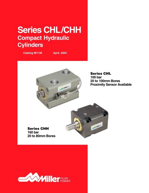
<strong>Series</strong> <strong>CHL</strong>/<strong>CHH</strong>Compact HydraulicCylindersCatalog M1136 April, 2003<strong>Series</strong> <strong>CHL</strong>100 bar20 to 100mm BoresProximity Sensor Available<strong>Series</strong> <strong>CHH</strong>160 bar20 to 80mm Bores
Catalog M1136Table of ContentsCompact Hydraulic Cylinders<strong>Series</strong> <strong>CHL</strong> & <strong>CHH</strong>Page No.Standard Specifications .................................................................................................................................. 2Operating Pressure Range ............................................................................................................................. 2Optional Seal Materials ................................................................................................................................... 2Standard Cylinder Stroke List......................................................................................................................... 3Minimum Cylinder Stroke with Switch ............................................................................................................ 3T Mount Dimensions for <strong>CHH</strong> and <strong>CHL</strong> .................................................................................................. 4 - 5C Mount Dimensions for <strong>CHH</strong> .................................................................................................................. 6 - 7Foot Mount Installation ................................................................................................................................... 8Lock Nuts ......................................................................................................................................................... 8CA Mount ......................................................................................................................................................... 9J Mount .......................................................................................................................................................... 10H Mount ......................................................................................................................................................... 11Standard Cylinder Weight Table ................................................................................................................... 12Switch Specifications ............................................................................................................................. 13 - 15Installation, Maintenance, and Handling Precautions ................................................................................. 16Permissible Energy of Inertia Table ............................................................................................................. 17Theoretical Push and Pull Forces ................................................................................................................ 17How to Order ................................................................................................................................................. 18Safety Guidelines .......................................................................................................................................... 19Offer of Sale .................................................................................................................................................. 201Miller <strong>Fluid</strong> PowerDes Plaines, ILToronto, Ontario Canada
Catalog M1136SpecificationsCompact Hydraulic Cylinders<strong>Series</strong> <strong>CHL</strong> & <strong>CHH</strong>Standard Specifications<strong>CHL</strong><strong>CHH</strong>Nominal Operating Pressure ................................. 100 bar (1500 psi)* ..........................160 bar (2300 psi)Minimum Operating Pressure ...................................... 3.4 bar (50 psi) ............................... 3.4 bar (50 psi)Available Bores .............................. 20, 25, 32, 40, 50, 63, 80, 100 mm ........ 20, 25, 32, 40, 50, 63, 80 mmMagnetic Piston for Sensors .................................................. Standard .................................. Not AvailableCylinder Body Material ................................................ Aluminum Alloy ........................... Black Oxide SteelAvailable Mounting Styles ................................. 4: Style T, CA, J, and H .............. 5: Styles T, C, CA, J and HSingle and Double Rod Construction ............................................. Yes .................................................. YesOperating Temperature ............................... -10 to +70°C (14 to 158°F) ...........-10 to +120°C (14 to 248°F)Recommended <strong>Fluid</strong> .......................... Petroleum based hydraulic oil** .... Petroleum based hydraulic oil**Stroke Tolerance ........................................................... +.8 mm (.01 in.) .............................. +.8 mm (.01 in.)* Refer to the Operating Pressure Range graph for the <strong>CHL</strong> cylinder below. The life of the cylinder is impactedas the pressure increases above nominal. Please review your application, pressure ratings, and frequencyof actuation.**Special seals are offered for other fluid mediums or high temperature use. Please refer to the table below.18Operating Pressure RangePRESSURE(MPa)16141210OPERATINGPRESSURE RANGE1050 100 500 1000FREQUENCY OF ACTUATION (x 10,000)Cylinder Operating Temperatures with Various <strong>Fluid</strong>s and Seal Materials<strong>Fluid</strong> Medium Seal Material Temperature RangePetroleum-based fluidFluorocarbon 0 to +100° C (14 to 212° F)Hydrogenated nitrile-10 to 120° C (14°F to 248°F)Water-glycol fluid Hydrogenated nitrile -10 to +100° C (14 to 212° F)Phosphate ester fluid Fluorocarbon 0 to +100° C (14 to 212° F)2Miller <strong>Fluid</strong> PowerDes Plaines, ILToronto, Ontario Canada
Catalog M1136Cylinder Stroke ListsCompact Hydraulic Cylinders<strong>Series</strong> <strong>CHL</strong> & <strong>CHH</strong>Stock Cylinder Stroke List<strong>Series</strong><strong>CHH</strong>TypeSingle rodDouble rodMountingStyleTCTCBore 5 10 15 20 25 30 40 50 60 70 80 90 100 Bore20 20NA25 2532 3240 S4050 S5063 6380 8032 32S 140NA4050 50S 263 6320 20NA25 2532 3240 S4050 NS5063 6380 8032 32S 140NA4050 50S 263 63<strong>Series</strong><strong>CHL</strong>Stroke in mmTypeSingle rodDouble rodMountingStyleTTBore 5 10 15 20 25 30 40 50 60 70 80 90 100 Bore20 20NA25 2532 3240 40S50 50S63 6380 80100 10020 20NA25 2532 3240 4050 50SNS63 6380 80100 100S=Stocked, NS=Not Stocked – Lead times will be longer than standardNA=Not Available!IMPORTANT:20 and 25 mm bore cylinders are not available with SAE ports.132 and 40 mm bore “C” Mount cylinders with SAE ports are not available.250 and 63 mm bore “C” Mount cylinders with SAE ports are made-to-order.Non-standard strokes and strokes over 100mm are a special request. Consult factory for pricing and dimensionalinformation. Lead times will be longer than standard.Consult the table below for minimum stroke lengths when choosing a cylinder with switches.Minimum Cylinder Stroke with SwitchAll BoresInstall 1 Switch5mmInstall 2 Switches10mm3Miller <strong>Fluid</strong> PowerDes Plaines, ILToronto, Ontario Canada
Catalog M1136T Mount Double Rod EndCompact Hydraulic Cylinders<strong>Series</strong> <strong>CHL</strong> & <strong>CHH</strong>20 through 100mm BoreRod End Style 9Rod End Style 9A1/8 NPTOnlyAKKMMMMMMERCWFLB + StrokeZJ + Stroke1/8 NPTOnlyCCWF LD + Stroke WF + StrokeZM + 2 x StrokeEEDRERod End Style 8 or 5A WFFB - 4 HolesFC CounterboreDia x FD DeepBoth EndsYP + StrokeNBNBC20 and 25mm Bore<strong>Series</strong> <strong>CHH</strong> Port Detail5 and 10mm strokes onlyYP + StrokeMMCCDWidthAcrossFlatsT Mount Double Rod EndNotes: Style 5 is the recommended thread length of a Style 8 Rod End when usedwith a lock nut.Dimensions other than threads are in millimeters.100mm bore is in <strong>CHL</strong> series only.Depiction of <strong>Series</strong> <strong>CHH</strong> cylinder. <strong>Series</strong> <strong>CHL</strong> cylinders will have switch grooves.Rod DimensionsBoreRodDia.MMThreadStyle 8 or 5CCStyle 9KKStyle 8AStyle 5AStyle 9A C D WF20 12 7/16-20 1/4-20 15 30 10 6 10 825 14 1/2-20 3/8-24 18 35 12 6 12 832 18 9/16-18 7/16-20 25 40 15 7 14 1040 22 3/4-16 5/8-18 30 48 20 7 19 1050 28 7/8-14 3/4-16 35 55 24 8 24 1163 36 1 1/8-12 1-14 45 65 33 9 30 1380 45 1 3/8-12 1 1/4-12 60 80 36 14 41 17100 56 1 1/2-12 1 7/8-12 75 95 45 22 50 26EE NB (<strong>CHH</strong>)Envelope and Mounting DimensionsNB (<strong>CHL</strong>)Add StrokeBore Y NPT SAE NPT SAE NPT SAE E R FB FC FD P (NPT) P (SAE) LD ZM20 28.5 1/8 - - - 3 - 44 30 5.5 9.5 5.4 13 - 54 7025 28.5 1/8 - - - 6 - 50 36 5.5 9.5 5.4 15 - 56 7232 38 1/4 4 10 12 10 12 62 47 6.6 11 6.5 16 16 72 9240 37 1/4 4 10 12 10 12 70 52 9 14 8.6 18 18 72 9250 39 1/4 4 10 13 10 13 80 58 11 17.5 10.8 19 19 75 9763 43 1/4 4 10 14 10 14 94 69 14 20 13 22 22 82 10880 52 3/8 6 15 20 15 20 114 86 16 23 15.2 25 25 95 129100 68 3/8 6 - - 15 15 138 106 18 26 17.5 24 24 108 1605Miller <strong>Fluid</strong> PowerDes Plaines, ILToronto, Ontario Canada
Catalog M1136C Mount Single Rod EndCompact Hydraulic Cylinders<strong>Series</strong> <strong>CHH</strong>32 through 63mm BoreRod End Style 9AUSTSKKMMKEYECWFKB KALB + StrokeZJ + StrokeKC + StrokeLH ±0.06DKD* Key Included With CylinderSB - 4 HolesSC CounterboreDia x SD DeepBoth Ends20SS + STROKESWEENBNBRod End Style 8 or 5A WFCMMYP + StrokeCCDWidthAcrossFlatsC Mount Single Rod EndRod DimensionsRod Thread PortsDia. Style 8 or 5 Style 9 Style 8 Style 5 Style 9 EE NBBore MM CC KK A A A C D WF NPT SAE NPT SAE32 18 9/16 – 18 7/16 – 20 25 40 15 7 14 10 1/4 — 10 —40 22 3/4 – 16 5/8 – 18 30 48 20 7 19 10 1/4 — 10 —50 28 7/8 – 14 3/4 – 16 35 55 24 8 24 11 1/4 4 10 1363 36 1-1/8 – 12 1 – 14 45 65 33 9 30 13 1/4 4 10 14NOTE: Style 5 is the recommended thread when a lock nut is used.Dimensions, other than threads, are in millimeters.Envelope and Mounting DimensionsAdd StrokeBore E LH KA KB KC KD SS SW TS US Y P (NPT) P (SAE) LB ZJ32 56 25 12 28 14 63 24 10 56 70 38 14 — 54 6440 64 29 12 28 15 70 23 12 62 80 37 16 — 55 6550 74 34 14 29 17 80 27 13 74 94 39 19 16 60 7163 89 42 16 31 20 100 32 15 90 114 43 24 23 67 80NOTE: The LH dimension has a tolerance of ± .06mmMounting Hole DimensionsBore SB SC SD32 9 14 840 11 17.5 10.850 14 20 1363 16 23 15.26Miller <strong>Fluid</strong> PowerDes Plaines, ILToronto, Ontario Canada
Catalog M1136C Mount Double Rod EndCompact Hydraulic Cylinders<strong>Series</strong> <strong>CHH</strong>32 through 63mm BoreRod End Style 9AUSTSKKMMMMECWFKB KALB + StrokeZM + 2 x StrokeKEYKC + StrokeLH ±0.06DKD* Key Included With CylinderSB - 4 HolesSC CounterboreDia x SD DeepBoth EndsSS + STROKE20 20EENBNBRod End Style 8 or 5A WFCMMYP + StrokeCCDWidthAcrossFlatsC Mount Double Rod EndRod DimensionsRod Thread PortsDia. Style 8 or 5 Style 9 Style 8 Style 5 Style 9 EE NBBore MM CC KK A A A C D WF NPT SAE NPT SAE32 18 9/16 – 18 7/16 – 20 25 40 15 7 14 10 1/4 — 10 —40 22 3/4 – 16 5/8 – 18 30 48 20 7 19 10 1/4 — 10 —50 28 7/8 – 14 3/4 – 16 35 55 24 8 24 11 1/4 4 10 1363 36 1-1/8 – 12 1 – 14 45 65 33 9 30 13 1/4 4 10 14NOTE: Style 5 is the recommended thread when a lock nut is used.Dimensions, other than threads, are in millimeters.Envelope and Mounting DimensionsAdd StrokeBore E Y LH KA KB KC KD SS TS US P (NPT) P (SAE) LB ZJ32 56 38 25 12 28 14 63 32 56 70 16 — 72 9240 64 37 29 12 28 15 70 32 62 80 18 — 72 9250 74 39 34 14 29 17 80 35 74 94 19 19 75 9763 89 43 42 16 31 20 100 42 90 114 22 22 82 108NOTE: The LH dimension has a tolerance of ± .06mmMounting Hole DimensionsBore SB SC SD32 9 14 840 11 17.5 10.850 14 20 1363 16 23 15.27FIRST ANGLEVIEW PROJECTIONMiller <strong>Fluid</strong> PowerDes Plaines, ILToronto, Ontario Canada
Catalog M1136Foot Mount InstallationCompact Hydraulic Cylinders<strong>Series</strong> <strong>CHL</strong> & <strong>CHH</strong>Installation With a KeyKey Included With Cylinder(C Mounting Only)Dimensional TableKey Nominal Dimension Key Groove DimensionBore b x h x l b1 t1 r100.043φ32 12 x 8 x 63 12- 5.00φ40 12 x 8 x 70 12-0.0435.0 0 0.250+0.2φ50 14 x 9 x 80 14- 5.5~0.400.0430φ63 16 x 10 x 100 16- 6.00.043+0.20+0.20+0.20When installing a foot Mount (C Mount)cylinder, refer to the dimensional table forthe correct key and machined groovedimensions.Installation Without a KeyRecommended Key Groove Dimensionb1Front Block(For Retracting)Rear Block(For Extending)r1 r1 t1Block And Key Dimensions Must Be Identical To One AnotherWhen installing a cylinder without a key, besure to place blocks at each end. Bolts alonemay not support the cylinder’s force, whichcould result in damage to the bolts.Lock NutsKKCHBLock NutParts NumberB C H KKLN-20 11/16 0.794 3/8 7/16 – 20 UNFLN-25 3/4 0.866 7/16 1/2 – 20 UNFLN-01 7/8 1.010 31/64 9/16 – 18 UNFLN-02 1-1/8 1.299 41/64 3/4 – 16 UNFLN-03 1-5/16 1.516 3/4 7/8 – 14 UNFLN-04 1-11/16 1.949 31/32 1-1/8 – 12 UNFLN-05 2-1/16 2.382 1-11/64 1-3/8 – 12 UNFLN-06 2-15/16 3.392 1-27/32 1-7/8 – 12 UNFDimensions are in inches.8Miller <strong>Fluid</strong> PowerDes Plaines, ILToronto, Ontario Canada
Catalog M1136CA MountCompact Hydraulic Cylinders<strong>Series</strong> <strong>CHL</strong> & <strong>CHH</strong>CA Mount Single Rod EndLB + STROKEEKKROD ENDSTYLE 9MMEHDCWSUXSSS + STROKEZB + STROKESUSYLHST4-SBTSUSCA Mount Single Rod End & Double Rod EndSingle Rod End Double Rod EndEnvelope and Mounting DimensionsAddAdd Stroke Add Stroke 2X StrokeBore E EH LH SB ST SU SY TS US XS SS LB ZB SV LG ZM20 44 46 24±0.15 6.6 12 15 7.5 58 70 15.5 58 73 81 69 84 10025 50 52 27±0.15 6.6 12 15 7.5 64 76 15.5 60 75 83 71 86 10232 62 66 35±0.15 9 16 20 10 79 94 20 74 94 104 92 112 13240 70 72.5 37.5±0.15 11 20 20 10 90 108 20 75 95 105 92 112 13250 80 85 45±0.15 14 24 25 12.5 104 126 23.5 85 110 121 100 125 14763 94 97 50±0.15 16 30 25 12.5 121 146 23.5 92 117 130 107 132 15880 114 117 60±0.25 18 35 30 15 144 172 32 108 138 155 125 155 189100 138 140 71±0.25 22 43 35 17.5 174 208 43.5 131 166 192 143 178 230CA Mount Double Rod EndLG + STROKEEKKMMMMEHDCWSUXSSV + STROKEZM + 2 X STROKESUW + STROKEXS + STROKECLHST4-SBTSUSRod End Style 8 or 5MMCCADWidthAcrossFlatsCWRod DimensionsRod ThreadBoreDia.MMStyle 8 or 5CCStyle 9KKStyle 8AStyle 5AStyle 9A C D W20 12 7/16-20 1/4-20 15 30 10 6 10 825 14 1/2-20 3/8-24 18 35 12 6 12 832 18 9/16-18 7/16-20 25 40 15 7 14 1040 22 3/4-16 5/8-18 30 48 20 7 19 1050 28 7/8-14 3/4-16 35 55 24 8 24 1163 36 1 1/8-12 1-14 45 65 33 9 30 1380 45 1 3/8-12 1 1/4-12 60 80 36 14 41 17100 56 1 1/2-12 1 7/8-12 75 95 45 22 50 26Notes: Style 5 is the recommended thread length of a Style 8 Rod End when usedwith a lock nut.Dimensions other than threads are in millimeters.100mm bore is in <strong>CHL</strong> series only.9Miller <strong>Fluid</strong> PowerDes Plaines, ILToronto, Ontario Canada
Catalog M1136J MountCompact Hydraulic Cylinders<strong>Series</strong> <strong>CHL</strong> & <strong>CHH</strong>J Mount Single Rod EndER4-FBMMFERDCW F TFKKROD ENDUFLB + STROKESTYLE 9J Mount Single Rod EndEnvelope and Mounting DimensionsADD STROKEBore W E F FB FE R TF UF LB20 8 44 10 5.5 46 30 60 75 5325 8 50 10 5.5 52 36 66 80 5532 10 62 15 6.6 62 40 80 95 6940 10 70 20 11 70 46 96 118 7550 11 80 20 14 85 58 108 135 8063 13 94 20 16 98 65 124 150 8780 17 114 25 18 118 87 154 185 103100 26 138 30 22 150 109 190 230 126See opposite page for rod dimensions.J Mount Double Rod EndERKKROD ENDSTYLE 9MMMMFERDCWFLG + STROKEZM + 2 x STROKEW + STROKE4-FBTFUFJ Mount Double Rod EndADD STROKE ADD 2X STROKEBore W E F FB FE R TF UFLGZM20 8 44 10 5.5 46 30 60 75 64 8025 8 50 10 5.5 52 36 66 80 66 8232 10 62 15 6.6 62 40 80 95 87 10740 10 70 20 11 70 46 96 118 92 11250 11 80 20 14 85 58 108 135 95 11763 13 94 20 16 98 65 124 150 102 12880 17 114 25 18 118 87 154 185 120 154100 26 138 30 22 150 109 190 230 138 190See opposite page for rod dimensions.Envelope and Mounting Dimensions10Miller <strong>Fluid</strong> PowerDes Plaines, ILToronto, Ontario Canada
Catalog M1136H MountCompact Hydraulic Cylinders<strong>Series</strong> <strong>CHL</strong> & <strong>CHH</strong>H Mount Single Rod EndERKKROD ENDSTYLE 9MMFERDCWFLB + STROKEF4-FBTFUFH Mount Single Rod EndEnvelope and Mounting DimensionsBore WF E F FB FE R TF UFADD STROKELB20 8 44 10 5.5 46 30 60 75 5325 8 50 10 5.5 52 36 66 80 5532 10 62 15 6.6 62 40 80 95 6940 10 70 20 11 70 46 96 118 7550 11 80 20 14 85 58 108 135 8063 13 94 20 16 98 65 124 150 8780 17 114 25 18 118 87 154 185 103100 26 138 30 22 150 109 190 230 126Rod End Style 8 or 5MMCCADWidthAcrossFlatsCWRod DimensionsRod ThreadBoreDia.MMStyle 8 or 5CCStyle 9KKStyle 8AStyle 5AStyle 9A C D W20 12 7/16-20 1/4-20 15 30 10 6 10 825 14 1/2-20 3/8-24 18 35 12 6 12 832 18 9/16-18 7/16-20 25 40 15 7 14 1040 22 3/4-16 5/8-18 30 48 20 7 19 1050 28 7/8-14 3/4-16 35 55 24 8 24 1163 36 1 1/8-12 1-14 45 65 33 9 30 1380 45 1 3/8-12 1 1/4-12 60 80 36 14 41 17100 56 1 1/2-12 1 7/8-12 75 95 45 22 50 26Notes: Style 5 is the recommended thread length of a Style 8 Rod End when usedwith a lock nut.Dimensions other than threads are in millimeters.100mm bore is in <strong>CHL</strong> series only.11Miller <strong>Fluid</strong> PowerDes Plaines, ILToronto, Ontario Canada
Catalog M1136Cylinder WeightsCompact Hydraulic Cylinders<strong>Series</strong> <strong>CHL</strong> & <strong>CHH</strong>Standard Cylinder Weight Table<strong>Series</strong><strong>CHH</strong>TypeSingle rodDouble rodMountingStyleTCTCUnit: kgBore 5 10 15 20 25 30 40 50CA J and HMounting Mounting20 0.59 0.65 0.72 0.78 0.85 0.91 1.04 1.17 0.46 0.2525 0.81 0.89 0.97 1.05 1.13 1.21 1.37 1.53 0.58 0.332 1.51 1.63 1.76 1.88 2.01 2.13 2.38 2.63 1.09 0.6240 1.87 2.02 2.17 2.32 2.47 2.62 2.92 3.22 1.42 1.1650 2.62 2.80 2.99 3.17 3.36 3.54 3.91 4.28 2.43 1.663 3.97 4.20 4.44 4.67 4.91 5.14 5.61 6.08 3.3 2.0280 6.89 7.22 7.56 7.89 8.23 8.56 9.23 9.90 5.86 3.7732 1.49 1.62 1.76 1.89 2.03 2.16 2.43 2.7040 1.92 2.09 2.26 2.43 2.60 2.77 3.11 3.4550 2.78 3.00 3.22 3.44 3.60 3.88 4.32 4.76-63 4.40 4.71 5.02 5.33 5.64 5.95 6.57 7.1920 0.74 0.81 0.88 0.95 1.02 1.09 1.23 1.37 0.46 0.2525 1.01 1.09 1.18 1.26 1.35 1.43 1.60 1.77 0.58 0.332 1.71 1.95 1.95 2.07 2.19 2.31 2.55 2.79 1.09 0.6240 2.20 2.36 2.52 2.68 2.84 3.00 3.32 3.64 1.42 1.1650 2.87 3.05 3.23 3.41 3.59 3.77 4.13 4.49 2.43 1.663 4.23 4.43 4.64 4.84 5.05 5.25 5.66 6.07 3.3 2.0280 7.99 8.40 8.82 9.23 9.65 10.06 10.89 11.72 5.86 3.7732 1.95 2.09 2.23 2.37 2.51 2.65 2.93 3.2140 2.56 2.74 2.92 3.10 3.28 3.46 3.82 4.1850 3.48 3.72 3.96 4.20 4.44 4.68 5.16 5.64-63 5.33 5.67 6.01 6.35 6.69 7.03 7.71 8.39<strong>Series</strong><strong>CHL</strong>TypeSingle rodDouble rodMountingStyleTTBore 5 10 15 20 25 30 40 50CA J and HMounting Mounting20 0.30 0.29 0.31 0.33 0.36 0.38 0.42 0.46 0.46 0.2525 0.42 0.41 0.44 0.46 0.49 0.52 0.57 0.63 0.58 0.3032 0.70 0.75 0.80 0.84 0.89 0.93 1.02 1.11 1.09 0.6240 0.93 0.99 1.05 1.11 1.16 1.22 1.33 1.45 1.42 1.1650 1.14 1.49 1.57 1.64 1.72 1.79 1.94 2.09 2.43 1.6063 2.20 2.30 2.40 2.51 2.61 2.72 2.93 3.14 3.30 2.0280 3.98 4.13 4.28 4.44 4.60 4.75 5.07 5.38 5.86 3.77100 7.38 7.61 7.84 8.07 8.30 8.53 8.98 9.44 9.99 7.2320 0.40 0.41 0.44 0.46 0.48 0.51 0.46 0.25-25 0.58 0.56 0.60 0.63 0.66 0.69 0.58 0.3032 1.09 1.14 1.19 1.25 1.30 1.36 1.47 1.58 1.09 0.6240 1.39 1.46 1.53 1.60 1.67 1.74 1.88 2.02 1.42 1.1650 2.02 2.12 2.22 2.32 2.42 2.52 2.71 2.91 2.43 1.6063 3.05 3.20 3.34 3.49 3.63 3.78 4.07 4.35 3.30 2.0280 5.60 5.82 6.03 6.25 6.47 6.69 7.12 7.55 5.86 3.77100 10.27 10.59 10.92 11.24 11.57 11.89 12.54 13.19 9.99 7.23Switch Weight: AX115 and AX215 = 0.16 kgT0H3 and T2H3 = 0.05 kg12Miller <strong>Fluid</strong> PowerDes Plaines, ILToronto, Ontario Canada
Catalog M1136SwitchesCompact Hydraulic Cylinders<strong>Series</strong> <strong>CHL</strong> & <strong>CHH</strong>Working DescriptionThe reed switch and indicating lamp is mounted on the cylinder body. When the magnet-equipped piston passes, the reedswitch actuates and the cylinder stroke position is detected.CylinderMoving DirectionCylinderMoving DirectionWorking RangeABReverse DirectionDifference 1mmCAWhen the piston moves in the > direction and the magnetarrives at position “A,” the reed switch actuates. The switchremains on from “A” to “B.” This is called the working range.When the piston reaches position “A” and then returns in thereverse direction
Catalog M1136Switch AdjustmentCompact Hydraulic Cylinders<strong>Series</strong> <strong>CHL</strong> & <strong>CHH</strong>How to Adjust Switch PositionsBracket Set Screw (M3)Bracket (T10)Slide Switch To Desired Position1. Loosen the bracket set screw and place the bracket in the center of the switch.2. With the switch and bracket assembled, insert it into the switch installation area of the cylinder body.3. Slide the switch to the desired position. The center is the most stable position.4. When the cylinder stroke end is selected, install the switch at dimension UX (best position setting).5. After sliding the switch to the desired position, tighten the bracket set screw to approximately 0.4 N•m.NOTE: If the clamp is not torqued properly, the position of the switch may shift or the switch itself may become damaged.Switch Installation Dimensions (both stroke ends)<strong>CHL</strong> Single Rod TypeUnit:mmSwitchTypeT0H3T2H3AX115AX215Bore UX1 UX2 RV20 13 12 2225 14 13 2532 19 17 3740 20 17 4150 22 20 4663 24 25 5480 30 30 63100 36 42 75UX1UX2RV<strong>CHL</strong> Double Rod TypeUnit:mmSwitchType Bore UX1 UX2 RVT0H3 20 13 23 22T2H3 25 14 24 2532 19 35 3740 20 34 41AX115 50 22 35 46AX215 63 24 40 5480 30 47 63100 36 53 75UX1UX2RV14Miller <strong>Fluid</strong> PowerDes Plaines, ILToronto, Ontario Canada
Catalog M1136Switch Handling InstructionsCompact Hydraulic Cylinders<strong>Series</strong> <strong>CHL</strong> & <strong>CHH</strong>Precautions for Use1. Do not apply the reed switch to loads which exceed therated voltage / current and load capacity.2. Do not connect the reed switch directly with the powersupply. Always connect with a specific load such as arelay or sequencer.3. Provide a protective circuit parallel to the load for switchprotection for high surge voltages generated near thepower supply or when coils generate high surge voltages(relay approx. 4VA or more).Installing Location1. Use iron plate as magnetic shielding in locations withthe strong ambient magnetic field.Shield PlateDC - ACReed SwitchRCondenser (0.1 µF)Resistance (1 kΩ)Magnetic Field Origin+DC - ACReed SwitchRDiodeProtective Circuit(SK-100)Diode(200V1A And Over)2. Do not bring the strong magnetic bodies (iron, etc.) nearthe cylinder body and switch. As a rule, such materialsshall be kept over 10mm from the switch.-DC - ACReed SwitchRSurgeAbsorberSurge AbsorberDC24V Varitus Voltage Approx. 47VDC48V Varitus Voltage Approx. 100VDC100V Varitus Voltage Approx. 270VOver 0.39"(10mm)4. If the working voltage / current of the switch isinsufficient, the operation check lamp may not light up.Wiring• Do not connect switches in series. The operation checklamp may not light up or loads may not work due to thevoltage drop of the switch.• Do not connect switches in parallel that have anindicating light. Signals output normally, but the lampmay not light up.• Keep the switch cord away from the power supply ofother electric appliances. Switches and loads areaffected by the induction current if it is bundled or wirednear the power supply• Connect the white cord with side and the black cordwith side if the switch with indicating lamp is usedwith direct current.• In the case of capacitance loads (condensers, etc.) orswitch cords of 10m or more, inrush currents may begenerated that cause the switch to fail. Provide thegreatest resistor in series that the circuit will allow asclose to the switch as possible. If the resistance is toohigh, the load device may not work.• Never use incandescent light bulbs in the circuit with thereed switches. High inrush loads will cause switchfailure.Switch Temperature RangeMagnetic Substance(Iron, etc.)3. The interval shall be kept over 15mm when multipleswitch-set cylinders are used adjacently. Switches mayperceive the magnet of the above cylinder inadvertently.–10 to 70°C (–14 to 158°F)Over 0.59"(15mm)Subject SwitchSwitch Switch Type Load Voltage Range Load Current Range Power Rating LED Cord Length <strong>CHL</strong> Cylinder Bore5-30VDC 5-40 mA DC 1.5W DCAX115 ReedON: Red 5 m32-1005-120VAC 5-20 mA AC 2VA ACHall Effect,AX2155-30VDC 5-40 mA DC - Red & Green 5 m 32-100NPN Only12-24VDC 5-50 mA DC 1.5W DCT0H3 ReedON: Red 3 m20, 25100VAC 7-20 mA AC 2VA ACHall Effect,T2H310-30VDC 5-20 mA DC - Red & Green 3 m20, 25NPN Only15Miller <strong>Fluid</strong> PowerDes Plaines, ILToronto, Ontario Canada
Catalog M1136Handling PrecautionsCompact Hydraulic Cylinders<strong>Series</strong> <strong>CHL</strong> & <strong>CHH</strong>Installation and Maintenance• Fully torque machine components to the piston rodshoulder so that no force is applied to the piston rodthread on push applications.• During installation, make adjustments carefullybecause a lateral or eccentric load cannot be applied tothe piston rod.• When operating the cylinder for the first time, be sure tobleed the air from the piping. After bleeding the air,operate the cylinder at low pressure, and graduallyincrease the pressure to reach operating pressure.NOTE: The <strong>CHL</strong> and <strong>CHH</strong> series cylinders are not providedwith air vents. Therefore, bleed the air via the piping.• To install the cylinder, 4 socket head screws (JIS B1176,strength classification of 10.9 or more) shall be used.• When using the mounting bolts, screw 80% or more ofthe threaded portion of bolts into the material to bemounted. The material to be mounted must have thestrength that is equivalent to the SS400 material quality.• To tighten the mounting bolts with nuts, use steel nutswith the strength classification of 6 or more. (However,do not use type 3.)• When threading mounting bolts through the cylinders,be sure to tighten them using the torque valuesindicated in the table below.Cylinder Mounting Bolt Tightening Torque TableTighteningMounting Bolt Size TorqueBore Inch Metric N-m (ft-lbs)20 10 – 24 M5 X 0.8 4.8 (3.54)25 10 – 24 M5 X 0.8 4.8 (3.54)T32 1/4 – 20 M6 X 1 8.1 (5.97)Mount 40 5/16 – 18 M8 X 1.25 20 (14.75)50 3/8 – 16 M10 X 1.5 40 (29.50)63 1/2 – 13 M12 X 1.75 67 (49.42)80 1/2 – 13* M14 X 2 110 (81.14)100 5/8 – 11 M16 X 2 120 (88.51)32 5/16 – 18 M8 X 1.25 20 (14.75)C 40 3/8 – 16 M10 X 1.5 40 (29.50)Mount 50 1/2 – 13 M12 X 1.75 67 (49.42)63 1/2 – 13* M14 X 2 110 (81.14)*When using socket head screws, flat washers are required.Flat washer dimensions: OD must be 0.846" (21.5mm)~0.886" (22.5mm).O.D.Flat WasherSocket Head Screw• The compact design of the piping port allows for fittings(B) with threads in the sizes listed below. An improper fitmay damage the cylinder, resulting in poor performance.Unit: mm (inch)CylinderBoreSize Port Size B20 NPT 1/8 6.3 (0.25)25 NPT 1/8 6.3 (0.25)32 NPT 1/4 9.5 (0.374)40 NPT 1/4 9.5 (0.374)50 NPT 1/4 9.5 (0.374)63 NPT 1/4 9.5 (0.374)80 NPT 3/8 10.5 (0.413)Disassembly and Reassembly PrecautionsCylinders, as shipped from the factory, are not to be disassembledand/or modified. If cylinders require modifications,these modifications must be done at Miller <strong>Fluid</strong> Powerlocations or by Miller <strong>Fluid</strong> Power-certified facilities. It isallowed to disassemble cylinders for the purpose of replacingseals or seal assemblies. However, this work must be done bystrictly following all the instructions provided with the seal kits.Set Screw(Hexagon Wrench)Turning HolePiping Port• After removing the set screw, utilize the turning hole of therod gland to remove the rod gland from the cylinder body.When removing a jig from the rod end threads, burrs maybe created on the width across flats of the rod. In thatcase, use a file to remove the burrs; then, remove the rodgland.• The piston rod and piston cannot be disassembled.• If the cylinder has been disassembled, make sure toreplace all sealing materials (seals and gaskets).• During the reassembly of the cylinder, make sure that nodust or debris such as metal particles enter the cylinder.• A brass plug for protecting the threads of the rod gland islocated below the set screw. This plug must be removedbefore tightening the rod gland.• After tightening the rod gland, install the brass plug that isincluded in the seal set and tighten the set screw.• The general-purpose piston seal, rod seal, dust wiper,and rod gland o-ring can be replaced.B• To tighten the piston rod end threads of the double acting,double rod type, make sure to use the width across flats ofthe rod to be tightened. Because the double rod is joinedby threads, caution shall be taken so that rotational force isnot applied to the rod.16Miller <strong>Fluid</strong> PowerDes Plaines, ILToronto, Ontario Canada
Catalog M1136Permissible Energy of InertiaCompact Hydraulic Cylinders<strong>Series</strong> <strong>CHL</strong> & <strong>CHH</strong>Permissible piston impact speed is limited due to the size of the load attached to the rod end. That speed should be below thebold lines on the chart.<strong>CHL</strong>10050ø 40 ø 32Speed(mm/s)ø 50ø 25 ø 20ø 80 ø 100ø 63108 1 51050100 500 1000Load (kg)<strong>CHH</strong>10050ø 80Speed(mm/s)10ø 20ø 63ø 40ø 25ø 50ø 328 1 510Load (kg)50100 500 1000Theoretical Push and Pull ForcesGeneral FormulaThe cylinder output forces are derived from the formula:F =P x A10000Where F = Force in kN.P = Pressure at the cylinder in bar.A = Effective area of cylinder piston insquare mm.If the piston rod is in compression, use the ‘Push Force’ tablebelow, as follows:1. Identify the operating pressure closest to that required.2. In the same column, identify the force required to movethe load (always rounding up).3. In the same row, look along to the cylinder bore required.Push ForceBore BoreCylinder Push Force in kNø Area 10 40 63 100 125 160mm sq. mm bar bar bar bar bar bar20 314 0.3 1.3 2.0 3.1 3.9 5.025 491 0.5 2.0 3.1 4.9 6.1 7.932 804 0.8 3.2 5.1 8.0 10.1 12.940 1257 1.3 5.0 7.9 12.6 15.7 20.150 1964 2.0 7.9 12.4 19.6 24.6 31.463 3118 3.1 12.5 19.6 31.2 39.0 49.980 5027 5.0 20.1 31.7 50.3 62.8 80.4100 7854 7.9 31.4 49.5 78.5 98.2 125.7If the cylinder envelope dimensions are too large for theapplication, increase the operating pressure, if possible,and repeat the exercise.If the piston rod is in tension, use the ‘Deduction for PullForce’ table. The procedure is the same but, due to thereduced area caused by the piston rod, the force availableon the ‘pull’ stroke will be smaller. To determine the pull force:1. Follow the procedure for ‘push’ applications asdescribed above.2. Using the ‘pull’ table, identify the force indicatedaccording to the rod and pressure selected.3. Deduct this from the original ‘push’ force. The resultant isthe net force available to move the load.If this force is not large enough, repeat the process andincrease the system operating pressure or cylinder diameterif possible. For assistance, contact your local authorizeddistributor.Deduction for Pull ForcePistonRodømmPistonRodAreasq. mmReduction in Force in kN10 40 63 100 125 160bar bar bar bar bar bar12 113 0.1 0.5 0.7 1.1 1.4 1.814 154 0.2 0.6 1.0 1.5 1.9 2.518 255 0.3 1.0 1.6 2.6 3.2 4.122 380 0.4 1.5 2.4 3.8 4.8 6.128 616 0.6 2.5 3.9 6.2 7.7 9.936 1018 1.0 4.1 6.4 10.2 12.7 16.345 1591 1.6 6.4 10.0 15.9 19.9 25.556 2463 2.5 9.9 15.5 24.6 30.8 39.417Miller <strong>Fluid</strong> PowerDes Plaines, ILToronto, Ontario Canada
Catalog M1136How to OrderCompact Hydraulic Cylinders<strong>Series</strong> <strong>CHL</strong> & <strong>CHH</strong>Model Ordering Code for <strong>CHH</strong> & <strong>CHL</strong>32T<strong>CHL</strong>U8X30BoreMountingStylePortTypeRod EndTypeStrokeSpecify:20253240506380100DoubleRodUse: “K” only ifdouble rod cylinderis required.Specify:TCCAJHMountingStyleCode<strong>Series</strong>Specify:U = NPTF PortsT = SAE PortsSAE Ports are notavailable for everybore and mountingcombination. Refer tothe Standard CylinderStroke List table foravailability.20-25mm bores areonly available in NPT.SAE ports arerecommended for32-100mm bores.Special8 = Male9 = Female5 = Long Male3 = Special(see note below)Rod EndType forDoubleRod8 = Male9 = Female5 = Long Male3 = Special(see note below)Specify:51015202530405060708090100<strong>CHL</strong><strong>CHH</strong>Specify S for specialmodification otherthan rod end, andspecify modification.1. Check the Standard Cylinder Stroke List table for standard bore sizes and stroke fabrication ranges. Consult factory forspecial modifications and alternate seal material.2. Strokes over 100mm are a special request. Consult factory for dimensional information.3. Order the AX115 (Reed Type) switch, the AX215 (Hall Effect) switch, the T0H3 (Reed Type) switch, the T2H3 (Hall Effect)switch, or surge absorber for a <strong>CHL</strong> cylinder as another item. List quantities.4. To order thread style 3, specify “3” and give desired dimensions for CC or KK, A, and WF or furnish dimensional sketch.5. Order the lock nuts as another item.Ordering Example:32T<strong>CHL</strong>U8 X 30 with two AX115 switches-represents a 32mm bore <strong>CHL</strong>, T Mount, NPT ports, male rod end,30mm stroke, and two reed type switches18Miller <strong>Fluid</strong> PowerDes Plaines, ILToronto, Ontario Canada
Catalog M1136Cylinder Division Safety GuidelinesCompact Hydraulic Cylinders<strong>Series</strong> <strong>CHL</strong> & <strong>CHH</strong>Cylinder Division Safety Guidelines for Selecting and Using the <strong>CHL</strong> and <strong>CHH</strong> Hydraulic CylindersWARNING: FAILURE OR IMPROPER SELECTION OR IMPROPER USE OF CYLINDERS AND THEIR RELATEDACCESSORIES CAN CAUSE DEATH, PERSONAL INJURY OR PROPERTY DAMAGE.Before selecting or using cylinders or relatedaccessories, it is important that you read, understand,and follow the following safety information.User ResponsibilityDue to a very wide variety of cylinder applications andcylinder operating conditions, Cylinder Division does notwarrant that any particular cylinder is suitable for any specificapplication. The safety guide does not analyze all technicalparameters that must be considered in selecting a product.The hydraulic cylinders outlined in this catalog are designedto Cylinder Division design guidelines and do notnecessarily meet the design guidelines of other agenciessuch as American Bureau of Shipping, ASME PressureVessel Code, etc. The user, through his own analysis andtesting, is solely responsible for:• Making the Final selection of the cylinders and relatedaccessories.• Determining if the cylinders are required to meet specificdesign requirements as required by the Agency(s) orindustry standards covering the design of the user’sequipment.• Assuming that the user’s requirements are met, OSHArequirements are met, and safety guidelines from theapplicable agencies, such as, but not limited to, ANSI, arefollowed and that the use presents no health or safetyhazards.• Providing all the appropriate health and safety warningson the equipment on which the cylinders are used.SealsThe application of cylinders may allow fluids such as cuttingfluids, wash-down fluids, etc., to come in contact with theexternal area of the cylinder. These fluids may attack thepiston rod wiper and or primary seal and must be taken intoaccount.Dynamic seals will wear. The rate of wear will depend onmany operating factors. Wear can be rapid if a cylinder ismisaligned or if the cylinder has been improperly serviced.The user must take seal wear into consideration in theapplication of the cylinders.• Failure of the pressurized fluid delivery system (hoses,fittings, valves, pumps, compressors) which maintaincylinder position.• Catastrophic cylinder seal failure leading to sudden lossof pressurized fluid.• Failure of the machine control system.A lateral or eccentric load cannot be applied to the cylinderpiston rod without causing permanent damage to the cylinder.Careful attention must be paid to cylinder alignment uponinstallation. If these types of additional loads are expected tobe imposed on the piston rod, their magnitude should bemade known to our Engineering Department.For the maximum permissible piston impact speed, pleaserefer to the “Permissible Energy of Inertia” chart.The cylinder user should always make sure that the piston rodis securely attached to the machine member.On occasion, cylinders are ordered with double rods (a pistonrod extending from both ends of the cylinder). In some cases,a stop is threaded on to one of the piston rods and used as anexternal stroke adjuster. On occasions, spacers are attachedto the machine member connected to the piston rod, and alsoused as a stroke adjuster. In both cases, the stops will createa pinch point and the user should consider appropriate use ofguards. If these external stops are not perpendicular to themating contact surface, or if debris is trapped between thecontact surfaces, a bending moment will be placed on thepiston rod, which can lead to piston rod failure. An externalstop will subject the piston rod to impact loading. These two(2) conditions can cause piston rod failure. The use ofexternal stroke adjusters should be reviewed with ourengineering department.Port FittingsHydraulic cylinders applied with meter out or decelerationcircuits are subject to intensified pressure at the piston rodend. The rod end pressure is approximately equal to:operating pressure x effective cap end areaeffective rod end piston areaContact your connector supplier for the pressure rating ofindividual connectors.Piston RodsPossible consequences of piston rod failure or separation ofthe piston rod from the piston include, but are not limited to,are:• Piston rod and/or attached load thrown off at high speed.• High velocity fluid discharge.• Piston rod extending when the pressure is applied in thepiston retract mode.Piston rods or machine members attached to the piston rodmay move suddenly and without warning as a consequenceof other conditions occurring to the machine such as, but notlimited to:• Unexpected detachment of the machine member fromthe piston rod.Cylinder Modifications or RepairsCylinders as shipped from the factory are not to bedisassembled and or modified. If cylinders requiremodifications, these modifications must be done at Miller<strong>Fluid</strong> Power locations or by Miller <strong>Fluid</strong> Power certifiedfacilities. It is allowed to disassemble cylinders for thepurpose of replacing seals or seal assemblies. However, thiswork must be done by strictly following all the instructionsprovided with the seal kits.Mounting RecommendationsAlways mount cylinders using the largest possible hightensile alloy steel socket head screws that can fit in thecylinder mounting holes and torque them to the manufacturer’srecommendations for their size. Refer to theInstallation and Maintenance page.19Miller <strong>Fluid</strong> PowerDes Plaines, ILToronto, Ontario Canada
Catalog M1136Offer of SaleCompact Hydraulic Cylinders<strong>Series</strong> <strong>CHL</strong> & <strong>CHH</strong>The items described in this document and other documents or descriptions provided by the Company, its subsidiaries and itsauthorized distributors, are hereby offered for sale at prices to be established by the Company, its subsidiaries and its authorizeddistributors. This offer and its acceptance by any customer (“Buyer”) shall be governed by all of the following Terms andConditions. Buyer’s order for any such item, when communicated to the Company, its subsidiaries or an authorized distributor(“Seller”) verbally or in writing, shall constitute acceptance of this offer.1. Terms and Conditions of Sale: All descriptions, quotations, proposals,offers, acknowledgments, acceptances and sales of Seller’s products aresubject to and shall be governed exclusively by the terms and conditionsstated herein. Buyer’s acceptance of any offer to sell is limited to theseterms and conditions. Any terms or conditions in addition to, or inconsistentwith those stated herein, proposed by Buyer in any acceptance of an offerby Seller, are hereby objected to. No such additional, different or inconsistentterms and conditions shall become part of the contract between Buyerand Seller unless expressly accepted in writing by Seller. Seller’s acceptanceof any offer to purchase by Buyer is expressly conditional uponBuyer’s assent to all the terms and conditions stated herein, including anyterms in addition to, or inconsistent with those contained in Buyer’s offer.Acceptance of Seller’s products shall in all events constitute such assent.2. Payment: Payment shall be made by Buyer net 30 days from the dateof delivery of the items purchased hereunder. Amounts not timely paid shallbear interest at the maximum rate permitted by law for each month orportion thereof that the Buyer is late in making payment. Any claims byBuyer for omissions or shortages in a shipment shall be waived unlessSeller receives notice thereof within 30 days after Buyer’s receipt of theshipment.3. Delivery: Unless otherwise provided on the face hereof, delivery shallbe made F.O.B. Seller’s plant. Regardless of the method of delivery,however, risk of loss shall pass to Buyer upon Seller’s delivery to a carrier.Any delivery dates shown are approximate only and Seller shall have noliability for any delays in delivery.4. Warranty: Seller warrants that the items sold hereunder shall be freefrom defects in material or workmanship for a period of 18 months from dateof shipment from the Company. THIS WARRANTY COMPRISES THESOLE AND ENTIRE WARRANTY PERTAINING TO ITEMS PROVIDEDHEREUNDER. SELLER MAKES NO OTHER WARRANTY, GUARANTEE,OR REPRESENTATION OF ANY KIND WHATSOEVER. ALL OTHERWARRANTIES, INCLUDING BUT NOT LIMITED TO, MERCHANTABILITYAND FITNESS FOR PURPOSE, WHETHER EXPRESS, IMPLIED, ORARISING BY OPERATION OF LAW, TRADE USAGE, OR COURSE OFDEALING ARE HEREBY DISCLAIMED.NOTWITHSTANDING THE FOREGOING, THERE ARE NO WARRAN-TIES WHATSOEVER ON ITEMS BUILT OR ACQUIRED WHOLLY ORPARTIALLY, TO BUYER’S DESIGN OR SPECIFICATIONS.5. Limitation of Remedy: SELLER’S LIABILITY ARISING FROM OR INANY WAY CONNECTED WITH THE ITEMS SOLD OR THIS CONTRACTSHALL BE LIMITED EXCLUSIVELY TO REPAIR OR REPLACEMENT OFTHE ITEMS SOLD OR REFUND OF THE PURCHASE PRICE PAID BYBUYER, AT SELLER’S SOLE OPTION. IN NO EVENT SHALL SELLERBE LIABLE FOR ANY INCIDENTAL, CONSEQUENTIAL OR SPECIALDAMAGES OF ANY KIND OR NATURE WHATSOEVER, INCLUDINGBUT NOT LIMITED TO LOST PROFITS ARISING FROM OR IN ANY WAYCONNECTED WITH THIS AGREEMENT OR ITEMS SOLD HEREUN-DER, WHETHER ALLEGED TO ARISE FROM BREACH OF CONTRACT,EXPRESS OR IMPLIED WARRANTY, OR IN TORT, INCLUDING WITH-OUT LIMITATION, NEGLIGENCE, FAILURE TO WARN OR STRICTLIABILITY.6. Changes, Reschedules and Cancellations: Buyer may request tomodify the designs or specifications for the items sold hereunder as well asthe quantities and delivery dates thereof, or may request to cancel all orpart of this order, however, no such requested modification or cancellationshall become part of the contract between Buyer and Seller unlessaccepted by Seller in a written amendment to this Agreement. Acceptanceof any such requested modification or cancellation shall be at Seller’sdiscretion, and shall be upon such terms and conditions as Seller mayrequire.7. Special Tooling: A tooling charge may be imposed for any specialtooling, including without limitations, dies, fixtures, molds and patterns,acquired to manufacture items sold pursuant to this contract. Such specialtooling shall be and remain Seller’s property notwithstanding payment ofany charges by Buyer. In no event will Buyer acquire any interest inapparatus belonging to Seller which is utilized in the manufacture of theitems sold hereunder, even if such apparatus has been specially convertedor adapted for such manufacture and notwithstanding any charges paid byBuyer. Unless otherwise agreed, Seller shall have the right to alter, discardor otherwise dispose of any special tooling or other property in its solediscretion at any time.8. Buyer’s Property: Any designs, tools, patterns, materials, drawings,confidential information or equipment furnished by Buyer, or any otheritems which become Buyer’s property, may be considered obsolete andmay be destroyed by Seller after two (2) consecutive years have elapsedwithout Buyer placing an order for the items which are manufactured usingsuch property. Seller shall not be responsible for any loss or damage tosuch property while it is in Seller’s possession or control.9. Taxes: Unless otherwise indicated on the face hereof, all prices andcharges are exclusive of excise, sales, use, property, occupational or liketaxes which may be imposed by any taxing authority upon the manufacture,sale or delivery of the items sold hereunder. If any such taxes mustbe paid by Seller or if Seller is liable for the collection of such tax, the amountthereof shall be in addition to the amounts for the items sold. Buyer agreesto pay all such taxes or to reimburse Seller therefore upon receipt of itsinvoice. If Buyer claims exemption from any sales, use or other tax imposedby any taxing authority, Buyer shall save Seller harmless from and againstany such tax, together with any interest or penalties thereon which may beassessed if the items are held to be taxable.10. Indemnity For Infringement of Intellectual Property Rights: Sellershall have no liability for infringement of any patents, trademarks, copyrights,trade dress, trade secrets or similar rights except as provided in thisPart 10. Seller will defend and indemnify Buyer against allegations ofinfringement of U.S. patents, U.S. trademarks, copyrights, trade dress andtrade secrets (hereinafter “Intellectual Property Rights”). Seller will defendat its expense and will pay the cost of any settlement or damages awardedin an action brought against Buyer based on an allegation that an item soldpursuant to this contract infringes the Intellectual Property Rights of a thirdparty. Seller’s obligation to defend and indemnify Buyer is contingent onBuyer notifying Seller within ten (10) days after Buyer becomes aware ofsuch allegations of infringement, and Seller having sole control over thedefense of any allegations or actions including all negotiations for settlementor compromise. If an item sold hereunder is subject to a claim that itinfringes the Intellectual Property Rights of a third party, Seller may, at itssole expense and option, procure for Buyer the right to continue using saiditem, replace or modify said item so as to make it noninfringing, or offer toaccept return of said item and return the purchase price less a reasonableallowance for depreciation. Notwithstanding the foregoing, Seller shallhave no liability for claims of infringement based on information providedby Buyer, or directed to items delivered hereunder for which the designsare specified in whole or part by Buyer, or infringements resulting from themodification, combination or use in a system of any item sold hereunder.The foregoing provisions of this Part 10 shall constitute Seller’s sole andexclusive liability and Buyer’s sole and exclusive remedy for infringementof Intellectual Property Rights.If a claim is based on information provided by Buyer or if the design for anitem delivered hereunder is specified in whole or in part by Buyer, Buyershall defend and indemnify Seller for all costs, expenses or judgementsresulting from any claim that such item infringes any patent, trademark,copyright, trade dress, trade secret or any similar right.11. Force Majeure: Seller does not assume the risk of and shall not beliable for delay or failure to perform any of Seller’s obligations by reason ofcircumstances beyond the reasonable control of Seller (hereinafter “Eventsof Force Majeure”). Events of Force Majeure shall include without limitation,accidents, acts of God, strikes or labor disputes, acts, laws, rules orregulations of any government or government agency, fires, floods, delaysor failures in delivery of carriers or suppliers, shortages of materials andany other cause beyond Seller’s control.12. Entire Agreement/Governing Law: The terms and conditions setforth herein, together with any amendments, modifications and any differentterms or conditions expressly accepted by Seller in writing, shallconstitute the entire Agreement concerning the items sold, and there areno oral or other representations or agreements which pertain thereto. ThisAgreement shall be governed in all respects by the law of the State of Ohio.No actions arising out of sale of the items sold hereunder or this Agreementmay be brought by either party more than two (2) years after the cause ofaction accrues.20Miller <strong>Fluid</strong> PowerDes Plaines, ILToronto, Ontario Canada