Machining forces and technological features of cast PA6, POM C ...
Machining forces and technological features of cast PA6, POM C ...
Machining forces and technological features of cast PA6, POM C ...

Create successful ePaper yourself
Turn your PDF publications into a flip-book with our unique Google optimized e-Paper software.
Day <strong>of</strong> Research 2010 – February 10 – Labo Soete, Ghent University, Belgium<br />
Research <strong>of</strong> machining <strong>forces</strong> <strong>and</strong> <strong>technological</strong> <strong>features</strong> <strong>of</strong><br />
<strong>cast</strong> <strong>PA6</strong>, <strong>POM</strong> C <strong>and</strong> UHMW-PE HD 1000.<br />
Róbert Keresztes, Gábor Kalácska<br />
Institute for Mechanical Engineering Technology,<br />
Faculty <strong>of</strong> Mechanical Engineering, Szent István University, Gödöllő, Hungary<br />
www.geti.gek.szie.hu<br />
Abstract Nowadays parts made <strong>of</strong> up-to-date engineering plastics are used more <strong>and</strong> more<br />
in mechanical engineering practice. These machine-elements are produced most frequently<br />
by injection molding or by one cutting process. The injection molding technology are used<br />
generally for great number <strong>of</strong> pieces, in case <strong>of</strong> serial production while cutting processes are<br />
preferred to piece (unit) or smaller number production.<br />
We used lathe <strong>and</strong> measured the main- <strong>and</strong> feeding-directional cutting force at different<br />
engineering polymers (<strong>cast</strong> <strong>PA6</strong>, <strong>POM</strong> C <strong>and</strong> UHMW PE HD 1000). The analysis made can<br />
be well used in practice.<br />
Keywords turning force components, lathe, force measuring, main cutting force<br />
1. INTRODUCTION<br />
Among cutting processes the turning takes place <strong>of</strong>ten. During turning engineering plastics<br />
many problems can arise. Among these one is the splint (continuous chip) forming which can<br />
cause accident <strong>and</strong> can cause failure maybe the total ruin, fracture <strong>of</strong> the cutting tool.<br />
Because <strong>of</strong> this it is important to set the proper cutting parameters by which it is possible<br />
forming elemental or transitional (easily fracture) chip, too.<br />
It is also important to know during cutting the amount <strong>of</strong> the main cutting force. Knowing this<br />
the load <strong>of</strong> cutting tool can be made more constant as well as the remnant stress in the<br />
material chipped can be reduced to minimum in case <strong>of</strong> proper cutting parameters.<br />
2. TESTING METHODS, INSTRUMENTS<br />
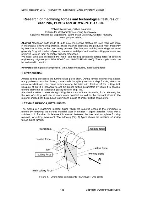
The cutting is a machining method during which the required shape <strong>of</strong> the workpiece is<br />
formed by removing the surplus material layer in smaller – bigger particles (chip) with a<br />
suitable tool. Relative displacement is needed between the tool <strong>and</strong> workpiece for chip<br />
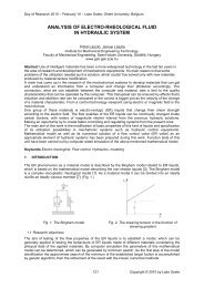
removal, for cutting movement. The following (Fig. 1) figure shows the relations <strong>of</strong> arising<br />
<strong>forces</strong> during turning.<br />
Figure 1. Turning force components (ISO 3002/4, DIN 6584)<br />
136 Copyright © 2010 by Labo Soete
Day <strong>of</strong> Research 2010 – February 10 – Labo Soete, Ghent University, Belgium<br />
Equipment used for tests.<br />
The CNC-lathe, type EMCO COMPACT 5, was used for tests. The equipment can be found in<br />
the laboratory <strong>of</strong> Institute for Mechanical Engineering Technology its programming takes<br />
place <strong>of</strong> G-codes. The photograph <strong>of</strong> the workpiece clamped as well as the shank with straingauges<br />
clamped into tool-box <strong>and</strong> the turning tool can be seen in Figure 2.<br />
Figure 2. The lathe <strong>and</strong> the workpiece clamped<br />
The tool clamping structure used for measuring the <strong>forces</strong> can be seen in Figure 3. The first<br />
section <strong>of</strong> the Figure shows the 3D-model.<br />
Figure 3. The force measuring shank model <strong>and</strong> its real picture<br />
2-2 pcs. strain gauges are fixed at every side. Coupling the strain gauges into total (full) –<br />
bridge those is a possibility measuring the <strong>forces</strong> arising in two directions. To measure the<br />
main cutting force F v (tangential) arising from the movement in vertical plane <strong>of</strong> the tool <strong>and</strong> F f<br />
feeding (axial) force arising from the movement in horizontal plane. A second tool-box is fixed<br />
to 4 pcs. threaded holes on the measuring-shank into which the real cutting tool is fixed. The<br />
strain gauges measure the tangential (lower – upper) <strong>and</strong> the feeding (right side – left side)<br />
<strong>forces</strong> connect to a Spider-8 type measuring amplifier though wires, which amplifier convert<br />
the analogous signals into digital than transmits to the computer. With the help <strong>of</strong> Catman 3.1<br />
program data measured can be seen. The frequency <strong>of</strong> measuring <strong>and</strong> data collecting is 25<br />
Hz.<br />
Materials tested.<br />
The materials tested are those polymer basic types that are <strong>of</strong>ten used in engineering<br />
practice to manufacture machine-elements. Table 1 shows the name <strong>of</strong> product, the whole<br />
name <strong>and</strong> the marks accruing on lather diagrams. The specimens prepared for cutting are<br />
shown in Figure 4.<br />
137 Copyright © 2010 by Labo Soete
Day <strong>of</strong> Research 2010 – February 10 – Labo Soete, Ghent University, Belgium<br />
Serial<br />
number<br />
Table 1. Name <strong>and</strong> mark <strong>of</strong> plastics<br />
Product name [6] Whole name Own mark<br />
1. DOCAMID 6G H<br />
Cast polyamide 6,<br />
(Magnesium)<br />
PA 6G Mg<br />
2. DOCAMID 6G Cast polyamide 6, (Natrium) PA 6G Na<br />
3. DOCACETAL C Polyoximethylene / Polyacetal <strong>POM</strong> C<br />
4. DOCALENE UHMW – Polyethylene HD 1000<br />
1 Figure 4. Specimens 2 prepared for 3 cutting<br />
4<br />
In the Table 2. the more important properties <strong>of</strong> polymers tested can be seen summarized.<br />
Polyme<br />
r<br />
PA 6G<br />
Na<br />
PA 6G<br />
Mg<br />
Strength<br />
[MPa]<br />
Toughnes<br />
s<br />
(Charpy)<br />
[kJ/m 2 ]<br />
Sliding<br />
characteristi<br />
c<br />
(μ)<br />
Table 2. More important properties <strong>of</strong> plastics<br />
Thermoduricity<br />
[°C]<br />
77 - 110 112 0,15 - 0,5 -40 - 140<br />
77 - 110 112 0,15 - 0,5 -40 - 140<br />
<strong>POM</strong> C 70 – 80 8 0,25 – 0,45 5 – 120<br />
HD<br />
1000<br />
20 – 24 no fracture 0,2 – 0,3 -80 – 110<br />
Cutting parameters<br />
Feeding/rev.: f = 0.025, 0.05, 0.1, 0.2 mm/rev.<br />
Depth <strong>of</strong> cut: a = 0.1, 0.25, 0.5, 1, 2 mm<br />
Cutting speed: v = 50, 100, 200<br />
m/min<br />
Hardness<br />
Rockwell<br />
85 – 98<br />
HRC<br />
Rockwell<br />
85 – 98<br />
HRC<br />
Rockwell<br />
86 – 90<br />
HRC<br />
Shore<br />
60 – 65 D<br />
Density<br />
[kg/dm 3 ]<br />
1,15 – 1,6<br />
1,15 – 1,6<br />
Table 3. contains the parameters summarized used at tets. Each cutting speed data<br />
registered means test carried out by one-one material to which belong one feeding <strong>and</strong> one<br />
depth <strong>of</strong> cut. This gives 60 measuring by each material.<br />
1,4<br />
0,96<br />
138 Copyright © 2010 by Labo Soete
Day <strong>of</strong> Research 2010 – February 10 – Labo Soete, Ghent University, Belgium<br />
f<br />
a<br />
0,1<br />
mm<br />
0,25<br />
mm<br />
0,5<br />
mm<br />
1<br />
mm<br />
2<br />
mm<br />
50<br />
m/min<br />
50<br />
m/min<br />
50<br />
m/min<br />
50<br />
m/min<br />
50<br />
m/min<br />
Table 3. Cutting speeds in the function <strong>of</strong> feeding <strong>and</strong> depth <strong>of</strong> cut<br />
0,025 mm/rev. 0,05 mm/rev. 0,1 mm/rev. 0,2 mm/rev.<br />
100<br />
m/min<br />
100<br />
m/min<br />
100<br />
m/min<br />
100<br />
m/min<br />
100<br />
m/min<br />
200<br />
m/min<br />
200<br />
m/min<br />
200<br />
m/min<br />
200<br />
m/min<br />
200<br />
m/min<br />
50<br />
m/min<br />
50<br />
m/min<br />
50<br />
m/min<br />
50<br />
m/min<br />
50<br />
m/min<br />
100<br />
m/min<br />
100<br />
m/min<br />
100<br />
m/min<br />
100<br />
m/min<br />
100<br />
m/min<br />
200<br />
m/min<br />
200<br />
m/min<br />
200<br />
m/min<br />
200<br />
m/min<br />
200<br />
m/min<br />
50<br />
m/min<br />
50<br />
m/min<br />
50<br />
m/min<br />
50<br />
m/min<br />
50<br />
m/min<br />
100<br />
m/min<br />
100<br />
m/min<br />
100<br />
m/min<br />
100<br />
m/min<br />
100<br />
m/min<br />
200<br />
m/min<br />
200<br />
m/min<br />
200<br />
m/min<br />
200<br />
m/min<br />
200<br />
m/min<br />
50<br />
m/min<br />
50<br />
m/min<br />
50<br />
m/min<br />
50<br />
m/min<br />
50<br />
m/min<br />
100<br />
m/min<br />
100<br />
m/min<br />
100<br />
m/min<br />
100<br />
m/min<br />
100<br />
m/min<br />
200<br />
m/min<br />
200<br />
m/min<br />
200<br />
m/min<br />
200<br />
m/min<br />
200<br />
m/min<br />
Forming <strong>of</strong> the cutting tool.<br />
The cutting angles <strong>of</strong> high-speed steel (HSS Co5) turning tool have been determined on the<br />
basis <strong>of</strong> technical tables. The relief angle: α 0 = 10˚, the rake angle: γ 0 = 5˚. The grinding <strong>of</strong><br />
turning tool was carried out on pr<strong>of</strong>ile-grinding machine using diamond grinding wheel. The<br />
ready made turning tool can be seen in Figure 5.<br />
rake angle (γ)<br />
relief angle (α)<br />
Figure 5. The bit <strong>of</strong> turning tool used.<br />
3. TEST RESULTS AND THEIR EVALUATIONS<br />
We have measured two-way <strong>forces</strong> during tests. The tangential-directional main cutting force<br />
<strong>and</strong> the axial feeding-directional force. We have grouped the materials by depth <strong>of</strong> cut, by<br />
feeding within on these by cutting speed. Unite these in one file we have got four series main<br />
cutting force <strong>and</strong> the same series feeding-directional cutting force diagrams. We have made<br />
one-one diagram by parameter from these. Figure 6. <strong>and</strong> 7. show one-one sample diagram.<br />
The cutting force given (main or feeding directional) as well as the feeding (f[mm/rev.]), depth<br />
<strong>of</strong> cut (a[mm]) <strong>and</strong> the cutting speed (v[m/min.]) appear in the diagram title. The force values<br />
[N] given appear on the vertical axis, the cutting time [s] appears on the horizontal axis. We<br />
have presented all four materials in one diagram, so it can be well comparing that at same<br />
cutting parameters how great force befalls onto the cutting tool at various materials. Each<br />
colour marks one material according to mark explanation under the diagram. Continuous line<br />
shows the test results. The dotted line shows the average during measuring time given. Its<br />
value can be seen beside the line.<br />
139 Copyright © 2010 by Labo Soete
Feeding-directional cutting force<br />
[N]<br />
Main cutting force [N]<br />
Day <strong>of</strong> Research 2010 – February 10 – Labo Soete, Ghent University, Belgium<br />
8<br />
7<br />
6<br />
PA 6G Mg average;<br />
5,38<br />
Main cutting force diagrams measured<br />
( f = 0,1 mm/rev; a = 0,1 mm; v = 50 m/min )<br />
5<br />
4<br />
3<br />
2<br />
PA 6G Na average;<br />
4,26<br />
<strong>POM</strong> C average;<br />
3,02<br />
1<br />
0<br />
HD 1000 average;<br />
1,46<br />
0 1 2 3 4 5 6 7<br />
cutting time [s]<br />
PA 6G Na <strong>POM</strong> C HD 1000 PA 6G M g<br />
Figure 6. Main cutting force value at materials tested at cutting parameters given.<br />
4<br />
Feeding-directional cutting force diagrams measured<br />
( f = 0,1 mm/rev; a = 0,1 mm; v = 50 m/min )<br />
3<br />
PA 6G Na average;<br />
2,98<br />
2<br />
PA 6G Mg average;<br />
1,75<br />
1<br />
<strong>POM</strong> C average;<br />
0,76<br />
HD 1000 average;<br />
0,19<br />
0<br />
0 1 2 3 4 5 6 7<br />
cutting time [s]<br />
PA 6G Na <strong>POM</strong> C HD 1000 PA 6G M g<br />
Figure 7. Feeding-directional cutting force at materials tested at parameters given.<br />
As each workpiece tested had the same directions the measuring time period was<br />
continuously changing because <strong>of</strong> various feeding <strong>and</strong> cutting speed values. Therefore we<br />
have 7 s –time taken into account at most measuring. In case <strong>of</strong> certain cutting parameters<br />
this value could not be reached, therefore at these parameters the cutting time was reduced<br />
to 4 at one case 2 s respectively. After putting down into each diagram we have presented the<br />
main –<strong>and</strong> feeding- directional cutting <strong>forces</strong> in the function <strong>of</strong> depth <strong>of</strong> cut <strong>and</strong> <strong>of</strong> feeding<br />
from average values belonging to parameters given according to the following samples<br />
(Figure 8 – 11).<br />
140 Copyright © 2010 by Labo Soete
Main<br />
cutting<br />
force [N]<br />
Main<br />
cutting<br />
force [N]<br />
Day <strong>of</strong> Research 2010 – February 10 – Labo Soete, Ghent University, Belgium<br />
PA 6G Mg v = 50 m/min<br />
PA 6G Mg v = 200 m/min<br />
80,00<br />
70,00<br />
60,00<br />
50,00<br />
40,00<br />
30,00<br />
20,00<br />
10,00<br />
0,00<br />
0,1<br />
0,1<br />
0,2<br />
70,00<br />
60,00<br />
50,00<br />
40,00<br />
30,00<br />
20,00<br />
10,00<br />
0,00<br />
0,1<br />
0,1<br />
0,2<br />
0,25<br />
0,5<br />
1<br />
Depth <strong>of</strong> cut [mm]<br />
2<br />
0,025<br />
0,05<br />
Feeding<br />
[mm/rev]<br />
0,25<br />
0,5<br />
1<br />
0,025<br />
Depth <strong>of</strong> cut [mm]<br />
2<br />
0,05<br />
Feeding<br />
[mm/rev]<br />
Figure 8. The value <strong>of</strong> main cutting force in the function <strong>of</strong> depth <strong>of</strong> cut <strong>and</strong> <strong>of</strong> feeding, PA 6G<br />
Mg<br />
Main cutting<br />
force [N]<br />
PA 6G Na v = 50 m/min<br />
Main cutting<br />
force [N]<br />
PA 6G Na v = 200 m/min<br />
70,00<br />
60,00<br />
50,00<br />
40,00<br />
30,00<br />
20,00<br />
10,00<br />
0,00<br />
0,1<br />
0,25<br />
0,5<br />
Depth <strong>of</strong> cut [mm]<br />
1<br />
2<br />
0,025<br />
0,05<br />
0,1<br />
0,2<br />
Feeding<br />
[mm/rev]<br />
60,00<br />
50,00<br />
40,00<br />
30,00<br />
20,00<br />
10,00<br />
0,00<br />
0,1<br />
0,25<br />
0,5<br />
Depth <strong>of</strong> cut [mm]<br />
1<br />
2<br />
0,025<br />
0,05<br />
0,1<br />
0,2<br />
Feeding<br />
[mm/rev]<br />
Figure 9. The value <strong>of</strong> main cutting force in the function <strong>of</strong> depth <strong>of</strong> cut <strong>and</strong> <strong>of</strong> feeding, PA 6G<br />
Na<br />
Main cutting<br />
force [N]<br />
<strong>POM</strong> C v = 50 m/min<br />
Main cutting<br />
force [N]<br />
<strong>POM</strong> C v = 200 m/min<br />
60,00<br />
50,00<br />
40,00<br />
30,00<br />
20,00<br />
10,00<br />
0,00<br />
0,1<br />
0,25<br />
0,5<br />
Depth <strong>of</strong> cut [mm]<br />
1<br />
2<br />
0,025<br />
0,05<br />
0,1<br />
0,2<br />
Feeding<br />
[mm/rev]<br />
45,00<br />
40,00<br />
35,00<br />
30,00<br />
25,00<br />
20,00<br />
15,00<br />
10,00<br />
5,00<br />
0,00<br />
0,1<br />
0,25<br />
0,5<br />
Depth <strong>of</strong> cut [mm]<br />
1<br />
2<br />
0,025<br />
0,05<br />
0,1<br />
0,2<br />
Feeding<br />
[mm/rev]<br />
Figure 10. The value <strong>of</strong> main cutting force in the function <strong>of</strong> depth <strong>of</strong> cut <strong>and</strong> <strong>of</strong> feeding, <strong>POM</strong><br />
C<br />
Main cutting<br />
force [N]<br />
30,00<br />
25,00<br />
20,00<br />
15,00<br />
10,00<br />
5,00<br />
0,00<br />
0,1<br />
0,25<br />
0,5<br />
Depth <strong>of</strong> cut [mm]<br />
1<br />
HD 1000 v = 50 m/min<br />
2<br />
0,025<br />
0,05<br />
0,1<br />
0,2<br />
Feeding<br />
[mm/rev]<br />
Main cutting<br />
force [N]<br />
30,00<br />
25,00<br />
20,00<br />
15,00<br />
10,00<br />
5,00<br />
0,00<br />
0,1<br />
0,25<br />
0,5<br />
1<br />
Depth <strong>of</strong> cut [mm]<br />
HD 1000 v = 200 m/min<br />
2<br />
0,025<br />
0,05<br />
0,1<br />
0,2<br />
Feeding<br />
[mm/rev]<br />
Figure 11. The value <strong>of</strong> main cutting force in the function <strong>of</strong> depth <strong>of</strong> cut <strong>and</strong> <strong>of</strong> feeding, HD<br />
1000<br />
Specific cutting resistance.<br />
Cutting materials the specific cutting resistance (k s ) is an important factor. The following<br />
sample shows its change in the function <strong>of</strong> depth <strong>of</strong> cut <strong>and</strong> <strong>of</strong> feeding (Figure 12).<br />
141 Copyright © 2010 by Labo Soete
Day <strong>of</strong> Research 2010 – February 10 – Labo Soete, Ghent University, Belgium<br />
Figure 12. The value <strong>of</strong> specific cutting resistance in the function <strong>of</strong> depth <strong>of</strong> cut <strong>and</strong> <strong>of</strong><br />
feeding, HD PE 1000<br />
According to the relation to be found in the literature the main cutting force is the function <strong>of</strong><br />
the specific cutting force (or resistance) <strong>and</strong> <strong>of</strong> the chip area. As during measuring we have<br />
also measured the main cutting force, the chip area was given because <strong>of</strong> parameters set, so<br />
the value <strong>of</strong> the specific cutting force can be got by transposing the original relation.<br />
F<br />
v<br />
Fv<br />
N<br />
ks<br />
A ks<br />
a s ks<br />
<br />
2<br />
a s mm<br />
<br />
<br />
<br />
The material tested <strong>and</strong> the cutting speed used occur in the title <strong>of</strong> sample diagram. Beside<br />
the depth <strong>of</strong> cut <strong>and</strong> feeding the specific cutting resistance (y-axis) in N/mm 2 unit can be<br />
found on the datum lines.<br />
Chip pictures (photographs)<br />
The chip removed during machining have been collected <strong>and</strong> photographs have been made.<br />
Based on these the types <strong>of</strong> chips formed can be examined. Figure 13. shows the chip<br />
pictures (splint, continuous chip, transitional platelike, elemental) in the function <strong>of</strong> feeding<br />
<strong>and</strong> depth <strong>of</strong> cut at 50 m/min cutting speed at <strong>POM</strong> C material. It can be established those<br />
parameters at materials in case <strong>of</strong> which chip type meets well the practical requirements.<br />
Elemental<br />
chip<br />
Transitional<br />
platelike<br />
chip<br />
Splint,<br />
continuous<br />
chip<br />
Figure 13. The forming <strong>of</strong> chip picture in the function <strong>of</strong> depth <strong>of</strong> cut <strong>and</strong> <strong>of</strong> feeding,<br />
<strong>POM</strong> C<br />
142 Copyright © 2010 by Labo Soete
Day <strong>of</strong> Research 2010 – February 10 – Labo Soete, Ghent University, Belgium<br />
4. SUMMARY<br />
It can be established from the test results that PA 6G Mg –material proved to be the toughest<br />
from both the cutting force <strong>and</strong> the specific cutting resistance point <strong>of</strong> view. The specific<br />
cutting force decreases substantially by increasing the cutting parameters (feeding, depth <strong>of</strong><br />
cut). Taking into account the chip type formed it can be said that it is a hardly machineable<br />
material. Using the lower feeding (0.025 mm/rev) is suggested.<br />
The PA 6G Na polymer shows a little lower toughness from the cutting force point <strong>of</strong> view, on<br />
the other h<strong>and</strong> in case <strong>of</strong> the specific cutting force it shows already more important change,<br />
approximately it reduces into third. Its value with the increasing <strong>of</strong> feed <strong>and</strong> depth <strong>of</strong> cut does<br />
not decrease such amount as in case <strong>of</strong> Mg-containing material. At cutting the small feeding<br />
(0.025 mm/rev) <strong>and</strong> the greater depth <strong>of</strong> cut (1-2 mm) is suggested.<br />
At <strong>POM</strong> C –material could be observed the further decrease <strong>of</strong> cutting – <strong>and</strong> specific cutting<br />
force. Both decreased into half approximately, but in case <strong>of</strong> latter, similarly finding PA 6G Na<br />
–material, neither here decreased such amount with increasing the feeding <strong>and</strong> depth <strong>of</strong> cut<br />
as at Mg –containing material. From the st<strong>and</strong>point <strong>POM</strong> C had got the most favourable chip<br />
picture among the engineering plastics taking part in tests. Comparing to PA 6G –materials<br />
here is suggested the use <strong>of</strong> greater feeding with increasing depth <strong>of</strong> cut which results more<br />
favourable chip type forming, too.<br />
The smallest cutting <strong>forces</strong> can be measured at HD 1000 –polymer. It can be well observed at<br />
the value <strong>of</strong> the specific cutting resistance that this material has got the lowest toughness.<br />
From the st<strong>and</strong>point <strong>of</strong> turning this is not a favourable material as regarding the chip type<br />
formed is split (continuous chip) in great part <strong>of</strong> cases tested. The analysis made can be well<br />
used in practice. The favourable values <strong>of</strong> feeding, <strong>of</strong> depth <strong>of</strong> cut <strong>and</strong> <strong>of</strong> cutting speed, within<br />
the ranges tested, can be set for cutting materials tested <strong>and</strong> for the favourable chip picture.<br />
REFERENCES<br />
[1] Antal – Fledrich – Kalácska – Kozma: Műszaki műanyagok gépészeti alapjai, Műszaki<br />
műanyagok gépészeti alapjai, Minerva-Sop Bt. Sopron, 1997<br />
[2] Angyal B., Dobor Lné., Palásti K. B., Sipos S. – A Forgácsolás és Szerszámai –<br />
Műszaki Könyvkiadó, Budapest, 1988<br />
[3] Frischerz, Dax, Gundelfinger, Häffher, Itschner, Kotsch, Staniczek – Fémtechnológiai<br />
Táblázatok – B+V Lap- és Könyvkiadó Kft., 1997<br />
[4] Dr. Kalácska Gábor - Műszaki Műanyag Féltermékek Forgácsolása - Quattroplast<br />
Kft., Gödöllő, 2005.<br />
[5] Nagy P. S. – Szerszámgépek, gyártórendszerek – BDMF jegyzet, Budapest, 1997<br />
[6] www.quattroplast.hu<br />
143 Copyright © 2010 by Labo Soete