failure behaviour of preloaded api line pipe threaded connections
failure behaviour of preloaded api line pipe threaded connections
failure behaviour of preloaded api line pipe threaded connections

Create successful ePaper yourself
Turn your PDF publications into a flip-book with our unique Google optimized e-Paper software.
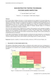
Sustainable Construction and Design 2011FAILURE BEHAVIOUR OF PRELOADED API LINE PIPE THREADEDCONNECTIONSJ. Seys, K. Roeygens, J. Van Wittenberghe, T. Galle, P. De Baets and W. De WaeleGhent University, Laboratory Soete, BelgiumAbstract – This paper reports on numerical and experimental work concerning the fatigue <strong>behaviour</strong> andsealing capacity <strong>of</strong> <strong>threaded</strong> <strong>pipe</strong> <strong>connections</strong> (1” API Line Pipe). Numerical simulations are performedusing Abaqus ® in combination with ThreadGen © . The fatigue life <strong>of</strong> a thick-walled standard coupling isdetermined using a four-point bending test. The corresponding S-N curve is compared to results <strong>of</strong> previouswork on thin-walled specimens. It can be concluded that the standard thick-walled connection has a higherfatigue life than thin-walled ones. In future work, the prediction <strong>of</strong> fatigue life using established multi-axialcriteria will be evaluated. Further, the sealing capacity <strong>of</strong> several couplings will be investigated bysubmitting them to different combinations <strong>of</strong> internal pressure and axial force. Hereto, a specific test setupis designed. The results will then be presented as a test load envelope [1].Keywords – Threaded <strong>connections</strong>, API, fatigue, four-point bending, sealing limit, test load envelope, finiteelement analysis1 INTRODUCTIONThreaded <strong>pipe</strong> couplings for joining tubular <strong>pipe</strong>s have been used extensively in applications such as downhole casing, drill <strong>pipe</strong> strings and TLP tendons. An API <strong>line</strong> <strong>pipe</strong> connection consists <strong>of</strong> a male member,also known as the pin, which is made up into a female part, also known as the box. They have theadvantage that they can be easily coupled and uncoupled. In <strong>of</strong>fshore applications, <strong>connections</strong> can besubjected to cyclic loads, e.g. when drilling deviated wells or due to movement <strong>of</strong> oil platforms. In case <strong>of</strong>risers and drill <strong>pipe</strong>s, fatigue is one <strong>of</strong> the most important <strong>failure</strong> modes. Since the highest stressconcentration occurs at the root <strong>of</strong> the last engaged thread (LET, Figure 1) <strong>of</strong> the pin, fatigue crackscommonly initiate at this location. However, the fundamental knowledge on the actual crack initiation andpropagation is still inadequate. To that purpose, studies <strong>of</strong> the fracture surface, based on the beachmarking technique, will be carried out. Apart from fatigue, the thread sealing performance <strong>of</strong> thin- and thickwalled<strong>connections</strong> will also be investigated.Threaded <strong>connections</strong> can be divided in two main categories, standard <strong>connections</strong> and premium<strong>connections</strong>. Standard API <strong>line</strong> <strong>pipe</strong>, casing and tubing <strong>connections</strong> are defined by the API 5B and API 5Lspecifications [2, 3]. Premium <strong>connections</strong> are designed to have a better fatigue strength and/or optimisedsealing properties [4-7].In this study, fatigue performance is experimentally evaluated using a four-point bending fatigue setup. Thenumber <strong>of</strong> cycles which the coupling can sustain at a specified stress ratio and amplitude will bedetermined to develop S-N curves. Numerical simulations are carried out using the commercial s<strong>of</strong>twarepackage Abaqus 6.10 ® . The input and output processing are automated by ThreadGen © , s<strong>of</strong>twaredeveloped at Ghent University. Results will be compared with previous work on thin-walled (pin thickness =3,4 mm) standard and modified <strong>connections</strong> [4, 5]. An objective <strong>of</strong> this research is to determine theinfluence <strong>of</strong> the pin stiffness by carrying out research on thick-walled (pin thickness = 4,5mm) <strong>connections</strong>.In future work, sealing performance will be examined by submitting the connection to load envelope testsas defined in ISO 13679 [1]. Test procedures for connection application level 1 (CAL 1) expose theconnection to cyclical loads, including internal and external (water) pressure, and axial tension andcompression. Failure occurs when the connection experiences leakage or a loss <strong>of</strong> structural integrity.The ultimate goal <strong>of</strong> this research is to give guidance on coupling designs with an optimum combination <strong>of</strong>sealing capacity and resistance to fatigue <strong>failure</strong>.407Copyright © 2011 by Laboratory Soete
Sustainable Construction and Design 20112 FATIGUE BEHAVIOUR2.1 Finite element modellingTo simulate the structural <strong>behaviour</strong> <strong>of</strong> <strong>threaded</strong> <strong>connections</strong>, a 2D axisymmetric model is used [8]. Themodel <strong>of</strong> the standardized API <strong>line</strong> <strong>pipe</strong> connection is shown in Figure 1(a). The connection has a nominalsize <strong>of</strong> 1” according to the API 5B specifications. Other important properties for the thick-walled pin arelisted in Figure 1(b).LETMaterial properties API steel grade BYield Strength (minimum specified) 356 MPaUTS (23 % elongation) 575 MPaYoung's modulus 208 GPaPoisson Coefficient 0,3GeometryOutside diameter pin 33,4 mmWall thickness pin 4,5 mmFigure 1: a) 2D axisymmetric model <strong>of</strong> an API Line Pipe coupling, b) material properties and geometryThe analyses are carried out using the s<strong>of</strong>tware ABAQUS ® 6.10 and ThreadGen [9]. A fine mesh wasseeded along the pin thread roots, since it is known that those locations are most susceptible for fatiguecrack initiation. Hereto, four node bi<strong>line</strong>ar axisymmetric quadrilateral elements with reduced integration(CAX4R) are used.The finite element analysis consists <strong>of</strong> two consecutive load steps:To maintain a sealed and secured connection, the tapered members are <strong>preloaded</strong> with a make-uptorque. For a thick-walled pin this corresponds with 2 make-up turns on top <strong>of</strong> a hand-tight situation.This is modelled by an initial overlap <strong>of</strong> the threads <strong>of</strong> pin and box. During the second step, an additional axial tensile stress up to 150 MPa is applied. The higheststress concentration appears, as already mentioned, at the root <strong>of</strong> the LET <strong>of</strong> the pin. This is mainlycaused by an uneven distribution <strong>of</strong> the axial forces over the engaged threads.The LET is the most common place where fatigue cracks initiate. When trying to improve the fatigue life <strong>of</strong>a <strong>threaded</strong> connection, one should try to obtain a more uniform load distribution and hence have a lowerload and stress intensity factor at the LET. In previous research, this was attempted by a stiffness reduction<strong>of</strong> the box. However, it was found that it is not possible to simply state that a more uniform load distributionleads to longer fatigue life. Indeed, experiments on couplings with a reduced box wall thickness <strong>of</strong> 2mm didnot reveal a longer fatigue life despite a more uniform load distribution (Figure 2) [4].The load distribution <strong>of</strong> a standard thick-walled coupling is also included in Figure 2. The relative threadload reaches its maximum at the LET, which is the same as for a thin-walled coupling with a -5 mm recess,but has a less uniform distribution than the coupling with a reduced box wall thickness <strong>of</strong> 2mm. This resultdoes not allow us to make correct fatigue life predictions, since experiments on standard thick-walledcoupling resulted in the best fatigue life so far (see 2.2 Fatigue experiments).408Copyright © 2011 by Laboratory Soete
Sustainable Construction and Design 2011Figure 2: Thread load distribution (make-up and axial tension <strong>of</strong> 150 MPa) <strong>of</strong> standard and premium <strong>connections</strong>It is well-known that stress multi-axiality plays an important role in fatigue life evaluation. For this reason,both the axial stress distribution and the tri-axiality (defined as in equation (1) [10]), are investigated. σ In this equation σ h is the hydrostatic pressure, σ vm the von Mises equivalent stress and ν the Poisson’sratio. A high tri-axiality has a positive influence on the fatigue resistance. Hydrostatic pressure has no effecton the occurrence <strong>of</strong> yielding. The greater the hydrostatic pressure compared to the von Mises stress, thesmaller the deviatoric stress components that determine yielding <strong>behaviour</strong>. The axial stress andhydrostatic pressure <strong>of</strong> a thick walled standard connection are shown in Figure 3.σ(1)a)b)Figure 3: Stresses in a standard thick walled coupling subjected to make-up and axial tension <strong>of</strong> 150MPaa) axial stress, b) hydrostatic pressure409Copyright © 2011 by Laboratory Soete
Sustainable Construction and Design 2011Unlike Figure 3(a), where the tensile stresses are positive, in Figure 3(b) the compressive stresses arepositive. It can be seen that at the LET, due to the high stress concentration, there is a high axial stressexceeding by far the minimum specified yield strength <strong>of</strong> 356 MPa. There is also a high hydrostaticpressure (negative so tensile stress) which gives in equation (1) a high value for the tri-axiality.However, more research is necessary to provide a correlation with fatigue life. To this end, the multi-axialfatigue criterion (equation(2)) demonstrated in [6] will be used: (2)In this equation, A and β are damage parameters and material constants, m is the strain hardeningexponent <strong>of</strong> the coupling material (m = 9.52), is the difference between the maximum and minimumvon Mises equivalent stress during a load cycle and is the tri-axiality function as given in equation (1).Previous research [6] showed that β0. As a result, high tri-axiality in combination with lowvon Mises stress amplitude results in high fatigue life prediction.In Table 1, the values for different stresses at the root <strong>of</strong> the LET are listed. These have been determinedby calculating their mean value along two fixed paths at the root <strong>of</strong> the LET (see Figure 4 &5). The different<strong>connections</strong> are organized by increasing fatigue life.The path along the edge gives hopeful results. The standard thick-walled coupling shows a high tri-axialityin combination with a low von Mises stress (so also a low ). The thin-walled coupling with a reducedbox wall thickness <strong>of</strong> 2 mm has a high tri-axiality, but experiences a high von Mises stress. So, even thoughno real fatigue life predictions are made, a trend arises between the multi-axial fatigue criterion and fatiguelife. An additional improvement to determine stress values at the root <strong>of</strong> the LET might be to integrate overa well chosen area instead <strong>of</strong> integrating along a <strong>line</strong> path.Figure 4: Circular pathFigure 5: Path along edgeAxial stresses Von Mises stresses Tri-axialitycircle edge circle edge circle edgeStandard thin-walled 476 446 390 440 0,56 0,45Thin-walled WT-2 541 451 390 453 1,00 0,48Thin-walled WT-1 447 420 363 417 0,57 0,44Thin-walled recess-5 473 438 389 437 0,58 0,45Standard thick-walled 443 411 350 362 0,69 0,50Table 1 : Stresses (MPa) and tri-axiality (-) at the root <strong>of</strong> the LET410Copyright © 2011 by Laboratory Soete
Sustainable Construction and Design 2011In the figure below, the mean curve is compared with results for thin-walled standard and premium<strong>connections</strong> [4, 5]. The thick-walled connection shows an overall higher fatigue life. A pin with higherstiffness results in a better distribution <strong>of</strong> stresses.Figure 8: Comparison <strong>of</strong> S-N curves obtained for a standard thick-walled and for standard and premium thin-walled APILine Pipe couplings (1”).3 SEALING CAPACITY OF AN API LINE PIPE CONNECTION3.1 Test load envelopeA connection’s test load envelope is an indication <strong>of</strong> its sealing capacity. The envelope defines theboundaries <strong>of</strong> the combination <strong>of</strong> loads (axial force and internal pressure) within which the connection willmaintain its structural and sealing integrity. Detailed procedures for testing are prescribed in theinternational standard ISO13679 [1]. The purpose <strong>of</strong> future research is to experimentally determinequadrant I and II <strong>of</strong> the test load envelope. Figure 9 shows an example <strong>of</strong> a test load envelope for aconnection rated less than <strong>pipe</strong> body, which is the case for API <strong>line</strong> <strong>pipe</strong>.Figure 9: Test load envelope412Copyright © 2011 by Laboratory Soete
Sustainable Construction and Design 2011The red point on the test load envelope will be determined by just increasing internal pressure (without axialload) until leakage or loss <strong>of</strong> structural integrity occurs (possibly up to 600 bar [11]). Other well-chosencombinations <strong>of</strong> internal pressure and axial force will be determined by carrying out experiments on thesetup described in the next section.3.2 Test setupThe test setup can be divided into two main parts, related to internal pressure and axial load. First, there isa supply pump to establish a water pressure (up to 600 bar) in the <strong>pipe</strong> connection. The correspondingpressures will be registered by a digital pressure sensor. Secondly, the <strong>pipe</strong> connection is mounted in aservo-hydraulic testing machine by means <strong>of</strong> specially designed adaptor pieces suited for both tension andcompression. Deformations <strong>of</strong> the test coupon will be measured by strain gauges and digital imagecorrelation. A schematic section <strong>of</strong> the setup can be seen below in Figure 10.pressure sensorupper couplingconnection to be testedhead piecepressure pumplower couplingFigure 10: Section view leakage test setup4 CONCLUSIONSA 1” thick walled standard API Line Pipe coupling has a higher fatigue life as compared to standard andpremium thinner walled <strong>connections</strong>. Numerical simulations have been performed in order to explain thisexperimental observation in a fundamental way. First evaluations <strong>of</strong> stress distribution over the connectionand stress tri-axiality do not provide satisfying results. In the future the multi-axiality around the thread rootwill be studied in more detail using well-established multi-axial fatigue criteria.A design for a leakage test setup is conceived and will be used to carry out experiments to determine thetest load envelopes <strong>of</strong> different coupling configurations.Further research should result in clear guidance on how to design <strong>threaded</strong> couplings with an optimalcombination <strong>of</strong> sealing capacity and fatigue resistance.413Copyright © 2011 by Laboratory Soete
Sustainable Construction and Design 20115 NOMENCLATUREAPICALLET RR v S aTLPν American Petroleum InstituteConnection application levelLast Engaged ThreadFatigue lifeLoad ratioTri-axialitydifference between the max. and min. von Mises equivalent stress during a load cycleStress amplitudeTension Leg PlatformPoisson’s ratioVon Mises stressHydrostatic pressure414Copyright © 2011 by Laboratory Soete
Sustainable Construction and Design 20116 ACKNOWLEDGEMENTSThe authors would like to acknowledge the support <strong>of</strong> the technical staff <strong>of</strong> Laboratory Soete.7 REFERENCES[1] ISO 13679, "Petroleum and gas industries - Procedures for testing tubing and casing <strong>connections</strong>,"2006.[2] API Specification 5B, "Specifications for Threading, Gauging and Thread Inspection <strong>of</strong> Casing,Tubing and Line Pipe Threads (U.S. Customary Units)," Fourteenth ed, A. P. Institute, Ed., 1996.[3] API Specification 5L, "Specifications for Line Pipe," Forty-second ed, A. P. Institute, Ed., 2000.[4] J. De Pauw, "Experimenteel onderzoek op geschroefde buisverbindingen," in Mechanischeconstructie en productie Gent: Universiteit Gent, 2009.[5] B. Meertens, "Experimenteel onderzoek naar het vermoeiingsgedrag van geschroefdebuisverbindingen," in Mechanische constructie en productie Gent: Universiteit Gent, 2010.[6] J. Van Wittenberghe, J. De Pauw, P. De Baets, W. De Waele, M.A. Wahab, G. De Roeck,"Experimental determination <strong>of</strong> the fatigue life <strong>of</strong> modified <strong>threaded</strong> <strong>pipe</strong> couplings," ProcediaEngineering, vol. 2(1), pp. 1849-1858, 2010.[7] M. Sugino, K. Nakamura and S. Yamaguchi,Sumitomo Metal Industries Ltd?, D. Daly, G. Briquetand E. Verger, Vallourec Mannesmann Oil & Gas, " Development <strong>of</strong> an Innovative HighperformancePremium Threaded Connection for OCTG, Offshore Technology Conference,Houston, Texas, USA, 3-6 May, 2010[8] J. Van Wittenberghe, J. De Pauw, P. De Baets, W. De Waele, " Fatigue life assessment <strong>of</strong><strong>preloaded</strong> API Line Pipe <strong>threaded</strong> <strong>connections</strong>", Fatigue design, Cetim, Senlis, France,25-26 November, 2009[9] J. Van Wittenberghe, P. De Baets, W. De Waele, "Modelling <strong>of</strong> <strong>preloaded</strong> <strong>threaded</strong> <strong>pipe</strong><strong>connections</strong>", Proc. <strong>of</strong> the 8th Nat. Congress on Theor. and App. Mechanics, 149-156, 2009.[10] M.M. Abdel Wahab, A.I. Ashcr<strong>of</strong>t, A.D. Crocombe, S.J. Shax, "Prediction <strong>of</strong> fatigue tresholds inadhesively bonded joints using damage mechanics and fracture mechanics, J. Adhesion Sci.Technol., 15(7), 763-781, 2001[11] API 5C3 (ISO 10400), "Petroleum and natural gas industries - Formulae and calculation for casing,tubing, drill <strong>pipe</strong> and <strong>line</strong> <strong>pipe</strong> properties," 1993.415Copyright © 2011 by Laboratory Soete