SB03-3 - Continental Motors
SB03-3 - Continental Motors
SB03-3 - Continental Motors

You also want an ePaper? Increase the reach of your titles
YUMPU automatically turns print PDFs into web optimized ePapers that Google loves.
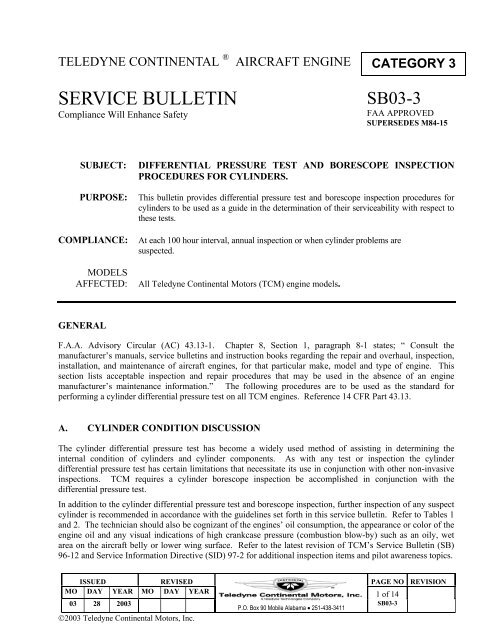
TELEDYNE CONTINENTAL ®<br />
AIRCRAFT ENGINE<br />
CATEGORY 3<br />
SERVICE BULLETIN<br />
Compliance Will Enhance Safety<br />
<strong>SB03</strong>-3<br />
FAA APPROVED<br />
SUPERSEDES M84-15<br />
SUBJECT:<br />
PURPOSE:<br />
COMPLIANCE:<br />
MODELS<br />
AFFECTED:<br />
DIFFERENTIAL PRESSURE TEST AND BORESCOPE INSPECTION<br />
PROCEDURES FOR CYLINDERS.<br />
This bulletin provides differential pressure test and borescope inspection procedures for<br />
cylinders to be used as a guide in the determination of their serviceability with respect to<br />
these tests.<br />
At each 100 hour interval, annual inspection or when cylinder problems are<br />
suspected.<br />
All Teledyne <strong>Continental</strong> <strong>Motors</strong> (TCM) engine models.<br />
GENERAL<br />
F.A.A. Advisory Circular (AC) 43.13-1. Chapter 8, Section 1, paragraph 8-1 states; “ Consult the<br />
manufacturer’s manuals, service bulletins and instruction books regarding the repair and overhaul, inspection,<br />
installation, and maintenance of aircraft engines, for that particular make, model and type of engine. This<br />
section lists acceptable inspection and repair procedures that may be used in the absence of an engine<br />
manufacturer’s maintenance information.” The following procedures are to be used as the standard for<br />
performing a cylinder differential pressure test on all TCM engines. Reference 14 CFR Part 43.13.<br />
A. CYLINDER CONDITION DISCUSSION<br />
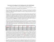
The cylinder differential pressure test has become a widely used method of assisting in determining the<br />
internal condition of cylinders and cylinder components. As with any test or inspection the cylinder<br />
differential pressure test has certain limitations that necessitate its use in conjunction with other non-invasive<br />
inspections. TCM requires a cylinder borescope inspection be accomplished in conjunction with the<br />
differential pressure test.<br />
In addition to the cylinder differential pressure test and borescope inspection, further inspection of any suspect<br />
cylinder is recommended in accordance with the guidelines set forth in this service bulletin. Refer to Tables 1<br />
and 2. The technician should also be cognizant of the engines’ oil consumption, the appearance or color of the<br />
engine oil and any visual indications of high crankcase pressure (combustion blow-by) such as an oily, wet<br />
area on the aircraft belly or lower wing surface. Refer to the latest revision of TCM’s Service Bulletin (SB)<br />
96-12 and Service Information Directive (SID) 97-2 for additional inspection items and pilot awareness topics.<br />
ISSUED REVISED PAGE NO REVISION<br />
MO DAY YEAR MO DAY YEAR 1 of 14<br />
03 28 2003<br />
©2003 Teledyne <strong>Continental</strong> <strong>Motors</strong>, Inc.<br />
P.O. Box 90 Mobile Alabama • 251-438-3411<br />
<strong>SB03</strong>-3
The purpose of the cylinder differential pressure test is to IDENTIFY LEAKS and the SOURCE OF LEAKS,<br />
with the engine under static conditions (not running), using a regulated pressure source. When performing a<br />
cylinder differential pressure test a regulated test pressure of eighty pounds per square inch (80 PSI) is directed<br />
into the cylinder with the piston at top dead center at the end of the compression stroke and the beginning of<br />
the power stroke. Eighty pounds per square inch (80 PSI) is used as a test pressure for safety reasons and is<br />
significantly less than the combustion pressure of 800 to 1000 PSI created during engine operation. Pistons,<br />
piston rings, valves and valve seats rely on combustion forces to assist in creating a complete seal during<br />
engine operation.<br />
NOTE: This static leak check does not relate directly to cylinder pressures developed during actual engine<br />
operations.<br />
The purpose of the cylinder borescope inspection is to provide a visual method of examining the internal<br />
cylinder components and must be used in conjunction with the differential pressure test.<br />
Excess cylinder wall or piston ring wear, broken piston rings and burned valves will normally be evidenced by<br />
additional conditions that must be taken into consideration when determining cylinder condition. These may<br />
include, but may not be limited to:<br />
Excessive cylinder barrel wear and/or piston ring wear:<br />
1. Elevated crankcase pressure; reference the latest revision of TCM Service Bulletin M89-9.<br />
2. Increased oil consumption. See note on page 9.<br />
3. Oil becoming discolored within first 10 hours after an oil change.<br />
4. High iron content in oil analysis may be an indication.<br />
Broken piston rings:<br />
1. Scored, grooved cylinder wall, evident via a borescope inspection.<br />
2. Abnormal debris in oil filter or oil screen.<br />
3. High iron content in oil analysis may be an indication.<br />
Burned Valves:<br />
1. Usually results in differential leak test reading in the 0/80 to 40/80 range.<br />
2. Easily identifiable during borescope inspection.<br />
Additionally, many variables affect what a technician sees from a differential pressure test reading. These<br />
variables include, but are not limited to:<br />
1. Abnormal amounts of oil in cylinder.<br />
2. Temperature of the engine and the uniformity of cylinder temperature at the time the differential<br />
pressure test is performed.<br />
3. Accuracy of the test equipment being used.<br />
4. Capacity and pressure output of the source of compressed air and the techniques used by the<br />
technician when performing the test.<br />
ISSUED REVISED PAGE NO REVISION<br />
MO DAY YEAR MO DAY YEAR 2 of 14<br />
03 28 2003<br />
P.O. Box 90 Mobile Alabama • 251-438-3411<br />
<strong>SB03</strong>-3
B. CYLINDER DIFFERENTIAL PRESSURE TEST:<br />
(a) Required Tools and Equipment:<br />
In addition to the standard complement of tools required to perform maintenance and repairs on aircraft<br />
engines the following tools and equipment are required to perform a cylinder differential pressure test.<br />
1. Source of dry, compressed air capable of providing a minimum line pressure of 125 P.S.I. with a minimum<br />
flow capability of 15 Cubic Feet per Minute.<br />
2. Cylinder differential pressure tester. Select one of the following units listed below or equivalent.<br />
• Eastern Technology Corporation Model E2M. See Figure 1. Recommended by TCM.<br />
This differential pressure tester incorporates the Master Orifice Tool.<br />
Eastern Technology Corporation<br />
180 Roberts Street<br />
East Hartford, CT 06108<br />
Phone: 860-528-9821<br />
• Eastern Technology Corporation Model E2A. See Figure 2.<br />
This differential pressure tester requires you to purchase separately the Master Orifice tool P/N<br />
646953.<br />
Eastern Technology Corporation<br />
180 Roberts Street<br />
East Hartford, CT 06108<br />
Phone: 860-528-9821<br />
3. Master Orifice Tool P/N 646953A.<br />
This tool is available in limited supply.<br />
SPX Corp. - Kent Moore Tool Division<br />
28635 Mound Road<br />
Warren, MI 48092<br />
Phone: 800-345-2233<br />
NOTE: Differential pressure test equipment must be certified and calibrated. Failure to properly maintain<br />
and calibrate test equipment may result in false cylinder differential compression readings.<br />
<br />
Eastern Technology Corporation offers calibration and repair service on these items.<br />
ISSUED REVISED PAGE NO REVISION<br />
MO DAY YEAR MO DAY YEAR 3 of 14<br />
03 28 2003<br />
P.O. Box 90 Mobile Alabama • 251-438-3411<br />
<strong>SB03</strong>-3
FIGURE 1<br />
Eastern Technology Corp. Model E2M<br />
FIGURE 2<br />
Eastern Technology Corp. Model E2A<br />
(b) Establishing the Acceptable Pressure Leakage Limit:<br />
The “Master Orifice” is a calibration standard that must be used prior to performing the cylinder<br />
differential pressure test. The “Master Orifice” establishes the Acceptable Cylinder Pressure Leakage<br />
Limit for the test equipment being used and the atmospheric conditions at the time of the test. The<br />
Acceptable Cylinder Pressure Leakage Limit reading must be recorded along with the individual cylinder<br />
readings in the engine logbook and the inspection work order.<br />
ISSUED REVISED PAGE NO REVISION<br />
MO DAY YEAR MO DAY YEAR 4 of 14<br />
03 28 2003<br />
P.O. Box 90 Mobile Alabama • 251-438-3411<br />
<strong>SB03</strong>-3
1) Eastern Technology Corporation Model E2M:<br />
This test is accomplished with no connections to the female quick connector.<br />
a) Set the Master Orifice Valve to the OFF position; handle horizontal and directly over<br />
the OFF label.<br />
b) Set the Slow Fill Valve (next to the pressure regulator) to the OFF position; handle<br />
vertical and pointing down.<br />
c) After making sure the Slow Fill Valve is OFF, connect your air source to the tester at<br />
the male quick connection fitting.<br />
d) Adjust pressure regulator so left hand gauge reads 80 PSI.<br />
e) Set the Master Orifice Valve to the TEST position; handle vertical and pointing<br />
down.<br />
f) Open the Slow Fill Valve completely; handle horizontal and over the<br />
PRESSURIZED label.<br />
g) If necessary, adjust the regulator to maintain 80PSI indication on the left-hand gauge.<br />
h) Record the pressure reading on the right hand gauge. This reading is the Minimum<br />
Acceptable Cylinder Pressure Leakage Limit.<br />
i) Close the Slow Fill Valve completely; handle vertical and pointing down.<br />
j) Set the Master Orifice Valve to the OFF position; handle horizontal and directly over<br />
the OFF label.<br />
You are now ready to perform the cylinder differential pressure test.<br />
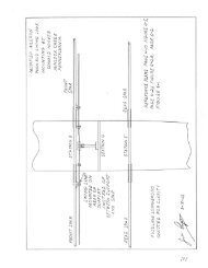
2) Standard Differential Pressure Tester and Master Orifice Tool P/N 646953:<br />
DUST CAP<br />
FACTORY CALIBRATED ORIFICE<br />
DUST CAP<br />
SPARK PLUG<br />
THREADS (18mm)<br />
FIGURE 3<br />
MASTER ORIFICE P/N 646953<br />
ISSUED REVISED PAGE NO REVISION<br />
MO DAY YEAR MO DAY YEAR 5 of 14<br />
03 28 2003<br />
P.O. Box 90 Mobile Alabama • 251-438-3411<br />
<strong>SB03</strong>-3
a) Make sure the Regulator Pressure Valve is backed all the way OUT.<br />
b) Make sure the Cylinder Pressure Valve is OFF or Closed.<br />
c) Remove the protective caps from both ends of the Master Orifice and install the<br />
Master Orifice onto the threaded end of the cylinder adapter and tighten hand tight.<br />
d) Connect the cylinder adapter with Master Orifice attached to the female quick<br />
connection on the supply hose from the differential test unit.<br />
e) Connect your air source to the tester at the male quick connection fitting.<br />
f) Adjust pressure regulator so regulator pressure gauge reads 80 PSI.<br />
g) Turn the cylinder pressure valve to the ON or OPEN position.<br />
h) If necessary, adjust the pressure regulator to maintain a reading of 80 PSI on the<br />
regulator pressure gauge.<br />
i) Record the pressure reading on the cylinder pressure gauge. This reading is the<br />
Minimum Acceptable Pressure Leakage Limit.<br />
j) Turn the cylinder pressure valve to the CLOSED or OFF position.<br />
k) Remove the cylinder adapter and Master Orifice from the female quick connection on<br />
the supply hose from the differential test unit.<br />
l) Remove the Master Orifice from the cylinder adapter.<br />
You are now ready to perform the cylinder differential pressure test.<br />
CYLINDER<br />
PRESSURE<br />
VALVE<br />
CYLINDER<br />
ADAPTER<br />
CYLINDER<br />
PRESSURE<br />
VALVE<br />
CYLINDER<br />
ADAPTER<br />
CYLINDER<br />
PRESSURE<br />
GAUGE<br />
CYLINDER<br />
PRESSURE<br />
GAUGE<br />
RESTRICTOR<br />
ORIFICE<br />
REGULATOR<br />
PRESSURE<br />
GAUGE<br />
MASTER ORIFICE<br />
(HAND TIGHT)<br />
RESTRICTOR<br />
ORIFICE<br />
REGULATOR<br />
PRESSURE<br />
GAUGE<br />
CYLINDER<br />
REGULATOR<br />
PRESSURE<br />
VALVE<br />
Read Minimum Acceptable Cylinder<br />
Leakage Limit on this Gauge<br />
REGULATOR<br />
PRESSURE<br />
VALVE<br />
Read Cylinder Leakage<br />
on this Gauge<br />
COMPRESSED<br />
AIR SOURCE<br />
COMPRESSED<br />
AIR SOURCE<br />
Establishing Minimum Acceptable<br />
Cylinder Pressure Leakage Limit With<br />
Master Orifice Tool<br />
FIGURE 3<br />
FIGURE 4<br />
Differential Pressure Test Equipment<br />
Performing Differential Pressure Test<br />
ISSUED REVISED PAGE NO REVISION<br />
MO DAY YEAR MO DAY YEAR 6 of 14<br />
03 28 2003<br />
P.O. Box 90 Mobile Alabama • 251-438-3411<br />
<strong>SB03</strong>-3
(c) Performing The Cylinder Differential Pressure Test:<br />
Ideally, perform the cylinder differential pressure test as soon as possible after the aircraft has been flown.<br />
If the aircraft cannot be flown prior to performing the cylinder differential pressure test, it must be<br />
operated on the ground, with the cowling installed until a minimum cylinder head temperature (CHT) of<br />
300 to 350 degrees Fahrenheit is observed on the aircraft gauge. For aircraft fitted with constant speed<br />
propellers operate the engine at a high enough power setting to allow the cycling of the aircraft propeller.<br />
For aircraft with fixed pitched propeller, operate the engine to full static RPM.<br />
WARNING<br />
Magnetos must be grounded and fuel must be shut off prior to test to make certain that the<br />
engine cannot accidentally start. Take necessary precautions to prevent accidental rotation<br />
of the propeller while performing the differential pressure leak test. Differential Pressure<br />
tests are best performed with two people, one to adjust the pressure regulator and one to<br />
hold the aircraft propeller.<br />
NOTE:<br />
The 360 series, 470 series and 520/550 Sandcast engines utilize a starter adapter design that<br />
results in an increased resistance in turning force when the propeller is turned in the opposite<br />
direction of normal rotation. The technician may, if he desires, reduce the amount of<br />
resistance by removing the starter motor from the starter adapter when performing this test.<br />
1. Perform the test as soon as possible after the engine is shut down to ensure that the piston rings,<br />
cylinder walls, and other engine parts are well lubricated and at operating clearance.<br />
2. Remove the most accessible spark plug from each cylinder. Identify the cylinder number and<br />
position of the removed spark plugs. Examination of the spark plugs will aid in diagnosing engine<br />
and cylinder conditions. Reference spark plug manufacturers’ technical data.<br />
3. Turn the crankshaft by hand in the direction of rotation until the piston (in the cylinder being<br />
checked) is coming up on its compression stroke.<br />
4. Install the cylinder adapter in the spark plug hole and connect the differential pressure tester to the<br />
adapter. (NOTE: Cylinder pressure valve is in the CLOSED position). Slowly open the cylinder<br />
pressure valve and pressurize the cylinder to 20 PSI.<br />
5. Continue rotating the engine in the normal direction of rotation, against this pressure, until the piston<br />
reaches top dead center (TDC). TDC is indicated by a sudden decrease in the force required to turn<br />
the crankshaft. If the crankshaft is rotated too far, back up at least one-half revolution and start over<br />
again to eliminate the effect of backlash in the valve operating mechanism and to keep the piston<br />
rings seated on the piston ring lands.<br />
WARNING<br />
Care must be exercised in opening the cylinder pressure valve, since sufficient air<br />
pressure will be built up in the cylinder to cause it to rotate the crankshaft if the piston<br />
is not at TDC.<br />
6. With the piston at top dead center, open the cylinder pressure valve completely. Check the<br />
regulator pressure gauge and adjust, if necessary, to 80 PSI.<br />
7. To assure that the piston rings are seated and the piston is square in the cylinder bore, move the<br />
propeller slightly back and forth with a rocking motion, while applying the regulated pressure of 80<br />
PSI, to obtain the highest indication. Adjust the regulator as necessary to maintain a pressure gauge<br />
reading of 80 PSI.<br />
ISSUED REVISED PAGE NO REVISION<br />
MO DAY YEAR MO DAY YEAR 7 of 14<br />
03 28 2003<br />
P.O. Box 90 Mobile Alabama • 251-438-3411<br />
<strong>SB03</strong>-3
8. Record the pressure indication on the cylinder pressure gauge. The difference between this pressure<br />
and the pressure shown by the regulator pressure gauge is the amount of leakage through the cylinder.<br />
Record individual cylinder readings as; (pressure reading) / 80 PSI .<br />
9. Note any leakage source (air discharge) and determine serviceability. Refer to Table 1.<br />
10. Proceed to the next cylinder and repeat Step 3 through 9 until all cylinders have been checked.<br />
11. After all cylinder pressure indications have been recorded, proceed with a borescope inspection of<br />
each cylinder in accordance with Table 2, section C.<br />
AIR DISCHARGE<br />
SOURCE<br />
Air discharge at oil<br />
filler/crankcase breather.<br />
Air discharge at oil<br />
filler/crankcase breather.<br />
TABLE 1<br />
DIFFERENTIAL PRESSURE TEST RESULTS<br />
PRESSURE TEST VALUE SYMPTIONS AND<br />
OBSERVATIONS<br />
Cylinder differential pressure Normal Borescope Indications.<br />
test reading above leakage Oil Consumption stable, no<br />
limit.<br />
excessive oil discharge out<br />
engine breather.<br />
Cylinder differential pressure<br />
test reading below leakage<br />
limit.<br />
Cylinder differential pressure<br />
test reading below leakage<br />
limit after re-check<br />
Cylinder differential pressure<br />
test reading above or below<br />
leakage limit.<br />
Normal Borescope Indications.<br />
Oil Consumption stable, no<br />
excessive oil discharge out<br />
engine breather.<br />
N/A<br />
Oil Consumption abnormal ,<br />
with oil discharge out engine<br />
breather.<br />
Borescope inspection reveals<br />
heavy carbon deposits in<br />
combustion chamber and on<br />
piston crown with<br />
excessive oil puddling in<br />
cylinder barrel<br />
RECOMMENDED ACTION<br />
Continue engine in service.<br />
Repeat differential pressure<br />
test at next 100-hour/annual<br />
inspection.<br />
Fly Aircraft at Cruise Power<br />
setting and repeat cylinder<br />
differential pressure test<br />
Remove cylinder for repair<br />
Remove cylinder for repair<br />
ISSUED REVISED PAGE NO REVISION<br />
MO DAY YEAR MO DAY YEAR 8 of 14<br />
03 28 2003<br />
P.O. Box 90 Mobile Alabama • 251-438-3411<br />
<strong>SB03</strong>-3
AIR DISCHARGE<br />
SOURCE<br />
Little to no air discharge at<br />
oil filler/crankcase breather.<br />
TABLE 1 (continued)<br />
DIFFERENTIAL PRESSURE TEST RESULTS<br />
PRESSURE TEST VALUE SYMPTIONS AND<br />
OBSERVATIONS<br />
Oil Consumption abnormal <br />
with oil discharge out engine<br />
Cylinder differential pressure breather.<br />
test reading abnormally high Borescope inspection reveals<br />
heavy carbon deposits in<br />
combustion chamber and on<br />
piston crown.<br />
Excessive oil puddling in<br />
cylinder barrel.<br />
Cylinder differential pressure<br />
test reading above leakage<br />
limit.<br />
Normal cylinder borescope<br />
inspection results.<br />
RECOMMENDED ACTION<br />
Remove cylinder for repair.<br />
Continue engine in service.<br />
Air discharge into induction<br />
system<br />
Cylinder differential pressure<br />
test reading below leakage<br />
limit.<br />
Normal cylinder borescope<br />
inspection results.<br />
Fly aircraft at cruise power <br />
and repeat cylinder differential<br />
pressure test.<br />
Cylinder differential pressure<br />
test reading below leakage<br />
limit after re-check.<br />
N/A<br />
Remove cylinder for repair.<br />
Cylinder differential pressure<br />
test reading above leakage<br />
limit.<br />
Normal cylinder borescope<br />
inspection results.<br />
Continue engine in service.<br />
Air discharge into exhaust<br />
system<br />
Cylinder differential pressure<br />
test reading below leakage<br />
limit.<br />
Normal cylinder borescope<br />
inspection results.<br />
Fly aircraft at cruise power <br />
and repeat cylinder differential<br />
pressure test.<br />
Air escaping at spark plug<br />
spot face<br />
Air discharge at cylinder<br />
head to barrel juncture or<br />
between barrel fins<br />
Cylinder differential pressure<br />
test reading below leakage<br />
limit after re-check.<br />
Cylinder differential pressure<br />
test readings N/A<br />
Cylinder differential pressure<br />
test readings above leakage<br />
limit<br />
N/A<br />
Dye check of area reveals<br />
cracks.<br />
First cylinder head fin above<br />
cylinder barrel wet with oil or<br />
baked on oil residue. See also<br />
latest revision of SB96-12 for<br />
additional test to be performed.<br />
Remove cylinder for repair<br />
Remove cylinder for<br />
replacement.<br />
Remove cylinder for<br />
replacement.<br />
Fly the aircraft at a cruise power setting between 65 and 75 percent power, as specified in the<br />
aircraft Pilots Operating Handbook/Aircraft Flight Manual (POH/AFM), for a duration that<br />
will allow the engine oil and cylinder head temperatures to stabilize, or at least 45 minutes.<br />
Perform an additional differential compression test on the suspect cylinder(s).<br />
A sudden increase in oil consumption from the established or normal trend for the engine or<br />
an oil consumption rate that exceeds 1/2 quart (liter) per hour during normal engine<br />
operation.<br />
ISSUED REVISED PAGE NO REVISION<br />
MO DAY YEAR MO DAY YEAR 9 of 14<br />
03 28 2003<br />
P.O. Box 90 Mobile Alabama • 251-438-3411<br />
<strong>SB03</strong>-3
C. CYLINDER BORESCOPE INSPECTION<br />
(a) Required Equipment:<br />
In addition to the standard complement of tools required to perform maintenance and repairs on aircraft<br />
engines the following tools and equipment are required to perform a cylinder borescope inspection.<br />
1. Borescope.<br />
• AUTOSCOPE TM – Lenox Instrument Company. See Figure 5. Recommended by TCM.<br />
Q. A. Technologies<br />
PO Box 61085<br />
Savannah, GA 31420<br />
Phone: 912-330-0500<br />
Fax: 912-330-0104<br />
E-mail: sales@qatek.com<br />
Web-site: qatek.com<br />
Note: TCM customers receive a special discount when ordering from Q. A. Technologies.<br />
FIGURE 5<br />
(b) Performing the Inspection:<br />
CAUTION<br />
Take preventative measures to avoid burns when performing a borescope inspection on a hot engine.<br />
1. If not already removed for differential pressure test, remove the upper spark plug from each cylinder.<br />
2. Position piston at bottom dead center on the power stroke. The exhaust valve will be open with the<br />
piston in this position.<br />
3. Insert the borescope probe through the upper spark plug hole and inspect the internal surfaces of each<br />
cylinder, including the exhaust valve and exhaust valve seat in accordance with Table 2.<br />
4. After completing inspection steps 1,2 and 3; position piston at bottom dead center at the end of the<br />
intake stroke.<br />
5. Insert the borescope probe through the upper spark plug hole and inspect the intake valve and intake<br />
valve seat in accordance with Table 2.<br />
ISSUED REVISED PAGE NO REVISION<br />
MO DAY YEAR MO DAY YEAR 10 of 14<br />
03 28 2003<br />
P.O. Box 90 Mobile Alabama • 251-438-3411<br />
<strong>SB03</strong>-3
TABLE 2<br />
Borescope Inspection Objectives And Corrective Actions<br />
ITEM Objective If Abnormality Noted<br />
Combustion<br />
chamber.<br />
Inspect:<br />
1. Valve seat inserts for erosion, burning.<br />
2. Sparkplug heli-coils for protrusion into combustion<br />
chamber.<br />
3. Heavy carbon deposits/presence of excessive oil.<br />
1. Remove cylinder for repair<br />
2. Remove cylinder for repair<br />
3. Remove cylinder for repair.<br />
Exhaust valve face<br />
Intake valve face.<br />
Cylinder Bore.<br />
Piston Head.<br />
Inspect for signs of leakage or damage, indicated by:<br />
1. Localized discoloration on the valve face circumference.<br />
See Figure 7 page 12<br />
2. Minute cracks.<br />
3. Erosion (missing material).<br />
Inspect for signs of leakage or damage, indicated by:<br />
1. Localized discoloration on the valve face circumference.<br />
2. Erosion (missing material)<br />
Inspect exposed surface of bore for:<br />
1. Heavy scoring/piston rub. See Figure 10 on page 13.<br />
2. Piston pin rub (wide ban pattern in horizontal plane at 3<br />
o’clock and/or 9 o’clock position).<br />
3. Upper portion of cylinder bore has no visible hone<br />
pattern. See Figure 11 &12 on page 13 and 14.<br />
4. Corrosion. See Figure 9, on page 12.<br />
5. Excessive oil in cylinder/heavy deposits of carbon in<br />
combustion chamber<br />
Inspect for:<br />
1. Piston crown for erosion, missing material<br />
2. Visible damage from foreign debris.<br />
1. Repair or replace cylinder.<br />
2. Repair or replace cylinder.<br />
3. Repair or replace cylinder.<br />
1. Repair or replace cylinder.<br />
2. Repair or replace cylinder.<br />
1. Repair or replace cylinder.<br />
2. <br />
3. Normal indication for in<br />
service cylinders<br />
4. <br />
5. Remove cylinder for repair<br />
1. Remove cylinder for repair<br />
2. Remove cylinder for repair<br />
Experience and expertise in borescope examination requires the aviation technician to perform borescope<br />
inspection on a consistent basis. It is especially important that the technician perform borescope<br />
inspections prior to removal of a cylinder for any reason so that they may validate by visual indications<br />
viewed through the borescope, the actual conditions.<br />
The following photographs are provided as a guide to the aviation technician when performing borescope<br />
examinations. Teledyne <strong>Continental</strong> <strong>Motors</strong> welcomes inquiries and comments from the aviation<br />
technician. We urge you to call your Regional Service Representative or Teledyne <strong>Continental</strong> <strong>Motors</strong><br />
Technical Support at (888) 826-5465.<br />
Remove cylinder for repair or replacement. Perform complete inspection of connecting rod<br />
bushing for correct installation and finishing. Refer to latest revision of TCM SB 00-3.<br />
Refer to the latest revision of TCM Service Information Directive (SID) 97-2. See Figure 9.<br />
ISSUED REVISED PAGE NO REVISION<br />
MO DAY YEAR MO DAY YEAR 11 of 14<br />
03 28 2003<br />
P.O. Box 90 Mobile Alabama • 251-438-3411<br />
<strong>SB03</strong>-3
Normal Combustion Chamber. Exhaust<br />
valve has reddish combustion deposit in<br />
center with dark outer edge. Intake valve<br />
has light brown combustion deposits.<br />
Combustion chamber has light brown<br />
deposits.<br />
Burned exhaust valve. Note edge of<br />
valve face that has lost all combustion<br />
residue and striations moving toward<br />
center of valve.<br />
FIGURE 6 FIGURE 7<br />
New Phosphate coated cylinder bore with<br />
revised cylinder bore hone pattern. Phosphate<br />
coating provides increase corrosion protection<br />
during the initial hours of engine operation.<br />
Phosphated cylinder bore. Note phosphate<br />
coating remaining in valleys of cylinder bore hone<br />
pattern. Light corrosion at top of cylinder bore,<br />
above piston ring travel limit. Presence of light<br />
corrosion in this area is normal.<br />
FIGURE 8 FIGURE 9<br />
ISSUED REVISED PAGE NO REVISION<br />
MO DAY YEAR MO DAY YEAR 12 of 14<br />
03 28 2003<br />
P.O. Box 90 Mobile Alabama • 251-438-3411<br />
<strong>SB03</strong>-3
FIGURE 10<br />
CYLINDER BARREL SCORING / PISTON RUB<br />
FIGURE 11<br />
UPPER RING TRAVEL AREA<br />
TYPICAL IN SERVICE CYLINDER BARREL<br />
ISSUED REVISED PAGE NO REVISION<br />
MO DAY YEAR MO DAY YEAR 13 of 14<br />
03 28 2003<br />
P.O. Box 90 Mobile Alabama • 251-438-3411<br />
<strong>SB03</strong>-3
FIGURE 12<br />
TYPICAL IN SERVICE CYLINDER BARREL<br />
ISSUED REVISED PAGE NO REVISION<br />
MO DAY YEAR MO DAY YEAR 14 of 14<br />
03 28 2003<br />
P.O. Box 90 Mobile Alabama • 251-438-3411<br />
<strong>SB03</strong>-3