Intercylinder Baffles - The Fly Baby Home Page
Intercylinder Baffles - The Fly Baby Home Page
Intercylinder Baffles - The Fly Baby Home Page

You also want an ePaper? Increase the reach of your titles
YUMPU automatically turns print PDFs into web optimized ePapers that Google loves.
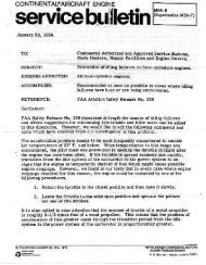
Continental C-85/C-90/O-200 Engine <strong>Intercylinder</strong> <strong>Baffles</strong><br />
and Oil Tank Baffle<br />
Cessna 120/140/140A<br />
Purpose and History:<br />
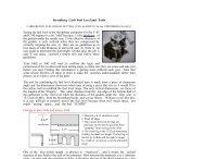
Any cooling air that is not forced to contact a cylinder fin as it flows past is wasted energy and wasted<br />
cooling. <strong>The</strong> purpose of the intercylinder baffles is to guide the air, force it to contact the fins, and not<br />
allow it to escape unused between the cylinders. <strong>The</strong>se simple sheet metal intercylinder baffles used for all<br />
our engines are seldom noticed or spoken about but they are very important for good engine cooling. Over<br />
the years, Cessna has made few changes to them, and only one change, initially optional, is noticeable in<br />
the older parts manuals, but in the later manuals it is absorbed into the assemblies such that it is not<br />
treated as special or optional, just necessary. A lot of the high temperature problems are due to poor<br />
baffling, and the experts state that even small openings make significant changes in the local temperatures.<br />
To equalize cooling and keep the temperatures as low as possible, the often-overlooked intercylinder baffles<br />
need some attention at annual time, too. <strong>The</strong>y wear from vibration, many still have not had the<br />
recommended extension added, and the music wire and springs used for retaining them often succumbs to<br />
rust. Some who read this will find that the bottom baffles shown here are missing.<br />
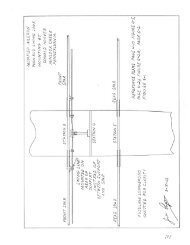
<strong>The</strong> intercylinder features Cessna forgot to include in the manual become easier to understand when looking<br />
at the sketches above. 1. Bare. 2. Top side, outboard baffle only. 3. Top side, both baffles without the<br />
later extension. 4. Bottom side, both baffles, with the longer tail on the inboard set to the rear. 5. Both<br />
baffles from the top, including the extension added by the service bulletin to the inner baffle.<br />
Whether inner or outer baffling, the setup is similar: A) the retainer at the<br />
top side rests on the walls of the cylinder, B) the music wire is formed to<br />
support the spring at the bottom and connect to the top retainer, C) the spring<br />
which provides force to keep the pieces in position against the pressure of the<br />
airflow, D) the baffle itself, and E) the washers which serve to lock the<br />
music wire and act as sacrificial buffers at the top and bottom.<br />
<strong>The</strong> topside retainer is made up of thicker aluminum<br />
than the baffles, with dimensions chosen to fit between<br />
the cylinders, resting the curved portions of the retainer on the cylinders. <strong>The</strong> hole is<br />
slightly below the center point and is made large enough for the music wire to go<br />
through. <strong>The</strong> curves indicated should be formed so as to fit against the matching<br />
curvature of the cylinders.<br />
<strong>The</strong> next piece in the stack is the formed music wire, starting with lengths of 8 or ten inches because<br />
some of the length will be used as a “handle” when forming the loop. Cutting music wire is unique because<br />
the material is so hard it will damage almost every type of shear cutter made. Please don’t try to prove me<br />
wrong because your cutters will suffer. <strong>The</strong> best way to cut it is to retain a length of it in a vise. Take a<br />
fine-toothed triangular file or the corner of a fine toothed file and make a gouge in the wire as close as<br />
possible to the vise jaws. It will take several cycles of the file to make<br />
the gouge. Next, with safety glasses on (the music wire is brittle and<br />
tends to expel extremely sharp shards when broken), break the wire. If<br />
you made the gouge while holding the wire in the vise, slide the wire<br />
so that the gouge is as close as possible to the vise jaws, and then take<br />
a pair of pliers, position them as close as possible to the gouge and<br />
bend to break.
If you have no vise, take two pairs of pliers and place their jaws as close to the gouge as possible and twist<br />
away from each other, expecting the wire to fracture at the gouge with only one or two twists. <strong>The</strong> ends<br />
will be unbelievably sharp and have a tendency to “jump” into fingers. If possible, round the ends with a<br />
fine sander or on a piece of sandpaper.<br />
Form the bottom end loop first. To apply the compression force of the spring, we have to slightly<br />
compress it and that is done by forcing the loop of the music wire against the spring bottom. <strong>The</strong> loop<br />
has to be larger than the diameter of the spring so it does not get pulled through. <strong>The</strong> loop is best formed<br />
around a mandrel which can be made of anything round or square about 3/8ths of an inch in its<br />
major dimension. With the mandrel in a vise, hold one end of the wire with the pliers about an<br />
inch from the mandrel and pull the other end tightly around the mandrel to make a loop and a<br />
half. As soon as you let go, it will spring back somewhat. If done properly, you will end up<br />
with slightly more than a full loop and the loop will be larger than the diameter of the mandrel.<br />
Put the loop in the vise and shape it as shown, and then tie off the end with one or two complete<br />
loops around the vertical portion or wound around to form half a knot. Remove the excess music<br />
wire.<br />
<strong>The</strong> top half loop is shown formed here as well but it will actually be made at the time you fit<br />
things together at the plane so as to adjust tension. It is a half loop made at the time of installation so as<br />
to provide some spring compression against the baffle. You will make the half loop at the plane with pliers<br />
and the amount of tail is not critical but have the file and plier sets there to trim if you desire.<br />
<strong>The</strong> spring, steel washers, and music wire form a subassembly such as this and the assemblies look like the<br />
next figures. <strong>The</strong> washers ensure that the loop at the bottom does not pull through the spring, and both<br />
washers serve as the sacrificial items because the vibration and pressures will otherwise let the spring wear<br />
through the baffle.<br />
Outboard baffles:<br />
<strong>The</strong> outboard baffle dimensions are about as noted,<br />
with the top formed over a mandrel of wood held<br />
in the vise. With light tapping on the top and on<br />
the corners, a flat top surface and nicely rounded<br />
corners will result. <strong>The</strong> exact shape at the top is<br />
not important except it must fit between the fins<br />
of the cylinders and that dimension is actually less<br />
than your recollection will suggest. After<br />
forming, drill or punch the hole in the middle of<br />
the new spine to a diameter of about 1/8th inch. If<br />
you are good at keeping things aligned, the hole<br />
can be drilled first and used with a screw to keep<br />
the unformed piece in place on the mandrel while<br />
you do the forming.<br />
2
<strong>The</strong> “wings” of the baffle can be partially shaped on the bench if you wish, by hand, but the final shaping<br />
will take place at the engine, fitting it by hand to mate closely to the fins. After you have formed the final<br />
shape, you also have the option of using pliers to bend the edges so as to strengthen the baffle but this step<br />
does not seem necessary, based on those non-stiffened baffles observed after long service.<br />
<strong>The</strong> fabricator should avoid the temptation to make the baffles “longer or wider”,<br />
because you will create a conflict; longer means the extra material will strike<br />
the pushrod tube such that you won’t be able to install the baffle and will have<br />
to trim it at the plane. Take the sheet metal cutter and a file along to the plane<br />
just in case because something always seems to need a trim.<br />
Inboard <strong>Baffles</strong>:<br />
<strong>The</strong> inboard baffle pieces are larger because the inboard cylinder fins are shorter and the base diameters of the<br />
inner portion of the cylinders are smaller. <strong>The</strong> dimensions of the pieces are about as noted for the retainer<br />
and the baffle. <strong>The</strong> longer tail goes to the rear of the engine. Do not add to the dimensions in the interest<br />
of making them do “better”, because the extra material will interfere with the outer cylinder fin or the outer<br />
baffle or the bolts which hold the cylinders to the block. You will be surprised how many things are<br />
waiting to interfere if you change the dimensions to “make them better”. It will seem odd that the top<br />
retainer is bigger for the inner baffle but it will make sense when you see the later sketches.<br />
4"<br />
2-7/8<br />
1"<br />
5/8<br />
4"<br />
3<br />
As a “summerization” kit, the odd space inboard of the original inboard baffle<br />
(shown in green in this small sketch) was to be filled in with a tab; for later<br />
manufacture, the tabs were made standard for the inboard baffles. It seems to be<br />
a good idea to incorporate the tabs whatever the status of your baffles. <strong>The</strong><br />
approximate dimensions are as shown and you need to take the sheet metal<br />
cutters and file to the plane when fitting this baffle set as well. Although the tab was<br />
initially attached with screws (it started as part of the "summerization kit so could be removed) and nuts of<br />
some sort, many later units were attached with rivets and left on year round.<br />
3
1.3<br />
0450321<br />
0.85<br />
1/8th<br />
Rivet,<br />
Typical<br />
2 plcs<br />
1.1<br />
0.58<br />
1.0<br />
0.62<br />
0.62<br />
<strong>The</strong> Cessna part number for the tab is noted on the sketch. In order for the baffle with this tab attached to<br />
fit in the space, the ears must be bent as noted and no two seem to be the same so plan on “fitting as<br />
required”. This sketch is nearly to scale as I have drawn it so that readers could use it as a pattern but make<br />
sure your computer/printer combination did not seriously change its dimensions.<br />
<strong>The</strong> baffle for the left is on the left and that for the right is on the right, long tail to the rear in both cases.<br />
When installing the replacement topside retainers, the “assumed” curved cutouts made at home did not work<br />
at all so these sketches are made with the intent to guide you to avoid what I did. <strong>The</strong>se curves and distances<br />
between approximate the cylinders and some study will indicate to you that the outboard fins are closer than<br />
memory would have put them, and that is why the top side flat of the outboard baffles have to be formed<br />
over a quarter inch thick mandrel. <strong>The</strong> second and third sets show you why the width of the topside<br />
retainers so drastically affect the matching curves of the retainers, and how (note the middle set with the red<br />
retainers) the baffle will pull up against the retainer before there is any compression of the spring if you<br />
choose a top retainer which is too narrow. <strong>The</strong> other point in matching the curves as well as possible is to<br />
avoid having such a poor contact between the top retainers and the curves of the cylinders that fretting from<br />
a sharp point of the retainers will induce a depression in the very expensive cylinder walls.<br />
From the parts list manual, the intercylinder baffles are items 4X of figure 37 on page 71 for the ‘46 planes<br />
and items 5X in Figure 38 for the ‘47/’48 planes.<br />
<strong>The</strong> curves on the next page approximate the big fins of the outer portions of the cylinders and the inner<br />
diameters as well. To provide clarity, the fourth curve of the fin/cylinders is not indicated. When printed,<br />
the size of the simulated cylinder circles is close to reality, so you can use them to roughly gauge how big<br />
or small you want your hangars to be.<br />
4
<strong>The</strong> figures below are not to scale, but are here to illustrate how the width of the hangars make such a large<br />
effect with respect to how long/short the spring needs to be to attach to the baffles.<br />
5
Material:<br />
Whether inner or outer, the baffling is usually made up of 0.025 aluminum, and making a set is relatively<br />
easy without special tools since the curving of the pieces can be done by hand. Compression springs from<br />
many sources are usable, and music wire is available from most hardware stores.<br />
Aluminum sheet, 0.025 for the baffling and 0.040 or 0.050 for the topside retainers.<br />
Music wire, about 0.040 diameter.<br />
Springs.<br />
Washers.<br />
Rivets or screws/washers<br />
Tools:<br />
Sheet metal cutters.<br />
Vise<br />
Mandrel for shaping the music wire<br />
Pliers, two sets, for breaking the music wire and manipulating it<br />
Drill and bits for the holes in the retainers and the rivet holes.<br />
Rivets, soft or sheet metal screws and Tinnerman nuts as the picture from<br />
Sandpaper<br />
the manual shows<br />
Finally:<br />
Use a file or the sandpaper to break the edges of the sheet metal pieces because manipulating them while<br />
making them fit to the engine will otherwise cause cuts.<br />
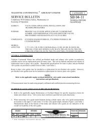
This shows the figure 77<br />
with the "summerization kit<br />
addition, item 1, 2, and 3.<br />
Most who add the extender of the winterization kit install it with rivets and leave it in; the 140A figure<br />
shows it permanently attached. This figure indicates screws and Tinnerman nuts for a temporary<br />
attachment. I have yet to see one installed with the screws.<br />
6
Oil Tank Baffle and <strong>Intercylinder</strong> arrays:<br />
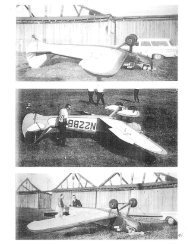
<strong>The</strong> oil tank baffle is supposed to be on all the 120/140’s all year round; the 140A parts manual does not<br />
show one. Following, the three versions of the intercylinder array; note that the 140A view shows the<br />
springs and piano wire hangers and permanently fixed (red) extender for the first time.<br />
'46 <strong>Intercylinder</strong> baffles and oil tank baffle on the<br />
left, with like items on the right from the '47/'48<br />
140A array<br />
Concerning the 120/140’s, item 45 of page 71 and item 36 on page 75 show the oil tank baffle for all the<br />
of the planes through ‘48. Note that there is no coding which suggests that it is a part to be taken off in<br />
the summer and put back on in the winter.<br />
<strong>The</strong> intent of the baffle in front of the oil tank is this: the air forced into the two oval-shaped openings in<br />
the front of the cowling below the crankshaft opening travels along the channel formed by the engine and<br />
the sheet metal tray (items 47 and 49 of figure 37). <strong>The</strong> cooling air is routed past the case where the oil<br />
galleries (yes, galleries, not galleys) are, removing heat from the case which encloses them and then that<br />
cooling air stream is forced between the oil tank baffle and the oil tank, assisting in reducing the oil<br />
temperature of the oil in the tank.<br />
7
'46 Tray '47/'48 Tray<br />
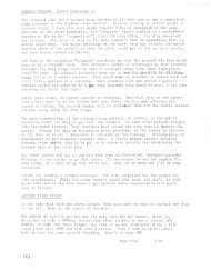
One of the hardest to kill old wives’ tales is that promoted so strongly over the years which nobody dared<br />
defy, stated pontifically by the mechanic during annuals: “the oil tank baffle is A) ineffective and therefore<br />
should be removed, or B) its a winterization thing and you don’t need it in this weather so I took it off<br />
without asking you because I, the A&X, KNOW”. But they (or you) never looked up or confirmed whether<br />
it was true, so off they came, to the hot oil owner’s detriment. Back in the days when I let the FBO’s<br />
experts do all of the annuals, one of them took it off, handed me the baffle, and then put it back on after<br />
being shown that it should be there.<br />
Go to page 64 of the parts manual and note the “winterization” kit.<br />
<strong>The</strong> oval inlet ports are plugged so no cooling air goes past the<br />
galleries or between the oil tank baffle and the oil tank. An important<br />
part of the kit is the asbestos (back then it was) blanket which goes<br />
over the oil tank.<br />
<strong>The</strong> oil tank baffle is neither a summerization kit part nor a<br />
winterization kit part...it is supposed to be on the engine all the time.<br />
Neal<br />
Plugs for the oval<br />
openings, part of the<br />
winterization kit.<br />
Oval-shaped<br />
Cold air inlets<br />
Trough<br />
Screws<br />
Nutplates<br />
Not all attachment points are<br />
shown.<br />
Attach to airbox<br />
This figure is a simple diagram showing the oval-shaped cold air inlets on the left, and the sheet metal<br />
trough which guides the cold air past the case with the oil galleries and the oil tank baffle and oil tank. <strong>The</strong><br />
next figures show the intended flow.<br />
8
Green...airflow<br />
<strong>The</strong> figure above suggests the intended the air flow which directs and controls the airflow around the oil<br />
tank...for clarity, I have shown just the center curvature of the baffle.<br />
Green...airflow<br />
In the view above, a truer view of the intended cold air flow past the oil tank. I can't indicate in 3D that<br />
the air tends to "stick" to the curved surface of the tank so that some of the air curves around the sides and a<br />
slightly around the back before it breaks away.<br />
TOP View<br />
Front view of the baffle on the left, rear view in the center (the Florida-shaped cutout is for the throttle<br />
cable, and the round hole is for the carb heat cable) and the top view on the right. Between the views, you<br />
can see the five attach points.<br />
Filed as: <strong>Intercylinder</strong>/ OilTank <strong>Baffles</strong> Revised 8 June 2003 cougarnfw@aol.com<br />
Neal F. Wright<br />
1542 South Wolfe Rd.<br />
Sunnyvale CA 94087<br />
9