
You also want an ePaper? Increase the reach of your titles
YUMPU automatically turns print PDFs into web optimized ePapers that Google loves.
50 th Anniversary Edition edited by Ron Wanttaja
WELCOME to the world-wide family of FLY BABY builders.<br />
THIS IS THE 10th printing of the plans document, from which nearly 300 examples have been<br />
completed and flown in the United States and several foreign countries to this date.<br />
<strong>The</strong> first printing was in February, 1963, and succeeding editions have incorporated minor<br />
corrections and clarifications to the plans as they have been pointed out by the readers.<br />
Photographs of individual variations have been added, along with reprints of SPORT AVIATION<br />
articles, to give potential builders the benefit of others’ experience with their FLY BABIES.<br />
Further safety information was added by pages 8-32 and 8-33 to the Ninth Edition in 1982 and<br />
has been revised for this edition.<br />
In all of these years, there has been no evidence of structural short-comings in the design or a<br />
need to publish “fixes” to correct unsafe conditions. <strong>The</strong> recommendation for the rear spar carrythrough<br />
reinforcement on <strong>Page</strong> 9-9 is just that - not a requirement. <strong>The</strong> original FLY BABY has<br />
flown over 1400 hours since 1960 without it.<br />
Accidents and their causes are discussed in the SPORT AVIATION reprint starting on <strong>Page</strong> 8-29,<br />
but one more should be mentioned. A new owner bought a used and out-of-license FLY BABY and<br />
had a wing come off in level flight. It turns out that the airplane had been tied outside for a couple<br />
of winters in Florida. Trapped water in the fuselage rotted out some of the lower structure to the<br />
point where the rear spar pins pulled out of the spar carry-through under load. <strong>The</strong> new owner<br />
had not even inspected the long-unused airplane for condition before flying it. Further, nothing is<br />
known of the adequacy of the original varnish applications or the bottom drains that are specified<br />
in the plans for the specific purpose of avoiding water damage.<br />
This unfortunate event is mentioned here only to emphasize the importance of vigilant<br />
maintenance to any airplane, homebuilt or otherwise, and the need to keep it in good condition -<br />
and legal.<br />
Peter M. Bowers<br />
Seattle, Washington<br />
January 1, 1985<br />
B
Introduction to the 50 th Anniversary Edition<br />
Fifty years ago, a Seattle engineer/author designed and built a pretty good airplane.<br />
It wasn’t fast.<br />
It wasn’t fancy.<br />
It couldn’t haul the entire family.<br />
It couldn’t perform eight-point rolls on takeoff.<br />
About the only thing it DOES do is leave a grin on the face of just about anyone who flies it.<br />
Pete Bowers generously let EAA Chapter 26 form a flying club around the original <strong>Fly</strong> <strong>Baby</strong> back it<br />
the mid-1980s. I remember my first flight in N500F like it was yesterday. I remember breaking<br />
ground, and laughing from the sheer joy of flying that little beauty.<br />
I flew N500F in the club for about seven years. When Pete decided to sell the airplane, I bought<br />
half-interest in a 1947 Stinson.<br />
<strong>The</strong> Stinson was a great airplane. But it wasn’t a <strong>Fly</strong> <strong>Baby</strong>.<br />
After a year and a half of partnership, a very nice local <strong>Fly</strong> <strong>Baby</strong> came up for sale. After talking<br />
with my Stinson partner, I sold him my half-interest and bought the <strong>Fly</strong> <strong>Baby</strong>. Other than that<br />
dalliance with the Stinson and the occasional Biannual Flight Review in a rented airplane, I’ve<br />
flown <strong>Fly</strong> Babies almost exclusively for the past 25 years.<br />
Health willing, I hope to fly them for the next 25 years as well.<br />
I take my <strong>Fly</strong> <strong>Baby</strong> to fly-ins a lot. One of the most common comments I hear is, “I used to own<br />
one of these a long time ago. I wish I still had it!”<br />
Whether you’re planning to build your own, taking over someone else’s project, using the plans as<br />
reference for the flying airplane you purchased, or just curious…well, I’ll echo Pete’s foreword:<br />
“Welcome to the world-wide family of the <strong>Fly</strong> <strong>Baby</strong>!”<br />
Ron Wanttaja<br />
Auburn, WA<br />
July 2011<br />
Ron@wanttaja.com<br />
C
CAUTION CAUTION CAUTION<br />
All copy machines distort the product slightly. When Pete Bowers took care that the companies<br />
printing the plans ensured that this distortion was kept to a minimum.<br />
However, the copying industry has undergone some considerable amount of change. This level is<br />
of control is hard to find in this day and age.<br />
<strong>The</strong> basic message is that the “full size templates” printed in the numbered pages<br />
(e.g., <strong>Page</strong> 4-2, <strong>Page</strong> 10-6) of the plans shouldn’t be used for production. Check the<br />
dimensions with a ruler, and if necessary, redraw them, either on a computer or by<br />
hand. <strong>The</strong> key dimensions are always supplied.<br />
D
EDITOR’S NOTES FOR THE 50 th ANNIVERSARY EDITION<br />
When going through the original set of plans, there was a strong temptation to “update” things.<br />
Pete mentions prices in some areas of course, and these prices are for the 1960s.<br />
Who wouldn’t want to buy a rebuilt A65 for $500??<br />
I mostly resisted making these sorts of updates. This book is Pete Bowers speaking; let’s let him<br />
tell the story in his own words. Curiously, the spell checker on my word processor occasionally<br />
objected to Pete’s spelling of certain words (“Taxy” is an example). Again, I left Pete’s spelling<br />
intact as well.<br />
Similarly, I also resisted the temptation to dump a lot of my own writings into this plans set. I<br />
have a lot of advice and information on my web page (www.bowersflybaby.com), but, again, this is<br />
Pete’s book.<br />
I did not include the reprinted material from EAA SPORT AVIATION magazine. If you are an<br />
EAA member, you can access this material for free online.<br />
I don’t change Pete’s words, but I sometimes add my own comments to provide additional<br />
information in key areas. <strong>The</strong>se generally involve two cases: First, the FAA regulatory<br />
environment has changed (for the better) since the <strong>Fly</strong> <strong>Baby</strong> was developed. <strong>The</strong> FAA no longer<br />
required pre-cover inspections for homebuilts, for example.<br />
Second, fifty years of flight experience has provided some insight into the aircraft design, and<br />
some suggestions for improved safety. A good example is the reinforcement applied to the aft<br />
spar pin holes at Station 5.<br />
When I do add my own comments, they’re in brackets, italicized, and labeled “RJW NOTE”:<br />
[RJW Note: Yes, this is what they look like.]<br />
As a general comment, Pete makes occasional reference to CAM Manual 18 (or “CAM 18”). This<br />
has been updated and expanded over the years, and is now called Advisory Circular AC-43-13B.<br />
It’s available from various bookstores, and usually can be found online.<br />
During conversion to electronic format, effort was paid to keep the page numbering the same.<br />
This explains why some pages seem to be a bit short. However, in some areas, slight shifting of<br />
some text to and from the next page may have occurred. This attempt to maintain the same<br />
pagination aids getting help from experienced builders who own original plans sets…if they tell<br />
you to look on <strong>Page</strong> 4-4 for your answer, it should be found there.<br />
You’ll find that Pete’s original “full size templates” are not necessarily full size, and are marked,<br />
“Not Scaled Correctly – Please Redraw.”<br />
This is not just a “why doesn’t that lazy character redraw the templates for us” matter. It’s a<br />
matter of reproduction accuracy when scans of the plans drawings were incorporated into an<br />
electronic document.<br />
Several years ago, Marco Pinto generated a Computer-aided Drawing (CAD) of the main rib<br />
section based on the airfoil shape and the spacing between the spars. He has made these CAD<br />
(Computer-aided drawing) versions of the rib templates available for free download. In addition,<br />
E
others in the <strong>Fly</strong> <strong>Baby</strong> world have made CAD drawings available for most other dimensioned<br />
parts on the aircraft. <strong>The</strong>se can be found at:<br />
http://www.bowersflybaby.com/tech/templates.html<br />
Instructions are also provided to help you get accurate templates output by your printer.<br />
Frank Stutzman did a great job of scanning the manual and performing an Optical Character<br />
Recognition to generate text files. <strong>The</strong>se have been checked to a great extent…but some errors<br />
may persist. If in doubt, drop me an email at ron@wanttaja.com.<br />
This set of plans was based on Pete Bowers’ last iteration, the 11 th printing. All changes have been<br />
incorporated, hence the page notations of previous changes are no longer included. Later editions<br />
of the 50 th Anniversary set will have change notations as required.<br />
Ron Wanttaja<br />
F
Table of Contents<br />
(RJW Note: When generating this 50-page sample of the plans, the Table of Contents got really<br />
hosed up because so much of the document disappeared. <strong>The</strong> following is an image of the actual<br />
TOC…the real thing in the plans looks normal).<br />
I
THE AIRPLANE<br />
INTRODUCTION<br />
FLY BABY is a structurally simple and easy-to-fly airplane designed to the requirements of the<br />
Experimental Aircraft Association for home construction and storage in a space 7' x 8' x 20',<br />
which is equivalent to the standard home garage.<br />
Great emphasis has been placed upon safe flight characteristics and good low speed performance<br />
for takeoff and landing at some sacrifice of high speed. <strong>The</strong> structure has been designed for<br />
standard airplane engines from 65 to 85 horsepower and the aerodynamic features are of sizes<br />
and proportions suited to obtaining the best all-around performance in this power range.<br />
Because of this, there is not enough advantage to be gained from using engines of significant<br />
higher power to offset the cost and weight penalties. Increasing the power to increase the<br />
aerobatic capability is not recommended. FLY BABY will do simple recreational aerobatics very<br />
well but is not intended for rough air show or competition maneuvers.<br />
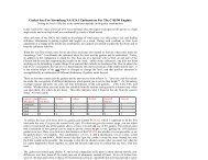
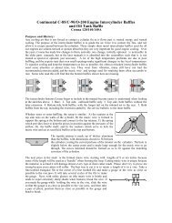
Because of the increasing difficulty of obtaining the 65 to 85 hp engines that are no longer<br />
manufactured, many would be builders have written in to ask if the 100 h.p. Continental 0-200<br />
engine can be used safely. <strong>The</strong> answer is yes; the 0-200 can be used without any reinforcement of<br />
the structure. In fact, engines up to the 108 h.p. Lycoming 0-235 can be used safely without<br />
compromising the structure or imposing a weight penalty. Engines heavier than the O-235 are<br />
not recommended.<br />
Questions have been asked, too, about the suitability of the Volkswagen engine as a substitute<br />
powerplant for FLY BABY. While no one has tried one yet, the designer does not feel that this<br />
engine has the necessary displacement to make a good-flying airplane of FLY BABY and does not<br />
recommend it.<br />
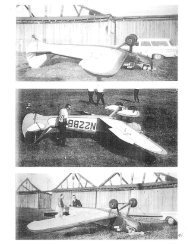
Allowance has been made for the fact that many builders will want to make minor departures<br />
from the basic design, and some acceptable variations are shown in the photo page. However, no<br />
changes should be made in really basic structure or in the size, setting, or location of the flight<br />
surfaces.<br />
Low wing monoplane configuration was chosen for the basic <strong>Fly</strong> BABY design for several reasons<br />
- structural simplicity, suitability for low-cost easy-to-rig wire bracing to fuselage and landing<br />
gear, maximum visibility for the pilot, and ease of pilot entry to the cockpit.<br />
For those desiring to convert the basic low wing FLY BABY to an entirely different machine,<br />
supplementary drawings are available for biplane wings which can be fitted to the same fuselage,<br />
tail, and landing rear as FLY BABY 1B. <strong>The</strong> basic monoplane is FLY BABY lA. <strong>The</strong> biplane wings<br />
are not designed to fold.<br />
As a biplane, FLY BABY is comparable to most other home-built biplanes with the exception that<br />
it is slightly larger than average, as is the monoplane, resulting in lighter wing loading and<br />
improved takeoff and landing characteristics. <strong>The</strong> use of sweepback on both wings is to permit<br />
interchangeability of wings between biplane and monoplane arrangements without changing the<br />
pilot's seat, which was originally determined by the wing location and balance requirements of the<br />
low wing monoplane with straight wings. To keep the pilot behind the upper wing center section<br />
i
instead of under it, the upper wing had to be located considerably forward of the lower, with<br />
sweepback used to bring the center of pressure aft to the proper location.<br />
Because of the significant differences in wing bracing, the biplane FLY BABY can use a shockabsorbing<br />
landing gear, even a single-strut type if the builder cares to work out the structural<br />
modifications. <strong>The</strong> rigid landing gear, however, has proved quite satisfactory for over 1300 hours<br />
of flying on the prototype FLY BABY and some 136 examples built from the plans. Both versions<br />
can be fitted with Edo D-1070 pontoons or equivalent home-built versions.<br />
AEROBATICS<br />
This is a subject of great concern among amateur airplane builders and pilots. For an in-depth<br />
discussion of the problem, plus others involving the structural integrity of homebuilts, see the<br />
article on pages 8-29 through 8-31 that has been reprinted from the Experimental Aircraft<br />
Association's magazine SPORT AVIATION.<br />
THE MATERIALS<br />
<strong>The</strong> structure of the standard FIX BABY is all wood which was chosen in consideration of<br />
relatively low cost, general availability, and the shop facilities, tooling, and skills possessed by the<br />
person undertaking the construction of a full-scale airplane for the first time. Anyone who can get<br />
a passing grade in a high school woodshop course should be able to successfully build a FLY<br />
BABY.<br />
Metal work, and especially welding, has been kept to an absolute minimum. <strong>The</strong>re is so little of<br />
the latter that the builder can cut his material to size and then take it to a professional shop to<br />
have the work done quickly without compromising the "do-it-yourself" requirements of airplanes<br />
to be licensed in the amateur-built category. It was intended to develop an alternate steel tube<br />
fuselage for FLY BABY, but so little interest has been shown that the designer cannot justify the<br />
time and cost of building a test specimen and making drawings.<br />
At the time FLY BABY was built in 1960, the use of some components from production<br />
commercial aircraft was permitted and still is. One FLY BABY now uses shortened wings from a<br />
Luscombe SA. <strong>The</strong> most commonly used items are engine mounts, fuel tanks, and cowlings.<br />
However, for certification as amateur-built, the airplane must be 51% built by the builder.<br />
Because the wings are wire-braced to the axles, landing gears from production airplanes should<br />
not be adapted to FLY BABY unless they are made rigid in the process. This applies to the<br />
monoplane FLY BABY; tie biplane can use a shock-absorbing gear. Be sure when adapting other<br />
gear that the wheels end up in exactly the same position as specified in the plans.<br />
Bills of materials for the necessary sizes and quantities of raw materials are listed in each of the<br />
appropriate chapters in this plans book. Such items as wing spars, longerons, and rib cap strips<br />
can be ordered from a lumber mill or specialty house cut to the proper cross-section dimensions<br />
but not to the finished length without compromising the "amateur-built" requirement. <strong>The</strong><br />
addresses of some suppliers are given in Chapter 9. Other sources can be found in the<br />
advertisements in SPORT AVIATION and the commercial magazines that feature homebuilt<br />
airplanes and recreational flying.<br />
ii
THE PLANS<br />
<strong>The</strong> method of presenting the plans for FLY BABY is quite different from the traditional "Roll of<br />
Blueprints" approach. Instead of a maze of full-size and meticu1ously dimensioned drawings,<br />
most items are presented in reduced scale with accompanying step-by-step pictorial and written<br />
instructions or a single convenient loose-leaf document. <strong>The</strong> isometric drawings are not always to<br />
true scale. In some cases, individual parts are drawn in over-size to emphasize a detail or an<br />
assembly method or undersize to avoid overlap or to fit into the available space. In such cases,<br />
the important dimensions are given.<br />
In recognition of the fact that close tolerances are hard to work to, even without the usual homeworkshop<br />
handicap of inexperience, sub-standard working area, and bare-minimum tooling,<br />
many structural items have been designed with the deliberate intention that their final<br />
dimensions be established by the procedure known as "Fit on Assembly". This eliminates wasted<br />
material and time-consuming rework when inaccuracies, which are not in themselves critical,<br />
prevent two mating parts from fitting together properly Because of this concept, many of the<br />
parts are not dimensioned in as much detail as would ordinarily be expected.<br />
<strong>The</strong> drawings also anticipate certain problems in the procurement of hardware and equipment.<br />
In many cases, sizes for sheet metal or tubular parts are a recommended minimum only. <strong>The</strong><br />
airplane is of such a size that the weight penalty resulting from a change of metal thickness from<br />
1/16" to 3/32" or even 1/8" on these parts is negligible. <strong>The</strong>refore, it is not necessary to spend a<br />
lot of time and effort trying to locate material of the exact specified size when plenty or perfectly<br />
acceptable substitute material may be right at hand.<br />
<strong>The</strong> same reasoning also applies to such "used hardware" items as fuel tanks, brakes, and brake<br />
master cylinders. Mechanical brakes are just as suitable as the hydraulic type used on the<br />
prototype FLY BABY. Since there are so many possible combinations of brakes and actuators it<br />
would be pointless to illustrate them all in the drawings. If the builder is too inexperienced in<br />
aircraft practice to determine acceptable part and material substitutions within the general intent<br />
of these drawings, he should, in the absence of experienced neighbors, consult a licensed airframe<br />
mechanic at the nearest airport or a Federal Aviation Agency Safety and Maintenance Inspector<br />
(under U.S. Gov't., Dept. of Transportation, in the telephone directory).<br />
THE WORKING AREA AND CONDITIONS<br />
Building an airplane is not a big job. It is a whole collection of little ones whose degree of<br />
simplicity or difficulty, independent of the builder's skill, is influenced to a large degree by the<br />
available work area and conditions. Airplanes similar to FLY BABY have been built in<br />
surprisingly illogical places, so it can be done without formal shop facilities.<br />
However, suitable space where the work can be left standing is desirable. Since FLY BABY breaks<br />
down to components of convenient size, a standard one-car garage with a work bench across one<br />
end is suitable for the entire job. Minimum area for building the wing is enough to lay the 4-1/2 x<br />
13 foot panel flat at a convenient working level and still allow room to work around each side and<br />
iii
the ends with space available for the standing tools. <strong>The</strong> fuselage is just over 14 feet long without<br />
the engine mount or rudder installed, and is two feet wide. Without the landing gear, the fuselage<br />
can be taken through a standard door located to permit a nearly straight approach to it.<br />
Depending on the relationships of various doors, this means that FLY BABY can be built in many<br />
rooms of a regular house and then be removed without knocking out a wall in the classic "boat-inthe-basement"<br />
tradition.<br />
Since the Weldwood glue recommended for FLY BABY must be used at temperatures above 70<br />
degrees Fahrenheit, and the application of dope to the fabric should also be done at this<br />
temperature, heat control in the working area is essential. Suitable glues are available for lower<br />
temperatures, but with no heat control the doping may have to be deferred until warm weather.<br />
Doping should not be done in a confined area without adequate force ventilation anyhow, so<br />
unless a suitable shop is available, the job should be done outdoors in good weather or taken to<br />
another shop. Nothing will kill family approval of a home-built airplane project faster than a<br />
house full of dope fumes.<br />
THE TOOLS<br />
As with the working area, FLY BABY can be built with a bare minimum of tools but the job is<br />
greatly simplified by having a proper selection for the various jobs. Items marked with an asterisk<br />
(*) in the following list are considered absolutely essential. If these are not on hand in the home<br />
shop, material will have to be taken elsewhere for the necessary work. Aside from a suitable<br />
power saw and drill press the most essential tool will be an electric hand drill and an extension<br />
cord and light. This is because so much work will be done on and inside the airplane rather than<br />
on the bench as the job progresses.<br />
SAWS<br />
DRILLS<br />
FILES<br />
Table or radial arm saw *<br />
Coping saw or jigsaw<br />
Bandsaw or bayonet saw with stand *<br />
Hacksaw *<br />
Small strongback saw or hand saw<br />
Bench drill or drill press *<br />
Electric hand drill *<br />
Drill bits to max. dia. 3/8" (with 1/4" shank for hand drill) *<br />
Suitable flat, rounded, and rat-tail files for wood and metal finishing *<br />
Coarse wood rasp<br />
Rotary file for electric drill<br />
Rotary rasp for electric drill (also called "Scotch Plane")<br />
iv
C-CLAMPS<br />
Minimum 4 6-inch *<br />
Minimum 2 dozen 3-inch *<br />
VISE (steel) *<br />
SOLDERING IRON<br />
TACK HAMMER *<br />
PINKING SHEARS<br />
BENCH SANDING DISC<br />
WELDING RIG<br />
BENCH GRINDING WHEEL SAW HORSES (2 minimum) *<br />
BLOCK PLANES GLUE BRUSHES *<br />
SCREW DRIVERS * PAPER CUPS (unwaxed2 for glue and varnish) *<br />
TIN SNIPS * COLD CHISEL OR WIRE CUTTERS *<br />
DRAW KNIFE OR SPOKESHAVE 1/8" NICOPRESS *<br />
THREE FOOT CARPENTERS SQUARE * BOX OR OPEN END WRENCHES TO 3/4" *<br />
6' STEEL MEASURING TAPE<br />
WORK PRACTICES<br />
Many work hours can be saved and the various jobs simplified by organizing the work in an<br />
efficient manner. While circumstances will dictate different procedures for different people<br />
because of equipment, availability of materials, etc., a few time-saving suggestions can be<br />
followed by almost everyone:<br />
CUT AS MANY PIECES OF A SIZE AS POSSIBLE AT ONE TIME. Much time is wasted in resetting<br />
the tools (power saw, drill, etc.) when pieces are cut singly or a few at a time on an "asneeded"<br />
basis. Consideration must be given, however to the stipulation in F.A.A. Manual 18<br />
that wood surfaces for gluing should not be exposed for more than 24 hours prior to gluing.<br />
MIX GLUE WITH SPECIFIC JOBS IN MIND. Much expensive glue is wasted by mixing too<br />
much for a particular job. <strong>The</strong> "pot life" of Weldwood glue is only four hours, so it can't be<br />
saved for tomorrow. If quite a few items are to be glued over a fairly long continuous period,<br />
like an afternoon of installing wing rib corner blocks, plan on mixing several small batches<br />
during that time. Small batches are easier to mix and there is no question of approaching the<br />
pot life limit as the job goes on. Similarly, take precautions against running out of glue in the<br />
middle of a big and fast job such as laminating wing tip bows. Mix several small batches rather<br />
than one big one, or have a helper mixing new ones as you use the first.<br />
<strong>The</strong> best applicator for Weldwood glue is a l/2" to 3/4" paint brush. If the brush is washed out<br />
in hot water before the glue sets, the brush can last for months. Weldwood is cheaper in 5-<br />
pound cans, but constant opening of the can to take out small quantities ages it rapidly. It is<br />
best to buy it in small cans.<br />
PLAN VARNISHING SO AS NOT TO BLOCK OTHER WORK. Try to save varnishing that will<br />
hold up other work in a particular area for the end of the work period so that it can dry<br />
overnight or between sessions. When wet varnish is on some parts while others are being<br />
worked on, be sure that shavings and chips don't fall in the varnish. Remember that dust from<br />
saws and grinders can float all over the shop and settle on a wet varnish job clear across the<br />
room from the tool.<br />
v
Don't open the varnish can. Poke two nail holes on opposite sides of the lid and seal them with<br />
pieces of masking tape. Pull the tape and pour varnish into a paper cup for mixing with<br />
turpentine for small jobs. <strong>The</strong> can gets messy if varnish is poured over the lip, and after several<br />
openings for pouring small quantities, the varnish begins to thicken and scum over. Although<br />
cheaper by the gallon, it is best to buy varnish in quart cans. Be careful NOT to use WAXED<br />
cups for varnish, glue, or dope. "Hot cups" are fine, but not Styrofoam or plastic cups.<br />
USE SYSTEMATIC WORK HABITS. Try to plan the work on individual jobs ahead for several<br />
days so as to have all the necessary material on hand and organize the most efficient sequence<br />
for doing things. Much time can be lost by wondering "what to do next?" and then figuring out<br />
how to go about it. Try to work on related jobs in sequence so that wood parts for several can<br />
be cut at one time, etc Try to set up specified times for working, with an ideal objective of<br />
being able to get some little thing, even if its only removing the clamps from yesterday's work,<br />
done every day.<br />
AVOID OBSTACLES TO PROGRESS. One of the major roadblocks to completion of any home<br />
workshop project is objection by authoritative members of the family if legitimate family<br />
obligations and relationships are neglected for the project0 This is a political matter beyond<br />
the scope of this technical document, but is nevertheless a major item for consideration.<br />
Other than the family situation, there are three major human causes of wasted time in<br />
construction projects:<br />
(1) <strong>The</strong> first is the eager friend who is anxious to be helpful but doesn't know anything about<br />
building airplanes or even handling tools. By the time you show him how, check his work;<br />
and generally do it over, you could have done it several times yourself in addition to the job<br />
you were working on. <strong>The</strong> exact and highly desirable opposite of this type, and<br />
unfortunately very rare, is the experienced person who can be handed a job and forgotten<br />
for a while as he gets it done with no fuss.<br />
(2) <strong>The</strong> second time-killer, more often plural than singular, is the curious and friendly type<br />
who drops around from time to time "to see how you are doing" and brings a friend along<br />
who has to have the whole project explained in detail from the very beginning. No work<br />
can be done at all during most of these visits, and the visitors are very seldom inclined or<br />
even qualified to help. A sub-category of this type is the one with whom a little knowledge<br />
is a dangerous thing, and who is always trying to improve your design to death by<br />
suggesting all sorts of things from little refinements to major rearrangements that will be<br />
made with YOUR time, money, and materials.<br />
One unforeseen by-product of both categories of this second type is the added expense to<br />
the overall job resulting from the amount of your groceries, coffee, beer: etc., that they<br />
consume while sitting around keeping you from working.<br />
vi
(3) <strong>The</strong> third major thief of your working time is yourself. As the plane begins to go together it<br />
is entirely too easy to gaze dreamily at it by the hour, admiring your own handiwork and<br />
engaging in all sorts of flights of fancy while sitting in the cockpit of an unfinished fuselage<br />
perched on a pair of sawhorses0 Even if you don' t feel particularly ambitious when you go<br />
out to the shop; or time is short, try to make sane tangible progress. Don't goof off for one<br />
whole work period by kidding yourself with the thought that you'll really bear down on it<br />
"tomorrow" or even "next week'.<br />
Overdoing the improvements can be a personal matter, too, although in some cases it<br />
stems from improving skill as the job progresses <strong>The</strong>re may be such a difference between<br />
the first few ribs you built and the last that you want to scrap the early ones and do them<br />
over. Your own standards and time/cost considerations will be your only guides here.<br />
RECORDS AND PAPERWORK<br />
Keep a record of all purchases of material for your FLY BABY, whether new or used. This will<br />
keep you informed of actual costs, will enable you to answer the inevitable question that you will<br />
hear hundreds of times: "How much did it cost ya, mister?", and will enable you to help friends<br />
who are considering a homebuilt and yourself when planning another. Most important of all,<br />
however, it will enable you to establish a true cash value for your machine when the tax assessor<br />
comes around. If he is not experienced in evaluating; aircraft (some states tax airplanes as<br />
personal property while others use an excise tax) he may arbitrarily assign an unfairly high value<br />
An the absence of substantiating figures Also, sales slips can show that state sales taxes have<br />
been paid on the raw materials, another concern of the tax people when the plane is finished.<br />
Try, too, to keep at least a rough check on your working time. <strong>The</strong> next-most-asked question from<br />
the spectators is: "How long did it take you to build it?" <strong>The</strong>re is satisfaction in being able to snap<br />
off a concise and authoritative answer, either in terms of man-hours or days, weeks, and months.<br />
It is a very good idea to start the airplane logbook at the time you start construction Information<br />
as to the source and grade of raw materials can form a valuable historical record, and a record can<br />
be kept of essential pre-finish FAA inspections. Since a homebuilt is not pinned down to an<br />
approved bill of materials that is a matter of record as in the case of type-certificated production<br />
models, a record should be included of the type of covering material, type of dope whether nitrate<br />
or butyrate, and even the type of hydraulic fluid used in the brakes. You may forget over<br />
subsequent years, or a new owner not know at all if it isn't recorded, with a resulting complication<br />
of maintenance problems.<br />
Other paperwork directly concerned with registration and certification of your airplane is covered<br />
in Chapter 8, ASSEMBLY, TEST, AND FLYING.<br />
vii
CONSTRUCTION PROCEDURES<br />
Those who are generally familiar with aircraft construction and repair procedures should have no<br />
trouble at all in any phase of building FLY BABY Those unfamiliar with aircraft practice, or skilled<br />
only in one specialized field, should consult their more experienced friends before proceeding. In<br />
any case, it is strongly recommended that anyone building FLY BABY or any other homebuilt<br />
airplane obtain a copy or Federal Aviation Agency Manual 18, MAINTENANCE, REPAIR AND<br />
ALTERATION OF AIR FRAMES, PROPELLORS, AND APPLIANCES, available from the<br />
Government Printing Office, Washington 25, D.C., or some aircraft supply stores for $1.50. This<br />
book is "<strong>The</strong> Bible" on all phases of aircraft construction and repair procedure. *<br />
It is impossible to detail fabrication procedures down to the fundamental level of how to hold the<br />
hammer. <strong>The</strong> drawings and instruction pre-suppose a competent skill level. <strong>The</strong>re are, however,<br />
certain construction procedures associated with aircraft standards of quality that should be<br />
mentioned.<br />
WOOD<br />
Wood aircraft construction differs considerably from traditional cabinet and furniture-making<br />
procedure. <strong>The</strong>re are no mortises, tennons, or dovetail joints in aircraft. All wood-to-wood joints<br />
are by glue in shear or by bolting. Bolt heads or nuts bearing against bare wood opposite a metal<br />
fitting should be backed up by large-diameter wood washers. Wood screws are never used for<br />
joining; small nails are used to hold glue joints under pressure while drying and then become<br />
entirely redundant. Wood surfaces are protected from damage during clamping by use of<br />
clamping backup blocks to distribute the load.<br />
With the exception of' the wing spars and the slotted rib cap strips, it is much cheaper for the<br />
builder to buy his spruce lumber in planks and saw it to size himself than to have it finished at a<br />
mill. <strong>The</strong> cap strips can be cut <strong>The</strong> cap strips can be cut from standard l/4" "Cap Strip Stock" on<br />
any circular saw, but cutting the 1/8" x 1/8" slot calls for exactly the right size. blade. A "planer"<br />
blade should be used for finished rip cuts on all non-plywood wooden parts in FLY BABY.<br />
Suppliers of aircraft grade wood that advertise in SPORT AVIATION, magazine of the<br />
Experimental Aircraft Association (EAA) have been advised of the size and quantity of the FLY<br />
BABY materials, and will be able to make "package" deals at fixed prices.<br />
METAL<br />
while there is very little metal in FLY BABY, certain practices must be observed. Most of the<br />
S.A.E. 4130 sheet steel fittings can be bent cold by hammering in a vise, However, the jaws should<br />
have a slight radius to prevent serious weakening of the metal at the outside of the bend.<br />
Rounding off the corners of metal parts is not necessary, but is a matter of craftsmanship. ALL<br />
metal parts should be protected against corrosion by suitable painting, either with Zinc Chromate<br />
Primer or a rust inhibitor like Rustoleum <strong>The</strong> best method is to have them cadmium plated.<br />
* Out of print. Now sold by EAA along with many other "How-to-do" books.<br />
viii
MISCELLANEOUS HARDWARE<br />
<strong>The</strong> nuts and bolts are called out in the bills of materials, or parts lists, by the "AN" number,<br />
meaning Army-Navy standard. <strong>The</strong>se can be ordered from aircraft stores or mail-order houses by<br />
the numbers, which have easily identified meanings. An AN-3-7A bolt is 3/16" in diameter as<br />
indicated by the first number, which varies by sixteenths of an inch. <strong>The</strong> second number indicates<br />
the length, the distance from under the head to the far end Of the threads in eighths of an inch.<br />
However, 8/8 do not make an inch in this case. An AN-4-10 is a l/4" bolt one inch long and an<br />
AN-5-11 is a 5/16" bolt 1-1/8" long, and so on. <strong>The</strong> letter "A" on tile end of the number means the<br />
bolt is NOT drilled far a cotter pin. With no letter, it's drilled. All bolts used in FLY BABY are<br />
cadmium-plated steel.<br />
In aircraft installation, it is customary, but not mandatory, to install bolts with the heads pointing<br />
either forward relative to the airplane, outboard or upwards. Where bolts through wood in FLY<br />
BABY are loaded in shear, the area of the bolt is enough so that the hole doesn't have to be<br />
bushed. <strong>The</strong> only bushings actually required are for protection in wear areas, as where wing,<br />
attach bolts are frequently inserted and removed. When installing wide wood washers under nuts<br />
or bolt heads that bear on wood, be sure to varnish the wood UNDER the washer before installing<br />
it permanently. Except where specifically indicated, all nuts used in FLY BABY are AN-365 type<br />
elastic stop nuts. Likewise, moving metal parts are joined by clevis pins secured with cotter pins<br />
except as noted. Washers should be used between the cotter pin and the metal surface.<br />
<strong>The</strong> 1600-pound-minimum strength turnbuckles are secured on the fork, end by clevis pins while<br />
the wires through the eye are reinforced with AN-lO0-4 thimbles and secured with 1/8" Nico<br />
sleeves. By using the same size of wire all over the airplane, the wire purchase and fastening<br />
problems are simplified. It should not be necessary to buy a 1/8" Nicopress tool (they cost about<br />
$22.00), for many mechanics and most aircraft repair shops have them. Turnbuckles are safetied<br />
by either single or double wrap with #41 safety wire per Manual 18.<br />
When buying nuts and bolts, washers, cotter pins. etc., don't get just the exact number specified<br />
by the parts lists. No one ever has too many of these items. For AN-3 bolts and AN-393 clevis<br />
pins especially, buy a good variety of lengths between the longest and shortest specified. No one<br />
ever seem to have a surplus of AN-960-10 washers on hand, either.<br />
A SUGGESTION<br />
If you are completely inexperienced in aircraft matters, it is suggested that you associate<br />
yourself with a local chapter of the Experimental Aircraft Association (EAA), a national<br />
organization devoted to amateur aircraft builders. Write to Headquarters, EAA, 3000<br />
Poberezny boulevard, Oshkosh, Wisconsin, 54903-3086. Membership is $35.00 per year, and<br />
worth every cent of it for the magazine SPORT AVIATION alone. Write to EAA for the address<br />
of the chapter nearest you. Practically all of the items you will need to build your FLY BABY<br />
are advertised in the pages or SPORT AVIATION.<br />
ENOUGH OF GENERALITIES! GET TO WORK ON YOUR FLY BABY!<br />
ix
1 SECTION 1 - THE FUSELAGE<br />
<strong>The</strong> all-wood fuselage of FLY BABY is both a simple and a rugged structure, and lends itself easily<br />
to minor alterations to accommodate different landing gear, cockpit enclosures windshield, etc.<br />
<strong>The</strong> main structural cross-members that support the landing gear are entirely independent of the<br />
key wing-support structure, so these members can be moved around as desired without affecting<br />
anything else. <strong>The</strong> turtledeck structure aft of the cockpit is removable so that flying is possible<br />
with an alternate open cockpit or closed canopy arrangement.<br />
Some people may be concerned over the absence of a "Turnover Structure" behind the cockpit.<br />
Such an item cannot be installed without building up a structure above the pilot's head, which is<br />
not compatible with the classic lines of this traditional open-cockpit design. Instead, the box-spar<br />
vertical fin structure does this job and only breaking the fuselage in two will keep it from serving<br />
its purpose of protecting the pilot should the plane go over on its back following a landing in<br />
rough terrain.<br />
<strong>The</strong> fuselage is built by making two side layouts on a flat surface just like a "Box" model airplane.<br />
Much of the complex gusseting of older wood-truss homebuilt fuselages has been eliminated by<br />
skinning each side with 1/8" plywood, which itself acts as a super gusset as well as adding<br />
strength to the fuselage by its function as a shear web. In the nose section, a second inner<br />
plywood shear web is added to help transfer the engine mount loads through bolts to the fuselage.<br />
<strong>The</strong> arrangement of the fuselage truss members aft of the cockpit has been carefully chosen to<br />
simplify the joint-and-gusset problem so that only two types of joints result. Because of the<br />
plywood covering, the diagonal side members do not carry loads as they do in a welded steel or an<br />
ordinary wood truss. <strong>The</strong>ir main function is to support and stiffen the plywood.<br />
Up forward, the main cross-load carrying members for the landing gear and wing supports are<br />
built rigidly into the double bottom longeron structure of each side. By the time these are<br />
anchored by the end blocks and inner plywood skin, NOTHING is going to move them. If you<br />
manage to knock any one of these four main members loose you're going to need a whole new<br />
airplane. <strong>The</strong> double longerons, boxed on both side with plywood, result in a "Double Keel" of<br />
great strength for maximum safety. <strong>The</strong> heavy plywood gussets and metal fittings at the landing<br />
gear attach points eliminate the need for diagonal bracing across the bottom in this area. It is<br />
believed that the fuselage is adequate for 125 horsepower engines as presently designed. <strong>The</strong> only<br />
problem is one of balance because of the increased weight of the larger engine.<br />
Normally, fuselage structure is stiffened by diagonal members across each bay. This is impossible<br />
in the area occupied by the pilot, so the problem is taken care of in the cockpit by the use of<br />
quarter-circle corner bows covered with plywood, which serve the same purpose and leave the<br />
spaces open.<br />
<strong>The</strong> main fuselage structure is glued together, with various attachments bolted on. For maximum<br />
strength and to avoid dependence on glue in such critical areas. the tail post and the front<br />
bulkhead, which supports the engine mount, are bolted to the doubled main side structure<br />
through metal fittings. Exterior wood surfaces are protected from the weather by fabric laid on<br />
over the wood and all inside wood is varnished.<br />
<strong>Page</strong> 1-1
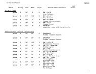
FUSELAGE - BILL OF MATERIALS<br />
WOOD<br />
Number Material Dimensions Use .<br />
4 plywood 1/8" x 4’ x 8' Sides, gussets, etc,<br />
124 ft spruce 3/4" (4 pieces 15', 2 pieces 7') Longerons, diagonals<br />
25 ft spruce 1/2" x 3/4" Diagonals<br />
7 spruce 1/4" x 1" x 6' Turtledeck stringers<br />
120 ft any wood 3/8" x 3/8" up to 15' Belly stringers<br />
2 spruce 3/8" x 3/8" x 52" Fin flanges<br />
1 plywood 1/4" x 4' x 4" Formers, anchors<br />
1 plywood 3/8 x 2' x 32" Firewall former<br />
I plywood 3/4" x 2' x 4" Bows*, gussets<br />
I hardwood 1" x 2" x 9" Tail spring anchor<br />
1 spruce 3/8" x 2" x 12" Fin filler<br />
1 spruce 3/8" x 3" x 3" Fin filler<br />
2 hardwood 3/4" x 1-1/2" x 20" Station I uprights<br />
2 spruce 3/4" x 1-1/2" x 12" Station 11 uprights<br />
4 spruce 1/4" x 1/4'" x 16" Underfin flanges<br />
24 spruce 1/16" x 3/4" x 36" Bows**<br />
5 spruce 3/4" x 5" x 22-1/2" Station 2-54 X-pieces<br />
8 spruce 1/2" x l/2" x 18" Floor beam flanges<br />
2 spruce 1/2" x 2" x 4" Hinge tube supports<br />
HARDWARE<br />
2 dural or steel 1/8" x 1-1/2" x 22" rt angle Engine mount anchors<br />
14 bolts AN-4-14A (or longer) *** Attach above<br />
14 nuts AN-365-428<br />
1 steel .063(or more) x4-1/2" x 10-1/2" Tail post anchor<br />
7 bolts AN-3-12A<br />
7 washers AN-960-10<br />
4 steel .093" x 3-3/8" x 5-1/8" Wing wire anchors<br />
4 aluminum 1/2" x 1" x 3-3/8" Wing wire anchors<br />
16 bolts AN-3-14A<br />
7 bolts AN-6-16<br />
7 nuts AN-310-6<br />
23 nuts AN-365-1032<br />
36 nutplates AN-366-F-832 Cowling hold down<br />
72 wood screws AN-545-4-4 Hold nutplates<br />
nails 1/2" #20<br />
Weldwood glue<br />
7 cotter pins AN-380-3-3<br />
* Alternate to building up laminated bows.<br />
** Alternate to expensive 3/4' plywood.<br />
*** See Figure 1-16 for alternate installation.<br />
<strong>Page</strong> 1-2
FUSELAGE LAYOUT<br />
<strong>The</strong> main requirement for building the fuselage is a flat working area at least 2-1/2. x 15 feet,<br />
preferably a bench that nails can be driven into. <strong>The</strong> shop floor will do if a couple of 34'" plywood<br />
sheets are butted together and laid down.<br />
1. Using the dimensions of Figures 1-1 and 1-2, lay out a full size fuselage side view, using the<br />
top of the top longeron as the reference line. <strong>The</strong> curve of the bottom longeron is drawn most<br />
easily by using one of the longerons themselves as a drawing spline.<br />
2. Cut about 60 hold-down blocks from 1/2" plywood, 1" x 3". Having the blocks thinner than<br />
the fuselage members allows the plywood skin to be laid on the fuselage frame while still held<br />
by the blocks and if made of plywood the small blocks will not split when nailed down.<br />
3. Put the top longeron in position and hold it with enough pairs of blocks as shown to hold it<br />
securely. Do not have the blocks too tight or it will be hard to lift the completed frame out of<br />
the blocks. By using the same blocks twice without moving them both side frames will match<br />
exactly.<br />
NOTE<br />
Put pieces of wax paper on the board at each glue joint to keep the<br />
glue from sticking the frame to the board.<br />
4. Put the lower longeron in position, starting at the rear with pairs of blocks and working<br />
forward. Note the extra length ahead of the forward upright (Station 1), held by an extra pair<br />
of blocks, to give leverage for the final bend. More "Inside" blocks will be used on the curve<br />
than "Outside" blocks. <strong>The</strong> pair of blocks "X" is located as shown at the end of the straight<br />
section of the lower longeron. Block "Y" is located at the key point for forming the bend in the<br />
longeron.<br />
5. Put in the intermediate (straight) lower longeron between Stations 1 and 6, holding it with<br />
pairs of blocks. After a snug fit to the lower longeron at Station 6 is obtained, remove the<br />
longeron and glue to the ends, and reinstall. Cut and fit in 3/4" plywood filler block per Detail<br />
A of Figure 1-1 and glue in place.<br />
6. Cut and install the uprights between the lower and upper longerons at Station 3 and 5<br />
through 8, holding 'each with two pairs of blocks. <strong>The</strong> fit should be such that the uprights<br />
must be pressed into place but not forced hard.<br />
NOTE<br />
Glue on butt joins like these does not strengthen the structure or hold it together, it merely seals<br />
the open end grain of the wood.<br />
<strong>Page</strong> 1-3
<strong>Page</strong> 1-4
<strong>Page</strong> 1-5
Treat the Station 9-10 diagonal as an upright, using two pairs of holding blocks. See Detail H<br />
of Figure 1-2 for spacing at Station 9. Notice that the upright at Station 6 is 1/8" thinner than<br />
all the others as shown in Detail F of Figure 1/2, and that the Station 3 and 5 pieces between<br />
the two lower longerons MUST line up with the upper pieces. Do NOT install the 3/4" x 1-<br />
1/2" upright at Station 11 at this time.<br />
7. Cut and fit the forward Station 1-2 diagonal. When properly fitted, only one block is needed<br />
to hold it in place. Repeat for the Station 3-4 diagonal.<br />
8. Cut and fit the Station 2-3, 14-5, and all the remaining diagonals toward Station 10. If cut<br />
and fitted properly, no blocks will be necessary to hold them in place. All diagonal aft of<br />
Station 6 are 1/2" x 3/4".<br />
9. Fit a piece of 1/8" x 1-1/2" plywood over the thin upright at Station 6 and glue it in place per<br />
Detail F of Figure 1-1. Hold with nails until the glue dries.<br />
10. Cut a piece of 1/8" plywood from a standard 4' x 8' sheet to slightly over the dimensions from<br />
Station 6 to a few inches aft of Station 11. Be sure that the top edge is straight, and square the<br />
forward edge (Station 6) to it.<br />
11. Lay this plywood on a suitable open-end work area like a workbench or table-saw table and<br />
scarf a 12:1 bevel along the Station 6 edge per Detail F of Figure 1-1. This can be done with a<br />
sharp block plane, a good draw knife if you are good, or with a "Scotch Plane".<br />
12. Lay the plywood in place to be sure that it fits. If it does, hold it down with a couple of<br />
aircraft nails driven in part way, and lay out the centerlines of all the structural members that<br />
the plywood will be glued to. <strong>The</strong> easiest way to do this is to project the centerlines of the<br />
diagonals and uprights beyond the structure onto the work surface before the plywood is laid<br />
down. Centerline for upper longeron can be located by measuring in from the edge. <strong>The</strong> same<br />
process can be used for the bottom longeron if the lower edge of the plywood has been<br />
trimmed to it.<br />
13. Make up at least two nailing strips 23" long per Figure 1-3, with nails started at<br />
approximately 1-inch intervals. <strong>The</strong>se are for use in the splice area. Some really meticulous<br />
builders use nailing strips everywhere to hold plywood to structure only until the glue sets,<br />
but it is hardly worth the effort for a design like this. At this station, the nails must be<br />
removed because another piece of plywood goes over the joint.<br />
14. Cut two pieces of 5/8" x 1/2" wood to fit under the plywood splice plate at Station 6 as a<br />
backup for the nailing.<br />
15. Mix up enough glue to cover all the structure from Station 6 aft and get it on the frame FAST<br />
with a 1/2" to 1" paintbrush.<br />
16. Lay the plywood in place, and start nailing. Approximately 1-inch spacing for 1/2-inch No. 20<br />
nails is about right. Don't bother to actually measure this spacing. PUT WAX paper under<br />
one nailing strip and use it to hold down the very forward edge Of the bevelled edge of the<br />
plywood at Station 6. <strong>The</strong> nails should go through the bevel about 1/4" in from the edge.<br />
Actually, the nails make the wood strip act as a long clamp.<br />
<strong>Page</strong> 1-6
<strong>Page</strong> 1-7
17. While the rear plywood section is setting up, prepare the forward section in the same way.<br />
Notice that the bevel is on the INSIDE face of the plywood this time!<br />
18. Apply the forward plywood the same way after pulling off the nailing strip, but use two<br />
nailing strips at the splice, one with the nails about 1/4" in from the edge and the second<br />
immediately forward of the first. Because of the glue that will squeeze out of the joint, wax<br />
paper under the strips is essential to keep them from getting glued down.<br />
19. Remove the plywood-covered fuselage side frame from the blocks. Trim the plywood if the<br />
edges are ragged, but leave at least 2" aft of Station 11.<br />
20. Make a second side frame inside the blocks nailed dawn for the first. Fitting the diagonals will<br />
be a somewhat more exacting job this time as the blocks are already there and will not be put<br />
in position after the diagonal has been fitted. Remember that this second frame is for the<br />
RIGHT HAND SIDE, so the plywood splice plate at Station 6 will be against the table instead<br />
of on top of the frame.<br />
21. Since the plywood goes on the "Down" side of this second frame, the frame will have to be<br />
removed from the blocks before the plywood is applied. However, the butt-glue-joints will<br />
not hold it together for this rough treatment, or even against the tension of the curved lower<br />
longeron. Cut some scraps of 1/8" plywood and nail them over the various joints as gussets.<br />
Do not use glue, but drive one l/2"-20 nail for each frame member in all the way. <strong>The</strong> whole<br />
gusset, nails and all, can easily be pulled off later.<br />
22. Remove the gusseted frame from the blocks, turn it over on a flat surface and apply the<br />
plywood as in Steps 10 through 16. When putting temporary backup wood under the plywood<br />
splice plate of Station 6, don't forget to add the thickness of the temporary gussets that are<br />
raising the frame a bit above the work surface.<br />
FUSELAGE ASSEMBLY<br />
Before starting to assemble the fuselage, cut 16 quarter-round "A" gussets from 1/8" plywood and<br />
26 half-round "B" gussets per Details A and B of Figure 1-4. Cut 12 3/4*" corner bows per Detail<br />
C. All are simple arcs of circles with radii as indicated.<br />
Next, cut five fuselage frame spreader bars from any convenient size pieces of wood and notch as<br />
shown in Detail D of Figure 1-4. <strong>The</strong> fuselage is now ready for assembly.<br />
<strong>Page</strong> 1-8
<strong>Page</strong> 1-9
1. Lay three spreader bars on a flat surface, and fit the fuselage sides into them UPSIDE DOWN<br />
as shown in Figure 1-5. Add the two remaining bars to the "Top" with the rear one at Station<br />
5.<br />
2. Square the sides and the front end as shown, and after a double-check of the nose from the<br />
opposite side to be SURE that it is square, tack on two cross-strips of wood aft of Station 6 to<br />
assure the rigidity of the structure.<br />
3. Build up wing support Stations 3 and 5 according to Steps A through D of Figure 1-6. <strong>The</strong><br />
curves for the plywood faces of Step D can be marked to size by notching the straight sections<br />
to fit and then penciling around the corner bows. Be sure to varnish the areas inside the<br />
structure before putting on the second piece of plywood.<br />
4. Landing gear support Stations 2 and 4 are built up the same way except that corner bows are<br />
not used. Do not build in Station 2 until after the firewall is mounted.<br />
5. <strong>The</strong> shapes and locations of the various 3/h" plywood filler blocks that anchor the Station 2<br />
through 5 cross members to the lower double-longeron structure are determined from the<br />
details of Figure 1-7 as keyed to Figure 1-1. <strong>The</strong> dimensions are not critical, but should not be<br />
less than shown. Note that the blocks at wing support Stations 3 and 5 are notched out 3/16"<br />
to allow the wing fittings to slip through. <strong>The</strong> holes in the rear blocks at Station 3 for the<br />
aileron push rod are a bit under-size at this stage deliberately.<br />
6. Glue the blocks to the outer plywood skin after pressing them tightly against the plywood of<br />
the cross-members per Step E of Figure 1-6.<br />
7. Cut and fit 1/8" plywood to form an inner covering for the double lower longeron structure<br />
per Step F of Figure 1-6. Don't forget to varnish the insides before putting on the plywood,<br />
and then drill a vent hole at the bottom of each closed area. It is best to drill the hole in the<br />
plywood before you put it on.<br />
NOTE<br />
<strong>The</strong> work of Steps 3 through 7, above, results in Box Structure, which should be<br />
inspected and approved by an FAA inspector before being closed up. He may not<br />
insist on it for this particular piece of structure, but it is YOU responsibility to notify<br />
him. Show him the drawings way ahead of time, and you might not be held up at this<br />
point by having to wait for his approval.<br />
[<strong>The</strong> above note is included for historical purposes. <strong>The</strong> FAA no longer requires these kinds of<br />
inspections. RJW]<br />
8. Mark the location of the wing spar pin holes on Stations 3 and 5 per the cross-section views of<br />
Figure 1-9. <strong>The</strong>y can be drilled at this time, but it is a good idea to wait and see if the wings<br />
line up properly.<br />
9. With Stations 3 through 5 in and anchored, the structure is now sufficiently rigid to allow<br />
removal of the spreader bars so that it can be turned over for working at more convenient<br />
angles.<br />
<strong>Page</strong> 1-10
<strong>Page</strong> 1-11
<strong>Page</strong> 1-12
10. Starting at Station, 6 and working toward the tail, cut, fit, and install the 3/4" square cross<br />
pieces and diagonals per Figure 1-8, using the half-round "B" gussets of Figure 1-4 nailed and<br />
glued to the OUTER faces of the longeron ONLY. <strong>The</strong> gussets at Station 6 are only temporary,<br />
and are nailed in place but not glued. Do not install cross pieces aft of Station 8 at this time.<br />
11. Starting again at Station 6 and working aft, install the diagonals per the cross-section views of<br />
Figure 1-9 with two type "A" gussets at each end per Detail A of Figure 1-4. Note 3/36" holes<br />
drilled for drainage. Cut 3/4" square notches in the middle of Type "B" gussets and doublegusset<br />
remaining Figure 1-8 diagonals per Detail B of Figure 1-4. Drill drain holes in bottom<br />
gussets of lower longerons before installing notched top gusset.<br />
12. Build up the rudder post per Figure 1-10. Lay out the proper shape on a piece of 1/8"<br />
plywood and cut to exact outline. Glue a 3/8" square strip of spruce down each side. Since it<br />
can't make the sharp bend at the bottom, let it project straight, and fit bottom piece of 3/8"<br />
solid wood as shown. Add 2-inch filler blocks to back-up hinge bolts where shown, and glue<br />
on top plywood. This is again Box Structure, requiring inside varnishing and FAA approval<br />
per Note of Step 7.<br />
13. Using C-clamps at top and bottom, clamp 3/4" x 1-1/2" uprights temporarily in place at<br />
Station 11 (the upright on the left side is 5/8" x 1-1/2"). Bevel the rear edges so that they fit<br />
squarely against the rudder post when it is held in place. <strong>The</strong> sides of the rudder post will<br />
also have to be beveled so that the plywood projecting past the Station 11 uprights fits the post<br />
snugly.<br />
14. Cut a piece of 1/8" plywood to fit the area between the Station 9-10 diagonal and the rear of<br />
the Station 11 upright, and glue it in place on the LEFT inside of the fuselage. <strong>The</strong> purpose of<br />
this is to reinforce the plywood so that an access hole can be cut in later.<br />
15. Using C-clamps from the top and the rear, glue in the Station 11 up rights. While they are<br />
drying, clamp and glue in the two half-round 3/4" plywood blocks of Detail I, Figures 1-2 and<br />
1-11 and glue 2" triangles of 3/4" plywood into the Station 9 corners per Figure 1-11.<br />
16. After the clamps of Step 15 have been removed, glue and clamp in the rudder post, being sure<br />
that it is perpendicular in both axes. While it is drying, add the 3/4" square cross piece shown<br />
21" ahead of the rudder post on the top longeron layout of Figure 1-8 and cut and fit the<br />
Station 9 1" x 2" hardwood tail spring bolt support. Anchor this with 3/4" plywood triangles<br />
notched and fitted per Figure 1-1l.<br />
17. Fit 3/4" square cross pieces between top and bottom longeron pairs tight against the rudder<br />
post per Figures 1-8 and 1-11. Because of the slope of the lower longerons, it will be necessary<br />
to bevel the bottom cross piece so plywood can fit across the longerons later. Clamp the cross<br />
pieces to the rudder post while the glue dries.<br />
<strong>Page</strong> 1-13
<strong>Page</strong> 1-14
<strong>Page</strong> 1-15
<strong>Page</strong> 1-16
<strong>Page</strong> 1-17
18. Bend up a sheet of .032 steel so that it just fits the tailpost/fuselage intersection. It is held on<br />
each side by three 3/l6" bolts through the outer plywood and the uprights, and through the<br />
tailpost by the two lower hinge bolts and one other as shown in Figure 1-11. Be sure to varnish<br />
the wood under the anchor before installing it, and paint or cadmium plate the anchor. See<br />
Also Figure 1-2, cross-section B-B.<br />
19. Install the 3/4" square cross piece shown 7" ahead of the rudder post on the top longeron<br />
view of Figure 1-8 and Figures 1-11 and 1-12. Note that this is cut half-way through from the<br />
bottom for control cable clearance. Cover the area from the previously-installed cross piece<br />
21" ahead of the rudder post to the rudder post with 1/8" plywood in TWO PIECES, butted<br />
together on the centerline of the 7" crosspiece. <strong>The</strong> purpose of the crosspiece is to stiffen the<br />
plywood ahead of the cutout in the piece of small plywood that is cut out per Figure 1-12 to<br />
allow the elevator horn to protrude through. Nail and glue 1/8" plywood below the lower<br />
longerons from Station 9 to the rudder post AFTER the underfin side plywood anchor stripes<br />
have been nailed and glued in place per Figure 1-13. Drill drain holes in the bottom plywood<br />
at the corners of Stations 9 and II and trim plywood flush with sides of longerons.<br />
20. Build up the underfin structure as shown in Figure 1-13. <strong>The</strong> 1/4" square flanges provide side<br />
surface for the plywood side pieces to be nailed and glued to. Note the cutout at the rear<br />
center of the bottom rib to allow access to the tail spring support bolts that go through the<br />
bottom of the tail post.<br />
FUSELAGE SECONDARY STRUCTURE<br />
<strong>The</strong> secondary fuselage structure consists of those parts added after the main framework has been<br />
assembled per instructions in the earlier portions of this chapter. Since most of these are not<br />
primary load-carrying parts, the builder has great leeway in the use of sizes and materials other<br />
than those specified. <strong>The</strong> "Turtledeck" around and aft of the cockpit (see Section 6) was designed<br />
to be removable and interchangeable with an enclosed-type canopy structure, but either type of<br />
structure can be built on permanently if desired. An item like the forward slope of the instrument<br />
panel is entirely arbitrary. Tall pilots would probably prefer a greater slope while short pilots<br />
would want it more nearly vertical.<br />
1. Cut firewall Former No. 1 from 3/8" plywood per Figure 1-14 and the three top fuselage<br />
formers at Stations 6, 7, and 8 from 1/4" plywood. A strip of wood with a nail as a pivot and a<br />
hole for a pencil makes a good compass to swing long arcs of circles (Figure l-15).<br />
NOTE<br />
<strong>The</strong> lower portion of the No.1 Former on Figure 1-14 is out of scale, so use the<br />
dimensions as written.<br />
<strong>Page</strong> 1-18
<strong>Page</strong> 1-19
2. Build up a 3/4" wide by 3/4" deep flange on backside of top portion of Former No.1 per<br />
Figures 1-14 and 1-15. <strong>The</strong> only purpose of this is to serve as a base for the nutplates that<br />
anchor the forward metal turtledeck, and can be built up of scraps of 3/4" plywood trimmed<br />
to fit or can be laminated as a single bow by tracing the curve off on a work surface, drawing a<br />
line set inside 3/4", driving nails along it, and laminating strips of 1/l6" x 3/4" wood in place.<br />
3. Glue in Former No.1. After it has set, trim the excess side plywood and install the landing<br />
gear support at Station 2 per Figure 1-6. When installing the inner plywood between Stations<br />
1 and 2, carry the plywood upward along the diagonal per Figure 1-15.<br />
4. Cut a 1/8" x 1-1/2" x 1-1/2" 2024 dural angle, trimmed flush with the top and bottom<br />
longerons, to fit the firewall corners per Figure 1-16. Do not drill or install at this time.<br />
NOTE<br />
If you have difficulty getting dural angle, the weight penalty is negligible if you use 1/8"<br />
mild steel angles easily obtainable from most metal supply stores. An alternate is to bend up<br />
3/32" or 1/8" sheet steel, but this job will probably have to be done at a metal shop where a<br />
22" piece can be bent on a brake.<br />
5. Install Formers 6 through 8 on the BACK SIDES of the 3/4" top across pieces at those<br />
stations, and glue in the six 1/4" x 1" stringers. Don't try to save weight by making the<br />
stringers any thinner. Note from Figure 1-15 that the forward ends are notched to take a<br />
2"strip of 1/8" plywood.<br />
6. Fit the plywood strip to the stringers at Station 6 by laying an over-size strip, GRAIN<br />
PARALLEL TO STRINGERS, in place and marking the forward edge by using the front of<br />
Former 6 as a guide. Measure back 2 inches for the rear line, trim, and install. <strong>The</strong> fabric will<br />
have a smoother appearance if the plywood is scalloped per the dotted lines of Detail A,<br />
Figure 1-15, after installation.<br />
7. Build up box-construction seat support beams and install with triangular glued and nailed<br />
corner blocks per Figure 1-17.<br />
Note positions of rudder cable holes, control stick bearings, and belly stringers for future<br />
reference.<br />
8. Install combined floorboard beams and wing hinge tube supports between Station 2 and 3<br />
per Figure 1-18. <strong>The</strong> holes for the 1" I.D. tube can be drilled any time, but it is easiest to do it<br />
now, before the beams are installed. If the tubes are installed now, be sure to leave the<br />
matching fitting on the wing root undrilled until the wing can be installed on the fuselage and<br />
proper alignment of the tube and the hinge assured.<br />
<strong>Page</strong> 1-20
<strong>Page</strong> 1-21
<strong>Page</strong> 1-22
<strong>Page</strong> 1-23
<strong>Page</strong> 1-24
NOTE<br />
<strong>The</strong> wing hinge support-tubes can be metal or fiber. Fiber tubes can be glued or<br />
cemented in place with Goodyear Pliobond or equivalent while soft aluminum tubes<br />
can be cut about 1.8" over-length on each end and the ends can be peened over to<br />
hold them in place.<br />
9. Make metal wing support assembly per Figure 1-19. For best quality work and permanence or<br />
corrosion protection, fittings should be sandblasted and then cadmium plated. Painting with<br />
Zinc Chromate or Red Oxide primer and then a coat of lacquer or enamel will do almost as<br />
well at less cost.<br />
10. Install wing wire support assembly at Station 3 as shown in Figure 1-20. Drill through the<br />
fittings to put 5/16" bolt holes through the wood, then remove the fittings. It is easier to drill<br />
the holes now than after the next steps.<br />
NOTE<br />
Cut a scrap of 1/8" plywood 1" wide to go under the bottom aluminum pad of the<br />
fitting before installing it on the fuselage because the permanent top plywood has not<br />
been installed at this stage.<br />
11. Add the cockpit corner bows in the cockpit as shown in the top view of Figures 1-8 and 1-20.<br />
12. Add a 3/4" x 1" spruce cross piece ahead of Station 3 as shown by "A" in Figure 1-20, notching<br />
the aft side at the ends to fit the wing wire support assemblies. Bevel the forward side of this<br />
3/4" x 1" piece to allow plywood instrument panel to slope forward so that top is 1-1/2" to 2"<br />
ahead of bottom.<br />
13. Cover the area on top of the fuselage from Station 6 to a point just forward of the rear cockpit<br />
corner bows with 1/8" plywood per figure 1-20 and the top view in Figure 1-8. <strong>The</strong> area from<br />
the piece "A" ahead of Station 3 aft to the other plywood can be covered with two separate<br />
pieces. Note slots for wing wire support assemblies in Detail B, Figure 1-21.<br />
14. Make outline bow for instrument panel to be installed forward of 1" wide cross piece "A" at<br />
Station 3. This can be cut from 3/4" plywood per the curve shown on Figure 1-21 or can be<br />
laminated from thin strips of wood around a row of nails corresponding to the inside curve.<br />
15. Assemble 3/4" square cross piece and uprights with temporary 1/8" plywood gussets nailed<br />
to FORWARD side. If you have your instrument layout decided on at this stage<br />
(requirements and installation details in Section 6), cut holes for them in the two side 1/8"<br />
plywood panels and nail and glue the panels to the bow and the two uprights without<br />
bothering with the temporary gussets. When using the gusset method, build the frame<br />
reversed, with the 5-3/4" panel at the LEFT. <strong>The</strong> left panel is wider because it takes more<br />
instruments. When fitting and gluing on the panels notice that the plywood edges come only<br />
to the CENTER LINES of the uprights. <strong>The</strong> center panel is removable, and the mounting<br />
screws are anchored by four nutplates fastened to the forward side of the bow with wood<br />
screws as shown in Detail A of Figure 1-21.<br />
<strong>Page</strong> 1-25
<strong>Page</strong> 1-26
<strong>Page</strong> 1-27
16. With the side plywood panels glued in place, install the panel assembly in the fuselage by<br />
gluing the portion of the side panels below the 3/4" square cross piece to the forward side of<br />
the 1" x 3/4" beveled cross piece "A" installed in Step 12 and Figure 1-19. <strong>The</strong> ends of the bow<br />
should be beveled to accommodate the forward slope of the panel.<br />
17. Make quarter-round gussets of 3/4" plywood for the intersections of the bottoms of Stations 2<br />
and 4 with the fuselage sides. With half-round 1/8" plywood gussets (Type "B", Figure 1-4)<br />
already in place, the curves on the 3/4" gussets can be made by tracing around square blocks<br />
held in place in the corners. Glue the 3/4" gussets in place by clamping against the 1/8" Type<br />
"B" gussets (see Figure 1-17). <strong>The</strong>se 3/4" gussets serve as supports for the inside landing gear<br />
anchor fittings.<br />
FUSELAGE BELLY STRINGERS<br />
<strong>The</strong> two full-length belly stringers are fuselage structure, but for convenience of doing other work,<br />
should not be added until the inside is varnished, all equipment is installed, and the fuselage is<br />
ready to cover. Because the stringers are deep and narrow and take a significant curve at the<br />
forward end, each stringer is laminated in place from five thicknesses of 3/8" square wood. This<br />
can be spruce, redwood, fir, or pine.<br />
1. Glue two 3/4" square anchor blocks to the back side of the firewall as shown in Detail "B" of<br />
Figure 1-22.<br />
2. Start building up stringers with 3/8" square strips. <strong>The</strong> bottom two will be full-length from<br />
the firewall to Station 9. <strong>The</strong> second one will be tapered after others have been added per<br />
Detail "D", Figure 1-22. See Figure 1-17 for spacing in the cockpit area and Detail "C" of<br />
Figure 1-22 for method of attachment. First strip can be laid down by nailing and gluing<br />
directly to the fuselage cross pieces.<br />
3. When stringers are built up to full depth, use a plane or drawknife to taper them from Station<br />
5 to Station 9, ending up with one full thickness per Detail "D", Figure 1-22.<br />
4. Use scrap wood to fill in triangles between the stringers and the longerons at Station 9 per<br />
Detail "D" of Figure 1-22 and do the same at Station 2 using wood at least 1/2" thick between<br />
the stringers and from the stringers to the longerons. <strong>The</strong>se will became the forward anchors<br />
for the belly fabric during covering.<br />
<strong>Page</strong> 1-28
<strong>Page</strong> 1-29
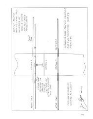
MAJOR ATTACHMENT DETAILS<br />
Some confusion as to "What Fits Where" has resulted from the serialized presentation of FLY<br />
BABY plans in SPORT AVIATION magazine (starting in January, 1963) and the delivery of plans<br />
by chapters to early purchasers. Without a single overall assembly or drawing, or all of the major<br />
section drawings together at one time for comparison, a misunderstanding of the functions of<br />
various parts is inevitable. To offset this, the supplementary drawing presented above has been<br />
prepared to show how and at what points the wing, landing gear, and other components attach to<br />
the fuselage.<br />
<strong>The</strong> wing spars attach to the bottoms of Stations 3 and 5 by means of 1/2" pins passing through<br />
the end fittings and the wood. <strong>The</strong> landing gear vee's attach by means of AN-4-44 bolts at Stations<br />
2 and 4. <strong>The</strong> seat rails of Figure 1-17 are mounted between Stations 4 and 5, and the combined<br />
floor and wing hinge tube supports of Figure 1-18 are between Stations 2 and 3. <strong>The</strong> control stick<br />
torque tube bearing blocks are mounted on the aft side of Station 3 and the front side of Station 4<br />
as shown in Figure 1-17. <strong>The</strong> upper wing wire anchors and the instrument panel are mounted at<br />
the top of Station 3 per Figures 1-20 and 1-21. <strong>The</strong> throttle is mounted through the lower inside<br />
bolt hole of the left-hand wing wire anchors.<br />
End of Fuselage Section<br />
<strong>Page</strong> 1-30