Create successful ePaper yourself
Turn your PDF publications into a flip-book with our unique Google optimized e-Paper software.
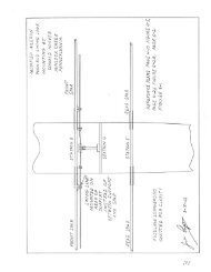
THE PLANS<br />
<strong>The</strong> method of presenting the plans for FLY BABY is quite different from the traditional "Roll of<br />
Blueprints" approach. Instead of a maze of full-size and meticu1ously dimensioned drawings,<br />
most items are presented in reduced scale with accompanying step-by-step pictorial and written<br />
instructions or a single convenient loose-leaf document. <strong>The</strong> isometric drawings are not always to<br />
true scale. In some cases, individual parts are drawn in over-size to emphasize a detail or an<br />
assembly method or undersize to avoid overlap or to fit into the available space. In such cases,<br />
the important dimensions are given.<br />
In recognition of the fact that close tolerances are hard to work to, even without the usual homeworkshop<br />
handicap of inexperience, sub-standard working area, and bare-minimum tooling,<br />
many structural items have been designed with the deliberate intention that their final<br />
dimensions be established by the procedure known as "Fit on Assembly". This eliminates wasted<br />
material and time-consuming rework when inaccuracies, which are not in themselves critical,<br />
prevent two mating parts from fitting together properly Because of this concept, many of the<br />
parts are not dimensioned in as much detail as would ordinarily be expected.<br />
<strong>The</strong> drawings also anticipate certain problems in the procurement of hardware and equipment.<br />
In many cases, sizes for sheet metal or tubular parts are a recommended minimum only. <strong>The</strong><br />
airplane is of such a size that the weight penalty resulting from a change of metal thickness from<br />
1/16" to 3/32" or even 1/8" on these parts is negligible. <strong>The</strong>refore, it is not necessary to spend a<br />
lot of time and effort trying to locate material of the exact specified size when plenty or perfectly<br />
acceptable substitute material may be right at hand.<br />
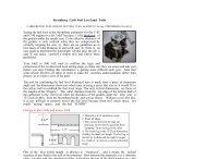
<strong>The</strong> same reasoning also applies to such "used hardware" items as fuel tanks, brakes, and brake<br />
master cylinders. Mechanical brakes are just as suitable as the hydraulic type used on the<br />
prototype FLY BABY. Since there are so many possible combinations of brakes and actuators it<br />
would be pointless to illustrate them all in the drawings. If the builder is too inexperienced in<br />
aircraft practice to determine acceptable part and material substitutions within the general intent<br />
of these drawings, he should, in the absence of experienced neighbors, consult a licensed airframe<br />
mechanic at the nearest airport or a Federal Aviation Agency Safety and Maintenance Inspector<br />
(under U.S. Gov't., Dept. of Transportation, in the telephone directory).<br />
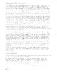
THE WORKING AREA AND CONDITIONS<br />
Building an airplane is not a big job. It is a whole collection of little ones whose degree of<br />
simplicity or difficulty, independent of the builder's skill, is influenced to a large degree by the<br />
available work area and conditions. Airplanes similar to FLY BABY have been built in<br />
surprisingly illogical places, so it can be done without formal shop facilities.<br />
However, suitable space where the work can be left standing is desirable. Since FLY BABY breaks<br />
down to components of convenient size, a standard one-car garage with a work bench across one<br />
end is suitable for the entire job. Minimum area for building the wing is enough to lay the 4-1/2 x<br />
13 foot panel flat at a convenient working level and still allow room to work around each side and<br />
iii