You also want an ePaper? Increase the reach of your titles
YUMPU automatically turns print PDFs into web optimized ePapers that Google loves.
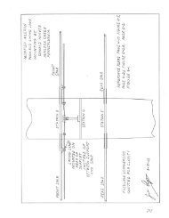
1. Lay three spreader bars on a flat surface, and fit the fuselage sides into them UPSIDE DOWN<br />
as shown in Figure 1-5. Add the two remaining bars to the "Top" with the rear one at Station<br />
5.<br />
2. Square the sides and the front end as shown, and after a double-check of the nose from the<br />
opposite side to be SURE that it is square, tack on two cross-strips of wood aft of Station 6 to<br />
assure the rigidity of the structure.<br />
3. Build up wing support Stations 3 and 5 according to Steps A through D of Figure 1-6. <strong>The</strong><br />
curves for the plywood faces of Step D can be marked to size by notching the straight sections<br />
to fit and then penciling around the corner bows. Be sure to varnish the areas inside the<br />
structure before putting on the second piece of plywood.<br />
4. Landing gear support Stations 2 and 4 are built up the same way except that corner bows are<br />
not used. Do not build in Station 2 until after the firewall is mounted.<br />
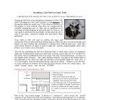
5. <strong>The</strong> shapes and locations of the various 3/h" plywood filler blocks that anchor the Station 2<br />
through 5 cross members to the lower double-longeron structure are determined from the<br />
details of Figure 1-7 as keyed to Figure 1-1. <strong>The</strong> dimensions are not critical, but should not be<br />
less than shown. Note that the blocks at wing support Stations 3 and 5 are notched out 3/16"<br />
to allow the wing fittings to slip through. <strong>The</strong> holes in the rear blocks at Station 3 for the<br />
aileron push rod are a bit under-size at this stage deliberately.<br />
6. Glue the blocks to the outer plywood skin after pressing them tightly against the plywood of<br />
the cross-members per Step E of Figure 1-6.<br />
7. Cut and fit 1/8" plywood to form an inner covering for the double lower longeron structure<br />
per Step F of Figure 1-6. Don't forget to varnish the insides before putting on the plywood,<br />
and then drill a vent hole at the bottom of each closed area. It is best to drill the hole in the<br />
plywood before you put it on.<br />
NOTE<br />
<strong>The</strong> work of Steps 3 through 7, above, results in Box Structure, which should be<br />
inspected and approved by an FAA inspector before being closed up. He may not<br />
insist on it for this particular piece of structure, but it is YOU responsibility to notify<br />
him. Show him the drawings way ahead of time, and you might not be held up at this<br />
point by having to wait for his approval.<br />
[<strong>The</strong> above note is included for historical purposes. <strong>The</strong> FAA no longer requires these kinds of<br />
inspections. RJW]<br />
8. Mark the location of the wing spar pin holes on Stations 3 and 5 per the cross-section views of<br />
Figure 1-9. <strong>The</strong>y can be drilled at this time, but it is a good idea to wait and see if the wings<br />
line up properly.<br />
9. With Stations 3 through 5 in and anchored, the structure is now sufficiently rigid to allow<br />
removal of the spreader bars so that it can be turned over for working at more convenient<br />
angles.<br />
<strong>Page</strong> 1-10