Create successful ePaper yourself
Turn your PDF publications into a flip-book with our unique Google optimized e-Paper software.
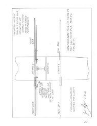
18. Bend up a sheet of .032 steel so that it just fits the tailpost/fuselage intersection. It is held on<br />
each side by three 3/l6" bolts through the outer plywood and the uprights, and through the<br />
tailpost by the two lower hinge bolts and one other as shown in Figure 1-11. Be sure to varnish<br />
the wood under the anchor before installing it, and paint or cadmium plate the anchor. See<br />
Also Figure 1-2, cross-section B-B.<br />
19. Install the 3/4" square cross piece shown 7" ahead of the rudder post on the top longeron<br />
view of Figure 1-8 and Figures 1-11 and 1-12. Note that this is cut half-way through from the<br />
bottom for control cable clearance. Cover the area from the previously-installed cross piece<br />
21" ahead of the rudder post to the rudder post with 1/8" plywood in TWO PIECES, butted<br />
together on the centerline of the 7" crosspiece. <strong>The</strong> purpose of the crosspiece is to stiffen the<br />
plywood ahead of the cutout in the piece of small plywood that is cut out per Figure 1-12 to<br />
allow the elevator horn to protrude through. Nail and glue 1/8" plywood below the lower<br />
longerons from Station 9 to the rudder post AFTER the underfin side plywood anchor stripes<br />
have been nailed and glued in place per Figure 1-13. Drill drain holes in the bottom plywood<br />
at the corners of Stations 9 and II and trim plywood flush with sides of longerons.<br />
20. Build up the underfin structure as shown in Figure 1-13. <strong>The</strong> 1/4" square flanges provide side<br />
surface for the plywood side pieces to be nailed and glued to. Note the cutout at the rear<br />
center of the bottom rib to allow access to the tail spring support bolts that go through the<br />
bottom of the tail post.<br />
FUSELAGE SECONDARY STRUCTURE<br />
<strong>The</strong> secondary fuselage structure consists of those parts added after the main framework has been<br />
assembled per instructions in the earlier portions of this chapter. Since most of these are not<br />
primary load-carrying parts, the builder has great leeway in the use of sizes and materials other<br />
than those specified. <strong>The</strong> "Turtledeck" around and aft of the cockpit (see Section 6) was designed<br />
to be removable and interchangeable with an enclosed-type canopy structure, but either type of<br />
structure can be built on permanently if desired. An item like the forward slope of the instrument<br />
panel is entirely arbitrary. Tall pilots would probably prefer a greater slope while short pilots<br />
would want it more nearly vertical.<br />
1. Cut firewall Former No. 1 from 3/8" plywood per Figure 1-14 and the three top fuselage<br />
formers at Stations 6, 7, and 8 from 1/4" plywood. A strip of wood with a nail as a pivot and a<br />
hole for a pencil makes a good compass to swing long arcs of circles (Figure l-15).<br />
NOTE<br />
<strong>The</strong> lower portion of the No.1 Former on Figure 1-14 is out of scale, so use the<br />
dimensions as written.<br />
<strong>Page</strong> 1-18