
You also want an ePaper? Increase the reach of your titles
YUMPU automatically turns print PDFs into web optimized ePapers that Google loves.
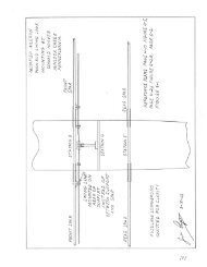
2. Build up a 3/4" wide by 3/4" deep flange on backside of top portion of Former No.1 per<br />
Figures 1-14 and 1-15. <strong>The</strong> only purpose of this is to serve as a base for the nutplates that<br />
anchor the forward metal turtledeck, and can be built up of scraps of 3/4" plywood trimmed<br />
to fit or can be laminated as a single bow by tracing the curve off on a work surface, drawing a<br />
line set inside 3/4", driving nails along it, and laminating strips of 1/l6" x 3/4" wood in place.<br />
3. Glue in Former No.1. After it has set, trim the excess side plywood and install the landing<br />
gear support at Station 2 per Figure 1-6. When installing the inner plywood between Stations<br />
1 and 2, carry the plywood upward along the diagonal per Figure 1-15.<br />
4. Cut a 1/8" x 1-1/2" x 1-1/2" 2024 dural angle, trimmed flush with the top and bottom<br />
longerons, to fit the firewall corners per Figure 1-16. Do not drill or install at this time.<br />
NOTE<br />
If you have difficulty getting dural angle, the weight penalty is negligible if you use 1/8"<br />
mild steel angles easily obtainable from most metal supply stores. An alternate is to bend up<br />
3/32" or 1/8" sheet steel, but this job will probably have to be done at a metal shop where a<br />
22" piece can be bent on a brake.<br />
5. Install Formers 6 through 8 on the BACK SIDES of the 3/4" top across pieces at those<br />
stations, and glue in the six 1/4" x 1" stringers. Don't try to save weight by making the<br />
stringers any thinner. Note from Figure 1-15 that the forward ends are notched to take a<br />
2"strip of 1/8" plywood.<br />
6. Fit the plywood strip to the stringers at Station 6 by laying an over-size strip, GRAIN<br />
PARALLEL TO STRINGERS, in place and marking the forward edge by using the front of<br />
Former 6 as a guide. Measure back 2 inches for the rear line, trim, and install. <strong>The</strong> fabric will<br />
have a smoother appearance if the plywood is scalloped per the dotted lines of Detail A,<br />
Figure 1-15, after installation.<br />
7. Build up box-construction seat support beams and install with triangular glued and nailed<br />
corner blocks per Figure 1-17.<br />
Note positions of rudder cable holes, control stick bearings, and belly stringers for future<br />
reference.<br />
8. Install combined floorboard beams and wing hinge tube supports between Station 2 and 3<br />
per Figure 1-18. <strong>The</strong> holes for the 1" I.D. tube can be drilled any time, but it is easiest to do it<br />
now, before the beams are installed. If the tubes are installed now, be sure to leave the<br />
matching fitting on the wing root undrilled until the wing can be installed on the fuselage and<br />
proper alignment of the tube and the hinge assured.<br />
<strong>Page</strong> 1-20