
You also want an ePaper? Increase the reach of your titles
YUMPU automatically turns print PDFs into web optimized ePapers that Google loves.
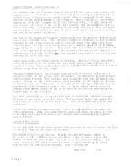
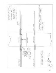
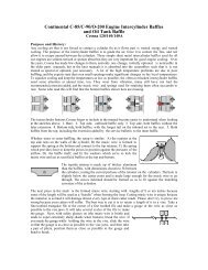
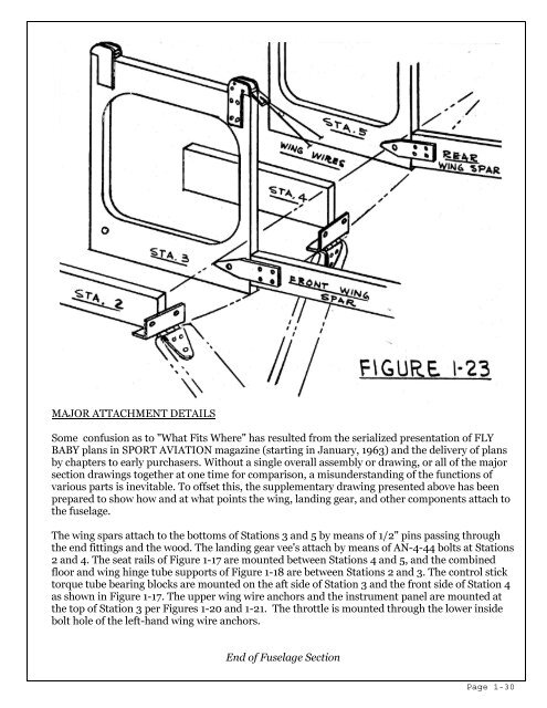
MAJOR ATTACHMENT DETAILS<br />
Some confusion as to "What Fits Where" has resulted from the serialized presentation of FLY<br />
BABY plans in SPORT AVIATION magazine (starting in January, 1963) and the delivery of plans<br />
by chapters to early purchasers. Without a single overall assembly or drawing, or all of the major<br />
section drawings together at one time for comparison, a misunderstanding of the functions of<br />
various parts is inevitable. To offset this, the supplementary drawing presented above has been<br />
prepared to show how and at what points the wing, landing gear, and other components attach to<br />
the fuselage.<br />
<strong>The</strong> wing spars attach to the bottoms of Stations 3 and 5 by means of 1/2" pins passing through<br />
the end fittings and the wood. <strong>The</strong> landing gear vee's attach by means of AN-4-44 bolts at Stations<br />
2 and 4. <strong>The</strong> seat rails of Figure 1-17 are mounted between Stations 4 and 5, and the combined<br />
floor and wing hinge tube supports of Figure 1-18 are between Stations 2 and 3. <strong>The</strong> control stick<br />
torque tube bearing blocks are mounted on the aft side of Station 3 and the front side of Station 4<br />
as shown in Figure 1-17. <strong>The</strong> upper wing wire anchors and the instrument panel are mounted at<br />
the top of Station 3 per Figures 1-20 and 1-21. <strong>The</strong> throttle is mounted through the lower inside<br />
bolt hole of the left-hand wing wire anchors.<br />
End of Fuselage Section<br />
<strong>Page</strong> 1-30