Development of LS-DYNA Occupant Model for Use in Crash ...
Development of LS-DYNA Occupant Model for Use in Crash ...
Development of LS-DYNA Occupant Model for Use in Crash ...

Create successful ePaper yourself
Turn your PDF publications into a flip-book with our unique Google optimized e-Paper software.
Kirkpatrick, et al. 1<br />
<strong>Development</strong> <strong>of</strong> an <strong>LS</strong>-<strong>DYNA</strong> <strong>Occupant</strong> <strong>Model</strong> <strong>for</strong> use <strong>in</strong> <strong>Crash</strong> Analyses <strong>of</strong> Roadside<br />
Safety Features<br />
Steven W. Kirkpatrick, Robert MacNeill, and Robert T. Bocchieri<br />
Applied Research Associates, Inc., 2672 Bayshore Parkway, Suite 1035, Mounta<strong>in</strong> View, Cali<strong>for</strong>nia 94043<br />
Ph. 650-625-8150, Fax 650-625-8145, skirkpatrick@ara.com, rmacneill@ara.com, rbocchieri@ara.com<br />
Paper No. 03-4450<br />
Submitted: August 1, 2002<br />
Revised: November 15, 2002<br />
Word Count: 3,988<br />
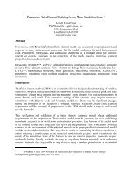
This paper presents the development and validation <strong>of</strong> an <strong>LS</strong>-<strong>DYNA</strong> f<strong>in</strong>ite element occupant model suitable <strong>for</strong> use<br />
<strong>in</strong> crash analyses <strong>of</strong> roadside safety features. The addition <strong>of</strong> an occupant model <strong>in</strong> crash simulations can provide a<br />
l<strong>in</strong>k between vehicle accelerations and occupant <strong>in</strong>jury. Injury measures <strong>for</strong> the vehicle occupants can provide<br />
additional evaluation criteria <strong>for</strong> the effectiveness <strong>of</strong> roadside safety features. The use <strong>of</strong> an occupant model <strong>in</strong><br />
roadside hardware crash analyses will also improve the fidelity <strong>of</strong> the crash analysis by correctly model<strong>in</strong>g the<br />
<strong>in</strong>ertial effects <strong>of</strong> the occupants and their <strong>in</strong>teraction with the vehicle motions.<br />
The approach used here is to construct much <strong>of</strong> the occupant model from rigid bodies connected by jo<strong>in</strong>ts.<br />
The geometry and weight <strong>of</strong> each body segment were obta<strong>in</strong>ed from specifications <strong>of</strong> anthropomorphic test devices<br />
(ATDs) commonly used <strong>in</strong> crash test<strong>in</strong>g. Additional flexible components <strong>of</strong> the occupant model, such as the neck<br />
and sp<strong>in</strong>e, were modeled us<strong>in</strong>g de<strong>for</strong>mable elements with geometry and properties chosen to match those <strong>of</strong> the<br />
ATDs. Us<strong>in</strong>g the correct comb<strong>in</strong>ation <strong>of</strong> de<strong>for</strong>mable and rigid components results <strong>in</strong> an occupant model that is<br />
computationally efficient and capable <strong>of</strong> simulat<strong>in</strong>g occupant k<strong>in</strong>ematics <strong>in</strong> a collision.<br />
INTRODUCTION<br />
There has been an ongo<strong>in</strong>g research program sponsored by the Federal Highway Adm<strong>in</strong>istration (FHWA) to develop<br />
model<strong>in</strong>g tools and advance the use <strong>of</strong> f<strong>in</strong>ite element crash analyses <strong>for</strong> design <strong>of</strong> roadside safety features (1,2). To<br />
assist <strong>in</strong> this ef<strong>for</strong>t, FHWA has developed a series <strong>of</strong> vehicle models that can be used <strong>in</strong> crash analyses. These<br />
vehicle models developed <strong>for</strong> crash analyses with roadside hardware typically have less than 100,000 elements and<br />
allow <strong>for</strong> the longer simulation durations typically required <strong>for</strong> the analysis <strong>of</strong> roadside hardware. These models<br />
have been used by researchers <strong>in</strong> the analysis and development <strong>of</strong> a range <strong>of</strong> roadside safety features such as<br />
guardrails and breakaway lum<strong>in</strong>aire supports (e.g. 3,4).<br />
F<strong>in</strong>ite element analyses <strong>of</strong> roadside hardware crashworth<strong>in</strong>ess have different requirements than analyses<br />
per<strong>for</strong>med <strong>for</strong> vehicle crashworth<strong>in</strong>ess. The primary objectives are to determ<strong>in</strong>e the response <strong>of</strong> a roadside safety<br />
feature to impact and the result<strong>in</strong>g vehicle motions, as opposed to the detailed crush response <strong>of</strong> the vehicle. S<strong>in</strong>ce<br />
the post collision motions <strong>of</strong> the vehicle are important to the analysis, the duration <strong>of</strong> the collision event can be<br />
many times longer than a vehicle-to-vehicle collision or frontal impact <strong>in</strong>to a fixed barrier. The major role <strong>of</strong> many<br />
roadside longitud<strong>in</strong>al barriers dur<strong>in</strong>g an impact is to redirect the vehicle smoothly back <strong>in</strong> the direction <strong>of</strong> travel and<br />
to discourage vehicle motions that would result <strong>in</strong> a vehicle rollover or uncontrollable redirection <strong>in</strong>to the traffic<br />
flow. An additional goal <strong>of</strong> roadside safety features is to produce a load distribution on the vehicle that does not<br />
result <strong>in</strong> vehicle de<strong>for</strong>mations <strong>in</strong> the occupant compartment.<br />
Most crash analyses <strong>of</strong> roadside safety features have been per<strong>for</strong>med without model<strong>in</strong>g <strong>of</strong> the occupants.<br />
The effectiveness <strong>of</strong> these safety features have been primarily evaluated based on the crash k<strong>in</strong>ematics and<br />
de<strong>for</strong>mations <strong>of</strong> the vehicle and roadside hardware. Direct measures <strong>of</strong> the crash response <strong>of</strong> occupants have not<br />
been used to evaluate the effectiveness <strong>of</strong> a roadside safety feature. Instead, secondary risk measures <strong>for</strong> occupants<br />
are evaluated such as occupant compartment <strong>in</strong>trusion and vehicle ride down acceleration. Us<strong>in</strong>g this analysis<br />
approach, an estimate <strong>of</strong> the severity <strong>of</strong> occupant secondary impacts with the vehicle <strong>in</strong>terior can be obta<strong>in</strong>ed.<br />
However, this approach can not accurately assess the <strong>in</strong>teraction <strong>of</strong> the occupants with the vehicle <strong>in</strong>terior and crash<br />
safety features such as restra<strong>in</strong>ts, crash padd<strong>in</strong>g, and airbags.<br />
Recently, there has been <strong>in</strong>terest <strong>in</strong> the development and application <strong>of</strong> an occupant model <strong>in</strong> roadside crash<br />
analysis to improve the l<strong>in</strong>k between vehicle accelerations and occupant response and <strong>in</strong>jury. Includ<strong>in</strong>g occupant<br />
TRB 2003 Annual Meet<strong>in</strong>g CD-ROM<br />
Paper revised from orig<strong>in</strong>al submittal.
Kirkpatrick, et al. 2<br />
models <strong>in</strong> crash simulations would be helpful <strong>in</strong> both correctly model<strong>in</strong>g the <strong>in</strong>ertial effects <strong>of</strong> the occupants <strong>in</strong> the<br />
collision and provid<strong>in</strong>g additional <strong>in</strong><strong>for</strong>mation about the potential <strong>for</strong> <strong>in</strong>jury <strong>of</strong> the occupants. This document<br />
describes the development <strong>of</strong> a f<strong>in</strong>ite element occupant model that can be used <strong>in</strong> crash analyses <strong>of</strong> roadside safety<br />
features. The occupant model uses a comb<strong>in</strong>ation <strong>of</strong> simple rigid body k<strong>in</strong>ematics model<strong>in</strong>g and detailed model<strong>in</strong>g<br />
<strong>of</strong> anthropomorphic test device (ATD) components. The occupant model development takes advantage <strong>of</strong> the<br />
previous development <strong>of</strong> ATDs and ATD components as human surrogates.<br />
Several f<strong>in</strong>ite element models <strong>of</strong> occupants or ATDs have been developed with vary<strong>in</strong>g degrees <strong>of</strong><br />
bi<strong>of</strong>idelity. For example, models <strong>of</strong> the Part 572 Subpart B Side Impact Dummy (e.g., the SID) have been<br />
developed and applied <strong>for</strong> analysis <strong>of</strong> various crashworth<strong>in</strong>ess problems. These <strong>in</strong>clude both proprietary models<br />
developed by automobile manufacturers (5,6) and models developed under sponsorship <strong>of</strong> the U.S. Department <strong>of</strong><br />
transportation (7,8). These detailed f<strong>in</strong>ite element models <strong>of</strong> ATDs <strong>in</strong>clude descriptions <strong>of</strong> the mechanical<br />
components that make up the ATD structure such as the ribs, sp<strong>in</strong>e box, rubber neck and lower sp<strong>in</strong>e, <strong>in</strong>ternal rib<br />
damper, foam padd<strong>in</strong>g, abdom<strong>in</strong>al <strong>in</strong>sert, and outer rubber jacket. An additional level <strong>of</strong> occupant model<strong>in</strong>g with<br />
potentially the highest level <strong>of</strong> bi<strong>of</strong>idelity is to model the correct anatomic structures <strong>of</strong> the human. An example <strong>of</strong><br />
this approach is the Total Human <strong>Model</strong> <strong>for</strong> Safety (THUMS) described <strong>in</strong> Reference 9. Several additional<br />
anatomic human models exist <strong>for</strong> various body components. An example is the f<strong>in</strong>ite element model <strong>of</strong> the human<br />
anatomic pelvis and leg developed under a NHTSA sponsored program (10). This type <strong>of</strong> model could be applied to<br />
study lower extremity <strong>in</strong>juries <strong>in</strong> vehicle frontal collisions. All <strong>of</strong> these detailed models can be useful to analyze and<br />
help develop improved tools <strong>for</strong> occupant protection systems. However, these models can be very complex and<br />
computationally demand<strong>in</strong>g. A more computationally efficient model is needed <strong>for</strong> use <strong>in</strong> crash analyses <strong>of</strong> roadside<br />
safety features.<br />
OCCUPANT MODEL DEVELOPMENT<br />
Simulations <strong>of</strong> vehicle collisions with roadside safety features can have large computational requirements. As a<br />
result, an occupant model <strong>for</strong> this application should not significantly <strong>in</strong>crease the computational requirements or<br />
control the m<strong>in</strong>imum time step. There<strong>for</strong>e, the model must be computationally efficient and easy to <strong>in</strong>corporate <strong>in</strong>to<br />
exist<strong>in</strong>g vehicle models. The occupant model adapted <strong>in</strong> this ef<strong>for</strong>t is based on a <strong>DYNA</strong>3D model orig<strong>in</strong>ally<br />
developed <strong>for</strong> analysis <strong>of</strong> occupants <strong>in</strong> a tra<strong>in</strong> collision (11,12). The result<strong>in</strong>g occupant model is shown <strong>in</strong> Figure 1.<br />
The model<strong>in</strong>g approach adapted <strong>in</strong> this ef<strong>for</strong>t was to construct the majority <strong>of</strong> the occupant model from rigid bodies<br />
connected by jo<strong>in</strong>ts. A sketch <strong>of</strong> an example rotational jo<strong>in</strong>t configuration <strong>for</strong> the ankle is shown <strong>in</strong> Figure 2. Rigid<br />
body jo<strong>in</strong>t blocks <strong>in</strong> the lower leg and foot are used to def<strong>in</strong>e the jo<strong>in</strong>t constra<strong>in</strong>t. Nonl<strong>in</strong>ear spr<strong>in</strong>gs and dampers<br />
were <strong>in</strong>cluded <strong>in</strong> the jo<strong>in</strong>t def<strong>in</strong>itions to control the range <strong>of</strong> motions and appropriate rotational resistance. The<br />
nonl<strong>in</strong>ear spr<strong>in</strong>g characteristics are determ<strong>in</strong>ed based on the <strong>in</strong>itial angle <strong>of</strong> the jo<strong>in</strong>t. Other jo<strong>in</strong>ts <strong>in</strong> the extremities<br />
<strong>of</strong> the occupant model are def<strong>in</strong>ed us<strong>in</strong>g the same methodology. As def<strong>in</strong>ed, the jo<strong>in</strong>t model<strong>in</strong>g does not allow <strong>for</strong><br />
failure or assessment <strong>of</strong> <strong>in</strong>jury measures at the jo<strong>in</strong>ts. This model<strong>in</strong>g <strong>of</strong> the occupant arms and legs is similar <strong>in</strong><br />
approach to the rigid body k<strong>in</strong>ematics models such as the Articulated Total Body (ATB) model or MADYMO.<br />
The current version <strong>of</strong> the occupant model is created to model the response <strong>of</strong> seated occupants only. This<br />
is similar to the configuration <strong>of</strong> typical ATDs used <strong>in</strong> crash test<strong>in</strong>g. The geometry <strong>of</strong> the pelvis, hips, and upper<br />
legs does not allow a sufficient range <strong>of</strong> motion <strong>for</strong> the occupant to reach an upright stand<strong>in</strong>g position. In the<br />
occupant model, a spherical jo<strong>in</strong>t is def<strong>in</strong>ed at the connection <strong>of</strong> the upper leg/femur rigid component and the<br />
hip/pelvis rigid component. A section <strong>of</strong> de<strong>for</strong>mable s<strong>of</strong>t tissue or foam material <strong>in</strong> the upper portion <strong>of</strong> the thigh<br />
connect<strong>in</strong>g the pelvis and upper leg allows <strong>for</strong> flexibility <strong>of</strong> the hip jo<strong>in</strong>t while limit<strong>in</strong>g the range <strong>of</strong> motion. This<br />
model<strong>in</strong>g approach was based on a similar geometry used <strong>in</strong> the construction <strong>of</strong> ATDs.<br />
This new occupant model differs from the rigid body k<strong>in</strong>ematics models <strong>in</strong> the model<strong>in</strong>g approach <strong>for</strong> the<br />
abdomen, lower sp<strong>in</strong>e, head, and neck. The head and neck behavior is obta<strong>in</strong>ed by <strong>in</strong>clud<strong>in</strong>g a de<strong>for</strong>mable model <strong>of</strong><br />
a rubber anthropomorphic test device (ATD) neck. Similarly, de<strong>for</strong>mable ATD lower sp<strong>in</strong>e and abdom<strong>in</strong>al <strong>in</strong>sert<br />
components are <strong>in</strong>cluded <strong>in</strong> the model to control the motions <strong>of</strong> the thorax. Us<strong>in</strong>g this limited set <strong>of</strong> de<strong>for</strong>mable<br />
ATD components with the rigid components <strong>for</strong> the bulk <strong>of</strong> the occupant resulted <strong>in</strong> a model that is computationally<br />
efficient and capable <strong>of</strong> reproduc<strong>in</strong>g ATD or occupant k<strong>in</strong>ematics with sufficient fidelity.<br />
The Dummy model conta<strong>in</strong>s approximately 3100 de<strong>for</strong>mable hexahedral brick elements and the rema<strong>in</strong>der<br />
<strong>of</strong> the occupant model is lumped <strong>in</strong>to 15 rigid body def<strong>in</strong>itions. The de<strong>for</strong>mable components are composed <strong>of</strong><br />
relatively s<strong>of</strong>t materials and result <strong>in</strong> a stable time step <strong>for</strong> the occupant model <strong>of</strong> approximately 8 microseconds.<br />
This time step is sufficiently large that it would not be a limit<strong>in</strong>g factor <strong>in</strong> roadside hardware crash simulations. A<br />
TRB 2003 Annual Meet<strong>in</strong>g CD-ROM<br />
Paper revised from orig<strong>in</strong>al submittal.
Kirkpatrick, et al. 3<br />
comparable detailed f<strong>in</strong>ite element model <strong>of</strong> an ATD (e.g. 7, 8) has on the order <strong>of</strong> 20,000 de<strong>for</strong>mable elements and<br />
a time step size <strong>of</strong> approximately one microsecond produced by <strong>in</strong>ternal steel components such as the rib bars. As a<br />
result, the detailed ATD model<strong>in</strong>g approach requires more than an order <strong>of</strong> magnitude more computational time than<br />
the occupant model developed <strong>in</strong> this study.<br />
The current version <strong>of</strong> the occupant model was developed us<strong>in</strong>g the TrueGrid preprocessor code (13).<br />
Many <strong>of</strong> the model features are parameterized to facilitate position<strong>in</strong>g <strong>of</strong> the occupant <strong>in</strong>to a specific seat<strong>in</strong>g<br />
configuration or scal<strong>in</strong>g the model to adjust occupant size. The model is constructed entirely us<strong>in</strong>g the available<br />
features with<strong>in</strong> <strong>LS</strong>-<strong>DYNA</strong> (14) and no additional s<strong>of</strong>tware or code development is required <strong>for</strong> the use <strong>of</strong> the model.<br />
There<strong>for</strong>e, this model is compatible with typical roadside crash analysis methods and can be easily implemented <strong>in</strong><br />
the <strong>LS</strong>-<strong>DYNA</strong> vehicle models.<br />
The geometry and weight <strong>of</strong> each body segment were obta<strong>in</strong>ed from specifications <strong>of</strong> ATD components. In<br />
particular, the various body component <strong>in</strong>ertial properties were created to match those <strong>of</strong> the 50% male Hybrid III<br />
dummy. Additional models were created <strong>for</strong> the 5% female and 95% male dummies by scal<strong>in</strong>g <strong>of</strong> the occupant<br />
model. However, ef<strong>for</strong>ts to calibrate and validate the occupant model have primarily been per<strong>for</strong>med <strong>for</strong> the 50%<br />
male.<br />
An example application <strong>of</strong> the occupant model is the design <strong>of</strong> a commuter tra<strong>in</strong> seat <strong>in</strong>corporat<strong>in</strong>g lap and<br />
shoulder belts, as shown <strong>in</strong> Figure 3. This is an application where a relatively simple occupant model is sufficient.<br />
The primary objective was to create a seat design that was capable <strong>of</strong> support<strong>in</strong>g the maximum expected loads <strong>in</strong> a<br />
collision. The requirement <strong>of</strong> the occupant model is to provide a reasonable estimate <strong>of</strong> the occupant <strong>in</strong>ertial loads<br />
when subjected to a collision acceleration pulse. The simulation shown <strong>in</strong> Figure 3 is <strong>for</strong> three restra<strong>in</strong>ed 95% male<br />
occupants <strong>in</strong> the <strong>for</strong>ward seat and three unrestra<strong>in</strong>ed 95% occupants <strong>in</strong> the rear seat. This comb<strong>in</strong>ation produces the<br />
largest possible occupant load<strong>in</strong>g on the seat frame from the six large male occupants.<br />
In addition to develop<strong>in</strong>g a seat frame capable <strong>of</strong> support<strong>in</strong>g the collision loads, variations <strong>in</strong> the seat<br />
padd<strong>in</strong>g were evaluated to m<strong>in</strong>imize head <strong>in</strong>juries. There<strong>for</strong>e, the occupant model needed to be able to simulate the<br />
crash responses that can be compared to <strong>in</strong>jury criteria. This would be true <strong>in</strong> many crash analysis applications. As<br />
a result, the fidelity <strong>of</strong> the head and neck components is important <strong>for</strong> the utility <strong>of</strong> the occupant model. <strong>Model</strong><strong>in</strong>g<br />
the de<strong>for</strong>mable ATD neck components provides a simple method <strong>of</strong> reproduc<strong>in</strong>g appropriate head and neck<br />
behaviors <strong>in</strong> the occupant model.<br />
OCCUPANT MODEL VALIDATION<br />
Validation <strong>of</strong> the occupant model is important <strong>for</strong> it to be applied <strong>in</strong> crashworth<strong>in</strong>ess research. The approach used to<br />
validate the model is to compare it to experiments per<strong>for</strong>med on ATDs or ATD components. The most important<br />
capability to be validated is the ability <strong>of</strong> the model to reproduce the ATD k<strong>in</strong>ematics under a variety <strong>of</strong> collision<br />
loads. In addition, it is desirable to validate the head and neck components <strong>of</strong> the model due to the importance <strong>of</strong><br />
head and neck <strong>in</strong>juries <strong>for</strong> many crash applications.<br />
Two different test<strong>in</strong>g configurations have been used to validate the occupant model. The first uses a<br />
pendulum calibration test configuration to validate the head and neck components. The second uses a rigid-seat sled<br />
test to validate the model k<strong>in</strong>ematics <strong>for</strong> a frontal load<strong>in</strong>g <strong>of</strong> a restra<strong>in</strong>ed dummy. These validation ef<strong>for</strong>ts are<br />
described below.<br />
Head and Neck <strong>Model</strong> Calibration<br />
The behavior <strong>of</strong> the head and neck system is very important <strong>for</strong> assess<strong>in</strong>g occupant response and <strong>in</strong>jury potential <strong>in</strong><br />
collisions. There<strong>for</strong>e, a series <strong>of</strong> f<strong>in</strong>ite element calculations were per<strong>for</strong>med to simulate the neck bend<strong>in</strong>g calibration<br />
test used to check the k<strong>in</strong>ematic per<strong>for</strong>mance <strong>of</strong> the neck <strong>in</strong> anthropomorphic test devices (ATDs). The neck<br />
bend<strong>in</strong>g calibration test and ATD neck per<strong>for</strong>mance guidel<strong>in</strong>es were obta<strong>in</strong>ed from Reference 15. The test consists<br />
<strong>of</strong> mount<strong>in</strong>g the neck and head<strong>for</strong>m on a pendulum and dropp<strong>in</strong>g it from a height to obta<strong>in</strong> an impact velocity<br />
between 21.5 to 25.5 feet per second (fps). The pendulum is then decelerated at approximately 20 g with a duration<br />
<strong>of</strong> approximately 30 ms . The resultant rotation <strong>of</strong> the head and neck chordal displacement are then measured and<br />
checked aga<strong>in</strong>st the acceptable per<strong>for</strong>mance corridors. Additional <strong>in</strong><strong>for</strong>mation on neck per<strong>for</strong>mance criteria and<br />
test<strong>in</strong>g <strong>of</strong> mechanical, cadaver and volunteer subject necks is available <strong>in</strong> References 16 through 19.<br />
In prelim<strong>in</strong>ary calculations, both the Blatz-Ko rubber and viscoelastic constitutive models were evaluated<br />
<strong>for</strong> the rubber neck section. Handbook values were used to establish basel<strong>in</strong>e material properties and variations <strong>in</strong><br />
TRB 2003 Annual Meet<strong>in</strong>g CD-ROM<br />
Paper revised from orig<strong>in</strong>al submittal.
Kirkpatrick, et al. 4<br />
properties were evaluated to optimize the neck model per<strong>for</strong>mance. These calculations found that a viscoelastic<br />
constitutive model is needed to match both the displacement and rotation criteria <strong>in</strong> the pendulum calibration test.<br />
The comparisons <strong>of</strong> the model predictions with the displacement and rotation qualification corridors are shown <strong>in</strong><br />
Figure 4. The comparison shows good agreement <strong>of</strong> the model with the ATD head and neck per<strong>for</strong>mance criteria.<br />
<strong>Occupant</strong> K<strong>in</strong>ematics Validation<br />
A search <strong>of</strong> the literature was per<strong>for</strong>med to identify an appropriate experiment that could be used <strong>for</strong> validation <strong>of</strong><br />
the dummy model. The experiment configuration selected <strong>for</strong> the dummy model validation was a rigid sled test<br />
(20). These tests have an advantage <strong>of</strong> a rigid seat that does not de<strong>for</strong>m dur<strong>in</strong>g the deceleration load<strong>in</strong>g and,<br />
there<strong>for</strong>e, does not <strong>in</strong>fluence the dummy response. There<strong>for</strong>e, a complex model <strong>of</strong> the seat<strong>in</strong>g system is not required<br />
as part <strong>of</strong> the validation ef<strong>for</strong>t.<br />
A model <strong>of</strong> the rigid sled test configuration was developed and validation calculations were per<strong>for</strong>med.<br />
The model <strong>in</strong>cludes both the rigid sled and seat and lap and shoulder belts to restra<strong>in</strong> the dummy. The dummy used<br />
<strong>in</strong> the test series was the 50% male Hybrid III dummy. The geometry <strong>of</strong> the model <strong>for</strong> the rigid sled test validation<br />
is shown <strong>in</strong> Figure 5. The size and weight <strong>of</strong> the occupant model shown <strong>in</strong> Figure 5 correspond to those <strong>of</strong> the 50%<br />
male dummy.<br />
The load<strong>in</strong>g was a 96 ms deceleration pulse with a peak value <strong>of</strong> approximately 27-g as shown <strong>in</strong> Figure 6.<br />
This acceleration pulse results <strong>in</strong> an approximately 34-mph change <strong>in</strong> velocity <strong>of</strong> the sled. The idealized restra<strong>in</strong>t<br />
system was modeled us<strong>in</strong>g l<strong>in</strong>ear elastic behavior <strong>in</strong> webb<strong>in</strong>g and the ends <strong>of</strong> the restra<strong>in</strong>ts rigidly attached to the<br />
sled. The result<strong>in</strong>g approximations result <strong>in</strong> a calculated peak belt load that is approximately 10% higher than<br />
measured <strong>in</strong> the tests. The calculated response <strong>of</strong> the dummy <strong>in</strong> the rigid sled experiment is shown <strong>in</strong> Figure 7. The<br />
belt resists the <strong>for</strong>ward motion <strong>of</strong> the dummy relative to the seat. The head is bent <strong>for</strong>ward and down as a result <strong>of</strong><br />
the load<strong>in</strong>g pulse and the arms flail upward. These qualitative behaviors were observed <strong>for</strong> the dummies used <strong>in</strong> the<br />
rigid sled tests.<br />
The calculated head and chest accelerations are compared to the measured Hybrid III dummy response<br />
corridors <strong>in</strong> Figure 8. The comparisons show good agreement between the calculated and measured dummy<br />
responses. Some m<strong>in</strong>or discrepancy is observed <strong>for</strong> the early portion <strong>of</strong> the crash pulse. Dur<strong>in</strong>g the <strong>in</strong>itial 40 ms <strong>of</strong><br />
the crash pulse the model under predicts the occupant accelerations measured <strong>in</strong> the sled tests. We believe that this<br />
is due to the model<strong>in</strong>g <strong>of</strong> the lap and shoulder restra<strong>in</strong>ts that did not <strong>in</strong>clude an <strong>in</strong>itial tensile load. With the<br />
exception <strong>of</strong> this <strong>in</strong>itial discrepancy, the model closely reproduces the measured head and chest accelerations.<br />
SUMMARY AND CONCLUSIONS<br />
An occupant model was developed <strong>for</strong> crash analyses us<strong>in</strong>g the <strong>LS</strong>-<strong>DYNA</strong> f<strong>in</strong>ite element code. The model was<br />
created us<strong>in</strong>g a comb<strong>in</strong>ation <strong>of</strong> rigid bodies, jo<strong>in</strong>ts, and de<strong>for</strong>mable ATD components. This comb<strong>in</strong>ation <strong>of</strong><br />
model<strong>in</strong>g techniques provided a model that is computationally efficient. Initial validation calculations demonstrate<br />
the capability <strong>of</strong> the occupant model to simulate collision responses <strong>of</strong> ATDs.<br />
The model has been validated aga<strong>in</strong>st the measured head and chest accelerations <strong>for</strong> a 50% hybrid III<br />
dummy <strong>in</strong> a rigid seat sled test. In addition, limited application <strong>of</strong> the model <strong>for</strong> the evaluation and design <strong>of</strong> tra<strong>in</strong><br />
seat systems has been effective. The de<strong>for</strong>mable neck, lower sp<strong>in</strong>e, and abdom<strong>in</strong>al <strong>in</strong>sert components have<br />
previously been used with<strong>in</strong> a detailed model <strong>of</strong> an ATD and partially validated <strong>for</strong> limited impact conditions (7, 8).<br />
Additional validation <strong>of</strong> the model would be helpful <strong>for</strong> improv<strong>in</strong>g confidence <strong>in</strong> <strong>in</strong>jury measures obta<strong>in</strong>ed by crash<br />
simulations.<br />
F<strong>in</strong>ally, the occupant model shows potential <strong>for</strong> use <strong>in</strong> crash analyses <strong>of</strong> roadside safety features. This<br />
computationally efficient model is ideally suited <strong>for</strong> use <strong>in</strong> roadside crash analysis that <strong>of</strong>ten require relatively long<br />
duration simulations and there<strong>for</strong>e have large computational requirements. The stability requirements <strong>for</strong> the<br />
occupant model will not limit the time step <strong>in</strong> roadside crash simulations. Us<strong>in</strong>g the occupant model <strong>in</strong> roadside<br />
crash analyses will improve the l<strong>in</strong>k between the vehicle accelerations and estimates <strong>of</strong> occupant <strong>in</strong>jury. In addition,<br />
the model can be used to <strong>in</strong>vestigate the <strong>in</strong>ertial effects <strong>of</strong> the occupants on the calculated vehicle crash response.<br />
TRB 2003 Annual Meet<strong>in</strong>g CD-ROM<br />
Paper revised from orig<strong>in</strong>al submittal.
Kirkpatrick, et al. 5<br />
FUTURE MODEL DEVELOPMENT<br />
One <strong>of</strong> the primary concerns <strong>for</strong> future development <strong>of</strong> the occupant model is additional calibration and validation<br />
work. Particular tasks <strong>in</strong>clude: (1) calibration <strong>of</strong> the various jo<strong>in</strong>t def<strong>in</strong>itions to confirm the accurate simulation <strong>of</strong><br />
the range <strong>of</strong> motion and resist<strong>in</strong>g <strong>for</strong>ces under a variety <strong>of</strong> load<strong>in</strong>g conditions, and (2) validation <strong>of</strong> the full occupant<br />
model <strong>for</strong> additional test configurations. Of particular <strong>in</strong>terest <strong>for</strong> roadside crash analysis is validation <strong>of</strong> the model<br />
<strong>for</strong> oblique and side impact test conditions.<br />
Another area <strong>of</strong> model development is to expand the range <strong>of</strong> occupant types that can be represented by the<br />
model. The model was primarily developed and validated <strong>for</strong> the 50% male hybrid III dummy. <strong>Development</strong> and<br />
validation <strong>of</strong> similar occupant models <strong>for</strong> the 5% female and 95% male occupants is desirable. However, suitable<br />
test data <strong>for</strong> validation <strong>of</strong> ATDs beyond the 50% male hybrid III dummy is limited.<br />
F<strong>in</strong>ally, the utility <strong>of</strong> the occupant model needs to be demonstrated <strong>in</strong> roadside crash simulations. In many<br />
cases, this will require creation and/or modification <strong>of</strong> vehicle seat, restra<strong>in</strong>t system, and <strong>in</strong>terior components <strong>in</strong> the<br />
exist<strong>in</strong>g vehicle models (e.g. 21). Subsequent crash simulations can be per<strong>for</strong>med both with and without the<br />
occupant model to <strong>in</strong>vestigate the effect on vehicle response and evaluate the additional computational requirements<br />
<strong>of</strong> the occupant <strong>in</strong> the simulation. Ideally, the collision conditions to be analyzed should be <strong>for</strong> crash tests <strong>in</strong>clud<strong>in</strong>g<br />
<strong>in</strong>strumented ATDs that can be compared to the calculated occupant response.<br />
ACKNOWLEDGEMENTS<br />
Much <strong>of</strong> the work described <strong>in</strong> this paper was per<strong>for</strong>med under various Department <strong>of</strong> Transportation contracts. In<br />
particular, we wish to acknowledge the Volpe National Transportation Systems Center (VNTSC), per<strong>for</strong>m<strong>in</strong>g<br />
research as part <strong>of</strong> the Equipment Safety Research Program sponsored by the Federal Railroad Adm<strong>in</strong>istration<br />
(FRA). The contracts through the VNTSC were <strong>in</strong>itiated and monitored by David Tyrell and Krist<strong>in</strong>e Severson <strong>in</strong><br />
the Structures and Dynamics Division. Tom Tsai, Program Manager, Equipment and Operat<strong>in</strong>g Practices Research<br />
Division, FRA, manages the passenger rail equipment crashworth<strong>in</strong>ess research. Earlier developments <strong>of</strong> f<strong>in</strong>ite<br />
element ATD models were sponsored as a part <strong>of</strong> FHWA and NHTSA research programs. The projects received<br />
valuable assistance and technical direction from Mr. Mart<strong>in</strong> Hargrave <strong>of</strong> the FHWA and Ms. Randa Samaha and Mr.<br />
Thomas Trella <strong>of</strong> the NHTSA. The authors wish to thank these people <strong>for</strong> their generous support and assistance <strong>in</strong><br />
mak<strong>in</strong>g this work possible.<br />
REFERENCES<br />
1. M.H. Ray, “Us<strong>in</strong>g F<strong>in</strong>ite Element Analysis <strong>in</strong> Design<strong>in</strong>g Roadside Hardware,” <strong>in</strong> Public Roads, Vol. 57, No. 4,<br />
Federal Highway Adm<strong>in</strong>istration, Wash<strong>in</strong>gton, D.C., Spr<strong>in</strong>g, 1994.<br />
2. M.W. Hargrave and D. Smith, “Us<strong>in</strong>g the Computer and <strong>DYNA</strong>3D to Save Lives,” Public Roads<br />
http://www.tfhrc.gov/pubrds/janfeb01/us<strong>in</strong>g.htm, January/February 2001. Accessed August 1, 2002.<br />
3. A. Abu-Odeh and R.P. Bligh, “Side Impact Investigations <strong>of</strong> a Slip Base Lum<strong>in</strong>aire Pole,” Proceed<strong>in</strong>gs <strong>of</strong> the<br />
Fourteenth Eng<strong>in</strong>eer<strong>in</strong>g Mechanics Conference, American Society <strong>of</strong> Civil Eng<strong>in</strong>eers, May 21-24, 2000.<br />
4. W. Udd<strong>in</strong> and R.M. Hackett, “Three-Dimensional F<strong>in</strong>ite Element <strong>Model</strong><strong>in</strong>g <strong>of</strong> Vehicle <strong>Crash</strong>es Aga<strong>in</strong>st<br />
Roadside Safety Barriers,” Presented at the International <strong>Crash</strong>worth<strong>in</strong>ess Conference IJ<strong>Crash</strong>’98, September 9-<br />
11, 1998, pp. 573-583.<br />
5. D. E. Midoun, E. Abramoski, M.K. Rao & R. Kalid<strong>in</strong>di, “<strong>Development</strong> <strong>of</strong> a F<strong>in</strong>ite Element Based <strong>Model</strong> <strong>of</strong> the<br />
Side Impact Dummy,” SAE Paper No. 930444, (1993).<br />
6. H. Motojima, J. Hasegawa, Y. Ogawa, K. Ando and E. Haug, “<strong>Development</strong> <strong>of</strong> a F<strong>in</strong>ite Element <strong>Model</strong> <strong>of</strong> the<br />
Side Impact Dummy and Application <strong>for</strong> the Side Impact Protection,” Toyota Technical Review, Vol. 46, No.<br />
2, pp. 25-31, Apr. 1997.<br />
7. S.W. Kirkpatrick, B.S. Holmes, T.C. Hollowell, C. Gabler, and T. Trella, “F<strong>in</strong>ite Element <strong>Model</strong><strong>in</strong>g <strong>of</strong> the Side<br />
Impact Dummy (SID),” Human Surrogates: Design, <strong>Development</strong>, & Side Impact Protection, SAE<br />
Publications, SP-945, pp. 75-86, Presented at the 1993 International Congress and Exposition, March, 1993,<br />
SAE Paper No. 930104, (1993).<br />
TRB 2003 Annual Meet<strong>in</strong>g CD-ROM<br />
Paper revised from orig<strong>in</strong>al submittal.
Kirkpatrick, et al. 6<br />
8. M.H. Ray, K. Hiranmayee, and S.W. Kirkpatrick, “Per<strong>for</strong>mance Validation <strong>of</strong> Two F<strong>in</strong>ite Element <strong>Model</strong>s <strong>of</strong> a<br />
Side Impact Dummy,” International Journal <strong>of</strong> <strong>Crash</strong>worth<strong>in</strong>ess, IJ<strong>Crash</strong> Vol. 4, No. 3, pp. 287-303, 1999.<br />
9. J. Hasegawa and T. Maeno, "<strong>Development</strong> <strong>of</strong> a F<strong>in</strong>ite Element <strong>Model</strong> <strong>of</strong> the Total Human <strong>Model</strong> <strong>for</strong> Safety<br />
(THUMS) and Application to Car-Pedestrian Impacts", 17th ESV Conference, (2001), Paper No. 494.<br />
10. D.A. Schaur, S.A. Perfect, and J.A. Weiss, “F<strong>in</strong>ite Element <strong>Model</strong><strong>in</strong>g <strong>of</strong> the Human Anatomic Pelvis and Leg,”<br />
NHTSA Draft F<strong>in</strong>al Report, July 1997.<br />
11. S.W. Kirkpatrick, M. Schroeder, and J.W. Simons, “Evaluation <strong>of</strong> Passenger Rail Vehicle <strong>Crash</strong>worth<strong>in</strong>ess,”<br />
International Journal <strong>of</strong> <strong>Crash</strong>worth<strong>in</strong>ess, IJ<strong>Crash</strong> Vol. 6 No. 1 pp. 95-106, 2001.<br />
12. J.W. Simons and S.W. Kirkpatrick, “High-Speed Passenger Tra<strong>in</strong> <strong>Crash</strong>worth<strong>in</strong>ess and <strong>Occupant</strong><br />
Survivability,” International Journal <strong>of</strong> <strong>Crash</strong>worth<strong>in</strong>ess, IJ<strong>Crash</strong> Vol. 4, No. 2, pp. 121-132, 1999.<br />
13. "TrueGrid Manual, Version 2.1.0," XYZ Scientific Applications, Inc., September 7, 2001.<br />
14. “<strong>LS</strong>-<strong>DYNA</strong> <strong>Use</strong>r’s Manual: Nonl<strong>in</strong>ear Dynamic Analysis <strong>of</strong> Structures <strong>in</strong> Three Dimensions,” Livermore<br />
S<strong>of</strong>tware Technology Corporation, Version 950, May 1999.<br />
15. USDOT NHTSA Laboratory Test Procedure <strong>for</strong> FMVSS No. 214 “Side Impact Protection - Passenger Cars.”<br />
16. H.J. Mertz, R.F. Neathery, & C.C. Culver, "Per<strong>for</strong>mance Requirements and Characteristics <strong>of</strong> Mechanical<br />
Necks," Human Impact Response Measurement & Simulation, A.I K<strong>in</strong>g & H.J. Mertz Eds., Plenum Press, 1973.<br />
17. K.H. Yang, & J. Le, "F<strong>in</strong>ite Element <strong>Model</strong><strong>in</strong>g <strong>of</strong> Hybrid III Head-Neck Complex," SAE Paper No. 922526,<br />
Proceed<strong>in</strong>gs 36 th Stapp Car <strong>Crash</strong> Conference, 1992.<br />
18. J. Wismans, H. van Oorschot, & H.J. Woltr<strong>in</strong>g, "Omni-Directional Human Head Neck Response," Proceed<strong>in</strong>gs<br />
30 th Stapp Car <strong>Crash</strong> Conference, SAE Paper No. 861893, pp. 313-331, October 1986.<br />
19. M.R. Seemann, W.H. Muzzy III, & L.S. Lustick, "Comparison <strong>of</strong> Human and Hybrid III Head and Neck<br />
Dynamic Response," Proceed<strong>in</strong>gs 30 th Stapp Car <strong>Crash</strong> Conference, SAE Paper 861892, pp. 291-311, October<br />
1986.<br />
20. P. Prasad, “Comparative Evaluation <strong>of</strong> the Dynamic Responses <strong>of</strong> the Hybrid II and Hybrid III Dummies,”<br />
Proceed<strong>in</strong>gs 34 th Stapp Car <strong>Crash</strong> Conference, SAE Paper No. 902318, pp. 175-183, November 1990.<br />
21. A. Zaouk, N.E. Bedewi, C.D. Kan, and D. Marzougui, “<strong>Development</strong> and Evaluation <strong>of</strong> a C-1500 Pick-up<br />
Truck <strong>Model</strong> <strong>for</strong> Roadside Hardware Impact,” presented <strong>in</strong> the FHWA Simulation Conference, Langley, VA,<br />
July 1996.<br />
TRB 2003 Annual Meet<strong>in</strong>g CD-ROM<br />
Paper revised from orig<strong>in</strong>al submittal.
Kirkpatrick, et al. 7<br />
LIST OF FIGURES<br />
FIGURE 1 <strong>LS</strong>-<strong>DYNA</strong> f<strong>in</strong>ite element model <strong>of</strong> an occupant.<br />
FIGURE 2 Sketch <strong>of</strong> the rigid jo<strong>in</strong>t def<strong>in</strong>itions used <strong>in</strong> the occupant model extremities.<br />
FIGURE 3 F<strong>in</strong>ite element simulation <strong>of</strong> the seat and occupant response.<br />
FIGURE 4 Calculated head displacements and rotations <strong>for</strong> the head and neck pendulum calibration test compared<br />
with the qualification corridors.<br />
FIGURE 5 F<strong>in</strong>ite element model <strong>for</strong> the rigid sled validation calculation.<br />
FIGURE 6 Sled acceleration pulse used <strong>for</strong> the validation calculation.<br />
FIGURE 7 Calculated occupant response <strong>for</strong> the sled validation calculation.<br />
FIGURE 8 Calculated and measured head and chest accelerations <strong>for</strong> the rigid sled test.<br />
TRB 2003 Annual Meet<strong>in</strong>g CD-ROM<br />
Paper revised from orig<strong>in</strong>al submittal.
Kirkpatrick, et al. 8<br />
Figure 1 <strong>LS</strong>-<strong>DYNA</strong> f<strong>in</strong>ite element model <strong>of</strong> an occupant.<br />
TRB 2003 Annual Meet<strong>in</strong>g CD-ROM<br />
Paper revised from orig<strong>in</strong>al submittal.
Kirkpatrick, et al. 9<br />
Rigid Body Jo<strong>in</strong>t<br />
Def<strong>in</strong>ition<br />
Rigid Body 1<br />
Rigid Body 2<br />
Nonl<strong>in</strong>ear Spr<strong>in</strong>gs<br />
and dampers<br />
Figure 2 Sketch <strong>of</strong> the rigid jo<strong>in</strong>t def<strong>in</strong>itions used <strong>in</strong> the occupant model extremities.<br />
TRB 2003 Annual Meet<strong>in</strong>g CD-ROM<br />
Paper revised from orig<strong>in</strong>al submittal.
Kirkpatrick, et al. 10<br />
FIGURE 3 F<strong>in</strong>ite element simulation <strong>of</strong> the seat and occupant response.<br />
TRB 2003 Annual Meet<strong>in</strong>g CD-ROM<br />
Paper revised from orig<strong>in</strong>al submittal.
Kirkpatrick, et al. 11<br />
FIGURE 4 Calculated head displacements and rotations <strong>for</strong> the head and neck pendulum calibration test<br />
compared with the qualification corridors.<br />
TRB 2003 Annual Meet<strong>in</strong>g CD-ROM<br />
Paper revised from orig<strong>in</strong>al submittal.
Kirkpatrick, et al. 12<br />
FIGURE 5 F<strong>in</strong>ite element model <strong>for</strong> the rigid sled validation calculation.<br />
TRB 2003 Annual Meet<strong>in</strong>g CD-ROM<br />
Paper revised from orig<strong>in</strong>al submittal.
Kirkpatrick, et al. 13<br />
FIGURE 6 Sled acceleration pulse used <strong>for</strong> the validation calculation.<br />
TRB 2003 Annual Meet<strong>in</strong>g CD-ROM<br />
Paper revised from orig<strong>in</strong>al submittal.
Kirkpatrick, et al. 14<br />
FIGURE 7 Calculated occupant response <strong>for</strong> the sled validation calculation.<br />
TRB 2003 Annual Meet<strong>in</strong>g CD-ROM<br />
Paper revised from orig<strong>in</strong>al submittal.
Kirkpatrick, et al. 15<br />
FIGURE 8 Calculated and measured head and chest accelerations <strong>for</strong> the rigid sled test.<br />
TRB 2003 Annual Meet<strong>in</strong>g CD-ROM<br />
Paper revised from orig<strong>in</strong>al submittal.