
Create successful ePaper yourself
Turn your PDF publications into a flip-book with our unique Google optimized e-Paper software.
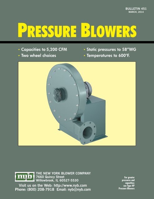
BULLETIN <strong>451</strong><br />
MARCH, 2014<br />
PRESSURE BLOWERS<br />
• Capacities to 5,200 CFM<br />
• Two wheel choices<br />
• Static pressures to 58”WG<br />
• Temperatures to 600°F.<br />
THE NEW YORK BLOWER COMPANY<br />
7660 Quincy Street<br />
Willowbrook, IL 60527-5530<br />
Visit us on the Web: http://www.nyb.com<br />
Phone: (800) 208-7918 Email: nyb@nyb.com<br />
For greater<br />
pressures and<br />
capacities:<br />
see Type HP<br />
<strong>Pressure</strong> <strong><strong>Blower</strong>s</strong>
ARRANGEMENT<br />
<strong>Pressure</strong> <strong>Blower</strong><br />
with motor.<br />
ARRANGEMENT<br />
<strong>Pressure</strong> <strong>Blower</strong> with<br />
plain pipe inlet.<br />
DESIGN FEATURES<br />
• <strong>Pressure</strong>s to 58”WG.<br />
•<br />
•<br />
Capacities to 5,200 CFM.<br />
Stable performance . . . the pressure curve<br />
remains stable from wide-open to closed-off . . .<br />
fan instability, or pulsation, is eliminated even<br />
when “turn-down” approaches zero flow.<br />
•<br />
Choice of wheel designs . . . standard aluminum<br />
wheel for optimum efficiency or optional steel<br />
wheel for more rugged applications.<br />
•<br />
PRESSURE BLOWERS<br />
...for process systems<br />
Efficiency . . . advanced wheel and aerodynamic<br />
housing design combine for air-handling efficiency<br />
superior to conventional radial-wheel designs.<br />
• Variable wheel diameters and a choice of six<br />
outlet sizes enable efficient fan selection across<br />
a wide range of volumes and pressures.<br />
• Choice of arrangements ... direct-drive and belt-drive.<br />
•<br />
Wide application range . . . designed for continuous<br />
operation in combustion, cooling, conveying, drying,<br />
and various process systems.<br />
ARRANGEMENT<br />
<strong>Pressure</strong> <strong>Blower</strong><br />
with motor.<br />
The <strong>New</strong> <strong>York</strong> <strong>Blower</strong> Company certifies<br />
that the <strong>Pressure</strong> <strong><strong>Blower</strong>s</strong> shown herein<br />
are licensed to bear the AMCA Seal.<br />
The ratings shown are based on tests<br />
and procedures performed in accordance<br />
with AMCA Publication 211 and<br />
comply with the requirements of the<br />
AMCA Certified Ratings Program.<br />
CONSTRUCTION FEATURES<br />
•<br />
All-welded steel housings . . . heavy-gauge<br />
housings are designed specifically to prevent<br />
“flexing” at high pressures.<br />
•<br />
•<br />
Flanges . . . continuously welded flanges match<br />
ANSI Class 125/150 hole pattern.<br />
Balance . . . all wheels are precision-balanced<br />
prior to assembly . . . fans with motors and drives<br />
mounted by nyb are given a final trim balance<br />
check at the specified running speed.<br />
•<br />
•<br />
Shafting . . . straightened to close tolerance to<br />
min imize “run-out” and ensure smooth operation.<br />
Inlet configuration . . . a choice of three inlet<br />
types allows units to be tailored to specific<br />
application requirements.<br />
•<br />
Lifting eyes . . . standard on all units for ease<br />
of handling and installation.<br />
• Finish . . . medium-green industrial coating.<br />
© Copyright 2010 by The <strong>New</strong> <strong>York</strong> <strong>Blower</strong> Company.<br />
® Registered trademark of The <strong>New</strong> <strong>York</strong> <strong>Blower</strong> Company.<br />
PAGE 2
• COMPANION FLANGES<br />
Designed to fit flush with fan inlet and outlet flanges,<br />
provided with a matching hole pattern.<br />
• DRAINS<br />
Tank flange is welded to the lowest point of the housing<br />
scroll . . . female pipe thread.<br />
•<br />
INLET FILTER<br />
Filters are available with a choice of three element<br />
types: wire mesh, hi-flow polyester, and ultra-synthetic.<br />
High-efficiency filter is flange-mounted. Furnished<br />
standard with outboard support bracket and available<br />
with or without protective hood.<br />
• SILENCERS<br />
Available to match standard inlet or outlet flange sizes.<br />
Heavy-welded construction filled with high-density,<br />
acoustical absorption material.<br />
•<br />
OUTLET DAMPERS<br />
Available as either an integral<br />
outlet design for fixed<br />
damper control or as a<br />
separate wafer design for<br />
variable-flow applications<br />
[shown]. Wafer damper is<br />
available with an optional<br />
actuator and positioner.<br />
•<br />
SHAFT SEALS<br />
Ceramic-felt shaft seals consist of compressed ceramic<br />
felt elements. Lubricated lip seals [Buna, Teflon®, and<br />
Viton®] and gas-purgeable, segmental bushing seals are<br />
also available. See your nyb representative for availability.<br />
[Teflon and Viton are registered trademarks of DuPont and DuPont Dow Elastomers, respectively.]<br />
•<br />
ACCESS DOOR<br />
Gasketed, flush-bolted door opens to provide access to<br />
the wheel.<br />
•<br />
HEAT-FAN CONSTRUCTION<br />
Available on Arrangements 1, 8, 9, and 10 steel<br />
wheel <strong>Pressure</strong> <strong><strong>Blower</strong>s</strong> up to 600°F. Modifications<br />
include shaft cooler and shaft-cooler guard.<br />
•<br />
LL-1 LOW LEAKAGE CONSTRUCTION<br />
Special construction to minimize leakage includes liptype<br />
shaft seal, non-rotatable housing with solid drive<br />
side, double studs, and neoprene gasketing. Maximum<br />
temperature 200°F. due to gasketing limitations. Not<br />
available with heat-fan construction. Contact your nyb<br />
representative for other options.<br />
•<br />
SPECIAL ALLOY CONSTRUCTION<br />
Airstream components can be constructed of a wide<br />
range of alternate alloys for corrosive applications.<br />
•<br />
ACCESSORIES/MODIFICATIONS<br />
UNITARY BASE<br />
Fan, motor, and guards can be mounted and shipped<br />
on a rugged, structural-steel base. Factory-assembled<br />
and run-tested prior to shipment.<br />
ARRANGEMENT<br />
<strong>Pressure</strong> <strong>Blower</strong><br />
with Venturi<br />
inlet, shaft and<br />
bearing guard,<br />
coupling<br />
guard, and<br />
motor.<br />
ARRANGEMENT<br />
<strong>Pressure</strong> <strong>Blower</strong><br />
with flanged<br />
inlet, flush-bolted<br />
cleanout door,<br />
motor, belt guard,<br />
and shaft and<br />
bearing guard.<br />
ARRANGEMENT<br />
<strong>Pressure</strong> <strong>Blower</strong><br />
with flanged<br />
inlet and<br />
optional weather<br />
cover/belt guard.<br />
PAGE 3
CHART II<br />
STEEL WHEEL<br />
HORSEPOWER CORRECTIONS<br />
18” <strong>Pressure</strong> <strong>Blower</strong> with 04 outlet<br />
to handle 400 CFM at 23 1 ⁄2”SP at<br />
.075 lbs./ft. 3 density. Aluminum<br />
wheels require 2.6 BHP as shown<br />
on page 7. Steel or stainless-steel<br />
wheels require [1.15 x 2.6] 3.0 BHP.<br />
WHEELS<br />
STANDARD ALUMINUM<br />
The unique Aluminum <strong>Pressure</strong> <strong>Blower</strong><br />
wheel is designed to provide efficient<br />
performance and reduced sound levels . . .<br />
the dual-taper design concept on all but<br />
the narrowest wheel sizes yields typical<br />
efficiencies up to 10 percentage points<br />
greater than conventional straight radial<br />
wheels. Riveted high-strength aluminum<br />
alloy blades and side plates minimize<br />
overhung wheel weight and starting<br />
inertia. Ductile-iron, taper-lock hubs<br />
make wheels easily removable.<br />
Note: Maximum operating temperature of<br />
aluminum wheel is 200°F.<br />
OPTIONAL STEEL<br />
Either welded steel or stainless-steel wheel<br />
construction is available in straight radial<br />
design. AMCA Certified Ratings Seal applies<br />
to <strong>Pressure</strong> <strong><strong>Blower</strong>s</strong> with aluminum-wheel<br />
design only. Air volume and pressure<br />
capabilities are the same as the dual-taper<br />
aluminum wheel, but brake horsepower<br />
requirements are typically higher. Refer to<br />
The <strong>New</strong> <strong>York</strong> <strong>Blower</strong> Company’s fanselection<br />
program for details.<br />
Note: Maximum operating temperature of steel<br />
wheel with heat fan construction is 600°F.<br />
Some fan-and-motor combinations with steel<br />
wheels may be restricted due to starting torque<br />
requirements. Consult nyb.<br />
Outlet<br />
size<br />
Wheel<br />
size<br />
BHP<br />
correction<br />
factors<br />
03<br />
14 to 22 0.96<br />
23 to 26 1.02<br />
04 14 to 26 1.15<br />
06<br />
14 to 18 1.06<br />
19 to 26 1.15<br />
08<br />
15 to 22 1.06<br />
23 to 26 1.15<br />
10 19 to 26 1.06<br />
12 19 to 26 1.06<br />
SPARK-RESISTANT CONSTRUCTION [SRC]<br />
Intended to minimize the potential for any two or more fan components to<br />
generate sparks within the airstream by rubbing or striking during operation.<br />
The following types are available:<br />
AMCA A [AIRSTREAM] SRC<br />
To include all airstream parts constructed of a spark-resistant alloy . . .<br />
maximum temperature: 200°F.<br />
AMCA B [WHEEL] SRC<br />
To include the fan wheel constructed of a spark-resistant alloy and a buffer plate<br />
around the housing shaft-hole opening . . . maximum temperature: 200°F.<br />
Wheel<br />
diameter<br />
CHART I<br />
MAXIMUM<br />
SAFE<br />
SPEEDS [RPM]†<br />
Aluminum<br />
wheel<br />
All Arr.<br />
Arr. 1, 4,<br />
4-V, 8, 9<br />
Steel<br />
wheel<br />
Arr. 10<br />
14 4000 4000 4000<br />
15 4000 4000 4000<br />
16 4000 4000 4000<br />
17 4000 4000 4000<br />
18 4000 4000 4000<br />
19 3900 3900 2992<br />
20 3900 3900 2918<br />
21 3900 3900 2851<br />
22 3900 3900 2787<br />
23 3800 3800 3178<br />
24 3800 3800 3121<br />
25 3800 3800 3068<br />
26 3800 3800 3017<br />
† derate for temperature not required.<br />
* Arr. 9 fans may have additional speed limits based on<br />
pedestal length.<br />
SAFETY EQUIPMENT<br />
Safety accessories are available<br />
from nyb, but selection of the<br />
appropriate devices is the<br />
responsibility of the systemdesigner<br />
who is familiar with<br />
the particular installation, or<br />
application, and can provide for<br />
guards for all exposed moving<br />
parts as well as protection<br />
from access to high-velocity<br />
airstreams. Neither nyb nor its<br />
sales representatives is in a<br />
position to make such a determination.<br />
Users and/or installers<br />
should read “Recommended<br />
Safety Practices for Air Moving<br />
Devices” as published by the<br />
Air Movement and Control<br />
Association International,<br />
Arlington Heights, Illinois.<br />
PAGE 4
PERFORMANCE<br />
USING PERFORMANCE CURVES<br />
Performance is shown according to outlet sizes for quick<br />
reference to duct diameter. Brake horsepower increments are<br />
identified on each curve. Recommended standard blower size<br />
and motor combinations, which are based on the most<br />
efficient area of operation, are listed on page 14 for<br />
Arrangements 4, 4-V, and 8. Nonstandard combinations are<br />
generally available, but are usually less efficient than the standard<br />
combinations.<br />
7-digit model<br />
number designates<br />
the wheel diameter,<br />
outlet size, wheel<br />
type, and nominal<br />
motor horsepower.<br />
Note: the last two<br />
digits showing<br />
motor horsepower<br />
are not required for<br />
Arrangement 1<br />
<strong>Pressure</strong> <strong><strong>Blower</strong>s</strong>.<br />
SIZING NOMENCLATURE<br />
21<br />
Wheel<br />
diameter<br />
EXAMPLE<br />
06<br />
Outlet<br />
size<br />
[inches]<br />
A<br />
7 1 ⁄2<br />
Wheel type<br />
A = aluminum<br />
S = steel/<br />
stainless steel<br />
PROCEDURE<br />
Determine the appropriate outlet size.<br />
Plot the CFM and SP [standard] and select a performance<br />
curve for the fan size that meets or slightly<br />
exceeds the required performance.<br />
Determine the BHP required for the point of operation . . .<br />
see page 4 for steel or stainless-steel wheel factors.<br />
Read to the right to select motor horsepower.<br />
STEPS<br />
EXAMPLE<br />
The 06 outlet is selected for 800 CFM at 32”SP.<br />
A Size 2106A will provide 800 CFM at 33.6”SP.<br />
2106A requires 6.3 BHP.<br />
2106S requires 7.2 BHP [6.3 x 1.15].<br />
A 7 1 ⁄2 HP motor will cover both wheel types.<br />
Note: The horsepower coverage of a given motor will increase 15% when a 1.15 service factor motor is utilized.<br />
CORRECTION FACTORS<br />
Performance is based on actual cubic feet per minute<br />
[ACFM] at the blower inlet at standard density [.075 lbs./ft. 3 ]<br />
and static pressure at the blower outlet. Static pressure<br />
capabilities are shown in inches water gauge [”WG].<br />
Air density corrections are necessary for proper selection<br />
when air density varies from the standard .075 lbs./ft. 3 at<br />
70˚F. at sea level. This also occurs when negative static<br />
pressure exists [rarefication] on the inlet side of the fan.<br />
Multiply the required static pressure at conditions by the<br />
appropriate factors in Charts III, IV, and V to obtain corrected<br />
pressure for blower selection. <strong>Pressure</strong> and BHP will be<br />
reduced at conditions by the inverse of these factors.<br />
Multiply one factor by the other if temperature, altitude, and<br />
rarefication are non-standard. For example: If the installation<br />
is located at an altitude of 4000 feet, the gas temperature<br />
is 300°F., and the inlet pressure is –40”WG, the correction<br />
factor is 1.84 [1.16 x 1.43 x 1.11].<br />
CHART III<br />
ALTITUDE [ft.]<br />
CORRECTIONS<br />
Alt. Factor<br />
0 1.00<br />
500 1.02<br />
1000 1.04<br />
1500 1.06<br />
2000 1.08<br />
2500 1.10<br />
3000 1.12<br />
3500 1.14<br />
4000 1.16<br />
4500 1.18<br />
5000 1.20<br />
6000 1.25<br />
7000 1.30<br />
8000 1.35<br />
9000 1.40<br />
10000 1.45<br />
CHART IV<br />
TEMPERATURE<br />
CORRECTIONS<br />
Temp.˚F. Factor<br />
0 .87<br />
20 .91<br />
40 .94<br />
60 .98<br />
70 1.00<br />
80 1.02<br />
100 1.06<br />
120 1.09<br />
140 1.13<br />
160 1.17<br />
180 1.21<br />
200 1.25<br />
300 1.43<br />
400 1.62<br />
500 1.81<br />
600 2.00<br />
CHART V<br />
RAREFICATION<br />
CORRECTIONS<br />
Neg. inlet<br />
pressure Factor<br />
“WG<br />
15 1.04<br />
20 1.05<br />
25 1.07<br />
30 1.08<br />
35 1.09<br />
40 1.11<br />
45 1.12<br />
50 1.14<br />
55 1.16<br />
60 1.17<br />
65 1.19<br />
70 1.21<br />
75 1.23<br />
85 1.26<br />
Nominal<br />
horsepower<br />
1403A-<br />
1803A<br />
STATIC PRESSURE [INCHES W.G.]<br />
25<br />
20<br />
15<br />
10<br />
5<br />
1803A<br />
1703A<br />
1603A<br />
1.0<br />
1503A<br />
1.0<br />
1.0 1.25<br />
1403A<br />
1.0<br />
1.5<br />
1.5<br />
1.5<br />
1.25<br />
1.5<br />
2.0<br />
0 50 100 150 200 250 300 350 400 450 500<br />
CFM<br />
2.0<br />
1.5<br />
2.0<br />
2.5<br />
1.75<br />
1.75<br />
2.5<br />
2.0<br />
3.0<br />
PAGE 5
PERFORMANCE AT 3500 RPM<br />
Aluminum Wheel<br />
<strong>Pressure</strong> <strong>Blower</strong><br />
NOTE: Values shown on curves indicate brake horsepower [BHP] required.<br />
1903A-<br />
2203A<br />
STATIC PRESSURE [INCHES W.G.]<br />
35<br />
30<br />
25<br />
20<br />
15<br />
2203A<br />
2103A<br />
2003A<br />
1903A<br />
3.0<br />
2.5<br />
3.0<br />
2.0 2.5<br />
3.0<br />
3.5<br />
4.0<br />
3.0<br />
3.5<br />
0 50 100 150 200 250 300 350 400 450 500 550 600<br />
CFM<br />
4.0<br />
4.0<br />
3.5<br />
5.0<br />
4.5<br />
4.0<br />
5.0<br />
6.0<br />
5.0<br />
2303A-<br />
2603A<br />
STATIC PRESSURE [INCHES W.G.]<br />
50<br />
45<br />
40<br />
35<br />
30<br />
2603A<br />
2503A<br />
2403A<br />
2303A<br />
4.0<br />
6.0<br />
5.0<br />
7.0<br />
7.5<br />
7.0<br />
6.0<br />
5.0<br />
8.0<br />
7.5<br />
7.0<br />
6.0<br />
8.0<br />
7.5<br />
9.0<br />
8.0<br />
9.0<br />
7.0<br />
7.5<br />
10.0<br />
9.0<br />
10.0<br />
25<br />
0 50 100 150 200 250 300 350 400 450 500 550 600 650 700<br />
CFM<br />
8.0<br />
STATIC PRESSURE [INCHES W.G.]<br />
25<br />
20<br />
1404A-<br />
1804A 1.0<br />
15<br />
10<br />
1.0<br />
1.0<br />
1.0<br />
1.5<br />
1.25<br />
1.5 2.0<br />
1.0 1.25 1.5<br />
1.25<br />
1.5 1.75<br />
2.0 2.5<br />
1.5<br />
1.75<br />
0 50 100 150 200 250 300 350 400 450 500 550 600 650<br />
CFM<br />
2.0<br />
1.75<br />
2.0<br />
2.5<br />
2.25<br />
2.25<br />
2.0<br />
3.0<br />
2.5<br />
3.0<br />
1804A<br />
1704A<br />
1604A<br />
1504A<br />
1404A<br />
Performance certified is installation Type B: Free inlet, Ducted outlet. Power rating (BHP) does not include transmission losses.<br />
Performance ratings do not include the effects of appurtenances (accessories).<br />
PAGE 6<br />
2
PERFORMANCE AT 3500 RPM<br />
Aluminum Wheel<br />
<strong>Pressure</strong> <strong>Blower</strong><br />
NOTE: Values shown on curves indicate brake horsepower [BHP] required.<br />
1904A-<br />
2204A<br />
STATIC PRESSURE [INCHES W.G.]<br />
4.0 4.5 5.0<br />
3.5<br />
35<br />
3.0<br />
2.5<br />
2204A<br />
3.0<br />
3.5<br />
2.5<br />
4.0<br />
4.5<br />
30<br />
2.0<br />
5.0<br />
3.0<br />
2.5<br />
3.5<br />
4.0<br />
2.0<br />
4.5<br />
2104A<br />
2.0<br />
2.5<br />
3.0<br />
3.5<br />
2004A<br />
4.0<br />
1904A<br />
25<br />
0 50 100 150 200 250 300 350 400 450 500 550 600 650 700 750 800<br />
CFM<br />
55<br />
2304A-<br />
2604A<br />
STATIC PRESSURE [INCHES W.G.]<br />
50<br />
45<br />
40<br />
35<br />
14.0<br />
12.0<br />
10.0 11.0<br />
9.0 10.0<br />
13.0<br />
12.0<br />
15.0<br />
11.0<br />
14.0<br />
13.0<br />
16.0<br />
15.0<br />
12.0<br />
14.0<br />
17.0<br />
2604A<br />
2504A<br />
2404A<br />
2304A<br />
30<br />
0 100 200 300 400 500 600 700 800 900 1000<br />
CFM<br />
30<br />
1406A-<br />
1806A<br />
STATIC PRESSURE [INCHES W.G.]<br />
3.5 4.0 4.5 5.0 5.5<br />
3.0<br />
6.0 6.5<br />
2.5<br />
7.0<br />
25<br />
2.0<br />
2.5 3.0 3.5 4.0 4.5<br />
1806A<br />
2.0<br />
5.0<br />
1.5<br />
5.5<br />
6.0<br />
20 1706A<br />
2.0<br />
2.5<br />
3.0<br />
3.5<br />
4.0<br />
1606A 1.5<br />
4.5<br />
1.5<br />
2.0<br />
2.5<br />
5.0<br />
3.0<br />
1506A<br />
3.5<br />
5.5<br />
4.0<br />
15<br />
1.0<br />
1.5<br />
1406A<br />
2.0<br />
4.5<br />
2.5<br />
5.0<br />
3.0<br />
3.5<br />
10<br />
0 100 200 300 400 500 600 700 800 900 1000 1100 1200 1300<br />
CFM<br />
Performance certified is installation Type B: Free inlet, Ducted outlet. Power rating (BHP) does not include transmission losses.<br />
Performance ratings do not include the effects of appurtenances (accessories).<br />
PAGE 7
PERFORMANCE AT 3500 RPM<br />
Aluminum Wheel<br />
<strong>Pressure</strong> <strong>Blower</strong><br />
NOTE: Values shown on curves indicate brake horsepower [BHP] required.<br />
1906A-<br />
2206A<br />
STATIC PRESSURE [INCHES W.G.]<br />
40<br />
4.0<br />
5.0<br />
6.0<br />
7.0<br />
7.5<br />
3.0<br />
8.0<br />
4.0<br />
5.0<br />
35<br />
2.0<br />
6.0<br />
3.0<br />
9.0<br />
7.0<br />
2206A 2.0<br />
7.5<br />
8.0<br />
10.0<br />
2106A<br />
4.0<br />
3.0<br />
5.0<br />
30<br />
2006A 2.0<br />
6.0<br />
3.0<br />
4.0<br />
1906A<br />
2.0<br />
5.0<br />
7.0<br />
7.5<br />
25<br />
6.0<br />
8.0<br />
7.0<br />
20<br />
7.5<br />
0 100 200 300 400 500 600 700 800 900 1000 1100 1200 1300<br />
CFM<br />
2306A-<br />
2606A<br />
STATIC PRESSURE [INCHES W.G.]<br />
55<br />
50<br />
45<br />
40<br />
2606A<br />
2506A<br />
2406A<br />
2306A<br />
4.0<br />
6.0<br />
10.0<br />
7.0 7.5 8.0 10.0<br />
7.0 7.5 8.0<br />
6.0<br />
7.0<br />
7.5 8.0<br />
6.0<br />
7.0<br />
7.5 8.0<br />
6.0<br />
5.0<br />
12.0<br />
14.0 15.0 16.0<br />
12.0 14.0 15.0<br />
10.0 12.0<br />
14.0<br />
10.0<br />
12.0<br />
35<br />
0 100 200 300 400 500 600 700 800 900 1000 1100 1200 1300<br />
CFM<br />
30<br />
1508A-<br />
STATIC PRESSURE [INCHES W.G.]<br />
25<br />
1708A<br />
20<br />
3.0<br />
2.0<br />
4.0<br />
1608A<br />
2208A<br />
2.0 3.0<br />
1508A<br />
15<br />
10<br />
1808A<br />
2.0<br />
2.0<br />
3.0<br />
4.0<br />
3.0 4.0<br />
5.0<br />
4.0<br />
6.0<br />
5.0<br />
5.0<br />
7.0<br />
6.0<br />
5.0<br />
7.5<br />
6.0<br />
8.0<br />
7.0<br />
6.0<br />
7.5<br />
7.0<br />
9.0<br />
8.0<br />
7.5<br />
10.0<br />
8.0<br />
9.0<br />
11.0<br />
7.0 7.5<br />
0 200 400 600 800 1000 1200 1400 1600 1800 2000 2200 2400<br />
CFM<br />
10.0<br />
Performance certified is installation Type B: Free inlet, Ducted outlet. Power rating (BHP) does not include transmission losses.<br />
Performance ratings do not include the effects of appurtenances (accessories).<br />
PAGE 8
PERFORMANCE AT 3500 RPM<br />
Aluminum Wheel<br />
<strong>Pressure</strong> <strong>Blower</strong><br />
NOTE: Values shown on curves indicate brake horsepower [BHP] required.<br />
1908A-<br />
2208A<br />
STATIC PRESSURE [INCHES W.G.]<br />
42<br />
37<br />
32<br />
27<br />
22<br />
2208A<br />
2108A<br />
2008A<br />
1908A<br />
4.0<br />
4.0<br />
4.0<br />
4.0<br />
6.0<br />
6.0<br />
7.5<br />
7.0<br />
6.0<br />
6.0<br />
8.0<br />
7.5 8.0<br />
7.0<br />
7.0<br />
7.5<br />
7.0<br />
8.0<br />
10.0<br />
7.5<br />
8.0<br />
10.0<br />
12.0<br />
0 200 400 600 800 1000 1200 1400 1600 1800 2000 2200 2400 2600<br />
CFM<br />
10.0<br />
12.0<br />
10.0<br />
14.0<br />
12.0<br />
15.0<br />
14.0<br />
16.0<br />
12.0<br />
15.0<br />
14.0<br />
16.0<br />
18.0<br />
15.0<br />
14.0<br />
15.00<br />
2308A-<br />
2608A<br />
STATIC PRESSURE [INCHES W.G.]<br />
57<br />
14.0 15.0 16.0 18.0<br />
12.0<br />
20.0<br />
10.0<br />
22.0<br />
12.0<br />
14.0 15.0<br />
52<br />
8.0<br />
16.0 24.0<br />
10.0<br />
18.0<br />
25.0<br />
6.0<br />
8.0<br />
20.0<br />
26.0<br />
6.0<br />
22.0<br />
47 2608A<br />
10.0<br />
12.0 14.0 15.0<br />
16.0<br />
8.0<br />
24.0<br />
18.0<br />
42<br />
2508A<br />
6.0<br />
10.0 12.0<br />
8.0<br />
20.0<br />
14.0<br />
2408A<br />
15.0<br />
6.0<br />
16.0<br />
22.0<br />
2308A<br />
4.0<br />
18.0<br />
37<br />
0 200 400 600 800 1000 1200 1400 1600 1800 2000 2200 2400<br />
CFM<br />
1910A-<br />
2210A<br />
STATIC PRESSURE [INCHES W.G.]<br />
42<br />
37<br />
32<br />
27<br />
22<br />
4.0<br />
2210A 4.0<br />
2110A<br />
2010A<br />
1910A<br />
4.0<br />
4.0<br />
6.0<br />
6.0<br />
6.0<br />
8.0<br />
6.0<br />
8.0<br />
10.0<br />
8.0<br />
10.0<br />
8.0<br />
12.0<br />
10.0<br />
12.0<br />
14.0<br />
10.0<br />
15.0<br />
14.0<br />
12.0<br />
16.0<br />
15.0<br />
12.0<br />
16.0<br />
14.0<br />
18.0<br />
15.0<br />
14.0<br />
18.0<br />
20.0<br />
16.0<br />
15.0<br />
20.0<br />
16.0<br />
22.0<br />
18.0<br />
24.0<br />
25.0<br />
0 300 600 900 1200 1500 1800 2100 2400 2700 3000 3300<br />
CFM<br />
22.0<br />
20.0<br />
26.0<br />
24.0<br />
Performance certified is installation Type B: Free inlet, Ducted outlet. Power rating (BHP) does not include transmission losses.<br />
Performance ratings do not include the effects of appurtenances (accessories).<br />
PAGE 9
PERFORMANCE AT 3500/3550 RPM<br />
Aluminum Wheel<br />
<strong>Pressure</strong> <strong>Blower</strong><br />
NOTE: Values shown on curves indicate brake horsepower [BHP] required.<br />
2310A-<br />
2610A<br />
STATIC PRESSURE [INCHES W.G.]<br />
60<br />
55<br />
50<br />
45<br />
40<br />
2610A<br />
2510A<br />
2410A<br />
10.0<br />
2310A<br />
10.0<br />
10.0<br />
10.0<br />
15.0<br />
15.0<br />
15.0<br />
15.0<br />
20.0<br />
20.0<br />
20.0<br />
20.0<br />
25.0 30.0<br />
0 300 600 900 1200 1500 1800 2100 2400 2700 3000 3300 3600<br />
CFM<br />
25.0<br />
25.0<br />
30.0<br />
25.0<br />
35.0<br />
30.0<br />
35.0<br />
30.0<br />
40.0<br />
35.0<br />
1912A-<br />
2212A<br />
[INCHES W.G.]<br />
STATIC PRESSURE<br />
45<br />
40<br />
35<br />
30<br />
2212A<br />
2112A<br />
2012A<br />
1912A<br />
10.0<br />
10.0<br />
15.0 20.0<br />
15.0 20.0<br />
10.0 15.0<br />
10.0<br />
15.0<br />
25.0<br />
20.0<br />
25.0<br />
30.0<br />
25.0<br />
30.0<br />
35.0<br />
40.0<br />
35.0<br />
25<br />
20.0<br />
20<br />
30.0<br />
25.0<br />
0 400 800 1200 1600 2000 2400 2800 3200 3600 4000 4400 4800 5200<br />
CFM<br />
2312A-<br />
2612A<br />
STATIC PRESSURE [INCHES W.G.]<br />
56<br />
51<br />
46<br />
41<br />
36<br />
2612A<br />
2512A<br />
2412A<br />
2312A<br />
10.0<br />
10.0<br />
10.0<br />
10.0<br />
15.0<br />
15.0<br />
15.0<br />
20.0<br />
15.0<br />
20.0<br />
25.0 30.0 35.0<br />
25.0 30.0<br />
20.0 25.0<br />
20.0<br />
25.0<br />
0 400 800 1200 1600 2000 2400 2800 3200 3600 4000 4400 4800 5200<br />
CFM<br />
30.0<br />
35.0<br />
30.0<br />
40.0<br />
35.0<br />
40.0<br />
45.0<br />
35.0<br />
40.0<br />
45.0<br />
50.0<br />
45.0<br />
40.0<br />
50.0<br />
55.0<br />
Performance certified is installation Type B: Free inlet, Ducted outlet. Power rating (BHP) does not include transmission losses.<br />
Performance ratings do not include the effects of appurtenances (accessories).<br />
PAGE 10
Size<br />
SPECIFICATIONS<br />
U.S. standard sheet gauge to 7 gauge. Dimensions in inches. Weights in pounds. WR 2 in lb.-ft. 2 .<br />
WHEEL SPECIFICATIONS<br />
Aluminum<br />
Steel<br />
Wt. WR 2 Wt. WR 2<br />
1403 10.1 0.96 19.7 2.74<br />
1404 8.5 1.43 18.0 3.04<br />
1406 11.7 2.40 20.5 3.46<br />
1503 10.8 1.23 21.8 3.59<br />
1504 8.8 1.69 19.0 3.68<br />
1506, 1508 11.8 2.40 21.5 4.16<br />
1603 11.5 1.53 23.9 4.56<br />
1604 9.0 1.98 20.0 4.41<br />
1606, 1608 12.1 2.50 23.0 5.07<br />
1703 12.3 1.93 26.3 5.79<br />
1704 9.3 2.30 21.0 5.22<br />
1706, 1708 12.2 2.60 24.5 6.09<br />
1803 13.0 2.36 28.6 7.16<br />
1804 9.5 2.65 22.0 6.13<br />
1806, 1808 12.4 2.60 26.0 7.25<br />
1903 14.2 2.92 31.1 8.42<br />
1904, 1906 12.0 3.73 29.5 9.16<br />
1908, 1910 15.1 5.10 34.5 10.72<br />
1912 12.9 5.07 32.8 10.15<br />
2003 15.1 5.02 33.7 10.23<br />
2004, 2006 12.3 4.22 31.0 10.67<br />
2008, 2010 15.3 5.20 36.5 12.56<br />
2012 13.1 5.21 36.1 12.37<br />
2103 16.0 4.24 36.5 12.31<br />
2104, 2106 12.5 4.74 32.5 12.33<br />
2108, 2110 15.5 5.30 38.0 14.42<br />
2112 13.3 5.34 39.4 14.91<br />
2203 17.1 5.02 39.3 14.70<br />
2204, 2206 12.8 5.31 34.0 14.16<br />
2208, 2210 15.6 5.40 40.0 16.66<br />
2212 13.5 5.48 42.9 17.80<br />
2303 18.3 6.07 49.4 20.83<br />
2304 19.8 6.50 52.5 22.27<br />
2306, 2308 18.5 8.42 45.0 20.93<br />
2310, 2312 21.7 10.60 53.5 24.35<br />
2403 19.4 7.16 53.1 24.50<br />
2404 20.9 7.80 56.4 26.14<br />
2406, 2408 18.8 9.29 48.0 23.79<br />
2410, 2412 21.9 10.80 56.0 27.75<br />
2503 20.5 8.33 56.9 28.64<br />
2504 22.0 9.00 60.4 30.49<br />
2506, 2508 19.0 10.22 50.0 26.89<br />
2510, 2512 21.9 11.00 58.5 31.46<br />
2603 21.8 9.63 60.9 33.27<br />
2604 23.1 10.30 64.5 35.36<br />
2606, 2608 19.3 11.20 52.0 30.24<br />
2610, 2612 22.3 11.20 61.0 35.48<br />
PAGE 11<br />
Wheel<br />
diameter<br />
Wheel<br />
diameter<br />
MATERIAL SPECIFICATIONS<br />
Sides<br />
Standard<br />
HOUSING<br />
Scroll<br />
SHAFT DIAMETER<br />
SHAFT DIAMETER<br />
Inlet<br />
plate<br />
Drive<br />
plate<br />
14-18 10 10 1 ⁄4 10<br />
19-22 10 10 1 ⁄4 10<br />
23-26 10 10 1 ⁄4 10<br />
Wheel<br />
diameter<br />
Arrangement 9 Arrangement 10<br />
Heat Fan with<br />
Shaft Seal Standard Heat Fan<br />
14-18 1 7 ⁄16 1 7 ⁄16 1 7 ⁄16 1 7 ⁄16<br />
19-22 1 11 ⁄16 1 11 ⁄16 1 7 ⁄16 1 7 ⁄16<br />
23-26 1 15 ⁄16 1 15 ⁄16 1 11 ⁄16 1 11 ⁄16<br />
Wheel<br />
diameter<br />
BEARINGS<br />
*<br />
Arrangement 1/9 Arrangement<br />
Inboard Outboard 8<br />
Arrangement<br />
10<br />
14-18 A A‡ A A<br />
19-22 B B A B<br />
23-26 C B‡ A B<br />
A–200 Series ball bearing. B–22400 Series roller bearing.<br />
C–300 Series ball bearing.<br />
*<br />
nyb reserves the right to substitute bearings of equal rating.<br />
‡ Fans with heat fan construction and shaft seal:<br />
Arr. 1: Sizes 23-26 include a shaft turndown at the outboard bearing, with a<br />
bearing size of 1 11 ⁄16”. Inboard bearing size is 1 15 ⁄16”.<br />
Arr. 9: Sizes 14-18 include a Type B outboard bearing, in lieu of the standard Type<br />
FLANGE<br />
Arrangement 1 Arrangement 8<br />
Standard<br />
Heat Fan with<br />
Shaft Seal<br />
DIMENSIONS [INCHES]<br />
Standard<br />
Size I.D. O.D. Bolt circle<br />
Heat Fan with<br />
Shaft Seal<br />
14-18 1 7 ⁄16 1 7 ⁄16 1 7 ⁄16 1 7 ⁄16<br />
19-22 1 7 ⁄16 1 11 ⁄16 1 7 ⁄16 1 7 ⁄16<br />
23-26 1 11 ⁄16 1 15 ⁄16‡ 1 7 ⁄16 1 11 ⁄16<br />
I.D. B.C. O.D.<br />
Holes†<br />
No. – size<br />
03 3 07 1 ⁄2 06 4 – 3 ⁄4”<br />
04 4 09 07 1 ⁄2 8 – 3 ⁄4”<br />
05 5 10 08 1 ⁄2 8 – 7 ⁄8”<br />
06 6 11 09 1 ⁄2 8 – 7 ⁄8”<br />
08 8 13 1 ⁄2 11 3 ⁄4 8 – 7 ⁄8”<br />
10 10 16 14 1 ⁄4 12 – 1”<br />
12 12 19 17 12 – 1”<br />
†Holes straddle centerline. ANSI Class 125/150 hole pattern. Flange thickness 3 ⁄8”
ARRANGEMENTS<br />
1/9<br />
PRESSURE<br />
BLOWERS<br />
Maximum Airstream<br />
Temperature:<br />
200°F. – aluminum wheel.<br />
300°F. – steel wheel.<br />
600°F. – heat fan.<br />
L<br />
JJ<br />
PLAIN PIPE<br />
INLET<br />
JJ<br />
VENTURI<br />
INLET<br />
M<br />
JJ<br />
H<br />
N<br />
K<br />
A<br />
R<br />
HOUSING<br />
CL<br />
S<br />
T U<br />
T U<br />
9/16 DIA. HOLES<br />
1 1/4"<br />
G<br />
D<br />
B<br />
C<br />
F<br />
ARRANGEMENT<br />
4<br />
PRESSURE<br />
BLOWERS<br />
Maximum Airstream<br />
Temperature:<br />
180°F.<br />
L<br />
JJ<br />
PLAIN PIPE<br />
INLET<br />
JJ<br />
VENTURI<br />
INLET<br />
M<br />
JJ<br />
H<br />
HOUSING<br />
CL<br />
ARR.8 PRESSURE BLOWER<br />
NN<br />
A<br />
R<br />
S<br />
T U<br />
T U<br />
9/16" DIA. HOLES<br />
G<br />
D<br />
B<br />
C<br />
F<br />
ARRANGEMENT<br />
4-V<br />
PRESSURE<br />
BLOWERS<br />
C<br />
F<br />
H FILE NAME: A1<br />
ARR.10 PRESSURE DATE 6-9-04 BLOWER<br />
TMM<br />
M<br />
JJ<br />
B<br />
Maximum Airstream<br />
Temperature:<br />
120°F.<br />
G<br />
D<br />
ARRANGEMENT<br />
8<br />
PRESSURE<br />
BLOWERS<br />
Maximum Airstream<br />
Temperature:<br />
200°F. – aluminum wheel.<br />
300°F. – steel wheel.<br />
600°F. – heat fan.<br />
L<br />
JJ<br />
PLAIN PIPE<br />
INLET<br />
JJ<br />
VENTURI<br />
INLET<br />
M<br />
JJ<br />
H<br />
NN<br />
K<br />
12 1/4<br />
FILE NAME: A4<br />
HOUSING<br />
DATE 11-9-04 CL<br />
TMM<br />
A<br />
R<br />
S<br />
9/16 DIA. HOLES<br />
T U<br />
T U<br />
1 1/4"<br />
G<br />
D<br />
B<br />
C<br />
F<br />
ARRANGEMENT<br />
10<br />
PRESSURE<br />
BLOWERS<br />
Maximum Airstream<br />
Temperature:<br />
200°F. – aluminum wheel.<br />
300°F. – steel wheel.<br />
600°F. – heat fan.<br />
L<br />
JJ<br />
PLAIN PIPE<br />
INLET<br />
JJ<br />
VENTURI<br />
INLET<br />
M<br />
JJ<br />
H<br />
N<br />
A<br />
K<br />
R<br />
HOUSING<br />
CL<br />
S<br />
V<br />
V<br />
SIZES 14-18: 9/16"<br />
SIZES 19-26: 3/4"<br />
T U<br />
T U<br />
G<br />
D<br />
B<br />
C<br />
F<br />
PAGE 12
ARRANGEMENTS 1, 4, 4-V, 8, 9, 10<br />
Dimensions not to be used for construction unless certified. Bare fan weight does not include wheel or motor. Weights in pounds. Wheel weights on page 11.<br />
HOUSING DIMENSIONS [INCHES]<br />
Fan Size Outlet Size Inlet Size B C D F G M<br />
JJ [Inlet types]<br />
Flanged Plain pipe Venturi<br />
L<br />
03 05<br />
2 7 ⁄8 5 1 ⁄16 4 11 ⁄16 4 9 ⁄16 5 9 ⁄16<br />
04 06<br />
14-18<br />
5 9 ⁄16 5 3 ⁄16 4 13 ⁄16 6 5 ⁄8<br />
18<br />
06 08<br />
⁄4 13 5 ⁄8 11 3 ⁄4 14 3 ⁄8 12 3 3 7 ⁄8<br />
⁄4<br />
6<br />
08 08<br />
⁄4 6 3 ⁄4 6 3 ⁄8 6 3 ⁄8 8 5 ⁄8<br />
03 05<br />
2 7 ⁄8 5 9 ⁄16 5 3 ⁄16 5 3 ⁄16 5 9 ⁄16<br />
19-22<br />
04 06<br />
17 6<br />
06 06<br />
⁄4<br />
3 7 ⁄8<br />
1 ⁄16 5 11 ⁄16 5 5 ⁄16 6 5 ⁄8<br />
16<br />
08 08<br />
⁄2 14 7 ⁄8 17 1 ⁄2 15 1 ⁄2<br />
6 3 ⁄4 6 3 ⁄8 6 3 ⁄8 8 5 ⁄8<br />
21 3 6 1 ⁄4<br />
10 10 ⁄4<br />
12 12 23<br />
14 1 ⁄2<br />
7 1 ⁄4 7 1 ⁄4 6 7 ⁄8 6 7 ⁄8 10 3 ⁄4<br />
03 05<br />
3 5 ⁄8 6 5 ⁄16 5 15 ⁄16 5 9 ⁄16 5 9 ⁄16<br />
23-26<br />
04 06<br />
19<br />
6 5<br />
06 08<br />
7 6 5 ⁄8 6 5 ⁄8<br />
⁄8<br />
19<br />
08 08<br />
⁄2 17 5 ⁄8 20 5 ⁄8 18 1 5<br />
⁄4<br />
8 5 ⁄8<br />
10 10<br />
12 12<br />
23<br />
7 1 ⁄4 7 1 ⁄4 6 7 ⁄8 6 7 ⁄8 10 3 ⁄4<br />
BARE FAN WEIGHTS AND MOTOR LIMITATIONS<br />
Tolerance:± 1 ⁄8”<br />
Inlet<br />
Outlet<br />
Arr. 9<br />
Fan<br />
Size<br />
Pedestal<br />
Size Size<br />
Number<br />
Weight Weight Max. Motor Size<br />
Fan<br />
Size Outlet<br />
Size<br />
14-18<br />
15-18<br />
19-22<br />
23-26<br />
03<br />
04<br />
06<br />
08<br />
03<br />
04<br />
06<br />
08<br />
10<br />
12<br />
03<br />
04<br />
06<br />
08<br />
10<br />
12<br />
05<br />
06<br />
08<br />
08<br />
05<br />
06<br />
06<br />
08<br />
10<br />
12<br />
05<br />
06<br />
08<br />
08<br />
10<br />
12<br />
Arr. 1<br />
Wt.<br />
200<br />
205<br />
220<br />
220<br />
270<br />
275<br />
275<br />
290<br />
300<br />
320<br />
330<br />
350<br />
365<br />
365<br />
385<br />
395<br />
Motor Frame<br />
Size (Arr. 4, 8)<br />
143T-145T<br />
182T-184T<br />
143T-145T<br />
182T-184T<br />
143T-145T<br />
182T-184T<br />
213T-215T<br />
182T-184T<br />
213T-215T<br />
143T-145T<br />
182T-184T<br />
213T-215T<br />
143T-145T<br />
182T-184T<br />
213T-215T<br />
143T-145T<br />
182T-184T<br />
213T-215T<br />
182T-184T<br />
213T-215T<br />
254T-256T<br />
213T-215T<br />
254T-256T<br />
284TS-286TS<br />
254T-256T<br />
284T-286T<br />
324TS-326TS<br />
182T-184T<br />
213T-215T<br />
254T-256T<br />
182T-184T<br />
213T-215T<br />
254T-256T<br />
182T-184T<br />
213T-215T<br />
254T-256T<br />
213T-215T<br />
254T-256T<br />
284TS-286TS<br />
254T-256T<br />
284TS-286TS<br />
324TS-326TS<br />
284TS-286TS<br />
324TS-326TS<br />
N/A: Not Available due to motor shaft/wheel fit.<br />
Weight<br />
Arr.<br />
4<br />
145<br />
170<br />
150<br />
175<br />
165<br />
190<br />
190<br />
235<br />
245<br />
245<br />
260<br />
290<br />
270<br />
300<br />
320<br />
345<br />
270<br />
300<br />
275<br />
300<br />
285<br />
315<br />
290<br />
320<br />
335<br />
360<br />
345<br />
370<br />
Arr.<br />
8<br />
285<br />
295<br />
300<br />
305<br />
310<br />
315<br />
370<br />
375<br />
380<br />
385<br />
390<br />
385<br />
390<br />
395<br />
410<br />
415<br />
430<br />
415<br />
430<br />
445<br />
455<br />
460<br />
435<br />
445<br />
460<br />
465<br />
470<br />
490<br />
460<br />
465<br />
485<br />
475<br />
495<br />
495<br />
500<br />
505<br />
515<br />
520<br />
Arr. 4-V<br />
Motor Frame<br />
Size Weight<br />
182TC-184TC<br />
182TC-184TC<br />
182TC-184TC<br />
213TC-215TC<br />
182TC-184TC<br />
213TC-215TC<br />
182TC-184TC<br />
213TC-215TC<br />
182TC-184TC<br />
213TC-215TC<br />
182TC-184TC<br />
213TC-215TC<br />
182TC-184TC<br />
213TC-215TC<br />
254TC-256TC<br />
213TC-215TC<br />
254TC-256TC<br />
284TSC-286TSC<br />
254TC-256TC<br />
284TSC-286TSC<br />
324TSC-326TSC<br />
182TC-184TC<br />
213TC-215TC<br />
254TC-256TC<br />
182TC-184TC<br />
213TC-215TC<br />
254TC-256TC<br />
182TC-184TC<br />
213TC-215TC<br />
254TC-256TC<br />
213TC-215TC<br />
254TC-256TC<br />
284TSC-286TSC<br />
254TC-256TC<br />
284TSC-286TSC<br />
324TSC-326TSC<br />
284TSC-286TSC<br />
324TSC-326TSC<br />
PAGE 13<br />
120<br />
130<br />
135<br />
145<br />
160<br />
170<br />
175<br />
190<br />
190<br />
215<br />
205<br />
230<br />
230<br />
235<br />
255<br />
265<br />
14-18<br />
19-22<br />
03<br />
04<br />
06,08<br />
03<br />
04,06<br />
08,10<br />
12<br />
03,04<br />
23-26 06,08<br />
10,12<br />
1 190<br />
2 225<br />
3 260<br />
4 300<br />
1 195<br />
2 235<br />
3 265<br />
4 305<br />
1 210<br />
2 250<br />
3 280<br />
4 325<br />
5 280<br />
6 300<br />
7 340<br />
8 360<br />
9 370<br />
5 295<br />
6 315<br />
7 355<br />
8 375<br />
9 385<br />
5 315<br />
6 335<br />
7 375<br />
8 395<br />
9 405<br />
5 340<br />
6 360<br />
7 405<br />
8 420<br />
9 430<br />
10 435<br />
11 455<br />
12 465<br />
13 550<br />
10 440<br />
11 460<br />
12 470<br />
13 555<br />
10 460<br />
11 480<br />
12 490<br />
13 570<br />
220<br />
230<br />
245<br />
290<br />
305<br />
325<br />
350<br />
355<br />
360<br />
375<br />
Arr. 10<br />
ODP TEFC C-NW<br />
215T 215T 165 ⁄8<br />
256T<br />
256T<br />
254T<br />
254T<br />
185⁄8<br />
185⁄8<br />
Tolerance:± 1 ⁄8”
ARRANGEMENTS 4, 4-V, 8<br />
Dimensions not to be used for construction unless certified. Note: See page 12 for dimensional drawings.<br />
Wheel<br />
dia.<br />
14-18<br />
15-18<br />
19-22<br />
23-26<br />
Outlet<br />
Size<br />
03<br />
04<br />
06<br />
08<br />
03<br />
04<br />
06<br />
08<br />
10<br />
12<br />
03<br />
04<br />
06<br />
08<br />
10<br />
12<br />
Inlet<br />
flange<br />
05<br />
06<br />
08<br />
08<br />
05<br />
06<br />
06<br />
08<br />
10<br />
12<br />
05<br />
06<br />
08<br />
08<br />
10<br />
12<br />
N/A = Not Available<br />
Arr. 4 & 8 Motor<br />
Frame Size<br />
143T-145T<br />
182T-184T<br />
143T-145T<br />
182T-184T<br />
143T-145T<br />
182T-184T<br />
213T-215T<br />
182T-184T<br />
213T-215T<br />
143T-145T<br />
182T-184T<br />
213T-215T<br />
143T-145T<br />
182T-184T<br />
213T-215T<br />
143T-145T<br />
182T-184T<br />
213T-215T<br />
182T-184T<br />
213T-215T<br />
254T-256T<br />
213T-215T<br />
254T-256T<br />
284TS-286TS<br />
254T-256T<br />
284TS-286TS<br />
324TS-326TS<br />
182T-184T<br />
213T-215T<br />
254T-256T<br />
182T-184T<br />
213T-215T<br />
254T-256T<br />
182T-184T<br />
213T-215T<br />
254T-256T<br />
213T-215T<br />
254T-256T<br />
284TS-286TS<br />
254T-256T<br />
284TS-286TS<br />
324TS-326TS<br />
284TS-286TS<br />
324TS-326TS<br />
A<br />
Arr.<br />
4<br />
17 3 ⁄4<br />
19<br />
17 3 ⁄4<br />
19<br />
17 3 ⁄4<br />
19<br />
19 3 ⁄4<br />
19<br />
19 3 ⁄4<br />
23<br />
24<br />
24 3 ⁄4<br />
23<br />
24<br />
24 3 ⁄4<br />
23<br />
24<br />
24 3 ⁄4<br />
24<br />
24 3 ⁄4<br />
26<br />
24 3 ⁄4<br />
26<br />
26 3 ⁄4<br />
26<br />
26 3 ⁄4<br />
29 1 ⁄4<br />
24<br />
24 3 ⁄4<br />
26<br />
24<br />
24 3 ⁄4<br />
26<br />
24<br />
24 3 ⁄4<br />
26<br />
24 3 ⁄4<br />
26<br />
26 3 ⁄4<br />
26<br />
26 3 ⁄4<br />
29 1 ⁄4<br />
28 1 ⁄4<br />
29 1 ⁄4<br />
Arr.<br />
8†<br />
19 1 ⁄2<br />
19 1 ⁄2<br />
23 5 ⁄8<br />
26 5 ⁄8<br />
H*<br />
Arr. Arr.<br />
4 8<br />
18<br />
23 1 ⁄2<br />
19<br />
24 1 ⁄2<br />
21 3 ⁄8<br />
26 7 ⁄8<br />
26 7 ⁄8<br />
24<br />
25<br />
25<br />
26 7 ⁄8<br />
32 1 ⁄4<br />
26 7 ⁄8<br />
32 1 ⁄4<br />
331⁄4<br />
37 1 ⁄4<br />
25 1 ⁄8<br />
30 1 ⁄2<br />
26 1 ⁄2<br />
31 7 ⁄8<br />
26 1 ⁄2<br />
31 7 ⁄8<br />
26 1 ⁄2<br />
31 7 ⁄8<br />
33 1 ⁄4<br />
37 1 ⁄4<br />
37 1 ⁄4<br />
38<br />
40 5 ⁄8<br />
39<br />
41 5 ⁄8<br />
41 3 ⁄8<br />
44<br />
46 5 ⁄8<br />
44<br />
46 5 ⁄8<br />
38 1 ⁄2<br />
41 1 ⁄8<br />
43 3 ⁄4<br />
39 1 ⁄2<br />
42 1 ⁄8<br />
44 3 ⁄4<br />
39 1 ⁄2<br />
42 1 ⁄8<br />
44 3 ⁄4<br />
44<br />
46 5 ⁄8<br />
51 3 ⁄8<br />
46 5 ⁄8<br />
51 3 ⁄8<br />
53 3 ⁄8<br />
52 3 ⁄8<br />
54 3 ⁄8<br />
57 7 ⁄8<br />
42 3 ⁄4<br />
45 3 ⁄8<br />
50 1 ⁄8<br />
44 1 ⁄8<br />
46 3 ⁄4<br />
51 1 ⁄2<br />
44 1 ⁄8<br />
46 3 ⁄4<br />
51 1 ⁄2<br />
46 3 ⁄4<br />
51 1 ⁄2<br />
53 1 ⁄2<br />
52 7 ⁄8<br />
54 7 ⁄8<br />
58 5 ⁄8<br />
54 7 ⁄8<br />
58 5 ⁄8<br />
Arr. 4-V<br />
Motor Frame<br />
Size<br />
182TC-184TC<br />
182TC-184TC<br />
182TC-184TC<br />
213TC-215TC<br />
182TC-184TC<br />
213TC-215TC<br />
182TC-184TC<br />
213TC-215TC<br />
182TC-184TC<br />
213TC-215TC<br />
182TC-184TC<br />
213TC-215TC<br />
182TC-184TC<br />
213TC-215TC<br />
254TC-256Tc<br />
213TC-215TC<br />
254TC-256TC<br />
284TCS-286TCS<br />
254TS-256TS<br />
284TSC-286TSC<br />
324TSC-326TSC<br />
182TC-184TC<br />
213TC-215TC<br />
254TC-256TC<br />
182TC-184TC<br />
213TC-215TC<br />
254TC-256TC<br />
182TC-184TC<br />
213TC-215TC<br />
254TC-256TC<br />
213TC-215TC<br />
254TC-256TC<br />
284TS-286TS<br />
254TC-256TC<br />
284TCS-286TCS<br />
324TCS-326TCS<br />
284TCS-286TCS<br />
324TCS-326TCS<br />
H*<br />
Arr.<br />
4-V<br />
20 7 ⁄8<br />
21 7 ⁄8<br />
24 1 ⁄4<br />
25 1 ⁄2<br />
24 1 ⁄4<br />
25 1 ⁄2<br />
20 7 ⁄8<br />
22 5 ⁄8<br />
22 3 ⁄8<br />
23 5 ⁄8<br />
22 3 ⁄8<br />
23 5 ⁄8<br />
24 1 ⁄4<br />
25 1 ⁄2<br />
26 5 ⁄8<br />
25 1 ⁄2<br />
26 5 ⁄8<br />
33 3 ⁄8<br />
27 5 ⁄8<br />
34 3 ⁄8<br />
36 3 ⁄8<br />
22 1 ⁄2<br />
N/A<br />
N/A<br />
23 7 ⁄8<br />
N/A<br />
N/A<br />
23 7 ⁄8<br />
25 1 ⁄8<br />
26 1 ⁄4<br />
25 1 ⁄8<br />
26 1 ⁄4<br />
33<br />
27 5 ⁄8<br />
34 3 ⁄8<br />
36 3 ⁄8<br />
34 3 ⁄8<br />
36 3 ⁄8<br />
K<br />
Arr.<br />
8<br />
3 3 ⁄8<br />
2 7 ⁄8<br />
3 3 ⁄8<br />
2 7 ⁄8<br />
3 3 ⁄8<br />
2 7 ⁄8<br />
3 3 ⁄8<br />
2 7 ⁄8<br />
3 3 ⁄8<br />
2 7 ⁄8<br />
3 3 ⁄8<br />
2 7 ⁄8<br />
2 7 ⁄8<br />
2 7 ⁄8<br />
3 7 ⁄8<br />
3 7 ⁄8<br />
3 7 ⁄8<br />
3 1 ⁄4<br />
3 1 ⁄4<br />
3 1 ⁄4<br />
3 1 ⁄4<br />
NN<br />
Arr. Arr.<br />
4 8<br />
12 15 ⁄16<br />
17 13 ⁄16<br />
13 7 ⁄16<br />
18 5 ⁄16<br />
14 5 ⁄8<br />
20 1 ⁄8<br />
20 1 ⁄8<br />
18 7 ⁄16<br />
18 15 ⁄16<br />
18 15 ⁄16<br />
20 1 ⁄8<br />
25 1 ⁄2<br />
20 1 ⁄8<br />
25 1 ⁄2<br />
26<br />
30<br />
18 13 ⁄16<br />
24 3 ⁄16<br />
19 1 ⁄2<br />
24 7 ⁄8<br />
19 1 ⁄2<br />
24 7 ⁄8<br />
19 1 ⁄2<br />
24 7 ⁄8<br />
26<br />
30<br />
30<br />
31 5 ⁄16<br />
32 13 ⁄16<br />
31 13 ⁄16<br />
33 5 ⁄16<br />
33<br />
34 1 ⁄2<br />
36 3 ⁄4<br />
34 1 ⁄2<br />
36 3 ⁄4<br />
31 5 ⁄16<br />
32 13 ⁄16<br />
35 1 ⁄16<br />
31 13 ⁄16<br />
33 5 ⁄16<br />
35 9 ⁄16<br />
31 13 ⁄16<br />
33 5 ⁄16<br />
35 9 ⁄16<br />
34 1 ⁄2<br />
36 3 ⁄4<br />
42 1 ⁄8<br />
36 3 ⁄4<br />
42 1 ⁄8<br />
42 7 ⁄8<br />
42 5 ⁄8<br />
43 3 ⁄8<br />
46 3 ⁄8<br />
33 11 ⁄16<br />
35 15 ⁄16<br />
41 5 ⁄16<br />
34 3 ⁄8<br />
36 5 ⁄8<br />
42<br />
34 3 ⁄8<br />
36 5 ⁄8<br />
42<br />
36 5 ⁄8<br />
42<br />
42 3 ⁄4<br />
43 1 ⁄8<br />
43 7 ⁄8<br />
46 3 ⁄8<br />
43 7 ⁄8<br />
43 3 ⁄8<br />
R<br />
2 13 ⁄16<br />
3 5 ⁄16<br />
4 1 ⁄2<br />
4 1 ⁄2<br />
2 13 ⁄16<br />
3 5 ⁄16<br />
3 5 ⁄16<br />
4 1 ⁄2<br />
4 1 ⁄2<br />
5<br />
3 3 ⁄16<br />
3 7 ⁄8<br />
3 7 ⁄8<br />
3 7 ⁄8<br />
5<br />
5<br />
Arr.<br />
4<br />
8 5 ⁄8<br />
14 1 ⁄8<br />
8 5 ⁄8<br />
14 1 ⁄8<br />
8 5 ⁄8<br />
14 1 ⁄8<br />
14 1 ⁄8<br />
14 1 ⁄8<br />
14 1 ⁄8<br />
14 1 ⁄8<br />
14 1 ⁄8<br />
19 1 ⁄2<br />
14 1 ⁄8<br />
19 1 ⁄2<br />
19 1 ⁄2<br />
23 1 ⁄2<br />
14 1 ⁄8<br />
19 1 ⁄2<br />
14 1 ⁄8<br />
19 1 ⁄2<br />
14 1 ⁄8<br />
19 1 ⁄2<br />
14 1 ⁄8<br />
19 1 ⁄2<br />
19 1 ⁄2<br />
23 1 ⁄2<br />
23 1 ⁄2<br />
S<br />
Arr.<br />
8<br />
15<br />
16 1 ⁄2<br />
15<br />
16 1 ⁄2<br />
15<br />
16 1 ⁄2<br />
18 3 ⁄4<br />
16 1 ⁄2<br />
18 3 ⁄4<br />
15<br />
16 1 ⁄2<br />
18 3 ⁄4<br />
15<br />
16 1 ⁄2<br />
18 3 ⁄4<br />
15<br />
16 1 ⁄2<br />
18 3 ⁄4<br />
16 1 ⁄2<br />
18 3 ⁄4<br />
24 1 ⁄8<br />
18 3 ⁄4<br />
24 1 ⁄8<br />
24 7 ⁄8<br />
24 1 ⁄8<br />
24 7 ⁄8<br />
27 7 ⁄8<br />
17<br />
19 1 ⁄4<br />
24 5 ⁄8<br />
17<br />
19 1 ⁄4<br />
24 5 ⁄8<br />
17<br />
19 1 ⁄4<br />
24 5 ⁄8<br />
19 1 ⁄4<br />
24 5 ⁄8<br />
25 3 ⁄8<br />
24 5 ⁄8<br />
25 3 ⁄8<br />
27 7 ⁄8<br />
25 3 ⁄8<br />
27 7 ⁄8<br />
Arr.<br />
4<br />
8 7 ⁄8<br />
10 7 ⁄8<br />
10 7 ⁄8<br />
T<br />
Arr.<br />
8<br />
9 1 ⁄8<br />
10 7 ⁄8<br />
10 7 ⁄8<br />
Arr.<br />
4<br />
9 3 ⁄4<br />
11 3 ⁄4<br />
11 3 ⁄4<br />
U<br />
Arr.<br />
8<br />
10<br />
11 3 ⁄4<br />
11 3 ⁄4<br />
Tolerance:± 1 ⁄8”<br />
* Dimensions may vary slightly depending on motor manufacturer. Given “H” dimensions were based on the larger of those motors most frequently<br />
used by nyb. † On fan Sizes 23-26 with Size 12 outlet and Bottom Horizontal discharge, the flange extends 1 ⁄2” below the floorline.<br />
The <strong>New</strong> <strong>York</strong> <strong>Blower</strong> Company has a policy of continuous product development<br />
and reserves the right to change designs and specifications without notice.<br />
PAGE 14
ARRANGEMENTS 1, 9, 10<br />
Dimensions not to be used for construction unless certified. Note: See page 12 for dimensional drawings.<br />
ARRANGEMENTS 1, 9, & 10 DIMENSIONS [INCHES]<br />
Wheel Outlet Inlet A† H K N R S T U U V V<br />
dia. Size flange Arr. 1 Arr. 10 Arr. 1 Arr. 10 Arr.1/9 Arr. 10 Arr. 1 Arr. 10 Arr.1/9 Arr. 10 Arr. 1 Arr. 10 Arr.1/9 Arr. 10 Arr.1/9 Arr. 10 Arr. 10<br />
03 05<br />
245 ⁄8 301 ⁄8<br />
213 ⁄16 37 ⁄8<br />
14-18 04 06 255 ⁄8 311 ⁄8 35 ⁄16 43 ⁄8<br />
191 ⁄2 21<br />
3 31 ⁄2 151 ⁄8 22<br />
173 ⁄8 91 ⁄8 93 ⁄8 10<br />
06 08<br />
28 331⁄2 41⁄2 51⁄2<br />
15-18 08 08<br />
101 ⁄4 81 ⁄4<br />
03 05<br />
261 ⁄8 351 ⁄8<br />
213 ⁄16 45 ⁄8<br />
04 06<br />
271 ⁄8 361 ⁄8 35 ⁄16 51 ⁄8<br />
19-22<br />
06 06<br />
235 ⁄8 275 ⁄8<br />
4 41 ⁄2 151 ⁄8 26<br />
197 ⁄8 107 ⁄8 121 ⁄4 113 ⁄4 13 11<br />
08 08<br />
29 38 41⁄ 2 6 1 ⁄4 121 ⁄4<br />
10 10<br />
12 12<br />
30 39 5 63⁄4<br />
03 05<br />
281 ⁄4 361 ⁄4<br />
33 ⁄16 41 ⁄4<br />
04 06<br />
23-26<br />
06<br />
08<br />
08<br />
08<br />
265 ⁄8 277 ⁄8<br />
295 ⁄8 375 ⁄8<br />
5 41 ⁄2 151 ⁄8 26<br />
37 ⁄8 55 ⁄8<br />
197 ⁄8 107 ⁄8 121 ⁄4 113 ⁄4 13 11<br />
10 10<br />
12 12<br />
31 39 5 63 ⁄4<br />
† On fan sizes 12, outlet and Bottom Horizontal discharge, the flange extends ½” below the floorline.<br />
Tolerance:± 1 ⁄8”<br />
ARRANGEMENT 9 DIMENSIONS [INCHES]<br />
Fan<br />
Size<br />
14-18<br />
19-22<br />
Outlet<br />
Size<br />
03<br />
04<br />
06,08<br />
03<br />
04,06<br />
Pedestal<br />
Number<br />
H<br />
1 245⁄8<br />
2 283⁄8<br />
3 321⁄8<br />
4 351⁄4<br />
1 255⁄8<br />
2 293⁄8<br />
3 331 ⁄8<br />
4 361⁄4<br />
1 28<br />
2 313⁄4<br />
3 351⁄2<br />
4 385⁄8<br />
5 261⁄8<br />
6 297 ⁄8<br />
7 335 ⁄8<br />
8 363 ⁄4<br />
9 383 ⁄4<br />
5 271⁄8<br />
6 307⁄8<br />
7 345⁄8<br />
8 373⁄4<br />
9 393 ⁄4<br />
Fan<br />
Size<br />
19-22<br />
Outlet<br />
Size<br />
08,10<br />
12<br />
03<br />
23-26 04,06,08<br />
10,12<br />
Pedestal<br />
Number<br />
H<br />
5 29<br />
6 323⁄4<br />
7 361⁄2<br />
8 395 ⁄8<br />
9 415 ⁄8<br />
5 30<br />
6 333 ⁄4<br />
7 371 ⁄2<br />
8 405 ⁄8<br />
9 425 ⁄8<br />
10 353⁄4<br />
11 387 ⁄8<br />
12 407 ⁄8<br />
13 427 ⁄8<br />
10 371⁄8<br />
11 401⁄4<br />
12 421 ⁄4<br />
13 441⁄4<br />
10 381⁄2<br />
11 415⁄8<br />
12 435 ⁄8<br />
13 455 ⁄8<br />
Fan<br />
Size<br />
14-18<br />
Pedestal<br />
Number<br />
1<br />
2<br />
3<br />
4<br />
5<br />
6<br />
Max.<br />
C-NW<br />
135 ⁄8<br />
173⁄8<br />
211⁄8<br />
241 ⁄4<br />
135 ⁄8<br />
173 ⁄8<br />
Max.<br />
Frame<br />
Size<br />
A N S<br />
191⁄2<br />
151⁄8 121⁄4<br />
256T 187⁄8 16<br />
225⁄8 193⁄4<br />
284T 231⁄2 253⁄4 227⁄8<br />
151⁄8 121⁄4<br />
187 ⁄8 16<br />
19-22 7 211 ⁄8 235 ⁄8<br />
8 241⁄4<br />
253 ⁄4 227 ⁄8<br />
9 261 ⁄4<br />
273 ⁄4 247 ⁄8<br />
10 211 ⁄8<br />
225 ⁄8 193 ⁄4<br />
23-26<br />
11 241 ⁄4 265⁄8<br />
12 261⁄4<br />
273 ⁄4 247 ⁄8<br />
13 281⁄4 365T 305 ⁄8 293 ⁄4 267 ⁄8<br />
326T 225⁄8 193⁄4<br />
326T 253⁄4 227⁄8<br />
Tolerance:± 1 ⁄8”<br />
FAN DISCHARGES – VIEWED FROM DRIVE SIDE<br />
Clockwise—angular discharges at 45º Counterclockwise—angular discharges at 45º<br />
Housings are reversible and rotatable in 22 1 ⁄2° increments except Down Blast and Bottom Angular Down which require special construction.<br />
Arrangement 10 fans Sizes 19–22 are not rotatable in the field.<br />
The <strong>New</strong> <strong>York</strong> <strong>Blower</strong> Company has a policy of continuous product development<br />
and reserves the right to change designs and specifications without notice.<br />
PAGE 15
COMPLETE SELECTION OF<br />
AIR-MOVING EQUIPMENT<br />
The <strong>New</strong> <strong>York</strong> <strong>Blower</strong> Company offers thousands<br />
of different types, models, and sizes of air-moving<br />
equipment. Contact your nyb representative for<br />
assistance in identifying the best fan for your<br />
application.<br />
AIR-HANDLING<br />
[AXIAL]<br />
For the ideal handling of clean<br />
to moderately dirty airstreams.<br />
Commercial and industrial HVAC,<br />
drying and cooling systems, fume<br />
extraction, and process-heat<br />
removal are typical applications.<br />
FIBERGLASS<br />
REINFORCED<br />
PLASTIC [FRP]<br />
Choice of performance and duty for<br />
corrosive gas streams. Applications<br />
include chemical process, wastewater<br />
treatment, laboratory hood exhaust,<br />
and tank aeration.<br />
DUST/MATERIAL<br />
HANDLING<br />
Wide range of duty available<br />
with unique fan lines capable<br />
of handling light dust to heavy<br />
material. Typical applications<br />
include dust-collection and<br />
high-pressure process along<br />
with material-conveying.<br />
AIR-HANDLING<br />
[CENTRIFUGAL]<br />
Designed for clean to moderately<br />
dirty gas streams. Commercial<br />
and industrial HVAC, process<br />
cooling, light material-conveying,<br />
heat removal, and dryer exhaust<br />
are just a few of the numerous<br />
sample applications<br />
CUSTOM PRODUCTS<br />
Designed for unique applications. Variety of configurations,<br />
temperatures, flows, and pressures. Wide range of<br />
modifications and<br />
accessories are<br />
available to<br />
meet the most<br />
demanding<br />
specifications.<br />
Leading the industry forward since 1889<br />
ROOF VENTILATORS<br />
Including both hooded and upblast ventilators,<br />
propeller fans, and centrifugal roof exhausters.<br />
These units are ideal for industrial, commercial,<br />
and institutional applications.<br />
HEATING<br />
PRODUCTS<br />
Industrial-duty steam<br />
unit heaters with steam<br />
heating coils are available<br />
for facility heating and<br />
process-heat transfer.<br />
PROCESS/FAN<br />
COMPONENTS<br />
Plug fans, plenum fans, wheels, inlet cones,<br />
and housings for a wide variety of OEM<br />
applications. Process/fan components are<br />
used in air-handling units, ovens, dryers,<br />
freezer tunnels, and filtration systems.