FC-1010 - STI - Specified Technologies Inc
FC-1010 - STI - Specified Technologies Inc
FC-1010 - STI - Specified Technologies Inc

Create successful ePaper yourself
Turn your PDF publications into a flip-book with our unique Google optimized e-Paper software.
Ì94<strong>FC</strong>0Ç**ÈAAÇ!")tÎ<br />
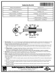
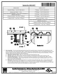
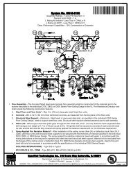
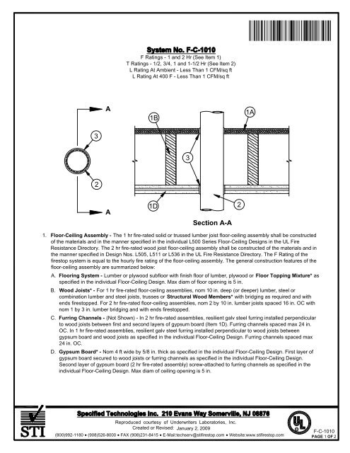
F Ratings - 1 and 2 Hr (See Item 1)<br />
T Ratings - 1/2, 3/4, 1 and 1-1/2 Hr (See Item 2)<br />
L Rating At Ambient - Less Than 1 CFM/sq ft<br />
L Rating At 400 F - Less Than 1 CFM/sq ft<br />
A<br />
1B<br />
1A<br />
3<br />
3<br />
2<br />
A<br />
1D<br />
Section A-A<br />
2<br />
1. Floor-Ceiling Assembly - The 1 hr fire-rated solid or trussed lumber joist floor-ceiling assembly shall be constructed<br />
of the materials and in the manner specified in the individual L500 Series Floor-Ceiling Designs in the UL Fire<br />
Resistance Directory. The 2 hr fire-rated wood joist floor-ceiling assembly shall be constructed of the materials and in<br />
the manner specified in Design Nos. L505, L511 or L536 in the UL Fire Resistance Directory. The F Rating of the<br />
firestop system is equal to the hourly fire rating of the floor-ceiling assembly. The general construction features of the<br />
floor-ceiling assembly are summarized below:<br />
A. Flooring System - Lumber or plywood subfloor with finish floor of lumber, plywood or Floor Topping Mixture* as<br />
specified in the individual Floor-Ceiling Design. Max diam of floor opening is 5 in.<br />
B. Wood Joists* - For 1 hr fire-rated floor-ceiling assemblies, nom 10 in. deep (or deeper) lumber, steel or<br />
combination lumber and steel joists, trusses or Structural Wood Members* with bridging as required and with<br />
ends firestopped. For 2 hr fire-rated floor-ceiling assemblies, nom 2 by 10 in. lumber joists spaced 16 in. OC with<br />
nom 1 by 3 in. lumber bridging and with ends firestopped.<br />
C. Furring Channels - (Not Shown) - In 2 hr fire-rated assemblies, resilient galv steel furring installed perpendicular<br />
to wood joists between first and second layers of gypsum board (Item 1D). Furring channels spaced max 24 in.<br />
OC. In 1 hr fire-rated assemblies, resilient galv steel furring installed perpendicular to wood joists between<br />
gypsum board and wood joists as specified in the individual Floor-Ceiling Design. Furring channels spaced max<br />
24 in. OC.<br />
D. Gypsum Board* - Nom 4 ft wide by 5/8 in. thick as specified in the individual Floor-Ceiling Design. First layer of<br />
gypsum board secured to wood joists or furring channels as specified in the individual Floor-Ceiling Design.<br />
Second layer of gypsum board (2 hr fire-rated assembly) screw-attached to furring channels as specified in the<br />
individual Floor-Ceiling Design. Max diam of ceiling opening is 5 in.<br />
Reproduced courtesy of Underwriters Laboratories, <strong>Inc</strong>.<br />
Created or Revised: January 2, 2009<br />
(800)992-1180 (908)526-8000 FAX (908)231-8415 E-Mail:techserv@stifirestop.com Website:www.stifirestop.com<br />
R<br />
F-C-<strong>1010</strong><br />
PAGE 1 OF 2
2. Through Penetrants - One metallic pipe, conduit or tube installed approximately midway between wood joists. Diam<br />
of openings hole-sawed through flooring system and through gypsum board ceiling to be nom 1/2 in. greater than the<br />
outside diam of through-penetrant. For 1 hr rated floor assemblies, through penetrant to be installed either<br />
concentrically or eccentrically within the opening with an annular space of 0 in. (point contact) to 1/2 in. For 2 hr rated<br />
floor assemblies, through penetrant to be centered in the opening. Pipe, conduit or tube to be rigidly supported on<br />
both sides of floor-ceiling assembly. The following types and sizes of metallic pipes, conduits or tubing may be used:<br />
A. Steel Pipe - Nom 4 in. diam (or smaller) Schedule 5 (or heavier) steel pipe.<br />
B. Iron Pipe - Nom 4 in. diam (or smaller) cast or ductile iron pipe.<br />
C. Conduit - Nom 4 in. diam (or smaller) steel electrical metallic tubing or steel conduit.<br />
D. Copper Pipe - Nom 4 in. diam (or smaller) Regular (or heavier) copper pipe.<br />
E. Copper Tubing - Nom 4 in. diam (or smaller) Type L (or heavier) copper tubing.<br />
The T Rating of the firestop system is dependent upon the hourly rating of the floor-ceiling assembly and type of<br />
through-penetrant used as shown in the table below:<br />
Floor Ceiling Rating Hr<br />
1<br />
1<br />
1<br />
2<br />
2<br />
2<br />
Type of Penetrant<br />
Steel or Iron Pipe<br />
Steel Conduit<br />
Copper Tube or Pipe<br />
Steel or Iron Pipe<br />
Steel Conduit<br />
Copper Tube or Pipe<br />
T Rating Hr<br />
1<br />
1<br />
3/4<br />
1-1/2<br />
1-1/2<br />
1/2<br />
3. Fill, Void or Cavity Material* - Sealant - Fill material forced into annulus to fill space to max extent possible on top<br />
surface of floor and bottom surface of ceiling. Min 3/8 in. diam bead of fill material applied at point contact location on<br />
top surface of floor and on bottom surface of gypsum board ceiling.<br />
SPECIFIED TECHNOLOGIES INC - SpecSeal Series SSS Sealant or SpecSeal LCI Sealant<br />
*Bearing the UL Classification Mark<br />
Reproduced courtesy of Underwriters Laboratories, <strong>Inc</strong>.<br />
Created or Revised: January 2, 2009<br />
(800)992-1180 (908)526-8000 FAX (908)231-8415 E-Mail:techserv@stifirestop.com Website:www.stifirestop.com<br />
R<br />
F-C-<strong>1010</strong><br />
PAGE 2 OF 2