Microcomputers General-purpose I/O
Microcomputers General-purpose I/O
Microcomputers General-purpose I/O

Create successful ePaper yourself
Turn your PDF publications into a flip-book with our unique Google optimized e-Paper software.
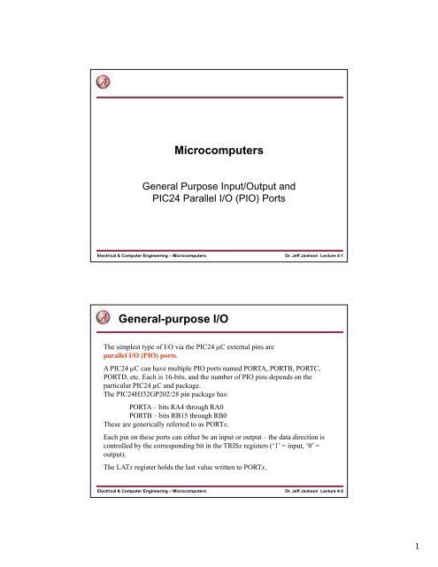
<strong>Microcomputers</strong><br />
<strong>General</strong> Purpose Input/Output and<br />
PIC24 Parallel I/O (PIO) Ports<br />
Electrical & Computer Engineering – <strong>Microcomputers</strong><br />
Dr. Jeff Jackson Lecture 4-1<br />
<strong>General</strong>-<strong>purpose</strong> I/O<br />
The simplest type of I/O via the PIC24 µC external pins are<br />
parallel I/O (PIO) ports.<br />
A PIC24 µC can have multiple PIO ports named PORTA, PORTB, PORTC,<br />
PORTD, etc. Each is 16-bits, and the number of PIO pins depends on the<br />
particular PIC24 µC and package.<br />
The PIC24HJ32GP202/28 pin package has:<br />
PORTA – bits RA4 through RA0<br />
PORTB – bits RB15 through RB0<br />
These are generically referred to as PORTx.<br />
Each pin on these ports can either be an input or output – the data direction is<br />
controlled by the corresponding bit in the TRISx registers (‘1’ = input, ‘0’ =<br />
output).<br />
The LATx register holds the last value written to PORTx.<br />
Electrical & Computer Engineering – <strong>Microcomputers</strong><br />
Dr. Jeff Jackson Lecture 4-2<br />
1
PIC24HJ32GP202 Pin Diagram<br />
Electrical & Computer Engineering – <strong>Microcomputers</strong><br />
Dr. Jeff Jackson Lecture 4-3<br />
PORTB Example<br />
Set the upper 8 bits of PORTB to outputs, lower 8 bits to be inputs:<br />
TRISB = 0x00FF;<br />
Drive RB15, RB13 high;<br />
others low:<br />
PORTB = 0xA000;<br />
Wait until input RB0 is high:<br />
Test returns true while RB0=0<br />
so loop exits when RB0=1<br />
while ((PORTB & 0x0001) == 0);<br />
Wait until input RB3 is low:<br />
while ((PORTB & 0x0008) == 1);<br />
Test returns true while RB3=1<br />
so loop exits when RB3=0<br />
Electrical & Computer Engineering – <strong>Microcomputers</strong><br />
Dr. Jeff Jackson Lecture 4-4<br />
2
PORTB Example (cont.)<br />
Individual PORT bits are named as _RB0, _RB1, .._RA0, etc.<br />
so this can be used in C code.<br />
Test returns true while RB2=0<br />
Wait until input RB2 is high: so loop exits when RB2=1.<br />
Can also be written as:<br />
while (_RB2 == 0);<br />
while (!_RB2);<br />
Wait until input RB3 is low:<br />
while (_RB3 == 1) ;<br />
Test returns true while RB3=1<br />
so loop exits when RB3=0<br />
Can also be written as:<br />
while (_RB3);<br />
Electrical & Computer Engineering – <strong>Microcomputers</strong><br />
Dr. Jeff Jackson Lecture 4-5<br />
Switch Input<br />
PIC24 µC<br />
RB3<br />
Vdd<br />
10K<br />
External pullup<br />
When switch is pressed<br />
RB3 reads as ‘0’, else<br />
reads as ‘1’.<br />
PIC24 µC<br />
RB3<br />
don’t do<br />
this!<br />
If pullup is not present,<br />
then input would float<br />
when switch is not<br />
pressed, and input value<br />
may read as ‘0’ or ‘1’<br />
because of system noise.<br />
Electrical & Computer Engineering – <strong>Microcomputers</strong><br />
Dr. Jeff Jackson Lecture 4-6<br />
3
PORTx Pin Diagram<br />
External pin shared with<br />
other on-chip modules<br />
TRIS bit controls<br />
tristate control on<br />
output driver<br />
Reading LATx reads last<br />
value written; reading<br />
PORTx reads the actual<br />
pin<br />
Electrical & Computer Engineering – <strong>Microcomputers</strong><br />
Dr. Jeff Jackson Lecture 4-7<br />
LATx versus PORTx<br />
Writing LATx is the same as writing PORTx, both writes go to<br />
the latch.<br />
Reading LATx reads the latch output (last value written), while<br />
reading PORTx reads the actual pin value.<br />
PIC24 µC<br />
RB3<br />
Configure RB3 as an open-drain<br />
output, then write a ‘1’ to it.<br />
The physical pin is tied to ground, so<br />
it can never go high.<br />
Reading _RB3 returns a ‘0’, but<br />
reading _LATB3 returns a ‘1’ (the<br />
last value written).<br />
Electrical & Computer Engineering – <strong>Microcomputers</strong><br />
Dr. Jeff Jackson Lecture 4-8<br />
4
LATx versus PORTx (cont)<br />
_LATB0 = 1;<br />
_LATB1 = 1;<br />
Compiler<br />
bset LATB,#0<br />
bset LATB,#1<br />
bitset/bitclr instructions are read/modify/write, in this case, read<br />
LATB, modify contents, write LATB. This works as expected.<br />
_RB0 = 1;<br />
_RB1 = 1;<br />
Compiler<br />
bset PORTB,#0<br />
bset PORTB,#1<br />
bset/bclr instructions are read/modify/write – in this case, read<br />
PORTB, modify its contents, then write PORTB. Because of<br />
pin loading and fast internal clock speeds, the second bset may<br />
not work correctly! (see datasheet explanation). For this reason,<br />
our examples use LATx when writing to a pin.<br />
Electrical & Computer Engineering – <strong>Microcomputers</strong><br />
Dr. Jeff Jackson Lecture 4-9<br />
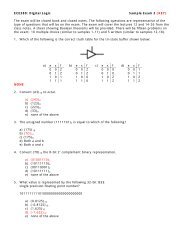
Aside: Tri-State Buffer (TSB) Review<br />
A tri-state buffer (TSB) has input, output, and outputenable<br />
(OE) pins. Output can either be ‘1’, ‘0’ or ‘Z’<br />
(high impedance).<br />
A<br />
OE<br />
Y<br />
A<br />
OE<br />
Y<br />
OE = 0, then switch closed<br />
OE = 1, then switch open<br />
Electrical & Computer Engineering – <strong>Microcomputers</strong><br />
Dr. Jeff Jackson Lecture 4-10<br />
5
Schmitt Trigger Input Buffer<br />
Each PIO input has a Schmitt trigger input buffer; this<br />
transforms slowly rising/falling input transitions into sharp<br />
rising/falling transitions internally.<br />
Electrical & Computer Engineering – <strong>Microcomputers</strong><br />
Dr. Jeff Jackson Lecture 4-11<br />
PORTx Shared Pin Functions<br />
External pins are shared with other on-chip modules. Just<br />
setting _TRISx = 1 may be not be enough to configure a<br />
PORTx pin as an input, depending on what other modules share<br />
the pin:<br />
RB15 shared with AN9, which is<br />
an analog input to the on-chip<br />
Analog-to-Digital Converter<br />
(ADC). Must disable analog<br />
functionality!<br />
_PCFG9 = 1; Disables analog function<br />
_TRISB15 = 1; Configure as input<br />
_PCFG9 = 1;<br />
_TRISB15 = 0;<br />
Disables analog function<br />
Configure as output<br />
Electrical & Computer Engineering – <strong>Microcomputers</strong><br />
Dr. Jeff Jackson Lecture 4-12<br />
6
Analog/Digital Pin versus Digital-only Pin<br />
Pins with shared analog/digital functions have a maximum input<br />
voltage of Vdd + 0.3 V, so 3.6 V<br />
Pins with no analog functions ( “digital-only” pins) are 5 V<br />
tolerant, their maximum input voltage is 5.6 V.<br />
This is handy for receiving digital inputs from 5V parts.<br />
Most PIO pins can only source or sink a maximum 4 mA. You<br />
may damage the output pin if you tie a load that tries to<br />
sink/source more than this current.<br />
Electrical & Computer Engineering – <strong>Microcomputers</strong><br />
Dr. Jeff Jackson Lecture 4-13<br />
Internal Weak Pullups<br />
External pins with a CNy pin function have a weak internal<br />
pullup that can be enabled or disabled. Change notification input; to<br />
enable pullup:<br />
CN11PUE = 1;<br />
To disable pullup:<br />
CN11PUE = 0;<br />
Electrical & Computer Engineering – <strong>Microcomputers</strong><br />
Dr. Jeff Jackson Lecture 4-14<br />
7
Open Drain Outputs<br />
Each PIO pin can be configured as an open drain output, which<br />
means the pullup transistor is disabled.<br />
_ODCxy = 1 enables open drain, _ODCxy = 0 disables open drain<br />
_ODCB15 = 1;<br />
Enables open drain on RB15<br />
Electrical & Computer Engineering – <strong>Microcomputers</strong><br />
Dr. Jeff Jackson Lecture 4-15<br />
Port Configuration Macros<br />
For convenience, we supply macros/inline functions that hide pin<br />
configuration details:<br />
CONFIG_RB15_AS_DIG_OUTPUT();<br />
CONFIG_RB15_AS_DIG_INPUT();<br />
These macros are supplied for each port pin. Because these<br />
functions change depending on the particular PIC24 µC, the<br />
include/devices directory has a include file for each PIC24 µC,<br />
and the correct file is included by the include/pic24_ports.h file.<br />
Electrical & Computer Engineering – <strong>Microcomputers</strong><br />
Dr. Jeff Jackson Lecture 4-16<br />
8
Other Port Configuration Macros<br />
Other macros are provided for pull-up and open drain configuration:<br />
ENABLE_RB15_PULLUP();<br />
DISABLE_RB15_PULLUP();<br />
ENABLE_RB13_OPENDRAIN();<br />
DISABLE_RB13_OPENDRAIN();<br />
CONFIG_RB8_AS_DIG_OD_OUTPUT();<br />
Output + Open<br />
drain config in<br />
one macro<br />
<strong>General</strong> forms are ENABLE_Rxy_PULLUP(),<br />
DISABLE_Rxy_PULLUP(), ENABLE_Rxy_OPENDRAIN(),<br />
DISABLE_Rxy_OPENDRAIN(),<br />
CONFIG_Rxy_AS_DIG_OD_OUTPUT()<br />
A port may not have a pull-up if it does not share the pin with a<br />
change notification input, in this case, the macro does not exist and<br />
you will get an error message when you try to compile the code.<br />
Electrical & Computer Engineering – <strong>Microcomputers</strong><br />
Dr. Jeff Jackson Lecture 4-17<br />
ledflash.c<br />
Electrical & Computer Engineering – <strong>Microcomputers</strong><br />
Dr. Jeff Jackson Lecture 4-18<br />
9
LED/Switch IO: Count number of press/releases<br />
Electrical & Computer Engineering – <strong>Microcomputers</strong><br />
Dr. Jeff Jackson Lecture 4-19<br />
I/O Configuration<br />
Use macros to isolate pin assignments for physical devices so that it is<br />
easy to change code if (WHEN!) the pin assignments change!<br />
Electrical & Computer Engineering – <strong>Microcomputers</strong><br />
Dr. Jeff Jackson Lecture 4-20<br />
10
Counting # of Press/Releases<br />
Copyright Delmar Cengage Learning 2008. All Rights Reserved.<br />
From: Reese/Bruce/Jones, “Microcontrollers: From Assembly to C with the PIC24 Family”.<br />
Electrical & Computer Engineering – <strong>Microcomputers</strong><br />
Dr. Jeff Jackson Lecture 4-21<br />
State Machine I/O<br />
Copyright Delmar Cengage Learning 2008. All Rights Reserved.<br />
From: Reese/Bruce/Jones, “Microcontrollers: From Assembly to C with the PIC24 Family”.<br />
Electrical & Computer Engineering – <strong>Microcomputers</strong><br />
Dr. Jeff Jackson Lecture 4-22<br />
11
C Code Solution<br />
Electrical & Computer Engineering – <strong>Microcomputers</strong><br />
Dr. Jeff Jackson Lecture 4-23<br />
C Code Solution (cont).<br />
}<br />
Electrical & Computer Engineering – <strong>Microcomputers</strong><br />
Dr. Jeff Jackson Lecture 4-24<br />
12
A More Complex Problem<br />
Electrical & Computer Engineering – <strong>Microcomputers</strong><br />
Dr. Jeff Jackson Lecture 4-25<br />
Solution, Part 1<br />
Copyright Delmar Cengage Learning 2008. All Rights Reserved.<br />
From: Reese/Bruce/Jones, “Microcontrollers: From Assembly to C with the PIC24 Family”.<br />
Electrical & Computer Engineering – <strong>Microcomputers</strong><br />
Dr. Jeff Jackson Lecture 4-26<br />
13
Solution, Part 2<br />
Electrical & Computer Engineering – <strong>Microcomputers</strong><br />
Dr. Jeff Jackson Lecture 4-27<br />
Console Output for LED/SW Problem<br />
Electrical & Computer Engineering – <strong>Microcomputers</strong><br />
Dr. Jeff Jackson Lecture 4-28<br />
14
What do you have to know?<br />
• GPIO port usage of PORTA, PORTB<br />
• How to use the weak pullups of PORTB<br />
• Definition of Schmitt Trigger<br />
• How a Tri-state buffer works<br />
• How an open-drain output works and what it is<br />
useful for.<br />
• How to write C code for finite state machine<br />
description of LED/Switch IO.<br />
Electrical & Computer Engineering – <strong>Microcomputers</strong><br />
Dr. Jeff Jackson Lecture 4-29<br />
15