Download the Fastrack Super Duty Owner's Manual 48/54/60
Download the Fastrack Super Duty Owner's Manual 48/54/60
Download the Fastrack Super Duty Owner's Manual 48/54/60

Create successful ePaper yourself
Turn your PDF publications into a flip-book with our unique Google optimized e-Paper software.
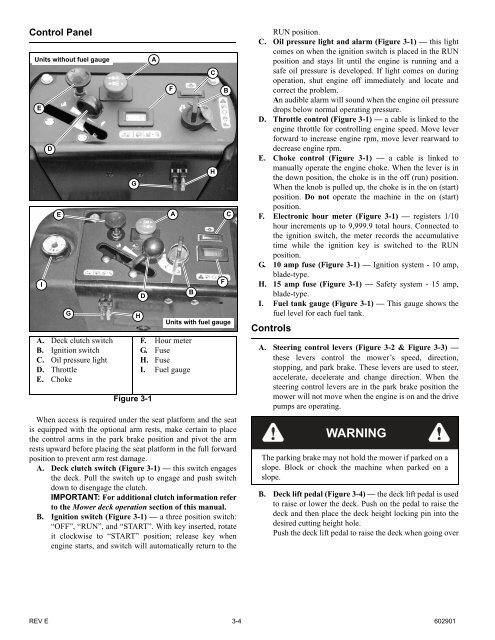
Control Panel<br />
Units without fuel gauge<br />
E<br />
I<br />
D<br />
E<br />
G<br />
A. Deck clutch switch<br />
B. Ignition switch<br />
C. Oil pressure light<br />
D. Throttle<br />
E. Choke<br />
G<br />
Figure 3-1<br />
F. Hour meter<br />
G. Fuse<br />
H. Fuse<br />
I. Fuel gauge<br />
When access is required under <strong>the</strong> seat platform and <strong>the</strong> seat<br />
is equipped with <strong>the</strong> optional arm rests, make certain to place<br />
<strong>the</strong> control arms in <strong>the</strong> park brake position and pivot <strong>the</strong> arm<br />
rests upward before placing <strong>the</strong> seat platform in <strong>the</strong> full forward<br />
position to prevent arm rest damage.<br />
A. Deck clutch switch (Figure 3-1) — this switch engages<br />
<strong>the</strong> deck. Pull <strong>the</strong> switch up to engage and push switch<br />
down to disengage <strong>the</strong> clutch.<br />
IMPORTANT: For additional clutch information refer<br />
to <strong>the</strong> Mower deck operation section of this manual.<br />
B. Ignition switch (Figure 3-1) — a three position switch:<br />
“OFF”, “RUN”, and “START”. With key inserted, rotate<br />
it clockwise to “START” position; release key when<br />
engine starts, and switch will automatically return to <strong>the</strong><br />
H<br />
D<br />
A<br />
F<br />
A<br />
B<br />
C<br />
H<br />
F<br />
B<br />
C<br />
Units with fuel gauge<br />
RUN position.<br />
C. Oil pressure light and alarm (Figure 3-1) — this light<br />
comes on when <strong>the</strong> ignition switch is placed in <strong>the</strong> RUN<br />
position and stays lit until <strong>the</strong> engine is running and a<br />
safe oil pressure is developed. If light comes on during<br />
operation, shut engine off immediately and locate and<br />
correct <strong>the</strong> problem.<br />
An audible alarm will sound when <strong>the</strong> engine oil pressure<br />
drops below normal operating pressure.<br />
D. Throttle control (Figure 3-1) — a cable is linked to <strong>the</strong><br />
engine throttle for controlling engine speed. Move lever<br />
forward to increase engine rpm, move lever rearward to<br />
decrease engine rpm.<br />
E. Choke control (Figure 3-1) — a cable is linked to<br />
manually operate <strong>the</strong> engine choke. When <strong>the</strong> lever is in<br />
<strong>the</strong> down position, <strong>the</strong> choke is in <strong>the</strong> off (run) position.<br />
When <strong>the</strong> knob is pulled up, <strong>the</strong> choke is in <strong>the</strong> on (start)<br />
position. Do not operate <strong>the</strong> machine in <strong>the</strong> on (start)<br />
position.<br />
F. Electronic hour meter (Figure 3-1) — registers 1/10<br />
hour increments up to 9,999.9 total hours. Connected to<br />
<strong>the</strong> ignition switch, <strong>the</strong> meter records <strong>the</strong> accumulative<br />
time while <strong>the</strong> ignition key is switched to <strong>the</strong> RUN<br />
position.<br />
G. 10 amp fuse (Figure 3-1) — Ignition system - 10 amp,<br />
blade-type.<br />
H. 15 amp fuse (Figure 3-1) — Safety system - 15 amp,<br />
blade-type.<br />
I. Fuel tank gauge (Figure 3-1) — This gauge shows <strong>the</strong><br />
fuel level for each fuel tank.<br />
Controls<br />
A. Steering control levers (Figure 3-2 & Figure 3-3) —<br />
<strong>the</strong>se levers control <strong>the</strong> mower’s speed, direction,<br />
stopping, and park brake. These levers are used to steer,<br />
accelerate, decelerate and change direction. When <strong>the</strong><br />
steering control levers are in <strong>the</strong> park brake position <strong>the</strong><br />
mower will not move when <strong>the</strong> engine is on and <strong>the</strong> drive<br />
pumps are operating.<br />
WARNING<br />
The parking brake may not hold <strong>the</strong> mower if parked on a<br />
slope. Block or chock <strong>the</strong> machine when parked on a<br />
slope.<br />
B. Deck lift pedal (Figure 3-4) — <strong>the</strong> deck lift pedal is used<br />
to raise or lower <strong>the</strong> deck. Push on <strong>the</strong> pedal to raise <strong>the</strong><br />
deck and <strong>the</strong>n place <strong>the</strong> deck height locking pin into <strong>the</strong><br />
desired cutting height hole.<br />
Push <strong>the</strong> deck lift pedal to raise <strong>the</strong> deck when going over<br />
REV E 3-4 <strong>60</strong>2901