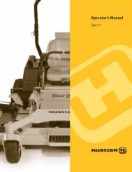
Download the Fastrack Super Duty Owner's Manual 48/54/60
Download the Fastrack Super Duty Owner's Manual 48/54/60
Download the Fastrack Super Duty Owner's Manual 48/54/60

Create successful ePaper yourself
Turn your PDF publications into a flip-book with our unique Google optimized e-Paper software.
Clutch life will be maximized if <strong>the</strong>se procedures are<br />
followed.<br />
1. Engage <strong>the</strong> clutch only when <strong>the</strong> throttle is set at<br />
approximately 2/3 throttle and <strong>the</strong>re is no load on <strong>the</strong><br />
blades. After clutch engagement, advance <strong>the</strong> engine<br />
throttle to full rpm.<br />
Engaging <strong>the</strong> deck clutch at high engine rpm or when<br />
under heavy load (in tall grass, for example) can cause<br />
belts and/or electric clutch to slip, resulting in premature<br />
wear or possible damage.<br />
2. Disengage <strong>the</strong> clutch only when <strong>the</strong> throttle is set at less<br />
than 1/2 throttle.<br />
Never disengage <strong>the</strong> clutch with <strong>the</strong> engine running at<br />
high rpm. Setting <strong>the</strong> throttle to less than 1/2 throttle<br />
when disengaging <strong>the</strong> clutch will help extend clutch life.<br />
Warranty will not be allowed for deck clutches that fail due<br />
to improper engagement and disengagement practices.<br />
Deck Cutting Height Adjustment<br />
Transport lever<br />
Pin<br />
Figure 3-11<br />
Cutting height holes<br />
Deck cutting height is adjustable in 1/4” (6.4mm) increments.<br />
The holes in <strong>the</strong> height adjusting bar are spaced at 1/2”<br />
(12.7mm) intervals. By turning <strong>the</strong> height adjusting stop around,<br />
1/4” (6.4mm) increments can be attained due to <strong>the</strong> 1/4”<br />
(6.4mm) plate that is part of <strong>the</strong> stop. Figure 3-11<br />
EXAMPLE: When <strong>the</strong> height adjusting stop is placed in <strong>the</strong><br />
3” (76.2mm) hole, with <strong>the</strong> 1/4” (6.4mm) plate facing to <strong>the</strong><br />
front of <strong>the</strong> unit, <strong>the</strong> cutting height is at 3” (76.2mm). When <strong>the</strong><br />
height adjusting stop is placed in <strong>the</strong> 3” (76.2mm) hole, with<br />
<strong>the</strong> 1/4” (6.4mm) plate on <strong>the</strong> operator’s side of <strong>the</strong> hole, <strong>the</strong><br />
cutting height is at 3-1/4” (82.6mm).<br />
The notch located at <strong>the</strong> rear of <strong>the</strong> height adjusting bar<br />
engages <strong>the</strong> stop handle when <strong>the</strong> deck lift pedal is fully<br />
depressed. This sets <strong>the</strong> deck in transport mode.<br />
Anti-scalp<br />
wheel<br />
Anti-Scalp Wheels<br />
Anti-scalp wheels are standard on FasTrak <strong>Super</strong> <strong>Duty</strong> <strong>48</strong>/<strong>54</strong>/<br />
<strong>60</strong> units. These anti-scalp wheels are designed to minimize<br />
scalping when mowing on rough uneven terrain. Figure 3-12<br />
Anti-scalp wheels can be installed in two positions. With <strong>the</strong><br />
wheel installed in <strong>the</strong> bottom hole, <strong>the</strong> wheel is located 2”<br />
(50.8mm) below <strong>the</strong> mower blades. This setting is preferred<br />
when mowing at cutting heights of 2-1/2” (63.5mm) or higher.<br />
When <strong>the</strong> wheel is mounted in <strong>the</strong> top hole, it is located 1”<br />
(25.4mm) below <strong>the</strong> mower blades. This is <strong>the</strong> acceptable<br />
setting for mowing at cutting heights of 1-1/2” (38.1mm) or<br />
higher.<br />
Adjusting<br />
holes<br />
Figure 3-12<br />
REV E 3-12 <strong>60</strong>2901