Resistive Float Fuel Senders EIS
Resistive Float Fuel Senders EIS
Resistive Float Fuel Senders EIS

Create successful ePaper yourself
Turn your PDF publications into a flip-book with our unique Google optimized e-Paper software.
Calibrating <strong>Resistive</strong> <strong>Float</strong>-Type <strong>Fuel</strong> <strong>Senders</strong><br />
<strong>EIS</strong> and Sport EFIS Manual Supplement<br />
Revision A1<br />
07-Aug-2013
Calibration of <strong>Float</strong>-Type <strong>Resistive</strong> <strong>Fuel</strong> <strong>Senders</strong> for <strong>EIS</strong> & Sport<br />
GRT Avionics<br />
Supplement Revision Notes<br />
Revision Date Change Description<br />
A 28-Jun-2013 Initial Release<br />
A1 07-Aug-2013 Corrected formula in Worksheet 2, Step 5 (scale factor calculation)<br />
2 Revision A1
Calibration of <strong>Float</strong>-Type <strong>Resistive</strong> <strong>Fuel</strong> <strong>Senders</strong> for <strong>EIS</strong> & Sport<br />
GRT Avionics<br />
Table of Contents<br />
Section 1: Introduction<br />
1.1 About <strong>Float</strong>-Type <strong>Resistive</strong> <strong>Fuel</strong> <strong>Senders</strong>………………………………………………………………….. 4<br />
1.2 Data Port and Hardware Requirements……………………………………………………………………. 4<br />
Section 2: Installation & Wiring Using the <strong>EIS</strong><br />
2.1 Mechanical Installation……………………………………………………………………………………………. 6<br />
2.2 Assigning Aux Inputs in <strong>EIS</strong>………………………………………………………………………………………. 6<br />
2.3 Wiring <strong>EIS</strong> and <strong>Senders</strong>…………………………………………………………………………………………….. 7<br />
2.4 Sport EFIS <strong>Fuel</strong> Sender Calibration Options………………….…………………………………………. 7<br />
Section 3: <strong>EIS</strong> Setup & Programming<br />
3.1 Set Up <strong>EIS</strong> Auxiliaries…………..……………………………………………………………………………………. 8<br />
3.2 Calibrate <strong>Fuel</strong> <strong>Senders</strong> and <strong>EIS</strong>….….…………….……………………………………………………………. 9<br />
Section 4: Set Up EFIS <strong>Fuel</strong> Gauge Display (<strong>EIS</strong> Aux Inputs)<br />
4.1 Configure EFIS <strong>Fuel</strong> Bar Graphs……….………………………………………………………………………. 11<br />
3 Revision A1
GRT Avionics<br />
Calibration of <strong>Float</strong>-Type <strong>Resistive</strong> <strong>Fuel</strong> <strong>Senders</strong> for <strong>EIS</strong> & Sport<br />
Section 1: Introduction<br />
1.1 About <strong>Resistive</strong> <strong>Float</strong> <strong>Senders</strong><br />
When aviation was new, fuel gauges consisted of a cork float connected to a wire shaped like an<br />
upside down L that ran up and out through a fuel cap visible to the pilot. The concept was simple:<br />
The cork floated on top of the fuel. As the fuel tank went from full to empty, the cork descended<br />
with the fuel level, causing the wire to slide down. When the upside down L rested on the cap, the<br />
cork was at its lowest, and tank was presumably empty.<br />
<strong>Resistive</strong> float senders are an electronic upgrade to this concept. The float is still there, but its rise<br />
or fall causes tiny changes in voltage which drive a fuel gauge instrument–In this case, an <strong>EIS</strong> or<br />
EFIS display.<br />
The gauge, in this case the <strong>EIS</strong> unit, measures the voltage that comes out of the sender unit. Voltage<br />
enters the sender unit from the <strong>EIS</strong> as an “excitation” current. It passes through a resistor that cuts<br />
the voltage down to a consistent, known voltage level. As the float moves up and down along a<br />
slide contact, the electrical current flows through a variable resistor that further changes the voltage.<br />
The <strong>EIS</strong> then reads the voltage levels flowing from the senders. The sender and <strong>EIS</strong> must be<br />
calibrated so that the float position voltage readings can be converted into pilot-friendly readings<br />
of gallons or liters.<br />
1.2 Data Port and Hardware Requirements<br />
<strong>EIS</strong> Data Port<br />
Power Connections<br />
Hardware Required<br />
Requires (1) AUX function per fuel tank sender.*<br />
Power is provided from the <strong>EIS</strong> unit.<br />
(1) float sender per fuel tank<br />
(1) 470 ohm (¼-½ watt) resistor per sender; available from GRT,<br />
Radio Shack or other electronics supply source<br />
*NOTE: <strong>EIS</strong> Model 2000 units have two user-definable Aux inputs. <strong>EIS</strong> Model 4000/6000/9000<br />
units have 6 user-definable Aux inputs. Any of these can be used for fuel senders.<br />
Revision A1 4
Calibration of <strong>Float</strong>-Type <strong>Resistive</strong> <strong>Fuel</strong> <strong>Senders</strong> for <strong>EIS</strong> & Sport<br />
GRT Avionics<br />
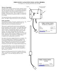
<strong>Fuel</strong> Tank<br />
Variable Resistor<br />
<strong>Float</strong><br />
How Does It Work?<br />
The Variable Resistor and float stem are wired to<br />
send a signal to the fuel gauge in the form of a<br />
precise level of voltage that depends on the<br />
position of the float. As the float rises, the voltage<br />
of the signal changes. Most of the time, the signal<br />
voltage is the lowest when the tank is empty, and<br />
the highest when it is full. (Not always-sometimes<br />
the opposite is true. This is where the<br />
Forward/Reverse Sensing adjustment will come<br />
into play later in this process.)<br />
<strong>Float</strong><br />
Converting Voltage to Gauge Readings<br />
The voltage level created by the float position is<br />
sensed by the <strong>EIS</strong>. But we don’t care about voltage<br />
levels, we care about gallons (or litres) in the tank.<br />
This is where Scale Factor comes in. The voltage<br />
range is somewhere between 0 and 5. If the <strong>EIS</strong><br />
senses 1 volt, where is the float position? How<br />
many gallons does 1 volt represent? Scale factor<br />
converts raw voltage to a value we can use on the<br />
<strong>EIS</strong>. This is done by calibrating the system. Horizon<br />
EFIS users can take advantage of automatic<br />
calculations by the EFIS to simplify the calibration<br />
process.<br />
“FULL” in reality<br />
“FULL” on gauge<br />
<strong>Float</strong><br />
<strong>Float</strong> Sender Limitations<br />
Sometimes the float hits the top of the fuel tank<br />
before the tank is full. This causes the gauge to<br />
read FULL when the tank is not truly full. Airplanes<br />
with dihedral run into this problem often because<br />
there is much more fuel uphill from the float. The<br />
same is true when it reads empty. Usually there is<br />
a small amount of fuel that remains in the tank<br />
when the float is at its lowest position. Irregularlyshaped<br />
tanks provide unique calibration challenges<br />
because the relationship of quantity to float<br />
position is not linear- The tank may contain more<br />
or less fuel at certain float levels. That’s why it’s<br />
important to add fuel in many small increments<br />
while calibrating the fuel senders to get a more<br />
accurate picture of reality.<br />
5 Revision A1
Calibration of <strong>Float</strong>-Type <strong>Resistive</strong> <strong>Fuel</strong> <strong>Senders</strong> for <strong>EIS</strong> & Sport<br />
GRT Avionics<br />
Section 2: Installation & Wiring<br />
2.1 Mechanical Installation<br />
Every airplane is different, so mechanical installation of senders is not covered in this Supplement.<br />
Use the airplane kit and/or sender instructions to properly install each sender.<br />
2.2 Assigning Aux Inputs in the <strong>EIS</strong><br />
<strong>Fuel</strong> senders wired to the <strong>EIS</strong> utilize the Auxiliary (Aux) functions. These are user-configurable data<br />
ports that can be used for a wide variety of sensors. They are labeled AX1, AX2, etc. and are found<br />
on <strong>EIS</strong> pages 12 and 13. (We call them “Aux” functions but the <strong>EIS</strong> label skips the “u” to save space.)<br />
Start your installation by deciding which Auxiliary inputs you will use for your fuel senders. If you<br />
are planning to mount the <strong>EIS</strong> in view on the instrument panel, keep in mind the position of the<br />
auxiliary input functions on the various <strong>EIS</strong> “pages”. Referring to figure 1b in the <strong>EIS</strong> installation<br />
manual, you will note that Aux 1, 2, & 3 appear on page 12, and Aux 4, 5 and 6* appear on page<br />
13. It is advisable to wire the fuel senders to two Aux inputs that are on the same page. For example,<br />
Left Tank on Aux 1, Right Tank on Aux 2, and <strong>Fuel</strong> Flow on Aux 3.<br />
You may fill in the My System table below to record the Aux inputs and other information for each<br />
sender to aid in creating your wiring diagram or schematic for your airplane. Refer to Figure 5a,<br />
Connector A wiring diagram, in the <strong>EIS</strong> manual to find pin assignments and suggested wire colors.<br />
This will come in handy later on if it becomes necessary to troubleshoot.<br />
*Model 2000 units have only 2 Aux inputs. Model 4000/6000 units with software versions prior to<br />
xxx46 only have 4 Aux inputs unless otherwise noted on the <strong>EIS</strong> data tag.<br />
My System- <strong>Fuel</strong> Sender Wiring Information<br />
<strong>Fuel</strong> Tank <strong>EIS</strong> AX Input <strong>EIS</strong> Pin Wire Color Notes<br />
– – A25 Blue 4.8V Excitation Output<br />
6 Revision A1
Calibration of <strong>Float</strong>-Type <strong>Resistive</strong> <strong>Fuel</strong> <strong>Senders</strong> for <strong>EIS</strong> & Sport<br />
GRT Avionics<br />
2.3 Wiring the <strong>EIS</strong> and <strong>Senders</strong><br />
Follow the instructions presented in Section 5.2 of the <strong>EIS</strong> installation manual for wiring the <strong>EIS</strong><br />
and its components. Wire the senders to the <strong>EIS</strong> using standard aircraft wiring practices. The general<br />
schematic for float-type fuel senders looks like this. The black dots represent wire splices. Follow<br />
the instructions for the senders to ensure that they are properly grounded.<br />
AX2<br />
Sender 2<br />
<strong>EIS</strong><br />
4.8V Excitation<br />
470 ohm resistors<br />
AX1<br />
Sender 1<br />
2.4 Sport EFIS <strong>Fuel</strong> Sender Calibration Options<br />
The Sport EFIS does not have Analog inputs, so Sport users must wire the fuel senders to the <strong>EIS</strong><br />
Aux inputs. However, if you have a Sport, you do not have to calibrate the senders using the <strong>EIS</strong>.<br />
You have the option to send the raw voltage data from the sender over the <strong>EIS</strong>-EFIS serial<br />
connection, using internal EFIS calculations to calibrate the senders instead. This method will<br />
eliminate the math necessary for <strong>EIS</strong> calibration described in the next few pages. However, it will<br />
also keep the <strong>EIS</strong> Aux fuel quantity readouts in raw format, so it is mainly recommended for builders<br />
who have chosen to blind-mount their <strong>EIS</strong> behind the instrument panel.<br />
To calibrate your senders using the Sport: After wiring the senders as described in Section 2 of<br />
this manual, skip ahead to Section 3.2 of the<br />
for instructions on calibrating the fuel senders. Disregard Sections 3 and 4 of this<br />
manual.<br />
7 Revision A1
Calibration of <strong>Float</strong>-Type <strong>Resistive</strong> <strong>Fuel</strong> <strong>Senders</strong> for <strong>EIS</strong> & Sport<br />
GRT Avionics<br />
Section 3: <strong>EIS</strong> Setup & Programming<br />
3.1 Set Up <strong>EIS</strong> Auxiliaries for <strong>Fuel</strong> <strong>Senders</strong><br />
To access <strong>EIS</strong> configuration menu: Press and hold Center and Right buttons. The “Save Lean<br />
Point?” page will appear initially, but keep holding the buttons until they disappear and the first<br />
configuration page appears.<br />
1. Optional: Refer to Section 7.1.1 in the <strong>EIS</strong> manual to create custom labels for the fuel tank Aux<br />
inputs (such as LF for Left <strong>Fuel</strong>, RF for Right <strong>Fuel</strong>).<br />
2. Decide if you would like to display fuel with a resolution of 0.1 (decimal) or 1 (integer). We<br />
generally recommend a resolution of 1 for fuel tanks, however, some <strong>EIS</strong> 2000 Aux resolutions<br />
are preset to display decimals. See Section 7.1.6 of the <strong>EIS</strong> manual for instructions on how to set<br />
up the Aux resolutions.<br />
3. Choose one tank to begin. For our example, we will use Aux 1 as the Left Tank and Aux 2 as<br />
the Right Tank.<br />
4. Access the <strong>EIS</strong> configuration menu. Press NEXT until you see 1SF. This is the Scale Factor for Aux<br />
1, the left fuel tank in our example. Press UP key to set 1SF to 100.<br />
5. Press NEXT key until you see 1OFF. This is the Aux 1 offset. Set 1OFF to 0.<br />
6. Press NEXT key until you see +/- in the upper left corner of the <strong>EIS</strong> screen. This is the<br />
Forward/Reverse sensing we mentioned on Page 5 of this supplement. The symbols in the line<br />
represent all of the Aux functions, from 1-6, left to right. For now, set the first two symbols in the<br />
line to +. This means Aux 1 and Aux 2 are set to Forward sensing. (See Section 7.1.5 in the <strong>EIS</strong><br />
manual for more on this.)<br />
7. Press and hold the Center and Right keys on the <strong>EIS</strong> to roll quickly through the rest of the settings<br />
and exit the Configuration Pages. If the sender is wired correctly, Aux 1 should now read<br />
something other than zero, as the voltage from the sender is now being read by the <strong>EIS</strong>.<br />
8. Repeat Steps 4 and 5 above for the right tank, if applicable (Aux 2 in our example).<br />
8 Revision A1
GRT Avionics<br />
Calibration of <strong>Float</strong>-Type <strong>Resistive</strong> <strong>Fuel</strong> <strong>Senders</strong> for <strong>EIS</strong> & Sport<br />
3.2 Calibrate <strong>Fuel</strong> <strong>Senders</strong><br />
Preparation: Begin with empty fuel tanks. This operation is easiest to accomplish with a helper to<br />
watch the <strong>EIS</strong> readout. Have a fitting with a rubber hose handy for easy draining of fuel into an<br />
approved fuel container. (Most fuel tank sumps can be unscrewed and replaced with a fitting for<br />
easy draining.) Level the aircraft so that it sits on the ground at an angle close to a straight & level<br />
cruise flight attitude to provide the most accurate fuel level reading in flight.<br />
NOTE: Due to the limitations of float senders described in Section 1.1 of this manual, it is not<br />
recommended to use the tank capacity as the “FULL” indication. The <strong>EIS</strong> should read the actual<br />
fuel level at the upper range limit of the float sender. For example, in a 15 gallon tank, the float<br />
sender may reach its upper limit at 12 gallons. When more than 12 gallons are in the tank, the <strong>EIS</strong><br />
will display 12; however, the gauge will read more accurately below 12 gallons, where sharper<br />
accuracy is most desired.<br />
1. Fill a clean fuel can (5 gallons will work for most kitplanes) with a known quantity of fuel. Record<br />
this quantity in Worksheet 1. Empty the can into the first tank to be calibrated; in this example,<br />
we’ll use Aux 1, Left Tank. The fuel level at this stage must be enough to raise the float off the<br />
bottom stop.<br />
2. Notice the numbers displayed on the <strong>EIS</strong> Aux 1 reading. As the float rises, the number should<br />
increase in value. If it decreases in value as fuel quantity increases, repeat Step 6 in Section 3.1<br />
and set Aux 1 to Reverse Sensing.<br />
3. Anytime after the float begins to rise, drain the fuel from the tank, paying close attention to the<br />
point at which the <strong>EIS</strong> readout stops moving. This means the float is at the bottom of its range.<br />
Note the amount of fuel left in the tank at this point and write it in Worksheet 1. This will become<br />
your “reserve” fuel amount that is in the tank after the gauge reads zero.<br />
4. Write the lower-limit float sender value as shown on the <strong>EIS</strong> Aux 1 on Worksheet 2, Line 1.<br />
5. After the original “known quantity” is all back in the tank, add to it, preferably using a metered<br />
fuel pump or dispenser marked in one-gallon/liter increments. Slowly fill the tank until the <strong>EIS</strong><br />
Aux 1 readout stops changing. This is the upper limit of the float sender. Note the amount of fuel<br />
in the tank at this time and write it in Worksheet 2, Line 4. This quantity will be used as your FULL<br />
fuel gauge reading.<br />
6. Write the upper float sender value as shown on the <strong>EIS</strong> Aux 1 in Worksheet 2, Line 2.<br />
7. Keep filling the tank to capacity and note the quantity difference between the upper limit of the<br />
fuel sender and the actual full quantity. Record it in Worksheet 1. This value will be useful for<br />
flight planning and documenting the actual quantity of the tank.<br />
8. Use Worksheets 1-3 on the next page to determine Scale Factor and Offset values for Aux 1, then<br />
program these values into the <strong>EIS</strong>. The <strong>EIS</strong> should now show an accurate fuel quantity in gallons<br />
or liters. Repeat Steps 1-8 for the other fuel tank(s).<br />
Revision A1 9
Calibration of <strong>Float</strong>-Type <strong>Resistive</strong> <strong>Fuel</strong> <strong>Senders</strong> for <strong>EIS</strong> & Sport<br />
GRT Avionics<br />
Worksheet 1: General Notes<br />
Left<br />
Tank<br />
Center<br />
Tank<br />
Right<br />
Tank<br />
Known quantity of fuel in container<br />
<strong>Fuel</strong> qty remaining below lower float limit<br />
<strong>Fuel</strong> qty added after upper float limit<br />
Worksheet 2: Calculate Scale Factor (AuxSF)<br />
Left<br />
Tank<br />
Center<br />
Tank<br />
Right<br />
Tank<br />
1 <strong>EIS</strong> Empty Reading<br />
2 <strong>EIS</strong> Full Reading<br />
3 RANGE= (Line 2) - (Line 1)<br />
4 <strong>Fuel</strong> QTY (gal or L) at upper limit of float sender<br />
5 Divide Quantity by Range; (Line 4)÷(Line 3)<br />
6 AuxSF = (Line 5) x 100.<br />
Round to nearest whole number.<br />
Worksheet 3: Calculate Auxiliary Offset (AuxOff)<br />
Left<br />
Tank<br />
Center<br />
Tank<br />
Right<br />
Tank<br />
7 (Line 1) x (Line 5); Round to nearest whole number.<br />
Multiply this by 10 if the Aux resolution is 0.1<br />
(decimal reading instead of integer)<br />
8 (Line 7) x 2<br />
9 AuxOff = (Line 8) - 1<br />
Note: Must be an odd number.<br />
10 Revision A1
Calibration of <strong>Float</strong>-Type <strong>Resistive</strong> <strong>Fuel</strong> <strong>Senders</strong> for <strong>EIS</strong> & Sport<br />
GRT Avionics<br />
Section 4: Set Up EFIS <strong>Fuel</strong> Gauge Display (<strong>EIS</strong> Aux Inputs)<br />
4.1 Configure EFIS <strong>Fuel</strong> Bar Graphs<br />
The EFIS engine page is configurable for many instrument display options. In this step, you will<br />
program it to show fuel quantity for each tank on a bar graph. This bar graph will appear on the<br />
ENG page and on the PFD or Map “split screen” views. On the HXr, you can also program one of<br />
the PFD engine dials to show fuel quantity for one or all tanks.<br />
1. Go to the main menu of the Set Menu page. Scroll to and select Graphical Engine Display.<br />
2. Scroll down toward the middle of the page until you see Aux Functions. Select the Aux Function<br />
that corresponds with the <strong>EIS</strong> Aux input that is programmed for fuel quantity in one of the<br />
tanks. In this example, we are using <strong>EIS</strong> Aux 1 for the Left <strong>Fuel</strong> tank.<br />
Setting Value Notes<br />
Aux1 Function Left <strong>Fuel</strong> Choose Left, Center or Right <strong>Fuel</strong>. Must match <strong>EIS</strong> Aux input.<br />
Left <strong>Fuel</strong> Integer/Decimal<br />
Integer<br />
3. Repeat for the rest of the fuel tanks.<br />
Recommended for fuel quantity; decimal is an option, but<br />
integer gives a more stable fuel level reading.<br />
Left <strong>Fuel</strong> Graph Min Level 3 These values specify the range of the bar graphs. For best results,<br />
enter the fuel quantities indicated at the upper and lower limits<br />
Left <strong>Fuel</strong> Graph Max Level 12 of float travel- in this example, 3 and 12 gallons in a 15-gal tank.<br />
4. For more information and options for displaying fuel quantity on Sport or Horizon EFIS displays,<br />
please see Section 3 of the <strong>Resistive</strong> <strong>Float</strong> Sender Calibration Supplement for Horizon EFIS.<br />
11 Revision A1
Calibration of <strong>Float</strong>-Type <strong>Resistive</strong> <strong>Fuel</strong> <strong>Senders</strong> for <strong>EIS</strong> & Sport<br />
GRT Avionics<br />
Congratulations, you are done!<br />
12 Revision A1