High-Dynamic-Range Laser Amplitude and Phase Noise - Next ...
High-Dynamic-Range Laser Amplitude and Phase Noise - Next ...
High-Dynamic-Range Laser Amplitude and Phase Noise - Next ...

You also want an ePaper? Increase the reach of your titles
YUMPU automatically turns print PDFs into web optimized ePapers that Google loves.
SCOTT et al.: HIGH-DYNAMIC-RANGE LASER AMPLITUDE AND PHASE NOISE MEASUREMENT TECHNIQUES 643<br />
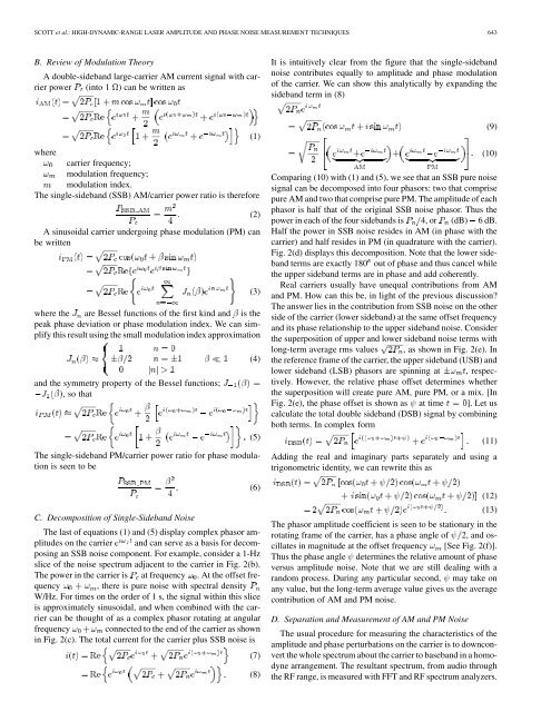
B. Review of Modulation Theory<br />
A double-sideb<strong>and</strong> large-carrier AM current signal with carrier<br />
power (into 1 ) can be written as<br />
It is intuitively clear from the figure that the single-sideb<strong>and</strong><br />
noise contributes equally to amplitude <strong>and</strong> phase modulation<br />
of the carrier. We can show this analytically by exp<strong>and</strong>ing the<br />
sideb<strong>and</strong> term in (8)<br />
(1)<br />
where<br />
carrier frequency;<br />
modulation frequency;<br />
modulation index.<br />
The single-sideb<strong>and</strong> (SSB) AM/carrier power ratio is therefore<br />
A sinusoidal carrier undergoing phase modulation (PM) can<br />
be written<br />
where the are Bessel functions of the first kind <strong>and</strong> is the<br />
peak phase deviation or phase modulation index. We can simplify<br />
this result using the small modulation index approximation<br />
<strong>and</strong> the symmetry property of the Bessel functions;<br />
, so that<br />
The single-sideb<strong>and</strong> PM/carrier power ratio for phase modulation<br />
is seen to be<br />
C. Decomposition of Single-Sideb<strong>and</strong> <strong>Noise</strong><br />
The last of equations (1) <strong>and</strong> (5) display complex phasor amplitudes<br />
on the carrier <strong>and</strong> can serve as a basis for decomposing<br />
an SSB noise component. For example, consider a 1-Hz<br />
slice of the noise spectrum adjacent to the carrier in Fig. 2(b).<br />
The power in the carrier is at frequency . At the offset frequency<br />
, there is pure noise with spectral density<br />
W/Hz. For times on the order of 1 s, the signal within this slice<br />
is approximately sinusoidal, <strong>and</strong> when combined with the carrier<br />
can be thought of as a complex phasor rotating at angular<br />
frequency connected to the end of the carrier as shown<br />
in Fig. 2(c). The total current for the carrier plus SSB noise is<br />
(2)<br />
(3)<br />
(4)<br />
(5)<br />
(6)<br />
(7)<br />
(8)<br />
(9)<br />
(10)<br />
Comparing (10) with (1) <strong>and</strong> (5), we see that an SSB pure noise<br />
signal can be decomposed into four phasors: two that comprise<br />
pure AM <strong>and</strong> two that comprise pure PM. The amplitude of each<br />
phasor is half that of the original SSB noise phasor. Thus the<br />
power in each of the four sideb<strong>and</strong>s is 4, or (dB) 6 dB.<br />
Half the power in SSB noise resides in AM (in phase with the<br />
carrier) <strong>and</strong> half resides in PM (in quadrature with the carrier).<br />
Fig. 2(d) displays this decomposition. Note that the lower sideb<strong>and</strong><br />
terms are exactly 180 out of phase <strong>and</strong> thus cancel while<br />
the upper sideb<strong>and</strong> terms are in phase <strong>and</strong> add coherently.<br />
Real carriers usually have unequal contributions from AM<br />
<strong>and</strong> PM. How can this be, in light of the previous discussion?<br />
The answer lies in the contribution from SSB noise on the other<br />
side of the carrier (lower sideb<strong>and</strong>) at the same offset frequency<br />
<strong>and</strong> its phase relationship to the upper sideb<strong>and</strong> noise. Consider<br />
the superposition of upper <strong>and</strong> lower sideb<strong>and</strong> noise terms with<br />
long-term average rms values , as shown in Fig. 2(e). In<br />
the reference frame of the carrier, the upper sideb<strong>and</strong> (USB) <strong>and</strong><br />
lower sideb<strong>and</strong> (LSB) phasors are spinning at , respectively.<br />
However, the relative phase offset determines whether<br />
the superposition will create pure AM, pure PM, or a mix. [In<br />
Fig. 2(e), the phase offset is shown as at time ]. Let us<br />
calculate the total double sideb<strong>and</strong> (DSB) signal by combining<br />
both terms. In complex form<br />
(11)<br />
Adding the real <strong>and</strong> imaginary parts separately <strong>and</strong> using a<br />
trigonometric identity, we can rewrite this as<br />
(12)<br />
(13)<br />
The phasor amplitude coefficient is seen to be stationary in the<br />
rotating frame of the carrier, has a phase angle of 2, <strong>and</strong> oscillates<br />
in magnitude at the offset frequency [See Fig. 2(f)].<br />
Thus the phase angle determines the relative amount of phase<br />
versus amplitude noise. Note that we are still dealing with a<br />
r<strong>and</strong>om process. During any particular second, may take on<br />
any value, but the long-term average value gives us the average<br />
contribution of AM <strong>and</strong> PM noise.<br />
D. Separation <strong>and</strong> Measurement of AM <strong>and</strong> PM <strong>Noise</strong><br />
The usual procedure for measuring the characteristics of the<br />
amplitude <strong>and</strong> phase perturbations on the carrier is to downconvert<br />
the whole spectrum about the carrier to baseb<strong>and</strong> in a homodyne<br />
arrangement. The resultant spectrum, from audio through<br />
the RF range, is measured with FFT <strong>and</strong> RF spectrum analyzers.