DH100ACDCLPX Air Duct Smoke Detector with Extended Air Speed ...
DH100ACDCLPX Air Duct Smoke Detector with Extended Air Speed ...
DH100ACDCLPX Air Duct Smoke Detector with Extended Air Speed ...

Create successful ePaper yourself
Turn your PDF publications into a flip-book with our unique Google optimized e-Paper software.
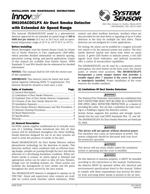
INSTALLATION AND MAINTENANCE INSTRUCTIONS<br />
<strong>DH100ACDCLPX</strong> <strong>Air</strong> <strong>Duct</strong> <strong>Smoke</strong> <strong>Detector</strong><br />
<strong>with</strong> <strong>Extended</strong> <strong>Air</strong> <strong>Speed</strong> Range<br />
3825 Ohio Avenue, St. Charles, Illinois 60174<br />
1-800-SENSOR2, FAX: 630-377-6495<br />
The Innovair <strong>DH100ACDCLPX</strong> model is a photoelectric<br />
detector approved for an extended air speed range of 100 to<br />
4000 feet per minute (0.5 m/s to 20.3 m/s) and an operational<br />
temperature range of 32°F to 131°F (0°C to 55°C).<br />
Before Installing<br />
Please thoroughly read the System Sensor Guide for Proper<br />
Use of <strong>Smoke</strong> <strong>Detector</strong>s in <strong>Duct</strong> Applications (A05-1004),<br />
which provides detailed information on detector spacing,<br />
placement, zoning, wiring, and special applications. Copies<br />
of this manual are available from System Sensor. NFPA<br />
Standards 72 and 90A should also be referenced for detailed<br />
information.<br />
NOTICE: This manual shall be left <strong>with</strong> the owner/user<br />
of this equipment.<br />
IMPORTANT: This detector must be tested and maintained<br />
regularly following NFPA 72 requirements. The<br />
detector should be cleaned at least once a year.<br />
Table of Contents<br />
Page<br />
[1] General Description...................................................... 1<br />
[2] Limitations of <strong>Duct</strong> <strong>Smoke</strong> <strong>Detector</strong>s..............................1<br />
[3] Exploded View of <strong>Duct</strong> <strong>Smoke</strong> <strong>Detector</strong> Components .....2<br />
[4] Contents of the <strong>Duct</strong> <strong>Smoke</strong> <strong>Detector</strong> Kit .......................2<br />
[5] Installation Sequence ....................................................2<br />
[6] <strong>Duct</strong> <strong>Smoke</strong> <strong>Detector</strong> Maintenance and Test Procedures..5<br />
[7] <strong>Detector</strong> Cleaning Procedures ........................................7<br />
[8] Board Replacement .......................................................8<br />
[9] Specifications................................................................8<br />
Warranty............................................................................8<br />
[1] General Description<br />
An HVAC system supplies conditioned air to virtually every<br />
area of a building. <strong>Smoke</strong> introduced into this air duct<br />
system will be distributed throughout the entire building.<br />
<strong>Smoke</strong> detectors designed for use in air duct systems are<br />
used to sense the presence of smoke in the duct.<br />
Model <strong>DH100ACDCLPX</strong> <strong>Air</strong> <strong>Duct</strong> <strong>Smoke</strong> <strong>Detector</strong> utilizes<br />
photoelectric technology for the detection of smoke. This<br />
detection method, when combined <strong>with</strong> an efficient housing<br />
design, samples air passing through the duct and allows<br />
detection of a developing hazardous condition. When sufficient<br />
smoke is sensed, an alarm signal is initiated and<br />
appropriate action can be taken to shut off fans, blowers,<br />
change over air handling systems, etc. These actions can<br />
facilitate the management of toxic smoke and fire gases<br />
throughout the areas served by the duct system.<br />
The <strong>DH100ACDCLPX</strong> detector is designed to operate on 24<br />
VDC/VAC. Alarm and supervisory relay contacts are available<br />
for control panel interface (alarm initiation), HVAC<br />
control, and other auxiliary functions. Auxiliary relays are<br />
also provided for fan shut down or signaling of up to 9 other<br />
detectors in the loop for multiple fan shut down. These<br />
detectors are not designed for 2-wire applications.<br />
For testing, the alarm can be enabled by a magnet activated<br />
test switch or by the optional remote test station. The duct<br />
smoke detector latches into alarm state when an alarm<br />
occurs. A green LED flashes to indicate power, a red LED<br />
signals local alarm indication, and optional accessories<br />
offer a variety of annunciation capabilities.<br />
The <strong>DH100ACDCLPX</strong> can be reset by a momentary power<br />
interruption, the reset button on the front cover, the control<br />
panel, or remote reset accessory. The <strong>DH100ACDCLPX</strong><br />
incorporates a cover tamper feature that provides a<br />
trouble signal after 7 minutes if the cover is removed<br />
or improperly installed. Proper installation of the cover<br />
removes the trouble condition.<br />
[2] Limitations Of <strong>Duct</strong> <strong>Smoke</strong> <strong>Detector</strong>s<br />
WARNING<br />
The National Fire Protection Association has established that<br />
DUCT DETECTORS MUST NOT BE USED AS A SUBSTITUTE<br />
FOR OPEN AREA DETECTOR PROTECTION as a means of<br />
providing life safety. Nor are they a substitute for early warning<br />
in a building’s regular fire detection system.<br />
System Sensor supports this position and strongly recommends<br />
that the user read NFPA Standards 90A, 72, and 101.<br />
The <strong>DH100ACDCLPX</strong> <strong>Air</strong> <strong>Duct</strong> <strong>Smoke</strong> <strong>Detector</strong>s are listed per<br />
UL 268A.<br />
WARNING<br />
This device will not operate <strong>with</strong>out electrical power.<br />
Fire situations may cause an interruption of power. The<br />
system safeguards should be discussed <strong>with</strong> your local<br />
fire protection specialist.<br />
WARNING<br />
This device will not sense smoke unless the ventilation<br />
system is operating and the cover is installed.<br />
WARNING<br />
For this detector to function properly, it MUST be installed<br />
according to the instructions in this manual. Furthermore,<br />
the detector MUST be operated <strong>with</strong>in ALL electrical and<br />
environmental specifications listed in this manual. Failure<br />
to comply <strong>with</strong> these requirements may prevent the detector<br />
from activating when smoke is present in the air duct.<br />
D200-33-00 1 I56-1944-07<br />
38M3201
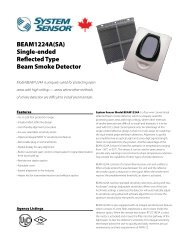
[3] Figure 1. Exploded View Of <strong>Duct</strong> <strong>Smoke</strong> <strong>Detector</strong> Components:<br />
DETECTOR<br />
COVER<br />
DETECTOR BOARD<br />
COVER MOUNTING<br />
SCREWS<br />
POWER BOARD<br />
TERMINAL STRIP<br />
METAL<br />
SAMPLING TUBE<br />
DETECTOR<br />
HOUSING<br />
CONDUIT HOLES<br />
SAMPLING TUBE<br />
FILTERS<br />
[4] Contents Of The <strong>Duct</strong> <strong>Smoke</strong> <strong>Detector</strong> Kit<br />
1. Complete housing base and cover assembly<br />
2. Pre-installed wiring harness<br />
3. Two sampling tube filters (installed)<br />
4. One test magnet<br />
5. One sampling tube end cap<br />
NOTE: Sampling tubes must be ordered to complete the<br />
installation. They must be the correct length for<br />
the width of the duct where they will be installed.<br />
Refer to OEM supplier for correct part number.<br />
[5] Installation Sequence<br />
[5.1] Verify <strong>Duct</strong> <strong>Air</strong> Flow Direction And Velocity<br />
Model <strong>DH100ACDCLPX</strong> detectors are designed to be used<br />
in air handling systems having air velocities of 100 to 4000<br />
feet per minute. Be sure to check engineering specifications<br />
to ensure that the air velocity in the duct falls <strong>with</strong>in these<br />
limits. If necessary, use a velocity meter (anemometer) to<br />
check the air velocity in the duct.<br />
[5.2] Select Mounting Location<br />
The <strong>DH100ACDCLPX</strong> is intended for mounting on ductwork<br />
and/or brackets which have been pre-drilled <strong>with</strong><br />
appropriate mounting holes. While other applications are<br />
possible, they are not covered <strong>with</strong>in this manual.<br />
[5.3] Sampling Tube Installation<br />
Sampling tubes are identified by a series of air inlet holes<br />
along the tube. The correct length tube must be ordered<br />
and installed for each application. See Table 1 for a list of<br />
tubes which are compatible <strong>with</strong> this product. For optimal<br />
performance, it is recommended that the sampling tube<br />
extend at least 2 ⁄3 of the way across the duct width.<br />
Table 1. Sampling Tube Lengths<br />
Approximate Length Part Number to Order Replaces<br />
12 inches STX-10 ST-1<br />
18 inches STX-16 ST-1.5<br />
36 inches STX-34 ST-3<br />
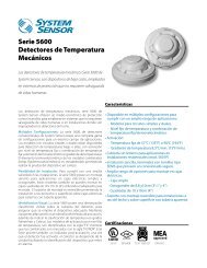
The sampling tube must always be installed <strong>with</strong> the air<br />
inlet holes facing into the air flow. Figure 2 shows the various<br />
combinations of tube mounting configurations <strong>with</strong><br />
respect to air flow. Mounting the detector in a vertical orientation<br />
is acceptable, provided that the air flows directly<br />
into the sampling tube holes, as indicated in Figure 3.<br />
NOTE: The sampling tube end cap is critical to the proper<br />
operation of the duct smoke detector. The end cap<br />
is needed to create the proper air flow to the sensor<br />
of the duct smoke detector.<br />
Figure 2. Tube mounting configurations <strong>with</strong> varying<br />
air flow direction:<br />
AIR FLOW<br />
DIRECTION<br />
DETECTOR<br />
HOUSING<br />
AIR FLOW<br />
DIRECTION<br />
DETECTOR<br />
HOUSING<br />
SAMPLING<br />
TUBE<br />
EXHAUST<br />
TUBE<br />
FOAM<br />
GASKETS<br />
DOTS INDICATE POSITION OF<br />
SAMPLING TUBE HOLES<br />
A. B.<br />
EXHAUST<br />
TUBE<br />
SAMPLING<br />
TUBE<br />
HORIZONTAL MOUNTING OF HOUSING<br />
EXHAUST<br />
TUBE<br />
SAMPLING<br />
TUBE<br />
C. D.<br />
VERTICAL MOUNTING OF HOUSING<br />
H0174-00<br />
AIR FLOW<br />
DIRECTION<br />
DETECTOR<br />
HOUSING<br />
DETECTOR<br />
HOUSING<br />
AIR FLOW<br />
DIRECTION<br />
H0109-01<br />
D200-33-00 2 I56-1944-07
Figure 3. <strong>Air</strong> duct detector sampling tube:<br />
Figure 5. Sampling tube filter installation:<br />
AIR HOLES<br />
STOP SCREW<br />
SAMPLING<br />
TUBE<br />
END<br />
CAP<br />
MOUNTING HOLES<br />
AT 90° INCREMENTS<br />
AIR FLOW DIRECTION<br />
H0171-00<br />
Sampling tubes for this product are designed to be inserted<br />
from the outside, <strong>with</strong>out removing the cover, prior to<br />
installing the detector into its application.<br />
1. Install the end cap into the end of the tube farthest from<br />
the stop screw.<br />
2. Slide the tube into whichever bushing will be used for the<br />
air inlet, and push it all the way to the stop. The end of<br />
the tube <strong>with</strong> the four small holes goes into the bushing.<br />
3. Rotate the tube so that the holes face into the airflow,<br />
then adjust until the hole in the bushing lines up <strong>with</strong><br />
one of the four mounting holes in the tube.<br />
4. Secure the tube by inserting a #6 × 3 ⁄4˝ sheet metal<br />
screw through the hole in the bushing and the mounting<br />
hole in the tube. See Figure 4.<br />
Figure 4. Sampling tube connected to duct smoke<br />
detector:<br />
A78-2752-00<br />
[5.4] Install the <strong>Detector</strong> Housing<br />
Feed the sampling tube and the exhaust port through the predrilled<br />
holes in the mounting location, then use two screws<br />
to secure the housing to the mounting surface.<br />
Caution: Do not overtighten the screws.<br />
[5.5] <strong>Air</strong> Filters<br />
<strong>Air</strong> filters must be installed in both the inlet and exhaust<br />
openings inside the detector. These filters are initially<br />
installed at the factory. To remove for cleaning. loosen the<br />
holding tab and pull the filter out. Replace the filters by<br />
pushing them into the sampling and exhaust tube holes, as<br />
shown in Figure 5, then replacing the holding tabs.<br />
CAUTION<br />
H0131-00<br />
Filters require periodic cleaning or replacement, depending<br />
on the amount of dust and dirt accumulated. Visually<br />
inspect the filters at least quarterly; inspect them more<br />
often if the dust accumulation warrants it. See Section [6]<br />
for more information. Replacement filters can be ordered<br />
from System Sensor, 3825 Ohio Ave., St. Charles, IL 60174.<br />
(Exhaust tube/intake tube filter P/N F36-09-11)<br />
[5.6] Field Wiring<br />
Installation Guidelines<br />
All wiring must be installed in compliance <strong>with</strong> the<br />
National Electrical Code and the local codes having jurisdiction.<br />
Proper wire gauges should be used. The conductors<br />
used to connect smoke detectors to control panels and<br />
accessory devices should be color-coded to prevent wiring<br />
mistakes. Improper connections can prevent a system from<br />
responding properly in the event of a fire.<br />
For signal wiring, (the wiring between interconnected<br />
detectors or from detectors to auxiliary devices), it is<br />
usually recommended that single conductor wire be no<br />
smaller than 18 gauge. The duct smoke detector terminals<br />
accommodate wire sizes up to 12 gauge.<br />
<strong>Smoke</strong> detectors and alarm system control panels have<br />
specifications for allowable loop resistance. Consult the<br />
control panel manufacturer’s specifications for the total<br />
loop resistance allowed for the particular model control<br />
panel being used before wiring the detector loop.<br />
Wiring Instructions<br />
The <strong>DH100ACDCLPX</strong> detectors are designed for easy wiring.<br />
The housing provides a terminal strip <strong>with</strong> clamping<br />
plates. Wiring connections are made by stripping about 3 ⁄8″<br />
of insulation from the end of the wire, sliding the bare end<br />
under the plate, and tightening the clamping plate screw.<br />
[5.7] Perform <strong>Detector</strong> Check<br />
1. Perform STANDBY AND TROUBLE TEST per Section<br />
[6.2.1].<br />
2. Perform MAGNET TEST per Section [6.2.2.1]. The<br />
RTS451 test of Section [6.2.2.2] may substitute for this<br />
requirement.<br />
3. Perform AIR FLOW TEST per Section [6.1.1].<br />
4. Perform SMOKE RESPONSE TEST per Section [6.1.2].<br />
5. Perform SENSITIVITY TEST per Section [6.2.3].<br />
D200-33-00 3 I56-1944-07
[5.8] Install The Cover<br />
Install the cover using the six screws that are captured in<br />
the housing cover. Be certain filters are installed as specified<br />
in Section [5.5]. Make sure that the cover fits into the<br />
base groove and that all gaskets are in their proper positions.<br />
Tighten the six screws.<br />
[6] <strong>Duct</strong> <strong>Smoke</strong> <strong>Detector</strong> Maintenance And Test<br />
Procedures<br />
Test and maintain duct smoke detectors as recommended<br />
in NFPA 72. The tests contained in this manual were<br />
devised to assist maintenance personnel in verification of<br />
proper detector operation.<br />
Before conducting these tests, notify the proper authorities<br />
that the smoke detection system will be temporarily out of<br />
service. Disable the zone or system under test to prevent<br />
unwanted alarms.<br />
[6.1] <strong>Smoke</strong> Entry Tests<br />
[6.1.1] <strong>Air</strong> Flow<br />
The <strong>DH100ACDCLPX</strong> is designed to operate over an extended<br />
air speed range of 100 to 4000 FPM. To verify sufficient sampling<br />
of ducted air, turn the air handler on and use a manometer<br />
to measure the differential pressure between the two<br />
sampling tubes. The differential pressure should measure<br />
at least 0.0015 inches of water and no more than 1.2 inches<br />
of water. Because most commercially available manometers<br />
cannot accurately measure very low pressure differentials,<br />
applications <strong>with</strong> less than 500 FPM of duct air speed may<br />
require one of the following: 1) the use of a current-sourcing<br />
pressure transmitter (Dwyer Series 607) per Section 6.1.4 or;<br />
2) the use of aerosol smoke per section 6.1.2.<br />
[6.1.2] <strong>Air</strong> Flow Test using Aerosol <strong>Smoke</strong><br />
This test is intended for low-flow systems (100-500FPM). If<br />
the air speed is greater than 500 FPM, use a conventional<br />
manometer to measure differential pressure between the<br />
sampling tubes as described in 6.1.1.<br />
carrying smoke away from the detector head, then blow<br />
smoke such as cigarette, cotton wick, or punk directly at<br />
the head to cause an alarm. REMEMBER TO REMOVE THE<br />
PLUGS AFTER THIS TEST, OR THE DETECTOR WILL NOT<br />
FUNCTION PROPERLY.<br />
[6.1.4] <strong>Air</strong> Flow Test using Dwyer Series 607<br />
Differential Pressure Transmitter<br />
Verify the air speed of the duct using an anemometer. <strong>Air</strong><br />
speed must be at least 100 FPM. Wire the Dwyer transmitter<br />
as shown in Figure 6. Connect the leads of the meter<br />
to either side of the 1000Ω resistor. Allow unit to warm up<br />
for 15 seconds. With both HIGH and LOW pressure ports<br />
open to ambient air, measure and record the voltage drop<br />
acrossthe 1000Ω resistor (measurement 1), 4.00 volts is<br />
typical. Using flexible tubing and rubber stoppers, connect<br />
the HIGH side of the transmitter to the inlet sampling tube<br />
of the duct smoke detector housing, and the LOW side of<br />
the transmitter to the exhaust sampling tube of the duct<br />
smoke detector housing. Measure and record the voltage<br />
drop across the 1000Ω resistor (measurement 2). Subtract<br />
the voltage recorded in measurement 1 from the voltage<br />
recorded in measurement 2. If the difference is greater than<br />
0.15 volts, there is enough air flow through the duct smoke<br />
detector for proper operation.<br />
Figure 6. Procedure for verifying air flow:<br />
HIGH<br />
DIFFERENTIAL<br />
PRESSURE<br />
TRANSMITTER<br />
MODEL #607-01<br />
LOW<br />
1000 OHM 5% 1 WATT RESISTOR<br />
TO SAMPLING TUBE<br />
TO EXHAUST TUBE<br />
9 VOLT<br />
BATTERY<br />
15 TO 36VDC<br />
SUPPLY<br />
9 VOLT<br />
BATTERY<br />
9 VOLT<br />
BATTERY<br />
Drill a 1 ⁄4″ hole 3 feet upstream from the duct smoke detector.<br />
With the air handler on, measure the air velocity <strong>with</strong><br />
an anemometer. <strong>Air</strong> speed must be at least 100 FPM. Spray<br />
aerosol smoke* into the duct through the 1 ⁄4″ hole for five<br />
seconds. Wait two minutes for the duct smoke detector to<br />
alarm. If the duct smoke detector alarms, air is flowing<br />
through the detector. Remove the duct smoke detector cover<br />
and blow out the residual aerosol smoke from the chamber<br />
and reset the duct smoke detector. Use duct tape to seal the<br />
aerosol smoke entry hole.<br />
*Aerosol smoke can be purchased from Home Safeguard Industries,<br />
Malibu, CA. Phone: 310/457-5813.<br />
VOLT METER<br />
FLUKE MODEL 87<br />
OR EQUIVALENT<br />
H0163-01<br />
[6.1.5] Filter Replacement<br />
The filters do not substantially affect smoke performance<br />
even when up to 90% of the filter is clogged. Quarterly<br />
visual inspection usually suffices to determine whether the<br />
filters should be replaced because only a high percentage<br />
of contamination affects performance. If further testing is<br />
required, compare differential pressure readings <strong>with</strong> and<br />
<strong>with</strong>out the filters installed. If the difference exceeds 10%<br />
replace the filters. In no case should the pressure differential<br />
fall below 0.0015 inches of water.<br />
[6.1.3] <strong>Smoke</strong> Entry Test<br />
To determine if smoke is capable of entering the sensing<br />
chamber, visually identify any obstructions. Plug the<br />
[6.2] Standby, Alarm and Sensitivity Tests<br />
The cover must be removed to perform these tests. The use<br />
exhaust and inlet tube holes to prevent ducted air from<br />
of a remote accessory for visible indication of power and<br />
alarm is recommended.<br />
D200-33-00 4 I56-1944-07
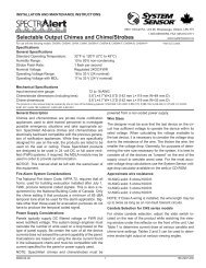
Figure 7. System wiring diagram for 4-wire duct smoke detectors:<br />
CAUTION<br />
Do not loop wire under terminals when wiring detectors. Break wire runs to provide system supervision of connections.<br />
POWER INPUTS ACCEPT<br />
24 VDC, 24 VAC 50-60 HZ,<br />
CONNECT POWER SOURCE<br />
TO APPROPRIATE TERMINALS<br />
OF EACH DETECTOR.<br />
AVAILABLE POWER INPUTS<br />
9 10<br />
24V<br />
AVAILABLE POWER INPUTS<br />
9 10<br />
24V<br />
CONNECT POWER SOURCE<br />
TO APPROPRIATE TERMINALS<br />
OF EACH DETECTOR. SEE<br />
SPECIFICATIONS FOR<br />
ADDITIONAL POWER SUPPLY<br />
INFORMATION.<br />
AUX. CONTACT RATINGS<br />
10A @ 30 VDC RESISTIVE<br />
100mA MINIMUM @ 5 VDC<br />
1/4 HP @ 240 VAC<br />
1/8 HP @ 120 VAC<br />
NOT INTENDED FOR<br />
CONNECTION TO CONTROL<br />
PANELS.<br />
TROUBLE CONTACT RATING<br />
2.0 A @ 30 VDC resistive<br />
2.0 A @ 125 VAC resistive<br />
N.C.<br />
ALARM AUXILIARY CONTACTS<br />
FOR FAN SHUTDOWN, ETC.<br />
16 6 17 7 18 8<br />
C.<br />
N.O.<br />
N.O.<br />
ALARM AUXILIARY CONTACTS SHOWN IN<br />
STANDBY. CONTACTS TRANSFER DURING<br />
ALARM AS INDICATED BY THE ARROWS.<br />
C.<br />
SUPERVISORY TROUBLE CONTACTS<br />
N.C.<br />
N.C.<br />
ALARM AUXILIARY CONTACTS<br />
FOR FAN SHUTDOWN, ETC.<br />
16 6 17 7 18 8<br />
C.<br />
N.O.<br />
N.O.<br />
ALARM AUXILIARY CONTACTS SHOWN IN<br />
STANDBY. CONTACTS TRANSFER DURING<br />
ALARM AS INDICATED BY THE ARROWS.<br />
C.<br />
SUPERVISORY TROUBLE CONTACTS<br />
14 3 14<br />
3<br />
N.C.<br />
FOR WIRING OF AUXILIARY<br />
DEVICES, REFER TO<br />
MANUFACTURER'S<br />
INSTALLATION INSTRUCTIONS<br />
OR CONTACT MANUFACTURER.<br />
NOTE: THE SUPERVISORY RELAY NOW<br />
PROVIDES A "FORM C" CONTACT FOR<br />
CUSTOMIZED APPLICATIONS.<br />
FOR STANDARD APPLICATIONS, ONLY<br />
THE "NO" CONTACT IS USED<br />
TROUBLE CONTACTS CLOSED IN ALARM AND STANDBY.<br />
CONTACTS OPEN WHILE DETECTOR PCB OR POWER IS<br />
REMOVED OR WHEN TAMPER FEATURE TIMES OUT. OPEN<br />
CONTACTS SIGNAL TROUBLE CONDITION TO PANEL.<br />
TROUBLE CONTACTS CLOSED IN ALARM AND STANDBY.<br />
CONTACTS OPEN WHILE DETECTOR PCB OR POWER IS<br />
REMOVED OR WHEN TAMPER FEATURE TIMES OUT. OPEN<br />
CONTACTS SIGNAL TROUBLE CONDITION TO PANEL.<br />
+<br />
5<br />
5<br />
ALARM<br />
INITIATION<br />
LOOP<br />
ALARM<br />
INITIATION<br />
CONTACTS<br />
4<br />
CONTACTS SHOWN<br />
OPEN IN STANDBY.<br />
CONTACTS CLOSE<br />
IN ALARM.<br />
ALARM<br />
INITIATION<br />
CONTACTS<br />
4<br />
CONTACTS SHOWN<br />
OPEN IN STANDBY.<br />
CONTACTS CLOSE<br />
IN ALARM.<br />
UL LISTED 4-WIRE<br />
CONTROL PANEL<br />
FIRST DETECTOR IN THE LOOP<br />
<strong>DH100ACDCLPX</strong><br />
LAST DETECTOR IN THE LOOP<br />
<strong>DH100ACDCLPX</strong><br />
EOL RESISTOR<br />
SPECIFIED BY<br />
PANEL MANUFACTURER<br />
H0172-00<br />
Figure 8. Wiring diagram for <strong>DH100ACDCLPX</strong><br />
to APA451:<br />
<br />
<br />
<br />
<br />
<br />
<br />
<br />
<br />
<br />
<br />
<br />
Figure 9. Wiring diagram for <strong>DH100ACDCLPX</strong> to<br />
RTS451/RTS451KEY:<br />
<br />
<br />
<br />
<br />
<br />
<br />
<br />
<br />
<br />
<br />
<br />
<br />
<br />
<br />
<br />
<br />
<br />
<br />
<br />
<br />
<br />
<br />
<br />
<br />
<br />
<br />
<br />
<br />
<br />
<br />
<br />
<br />
<br />
<br />
<br />
A78-2740-00<br />
<br />
<br />
<br />
<br />
<br />
<br />
A78-2741-00<br />
Figure 10. Multiple fan shutdown (interconnect):<br />
1 6<br />
A B C 1 6<br />
A B C<br />
12 16<br />
12 16<br />
OUT TO<br />
10 DETECTORS<br />
MAXIMUM<br />
DETECTOR 1<br />
DETECTOR 2<br />
SYSTEM<br />
SYSTEM<br />
FAN<br />
CONTROL<br />
FAN<br />
CONTROL<br />
CONTROL<br />
POWER OR<br />
CONTROL<br />
POWER OR<br />
THERMOSTAT<br />
THERMOSTAT<br />
H0155-01<br />
1 6<br />
12 16<br />
FAN<br />
CONTROL<br />
A B C<br />
DETECTOR 10<br />
SYSTEM<br />
CONTROL<br />
POWER OR<br />
THERMOSTAT<br />
Important Interconnect Notes<br />
• When using the interconnect feature, all<br />
interconnected units must be powered <strong>with</strong><br />
the same, independent supply.<br />
• Polarity must be maintained throughout<br />
the interconnect wiring. Connect terminal<br />
12 on unit 1 to terminal 12 on unit 2 and so<br />
on. Similarly, connect terminal 1 on unit 1<br />
to terminal 1 on unit 2 and so on.<br />
• Up to 10 units may be interconnected.<br />
D200-33-00 5 I56-1944-07
Figure 11. Wiring diagrams for optional accessories:<br />
<br />
<br />
<br />
<br />
<br />
<br />
<br />
<br />
<br />
<br />
<br />
<br />
<br />
<br />
Figure 13. Testing detector alarm:<br />
<br />
<br />
<br />
<br />
<br />
<br />
<br />
<br />
A78-2742-00<br />
Figure 12. Wiring diagram for <strong>DH100ACDCLPX</strong> to<br />
SSK451:<br />
SSK451<br />
COMMON 3<br />
TEMPORAL SELECT 2<br />
ALARM SIGNAL 1<br />
SUPERVISORY SIGNAL 4<br />
RESET 7<br />
TEST 8<br />
POWER (–) 6<br />
POWER (+) 5<br />
FIELD INSTALLED<br />
JUMPER FOR<br />
TEMPORAL PATTERN<br />
15 ALARM SIGNAL<br />
3<br />
NO<br />
14<br />
<strong>DH100ACDCLPX</strong><br />
2 RESET<br />
11 TEST<br />
SUPERVISORY<br />
CONTACT<br />
20 AUX. POWER (–)<br />
19 AUX. POWER (+)<br />
H0130-00<br />
[6.2.1] Standby And Trouble<br />
Standby — Look for the presence of the flashing green LED. The<br />
LED should flash approximately every 10 seconds.<br />
Trouble — If the detector LED does not flash, then the detector<br />
lacks power (check wiring, panel, or power<br />
supply), the detector board is missing (replace),<br />
the cover has been missing or not secured properly<br />
for more than 7 minutes (secure cover properly),<br />
or the unit is defective (return for repair).<br />
Test — The trouble condition can be caused intentionally<br />
to verify correct operation of the system. Remove<br />
the detector board to cause a trouble condition<br />
locally and at the system control panel.<br />
Cover<br />
Tamper — If the cover is removed or not properly secured<br />
for a period longer than 7 minutes, a trouble<br />
signal is generated to indicate the cover is missing.<br />
[6.2.2] Alarm Tests<br />
[6.2.2.1] M02-04-00 Magnet Test<br />
1. Place the painted surface of the magnet onto the TEST<br />
locator on the bottom of the housing (Figure 13).<br />
2. The red alarm LED on the detector should latch on, as<br />
should any accessories (i.e. RA400Z, RTS451). Verify<br />
system control panel alarm status and control panel<br />
execution of all intended auxiliary functions (i.e. fan<br />
shutdown, damper control, etc.).<br />
3. The detector must be reset by system control panel, front<br />
cover reset button, or remote accessory.<br />
[6.2.2.2] RTS451/RTS451KEY Remote Test Station<br />
The RTS451/RTS451KEY Remote Test Station facilitates<br />
test of the alarm capability of the duct smoke detector<br />
as indicated in the RTS451/RTS451KEY manual. The<br />
<strong>DH100ACDCLPX</strong> duct smoke detector can be reset by the<br />
RTS451/RTS451KEY. If a system control panel is used, the<br />
panel itself may also require testing.<br />
FIELD INSTALLED<br />
JUMPER<br />
A78-2743-00<br />
To install the RTS451/RTS451KEY, connect the device as<br />
shown in Figure 9; wire runs must be limited to 25 ohms<br />
or less per interconnecting wire.<br />
Please note that the magnetic coil supplied <strong>with</strong> the<br />
RTS451 and RTS451KEY is not required when these<br />
accessories are used <strong>with</strong> the DH100 Series detectors.<br />
The functionality of the magnetic coil has been designed<br />
into the circuitry of the new Innovair duct smoke detectors.<br />
[6.2.2.3] SSK451 Multi-Signaling Accessory<br />
The System Sensor SSK451 Multi-Signaling accessory combines<br />
a sounder feature <strong>with</strong> a key activated test and reset<br />
function. Green, amber and red LEDs provide a visual indication<br />
of power, trouble, and alarm respectively. An optional<br />
strobe (PS24LO) <strong>with</strong> a smoke lens can be added to conform<br />
to the codes of certain jurisdictions. To install the SSK451,<br />
connect the device as shown in figure 13.<br />
[6.2.3] Sensitivity Tests<br />
[6.2.3.1] MOD400 or MOD400R Test<br />
After verification of alarm capability, use the MOD400R test<br />
module <strong>with</strong> a voltmeter to check detector sensitivity as<br />
indicated in the test module’s manual. The housing cover<br />
must be removed to perform this test.<br />
If test module readings indicate that the detector head is<br />
outside of the acceptable range that is printed on the label<br />
of the detector, the detector chamber requires cleaning per<br />
Section [7] of this manual.<br />
[7] <strong>Detector</strong> Cleaning Procedures<br />
Notify the proper authorities that the smoke detector system<br />
is undergoing maintenance, and that the system will<br />
temporarily be out of service. Disable the zone or system<br />
undergoing maintenance to prevent unwanted alarms and<br />
possible dispatch of the fire department.<br />
[7.1] <strong>Air</strong> Filters<br />
1. Turn off power to the system.<br />
2. Remove and inspect sampling tube filters.<br />
3. If filters are heavily coated <strong>with</strong> dirt, replace them <strong>with</strong><br />
new filters. If they are not heavily coated, use a vacuum<br />
cleaner or compressed air nozzle to remove dust, then<br />
reinstall the filters.<br />
D200-33-00 6 I56-1944-07
[7.2] Photo <strong>Detector</strong> Board<br />
1. Remove the screen by gently grasping on each side and<br />
pulling straight off.<br />
2. Lift the photo chamber in the same fashion. Vacuum<br />
the screen and cover. Use clean, compressed air to<br />
loosen and blow out any remaining debris. Replacement<br />
screens (S08-39-01) are available.<br />
3. Vacuum photo chamber, then use clean compressed air<br />
to blow area clean.<br />
4. Replace the chamber by pressing it onto the base.<br />
Press the screen into place. It should fit tightly on the<br />
chamber.<br />
[8.2] Power Board replacement (Part No. A5064)<br />
1. Disconnect wiring from the terminal block.<br />
2. Remove the two power board mounting screws.<br />
3. Pull gently on the board to remove it.<br />
4. To replace the board, align the board mounting features,<br />
holes, and the interconnect terminals. Push the<br />
board into place.<br />
5. Secure board <strong>with</strong> the two mounting screws.<br />
6. Re-connect wiring to terminal block.<br />
[8.0] Board Replacement<br />
[8.1] <strong>Detector</strong> Board Replacement (Part No. A5190)<br />
1. Remove the two detector board mounting screws.<br />
2. Pull gently on the board to remove it.<br />
3. To replace the board, align the board mounting features,<br />
holes, and the interconnect terminals. Push the<br />
board into place.<br />
4. Secure board <strong>with</strong> the two mounting screws.<br />
[9] Model <strong>DH100ACDCLPX</strong> <strong>Air</strong> <strong>Duct</strong> <strong>Smoke</strong> <strong>Detector</strong> Specifications<br />
Operating temperature: +32° to +131° F (0° to +55° C)<br />
Storage temperature: –22° to +158°F (–30° to +70°C)<br />
Humidity:<br />
10% to 93% R.H. noncondensing<br />
<strong>Air</strong> Velocity:<br />
100 to 4000 ft./min.<br />
(0.5 to 20.3 m/sec.)<br />
Dimensions:<br />
14.38″ L x 5.5″ W x 2.75″ D<br />
(37cm L x 14cm W x 7cm D)<br />
Weight:<br />
3.75 pounds (1.7 kg)<br />
Electrical Specifications<br />
Power supply voltage: 20-29 VDC; 24 VAC 50-60-Hz<br />
Input capacitance:<br />
270 µF max.<br />
Reset voltage:<br />
3.0 VDC min.; 2.0 VAC min.<br />
Reset time (<strong>with</strong> RTS451): .03 to 0.3 sec.<br />
Reset time (by power down): 0.6 sec. max.<br />
Power up time:<br />
34 sec. max.<br />
Alarm response time: 2 to 17 sec.<br />
Sensitivity Test:<br />
See detector label<br />
Please refer to page 11 & 12 for Limitations of Fire Alarm Systems<br />
System Sensor warrants its enclosed air duct smoke detector to be free from defects<br />
in materials and workmanship under normal use and service for a period of three<br />
years from date of manufacture. System Sensor makes no other express warranty<br />
for this air duct smoke detector. No agent, representative, dealer, or employee of<br />
the Company has the authority to increase or alter the obligations or limitations<br />
of this Warranty. The Company’s obligation of this Warranty shall be limited to<br />
the repair or replacement of any part of the air duct smoke detector which is<br />
found to be defective in materials or workmanship under normal use and service<br />
during the three year period commencing <strong>with</strong> the date of manufacture. After<br />
phoning System Sensor’s toll free number 800-SENSOR2 (736-7672) for a Return<br />
Authorization number, send defective units postage prepaid to: System Sensor,<br />
Three-Year Limited Warranty<br />
Power Supply Voltage 20 - 29 VDC 24 VAC 50 - 60 Hz<br />
CURRENT REQUIREMENTS (USING NO ACCESSORIES)<br />
Max. standby current 15 mA 35 mA RMS<br />
Max. alarm current 70 mA 125 mA RMS<br />
CONTACT RATINGS<br />
Alarm initiation contacts (SPST)<br />
2.0A @ 30 VDC (resistive)<br />
Alarm auxiliary contacts (DPDT) 10A @ 30 VDC<br />
10A @ 250 VAC<br />
1/4 HP @ 240 VAC<br />
1/8 HP @ 120 VAC<br />
Note: Alarm auxiliary contacts must switch 100 mA minimum at 5VDC.<br />
Alarm auxiliary contacts shall not be connected to initiating circuits<br />
of control panels. Use the alarm initiation contact for this purpose.<br />
Trouble contacts (SPDT)<br />
2.0A @ 30 VDC (resistive)<br />
2.0A @ 125 VAC (resistive)<br />
ACCESSORY CURRENT LOADS AT 24 VDC<br />
DEVICE<br />
APA451<br />
PA400<br />
RA400Z<br />
RTS451<br />
RTS451KEY<br />
SSK451<br />
STANDBY<br />
12.5mA Max.<br />
0mA<br />
0mA<br />
0mA<br />
12mA*<br />
5mA Max.<br />
TROUBLE<br />
n/a<br />
n/a<br />
n/a<br />
n/a<br />
n/a<br />
9mA Max.<br />
ALARM<br />
30mA Max.<br />
15mA Max.<br />
10mA Max.<br />
7.5mA Max.<br />
7.5mA Max.<br />
30mA Max.<br />
H0173-00<br />
Returns Department, RA #__________, 3825 Ohio Avenue, St. Charles, IL 60174.<br />
Please include a note describing the malfunction and suspected cause of failure.<br />
The Company shall not be obligated to repair or replace units which are found to<br />
be defective because of damage, unreasonable use, modifications, or alterations<br />
occurring after the date of manufacture. In no case shall the Company be liable for<br />
any consequential or incidental damages for breach of this or any other Warranty,<br />
expressed or implied whatsoever, even if the loss or damage is caused by the<br />
Company’s negligence or fault. Some states do not allow the exclusion or limitation<br />
of incidental or consequential damages, so the above limitation or exclusion may<br />
not apply to you. This Warranty gives you specific legal rights, and you may also<br />
have other rights which vary from state to state.<br />
D200-33-00 7 I56-1944-07
D200-33-00 8 I56-1944-07<br />
© 2003 System Sensor
D200-33-00 9 I56-1944-07<br />
© 2003 System Sensor
D200-33-00 10 I56-1944-07<br />
© 2003 System Sensor
Limitations of Fire Alarm Systems<br />
Manufacturer recommends that smoke and/or heat detectors be located<br />
throughout a protected premise following the recommendations of<br />
the current edition of the National Fire Protection Association Standard<br />
72, National Fire Alarm Code (NFPA 72), manufacturer’s recommendations,<br />
state and local codes, and the recommendations contained in<br />
Guide for the Proper Use of System <strong>Smoke</strong> <strong>Detector</strong>s, which is made<br />
available at no charge to all installing dealers. A study by the Federal<br />
Emergency Management Agency (an agency of the United States government)<br />
indicated that smoke detectors may not go off or give early<br />
warning in as many as 35% of all fires. While fire alarm systems are<br />
designed to provide warning against fire, they do not guarantee warning<br />
or protection against fire. Any alarm system is subject to compromise<br />
or failure to warn for a variety of reasons. For example:<br />
• Particles of combustion or “smoke” from a developing fire may<br />
not reach the sensing chambers of the smoke detector because:<br />
- Barriers such as closed or partially closed doors, walls, or<br />
chimneys may inhibit flow.<br />
- <strong>Smoke</strong> particles may become “cold” and stratify, and may<br />
not reach the ceiling or upper walls where detectors are located.<br />
- <strong>Smoke</strong> particles may be blown away from detectors by air outlets.<br />
- <strong>Smoke</strong> particles may be drawn into air returns before reaching<br />
the detector.<br />
In general, smoke detectors on one level of a structure cannot be<br />
expected to sense fires developing on another level.<br />
• The amount of “smoke” present may be insufficient to alarm<br />
smoke detectors. <strong>Smoke</strong> detectors are designed to alarm at<br />
various levels of smoke density. If such density levels are not<br />
created by a developing fire at the location of detectors, the<br />
detectors will not go into alarm.<br />
• <strong>Smoke</strong> detectors, even when working properly, have sensing<br />
limitations. <strong>Detector</strong>s that have photoelectronic sensing chambers<br />
tend to detect smoldering fires better than flaming fires,<br />
which have little visible smoke. <strong>Detector</strong>s that have ionizingtype<br />
sensing chambers tend to detect fast flaming fires better<br />
than smoldering fires. Because fires develop in different ways<br />
and are often unpredictable in their growth, neither type of<br />
detector is necessarily best and a given type of detector may not<br />
provide adequate warning of a fire.<br />
• <strong>Smoke</strong> detectors are subject to false alarms and nuisance alarms.<br />
For example, a smoke detector located in or near a kitchen may<br />
go into nuisance alarm during normal operation of kitchen appliances.<br />
In addition, dusty or steamy environments may cause a<br />
smoke detector to falsely alarm. If the location of a smoke detector<br />
causes an abundance of false alarms or nuisance alarms, do<br />
not disconnect the smoke detector; call a professional to analyze<br />
the situation and recommend a solution.<br />
• <strong>Smoke</strong> detectors cannot be expected to provide adequate warning<br />
of fires caused by arson, children playing <strong>with</strong> matches<br />
(especially <strong>with</strong>in bedrooms), smoking in bed, violent explosions<br />
(caused by escaping gas, improper storage of flammable<br />
materials, etc.).<br />
• Heat detectors do not sense particles of combustion and are designed<br />
to alarm only when heat on their sensors increase at a<br />
predetermined rate or reaches a predetermined level. Heat detectors<br />
are designed to protect property, not life.<br />
• Warning devices (including horns, sirens, and bells) may not<br />
alert people or wake up sleepers who are located on the other<br />
side of closed or partially open doors. A warning device that<br />
activates on a different floor or level of a dwelling or structure is<br />
less likely to awaken or alert people. Even persons who are<br />
awake may not notice the warning if the alarm is muffled by<br />
noise from a stereo, radio, air conditioner or other appliance, or<br />
by passing traffic. Audible warning devices may not alert the<br />
hearing-impaired (strobes or other devices should be provided to<br />
warn these people). Any warning device may fail to alert people<br />
<strong>with</strong> a disability, deep sleepers, people who have recently used<br />
alcohol or drugs, or people on medication or sleeping pills.<br />
- Please note that:<br />
i) Strobes can, under certain circumstances, cause seizures<br />
in people <strong>with</strong> conditions such as epilepsy.<br />
ii) Studies have shown that certain people, even when they<br />
hear a fire alarm signal, do not respond or comprehend<br />
the meaning of the signal. It is the property owner’s responsibility<br />
to conduct fire drills and other training exercises<br />
to make people aware of fire alarm signals and instruct<br />
on the proper reaction to alarm signals.<br />
iii) In rare instances, the sounding of a warning device can<br />
cause temporary or permanent hearing loss.<br />
• Telephone lines needed to transmit alarm signals from a premises<br />
to a central station may be out of service or temporarily out<br />
of service. For added protection against telephone line failure,<br />
backup radio transmission systems are recommended.<br />
• System components, though designed to last many years, can<br />
fail at any time. As a precautionary measure, it is recommended<br />
that smoke detectors be checked, maintained, and replaced per<br />
manufacturer’s recommendations.<br />
• System components will not work <strong>with</strong>out electrical power. If<br />
system batteries are not serviced or replaced regularly, they may<br />
not provide battery backup when AC power fails.<br />
• Environments <strong>with</strong> high air velocity or that are dusty or dirty<br />
require more frequent maintenance.<br />
• To keep your fire alarm system in excellent working order, ongoing<br />
maintenance is required per the manufacturer’s recommendations<br />
and UL and NFPA standards. At a minimum the<br />
requirements of Chapter 7 of NFPA 72 shall be followed. A maintenance<br />
agreement should be arranged through the local manufacturer’s<br />
representative. Maintenance should be performed<br />
annually by authorized personnel only.<br />
• The most common cause of an alarm system not functioning<br />
when a fire occurs is inadequate maintenance. As such, the<br />
alarm system should be tested weekly to make sure all sensors<br />
and transmitters are working properly.<br />
• Although designed for long life, fire alarm devices including<br />
smoke detectors may fail at any time. It is recommended that<br />
smoke detectors shall be replaced every 10 years.<br />
• Any smoke detector, fire alarm system or any component of that<br />
system which fails shall be repaired or replaced immediately.<br />
In general, fire alarm systems and devices will not work <strong>with</strong>out<br />
power and will not function properly unless they are maintained<br />
and tested regularly.<br />
While installing a fire alarm system may make the owner eligible<br />
for a lower insurance rate, an alarm system is not a substitute for<br />
insurance. Property owners should continue to act prudently in<br />
protecting the premises and the people in the premises and should<br />
properly insure life and property and buy sufficient amounts of<br />
liability insurance to meet their needs.<br />
D200-33-00 11 I56-1944-07<br />
© 2003 System Sensor
Requirements and recommendations<br />
for proper use of fire alarm systems<br />
including smoke detectors and other<br />
fire alarm devices:<br />
Early fire detection is best achieved by the installation and maintenance<br />
of fire detection equipment in all rooms and areas of<br />
the house or building in accordance <strong>with</strong> the requirements and<br />
recommendations of the current edition of the National Fire Protection<br />
Association Standard 72, National Fire Alarm Code (NFPA<br />
72), the manufacturer’s recommendations, State and local codes<br />
and the recommendations contained in Guide for the Proper Use<br />
of System <strong>Smoke</strong> <strong>Detector</strong>s, which is made available at no charge<br />
to all installing dealers. For specific requirements, check <strong>with</strong><br />
the local Authority Having Jurisdiction (ex. Fire Chief) for fire<br />
protection systems.<br />
Requirements and Recommendations include:<br />
• For residential applications, smoke detectors shall be in<br />
stalled outside of each separate sleeping area in the im<br />
mediate vicinity of the bedrooms and on each additional<br />
story of the family living unit, including basements and<br />
excluding crawl spaces and unfinished attics.<br />
• <strong>Smoke</strong> detectors shall be installed in sleeping rooms in new<br />
construction and it is recommended that they shall also be<br />
installed in sleeping rooms in existing construction.<br />
• It is recommended that more than one smoke detector shall<br />
be installed in a hallway if it is more than 30 feet long.<br />
• It is recommended that there shall never be less then two<br />
smoke detectors per apartment or residence.<br />
• It is recommended that smoke detectors be located in any<br />
room where an alarm control is located, or in any room<br />
where alarm control connections to an AC source or phone<br />
lines are made.<br />
If detectors are not so located, a fire <strong>with</strong>in the room could<br />
prevent the control from reporting a fire.<br />
• All fire alarm systems require notification devices, including<br />
sirens, bells, horns, and/or strobes. In residential applica<br />
tions, each automatic alarm initiating device when activated<br />
shall cause the operation of an alarm notification device<br />
that shall be clearly audible in all bedrooms over ambient<br />
or background noise levels (at least 15dB above noise)<br />
<strong>with</strong> all intervening doors closed.<br />
• It is recommended that a smoke detector <strong>with</strong> an integral<br />
sounder (smoke alarm) be located in every bedroom and an<br />
additional notification device be located on each level of a<br />
residence.<br />
• To keep your fire alarm system in excellent working order,<br />
ongoing maintenance is required per the manufacturer’s rec<br />
ommendations and UL and NFPA standards. At a minimum<br />
the requirements of Chapter 7 of NFPA 72 shall be followed.<br />
A maintenance agreement should be arranged through the<br />
local manufacturer’s representative. Maintenance should be<br />
performed annually by authorized personnel only.<br />
• The most common cause of an alarm system not function<br />
ing when a fire occurs is inadequate maintenance. As<br />
such, the alarm system should be tested weekly to make sure<br />
all sensors and transmitters are working properly.<br />
• Although designed for long life, fire alarm devices including<br />
smoke detectors may fail at any time. It is recommended that<br />
residential smoke detectors shall be replaced every 10 years.<br />
• Any smoke detector, fire alarm system or any component of<br />
that system which fails shall be repaired or replaced immediately.<br />
Typical System Installations per NFPA 72<br />
DINING<br />
KITCHEN<br />
BEDROOM BEDROOM<br />
TV ROOM<br />
KITCHEN DINING BDRM<br />
BEDROOM<br />
LIVING ROOM<br />
BDRM<br />
BEDROOM<br />
TO<br />
BR<br />
BEDROOM<br />
LIVING ROOM<br />
BEDROOM<br />
BEDROOM<br />
LIVING<br />
ROOM<br />
KITCHEN<br />
CLOSED<br />
DOOR<br />
GARAGE<br />
- <strong>Smoke</strong> <strong>Detector</strong>s required<br />
- <strong>Smoke</strong> <strong>Detector</strong>s required <strong>with</strong> integral sounders recommended<br />
- Heat Activated <strong>Detector</strong>s required<br />
- <strong>Smoke</strong> <strong>Detector</strong>s for additional protection<br />
- Notification Devices<br />
BASEMENT<br />
As of January 2000, this document supersedes any previous liability information<br />
enclosed <strong>with</strong> this product.<br />
D400-84-00 12 I56-2443-00<br />
©2003 System Sensor