DH100ACDCLPX Air Duct Smoke Detector with Extended Air Speed ...
DH100ACDCLPX Air Duct Smoke Detector with Extended Air Speed ...
DH100ACDCLPX Air Duct Smoke Detector with Extended Air Speed ...

You also want an ePaper? Increase the reach of your titles
YUMPU automatically turns print PDFs into web optimized ePapers that Google loves.
[5.8] Install The Cover<br />
Install the cover using the six screws that are captured in<br />
the housing cover. Be certain filters are installed as specified<br />
in Section [5.5]. Make sure that the cover fits into the<br />
base groove and that all gaskets are in their proper positions.<br />
Tighten the six screws.<br />
[6] <strong>Duct</strong> <strong>Smoke</strong> <strong>Detector</strong> Maintenance And Test<br />
Procedures<br />
Test and maintain duct smoke detectors as recommended<br />
in NFPA 72. The tests contained in this manual were<br />
devised to assist maintenance personnel in verification of<br />
proper detector operation.<br />
Before conducting these tests, notify the proper authorities<br />
that the smoke detection system will be temporarily out of<br />
service. Disable the zone or system under test to prevent<br />
unwanted alarms.<br />
[6.1] <strong>Smoke</strong> Entry Tests<br />
[6.1.1] <strong>Air</strong> Flow<br />
The <strong>DH100ACDCLPX</strong> is designed to operate over an extended<br />
air speed range of 100 to 4000 FPM. To verify sufficient sampling<br />
of ducted air, turn the air handler on and use a manometer<br />
to measure the differential pressure between the two<br />
sampling tubes. The differential pressure should measure<br />
at least 0.0015 inches of water and no more than 1.2 inches<br />
of water. Because most commercially available manometers<br />
cannot accurately measure very low pressure differentials,<br />
applications <strong>with</strong> less than 500 FPM of duct air speed may<br />
require one of the following: 1) the use of a current-sourcing<br />
pressure transmitter (Dwyer Series 607) per Section 6.1.4 or;<br />
2) the use of aerosol smoke per section 6.1.2.<br />
[6.1.2] <strong>Air</strong> Flow Test using Aerosol <strong>Smoke</strong><br />
This test is intended for low-flow systems (100-500FPM). If<br />
the air speed is greater than 500 FPM, use a conventional<br />
manometer to measure differential pressure between the<br />
sampling tubes as described in 6.1.1.<br />
carrying smoke away from the detector head, then blow<br />
smoke such as cigarette, cotton wick, or punk directly at<br />
the head to cause an alarm. REMEMBER TO REMOVE THE<br />
PLUGS AFTER THIS TEST, OR THE DETECTOR WILL NOT<br />
FUNCTION PROPERLY.<br />
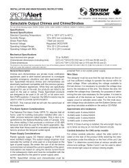
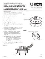
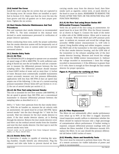
[6.1.4] <strong>Air</strong> Flow Test using Dwyer Series 607<br />
Differential Pressure Transmitter<br />
Verify the air speed of the duct using an anemometer. <strong>Air</strong><br />
speed must be at least 100 FPM. Wire the Dwyer transmitter<br />
as shown in Figure 6. Connect the leads of the meter<br />
to either side of the 1000Ω resistor. Allow unit to warm up<br />
for 15 seconds. With both HIGH and LOW pressure ports<br />
open to ambient air, measure and record the voltage drop<br />
acrossthe 1000Ω resistor (measurement 1), 4.00 volts is<br />
typical. Using flexible tubing and rubber stoppers, connect<br />
the HIGH side of the transmitter to the inlet sampling tube<br />
of the duct smoke detector housing, and the LOW side of<br />
the transmitter to the exhaust sampling tube of the duct<br />
smoke detector housing. Measure and record the voltage<br />
drop across the 1000Ω resistor (measurement 2). Subtract<br />
the voltage recorded in measurement 1 from the voltage<br />
recorded in measurement 2. If the difference is greater than<br />
0.15 volts, there is enough air flow through the duct smoke<br />
detector for proper operation.<br />
Figure 6. Procedure for verifying air flow:<br />
HIGH<br />
DIFFERENTIAL<br />
PRESSURE<br />
TRANSMITTER<br />
MODEL #607-01<br />
LOW<br />
1000 OHM 5% 1 WATT RESISTOR<br />
TO SAMPLING TUBE<br />
TO EXHAUST TUBE<br />
9 VOLT<br />
BATTERY<br />
15 TO 36VDC<br />
SUPPLY<br />
9 VOLT<br />
BATTERY<br />
9 VOLT<br />
BATTERY<br />
Drill a 1 ⁄4″ hole 3 feet upstream from the duct smoke detector.<br />
With the air handler on, measure the air velocity <strong>with</strong><br />
an anemometer. <strong>Air</strong> speed must be at least 100 FPM. Spray<br />
aerosol smoke* into the duct through the 1 ⁄4″ hole for five<br />
seconds. Wait two minutes for the duct smoke detector to<br />
alarm. If the duct smoke detector alarms, air is flowing<br />
through the detector. Remove the duct smoke detector cover<br />
and blow out the residual aerosol smoke from the chamber<br />
and reset the duct smoke detector. Use duct tape to seal the<br />
aerosol smoke entry hole.<br />
*Aerosol smoke can be purchased from Home Safeguard Industries,<br />
Malibu, CA. Phone: 310/457-5813.<br />
VOLT METER<br />
FLUKE MODEL 87<br />
OR EQUIVALENT<br />
H0163-01<br />
[6.1.5] Filter Replacement<br />
The filters do not substantially affect smoke performance<br />
even when up to 90% of the filter is clogged. Quarterly<br />
visual inspection usually suffices to determine whether the<br />
filters should be replaced because only a high percentage<br />
of contamination affects performance. If further testing is<br />
required, compare differential pressure readings <strong>with</strong> and<br />
<strong>with</strong>out the filters installed. If the difference exceeds 10%<br />
replace the filters. In no case should the pressure differential<br />
fall below 0.0015 inches of water.<br />
[6.1.3] <strong>Smoke</strong> Entry Test<br />
To determine if smoke is capable of entering the sensing<br />
chamber, visually identify any obstructions. Plug the<br />
[6.2] Standby, Alarm and Sensitivity Tests<br />
The cover must be removed to perform these tests. The use<br />
exhaust and inlet tube holes to prevent ducted air from<br />
of a remote accessory for visible indication of power and<br />
alarm is recommended.<br />
D200-33-00 4 I56-1944-07