DH100ACDCLPX Air Duct Smoke Detector with Extended Air Speed ...
DH100ACDCLPX Air Duct Smoke Detector with Extended Air Speed ...
DH100ACDCLPX Air Duct Smoke Detector with Extended Air Speed ...

Create successful ePaper yourself
Turn your PDF publications into a flip-book with our unique Google optimized e-Paper software.
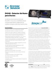
Figure 3. <strong>Air</strong> duct detector sampling tube:<br />
Figure 5. Sampling tube filter installation:<br />
AIR HOLES<br />
STOP SCREW<br />
SAMPLING<br />
TUBE<br />
END<br />
CAP<br />
MOUNTING HOLES<br />
AT 90° INCREMENTS<br />
AIR FLOW DIRECTION<br />
H0171-00<br />
Sampling tubes for this product are designed to be inserted<br />
from the outside, <strong>with</strong>out removing the cover, prior to<br />
installing the detector into its application.<br />
1. Install the end cap into the end of the tube farthest from<br />
the stop screw.<br />
2. Slide the tube into whichever bushing will be used for the<br />
air inlet, and push it all the way to the stop. The end of<br />
the tube <strong>with</strong> the four small holes goes into the bushing.<br />
3. Rotate the tube so that the holes face into the airflow,<br />
then adjust until the hole in the bushing lines up <strong>with</strong><br />
one of the four mounting holes in the tube.<br />
4. Secure the tube by inserting a #6 × 3 ⁄4˝ sheet metal<br />
screw through the hole in the bushing and the mounting<br />
hole in the tube. See Figure 4.<br />
Figure 4. Sampling tube connected to duct smoke<br />
detector:<br />
A78-2752-00<br />
[5.4] Install the <strong>Detector</strong> Housing<br />
Feed the sampling tube and the exhaust port through the predrilled<br />
holes in the mounting location, then use two screws<br />
to secure the housing to the mounting surface.<br />
Caution: Do not overtighten the screws.<br />
[5.5] <strong>Air</strong> Filters<br />
<strong>Air</strong> filters must be installed in both the inlet and exhaust<br />
openings inside the detector. These filters are initially<br />
installed at the factory. To remove for cleaning. loosen the<br />
holding tab and pull the filter out. Replace the filters by<br />
pushing them into the sampling and exhaust tube holes, as<br />
shown in Figure 5, then replacing the holding tabs.<br />
CAUTION<br />
H0131-00<br />
Filters require periodic cleaning or replacement, depending<br />
on the amount of dust and dirt accumulated. Visually<br />
inspect the filters at least quarterly; inspect them more<br />
often if the dust accumulation warrants it. See Section [6]<br />
for more information. Replacement filters can be ordered<br />
from System Sensor, 3825 Ohio Ave., St. Charles, IL 60174.<br />
(Exhaust tube/intake tube filter P/N F36-09-11)<br />
[5.6] Field Wiring<br />
Installation Guidelines<br />
All wiring must be installed in compliance <strong>with</strong> the<br />
National Electrical Code and the local codes having jurisdiction.<br />
Proper wire gauges should be used. The conductors<br />
used to connect smoke detectors to control panels and<br />
accessory devices should be color-coded to prevent wiring<br />
mistakes. Improper connections can prevent a system from<br />
responding properly in the event of a fire.<br />
For signal wiring, (the wiring between interconnected<br />
detectors or from detectors to auxiliary devices), it is<br />
usually recommended that single conductor wire be no<br />
smaller than 18 gauge. The duct smoke detector terminals<br />
accommodate wire sizes up to 12 gauge.<br />
<strong>Smoke</strong> detectors and alarm system control panels have<br />
specifications for allowable loop resistance. Consult the<br />
control panel manufacturer’s specifications for the total<br />
loop resistance allowed for the particular model control<br />
panel being used before wiring the detector loop.<br />
Wiring Instructions<br />
The <strong>DH100ACDCLPX</strong> detectors are designed for easy wiring.<br />
The housing provides a terminal strip <strong>with</strong> clamping<br />
plates. Wiring connections are made by stripping about 3 ⁄8″<br />
of insulation from the end of the wire, sliding the bare end<br />
under the plate, and tightening the clamping plate screw.<br />
[5.7] Perform <strong>Detector</strong> Check<br />
1. Perform STANDBY AND TROUBLE TEST per Section<br />
[6.2.1].<br />
2. Perform MAGNET TEST per Section [6.2.2.1]. The<br />
RTS451 test of Section [6.2.2.2] may substitute for this<br />
requirement.<br />
3. Perform AIR FLOW TEST per Section [6.1.1].<br />
4. Perform SMOKE RESPONSE TEST per Section [6.1.2].<br />
5. Perform SENSITIVITY TEST per Section [6.2.3].<br />
D200-33-00 3 I56-1944-07