DH100ACDCLPX Air Duct Smoke Detector with Extended Air Speed ...
DH100ACDCLPX Air Duct Smoke Detector with Extended Air Speed ...
DH100ACDCLPX Air Duct Smoke Detector with Extended Air Speed ...

Create successful ePaper yourself
Turn your PDF publications into a flip-book with our unique Google optimized e-Paper software.
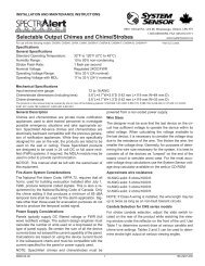
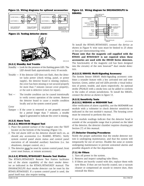
Figure 11. Wiring diagrams for optional accessories:<br />
<br />
<br />
<br />
<br />
<br />
<br />
<br />
<br />
<br />
<br />
<br />
<br />
<br />
<br />
Figure 13. Testing detector alarm:<br />
<br />
<br />
<br />
<br />
<br />
<br />
<br />
<br />
A78-2742-00<br />
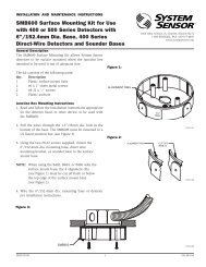
Figure 12. Wiring diagram for <strong>DH100ACDCLPX</strong> to<br />
SSK451:<br />
SSK451<br />
COMMON 3<br />
TEMPORAL SELECT 2<br />
ALARM SIGNAL 1<br />
SUPERVISORY SIGNAL 4<br />
RESET 7<br />
TEST 8<br />
POWER (–) 6<br />
POWER (+) 5<br />
FIELD INSTALLED<br />
JUMPER FOR<br />
TEMPORAL PATTERN<br />
15 ALARM SIGNAL<br />
3<br />
NO<br />
14<br />
<strong>DH100ACDCLPX</strong><br />
2 RESET<br />
11 TEST<br />
SUPERVISORY<br />
CONTACT<br />
20 AUX. POWER (–)<br />
19 AUX. POWER (+)<br />
H0130-00<br />
[6.2.1] Standby And Trouble<br />
Standby — Look for the presence of the flashing green LED. The<br />
LED should flash approximately every 10 seconds.<br />
Trouble — If the detector LED does not flash, then the detector<br />
lacks power (check wiring, panel, or power<br />
supply), the detector board is missing (replace),<br />
the cover has been missing or not secured properly<br />
for more than 7 minutes (secure cover properly),<br />
or the unit is defective (return for repair).<br />
Test — The trouble condition can be caused intentionally<br />
to verify correct operation of the system. Remove<br />
the detector board to cause a trouble condition<br />
locally and at the system control panel.<br />
Cover<br />
Tamper — If the cover is removed or not properly secured<br />
for a period longer than 7 minutes, a trouble<br />
signal is generated to indicate the cover is missing.<br />
[6.2.2] Alarm Tests<br />
[6.2.2.1] M02-04-00 Magnet Test<br />
1. Place the painted surface of the magnet onto the TEST<br />
locator on the bottom of the housing (Figure 13).<br />
2. The red alarm LED on the detector should latch on, as<br />
should any accessories (i.e. RA400Z, RTS451). Verify<br />
system control panel alarm status and control panel<br />
execution of all intended auxiliary functions (i.e. fan<br />
shutdown, damper control, etc.).<br />
3. The detector must be reset by system control panel, front<br />
cover reset button, or remote accessory.<br />
[6.2.2.2] RTS451/RTS451KEY Remote Test Station<br />
The RTS451/RTS451KEY Remote Test Station facilitates<br />
test of the alarm capability of the duct smoke detector<br />
as indicated in the RTS451/RTS451KEY manual. The<br />
<strong>DH100ACDCLPX</strong> duct smoke detector can be reset by the<br />
RTS451/RTS451KEY. If a system control panel is used, the<br />
panel itself may also require testing.<br />
FIELD INSTALLED<br />
JUMPER<br />
A78-2743-00<br />
To install the RTS451/RTS451KEY, connect the device as<br />
shown in Figure 9; wire runs must be limited to 25 ohms<br />
or less per interconnecting wire.<br />
Please note that the magnetic coil supplied <strong>with</strong> the<br />
RTS451 and RTS451KEY is not required when these<br />
accessories are used <strong>with</strong> the DH100 Series detectors.<br />
The functionality of the magnetic coil has been designed<br />
into the circuitry of the new Innovair duct smoke detectors.<br />
[6.2.2.3] SSK451 Multi-Signaling Accessory<br />
The System Sensor SSK451 Multi-Signaling accessory combines<br />
a sounder feature <strong>with</strong> a key activated test and reset<br />
function. Green, amber and red LEDs provide a visual indication<br />
of power, trouble, and alarm respectively. An optional<br />
strobe (PS24LO) <strong>with</strong> a smoke lens can be added to conform<br />
to the codes of certain jurisdictions. To install the SSK451,<br />
connect the device as shown in figure 13.<br />
[6.2.3] Sensitivity Tests<br />
[6.2.3.1] MOD400 or MOD400R Test<br />
After verification of alarm capability, use the MOD400R test<br />
module <strong>with</strong> a voltmeter to check detector sensitivity as<br />
indicated in the test module’s manual. The housing cover<br />
must be removed to perform this test.<br />
If test module readings indicate that the detector head is<br />
outside of the acceptable range that is printed on the label<br />
of the detector, the detector chamber requires cleaning per<br />
Section [7] of this manual.<br />
[7] <strong>Detector</strong> Cleaning Procedures<br />
Notify the proper authorities that the smoke detector system<br />
is undergoing maintenance, and that the system will<br />
temporarily be out of service. Disable the zone or system<br />
undergoing maintenance to prevent unwanted alarms and<br />
possible dispatch of the fire department.<br />
[7.1] <strong>Air</strong> Filters<br />
1. Turn off power to the system.<br />
2. Remove and inspect sampling tube filters.<br />
3. If filters are heavily coated <strong>with</strong> dirt, replace them <strong>with</strong><br />
new filters. If they are not heavily coated, use a vacuum<br />
cleaner or compressed air nozzle to remove dust, then<br />
reinstall the filters.<br />
D200-33-00 6 I56-1944-07