Canalis busbar trunking (ENG) - Trinet
Canalis busbar trunking (ENG) - Trinet
Canalis busbar trunking (ENG) - Trinet

You also want an ePaper? Increase the reach of your titles
YUMPU automatically turns print PDFs into web optimized ePapers that Google loves.
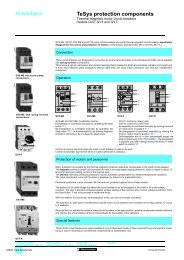
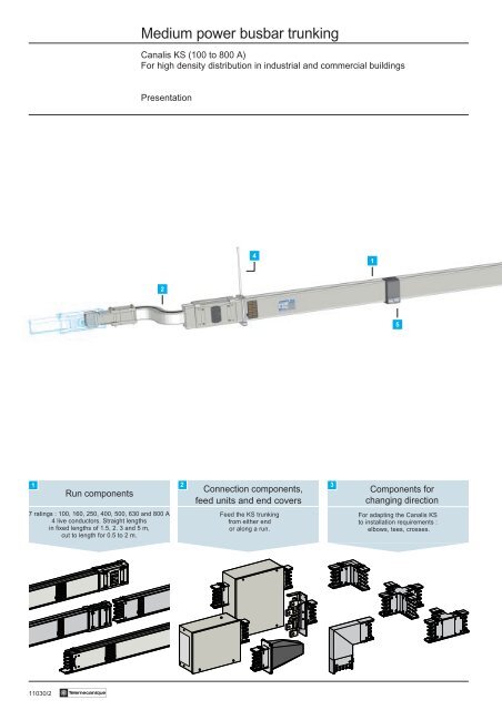
Medium power <strong>busbar</strong> <strong>trunking</strong><br />
<strong>Canalis</strong> KS (100 to 800 A)<br />
For high density distribution in industrial and commercial buildings<br />
Presentation<br />
4<br />
1<br />
2<br />
5<br />
1<br />
Run components<br />
7 ratings : 100, 160, 250, 400, 500, 630 and 800 A<br />
4 live conductors. Straight lengths<br />
in fixed lengths of 1.5, 2. 3 and 5 m,<br />
cut to length for 0.5 to 2 m.<br />
2 3<br />
Connection components,<br />
feed units and end covers<br />
Feed the KS <strong>trunking</strong><br />
from either end<br />
or along a run.<br />
Components for<br />
changing direction<br />
For adapting the <strong>Canalis</strong> KS<br />
to installation requirements :<br />
elbows, tees, crosses.<br />
11030/2 Te
0<br />
1<br />
4<br />
3<br />
4<br />
5<br />
1<br />
4<br />
5<br />
2<br />
4 5 6<br />
Fixing brackets<br />
Tap-off units<br />
Accessories<br />
For fixing<br />
KS <strong>trunking</strong>.<br />
25 to 400 A connectors and<br />
fused tap-off units, circuit-breakers<br />
or modular equipment.<br />
Dust and damp proofing accessories.<br />
Te 11030/3
Medium power <strong>busbar</strong> <strong>trunking</strong><br />
Selection guide:<br />
pages 11032/2 to 11032/4<br />
Characteristics :<br />
page 11032/5<br />
References :<br />
pages 11033/3 to 11038/3<br />
Dimensions :<br />
pages 11040/2 to 11042/3<br />
<strong>Canalis</strong> KS (100 to 800 A)<br />
Description<br />
General<br />
<strong>Canalis</strong> KS is designed for medium power distribution with high tap-off density in industrial and commercial buildings<br />
(exhibition halls, hypermarkets, office blocks, etc.).<br />
The range is available in 7 ratings from 100 to 800 A.<br />
The standard IP 52 degree of protection makes KS suitable for the majority of locations. It can be increased to IP 54 by<br />
the addition of dust and damp proof blanking plates on the tap-off outlets.<br />
Tapping off is via tap-off units. These units, from 25 to 400 A, can be safely removed while live.<br />
100 to 250 A <strong>trunking</strong> can take connectors and tap-off units up to 250 A.<br />
Higher rated <strong>trunking</strong> can take any tap-off unit from the range.<br />
Run components<br />
Straight distribution lengths<br />
2 1 3 4 5 6<br />
Straight lengths are designed to carry current and feed loads with low or medium power. The straight lengths form the<br />
structure of the run. They comprise :<br />
1 A casing of galvanised sheet steel, which is crimped closed.<br />
This casing, shaped and ribbed by rolling, provides excellent resistance to bending and twisting.<br />
Three casing widths cover the whole range. Casings are available in two finishes :<br />
- 54 mm wide galvanised sheet steel for 100, 160 and 250 A ratings (sheet steel with RAL 7032 grey finish available<br />
as an option).<br />
- 75 mm wide sheet steel with RAL 7032 grey finish for 400 and 500 A ratings.<br />
- 113 mm wide sheet steel with RAL 7032 grey finish for 630 and 800 A ratings.<br />
2 4 live conductors of the same cross-section :<br />
- Bimetal silver-plated copper/aluminium laminate for 100, 160 A ratings.<br />
- Aluminium fitted with bimetal silver-plated copper/aluminium laminate riders electrically welded to junctions and tapoff<br />
positions for 250 to 800 A ratings.<br />
The lamination is a patented process by which the copper and aluminium molecules are fused together under extreme<br />
pressure.<br />
3 Fibreglass reinforced polyester isolators, at 250 mm intervals.<br />
These hold the conductors securely within the casing.<br />
4 A special protected earth (PE) conductor of the same type as the live conductors with a cross-section ≥ 1/2 of the phase<br />
cross-section. It is connected to the casing at each junction.<br />
5 Tap-off outlets on both sides of the <strong>trunking</strong>, at 1 m intervals.<br />
They are connected to the isolators to form a block, holding the bars. They have a shuttered outlet which is opened<br />
and closed automatically when connectors or tap-off units are plugged in or removed.<br />
6 A mechanical and electrical jointing device.<br />
Electrical connection is via a block with spring and silver graphite contacts. This block absorbs the differential<br />
conductor/casing expansion of each length equally.<br />
For 100, 160 and 250 A ratings, it automatically and simultaneously connects all the live conductors, ensures<br />
continuity of the protective earth conductor and its connection with the casing. For higher ratings (315 to 800 A), the<br />
electrical connection is made by a 1/4 screw turn for each conductor.<br />
11031/2 Te
Medium power <strong>busbar</strong> <strong>trunking</strong><br />
Selection guide:<br />
pages 11032/2 to 11032/4<br />
Characteristics :<br />
page 11032/5<br />
References :<br />
pages 11033/3 to 11038/3<br />
Dimensions :<br />
pages 11040/2 to 11042/3<br />
<strong>Canalis</strong> KS (100 to 800 A)<br />
Description<br />
Special components<br />
i Fire barrier length<br />
To cross a fire partition, between two areas of a building. Fire resistance : 2 h (A120) conforming to ISO 834.<br />
i “Made to measure” length<br />
To alter the length of a run (for example, between two components for changing direction). These components are<br />
manufactured, on request, from 500 mm to 1995 mm, in multiples of 5 mm. They do not have tap-off outlets.<br />
Connection components and feed units<br />
Feed units<br />
To feed a KS run by cables or directly from a distribution panel. The feed can be from one end (end feed) or along a run<br />
(centre feed). They can be connected by aluminium or copper cables fitted with suitable cable lugs. There is an undrilled<br />
aluminium gland plate which will accept cable glands. This plate can be replaced by a plate fitted with 1 to 3 cable clamps<br />
depending on the rating (to be ordered separately).<br />
2<br />
1 End feed box<br />
For 100 A <strong>busbar</strong> <strong>trunking</strong> only. It<br />
is mounted to the left or right of a<br />
straight length and fitted with a<br />
no. 29 cable gland.<br />
1<br />
2 End feed units<br />
For 100 to 250 A ratings : mounted<br />
to the left or right of a straight<br />
length, by inverting the initial<br />
section of the <strong>trunking</strong>.<br />
For 400 to 800 A ratings : available<br />
in left or right hand versions.<br />
4<br />
3<br />
3 Centre feed unit<br />
“Through run” type (1 cable feeds<br />
the right and left sections). It is<br />
mounted along the run, between 2<br />
straight lengths.<br />
4 Flange feed unit<br />
Fitted with splayed bars and a<br />
mounting plate. It is used for<br />
connection to a distribution panel.<br />
It can be mounted at either end of<br />
a component.<br />
Te 11031/3
Medium power <strong>busbar</strong> <strong>trunking</strong><br />
Selection guide :<br />
pages 11032/2 to 11032/4<br />
Characteristics :<br />
page 11032/5<br />
References :<br />
pages 11033/3 to 11038/3<br />
Dimensions :<br />
pages 11040/2 to 11042/3<br />
<strong>Canalis</strong> KS (100 to 800 A)<br />
Description<br />
Connection components and feed units (continued)<br />
KV-KS connector<br />
The KV-KS connector is fitted with a<br />
KV end length at one end and a KS<br />
end length at the other.<br />
Due to its flexible design, it ensures<br />
direct connection from a feed run to a<br />
distribution run and reduces any risk<br />
caused by alignment faults.<br />
End cover<br />
The end cover protects and isolates<br />
the ends of the conductors. It is<br />
mounted on the last length.<br />
Three products cover the entire KS<br />
range : 100 to 250 A, 400 and 500 A,<br />
630 and 800 A.<br />
Components for changing direction<br />
2<br />
1<br />
1 Edgewise elbow.<br />
One model for each size of<br />
casing for turning to left or right.<br />
2 Flat elbow<br />
Two models for each size of<br />
casing (one ascending, one descending).<br />
Flat and edgewise elbows can<br />
be manufactured, on request,<br />
with “made to measure” connection<br />
lengths, with multiple<br />
angles, with built-in fire barrier,<br />
etc. (please consult your Regional<br />
Sales Office).<br />
3<br />
3 Edgewise tee and cross<br />
For vertical branches on the main<br />
run.<br />
Fixing devices<br />
(630 1 (630 - 800) - 800)<br />
(400…500) (315…500)<br />
(100…250) (100…250)<br />
1 Universal brackets<br />
These brackets are used to fix the<br />
distribution run to the structure of<br />
the building, directly or via a<br />
threaded rod, a bracket, etc.<br />
There is one model for each size of<br />
casing which can be used for all<br />
mounting methods : ceilingmounted,<br />
suspended, wallmounted,<br />
etc.<br />
Suspension on chains or steel cables<br />
is not recommended.<br />
It is advisable to leave a space of 3<br />
m between each bracket.<br />
11031/4 Te
Medium power <strong>busbar</strong> <strong>trunking</strong><br />
Selection guide :<br />
pages 11032/2 to 11032/4<br />
Characteristics :<br />
page 11032/5<br />
References :<br />
pages 11033/3 to 11038/3<br />
Dimensions :<br />
pages 11040/2 to 11042/3<br />
<strong>Canalis</strong> KS (100 to 800 A)<br />
Description<br />
Tap-off units<br />
These are used for instant connection of loads or secondary runs (for example, for low power distribution using <strong>Canalis</strong><br />
KN). The connectors and tap-off units conform to installation standards and regulations whatever type of neutral point<br />
connection is used (TT, IT, TNS or TNC).<br />
i They can be removed and moved whilst live, with no load.<br />
i The tap-off outlets are opened and closed automatically when units are plugged in or removed.<br />
i With the cover open, no live part can be accessed. Degree of protection IP 2X.<br />
i Connectors and tap-off units are made in two versions :<br />
- Protected version, degree of protection IP 40, suitable for most industrial and commercial applications,<br />
- Dust and damp proof version, degree of protection IP 54, for very dusty locations and environments, or those subject<br />
to water splashes.<br />
A<br />
B<br />
PE =<br />
A<br />
B<br />
Tap-off unit<br />
- Isolation is achieved by<br />
unplugging the tap-off.<br />
- The electrical equipment and<br />
connection terminals can only be<br />
accessed with the tap-off<br />
unplugged.<br />
- A safety device prevents the tapoff<br />
being plugged into the <strong>trunking</strong><br />
if the cover is not in place.<br />
Tap-off units with isolator<br />
Isolation (AC22 to AC 20) is<br />
achieved by opening the cover of<br />
the unit. A number of safety devices<br />
prevent the following :<br />
- Connection of the tap-off unit if<br />
the cover is closed,<br />
- Opening of the cover if the unit is<br />
not locked to the <strong>trunking</strong>,<br />
- Removal of the unit if the cover is<br />
closed,<br />
- Opening of the cover to position<br />
“I” (by locking) on units which have<br />
a switch or circuit-breaker.<br />
These tap-off units will take<br />
accessories such as an early break<br />
contact on the cover, a sealing kit,<br />
etc. (see page 11043/3).<br />
Tap-off<br />
1 Tap-off with fuse carrier<br />
The tap-off is protected by means of<br />
fuses (not supplied).<br />
They can be fitted with carriers for the<br />
following fuses :<br />
- NF 10 x 38<br />
- BS type 88A1<br />
- DIN type Neozed DO1<br />
1<br />
2<br />
2 Tap-off for modular equipment<br />
This tap-off will take most 17.5 mm<br />
modular equipment.<br />
- Nominal current : 25 A,<br />
- Capacity : 4 modules,<br />
- With window in front panel (equipment<br />
can be seen and accessed).<br />
Te 11031/5
Medium power <strong>busbar</strong> <strong>trunking</strong><br />
Selection guide :<br />
pages 11032/2 to 11032/4<br />
Characteristics :<br />
page 11032/5<br />
References :<br />
pages 11033/3 to 11038/3<br />
Dimensions :<br />
pages 11040/2 to 11042/3<br />
<strong>Canalis</strong> KS (100 to 800 A)<br />
Description<br />
Tap-off units (continued)<br />
Fused tap-off units<br />
1<br />
2<br />
3<br />
These fused tap-off units are designed<br />
to protect the tap-off by means of<br />
fuses (not supplied).<br />
They can be fitted with carriers for the<br />
following fuses :<br />
- NF and DIN, 50 to 630 A,<br />
- BS, 30 to 160 A,<br />
- VDE and DIN, 25 to 400 A.<br />
Versions for NF fuses can be fitted<br />
with a single phase protection device.<br />
1 25 to 125 A fused off-load tap-off unit.<br />
2 160 A fused off-load tap-off unit.<br />
3 250 to 400 A fused off-load tap-off<br />
unit.<br />
These units can only be mounted on<br />
<strong>trunking</strong> which is installed horizontally<br />
on edge.<br />
To make installation easier, it is<br />
performed in two stages :<br />
- The unit is hooked onto the <strong>trunking</strong>,<br />
then automatically located in front of<br />
the tap-off outlet by moving it<br />
sideways.<br />
- The fixing brackets are then locked<br />
and the mobile power block plugged<br />
in, using an internal device.<br />
Tap-off units with isolator for modular equipment<br />
These units will take most 17.5<br />
modular equipment. They have a<br />
window in the front panel (equipment<br />
can be seen and accessed).<br />
There are two ratings :<br />
- 50 A nominal current, capacity 7.5<br />
modules,<br />
- 100 A nominal current, capacity 11<br />
modules.<br />
11031/6 Te
0<br />
1<br />
Medium power <strong>busbar</strong> <strong>trunking</strong><br />
Selection guide :<br />
pages 11032/2 to 11032/4<br />
Characteristics :<br />
page 11032/5<br />
References :<br />
pages 11033/3 to 11038/3<br />
Dimensions :<br />
pages 11040/2 to 11042/3<br />
<strong>Canalis</strong> KS (100 to 800 A)<br />
Description<br />
Tap-off units for Merlin Gerin circuit-breaker<br />
These units are designed to take Merlin<br />
Gerin Compact NS circuit-breakers :<br />
- 100 to 400 A rating,<br />
- Fixed, with front sockets,<br />
- Version N, H or L,<br />
- With or without residual differential<br />
device,<br />
- With rotary switch.<br />
For other types of circuit-breaker :<br />
please consult your Regional Sales<br />
Office.<br />
Tap-off unit for integral contactor-breaker<br />
This unit is designed to take<br />
Telemecanique integral contactorbreakers<br />
and inverters.<br />
Isolating tap-off unit for industrial control and monitoring equipment<br />
This unit has a “Telequick” mounting<br />
plate and will take industrial control<br />
and monitoring equipment (for<br />
example, for controlling lighting in<br />
hypermarkets).<br />
Nominal current : 125 A.<br />
Two sizes :<br />
- With 300 x 300 mm mounting plate,<br />
- With 400 x 600 mm mounting plate.<br />
IP 54 dust and damp proofing accessories<br />
1<br />
In normal mounting position (edgewise,<br />
horizontal installation) the degree of<br />
protection of the KS range is IP 52.<br />
In other positions (flat and vertical<br />
installation) the degree of protection is<br />
reduced to IP 50.<br />
To achieve a higher degree of<br />
protection, IP 54, the following<br />
accessories must be added to the<br />
straight lengths.<br />
2<br />
1<br />
Edgewise horizontal installation<br />
1 Each tap-off outlet which is not<br />
being used should be fitted with a<br />
sealed tap-off blanking plate.<br />
Flat and vertical installation<br />
1 Each tap-off outlet which is not<br />
being used should be fitted with a<br />
sealed tap-off blanking plate.<br />
2 Each junction between<br />
components should be fitted with a<br />
jointing sleeve.<br />
Te 11031/7
Medium power <strong>busbar</strong> <strong>trunking</strong><br />
Description :<br />
pages 11031/2 to 11031/7<br />
Characteristics :<br />
page 11032/5<br />
References :<br />
pages 11033/3 to 11038/3<br />
Dimensions :<br />
pages 11040/2 to 11042/3<br />
<strong>Canalis</strong> KS (100 to 800 A)<br />
Selection guide<br />
Information required<br />
i The types of load, and their characteristics and locations.<br />
i The power source, and its characteristics and location.<br />
i The structure of the premises (availability of fixing points<br />
for <strong>trunking</strong>).<br />
i Any influences external to the installation site.<br />
(ambient temperature, dust, water, etc).<br />
Distribution run layout<br />
The siting of distribution runs depends on the position of the loads, the location of the general power supply and the<br />
availability of fixing points.<br />
A single distribution run can serve an area 5 to 8 metres wide.<br />
Selection of the <strong>trunking</strong> according to the rated operating current Ib<br />
Ib = total current x k1<br />
Total current = sum of currents drawn by the loads on a run<br />
k1 = average demand coefficient<br />
Applications k1 Rated operating current Ib Selected <strong>trunking</strong><br />
Lighting, heating 1 0...100 A KSi-10<br />
100...160 A KSi-16<br />
Distribution (Engineering shop floors) 160...250 A KSi-25<br />
2 or 3 loads 0.9 315...400 A KSi-40<br />
4 or 5 loads 0.8 400...500 A KSi-50<br />
6...9 loads 0.7 500...630 A KSi-63<br />
10...40 loads 0.6 630...800 A KSi-80<br />
40 or more 0.5<br />
Permissible current Iz according to the ambient temperature (at the installation site)<br />
The nominal current Inc of the <strong>trunking</strong> is specified for an average daily ambient temperature of 35 °C (and a maximum<br />
of 40°C). Depending on the actual temperature, an uprating or derating coefficient (f1) may be applied to the nominal<br />
current Inc : see the characteristics on page 11032/5.<br />
Checking the voltage drop<br />
The voltage drop in <strong>Canalis</strong> KS is given in V/100m/A in the characteristics table on page 11032/5.<br />
Polarity selection<br />
3-pole distribution + N + PE (IT-TT-TNS)<br />
3L + PE<br />
(IT-TT-TNS)<br />
3L + N + PE<br />
(IT-TT-TNS)<br />
i KSA-iiED4ii <strong>trunking</strong><br />
3-pole + N + PE<br />
tap-offs possible, type 3-pole + PE<br />
or 3-pole + N + PE<br />
3-pole distribution + PEN (TNC)<br />
i KSA-iiED4ii <strong>trunking</strong><br />
3-pole + PEN<br />
tap-offs possible, type 3-pole + PEN (TNC) or 3-pole +<br />
N + PE (TNS)..<br />
3L + PEN<br />
(TNC)<br />
3L + N + PE<br />
(TNS)<br />
11032/2 Te
Medium power <strong>busbar</strong> <strong>trunking</strong><br />
Description :<br />
pages 11031/2 to 11031/7<br />
Characteristics :<br />
page 11032/5<br />
References :<br />
pages 11033/3 to 11038/3<br />
Dimensions :<br />
pages 11040/2 to 11042/3<br />
<strong>Canalis</strong> KS (100 to 800 A)<br />
Selection guide<br />
Protecting the <strong>trunking</strong> against overloads<br />
To enable it to be extended, prefabricated <strong>busbar</strong> <strong>trunking</strong> is generally protected to its nominal current Inc (or to its<br />
permissible current Iz if the f1 coefficient is applied according to the ambient temperature).<br />
Protection using fuses<br />
i Calculate the standard nominal current In of the fuse so that : In ≤ Inc<br />
1<br />
i Select the standard rating In which is equal to or immediately below.<br />
Check that In ≥ Ib. If this is not the case, select the next highest rating of <strong>trunking</strong>.<br />
Note : Protecting <strong>trunking</strong> using fuses is the same as limiting the rated operating current.<br />
Protection using a circuit-breaker<br />
i Select the circuit-breaker setting current Ir so that : Ib ≤ Ir ≤ Inc<br />
Note : Protecting <strong>trunking</strong> using a circuit-breaker makes it possible to use the <strong>trunking</strong> at full capacity.<br />
Electrodynamic protection against short-circuit currents<br />
The electrodynamic withstand of the <strong>trunking</strong> should be taken into account when selecting a protective device<br />
(permissible rated peak current).<br />
i Determine (1) the 3-phase short-circuit current, prospective lcc 3 (KA) at the start of the <strong>Canalis</strong> KS.<br />
i Check, on the current limitation curve of the selected protective device, that this limits the peak current (kÂ) to a value<br />
below the permissible rated peak current of the KS <strong>trunking</strong>.<br />
Limited current ≤ <strong>Canalis</strong> current<br />
Protection using a Merlin Gerin Compact circuit-breaker<br />
The circuit-breaker/<strong>Canalis</strong> coordination table below gives the maximum short-circuit current for which the KS <strong>trunking</strong><br />
is protected, according to the type of circuit-breaker.<br />
Prospective Icc 3, max (Ka rms) voltage 380/415 V<br />
<strong>Canalis</strong> KS : rating (A) 100 160 250 400 500 630 800<br />
Type of NS100 N 25<br />
Merlin Gerin H 25<br />
circuit-breaker L 25<br />
NS160 N 20 36<br />
H 20 70<br />
L 20 70<br />
NS250 N 36 36<br />
H 55 70<br />
L 55 150<br />
NS400 N 45 45<br />
H 45 70<br />
L 45 150<br />
NS630 N 45 45 45<br />
H 70 70 70<br />
L 150 150 150<br />
C801 N 40 50<br />
H 40 50<br />
L 55 50<br />
C1001 N 50<br />
H 50<br />
L 80<br />
(1) By calculation or using graphs, precalculated tables, etc.<br />
Te 11032/3
Medium power <strong>busbar</strong> <strong>trunking</strong><br />
Selection guide :<br />
page 11032/2<br />
Caracteristiques :<br />
page 11032/5<br />
References :<br />
pages 11033/3 to 11038/3<br />
Dimensions :<br />
pages 11040/2 to 11042/3<br />
<strong>Canalis</strong> KS (100 to 800 A)<br />
Selection guide<br />
Selection of IP degree of protection<br />
External influences are taken into consideration when siting the installation.<br />
The IP 52 degree of protection of <strong>Canalis</strong> KS means that it is suitable for installation in most industrial and commercial<br />
locations.<br />
For locations or sites which may be subject to water splashes in any direction the degree of protection should be raised<br />
to IP 54, by installing KSE-80YB2 sealed tap-off blanking plates (see page 11043/2).<br />
Changing levels in horizontal distribution<br />
KSA-●●LP42<br />
KSE-●●YAi<br />
KSA-●●LP41<br />
When <strong>trunking</strong> is mounted vertically,<br />
the degree of protection at a junction<br />
is IP 50.<br />
To maintain a degree of protection<br />
higher than IP 50, if required, each<br />
junction installed vertically must be<br />
fitted with a sealed jointing sleeve<br />
(IP 54).<br />
(See page 11043/2).<br />
Tap-off units<br />
n<br />
There are 2 ranges of tap-off units.<br />
i IP 40 protected range, low-cost and<br />
suitable for normal industrial and<br />
commercial environments.<br />
i IP 54 dust and damp proof range, for<br />
very dusty or damp environments.<br />
KSA-ii IP 40<br />
KSE-ii IP 54 n<br />
Mounting position<br />
Edgewise<br />
Flat<br />
The preferred mounting position (for<br />
horizontal distribution) is edgewise.<br />
In some installation configurations<br />
(false ceiling, false flooring, locations<br />
with very little space, etc.) it may be<br />
necessary to install <strong>trunking</strong> flat.<br />
There are several suggestions for this.<br />
Please consult your Regional Sales<br />
Office.<br />
Selecting the power supply<br />
i 100 A end feed and 250 A (160 A)<br />
feed unit<br />
- mounted at either end of a run,<br />
- all types of neutral system.<br />
B<br />
A<br />
i 500 and 800 A feed unit.<br />
Two types depending on position :<br />
- right hand mounting (fig. A),<br />
- left hand mounting (fig. B).<br />
All types of neutral system. Connected<br />
by means of lugs.<br />
11032/4 Te
Medium power <strong>busbar</strong> <strong>trunking</strong><br />
Description :<br />
pages 11031/2 to 11031/7<br />
Selection guide :<br />
page 11032/2<br />
References :<br />
pages 11033/3 to 11038/3<br />
Dimensions :<br />
pages 11040/2 to 11042/3<br />
<strong>Canalis</strong> KS (100 to 800 A)<br />
Characteristics (1)<br />
Type of <strong>trunking</strong> KSA-10 KSA-16 KSA-25 KSA-40 KSA-50 KSA-63 KSA-80<br />
General Characteristics<br />
Number of live conductors 3 or 4 3 or 4 3 or 4 3 or 4 3 or 4 3 or 4 3 or 4<br />
Rated thermal current lth A 100 160 250 400 500 630 800<br />
Rated insulation voltage V 660 660 660 660 660 660 660<br />
conforming to IEC 158-1<br />
Rated operating voltage V 660 660 660 660 660 660 660<br />
Rated frequency Hz 50/60 50/60 50/60 50/60 50/60 50/60 50/60<br />
Conductor characteristics<br />
Live conductors<br />
Rb0 ph<br />
Average resistance per mΩ/m 1.059 0.490 0.216 0.142 0.091 0.074 0.045<br />
conductor, cold state<br />
(ambient temperature 20 °C)<br />
Rb1 ph<br />
Average resistance per mΩ/m 1.395 0.661 0.294 0.190 0.123 0.101 0.061<br />
conductor at Ith<br />
(ambient temperature 35 °C)<br />
X ph<br />
Average reactance per mΩ/m 0.457 0.233 0.192 0.112 0.116 0.070 0.071<br />
conductor<br />
Z ph<br />
Average impedance per mΩ/m 1.468 0.701 0.351 0.221 0.170 0.123 0.094<br />
conductor<br />
Protective conductor<br />
Cross-section (copper equivalent) mm 2 66 78 78 127 127 247 247<br />
Average resistance, cold state mΩ/m 0.270 0.230 0.230 0.142 0.142 0.074 0.074<br />
(ambient temperature 20 °C)<br />
Fault loop impedance at 6 Ith<br />
Between live conductors mΩ/m 3.384 1.708 0.811 0.541 0.428 0.279 0.237<br />
Between live conductors and PE mΩ/m 2.090 1.139 0.720 0.512 0.439 0.317 0.289<br />
Other Characteristics<br />
Short-circuit withstand capacity<br />
Permissible rated peak current kA 13.6 22 28 49.2 55 67.5 78.7<br />
(3-phase)<br />
Permissible rated short time current kA rms 8 11 14 24.6 27.1 32.5 38.3<br />
(0.1 s)<br />
Maximum thermal limit A 2 s 6.8.10 6 20.2.10 6 100.10 6 354.10 6 733.10 6 1096.10 6 1798.10 6<br />
Degree of protection<br />
In normal mounting position. Horizontal, edgewise installation.<br />
Standard IP 52 IP 52 IP 52 IP 52 IP 52 IP 52 IP 52<br />
With sealing accessories IP 54 IP 54 IP 54 IP 54 IP 54 IP 54 IP 54<br />
Other positions : horizontal installation, flat, vertical installation.<br />
Standard IP 50 IP 50 IP 50 IP 50 IP 50 IP 50 IP 50<br />
With sealing accessories IP 54 IP 54 IP 54 IP 54 IP 54 IP 54 IP 54<br />
Voltage drop<br />
Composite voltage drop, hot state, expressed in V/100 m/A for 3-phase 50 Hz current, with load distributed along the<br />
run. Where the load is concentrated at the end of the feed run, the voltage drops are twice the values indicated in the<br />
table.<br />
For a power factor 0.7 V/100 m/A 0.112 0.055 0.030 0.0184 0.0146 0.0104 0.0081<br />
cos ϕ of 0.8 V/100 m/A 0.120 0.058 0.030 0.0190 0.0146 0.0106 0.0079<br />
0.9 V/100 m/A 0.126 0.060 0.030 0.0190 0.0140 0.0105 0.0074<br />
1.0 V/100 m/A 0.121 0.057 0.025 0.0164 0.0107 0.0087 0.0053<br />
Determination of permissible current Derating or uprating factor to be applied to the rated thermal current of the <strong>trunking</strong>where the average daily ambient<br />
lz for a <strong>busbar</strong> <strong>trunking</strong> system, temperature is other than 35 °C.<br />
according to ambient temperature<br />
Average ambient temperature °C 10 15 20 25 30 35 40 45 50 55 60<br />
Factor f1 1,10 1,08 1,06 1,04 1,02 1,00 0,97 0,94 0,91 0,88 0,85<br />
(1) Conforming to international standard IEC 439-2 and European standard EN 60439.2<br />
Te 11032/5
KSA-iiEDiii<br />
KSA-iiAB4ii<br />
KSA-iiEF4ii<br />
KSA-iiTC40<br />
KSA-iiEZi<br />
KSA-iiLC40<br />
KSA-iiEDiii<br />
KSB-iiFA2<br />
KSE-80YB2<br />
KSA/KSE-05SFii<br />
KSA/KSE-iiDBi11<br />
KSA-iiLC40<br />
KSA-iiES4A<br />
KSA-iiLP42<br />
11033/2<br />
Te<br />
KSA-iiLP41<br />
KSE-iiYAi
Medium power <strong>busbar</strong> <strong>trunking</strong><br />
Description :<br />
pages 11031/2 to 11031/7<br />
Selection guide :<br />
page 11032/2<br />
Characteristics :<br />
page 11032/5<br />
Dimensions :<br />
pages 11040/2 to 11040/5<br />
<strong>Canalis</strong> KS (100 to 250 A)<br />
References<br />
Run components (IP 52/IP 54) (1)<br />
Description Rating Length Number of 3L + N + PE and 3L + PEN Weight<br />
A mm tap-offs Reference kg<br />
Straight 100 5000 10 KSA-10EA450 19.050<br />
lengths<br />
3000 6 KSA-10EA430 11.900<br />
160 5000 10 KSA-16EA450 21.200<br />
3000 6 KSA-16EA430 13.200<br />
250 5000 10 KSA-25EA450 25.000<br />
3000 6 KSA-25EA430 15.500<br />
250 (2) 2000 8 KSA-25ED420 10.650<br />
1500 6 KSA-25ED415 8.350<br />
Straight length 250 (2) 500…1995 – KSA-25ES4A (3) 8.000/m<br />
cut to length<br />
Fire barrier 250(2) 1200…2200 – KSA-25EF4A (3) 8.000/m<br />
length<br />
Connection components and feed units (2)<br />
Description Rating Connection Mounting Reference Weight<br />
A Type/Max.cross-sect. kg<br />
End 100 Terminals/ Left or right KSA-10AB451 1.850<br />
feed unit 5 x 16 mm 2<br />
250 (2) Lugs/240 mm 2 Left or right KSA-25AB42 7.200<br />
(M10 screw)<br />
Centre 250 (2) Lugs/240 mm 2 Along the run KSA-25BT42 12.00<br />
feed unit (M10 screw)<br />
Flange 250 (2) Bars Left or right KSA-25ER4 1.700<br />
feed unit<br />
(M10 screw)<br />
KV-KS 250 (2) – – KV0-25ER41001<br />
connector<br />
N<br />
KV0-25ER41001<br />
End 250 (2) – Left or right KSB-25FA3 0.150<br />
cover<br />
Components for changing direction (4)<br />
Type Rating Mounting Reference Weight<br />
A<br />
kg<br />
Elbows 250 (2) Edgewise KSA-25LC40 3.150<br />
Flat upwards (1) KSA-25LP41 5.000<br />
Flat downwards (1) KSA-25LP42 5.000<br />
Tee 250 (2) Edgewise KSA-25TC40 4.300<br />
Cross 250 (2) Edgewise KSA-25XC40 5.000<br />
Fixing Device (Order in multiples of10)<br />
Bracket 250 (2) – KSA-25EZ1 0.300<br />
(1) IP 54 with sealing accessory : see page 11043/2.<br />
(2) This reference is suitable for 100 and 160 A ratings.<br />
(3) When ordering, state the required length in mm (in multiples of 5 mm) after the reference. Example : KSA-25ES4A L = 1250 mm.<br />
(4) Other components IP 54 as standard, common to versions of 3L+N+PE and 3L+PEN straight lengths.<br />
Te 11033/3
Medium power <strong>busbar</strong> <strong>trunking</strong><br />
Description :<br />
pages 11031/2 to 11031/7<br />
Selection guide :<br />
page 11032/2<br />
Characteristics :<br />
page 11032/5<br />
Dimensions :<br />
pages 11040/2 to 11040/5<br />
<strong>Canalis</strong> KS (400 and 500 A)<br />
References<br />
Run components (IP 52/IP 54) (1)<br />
Description Rating Length Number of 3L + N + PE and 3L + PEN Weight<br />
A mm tap-offs Reference kg<br />
Straight 400 5000 10 KSA-40ED450 40.000<br />
lengths<br />
3000 6 KSA-40ED430 25.000<br />
KSA-40ED450<br />
500 5000 10 KSA-50ED450 44.500<br />
3000 6 KSA-50ED430 28.000<br />
500 (400) 2000 6 KSA-50ED420 20.000<br />
1500 3 KSA-50ED415 15.900<br />
Straight length 500 (400) 500 to 1995 – KSA-50ES4A (3) 15 kg/m<br />
cut to length<br />
Fire barrier 500 (400) 1200 to 2340 – KSA-50EF4A (3) 15 kg/m<br />
length<br />
Connection components and feed units (2)<br />
Description Rating Connection Mounting Unit Weight<br />
A Type/Max cross-sect. reference kg<br />
End 500 (400) Lugs/2 x 300 mm 2 Right KSA-50AB452 22.000<br />
feed unit<br />
(M12 screw)<br />
KSA-50AB452<br />
Left KSA-50AB462 22.000<br />
Centre 500 (400) Lugs/2 x 300 mm 2 Along the run KSA-50BT402 39.000<br />
feed unit<br />
(M12 screw)<br />
Flange 500 (400) Bars Left or right KSA-50ER4 4.100<br />
feed unit<br />
(M12 screw)<br />
KV-KS 500 (400) – – KV0-50ER41001<br />
connector<br />
End 500 (400) – Left or right KSB-50FA2 0.440<br />
cover<br />
Components for changing direction (2)<br />
N<br />
KV0-50ER41001<br />
Description Rating Mounting Reference Weight<br />
A<br />
kg<br />
Elbows 500 (400) Edgewise KSA-50LC40 9.860<br />
Flat upwards (1) KSA-50LP41 10.000<br />
Flat downwards (1) KSA-50LP42 10.000<br />
Tee 500 (400) Edgewise KSA-50TC40 15.000<br />
Cross 500 (400) Edgewise KSA-50XC40 16.500<br />
Fixing device (Order in multiples of10)<br />
Bracket 500 (400) – KSA-50EZ3 0.330<br />
11033/4 Te<br />
(1) IP 54 with sealing accessory : see page 11043/2.<br />
(2) Other run components IP 54 as standard, common to versions of 3L+N+PE and 3L+PEN straight lengths.<br />
(3) When ordering, state the required length in mm (in multiples of 5 mm) after the reference.<br />
Example : KSA-50ES4A L = 1250 mm.
Medium power <strong>busbar</strong> <strong>trunking</strong><br />
Description :<br />
pages 11031/2 to 11031/7<br />
Selection guide :<br />
page 11032/2<br />
Characteristics :<br />
page 11032/5<br />
Dimensions :<br />
pages 11040/2 to 11040/5<br />
<strong>Canalis</strong> KS (630 and 800 A)<br />
References<br />
Run components (IP 52/IP 54) (1)<br />
Description Rating Length Number of 3L + N + PE and 3L + PEN Weight<br />
A mm tap-offs Reference kg<br />
Straight 630 5000 10 KSA-63ED450 58.500<br />
lengths<br />
3000 6 KSA-63ED430 36.200<br />
KSA-63ED450<br />
800 5000 10 KSA-80ED450 70.000<br />
3000 6 KSA-80ED430 43.500<br />
800 (630) 2000 6 KSA-80ED420 30.600<br />
1500 3 KSA-80ED415 24.000<br />
Straight length 800 (630) 500 to 1995 – KSA-80ES4A (3) 19.600/m<br />
cut to length<br />
Fire barrier 800 (630) 1200 to 2340 – KSA-80EF4A (3) 19.600/m<br />
length<br />
Connection components and feed units (2)<br />
Description Rating Connection Mounting Reference Weight<br />
A Type/Max cross-sect. kg<br />
End 800 (630) Lugs/3 x 300 mm 2 Right KSA-80AB452 36.200<br />
feed unit<br />
(M12 screw)<br />
KSA-80AB452<br />
Left KSA-80AB462 36.200<br />
Centre 800 (630) Lugs/3 x 300 mm 2 Along the run KSA-80BT402 40.000<br />
feed unit<br />
(M12 screw)<br />
Flange 800 (630) Bars Left or right KSA-80ER4 6.150<br />
feed unit<br />
(4 x M10 screw)<br />
KV-KS 800 (630) – – KV0-80ER41001<br />
connector<br />
End 800 (630) – – KSB-80FA2 0.510<br />
cover<br />
Components for changing direction (2)<br />
N<br />
KV0-80ER41001<br />
Description Rating Mounting Reference Weight<br />
A<br />
kg<br />
Elbows 800 (630) Edgewise KSA-80LC40 15.000<br />
Flat upwards (1) KSA-80LP41 13.700<br />
Flat downwards (1) KSA-80LP42 13.700<br />
Tee 800 (630) Edgewise KSA-80TC40 18.240<br />
Cross 800 (630) Edgewise KSA-80XC40 20.000<br />
Fixing device (Order in multiples of 10)<br />
Bracket 800 (630) – KSA-80EZ3 0.400<br />
(1) IP 54 with sealing accessory : see page 11043/2.<br />
(2) Other run components IP 54 as standard, common to versions of 3L+ N + PE and 3L+ PEN straight lengths.<br />
(3) When ordering, state the required length in mm (in multiples of 5 mm) after the reference.<br />
Example : KSA-80ES4A L = 1250 mm.<br />
Te 11033/5
Medium power <strong>busbar</strong> <strong>trunking</strong><br />
Description :<br />
pages 11031/2 to 11031/7<br />
Selection guide :<br />
page 11032/2<br />
Characteristics :<br />
page 11032/5<br />
Dimensions :<br />
page 11041/2<br />
<strong>Canalis</strong> KS (100 to 800 A)<br />
IP 40 protected tap-off units for NF fuses<br />
References<br />
Tap-off unit<br />
Number of Conductors 3L + N + PE 3L + Np + PE 3L + PEN 3L + PE<br />
Scheme (1) Trunking TT TNS TNC IT TT TNS<br />
Tap-off TT TNS TNS IT TT TNS<br />
Tap-off scheme<br />
(2)<br />
Rating Fuse Connection Reference Reference Reference Reference<br />
A size mm 2 Weight (kg) Weight (kg) Weight (kg) Weight (kg)<br />
25 10 x 38 4 KSA-02CF5 – KSA-02CF5 KSA-02CF5<br />
0.400 – 0.400 0.400<br />
KSA-02CF5<br />
Tap-off units with isolator and base units for fuses<br />
Number of Conductors 3L + N + PE 3L + Np + PE 3L + PEN 3L + PE<br />
Scheme (1) Trunking TT TNS IT TT TNS TNC TNC IT TT TNS<br />
Tap-off TT TNS IT TT TNS TNC TNS IT TT TNS<br />
Tap-off scheme<br />
IT (3)<br />
(2) TT, TNS (3) (4)<br />
KSA-05SF41<br />
Rating Fuse Connection Reference Reference Reference Reference<br />
A size mm 2 Weight (kg) Weight (kg) Weight (kg) Weight (kg)<br />
50 14 x 51 10 KSA-05SF41 KSA-05SF41 (5) KSA-05SF5 KSA-05SF41<br />
2.500 2.500 2.500 2.500<br />
100 22 x 58 35 KSA-10SF41 KSA-10SF41 (5) KSA-10SF5 KSA-10SF41<br />
4.250 4.250 4.250 4.250<br />
125 00 50 KSA-12SF41 – KSA-12SF5 KSA-12SF41<br />
4.250 – 4.250 4.250<br />
160 0 70 KSA-16SF41 KSA-16SF41 (5) KSA-16SF5 KSA-16SF3<br />
8.900 8.600 8.900 8.400<br />
250 1 150 KSA-25SF41 KSA-25SF41 (5) KSA-25SF5 KSA-25SF3<br />
16.700 16.700 17.000 16.000<br />
400 2 240 KSA-40SF41 KSA-40SF41 (5) KSA-40SF5 KSA-40SF3<br />
36.000 36.000 36.000 34.800<br />
KSA-16SF3<br />
630 3 2 x 120 KSA-63SF41 KSA-63SF41 (5) KSA-63SF5 KSA-63SF3<br />
(6) 75.000 75.000 75.000 71.000<br />
11034/2 Te<br />
Np : Neutral protected.<br />
(1) Conforming to publication IEC 364-3-1/section 3 and UTE NF C 15-100.<br />
(2) If cross-section N is equal to the phase cross-sections.<br />
(3) For use with a breaker placed upstream or downstream of the tap-off.<br />
(4) If cross-section N is less than the phase cross-sections.<br />
(5) For use with a single phase protection device.<br />
(6) Tap-off units fixed on KSA-80 component, length 1 m.
Medium power <strong>busbar</strong> <strong>trunking</strong><br />
Description :<br />
pages 11031/2 to 11031/7<br />
Selection guide :<br />
page 11032/2<br />
Characteristics :<br />
page 11032/5<br />
Dimensions :<br />
page 11041/3<br />
<strong>Canalis</strong> KS (100 to 800 A)<br />
IP 54 dust and damp proof tap-off units for NF fuses<br />
References<br />
Tap-off unit<br />
Number of Conductors 3L + N + PE 3L + Np + PE 3L + PEN 3L + PE<br />
Scheme (1) Trunking TT TNS TNC IT TT TNS<br />
Tap-off TT TNS TNS IT TT TNS<br />
Tap-off scheme<br />
(2)<br />
Rating Fuse Connection Reference Reference Reference Reference<br />
A size mm 2 Weight (kg) Weight (kg) Weight (kg) Weight (kg)<br />
25 10 x 38 4 KSE-02CF5 – KSE-02CF5 KSE-02CF5<br />
0.430 – 0.430 0.430<br />
KSE-02CF5<br />
Tap-off units with isolator and base units for fuses<br />
Number of Conductors 3L + N + PE 3L + Np + PE 3L + PEN 3L + PE<br />
Scheme (1) Trunking TT TNS IT TT TNS TNC TNC IT TT TNS<br />
Tap-off TT TNS IT TT TNS TNC TNS IT TT TNS<br />
Tap-off scheme<br />
(2) IT (4)<br />
TT, TNS (3) (4)<br />
KSE-05SF41<br />
Rating Fuse Connection Reference Reference Reference Reference<br />
A size mm 2 Weight (kg) Weight (kg) Weight (kg) Weight (kg)<br />
50 14 x 51 10 KSE-05SF41 KSE-05SF41 (5) KSE-05SF5 KSE-05SF41<br />
2.600 2.600 2.600 2.600<br />
100 22 x 58 35 KSE-10SF41 KSE-10SF41 (5) KSE-10SF5 KSE-10SF41<br />
5.800 5.800 4.250 5.800<br />
00 50 KSE-10SD41 – KSE-10SD5 KSE-10SD41<br />
5.000 – 5.000 5.000<br />
160 0 70 KSE-16SF41 KSE-16SF41 (5) KSE-16SF5 KSE-16SF3<br />
7.400 7.400 7.400 7.400<br />
250 1 150 KSE-25SF41 KSE-25SF41 (5) KSE-25SF5 KSE-25SF3<br />
18.000 18.000 18.000 17.400<br />
KSE-25SF3<br />
400 2 240 KSE-40SF41 KSE-40SF41 (5) KSE-40SF5 KSE-40SF3<br />
37.000 37.000 37.000 36.200<br />
Np : Neutral protected.<br />
(1) Conforming to publication IEC 364-3-1/section 3 and UTE NF C 15-100.<br />
(2) If cross-section N is equal to the phase cross-sections.<br />
(3) If cross-section N is less than the phase cross-sections.<br />
(4) For use with a breaker placed upstream or downstream of the tap-off.<br />
(5) For use with a single phase protection device.<br />
Te 11034/3
Medium power <strong>busbar</strong> <strong>trunking</strong><br />
Description :<br />
pages 11031/2 to 11031/7<br />
Selection guide :<br />
page 11032/2<br />
Characteristics :<br />
page 11032/5<br />
Dimensions :<br />
page 11041/3<br />
<strong>Canalis</strong> KS (100 to 800 A)<br />
IP 54 dust and damp proof tap-off units for DIN and BS fuses<br />
References<br />
Tap-off units<br />
Number of conductors 3L + N + PE 3L + PEN 3L + PE<br />
Scheme (1) Trunking TT TNS TNC IT TT TNS<br />
Tap-off TT TNS TNS IT TT TNS<br />
Tap-off scheme<br />
For Rating Type of Connection Reference Reference Reference<br />
fuses A fuses mm 2 Weight (kg) Weight (kg) Weight (kg)<br />
DIN 16 D01 4 KSE-02CD5 KSE-02CD5 KSE-02CD5<br />
Neozed E14 0.450 0.450 0.450<br />
KSE-02CG5<br />
BS 20 BS88A1 4 KSE-02CG5 – KSE-02CG5<br />
0.350 – 0.350<br />
(1) Conforming to publications IEC 364-3-1/section 3 and UTE NF C 15-100.<br />
11035/2 Te
Medium power <strong>busbar</strong> <strong>trunking</strong><br />
Description :<br />
pages 11031/2 to 11031/7<br />
Selection guide :<br />
page 11032/2<br />
Characteristics :<br />
page 11032/5<br />
Dimensions :<br />
page 11041/3<br />
<strong>Canalis</strong> KS (100 to 800 A)<br />
IP 54 dust and damp proof tap-off units for DIN and BS fuses<br />
References<br />
Tap-off units with isolator and base units for fuses<br />
Number of conductors 3L + N + PE 3L + PEN 3L + PE<br />
Scheme (1) Trunking TT TNS TNC TNC IT TT TNS<br />
Tap-off TT TNS TNC TNS IT TT TNS<br />
Tap-off scheme<br />
For Rating Type of Connection Reference Reference Reference<br />
fuses A fuses mm 2 Weight (kg) Weight (kg) Weight (kg)<br />
DIN 25 Diazed E27 6 KSE-02SD41 KSE-02SD5 KSE-02SD41<br />
2.720 2.720 2.720<br />
(2)<br />
50 D02 10 KSE-05SD41 KSE-05SD5 KSE-05SD41<br />
Neozed E18 2.600 2.600 2.600<br />
KSE-16SD3<br />
63 Diazed E33 16 KSE-06SD41 KSE-06SD5 KSE-06SD41<br />
5.300 5.300 5.300<br />
100 Size 00 50 KSE-10SD41 KSE-10SD5 KSE-10SD41<br />
5.000 5.000 5.000<br />
160 Size 00 50 KSE-16SD41 KSE-16SD5 KSE-16SD3<br />
7.400 7.400 7.400<br />
250 Size 1 150 KSE-25SF41 KSE-25SF5 KSE-25SF3<br />
18.000 18.000 17.400<br />
400 Size 2 240 KSE-40SF41 KSE-40SF5 KSE-40SF3<br />
37.000 37.000 36.200<br />
BS 30 (3) BS88A1 6 KSE-03SG41 – KSE-03SG41<br />
2.600 – 2.600<br />
KSE-03SG41<br />
60 BS88A1 or A3 35 KSE-06SG41 – KSE-06SG41<br />
5.000 – 5.000<br />
160 BS88B1 or B2 70 KSE-16SG41 – KSE-16SG41<br />
7.400 – 7.400<br />
(1) Conforming to publications IEC 364-3-1/section 3 and UTE NF C 15-100.<br />
(2) If the neutral cross-section is equal to the phase cross-sections.<br />
(3) Do not use with scheme TNC<br />
TNC<br />
Te 11035/3
Medium power <strong>busbar</strong> <strong>trunking</strong><br />
Description :<br />
pages 11031/2 to 11031/7<br />
Selection guide :<br />
page 11032/2<br />
Characteristics :<br />
page 11032/5<br />
Dimensions :<br />
page 11042/2<br />
<strong>Canalis</strong> KS (100 to 800 A)<br />
Tap-off units for IP 40 protected equipment<br />
References<br />
Tap-off units for modular equipment (not supplied)<br />
Number of conductors 3L + N + PE 3L + Np + PE 3L + PEN 3L + PE<br />
Scheme (1) Trunking TT TNS IT TT TNS TNC IT TT TNS<br />
Tap-off TT TNS IT TT TNS TNS IT TT TNS<br />
Tap-off scheme<br />
(Example with circuit-breaker)<br />
(2)<br />
Rating Number Reference Reference Reference Reference<br />
A of modules Weight (kg) Weight (kg) Weight (kg) Weight (kg)<br />
KSA-02DA50010<br />
25 4 KSA-02DA50010 KSA-02DA50010 KSA-02DA50010 KSA-02DA50010<br />
0.500 0.500 0.500 0.500<br />
Tap-off units with isolator<br />
Number of conductors 3L + N + PE 3L + Np + PE 3L + PEN 3L + PE<br />
Scheme (1) Trunking TT TNS IT TT TNS TNC TNC IT TT TNS<br />
Tap-off TT TNS IT TT TNS TNC TNS IT TT TNS<br />
Tap-off scheme<br />
(Example with circuit-breaker)<br />
(2)<br />
KSA-05DA40010<br />
For modular equipment (not supplied)<br />
Rating Number Reference Reference Reference Reference<br />
A of modules Weight (kg) Weight (kg) Weight (kg) Weight (kg)<br />
50 7.5 KSA-05DA40010 KSA-05DA40010 KSA-05DA50010 KSA-05DA40010<br />
2.400 2.400 2.400 2.400<br />
100 11 KSA-10DB40030 KSA-10DB40030 KSA-10DB50030 KSA-10DB40030<br />
5.000 5.000 5.000 5.000<br />
For contact breakers (not supplied)<br />
With Telequick plate Reference Reference Reference Reference<br />
Type Weight (kg) Weight (kg) Weight (kg) Weight (kg)<br />
AM1-PA3030 KSA-12SU411 – KSA-12SU511 –<br />
KSA-12SU411<br />
AM1-PA6040 KSA-12SU412 – KSA-12SU512 –<br />
11037/2 Te<br />
Np : Neutral protected.<br />
(1) Conforming to publications IEC 364-3-1/section 3 and UTE NF C 15-100.<br />
(2) If the neutral cross-section is equal to the phase cross-sections.
Medium power <strong>busbar</strong> <strong>trunking</strong><br />
Description :<br />
pages 11031/2 to 11031/7<br />
Selection guide :<br />
page 11032/2<br />
Characteristics :<br />
page 11032/5<br />
Dimensions :<br />
page 11042/3<br />
<strong>Canalis</strong> KS (100 to 800 A)<br />
Tap-off units for IP 54 dust and damp proof equipment<br />
References<br />
Tap-off units with isolator for modular equipment (not supplied)<br />
Number of conductors 3L + N + PE 3L + Np + PE 3L + PEN 3L + PE<br />
Scheme (1) Trunking TT TNS IT TT TNS TNC TNC IT TT TNS<br />
Tap-off TT TNS IT TT TNS TNC TNS IT TT TNS<br />
Tap-off scheme<br />
(Example with circuit-breaker)<br />
(2)<br />
Rating Number Reference Reference Reference Reference<br />
A of modules Weight (kg) Weight (kg) Weight (kg) Weight (kg)<br />
50 7.5 KSE-05DA4 KSE-05DA4 KSE-05DA5 KSE-05DA4<br />
2.400 2.400 2.400 2.400<br />
KSE-05DA4<br />
100 7.5 KSE-10DA4 KSE-10DA4 KSE-10DA5 KSE-10DA4<br />
3.400 3.400 3.400 3.400<br />
Np : Neutral protected.<br />
(1) Conforming to publications IEC 364-3-1/section 3 and UTE NF C 15-100.<br />
(2) If the neutral cross-section is equal to the phase cross-sections.<br />
Te 11037/3
Medium power <strong>busbar</strong> <strong>trunking</strong><br />
Description :<br />
pages 11031/2 to 11031/7<br />
Selection guide :<br />
page 11032/2<br />
Characteristics :<br />
page 11032/5<br />
Dimensions :<br />
page 11042/2<br />
<strong>Canalis</strong> KS (100 to 800 A)<br />
Tap-off units for IP 40 protected circuit-breakers<br />
References<br />
Tap-off units for Merlin Gerin Compact NS fixed circuit-breakers (3)<br />
Number of conductors 3L + N + PE 3L + Np + PE 3L + PEN 3L + PE<br />
Scheme (1) Trunking TT TNS IT TT TNS TNC TNC IT TT TNS<br />
Tap-off TT TNS IT TT TNS TNS TNC IT TT TNS<br />
Tap-off scheme<br />
(2)<br />
With MCC type rotary handle (1)<br />
Rating Type of Reference Reference Reference Reference<br />
A circuit-breaker Weight (kg) Weight (kg) Weight (kg) Weight (kg)<br />
100 NS 100 N, H, L KSA-16DB411 KSA-16DB411 KSA-16DB511 KSA-16DB511<br />
9.000 9.000 9.000 9.000<br />
160 NS 160 N, H, L KSA-16DB411 KSA-16DB411 KSA-16DB511 KSA-16DB511<br />
9.000 9.000 9.000 9.000<br />
KSA-16DB411<br />
With extended rotary handle, short axis<br />
250 NS 250 N, H, L KSA-25DB411 KSA-25DB411 KSA-25DB511 KSA-25DB511<br />
13.500 13.500 13.500 13.500<br />
400 NS 400 N, H, L KSA-40DB411 KSA-40DB411 KSA-40DB511 KSA-40DB511<br />
13.500 13.500 13.500 13.500<br />
Tap-off units with isolator for integral 18, 32 and 63 contactor-breakers (3)<br />
Number of conductors 3L + N + PE 3L + Np + PE 3L + PEN 3L + PE<br />
Scheme (1) Trunking TT TNS IT TT TNS TNC TNC IT TT TNS<br />
Tap-off TT TNS IT TT TNS TNC TNS IT TT TNS<br />
Tap-off scheme<br />
(2)<br />
KSA-02DL4<br />
Rating Device Reference Reference Reference Reference<br />
A Weight (kg) Weight (kg) Weight (kg) Weight (kg)<br />
18 integral 18 KSA-02DL4 – KSA-02DL5 KSA-02DL4<br />
– – 4.000 4.000<br />
32 integral 32 KSA-03DL4 KSA-03DL4 KSA-03DL5 KSA-03DL4<br />
4.000 4.000 4.000 4.000<br />
63 integral 63 KSA-06DL4 – KSA-06DL5 KSA-06DL4<br />
– – 7.800 7.800<br />
Np : Neutral protected.<br />
(1) Conforming to publications IEC 364-3-1/section 3 and UTE NF C 15-100.<br />
(2) If the neutral cross-section is equal to the phase cross-sections.<br />
(3) Equipment not supplied.<br />
11038/2 Te
Medium power <strong>busbar</strong> <strong>trunking</strong><br />
Description :<br />
pages 11031/2 to 11031/7<br />
Selection guide :<br />
page 11032/2<br />
Characteristics :<br />
page 11032/5<br />
Dimensions :<br />
page 11042/3<br />
<strong>Canalis</strong> KS (100 to 800 A)<br />
Tap-off units for IP 54 dust and damp proof circuit-breakers<br />
References<br />
Tap-off units for Merlin Gerin Compact NS fixed circuit-breaker (3)<br />
With extended rotary handle, short axis (1)<br />
Number of conductors 3L + N + PE 3L + Np + PE 3L + PEN 3L + PE<br />
Scheme (1) Trunking TT TNS IT TT TNS TNC TNC IT TT TNS<br />
Tap-off TT TNS IT TT TNS TNS TNC IT TT TNS<br />
Tap-off scheme<br />
Rating Type of Reference Reference Reference Reference<br />
A circuit-breaker Weight (kg) Weight (kg) Weight (kg) Weight (kg)<br />
100 NS 100 N, H, L KSE-16DB411 KSE-16DB411 KSE-16DB511 KSE-16DB511<br />
11.000 11.000 11.000 11.000<br />
(2)<br />
160 NS 160 N, H, L KSE-16DB411 KSE-16DB411 KSE-16DB511 KSE-16DB511<br />
11.000 11.000 11.000 11.000<br />
KSE-16DB411<br />
250 NS 250 N, H, L KSE-25DB411 KSE-25DB411 KSE-25DB511 KSE-25DB511<br />
13.500 13.500 13.500 13.500<br />
400 NS 400 N, H, L KSE-40DB411 KSE-40DB411 KSE-40DB511 KSE-40DB511<br />
13.500 13.500 13.500 13.500<br />
Tap-off units with isolator for integral 18, 32 and 63 contactor-breakers (3)<br />
With non-adjustable handle on door, for dust and damp proof units (1)<br />
Number of conductors 3L + N + PE 3L + Np + PE 3L + PEN 3L + PE<br />
Scheme (1) Trunking TT TNS IT TT TNS TNC TNC IT TT TNS<br />
Tap-off TN TNS IT TT TNS TNC TNS IT TT TNS<br />
Tap-off scheme<br />
(2)<br />
KSE-02DL4<br />
Rating Device Reference Reference Reference Reference<br />
A Weight (kg) Weight (kg) Weight (kg) Weight (kg)<br />
18 integral 18 KSE-02DL4 – KSE-02DL5 KSE-02DL4<br />
– – 4.000 4.000<br />
32 integral 32 KSE-03DL4 KSE-03DL4 KSE-03DL5 KSE-03DL4<br />
4.000 4.000 4.000 4.000<br />
63 integral 63 KSE-06DL4 – KSE-06DL5 KSE-06DL4<br />
– – 7.800 7.800<br />
Np : Neutral protected.<br />
(1) Conforming to publications IEC 364-3-1/section 3 and UTE NF C 15-100.<br />
(2) If the neutral cross-section is equal to the phase cross-sections.<br />
(3) Equipment not supplied.<br />
Te 11038/3
Medium power <strong>busbar</strong> <strong>trunking</strong><br />
<strong>Canalis</strong> KS (100 to 800 A)<br />
Dust and damp proofing accessories and additional components<br />
Description :<br />
page 11031/7<br />
Dimensions :<br />
page 11040/5<br />
References<br />
IP 54 dust and damp proofing accessories for <strong>trunking</strong> installed edgewise<br />
Description Rating Use Reference Weight<br />
A<br />
kg<br />
Tap-off 100 to 800 1 per unused KSE-80YB2 0.080<br />
blanking plate<br />
tap-off outlet<br />
KSE-80YB2<br />
IP 54 dust and damp proofing accessories for <strong>trunking</strong> installed flat or vertically<br />
Sealed jointing 250 For straight lengths KSE-25YA2 1.280<br />
sleeve (100 to 160) KSA-iiEDiii<br />
(1 per length)<br />
KSE-80YB2<br />
For any other KSE-25YA3 1.280<br />
length<br />
(1 per length)<br />
KSE-iiYAi<br />
500 For any length KSE-50YA2 2.250<br />
(400) (1 per length)<br />
800 For any length KSE-80YA2 2.600<br />
(630) (1 per length)<br />
Tap-off 100 to 800 1 per unused KSE-80YB2 0.080<br />
blanking plate<br />
tap-off outlet<br />
11043/2 Te
Medium power <strong>busbar</strong> <strong>trunking</strong><br />
<strong>Canalis</strong> KS (100 to 800 A)<br />
Dust and damp proofing accessories and additional components<br />
References<br />
Additional accessories for tap-off units<br />
Description For unit For NF blade Reference Weight<br />
fuses<br />
kg<br />
Single phase KSi-05SFii 14 x 51 KSA-05EZ20 0.020<br />
protection device<br />
(3L or 3L + N)<br />
For NF blade<br />
fuses KSi-10SFii 22 x 58 KSA-10EZ20 0.020<br />
KSi-16SFii T0 KSA-16EZ20 0.050<br />
KSi-25SFii T1 KSA-25EZ20 0.050<br />
KSi-40SFii T2 KSA-40EZ20 0.100<br />
KSi-63SFii T3 KSA-63EZ20 0.100<br />
Description For unit Cable clamps Unit Weight<br />
Ø min. - max. reference kg<br />
Gland plate with KSA-05Siiii 8...20 mm KSA-05AZ1 0.150<br />
cable clamps (IP 40)<br />
KSA-06Siiii 25...40 mm KSA-12AZ1 0.200<br />
KSA-12SFiii<br />
KSA-16Siiii 30...55 mm KSA-16AZ1 0.250<br />
KSA-25SFiii 30...70 mm KSA-40AZ1 1.100<br />
KSA-40SFiii<br />
Cable clamp only – 30...70 mm KSA-80AZ1 0.950<br />
Gate switch KSA-05Siii to – KSA-12AZ40 0.015<br />
KSA-12Siii<br />
KSA-16Siii – KSA-16AZ40 0.030<br />
Sealing kit – – KSA-12AZ2 0.010<br />
for unit end<br />
(Order in multiples of 20)<br />
Te 11043/3
Medium power <strong>busbar</strong> <strong>trunking</strong><br />
Description :<br />
pages 11031/2 to 11031/7<br />
Selection guide :<br />
page 11032/2<br />
Characteristics :<br />
page 11032/5<br />
References :<br />
pages 11033/3 to 11033/5<br />
<strong>Canalis</strong> KS (100 to 800 A)<br />
Dimensions<br />
Trunking lengths 100, 160 and 250 A<br />
KSA-10EAiii, KSA-16EAiii and KSA-25EAiii<br />
54<br />
Trunking lengths 400, 500, 630 and 800 A<br />
KSA-40EDiii, KSA-50EDiii, KSA-63EDiii and KSA-80EDiii<br />
146<br />
146<br />
250 1000<br />
1000<br />
1000<br />
1000 750<br />
750<br />
1000<br />
1000<br />
1000<br />
1000 250<br />
5000<br />
250 1000<br />
1000<br />
1000<br />
1000 750<br />
750<br />
1000<br />
1000<br />
1000<br />
1000 250<br />
5000<br />
a<br />
Rating (A)<br />
a<br />
400/500 75<br />
630/800 113<br />
Straight lengths cut to length<br />
KSA-ii<br />
iiES4A<br />
Fire barrier lengths<br />
KSA-ii<br />
iiEF4A<br />
(1) a<br />
(1)<br />
(1)<br />
a<br />
1200 à 2340<br />
Rating (A) a Rating (A) a<br />
100…250 54 100…250 54<br />
400…500 75 400…500 75<br />
630 and 800 113 630 and 800 113<br />
(1) Minimum 500, maximum 1995 (1) Minimum 600.<br />
(indicate the position of the fire barrier)<br />
11040/2<br />
Te
Medium power <strong>busbar</strong> <strong>trunking</strong><br />
Description :<br />
pages 11031/2 to 11031/7<br />
Selection guide :<br />
page 11032/2<br />
Characteristics :<br />
page 11032/5<br />
References :<br />
pages 11033/3 to 11033/5<br />
<strong>Canalis</strong> KS (100 to 800 A)<br />
Dimensions<br />
Feed units for 100 and 250 A <strong>trunking</strong><br />
KSA-10AB451<br />
KSA-25AB42<br />
(1)<br />
(1) 60 mm minimum<br />
Cable outlet : cable gland 29<br />
KSA-25BT42<br />
Flange feed unit<br />
KSA-25ER4<br />
Cable outlet.<br />
Feed units for 400 and 800 A <strong>trunking</strong><br />
KSA-iiAB4i2<br />
KSA-iiBT402<br />
Ø 11<br />
C-20<br />
C<br />
G<br />
B<br />
F<br />
A<br />
D<br />
D1<br />
Rating (A) A B C D D1 F G Rating (A) a a1 b<br />
400/500 600 770 406 230 175 300 150 400/500 290 235 510<br />
630/800 680 850 556 310 236 300 190 630/800 390 316 556<br />
Cable outlet.<br />
Flange feed unit<br />
KSA-50ER4<br />
KSA-80ER4<br />
Ø 7<br />
Ø 7<br />
N<br />
N<br />
290<br />
340<br />
370<br />
80 80<br />
40<br />
16<br />
80<br />
80<br />
b-20<br />
b<br />
212<br />
315<br />
390<br />
284 112<br />
505<br />
400<br />
126<br />
170<br />
N<br />
390<br />
600<br />
170<br />
270<br />
126<br />
430<br />
280<br />
294<br />
45 90 105<br />
81<br />
143<br />
253<br />
61 61<br />
49 43<br />
Ø14<br />
37<br />
20<br />
Ø 11<br />
177 300<br />
660<br />
1000<br />
170<br />
a<br />
290<br />
340<br />
370<br />
80 80<br />
a1<br />
170<br />
220<br />
250<br />
143<br />
315<br />
37<br />
Ø14<br />
20<br />
210 166<br />
260<br />
338<br />
290<br />
Ø11<br />
40<br />
72<br />
Te 11040/3
Medium power <strong>busbar</strong> <strong>trunking</strong><br />
Description :<br />
pages 11031/2 to 11031/7<br />
Selection guide :<br />
page 11032/2<br />
Characteristics :<br />
page 11032/5<br />
References :<br />
pages 11033/3 to 11033/5<br />
<strong>Canalis</strong> KS (100 to 800 A)<br />
Dimensions<br />
KV-KS connector<br />
KV0-iiER41001<br />
Rating (A)<br />
a<br />
250 54<br />
500 75<br />
800 113<br />
End covers<br />
KSB-25FA3 KSB-50FA2 KSB-80FA2<br />
Elbows, tee and cross for 100 and 250 A <strong>trunking</strong><br />
KSA-25LC40 KSA-25LP41 KSA-25LP42<br />
N<br />
165<br />
54<br />
N<br />
165<br />
250<br />
165<br />
250<br />
KSA-25TC40<br />
KSA-25XC40<br />
N<br />
165<br />
N<br />
165<br />
165<br />
250<br />
a<br />
146<br />
2000<br />
15 20 20<br />
N<br />
250<br />
54<br />
165<br />
165 165<br />
165<br />
165 165<br />
11040/4 Te
Medium power <strong>busbar</strong> <strong>trunking</strong><br />
Description :<br />
pages 11031/2 to 11031/7<br />
Selection guide :<br />
page 11032/2<br />
Characteristics :<br />
page 11032/5<br />
References :<br />
pages 11033/3 to 11033/5<br />
<strong>Canalis</strong> KS (100 to 800 A)<br />
Dimensions<br />
Elbows, tee and cross for 400 to 800 A <strong>trunking</strong><br />
KSA-iiLC40 KSA-iiLP41 KSA-iiLP42<br />
N<br />
146<br />
N<br />
290<br />
a<br />
290<br />
N<br />
290<br />
a 290<br />
290<br />
a 290<br />
KSA-iiTC40<br />
KSA-iiXC40<br />
N<br />
a<br />
290 290<br />
580<br />
290 146<br />
N<br />
290 290<br />
580 146<br />
Rating (A)<br />
a<br />
400…500 75<br />
630 and 800 113<br />
a<br />
290 290<br />
580<br />
Fixing brackets<br />
KSA-25EZ1 KSA-50EZ3 KSA-80EZ3<br />
Sealing and joining kits (IP 54)<br />
KSE-25YA2 KSE-50YA2 KSE-80YA2<br />
185<br />
190<br />
200<br />
210 85<br />
323<br />
105<br />
323<br />
140<br />
Tap-off blanking plate<br />
KSE-80YB2<br />
155<br />
40<br />
40<br />
40<br />
50 50 36<br />
176<br />
50 50 36<br />
176<br />
50 50 36<br />
176<br />
80 30<br />
8x14<br />
115 30<br />
8x14<br />
152 30<br />
8x14<br />
95<br />
a<br />
Rating (A)<br />
a<br />
100…250 70<br />
400…500 90<br />
630 and 800 125<br />
Te 11040/5
Medium power <strong>busbar</strong> <strong>trunking</strong><br />
Description :<br />
pages 11031/2 to 11031/7<br />
Selection guide<br />
page 11032/2<br />
Characteristics :<br />
page 11032/5<br />
References :<br />
pages 11034/2 and 11035/2<br />
<strong>Canalis</strong> KS (100 to 800 A)<br />
Tap-off units with/without isolator and fuse carriers<br />
Dimensions<br />
Tap-off units with/without isolator and fuse carriers<br />
KSA-02CF5<br />
KSA-05SFii<br />
KSA-10SFii, KSA-12SFii<br />
KSA-16SFii<br />
285<br />
310<br />
183<br />
93<br />
50 43*<br />
Ø8-20<br />
270<br />
50 113*<br />
193<br />
160 8<br />
8<br />
Ø25-40<br />
50 113*<br />
380<br />
Ø30-55<br />
430<br />
130*<br />
230<br />
55<br />
455<br />
KSA-25SFii<br />
KSA-40SFii<br />
565<br />
415<br />
460<br />
90<br />
100<br />
430 45 200*<br />
55<br />
255<br />
610 220*<br />
63<br />
KSA-63SFii<br />
190<br />
610 36<br />
165<br />
670<br />
71<br />
1000<br />
290<br />
63<br />
(*) Side projection<br />
Cable outlets<br />
11041/2 Te
Medium power <strong>busbar</strong> <strong>trunking</strong><br />
Description :<br />
pages 11031/2 to 11031/7<br />
Selection guide :<br />
page 11032/2<br />
Characteristics :<br />
page 11032/5<br />
References :<br />
pages 11034/3 and 11035/3<br />
<strong>Canalis</strong> KS (100 to 800 A)<br />
Dust and damp proof tap-off units with/without isolator and fuse carriers<br />
Dimensions<br />
Dust and damp proof tap-off units with/without isolator and fuse carriers<br />
KSE-02CF5<br />
KSE-02CG5<br />
KSE-02CD5<br />
160 8<br />
93<br />
8<br />
50 43*<br />
93<br />
8<br />
50 90*<br />
KSE-05SFii<br />
KSE-02SDii, KSE-05SDii<br />
KSE-03SG41<br />
KSE-10SFii, KSE-10SDii<br />
KSE-06SDii<br />
KSE-06SG41<br />
183<br />
195<br />
160 8<br />
270 50 113*<br />
395 100 40<br />
190<br />
KSE-16SFii<br />
KSE-16SDii<br />
KSE-16SGii<br />
KSE-25SFii<br />
285<br />
415<br />
460<br />
90<br />
430 130* 55<br />
455<br />
230<br />
430 45 200*<br />
255<br />
55<br />
KSE-40SFii<br />
KSE-63SFii<br />
565<br />
100<br />
190<br />
610 36<br />
610 220*<br />
63 165<br />
670<br />
1000<br />
71<br />
290<br />
63<br />
(*) Side projection<br />
Cable outlet<br />
Te 11041/3
Medium power <strong>busbar</strong> <strong>trunking</strong><br />
Description :<br />
pages 11031/2 to 11031/7<br />
Selection guide :<br />
page 11032/2<br />
Characteristics :<br />
page 11032/5<br />
References :<br />
page 11037/2<br />
<strong>Canalis</strong> KS (100 to 800 A)<br />
Miscellaneous tap-off units with/without isolator<br />
Dimensions<br />
Tap-off units with/without isolator for modular equipment<br />
KSA-02DA50010 KSA-05DAi0010 KSA-10DBi0030<br />
4 modules (79.5 x 47)<br />
160 8<br />
7,5 modules (140 x 47)<br />
183<br />
11 modules (205 x 47)<br />
195<br />
228<br />
93<br />
8<br />
50 90*<br />
56<br />
Ø8-20 50 113* 48<br />
270<br />
395<br />
100<br />
190<br />
40<br />
48<br />
Tap-off units with isolator for contact breakers<br />
KSA-12SUi11<br />
KSA-12SUi12<br />
Tap-off units for Merlin Gerin circuit-breaker<br />
KSA-16DBi11<br />
KSA-25DBi11<br />
KSA-40DBi11<br />
Tap-off units for integral contactor-breaker<br />
KSA-02DLi, KSA-03DLi<br />
KSA-06DLi<br />
230<br />
255<br />
375<br />
188<br />
235<br />
453 126* 55<br />
470<br />
231<br />
675<br />
565 155* 55<br />
582<br />
260<br />
15<br />
368<br />
15<br />
163<br />
590 207<br />
257<br />
200<br />
215<br />
330<br />
110<br />
580<br />
250<br />
300<br />
368 18<br />
163<br />
780 275<br />
325<br />
400<br />
140<br />
230<br />
40<br />
500 300<br />
195* 55<br />
(*) Side projection.<br />
Cable outlet.<br />
11042/2 Te
Medium power <strong>busbar</strong> <strong>trunking</strong><br />
Description :<br />
pages 11031/2 to 11031/7<br />
Selection guide :<br />
page 11032/2<br />
Characteristics :<br />
page 11032/5<br />
References :<br />
page 11037/3<br />
<strong>Canalis</strong> KS (100 to 800 A)<br />
Miscellaneous dust and damp proof tap-off units with/without isolator<br />
Dimensions<br />
Dust and damp proof tap-off units with/without isolator for modular equipment<br />
KSE-05DAi<br />
KSE-10DAi<br />
7.5 modules (140 x 47) 7.5 modules (140 x 47)<br />
Dust and damp proof tap-off units for Merlin Gerin circuit-breaker<br />
KSE-16DBi11<br />
KSE-25DBi11<br />
KSE-40DBi11<br />
Dust and damp proof tap-off units for integral contactor-breaker<br />
KSE-02DLi, KSE-03DLi<br />
KSE-06DLi<br />
230<br />
183<br />
195<br />
270 50 113*<br />
70<br />
395<br />
100<br />
190<br />
40<br />
52<br />
368 15<br />
163<br />
368<br />
15<br />
163<br />
465<br />
147<br />
197<br />
590 207<br />
257<br />
780 275<br />
325<br />
200<br />
215<br />
368<br />
163<br />
18<br />
400<br />
140<br />
230<br />
40<br />
195* 55<br />
500 300<br />
(*) Side projection.<br />
Cable outlets.<br />
Te 11042/3
Medium power <strong>busbar</strong> <strong>trunking</strong><br />
<strong>Canalis</strong> KVA (200 to 800 A)<br />
For feeding and connections in :<br />
industry, commercial and service buildings and infrastructures<br />
Presentation<br />
1 2<br />
Run components<br />
Connection components and feed units<br />
6 ratings : 200 - 315 - 400 - 500 - 630 and 800 A.<br />
4 live aluminium conductors in fixed lengths of 4 metres<br />
or in 0.35 to 2 metre lengths as required.<br />
For connecting <strong>busbar</strong> <strong>trunking</strong> to switchboard connections,<br />
generators and transformers. Also for feeding distribution <strong>busbar</strong> <strong>trunking</strong><br />
and for feeding feed <strong>trunking</strong> from the distribution <strong>trunking</strong>.<br />
These components are only available in copper.<br />
1/4 Te
3 4<br />
Components for changing direction<br />
For adapting to all the <strong>trunking</strong> runs.<br />
They are available as rigid units (elbow, tee)<br />
or flexible units.<br />
These components are only available in copper.<br />
Fixing brackets<br />
There are two types of fixing : horizontal and vertical.<br />
Te 1/5
Medium power <strong>busbar</strong> <strong>trunking</strong><br />
<strong>Canalis</strong> KVA (200 to 800 A)<br />
For low density horizontal distribution in :<br />
industry, commercial and service buildings and infrastructures<br />
Presentation<br />
1 2<br />
Run components<br />
6 ratings : 200 - 315 - 400 - 500 - 630 and 800 A.<br />
4 live aluminium conductors in fixed lengths of 4 metres<br />
or in 0.35 to 2 metre lengths as required.<br />
Connection components and feed units<br />
For connecting <strong>busbar</strong> <strong>trunking</strong> to switchboard connections.<br />
These components are only available in copper.<br />
1/6 Te
3 4 5<br />
Components for changing direction<br />
Fixing brackets<br />
Tap-off units<br />
For adapting to all the <strong>trunking</strong> runs.<br />
They are available as rigid units (elbow, tee)<br />
and flexible units.<br />
These components are only available in copper.<br />
There are two types of fixing : horizontal and<br />
vertical.<br />
These bolted units can only be mounted at the<br />
junction of two feeder lengths (ET). They are<br />
designed to take Merlin Gerin Compact NS<br />
circuit-breakers.<br />
Te 1/7
Medium power <strong>busbar</strong> <strong>trunking</strong><br />
<strong>Canalis</strong> KVA (200 to 800 A)<br />
For rising main distribution in :<br />
service buildings and infrastructures<br />
Presentation<br />
1<br />
Run components<br />
6 ratings : 200 - 315 - 400 - 500 - 630 and 800 A.<br />
4 live aluminium conductors in fixed<br />
lengths of 1, 2 or 3 metres or in 2.50 to 4 metre<br />
lengths according to the height between floors.<br />
2<br />
Connection components and feed<br />
units<br />
For connecting <strong>busbar</strong> <strong>trunking</strong> to<br />
switchboard connections.<br />
These components are only available in copper.<br />
3<br />
Components for changing direction<br />
For adapting to all the <strong>trunking</strong> runs.<br />
They are available as rigid units (elbow, tee)<br />
or flexible units.<br />
These components are only available in copper.<br />
1/8 Te
4<br />
Fixing brackets<br />
There are two types of fixing : horizontal and vertical.<br />
5<br />
Tap-off units<br />
These bolted units can only be mounted, with the<br />
power off, at the junction of two components.<br />
There are two types : single feeder and multi-feeder.<br />
Single feeder tap-off unit for Compact NS circuit-breaker.<br />
Available in 2 ratings (250 and 400 A).<br />
Multi-feeder tap-off unit : has the distribution<br />
switchboard function which will allow several feeders<br />
per floor. This distribution principle relies on the<br />
extensive Prisma range.<br />
Te 1/9
Medium power <strong>busbar</strong> <strong>trunking</strong><br />
Selection :<br />
pages 11002/2 and 11002/3<br />
Characteristics :<br />
pages 11003/2 and 11003/3<br />
References :<br />
pages 11004/2 to 11004/13<br />
Dimensions :<br />
pages 11005/2 to 11005/5<br />
<strong>Canalis</strong> KVA (200 to 800 A)<br />
Description<br />
General<br />
<strong>Canalis</strong> KVA <strong>trunking</strong> is designed to feed medium power in industrial, commercial or service buildings. It can also be used<br />
to tap off directly from the joint, between two lengths, for rising main distribution or low density distribution applications.<br />
This <strong>trunking</strong> has a compact design, namely with plated conductors inside a metal enclosure. The standard range is IP 52<br />
(IP 54 as an option). The isolated conductor bars are made of nickel plated aluminium. The range is divided into 6 ratings<br />
from 200 to 800 A. The insulation used on the conductors is halogen-free 130°C class B polyester.<br />
The <strong>trunking</strong> has :<br />
- 4 conductors for the 3-pole + neutral version (crosssection<br />
of the neutral equal to the cross-section of the<br />
phases). Recommended for TNC scheme.<br />
The metal enclosure in prelacquered galvanised sheet<br />
steel (RAL 7032) provides protection and mechanical<br />
resistance for the conductors along their entire length.<br />
Moreover, the metal enclosure is used as a protective<br />
conductor (conforming to NF C15-100) with continuity<br />
ensured at each junction along the length of the installation.<br />
As an option, <strong>Canalis</strong> KVA can be fitted with an additional<br />
copper protective conductor (cross-section equal to half<br />
the cross-section of the phase).Recommended for TNS<br />
scheme. With its compact design (no free space within the<br />
<strong>trunking</strong>), <strong>Canalis</strong> KVA can be mounted horizontally, edgewise<br />
or vertically without derating the rated current Ith.<br />
Moreover, this design does not require the mounting of a<br />
fire barrier joint to pass through floors and walls. <strong>Canalis</strong><br />
KVA is designed to be fire-resistant for up to 2 hours.<br />
Run components<br />
ET Type<br />
These are designed to feed current through horizontal or<br />
vertical runs. A joint between two lengths can be replaced<br />
by a special joint which can be used as a tap-off point.<br />
These lengths are produced in fixed lengths of 4 metres or<br />
in 0.35 m to 2 metre lengths as required.<br />
EV Type<br />
These are designed for rising main distribution. The joint<br />
between two lengths can be used as a tap-off point. These<br />
lengths are produced in fixed lengths of 1, 2 and 3 metres<br />
or in 2.50 m to 4 metre lengths as required.<br />
They should be mounted with the neutral on the left.<br />
Junction block<br />
1<br />
2<br />
1 This is supplied with the ET run components and the<br />
components for changing direction. It provides an<br />
electrical and mechanical joint. When the run has a feed<br />
unit at both ends, an additional junction block must be<br />
ordered.<br />
2 This is supplied with the EV run components. It can be<br />
ordered separately if ET components are used to replace<br />
the junction block and enable tap-off. It provides an<br />
electrical and mechanical joint as well as a tap-off point.<br />
The electrical junction is ensured by a single junction block<br />
(1 to 2 bolts per bar) which provides continuity for all the<br />
conductors. The bolt is made up of a screw and a contraction<br />
nut, the external head of which breaks when the tightening<br />
torque is reached. When the head of the nut breaks, a red<br />
washer is released, showing that the electrical junction<br />
operation has been completed successfully. For disassembly<br />
or maintenance operations, a second head is available.<br />
The recommended torque is thus 3 daNm. The junction<br />
block contacts are silver-plated copper.<br />
1/10<br />
Te
Medium power <strong>busbar</strong> <strong>trunking</strong><br />
Selection :<br />
pages 11002/2 and 11002/3<br />
Characteristics :<br />
pages 11003/2 and 11003/3<br />
References :<br />
pages 11004/2 to 11004/13<br />
Dimensions :<br />
pages 11005/2 to 11005/5<br />
<strong>Canalis</strong> KVA (200 to 800 A)<br />
Description<br />
Connection components and feed units<br />
Connection components can be mounted at either end of the run. If there is a feed unit at both ends of the run, an additional<br />
junction block should be ordered.<br />
Flange feed unit<br />
The flange feed unit is fitted with a mounting plate (on the<br />
switchboard or transformer cover) and bars. These bars<br />
are spread along the axis of the <strong>trunking</strong> and enable direct<br />
connection, by flexible or rigid bars, or by cables, to the low<br />
voltage terminals of a transformer or the connections of a<br />
low voltage switchboard.<br />
Switchboard connection component<br />
The switchboard connection component is fitted with a<br />
plate for fixing to the switchboard. Its flexible construction<br />
means that it can be connected directly to the connections<br />
or the protection device, and provides a multidirectional<br />
feeder at the switchboard outlet.<br />
The fixing plate, which runs along the length of the flexible<br />
bar, can be connected directly to the protection device<br />
inside the switchboard, wherever it is situated.<br />
Warning : for connection by braid, a fixer must be provided<br />
every 300 mm (maximum value) inside the switchboard. To<br />
do this, use the Prisma P cable tray.<br />
KH - KV connector<br />
The KH - KV connector supplies a feed run directly from a<br />
KH high power distribution tap-off unit. Its flexible design<br />
accommodates any changes in alignment, level and axis.<br />
It is fitted at one end with an SB or SD tap-off unit outlet<br />
plate from the KH range with flexible braids for connection<br />
to the protection device and, at the other end, with a KV<br />
connector end.<br />
Te 1/11
Medium power <strong>busbar</strong> <strong>trunking</strong><br />
Selection :<br />
pages 11002/2 and 11002/3<br />
Characteristics :<br />
pages 11003/2 and 11003/3<br />
References :<br />
pages 11004/2 to 11004/13<br />
Dimensions :<br />
pages 11005/2 to 11005/5<br />
<strong>Canalis</strong> KVA (200 to 800 A)<br />
Description<br />
Connection components and feed units (continued)<br />
KV - KS connector<br />
The KV - KS connector is fitted with a KV connector end at<br />
one end and a KS connector end at the other.<br />
Due to its flexible design, it ensures direct connection from<br />
a feed run to a distribution run and reduces any risk caused<br />
by alignment faults.<br />
Feed unit casings<br />
Feed unit casings are available in two versions, no. 1 and<br />
no. 2, which allow the run to be fed to the right or to the left<br />
respectively. They can be used for connecting by cables up<br />
to a rating of 800 A.<br />
End cover<br />
The end cover protects and isolates the ends of the<br />
conductors and is mounted on the last length.<br />
Components for changing direction<br />
These components adapt the <strong>trunking</strong> direction to the contours of the building by changing direction and level. There are<br />
two types :<br />
1 Rigid :<br />
- Flat or edgewise elbows, upwards or downwards, to the left or right<br />
- Edgewise or flat tees<br />
2 Flexible :<br />
EF type flexible components are available for all ratings up to 800 A. These components are made of copper. They are<br />
produced in 2 metre and 1 metre lengths and are designed for changing direction and going round obstacles and can<br />
be used as end of site components.<br />
1<br />
1<br />
2<br />
1<br />
1/12 Te
Medium power <strong>busbar</strong> <strong>trunking</strong><br />
Selection :<br />
pages 11002/2 and 11002/3<br />
Characteristics :<br />
pages 11003/2 and 11003/3<br />
References :<br />
pages 11004/2 to 11004/13<br />
Dimensions :<br />
pages 11005/2 to 11005/5<br />
<strong>Canalis</strong> KVA (200 to 800 A)<br />
Description<br />
Fixing devices<br />
1 Universal bracket<br />
This device is used to fix the run to the structure of the building, directly or via a threaded rod, a bracket, etc. There<br />
is one model for all casing sizes in the KV range which can be used for ceiling-mounting, suspended mounting, wallmounting,<br />
etc. The maximum recommended fixing centre is 4 metres.<br />
2 Fixing support<br />
Suitable for fixing the vertical run component to the structure of the building, this type of fixing support has the following<br />
advantages :<br />
- The height can be adjusted to correct positioning errors.<br />
- The spring can be adjusted to ensure the load is distributed at each level.<br />
- The constraints of the building (expansion, vibration, etc) are not transmitted to the <strong>trunking</strong>.<br />
1<br />
2<br />
Tap-off units<br />
The tap-off units which are mounted on the KV range are bolted type, tightened by a single bolt with breakable head. They<br />
are mounted in place of a junction block. They must be installed or removed with the power off.<br />
There are 2 types :<br />
1 Single feeder tap-off unit for Compact NS circuit-breaker. Designed for rising main distribution or low density<br />
distribution applications, it has the following characteristics :<br />
- It is available in 2 ratings (250 and 400 A).<br />
- The door can only be opened after a load break.<br />
- Degree of protection IP 52/54.<br />
- When the door is open, no live part can be accessed, degree of protection IP 2X.<br />
2 Multi-feeder tap-off unit for Compact NS and multi 9 Merlin Gerin circuit-breakers. Designed for rising main distribution<br />
applications, it has the following characteristics :<br />
- It has a distribution switchboard function which will allow several feeders per floor.<br />
- It is available up to a maximum power rating of 250 A.<br />
- Degree of protection IP 30 as standard and IP 40 with door.<br />
This distribution principle relies on the extensive Prisma range.<br />
1<br />
2<br />
Te 1/13
Medium power <strong>busbar</strong> <strong>trunking</strong><br />
Description :<br />
pages 11001/2 to 11001/5<br />
Characteristics :<br />
pages 11003/2 and 11003/3<br />
References :<br />
pages 11004/2 to 11004/13<br />
Dimensions :<br />
pages 11005/2 to 11005/5<br />
<strong>Canalis</strong> KVA (200 to 800 A)<br />
Selection guide<br />
Determining the rating according to the temperature rise<br />
The rating of a <strong>busbar</strong> <strong>trunking</strong>, in amps, represents the maximum intensity of the constant current which the <strong>trunking</strong> can<br />
continuously support, for an average ambient temperature of 35 °C, and in accordance with standard temperature rises<br />
(IEC 439.2).<br />
Determining the rating according to the temperature rise consists of selecting the <strong>busbar</strong> <strong>trunking</strong> rating immediately<br />
above the operating current of the installation. However, as a rule, the intensity of the current which crosses a <strong>busbar</strong><br />
<strong>trunking</strong> is constantly fluctuating. The operating current is therefore defined as that of the constant current which produces<br />
the same thermal effects as the actual current.<br />
It is sometimes difficult to determine the operating current, especially when there is no reading for the installation or for<br />
an equivalent installation. The operating current can be estimated with sufficient precision by calculating the product of<br />
the nominal currents of receivers connected to the <strong>busbar</strong> <strong>trunking</strong> by a coefficient known as the “average demand<br />
coefficient”. The average demand coefficient is empirically determined by comparison with existing installations. It is<br />
dependent upon :<br />
- the average quantity of receivers operating<br />
- the load variation of each receiver (a receiver rarely absorbs its maximum power, as peak periods alternate with those<br />
of no-load operation)<br />
- whether several receivers are operating at the same time, whether peaks are superimposed and the duration of these<br />
peaks<br />
As an example, here are a few coefficients for a general mechanical engineering workshop.<br />
Number of receivers<br />
Average demand coefficient<br />
2 or 3 0.9<br />
4 or 5 0.8<br />
6 to 9 0.7<br />
10 to 40 0.6<br />
40 plus 0.5<br />
Depending on the ambient temperature, the <strong>trunking</strong> must be derated (see characteristics pages 11003/2 and 11003/3).<br />
Checking the rating according to the permissible voltage drop<br />
The permissible voltage drop is that which is compatible with the correct operation of receivers (refer to the manufacturers'<br />
manuals).<br />
i Read the voltage drop in mV/m/A in the tables on page 11003/3 for the <strong>busbar</strong> <strong>trunking</strong> selected according to the<br />
temperature rise.<br />
i Determine the voltage drop for the most disadvantaged receivers, namely those which are the furthest from the source<br />
and for the highest current. If the voltage drop is not permissible, select the rating immediately above.<br />
i Repeat the checking procedure for the new rating.<br />
Checking the rating according to withstand to short-circuit currents<br />
i Calculate the intensity of the short-circuit current at the points which are considered to be unfavourable.<br />
i Check, by referring to the tables on pages 11003/2 and 11003/3, that the selected rating of the <strong>trunking</strong> enables it to<br />
withstand this short-circuit current. If this is not the case, there are two possible solutions :<br />
- Select <strong>trunking</strong> of a higher rating and repeat the checking procedure.<br />
- Provide a protection system which limits current peaks upstream of the <strong>trunking</strong>.<br />
1/14 Te
Medium power <strong>busbar</strong> <strong>trunking</strong><br />
Description :<br />
pages 11001/2 to 11001/5<br />
Characteristics :<br />
pages 11003/2 and 11003/3<br />
References :<br />
pages 11004/2 to 11004/13<br />
Dimensions :<br />
pages 11005/2 to 11005/5<br />
<strong>Canalis</strong> KVA (200 to 800 A)<br />
Selection guide<br />
Example of selecting the rating of the <strong>busbar</strong> <strong>trunking</strong><br />
The table below can be used to determine the rating of the KVA <strong>busbar</strong> <strong>trunking</strong> (aluminium conductors) according to the<br />
power of the transformer.<br />
Transformer (U2 = 410 V)<br />
<strong>Canalis</strong> <strong>busbar</strong> <strong>trunking</strong><br />
Power Nominal Short-circuit Type Nominal Short-circuit<br />
current current current current<br />
kVA A kA A kA rms<br />
100 141 4 KVA-20 200 7.2<br />
160 225 6 KVA-31 315 17<br />
250 352 9 KVA-40 400 19<br />
400 563 14 KVA-63 630 31<br />
500 704 17.6 KVA-80 800 41<br />
Calculation assumptions<br />
The following calculation assumptions have been made :<br />
- the short-circuit power of the upstream supply : 500 MVA<br />
- the voltage ratio of the transformers : 20 kV/400 V<br />
Level of short-circuit protection in kA rms (voltage 380/415V)<br />
The circuit-breaker/<strong>trunking</strong> coordination table below gives directly the maximum short-circuit current for which the KVA<br />
<strong>trunking</strong> is protected, according to the type of circuit-breaker.<br />
Type of <strong>trunking</strong> KVA-20 KVA-31 KVA-40 KVA-50 KVA-63 KVA-80<br />
Rating (A) 200 315 400 500 630 800<br />
Merlin-Gerin NS250 N 35<br />
Compact H 70<br />
circuit-breaker L 100<br />
NS 400 N 35 45 45 45 45<br />
H 35 70 70 70 70<br />
L 35 150 150 150 150<br />
NS 630 N 45 45 45 45<br />
H 70 70 70 70<br />
L 150 150 150 150<br />
C 801 N 40 50<br />
C1001 H 40 60<br />
L 70 110<br />
Masterpact M 08 N1 33 40<br />
circuit-breaker M 10 H1 33 40<br />
H2 33 40<br />
L1 40 55<br />
Te 1/15
Medium power <strong>busbar</strong> <strong>trunking</strong><br />
Description :<br />
pages 11001/2 to 11001/5<br />
Selection guide :<br />
pages 11002/2 and 11002/3<br />
References :<br />
pages 11004/2 to 11004/13<br />
Dimensions :<br />
pages 11005/2 to 11005/5<br />
<strong>Canalis</strong> KVA (200 to 800 A)<br />
Characteristics<br />
Type of <strong>trunking</strong> KVA-20 KVA-31 KVA-40 KVA-50 KVA-63 KVA-80<br />
General characteristics<br />
Conforming to standards IEC 439.2<br />
Number of live conductors 4<br />
Type of live conductors<br />
Aluminium<br />
Type of current Hz c 50/60 - (1)<br />
Rated insulation voltage V 1000<br />
Rated operating voltage V 1000<br />
Degree of protection (IEC 529)<br />
(as standard)<br />
IP 52, IP 54 for horizontal, edgewise installation and vertical installation<br />
IP 52 for horizontal, flat installation<br />
Permissible currents<br />
Rated current Ith (2) A 200 315 400 500 630 800<br />
conforming to IEC 439<br />
Rated peak current kA 25 49 51 55 76 84<br />
Permissible rated short time kA rms 7.2 17 19 20.5 30 40<br />
current (1 s)<br />
Multiplying Temperature °C 35 40 45 50<br />
factors of the<br />
rated current<br />
Ith depending Factor 1 0.95 0.90 0.84<br />
on the average<br />
ambient temperature<br />
Conductor characteristics<br />
Live conductors<br />
Rb0 ph<br />
Average resistance per mΩ/m 0.575 0.23 0.205 0.137 0.125 0.083<br />
conductor, cold state<br />
(ambient temperature 20 °C)<br />
Rb0 ph<br />
Average resistance per mΩ/m 0.71 0.284 0.254 0.169 0.154 0.103<br />
conductor at Ith<br />
(ambient temperature 35 °C)<br />
X ph<br />
Average reactance per mΩ/m 0.01 0.01 0.01 0.01 0.005 0.0075<br />
conductor<br />
Z ph<br />
Average impedance per mΩ/m 0.71 0.284 0.254 0.169 0.154 0.103<br />
conductor<br />
(1) For 60 to 400 Hz AC or for DC : please consult your Regional Sales Office.<br />
(2) Rated currents Ith are given for an average ambient temperature of 35°C and for a casing temperature rise of no more<br />
than 55°K according to the test conditions of standard IEC 439.2.<br />
1/16 Te
Medium power <strong>busbar</strong> <strong>trunking</strong><br />
Description :<br />
pages 11001/2 to 11001/5<br />
Selection guide :<br />
pages 11002/2 and 11002/3<br />
References :<br />
pages 11004/2 to 11004/13<br />
Dimensions :<br />
pages 11005/2 to 11005/5<br />
<strong>Canalis</strong> KVA (200 to 800 A)<br />
Characteristics<br />
Type of <strong>trunking</strong> KVA-20 KVA-31 KVA-40 KVA-50 KVA-63 KVA-80<br />
Other characteristics<br />
Live conductors<br />
Rb1 ph ph or phN<br />
Average resistance mΩ/m 1.42 0.568 0.508 0.338 0.308 0.206<br />
of fault loops between<br />
live conductors<br />
Rb2 ph ph or phN<br />
Average resistance mΩ/m 1.704 0.682 0.609 0.406 0.37 0.247<br />
of fault loops between<br />
live conductors<br />
Rb1 ph PE<br />
Average resistance mΩ/m 1.374 0.948 0.793 0.708 0.482 0.431<br />
of fault loops between<br />
live conductors and PE<br />
Xb1 ph ph or phN<br />
Average reactance mΩ/m 0.02 0.02 0.02 0.02 0.01 0.015<br />
of fault loops between<br />
live conductors<br />
Xb1 ph PE<br />
Average reactance mΩ/m 0.02 0.02 0.02 0.02 0.01 0.015<br />
of fault loops between<br />
live conductors and PE<br />
Voltage drop<br />
Composite voltage drop, hot state, in millivolts per metre and per amp, for three-phase 50 Hz current, with load<br />
concentrated at the end of the run (feed run). If the load is distributed along the run, voltage drops are half the values<br />
indicated in the table below.<br />
Protective conductor<br />
For a power factor ϕ mV/m/A 0.872 0.356 0.32 0.218 0.192 0.134<br />
of 0.7<br />
For a power factor ϕ mV/m/A 0.994 0.404 0.362 0.244 0.218 0.15<br />
of 0.8<br />
For a power factor ϕ mV/m/A 1.114 0.45 0.404 0.27 0.244 0.166<br />
of 0.9<br />
For a power factor ϕ mV/m/A 1.23 0.492 0.44 0.292 0.266 0.178<br />
of 1<br />
Casing Equivalent mm 2 26 26 32 32 42 42<br />
copper<br />
cross-section<br />
Average resistance, mΩ/m 0.664 0.664 0.539 0.539 0.328 0.328<br />
cold state (ambient<br />
temperature 20°C)<br />
Additional Equivalent mm 2 40 40 102 102 165 165<br />
conductor copper<br />
cross-section<br />
Average resistance, mΩ/m 0.298 0.298 0.145 0.145 0.11 0.11<br />
cold state (ambient<br />
temperature 20°C)<br />
Average weight<br />
3L + N + PE kg/m 2.7 3.8 4.5 6.1 7.6 10.8<br />
3L + N + PER kg/m 3 4.3 5.3 6.8 8.6 11.8<br />
Te 1/17
KVA-iiEViii<br />
KVA-iiETiii<br />
KVA-iiEViii<br />
KVA-iiETiii<br />
KVA-iiEViii<br />
KVA-iiETiii<br />
KVA-iiETiii<br />
KVA-iiEViii<br />
1/18 Te
Medium power <strong>busbar</strong> <strong>trunking</strong><br />
Description :<br />
pages 11001/2 to 11001/5<br />
Selection guide :<br />
pages 11002/2 and 11002/3<br />
Characteristics :<br />
pages 11003/2 and 11003/3<br />
Dimensions :<br />
pages 11005/2 to 11005/5<br />
<strong>Canalis</strong> KVA (200 to 800 A)<br />
Run components for horizontal and vertical feeding, IP 52<br />
References<br />
Straight lengths (1)<br />
Rating Type Length 3L + N + PE 3L + N + PER<br />
Min…Max Reference Reference<br />
A mm Weight (kg) Weight (kg)<br />
200 Fixed 4000 KVA-20ET440 KVA-20ET740<br />
10.80 12.00<br />
N<br />
315 Fixed 4000 KVA-31ET440 KVA-31ET740<br />
15.20 16.40<br />
Made to measure 350…2000 KVA-31ET42B KVA-31ET72B<br />
8.20 8.80<br />
400 Fixed 4000 KVA-40ET440 KVA-40ET740<br />
17.80 21.00<br />
500 Fixed 4000 KVA-50ET440 KVA-50ET740<br />
24.20 27.20<br />
Made to measure 350…2000 KVA-50ET42B KVA-50ET72B<br />
13.00 14.60<br />
630 Fixed 4000 KVA-63ET440 KVA-63ET740<br />
30.20 34.20<br />
800 Fixed 4000 KVA-80ET440 KVA-80ET740<br />
43.00 47.00<br />
Made to measure 350…2000 KVA-80ET42B KVA-80ET72B<br />
23.00 25.00<br />
Junction block, IP 54 (2)<br />
Busbar <strong>trunking</strong> rating<br />
A<br />
3L + N + PE<br />
3L + N + PER<br />
Reference<br />
Weight<br />
kg<br />
200 and 315 KV0-31YA4 1.20<br />
400 and 500 KV0-63YA4 1.80<br />
630 and 800 KV0-80YA4 3.00<br />
(1) To order a made to measure component, see the procedure on pages 11006/2 and 11006/3.<br />
(2) Only order if the run has a feed unit at each end.<br />
N : position of neutral<br />
Te 1/19
Medium power <strong>busbar</strong> <strong>trunking</strong><br />
Description :<br />
pages 11001/2 to 11001/5<br />
Selection guide :<br />
pages 11002/2 and 11002/3<br />
Characteristics :<br />
pages 11003/2 and 11003/3<br />
Dimensions :<br />
pages 11005/2 to 11005/5<br />
<strong>Canalis</strong> KVA (200 to 800 A)<br />
Run components for rising main distribution, IP 52<br />
References<br />
Straight lengths (1)<br />
Rating Type Length 3L + N + PE 3L + N + PER<br />
Min…Max Reference Reference<br />
A mm Weight (kg) Weight (kg)<br />
200 Fixed 3000 KVA-20EV430 KVA-20EV730<br />
8.40 9.30<br />
2000 KVA-20EV420 KVA-20EV720<br />
6.00 6.60<br />
N<br />
1000 KVA-20EV410 KVA-20EV710<br />
3.60 4.05<br />
Made to measure 2500…3000 KVA-20EV43D KVA-20EV73D<br />
8.40 9.30<br />
3001…3500 KVA-20EV43E KVA-20EV73E<br />
9.20 10.55<br />
3501…4000 KVA-20EV44F KVA-20EV74F<br />
10.80 12.00<br />
315 Fixed 3000 KVA-31EV430 KVA-31EV730<br />
11.70 12.60<br />
2000 KVA-31EV420 KVA-31EV720<br />
8.20 8.80<br />
1000 KVA-31EV410 KVA-31EV710<br />
5.70 6.15<br />
Made to measure 2500…3000 KVA-31EV43D KVA-31EV73D<br />
11.70 12.60<br />
3001…3500 KVA-31EV43E KVA-31EV73E<br />
12.40 14.50<br />
3501…4000 KVA-31EV44F KVA-31EV74F<br />
15.20 16.40<br />
400 Fixed 3000 KVA-40EV430 KVA-40EV730<br />
11.70 12.60<br />
2000 KVA-40EV420 KVA-40EV720<br />
8.20 8.80<br />
1000 KVA-40EV410 KVA-40EV710<br />
5.80 6.60<br />
Made to measure 2500…3000 KVA-40EV43D KVA-40EV73D<br />
11.70 12.60<br />
3001…3500 KVA-40EV43E KVA-40EV73E<br />
13.40 14.50<br />
3501…4000 KVA-40EV44F KVA-40EV74F<br />
15.20 16.40<br />
N : position of neutral<br />
1/20<br />
Te<br />
(1) To order a made to measure component, see the procedure on pages 11006/2 and 11006/3.
Medium power <strong>busbar</strong> <strong>trunking</strong><br />
Description :<br />
pages 11001/2 to 11001/5<br />
Selection guide :<br />
pages 11002/2 and 11002/3<br />
Characteristics :<br />
pages 11003/2 and 11003/3<br />
Dimensions :<br />
pages 11005/2 to 11005/5<br />
<strong>Canalis</strong> KVA (200 to 800 A)<br />
Run components for rising main distribution, IP 52<br />
References<br />
Straight lengths (1)<br />
Rating Type Length 3L + N + PE 3L + N + PER<br />
Min…Max Reference Reference<br />
A mm Weight (kg) Weight (kg)<br />
500 Fixed 3000 KVA-50EV430 KVA-50EV730<br />
18.60 20.80<br />
2000 KVA-50EV420 KVA-50EV720<br />
13.00 14.40<br />
N<br />
1000 KVA-50EV410 KVA-50EV710<br />
7.40 8.00<br />
Made to measure 2500…3000 KVA-50EV43D KVA-50EV73D<br />
18.60 20.80<br />
3001…3500 KVA-50EV43E KVA-50EV73E<br />
21.40 24.00<br />
3501…4000 KVA-50EV44F KVA-50EV74F<br />
24.20 27.20<br />
630 Fixed 3000 KVA-63EV430 KVA-63EV730<br />
23.40 26.40<br />
2000 KVA-63EV420 KVA-63EV720<br />
16.60 18.60<br />
1000 KVA-63EV410 KVA-63EV710<br />
10.60 11.60<br />
Made to measure 2500…3000 KVA-63EV43D KVA-63EV73D<br />
23.40 26.40<br />
3001…3500 KVA-63EV43E KVA-63EV73E<br />
26.80 30.30<br />
3501…4000 KVA-63EV44F KVA-63EV74F<br />
30.20 34.20<br />
800 Fixed 3000 KVA-80EV430 KVA-80EV730<br />
33.00 36.00<br />
2000 KVA-80EV420 KVA-80EV720<br />
23.00 25.00<br />
1000 KVA-80EV410 KVA-80EV710<br />
13.00 14.00<br />
Made to measure 2500…3000 KVA-80EV43D KVA-80EV73D<br />
33.00 36.00<br />
Junction/tap-off blocks, IP 54 (2)<br />
3001…3500 KVA-80EV43E KVA-80EV73E<br />
38.00 41.50<br />
3501…4000 KVA-80EV44F KVA-80EV74F<br />
43.00 47.00<br />
Rating 3L + PEN 3L + N + PER<br />
3L + N + PE<br />
Reference<br />
Reference<br />
A Weight (kg) Weight (kg)<br />
200 and 315 KV0-25YA4 KV0-25YA4<br />
1.50 1.50<br />
400 and 500 KV0-40YA41 KV0-40YA41<br />
2.40 2.40<br />
630 and 800 KV0-40YA42 KV0-40YA42<br />
3.10 3.10<br />
N : position of neutral<br />
(1) To order a made to measure component, see the procedure on pages 11006/2 and 11006/3.<br />
(2) Only order for transforming a feed run in low density distribution.<br />
Te 1/21
KV0-iiERii200<br />
KV0-iiERii200<br />
KV0-iiERii1004<br />
KV0-iiABi000i<br />
KV0-iiER41001<br />
KV0-iiER4100i<br />
1/22 Te
Medium power <strong>busbar</strong> <strong>trunking</strong><br />
Description :<br />
pages 11001/2 to 11001/5<br />
Selection guide :<br />
pages 11002/2 and 11002/3<br />
Characteristics :<br />
pages 11003/2 and 11003/3<br />
Dimensions :<br />
pages 11005/2 to 11005/5<br />
<strong>Canalis</strong> KVA (200 to 800 A)<br />
Connection components and feed units, IP 52<br />
End covers<br />
References<br />
Feed units<br />
N<br />
e e e<br />
a<br />
End feed box<br />
Rating Lengths 3L + N + PE 3L + N + PER<br />
a, e Reference Reference<br />
A mm Weight (kg) Weight (kg)<br />
200 and 315 150 KV0-31ER40200 KV0-31ER70200<br />
2.70 2.90<br />
400 and 500 150 KV0-63ER40200 KV0-63ER70200<br />
5.10 5.50<br />
630 and 800 150 KV0-80ER40200 KV0-80ER70200<br />
10.00 10.50<br />
N1 feed unit with connection via cable<br />
200 and 315 – KV0-31AB40001 KV0-31AB70001<br />
3.80 4.00<br />
400 and 500 – KV0-63AB40001 KV0-63AB70001<br />
7.20 7.70<br />
630 and 800 – KV0-80AB40001 KV0-80AB70001<br />
14.00 14.70<br />
N1<br />
N2 feed unit with connection via cable<br />
200 and 315 – KV0-31AB40002 KV0-31AB70002<br />
3.80 4.00<br />
400 and 500 – KV0-63AB40002 KV0-63AB70002<br />
7.20 7.70<br />
630 and 800 – KV0-80AB40002 KV0-80AB70002<br />
14.00 14.70<br />
Switchboard connection component<br />
N2<br />
Rating<br />
A<br />
3L + N + PE<br />
3L + N + PER<br />
Reference<br />
Weight<br />
kg<br />
315 KV0-31ER71004 12.60<br />
630 KV0-63ER71004 23.80<br />
800 KV0-80ER71004 55.00<br />
N<br />
KV - KS connector (3L + N + PE)<br />
KV = 315/KS = 250 KV = 500/KS = 500 KV = 800/KS = 800<br />
KV0-25ER41001 KV0-50ER41001 KV0-80ER41001<br />
12.60 23.80 43.00<br />
KH - KV connector (3L + N + PE)<br />
N<br />
KV = 315 KV = 315 KV = 500 KV = 800<br />
KH SB400 unit KH SD400 unit KH SB1000 unit KH SB1000 unit<br />
End cover IP 54 (3L + N + PE ou 3L + N + PER)<br />
KV0-25ER41002 KV0-50ER41003 KV0-63ER41002 KV0-80ER41002<br />
12.60 12.60 23.80 43.00<br />
Busbar <strong>trunking</strong> rating Reference Masse<br />
A<br />
kg<br />
N<br />
Ni : position of neutral<br />
200 and 315 KV0-31FA 1.00<br />
400 and 500 KV0-63FA 1.10<br />
630 and 800 KV0-80FA 1.20<br />
Te 1/23
KV0-iiEFii0<br />
KV0-iiLCi05<br />
KV0-iiLCi05<br />
KV0-iiLPi042<br />
KV0-iiLPi042<br />
KV0-iiLPi041<br />
KV0-iiLPi041<br />
1/24 Te
Medium power <strong>busbar</strong> <strong>trunking</strong><br />
Description :<br />
pages 11001/2 to 11001/5<br />
Selection guide :<br />
pages 11002/2 and 11002/3<br />
Characteristics :<br />
pages 11003/2 and 11003/3<br />
Dimensions :<br />
pages 11005/2 to 11005/5<br />
<strong>Canalis</strong> KVA (200 to 800 A)<br />
Components for changing direction : flexible components, simple elbows, IP 52<br />
References<br />
Flexible components<br />
Rating Length 3L + N + PE<br />
3L + N + PER<br />
Reference<br />
Weight<br />
A mm kg<br />
200 and 315 1000 KV0-31EF710 7.10<br />
2000 KV0-31EF720 12.60<br />
N<br />
400 and 500 1000 KV0-63EF710 12.80<br />
2000 KV0-63EF720 23.80<br />
630 and 800 1000 KV0-80EF710 23.00<br />
a<br />
2000 KV0-80EF720 43.00<br />
N<br />
b<br />
Elbows<br />
Edgewise LC<br />
Rating Lengths a, b 3L + N + PE 3L + N + PER<br />
Reference<br />
Reference<br />
A mm Weight (kg) Weight (kg)<br />
200 and 315 250 KV0-31LC005 KV0-31LC005<br />
1.00 1.00<br />
400 and 500 250 KV0-63LC405 KV0-63LC705<br />
6.90 7.30<br />
a<br />
b<br />
630 and 800 250 KV0-80LC405 KV0-80LC705<br />
13.00 13.50<br />
N1<br />
N1 flat LP<br />
200 and 315 200 KV0-31LP4041 KV0-31LP7041<br />
3.40 3.50<br />
400 and 500 200 KV0-63LP4041 KV0-63LP7041<br />
5.90 6.20<br />
a<br />
b<br />
630 and 800 200 KV0-80LP4041 KV0-80LP7041<br />
11.00 11.40<br />
N2 flat LP<br />
N2<br />
200 and 315 200 KV0-31LP4042 KV0-31LP7042<br />
3.40 3.50<br />
400 and 500 200 KV0-63LP4042 KV0-63LP7042<br />
5.90 6.20<br />
Ni : position of neutral<br />
630 and 800 200 KV0-80LP4042 KV0-80LP7042<br />
11.00 11.40<br />
Te 1/25
Medium power <strong>busbar</strong> <strong>trunking</strong><br />
Description :<br />
pages 11001/2 to 11001/5<br />
Selection guide :<br />
pages 11002/2 and 11002/3<br />
Characteristics :<br />
pages 11003/2 and 11003/3<br />
Dimensions :<br />
pages 11005/2 to 11005/5<br />
<strong>Canalis</strong> KVA (200 to 800 A)<br />
Component for changing direction : Tees, IP 52<br />
Fixing devices<br />
References<br />
Tees, IP 52<br />
a c<br />
b<br />
Edgewise TC<br />
Rating Lengths a. b. c 3L + N + PE 3L + N + PER<br />
Reference<br />
Reference<br />
A mm Weight (kg) Weight (kg)<br />
N<br />
200 and 315 250 KV0-31TC407 KV0-31TC707<br />
5.30 5.50<br />
400 and 500 250 KV0-63TC407 KV0-63TC707<br />
9.50 10.10<br />
a c<br />
b<br />
630 and 800 250 KV0-80TC407 KV0-80TC707<br />
18.00 18.80<br />
N1 flat TP<br />
N1<br />
200 and 315 300 KV0-31TP4091 KV0-31TP7091<br />
6.10 6.40<br />
400 and 500 300 KV0-63TP4091 KV0-63TP7091<br />
11.00 11.70<br />
a c<br />
b<br />
630 and 800 300 KV0-80TP4091 KV0-80TP7091<br />
21.00 21.90<br />
N2<br />
N2 flat TP<br />
200 and 315 300 KV0-31TP4092 KV0-31TP7092<br />
6.10 6.40<br />
400 and 500 300 KV0-63TP4092 KV0-63TP7092<br />
11.00 11.70<br />
630 and 800 300 KV0-80TP4092 KV0-80TP7092<br />
21.00 21.90<br />
Fixing Devices<br />
Description Rating Reference Weight<br />
A<br />
kg<br />
Horizontal fixing bracket 200...800 KV0-80ZA1 0.50<br />
Vertical fixing for 200 and 315 KV0-31ZA2 1.00<br />
rising main distribution<br />
400 and 500 KV0-63ZA2 1.00<br />
630 and 800 KV0-80ZA2 1.00<br />
Ni : position of neutral<br />
Te 1/27
KV0-iiCB71103<br />
KV0-iiDB06<br />
KV0-iiCB71103<br />
KV0-iiYAii<br />
KV0-iiCB71103<br />
KV0-iiDB06<br />
1/28 Te
Medium power <strong>busbar</strong> <strong>trunking</strong><br />
Description :<br />
pages 11001/2 to 11001/5<br />
Selection guide :<br />
pages 11002/2 and 11002/3<br />
Characteristics :<br />
pages 11003/2 and 11003/3<br />
Dimensions :<br />
pages 11005/2 to 11005/5<br />
<strong>Canalis</strong> KVA (200 to 800 A)<br />
Tap-off units<br />
References<br />
Single feeder tap-off unit<br />
Type Rating Degree of 3L + N + PE<br />
protection Reference Weight<br />
A<br />
kg<br />
For Compact NS circuit-breaker 250 IP 52 KV0-25CB71103 5.50<br />
IP 54 KV0-25CB71103E 5.50<br />
400 IP 52 KV0-40CB71103 7.00<br />
KV0-25CB71103<br />
IP 54 KV0-40CB71103E 7.00<br />
Junction/tap-off blocks, IP 54<br />
Rating<br />
A<br />
3L + N + PE<br />
Reference<br />
Weight<br />
kg<br />
200 and 315 KV0-25YA4 1.50<br />
400 and 500 KV0-40YA41 2.40<br />
630 and 800 KV0-40YA42 3.10<br />
Multi-feeder tap-off unit, IP 30<br />
Type Rating Reference Weight<br />
A<br />
kg<br />
For Compact NS circuit-breaker 250 KV0-01DB06 15.00<br />
+ modular<br />
Accessories for multi-feeder tap-off units (250 A)<br />
Description Reference Weight<br />
kg<br />
KV0-01DB06<br />
Solid door KV0-00PP06 3.00<br />
Transparent door KV0-00PT06 5.00<br />
Te 1/29
Medium power <strong>busbar</strong> <strong>trunking</strong><br />
Description :<br />
pages 11001/2 to 11001/5<br />
Selection guide :<br />
pages 11002/2 and 11002/3<br />
Characteristics :<br />
pages 11003/2 and 11003/3<br />
References :<br />
pages 11004/2 to 11004/13<br />
<strong>Canalis</strong> KVA (200 to 800 A)<br />
Run components<br />
Connection components and feed units<br />
Dimensions<br />
Straight length<br />
KVA-iiEiiii<br />
h (1)<br />
L<br />
Type of length Fixed Made to measure<br />
For horizontal feeding and distribution L = 4000 L = 350...2000<br />
For rising main distribution L = 1000, 2000 and 3000 L = 2500…4000<br />
Junction block<br />
Junction/tap-off block<br />
KV0-iiYAi<br />
KV0-iiYAii<br />
200<br />
90<br />
End feed box Dimensions of Cross-section of <strong>trunking</strong><br />
KV0-iiERi0200 connector ranges according to its rating<br />
9 x 14<br />
20<br />
60<br />
h (1)<br />
h (1)<br />
40<br />
h (1)<br />
9 x 14<br />
33,5<br />
60<br />
9 x 14<br />
33,5<br />
67<br />
50<br />
110<br />
Switchboard connection component<br />
KV0-iiERi1004<br />
60<br />
h (1)<br />
200<br />
92<br />
280<br />
13<br />
13<br />
84<br />
280<br />
13 13<br />
60<br />
h (1)<br />
350<br />
150<br />
= 70 70 70 =<br />
400<br />
190<br />
200<br />
400 à 2500<br />
3000<br />
(1) Height of the <strong>trunking</strong> according to its rating<br />
Rating (A) 200 and 315 400 and 500 630 and 800<br />
h 44 71 114<br />
1/30 Te
Medium power <strong>busbar</strong> <strong>trunking</strong><br />
Description :<br />
pages 11001/2 to 11001/5<br />
Selection guide :<br />
pages 11002/2 and 11002/3<br />
Characteristics :<br />
pages 11003/2 and 11003/3<br />
References :<br />
pages 11004/2 to 11004/13<br />
<strong>Canalis</strong> KVA (200 to 800 A)<br />
Connection components and feed units<br />
Dimensions<br />
Cable feed unit<br />
KV0-iiABi000i<br />
ø8,5<br />
20<br />
ø10<br />
20 20<br />
ø10<br />
30 20<br />
Dimensions of the unit according to the rating<br />
Rating (A) h a b c d y<br />
200 and 315 44 200 650 300 450 150<br />
400 and 500 71 200 700 400 500 170<br />
630 and 800 114 200 700 450 500 190<br />
KV - KS connector<br />
KV0-iiER41001<br />
h (1)<br />
146<br />
50<br />
60<br />
2 40<br />
67<br />
70<br />
2000<br />
a<br />
Rating KV h a<br />
(A)<br />
315 44 54<br />
500 71 75<br />
800 114 113<br />
KH - KV connector<br />
KV0-iiER41002<br />
h (1)<br />
60<br />
c<br />
3<br />
3<br />
h (1)<br />
y<br />
15<br />
ø9<br />
a<br />
b<br />
d<br />
Plate for SB or SD unit<br />
2000<br />
(1) Height of the <strong>trunking</strong> according to its rating<br />
Rating (A) 200 and 315 400 and 500 630 and 800<br />
h 44 71 114<br />
Te 1/31
Medium power <strong>busbar</strong> <strong>trunking</strong><br />
Description :<br />
pages 11001/2 to 11001/5<br />
Selection guide :<br />
pages 11002/2 and 11002/3<br />
Characteristics :<br />
pages 11003/2 and 11003/3<br />
References :<br />
pages 11004/2 to 11004/13<br />
<strong>Canalis</strong> KVA (200 to 800 A)<br />
Components for changing direction<br />
Dimensions<br />
Flexible component<br />
KV0-iiEFiii<br />
1000 ou 2000<br />
(1) Rating (A) 200 / 315 400 / 500 630 / 800<br />
h 44 71 114<br />
Edgewise elbow<br />
Flat elbow<br />
KV0-31LC005 KV0-63LCi05, KV0-80LCi05 KV0-iiLPiiii<br />
Rating (A) 200 and 315 (1) Rating (A) 400 and 500 630 and 800 (1) Rating (A) 200 / 315 400 / 500 630 / 800<br />
h 71 114 h 44 71 114<br />
Edgewise tee<br />
KV0-iiTCiii<br />
Flat tee<br />
KV0-iiTPiiii<br />
a h (1) b<br />
(1) Rating (A) 200 / 315 400 / 500 630 / 800<br />
h 44 71 114<br />
300<br />
250<br />
h (1)<br />
L<br />
200<br />
250<br />
h (1)<br />
L 40<br />
40<br />
250<br />
h (1)<br />
60 200<br />
90° h (1)<br />
250 250<br />
60<br />
300<br />
1/32 Te<br />
300<br />
(1) Rating (A) 200 / 315 400 / 500 630 / 800<br />
h 44 71 114<br />
a 115 169 255<br />
b 50 77 120
Medium power <strong>busbar</strong> <strong>trunking</strong><br />
Description :<br />
pages 11001/2 to 11001/5<br />
Selection guide :<br />
pages 11002/2 and 11002/3<br />
Characteristics :<br />
pages 11003/2 and 11003/3<br />
References :<br />
pages 11004/2 to 11004/13<br />
<strong>Canalis</strong> KVA (200 to 800 A)<br />
Tap-off units<br />
Dimensions<br />
Single feeder tap-off unit<br />
KV0-iiCB71103<br />
b<br />
a<br />
Rating (A) a b c<br />
250 525 200 210<br />
400 600 300 230<br />
Multi-feeder tap-off unit<br />
KV0-iiDB06<br />
b<br />
c<br />
c<br />
a<br />
Rating (A) a b c<br />
250 550 600 200<br />
400 550 600 200<br />
Te 1/33
Medium power <strong>busbar</strong> <strong>trunking</strong><br />
Description :<br />
pages 11001/2 to 11001/5<br />
Selection guide :<br />
pages 11002/2 and 11002/3<br />
Characteristics :<br />
pages 11003/2 and 11003/3<br />
References :<br />
pages 11004/2 to 11004/13<br />
<strong>Canalis</strong> KVA (200 to 800 A)<br />
Options, procedure for ordering a made to measure component<br />
Options<br />
The degree of protection for standard references is IP 52. To obtain degree IP 54, “A1” should be added at the end of the<br />
standard reference (degree IP 54 can only be obtained by factory assembly).<br />
Similarly, if the <strong>trunking</strong> is to be mounted outside, “A2” should be added at the end of the standard reference. The product<br />
is supplied as IP 54 with an aluminium cover.<br />
IP 52 + option A1 = IP 54 IP 52 + option A2 = IP 54 + Cover<br />
(Edgewise only)<br />
(Mounted outside<br />
edgewise only)<br />
Procedure for ordering a made to measure component<br />
Position of neutral<br />
Cover fixing sockets<br />
(for locating)<br />
Upper joint cover<br />
A<br />
a<br />
Neutral<br />
Lower<br />
joint cover<br />
Junction block<br />
The neutral is located next to the socket closest to the end of the panel work (a).<br />
Definition of a component<br />
Shape<br />
Each shape is characterised by a group of two letters (example : ET for a feed length).<br />
Dimensions<br />
Dimensions are always given in alphabetical order of the measurements (a, b, c, etc).<br />
How to order<br />
The order should be made on two lines :<br />
i First line<br />
Write the reference found in this catalogue.<br />
i Second line<br />
Write the dimensions for the “made to measure” component and any of the options selected :<br />
- If the reference corresponds to a made to measure product, there are one or more variable values : you should<br />
write a x b x etc in alphabetical order.<br />
- If the reference ends in A followed by a number, an option is available (see above).<br />
1/34 Te
Medium power <strong>busbar</strong> <strong>trunking</strong><br />
Description :<br />
pages 11001/2 to 11001/5<br />
Selection guide :<br />
pages 11002/2 and 11002/3<br />
Characteristics :<br />
pages 11003/2 and 11003/3<br />
References :<br />
pages 11004/2 to 11004/13<br />
<strong>Canalis</strong> KVA (200 to 800 A)<br />
Procedure for ordering a made to measure component<br />
Procedure for ordering a made to measure component (continued)<br />
Straight lengths<br />
There are two types of component :<br />
- “ET” components designed for feeding current along horizontal or vertical runs, available in 0.35 to 2 metre lengths.<br />
- “EV” components designed for rising main distribution with tap-off at joints, available in 2.50 metre to 4 metre lengths.<br />
They are defined according to floor height.<br />
For feeding, a standard joint can be replaced by a special joint known as a junction/tap-off block which can be used as<br />
a tap-off point. To take advantage of this option with “ET” components, there is a space on the order form to show :<br />
- a junction/tap-off block reference (for example KV0-25YA4)<br />
- a single feeder unit reference (for example KV0-25CB71103)<br />
The nominal length “L” of a straight length is measured, from joint axis to joint axis, in millimetres (the joint axis is located<br />
20 mm beyond the end of the bars).<br />
Example :<br />
Joint axis<br />
=<br />
206<br />
40<br />
=<br />
L<br />
L1<br />
L2<br />
L3<br />
N<br />
PE<br />
A KVA straight length, rating 800 A, 3L + N + PE, 1820 mm long, has the following reference :<br />
KVA - 80ET42B<br />
L = 1820<br />
L<br />
Te 1/35
Medium power <strong>busbar</strong> <strong>trunking</strong><br />
Description :<br />
pages 11001/2 to 11001/5<br />
Selection guide :<br />
pages 11002/2 and 11002/3<br />
Characteristics :<br />
pages 11003/2 and 11003/3<br />
References :<br />
pages 11004/2 to 11004/13<br />
<strong>Canalis</strong> KVA (200 to 800 A)<br />
Installation precautions<br />
2-metre flexible component<br />
The 2-metre flexible component can be used to make the changes in direction shown on the diagrams below :<br />
- edgewise (diagram A)<br />
- flat (diagram B)<br />
1<br />
Diagram A : edgewise flexible component<br />
300<br />
1 1<br />
Max<br />
1<br />
Diagram B : flat flexible component<br />
1<br />
1<br />
700<br />
Max<br />
Min. radius 100<br />
1 Fixing<br />
1-metre flexible component<br />
Fixing<br />
The 1-metre flexible component can be used to make the<br />
changes in direction shown in the diagram opposite.<br />
Min. angle 60°<br />
1/36 Te
Medium power <strong>busbar</strong> <strong>trunking</strong><br />
Description :<br />
pages 11001/2 to 11001/5<br />
Selection guide :<br />
pages 11002/2 and 11002/3<br />
Characteristics :<br />
pages 11003/2 and 11003/3<br />
References :<br />
pages 11004/2 to 11004/13<br />
<strong>Canalis</strong> KVA (200 to 800 A)<br />
Installation precautions (continued)<br />
Vertical mounting for rising main distribution<br />
If you use floor height lengths (from 2.50 to 4 metres),<br />
position the 1st joint at around 1.70 metres above the floor.<br />
This operation requires a made to measure component L1.<br />
<br />
Floor height<br />
Level 2<br />
L1<br />
1700<br />
Level 1<br />
<br />
Te 1/37
Medium power <strong>busbar</strong> <strong>trunking</strong><br />
<strong>Canalis</strong> KVC (200 to 800 A)<br />
For feeding and connections in :<br />
industry, commercial and service buildings and infrastructures<br />
Presentation<br />
1 2<br />
Run components<br />
Connection components and feed units<br />
5 ratings : 200 - 315 - 400 - 630 and 800 A.<br />
4 live copper conductors in fixed lengths of 4 metres<br />
or in 0.35 to 2 metre lengths as required.<br />
For connecting <strong>busbar</strong> <strong>trunking</strong> to switchboard connections,<br />
generators and transformers. Also for feeding distribution <strong>busbar</strong> <strong>trunking</strong><br />
and for feeding feed <strong>trunking</strong> from the distribution <strong>trunking</strong>.<br />
These components are only available in copper.<br />
1/4 Te
3 4<br />
Components for changing direction<br />
For adapting to all the <strong>trunking</strong> runs.<br />
They are available as rigid units (elbow, tee)<br />
or flexible units.<br />
These components are only available in copper.<br />
Fixing brackets<br />
There are two types of fixing : horizontal and vertical.<br />
Te 1/5
Medium power <strong>busbar</strong> <strong>trunking</strong><br />
<strong>Canalis</strong> KVC (200 to 800 A)<br />
For low density horizontal distribution in :<br />
industry, commercial and service buildings and infrastructures<br />
Presentation<br />
1 2<br />
Run components<br />
5 ratings : 200 - 315 - 400 - 630 and 800 A.<br />
4 live copper conductors in fixed lengths of 4 metres<br />
or in 0.35 to 2 metre lengths as required.<br />
Connection components and feed units<br />
For connecting <strong>busbar</strong> <strong>trunking</strong> to switchboard connections.<br />
These components are only available in copper.<br />
1/6 Te
3 4 5<br />
Components for changing direction<br />
Fixing brackets<br />
Tap-off units<br />
For adapting to all the <strong>trunking</strong> runs.<br />
They are available as rigid units (elbow, tee)<br />
and flexible units.<br />
These components are only available in copper.<br />
There are two types of fixing : horizontal and<br />
vertical.<br />
These bolted units can only be mounted at the<br />
junction of two feeder lengths (ET). They are<br />
designed to take Merlin Gerin Compact NS<br />
circuit-breakers.<br />
Te 1/7
Medium power <strong>busbar</strong> <strong>trunking</strong><br />
<strong>Canalis</strong> KVC (200 to 800 A)<br />
For rising main distribution in :<br />
service buildings and infrastructures<br />
Presentation<br />
1<br />
Run components<br />
5 ratings : 200 - 315 - 400 - 630 and 800 A.<br />
4 live copper conductors in fixed<br />
lengths of 1, 2 or 3 metres or in 2.50 to 4 metre<br />
lengths according to the height between floors.<br />
2<br />
Connection components and feed<br />
units<br />
For connecting <strong>busbar</strong> <strong>trunking</strong> to<br />
switchboard connections.<br />
These components are only available in copper.<br />
3<br />
Components for changing direction<br />
For adapting to all the <strong>trunking</strong> runs.<br />
They are available as rigid units (elbow, tee)<br />
or flexible units.<br />
These components are only available in copper.<br />
1/8 Te
4<br />
Fixing brackets<br />
There are two types of fixing : horizontal and vertical.<br />
5<br />
Tap-off units<br />
These bolted units can only be mounted, with the power<br />
off, at the junction of two components.<br />
There are two types : single feeder and multi-feeder.<br />
Single feeder tap-off unit for Compact NS circuit-breaker.<br />
Available in 2 ratings (250 and 400 A).<br />
Multi-feeder tap-off unit : has the distribution<br />
switchboard function which will allow several feeders<br />
per floor. This distribution principle relies on the<br />
extensive Prisma range.<br />
Te 1/9
Medium power <strong>busbar</strong> <strong>trunking</strong><br />
Selection guide :<br />
pages 11012/2 and 11012/3<br />
Characteristics :<br />
pages 11013/2 and 11013/3<br />
References :<br />
pages 11014/2 to 11014/13<br />
Dimensions :<br />
pages 11015/2 to 11015/5<br />
<strong>Canalis</strong> KVC (200 to 800 A)<br />
Description<br />
General<br />
<strong>Canalis</strong> KVC <strong>trunking</strong> is designed to feed medium power in industrial, commercial or service buildings. It can also be used<br />
to tap off directly from the joint, between two lengths, for rising main distribution or low density distribution applications.<br />
This <strong>trunking</strong> has a compact design, namely with plated conductors inside a metal enclosure. The standard range is IP 52<br />
(IP 54 as an option). The isolated conductor bars are made of copper. The range is divided into 6 ratings from 200 to 800<br />
A. The insulation used on the conductors is halogen-free 130°C class B polyester.<br />
The <strong>trunking</strong> has :<br />
- 4 conductors for the 3-pole + neutral version (crosssection<br />
of the neutral equal to the cross-section of the<br />
phases).Recommended for TNC scheme.<br />
The metal enclosure in prelacquered galvanised sheet<br />
steel (RAL 7032) provides protection and mechanical<br />
resistance for the conductors along their entire length.<br />
Moreover, the metal enclosure is used as a protective<br />
conductor (conforming to NF C15-100) with continuity<br />
ensured at each junction along the length of the<br />
installation.Recommended for TNS scheme. <strong>Canalis</strong> KVC<br />
can be fitted with an additional copper protective conductor<br />
(cross-section equal to half the cross-section of the<br />
phase).Recommended for TNS scheme. With its compact<br />
design (no free space within the <strong>trunking</strong>), <strong>Canalis</strong> KVC<br />
can be mounted horizontally, edgewise or vertically without<br />
derating the rated current Ith. Moreover, this design does<br />
not require the mounting of a fire barrier joint to pass<br />
through floors and walls. <strong>Canalis</strong> KVC is designed to be<br />
fire-resistant for up to 2 hours.<br />
Run components<br />
ET Type<br />
These are designed to feed current through horizontal or<br />
vertical runs. A joint between two lengths can be replaced<br />
by a special joint which can be used as a tap-off point.<br />
These lengths are produced in fixed lengths of 4 metres or<br />
in 0.35 m to 2 metre lengths as required.<br />
EV Type<br />
These are designed for rising main distribution. The joint<br />
between two lengths can be used as a tap-off point. These<br />
lengths are produced in fixed lengths of 1, 2 and 3 metres<br />
or in 2.50 m to 4 metre lengths as required.<br />
They should be mounted with the neutral on the left.<br />
Junction block<br />
1<br />
2<br />
1 This is supplied with the ET run components and the<br />
components for changing direction. It provides an<br />
electrical and mechanical joint. When the run has a feed<br />
unit at both ends, an additional junction block must be<br />
ordered.<br />
2 This is supplied with the EV run components. It can be<br />
ordered separately if ET components are used to replace<br />
the junction block and enable tap-off. It provides an<br />
electrical and mechanical joint as well as a tap-off point.<br />
The electrical junction is ensured by a single junction block<br />
(1 to 2 bolts per bar) which provides continuity for all the<br />
conductors. The bolt is made up of a screw and a contraction<br />
nut, the external head of which breaks when the tightening<br />
torque is reached. When the head of the nut breaks, a red<br />
washer is released, showing that the electrical junction<br />
operation has been completed successfully. For disassembly<br />
or maintenance operations, a second head is available.<br />
The recommended torque is thus 3 daNm. The junction<br />
block contacts are silver-plated copper.<br />
1/10<br />
Te
Medium power <strong>busbar</strong> <strong>trunking</strong><br />
Selection guide :<br />
pages 11012/2 and 11012/3<br />
Characteristics :<br />
pages 11013/2 and 11013/3<br />
References :<br />
pages 11014/2 to 11014/13<br />
Dimensions :<br />
pages 11015/2 to 11015/5<br />
<strong>Canalis</strong> KVC (200 to 800 A)<br />
Description<br />
Connection components and feed units<br />
Connection components can be mounted at either end of the run. If there is a feed unit at both ends of the run, an additional<br />
junction block should be ordered.<br />
Flange feed unit<br />
The flange feed unit is fitted with a mounting plate (on the<br />
switchboard or transformer cover) and bars. These bars<br />
are spread along the axis of the <strong>trunking</strong> and enable direct<br />
connection, by flexible or rigid bars, or by cables, to the low<br />
voltage terminals of a transformer or the connections of a<br />
low voltage switchboard.<br />
Switchboard connection component<br />
The switchboard connection component is fitted with a<br />
plate for fixing to the switchboard. Its flexible construction<br />
means that it can be connected directly to the connections<br />
or the protection device, and provides a multidirectional<br />
feeder at the switchboard outlet.<br />
The fixing plate, which runs along the length of the flexible<br />
bar, can be connected directly to the protection device<br />
inside the switchboard, wherever it is situated.<br />
Warning : for connection by braid, a fixer must be provided<br />
every 300 mm (maximum value) inside the switchboard. To<br />
do this, use the Prisma P cable tray.<br />
KH - KV connector<br />
The KH - KV connector supplies a feed run directly from a<br />
KH high power distribution tap-off unit. Its flexible design<br />
accommodates any changes in alignment, level and axis.<br />
It is fitted at one end with an SB or SD tap-off unit outlet<br />
plate from the KH range with flexible braids for connection<br />
to the protection device and, at the other end, with a KV<br />
connector end.<br />
Te 1/11
Medium power <strong>busbar</strong> <strong>trunking</strong><br />
Selection guide :<br />
pages 11012/2 and 11012/3<br />
Characteristics :<br />
pages 11013/2 and 11013/3<br />
References :<br />
pages 11014/2 to 11014/13<br />
Dimensions :<br />
pages 11015/2 to 11015/5<br />
<strong>Canalis</strong> KVC (200 to 800 A)<br />
Description<br />
Connection components and feed units (continued)<br />
KV - KS connector<br />
The KV - KS connector is fitted with a KV connector end at<br />
one end and a KS connector end at the other.<br />
Due to its flexible design, it ensures direct connection from<br />
a feed run to a distribution run and reduces any risk caused<br />
by alignment faults.<br />
Feed unit casings<br />
Feed unit casings are available in two versions, no. 1 and<br />
no. 2, which allow the run to be fed to the right or to the left<br />
respectively. They can be used for connecting by cables up<br />
to a rating of 800 A.<br />
End cover<br />
The end cover protects and isolates the ends of the<br />
conductors and is mounted on the last length.<br />
Components for changing direction<br />
These components adapt the <strong>trunking</strong> direction to the contours of the building by changing direction and level. There are<br />
two types :<br />
1 Rigid :<br />
- Flat or edgewise elbows, upwards or downwards, to the left or right<br />
- Edgewise or flat tees<br />
2 Flexible :<br />
EF type flexible components are available for all ratings up to 800 A. These components are made of copper. They are<br />
produced in 2 metre and 1 metre lengths and are designed for changing direction and going round obstacles and can<br />
be used as end of site components.<br />
1<br />
1<br />
2<br />
1<br />
1/12 Te
Medium power <strong>busbar</strong> <strong>trunking</strong><br />
Selection guide :<br />
pages 11012/2 and 11012/3<br />
Characteristics :<br />
pages 11013/2 and 11013/3<br />
References :<br />
pages 11014/2 to 11014/13<br />
Dimensions :<br />
pages 11015/2 to 11015/5<br />
<strong>Canalis</strong> KVC (200 to 800 A)<br />
Description<br />
Fixing devices<br />
1 Universal bracket<br />
This device is used to fix the run to the structure of the building, directly or via a threaded rod, a bracket, etc. There<br />
is one model for all casing sizes in the KV range which can be used for ceiling-mounting, suspended mounting, wallmounting,<br />
etc. The maximum recommended fixing centre is 4 metres.<br />
2 Fixing support<br />
Suitable for fixing the vertical run component to the structure of the building, this type of fixing support has the following<br />
advantages :<br />
- The height can be adjusted to correct positioning errors.<br />
- The spring can be adjusted to ensure the load is distributed at each level.<br />
- The constraints of the building (expansion, vibration, etc) are not transmitted to the <strong>trunking</strong>.<br />
1<br />
2<br />
Tap-off units<br />
The tap-off units which are mounted on the KV range are bolted type, tightened by a single bolt with breakable head. They<br />
are mounted in place of a junction block. They must be installed or removed with the power off.<br />
There are 2 types :<br />
1 Single feeder tap-off unit for Compact NS circuit-breaker. Designed for rising main distribution or low density<br />
distribution applications, it has the following characteristics :<br />
- It is available in 2 ratings (250 and 400 A).<br />
- The door can only be opened after a load break.<br />
- Degree of protection IP 52/54.<br />
- When the door is open, no live part can be accessed, degree of protection IP 2X.<br />
2 Multi-feeder tap-off unit for Compact NS and multi 9 Merlin Gerin circuit-breakers. Designed for rising main distribution<br />
applications, it has the following characteristics :<br />
- It has a distribution switchboard function which will allow several feeders per floor.<br />
- It is available up to a maximum power rating of 250 A.<br />
- Degree of protection IP30 as standard and IP 40 with door.<br />
This distribution principle relies on the extensive Prisma range.<br />
1<br />
2<br />
Te 1/13
Medium power <strong>busbar</strong> <strong>trunking</strong><br />
Description :<br />
pages 11011/2 to 11011/5<br />
Characteristics :<br />
pages 11013/2 and 11013/3<br />
References :<br />
pages 11014/2 to 11014/13<br />
Dimensions :<br />
pages 11015/2 to 11015/5<br />
<strong>Canalis</strong> KVC (200 to 800 A)<br />
Selection guide<br />
Determining the rating according to the temperature rise<br />
The rating of a <strong>busbar</strong> <strong>trunking</strong>, in amps, represents the maximum intensity of the constant current which the <strong>trunking</strong> can<br />
continuously support, for an average ambient temperature of 35 °C, and in accordance with standard temperature rises<br />
(IEC 439.2).<br />
Determining the rating according to the temperature rise consists of selecting the <strong>busbar</strong> <strong>trunking</strong> rating immediately<br />
above the operating current of the installation. However, as a rule, the intensity of the current which crosses a <strong>busbar</strong><br />
<strong>trunking</strong> is constantly fluctuating. The operating current is therefore defined as that of the constant current which produces<br />
the same thermal effects as the actual current.<br />
It is sometimes difficult to determine the operating current, especially when there is no reading for the installation or for<br />
an equivalent installation. The operating current can be estimated with sufficient precision by calculating the product of<br />
the nominal currents of receivers connected to the <strong>busbar</strong> <strong>trunking</strong> by a coefficient known as the “average demand<br />
coefficient”. The average demand coefficient is empirically determined by comparison with existing installations. It is<br />
dependent upon :<br />
- the average quantity of receivers operating<br />
- the load variation of each receiver (a receiver rarely absorbs its maximum power, as peak periods alternate with those<br />
of no-load operation)<br />
- whether several receivers are operating at the same time, whether peaks are superimposed and the duration of these<br />
peaks<br />
As an example, here are a few coefficients for a general mechanical engineering workshop.<br />
Number of receivers<br />
Average demand coefficient<br />
2 or 3 0.9<br />
4 or 5 0.8<br />
6 to 9 0.7<br />
10 to 40 0.6<br />
40 plus 0.5<br />
Depending on the ambient temperature, the <strong>trunking</strong> must be derated (see characteristics pages 11013/2 and 11013/3).<br />
Checking the rating according to the permissible voltage drop<br />
The permissible voltage drop is that which is compatible with the correct operation of receivers (refer to the manufacturers'<br />
manuals).<br />
i Read the voltage drop in mV/m/A in the tables on page 11013/3 for the <strong>busbar</strong> <strong>trunking</strong> selected according to the<br />
temperature rise.<br />
i Determine the voltage drop for the most disadvantaged receivers, namely those which are the furthest from the source<br />
and for the highest current. If the voltage drop is not permissible, select the rating immediately above.<br />
i Repeat the checking procedure for the new rating.<br />
Checking the rating according to withstand to short-circuit currents<br />
i Calculate the intensity of the short-circuit current at the points which are considered to be unfavourable.<br />
i Check, by referring to the tables on pages 11013/2 and 11013/3, that the selected rating of the <strong>trunking</strong> enables it to<br />
withstand this short-circuit current. If this is not the case, there are two possible solutions :<br />
- Select <strong>trunking</strong> of a higher rating and repeat the checking procedure.<br />
- Provide a protection system which limits current peaks upstream of the <strong>trunking</strong>.<br />
1/14 Te
Medium power <strong>busbar</strong> <strong>trunking</strong><br />
Description :<br />
pages 11011/2 to 11011/5<br />
Characteristics :<br />
pages 11013/2 and 11013/3<br />
References :<br />
pages 11014/2 to 11014/13<br />
Dimensions :<br />
pages 11015/2 to 11015/5<br />
<strong>Canalis</strong> KVC (200 to 800 A)<br />
Selection guide<br />
Example of selecting the rating of the <strong>busbar</strong> <strong>trunking</strong><br />
The table below can be used to determine the rating of the KVC <strong>busbar</strong> <strong>trunking</strong> (copper conductors) according to the<br />
power of the transformer.<br />
Transformer (U2 = 410 V)<br />
<strong>Canalis</strong> <strong>busbar</strong> <strong>trunking</strong><br />
Power Nominal Short-circuit Type Nominal Short-circuit<br />
current current current current<br />
kVA A kA A kA rms<br />
100 141 4 KVC-20 200 7.2<br />
160 225 6 KVC-31 315 17<br />
250 352 9 KVC-40 400 19<br />
400 563 14 KVC-63 630 31<br />
500 704 17.6 KVC-80 800 41<br />
Calculation assumptions<br />
The following calculation assumptions have been made :<br />
- the short-circuit power of the upstream supply : 500 MVA<br />
- the voltage ratio of the transformers : 20 kV/400 V<br />
The circuit-breaker/<strong>trunking</strong> coordination table below gives directly the maximum short-circuit current for which the KVC<br />
<strong>trunking</strong> is protected, according to the type of circuit-breaker.<br />
Type of <strong>trunking</strong> KVC-20 KVC-31 KVC-40 KVC-63 KVC-80<br />
Rating (A) 200 315 400 630 800<br />
Merlin-Gerin NS250 N 35<br />
Compact H 70<br />
circuit-breaker L 100<br />
NS 400 N 35 45 45 45<br />
H 35 70 70 70<br />
L 35 150 150 150<br />
NS 630 N 45 45 45<br />
H 70 70 70<br />
L 150 150 150<br />
C 801 N 40 50<br />
C1001 H 40 60<br />
L 70 110<br />
Masterpact M 08 N1 33 40<br />
circuit-breaker M 10 H1 33 40<br />
H2 33 40<br />
L1 40 55<br />
Te 1/15
Medium power <strong>busbar</strong> <strong>trunking</strong><br />
Description :<br />
pages 11011/2 to 11011/5<br />
Selection guide :<br />
pages 11012/2 and 11012/3<br />
References :<br />
pages 11014/2 to 11014/13<br />
Dimensions :<br />
pages 11015/2 to 11015/5<br />
<strong>Canalis</strong> KVC (200 to 800 A)<br />
Characteristics<br />
Type of <strong>trunking</strong> KVC-20 KVC-31 KVC-40 KVC-63 KVC-80<br />
General characteristics<br />
Conforming to standards IEC 439.2<br />
Number of live conductors 4<br />
Type of live conductors<br />
Copper<br />
Type of current Hz c 50/60 - (1)<br />
Rated insulation voltage V 1000<br />
Rated operating voltage V 1000<br />
Degree of protection (IEC 529)<br />
(as standard)<br />
IP 52, IP 54 for horizontal, edgewise installation and vertical installation<br />
IP 52 for horizontal, flat installation<br />
Permissible currents<br />
Rated current Ith (2) A 200 315 400 630 800<br />
conforming to IEC 439<br />
Rated peak current kA 26 48 52 76 82<br />
Permissible rated short time kA rms 7.2 18 19 31 35<br />
current (1 s)<br />
Multiplying Temperature °C 35 40 45 50<br />
factors of the<br />
rated current<br />
Ith depending Factor 1 0.95 0.90 0.84<br />
on the average<br />
ambient temperature<br />
Conductor characteristics<br />
Live conductors<br />
Rb0 ph<br />
Average resistance per mΩ/m 0.539 0.216 0.198 0.086 0.078<br />
conductor, cold state<br />
(ambient temperature 20 °C)<br />
Rb1 ph<br />
Average resistance per mΩ/m 0.666 0.266 0.245 0.106 0.0967<br />
conductor at Ith<br />
(ambient temperature 35 °C)<br />
X ph<br />
Average reactance per mΩ/m 0.01 0.01 0.01 0.01 0.005<br />
conductor<br />
Z ph<br />
Average impedance per mΩ/m 0.666 0.266 0.245 0.106 0.0967<br />
conductor<br />
(1) For 60 to 400 Hz AC or for DC : please consult your Regional Sales Office.<br />
(2) Rated currents Ith are given for an average ambient temperature of 35°C and for a casing temperature rise of no more<br />
than 55°K according to the test conditions of standard IEC 439.2.<br />
1/16 Te
Medium power <strong>busbar</strong> <strong>trunking</strong><br />
Description :<br />
pages 11011/2 to 11011/5<br />
Selection guide :<br />
pages 11012/2 and 11012/3<br />
References :<br />
pages 11014/2 to 11014/13<br />
Dimensions :<br />
pages 11015/2 to 11015/5<br />
<strong>Canalis</strong> KVC (200 to 800 A)<br />
Characteristics<br />
Type of <strong>trunking</strong> KVC-20 KVC-31 KVC-40 KVC-63 KVC-80<br />
Other characteristics<br />
Live conductors<br />
Rb1 ph ph or phN<br />
Average resistance mΩ/m 1.332 0.532 0.49 0.212 0.193<br />
of fault loops between<br />
live conductors<br />
Rb2 ph ph or phN<br />
Average resistance mΩ/m 1.598 0.638 0.588 0.254 0.232<br />
of fault loops between<br />
live conductors<br />
Rb1 ph PE<br />
Average resistance mΩ/m 1.33 0.93 0.784 0.645 0.425<br />
of fault loops between<br />
live conductors and PE<br />
Xb1 ph ph or phN<br />
Average reactance mΩ/m 0.02 0.02 0.02 0.02 0.01<br />
of fault loops between<br />
live conductors<br />
Xb1 ph PE<br />
Average reactance mΩ/m 0.02 0.02 0.02 0.02 0.01<br />
of fault loops between<br />
live conductors and PE<br />
Voltage drop<br />
Composite voltage drop, hot state, in millivolts per metre and per amp, for three-phase 50 Hz current, with load<br />
concentrated at the end of the run (feed run). If the load is distributed along the run, voltage drops are half the values<br />
indicated in the table below.<br />
Protective conductor<br />
For a power factor ϕ mV/m/A 0.820 0.336 0.308 0.144 0.124<br />
of 0.7<br />
For a power factor ϕ mV/m/A 0.934 0.38 0.35 0.160 0.139<br />
of 0.8<br />
For a power factor ϕ mV/m/A 1.046 0.422 0.388 0.178 0.154<br />
of 0.9<br />
For a power factor ϕ mV/m/A 1.154 0.462 0.424 0.188 0.168<br />
of 1<br />
Casing Equivalent mm 2 26 26 32 32 42<br />
copper<br />
cross-section<br />
Average resistance, mΩ/m 0.664 0.664 0.539 0.539 0.328<br />
cold state (ambient<br />
temperature 20°C)<br />
Additional Equivalent mm 2 40 40 102 102 165<br />
conductor copper<br />
cross-section<br />
Average resistance, mΩ/m 0.298 0.298 0.145 0.145 0.11<br />
cold state (ambient<br />
temperature 20°C)<br />
Average weight<br />
3L + N + PE kg/m 4 5.7 6.6 10.7 15.8<br />
3L + N + PER kg/m 4.2 6 7.2 11.5 16.8<br />
Te 1/17
KVC-iiETiii<br />
KVC-iiEViii<br />
KVC-iiETiii<br />
KVC-iiEViii<br />
KVC-iiETiii<br />
KVC-iiETiii<br />
KVC-iiEViii<br />
1/18<br />
Te
Medium power <strong>busbar</strong> <strong>trunking</strong><br />
Description :<br />
pages 11011/2 to 11011/5<br />
Selection guide :<br />
pages 11012/2 and 11012/3<br />
Characteristics :<br />
pages 11013/2 and 11013/3<br />
Dimensions :<br />
pages 11015/2 to 11015/5<br />
<strong>Canalis</strong> KVC (200 to 800 A)<br />
Run components for horizontal and vertical feeding. IP 52<br />
References<br />
Straight lengths (1)<br />
Rating Type Length 3L + N + PE 3L + N + PER<br />
Min…Max Reference Reference<br />
A mm Weight (kg) Weight (kg)<br />
200 Fixed 4000 KVC-20ET440 KVC-20ET740<br />
15.60 16.50<br />
N<br />
315 Fixed 4000 KVC-31ET440 KVC-31ET740<br />
22.80 24.00<br />
Made to measure 350…2000 KVC-31ET42B KVC-31ET72B<br />
12.00 12.60<br />
400 Fixed 4000 KVC-40ET440 KVC-40ET740<br />
26.20 29.40<br />
630 Fixed 4000 KVC-63ET440 KVC-63ET740<br />
42.60 45.80<br />
Made to measure 350…2000 KVC-63ET42B KVC-63ET72B<br />
22.20 23.80<br />
800 Fixed 4000 KVC-80ET440 KVC-80ET740<br />
63.00 67.00<br />
Made to measure 350…2000 KVC-80ET42B KVC-80ET72B<br />
33.00 35.00<br />
Junction block, IP 54 (2)<br />
Busbar <strong>trunking</strong> rating<br />
A<br />
3L + N + PE<br />
3L + N + PER<br />
Reference<br />
Weight<br />
kg<br />
200 and 315 KV0-31YA4 1.20<br />
400 and 630 KV0-63YA4 1.80<br />
800 KV0-80YA4 3.00<br />
(1) To order a made to measure component, see the procedure on pages 11016/2 and 11016/3.<br />
(2) Only order if the run has a feed unit at each end.<br />
N : position of neutral<br />
Te 1/19
Medium power <strong>busbar</strong> <strong>trunking</strong><br />
Description :<br />
pages 11011/2 to 11011/5<br />
Selection guide :<br />
pages 11012/2 and 11012/3<br />
Characteristics :<br />
pages 11013/2 and 11013/3<br />
Dimensions :<br />
pages 11015/2 to 11015/5<br />
<strong>Canalis</strong> KVC (200 to 800 A)<br />
Run components for rising main distribution, IP 52<br />
References<br />
Straight lengths (1)<br />
Rating Type Lengths 3L + N + PE 3L + N + PER<br />
Min…Max Reference Reference<br />
A mm Weight (kg) Weight (kg)<br />
200 Fixed 3000 KVC-20EV430 KVC-20EV730<br />
12.00 12.60<br />
2000 KVC-20EV420 KVC-20EV720<br />
8.40 8.40<br />
N<br />
1000 KVC-20EV410 KVC-20EV710<br />
4.80 5.10<br />
Made to measure 2500…3000 KVC-20EV43D KVC-20EV73D<br />
12.00 12.60<br />
3001…3500 KVC-20EV43E KVC-20EV73E<br />
13.80 13.50<br />
3501…4000 KVC-20EV44F KVC-20EV74F<br />
15.60 16.50<br />
315 Fixed 3000 KVC-31EV430 KVC-31EV730<br />
17.40 18.30<br />
2000 KVC-31EV420 KVC-31EV720<br />
12.00 12.60<br />
1000 KVC-31EV410 KVC-31EV710<br />
6,60 7.05<br />
Made to measure 2500…3000 KVC-31EV43D KVC-31EV73D<br />
17.40 18.30<br />
3001…3500 KVC-31EV43E KVC-31EV73E<br />
20.10 21.15<br />
3501…4000 KVC-31EV44F KVC-31EV74F<br />
22.80 24.00<br />
400 Fixed 3000 KVC-40EV430 KVC-40EV730<br />
20.10 22.50<br />
2000 KVC-40EV420 KVC-40EV720<br />
14.00 15.60<br />
1000 KVC-40EV410 KVC-40EV710<br />
7.90 8.70<br />
Made to measure 2500…3000 KVC-40EV43D KVC-40EV73D<br />
20.10 22.50<br />
3001…3500 KVC-40EV43E KVC-40EV73E<br />
23.15 25.95<br />
3501…4000 KVC-40EV44F KVC-40EV74F<br />
26.20 29.40<br />
N : position of neutral<br />
1/20<br />
Te<br />
(1) To order a made to measure component, see the procedure on pages 11016/2 and 11016/3.
Medium power <strong>busbar</strong> <strong>trunking</strong><br />
Description :<br />
pages 11011/2 to 11011/5<br />
Selection guide :<br />
pages 11012/2 and 11012/3<br />
Characteristics :<br />
pages 11013/2 and 11013/3<br />
Dimensions :<br />
pages 11015/2 to 11015/5<br />
<strong>Canalis</strong> KVC (200 to 800 A)<br />
Run components for rising main distribution, IP 52<br />
References<br />
Straight lengths (1)<br />
Rating Type Lengths 3L + N + PE 3L + N + PER<br />
Min…Max Reference Reference<br />
A mm Weight (kg) Weight (kg)<br />
630 Fixed 3000 KVC-63EV430 KVC-63EV730<br />
32.40 34.80<br />
2000 KVC-63EV420 KVC-63EV720<br />
22.20 23.80<br />
N<br />
1000 KVC-63EV410 KVC-63EV710<br />
12.20 12.80<br />
Made to measure 2500…3000 KVC-63EV43D KVC-63EV73D<br />
32.40 34.80<br />
3001…3500 KVC-63EV43E KVC-63EV73E<br />
37.40 39.30<br />
3501…4000 KVC-63EV44F KVC-63EV74F<br />
42.60 45.80<br />
800 Fixed 3000 KVC-80EV430 KVC-80EV730<br />
48.00 51.00<br />
2000 KVC-80EV420 KVC-80EV720<br />
33.00 35.00<br />
1000 KVC-80EV410 KVC-80EV710<br />
18.00 19.00<br />
Made to measure 2500…3000 KVC-80EV43D KVC-80EV73D<br />
48.00 51.00<br />
3001…3500 KVC-80EV43E KVC-80EV73E<br />
55.50 59.00<br />
3501…4000 KVC-80EV44F KVC-80EV74F<br />
63.00 67.00<br />
Junction/tap-off blocks, IP 54 (2)<br />
Rating 3L + PEN 3L + N + PER<br />
3L + N + PE<br />
Reference<br />
Reference<br />
A Weight (kg) Weight (kg)<br />
200 and 315 KV0-25YA4 KV0-25YA4<br />
1.50 1.50<br />
400 and 630 KV0-40YA41 KV0-40YA41<br />
2.40 2.40<br />
800 KV0-40YA42 KV0-40YA42<br />
3.10 3.10<br />
N : position of neutral<br />
(1) To order a made to measure component, see the procedure on pages 11016/2 and 11016/3.<br />
(2) Only order for transforming a feed run in low density distribution.<br />
Te 1/21
KV0-iiERii200<br />
KV0-iiERii200<br />
KV0-iiERii1004<br />
KV0-iiABi000i<br />
KV0-iiER41001<br />
KV0-iiER4100i<br />
1/22 Te
Medium power <strong>busbar</strong> <strong>trunking</strong><br />
Description :<br />
pages 11011/2 to 11101/5<br />
Selection guide :<br />
pages 11012/2 and 11012/3<br />
Characteristics :<br />
pages 11013/2 and 11013/3<br />
Dimensions :<br />
pages 11015/2 to 11015/5<br />
<strong>Canalis</strong> KVC (200 to 800 A)<br />
Connection components and feed units, IP 52<br />
End covers<br />
References<br />
Feed units<br />
N<br />
e e e<br />
a<br />
End feed box<br />
Rating Lengths a, e 3L + N + PE 3L + N + PER<br />
Reference<br />
Reference<br />
A mm Weight (kg) Weight (kg)<br />
200 and 315 150 KV0-31ER40200 KV0-31ER70200<br />
2.70 2.90<br />
400 and 630 150 KV0-63ER40200 KV0-63ER70200<br />
5.10 5.50<br />
800 150 KV0-80ER40200 KV0-80ER70200<br />
10.00 10.50<br />
N1 feed unit with connection via cable<br />
200 and 315 – KV0-31AB40001 KV0-31AB70001<br />
3.80 4.00<br />
400 and 630 – KV0-63AB40001 KV0-63AB70001<br />
7.20 7.70<br />
800 – KV0-80AB40001 KV0-80AB70001<br />
14.00 14.70<br />
N1<br />
N2 feed unit with connection via cable<br />
200 and 315 – KV0-31AB40002 KV0-31AB70002<br />
3.80 4.00<br />
400 and 630 – KV0-63AB40002 KV0-63AB70002<br />
7.20 7.70<br />
800 – KV0-80AB40002 KV0-80AB70002<br />
14.00 14.70<br />
Switchboard connection component<br />
N2<br />
Rating<br />
A<br />
3L + N + PE<br />
3L + N + PER<br />
Reference<br />
Weight<br />
kg<br />
315 KV0-31ER71004 12.60<br />
630 KV0-63ER71004 23.80<br />
800 KV0-80ER71004 55.00<br />
N<br />
KV - KS connector (3L + N + PE)<br />
KV = 315/KS = 250 KV = 630/KS = 500 KV = 800/KS = 800<br />
KV0-25ER41001 KV0-50ER41001 KV0-80ER41001<br />
12.60 23.80 43.00<br />
KH - KV connector (3L + N + PE)<br />
N<br />
KV = 315 KV = 315 KV = 630 KV = 800<br />
KH SB400 unit KH SD400 unit KH SB1000 unit KH SB1000 unit<br />
End cover IP 54 (3L + N + PE ou 3L + N + PER)<br />
KV0-25ER41002 KV0-50ER41003 KV0-63ER41002 KV0-80ER41002<br />
12.60 12.60 23.80 43.00<br />
Busbar <strong>trunking</strong> rating Reference Weight<br />
A<br />
kg<br />
N<br />
Ni : position of neutral<br />
200 and 315 KV0-31FA 1.00<br />
400 … 630 KV0-63FA 1.10<br />
800 KV0-80FA 1.20<br />
Te 1/23
KV0-iiEFii0<br />
KV0-iiLCi05<br />
KV0-iiLCi05<br />
KV0-iiLPi042<br />
KV0-iiLPi042<br />
KV0-iiLPi041<br />
KV0-iiLPi041<br />
1/24 Te
Medium power <strong>busbar</strong> <strong>trunking</strong><br />
Description :<br />
pages 11011/2 to 11011/5<br />
Selection guide :<br />
pages 11012/2 and 11012/3<br />
Characteristics :<br />
pages 11013/2 and 11013/3<br />
Dimensions :<br />
pages 11015/2 to 11015/5<br />
<strong>Canalis</strong> KVC (200 to 800 A)<br />
Components for changing direction : flexible components, simple elbows, IP 52<br />
References<br />
Flexible components<br />
Rating Length 3L + N + PE<br />
3L + N + PER<br />
Reference<br />
Weight<br />
A mm kg<br />
200 and 315 1000 KV0-31EF710 7.10<br />
2000 KV0-31EF720 12.60<br />
N<br />
400 and 630 1000 KV0-63EF710 12.80<br />
2000 KV0-63EF720 23.80<br />
800 1000 KV0-80EF710 23.00<br />
a<br />
2000 KV0-80EF720 43.00<br />
N<br />
b<br />
Elbows<br />
Edgewise LC<br />
Rating Lengths a, b 3L + N + PE 3L + N + PER<br />
Reference<br />
Reference<br />
A mm Weight (kg) Weight (kg)<br />
200 and 315 250 KV0-31LC005 KV0-31LC005<br />
1.00 1.00<br />
400 and 630 250 KV0-63LC405 KV0-63LC705<br />
6.90 7.30<br />
a<br />
b<br />
800 250 KV0-80LC405 KV0-80LC705<br />
13.00 13.50<br />
N1<br />
N1 flat LP<br />
200 and 315 200 KV0-31LP4041 KV0-31LP7041<br />
3.40 3.50<br />
400 and 630 200 KV0-63LP4041 KV0-63LP7041<br />
5.90 6.20<br />
a<br />
b<br />
800 200 KV0-80LP4041 KV0-80LP7041<br />
11.00 11.40<br />
N2 flat LP<br />
N2<br />
200 and 315 200 KV0-31LP4042 KV0-31LP7042<br />
3.40 3.50<br />
400 and 630 200 KV0-63LP4042 KV0-63LP7042<br />
5.90 6.20<br />
Ni : position of neutral<br />
800 200 KV0-80LP4042 KV0-80LP7042<br />
11.00 11.40<br />
Te 1/25
KV0-80ZA1<br />
KV0-iiTCi07<br />
KV0-80ZA1<br />
KV0-iiTCi07<br />
KV0-80ZA1<br />
KV0-iiTPi092<br />
KV0-80ZA1<br />
KV0-iiTPi091<br />
1/26 Te
Medium power <strong>busbar</strong> <strong>trunking</strong><br />
Description :<br />
pages 11011/2 to 11011/5<br />
Selection guide :<br />
pages 11012/2 and 11012/3<br />
Characteristics :<br />
pages 11013/2 and 11013/3<br />
Dimensions :<br />
pages 11015/2 to 11015/5<br />
<strong>Canalis</strong> KVC (200 to 800 A)<br />
Component for changing direction : Tees, IP 52<br />
Fixing devices<br />
References<br />
N<br />
a c<br />
b<br />
Tees<br />
Edgewise TC<br />
Rating Lengths a, b, c 3L + N + PE 3L + N + PER<br />
Reference<br />
Reference<br />
A mm Weight (kg) Weight (kg)<br />
200 and 315 250 KV0-31TC407 KV0-31TC707<br />
5.30 5.50<br />
400 and 630 250 KV0-63TC407 KV0-63TC707<br />
9.50 10.10<br />
N1<br />
a c<br />
b<br />
800 250 KV0-80TC407 KV0-80TC707<br />
18.00 18.80<br />
N1 flat TP<br />
200 and 315 300 KV0-31TP4091 KV0-31TP7091<br />
6.10 6.40<br />
a c<br />
b<br />
400 and 630 300 KV0-63TP4091 KV0-63TP7091<br />
11.00 11.70<br />
800 300 KV0-80TP4091 KV0-80TP7091<br />
21.00 21.90<br />
N2<br />
N2 flat TP<br />
200 and 315 300 KV0-31TP4092 KV0-31TP7092<br />
6.10 6.40<br />
400 and 630 300 KV0-63TP4092 KV0-63TP7092<br />
11.00 11.70<br />
800 300 KV0-80TP4092 KV0-80TP7092<br />
21.00 21.90<br />
Fixing devices<br />
Description Rating Reference Weight<br />
A<br />
kg<br />
Horizontal fixing bracket 200...800 KV0-80ZA1 0.50<br />
Vertical fixing for 200 and 315 KV0-31ZA2 1.00<br />
rising main distribution<br />
400 and 630 KV0-63ZA2 1.00<br />
800 KV0-80ZA2 1.00<br />
Ni : position of neutral<br />
Te 1/27
KV0-iiCB71103<br />
KV0-iiDB06<br />
KV0-iiCB71103<br />
KV0-iiYAii<br />
KV0-iiCB71103<br />
KV0-iiDB06<br />
1/28 Te
Medium power <strong>busbar</strong> <strong>trunking</strong><br />
Description :<br />
pages 11011/2 to 11011/5<br />
Selection guide :<br />
pages 11012/2 and 11012/3<br />
Characteristics :<br />
pages 11013/2 and 11013/3<br />
Dimensions :<br />
pages 11015/2 to 11015/5<br />
<strong>Canalis</strong> KVC (200 to 800 A)<br />
Tap-off units<br />
References<br />
Single feeder tap-off unit<br />
Type Rating Degree of 3L + N + PE<br />
protection Reference Weight<br />
A<br />
kg<br />
For Compact NS circuit-breaker 250 IP 52 KV0-25CB71103 5.50<br />
IP 54 KV0-25CB71103E 5.50<br />
400 IP 52 KV0-40CB71103 7.00<br />
KV0-25CB71103<br />
IP 54 KV0-40CB71103E 7.00<br />
Junction/tap-off blocks, IP 54<br />
Rating<br />
A<br />
3L + N + PE<br />
3L + PEN<br />
Reference<br />
Weight<br />
kg<br />
200 and 315 KV0-25YA4 1.50<br />
400 and 500 KV0-40YA41 2.40<br />
630 and 800 KV0-40YA42 3.10<br />
Multi-feeder tap-off unit, IP 300<br />
Type Rating Reference Weight<br />
A<br />
kg<br />
For Compact NS circuit-breaker 250 KV0-01DB06 15.00<br />
+ modular<br />
Accessories for multi-feeder tap-off units (250 A)<br />
KV0-01DB06<br />
Description Reference Weight<br />
kg<br />
Solid door KV0-00PP06 3.00<br />
Transparent door KV0-00PT06 5.00<br />
Te 1/29
Medium power <strong>busbar</strong> <strong>trunking</strong><br />
Description :<br />
pages 11011/2 to 11011/5<br />
Selection guide :<br />
pages 11012/2 and 11012/3<br />
Caractéristiques :<br />
pages 11013/2 and 11013/3<br />
References :<br />
pages 11014/2 to 11014/13<br />
<strong>Canalis</strong> KVC (200 to 800 A)<br />
Run components<br />
Connection components and feed units<br />
Dimensions<br />
Straight length<br />
KVC-iiEiiii<br />
h (1)<br />
L<br />
Type of length Fixed Made to measure<br />
For horizontal feeding and distribution L = 4000 L = 350...2000<br />
For rising main distribution L = 1000, 2000 and 3000 L = 2500…4000<br />
Junction block<br />
Junction/tap-off block<br />
KV0-iiYAi<br />
KV0-iiYAii<br />
200<br />
13 13<br />
92<br />
280 84<br />
280<br />
90<br />
13 13<br />
End feed box Dimensions of Cross-section of <strong>trunking</strong><br />
KV0-iiERi0200 connector ranges according to its rating<br />
60<br />
h (1)<br />
9 x 14 20<br />
40<br />
60<br />
h (1)<br />
9 x 14<br />
33,5<br />
h (1)<br />
350<br />
67<br />
60<br />
9 x 14<br />
33,5<br />
h (1)<br />
50<br />
110<br />
60<br />
Switchboard connection component<br />
KV0-iiERi1004<br />
h (1)<br />
200<br />
150<br />
= 70 70 70 =<br />
190<br />
400<br />
200<br />
400 à 2500<br />
3000<br />
(1) Height of the <strong>trunking</strong> according to its rating<br />
Rating (A) 200 and 315 400 and 630 800<br />
h 44 71 114<br />
1/30 Te
Medium power <strong>busbar</strong> <strong>trunking</strong><br />
Description :<br />
pages 11011/2 to 11011/5<br />
Selection guide :<br />
pages 11012/2 and 11012/3<br />
Characteristics :<br />
pages 11013/2 and 11013/3<br />
References :<br />
pages 11014/2 to 11014/13<br />
<strong>Canalis</strong> KVC (200 to 800 A)<br />
Connection components and feed units<br />
Dimensions<br />
Cable feed unit<br />
KV0-iiABi000i<br />
ø8,5<br />
20<br />
ø10<br />
20 20<br />
ø10<br />
30 20<br />
Dimensions of the unit according to the rating<br />
Rating (A) h a b c d y<br />
200 and 315 44 200 650 300 450 150<br />
400 and 630 71 200 700 400 500 170<br />
800 114 200 700 450 500 190<br />
KV - KS connector<br />
KV0-iiER41001<br />
h (1)<br />
146<br />
2 40<br />
50<br />
60<br />
67<br />
70<br />
2000<br />
a<br />
KV rating h a<br />
(A)<br />
315 44 54<br />
630 71 75<br />
800 114 113<br />
KH - KV connector<br />
KV0-iiER41002<br />
h (1)<br />
60<br />
c<br />
3<br />
3<br />
h (1)<br />
y<br />
15<br />
ø9<br />
a<br />
b<br />
d<br />
Plate for SB or SD unit<br />
2000<br />
(1) Height of the <strong>trunking</strong> according to its rating<br />
Rating (A) 200 and 315 400 and 630 800<br />
h 44 71 114<br />
Te 1/31
Medium power <strong>busbar</strong> <strong>trunking</strong><br />
Description :<br />
pages 11011/2 to 11011/5<br />
Selection guide :<br />
pages 11012/2 and 11012/3<br />
Characteristics :<br />
pages 11013/2 and 11013/3<br />
References :<br />
pages 11014/2 to 11014/13<br />
<strong>Canalis</strong> KVC (200 to 800 A)<br />
Tap-off units<br />
Dimensions<br />
Single feeder tap-off unit<br />
KV0-iiCB71103<br />
b<br />
a<br />
Rating (A) a b c<br />
250 525 200 210<br />
400 600 300 230<br />
Multi-feeder tap-off unit<br />
KV0-iiDB06<br />
b<br />
c<br />
c<br />
a<br />
Rating (A) a b c<br />
250 550 600 200<br />
400 550 600 200<br />
Te 1/33
Medium power <strong>busbar</strong> <strong>trunking</strong><br />
Description :<br />
pages 11011/2 to 11011/5<br />
Selection guide :<br />
pages 11012/2 and 11012/3<br />
Characteristics :<br />
pages 11013/2 and 11013/3<br />
References :<br />
pages 11014/2 to 11014/13<br />
<strong>Canalis</strong> KVC (200 to 800 A)<br />
Options, procedure for ordering a made to measure component<br />
Options<br />
The degree of protection for standard references is IP 52. To obtain degree IP 54, “A1” should be added at the end of the<br />
standard reference (degree IP 54 can only be obtained by factory assembly).<br />
Similarly, if the <strong>trunking</strong> is to be mounted outside, “A2” should be added at the end of the standard reference. The product<br />
is supplied as IP 54 with an aluminium cover.<br />
IP 52 + option A1 = IP 54 IP 52 + option A2 = IP 54 + Cover<br />
(Edgewise only)<br />
(Mounted outside<br />
edgewise only)<br />
Procedure for ordering a made to measure component<br />
Position of neutral<br />
Cover fixing sockets<br />
(for locating)<br />
Upper joint cover<br />
A<br />
a<br />
Neutral<br />
Lower<br />
joint cover<br />
Junction block<br />
The neutral is located next to the socket closest to the end of the panel work (a).<br />
Definition of a component<br />
Shape<br />
Each shape is characterised by a group of two letters (example : ET for a feed length).<br />
Dimensions<br />
Dimensions are always given in alphabetical order of the measurements (a, b, c, etc).<br />
How to order<br />
The order should be made on two lines :<br />
i First line<br />
Write the reference found in this catalogue.<br />
i Second line<br />
Write the dimensions for the “made to measure” component and any of the options selected :<br />
- If the reference corresponds to a made to measure product, there are one or more variable values : you should<br />
write a x b x etc in alphabetical order.<br />
- If the reference ends in A followed by a number, an option is available (see above).<br />
1/34 Te
Medium power <strong>busbar</strong> <strong>trunking</strong><br />
Description :<br />
pages 11011/2 to 11011/5<br />
Selection guide :<br />
pages 11012/2 and 11012/3<br />
Characteristics :<br />
pages 11013/2 and 11013/3<br />
References :<br />
pages 11014/2 to 11014/13<br />
<strong>Canalis</strong> KVC (200 to 800 A)<br />
Procedure for ordering a made to measure component<br />
Procedure for ordering a made to measure component (continued)<br />
Straight lengths<br />
There are two types of component :<br />
- “ET” components designed for feeding current along horizontal or vertical runs, available in 0.35 to 2 metre lengths.<br />
- “EV” components designed for rising main distribution with tap-off at joints, available in 2.50 metre to 4 metre lengths.<br />
They are defined according to floor height.<br />
For feeding, a standard joint can be replaced by a special joint known as a junction/tap-off block which can be used as<br />
a tap-off point. To take advantage of this option with “ET” components, there is a space on the order form to show :<br />
- a junction/tap-off block reference (for example KV0-25YA4)<br />
- a single feeder unit reference (for example KV0-25CB71103)<br />
The nominal length “L” of a straight length is measured, from joint axis to joint axis, in millimetres (the joint axis is located<br />
20 mm beyond the end of the bars).<br />
Example :<br />
Joint axis<br />
=<br />
206<br />
40<br />
=<br />
L<br />
L1<br />
L2<br />
L3<br />
N<br />
PE<br />
A KVC straight length, rating 800 A, 3L + N + PE, 1820 mm long, has the following reference :<br />
KVC - 80ET42B<br />
L = 1820<br />
L<br />
Te 1/35
Medium power <strong>busbar</strong> <strong>trunking</strong><br />
Description :<br />
pages 11011/2 to 11011/5<br />
Selection guide :<br />
pages 11012/2 and 11012/3<br />
Characteristics :<br />
pages 11013/2 and 11013/3<br />
References :<br />
pages 11014/2 to 11014/13<br />
<strong>Canalis</strong> KVC (200 to 800 A)<br />
Installation precautions<br />
2-metre flexible component<br />
The 2-metre flexible component can be used to make the changes in direction shown on the diagrams below :<br />
- edgewise (diagram A)<br />
- flat (diagram B)<br />
1<br />
Diagram A : edgewise flexible component<br />
300<br />
1 1<br />
Diagram B : flat flexible component<br />
1<br />
1<br />
1<br />
Max 700<br />
Max<br />
Min. radius 100<br />
1 Fixing<br />
1-metre flexible component<br />
The 1-metre flexible component can be used to make the<br />
changes in direction shown in the diagram opposite.<br />
Fixing<br />
Min. angle 60°<br />
1/36 Te
Medium power <strong>busbar</strong> <strong>trunking</strong><br />
Description :<br />
pages 11011/2 to 11011/5<br />
Selection guide :<br />
pages 11012/2 and 11012/3<br />
Characteristics :<br />
pages 11013/2 and 11013/3<br />
References :<br />
pages 11014/2 to 11014/13<br />
<strong>Canalis</strong> KVC (200 to 800 A)<br />
Installation precautions (continued)<br />
Vertical mounting for rising main distribution<br />
If you use floor height lengths (from 2.50 to 4 metres),<br />
position the 1st joint at around 1.70 metres above the floor.<br />
This operation requires a made to measure component L1.<br />
<br />
Floor height<br />
Level 2<br />
L1<br />
1700<br />
Level 1<br />
<br />
Te 1/37