Trihal cast resin dry type transformers (ENG) - Trinet
Trihal cast resin dry type transformers (ENG) - Trinet
Trihal cast resin dry type transformers (ENG) - Trinet
- No tags were found...

You also want an ePaper? Increase the reach of your titles
YUMPU automatically turns print PDFs into web optimized ePapers that Google loves.
<strong>Trihal</strong>contentspresentation 3<strong>type</strong>standardrangetechnology and method of productiontechnology 4-5magnetic corelow voltage windinghigh voltage winding<strong>cast</strong>ing system<strong>cast</strong>ing processtests 6-9fire behaviourclimatic testselectrical testsnoiseinstallation 10-13general informationventilationconnectionsoverloads 14handling and storage 15commissioning and maintenance 16appendiceeselectrical characteristics and dimensionsthermal protection using PTC sensors(tecnical data sheets inserted in the rear cover of this document or available on requestfrom France Transfo.)France Transfo
<strong>Trihal</strong>A transformer:- no hazard to the environment,- minimal maintenance,- easy installation,- self-extinguishing.France Transfo1
<strong>Trihal</strong>lifting lugL.V. connection barH.V. connectionterminalmagnetic coretappingsL.V. windingconnection barH.V. windingearthing terminal“Illustration only”2 France Transfo
<strong>Trihal</strong>presentation<strong>type</strong><strong>Trihal</strong> is a three-phase <strong>dry</strong> <strong>type</strong> transformer <strong>cast</strong>under vacuum in filled epoxy <strong>resin</strong>.It is this active filler, essentially composed of trihydratedalumina, a fire suppressant, which isthe origin of the <strong>Trihal</strong> trademark.<strong>Trihal</strong> is an indoor <strong>type</strong> transformer (for outdoorinstallation, please consult us).standard<strong>Trihal</strong> complies with standards: IEC 76-1 to 76-5; IEC 726 (1982); CENELEC (European Committee forElectrotechnical Standardization) harmonizationdocument HD 538-1 S1: 1992 andHD 464-S1: 1988/A2: 1991 /A3:1992 concerning<strong>dry</strong> <strong>type</strong> <strong>transformers</strong>.range HV/LV distribution <strong>transformers</strong> from 100 to3150 kVA up to 24 kV.For higher rated power and voltages, pleaseconsult us.<strong>Trihal</strong> <strong>transformers</strong> are supplied in two versions: without enclosure (IP00); with IP31 metal enclosure.The first version do not ensure any protectionagainst direct touch. HV/HV power <strong>transformers</strong> up to 15 MVAand 36 kV. Please consult us.technology and construction<strong>Trihal</strong>, entirely designed and produced by FranceTransfo benefits from two key patented processes: a linear voltage gradient from the top tobottom of HV coil.The very low electrical stress between adjacentconductors makes interlayer barriers unnecessaryand improves the quality of the <strong>cast</strong>ing process. a fireproof <strong>cast</strong>ing system.This technology, patented by France Transfo isimplemented in the Ennery plant in France.The unit’s production capacity allows assuringdelays adapted to clients' needs.quality systemThe certificate issued by AFAQ (FrenchAssociation for Quality Assurance) states that<strong>Trihal</strong> <strong>transformers</strong> are manufactured in accordancewith a quality system in compliancewith the international standard ISO 9001.a technology developed andpatented by France TransfoTRIHALHV/LV <strong>transformers</strong>TRIHAL HV/HV tranformer10 MVA-20kV/6350Vrating up to 140% with AF cooling.(1) reminder on IP protection indexes:1st digit2nd digitdefinitionprotection againstsolid substancesprotection againstliquid(2) reminder on IK protection indexes:scale*IP 310 to 6protection againstsolid substances> 2.5 mm0 to 8protection againstvertically falling waterdropsdefinitionscale**protection againstmechanical shocs0 to 10IP 21protection againstsolid substances> 12 mmprotection againstvertical falling waterdropsIK 7protection againstmechanical shocs 2 Joules* 0 = no protection** 0 = no protectionFrance Transfo3
high voltage<strong>cast</strong>ing systemIt is a vacuum <strong>cast</strong> coating of fire resistantfilled <strong>resin</strong>, a technology developed and patentedby France Transfo.The class F <strong>cast</strong>ing system comprises: a bisphenol based epoxy <strong>resin</strong> with a suitableviscosity to ensure excellent impregnation of thewindings; an anhydride hardner modified by a flexiblishingadditive. This <strong>type</strong> of hardner assures verygood thermal and mechanical properties. Theflexiblishing additive gives the <strong>cast</strong>ing system thenecessary elasticity to prevent cracking duringoperation. an active powdered filler composed of silicaand especially of trihydrated alumina througlymixed with the <strong>resin</strong> and the hardner.Silica reinforces the <strong>cast</strong>ing’s mechanicalstrengh and improves heat dissipation.The trihydrated alumina guarantees the <strong>Trihal</strong>transformer's intrinsic fire performance. The trihydratedalumina produces 3 anti-fire effectswhich occur in case of calcination of the <strong>cast</strong>ingsystem (when the transformer is exposed toflames):- 1 st anti-fire effect (1) = refracting shield ofalumina,- 2 nd anti-fire effect (1) = barrier of watervapour,- 3 rd anti-fire effect (1) = temperature heldbelow the fire point.The result of the combination of those 3 anti-fireeffects is an immediate self-extinguishing of the<strong>Trihal</strong> transformer (1) .In addition to its dielectric qualities, the <strong>cast</strong>ingsystem gives the <strong>Trihal</strong> transformer excellentself extinguishing fire resistance and excellentenvironmental protection against aggressiveindustrial atmospheres.(1) See page 6: The anti-fire effects are represented on a sectionof a <strong>Trihal</strong> coil.high voltagecoil <strong>cast</strong>ing processThe process from proportioning the <strong>resin</strong> up topolymerization, is fully controlled by microprocessor.The trihydrated alumina and the silica arevacuum dried and degased to eliminate all tracesof humidity and air which could degrade the <strong>cast</strong>ingsystems dielectric characteristics.Half is mixed with the <strong>resin</strong> and half with thehardner under hard vacuum and controlled temperature,to give two homogenous premixes.A new thin film degassing precedes the finalmixing. Vacuum <strong>cast</strong>ing is then carried out indried and pre-heated moulds at an optimalimpregnation temperature.The polymerization cycle begins with a gelificationat 80 Deg. C and ends with a long polymerizationat 140 Deg. C.<strong>Trihal</strong>technologyImmediate self extinguishingNo risk of crackingcontrol for the <strong>cast</strong>ing process<strong>cast</strong>ing premixers50 % charge = alumina + silica 50 %pre-mixpre-mix<strong>resin</strong><strong>resin</strong>autoclavepre-mixpre-mixFINAL MIXAUTOCLAVEAUTOCLAVEdiagram of the vacuum<strong>cast</strong>ing process.France Transfo5
<strong>Trihal</strong>tests<strong>Trihal</strong> resists to loadvariations and overloads.<strong>Trihal</strong> is classified C2 and E2as per the HD 464 S1* standard.figure 1: C2afigure 2: C2bfigure 3: E2aclimatic tests test C2a(as per the HD 464S1* standardappendix ZB.3.2.a)Thermal shockKema laboratory in HollandTest report No 31813.00-HSL 94-1258630 kVA No 601896.01 test methodThe <strong>Trihal</strong> transformer was placed for 12 hours ina climatic room where the ambient temperaturewas initially lowered down to –25°C (±3°C) in8 hours (figure 1). evaluation of resultsThe <strong>Trihal</strong> transformer was subjected to a visualinspection followed by dielectric tests (appliedvoltage and induced voltage tests at 75% ofstandard values) and partial dischargesmeasurements.Partial discharges level is critical for <strong>cast</strong> <strong>resin</strong>transformer reliability.The standard HD 538.1-S1 imposes lower than orequal to 20 pC. The result for <strong>Trihal</strong> transformerwas 2 pC (1) .No flashover or breakdown occured during thedielectric tests. test C2b in addition**(as per the HD 464S1* standard appendixZB.2.2.b)Thermal shockKEMA laboratory in HollandTest report No 31882.00-HSL 94-1259 test methodThe coils of the <strong>Trihal</strong> transformer were alternatelyimmersed in 2 tanks, one containing boilingwater >96°C, the other containing iced water
electrical testsThese tests verify contractual electrical characteristics.They include: routine electrical testsThese tests are systematically carried out on all<strong>Trihal</strong> <strong>transformers</strong> at the end of manufacturingand are subject to an official test report. Theyconsist of: measurements- resistance of windings;- transformation ratio and vector group;- impedance voltage;- load loss;- no load loss and no load current. dielectric tests- applied voltage tests- induced voltage tests- measurement of partial discharge, acceptancecriterion:• 10 pC at 1. 1 Um (1)• 10 pC guaranted at 1.375 Unif Um > 1.25 UnUn = rated voltageUm = system highest voltage <strong>type</strong> testThey are carried out on request and are at theclients expense. lightning testThe impulse test voltage is usually of negativepolarity. The test sequence is composed of acalibration impulse between 50 % and 75 %of the full voltage followed by three impulsesat full voltage.The applied is full standardized lightningimpulse, see diagram. temperature rise test in accordance withIEC726Carried out according to the simulated loadingmethod. Heating measured by two tests:- one with only no load losses;- the other with only load losses.The total temperature rise is calculated inaccordance with IEC 726. noise level measurements- Measurements of noise level is part of thespecial tests carried out on request.- The transformer noise is produced mainly bythe magnetrostriction of the core.- The noise level can be expressed in two ways:• in acoustic pressure level LP(A) obtained bycalculating the quadratic average of measurementscarried out according to standardIEC551 at a distance given on a transformerenergised at rated voltage.• LW(A), the acoustic power level is calculatedfrom the acoustic pressure level using the followingformula:LW(A) = LP(A) + 10 log SLW(A) = mean acoustic power level in dB (A);LP(A) = average level of acoustic pressurelevels measured in dB (A);S = equivalent surface in sq m.=1.25 x H x PWhere H = transformer height inmetres;and P = measurement contour perimeterat a distance D.AP = 2 (A + B + D¹)D = 1 m for <strong>Trihal</strong> IP00D = 0.3 m for <strong>Trihal</strong> with enclosuretest department control roomBDPDU1,00,90,50,30TT1<strong>Trihal</strong>full wave lightening impulseT2testspartial discharge level 10 pCinsulation 24 kV:impulse tested at 125 kVinsulation 36 kV:impulse tested at 170 kVfront time T1 = 1.2 µs ± 30 %tail time T2 = 50 µs ± 20 %relation between T1and T T1 = 1.67 T(1) summary of standard test levelssystem highestvoltage (kV)3.6 7.2 12 17.5 24 36eff. kV 50 Hz - 1mn 10 20 28 38 50 70impulse kV 1.2/50 µs 40 60 75 95 125 170t special testsThey are carry out on request and are at theexpense of the customer. short circuit testThese tests are carried out on a special platformaccording to standard IEC 76-5.These tests are carried out per leg for 0.5seconds.Satisfactory test result carried out on a <strong>Trihal</strong>transformer 800 kVA-20kV/410v on February29th 1988 at Centre d’Essais EDF (Electricitéde France) des Renardières (The EDF TestCentre of Les Renardières).Centre d’Essais EDF des Renardières(EDF Test Centre of Les Renardières)Official Tests results HM51/20. 812Dated March 4th 1988.France Transfo9
<strong>Trihal</strong>installationEasy and fast installation<strong>Trihal</strong> <strong>transformers</strong> with IP31 metal enclosureinstalled in a steel works.One instruction leaflet for installation, commissioningand maintenance is provided with thetransformer.general informationDue to the absence of any liquid dielectric andthe excellent fire behaviour of <strong>Trihal</strong> <strong>transformers</strong>,no anti-fire precautions are necessary providingthe following guidlines are followed: The transformer should not be installed in aflood hazard area; The altitude should not be above 1000 metresunless a higher altitude is specified at the time ofenquiry; The ambient temperature for the transformer tobe within the following limits:- minimum: – 25 Deg.C;- maximum: + 40 Deg.C (unless a specialdemand requiring special calculating of thetransformer is made at the time of enquiry).Standard <strong>transformers</strong> are designed in accordancewith IEC 76 for an ambient temperatureof:• maximum : 40 Deg.C• daily average : 30 Deg.C• yearly average : 20 Deg.C The local ventilation should allow the dissipationof the transformer total losses. The transformer even with IP31 metal enclosureis designed for an indoor installation. (Pleaseconsult us for an outdoor installation). Provision should be made for access toconnectors and tapping links. For mobile installations please consult us. <strong>Trihal</strong> without enclosure (IP00) (figure 1)In this configuration the transformer must be protectedagainst direct contact. care must also be taken to eliminate risks ofwater drops on the transformer (example :condensation from overhead pipings). maintain minimum clearance to the walls etc.according to the following table:insulation dimensions X (1) (mm)(kV) full wall ventilationgrill7.2 90 30012 120 30017.5 220 30024 220 30036 320 320Please consult us if any of these distances cannot be achieved. <strong>Trihal</strong> with IP31 metal enclosure (figure 2)A minimum distance of 200mm between theexterior of the enclosure and the walls of the buildingshould be maintained to ensure adequatecooling.(1) do not take account of access to the variation tapping links.figure 1XXX<strong>Trihal</strong> transformaters (IP 00) installled on theuniversal exhibition from Seville, EXPO 92.Xfigure 2200 mm200 mm200 mm500 mm(2)(2) for access to the voltage variation tapping links but 200 mmminimum.10France Transfo
<strong>Trihal</strong>installationventilation determination of the height and area of ventilationgrills.In the general case of natural cooling (AN) theventilation of the substation or of the enclosuremust ensure by natural convection the dissipationof the heat produced by the transformer’stotal losses.In case of a no sufficiently ventilation substation,appropriate ventilation will consist of a fresh airintake opening of S section at the bottom of thelocal and an air outgoing opening S’ locatedabove on the opposite wall at height H metresabove the intake opening (figure 1).It must be noted that restricted air circulationreduces the transformer’s continuous and shortterm overload capacity.figure 1 formula for ventilation:S’S = 0.18 PHand S’ = 1.10 x SHP = sum of the transformer’s no-load and loadlosses expressed in kW at 120°C.S = area of the lower air intake opening (allow formesh factor) expressed in sq m.S’ = area of the air outlet opening (allow for meshfactor) expressed in sq m.H = height difference between the two openingsexpressed in metres.This formula is valid for an average ambient temperatureof 20 Deg.C and an altitude of 1000m. forced ventilationForced ventilation of the substation is necessaryfor ambient temperatures above 20 Deg.C orsmall or badly ventilated rooms for applicationswith frequent overloads.The fan can be controlled by a thermostat.Advised flow (m 3 /second) at 20 Deg.C: 0.1 x P.P = total losses in kW.Sforced ventilationHH mini= 160 mmS’SH mini= 160 mmFrance Transfo11
<strong>Trihal</strong>installationconnectionsIn all cases shown the cables or busbars must besupported to avoid mechanical stress on the HVor LV terminals or HV plug in connectors.The HV connections should be made to the topof part of the delta connection bars.The LV connections are made at the top of thetransformer.figure 1- standard HV and LV connectionsfrom abovecable supportLV n HVWarning:- The distance between HV cables or busbarsand the surface of the winding should be atleast 120 mm except on the flat face of the HVside where the minimum clearance will be setby the HV terminal.- The clearance to the outer HV delta barshould also be a minimum of 120 mm.- The <strong>resin</strong> coating, or the use of plug inconnectors does not give protection againstdirect contact and the transformer must notbe touched when it is energised.figure 2 - standard HV and LV connectionsfrom below <strong>Trihal</strong> without metal enclosure (IP00) standard HV and LV connections.- the outgoing (or incoming) LV conductors canbe made from above or below (figures 1 and2).- the outgoing (or incoming) HV conductors canbe made from above or below (figures 1 and2)- In case of an outgoing (or incoming) conductorsfrom below it is necessary to put a spacer(spacer will not be supplied by FranceTransfo) HV connections with plug in connectors(figure 3)spacer120mini120miniHVStandard HV and LV connections from abovefigure 3 - HV connections with plug inconnectorscable supportLV n HV120120 minimini12France Transfo
<strong>Trihal</strong>installationStandard LV connections from above (1). <strong>Trihal</strong> with IP31 metal enclosure standard HV and LV connections (figures 1and 2)- the outgoing (or incoming) LV conductorsmust go upwards from the terminals under theenclosure cover.- the LV conductors should never pass betweenthe HV coils and the enclosure.- the outgoing (or incoming) HV conductors canpass above (figure 1) or below (figure 2). HV connection from below- the outgoing (or incoming) HV conductors cancome from below directly to the connectionterminal (figure 2). In this case incomingconductors are passed through the removableflap door located at the bottom on theright HV side.- the HV cables must be fastened inside theenclosure on the HV side panel. Two blankedoff holes with screw nut system are providedfor fitting cables inside the enclosure on theHV side (figure 2) (the fixing system is not suppliedby France Transfo).It is advisable to verify the feasibility of this<strong>type</strong> of connection in relation to the sectionand the bending radius of cables and thespace available in the enclosure. HV connection by plug in connector (figure 3)figure 1 - standard HV and LV connectionsfrom abovecable supportLVnHVcable supportHV connections from above with plug-inconnectors (1) (option).Warning:It is necessary to verify conformity with theIP31 protection index after having drilled theinsulation gland plate for HV, LV and otherconnections (thermal protection…)figure 2 - standard HV connection from belowHVHV and LV connections from above.figure 3 - HV connections with plug inconnectors (option)LVHVcable supportcable support(1) by removing dismantled panels of the enclosure.France Transfo13
<strong>Trihal</strong>overloadsadmissible temporaryoverloads for daily load cycleacceptable short timeoverloadsgeneral informationThe <strong>transformers</strong> are designed to operate atrated power at ambient temperature defined byIEC 76:- maximum : 40 Deg.C- daily average : 30 Deg.C- yearly average : 20 Deg.Cannual ambient temperature+ 10 Deg.C150140120100% of rated power0.80.22 4 6 8 10 12hoursrated current multiplex In1086420.80.70.5510 30 60 secondsWithout particular specification, the referencetemperature is the annual average of 20°C. overloads are allowed without reducing thetransformer’s service life if they are compensatedby a normal load below the rated power.K load =rated powerThe admissible overloads are also subject to theaverage mean ambient temperature.The 1st column gives the cyclical daily overloads.The 2nd column indicates the acceptable shorttime overloads. the figure below shows the acceptableconstant load as a function of the average temperaturecompatible with normal life duration.% of rated powerrated current multiplex Inpermanent load as a percentageof rated powerannual ambienttemperature1501401201000.80.21086420.90.80.70.512011010090x – 30¡ x – 20¡ x – 10¡ x x + 10¡ambiant temperature in Deg. C(x = annual average temperature)2 4 6 8 10 12% of rated powerhours510 30 60rated current multipleseconds one can operate a transformer designed foroperation in ambient of 40 Deg.C at higher temperaturesby reducing the rating as shown in thetable.annual ambient temperature– 10 Deg.C15014012010010.60.2108642x In10.90.80.70.5maximumadmissibleambient temperature load20°C P25°C 0.97 x P30°C 0.94 x P35°C 0.90 x P2 4 6 8 10 12hours510 30 60 seconds14France Transfo
Groupe Merlin Gerin · Usine de Maizières-lès-Metz (Moselle) France nº 216540n¡ 216 452<strong>Trihal</strong>handling, storagehandlingfigure 1The <strong>transformers</strong> are equiped with provisions forsafe handling. lifting with slings (figure 1)Lifting is carried out using the 4 lifting holes for atransformer without an enclosure and by 2 liftinglugs in the case of a transformer with an enclosure.The slings should not form an inside anglegreater than 60 Deg.C.60°maximum lifting with a fork lift truck (figure 1)The lifting capacity of the fork lift truck shouldfirst be checked. If suitable, the forks should beinserted inside the base channels after removingthe rollers. towingTowing the transformer with or without enclosureshould be done from the underbase. For this purposehole of 27 mm. diameter are provided onevery side of the underbase. Towing can bedone in two directions : in the axis of the underbaseand perpendicular to that axis.figure 2Fork lift truck lifting points fitting the rollers either by lifting with slings (figure 1) or by lifting with a fork lift truck (figures 1 and 2)In this case position the lifting forks in the underbasechannels.Place timbers of greater height than the rollersunder the channels and lower the transformer onto them.Position jacks and remove the planks.Attach the rollers in the desired position (bi-directionalrollers).Lower and remove allowing the <strong>Trihal</strong> to rest onits rollers.loadingTimbersrollersJacksstorageThe <strong>Trihal</strong> transformer should be protected instorage from water drops and dust generatingwork (masonry, sanding etc…).If the <strong>Trihal</strong> transformer is delivered with a plasticcover which should be kept over the equipmentwhilst it is in storage.The <strong>Trihal</strong> transformer can be stored at a temperaturedown to 25 Deg.C.France Transfo15
<strong>Trihal</strong>commissioning and maintenancecommissioning (1) installation local (see page 12)The location should be <strong>dry</strong>, clean, finished andfree from risk of water entry.The <strong>Trihal</strong> transformer should not be installed inan area liable to be flooded.The location should have sufficient ventilation toensure the <strong>transformers</strong> total heat losses can bedissipated (see p 11). checking the condition after storageIf the <strong>Trihal</strong> transformer is found accidentally tobe very dusty clean it by vacuum cleaner or byblowing with compressed air or nitrogen and thoroughlyclean the insulators using paper towels. <strong>Trihal</strong> <strong>transformers</strong> supplied with a plasticcover: <strong>transformers</strong> without enclosure (IP00)To avoid contamination by foreign bodies suchas screws, nuts, washers etc… the cover shouldremain in place during the whole connectingoperation: to gain access to HV and LV connectionstear the cover.NB : The plastic cover must be removed beforeputting the transformer into service. <strong>Trihal</strong> transformer supplied with metal enclosureThe enclosure should in no place support loadsother than the supply cables for the transformer.The installation inside the enclosure of unauthorisedequipment or accessory not supplied byFrance Transfo except the connection cablescorrectly installed as shown in the relevant section,is not permitted and invalidates the guarantee.For any modifications, attachements andmounting of accessories, please consult us. HV and LV connections cables (see page 13)In no case should fixing points be made on thetransformer core and windings. The distancebetween the HV cables, the LV cables, or the LVbars and the surface of the HV winding should beat the least 120mm. except on the high voltageside where the minimum distance is to be consideredfrom the farthest delta connection. connection of HV connectorsConnection tightening torque on the HV terminaland tapping links:tightening torquefor bus bars bolts M8 M10 M12 M14tightening torque mkg 1 2 4 6 connection of LV connectors.Connection tightening torque for the LV bars:tightening torque forbus bar bolts M8 M10 M12 M14 M16tightening torquemkg 1.25 2.5 4.5 7 10 auxiliary wiringAuxiliary wiring from the transformer should beattached on rigid supports (without any ties) andhave sufficient clearance from live parts. Theminimum clearance to respect is determined bythe insulation voltage indicated on the ratingplate.insulation voltage minimum clearance(kV)(mm)7.2 27012 45017.5 45024 45036 650NB : Do not fix accessories etc… to the core andwindings of the transformer. parallel operationVerify the identity of the HV and LV voltages andthe compatibility of characteristics and especiallythe vector groups and the impedance voltage.Make sure that the same tapping is selected for<strong>transformers</strong> to be coupled in parallel accordingto the HD 398 standard. checks before commissioning: remove the protective cover and check all theconnections (arrangements, distances, tighteningtorques); check cable and bus bars entries after connectionto ensure IP rating has been maintained; verify the position identity of tapping links onthe three phases are in accordance with the diagramon the rating plate; verify the <strong>transformers</strong> general state of cleanlinessand carry out an insulation test verifying HVand LV earth and HV and LV insulations using a2500V insulation tester (Megger).The approximate values of resistances are:HV/earth = 250 M½LV/earth = 50 M½HV/LV = 250 M½If the values measured are significantly below,verify the transformer is not moist. If it is, <strong>dry</strong> itwith a rag and repeat the verification.In the contrary please contact our after salesdepartment.maintenance (1)In normal use and environment at conditions inspectthe transformer each year and vacuumclean or blow with <strong>dry</strong> compressed air to removeexcessive dust. The frequency of cleaning will bea function of service conditions. During suchmaintenance the connection bolts should bechecked for tigtness using a torque wrench.In the case of greasy dust deposits, only use acold degreasing product to clean the <strong>resin</strong> surfaces(example: DARTOLINE SRB 71 or HAKUSRB 71).(1) One instruction leaflet for installation, commissioning andmaintenance is provided with the transformer.after sales servicesFor any information or replacement parts it isessential to quote the main characteristics on therating plate and especially the <strong>transformers</strong> serialnumber.<strong>cast</strong> <strong>resin</strong> transformer phased Hz cooling temp. class FNº year according to and HD 464 S1:1988 / A3:1992kVA Impedance % vector group IK IPaccording to the drawing hereunder mentioned connect high voltagelow voltageposition of tappings 1 - 2VVweight2 - 3Vwithout enclosure2 - 5VAkg13 - 4Venclosure34nº 220303254 - 5VAinsulation levelshigh voltage low voltageclass HD 464-S1 :fire behaviourclimaticenvironmentkVwith enclosureNota : HV connectionMaximum tractive effort on connection bar: 500 NMaximum torque on adjustment and connection screws: 20 mNGroupe Schneider · Usine d’Ennery (Moselle) France<strong>cast</strong> <strong>resin</strong> transformerNº yearkVA Impedanaccording to the drawing hereunder mentioned connectposition of tappings1 - 22 - 32-5F1C2E2kgkg16France Transfo
HV/LV distribution <strong>transformers</strong>TRIHAL <strong>cast</strong> <strong>resin</strong> <strong>transformers</strong>thermal protection by PTC sensorsAn optional thermal protection module is availableon request. This will monitor thetemperature of the windings and preventoverheating.the standard thermalprotection comprises : 2 PTC sensors assemblies, each onecomprising three positive temperaturecoefficient thermistors connected in series.The first one gives an alarm signal at 150°C(alarm 1), the second an alarm signal at 160°C(alarm 2).The PTC sensor abruptly changes its resistancevalue at its operating temperature threshold.This is preset during manufacture and notadjustable. The rapid increase in resistance ofthe sensors at their operating temperature isdetected by the Z electronic converter, towhich they are connected. Sensors, one foralarm 1 and one for alarm 2 per phase arelocated in tubes between the magnetic coreand the LV winding and can be withdrawn andreplaced should this ever be necessary. 1 A Z electronic converter with3 independent metering circuits.Two of these circuits respectively control thevariation in resistance between the 2 PTCsensor units. When the temperature reaches150° C (or 160° C), information from Alarm 1 (orAlarm 2) is respectively processed by the2 independent output relays equipped with achangeover switch contact; the position ofthese two relays is signalled by 2 red colouredLED’s.The third metering circuit is shunted by anexternal or enclosure mounted resistance R; itcan control a 3 rd PTC sensor unit at 140° C aslong as this resistance is eliminated. In thiscase (“Forced Air” option on request), the FANinformation is processed by a 3 rd independentoutput relay equipped with a closing contact;the position of this relay is signalled by a yellowLED.In case of the failure of one of these 3 probecircuits (breaking or short-circuit), a redcoloured LED marked SENSOR flashes,together with that of the incriminating circuit.A green coloured LED signals the presence ofvoltage to the enclosure. a terminal board with plug-in connectorsin order to connect the PTC sensors to theelectronic converter.The PTC sensors are supplied connected tothe terminal board fixed on the upper coreclamp of the transformer.Z electronic converterterminal-board with plug-in connectorsconnecting the PTC sensor and the Zelectronic converterkWresistance0normal¡CtemperaturePTC sensorscharacteristic curve diagram of a PTC sensor
HV/LV distribution <strong>transformers</strong>TRIHAL <strong>cast</strong> <strong>resin</strong> <strong>transformers</strong>thermal protection by PTC sensorsZ converter technical datamonitoring circuits supply voltage (1) AC 230 V*tolerance voltage – 15 % to + 10 %frequency48 to 62 Hzinput< 5 VAmaximum resistance of aPTC sensors circuit before 1500 Woperation of the converteroutput contacts : maximum switching voltage AC 415 Valarm 1 and alarm 2 maximum switching current 5 Aswitching powerAC 2000 VA (ohmic load)continuous rated currentAC 2 Arated service currentAC 2 A under 400 Vadvised above fuse4 A rapidcontact life mechanical 3 x 10 7 operationselectrical 10 5 operationscontacts load reduction ratio 0.50 maxwith power factor = 0.30Z electronicconverteradmissible ambienttemperatures range0°C to + 55° Cdimensions(H x L x P)90 x 105 x 60 mmweight250 gterminal board IP 20protection indexprotective housing IP 20maximum capacity on a terminalconnection1 x 2.5 mm 2 rigidfixingeither on a DIN 35 mm railor with M4 screw(1) must be specified at the order* standard version. Other voltage on request: AC/DC 24 to 240 V, tolerance ± 15 %.1085 12111085 1203supply ofmonitoringcircuitsA1 A2 PE 24 21 22 14 11 12 08 05AC 220-240V 50/60 HzZIEHLSchwäb.Hall / GermanyMind the polarity,in DC !A1Alarm 2160¡ CAlarm 2K2MSF 220 VPTC ProtectionT 221736A2 PE 24 21(+) (–)AC/DC 24-240V 50/60 HzZIEHLSchwäb.Hall / GermanyAlarm 2K2MSF 220 VUPTC ProtectionT 221735Due to the evolution of standards and materials, the presentdocument will bind us only after confirmation from our technicaldepartment.22TAlarm 1150¡ CK1terminalboardT2Alarm 1T1T0Fan/Al1ONSENSORK0ALARM 2RALARM 1FANT3 PTCsensorsAlarm 2K2K0/K0K0RESETTESTrd3 monitoringcircuit shuntedby resistor (onrequest, 140¡ CPTC sensors forfan).1 2 3 4 5 6 7 8 93 PTCsensorsAlarm 1TRIHALtransformerpower supplyMonitoring circuits have to be supplied from anauxiliary supply (standard: AC 220 to 240 V). If nosuitable supply is available they may be suppliedfrom the <strong>transformers</strong> secondary voltage.installationZ converter should never be installed on thetransformer or inside its metal enclosuredue to the limit on operating temperature(see table opposite). it can be installed in the low voltage switchboardor on a wall in a vertical or horizontalposition (see table opposite for fixing details). it is advised, especially for an installation ina low voltage switchboard, to keep a minimalclearance of 2 cm to other equipment or heatsources and to ensure adequate ventilation.Take care also to the highest voltageaccording to insulation voltage. connections :The PTC sensors are supplied connected to theterminal board fixed on the upper core clamp ofthe transformer. The wiring from to the terminalboard of the electronic converter is not suppliedby France Transfo (see chart opposite).the following guidelines in connectionwiring should be followed :- maximum lengthof connection : ........................ 40 metres- minimum conductor area :...... 0.5 sq mm- screened cables should be used if wiringpasses near power conductors.- terminal tightening : 0.5 Nm max.- no fixings should be made on thetransformer.- the following minimum clearances to liveconductors must be maintained:system highestvoltage (kV)minimum clearance(mm)7.2 27012 45017.5 45024 45036 650connection diagramof the Z thermal protection module(usual case of utilization)Shown unenergizedFrance TransfoBP 10140F 57281 Maizières-lès-Metz Cedextel. (+33) 03 87 70 57 57 - fax (+33) 03 87 51 10 16Ref : GEa 105 gN° Ident. TVA : FR 78 357801109 • Edition France Transfo - Limited company - Social capital 10 280 000 FRF - RCS Metz B 357 801 109 • Printed in France • Composition and illustrations: COREDIT • 07/98
HV/LV distribution <strong>transformers</strong><strong>Trihal</strong> <strong>cast</strong> <strong>resin</strong> <strong>transformers</strong>T thermal protection modulewith PT 100 sensorsAn optional thermal protection module is availableon request for <strong>Trihal</strong> <strong>cast</strong> <strong>resin</strong> <strong>transformers</strong>.This will monitor the temperature of the windingsand prevent overheating.ISO 9001AFAQ N 1990/113bthe standard, T thermalprotection module comprises: PT 100 sensorsThe main feature of the PT 100 is that it givesthe temperature in real time progressively from0°C to 200°C -see the graph opposite(accuracy +/- 0,5 %, i.e. on the measurementscale +/-1 deg.).The temperature is monitored and displayed bya digital thermometer. The 3 sensors, eachcomprising one white and two red wires, arelocated in tubes between the magnetic coreand the LV winding, on each phase. So theycan be withdrawn and replaced as and whennecessary. 1 T digital thermometer, featuring threeindependent circuits.Two of the circuits monitor the temperature readby the PT 100 sensors, one for alarm 1 and onefor alarm 2.When the temperature reaches 150 °C (or160 °C) alarm 1 (or alarm 2) information isprocessed by two independent output relaysfitted with change-over switches. The status ofthese relays is displayed by two red coloureddiodes (LED).The third circuit monitors for sensor faults orbreaks in power supply. The corresponding relay(FAULT), which is independent and fitted withchange-over switches, is instantly switched onwhen power is connected to the device.Its status is also displayed by a red coloureddiode.The T digital thermometer is delivered with fullinstructions for installation and use. 1 terminal block to connect the PT 100sensors to the T digital thermometer.The block is equipped with a plug-in connector.The PT 100 sensors are delivered pre-connectedto the terminal block attached to the upperpart of the transformer.connections to the T digital thermometerkWresistancetemperaturecharacteristic temperature curve givenby a PT 100 sensorT digital thermometerterminal block connecting the T digitalthermometer to the PT 100 sensorsoptionsThe following extras can be fitted to theT thermal protection module: 1 additional sensor to be placed on thetransformer or in the local vicinity. ventilation system control- 1st ventilation (1st relay)- 2nd ventilation (2nd relay): external to thetransformer. 1 analog output with serial RS 232/485/INTRS/4-20 mA for the hottest channel.
HV/LV distribution <strong>transformers</strong><strong>Trihal</strong> <strong>cast</strong> <strong>resin</strong> <strong>transformers</strong>T thermal protection modulewith PT 100 sensorsT digital thermometer - technical dataconformity with standards IMQ - VDE - UL - CEEmonitoring circuits supply voltage (1) 24 V to 220 V AC/DCfrequency50-60 Hz AC/DCpower consumption10 VA AC/DC (40 VA pick up)output contacts: maximum switching voltage 250 V ACalarm 1 and alarm 2 maximum switching current 5 A (resistive circuit)rated continuous /service current2 A at 220 V AC/DCrecommended upstream fuse rating 3 Acontact life mechanical 2 x 10 7 operationselectrical 5 x 10 5 h/85°CT digital thermometer(1) universal supply irrespective of polarity.terminal blockmounted onthe transformer4-20 mAoutputtransformercolumnsoperating conditionsadmissible ambienttemperature rangemax. ambient humiditydimensions(H x L x P)weightcasing protection indexmaximum capacityon a terminal connectionfixingPT100 sensors mountedon the transformerACH11 2 3 4 5 6 7 8 913 14 15 16 17 18 19 20 21 22 23 2470 71 72 73S.N. /DATE1 2 3 4BCH2CCH3T - 935POWER24-220 VAC / DCCH45 6 7 8 9 10 1150 51424140ALL 1 ALL 2 FAULT FAN 1sensorfaultmonitorprimaryventilationDue to the evolution of standards and materials, the presentdocument is only binding subject to confirmation by ourtechnical department.whiteredred– 20° C to + 60° C90% RH (non condensable)96 x 96 x 130 mm520 gIP 54 self extinguishing2.5 mm 2locating recess 92 x 92 mm,suppliance of two pressure clipson the rear side.OPTIONSnot includedin the standard“France Transfo” offerFAN 2secondaryventilation(external tothe transformer)24-220 VAC/DCpower supplypower supplyMonitoring circuits have to be supplied from anauxiliary supply (standard: 24 to 220 V AC/DC).If no suitable supply is available they may besupplied from the transformer’s secondaryside. To avoid the “FAULT” relay tripping, it isfitted with a time delay.Warning: when the device is supplied directlyfrom the transformer’s secondary side, it isnecessary to protect it from possible overvoltagesthat could damage the electroniccircuit. We recommend to use our surge-limiterPT 73-120 or PT 73-220 (220 V CA).installationThe T thermometer should never be installedon the transformer or inside its metalenclosure due to its operating temperaturelimits (see table opposite). it can be installed in the low voltage switchboard(or on a wall) either horizontally or vertically(see table opposite for fixing details). it is recommended, especially for an installationin an LV switchboard, to retain a minimumclearance to other equipment (take intoaccount the highest voltage) or heat sourcesand ensure adequate ventilation. Take carealso to the highest voltage according to theinsulation distances. connections:PT 100 sensors are to be connected to the Tdigital thermometer between the connectingterminal attached to the transformer and the Tdigital thermometer’s plug-in connector.It is not supplied by France Transfo.See diagram opposite.Warning: since the transformer is of thermalclass F, the T digital thermometer must beprogrammed with a maximum temperature of150 °C for alarm 1 (L1) and 160 °C for alarm 2(L2). France Transfo is in no way liable for anydamage to the transformer should thesemaximum temperatures not be complied with.The following conditions must be compliedwith- use screened and braided cables(20 twists/meter)- minimum conductor cross-section: 1 mm 2- wiring should not pass near power circuits- maximum length of connection: 300 m- minimum clearances to live parts: see above.- wiring should not be attached to any live partof the transformer- the LV panel should be earthed.insulationminimum clearance(kV)(mm)7,2 27012 45017,5 45024 45036 650advised by France Transfoconnection diagramfor the T digital thermometerFrance TransfoBP 10140F 57281 Maizières-lès-Metz Cedextel. (+33) 03 87 70 57 57 - fax (+33) 03 87 51 10 16Ref : GEa.106 bN° ident. TVA : FR 78 357801109 • Edition France Transfo – Limited company - Social capital 10 280 000 FRF – RCS Metz B 357 801 109 • Printed in France • Composition and illustrations: COREDIT • 10/96
HV/LV distribution <strong>transformers</strong>TRIHAL <strong>cast</strong> <strong>resin</strong> <strong>transformers</strong>160 to 3150 kVAinsulation level 24 kV - low voltage 400 Vminimum clearances requiredXXXHV and LV standard connectioncable supportLV nHVconnectionsTRIHAL <strong>transformers</strong> withoutenclosure housing (IP00)The winding <strong>resin</strong> coating and the plug-inconnectors don’t ensure any protection againsttouch when the transformer is energized.X (1)insulation dimensions X (mm)(kV) full wall grid wall7.2 90 30012 120 30017.5 - 24 220 300The contrator must ensure that cables and busbars are adequatelysupported to prevent mechanical stresses from being imposed onthe transformer terminals, busbars or bushings.(1) Don’t take into account the access to tapping on the HV side.120mini120miniminimum clearances requiredHV and LV connectionTRIHAL <strong>transformers</strong> withIP31 metal enclosure200 mm200 mmLVHV200 mmcable supportLVnHVcable support500 mm (2)(2) 500 mm. for an access to tapping on the HV side,but 200 mm. minimum.4015703323,5803323,5LV terminationsØ 14334 x Ø 14334 x Ø 1433160 to 500 kVA*thickness 510050630 to 800 kVA*thickness 61000 to 1250 kVA*thickness 1016080 4025354 x Ø 14504 x Ø 16501600 kVA*thickness 12*Valables pour 400 et 410 V en aluminium.2000 kVA*thickness 10The contrator must ensure that cables and busbars are adequately supported to prevent mechanical stresses from being imposed on the transformer terminals, busbars or bushings.
HV/LV distribution <strong>transformers</strong>TRIHAL <strong>cast</strong> <strong>resin</strong> <strong>transformers</strong>160 to 3150 kVAinsulation level 24 kV - low voltage 400Vlifting holeLV connectionterminalHV connectionterminalmagnetic coretappingsLV windingconnection barHV windingearthing terminalFrance TransfoB.P. 10140F 57281 Maizières-lès-Metz cedextel. (33) 87 70 57 57telex 860 418 Ffax (33) 03 87 51 10 16Due to the evolution of standards and materials, the presentdocument will bind us only after confirmation from technicaldepartment.ref. GEa.26 eEdition France TransfoConception: COREDIT04/97 - printed in France
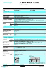
HV/LV distribution <strong>transformers</strong>TRIHAL <strong>cast</strong> <strong>resin</strong> <strong>transformers</strong>160 to 3150 kVAinsulation level 24 kV - low voltage 400 VISO 9001AFAQ N 1990/113bdescriptionThis range comprises <strong>transformers</strong> in accordancewith the following specifications: 50 Hz three-phase <strong>transformers</strong> for indoorinstallation (outdoor installation or otherfrequency on request); <strong>cast</strong> <strong>resin</strong> <strong>dry</strong> <strong>type</strong>; thermal class F; ambient 40°C, altitude 1000m (1) ; natural air cooling <strong>type</strong> AN; LV winding usually made of aluminium sheet(insulated strip for low ratings). The core and LVwindings assembly is given an additionalprotective coating of alkyd <strong>resin</strong>; HV winding manufactured from insulatedround wire or rectangular strip; HV winding is vacuum <strong>cast</strong> in epoxy<strong>resin</strong> (2) efficiently fireproofed with trihydratedalumina;TRIHAL <strong>transformers</strong> can be supplied: without enclosure (IP00).The installer must ensure that access to the livecore and windings is prevented (3) ; with IP31 metal enclosure.It prevents direct contact with live components.standardsThese <strong>transformers</strong> are in accordance withstandards: IEC 76-1 à 76-5; IEC 726 (1982); CENELEC (European Committee for Electrotechnicalstandardization) harmonizationdocuments HD 538-1 S1:1992 and HD 464 S1:1988 / A2: 1991 /A3:1992 concerning <strong>dry</strong> <strong>type</strong><strong>transformers</strong>.standard equipmentTRIHAL without enclosure (IP00): 4 flat bi-directional rollers; 4 lifting holes; haulage holes on the underbase; 2 earthing points; 1 rating plate (on HV side); 1 warning label“electricity danger”; HV voltage variation by off circuit tappinglinks; HV connection bars for connection fromabove;LV pre-drilled terminations on above; 1 routine test certificate and 1 instructionleaflet for installation commissioning andmaintenance;TRIHAL with IP31 metal enclosure: TRIHAL without enclosure (IP00) as above; IP31 integral metal enclosure (except thebottom: IP21): with standard anti corrosion protection; lifting lugs for transformer and enclosureassembly; access to tappings on the HV side byremoving a bolted panel which is fitted withhandles, warning label, rating plate and avisible braid for earthing; blanked off holes provided for fitting RonisELP1 or alternatively Profalux P1 locks on theHV tapping access panel; 2 gland plates, one on the HV and one on theLV side. These may be removed and drilled totake cable glands which are not supplied; 1 flap door in the base on the HV side topermit HV cable entry. Connection made to topof delta bars.optionsThe following fittings can be provide: 1 thermal protection module comprising6 PTC thermostatic sensors (2 per phase)connected to a terminal board with a plug-inconnector and an electronic converter with 2contacts (alarm 1 and alarm 2) suppliedseparately; 3 HV plug-in connectors (HN 52 S 61) maybe used as follows: fixed on a mounting plate from the uppercore clamp (TRIHAL IP00); fixed on top of the transformer enclosure onthe HV side (TRIHAL IP 31); straight or elbow connectors can also besupplied. Please state cable characteristics; additional LV terminal plates (tinned copper); 1 locking device to secure plug-in bushings(without lock and indiscriminitely suitable for aRonis EPL11AP, ELP1, ELP2 or Profalux P1,P2, V1, V21 lock mounting); forced cooling by fans to give an AF ratingof 140%.Nota: These options are those usuallyspecified and many alternatives can beprovided on request.250 kVA (IP00) 20 kV/400 V +400 kVA (IP31) 20 kV/400 VLV pre-drilled terminations630 kVA - 20 kV/400 V(1) Please state when ambient > 40°C or altitude > 1000 m.(2) a <strong>cast</strong>ing system developped and patented by FranceTransfo.(3) when the transformer is energized, the winding <strong>resin</strong> coatingand the heat shrinkable protection of the HV connectionbars do not ensure any protection against touch.
HV/LV distribution <strong>transformers</strong>TRIHAL <strong>cast</strong> <strong>resin</strong> <strong>transformers</strong>160 to 3150 kVAinsulation level 24 kV - low voltage 400 Velectrical characteristicsinsulation level: 7.2 kV and 12 kVrated power (kVA) (1) ( * ) 160 (2) 250 315 (2) 400 500 (2) 630 800 1000 1250 1600 2000 2500 3150rated primary voltage (1)5 to 12 kV (dual voltage on request)rated insulation level (3)7.2 kV for 5.5 kV - 12 kV for 10 kVfrequency (1)50 Hzmaximum ambient temperature 40°Csecondary voltage at no load (1) 400 V between phases, 231 V phase to neutralHV tapping range (off-circuit) (1) ± 2.5 %vector groupDyn 11 or Dyn 5 (delta, star neutral brought out)losses no-load losses 610 820 950 1150 1300 1500 1700 2000 2500 2800 3500 4300 5500(W) at 75°C 2300 3100 3600 4300 5200 6400 7700 8800 10500 12300 14900 18300 22000load losses at 120°C 2700 3500 4100 4900 6000 7300 8800 10000 12000 14000 17000 21000 25000rated impedance voltage (%) 4 4 4 4 4 4 6 6 6 6 6 6 7no-load current (%) 2.3 2. 1.8 1.5 1.5 1.3 1.3 1.2 1.2 1.2 1.1 1 1switching current Ie/In (peak value) 13.5 13 13 13 13 12 9 9 9 9 9.5 8.5 8.5time constant 0.13 0.18 0.20 0.25 0.25 0.26 0.30 0.34 0.35 0.42 0.4 0.5 0.6noise level (4) acoustic power LWA 62 65 67 68 69 70 72 73 75 76 77 81 81dB(A) acoustic pressure LPA at 1 metre 50 53 55 55 56 57 59 59 61 61 61 65 65insulation level: 17.5 kV and 24 kVrated power (kVA) (1) ( * ) 160 (2) 250 315 (2) 400 500 (2) 630 800 1000 1250 1600 2000 2500 3150rated primary voltage (1)20 kVrated insulation level (3)24 kVfrequency (1)50 Hzmaximum ambient temperature 40°Csecondary voltage at no load (1) 400 VHV tapping range (off-circuit) (1) ± 2.5 %vector groupDyn 11 (delta, star neutral brought out)losses no load losses 650 880 1030 1200 1400 1650 2000 2300 2800 3100 4000 5000 6300(W) at 75°C 2300 3300 4000 4800 5700 6800 8200 9600 11500 14000 17500 20000 23000load losses at 120°C 2700 3800 4600 5500 6500 7800 9400 11000 13100 16000 20000 23000 26000rated impedance voltage (%) 6 6 6 6 6 6 6 6 6 6 6 6 7no-load current (%) 2.3 2 1.8 1.5 1.5 1.3 1.3 1.2 1.2 1.2 1.1 1 1switching current Ie/In (peak value) 10.5 10.5 10 10 10 10 10 10 10 10 9.5 9.5 9.5time constant 0.13 0.18 0.20 0.25 0.25 0.26 0.30 0.30 0.35 0.4 0.4 0.5 0.6noise level (4) acoustic power LWA 62 65 67 68 69 70 72 73 75 76 78 81 81dB(A) acoustic pressure LPA at 1 metre 50 53 55 56 56 57 59 59 61 62 63 66 65( ) the rated power is defined by natural air cooling (AN).*Should there be particular constraints, it may be increased by40% by forced cooling addition (AF). Please consult us.(1) other possibilities upon request, consult us.(2) non standard ratings available on request.(3) reminder of insulation levels:rated insulationlevel (kV)7.2 12 17.5 24kV r.m.s. 50 Hz - 1 mn 20 28 38 50kV B.I.L. 1.2/50 µs 60 75 95 125(4) according to CEI 551
Groupe Merlin Gerin · Usine d’Ennery (Moselle) FranceHV/LV distribution <strong>transformers</strong>TRIHAL <strong>cast</strong> <strong>resin</strong> <strong>transformers</strong>160 to 3150 kVAinsulation level 24 kV - low voltage 400 VØ 13E/2J J LIdimensions and weightsTRIHAL <strong>transformers</strong> withoutenclosure housing (IP00)7.2 to 24 kV / 400 VtappinglinksCMHDimensions and weights indicated in the tablebelow are provided as an example for primarysingle voltage <strong>transformers</strong> 7.2 to 24kV / 400V.They apply to <strong>transformers</strong> with electricalcharacteristics shown in the previous table.For other voltages, impedance voltages anddual-voltages, weights and dimensions aredifferent (consult us).BearthingterminalØ 125 (200)DA40 (70)DEIn brackets, dimensions from 1000 up to 3150 kVA.insulation level: 7.2 kV and 12 kV - low voltage 400 Vrated power (kVA) (1) ( * ) 160 250 315 400 500 630 800 1000 1250 1600 2000 2500 3150dimensions (mm) A 990 1070 1160 1230 1260 1340 1380 1520 1590 1710 1900 2150 2200B 665 680 795 795 795 800 810 945 945 945 1195 1195 1195C 1330 1370 1410 1400 1600 1630 1610 1670 1830 1940 2250 2350 2600D 520 520 670 670 670 670 670 820 820 820 1070 1070 1070E 650 650 800 800 800 800 800 950 950 950 1200 1200 1200H 170 160 210 200 200 180 180 230 220 200 230 230 300I 350 360 380 390 390 410 410 430 440 460 460 470 460J 330 360 390 410 420 450 460 500 530 570 630 640 690L 200 210 230 230 240 250 260 280 280 250 280 280 380M 860 900 940 920 1050 1070 1110 1180 1440 1540 1700 1750 1750weights (kg) 770 950 1150 1360 1580 1820 1880 2360 2710 3400 4800 5800 7300insulation level: 17.5 kV and 24 kV - low voltage 400 Vrated power (kVA) (1) ( * ) 160 250 315 400 500 630 800 1000 1250 1600 2000 2500 3150dimensions (mm) A 1070 1140 1170 1230 1300 1340 1400 1560 1610 1700 1950 2030 2200B 680 690 795 795 795 800 805 945 945 945 1195 1195 1195C 1320 1350 1510 1490 1580 1690 1720 1920 2030 2170 2380 2440 2600D 520 520 670 670 670 670 670 820 820 820 1070 1070 1070E 650 650 800 800 800 800 800 950 950 950 1200 1200 1200H 160 150 220 210 190 190 180 230 220 210 290 290 300I 360 370 370 380 400 400 410 430 440 460 450 460 460J 360 380 390 410 440 450 470 510 530 560 630 640 690L 180 180 190 200 210 210 220 250 250 260 310 320 380M 890 930 1090 1070 1110 1210 1240 1410 1510 1650 1770 1750 1750weights (kg) 780 950 1140 1290 1520 1730 1990 2480 2810 3430 4720 5980 7300
nº 217840Groupe Merlin Gerin · Usine d’Ennery (Moselle) FranceHV/LV distribution <strong>transformers</strong>TRIHAL <strong>cast</strong> <strong>resin</strong> <strong>transformers</strong>160 to 3150 kVAinsulation level 24 kV - low voltage 400 VØ 13Idimensions and weightsTRIHAL <strong>transformers</strong> with IP31metal enclosure7.2 to 24 kV / 400 VtappinglinksCDimensions and weights indicated in the tablebelow are provided as an example for primarysingle voltage <strong>transformers</strong> 7.2 to 24kV / 400V.They apply to <strong>transformers</strong> with electricalcharacteristics shown in the previous table.For other voltages, impedance voltages anddual-voltages, weights and dimensions aredifferent (consult us).earthingterminalØ 125 (200)DA40 (70)DBIn brackets, dimensions from 1000 up to 3150 kVA.insulation level 12 kV - low voltage 400 Vrated power (kVA) (1) ( * ) 160 250 315 400 500 630 800 1000 1250 1600 2000 2500 3150dimensions (mm) A 1390 1480 1530 1550 1570 1620 1650 1880 1820 2080 2200 2550 2450B 875 895 920 945 955 975 935 1020 1020 1040 1300 1300 1350C 1680 1750 1760 1780 1840 2000 1920 2050 2150 2360 2850 3000 2900D 520 520 670 670 670 670 670 820 820 820 1070 1070 1070I 520 530 550 560 560 580 580 650 630 640 700 710 850weights (kg) 960 1150 1360 1580 1810 2060 2120 2620 2990 3750 5340 6340 7900insulation level 24 kV - low voltage 400 Vrated power (kVA) (1) ( * ) 160 250 315 400 500 630 800 1000 1250 1600 2000 2500 3150dimensions (mm) A 1380 1430 1530 1530 1540 1560 1600 1710 1760 1860 2100 2120 2450B 850 865 875 890 910 920 935 1020 1020 1030 1265 1265 1350C 1560 1590 1750 1730 1820 1930 1960 2160 2270 2410 2660 2710 2900D 520 520 670 670 670 670 670 820 820 820 1070 1070 1070I 530 540 550 560 570 570 580 650 640 630 710 820 850weights (kg) 960 1140 1340 1500 1740 1960 2230 2740 3080 3760 5200 6510 7900
<strong>Trihal</strong> <strong>cast</strong> <strong>resin</strong> <strong>transformers</strong>Basic technical specification Poland n° ST-Tri- PL-gb-1aPublishing : 29/06/1998Application: Industry and tertiary Customers: AllStandards: IEC 76, 726 - HD 538Technical data sheet reference:NoInstallation:IndoorCooling:ANFrequency:50 HzThermal class:FMaximal ambient temperature : 40°C Daily average: 30 °C yearly average: 20°CMaximal temperature of the insulation system: 155°CWindings temperature rise:100 KMaximal altitude:1000mVector group: Dyn 11 ou Dyn 5Windings materialAluminiumHV terminations:LV terminations:Standard accessories :(included in basic price)on HV pre-drilled terminations from the topon LV pre-drilled terminations from the topThermal protection (6 PTC + Z electronic converter)rating plate in english, warning label "electricity danger"4 flat bi-directional rollersP (kVA) pitch (mm) ∅ (mm) width (mm)100 à 250 520 125 40315 à 800 670 125 401000 à 1600 820 200 702000 à 3150 1070 200 702 earthing points without enclosure and 1 earthing point with enclosureInstallation 215000 FT in english (ref-GEa215000)Additional characteristics: Terminals marking according to IEC 76(1U,1V,1W,2U,2V,2W,2N)Additional accessories and options : - Enclosure IP 31(extra cost)- Antivibration pads- Copper windingsRated primary voltage: 15 or 15.75 kV - Rated insulation: 17.5 kV (95/38)20 or 21 - Rated insulation: 24 kV (125/50)Off circuit tapping links : ±2.5 %± 5 %Secondary voltage ( at no load ):400 VPowerNo loadlossesLoadlossesat 120°CLoadlossesat 75°CUcc Lwa Lpaat1mIP 00 IP 31Length Width Height TotalWeightLength Width Height TotalWeightkVA W W W % dBA dBA mm mm mm kg mm mm mm kg100 460 2100 1800 6 59 47 1050 670 1300 690 1430 835 1570 870160 650 2900 2500 6 62 50 1080 680 1310 790 1530 845 1580 980250 880 3800 3300 6 65 53 1160 690 1390 1000 1540 875 1750 1200400 1200 5500 4600 6 68 55 1240 795 1490 1290 1550 890 1760 1500630 1650 7800 6800 6 70 56 1380 805 1700 1760 1650 925 1980 2000800 2000 9400 8200 6 72 58 1430 810 1750 2050 1880 945 2060 23101000 2300 11000 9600 6 73 59 1560 945 1880 2480 1880 1020 2200 27601250 2800 13200 11500 6 75 61 1710 945 1910 3020 2080 1025 2350 33201600 3100 16000 14000 6 76 61 1700 945 2130 3470 2080 1025 2540 38402000 3900 19000 16600 6 77 62 1900 1195 2170 4550 2130 1255 2640 50102500 5000 23000 20000 6 81 65 2050 1195 2400 5400 2450 1270 3000 5940Tolerances : according to IEC 76Approximate dimensions. Only the drawings will commit France TransfoMKT/RLB - TRI POLA.DOC - 12/10/98 page1/2 FRANCE TRANSFO
<strong>Trihal</strong> <strong>cast</strong> <strong>resin</strong> <strong>transformers</strong>Basic technical specification Poland n° ST-Tri- PL-gb-2aPublishing : 29/06/1998Application: Industry and tertiary Customers: AllStandards: IEC 76, 726 - HD 538Technical data sheet reference:NoInstallation:IndoorCooling:ANFrequency:50 HzThermal class:FMaximal ambient temperature : 40°C Daily average: 30 °C yearly average: 20°CMaximal temperature of the insulation system: 155°CWindings temperature rise:100 KMaximal altitude:1000mVector group: Dyn 11 or Dyn 5Windings materialAluminiumHV terminations:LV terminations:Standard accessories :(included in basic price)on HV pre-drilled terminations from the topon LV pre-drilled terminations from the topThermal protection (6 PTC + Z electronic converter)rating plate in english, warning label "electricity danger"4 flat bi-directional rollersP (kVA) pitch (mm) ∅ (mm) width (mm)100 à 250 520 125 40315 à 800 670 125 401000 à 1600 820 200 702000 à 3150 1070 200 702 earthing points without enclosure and 1 earthing point with enclosureInstallation 215000 FT in english (ref-GEa215000)Additional characteristics: Terminals marking according to IEC 76(1U,1V,1W,2U,2V,2W,2N)Additional accessories and options : - Enclosure IP 31(extra cost)- Antivibration pads- Copper windingsRated primary voltage: 6 kV - Rated insulation: 7.2 kV (60/20)Off circuit tapping links : ±2.5 %± 5 %Secondary voltage ( at no load ):400 VPowerNo loadlossesLoadlossesat 120°CLoadlossesat 75°CUcc Lwa Lpaat1mIP 00 IP 31Length Width Height TotalWeightLength Width Height TotalWeightkVA W W W % dBA dBA mm mm mm kg mm mm mm kg100 440 2000 1700 4 59 47 940 660 1300 650 1360 855 1570 830160 610 2700 2300 4 62 50 990 665 1330 770 1390 875 1680 960250 820 3500 3100 4 65 53 1070 680 1370 950 1480 895 1750 1150400 1000 5200 4500 6 68 56 1260 795 1330 1220 1570 905 1760 1440630 1370 7600 6700 6 70 57 1320 795 1560 1630 1610 920 1980 1870800 1700 8800 7700 6 72 59 1380 810 1610 1880 1650 935 1920 21201000 2000 10000 8800 6 73 59 1520 945 1670 2360 1880 1020 2050 26201250 2500 12000 10500 6 75 61 1590 945 1830 2710 1820 1020 2150 29901600 2800 14000 12300 6 76 62 1710 945 1940 3400 2080 1040 2360 37502000 3800 17000 14900 6 77 62 1900 1195 2250 4800 2200 1300 2850 53402500 4300 21000 18300 6 81 65 2150 1195 2350 5800 2550 1300 3000 6340Tolerances : according to IEC 76Approximate dimensions. Only the drawings will commit France TransfoMKT/RLB - TRI POLA.DOC - 12/10/98 page2/2 FRANCE TRANSFO
<strong>Trihal</strong> <strong>cast</strong> <strong>resin</strong> <strong>transformers</strong>Basic technical specification Czech Republic n° ST-Tri-CZ-gb-5bPublishing : 18/06/1998Application: Industry and tertiary Customers: AllStandards:IEC 76, 726, DIN 42523 - Normal lossesTechnical data sheet reference:NoInstallation:IndoorCooling:ANFrequency:50 HzThermal class:FMaximal ambient temperature : 40°C Daily average: 30 °C yearly average: 20°CMaximal temperature of the insulation system: 155°CWindings temperature rise:100 KMaximal altitude:1000mVector group: Dyn 11 or Dyn 5 or Dyn 1Windings materialFT’s choiceHV terminations:on HV pre-drilled terminations from the topLV terminations:on LV pre-drilled terminations from the topStandard accessories:(Included in basic price)Additional characteristics:Thermal protection (2 PTC per phase + Z electronic converter)rating plate , warning label "electricity danger"4 flat bi-directional rollers:P (kVA) pitch (mm) ∅ (mm) width (mm)100 à 250 520 125 40315 à 800 670 125 401000 à 1600 820 200 702000 à 3150 1070 200 702 earthing pointsInstallation 215000 FT in english (ref-GEa215000)Terminals marking(1U,1V,1W,2U,2V,2W,2N)Additional accessories and options : - Enclosure IP 31(extra cost) - 3 PT100 sensors + TEC 935- Dial <strong>type</strong> thermometer with maxima pointer :without contact or 2 contacts- 3 fixed HV plug-in bushings - 36 kV - 400 A for IP00 or IP31- 3 mobile HV plug-in connectors - 36 kV - 400 A- Antivibration pads- Copper windings- LV terminations from below or on the small side of the enclosure- Option LV = 500 to 1000 V - rated insulation : 1.1 kV- Option rated insulation : 38.5 kV (190/75 kV)(discount)- Thermal protection (2 PTC per phase + Z electronic converter)Rated primary voltage: 35 kV - Rated insulation: 36 kV (170/70) Normal lossesOff circuit tapping links : ± 2.5% ± 5 %Secondary voltage ( at no load ):400 or 420 VIP 00 IP 31Power No loadlossesLoad lossesat 75°CUcc Lwa Lpaat 1mLength Width Height TotalWeightLength Width Height TotalWeightkVA W W % dBA dBA mm mm mm kg mm mm mm kg100 660 1900 6 59 46 1380 825 1580 1170 1750 1270 1920 1450160 960 2500 6 62 49 1400 905 1750 1380 1770 1280 2030 1680250 1280 3500 6 65 52 1400 905 1750 1570 1770 1280 2030 1870315 1450 4300 6 67 54 1450 910 1800 1750 1800 1290 2060 2050400 1650 5000 6 68 59 1470 915 1820 1900 1840 1305 2060 2210630 2200 7000 6 70 60 1620 940 2040 2530 1930 1190 2280 2840800 2650 8500 6 72 62 1700 950 2110 2890 1980 1205 2340 32001000 3100 10000 6 73 63 1700 950 2110 3030 1980 1205 2340 33601250 3600 12100 6 75 60 1810 1000 2170 3900 2150 1230 2400 34501600 4200 14900 6 76 61 1920 1065 2240 4340 2290 1285 2470 48002000 5000 18300 6 78 63 2180 1225 2390 5140 2500 1380 2470 58002500 5800 21800 6 81 65 2450 1250 2400 6900 2750 1500 2500 7600Load losses at 120°C = Load losses at 75°C x 1.14Approximate dimensions. Only the drawings will commit France TransfoMKT/RLB - TRI CZEC.DOC - 12/10/98 page5/5 FRANCE TRANSFO
THE INFLUENCE OF HARMONICS ON DIMEN-SIONING OFTRANSFORMERSList of contents :1.Harmonic waves2.Harmonic generators and their influences3.The effects of harmonics on a transformer’s behaviour4.Remedies5. Dimensioning the transformer6. ConclusionsF:Dcial/MK/MKT/InfoMK/Anglais/GENERAL/TIGEA09 1
1. Harmonic wavesIn electrical networks the real current wave-form is often different from the pure sinewave that characterises alternating current.The wave-form is modified by other waves, which are also sinusoidal but whosefrequency is an integer multiple of the fundamental frequency, being superposedon the fundamental wave of frequency 50 Hz.These other waves are called harmonic waves or simply harmonics.Fig.1 - Waves modified by harmonicsThese harmonics are defined by :• the sinusoidal wave at the base frequency or so called fundamental component•F1 = 50 Hz• the coefficient giving the frequency (integer multiple of the fundamental component)or the so called harmonic number :Hi = Fh / F1• the harmonic factor defining the ratio of its intensity to the intensity of the fundamentalcomponent :Ti (%) = Ih / I1F:Dcial/MK/MKT/InfoMK/Anglais/GENERAL/TIGEA09 2
2. Harmonic generators and their influencesThese days, power electronics are becoming increasingly used in industry andthis constitutes the main source of harmonic "pollution".The main harmonic generators are :• UPS inverters : supplying computers and other sensitive equipments• rectifier units : "alternating - direct" static converter• speed controllers : controlling electric motors• equipment using thyristors• ovens : arc or induction heatingComposition of current emitted by a converterin "fundamental current" and"harmonic currents"I L Total current (apparent wave-form)I 1 Fundamental current at 50 HzI 5 5th harmonic currentI 7 7th harmonic currentU ph Supply voltageThese harmonic generators change the electrical quality of the network by giving :• a higher true r.m.s. intensity• a higher peak intensity• higher frequenciesand will cause certain interference effects :the resulting value of true r.m.s. current is greater than the calculated current valuesfor the required power, which leads to a risk of premature ageing of theequipment.• resonance phenomena can occur at certain frequencies, leading to dangerousovervoltages and overcurrents.F:Dcial/MK/MKT/InfoMK/Anglais/GENERAL/TIGEA09 3
3. The effects of harmonics on a transformer’s behaviourA transformer is defined by its ratedpower which is equal to the productof no load voltage and the ratedcurrent (times √3 for three-phase)and is calculated as a function of thenetwork frequency.However, as we have seen in theprevious chapter, a harmonic generatorsignificantly changes the transformer’sdimensioning characteristics:• Ohmic lossesif no account is taken of harmoniccurrents, the power that the <strong>transformers</strong>hould deliver will be greaterthan its rated power, leading to anincrease in Ohmic losses (RI 2 ) andtherefore to a risk of deteriorating thedielectric qualities of the transformerdue to over-heating.• Eddy current lossesEddy currents are proportional to the square of the frequency. However, a harmoniccurrent is of high frequency and could thus, even with a low factor, causeadditional losses which can not be ignored.• the magnetic corein extreme cases, two phenomena can disrupt the correct operation of a transformer:⇒ at high frequency harmonic currents there are corresponding harmonic fluxeswhich are superposed on the fundamental flux. Depending on the upstream impedance,these fluxes can increase the resulting peak flux value.⇒ a possible continuous component will create a shift in the hysteresis cyclerelative to zero. For half a cycle, the magnetic core is subjected to a flux whichis too high.These two cases can result in the induction level reaching the saturation peakfor the magnetic core, in an increase in the ferromagnetic losses of magnetis-F:Dcial/MK/MKT/InfoMK/Anglais/GENERAL/TIGEA09 4
ing current, and in addition, can make the transformer itself generate harmonics.4. RemediesThe existence of harmonic currents and their consequences in an electrical networkoutlined above makes it necessary to :• quantify the pollution level by calculation or by measuring harmonic currentsand voltages.• eliminate any risk of resonance within the range of harmonics encountered byseeking the lowest possible ratio (technical-economic) between capacitor powerand the supply’s short circuit power.• attenuate harmonic pollution⇒ separating pieces of equipment from one another by assigning a transformerto each of them (attenuating interference since the impedance ofthis part of the network is lower than that of a global supply).⇒ installing harmonic filters :series filter (also called resonance filter or high-pass)parallel filter (also called a stop filter or low-pass).• oversize the equipmentin spite of the above measures it is essential that equipment⇒ can withstand overloading due to any harmonics which may be present⇒ tolerates the nuisance with minimum effect.F:Dcial/MK/MKT/InfoMK/Anglais/GENERAL/TIGEA09 5
5. Dimensioning the transformer• To prevent the windings overheating :☞ The first solutioninvolves oversizing the transformer or limiting its load if it is a piece of equipmentwhich is already installed.Standards organisations UTE, CENELEC, ...) have adopted or are currently studyingderating equations such as :K = [1 + 0,1 * (Ì Hi 1,6 * Ti 2 )] -0,5See chapter 1 Hi = harmonic numberTi = harmonic factor expressed as a % of the transformer’srated intensi ty• Example 1A 1000 kVA transformer delivers a current which includes the following harmonics :H5 = 25 % H7 = 14 % H11 = 9 % H13 = 8 %K = [1 + 0,1 * (5 1,6 * 0,25 2 + 7 1,6 * 0,14 2 + ...)] -0,5The calculation gives k = 0,91 : the transformer will only supply 910 kVA.• Exemple 2We want to determine the size of a transformer needed to supply 1000 kVA withharmonics of number H = 6 x n Ù 1, with n = 1,2, ...etc and with a factor of 1/H(typical case of a six-phase rectifier).By limiting the calculation to number 29, the coefficient K will be 0,87.K = [1 + 0,1 * (5 1,6 *0,2 2 + 7 1,6 * 0,14 2 + 11 1,6 * 0,09 2 ...)] -0,5The minimum power for the transformer becomes 1000 / 0,87 = 1150 kVAF:Dcial/MK/MKT/InfoMK/Anglais/GENERAL/TIGEA09 6
☞ The second solutionThis involves dimensioning of a transformer which is specially adapted to supplya harmonic generator, subject to prior agreement between the user and the manufacturer.• Against saturation of the magnetic core :when the extreme conditions described in § 3 are specified, it may be necessaryto :⇒ specify a transformer operating with a low-flux density to account for the highharmonic flux.⇒ specify a gapped magnetic core to limit the influence of any possible continuouscomponent.6. ConclusionsWhatever the configuration and the solution chosen, it is essential that there isdialogue between the user and the manufacturer.This concise analysis of the influence of harmonic waves shows that the problemis complex :• the consequences on elements of the network due to the overloads and overvoltageswhich the harmonics produce can be dangerous.• attention must be paid to controlling and attenuating harmonic interferenceeffects.• the influence of harmonics makes it necessary to increase the size of equipmentand results in a large increase in cost (up to 50 % in extreme cases).BibliographyEDFMerlin GerinLes Cahiers de l'Ingénierie (Engineering Manuals)Qualité de l'alimentation électrique (Quality of electrical supply)Cahiers techniquesF:Dcial/MK/MKT/InfoMK/Anglais/GENERAL/TIGEA09 7