Sepam - HV/MV Protection and control units (ENG) - Trinet
Sepam - HV/MV Protection and control units (ENG) - Trinet
Sepam - HV/MV Protection and control units (ENG) - Trinet

Create successful ePaper yourself
Turn your PDF publications into a flip-book with our unique Google optimized e-Paper software.
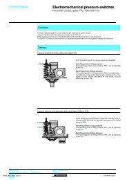
<strong>Protection</strong><br />
<strong>and</strong> <strong>control</strong><br />
<strong>Sepam</strong> range<br />
<strong>Sepam</strong> 2000<br />
Motor
Presentation<br />
Contents<br />
page<br />
presentation 2<br />
selection table 3<br />
metering 4<br />
protection 6<br />
<strong>control</strong> <strong>and</strong> monitoring 8<br />
functional <strong>and</strong> connection schemes 11<br />
other connection schemes 17<br />
examples of connections 19<br />
communication 20<br />
characteristics 21<br />
installation 22<br />
ordering information 24<br />
Motor protection <strong>and</strong> <strong>control</strong> consists of performing<br />
the metering, protection, <strong>control</strong> <strong>and</strong> monitoring<br />
functions required for operation.<br />
<strong>Sepam</strong> 2000 provides all these functions globally.<br />
All the equipment <strong>and</strong> mechanisms that are generally<br />
found in a <strong>MV</strong> cubicle <strong>control</strong> cabinet are replaced<br />
by a single device which performs:<br />
c protection,<br />
c metering,<br />
c <strong>control</strong> <strong>and</strong> monitoring using protection functions<br />
<strong>and</strong> logic inputs to activate the trip outputs, closing<br />
outputs, etc. <strong>and</strong> annunciation.<br />
Advantages<br />
c Indication of phase <strong>and</strong> earth fault current values at the time of breaking provides<br />
the operator with useful assistance in determining the causes <strong>and</strong> seriousness<br />
of the fault,<br />
c The high level of electromagnetic compatibility (EMC) makes it possible to use<br />
advanced digital technology functions in electrical substations, without the need<br />
for any particular precautions,<br />
c <strong>Sepam</strong> 2000's continuous self-testing sets the device in a predetermined failsafe<br />
position whenever a failure occurs, thereby preventing r<strong>and</strong>om operation,<br />
c Terminals that are individually disconnectable while energized allow easy<br />
maintenance,<br />
The optional communication function can be used for remote setting, remote<br />
metering, remote annunciation <strong>and</strong> remote <strong>control</strong> via a 2 wire link with a remote<br />
<strong>control</strong> <strong>and</strong> monotoring system for centralised operations.<br />
c Setting <strong>and</strong> testing are extremely simple:<br />
v the settings may be made on the front panel (serial link):<br />
- one by one, using the TSM2001 pocket terminal, or the SFT2801 PC software<br />
program,<br />
- all at once using the SFT2821 PC software program (downloading),<br />
v a direct readout is given for primary current <strong>and</strong> voltage <strong>and</strong> for the metering<br />
function, simple testing by injection guarantees the coherency of all settings.<br />
c Each <strong>Sepam</strong> 2000 is designed to meet all the application needs <strong>and</strong> includes all<br />
the necessary functions ready for use (protection functions, metering, <strong>control</strong> logic<br />
<strong>and</strong> communication).<br />
The <strong>control</strong> logic may be adapted to most usuals schemes by a simple<br />
parametring. This allows a better safety <strong>and</strong> optimization of wiring.<br />
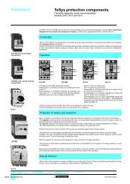
<strong>Sepam</strong> 2000<br />
Compact S26.<br />
<strong>Sepam</strong> 2000<br />
St<strong>and</strong>ard S36.<br />
The wide setting ranges provide for the most widely varied cases.<br />
Installation in the switchboard is simplified:<br />
c just one device to install, the <strong>Sepam</strong> 2000. It comes in two models<br />
with different widths:<br />
v st<strong>and</strong>ard S36,<br />
v compact S26 (for certain types).<br />
c cabling is limited to:<br />
v st<strong>and</strong>ard 1A or 5A current transformers or linear CSP sensors (Rogowski coil<br />
principle),<br />
v voltage transformers,<br />
v temperature probes (RTDs),<br />
v <strong>control</strong> <strong>and</strong> annunciation <strong>units</strong> (start/stop pushbutton, device position, etc),<br />
v actuators (trip <strong>and</strong> closing coils).<br />
Customization (1)<br />
(1)<br />
Please refer to document<br />
<strong>Sepam</strong> 2000 customized application.<br />
St<strong>and</strong>ard <strong>control</strong> <strong>and</strong> monitoring carried out in <strong>Sepam</strong> 2000's internal PLC can be<br />
customized. The number of inputs <strong>and</strong> outputs can be increased by adding<br />
extension boards (please contact us for further information).<br />
2 Motor
Selection table<br />
<strong>Sepam</strong> 2000 motors<br />
functions ANSI <strong>Sepam</strong> types (1)<br />
code M02 M03 M04 M05 M06 M07 M08 M09 M11 M14 M15 M16<br />
M20 M21 M22 M23<br />
protection<br />
thermal overload 49 1 1 1 1 1 1 1 1 1 1 1 1<br />
phase overcurrent 50/51 2 2 2 2 2 2 2 2 2 2 2 2<br />
earth fault (sensitive E/F) 50N/51N(G) 2 2 2 2 2 2 2 2 2 2 2 2<br />
negative sequence/unbalance 46 1 1 1 1 1 1 1 1 1 1 1 1<br />
locked rotor/excessive starting time 48/51LR 1 1 1 1 1 1 1 1 1 1 1 1<br />
phase undercurrent 37 1 1 1 1 1 1 1 1 1 1 1 1<br />
starts per hour 66 1 1 1 1 1 1 1 1 1 1 1 1<br />
positive sequence undervoltage 27D 2 2 2 2 2 2 2 2 2 2<br />
direction of rotation 47 1 1 1 1 1 1 1 1 1 1<br />
directional earth fault 67N 1 1 1 1<br />
reverse real power 32P 1 1 1<br />
reactive overpower 32Q/40 1 1 1<br />
temperature set points 38/49T 6 6 6 6 6 6 6<br />
12 12 12 12<br />
motor differential 87M 1 1 1 1<br />
metering<br />
phase currents (I1, I2, I3) c c c c c c c c c c c c<br />
peak dem<strong>and</strong> phase currents (I1, I2, I3) c c c c c c c c c c c c<br />
voltages (U21, U32, U13, V1, V2, V3) c c c c c c c c c c<br />
real / reactive power (P, Q) c c c c c c c c c c<br />
peak dem<strong>and</strong> real / reactive power c c c c c c c c c c<br />
power factor c c c c c c c c c c<br />
frequency c c c c c c c c c c<br />
accumulated real / reactive energy (±Wh, ±VArh) c c c c c c c c c c<br />
tripping currents (I1, I2, I3, Io) c c c c c c c c c c c c<br />
true rms current c c c c c c c c c c c c<br />
disturbance recording c c c c c c c c c c c c<br />
thermal capacity used c c c c c c c c c c c c<br />
start inhibit time delay / c c c c c c c c c c c c<br />
number of starts before inhibition<br />
temperature c c c c c c c<br />
phase rotation c c c c c c c c c c<br />
unbalance ratio / unbalance current c c c c c c c c c c c c<br />
starting time <strong>and</strong> current c c c c c c c c c c c c<br />
residual current c c c c c c c c c c c c<br />
residual voltage c c c c<br />
cumulative breaking current c c c c c c c c c c c c<br />
<strong>and</strong> number of breaks<br />
differential current <strong>and</strong> through current c c c c<br />
<strong>control</strong> <strong>and</strong> monitoring<br />
open / close c c c c c c c c c c c c<br />
lockout relay 86 c c c c c c c c c c c c<br />
inhibit closing 69 c c c c c c c c c c c c<br />
annunciation 30 c c c c c c c c c c c c<br />
load shedding c c c c c c c c c c c c<br />
restart c c c c c c c c c c<br />
logic discrimination 68 c c c c c c c c c c c c<br />
trip circuit supervision 74 c c c c c c c c c c c c<br />
detection of plugged 74 c c c c c c c c c c c c<br />
connectors (DPC)<br />
operation counter c c c c c c c c c c c c<br />
running hours counter c c c c c c c c c c c c<br />
phase fault trip counter c c c c c c c c c c c c<br />
disturb. recording triggering c c c c c c c c c c c c<br />
<strong>Sepam</strong> models<br />
st<strong>and</strong>ard S36 YR XR XR ZR LR LS LS SR SR LS XR SR<br />
SS SS SS SS<br />
compact S26 LX LT LT LS (2) LT<br />
number of st<strong>and</strong>ard ESTOR boards 1 1 1 1 1 1 1 1 1 1 1 1<br />
The figures in the columns represent the number of similar protection devices.<br />
Example: for phase overcurrent protection, “2” means 2 separate phase overcurrent protection devices.<br />
(1)<br />
for motor transformers, please consult us.<br />
(2)<br />
except for M20.<br />
Motor<br />
3
Metering<br />
<strong>Sepam</strong> 2000 is an accurate metering device.<br />
It gives a direct readout of values, together<br />
with the related <strong>units</strong>, A, V, W...<br />
All the values needed for operation <strong>and</strong> used<br />
for commissioning are available locally <strong>and</strong> in<br />
the <strong>control</strong> room.<br />
Measurements needed for operation<br />
Currents<br />
Measurement of the current for each of the 3 phases of the circuit.<br />
Peak dem<strong>and</strong> currents<br />
Measurement of the greatest average current value on the 3 phases.<br />
The average current measurement is computed periodically (adjustable period: 5,<br />
10, 15, 30 or 60 minutes).<br />
The “clear” button is pressed for zero reset.<br />
Voltages<br />
Measurement of the circuit phase-to-phase <strong>and</strong> phase-to-neutral voltages.<br />
Real / reactive power<br />
Measurement of the real <strong>and</strong> reactive power, with the sign, in balanced<br />
<strong>and</strong> unbalanced 3-phase networks.<br />
Peak dem<strong>and</strong> real / reactive power<br />
Measurement of the greatest average real power (<strong>and</strong> reactive power) value,<br />
used to find the power absorbed during peak load periods. The average value<br />
is computed periodically (adjustable period: 5, 10, 15, 30 or 60 minutes).<br />
The “clear” button is pressed for zero reset.<br />
Measurements accessed on the front panel of <strong>Sepam</strong> 2000<br />
(serial link <strong>and</strong>/or display) <strong>and</strong> via the communication<br />
system.<br />
Power factor (p.f.)<br />
Measurement of the power factor, with the sign <strong>and</strong> type (capacitive or inductive),<br />
of the power absorbed.<br />
Frequency<br />
Measurement of frequency (based on positive sequence voltage or the U21 voltage<br />
input).<br />
Accumulated real / reactive energy<br />
The alphanumerical display unit shows the 4 accumulated real / reactive energy<br />
values:<br />
c real energy consumed,<br />
c reverse real energy,<br />
c reactive energy consumed,<br />
c reverse reactive energy.<br />
These values are saved in the event of a power failure.<br />
Tripping currents<br />
Measurements of the 3 phase currents <strong>and</strong> the residual current that were stored<br />
at the time that <strong>Sepam</strong> 2000 gave the tripping order. Used to find the fault current<br />
(fault analysis) <strong>and</strong> assess the level of wear of the breaker<br />
(maintenance assistance).<br />
The "clear" button is pressed for zero reset.<br />
True rms current<br />
Measurement of the rms value of phase 1 current up to 4 In, taking into account:<br />
c fundamental,<br />
c harmonics up to rank 21.<br />
Disturbance recording<br />
Recording of electrical signals <strong>and</strong> logical information before <strong>and</strong> after a fault<br />
recorder triggering order is given.<br />
Thermal capacity used<br />
Measurement of the relative thermal capacity used (with respect to the nominal<br />
thermal capacity) on account of the load.<br />
Start inhibit time delay / number of starts before inhibition<br />
According to the state of the "starts per hour" protection function, indication of:<br />
c the remaining time during which starting is inhibited,<br />
c the number of starts authorized before inhibition of starting.<br />
Temperature<br />
Temperature measurement in °C for each RTD.<br />
4 Motor
Measurements used<br />
for commissioning<br />
<strong>and</strong> maintenance<br />
Phase rotation<br />
Connection check, which gives the direction of phase<br />
rotation: “anticlockwise” or “clockwise”.<br />
Unbalance ratio / unbalance current<br />
Assistance in determining settings by giving<br />
the unbalance ratio measured as a percentage<br />
(negative sequence / absorbed current).<br />
Starting time <strong>and</strong> current<br />
Used to check the starting time <strong>and</strong> current to adjust<br />
overcurrent protection setting.<br />
Residual current / residual voltage<br />
Used to check the current <strong>and</strong> voltage sensor<br />
connections by giving the measurement of:<br />
c the residual current used for the earth fault<br />
protection function,<br />
c the residual voltage used for the directional earth<br />
fault protection function.<br />
Cumulative breaking current<br />
<strong>and</strong> number of breaks<br />
Used for breaking device maintenance.<br />
Differential current <strong>and</strong> through current<br />
Used to check the current sensor connections.<br />
Used to determine the cause of tripping.<br />
Example of the processing of a disturbance recording record<br />
using the SFT 2826 PC software program.<br />
Characteristics<br />
functions ranges accuracy (4)<br />
ammeter (1) 0 to 24 In ±0.5%<br />
peak dem<strong>and</strong> current (1) 0 to 24 In ±0.5%<br />
voltmeter (1) 0 to 1.5 Un ±0.5%<br />
wattmeter (1) 0 to 999 MW ±1%<br />
varmeter (1) 0 to 999 <strong>MV</strong>Ar ±1%<br />
peak dem<strong>and</strong> real power (1) 0 to 999 MW ±1%<br />
peak dem<strong>and</strong> reactive power (1) 0 to 999 <strong>MV</strong>Ar ±1%<br />
power factor (1) (3) -1 to +1 0.01<br />
frequency meter (1) 45 to 65 Hz ±0.02 Hz<br />
accumulated real energy (1) 0 to 280.10 6 MWh ±1%<br />
accumulated reactive energy (1) 0 to 280.10 6<br />
<strong>MV</strong>Arh ±1%<br />
tripping currents (1) phase: 0 to 24 In ±5%<br />
earth: 0 to 10 Ino ±5%<br />
true rms current (2) 0 to 4 In ±1%<br />
up to rank 21<br />
disturbance recording (5) record 86 periods 12 samples<br />
duration<br />
per period<br />
time before 1 to 85 periods<br />
triggering<br />
event<br />
thermal capacity used (6) 0 to 999% ±2%<br />
temperature (1) -50° to 250°C ±1°C<br />
phase rotation (2)<br />
anticlockwise, clockwise<br />
unbalance ratio (unbalance current) (2) 0 to 100% of Ib ±5%<br />
starting time (2) 0 to 999 s ±5%<br />
starting current (2) 0 to 24 In ±5%<br />
residual current (6) 0 to 10 Ino ±5%<br />
residual voltage (6) 0 to 1.5 Un ±5%<br />
cumulative breaking current (6) 0 to 9999 (kA) 2 +10%<br />
number of breaks (6) 0 to 99999<br />
differential current <strong>and</strong> through current (2) 0 to 24 In ±5%<br />
(1)<br />
measurement accessed on the front panel of <strong>Sepam</strong> 2000 (display <strong>and</strong> serial link) <strong>and</strong> via<br />
the communication system.<br />
(2)<br />
measurement accessed on the front panel of <strong>Sepam</strong> 2000 (serial link).<br />
(3)<br />
capacitive or inductive<br />
(4)<br />
typical accuracy with nominal values according to IEC 60255-6.<br />
(5)<br />
transfer of records to the front panel of <strong>Sepam</strong> 2000 using the SFT2801 software program<br />
<strong>and</strong> via Jbus/Modbus communication.<br />
(6)<br />
measurement accessed on front panel of <strong>Sepam</strong> 2000 (serial link) <strong>and</strong> via the<br />
communication system.<br />
Reminder:<br />
Rated current In, basis current Ib, rated voltage Un <strong>and</strong> current Ino are general parameters<br />
that are set at the time of <strong>Sepam</strong> 2000 commissioning.<br />
In is the current sensor rated current (CT rating).<br />
Ib is the current which corresponds to the motor power rating, adjustable from 0.4 to 1.3 In.<br />
Ino is the core balance CT current rating.<br />
Un is the phase-to-phase voltage of the voltage sensor primary windings.<br />
Motor<br />
5
<strong>Protection</strong><br />
Thermal overload (ANSI 49) F431*<br />
<strong>Protection</strong> of equipment against thermal damage<br />
caused by overloads. Thermal overload is calculated<br />
according to a mathematical model, with 2 time<br />
constants (T1 <strong>and</strong> T2), taking into account the effect<br />
of negative sequence current by means<br />
of an adjustable weighting coefficient.<br />
The function comprises:<br />
c an adjustable alarm setting,<br />
c an adjustable trip setting.<br />
Phase overcurrent (ANSI 50/51) F011, F012*<br />
Three-phase equipment protection against<br />
phase-to-phase (short-circuit) faults.<br />
The following types of time delay settings are<br />
available: definite, st<strong>and</strong>ard inverse, very inverse,<br />
extremely inverse or ultra inverse.<br />
Recommendations:<br />
c set higher than starting current,<br />
c instantaneous operation if the equipment<br />
is <strong>control</strong>led by a circuit breaker or contactor only.<br />
c time delayed operation if the equipment<br />
is <strong>control</strong>led by a contactor-fuse combination so that<br />
the fuse blows before the contactor when the fault<br />
current is greater than the contactor's breaking<br />
capacity.<br />
Earth fault (ANSI 50N/51N or 50G/51G) F081, F082*<br />
Connection <strong>and</strong> equipment earth fault protection.<br />
The following types of time delay settings are available:<br />
definite, st<strong>and</strong>ard inverse, very inverse, extremely<br />
inverse or ultra inverse.<br />
When earth fault current is detected by taking the<br />
sum of the 3 phase CTs, a harmonic 2 restraint is<br />
used to do away with transformer closing related<br />
tripping.<br />
Recommendations:<br />
c connection to special-purpose CSH core balance<br />
CT for greater sensitivity,<br />
c definite time operation.<br />
Negative sequence / unbalance (ANSI 46) F451*<br />
<strong>Protection</strong> of equipment against overheating caused<br />
by an unbalanced power supply, phase inversion or<br />
phase break, <strong>and</strong> against low levels of overcurrent<br />
between 2 phases.<br />
Recommendation:<br />
c use IDMT curves.<br />
Locked rotor / excessive starting time<br />
(ANSI 48/51LR) F441*<br />
<strong>Protection</strong> of motors that are liable to start<br />
with overloads or insufficient supply voltage<br />
<strong>and</strong>/or that drive loads that are liable to become<br />
locked (e.g. crusher).<br />
Locked rotor protection function is only confirmed<br />
after a time delay that corresponds to the normal<br />
starting time.<br />
Starts per hour (ANSI 66) F421*<br />
<strong>Protection</strong> against overheating caused by too frequent starts.<br />
Checking of:<br />
c the number of starts per hour,<br />
c the number of consecutive warm starts (detected by the thermal<br />
overload protection),<br />
c the number of consecutive cold starts.<br />
The protection inhibits motor energizing for a preset time period when the<br />
permissible limits are reached.<br />
Positive sequence undervoltage (ANSI 27D) F381, F382*<br />
<strong>Protection</strong> which prevents motor malfunctioning due to insufficient or unbalanced<br />
supply voltage.<br />
Direction of rotation (ANSI 47) F381*<br />
<strong>Protection</strong> which prevents the changing of direction of motor rotation following<br />
a power supply modification.<br />
Directional earth fault (ANSI 67N) F501*<br />
Highly sensitive earth fault protection for motor feeders supplied by long cables<br />
characterized by high capacitive current.<br />
Reverse real power (ANSI 32P)<br />
<strong>Protection</strong> of a synchronous motor against operation as a generator when driven<br />
by its load.<br />
It is based on the "real overpower" F531* function.<br />
Reactive overpower (ANSI 32Q/40) F541*<br />
<strong>Protection</strong> of a synchronous motor against field loss which causes<br />
overconsumption of reactive power <strong>and</strong> leads to the loss of synchronism.<br />
Temperature monitoring (RTDs) (ANSI 38/49T) F461...F466, F471...F476*<br />
<strong>Protection</strong> which detects abnormal overheating of motors (bearings <strong>and</strong>/or<br />
windings) equipped with Pt 100 type platinum resistive temperature devices:<br />
c 1 alarm setting,<br />
c 1 tripping setting.<br />
The RTD cabling is continuously monitored.<br />
Motor differential (ANSI 87M) F621*<br />
Fast, sensitive motor protection against internal faults due to damaged insulation.<br />
The protection is based on the principle of percentage differentials. It includes<br />
starting current restraint to sustain stability in spite of its high level of sensitivity.<br />
Current sensor sizing<br />
c The current sensors should be sized so as not to be saturated by the current<br />
values which they are required to measure with accuracy (at least 5 In):<br />
c For differential protection:<br />
the current transformers should be of the 5P20 type.<br />
The power rating must be chosen so that the wiring resistance (R w<br />
) is less than the<br />
rated load of the current transformer (VA CT<br />
), i.e.:<br />
VA CT<br />
> R w<br />
. In 2<br />
In: CT rated current at the secondary of the CT.<br />
Phase undercurrent (ANSI 37) F221*<br />
Pump protection against the consequences of priming<br />
loss. This protection detects delayed undercurrent<br />
corresponding to motor no-load operation which<br />
is typical of a loss of pump priming.<br />
* Fxxx function identification for protection setting.<br />
6 Motor
Setting ranges<br />
functions Fxxx (1) settings time delays<br />
thermal overload<br />
F431<br />
negative sequence/unbalance coefficient: 0; 2.25; 4.5; 9<br />
time constants: heating T1: 5 to 120 mn<br />
cooling (motor stopped) T2: 5 to 600 mn<br />
warm state: 50% to 200% of nominal thermal capacity used<br />
tripping: 50% to 200% of nominal thermal capacity used<br />
phase overcurrent<br />
F011-F012<br />
definite time DT 0.3 to 24 In t: 0.05 to 655 s<br />
IDMT (2) 0.3 to 2.4 In t: 0.1 to 12.5 s at 10 Is<br />
earth fault F081-F082 type of sensor<br />
definite time DT 0.05 to 10 In sum of 3 phase currents t: 0.05 to 655 s<br />
0.1 to 20 A CSH core bal. CT, 2 A<br />
1.5 to 300 A CSH core bal. CT, 30 A<br />
0.05 to 10 Ino 1 A or 5 A CT (3)<br />
0.05 to 10 Ino core balance CT (4)<br />
IDMT (2) 0.05 to 1 In sum of 3 phase currents t: 0.1 to 12.5 s at 10 Iso<br />
0.1 to 2 A CSH core bal. CT, 2 A<br />
1.5 to 30 A CSH core bal. CT, 30 A<br />
0.05 to 1 Ino 1 A or 5 A CT (3)<br />
0.05 to 1 Ino core balance CT (4)<br />
harmonic 2 restraint taken<br />
yes<br />
into account<br />
no<br />
negative sequence / unbalance F451<br />
definite time 0.1 to 5 Ib t: 0.1 to 655 s<br />
IDMT 0.1 to 0.5 Ib t: 0.1 to 1 s at 5 Ib<br />
locked rotor/excessive starting time F441<br />
0.5 to 5 Ib starting time ST: 0.5 to 655 s<br />
time delay LT: 0.05 to 655 s<br />
phase undercurrent<br />
F221<br />
0.05 to 1 Ib t: 0.05 to 655 s<br />
starts per hour<br />
F421<br />
1 to 60 per hour time between starts:<br />
1 to 60 consecutive cold starts 0.5 to 655 s<br />
1 to 60 consecutive warm starts<br />
positive sequence undervoltage F381-F382<br />
30% to 100% of Vn (Vn = Un/e) t: 0.05 to 655 s<br />
directional earth fault F501 characteristic angle 0°, 15°, 30°, 45°,<br />
60°, 90° <strong>and</strong> - 45°<br />
definite time DT 0.05 to 10 In sum of 3 phase currents t: 0.05 to 655 s<br />
0.1 to 20 A CSH core bal. CT, 2 A<br />
1.5 to 300 A CSH core bal. CT, 30 A<br />
0.05 to 10 Ino 1 A or 5 A CT (3)<br />
0.05 to 10 Ino core balance CT (4)<br />
reverse real power<br />
F531<br />
1% to 120% of Sn (Sn = e x Un x In) t: 0.1 to 655 s<br />
reactive overpower<br />
F541<br />
5% to 120% of Sn (Sn = e x Un x In) t: 0.1 to 655 s<br />
temperature set points<br />
F461 to F466, F471 to F476<br />
0 °C to 180 °C<br />
percentage motor differential F621<br />
5% to 50% In (with min. 1 A)<br />
Reminder: rated current In, basis current Ib, rated voltage Un <strong>and</strong> current Ino are general parameters that are set at the time of <strong>Sepam</strong> 2000 commissioning.<br />
In is the current sensor rated current (CT rating). Ib is the current which corresponds to the motor power rating, adjustable from 0.4 to 1.3 In.<br />
Un is the phase-to-phase voltage of the voltage sensor primary windings. Ino is the core balance CT current rating.<br />
(1)<br />
function identification for protection setting.<br />
(2)<br />
IDMT curves:<br />
- inverse: SIT,<br />
- very inverse: VIT,<br />
- extremely inverse: EIT,<br />
- ultra inverse: UIT,<br />
- long time inverse: LTI.<br />
(3)<br />
with CSH 30 interposing ring CT.<br />
(4)<br />
core balance CT with ratio 1/n (50 i n i 1500) with ACE 990 interface.<br />
Motor<br />
7
Control <strong>and</strong> monitoring<br />
Open / close <strong>control</strong><br />
Used to <strong>control</strong> breaking devices equiped<br />
with different types of opening <strong>and</strong> closing coils:<br />
c circuit breaker with shunt-trip or undervoltage<br />
release coil,<br />
c latching contactor with shunt-trip coil,<br />
c contactor with impulse or latched order <strong>control</strong>.<br />
Parameter setting via the TSM 2001 pocket terminal,<br />
or PC softwares (SFT 2801 or SFT 2821), allows the<br />
logic to be adapted to suit the equipment being used<br />
(by default, the logic is adapted for <strong>control</strong> of a circuit<br />
breaker with a shunt-trip coil).<br />
The opening order (via input I13) differs according<br />
to the programmed type of <strong>control</strong>:<br />
c normally open contact for shunt trip coil (circuit<br />
breaker or contactor with latched order <strong>control</strong>),<br />
c normally closed contact for undervoltage release<br />
coil (circuit breaker or contactor with impulse<br />
or permanent order <strong>control</strong>).<br />
Lockout relay (ANSI 86)<br />
Stores tripping orders (lockout) <strong>and</strong> requires user<br />
action to be put back into operation (reset).<br />
Inhibit closing (ANSI 69)<br />
Inhibits the closing of the circuit breaker or the<br />
contactor according to operating conditions.<br />
Annunciation (ANSI 30)<br />
Keeps the user informed by the display of messages.<br />
Load shedding<br />
Causes a shutdown as a result of an external order<br />
or a drop in network supply voltage<br />
(except for M02, M05 <strong>and</strong> M20).<br />
Trip circuit supervision <strong>and</strong> discrepancy (ANSI 74)<br />
Detects tripping (by shunt-trip coil) circuit faults.<br />
Can be used when the <strong>Sepam</strong> 2000 <strong>and</strong> the tripping auxiliary power sources have<br />
the same voltage rating.<br />
If the equipment contains an undervoltage release coil only, the tripping circuit is<br />
not supervised since it is fail-safe.<br />
This function can also detect position information discrepancies (neither open<br />
nor closed or simultaneously open <strong>and</strong> closed) in the different <strong>control</strong> schemes.<br />
The connection of inputs I1, I2 <strong>and</strong> trip output O1 on the ESB board must be<br />
respected (see other connection schemes).<br />
Detection of plugged connectors (ANSI 74)<br />
Indication on the display unit that one or more connectors are not plugged<br />
in (the DPC terminals must be connected: see connection schemes).<br />
Operation counter (1)<br />
Counts the number of closing operations made by the breaking device, thereby<br />
facilitating equipment maintenance.<br />
Running hours counter (1)<br />
Determines the time during which the breaking device (contactor or circuit breaker)<br />
is in the “in service-closed” position, i.e. the number of hours of operation<br />
(0 to 65535 hours).<br />
Phase fault trip counter (1)<br />
Counts the number of operations for which breaking performances were required,<br />
thereby facilitating equipment maintenance.<br />
Disturbance recording triggering<br />
Triggers recording of electrical signals <strong>and</strong> logical states by:<br />
c voluntary local or remote action,<br />
c instantaneous overcurrent, earth fault <strong>and</strong> motor differential protections,<br />
c protection tripping order.<br />
(1)<br />
counter reading is via serial link on the front panel of <strong>Sepam</strong> 2000, <strong>and</strong> via Jbus/Modbus<br />
communication.<br />
Restart<br />
Staggers motor restarts after a brief voltage drop<br />
so as to avoid overloading the network.<br />
Logic discrimination (ANSI 68)<br />
Enables quick, selective tripping of the phase<br />
overcurrent <strong>and</strong> earth fault protection relays, whether<br />
definite time (DT) or IDMT (st<strong>and</strong>ard inverse SIT,<br />
very inverse VIT, extremely inverse EIT or ultra<br />
inverse UIT).<br />
The function triggers the transmission of a "blocking<br />
input" signal whenever one of the protection settings<br />
is exceeded. Blocking input signal transmission can<br />
be used by the <strong>Sepam</strong> 2000 Logic discrimination<br />
function for substation, generator, transformer <strong>and</strong><br />
busbar connection applications.<br />
8 Motor
Operation<br />
functions comm<strong>and</strong>s annunciation<br />
trip inhibit lock transmit BI (1) alarm fault trip device fault messages (1)<br />
O1 closing out O14 O11 O12 O13<br />
thermal overload c c c c THERMAL<br />
phase overcurrent c c c c c OVERCURRENT<br />
earth fault (sensitive E/F) c c c c c EARTH FAULT<br />
negative sequence / unbalance c c c c UNBALANCE<br />
locked rotor / c c c c LOCK. ROTOR<br />
excessive starting time<br />
LONG START<br />
phase undercurrent c c c c U/CURRENT<br />
starts per hour c STARTS/HOUR<br />
positive sequence undervoltage c c LOAD SHED<br />
direction of rotation c ROTATION<br />
directional earth fault c c c c DIR. E/F<br />
reverse real power c c c c REVERSE P.<br />
reactive overpower c c c c FIELD LOSS<br />
temperature alarm c c RTD<br />
RTD X (1...12) (2)<br />
temperature tripping c c c c RTD<br />
RTD X (1...12) (2)<br />
motor differential c c c c MOTOR DIFF.<br />
external protection trip c c c c EXT. TRIP<br />
RTD fault c RTD FAULT<br />
pole pressure c c c PRESSURE<br />
load shedding c c LOAD SHED.<br />
trip circuit supervision c c c ? CONTROL ?<br />
detection of plugged<br />
CONNECTOR<br />
connectors (DPC)<br />
(1)<br />
on <strong>Sepam</strong> 2000 display unit (according to language version).<br />
(2)<br />
6 or 12 according to type of <strong>Sepam</strong> 2000.<br />
Motor<br />
9
Control <strong>and</strong> monitoring (cont'd)<br />
Set up<br />
functions<br />
parameters<br />
open / close <strong>control</strong> KP1 KP2 KP3<br />
circuit breaker with shunt trip coil 0 0 0<br />
circuit breaker with undervoltage release coil 1 0 0<br />
latching contactor with tripping by shunt-trip coil 0 1 0<br />
contactor with impulse <strong>control</strong> 1 1 0<br />
contactor with latched <strong>control</strong> 1 1 1<br />
load shedding / restart<br />
external load shedding order time delay (input I12)<br />
maximum duration of voltage sag allowing restart<br />
time delay for restart staggering<br />
counters<br />
reset to zero of operation counter KP19 = 1<br />
reset to zero of phase fault trip counter KP20 = 1<br />
reset to zero of running hours counter KP21 = 1<br />
remote setting<br />
remote setting enable KP38 = 0<br />
remote setting disable KP38 = 1<br />
disturbance recording<br />
inhibition KP50 = 1<br />
automatic triggering KP51 = 1<br />
manual triggering KP52 = 1<br />
other<br />
display of set up <strong>control</strong> scheme KP17 = 1<br />
"external protection trip" (I15) by normally open contact KP4 = 0<br />
adjustable time delays<br />
T4<br />
T8<br />
T9<br />
by normally closed contact KP4 = 1<br />
BI (blocking input) pilot wire test KP18 = 1<br />
The parameters are set using the TSM 2001 pocket terminal or PC softwares (SFT 2801 or SFT 2821).<br />
The KP50 to KP52 parameters are of the impulse type.<br />
10 Motor
Functional <strong>and</strong> connection schemes<br />
M02 type<br />
L1<br />
L2<br />
L3<br />
CE40<br />
1B<br />
1<br />
2<br />
3<br />
1A 4<br />
CSH<br />
4<br />
1<br />
5<br />
2<br />
6<br />
3<br />
6<br />
5<br />
4<br />
3<br />
2<br />
1<br />
2B<br />
2A<br />
ECM<br />
DPC<br />
30 A<br />
2 A<br />
49<br />
50<br />
51<br />
50N<br />
51N<br />
46<br />
51LR<br />
37<br />
66<br />
ESB<br />
DPC<br />
CDG<br />
O2<br />
O1<br />
l2<br />
l1<br />
(1)<br />
4A<br />
5A<br />
21<br />
20<br />
19<br />
18<br />
17<br />
16<br />
15<br />
14<br />
13<br />
12<br />
11<br />
10<br />
9<br />
8<br />
7<br />
6<br />
5<br />
4<br />
3<br />
2<br />
1<br />
5A (1)<br />
ESTOR<br />
DPC<br />
6A<br />
21<br />
20<br />
(1)<br />
……<br />
.A<br />
.A<br />
terminal number<br />
for compact (S26)<br />
<strong>Sepam</strong> 2000<br />
terminal number<br />
for st<strong>and</strong>ard (S36)<br />
<strong>Sepam</strong> 2000<br />
N.B.<br />
Refer to the "other connection schemes"<br />
section regarding other arrangements.<br />
DPC: detection of plugged connectors.<br />
CDG: watchdog.<br />
c Correspondence between primary<br />
<strong>and</strong> secondary connection (i.e.: P1, S1).<br />
M<br />
l18<br />
l17<br />
l16<br />
l15<br />
l14<br />
l13<br />
O14<br />
O13<br />
O12<br />
O11<br />
l12<br />
l11<br />
St<strong>and</strong>ard S36YR or compact S26LX<br />
<strong>Sepam</strong> 2000.<br />
19<br />
18<br />
17<br />
16<br />
15<br />
14<br />
13<br />
12<br />
11<br />
10<br />
9<br />
8<br />
7<br />
6<br />
5<br />
4<br />
3<br />
2<br />
1<br />
Motor<br />
11
Functional <strong>and</strong> connection schemes (cont'd)<br />
M03, M04, M15 types<br />
L1<br />
L2<br />
L3<br />
(1)<br />
3A<br />
CSH<br />
8<br />
7<br />
6<br />
5<br />
4<br />
3<br />
2<br />
1<br />
4<br />
1<br />
5<br />
2<br />
6<br />
3<br />
6<br />
5<br />
4<br />
3<br />
2<br />
1<br />
4A<br />
2B<br />
2A<br />
3U/Vo<br />
DPC<br />
ECM<br />
DPC<br />
30 A<br />
2 A<br />
27D<br />
47<br />
49<br />
50<br />
51<br />
50N<br />
51N<br />
46<br />
51LR<br />
37<br />
66<br />
67N<br />
M03<br />
32P<br />
40<br />
M04<br />
CE40<br />
ESB<br />
DPC<br />
CDG<br />
O2<br />
O1<br />
l2<br />
l1<br />
1B<br />
1<br />
2<br />
3<br />
1A 4<br />
4A (1)<br />
5A<br />
21<br />
20<br />
19<br />
18<br />
17<br />
16<br />
15<br />
14<br />
13<br />
12<br />
11<br />
10<br />
9<br />
8<br />
7<br />
6<br />
5<br />
4<br />
3<br />
2<br />
1<br />
5A (1)<br />
ESTOR<br />
DPC<br />
6A<br />
21<br />
20<br />
(1)<br />
……<br />
.A<br />
.A<br />
terminal number<br />
for compact (S26)<br />
<strong>Sepam</strong> 2000<br />
terminal number<br />
for st<strong>and</strong>ard (S36)<br />
<strong>Sepam</strong> 2000<br />
N.B.<br />
Refer to the "other connection schemes"<br />
section regarding other arrangements.<br />
DPC: detection of plugged connectors.<br />
CDG: watchdog.<br />
c Correspondence between primary<br />
<strong>and</strong> secondary connection (i.e.: P1, S1).<br />
M<br />
l18<br />
l17<br />
l16<br />
l15<br />
l14<br />
l13<br />
O14<br />
O13<br />
O12<br />
O11<br />
l12<br />
l11<br />
St<strong>and</strong>ard S36XR or compact S26LT<br />
<strong>Sepam</strong> 2000.<br />
19<br />
18<br />
17<br />
16<br />
15<br />
14<br />
13<br />
12<br />
11<br />
10<br />
9<br />
8<br />
7<br />
6<br />
5<br />
4<br />
3<br />
2<br />
1<br />
12 Motor
M05, M20 types<br />
L1<br />
L2<br />
L3<br />
CE40<br />
1B<br />
1<br />
2<br />
3<br />
1A 4<br />
(1)<br />
……<br />
.A<br />
.A<br />
terminal number<br />
for compact (S26)<br />
<strong>Sepam</strong> 2000<br />
terminal number<br />
for st<strong>and</strong>ard (S36)<br />
<strong>Sepam</strong> 2000<br />
N.B. 1:<br />
Refer to the "other connection schemes"<br />
section regarding other arrangements.<br />
DPC: detection of plugged connectors.<br />
CDG: watchdog.<br />
N.B. 2:<br />
The 6 additional RTDs are connected<br />
to connector 8A<br />
CSH<br />
M<br />
RTD<br />
n°6<br />
n°5<br />
n°4<br />
n°3<br />
n°2<br />
n°1<br />
4<br />
1<br />
5<br />
2<br />
6<br />
3<br />
6<br />
5<br />
4<br />
3<br />
2<br />
1<br />
21<br />
1<br />
2B<br />
2A<br />
ECM<br />
DPC<br />
30 A<br />
2 A<br />
21 3A SONDE<br />
20 DPC<br />
19<br />
18<br />
17<br />
16<br />
15<br />
14<br />
13<br />
12<br />
11<br />
10<br />
9<br />
8<br />
7<br />
6<br />
5<br />
4<br />
3<br />
2<br />
1<br />
49<br />
50<br />
51<br />
50N<br />
51N<br />
46<br />
51LR<br />
37<br />
66<br />
38<br />
49T<br />
8A SONDE 38<br />
49T<br />
M20<br />
ESB 5A 21<br />
DPC<br />
CDG<br />
20<br />
19<br />
18<br />
17<br />
16<br />
15<br />
14<br />
O2<br />
13<br />
12<br />
11<br />
10<br />
O1<br />
9<br />
8<br />
7<br />
6<br />
5<br />
l2<br />
l1<br />
4<br />
3<br />
2<br />
1<br />
St<strong>and</strong>ard S36ZR or compact S26LS<br />
<strong>Sepam</strong> 2000 (M05) <strong>and</strong> S36SS.<br />
4A (1)<br />
5A (1)<br />
ESTOR 6A 21<br />
DPC<br />
l18<br />
l17<br />
l16<br />
l15<br />
l14<br />
20<br />
19<br />
18<br />
17<br />
16<br />
15<br />
l13<br />
14<br />
O14<br />
O13<br />
O12<br />
O11<br />
l12<br />
l11<br />
13<br />
12<br />
11<br />
10<br />
9<br />
8<br />
7<br />
6<br />
5<br />
4<br />
3<br />
2<br />
1<br />
c Correspondence between primary<br />
<strong>and</strong> secondary connection (i.e.: P1, S1).<br />
Motor<br />
13
Functional <strong>and</strong> connection schemes (cont'd)<br />
M06 type<br />
L1<br />
L2<br />
L3<br />
8<br />
7<br />
6<br />
5<br />
4<br />
3<br />
2<br />
1<br />
4A<br />
3U/Vo<br />
DPC<br />
27D<br />
47<br />
67N<br />
CE40<br />
1B<br />
1<br />
2<br />
3<br />
1A 4<br />
CSH<br />
*<br />
4<br />
1<br />
5<br />
2<br />
6<br />
3<br />
6<br />
5<br />
4<br />
3<br />
2<br />
1<br />
2B<br />
2A<br />
ECM<br />
DPC<br />
30 A<br />
2 A<br />
49<br />
50<br />
51<br />
50N<br />
51N<br />
46<br />
51LR<br />
37<br />
66<br />
87M<br />
ESB<br />
DPC<br />
CDG<br />
O2<br />
O1<br />
l2<br />
l1<br />
5A<br />
21<br />
20<br />
19<br />
18<br />
17<br />
16<br />
15<br />
14<br />
13<br />
12<br />
11<br />
10<br />
9<br />
8<br />
7<br />
6<br />
5<br />
4<br />
3<br />
2<br />
1<br />
ESTOR<br />
DPC<br />
6A<br />
21<br />
20<br />
* Use of special-purpose CSP sensors:<br />
This scheme does not allow CSP sensors to be used.<br />
N.B.<br />
Refer to the "other connection schemes"<br />
section regarding other arrangements.<br />
DPC: detection of plugged connectors.<br />
CDG: watchdog.<br />
M<br />
*<br />
4<br />
1<br />
5<br />
2<br />
6<br />
3<br />
3B<br />
3A<br />
ECM<br />
l18<br />
l17<br />
l16<br />
l15<br />
l14<br />
l13<br />
O14<br />
O13<br />
O12<br />
O11<br />
l12<br />
l11<br />
19<br />
18<br />
17<br />
16<br />
15<br />
14<br />
13<br />
12<br />
11<br />
10<br />
9<br />
8<br />
7<br />
6<br />
5<br />
4<br />
3<br />
2<br />
1<br />
c Correspondence between primary<br />
<strong>and</strong> secondary connection (i.e.: P1, S1).<br />
St<strong>and</strong>ard S36LR <strong>Sepam</strong> 2000.<br />
14 Motor
M07, M08, M14 types<br />
L1<br />
L2<br />
L3<br />
8<br />
7<br />
6<br />
5<br />
4<br />
3<br />
2<br />
1<br />
4A<br />
3U/Vo<br />
DPC<br />
27D<br />
47<br />
67N 32P<br />
M07 40<br />
M08<br />
CE40<br />
1B<br />
1<br />
2<br />
3<br />
1A 4<br />
CSH<br />
*<br />
RTD<br />
n°6<br />
n°5<br />
4<br />
1<br />
5<br />
2<br />
6<br />
3<br />
6<br />
5<br />
4<br />
3<br />
2<br />
2B<br />
2A<br />
ECM<br />
DPC<br />
30 A<br />
2 A<br />
1 CT+CSH30<br />
21 8A SONDE<br />
20 DPC<br />
19<br />
18<br />
17<br />
16<br />
15<br />
14<br />
13<br />
49<br />
50<br />
51<br />
50N<br />
51N<br />
46<br />
51LR<br />
37<br />
66<br />
38<br />
49T<br />
87M<br />
ESB<br />
DPC<br />
CDG<br />
O2<br />
O1<br />
l2<br />
l1<br />
5A<br />
21<br />
20<br />
19<br />
18<br />
17<br />
16<br />
15<br />
14<br />
13<br />
12<br />
11<br />
10<br />
9<br />
8<br />
7<br />
6<br />
5<br />
4<br />
3<br />
2<br />
1<br />
* Use of special-purpose CSP sensors:<br />
This scheme does not allow CSP sensors to be used.<br />
N.B.<br />
Refer to the "other connection schemes"<br />
section regarding other arrangements.<br />
DPC: detection of plugged connectors.<br />
CDG: watchdog.<br />
M<br />
*<br />
n°4<br />
n°3<br />
n°2<br />
n°1<br />
12<br />
11<br />
10<br />
9<br />
8<br />
7<br />
6<br />
5<br />
4<br />
3<br />
2<br />
1<br />
4<br />
1<br />
5<br />
2<br />
6<br />
3<br />
3B<br />
3A<br />
ECM<br />
ESTOR<br />
DPC<br />
l18<br />
l17<br />
l16<br />
l15<br />
l14<br />
l13<br />
O14<br />
O13<br />
O12<br />
O11<br />
l12<br />
l11<br />
6A<br />
21<br />
20<br />
19<br />
18<br />
17<br />
16<br />
15<br />
14<br />
13<br />
12<br />
11<br />
10<br />
9<br />
8<br />
7<br />
6<br />
5<br />
4<br />
3<br />
2<br />
1<br />
c Correspondence between primary<br />
<strong>and</strong> secondary connection (i.e.: P1, S1).<br />
St<strong>and</strong>ard S36LS <strong>Sepam</strong> 2000.<br />
Motor<br />
15
Functional <strong>and</strong> connection schemes (cont'd)<br />
M09, M11, M16,<br />
M21, M22, M23 types<br />
L1<br />
L2<br />
L3<br />
8<br />
7<br />
6<br />
5<br />
4<br />
3<br />
2<br />
1<br />
4A<br />
3U/Vo<br />
DPC<br />
27D<br />
47<br />
67N<br />
M09<br />
M21<br />
32P<br />
40<br />
M11<br />
M22<br />
CE40<br />
1B<br />
1<br />
2<br />
3<br />
1A 4<br />
CSH<br />
RTD<br />
n°6<br />
n°5<br />
4<br />
1<br />
5<br />
2<br />
6<br />
3<br />
6<br />
5<br />
4<br />
3<br />
2<br />
1<br />
2B<br />
2A<br />
ECM<br />
DPC<br />
30 A<br />
2 A<br />
21 3A SONDE<br />
20 DPC<br />
19<br />
18<br />
17<br />
16<br />
15<br />
14<br />
13<br />
49<br />
50<br />
51<br />
50N<br />
51N<br />
46<br />
51LR<br />
37<br />
66<br />
38<br />
49T<br />
ESB<br />
DPC<br />
CDG<br />
O2<br />
O1<br />
l2<br />
l1<br />
5A<br />
21<br />
20<br />
19<br />
18<br />
17<br />
16<br />
15<br />
14<br />
13<br />
12<br />
11<br />
10<br />
9<br />
8<br />
7<br />
6<br />
5<br />
4<br />
3<br />
2<br />
1<br />
N.B. 1:<br />
Refer to the "other connection schemes"<br />
section regarding other arrangements.<br />
DPC: detection of plugged connectors.<br />
CDG: watchdog.<br />
N.B. 2:<br />
The six additional RTDs are connected to connector 8A<br />
only for the SS model.<br />
M<br />
n°4<br />
n°3<br />
n°2<br />
n°1<br />
12<br />
11<br />
10<br />
9<br />
8<br />
7<br />
6<br />
5<br />
4<br />
3<br />
2<br />
1<br />
21<br />
1<br />
8A SONDE 38<br />
49T<br />
M21<br />
M22<br />
M23<br />
ESTOR<br />
DPC<br />
l18<br />
l17<br />
l16<br />
l15<br />
l14<br />
l13<br />
O14<br />
O13<br />
O12<br />
O11<br />
l12<br />
l11<br />
6A<br />
21<br />
20<br />
19<br />
18<br />
17<br />
16<br />
15<br />
14<br />
13<br />
12<br />
11<br />
10<br />
9<br />
8<br />
7<br />
6<br />
5<br />
4<br />
3<br />
2<br />
1<br />
St<strong>and</strong>ard S36SR <strong>Sepam</strong> 2000 <strong>and</strong> S36SS.<br />
c Correspondence between primary<br />
<strong>and</strong> secondary connection (i.e.: P1, S1).<br />
16 Motor
Other connection schemes<br />
Phase voltage<br />
L1<br />
L2<br />
L3<br />
L1<br />
L2<br />
L3<br />
8<br />
7<br />
6<br />
5<br />
4<br />
3<br />
2<br />
1<br />
A<br />
3U/Vo<br />
DPC<br />
8<br />
7<br />
6<br />
5<br />
4<br />
3<br />
2<br />
1<br />
A<br />
3U/Vo<br />
DPC<br />
Connection of a voltage transformer<br />
(does not allow implementation of the<br />
positive sequence undervoltage, direction<br />
of rotation <strong>and</strong> directional earth fault<br />
protections, or phase rotation <strong>and</strong> residual<br />
voltage measurement).<br />
V-connection of 2 voltage transformers<br />
(does not allow implementation of the<br />
directional earth fault protection function<br />
or residual voltage measurement).<br />
Phase <strong>and</strong> residual voltage<br />
L1<br />
L2<br />
L3<br />
8<br />
7<br />
6<br />
5<br />
4<br />
3<br />
2<br />
1<br />
A<br />
3U/Vo<br />
DPC<br />
Broken delta connection of voltage transformers for residual voltage measurement.<br />
Motor<br />
17
Other connection schemes (cont'd)<br />
Residual current<br />
with CT 1A or 5A<br />
L1 L2<br />
L3<br />
CSH30<br />
4<br />
1<br />
5<br />
2<br />
6<br />
3<br />
6<br />
5<br />
4<br />
3<br />
2<br />
1<br />
2B<br />
2A<br />
ECM<br />
DPC<br />
30 A<br />
2 A<br />
CT + CSH 30<br />
CSH30 P1 S2<br />
P2<br />
S1 1<br />
5 turns<br />
6<br />
5<br />
4<br />
3<br />
2<br />
1<br />
For connection of 1 A transformers make<br />
5 turns at the CSH 30 primary<br />
A<br />
ECM<br />
DPC<br />
30 A<br />
2 A<br />
CT + CSH30<br />
with sensors other than CSH 120 or CSH 200<br />
L1<br />
L2 L3<br />
1/n<br />
50 ≤ n ≤ 1500<br />
*<br />
ACE 990<br />
*<br />
6<br />
5<br />
4<br />
3<br />
2<br />
1<br />
2A<br />
ECM<br />
DPC<br />
(*) The core balance CT-ACE 990 <strong>and</strong> ACE 990-<strong>Sepam</strong> 2000 connections depend on the<br />
transformer ratio of the core balance CT <strong>and</strong> the current to be measured.<br />
Phase current<br />
L1<br />
L2 L3<br />
L1 L2 L3<br />
cable CCA 601<br />
2L1<br />
2L2<br />
2L3<br />
L1<br />
L2<br />
L3<br />
ECA<br />
4<br />
1<br />
5<br />
2<br />
6<br />
3<br />
B<br />
ECM<br />
A<br />
c Correspondence between primary<br />
<strong>and</strong> secondary connection (i.e.: P1, S1).<br />
Connection of special-purpose CSP sensors<br />
according to type of <strong>Sepam</strong> 2000.<br />
Connection of 2 current transformers.<br />
18 Motor
Examples of connections<br />
Logic input <strong>and</strong> output boards<br />
ESB board<br />
ESB<br />
DPC<br />
CDG<br />
O2<br />
O1<br />
l2<br />
l1<br />
A<br />
21<br />
20<br />
19<br />
18<br />
17<br />
16<br />
15<br />
14<br />
13<br />
12<br />
11<br />
10<br />
9<br />
8<br />
7<br />
6<br />
5<br />
4<br />
3<br />
2<br />
1<br />
open<br />
closing<br />
coil<br />
tripping<br />
coil<br />
ESB<br />
DPC<br />
A<br />
21<br />
20<br />
19<br />
18<br />
CDG<br />
17<br />
16<br />
15<br />
14<br />
O2<br />
13<br />
12<br />
11<br />
10<br />
9<br />
8<br />
O1 7<br />
6<br />
5<br />
l2<br />
l1<br />
4<br />
3<br />
2<br />
1<br />
open<br />
closing<br />
coil<br />
tripping<br />
coil<br />
ESB<br />
DPC<br />
CDG<br />
O2<br />
O1<br />
l2<br />
l1<br />
A<br />
21<br />
20<br />
19<br />
18<br />
17<br />
16<br />
15<br />
14<br />
13<br />
12<br />
11<br />
10<br />
9<br />
8<br />
open<br />
7<br />
6 contactor<br />
coil<br />
5<br />
4<br />
3<br />
2<br />
1<br />
Circuit breaker or latching contactor tripping<br />
by a shunt-trip coil.<br />
Circuit breaker tripping by an undervoltage<br />
release coil.<br />
Tripping by undervoltage release coil of a<br />
contactor with impulse or latched order <strong>control</strong>.<br />
N.B. The inputs are potential-free <strong>and</strong> require an external power supply source.<br />
ESTOR board<br />
ESTOR<br />
l18<br />
l17<br />
l16<br />
l15<br />
l14<br />
l13<br />
O14<br />
O13<br />
O12<br />
O11<br />
l12<br />
l11<br />
DPC<br />
A<br />
21<br />
20<br />
19<br />
18<br />
17<br />
16<br />
15<br />
14<br />
13<br />
12<br />
11<br />
10<br />
9<br />
8<br />
7<br />
6<br />
5<br />
4<br />
3<br />
2<br />
1<br />
terminals data connected to ESTOR board<br />
19 I18 remote <strong>control</strong> enable: enables closing<br />
<strong>and</strong> acknowledgment <strong>control</strong> via the serial link:<br />
contact closed for enable<br />
18 I17 "drawn out" position: contact closed for drawn out<br />
17 I16 pole pressure: contact closed for breaking pole fault<br />
16 I15 external protection tripping: normally closed or normally<br />
open contact according to set up<br />
15 I14 start: NO contact<br />
14 I13 stop: NO contact for shunt-trip coil,<br />
NC contact for undervoltage release coil<br />
13 common<br />
12 O14 transmit blocking input (BI)<br />
11<br />
10 O13 device fault (pressure fault or <strong>control</strong> fault)<br />
9<br />
8 O12 fault tripping<br />
7<br />
6 O11 RTD alarm or RTD fault<br />
5<br />
4 I12 load shedding: normally open contact<br />
3<br />
2 I11 earthing switch: contact open for earthing switch open<br />
1<br />
* if opening <strong>control</strong> via input I13 is not used (direct <strong>control</strong> outside <strong>Sepam</strong> 2000):<br />
- for a shunt trip coil, I13 = 0 permanently,<br />
- for an undervoltage release coil, I13 = 1 permanently.<br />
N.B. The inputs are potential-free <strong>and</strong> the supply source is external.<br />
Motor<br />
19
MERLIN GERIN<br />
Communication<br />
Introduction<br />
The communication option can be used to connect <strong>Sepam</strong> 2000 to a remote monitoring <strong>and</strong> <strong>control</strong> system<br />
equiped with a master communication channel.<br />
<strong>Sepam</strong> can be equiped with different communication options:<br />
c Jbus/Modbus, master-slave protocol with RS485 type 2-wire physical link (300 to 38400 baud rate).<br />
c FIPIO, FIP ISIS (please consult us).<br />
<strong>Sepam</strong> 2000 / remote<br />
monitoring <strong>and</strong> <strong>control</strong><br />
communication system.<br />
Communication table<br />
remote indications<br />
logic input status<br />
logic output status<br />
operation counter<br />
phase fault trip counter<br />
running hours counter<br />
<strong>control</strong> fault:<br />
tripping or matching<br />
remote <strong>control</strong> open/close fault<br />
position/remote <strong>control</strong><br />
discrepancy<br />
external protection tripping<br />
<strong>Sepam</strong> not reset<br />
(after fault)<br />
device closed<br />
device drawn out<br />
breaking pole fault<br />
earthing switch closed<br />
remote <strong>control</strong> enable<br />
phase overcurrent<br />
earth fault<br />
thermal overload<br />
negative sequence/unbalance<br />
excessive starting time<br />
locked rotor<br />
phase undercurrent<br />
directional earth fault<br />
starts per hour<br />
reverse real power<br />
reactive overpower<br />
RTD alarm<br />
RTD trip<br />
RTD fault<br />
motor differential<br />
load shedding or positive<br />
sequence undervoltage<br />
restart<br />
transmit "blocking input"<br />
inhibited disturbance recording<br />
remote setting disable<br />
address<br />
C1<br />
C2<br />
C3<br />
KTS1<br />
KTS2<br />
KTS3<br />
KTS4<br />
KTS5<br />
KTS10<br />
KTS11<br />
KTS12<br />
KTS13<br />
KTS14<br />
KTS15<br />
KTS16<br />
KTS17<br />
KTS18<br />
KTS19<br />
KTS20<br />
KTS21<br />
KTS22<br />
KTS23<br />
KTS24<br />
KTS25<br />
KTS26<br />
KTS27<br />
KTS28<br />
KTS29<br />
KTS30<br />
KTS31<br />
KTS32<br />
KTS50<br />
KTS51<br />
remote measurements<br />
phase currents<br />
peak dem<strong>and</strong> phase currents<br />
phase-to-phase <strong>and</strong> phase-to-neutral voltage<br />
frequency<br />
real power<br />
reactive power<br />
peak dem<strong>and</strong> real power<br />
peak dem<strong>and</strong> reactive power<br />
power factor (p.f.)<br />
inductive or capacitive network<br />
temperatures (RTDs)<br />
accumulated real energy<br />
accumulated reactive energy<br />
tripping currents<br />
thermal capacity used<br />
residual current<br />
residual voltage<br />
cumulative breaking current<br />
number of trips<br />
start inhibit time delay<br />
number of starts before inhibition<br />
remote readout-remote setting<br />
protection function curves, set points, time delays,<br />
angles...<br />
<strong>control</strong> logic time delays<br />
remote <strong>control</strong> orders<br />
ÒstopÓ<br />
KTC33<br />
ÒstartÓ<br />
KTC34<br />
fault acknowledgment (reset)<br />
KTC35<br />
peak dem<strong>and</strong> phase currents<br />
KTC36<br />
zero reset (clear)<br />
peak dem<strong>and</strong> W <strong>and</strong> VAr<br />
KTC37<br />
zero reset (clear)<br />
tripping currents<br />
KTC38<br />
zero reset (clear)<br />
inhibition disturbance recording<br />
KTC50<br />
automatic disturbance<br />
KTC51<br />
recording triggering<br />
manual disturbance recording triggering KTC52<br />
The data above is available via the optional communication<br />
link.<br />
The measurements available depend on the type of<br />
<strong>Sepam</strong> 2000.<br />
20 Motor
Characteristics<br />
Electrical characteristics<br />
analog inputs<br />
current transformer 1 A CT < 0.001 VA<br />
10 A to 6250 A ratings 5 A CT < 0.025 VA<br />
voltage transformer 100 to 120 V > 100 kΩ<br />
220 V to 250 kV ratings<br />
logic inputs<br />
voltage 24/30 Vdc 48/127 Vdc 220/250 Vdc<br />
consumption 4 mA 4 mA 3 mA<br />
auxiliary power supply<br />
DC voltage 24/30 Vdc 48/127 Vdc 220/250 Vdc<br />
typical consumption 18 W 19.5 W 21 W<br />
logic outputs (relays)<br />
voltage 24/30 Vdc 48 Vdc 125 Vdc 220/250 Vdc<br />
rated current 8 A 8 A 8 A 8 A<br />
400 ms overload 15 A 15 A 15 A 15 A<br />
making capacity 15 A 15 A 15 A 15 A<br />
breaking capacity : DC with resistive load 8 A 4 A 0,8 A 0,3 A<br />
DC at L/R = 20 ms 6 A 2 A 0.4 A 0.15 A<br />
DC at L/R = 40 ms 4 A 1 A 0.2 A 0.1 A<br />
AC with resistive load 8 A 8 A 8 A 8 A<br />
AC with p.f. = 0.3 5 A 5 A 5 A 5 A<br />
Environmental characteristics<br />
electric insulation<br />
dielectric withst<strong>and</strong> IEC 60255-5 2 kV - 1 mn (1)<br />
1.2/50 µs impulse wave withst<strong>and</strong> IEC 60255-5 5 kV (2)<br />
climatic withst<strong>and</strong><br />
operation IEC 60068-2- 1 <strong>and</strong> 2 - 5 °C to + 55 °C<br />
IEC 60068-2-14 - 5 °C to + 55 °C<br />
storage IEC 60068-2 - 25 °C to + 70 °C<br />
damp heat IEC 60068-2 -3 93% RH at 40 °C<br />
56 days (storage)<br />
10 days (operation)<br />
corrosion influence IEC 60654-4 class I<br />
mechanical robustness<br />
degree of protection IEC 60529 IP 51 front face<br />
vibrations IEC 60255-21-1 class I<br />
shocks / jolts IEC 60255-21-2 class I<br />
earthquakes IEC 60255-21-3 class I<br />
fire resistance IEC 60695-2-1 glow wire<br />
electromagnetic compatibility<br />
radiated fields IEC 60255-22-3 class x 30 V/m<br />
IEC 61000-4-3 class III 10 V/m<br />
electrostatic discharge IEC 60255-22-2 class III<br />
IEC 61000-4-2 class III<br />
damped 1 MHz wave IEC 60255-22-1 class III<br />
5 ns electrical fast transients/burst IEC 60255-22-4 class IV<br />
IEC 61000-4-4 class IV<br />
1.2/50µs - 8/20µs surge immunity IEC 61000-4-5 class III 2 kV differential mode (42 Ω)<br />
1 kV common mode (42 Ω)<br />
conducted disturbance emission EN 55022/CISPR22 class B with auxiliary<br />
power supply (3)<br />
radiated field emission EN 55022/CISPR22 class B (4)<br />
Ò Ó marking on our product guarantees their conformity to European directives.<br />
(1)<br />
except for communication 1.4 kVdc <strong>and</strong> auxiliary power supply 2.8 kVdc<br />
(2)<br />
except for communication 3 kV common mode, 1 kV differential mode<br />
(3)<br />
EN 50081-1 generic st<strong>and</strong>ard<br />
(4)<br />
EN 50081-2 generic st<strong>and</strong>ard<br />
Motor<br />
21
Installation<br />
Dimensions<br />
<strong>and</strong> weights<br />
mounting lugs (x2)<br />
222<br />
201<br />
e = 3 mm max<br />
20 300<br />
St<strong>and</strong>ard <strong>Sepam</strong> (S36)<br />
Cut-out<br />
222<br />
202<br />
352<br />
338<br />
weight: 9 kg<br />
Compact <strong>Sepam</strong> (S26)<br />
Cut-out<br />
222<br />
202<br />
264<br />
250<br />
<strong>Sepam</strong> 2000 (S36) rear face<br />
with st<strong>and</strong>ard connectors.<br />
weight: 7 kg<br />
Connections<br />
type wiring / accessories type<br />
cabling reference<br />
current transformers screw for i 6 mm 2 CCA 660 (1) connector<br />
¯4 eye lug<br />
CSH core balance CTs, screw i 2.5 mm 2 CCA 606 (1) connector<br />
CSH 30 <strong>and</strong> ACE 990 adapters<br />
CSP sensors BNC connector CCA 601 cable: (length: 5.5 m)<br />
with two BNC connectors<br />
voltage transformers screw i 2.5 mm 2 CCA 608 (1) connector<br />
temperature sensors screw i 2.5 mm 2 CCA 621 (1) connector<br />
logic inputs/outputs screw i 2.5 mm 2 CCA 621 (1) connector<br />
power supply screw i 2.5 mm 2 CCA 604 (1) connector<br />
Jbus/Modbus 9-pin sub-D CCA 602 cable (length: 3 m)<br />
communication connector with two 9-pin sub-D<br />
CCA 619 9-pin sub-D<br />
connector box<br />
(1)<br />
accessories supplied with <strong>Sepam</strong> 2000.<br />
22 Motor
Ordering information<br />
<strong>Sepam</strong> 2000<br />
<strong>Sepam</strong> type (1) .............................................................................................<br />
St<strong>and</strong>ard S36 ...........................................................................................................<br />
Compact S26 ...........................................................................................................<br />
Quantity .......................................................................................................<br />
(1)<br />
example: M02<br />
Options<br />
Communication ......................................................... without ...............................<br />
..................................................................................... Jbus/Modbus.....................<br />
Working language ..................................................... French ...............................<br />
..................................................................................... English ..............................<br />
..................................................................................... Spanish .............................<br />
..................................................................................... Italian ................................<br />
Current sensors ......................................................... 1 A/5 A CT .........................<br />
..................................................................................... CSP ...................................<br />
Auxiliary power supply ............................................. 24/30 Vdc ..........................<br />
..................................................................................... 48/127 Vdc ........................<br />
..................................................................................... 220/250 Vdc ......................<br />
Accessories<br />
quantity<br />
Pocket terminal ............................................................ TSM 2001 .............<br />
Setting software with PC connection kit ..................... SFT 2801<br />
+ SFT 2821 ..............<br />
Core balance CTs ........................................................ CSH 120................<br />
..................................................................................... CSH 200 ................<br />
Interposing ring CT for residual<br />
current input ................................................................. CSH 30..................<br />
adapter core balance CT ............................................. ACE 990 ................<br />
Jbus/Modbus communication<br />
c 9-pin sub-D connector box ....................................... CCA 619 ................<br />
c Jbus/Modbus network connection box .................... CCA 609 ................<br />
c cable (length: 3 m)<br />
with two 9-pin sub-D connectors ................................. CCA 602 ................<br />
c interfaces box RS485/RS232 ................................... ACE 909 ................<br />
FIP communication (refer to Telemecanique documentation).<br />
Schneider Electric<br />
PCRED398020EN /1<br />
ART.88621<br />
Postal address<br />
F-38050 Grenoble cedex 9<br />
Tel: 33 (0)4 76 57 60 60<br />
Telex: merge 320842 F<br />
http://www.schneider-electric.com<br />
Rcs Nanterre B 954 503 439<br />
As st<strong>and</strong>ards, specifications <strong>and</strong> designs change from<br />
time to time, please ask for confirmation of the information<br />
given in this publication.<br />
Publishing: Schneider Electric<br />
Design, production: Idra<br />
Printing:<br />
This document has been<br />
printed on ecological paper.<br />
12 / 1999
<strong>Protection</strong><br />
<strong>and</strong> <strong>control</strong><br />
<strong>Sepam</strong> range<br />
<strong>Sepam</strong> 2000<br />
Substation, busbars
Presentation<br />
Contents<br />
page<br />
presentation 2<br />
selection table 3<br />
metering 4<br />
protection 6<br />
<strong>control</strong> <strong>and</strong> monitoring 8<br />
functional <strong>and</strong> connection schemes 14<br />
other connection schemes 21<br />
communication 27<br />
characteristics 30<br />
installation 31<br />
ordering information 32<br />
<strong>Protection</strong> <strong>and</strong> <strong>control</strong> of substation links (feeders or<br />
incomers, cables or lines) <strong>and</strong> of busbar connections<br />
consists of performing the metering, protection,<br />
<strong>control</strong> <strong>and</strong> monitoring functions required for<br />
operation.<br />
<strong>Sepam</strong> 2000 provides all these functions globally.<br />
All the equipment <strong>and</strong> mechanisms that are generally<br />
found in a <strong>MV</strong> cubicle <strong>control</strong> cabinet are replaced by<br />
a single device which performs:<br />
c protection,<br />
c metering,<br />
c <strong>control</strong> <strong>and</strong> monitoring using protection functions<br />
<strong>and</strong> logic inputs to activate the trip outputs, closing<br />
outputs, etc. <strong>and</strong> annunciation.<br />
<strong>Sepam</strong> 2000<br />
compact S26.<br />
<strong>Sepam</strong> 2000<br />
st<strong>and</strong>ard S36.<br />
Advantages<br />
c indication of phase <strong>and</strong> earth fault values at the time of breaking provides<br />
the operator with useful assistance in determining the causes <strong>and</strong> seriousness<br />
of faults,<br />
c the high level of electromagnetic compatibility (EMC) makes it possible to use<br />
advanced digital technology-based functions in electrical substations,<br />
without the need for any particular precautions,<br />
c <strong>Sepam</strong> 2000's continuous self-testing sets the device in a predetermined<br />
fail-safe position whenever a failure occurs, thereby preventing r<strong>and</strong>om operation,<br />
c terminals that are individually disconnectable while energized allow easy<br />
maintenance,<br />
c the operational communication functions can be used for remote setting, remote<br />
metering, remote annunciation <strong>and</strong> remote <strong>control</strong> via a wire link with a supervisor<br />
for remote monitoring,<br />
c Setting <strong>and</strong> testing are extremely simple:<br />
v the settings may be made on the front panel (serial link):<br />
- one by one, using the TSM2001 pocket terminal, or the SFT2801 PC software<br />
program,<br />
- all at once using the SFT2821 PC software program (downloading),<br />
c each <strong>Sepam</strong> 2000 is design to meet all the application needs <strong>and</strong> includes<br />
all the necessary functions ready for use (protection functions, metering,<br />
<strong>control</strong> logic <strong>and</strong> communication).<br />
This <strong>control</strong> logic may be adapted to most usuals schemes by a simple<br />
parametring. This allows a better safety <strong>and</strong> optimization of wiring.<br />
Installation in the switchboard is simplified:<br />
c just one device to install, the <strong>Sepam</strong> 2000.<br />
It comes in two models with different widths:<br />
v S36 (st<strong>and</strong>ard),<br />
v S26 (compact for certain types).<br />
c cabling is limited to:<br />
v st<strong>and</strong>ard 1A or 5A current transformers or linear CSP sensors (Rogowski coil<br />
principle),<br />
v voltage transformers,<br />
v <strong>control</strong> <strong>and</strong> annunciation <strong>units</strong> (start/stop push button, device position, etc.),<br />
v actuators (trip <strong>and</strong> closing coils).<br />
Customization<br />
St<strong>and</strong>ard <strong>control</strong> <strong>and</strong> monitoring carried out in <strong>Sepam</strong> 2000's internal PLC can be<br />
customized. The number of inputs <strong>and</strong> outputs can be increased by adding<br />
extension boards (please contact us for further information).<br />
(1)<br />
Please refer to document<br />
<strong>Sepam</strong> 2000 customized application.<br />
2 Substation / busbars
Selection table<br />
<strong>Sepam</strong> 2000 substation/busbars<br />
functions ANSI <strong>Sepam</strong> types<br />
code substations busbars<br />
S01 S02 S03 S04 S05 S06 S07 S08 S09 B01 B02 B12 B03 B04 B07<br />
protection<br />
phase overcurrent 50/51 4 4 4 4 4 4 4 4 4 4 4 4 4 4 4<br />
earth fault (sensitive E/F) 50N/51N(G) 4 4 4 4 4 4 4 4 4 4 4 4 4 4 4<br />
undervoltage 27 1 1 1 1 1 1 2 2 2 2/2 *<br />
positive sequence undervoltage 27D 2 2<br />
remanent undervoltage 27R 1 1 1 1 1 1 1 1 1/1*<br />
overvoltage 59 2 2 2 2 2 2 2 2 2 2/2*<br />
neutral voltage displacement 59N 1 1 1 1 1 1<br />
directional overcurrent 67 1 1 1 1<br />
directional earth fault 67N 1 1 1 1 1 1<br />
reverse real power 32P 1 1 1<br />
underfrequency 81L 2 2 2 2 4 2<br />
overfrequency 81H 2 2 2 2 2 2<br />
rate of change of frequency 81R 2 2<br />
synchronism check 25 1<br />
metering<br />
phase currents (I1, I2, I3) c c c c c c c c c c c c c c c<br />
peak dem<strong>and</strong> phase currents (I1, I2, I3) c c c c c c c c c c c c c c c<br />
voltage (U21, U32, U13, V1, V2, V3) c c c c c c c c c c c c c/c**<br />
real / reactive power (P, Q) c c c c c c c c c c c c c<br />
peak dem<strong>and</strong> real / reactive power c c c c c c c c c c c c c<br />
power factor c c c c c c c c c c c c c<br />
frequency c c c c c c c c c c c c c<br />
accumulated real / reactive energy (±Wh, ±VArh) c c c c c c c c c c c c c<br />
tripping currents (I1, I2, I3, Io) c c c c c c c c c c c c c c c<br />
true rms current c c c c c c c c c c c c c c c<br />
disturbance recording c c c c c c c c c c c c c c c<br />
phase rotation c c<br />
residual current c c c c c c c c c c c c c c c<br />
residual voltage c c c c c c c c c c c c c c<br />
cumulative breaking current c c c c c c c c c c c c c<br />
<strong>and</strong> number of breaks<br />
<strong>control</strong> <strong>and</strong> monitoring<br />
open / close c c c c c c c c c c c c c c c<br />
lockout relay 86 c c c c c c c c c c c c c c c<br />
inhibit closing 69 c c c c c c c c c c c c c c c<br />
annunciation 30 c c c c c c c c c c c c c c c<br />
recloser 79 c c c c c<br />
logic discrimination 68 c c c c c c c c c c c c c c c<br />
trip circuit supervision 74 c c c c c c c c c c c c c c c<br />
VT monitoring<br />
c<br />
detection of plugged 74 c c c c c c c c c c c c c c c<br />
connectors (DPC)<br />
operation counter c c c c c c c c c c c c c c c<br />
phase fault trip counter c c c c c c c c c c c c c c c<br />
earth fault trip counter c c c c c<br />
disturb. recording triggering c c c c c c c c c c c c c c c<br />
<strong>Sepam</strong> models<br />
st<strong>and</strong>ard S36 YR XR XR XR XR XR XR XR XR YR XR XR XR XR TR<br />
compact S26 LX LT LT LT LT LT LT LT LX LX LT LT LT<br />
number of st<strong>and</strong>ard ESTOR boards 1 2 2 1 1 2 2 2 2 1 2 3 1 2 3<br />
The figures in the columns represent the number of similar protection devices.<br />
For example, for phase overcurrent protection, "4" means: 4 separate overcurrent protection devices.<br />
* available function with 2 sets off sensor.<br />
** phase-to-neutral voltage measurement only available on second set of sensors with a single VT.<br />
Substation / busbars<br />
3
Metering<br />
<strong>Sepam</strong> 2000 is an accurate metering device.<br />
It gives a direct readout of values,<br />
together with the related <strong>units</strong>, A, V, W...<br />
All the values needed for operation <strong>and</strong> used<br />
for commissioning are available locally<br />
<strong>and</strong> in the <strong>control</strong> room.<br />
Measurements needed for operation<br />
Currents<br />
Measurement of the current for each of the 3 phases of the circuit.<br />
Peak dem<strong>and</strong> currents<br />
Measurement of the greatest average current value on the 3 phases.<br />
The average current measurement is computed periodically (adjustable period:<br />
5, 10, 15, 30 or 60 minutes). The “clear” button is pressed for zero reset.<br />
Voltages<br />
Measurement of the circuit phase-to-phase <strong>and</strong> phase-to-neutral voltages.<br />
Real / reactive power<br />
Measurement of the real <strong>and</strong> reactive power, with the sign, in balanced<br />
<strong>and</strong> unbalanced 3-phase networks.<br />
Peak dem<strong>and</strong> real / reactive power<br />
Measurement of the greatest average real power (<strong>and</strong> reactive power) value,<br />
used to find the power absorbed during peak load periods. The average value<br />
is computed periodically (adjustable period: 5, 10, 15, 30 or 60 minutes).<br />
The “clear” button is pressed for zero reset.<br />
Measurements accessed on the front panel of <strong>Sepam</strong> 2000<br />
(serial link <strong>and</strong>/or display) <strong>and</strong> via the communication system.<br />
Power factor (p.f.)<br />
Measurement of the power factor., with the sign <strong>and</strong> type (capacitive or inductive),<br />
of the power conveyed.<br />
Frequency<br />
Measurement of frequency (based on positive sequence voltage or the U21<br />
voltage input).<br />
Accumulated real / reactive energy<br />
The alphanumerical display unit shows the 4 accumulated real / reactive energy<br />
values:<br />
c real energy consumed,<br />
c reverse real energy,<br />
c reactive energy consumed,<br />
c reverse reactive energy.<br />
These values are saved in the event of a power failure.<br />
Tripping currents<br />
Measurements of the 3 phase currents <strong>and</strong> the residual current that were stored<br />
at the time that <strong>Sepam</strong> gave the tripping order. Used to find the fault current<br />
(fault analysis) <strong>and</strong> assess the level of wear of the breaker<br />
(maintenance assistance).<br />
The "clear" button is pressed for zero reset.<br />
True rms current<br />
Measurement of the rms value of phase 1 current up to 4 In, taking into account:<br />
c fundamental,<br />
c harmonics up to rank 21.<br />
Disturbance recording<br />
Recording of electrical signals <strong>and</strong> logical information before <strong>and</strong> after a fault<br />
recorder triggering order is given.<br />
4 Substation / busbars
Measurements used<br />
for commissioning<br />
<strong>and</strong> maintenance<br />
Phase rotation<br />
Connection check, which gives the direction of phase<br />
rotation: “anticlockwise” or “clockwise”.<br />
Residual current / residual voltage<br />
Used to check the current <strong>and</strong> voltage sensor<br />
connections by giving the measurement of:<br />
c the residual current used for the earth fault<br />
protection function,<br />
c the residual voltage used for the neutral voltage<br />
displacement <strong>and</strong> the directional earth fault protection<br />
functions.<br />
Cumulative breaking current<br />
Used for breaking device maintenance.<br />
Characteristics<br />
functions ranges accuracy (4)<br />
ammeter (1) 0 to 24 In ±0.5%<br />
peak dem<strong>and</strong> current (1) 0 to 24 In ±0.5%<br />
voltmeter (1) 0 to 1.5 Un ±0.5%<br />
wattmeter (1) 0 to 999 MW ±1%<br />
varmeter (1) 0 to 999 <strong>MV</strong>Ar ±1%<br />
peak dem<strong>and</strong> real power (1) 0 to 999 MW ±1%<br />
peak dem<strong>and</strong> reactive power (1) 0 to 999 <strong>MV</strong>Ar ±1%<br />
power factor (1) (3) -1 to +1 0.01<br />
frequency meter (1) 45 to 65 Hz ±0.02 Hz<br />
accumulated real energy (1) 0 to 280.10 6 MWh ±1%<br />
accumulated reactive energy (1) 0 to 280.10 6 <strong>MV</strong>Arh ±1%<br />
tripping currents (1) phase: 0 to 24 In ±5%<br />
earth: 0 to 10 Ino ±5%<br />
true rms current (2) 0 to 4 In ±1%<br />
up to rank 21<br />
disturbance recording (5) record 86 periods 12 samples<br />
duration<br />
per period<br />
time before 1 to 85 periods<br />
triggering<br />
event<br />
phase rotation (2)<br />
anticlockwise, clockwise<br />
residual current (6) 0 to 10 Ino ±5%<br />
residual voltage (6) 0 to 1.5 Un ±5%<br />
cumulative breaking current (6) 0 to 9999 (kA) 2 +10%<br />
number of breaks (6) 0 to 99999<br />
(1)<br />
measurement accessed on the front panel of <strong>Sepam</strong> 2000 (display <strong>and</strong> serial link) <strong>and</strong> via<br />
the communication system.<br />
(2)<br />
measurement accessed on the front panel of <strong>Sepam</strong> 2000 (serial link).<br />
(3)<br />
capacitive or inductive<br />
(4)<br />
typical accuracy with nominal values according to IEC 60255-6.<br />
(5)<br />
transfer of records to the front panel of <strong>Sepam</strong> 2000 using the SFT2801 software program<br />
<strong>and</strong> via Jbus/Modbus communication.<br />
(6)<br />
measurement accessed on front panel of <strong>Sepam</strong> 2000 (serial link) <strong>and</strong> via the<br />
communication system.<br />
Reminder:<br />
Rated current In, basis current Ib, rated voltage Un <strong>and</strong> current Ino are general parameters<br />
that are set at the time of <strong>Sepam</strong> 2000 commissioning.<br />
In is the current sensor rated current (CT rating).<br />
Ino is the core balance CT current rating.<br />
Un is the phase-to-phase voltage of the voltage sensor primary windings.<br />
Example of the processing of a disturbance recording record<br />
using the SFT 2826 PC software program.<br />
Substation / busbars<br />
5
<strong>Protection</strong><br />
Phase overcurrent (ANSI 50/51) F011 to F014*<br />
Three-phase protection against phase-to-phase<br />
faults. The following types of time delay settings are<br />
available: definite, st<strong>and</strong>ard inverse, very inverse,<br />
extremely inverse <strong>and</strong> ultra inverse.<br />
Earth fault (ANSI 50N/51N or 50G/51G) F081, F082*<br />
Connection <strong>and</strong> equipment earth fault protection.<br />
The following types of time delay settings are<br />
available: definite, st<strong>and</strong>ard inverse, very inverse,<br />
extremely inverse or ultra inverse.<br />
Residual current detection can be provided by:<br />
c the three phase current transformers,<br />
in which case a harmonic 2 restraint is used to do<br />
away with transformer closing related tripping.<br />
c a current transformer (1or 5 A), combined with<br />
a CSH30 interposing ring CT,<br />
c a CSH120 or CSH200 core balance CT, according<br />
to the required diameter, this method being the most<br />
accurate one.<br />
The two ratings available (2 <strong>and</strong> 30 A), provide a very<br />
wide setting range.<br />
c a different core balance CT, associated with the<br />
ACE 990 interface.<br />
Undervoltage (ANSI 27) F321, F322, F341,<br />
F342, F361, F362* (1)<br />
(1) (2)<br />
F241, F242, F331, F332, F371, F372*<br />
<strong>Protection</strong> used either for automated functions<br />
(changover, load shedding) or for the protection<br />
of several motors against undervoltage.<br />
This function checks for undervoltage in each<br />
of the line to line voltages measured.<br />
Synchro-check (ANSI 25) F181*<br />
Authorizes the closing of the breaking device,<br />
only if the two circuits have voltage, frequency<br />
<strong>and</strong> phase gaps within the planned limits. Allows the<br />
choice of an operating mode with voltage absent.<br />
Positive sequence undervoltage<br />
(ANSI 27D) F381, F382*<br />
<strong>Protection</strong> of several motors against malfunctioning<br />
due to insufficient or unbalanced supply voltage.<br />
Remanent undervoltage<br />
(ANSI 27R) F351*, F251* (2)<br />
Monitoring of the clearing of voltage sustained by<br />
rotating machines after the opening of the circuit in an<br />
automatic changeover function. This protection is<br />
used to prevent transient electrical <strong>and</strong> mechanical<br />
phenomena that are caused by fast resupply of power<br />
to motors. It monitors line to line voltage U21.<br />
Overvoltage (ANSI 59) F301, F302*,<br />
F311* (2) , F312* (2)<br />
<strong>Protection</strong> against abnormally high voltage <strong>and</strong><br />
checking that there is sufficient voltage for power<br />
supply changeover. This protection monitors system<br />
voltage U21 <strong>and</strong> U’21.<br />
Neutral voltage displacement (ANSI 59N) F391*<br />
Detection of insulation faults in ungrounded systems<br />
by measurement of neutral voltage displacement.<br />
This protection function is generally used for<br />
transformer incomers or busbars.<br />
Directional overcurrent (ANI 67) F521*<br />
Incomer protection, which provides quick, selective<br />
protection against upstream faults when there are<br />
several parallel power supply sources in the network.<br />
Directional earth fault (ANSI 67N) F501*<br />
This protection function has several uses:<br />
c highly sensitive earth fault protection for substation feeders supplied by long<br />
cables (high capacitive current),<br />
c quick, selective detection of upstream earth faults when there are several parallel<br />
substation feeders in the network.<br />
Reverse real power (ANSI 32P)<br />
<strong>Protection</strong> against the transferring of power between 2 sources, e.g. to prevent an<br />
autonomous means of energy generation from ouputting into the normal energy<br />
distributor power supply source.<br />
It is based on the "real overpower" F531* function.<br />
Underfrequency (ANSI 81L) F561, F562, F563, F564*<br />
Detection of variances with respect to the rated frequency, in order to maintain<br />
high quality power supply.<br />
This protection can be used for overall tripping or for load shedding.<br />
Overfrequency (ANSI 81H) F571, F572*<br />
<strong>Protection</strong> against abnormally high frequency.<br />
Rate of change of frequency (ANSI 81R) F581, F582*<br />
This protection, used with uncoupling <strong>and</strong> load shedding, calculates the frequency<br />
variation speed <strong>and</strong> compares it to a set point. It is insensitive to transient voltage<br />
disturbances, <strong>and</strong> therefore more stable than phase jump protection, while<br />
detecting moderate frequency variations faster than underfrequency <strong>and</strong><br />
overfrequency protection.<br />
c Uncoupling<br />
In installations which include autonomous generating facilities linked to an energy<br />
distributor, frequency derivative protection is used to detect the loss of the link <strong>and</strong><br />
open the incomer circuit breaker, in order to:<br />
v protect the AC generators from recovery of the link without synchronism<br />
checking,<br />
v <strong>and</strong> avoid supplying loads outside the installation while the main network is<br />
down.<br />
c Load shedding<br />
Two philosophies are proposed:<br />
v according to the first one, the frequency derivative protection is used as<br />
underfrequency protection. It allows faster load shedding when there is a slow<br />
frequency sag.<br />
v according to the second one, it is used to inhibit load shedding in the event<br />
of a sudden frequency drop, indicating a problem that cannot be solved by load<br />
shedding.<br />
* Fxxx function identification used for protection setting using the TSM 2001 pocket terminal.<br />
(1)<br />
F322, F342, F362, F242, F332, F372 correspond to the second undervoltage<br />
function device.<br />
(2)<br />
corresponds to the second voltage board.<br />
Current sensor sizing<br />
The current sensors used should be such that they will not be saturated by the<br />
current values which they are required to measure, with accuracy (at least 5 In):<br />
c for definite time functions (DT):<br />
1.5 times the setting current,<br />
c for IDMT functions (SIT, VIT, EIT <strong>and</strong> UIT):<br />
1.5 times the greatest working value in the curve.<br />
Practical solution when setting information is lacking<br />
secondary CT power <strong>and</strong> resistance resistance<br />
current In accuracy class (1) CT secondary R CT<br />
wiring R W<br />
1 A 2.5 VA 5P 20 < 3 Ω 0.075 Ω<br />
5 A 7.5 VA 5P 20 < 0.2 Ω 0.075 Ω<br />
(1)<br />
determination in accordance with class X allows the sensor current to be optimized<br />
with R CT<br />
secondary winding resistance,<br />
R W<br />
wiring resistance.<br />
6 Substation / busbars
Setting ranges<br />
functions Fxxx (1) settings time delays<br />
phase overcurrent<br />
F011-F012-F013-F014<br />
definite time DT 0.3 to 24 In t: 0.05 to 655 s<br />
IDMT (2) 0.3 to 2.4 In t: 0.1 to 12.5 s at 10 Is<br />
earth fault F081-F082-F083-F084 type of sensor<br />
definite time DT 0.05 to 10 In sum of 3 phase currents t: 0.05 to 655 s<br />
0.1 to 20 A CSH core bal. CT, 2 A<br />
1.5 to 300 A CSH core bal. CT, 30 A<br />
0.05 to 10 Ino 1 A or 5 A CT (3)<br />
0.05 to 10 Ino core balance CT (4)<br />
IDMT (2) 0.05 to 1 In sum of 3 phase currents t: 0.1 to 12.5 s at 10 Iso<br />
0.1 to 2 A CSH core bal. CT, 2 A<br />
1.5 to 30 A CSH core bal. CT, 30 A<br />
0.05 to 1 Ino 1 A or 5 A CT (3)<br />
0.05 to 1 Ino core balance CT (4)<br />
harmonic 2 restraint taken<br />
yes<br />
into account<br />
no<br />
undervoltage<br />
F321-F322-F341-F342-F361-F362-F241-F242-F331-F332-F371-F372<br />
5% to 100% ofe Un t: 0.05 to 655 s<br />
synchro-check<br />
F181<br />
voltage gap<br />
3 to 30% Un<br />
frequency gap<br />
0.05 to 0.5 Hz<br />
phase gap<br />
5 to 80 degrees<br />
voltage present<br />
0.8 to 1.1 Un<br />
voltage absent<br />
0.1 to 0.7 Un<br />
Usync1 absent, Usync2 present mode 1<br />
Usync2 absent, Usync1 present mode 2<br />
(Usync1 absent , Usyn2 present) mode 3<br />
or (Usync2 absent , Usyn1 present)<br />
(Usync1 absent, Usync2 present) mode 4<br />
or (Usync2 absent, Usync1 present)<br />
or (Usync1 <strong>and</strong> Usync2 absent)<br />
anticipation for closing<br />
ta: 0 to 0.5 s<br />
positive sequence undervoltage F381-F382<br />
30% to 100% of Vn (Vn = Un/√3) t: 0.05 to 655 s<br />
remanent undervoltage<br />
F351-F251<br />
5% to 100% of Un t: 0.05 to 655 s<br />
overvoltage<br />
F301-F302-F311-F312<br />
50% to 150% of Un t: 0.05 to 655 s<br />
neutral voltage displacement F391<br />
2% to 80% of Un if VT: Un/e t: 0.05 to 655 s<br />
% to 60% of Un if VT:: Un/e/100/3<br />
directional overcurrent F521 characteristic angle 30°, 45°, 60°<br />
definite time DT 0.3 to 24 In t: 0.05 to 655 s<br />
IDMT 0.3 to 2.4 In t: 0.1 to 12.5 s at 10 Is<br />
directional earth fault F501 characteristic angle 0°, 15°, 30°, 45°,<br />
60°, 90° <strong>and</strong> - 45°<br />
definite time DT 0.05 to 10 In sum of 3 phase currents t: 0.05 to 655 s<br />
0.1 to 20 A CSH core bal. CT, 2 A<br />
1.5 to 300 A CSH core bal. CT, 30 A<br />
0.05 to 10 Ino 1 A or 5 A CT (3)<br />
0.05 to 10 Ino core balance CT (4)<br />
reverse real power<br />
F531<br />
1% to 120% of Sn (Sn = √3 x Un x In) t: 0.1 to 655 s<br />
underfrequency<br />
F561-F562<br />
45 Hz to 60 Hz t: 0.1 to 655 s<br />
overfrequency<br />
F571-F572<br />
50 Hz to 65 Hz t: 0.1 to 655 s<br />
frequency derivative<br />
F581-F582<br />
0.1 to 10 Hz/s t: 0.1 to 655 s<br />
Reminder: rated current In, rated voltage Un <strong>and</strong> current Ino are general parameters that are set at the time of <strong>Sepam</strong> 2000 commissioning.<br />
In is the current sensor rated current (CT rating).<br />
Un is the phase-to-phase voltage of the voltage sensor primary windings.<br />
Ino is the core balance CT current rating.<br />
(1)<br />
function identification for protection setting.<br />
(2)<br />
IDMT curves: SIT: st<strong>and</strong>ard inverse, VIT: very inverse, EIT: extremely inverse, UIT: ultra inverse, LTI: long time inverse.<br />
(3)<br />
with CSH 30 interposing ring CT.<br />
(4)<br />
core balance CT with ratio 1/n (50 i n i 1500) with ACE 990 interface.<br />
Substation / busbars<br />
7
Control <strong>and</strong> monitoring<br />
Open / close <strong>control</strong><br />
Used to <strong>control</strong> breaking devices equiped<br />
with different types of opening <strong>and</strong> closing coils:<br />
c circuit breaker with shunt-trip or undervoltage<br />
release coil,<br />
c latching contactor with shunt-trip coil,<br />
Parameter setting via the TSM 2001 pocket terminal,<br />
or PC softwares (SFT 2801 or SFT 2821), allows the<br />
logic to be adapted to suit the equipment being used<br />
(by default, the logic is adapted for <strong>control</strong> of a circuit<br />
breaker with a shunt-trip coil).<br />
The closing order (via input I13) differs according<br />
to the programmed type of <strong>control</strong>:<br />
c normally open contact for shunt trip coil (circuit<br />
breaker or contactor with latched order <strong>control</strong>),<br />
c normally closed contact for undervoltage release<br />
coil (circuit breaker).<br />
Lockout relay (ANSI 86)<br />
Stores tripping orders (lockout) <strong>and</strong> requires user<br />
action to be put back into operation (reset).<br />
Inhibit closing (ANSI 69)<br />
Inhibits the closing of the circuit breaker or the<br />
contactor according to operating conditions.<br />
Annunciation (ANSI 30)<br />
Keeps the user informed by the display of messages.<br />
Recloser (ANSI 79)<br />
Designed mainly for overhead lines, used to clear<br />
transient <strong>and</strong> semi-permanent faults, limiting user<br />
service interruptions as much as possible. It consists<br />
of resupplying power to the circuit that has been<br />
interrupted by the protection after a time delay<br />
required for isolation to be restored with the power off.<br />
The number <strong>and</strong> type of reclosing cycles are variable<br />
<strong>and</strong> can be adjusted by changing the settings.<br />
Logic discrimination (ANSI 68)<br />
Enables quick, selective tripping of the phase<br />
overcurrent <strong>and</strong> earth fault protection relays, whether<br />
definite time (DT) or IDMT (st<strong>and</strong>ard inverse SIT,<br />
very inverse VIT, extremely inverse EIT or ultra<br />
inverse UIT). The function triggers the transmission<br />
of a "blocking input" signal whenever one of the<br />
protection settings is exceeded. Blocking input signal<br />
transmission can be used by the <strong>Sepam</strong> 2000 Logic<br />
discrimination function for substation, generator,<br />
transformer <strong>and</strong> busbar connection applications.<br />
Trip circuit supervision <strong>and</strong> discrepancy (ANSI 74)<br />
Detects tripping (by shunt-trip coil) circuit faults.<br />
Can be used when the <strong>Sepam</strong> 2000 <strong>and</strong> the tripping auxiliary power sources have<br />
the same voltage rating.<br />
If the equipment contains an undervoltage release coil only, the tripping circuit is<br />
not supervised since it is fail-safe. This function can also detect position<br />
information discrepancies (neither open nor closed or simultaneously open <strong>and</strong><br />
closed) in the different <strong>control</strong> schemes.<br />
The connection of inputs I1, I2 <strong>and</strong> trip output O1 on the ESB board must be done<br />
according to § other connection schemes.<br />
Detection of plugged connectors (ANSI 74)<br />
Indication on the display unit date one or more connectors are not plugged<br />
in (the DPC terminals must be connected: see connection schemes).<br />
VT monitoring<br />
Indicates the absence of the voltage needed for synchro-check following the<br />
opening of the LV circuit breaker or the metting of striker fuses or the<br />
disconnection of the VTs.<br />
Operation counter (1)<br />
Counts the number of closing operations made by the breaking device, thereby<br />
facilitating equipment maintenance.<br />
Phase fault trip counter (1)<br />
Counts the number of operations for which breaking performances were required,<br />
thereby facilitating equipment maintenance.<br />
Earth fault trip counter (1)<br />
Counts the number of earth fault reclosing operations.<br />
Disturbance recording triggering<br />
Triggers recording of electrical signals <strong>and</strong> logic states by:<br />
c volontary local or remote action,<br />
c instantaneous phase overcurrent, earth fault <strong>and</strong> directional protections,<br />
c protection tripping order.<br />
(1)<br />
counter reading is via serial link on the front panel of <strong>Sepam</strong> 2000, <strong>and</strong> via Jbus/Modbus<br />
communication.<br />
8 Substation / busbars
Operation substation except S09 / busbars except B07 <strong>and</strong> B12<br />
functions comm<strong>and</strong>s outputs annunciation<br />
trip inhibit lock trans. O11 O21 O22 O23 O24 fault device messages (1)<br />
closing out BL trip fault<br />
O1 O14 O12 O13<br />
phase overcurrent c c (2) c (2) c c OVERCURRENT<br />
earth fault c c (2) c (2) c c EARTH FAULT<br />
(sensitive E/F)<br />
undervoltage c UNDERVOLT.1<br />
setting 1<br />
undervoltage c UNDERVOLT.2<br />
setting 2<br />
positive sequence c UNDERVOLT.1<br />
undervoltage setting 1<br />
positive sequence c UNDERVOLT.2<br />
undervoltage setting 2<br />
remanent undervoltage<br />
c<br />
overvoltage c OVERVOLT. 1<br />
setting 1<br />
overvoltage c OVERVOLT. 2<br />
setting 2<br />
neutral voltage displacement c c N VOLT DISP<br />
recloser in progress<br />
c<br />
directional overcurrent c c c c DIR. O/C<br />
directional earth fault c c c c DIR. E/F<br />
reverse real power c c c c REVERSE P.<br />
underfrequency c c UNDERFREQ.1<br />
setting 1<br />
underfrequency c c UNDERFREQ.2<br />
setting 2<br />
overfrequency c OVERFREQ. 1<br />
setting 1<br />
overfrequency c OVERFREQ. 2<br />
setting 2<br />
external protection c c c c EXT. TRIP<br />
tripping<br />
pole pressure c c c PRESSURE<br />
trip circuit supervision c c c ? CONTROL?<br />
detection of plugged connectors<br />
(1)<br />
on the <strong>Sepam</strong> 2000 display unit (according to language versions).<br />
(2)<br />
unless the recloser function is activated.<br />
CONNECTOR<br />
Substation / busbars<br />
9
Control <strong>and</strong> monitoring (cont'd)<br />
Operation substation S09 (uncoupling)<br />
functions comm<strong>and</strong>s outputs annunciation<br />
trip inhibit lock trans. O11 O21 O22 O23 O24 fault device messages (1)<br />
closing out BL trip fault<br />
O1 O14 O12 O13<br />
phase overcurrent c c c c c OVERCURRENT<br />
earth fault c c c c c EARTH FAULT<br />
(sensitive E/F)<br />
undervoltage c c c c UNDERVOLT<br />
overvoltage c OVERVOLT.1<br />
setting 1<br />
overvoltage c c c c OVERVOLT.2<br />
setting 2<br />
neutral voltage c c c c N VOLT DISP<br />
displacement<br />
directional c c c c DIR.O/C<br />
overcurrent<br />
directional c c c c DIR E/F<br />
earth fault<br />
reverse c (2) c (2) c (2) c (3) c (2) REVERSE P.<br />
real power<br />
underfrequency c c c c UNDERFREQ.1<br />
setting 1<br />
underfrequency c c c c UNDERFREQ.2<br />
setting 2<br />
overfrequency c c c c OVERFREQ.1<br />
setting 1<br />
overfrequency c c c c OVERFREQ.2<br />
setting 2<br />
frequency derivative c c c c DF/DT S1<br />
setting 1<br />
frequency derivative c c c c DF/DT S2<br />
setting 2<br />
external protection c c c c EXT. TRIP<br />
tripping<br />
pole pressure c c c PRESSURE<br />
trip circuit supervision c c c ? CONTROL ?<br />
detection of plugged<br />
CONNECTOR<br />
connectors (DPC)<br />
(1)<br />
on the <strong>Sepam</strong> 2000 display unit (according to language versions).<br />
(2)<br />
<strong>and</strong> (3) exclusive according to choice of KP36.<br />
10 Substation / busbars
Operation : busbars B07<br />
functions comm<strong>and</strong>s annunciation<br />
trip inhibit lock out transmit. fault device messages (1)<br />
O1 closing BI O14 trip O12 fault O13<br />
phase overcurrent c c c c c OVERCURRENT<br />
earth fault c c c c c EARTH FAULT<br />
external protection c c c c EXT. TRIP<br />
trip<br />
pole pressure c c c PRESSURE<br />
trip circuit supervision c c c ? CONTROL ?<br />
detection of plugged<br />
connectors (DPC)<br />
VT monitoring<br />
CONNECTOR<br />
BUS 1 or 2 VT<br />
functions outputs annunciation<br />
O11 O21 O22 O23 O24 O31 O32 O33 messages (1)<br />
undervoltage setting 1 busbar 1 c U/VOLT.1 B1<br />
undervoltage setting 2 busbar 1 c U/VOLT.2 B1<br />
undervoltage setting 1 busbar 2 c U/VOLT.1 B2<br />
undervoltage setting 2 busbar 2 c U/VOLT.2 B2<br />
remanent undervoltage busbar 1<br />
c<br />
remanent undervoltage busbar 2<br />
c<br />
overvoltage setting 1 busbar 1 c O/VOLT.1 B1<br />
overvoltage setting 2 busbar 1 c O/VOLT.2 B1<br />
overvoltage setting 1 busbar 2 c O/VOLT.1 B2<br />
overvoltage setting 2 busbar 2 c O/VOLT.2 B2<br />
neutral voltage displacement busbar 1 c N VOLT DISP<br />
underfrequency setting 1 busbar 1 c UNDERFREQ.1<br />
underfrequency setting 2 busbar 1 c UNDERFREQ.2<br />
overfrequency setting 1 busbar 1 c OVERFREQ.1<br />
overfrequency setting 2 busbar 1 c OVERFREQ.2<br />
synchro-check c SYNCHRO<br />
.(1)<br />
on <strong>Sepam</strong> 2000 display unit (according to language version).<br />
Substation / busbars<br />
11
Control <strong>and</strong> monitoring (cont'd)<br />
Operation: busbars B12 (load shedding)<br />
functions comm<strong>and</strong>s annunciation<br />
trip inhibit lock out transmit. fault device messages (1)<br />
O1 closing BI O14 trip O12 fault O13<br />
phase overcurrent c c c c c OVERCURRENT<br />
earth fault c c c c c EARTH FAULT<br />
external protection c c c c EXT. TRIP<br />
trip<br />
pole pressure c c c PRESSURE<br />
trip circuit supervision c c c ? CONTROL ?<br />
detection of plugged<br />
connectors (DPC)<br />
CONNECTOR<br />
functions outputs annunciation<br />
O11 O21 O22 O23 O24 O31 O32 O33 O34 messages (1)<br />
undervoltage setting 1 c UNDERVOLT.1<br />
undervoltage setting 2 c UNDERVOLT.2<br />
positive sequence undervoltage setting 1 c UNDERVOLT.1<br />
positive sequence undervoltage setting 2 c UNDERVOLT.2<br />
remanent undervoltage<br />
c<br />
overvoltage setting 1 c OVERVOLT.1<br />
overvoltage setting 2 c OVERVOLT.2<br />
neutral voltage displacement c (2) N.VOLT.DISP<br />
underfrequency setting 1 c UNDERFREQ.1<br />
underfrequency setting 2 c UNDERFREQ.2<br />
underfrequency setting 3 c UNDERFREQ.3<br />
underfrequency setting 4 c UNDERFREQ.4<br />
overfrequency setting 1 c OVERFREQ.1<br />
overfrequency setting 2 c OVERFREQ.2<br />
frequency derivative setting 1 c (3)(4) c (4) c (4) c (4) DF/DT 1<br />
frequency derivative setting 2 c (3) DF/DT 2<br />
.(1)<br />
on the <strong>Sepam</strong> 2000 display unit (according to language version)<br />
(2)<br />
latching type.<br />
(3)<br />
<strong>and</strong> (4) two configurations possible according to choice of KP33.<br />
KP33 = 0 (3) KP33 = 1 (4)<br />
use load shedding in all cases underfrequency load shedding only<br />
frequency derivative may be used<br />
frequency derivative may be used to inhibit load shedding<br />
to load shed faster than with underfrequency when there is a sudden frequency drop (cases in which<br />
alone when thre is a moderate frequency sag the problem encountered cannot be solved by load shedding)<br />
O31 output UNDERFREQ.1 or DF/DT 1 UNDERFREQ.1 <strong>and</strong> not DF/DT 1<br />
O32 output UNDERFREQ.2 or DF/DT 2 UNDERFREQ.2 <strong>and</strong> not DF/DT 1<br />
O33 output UNDERFREQ.3 UNDERFREQ.3 <strong>and</strong> not DF/DT 1<br />
O34 output UNDERFREQ.4 UNDERFREQ.4 <strong>and</strong> not DF/DT 1<br />
12 Substation / busbars
Set up<br />
functions<br />
parameters<br />
open / close <strong>control</strong> KP1 KP2<br />
circuit breaker with shunt-trip coil 0 0<br />
circuit breaker with undervoltage release coil 1 0<br />
latching contactor with tripping by shunt-trip coil 0 1<br />
recloser<br />
regarding recloser parameter setting, refer to the "functions" manual<br />
counters<br />
reset to zero of operation counter KP19 = 1<br />
resetting to zero of phase <strong>and</strong> earth fault trip counters KP20 = 1<br />
synchro-check<br />
operating mode with voltage absent acknowledgment KP35 = 1<br />
disturbance recording<br />
no acknowledgement KP35 = 0<br />
inhibition KP50 = 1<br />
automatic triggering KP51 = 1<br />
manual triggering KP52 = 1<br />
remote setting<br />
remote setting enable KP38 = 0<br />
remote setting disable KP38 = 1<br />
other<br />
display of set up <strong>control</strong> scheme KP17 = 1<br />
"external protection trip" (I15) by normally open contact KP4 = 0<br />
by normally closed contact KP4 = 1<br />
I (blocking input) pilot wire test KP18 = 1<br />
type of load shedding underfreq. or dF/dT KP33 = 0<br />
underfreq. <strong>and</strong> not dF/dT KP33 = 1<br />
use of reverse P with tripping (O1) KP36 = 1<br />
with indication (O11) KP36 = 0<br />
The parameters are set using the TSM 2001 pocket terminal or PC softwares (SFT 2801 or SFT 2821).<br />
The KP50 to KP52 parameters are of the impulse type.<br />
Substation / busbars<br />
13
Functional <strong>and</strong> connection schemes<br />
S01 type<br />
L1<br />
L2<br />
L3<br />
CE40<br />
1B<br />
1<br />
2<br />
3<br />
1A 4<br />
CSH<br />
4<br />
1<br />
5<br />
2<br />
6<br />
3<br />
6<br />
5<br />
4<br />
3<br />
2<br />
1<br />
2B<br />
2A<br />
ECM<br />
DPC<br />
30 A<br />
2 A<br />
50<br />
51<br />
50N<br />
51N<br />
ESB<br />
DPC<br />
CDG<br />
O2<br />
O1<br />
l2<br />
l1<br />
4A (1)<br />
5A<br />
21<br />
20<br />
19<br />
18<br />
17<br />
16<br />
15<br />
14<br />
13<br />
12<br />
11<br />
10<br />
9<br />
8<br />
7<br />
6<br />
5<br />
4<br />
3<br />
2<br />
1<br />
(1)<br />
……<br />
.A<br />
.A<br />
terminal number<br />
for compact (S26)<br />
<strong>Sepam</strong> 2000<br />
terminal number<br />
for st<strong>and</strong>ard (S36)<br />
<strong>Sepam</strong> 2000<br />
N.B.<br />
Refer to the "other connection schemes"<br />
section regarding other arrangements.<br />
DPC: detection of plugged connectors.<br />
CDG: watchdog.<br />
c Correspondence between primary<br />
<strong>and</strong> secondary connection (i.e.: P1, S1).<br />
ESTOR<br />
DPC<br />
l18<br />
l17<br />
l16<br />
l15<br />
l14<br />
l13<br />
O14<br />
O13<br />
O12<br />
O11<br />
l12<br />
l11<br />
St<strong>and</strong>ard S36YR<br />
or compact S26LX <strong>Sepam</strong> 2000.<br />
(1)<br />
5A<br />
6A 21<br />
20<br />
19<br />
18<br />
17<br />
16<br />
15<br />
14<br />
13<br />
12<br />
11<br />
10<br />
9<br />
8<br />
7<br />
6<br />
5<br />
4<br />
3<br />
2<br />
1<br />
14 Substation / busbars
S02, S03, S04, S05, S06, S07,<br />
S08 types<br />
L1<br />
L2<br />
L3<br />
(1)<br />
3A<br />
8<br />
7<br />
6<br />
5<br />
4<br />
3<br />
2<br />
1<br />
4A<br />
3U/Vo<br />
DPC<br />
27<br />
27R<br />
59<br />
S02<br />
S03<br />
S06<br />
S07<br />
S08<br />
81H<br />
81L<br />
S07<br />
S08<br />
67N<br />
S03<br />
S04<br />
S05<br />
S06<br />
S08<br />
32P<br />
S03<br />
S05<br />
67<br />
S03<br />
S05<br />
S08<br />
CE40<br />
1B<br />
1<br />
2<br />
3<br />
1A 4<br />
(1)<br />
4A<br />
CSH<br />
4<br />
1<br />
5<br />
2<br />
6<br />
3<br />
6<br />
5<br />
4<br />
3<br />
2<br />
1<br />
2B<br />
2A<br />
ECM<br />
DPC<br />
30 A<br />
2 A<br />
50<br />
51<br />
50N<br />
51N<br />
ESB<br />
DPC<br />
CDG<br />
O2<br />
O1<br />
l2<br />
l1<br />
5A<br />
21<br />
20<br />
19<br />
18<br />
17<br />
16<br />
15<br />
14<br />
13<br />
12<br />
11<br />
10<br />
9<br />
8<br />
7<br />
6<br />
5<br />
4<br />
3<br />
2<br />
1<br />
(1)<br />
5A<br />
ESTOR1 6A<br />
21<br />
(1)<br />
……<br />
.A<br />
.A<br />
terminal number<br />
for compact (S26)<br />
<strong>Sepam</strong> 2000<br />
terminal number<br />
for st<strong>and</strong>ard (S36)<br />
<strong>Sepam</strong> 2000<br />
N.B.<br />
Refer to the "other connection schemes"<br />
section regarding other arrangements.<br />
DPC: detection of plugged connectors.<br />
CDG: watchdog.<br />
c Correspondence between primary<br />
<strong>and</strong> secondary connection (i.e.: P1, S1).<br />
ESTOR2 7A<br />
S02<br />
S03<br />
S06<br />
S07<br />
S08<br />
St<strong>and</strong>ard S36XR or compact S26LT <strong>Sepam</strong> 2000.<br />
1<br />
(1)<br />
6A<br />
21<br />
1<br />
Substation / busbars<br />
15
Functional <strong>and</strong> connection schemes (cont'd)<br />
S09 type<br />
This type is designed for uncoupling<br />
with large AC generators coupled to the network.<br />
The S03 <strong>and</strong> S05 types may be used for uncoupling<br />
with small AC generators.<br />
–––><br />
réseau network<br />
CE40<br />
1B<br />
1<br />
2<br />
3<br />
1A 4<br />
(1)<br />
4A<br />
ESB<br />
DPC<br />
5A<br />
21<br />
20<br />
CDG<br />
O2<br />
O1<br />
l2<br />
l1<br />
19<br />
18<br />
17<br />
16<br />
15<br />
14<br />
13<br />
12<br />
11<br />
10<br />
9<br />
8<br />
7<br />
6<br />
5<br />
4<br />
3<br />
2<br />
1<br />
4<br />
1<br />
5<br />
2<br />
6<br />
3<br />
2B<br />
ECM<br />
50<br />
51<br />
50N<br />
51N<br />
32P<br />
67<br />
67N<br />
(1)<br />
5A<br />
ESTOR1 6A<br />
21<br />
(1)<br />
……<br />
.A<br />
.A<br />
terminal number<br />
for compact (S26)<br />
<strong>Sepam</strong> 2000<br />
terminal number<br />
for st<strong>and</strong>ard (S36)<br />
<strong>Sepam</strong> 2000<br />
CSH<br />
6<br />
5<br />
4<br />
3<br />
2<br />
1<br />
8<br />
7<br />
6<br />
5<br />
4<br />
3<br />
2<br />
1<br />
2A<br />
(1)<br />
3A<br />
4A<br />
DPC<br />
30 A<br />
2 A<br />
3U/Vo<br />
DPC<br />
27<br />
59<br />
59N<br />
81H<br />
81L<br />
81R<br />
ESTOR2 7A<br />
S02<br />
S03<br />
S06<br />
S07<br />
S08<br />
1<br />
(1)<br />
6A<br />
21<br />
1<br />
N.B.<br />
Refer to the "other connection schemes"<br />
section regarding other arrangements.<br />
DPC: detection of plugged connectors.<br />
CDG: watchdog.<br />
c Correspondence between primary<br />
<strong>and</strong> secondary connection (i.e.: P1, S1).<br />
L1<br />
L2<br />
L3<br />
St<strong>and</strong>ard S36XR or compact S26LT,<br />
<strong>Sepam</strong> 2000.<br />
groupes generators<br />
––––––––><br />
16 Substation / busbars
B01 type<br />
L1<br />
L2<br />
L3<br />
CE40<br />
1B<br />
1<br />
2<br />
3<br />
1A 4<br />
4<br />
1<br />
5<br />
2<br />
6<br />
3<br />
6<br />
5<br />
4<br />
3<br />
2<br />
1<br />
2B<br />
2A<br />
ECM<br />
DPC<br />
30 A<br />
2 A<br />
50<br />
51<br />
50N<br />
51N<br />
ESB<br />
DPC<br />
CDG<br />
O2<br />
O1<br />
l2<br />
l1<br />
4A (1)<br />
5A<br />
21<br />
20<br />
19<br />
18<br />
17<br />
16<br />
15<br />
14<br />
13<br />
12<br />
11<br />
10<br />
9<br />
8<br />
7<br />
6<br />
5<br />
4<br />
3<br />
2<br />
1<br />
(1)<br />
……<br />
.A<br />
.A<br />
terminal number<br />
for compact (S26)<br />
<strong>Sepam</strong> 2000<br />
terminal number<br />
for st<strong>and</strong>ard (S36)<br />
<strong>Sepam</strong> 2000<br />
N.B.<br />
Refer to the "other connection schemes"<br />
section regarding other arrangements.<br />
DPC: detection of plugged connectors.<br />
CDG: watchdog.<br />
c Correspondence between primary<br />
<strong>and</strong> secondary connection (i.e.: P1, S1).<br />
ESTOR<br />
DPC<br />
l18<br />
l17<br />
l16<br />
l15<br />
l14<br />
l13<br />
O14<br />
O13<br />
O12<br />
O11<br />
l12<br />
l11<br />
St<strong>and</strong>ard S36YR<br />
or compact S26LX <strong>Sepam</strong> 2000.<br />
(1)<br />
5A<br />
6A 21<br />
20<br />
19<br />
18<br />
17<br />
16<br />
15<br />
14<br />
13<br />
12<br />
11<br />
10<br />
9<br />
8<br />
7<br />
6<br />
5<br />
4<br />
3<br />
2<br />
1<br />
Substation / busbars<br />
17
Functional <strong>and</strong> connection schemes (cont'd)<br />
B02, B03, B04 types<br />
L1<br />
L2<br />
L3<br />
(1)<br />
3A<br />
8<br />
7<br />
6<br />
5<br />
4<br />
3<br />
2<br />
1<br />
4A<br />
3U/Vo<br />
DPC<br />
59N<br />
27<br />
27R<br />
59<br />
B02<br />
B04<br />
27D<br />
81H<br />
81L<br />
B02<br />
CE40<br />
1B<br />
1<br />
2<br />
3<br />
1A 4<br />
(1)<br />
4A<br />
4<br />
1<br />
5<br />
2<br />
6<br />
3<br />
6<br />
5<br />
4<br />
3<br />
2<br />
1<br />
2B<br />
2A<br />
ECM<br />
DPC<br />
30 A<br />
2 A<br />
50<br />
51<br />
50N<br />
51N<br />
ESB<br />
DPC<br />
CDG<br />
O2<br />
O1<br />
l2<br />
l1<br />
5A<br />
21<br />
20<br />
19<br />
18<br />
17<br />
16<br />
15<br />
14<br />
13<br />
12<br />
11<br />
10<br />
9<br />
8<br />
7<br />
6<br />
5<br />
4<br />
3<br />
2<br />
1<br />
(1)<br />
5A<br />
ESTOR1 6A<br />
21<br />
(1)<br />
……<br />
.A<br />
.A<br />
terminal number<br />
for compact (S26)<br />
<strong>Sepam</strong> 2000<br />
terminal number<br />
for st<strong>and</strong>ard (S36)<br />
<strong>Sepam</strong> 2000<br />
N.B.<br />
Refer to the "other connection schemes"<br />
section regarding other arrangements.<br />
DPC: detection of plugged connectors.<br />
CDG: watchdog.<br />
c Correspondence between primary<br />
<strong>and</strong> secondary connection (i.e.: P1, S1).<br />
St<strong>and</strong>ard S36XR<br />
or compact S26LT <strong>Sepam</strong> 2000.<br />
ESTOR2 7A<br />
B02<br />
B04<br />
1<br />
(1)<br />
6A<br />
21<br />
1<br />
18 Substation / busbars
B07 type<br />
L1<br />
L2<br />
L3<br />
busbars<br />
voltage 1<br />
U sync 1<br />
U sync 2<br />
8<br />
7<br />
6<br />
5<br />
4<br />
3<br />
2<br />
1<br />
4<br />
1<br />
5<br />
2<br />
6<br />
3<br />
6<br />
5<br />
4<br />
3<br />
2<br />
1<br />
8<br />
7<br />
6<br />
5<br />
4<br />
3<br />
2<br />
1<br />
busbars<br />
voltage 2<br />
3A<br />
2B<br />
2A<br />
4A<br />
3U/Vo<br />
DPC<br />
ECM<br />
DPC<br />
30 A<br />
2 A<br />
3U/Vo<br />
DPC<br />
27<br />
27R<br />
59<br />
59N<br />
81H<br />
81L<br />
50<br />
51<br />
50N<br />
51N<br />
25<br />
27<br />
27R<br />
59<br />
CE40<br />
1B<br />
1<br />
2<br />
3<br />
1A 4<br />
4A<br />
ESB 5A 21<br />
DPC<br />
CDG<br />
20<br />
19<br />
18<br />
17<br />
16<br />
15<br />
14<br />
O2<br />
13<br />
12<br />
11<br />
10<br />
O1<br />
9<br />
8<br />
7<br />
6<br />
5<br />
l2<br />
l1<br />
4<br />
3<br />
2<br />
1<br />
ESTOR1 6A<br />
21<br />
1<br />
ESTOR2 7A<br />
21<br />
1<br />
N.B.<br />
Refer to the "other connection schemes"<br />
section regarding other arrangements.<br />
DPC: detection of plugged connectors.<br />
CDG: watchdog.<br />
c Correspondence between primary<br />
<strong>and</strong> secondary connection (i.e.: P1, S1).<br />
St<strong>and</strong>ard S36TR <strong>Sepam</strong> 2000.<br />
ESTOR3 8A<br />
21<br />
1<br />
Substation / busbars<br />
19
Functional <strong>and</strong> connection schemes (cont'd)<br />
B12 types (load shedding)<br />
This type offers 4 load shedding settings, coordinated<br />
by underfrequency (81L) <strong>and</strong> frequency derivative<br />
(81R) protections.<br />
L1<br />
L2<br />
L3<br />
8<br />
7<br />
6<br />
5<br />
4<br />
3<br />
2<br />
1<br />
4A<br />
3U/Vo<br />
DPC<br />
27<br />
27D<br />
27R<br />
59<br />
59N<br />
81H<br />
81L<br />
81R<br />
CE40<br />
1B<br />
1<br />
2<br />
3<br />
1A 4<br />
(1)<br />
4A<br />
4<br />
1<br />
5<br />
2<br />
6<br />
3<br />
6<br />
5<br />
4<br />
3<br />
2<br />
1<br />
2B<br />
2A<br />
ECM<br />
DPC<br />
30 A<br />
2 A<br />
50<br />
51<br />
50N<br />
51N<br />
ESB<br />
DPC<br />
CDG<br />
O2<br />
O1<br />
l2<br />
l1<br />
5A<br />
21<br />
20<br />
19<br />
18<br />
17<br />
16<br />
15<br />
14<br />
13<br />
12<br />
11<br />
10<br />
9<br />
8<br />
7<br />
6<br />
5<br />
4<br />
3<br />
2<br />
1<br />
ESTOR1 6A<br />
21<br />
1<br />
ESTOR2 7A<br />
21<br />
1<br />
N.B.<br />
Refer to the "other connection schemes"<br />
section regarding other arrangements.<br />
DPC: detection of plugged connectors.<br />
CDG: watchdog.<br />
c Correspondence between primary<br />
<strong>and</strong> secondary connection (i.e.: P1, S1).<br />
St<strong>and</strong>ard S36XR <strong>Sepam</strong> 2000.<br />
ESTOR3 8A<br />
21<br />
1<br />
20 Substation / busbars
Other connection schemes<br />
Phase voltage<br />
L1<br />
L2<br />
L3<br />
L1<br />
L2<br />
L3<br />
8<br />
7<br />
6<br />
5<br />
4<br />
3<br />
2<br />
1<br />
A<br />
3U/Vo<br />
DPC<br />
8<br />
7<br />
6<br />
5<br />
4<br />
3<br />
2<br />
1<br />
A<br />
3U/Vo<br />
DPC<br />
Connection of a voltage transformer (does not<br />
allow implementation of the positive sequence<br />
undervoltage, neutral voltage displacement<br />
<strong>and</strong> directional earth fault protection functions,<br />
or phase rotation <strong>and</strong> residual voltage<br />
measurement).<br />
V-connection of 2 voltage transformers<br />
(does not allow implementation of the neutral<br />
voltage displacement <strong>and</strong> directional earth<br />
fault protection functions, or residual voltage<br />
measurement).<br />
Phase <strong>and</strong> residual voltage<br />
L1<br />
L2<br />
L3<br />
8<br />
7<br />
6<br />
5<br />
4<br />
3<br />
2<br />
1<br />
A<br />
3U/Vo<br />
DPC<br />
Broken delta connection of voltage transformers for residual voltage measurement.<br />
c Correspondance des connexions primaires<br />
et secondaires (ex : P1, S1)<br />
Substation / busbars<br />
21
Other connection schemes (cont'd)<br />
Residual current<br />
with CT 1A or 5A<br />
L1 L2<br />
L3<br />
CSH30<br />
4<br />
1<br />
5<br />
2<br />
6<br />
3<br />
6<br />
5<br />
4<br />
3<br />
2<br />
1<br />
2B<br />
2A<br />
ECM<br />
DPC<br />
30 A<br />
2 A<br />
CT + CSH 30<br />
CSH30 P1 S2<br />
P2<br />
S1 1<br />
5 turns<br />
6<br />
5<br />
4<br />
3<br />
2<br />
1<br />
A<br />
ECM<br />
DPC<br />
30 A<br />
2 A<br />
CT + CSH30<br />
For connection of 1 A transformers make<br />
5 turns at the CSH30 primary<br />
with sensors other than CSH 120 or CSH 200<br />
L1<br />
L2 L3<br />
1/n<br />
50 ≤ n ≤ 1500<br />
*<br />
ACE 990<br />
*<br />
6<br />
5<br />
4<br />
3<br />
2<br />
1<br />
2A<br />
ECM<br />
DPC<br />
(*) The core balance CT-ACE 990 <strong>and</strong> ACE 990-<strong>Sepam</strong> 2000 connections depend on the<br />
transformer ratio of the core balance CT <strong>and</strong> the current to be measured.<br />
Phase current<br />
L1<br />
L2 L3<br />
L1 L2 L3<br />
CCA 601 cable<br />
2L1<br />
2L2<br />
2L3<br />
L1<br />
L2<br />
L3<br />
ECA<br />
4<br />
1<br />
5<br />
2<br />
6<br />
3<br />
B<br />
ECM<br />
A<br />
c Correspondence between primary<br />
<strong>and</strong> secondary connection (i.e.: P1, S1).<br />
Connection of special-purpose CSP sensors<br />
according to type of <strong>Sepam</strong> 2000.<br />
Connection of 2 current transformers.<br />
22 Substation / busbars
Logic input <strong>and</strong> output boards<br />
ESB board<br />
ESB<br />
A<br />
21<br />
ESB<br />
A<br />
21<br />
DPC<br />
20<br />
DPC<br />
20<br />
19<br />
19<br />
18<br />
18<br />
CDG<br />
17<br />
16<br />
CDG<br />
17<br />
16<br />
15<br />
14<br />
15<br />
14<br />
13<br />
13<br />
12<br />
12<br />
O2<br />
O1<br />
11<br />
10<br />
9<br />
8<br />
7<br />
6<br />
5<br />
open<br />
closing<br />
coil<br />
tripping<br />
coil<br />
O2<br />
11<br />
10<br />
9<br />
8<br />
O1 7<br />
6<br />
5<br />
open<br />
closing<br />
coil<br />
tripping<br />
coil<br />
l2<br />
l1<br />
4<br />
3<br />
2<br />
1<br />
l2<br />
l1<br />
4<br />
3<br />
2<br />
1<br />
Tripping of a circuit breaker or latching contactor<br />
by a shunt-trip coil.<br />
Tripping of a circuit breaker by an undervoltage<br />
release coil.<br />
N.B. The inputs are potential-free <strong>and</strong> require an external power supply source.<br />
ESTOR1 board<br />
ESTOR<br />
l18<br />
l17<br />
l16<br />
l15<br />
l14<br />
l13<br />
O14<br />
O13<br />
O12<br />
O11<br />
l12<br />
l11<br />
DPC<br />
A<br />
21<br />
20<br />
19<br />
18<br />
17<br />
16<br />
15<br />
14<br />
13<br />
12<br />
11<br />
10<br />
9<br />
8<br />
7<br />
6<br />
5<br />
4<br />
3<br />
2<br />
1<br />
Terminals data connected to ESTOR1 board<br />
19 I18 remote <strong>control</strong> enable: enables closing <strong>and</strong><br />
acknowledgment <strong>control</strong> via the serial link:<br />
contact closed for enable<br />
18 I17 "drawn out" position: contact closed for drawn out<br />
17 I16 pole pressure: contact closed for breaking pole fault<br />
16 I15 external protection tripping: normally closed<br />
or normally open contact according to set up<br />
15 I14 close: NO contact<br />
14 I13 open: NO contact for shunt trip coil<br />
NC contact for undervoltage release coil *<br />
13 common<br />
12 O14 transmit "blocking input" (BI)<br />
11<br />
10 O13 device fault (pressure fault or <strong>control</strong> fault)<br />
9<br />
8 O12 fault tripping<br />
7<br />
6 O11 neutral voltage displacement (1)<br />
5 recloser in progress (2)<br />
reverse real power (if KP36 = 0) (3)<br />
4 I12 receive "blocking input" (BI)<br />
3 inhibit recloser (2)<br />
2 I11 earthing switch: contact open for earthing switch open<br />
1<br />
* If <strong>control</strong> by input I13 is not used (direct <strong>control</strong> outside <strong>Sepam</strong> 2000):<br />
c for a shunt trip coil, I13 = 0 permanently,<br />
c for an undervoltage release coil, I13 = 1 permanently.<br />
(1)<br />
for «busbar» type.<br />
(2)<br />
for «substation» S01, S02, S04, S06, S07 types.<br />
(3)<br />
for «substation» S09 type.<br />
Substation / busbars<br />
23
Other connection schemes (cont'd)<br />
Logic input <strong>and</strong> output boards<br />
ESTOR2 board<br />
S02, S03, S06, S07, S08, B02, B04, B12 types<br />
ESTOR<br />
l28<br />
l27<br />
l26<br />
l25<br />
l24<br />
l23<br />
O24<br />
O23<br />
O22<br />
O21<br />
l22<br />
l21<br />
DPC<br />
A<br />
21<br />
20<br />
19<br />
18<br />
17<br />
16<br />
15<br />
14<br />
13<br />
12<br />
11<br />
10<br />
9<br />
8<br />
7<br />
6<br />
5<br />
4<br />
3<br />
2<br />
1<br />
terminals<br />
data connected to ESTOR2 board<br />
19 I28 reserved<br />
18 I27 reserved<br />
17 I26 reserved<br />
16 I25 reserved<br />
15 I24 reserved<br />
14 I23 reserved<br />
13 common<br />
12 O24 overvoltage<br />
11<br />
(1) (2)<br />
overfrequency<br />
10 O23 underfrequency (2)<br />
9<br />
8 O22 remanent undervoltage<br />
7<br />
6 O21 undervoltage<br />
5 positive sequence undervoltage (1)<br />
4 I22 reserved<br />
3<br />
2 I21 reserved for external synchronization<br />
1<br />
(1)<br />
for B02 <strong>and</strong> B12 types.<br />
(2)<br />
for B02, S07 <strong>and</strong> S08 types.<br />
ESTOR2 board<br />
S09 type<br />
ESTOR<br />
DPC<br />
l28<br />
l27<br />
l26<br />
l25<br />
l24<br />
l23<br />
O24<br />
O23<br />
O22<br />
O21<br />
l22<br />
l21<br />
A 21<br />
20<br />
19<br />
18<br />
17<br />
16<br />
15<br />
14<br />
13<br />
12<br />
11<br />
10<br />
9<br />
8<br />
7<br />
6<br />
5<br />
4<br />
3<br />
2<br />
1<br />
terminals data connected to ESTOR2 board<br />
19 I28 reserved<br />
18 I27 reserved<br />
17 I26 reserved<br />
16 I25 reserved<br />
15 I24 reserved<br />
14 I23 reserved<br />
13 common<br />
12 O24 overvoltage, alarm setting<br />
11<br />
10 O23 reserved<br />
9<br />
8 O22 reserved<br />
7<br />
6 O21 reserved<br />
5<br />
4 I22 reserved<br />
3<br />
2 I21 reserved for external synchronization<br />
1<br />
N.B. the inputs are potential free <strong>and</strong> require an external power supply source.<br />
24 Substation / busbars
Logic input <strong>and</strong> output boards<br />
ESTOR2 board<br />
B07 type<br />
ESTOR<br />
l28<br />
l27<br />
l26<br />
l25<br />
l24<br />
l23<br />
O24<br />
O23<br />
O22<br />
O21<br />
l22<br />
l21<br />
DPC<br />
A<br />
21<br />
20<br />
19<br />
18<br />
17<br />
16<br />
15<br />
14<br />
13<br />
12<br />
11<br />
10<br />
9<br />
8<br />
7<br />
6<br />
5<br />
4<br />
3<br />
2<br />
1<br />
terminals<br />
connected data ESTOR2 board<br />
19 I28 reserved<br />
18 I27 reserved<br />
17 I26 reserved<br />
16 I25 reserved<br />
15 I24 reserved<br />
14 I23 reserved<br />
13 common<br />
12 O24 remanent undervoltage busbar 2<br />
11<br />
10 O23 remanent undervoltage busbar 1<br />
9<br />
8 O22 undervoltage busbar 2<br />
7<br />
6 O21 undervoltage, underfrequency busbar 1<br />
5<br />
4 I22 “Busbar 1 VT” circuit closed (contact closed)<br />
3<br />
2 I21 reserved for external synchronization<br />
1<br />
ESTOR3 board<br />
B07 type<br />
ESTOR<br />
l38<br />
l37<br />
l36<br />
l35<br />
l34<br />
l33<br />
O34<br />
O33<br />
O32<br />
O31<br />
l32<br />
l31<br />
DPC<br />
A 21<br />
20<br />
19<br />
18<br />
17<br />
16<br />
15<br />
14<br />
13<br />
12<br />
11<br />
10<br />
9<br />
8<br />
7<br />
6<br />
5<br />
4<br />
3<br />
2<br />
1<br />
terminals connected data ESTOR3 board<br />
19 I38 reserved<br />
18 I37 reserved<br />
17 I36 reserved<br />
16 I35 reserved<br />
15 I34 reserved<br />
14 I33 reserved<br />
13 common<br />
12 O34 reserved<br />
11<br />
10 O33 synchronization<br />
9<br />
8 O32 overvoltage busbar 2<br />
7<br />
6 O31 overvoltage, overfrequency busbar 1<br />
5<br />
4 I32 reserved<br />
3<br />
2 I31 “Busbar 2 VT” circuit closed (contact closed)<br />
1<br />
The “busbar 1 VTs” are connected to the first voltage board.<br />
The “busbar 2 VTs” are connected to the second voltage board.<br />
N.B. the inputs are potential free <strong>and</strong> require an external power supply source.<br />
Substation / busbars<br />
25
Other connection schemes (cont'd)<br />
Logic input <strong>and</strong> output boards<br />
ESTOR3 board<br />
B12 type<br />
ESTOR<br />
DPC<br />
l38<br />
l37<br />
l36<br />
l35<br />
l34<br />
l33<br />
O34<br />
O33<br />
O32<br />
O31<br />
l32<br />
l31<br />
A 21<br />
20<br />
19<br />
18<br />
17<br />
16<br />
15<br />
14<br />
13<br />
12<br />
11<br />
10<br />
9<br />
8<br />
7<br />
6<br />
5<br />
4<br />
3<br />
2<br />
1<br />
terminals connected data ESTOR3 board<br />
19 I38 reserved<br />
18 I37 reserved<br />
17 I36 reserved<br />
16 I35 reserved<br />
15 I34 reserved<br />
14 I33 reserved<br />
13 common<br />
12 O34 underfrequency setting 4,<br />
11 rate of change of frequency setting 1 (1)<br />
10 O33 underfrequency setting 3,<br />
9 rate of change of frequency setting 1 (1)<br />
8 O32 underfrequency setting 2,<br />
7 rate of change of frequency setting 1 or 2 (1)<br />
6 O31 underfrequency setting 1,<br />
5 rate of change of frequency setting 1 (1)<br />
4 I32 reserved<br />
3<br />
2 I31 reserved<br />
1<br />
(1)<br />
according to KP33.<br />
26 Substation / busbars
MERLIN GERIN<br />
Communication<br />
Introduction<br />
The communication option can be used to connect <strong>Sepam</strong> 2000 to a remote monitoring <strong>and</strong> <strong>control</strong> system<br />
equipped with a master communication channel.<br />
<strong>Sepam</strong> can be equiped with different communication options:<br />
c Jbus/Modbus, master-slave protocol with RS485 type 2-wire physical link (300 to 38400 baud rate).<br />
c FIPIO high speed field bus (1 MB), for connection to compatible PLC, Telemecanique 7<br />
serie <strong>and</strong> April 1000 serie,<br />
c FIP ISIS (please consult us).<br />
<strong>Sepam</strong> 2000 / remote<br />
monitoring <strong>and</strong> <strong>control</strong><br />
system communication.<br />
Communication table<br />
<strong>Sepam</strong> substation<br />
remote indications<br />
logic input status<br />
logic ouput status<br />
operation counter<br />
phase fault trip counter<br />
earth fault trip counter<br />
successful reclosing counter (1)<br />
recloser: cycle 1 counter (1)<br />
recloser: cycle 2 counter (1)<br />
recloser: cycle 3 counter (1)<br />
recloser: cycle 4 counter (1)<br />
<strong>control</strong> fault:<br />
tripping or matching<br />
remote <strong>control</strong> open/close fault<br />
position/remote <strong>control</strong><br />
discrepancy<br />
external protection tripping<br />
<strong>Sepam</strong> not reset (after fault)<br />
device closed<br />
device drawn out<br />
breaking pole fault<br />
earthing switch closed<br />
remote <strong>control</strong> enable<br />
phase overcurrent<br />
earth fault<br />
undervoltage<br />
directional overcurrent<br />
directional earth fault<br />
reverse real power<br />
overvoltage, setting 1<br />
overvoltage, setting 2<br />
recloser in service (1)<br />
maximum de tension résiduelle (2)<br />
real cycle 1 (1)<br />
real cycle 2 (1)<br />
real cycle 3 (1)<br />
real cycle 4 (1)<br />
cycle in progress (1)<br />
final trip (1)<br />
address<br />
C1<br />
C2<br />
C3<br />
C4<br />
C5<br />
C6<br />
C7<br />
C8<br />
KTS1<br />
KTS2<br />
KTS3<br />
KTS4<br />
KTS5<br />
KTS10<br />
KTS11<br />
KTS12<br />
KTS13<br />
KTS14<br />
KTS15<br />
KTS16<br />
KTS17<br />
KTS18<br />
KTS19<br />
KTS20<br />
KTS21<br />
KTS22<br />
KTS23<br />
KTS24<br />
KTS25<br />
KTS26<br />
KTS27<br />
KTS28<br />
KTS29<br />
close by recloser (1)<br />
KTS30<br />
succesfull reclosing (1)<br />
KTS31<br />
transmit "blocking input"<br />
KTS32<br />
underfrequency setting 1<br />
KTS33<br />
underfrequency setting 2<br />
KTS34<br />
overfrequency setting 1<br />
KTS35<br />
overfrequency setting 2<br />
KTS36<br />
frequency derivative setting 1<br />
KTS40<br />
frequency derivative setting 2<br />
KTS41<br />
disturbance recording inhibited KTS50<br />
remote setting disable<br />
KTS51<br />
remote measurements<br />
phase currents<br />
peak dem<strong>and</strong> phase currents<br />
phase-to-phase <strong>and</strong> phase-to-neutral voltage<br />
frequency<br />
real power<br />
reactive power<br />
peak dem<strong>and</strong> real power<br />
peak dem<strong>and</strong> reactive power<br />
power factor (p.f.)<br />
inductive or capacitive network<br />
accumulated real energy<br />
accumulated reactive energy<br />
tripping currents<br />
residual current<br />
residual voltage<br />
cumulative breaking current<br />
number of trips<br />
remote readout-remote setting<br />
protection function curves, set points,<br />
time delays, angles...<br />
program logic time delays<br />
The data above is available via the optional communication<br />
link.<br />
(1)<br />
concern recloser function.<br />
(2)<br />
for S09 type.<br />
Substation / busbars<br />
27
Communication (cont'd)<br />
remote <strong>control</strong> orders<br />
“open”<br />
“close”<br />
fault acknowledgment (reset)<br />
peak dem<strong>and</strong> phase currents<br />
zero reset (clear)<br />
peak dem<strong>and</strong> W <strong>and</strong> VAr<br />
zero reset (clear)<br />
tripping currents<br />
zero reset (clear)<br />
recloser on (1)<br />
recloser off (1)<br />
activation cycle 1 (1)<br />
activation cycle 2 (1)<br />
activation cycle 3 (1)<br />
activation cycle 4 (1)<br />
desactivation cycle 1 (1)<br />
desactivation cycle 2 (1)<br />
desactivation cycle 4 (1)<br />
desactivation cycle 3 (1)<br />
inhibition disturbance recording<br />
automatic disturbance recording<br />
triggering<br />
manual disturbance recording<br />
triggering<br />
address<br />
KTC33<br />
KTC34<br />
KTC35<br />
KTC36<br />
KTC37<br />
KTC38<br />
KTC40<br />
KTC41<br />
KTC42<br />
KTC43<br />
KTC44<br />
KTC45<br />
KTC46<br />
KTC47<br />
KTC48<br />
KTC49<br />
KTC50<br />
KTC51<br />
KTC52<br />
The data above is available via the optional<br />
communication link.<br />
(1)<br />
concern recloser function.<br />
28 Substation / busbars
Communication table<br />
<strong>Sepam</strong> busbar<br />
remote indications<br />
address<br />
all types<br />
logic input status<br />
logic output status<br />
operation counter<br />
C1<br />
phase fault trip counter<br />
C2<br />
<strong>control</strong> fault: tripping or matching KTS1<br />
remote <strong>control</strong> open/close fault<br />
KTS2<br />
position/remote <strong>control</strong> discrepancy KTS3<br />
external protection tripping<br />
KTS4<br />
<strong>Sepam</strong> not reset (after fault)<br />
KTS5<br />
device closed<br />
KTS10<br />
device drawn out<br />
KTS11<br />
breaking pole fault<br />
KTS12<br />
earthing switch closed<br />
KTS13<br />
remote <strong>control</strong> enable<br />
KTS14<br />
phase overcurrent<br />
KTS15<br />
earth fault<br />
KTS16<br />
inhibition disturbance recoding<br />
KTS50<br />
remote setting inactive<br />
KTS51<br />
remote indications<br />
address<br />
B01, B02, B03 <strong>and</strong> B04 types<br />
undervoltage setting 1<br />
KTS17<br />
undervoltage, setting 2<br />
KTS18<br />
positive sequence undervoltage, setting 1 KTS19<br />
positive sequence undervoltage, setting 2 KTS20<br />
overvoltage, setting 1<br />
KTS21<br />
overvoltage, setting 2<br />
KTS22<br />
neutral voltage displacement<br />
KTS23<br />
underfrequency, setting 1<br />
KTS24<br />
underfrequency, setting 2<br />
KTS25<br />
overfrequency, setting 1<br />
KTS26<br />
overfrequency, setting 2<br />
KTS27<br />
transmit "blocking input"<br />
KTS32<br />
remote indications B07 type<br />
address<br />
undervoltage setting 1 busbar 1<br />
KTS17<br />
undervoltage setting 2 busbar 1<br />
KTS18<br />
overvoltage setting 1 busbar 1<br />
KTS21<br />
overvoltage setting 2 busbar 1<br />
KTS22<br />
neutral voltage displacement busbar 1 KTS23<br />
underfrequency setting 1 busbar 1 KTS24<br />
underfrequency setting 2 busbar 1 KTS25<br />
overfrequency setting 1 busbar 1 KTS26<br />
overfrequency setting 2 busbar 1 KTS27<br />
transmit blocking input<br />
KTS32<br />
synchronization<br />
KTS33<br />
undervoltage setting 1 busbar 2<br />
KTS40<br />
undervoltage setting 2 busbar 2<br />
KTS41<br />
overvoltage setting 1 busbar 2<br />
KTS42<br />
overvoltage setting 2 busbar 2<br />
KTS43<br />
remanent undervoltage busbar 1 KTS44<br />
remanent undervoltage busbar 2 KTS45<br />
remote indications B12 type<br />
address<br />
undervoltage setting 1<br />
KTS17<br />
undervoltage, setting 2<br />
KTS18<br />
positive sequence undervoltage, setting 1 KTS19<br />
positive sequence undervoltage, setting 2 KTS20<br />
overvoltage, setting 1<br />
KTS21<br />
overvoltage, setting 2<br />
KTS22<br />
neutral voltage displacement<br />
KTS23<br />
underfrequency, setting 1<br />
KTS24<br />
underfrequency, setting 2<br />
KTS25<br />
underfrequency, setting 3<br />
KTS26<br />
underfrequency, setting 4<br />
KTS27<br />
overfrequency, setting 1<br />
KTS28<br />
overfrequency, setting 2<br />
KTS29<br />
dérivée de fréquence seuil 1<br />
KTS30<br />
dérivée de fréquence seuil 12<br />
KTS31<br />
remote measurements<br />
phase currents<br />
peak dem<strong>and</strong> phase currents<br />
phase-to-phase <strong>and</strong> phase-to-neutral voltage<br />
frequency<br />
real power<br />
reactive power<br />
peak dem<strong>and</strong> real power<br />
peak dem<strong>and</strong> reactive power<br />
power factor (p.f.)<br />
inductive or capacitive network<br />
accumulated real energy<br />
accumulated reactive energy<br />
tripping currents<br />
residual current<br />
residual voltage<br />
cumulative breaking current<br />
number of trips<br />
remote readout-remote setting<br />
protection function curves, set points,<br />
time delays, angles...<br />
program logic time delays<br />
remote <strong>control</strong> orders<br />
address<br />
“open”<br />
KTC33<br />
“close”<br />
KTC34<br />
fault acknowledgment (reset)<br />
KTC35<br />
peak dem<strong>and</strong> phase currents<br />
KTC36<br />
zero reset (clear)<br />
peak dem<strong>and</strong> W <strong>and</strong> VAr<br />
KTC37<br />
zero reset (clear)<br />
tripping currents<br />
KTC38<br />
zero reset (clear)<br />
inhibition disturbance recording<br />
KTC50<br />
automatic disturbance recording KTC51<br />
triggering<br />
manual disturbance recording<br />
KTC52<br />
triggering<br />
The data above is available via the optional<br />
communication link.<br />
The measurements available depend on the type of<br />
<strong>Sepam</strong> 2000.<br />
Substation / busbars<br />
29
Characteristics<br />
Electrical characteristics<br />
analog inputs<br />
current transformer 1 A CT < 0.001 VA<br />
10 A to 6250 A ratings 5 A CT < 0.025 VA<br />
voltage transformer 100 to 120 V > 100 kΩ<br />
220 V to 250 kV ratings<br />
logic inputs<br />
voltage 24/30 Vdc 48/127 Vdc 220/250 Vdc<br />
consumption 4 mA 4 mA 3 mA<br />
auxiliary power supply<br />
DC voltage 24/30 Vdc 48/127 Vdc 220/250 Vdc<br />
typical consumption 18 W 19.5 W 21 W<br />
logic outputs (relays)<br />
voltage 24/30 Vdc 48 Vdc 125 Vdc 220/250 Vdc<br />
rated current 8 A 8 A 8 A 8 A<br />
400 ms overload 15 A 15 A 15 A 15 A<br />
making capacity 15 A 15 A 15 A 15 A<br />
breaking capacity : DC with resistive load 8 A 4 A 0,8 A 0,3 A<br />
DC at L/R = 20 ms 6 A 2 A 0.4 A 0.15 A<br />
DC at L/R = 40 ms 4 A 1 A 0.2 A 0.1 A<br />
AC with resistive load 8 A 8 A 8 A 8 A<br />
AC with p.f. = 0.3 5 A 5 A 5 A 5 A<br />
Environmental characteristics<br />
electric insulation<br />
dielectric withst<strong>and</strong> IEC 60255-5 2 kV - 1 mn (1)<br />
1.2/50 µs impulse wave withst<strong>and</strong> IEC 60255-5 5 kV (2)<br />
climatic withst<strong>and</strong><br />
operation IEC 60068-2- 1 <strong>and</strong> 2 - 5 °C to + 55 °C<br />
IEC 60068-2-14 - 5 °C to + 55 °C<br />
storage IEC 60068-2 - 25 °C to + 70 °C<br />
damp heat IEC 60068-2 -3 93% RH at 40 °C<br />
56 days (storage)<br />
10 days (operation)<br />
corrosion influence IEC 60654-4 class I<br />
mechanical robustness<br />
degree of protection IEC 60529 IP 51 front face<br />
vibrations IEC 60255-21-1 class I<br />
shocks / jolts IEC 60255-21-2 class I<br />
earthquakes IEC 60255-21-3 class I<br />
fire resistance IEC 60695-2-1 glow wire<br />
electromagnetic compatibility<br />
radiated fields IEC 60255-22-3 class x 30 V/m<br />
IEC 61000-4-3 class III 10 V/m<br />
electrostatic discharge IEC 60255-22-2 class III<br />
IEC 61000-4-2 class III<br />
damped 1 MHz wave IEC 60255-22-1 class III<br />
5 ns electrical fast transients/burst IEC 60255-22-4 class IV<br />
IEC 61000-4-4 class IV<br />
1.2/50µs - 8/20µs surge immunity IEC 61000-4-5 class III 2 kV differential mode (42 Ω)<br />
1 kV common mode (42 Ω)<br />
conducted disturbance emission EN 55022/CISPR22 class B with auxiliary<br />
power supply (3)<br />
radiated field emission EN 55022/CISPR22 class B<br />
(4)<br />
“ ” marking on our product guarantees their conformity to European directives.<br />
(1)<br />
except for communication 1.4 kVdc <strong>and</strong> auxiliary power supply 2.8 kVdc<br />
(2)<br />
except for communication 3 kV common mode, 1 kV differential mode<br />
(3)<br />
EN 50081-1 generic st<strong>and</strong>ard<br />
(4)<br />
EN 50081-2 generic st<strong>and</strong>ard<br />
30 Substation / busbars
Installation<br />
Dimensions<br />
<strong>and</strong> weights<br />
mounting lugs (x2)<br />
222<br />
201<br />
e = 3 mm max<br />
20 300<br />
St<strong>and</strong>ard <strong>Sepam</strong> (S36)<br />
Cut-out<br />
222<br />
202<br />
352<br />
338<br />
weight: 9 kg<br />
Compact <strong>Sepam</strong> (S26)<br />
Cut-out<br />
222<br />
202<br />
264<br />
250<br />
<strong>Sepam</strong> 2000 (S36) rear face<br />
with st<strong>and</strong>ard connectors.<br />
Substation / busbars<br />
weight: 7 kg<br />
Connections<br />
type wiring / accessories type<br />
cabling reference<br />
current transformers screw for i 6 mm 2 CCA 660 (1) connector<br />
Ø4 eye lug<br />
CSH core balance CTs, screw i 2.5 mm 2 CCA 606 (1) connector<br />
CSH 30 <strong>and</strong> ACE 990 adapters<br />
CSP sensors BNC connector CCA 601 cable: (length: 5.5 m)<br />
with two BNC connectors<br />
voltage transformers screw i 2.5 mm 2 CCA 608 (1) connector<br />
temperature sensors screw i 2.5 mm 2 CCA 621 (1) connector<br />
logic inputs/outputs screw i 2.5 mm 2 CCA 621 (1) connector<br />
power supply screw i 2.5 mm 2 CCA 604 (1) connector<br />
Jbus/Modbus 9-pin sub-D CCA 602 cable (length: 3 m)<br />
communication connector with two 9-pin sub-D<br />
CCA 619 9-pin sub-D<br />
connector box<br />
(1)<br />
accessories supplied with <strong>Sepam</strong> 2000.<br />
31
Ordering information<br />
<strong>Sepam</strong> 2000<br />
<strong>Sepam</strong> type (1) .............................................................................................<br />
St<strong>and</strong>ard S36 ...........................................................................................................<br />
Compact S26 ...........................................................................................................<br />
Quantity .......................................................................................................<br />
(1)<br />
example: B12<br />
Options<br />
Communication ......................................................... without ...............................<br />
..................................................................................... Jbus/Modbus.....................<br />
Working language ..................................................... French ...............................<br />
..................................................................................... English ..............................<br />
..................................................................................... Spanish .............................<br />
..................................................................................... Italian ................................<br />
Current sensors ......................................................... 1 A/5 A CT .........................<br />
..................................................................................... CSP ...................................<br />
Auxiliary power supply ............................................. 24/30 Vdc ..........................<br />
..................................................................................... 48/127 Vdc ........................<br />
..................................................................................... 220/250 Vdc ......................<br />
Accessories<br />
quantity<br />
Pocket terminal ............................................................ TSM 2001 .............<br />
Setting software with PC connection kit ..................... SFT 2801<br />
+ SFT 2821 ..............<br />
Core balance CTs ........................................................ CSH 120................<br />
..................................................................................... CSH 200 ................<br />
Interposing ring CT for residual<br />
current input ................................................................. CSH 30 ..................<br />
adapter core balance CT ............................................. ACE 990 ................<br />
Jbus/Modbus communication<br />
c 9-pin sub-D connector box ....................................... CCA 619 ................<br />
c Jbus/Modbus network connection box .................... CCA 609 ................<br />
c cable (length: 3 m)<br />
with two 9-pin sub-D connectors ................................. CCA 602 ................<br />
c interfaces box RS485/RS232 ................................... ACE 909 ................<br />
FIP communication (refer to Telemecanique documentation).<br />
Schneider Electric<br />
Postal address<br />
F-38050 Grenoble cedex 9<br />
Tel: 33 (0)4 76 57 60 60<br />
Telex: merge 320842 F<br />
http://www.schneider-electric.com<br />
Rcs Nanterre B 954 503 439<br />
As st<strong>and</strong>ards, specifications <strong>and</strong> designs change from<br />
time to time, please ask for confirmation of the information<br />
given in this publication.<br />
Publishing: Schneider Electric<br />
Design, production: Idra<br />
Printing:<br />
This document has been<br />
printed on ecological paper.<br />
PCRED398021EN /1<br />
32 Substation / busbars<br />
ART.88624 12 / 1999
<strong>Protection</strong><br />
<strong>and</strong> <strong>control</strong><br />
<strong>Sepam</strong> range<br />
<strong>Sepam</strong> 2000<br />
Transformer
Presentation<br />
Contents<br />
page<br />
presentation 2<br />
selection table 3<br />
metering 5<br />
protection 7<br />
<strong>control</strong> <strong>and</strong> monitoring 10<br />
functional <strong>and</strong> connection schemes 13<br />
other connection schemes 21<br />
communication 26<br />
characteristics 27<br />
installation 28<br />
ordering information 32<br />
Transformer protection <strong>and</strong> <strong>control</strong> consists<br />
of performing the metering, protection, <strong>control</strong><br />
<strong>and</strong> monitoring functions required for operation.<br />
<strong>Sepam</strong> 2000 provides all these functions globally.<br />
All the equipment <strong>and</strong> mechanisms that are generally<br />
found in a <strong>MV</strong> cubicle <strong>control</strong> cabinet are replaced by<br />
a single device which performs:<br />
c protection,<br />
c metering,<br />
c <strong>control</strong> <strong>and</strong> monitoring using protection functions<br />
<strong>and</strong> logic inputs to activate the trip outputs, closing<br />
outputs, etc. <strong>and</strong> annunciation.<br />
S26 compact<br />
<strong>Sepam</strong> 2000.<br />
S36 st<strong>and</strong>ard<br />
<strong>Sepam</strong> 2000.<br />
Advantages<br />
c indication of phase <strong>and</strong> earth fault current values at the time of breaking provides<br />
the operator with useful assistance in determining the causes <strong>and</strong> seriousness<br />
of faults,<br />
c the high level of electromagnetic compatibility (EMC) makes it possible to use<br />
advanced digital technology-based functions in electrical substations, without the<br />
need for any particular precautions,<br />
c <strong>Sepam</strong> 2000's continuous self-testing sets the device in a predetermined<br />
fail-safe position whenever a failure occurs, thereby preventing r<strong>and</strong>om operation,<br />
c terminals that are individually disconnectable while energized allow easy<br />
maintenance,<br />
c The optional communication functions can be used for remote setting,<br />
remote metering, remote annunciation <strong>and</strong> remote <strong>control</strong> via a two-wire link<br />
with a supervisor for centralized management.<br />
c setting <strong>and</strong> testing are extremely simple:<br />
v the settings may be made on the front panel (serial link):<br />
- one by one, usinge the TSM2001 pocket terminal, or the SFT2801 PC software<br />
program,<br />
- all at one using the SFT2821 PC software program (downloading),<br />
v direct readout of primary current <strong>and</strong> voltage <strong>and</strong> simple testing of the metering<br />
function by injection guarantee the coherency of all settings,<br />
c each <strong>Sepam</strong> 2000 is design to meet all the application needs <strong>and</strong> includes all<br />
the necessary functions ready for use (protection functions, metering, <strong>control</strong> logic<br />
<strong>and</strong> communication).<br />
This <strong>control</strong> logic may be adapted to most usuals schemes by a simple<br />
parametring. This allows a better safety <strong>and</strong> optimization of wiring. Installation in<br />
the switchboard is simplified:<br />
c just one device to install, the <strong>Sepam</strong> 2000.<br />
It comes in two models with different widths:<br />
v st<strong>and</strong>ard S36,<br />
v compact S26 ( for certain types).<br />
c cabling is limited to:<br />
v st<strong>and</strong>ard 1A or 5A current transformers or linear CSP sensors<br />
(Rogowski coil principle),<br />
v voltage transformers,<br />
v <strong>control</strong> <strong>and</strong> annunciation <strong>units</strong> (open / close pushbutton),<br />
v cubicle annunciation contacts (breaker position "open/closed", "drawn out"),<br />
v actuators (trip <strong>and</strong> closing coils).<br />
Customization (1)<br />
St<strong>and</strong>ard <strong>control</strong> <strong>and</strong> monitoring carried out in <strong>Sepam</strong> 2000's internal PLC can be<br />
customized. The number of inputs <strong>and</strong> outputs can be increased by adding<br />
extension boards (please contact us for further information).<br />
(1)<br />
Please refer to document<br />
<strong>Sepam</strong> 2000 customized application.<br />
2 Transformer
Selection table<br />
<strong>Sepam</strong> 2000 transformer without RTDs<br />
functions ANSI <strong>Sepam</strong> types (2)<br />
code T01 T02 T03 T04 T05 T06 T07 T09 T10 T11 T12 T13 T14 T15 T16 T17 T18 T19<br />
protection<br />
thermal overload 49 1 1 1 1 1 1 1 1 1 1 1 1 1 1 1 1 1 1<br />
phase overcurrent 50/51 4 4 4 4 4 4 4 4 4 4 4 4 4 4 4 4 4 4<br />
earth fault (sensitive E/F) 50N/ 4 4 4 4 4 4 4 4 4 4 4 4 4 4 4 4 4 4<br />
51N(G)<br />
neutral voltage displacement 59N 1 1 1 1 1 1 1 1 1 1 1<br />
directional overcurrent 67 1 1 1 1 1<br />
directional earth fault 67N 1 1 1 1 1 1 1 1<br />
tank earth leakage (3)(4) 50/51 1 1 1 1 1 1 1<br />
neutral (3) 50N/ 2 2 2 2 2 2 2<br />
51N<br />
undervoltage 27 1 1 1 1<br />
undervoltage remanent 27R 1 1 1 1<br />
overvoltage 59 2 2 2 2<br />
restricted earth fault (4) 64REF 1 1 1 1 1 1 1<br />
metering<br />
phase currents (I1, I2, I3) c c c/c* c c c/c* c/c* c c c c/c* c/c* c c/c* c c c/c* c<br />
peak dem<strong>and</strong> phase currents (I1, I2, I3) c c c c c c c c c c c c c c c c c c<br />
voltage (U21, U32, U13, V1, V2, V3) c c c c c c c c c c c c c c c<br />
real/ reactive power (P, Q) c c c c c c c c c c c c c c c<br />
peak dem<strong>and</strong> real/ reactive power c c c c c c c c c c c c c c c<br />
power factor c c c c c c c c c c c c c c c<br />
frequency c c c c c c c c c c c c c c c<br />
thermal capacity used c c c c c c c c c c c c c c c c c c<br />
accumulated real/ reactive energy c c c c c c c c c c c c c c c<br />
(±Wh, ±VArh)<br />
tripping currents c c c c c c c c c c c c c c c c c c<br />
(I1, I2, I3, Io)<br />
true rms current c c c c c c c c c c c c c c c c c c<br />
disturbance recording c c c c c c c c c c c c c c c c c c<br />
residual current c c c/c* c c c/c* c/c* c c c c/c* c/c* c c/c* c c c/c* c<br />
residual voltage c c c c c c c c c c c c c c c<br />
cumulative breaking current c c c c c c c c c c c c c c c c c c<br />
<strong>and</strong> number of breaks<br />
<strong>control</strong> <strong>and</strong> monitoring<br />
open / close c c c c c c c c c c c c c c c c c c<br />
lockout relay 86 c c c c c c c c c c c c c c c c c c<br />
inhibit closing 69 c c c c c c c c c c c c c c c c c c<br />
annunciation 30 c c c c c c c c c c c c c c c c c c<br />
Buchholz thermal relay c c c c c c c c c c c<br />
detection of gas, pressure<br />
<strong>and</strong> temperature level (DGPT/ PTC)<br />
inter-tripping (1) c c c c c c c c c c c<br />
logic discriminition 68 c c c c c c c c c c c c c c c c c c<br />
trip circuit supervision 74 c c c c c c c c c c c c c c c c c c<br />
detection of plugged 74 c c c c c c c c c c c c c c c c c c<br />
connectors (DPC)<br />
operation counter c c c c c c c c c c c c c c c c c c<br />
phase fault trip counter c c c c c c c c c c c c c c c c c c<br />
disturbance recording triggering c c c c c c c c c c c c c c c c c c<br />
<strong>Sepam</strong> models<br />
st<strong>and</strong>ard S36 YR XR KR YR XR LR LR XR XR XR LR LR XR LR XR XR LR XR<br />
compact S26 LX LT LX LT LT LT LT LT LT LT LT<br />
number of st<strong>and</strong>ard ESTOR boards 2 2 2 1 1 2 1 2 2 1 1 1 2 2 1 2 2 2<br />
The figures in the columns represent the number of similar protection devices.<br />
Example: for phase overcurrent protection, “4” means 4 separate phase overcurrent protection devices.<br />
(1)<br />
inter-tripping: this is related to neutral voltage displacement, tank earth leakage, neutral protection functions <strong>and</strong> Buchholz tripping, gas detector tripping,<br />
pressure detector functions.<br />
(2)<br />
for transformers which require RTDs, see the chart on the next page. For differential protection, see <strong>Sepam</strong> 2000 D22 <strong>and</strong> <strong>Sepam</strong> 100LD.<br />
(3)<br />
types of <strong>Sepam</strong> 2000 with tank earth leakage <strong>and</strong> neutral can’t be connected to CSP sensors.<br />
(4)<br />
the tank earth leakage <strong>and</strong> restricted earth fault protections are exclusive. The choice is made by parameter setting. See other connection schemes<br />
for restricted earth fault.<br />
* available function on 2 sets of sensors.<br />
Transformer<br />
3
Selection table (cont'd)<br />
<strong>Sepam</strong> 2000 transformer with RTDs<br />
functions ANSI <strong>Sepam</strong> types (2)<br />
code T21 T22 T23 T24 T25 T26 T27 T29 T30 T31 T32 T33 T34 T35 T36 T37 T38 T39<br />
protection<br />
thermal overload 49 1 1 1 1 1 1 1 1 1 1 1 1 1 1 1 1 1 1<br />
phase overcurrent 50/51 4 4 4 4 4 4 4 4 4 4 4 4 4 4 4 4 4 4<br />
earth fault (sensitive E/F) 50N/ 4 4 4 4 4 4 4 4 4 4 4 4 4 4 4 4 4 4<br />
51N(G)<br />
neutral voltage displacement 59N 1 1 1 1 1 1 1 1 1 1 1<br />
directional overcurrent 67 1 1 1 1 1<br />
directional earth fault 67N 1 1 1 1 1 1 1 1<br />
tank earth leakage (3)(4) 50/51 1 1 1 1 1 1 1<br />
neutral (3) 50N/ 2 2 2 2 2 2 2<br />
51N<br />
undervoltage 27 1 1 1 1<br />
undervoltage remanent 27R 1 1 1 1<br />
overvoltage 59 2 2 2 2<br />
temperature set point (6 RTDs) 38/49T 6 6 6 6 6 6 6 6 6 6 6 6 6 6 6 6 6 6<br />
restricted earth fault (4) 64REF 1 1 1 1 1 1 1<br />
metering<br />
phase currents (I1, I2, I3) c c c/c* c c c/c* c/c* c c c c/c* c/c* c c/c* c c c/c* c<br />
peak dem<strong>and</strong> phase currents (I1, I2, I3) c c c c c c c c c c c c c c c c c c<br />
voltage (U21, U32, U13, V1, V2, V3) c c c c c c c c c c c c c c c<br />
real/ reactive power (P, Q) c c c c c c c c c c c c c c c<br />
peak dem<strong>and</strong> real/ reactive power c c c c c c c c c c c c c c c<br />
power factor c c c c c c c c c c c c c c c<br />
frequency c c c c c c c c c c c c c c c<br />
thermal capacity used c c c c c c c c c c c c c c c c c c<br />
accumulated real/ reactive energy c c c c c c c c c c c c c c c<br />
(±Wh, ±VArh)<br />
tripping currents c c c c c c c c c c c c c c c c c c<br />
(I1, I2, I3, Io)<br />
true rms current c c c c c c c c c c c c c c c c c c<br />
disturbance recording c c c c c c c c c c c c c c c c c c<br />
temperature (6 RTDs) c c c c c c c c c c c c c c c c c c<br />
residual current c c c/c* c c c/c* c/c* c c c c/c* c/c* c c/c* c c c/c* c<br />
residual voltage c c c c c c c c c c c c c c c<br />
cumulative breaking current c c c c c c c c c c c c c c c c c c<br />
<strong>and</strong> number of breaks<br />
<strong>control</strong> <strong>and</strong> monitoring<br />
open / close c c c c c c c c c c c c c c c c c c<br />
lockout relay 86 c c c c c c c c c c c c c c c c c c<br />
inhibit closing 69 c c c c c c c c c c c c c c c c c c<br />
annunciation 30 c c c c c c c c c c c c c c c c c c<br />
Buchholz thermal relay c c c c c c c c c c c<br />
detection of gas, pressure<br />
<strong>and</strong> temperature level (DGPT/ PTC)<br />
inter-tripping (1) c c c c c c c c c c c<br />
logic discriminition 68 c c c c c c c c c c c c c c c c c c<br />
trip circuit supervision 74 c c c c c c c c c c c c c c c c c c<br />
detection of plugged 74 c c c c c c c c c c c c c c c c c c<br />
connectors (DPC)<br />
operation counter c c c c c c c c c c c c c c c c c c<br />
phase fault trip counter c c c c c c c c c c c c c c c c c c<br />
disturbance recording triggering c c c c c c c c c c c c c c c c c c<br />
<strong>Sepam</strong> models<br />
st<strong>and</strong>ard S36 ZR SR KZ ZR SR LS LS SR SR SR LS LS SR LS SR SR LS SR<br />
compact S26 LS LS<br />
number of st<strong>and</strong>ard ESTOR boards 2 2 2 1 1 2 1 2 2 1 1 1 2 2 1 2 2 2<br />
The figures in the columns represent the number of similar protection devices.<br />
Example: for phase overcurrent protection, “4” means 4 separate phase overcurrent protection devices.<br />
(1)<br />
inter-tripping: this is related to neutral voltage displacement, tank earth leakage, neutral protection functions <strong>and</strong> Buchholz tripping, gas detector tripping,<br />
pressure detector functions.<br />
(2)<br />
for differential protection, see <strong>Sepam</strong> 2000 D22 <strong>and</strong> <strong>Sepam</strong> 100LD.<br />
(3)<br />
types of <strong>Sepam</strong> 2000 with tank earth leakage <strong>and</strong> neutral can’t be connected to CSP sensors.<br />
(4)<br />
the tank earth leakage <strong>and</strong> restricted earth fault protections are exclusive. The choice is made by parameter setting. See other connection schemes<br />
for restricted earth fault.<br />
* available function on 2 sets of sensors.<br />
4 Transformer
Metering<br />
<strong>Sepam</strong> 2000 is an accurate metering device.<br />
It gives a direct readout of values,<br />
together with the related <strong>units</strong>, A, V, W...<br />
All the values needed for operation <strong>and</strong> used<br />
for commissioning are available locally<br />
<strong>and</strong> in the <strong>control</strong> room.<br />
Measurements needed for operation<br />
Currents<br />
Measurement of the current for each of the 3 phases of the circuit.<br />
Peak dem<strong>and</strong> currents<br />
Measurement of the greatest average current value on the 3 phases.<br />
The average current measurement is computed periodically (adjustable period: 5,<br />
10, 15, 30 or 60 minutes).<br />
The “clear” button is pressed for zero reset.<br />
Voltages<br />
Measurement of the circuit phase-to-phase <strong>and</strong> phase-to-neutral voltages.<br />
Real / reactive power<br />
Measurement of the real <strong>and</strong> reactive power, with the sign, in balanced<br />
<strong>and</strong> unbalanced 3-phase networks.<br />
Peak dem<strong>and</strong> real / reactive power<br />
Measurement of the greatest average real power (<strong>and</strong> reactive power) value,<br />
used to find the power absorbed during peak load periods. The average value<br />
is computed periodically (adjustable period: 5, 10, 15, 30 or 60 minutes).<br />
The “clear” button is pressed for zero reset.<br />
Measurements accessed on the front panel of <strong>Sepam</strong> 2000<br />
(serial links <strong>and</strong>/or display) <strong>and</strong> via the communication system.<br />
Power factor (p.f.)<br />
Measurement of the power factor, with the sign <strong>and</strong> type (capacitive or inductive),<br />
of the power absorbed.<br />
Frequency<br />
Measurement of frequency (based on positive sequence voltage or the U21 voltage<br />
input).<br />
Thermal capacity used<br />
Measurement of the relative thermal capacity used (with respect to the nominal<br />
thermal capacity) on account of the load.<br />
Real <strong>and</strong> reactive energy<br />
The alphanumerical display unit shows the 4 accumulated real / reactive energy<br />
values:<br />
c real energy consumed,<br />
c reverse real energy,<br />
c reactive energy consumed,<br />
c reverse reactive energy.<br />
The accumulated values are saved in the event of a power failure.<br />
Tripping currents<br />
Measurements of the 3 phase currents <strong>and</strong> the residual current that were stored<br />
at the time that <strong>Sepam</strong> 2000 gave the tripping order. Used to find the fault current<br />
(fault analysis) <strong>and</strong> assess the level of wear of the breaker<br />
(maintenance assistance). The "clear" button is pressed for zero reset.<br />
True rms current<br />
Measurement of the rms value of phase 1 current up to 4 In, taking into account:<br />
c fundamental,<br />
c harmonics up to rank 21.<br />
Disturbance recording<br />
Recording of electrical signals <strong>and</strong> logical information before <strong>and</strong> after a fault<br />
recorder triggering order is given.<br />
Temperature<br />
Measurement of the temperatures of each Pt100 RTD in °C.<br />
Transformer<br />
5
Metering (cont'd)<br />
Measurements used<br />
for commissioning<br />
<strong>and</strong> maintenance<br />
Residual current / residual voltage<br />
Used to check the current <strong>and</strong> voltage sensor<br />
connections by giving the measurement of:<br />
c the residual current used for the earth fault<br />
protection function,<br />
c the residual voltage used for the neutral voltage<br />
displacement <strong>and</strong> the directional earth fault protection<br />
functions.<br />
Cumulative breaking current<br />
<strong>and</strong> number of breaks<br />
Used for breaking device maintenance.<br />
Characteristics<br />
functions ranges accuracy (4)<br />
ammeter (1) 0 to 24 In ±0,5%<br />
peak dem<strong>and</strong> current (1) 0 to 24 In ±0,5%<br />
voltmeter (1) 0 to 1.5 Un ±0,5%<br />
wattmeter (1) 0 to 999 MW ±1%<br />
varmeter (1) 0 to 999 <strong>MV</strong>Ar ±1%<br />
peak dem<strong>and</strong> real power (1) 0 to 999 MW ±1%<br />
peak dem<strong>and</strong> reactive power (1) 0 to 999 <strong>MV</strong>Ar ±1%<br />
power factor (1) (3) -1 to +1 0,01<br />
frequency meter (1) 45 to 65 Hz ±0,02 Hz<br />
accumulated real energy (1) 0 to 280.10 6 MWh ±1%<br />
accumulated reactive energy (1) 0 to 280.10 6 <strong>MV</strong>Arh ±1%<br />
tripping currents (1) phase 0 to 24 In ±5%<br />
earth 0 to 10 Ino ±5%<br />
true rms current (2) 0 to 4 In ±1%<br />
up to rank 21<br />
disturbance recording (5) record 86 periods 12 samples<br />
duration<br />
per period<br />
time before 1 to 85 periods<br />
triggering<br />
event<br />
thermal capacity used (6) 0 to 999% ±2%<br />
temperature (1) -50 ° to 250 °C ±1 °C<br />
residual current (6) 0 to 10 Ino ±5%<br />
residual voltage (6) 0 to 1.5 Un ±5%<br />
cumulative breaking current (6) 0 to 9999 (kA) 2 ±10%<br />
number of breaks (6) 0 to 99999<br />
(1)<br />
measurement accessed on the front panel of <strong>Sepam</strong> 2000 (display <strong>and</strong> serial link) <strong>and</strong> via<br />
the communication system.<br />
(2)<br />
measurement accessed on the front panel of <strong>Sepam</strong> 2000 (serial link).<br />
(3)<br />
capacitive or inductive<br />
(4)<br />
typical accuracy with nominal values according to IEC 60255-6.<br />
(5)<br />
transfer of records to the front panel of <strong>Sepam</strong> 2000 using the SFT2801 software program<br />
<strong>and</strong> via Jbus/Modbus communication.<br />
(6)<br />
measurement accessed on front panel of <strong>Sepam</strong> 2000 (serial link) <strong>and</strong> via the<br />
communication system.<br />
Reminder:<br />
Rated current In, rated voltage Un <strong>and</strong> current Ino are general parameters that are set<br />
at the time of <strong>Sepam</strong> 2000 commissioning.<br />
In is the current sensor rated current (CT rating).<br />
Ino is the core balance CT rating.<br />
Un is the rated phase-to-phase voltage of the voltage sensor primary windings.<br />
Example of the processing of a disturbance recording<br />
record using the SFT 2826 PC software program.<br />
6 Transformer
<strong>Protection</strong><br />
Thermal overload (ANSI 49) F431*<br />
<strong>Protection</strong> of equipment against thermal damage<br />
caused by overloads. Thermal overload is calculated<br />
according to a mathematical model, with 2 time<br />
constants (T1 <strong>and</strong> T2), taking into account harmonics<br />
up to rank 21 st <strong>and</strong> the effect of negative sequence<br />
current by means of an adjustable weighting<br />
coefficient.<br />
The function comprises:<br />
c an adjustable alarm setting,<br />
c an adjustable trip setting.<br />
Recommendations (for transformer protection):<br />
c use the same setting for T1 <strong>and</strong> T2<br />
(heating <strong>and</strong> cooling time constants),<br />
c set the negative sequence/unbalance<br />
coeffecient to zero.<br />
Phase overcurrent (ANSI 50/51) F011 to F014*<br />
Three-phase connection <strong>and</strong> equipment protection<br />
against phase-to-phase faults.<br />
The following types of time delay settings are<br />
available: definite, st<strong>and</strong>ard inverse, very inverse,<br />
extremely inverse or ultra inverse.<br />
Earth fault<br />
(ANSI 50N/51N or 50G/51G) F081 to F084*<br />
Connection <strong>and</strong> equipment earth fault protection.<br />
The following types of time delay can be:<br />
definite, st<strong>and</strong>ard inverse, very inverse, extremely<br />
inverse or ultra inverse.<br />
Residual current detection can be provided by:<br />
c the three phase current transformers ,<br />
in which case a harmonic 2 restraint is used to do<br />
away with transformer closing related tripping.<br />
c a current transformer (1or 5A), combined with a<br />
CSH30 interposing ring CT,<br />
c a CSH120 or CSH200 core balance CT, according<br />
to the required diameter, this method being the most<br />
accurate one.<br />
The two ratings available (2 <strong>and</strong> 30A), provide a very<br />
wide setting range,<br />
c a diferent core balance CT, associated with an<br />
adapter ACE990.<br />
Neutral voltage displacement (ANSI 59N) F391*<br />
Detection of insulation faults in ungrounded systems<br />
by measurement of neutral voltage displacement.<br />
This protection function is generally used for<br />
transformer incomers or busbars.<br />
Directional overcurrent (ANSI 67) F521*<br />
Incomer protection, which provides quick, selective<br />
protection against upstream faults when there are<br />
several parallel transformer incomers in the network.<br />
Directional earth fault (ANSI 67N) F501*<br />
This protection function has several uses:<br />
c highly sensitive earth fault protection for transformer<br />
feeders supplied by long cables characterized by high<br />
capacitive current,<br />
c quick, selective detection of upstream earth faults<br />
when there are several parallel transformers in the<br />
network.<br />
* Fxxx function identification used for protection setting.<br />
Transformer<br />
Tank earth leakage (ANSI 50/51) F021*<br />
Quick, selective detection of earth leakage current in transformer primary <strong>and</strong><br />
secondary windings.<br />
This overcurrent protection is combined with a current sensor installed on the tank<br />
earthing connection.<br />
It requires isolation of the transformer tank.<br />
Thermostat, Buchholz<br />
Transformer protection against temperature rise <strong>and</strong> internal fault from contacts<br />
delivered by integrated devices.<br />
Neutral (ANSI 50/51N) F091, F092*<br />
Overload protection of neutral earthing impedance <strong>and</strong> sensitive overall network<br />
protection against earth faults.<br />
This overcurrent protection is combined with a current sensor installed<br />
on the neutral earthing connection.<br />
This protection can be made insensitive to harmonic 2.<br />
Undervoltage (ANSI 27) F321, F341, F361<br />
<strong>Protection</strong> used either for automated functions (changeover, load shedding)<br />
or for the protection of several motors against undervoltage.<br />
This protection monitors each of the line to line voltages measured.<br />
Remanent undervoltage (ANSI 27R) F351*<br />
Monitoring of the clearing of voltage sustained by rotating machines after<br />
the opening of the circuit.<br />
This protection is used with automatic changeover functions to prevent transient<br />
electrical <strong>and</strong> mechanical phenomena that are caused by fast resupply of power<br />
to motors. It monitors line to line voltage U21.<br />
Overvoltage (ANSI 59) F301, F302*<br />
<strong>Protection</strong> against abnormally high voltage <strong>and</strong> checking that there is sufficient<br />
voltage for power supply changeover.<br />
This protection monitors line to line voltage U21.<br />
Temperature monitoring (RTDs) (ANSI 36/49T) F461...F466*<br />
<strong>Protection</strong> which detects abnormal temperature rise in transformers equipped<br />
with Pt100 type platinum resistor RTDs.<br />
The protection manages 2 independent, adjustable set points for each RTD:<br />
c 1 alarm setting,<br />
c 1 tripping setting.<br />
The RTD cabling is continuously monitored.<br />
Restricted earth fault (ANSI 64REF) F651*<br />
<strong>Protection</strong> against phase-to-earth faults in three-phase windings with earthed<br />
neutral.<br />
Current sensor sizing<br />
The current sensors used should be such that they will not be saturated by the<br />
current values which they are required to measure, with accuracy (at least 5 In):<br />
c For overcurrent protections:<br />
v Definite time:<br />
The saturation current must be 1.5 times greater than the protection setting value.<br />
v IDMT:<br />
The saturation current must be 1.5 times greater than the highest working value in<br />
the curve.<br />
Practical solution when setting information is lacking<br />
secondary CT power <strong>and</strong> resistance resistance<br />
current In accuracy class (1) CT secondary R CT<br />
wiring R W<br />
1 A 2.5 VA 5P 20 < 3 Ω 0.075 Ω<br />
5 A 7.5 VA 5P 20 < 0.2 Ω 0.075 Ω<br />
(1)<br />
determination in accordance with class X allows the sensor current to be optimized<br />
with R CT<br />
secondary winding resistance,<br />
R W<br />
wiring resistance.<br />
c For restricted earth protection:<br />
The current transformers must be of the 5P20 type. The power rating must be<br />
chosen so that the wiring resistance (R w<br />
) is less than the rated load of the current<br />
transformer (VA CT<br />
), i.e.: VA CT<br />
> R w<br />
.In 2 .<br />
7
<strong>Protection</strong> (cont'd)<br />
Setting ranges<br />
functions Fxxx (1) settings time delays<br />
thermal overload<br />
phase overcurrent<br />
F431<br />
F011-F012-F013-F014<br />
negative sequence/unbalance coefficient: 0 ; 2.25 ; 4.5 ; 9<br />
time constants: heating T1: 5 to 120 mn<br />
cooling<br />
alarm: 50% to 200% of nominal thermal capacity used<br />
tripping: 50% to 200% of nominal thermal capacity used<br />
T2: 5 to 600 mn<br />
definite time DT 0.3 to 24 In t: 0.05 to 655 s<br />
IDMT (2) 0.3 to 2.4 In t: 0.1 to 12.5 s at 10 Is<br />
earth fault F081-F082-F083-F084 type of sensor<br />
definite time DT 0.05 to 10 In sum of 3 phase currents t: 0.05 to 655 s<br />
0.1 to 20 A CSH core bal. CT, 2 A<br />
1.5 to 300 A CSH core bal. CT, 30 A<br />
0.05 to 10 Ino 1 A or 5 A CT (3)<br />
0.05 to 10 Ino core balance CT (4)<br />
IDMT (2) 0.05 to 1 In sum of 3 phase currents t: 0.1 to 12.5 s at 10 Iso<br />
0.1 to 2 A CSH core bal. CT, 2 A<br />
1.5 to 30 A CSH core bal. CT, 30 A<br />
0.05 to 1 Ino 1 A or 5 A CT (3)<br />
0.05 to 1 Ino core balance CT (4)<br />
harmonic 2 restraint taken<br />
yes<br />
into account<br />
no<br />
neutral voltage displacement F391<br />
2% to 80% of Un if VT: Un/e/100/e t : 0,05 to 655 s<br />
5% to 80% of Un if VT: Un/e/100/3<br />
directional overcurrent F521 characteristic angle 30°,45°, 60°<br />
definite time DT 0.3 to 24 In t: 0.05 to 655 s<br />
IDMT (2) 0.3 to 2.4 In t: 0.1 to 12.5 s at 10 Is<br />
directional earth fault F501 characteristic angle 0°, 15°, 30°, 45°, 60°, 90° <strong>and</strong> - 45°<br />
definite time DT 0.05 to 10 In sum of 3 phase currents t: 0.05 to 655 s<br />
0.1 to 20 A CSH core bal. CT, 2 A<br />
1.5 to 300 A CSH core bal. CT, 30 A<br />
0.05 to 10 Ino 1 A or 5 A CT (3)<br />
0.05 to 10 Ino core balance CT (4)<br />
tank earth leakage<br />
F021<br />
definite time DT 0.3 to 24 In t: 0.05 to 655 s<br />
IDMT (2) 0.3 to 2.4 In t: 0.1 to 12.5 s at 10 Is<br />
Reminder: rated current In, basis current Ib, rated voltage Un <strong>and</strong> current Ino are general parameters that are set at the time of <strong>Sepam</strong> 2000 commissioning.<br />
In is the current sensor rated current (CT rating).<br />
Ib is the current which corresponds with the rated power of the transformer.<br />
Un is the phase-to-phase voltage of the voltage sensor primary windings.<br />
Ino is the residual current sensor rating.<br />
Rated thermal a capacity use corresponds to a steady current egal to Ib.<br />
(1)<br />
function identification for protection setting.<br />
(2)<br />
IDMT curves:<br />
- inverse: SIT,<br />
- very inverse: VIT,<br />
- extremely inverse: EIT,<br />
- ultra inverse: UIT,<br />
- long time inverse: LTI.<br />
(3)<br />
with CSH 30 interposing ring CT.<br />
(4)<br />
core balance CT with ratio 1/n (50 i n i 1500) with ACE 990 interface.<br />
8 Transformer
Setting ranges (cont'd)<br />
functions Fxxx (1) settings time delays<br />
neutral F091-F092 type of sensors<br />
definite time DT 0.05 to 10 In sum of 3 phase currents t: 0.05 to 655 s<br />
0.1 to 20 A CSH core bal. CT, 2 A<br />
1.5 to 300 A CSH core bal. CT, 30 A<br />
0.05 to 10 Ino 1 A or 5 A CT (3)<br />
0.05 to 10 Ino core balance CT (4)<br />
IDMT (2) 0.05 to 1 In sum of 3 phase currents t: 0.1 to 12.5 s at 10 Iso<br />
0.1 to 2 A CSH core bal. CT, 2 A<br />
1.5 to 30 A CSH core bal. CT, 30 A<br />
0.05 to 1 Ino 1 A or 5 A CT (3)<br />
0.05 to 1 Ino core balance CT (4)<br />
harmonic 2 restraint taken<br />
yes<br />
into account<br />
no<br />
undervoltage<br />
F321-F341-F361<br />
5% to 100% of Un t: 0.05 to 655 s<br />
remanent undervoltage<br />
F351<br />
5% to 100% of Un t: 0.05 to 655 s<br />
overvoltage<br />
F301-F302<br />
50% to 150% of Un t: 0.05 to 655 s<br />
temperature set point (RTDs) F461 à F466<br />
0 °C to 180 °C<br />
restricted earth fault<br />
F651<br />
0.05 In to 0.8 In if In > 20 A<br />
0.1 In to 0.8 In if In < 20 A<br />
Reminder: rated current In, basis current Ib, rated voltage Un <strong>and</strong> current Ino are general parameters that are set at the time of <strong>Sepam</strong> 2000 commissioning.<br />
In is the current sensor rated current (CT rating).<br />
Ib is the current which corresponds with the rated power of the transformer.<br />
Un is the phase-to-phase voltage of the voltage sensor primary windings.<br />
Ino is the residual current sensor rating.<br />
(1)<br />
function identification for protection setting.<br />
(2)<br />
IDMT curves:<br />
- inverse: SIT,<br />
- very inverse: VIT,<br />
- extremely inverse: EIT,<br />
- ultra inverse: UIT,<br />
- long time inverse: LTI.<br />
(3)<br />
with CSH 30 interposing ring CT.<br />
(4)<br />
core balance CT with ratio 1/n (50 i n i 1500) with ACE 990 interface.<br />
Transformer<br />
9
Control <strong>and</strong> monitoring<br />
Open / close <strong>control</strong><br />
Used to <strong>control</strong> breaking devices equiped with<br />
different types of opening <strong>and</strong> closing coils:<br />
c circuit breaker with shunt-trip or undervoltage<br />
release coil,<br />
c latching contactor with shunt-trip coil.<br />
Parameter setting via the TSM2001 pocket terminal,<br />
or PC softwares SFT 2801 or SFT 2821, allows the<br />
logic to be adapted to suit the equipment being used<br />
(by default, the logic is adapted for <strong>control</strong> of a circuit<br />
breaker with a shunt-trip coil).<br />
The opening order (via input I13) differs according<br />
to the programmed type of <strong>control</strong>:<br />
c normally open contact for shunt trip coil (circuit<br />
breaker or contactor with latched order <strong>control</strong>),<br />
c normally closed contact for undervoltage release<br />
coil (circuit breaker).<br />
Lockout relay (ANSI 86)<br />
Stores tripping orders (lockout) <strong>and</strong> requires user<br />
action to be put back into operation (reset).<br />
Inhibit closing (ANSI 69)<br />
Inhibits the closing of the circuit breaker or the<br />
contactor according to operating conditions.<br />
Annunciation (ANSI 30)<br />
Keeps the user informed by the display of messages.<br />
Thermostat, Buchholz<br />
Alarm, <strong>and</strong> tripping from contacts delivered by<br />
integrated devices.<br />
Intertripping<br />
Used for intertripping of the <strong>Sepam</strong>s upstream <strong>and</strong><br />
downstream from the transformer when faults are<br />
detected by the protections:<br />
c neutral voltage displacement,<br />
c tank earth leakage,<br />
c neutral,<br />
<strong>and</strong> by external devices:<br />
c Buchholz,<br />
c gas <strong>and</strong> pressure detector.<br />
Logic discrimination (ANSI 68)<br />
Enables quick, selective tripping of the phase overcurrent <strong>and</strong> earth fault protection<br />
relays, whether definite time (DT) or IDMT (st<strong>and</strong>ard inverse SIT, very inverse VIT,<br />
extremely inverse EIT or ultra inverse UIT). The function triggers the transmission<br />
of a "blocking input" signal whenever one of the protection settings is exceeded.<br />
Blocking input signal transmission can be used by the <strong>Sepam</strong> Logic discrimination<br />
function for substation, alternator, transformer <strong>and</strong> busbar connection applications.<br />
Trip circuit supervision <strong>and</strong> discrepancy (ANSI 74)<br />
Detects tripping (by shunt-trip coil) circuit faults. Can be used when the<br />
<strong>Sepam</strong> 2000<strong>and</strong> the tripping auxiliary power sources have the same voltage rating.<br />
If the equipment contains an undervoltage release coil only, the tripping circuit is<br />
not supervised since it is fail-safe. This function can also detect position<br />
information discrepancies (neither open nor closed or simultaneously open <strong>and</strong><br />
closed) in the different <strong>control</strong> schemes. The connection of inputs I1, I2 <strong>and</strong> trip<br />
output O1 on the ESB board must be respected (see other connection schemes).<br />
Detection of plugged connectors (ANSI 74)<br />
Indication on the display unit that one or more connectors are not plugged in<br />
(the DPC terminals must be connected: see connection schemes).<br />
Three-pole undervoltage protection function (ANSI 27)<br />
Three-pole undervoltage protection function is a "or" between the single-pole<br />
undervoltage protection functions: U13 undervoltage or U21 undervoltage or U32<br />
undervoltage.<br />
Operation counter (1)<br />
Counts the number of closing operations made by the breaking device, thereby<br />
facilitating equipment maintenance.<br />
Phase fault trip counter (1)<br />
Counts the number of operations for which breaking performances were required,<br />
thereby facilitating equipment maintenance.<br />
Disturbance recording triggering<br />
Triggers recording of electrical signals <strong>and</strong> logical states by:<br />
c voluntary local or remote action,<br />
c instantaneous overcurrent, earth fault, directional phase overcurrent, directional<br />
earth fault, tank earth leakage, neutral <strong>and</strong> restricted earth fault protections,<br />
c protection tripping order.<br />
(1)<br />
counter reading is via serial link on the front panel of <strong>Sepam</strong> 2000, <strong>and</strong> via Jbus/Modbus<br />
communication.<br />
10 Transformer
Operation<br />
functions comm<strong>and</strong>s outputs annunciation<br />
trip inhibit lock trans. alarm fault device messages (*)<br />
closing out BI trip fault<br />
O1 O14 O21 O22 O23 O24 O11 O12 O13<br />
thermal overload c c c c THERMAL<br />
tripping<br />
thermal overload c THERMAL<br />
alarm<br />
phase overcurrent c c c c c LOW O/C<br />
settings 1 <strong>and</strong> 3<br />
phase overcurrent c c c c c HIGH O/C<br />
settings 2 <strong>and</strong> 4<br />
earth fault c c c c c EARTH FAULT<br />
(sensitive E/F)<br />
neutral voltage c c c c c N VOLT DISP<br />
displacement<br />
directional overcurrent c c c c DIR. O/C<br />
directional earth fault c c c c DIR. E/F<br />
tank earth leakage c c c c c FRAME LEAK<br />
neutral setting 1 c c c c c NEUTR. O/C1<br />
neutral setting 2 c c c c c NEUTR. O/C2<br />
undervoltage c UNDERVOLT.<br />
remanent undervoltage<br />
overvoltage setting 1 c OVERVOLT.1<br />
overvoltage setting 2 c OVERVOLT.2<br />
temperature alarm c c RTD<br />
(RTDs 1 to 6)<br />
(1…6)<br />
temperature tripping c c c c RTD<br />
(RTDs 1 à 6)<br />
(1…6)<br />
restricted earth fault c c c c c REF<br />
Buchholz alarm c c c BUCHHOLZ<br />
Buchholz tripping c c c c c BUCHHOLZ<br />
thermostat alarm c c c TR. TEMP.<br />
thermostat tripping c c c c TR. TEMP.<br />
gas detector alarm c c c TR. GAS<br />
gas detector tripping c c c c c TR. GAS<br />
pressure detector c c c c c TR PRESSURE<br />
PTC sensor alarm c c c TR. TEMP<br />
PTC sensor tripping c c c c TR. TEMP<br />
PTC sensor auxiliary c PTC FAULT<br />
voltage detected<br />
external protection c c c c EXT. TRIP<br />
tripping<br />
Pt100 RTD fault c RTD FAULT<br />
pole pressure c c c PRESSURE<br />
trip circuit supervision c c c ? CONTROL ?<br />
detection of plugged<br />
CONNECTOR<br />
connectors<br />
* on <strong>Sepam</strong> 2000 display unit (according to language version).<br />
c<br />
Transformer<br />
11
Control <strong>and</strong> monitoring (cont'd)<br />
Set up<br />
functions<br />
parameters<br />
open/close <strong>control</strong> KP1 KP2<br />
circuit breaker with shunt-trip coil 0 0<br />
circuit breaker with undervoltage release coil 1 0<br />
latching contactor with tripping by shunt-trip coil 0 1<br />
Buchholz/ thermostat/ DGPT/ external protection logic inputs<br />
inputs I23 to I28 excited, normally open contact KP5 = 0<br />
if fault detection by Buchholz/ thermostat/ DGPT normally closed contact KP5 = 1<br />
input I23,detection of gas or drop in level tripping KP6 = 0<br />
alarm KP6 = 1<br />
input I15, external protection tripping normally open contact KP4 = 0<br />
normally closed contact KP4 = 1<br />
protection<br />
tank earth leakage KP7 = 0<br />
restricted earth fault KP7 = 1<br />
counters<br />
reset to zero of operation counter KP19 = 1<br />
reset to zero of phase fault trip counter KP20 = 1<br />
remote setting<br />
remote setting enable KP38 = 0<br />
remote setting disable KP38 = 1<br />
disturbance recording<br />
inhibition KP50 = 1<br />
automatic triggering KP51 = 1<br />
manual triggering KP52 = 1<br />
other<br />
display of set up <strong>control</strong> scheme KP17 = 1<br />
blocking input pilot wire test KP18 = 1<br />
The parameters are set using the TSM 2001 pocket terminal or PC SFT 2801 or SFT 2821 software.<br />
The KP50 to KP52 parameters are of the impulse type.<br />
12 Transformer
Functional <strong>and</strong> connection schemes<br />
T01, T04, T21, T24 types<br />
incomer<br />
Pt100<br />
n°6<br />
21<br />
20<br />
19<br />
18<br />
17<br />
16<br />
3A<br />
SONDE<br />
DPC<br />
38<br />
49T<br />
T21<br />
T24<br />
CE40<br />
1B<br />
1<br />
2<br />
3<br />
1A 4<br />
n°5<br />
15<br />
14<br />
13<br />
4A (1)<br />
CSH<br />
n°4<br />
n°3<br />
n°2<br />
n°1<br />
12<br />
11<br />
10<br />
9<br />
8<br />
7<br />
6<br />
5<br />
4<br />
3<br />
2<br />
1<br />
6<br />
5<br />
4<br />
3<br />
2<br />
1<br />
4<br />
1<br />
5<br />
2<br />
2A<br />
2B<br />
ECM<br />
DPC<br />
30 A<br />
2 A<br />
49<br />
50<br />
51<br />
50N<br />
51N<br />
ESB 5A<br />
DPC<br />
CDG<br />
O2<br />
O1<br />
l2<br />
l1<br />
(1)<br />
5A<br />
ESTOR1 6A<br />
21<br />
20<br />
19<br />
18<br />
17<br />
16<br />
15<br />
14<br />
13<br />
12<br />
11<br />
10<br />
9<br />
8<br />
7<br />
6<br />
5<br />
4<br />
3<br />
2<br />
1<br />
21<br />
6<br />
3<br />
(1)<br />
6A 1<br />
(1)<br />
ÉÉ<br />
.A<br />
.A<br />
terminal number<br />
for compact (S26)<br />
<strong>Sepam</strong> 2000<br />
terminal number<br />
for st<strong>and</strong>ard (S36)<br />
<strong>Sepam</strong> 2000<br />
(1)<br />
6A<br />
ESTOR2 7A<br />
T01<br />
T21<br />
21<br />
1<br />
N.B.<br />
Refer to the "other connection schemes"<br />
section regarding other arrangements.<br />
DPC: detection of plugged connectors.<br />
CDG: watchdog.<br />
c Correspondence between primary<br />
<strong>and</strong> secondary connection (i.e.: P1, S1).<br />
L1<br />
L2<br />
L3<br />
St<strong>and</strong>ard S36YR or compact S26LX (T01, T04),<br />
S36ZR or S26LS (T21, T24), <strong>Sepam</strong> 2000.<br />
Transformer<br />
13
Functional <strong>and</strong> connection schemes (cont’d)<br />
T01, T04, T21, T24 types<br />
feeder<br />
L1<br />
L2<br />
L3<br />
CE40<br />
1B<br />
1<br />
2<br />
3<br />
1A 4<br />
(1)<br />
4A<br />
CSH<br />
Pt100<br />
n°6<br />
n°5<br />
4<br />
1<br />
5<br />
2<br />
6<br />
3<br />
6<br />
5<br />
4<br />
3<br />
2<br />
1<br />
2B<br />
2A<br />
ECM<br />
DPC<br />
30 A<br />
2 A<br />
21 3A SONDE<br />
20 DPC<br />
19<br />
18<br />
17<br />
16<br />
15<br />
14<br />
13<br />
49<br />
50<br />
51<br />
50N<br />
51N<br />
38<br />
49T<br />
T21<br />
T24<br />
ESB 5A 21<br />
DPC<br />
CDG<br />
20<br />
19<br />
18<br />
17<br />
16<br />
15<br />
14<br />
O2<br />
13<br />
12<br />
11<br />
10<br />
O1<br />
9<br />
8<br />
7<br />
6<br />
5<br />
l2<br />
l1<br />
4<br />
3<br />
2<br />
1<br />
(1)<br />
5A<br />
ESTOR1 6A<br />
21<br />
n°4<br />
12<br />
11<br />
10<br />
(1)<br />
ÉÉ<br />
.A<br />
.A<br />
terminal number<br />
for compact (S26)<br />
<strong>Sepam</strong> 2000<br />
terminal number<br />
for st<strong>and</strong>ard (S36)<br />
<strong>Sepam</strong> 2000<br />
N.B.<br />
Refer to the "other connection schemes"<br />
section regarding other arrangements.<br />
DPC: detection of plugged connectors.<br />
CDG: watchdog.<br />
n°3<br />
n°2<br />
n°1<br />
9<br />
8<br />
7<br />
6<br />
5<br />
4<br />
3<br />
2<br />
1<br />
ESTOR2 7A<br />
T01<br />
T21<br />
1<br />
(1)<br />
6A<br />
21<br />
1<br />
c Correspondence between primary<br />
<strong>and</strong> secondary connection (i.e.: P1, S1).<br />
St<strong>and</strong>ard S36YR or compact S26LX (T01, T04),<br />
S36ZR or S26LS (T21, T24), <strong>Sepam</strong> 2000.<br />
14 Transformer
T02, T05, T09, T10,T11,<br />
T14, T22, T25, T29,<br />
T30, T31, T34 types<br />
incomer<br />
Pt100<br />
n°6<br />
n°5<br />
21<br />
20<br />
19<br />
18<br />
17<br />
16<br />
15<br />
14<br />
13<br />
3A<br />
SONDE<br />
DPC<br />
38<br />
49T<br />
T22<br />
T25<br />
T29<br />
T30<br />
T31<br />
T34<br />
CE40<br />
1B<br />
1<br />
2<br />
3<br />
1A 4<br />
(1)<br />
4A<br />
CSH<br />
n°4<br />
n°3<br />
n°2<br />
n°1<br />
12<br />
11<br />
10<br />
9<br />
8<br />
7<br />
6<br />
5<br />
4<br />
3<br />
2<br />
1<br />
6<br />
5<br />
4<br />
3<br />
2<br />
1<br />
4<br />
1<br />
5<br />
2<br />
2A<br />
2B<br />
ECM<br />
DPC<br />
30 A<br />
2 A<br />
49<br />
50<br />
51<br />
50N<br />
51N<br />
67<br />
T02<br />
T05<br />
T10<br />
T22<br />
T25<br />
T30<br />
67N<br />
T02<br />
T05<br />
T10<br />
T22<br />
T25<br />
T30<br />
ESB 5A<br />
DPC<br />
CDG<br />
O2<br />
O1<br />
l2<br />
l1<br />
(1)<br />
5A<br />
ESTOR1 6A<br />
21<br />
20<br />
19<br />
18<br />
17<br />
16<br />
15<br />
14<br />
13<br />
12<br />
11<br />
10<br />
9<br />
8<br />
7<br />
6<br />
5<br />
4<br />
3<br />
2<br />
1<br />
21<br />
6<br />
3<br />
(1)<br />
3A<br />
(1)<br />
ÉÉ<br />
.A<br />
.A<br />
terminal number<br />
for compact (S26)<br />
<strong>Sepam</strong> 2000<br />
terminal number<br />
for st<strong>and</strong>ard (S36)<br />
<strong>Sepam</strong> 2000<br />
8<br />
7<br />
6<br />
5<br />
4<br />
3<br />
2<br />
1<br />
4A<br />
3U/Vo<br />
DPC<br />
27<br />
27R<br />
59<br />
T09<br />
T10<br />
T29<br />
T30<br />
59N<br />
T02<br />
T05<br />
T10<br />
T11<br />
T14<br />
T22<br />
T25<br />
T30<br />
T31<br />
T34<br />
1<br />
(1)<br />
6A<br />
ESTOR2 7A<br />
T02<br />
T09<br />
T10<br />
T14<br />
T22<br />
T29<br />
T30<br />
T34<br />
21<br />
1<br />
N.B.<br />
Refer to the "other connection schemes"<br />
section regarding other arrangements.<br />
DPC: detection of plugged connectors.<br />
CDG: watchdog.<br />
c Correspondence between primary<br />
<strong>and</strong> secondary connection (i.e.: P1, S1).<br />
L1<br />
L2<br />
L3<br />
St<strong>and</strong>ard S36XR or compact S26LT (T02, T05,<br />
T09, T10, T11, T14),<br />
S36SR (T22, T25, T29, T30, T31, T34),<br />
<strong>Sepam</strong> 2000.<br />
Transformer<br />
15
Functional <strong>and</strong> connection schemes (cont’d)<br />
T09, T11, T16, T17, T19,<br />
T29, T31, T36, T37, T39 types<br />
feeder<br />
L1<br />
L2<br />
L3<br />
(1)<br />
3A<br />
8<br />
7<br />
6<br />
5<br />
4<br />
3<br />
2<br />
1<br />
4A<br />
3U/Vo<br />
DPC<br />
27<br />
27R<br />
59<br />
T09<br />
T19<br />
T29<br />
T39<br />
59N<br />
T11<br />
T19<br />
T31<br />
T39<br />
67N<br />
T16<br />
T17<br />
T19<br />
T36<br />
T37<br />
T39<br />
CE40<br />
1B<br />
1<br />
2<br />
3<br />
1A 4<br />
(1)<br />
4A<br />
CSH<br />
Pt100<br />
n°6<br />
n°5<br />
4<br />
1<br />
5<br />
2<br />
6<br />
3<br />
6<br />
5<br />
4<br />
3<br />
2<br />
1<br />
2B<br />
2A<br />
ECM<br />
DPC<br />
30 A<br />
2 A<br />
21 3A SONDE<br />
20 DPC<br />
19<br />
18<br />
17<br />
16<br />
15<br />
14<br />
13<br />
49<br />
50<br />
51<br />
50N<br />
51N<br />
38<br />
49T<br />
T29<br />
T31<br />
T36<br />
T37<br />
T39<br />
ESB 5A 21<br />
DPC<br />
CDG<br />
20<br />
19<br />
18<br />
17<br />
16<br />
15<br />
14<br />
O2<br />
13<br />
12<br />
11<br />
10<br />
O1<br />
9<br />
8<br />
7<br />
6<br />
5<br />
l2<br />
l1<br />
4<br />
3<br />
2<br />
1<br />
(1)<br />
5A<br />
ESTOR1 6A<br />
21<br />
n°4<br />
12<br />
11<br />
10<br />
ÉÉ<br />
.A<br />
.A<br />
terminal number<br />
for compact (S26)<br />
<strong>Sepam</strong> 2000<br />
terminal number<br />
for st<strong>and</strong>ard (S36)<br />
<strong>Sepam</strong> 2000<br />
N.B.<br />
Refer to the "other connection schemes"<br />
section regarding other arrangements.<br />
DPC: detection of plugged connectors.<br />
CDG: watchdog.<br />
n°3<br />
n°2<br />
n°1<br />
9<br />
8<br />
7<br />
6<br />
5<br />
4<br />
3<br />
2<br />
1<br />
ESTOR2 7A<br />
T09<br />
T17<br />
T19<br />
T29<br />
T37<br />
T39<br />
1<br />
(1)<br />
6A<br />
21<br />
1<br />
c Correspondence between primary<br />
<strong>and</strong> secondary connection (i.e.: P1, S1).<br />
St<strong>and</strong>ard S36XR or compact S26LT<br />
(T09, T11, T16, T17, T19),<br />
S36SR (T29, T31, T36, T37, T39), <strong>Sepam</strong> 2000.<br />
16 Transformer
T03, T23 types<br />
incomer<br />
*<br />
4<br />
1<br />
5<br />
2<br />
3B ECM 50<br />
51<br />
50N<br />
51N<br />
CE40<br />
1B<br />
1<br />
2<br />
3<br />
1A 4<br />
CSH<br />
*<br />
6<br />
3<br />
6<br />
5<br />
4<br />
3<br />
2<br />
1<br />
6<br />
5<br />
4<br />
3<br />
2<br />
1<br />
4<br />
1<br />
5<br />
2<br />
6<br />
3<br />
3A<br />
2A<br />
2B<br />
DPC<br />
30 A<br />
2 A<br />
ECM<br />
DPC<br />
30 A<br />
2 A<br />
49<br />
50<br />
51<br />
50N<br />
51N<br />
ESB<br />
DPC<br />
CDG<br />
O2<br />
O1<br />
l2<br />
l1<br />
5A<br />
21<br />
20<br />
19<br />
18<br />
17<br />
16<br />
15<br />
14<br />
13<br />
12<br />
11<br />
10<br />
9<br />
8<br />
7<br />
6<br />
5<br />
4<br />
3<br />
2<br />
1<br />
Pt100<br />
n°6<br />
21 8A SONDE<br />
20 DPC<br />
19<br />
18<br />
17<br />
16<br />
38<br />
49T<br />
T23<br />
ESTOR1 6A<br />
21<br />
n°5<br />
n°4<br />
15<br />
14<br />
13<br />
12<br />
11<br />
10<br />
1<br />
* Use of special-purpose CSP sensors:<br />
Only st<strong>and</strong>ard sensors (T) connected to connector 2B<br />
may be replaced by CSP sensors, which are connected<br />
to connectors 2L1, 2L2 <strong>and</strong> 2L3<br />
(see other connection schemes).<br />
The sensors connected to 3B must be<br />
of the st<strong>and</strong>ard type (T).<br />
n°3<br />
n°2<br />
n°1<br />
9<br />
8<br />
7<br />
6<br />
5<br />
4<br />
3<br />
2<br />
1<br />
ESTOR2 7A<br />
21<br />
1<br />
N.B.<br />
Refer to the "other connection schemes"<br />
section regarding other arrangements.<br />
DPC: detection of plugged connectors.<br />
CDG: watchdog.<br />
c Correspondence between primary<br />
<strong>and</strong> secondary connection (i.e.: P1, S1).<br />
L1<br />
L2<br />
L3<br />
St<strong>and</strong>ard S36KR (T03), S36KZ (T23),<br />
<strong>Sepam</strong> 2000.<br />
Transformer<br />
17
Functional <strong>and</strong> connection schemes (cont’d)<br />
T03, T23 types<br />
feeder<br />
L1<br />
L2<br />
L3<br />
CE40<br />
1B<br />
1<br />
2<br />
3<br />
1A 4<br />
CSH<br />
*<br />
Pt100<br />
n°6<br />
4<br />
1<br />
5<br />
2<br />
6<br />
3<br />
6<br />
5<br />
4<br />
3<br />
2<br />
1<br />
2B ECM 49<br />
50<br />
51<br />
50N<br />
51N<br />
2A<br />
DPC<br />
30 A<br />
2 A<br />
21 8A SONDE<br />
20 DPC<br />
19<br />
18<br />
17<br />
16<br />
38<br />
49T<br />
T23<br />
ESB<br />
DPC<br />
CDG<br />
O2<br />
O1<br />
l2<br />
l1<br />
5A<br />
21<br />
20<br />
19<br />
18<br />
17<br />
16<br />
15<br />
14<br />
13<br />
12<br />
11<br />
10<br />
9<br />
8<br />
7<br />
6<br />
5<br />
4<br />
3<br />
2<br />
1<br />
* Use of special-purpose CSP sensors:<br />
Only st<strong>and</strong>ard sensors (T) connected to connector 2B<br />
may be replaced by CSP sensors, which are connected<br />
to connectors 2L1, 2L2 <strong>and</strong> 2L3<br />
(see other connection schemes).<br />
The sensors connected to 3B must be<br />
of the st<strong>and</strong>ard type (T).<br />
*<br />
n°1<br />
3<br />
2<br />
1<br />
4<br />
1<br />
5<br />
2<br />
6<br />
3<br />
3B ECM 50<br />
51<br />
50N<br />
51N<br />
ESTOR1 6A<br />
ESTOR2 7A<br />
21<br />
1<br />
21<br />
N.B.<br />
Refer to the "other connection schemes"<br />
section regarding other arrangements.<br />
DPC: detection of plugged connectors.<br />
CDG: watchdog.<br />
c Correspondence between primary<br />
<strong>and</strong> secondary connection (i.e.: P1, S1).<br />
CSH<br />
6<br />
5<br />
4<br />
3<br />
2<br />
1<br />
3A<br />
DPC<br />
30 A<br />
2 A<br />
St<strong>and</strong>ard S36KR (T03), S36KZ (T23),<br />
<strong>Sepam</strong> 2000.<br />
1<br />
18 Transformer
T06, T07, T12, T13,<br />
T15, T18, T26, T27,<br />
T32, T33, T35, T38 types<br />
incomer<br />
*<br />
4<br />
1<br />
5<br />
2<br />
3B ECM 50<br />
51<br />
50N<br />
51N<br />
CE40<br />
1B<br />
1<br />
2<br />
3<br />
1A 4<br />
Pt100<br />
n°6<br />
n°1<br />
6<br />
3<br />
6<br />
5<br />
4<br />
3<br />
2<br />
1<br />
3A<br />
DPC<br />
30 A<br />
2 A<br />
21 8A SONDE<br />
20 DPC<br />
19<br />
18<br />
17<br />
16<br />
3<br />
2<br />
1<br />
38<br />
49T<br />
T26<br />
T27<br />
T32<br />
T33<br />
T35<br />
T38<br />
ESB<br />
DPC<br />
CDG<br />
O2<br />
O1<br />
l2<br />
l1<br />
5A<br />
21<br />
20<br />
19<br />
18<br />
17<br />
16<br />
15<br />
14<br />
13<br />
12<br />
11<br />
10<br />
9<br />
8<br />
7<br />
6<br />
5<br />
4<br />
3<br />
2<br />
1<br />
CSH<br />
*<br />
6<br />
5<br />
4<br />
3<br />
2<br />
1<br />
4<br />
1<br />
5<br />
2<br />
2A<br />
2B<br />
ECM<br />
DPC<br />
30 A<br />
2 A<br />
49<br />
50<br />
51<br />
50N<br />
51N<br />
67<br />
67N<br />
T06<br />
T13<br />
T26<br />
T33<br />
ESTOR1 6A<br />
21<br />
6<br />
3<br />
1<br />
* Use of special-purpose CSP sensors:<br />
Only st<strong>and</strong>ard sensors (T) connected to connector 2B<br />
may be replaced by CSP sensors, which are connected<br />
to connectors 2L1, 2L2 <strong>and</strong> 2L3<br />
(see other connection schemes).<br />
The sensors connected to 3B must be<br />
of the st<strong>and</strong>ard type (T).<br />
8<br />
7<br />
6<br />
5<br />
4<br />
3<br />
2<br />
1<br />
4A<br />
3U/Vo<br />
DPC<br />
27<br />
27R<br />
59<br />
T18<br />
T38<br />
59N<br />
T06<br />
T12<br />
T13<br />
T15<br />
T18<br />
T26<br />
T32<br />
T33<br />
T35<br />
T38<br />
ESTOR2 7A<br />
T06<br />
T15<br />
T18<br />
T26<br />
T35<br />
T38<br />
21<br />
1<br />
N.B.<br />
Refer to the "other connection schemes"<br />
section regarding other arrangements.<br />
DPC: detection of plugged connectors.<br />
CDG: watchdog.<br />
c Correspondence between primary<br />
<strong>and</strong> secondary connection (i.e.: P1, S1).<br />
L1<br />
L2<br />
L3<br />
St<strong>and</strong>ard S36LR (T06, T07, T12, T13, T15, T18),<br />
or S36LS (T26, T27, T32, T33, T35, T38),<br />
<strong>Sepam</strong> 2000.<br />
Transformer<br />
19
Functional <strong>and</strong> connection schemes (cont’d)<br />
T06, T07, T13, T15, T18,<br />
T26, T27, T33, T35, T38 types<br />
feeder<br />
L1<br />
L2<br />
L3<br />
8<br />
7<br />
6<br />
5<br />
4<br />
3<br />
2<br />
1<br />
4A<br />
3U/Vo<br />
DPC<br />
27<br />
27R<br />
59<br />
T18<br />
T38<br />
59N<br />
T06<br />
T13<br />
T15<br />
T18<br />
T26<br />
T33<br />
T35<br />
T38<br />
67<br />
67N<br />
T06<br />
T13<br />
T26<br />
T33<br />
CE40<br />
1B<br />
1<br />
2<br />
3<br />
1A 4<br />
CSH<br />
*<br />
Pt100<br />
n°6<br />
4<br />
1<br />
5<br />
2<br />
6<br />
3<br />
6<br />
5<br />
4<br />
3<br />
2<br />
1<br />
2B<br />
2A<br />
ECM<br />
DPC<br />
30 A<br />
2 A<br />
21 8A SONDE<br />
20 DPC<br />
19<br />
18<br />
17<br />
16<br />
49<br />
50<br />
51<br />
50N<br />
51N<br />
38<br />
49T<br />
T26<br />
T27<br />
T33<br />
T35<br />
T38<br />
ESB<br />
DPC<br />
CDG<br />
O2<br />
O1<br />
l2<br />
l1<br />
5A<br />
21<br />
20<br />
19<br />
18<br />
17<br />
16<br />
15<br />
14<br />
13<br />
12<br />
11<br />
10<br />
9<br />
8<br />
7<br />
6<br />
5<br />
4<br />
3<br />
2<br />
1<br />
* Use of special-purpose CSP sensors:<br />
Only st<strong>and</strong>ard sensors (T) connected to connector 2B<br />
may be replaced by CSP sensors, which are connected<br />
to connectors 2L1, 2L2 <strong>and</strong> 2L3<br />
(see other connection schemes).<br />
The sensors connected to 3B must be<br />
of the st<strong>and</strong>ard type (T).<br />
N.B.<br />
Refer to the "other connection schemes"<br />
section regarding other arrangements.<br />
DPC: detection of plugged connectors.<br />
CDG: watchdog.<br />
c Correspondence between primary<br />
<strong>and</strong> secondary connection (i.e.: P1, S1).<br />
*<br />
n°1<br />
CSH<br />
3<br />
2<br />
1<br />
4<br />
1<br />
5<br />
2<br />
6<br />
3<br />
6<br />
5<br />
4<br />
3<br />
2<br />
1<br />
3B<br />
3A<br />
ECM<br />
DPC<br />
30 A<br />
2 A<br />
50<br />
51<br />
50N<br />
51N<br />
ESTOR1 6A<br />
ESTOR2 7A<br />
T06<br />
T15<br />
T18<br />
T26<br />
T35<br />
T38<br />
St<strong>and</strong>ard S36LR (T06, T07, T13, T15, T18),<br />
S36LS (T26, T27, T33, T35, T38),<br />
<strong>Sepam</strong> 2000.<br />
21<br />
1<br />
21<br />
1<br />
20 Transformer
Other connection schemes<br />
Phase voltage<br />
L1<br />
L2<br />
L3<br />
L1<br />
L2<br />
L3<br />
8<br />
7<br />
6<br />
5<br />
4<br />
3<br />
2<br />
1<br />
A<br />
3U/Vo<br />
DPC<br />
8<br />
7<br />
6<br />
5<br />
4<br />
3<br />
2<br />
1<br />
A<br />
3U/Vo<br />
DPC<br />
Connection of a voltage transformer<br />
(does not allow implementation of the neutral<br />
voltage displacement <strong>and</strong> directional earth<br />
fault protection functions or residual voltage<br />
measurement).<br />
V - connection of 2 voltage transformers<br />
(does not allow implementation of the neutral<br />
voltage displacement <strong>and</strong> directional earth<br />
fault protection functions or residual voltage<br />
measurement).<br />
Phase <strong>and</strong> residual voltage<br />
L1<br />
L2<br />
L3<br />
8<br />
7<br />
6<br />
5<br />
4<br />
3<br />
2<br />
1<br />
A<br />
3U/Vo<br />
DPC<br />
Broken delta connection of voltage transformers for residual voltage measurement.<br />
Transformer<br />
21
Other connection schemes (cont'd)<br />
Residual current<br />
with CT 1A or 5A<br />
L1 L2<br />
L3<br />
CSH30<br />
4<br />
1<br />
5<br />
2<br />
6<br />
3<br />
6<br />
5<br />
4<br />
3<br />
2<br />
1<br />
2B<br />
2A<br />
ECM<br />
DPC<br />
30 A<br />
2 A<br />
CT + CSH 30<br />
CSH30 P1 S2<br />
P2<br />
S1 1<br />
5 turns<br />
6<br />
5<br />
4<br />
3<br />
2<br />
1<br />
For connection of 1 A transformers make<br />
5 turns at the CSH30 primary<br />
A<br />
ECM<br />
DPC<br />
30 A<br />
2 A<br />
CT + CSH30<br />
with sensors other than CSH 120 or CSH 200<br />
L1<br />
L2 L3<br />
1/n<br />
50 ≤ n ≤ 1500<br />
*<br />
ACE 990<br />
*<br />
6<br />
5<br />
4<br />
3<br />
2<br />
1<br />
A<br />
ECM<br />
DPC<br />
(*) The core balance CT-ACE 990 <strong>and</strong> ACE 990-<strong>Sepam</strong> 2000 connections depend on the<br />
transformer ratio of the core balance CT <strong>and</strong> the current to be measured.<br />
Phase current<br />
L1<br />
L2 L3<br />
L1 L2 L3<br />
cable CCA 601<br />
2L1<br />
2L2<br />
2L3<br />
L1<br />
L2<br />
L3<br />
ECA<br />
4<br />
1<br />
5<br />
2<br />
6<br />
3<br />
B<br />
ECM<br />
A<br />
c Correspondence between primary<br />
<strong>and</strong> secondary connection (i.e.: P1, S1).<br />
Connection of special-purpose CSP sensors<br />
according to type of <strong>Sepam</strong> 2000.<br />
Connection of 2 current transformers.<br />
22 Transformer
Connection for restricted<br />
earth fault<br />
T03, T06, T07, T12, T13, T15,<br />
T18, T23, T26, T27, T32, T33,<br />
T35, T38 types<br />
incomer<br />
4<br />
1<br />
5<br />
2<br />
6<br />
3<br />
3B<br />
ECM<br />
50N<br />
51N<br />
64REF<br />
CSH<br />
6<br />
5<br />
4<br />
3<br />
2<br />
1<br />
3A<br />
DPC<br />
30 A<br />
2 A<br />
CSH<br />
6<br />
5<br />
4<br />
3<br />
2<br />
1<br />
4<br />
1<br />
5<br />
2<br />
2A<br />
2B<br />
ECM<br />
DPC<br />
30 A<br />
2 A<br />
49<br />
50<br />
51<br />
50N<br />
51N<br />
6<br />
3<br />
L1<br />
L2<br />
L3<br />
Transformer<br />
23
Other connection schemes (cont’d)<br />
Logic input <strong>and</strong> output boards<br />
ESB board<br />
ESB<br />
A<br />
21<br />
ESB<br />
A<br />
21<br />
DPC<br />
20<br />
DPC<br />
20<br />
19<br />
19<br />
18<br />
18<br />
CDG<br />
17<br />
16<br />
CDG<br />
17<br />
16<br />
15<br />
14<br />
15<br />
14<br />
13<br />
13<br />
12<br />
12<br />
O2<br />
O1<br />
11<br />
10<br />
9<br />
8<br />
7<br />
6<br />
5<br />
open<br />
closing<br />
coil<br />
tripping<br />
coil<br />
O2<br />
11<br />
10<br />
9<br />
8<br />
O1 7<br />
6<br />
5<br />
open<br />
closing<br />
coil<br />
tripping<br />
coil<br />
l2<br />
l1<br />
4<br />
3<br />
2<br />
1<br />
l2<br />
l1<br />
4<br />
3<br />
2<br />
1<br />
Circuit breaker or latching contactor tripping<br />
by a shunt-trip coil.<br />
Circuit breaker tripping by an undervoltage<br />
release coil.<br />
N.B. The inputs are potential-free <strong>and</strong> require an external power supply source.<br />
ESTOR1 board<br />
ESTOR<br />
l18<br />
l17<br />
l16<br />
l15<br />
l14<br />
l13<br />
O14<br />
O13<br />
O12<br />
O11<br />
l12<br />
l11<br />
DPC<br />
A<br />
21<br />
20<br />
19<br />
18<br />
17<br />
16<br />
15<br />
14<br />
13<br />
12<br />
11<br />
10<br />
9<br />
8<br />
7<br />
6<br />
5<br />
4<br />
3<br />
2<br />
1<br />
terminals data connected to ESTOR1 board<br />
19 I18 remote <strong>control</strong> enable: enables closing<br />
<strong>and</strong> acknowledgment <strong>control</strong> via the serial link:<br />
contact closed for enable.<br />
18 I17 “drawn out” position: contact closed for drawn out.<br />
17 I16 pole pressure: contact closed for breaking pole fault.<br />
16 I15 external protection tripping: normally closed<br />
or normally open contact according to set up.<br />
15 I14 close: NO contact<br />
14 I13 Stop: NO contact for shunt-trip coil,<br />
NC contact for undervoltage release coil*.<br />
13 common<br />
12 O14 transmit bloking input (BI)<br />
11<br />
10 O13 device fault<br />
9 (pressure fault or <strong>control</strong> fault)<br />
8 O12 fault tripping<br />
7<br />
6 O11 alarm: thermal overload, Buchholz, thermostat,<br />
5 gas detector, PTC sensor.<br />
4 I12 receive bloking input (BI)<br />
3<br />
2 I11 earthing switch: contact open for earthing swith open.<br />
1<br />
*<br />
If opening <strong>control</strong> via input I13 is not used (direct <strong>control</strong> outside <strong>Sepam</strong> 2000):<br />
- for a shunt trip coil, I13 = 0 permanently.<br />
- for an undervoltage release coil, I13 = 1 permanently.<br />
N.B. : The inputs potential-free <strong>and</strong> the supply source is external.<br />
24 Transformer
ESTOR2 board<br />
ESTOR<br />
DPC<br />
l28<br />
l27<br />
l26<br />
l25<br />
l24<br />
l23<br />
O24<br />
O23<br />
O22<br />
O21<br />
l22<br />
l21<br />
A<br />
21<br />
20<br />
19<br />
18<br />
17<br />
16<br />
15<br />
14<br />
13<br />
12<br />
11<br />
10<br />
9<br />
8<br />
7<br />
6<br />
5<br />
4<br />
3<br />
2<br />
1<br />
terminal<br />
data connected to ESTOR2 board<br />
19 I28 Buchholz: tripping<br />
18 I27 Buchholz: alarm<br />
17 I26 thermostat: tripping<br />
16 I25 thermostat: alarm<br />
15 I24 Detector Gas Pressure: pressure<br />
14 I23 DGP: gas, level<br />
13 common<br />
12 O24 overvoltage<br />
11<br />
10 O23 inter-tripping<br />
9<br />
8 O22 remanent undervoltage<br />
7<br />
6 O21 undervoltage<br />
5<br />
4 I22 PTC sensor auxiliary voltage detected<br />
3<br />
2 I21 reserved for external synchro<br />
1<br />
N.B: The inputs are potential-free <strong>and</strong> require on external power supply source.<br />
Transformer<br />
25
MERLIN GERIN<br />
Communication<br />
Introduction<br />
The communication option can be used to connect <strong>Sepam</strong> 2000 to a remote monitoring <strong>and</strong> <strong>control</strong> system<br />
equiped with a master communication channel.<br />
<strong>Sepam</strong> can be equiped with different communications option:<br />
c Jbus/Modbus, master-slave protocole with RS485 with 2-wire physical link (300 to 38400 baud rate).<br />
c FIPIO, FIP ISIS (please consult us).<br />
<strong>Sepam</strong> 2000 / remote<br />
monitoring <strong>and</strong> <strong>control</strong><br />
system communication.<br />
Communication table<br />
remote indications<br />
logic input status<br />
logic output status<br />
operation counter<br />
phase fault trip counter<br />
<strong>control</strong> fault:<br />
tripping or matching<br />
remote <strong>control</strong> open/close fault<br />
position/remote <strong>control</strong> discrepancy<br />
external protection tripping<br />
<strong>Sepam</strong> not reset (after fault)<br />
device closed<br />
device drawn out<br />
breaking pole fault<br />
earthing switch closed<br />
remote <strong>control</strong> enable<br />
phase overcurrent low set<br />
phase overcurrent high set<br />
earth fault<br />
thermal overload<br />
neutral voltage displacement<br />
directional overcurrent<br />
directional earth fault<br />
tank earth leakage<br />
neutral, setting 1<br />
neutral, setting 2<br />
undervoltage<br />
overvoltage, setting 1<br />
overvoltage, setting 2<br />
temperature alarm<br />
temperature tripping<br />
DGPT2: gas release<br />
Buchholz: alarm.<br />
PTC sensor: aux. voltage detected<br />
RTD fault<br />
DGPT2: pressure<br />
Buchholz: tripping<br />
transmit blocking input<br />
restricted earth fault<br />
inhibited disturbance recording<br />
remote setting disable<br />
address<br />
C1<br />
C2<br />
KTS1<br />
KTS2<br />
KTS3<br />
KTS4<br />
KTS5<br />
KTS10<br />
KTS11<br />
KTS12<br />
KTS13<br />
KTS14<br />
KTS15<br />
KTS16<br />
KTS17<br />
KTS18<br />
KTS19<br />
KTS20<br />
KTS21<br />
KTS22<br />
KTS23<br />
KTS24<br />
KTS25<br />
KTS26<br />
KTS27<br />
KTS28<br />
KTS29<br />
KTS30<br />
KTS31<br />
KTS32<br />
KTS37<br />
KTS50<br />
KTS51<br />
remote measurements<br />
phase currents<br />
peak dem<strong>and</strong> phase currents<br />
phase-to-phase <strong>and</strong> phase-to-neutral voltage<br />
frequency<br />
real power<br />
reactive power<br />
peak dem<strong>and</strong> real power<br />
peak dem<strong>and</strong> reactive power<br />
power factor (cos ϕ)<br />
inductive or capacitive network<br />
accumulated real energy<br />
accumulated reactive energy<br />
tripping currents<br />
thermal capacity used<br />
residual current<br />
residual voltage<br />
cumulative breaking current<br />
number of trips<br />
remote readout-remote setting<br />
protection function curves, set points,<br />
time delays, angles...<br />
<strong>control</strong> logic time delays<br />
remote <strong>control</strong> orders<br />
"open"<br />
"close"<br />
fault<br />
acknowledgement (reset)<br />
peak dem<strong>and</strong> phase currents<br />
zero reset (clear)<br />
peak dem<strong>and</strong> W <strong>and</strong> VAr<br />
zero reset (clear)<br />
tripping currents<br />
zero reset (clear)<br />
inhibition disturbance recording<br />
automatic disturbance<br />
recording triggering<br />
manual disturbance<br />
recording triggering<br />
address<br />
KTC33<br />
KTC34<br />
KTC35<br />
KTC36<br />
KTC37<br />
KTC38<br />
KTC50<br />
KTC51<br />
KTC52<br />
The data above is available via the optional communication<br />
link.<br />
The measurements available depend on the type of<br />
<strong>Sepam</strong> 2000.<br />
26 Transformer
Characteristics<br />
Electrical characteristics<br />
analog inputs<br />
current transformer 1 A CT < 0.001 VA<br />
10 A to 6250 A ratings 5 A CT < 0.025 VA<br />
voltage transformer 100 to 120 V > 100 kΩ<br />
220 V to 250 kV ratings<br />
logic inputs<br />
voltage 24/30 Vdc 48/127 Vdc 220/250 Vdc<br />
consumption 4 mA 4 mA 3 mA<br />
auxiliary power supply<br />
DC voltage 24/30 Vdc 48/127 Vdc 220/250 Vdc<br />
typical consumption 18 W 19.5 W 21 W<br />
logic outputs (relays)<br />
voltage 24/30 Vdc 48 Vdc 125 Vdc 220/250 Vdc<br />
rated current 8 A 8 A 8 A 8 A<br />
400 ms overload 15 A 15 A 15 A 15 A<br />
making capacity 15 A 15 A 15 A 15 A<br />
breaking capacity : DC with resistive load 8 A 4 A 0,8 A 0,3 A<br />
DC at L/R = 20 ms 6 A 2 A 0.4 A 0.15 A<br />
DC at L/R = 40 ms 4 A 1 A 0.2 A 0.1 A<br />
AC with resistive load 8 A 8 A 8 A 8 A<br />
AC with p.f. = 0.3 5 A 5 A 5 A 5 A<br />
Environmental characteristics<br />
electric insulation<br />
dielectric withst<strong>and</strong> IEC 60255-5 2 kV - 1 mn (1)<br />
1.2/50 µs impulse wave withst<strong>and</strong> IEC 60255-5 5 kV (2)<br />
climatic withst<strong>and</strong><br />
operation IEC 60068-2- 1 <strong>and</strong> 2 - 5 °C to + 55 °C<br />
IEC 60068-2-14 - 5 °C to + 55 °C<br />
storage IEC 60068-2 - 25 °C to + 70 °C<br />
damp heat IEC 60068-2 -3 93% RH at 40 °C<br />
56 days (storage)<br />
10 days (operation)<br />
corrosion influence IEC 60654-4 class I<br />
mechanical robustness<br />
degree of protection IEC 60529 IP 51 front face<br />
vibrations IEC 60255-21-1 class I<br />
shocks / jolts IEC 60255-21-2 class I<br />
earthquakes IEC 60255-21-3 class I<br />
fire resistance IEC 60695-2-1 glow wire<br />
electromagnetic compatibility<br />
radiated fields IEC 60255-22-3 class x 30 V/m<br />
IEC 61000-4-3 class III 10 V/m<br />
electrostatic discharge IEC 60255-22-2 class III<br />
IEC 61000-4-2 class III<br />
damped 1 MHz wave IEC 60255-22-1 class III<br />
5 ns electrical fast transients/burst IEC 60255-22-4 class IV<br />
IEC 61000-4-4 class IV<br />
1.2/50µs - 8/20µs surge immunity IEC 61000-4-5 class III 2 kV differential mode (42 Ω)<br />
1 kV common mode (42 Ω)<br />
conducted disturbance emission EN 55022/CISPR22 class B with auxiliary<br />
power supply (3)<br />
radiated field emission EN 55022/CISPR22 class B (4)<br />
“ ” marking on our product guarantees their conformity to European directives.<br />
(1)<br />
except for communication 1.4 kVdc <strong>and</strong> auxiliary power supply 2.8 kVdc<br />
(2)<br />
except for communication 3 kV common mode, 1 kV differential mode<br />
(3)<br />
EN 50081-1 generic st<strong>and</strong>ard<br />
(4)<br />
EN 50081-2 generic st<strong>and</strong>ard<br />
Transformer<br />
27
Installation<br />
Dimensions<br />
<strong>and</strong> weights<br />
mounting lugs (x2)<br />
222<br />
201<br />
e = 3 mm max<br />
20 300<br />
St<strong>and</strong>ard <strong>Sepam</strong> (S36)<br />
Cut-out<br />
222<br />
202<br />
352<br />
338<br />
weight: 9 kg<br />
Compact <strong>Sepam</strong> (S26)<br />
Cut-out<br />
222<br />
202<br />
264<br />
250<br />
<strong>Sepam</strong> 2000 (S36) rear face<br />
with st<strong>and</strong>ard connectors.<br />
weight: 7 kg<br />
Connections<br />
type wiring / accessories type<br />
cabling reference<br />
current transformers screw for i 6 mm 2 CCA 660 (1) connector<br />
Ø4 eye lug<br />
CSH core balance CTs, screw i 2.5 mm 2 CCA 606 (1) connector<br />
CSH 30 <strong>and</strong> ACE 990 adapters<br />
CSP sensors BNC connector CCA 601 cable: (length: 5.5 m)<br />
with two BNC connectors<br />
voltage transformers screw i 2.5 mm 2 CCA 608 (1) connector<br />
temperature sensors screw i 2.5 mm 2 CCA 621 (1) connector<br />
logic inputs/outputs screw i 2.5 mm 2 CCA 621 (1) connector<br />
power supply screw i 2.5 mm 2 CCA 604 (1) connector<br />
Jbus/Modbus 9-pin sub-D CCA 602 cable (length: 3 m)<br />
communication connector with two 9-pin sub-D<br />
CCA 619 9-pin sub-D<br />
connector box<br />
(1)<br />
accessories supplied with <strong>Sepam</strong> 2000.<br />
28 Transformer
Ordering information<br />
<strong>Sepam</strong> 2000<br />
<strong>Sepam</strong> type (1) .............................................................................................<br />
St<strong>and</strong>ard S36 ...........................................................................................................<br />
Compact S26 ...........................................................................................................<br />
Quantity .......................................................................................................<br />
(1)<br />
example: T02<br />
Options<br />
Communication ......................................................... without ...............................<br />
..................................................................................... Jbus/Modbus.....................<br />
Working language ..................................................... French ...............................<br />
..................................................................................... English ..............................<br />
..................................................................................... Spanish .............................<br />
..................................................................................... Italian ................................<br />
Current sensors ......................................................... 1 A/5 A CT .........................<br />
..................................................................................... CSP ...................................<br />
Auxiliary power supply ............................................. 24/30 Vdc ..........................<br />
..................................................................................... 48/127 Vdc ........................<br />
..................................................................................... 220/250 Vdc ......................<br />
Accessories<br />
quantity<br />
Pocket terminal ............................................................ TSM 2001 .............<br />
Setting software with PC connection kit ..................... SFT 2801 ..............<br />
+ SFT 2821<br />
Core balance CTs ........................................................ CSH 120................<br />
..................................................................................... CSH 200 ................<br />
Interposing ring CT for residual<br />
current input ................................................................. CSH 30 ..................<br />
adapter core balance CT ............................................. ACE 990 ................<br />
Jbus/Modbus communication<br />
c 9-pin sub-D connector box ....................................... CCA 619 ................<br />
c Jbus/Modbus network connection box .................... CCA 609 ................<br />
c cable (length: 3 m)<br />
with two 9-pin sub-D connectors ................................. CCA 602 ................<br />
c interfaces box RS485/RS232 ................................... ACE 909 ................<br />
FIP communication (refer to Telemecanique documentation).<br />
Schneider Electric SA<br />
Postal address<br />
F-38050 Grenoble cedex 9<br />
Tel: 33 (0)4 76 57 60 60<br />
Telex: merge 320842 F<br />
http://www.schneider-electric.com<br />
Rcs Nanterre B 954 503 439<br />
As st<strong>and</strong>ards, specifications <strong>and</strong> designs change from<br />
time to time, please ask for confirmation of the information<br />
given in this publication.<br />
Publishing: Schneider Electric SA<br />
Design, production: Idra<br />
Printing:<br />
This document has been<br />
printed on ecological paper.<br />
PCRED398022EN /1<br />
ART.88628 12/ 1999
<strong>Protection</strong><br />
<strong>and</strong> <strong>control</strong><br />
<strong>Sepam</strong> range<br />
<strong>Sepam</strong> 2000 D02<br />
Differential protection<br />
transformer<br />
<strong>and</strong> motor-transformer
Presentation<br />
Contents<br />
page<br />
presentation 2<br />
protections 4<br />
determination of sensors 9<br />
<strong>control</strong> <strong>and</strong> monitoring 10<br />
commissioning 14<br />
functional <strong>and</strong> connection schemes 15<br />
connection of logical inputs/outputs 18<br />
communication 19<br />
characteristics 20<br />
installation 21<br />
ordering information 24<br />
<strong>Sepam</strong> 2000 D02 transformer differential protection<br />
is designed for:<br />
c Double-winding transformers,<br />
c Transformer <strong>and</strong> motor <strong>units</strong>,<br />
c Transformer <strong>and</strong> generator <strong>units</strong>.<br />
<strong>Sepam</strong> 2000 D02 provides fast protection against<br />
faults which occur in the protected zone:<br />
c Phase-to-phase faults,<br />
c Phase-to-earth faults,<br />
c Faults between winding turns.<br />
Advantages<br />
c Complete protection against internal transformer faults,<br />
c Restricted earth fault differential protection included,<br />
c Processing of transformer <strong>and</strong> neutral coil Buchholz thermostat data,<br />
c Does not require transformer adaptation or resetting,<br />
c Measurements:<br />
v Primary <strong>and</strong> secondary currents <strong>and</strong> their relative phase shifts,<br />
v Residual <strong>and</strong> through currents.<br />
c Memorization of residual <strong>and</strong> restrained current at the time of the fault,<br />
c Test position,<br />
c High level of electromagnetic compatibility (EMC) makes it possible to use digital<br />
technology in electrical substations, without the need for any particular<br />
precautions,<br />
c <strong>Sepam</strong> 2000's continuous self-testing sets the device in a predetermined<br />
fail-safe position when failures occur, preventing r<strong>and</strong>om operation,<br />
c Terminal blocks which may be individually disconnected while energized<br />
to facilitate maintenance,<br />
c Optional communication function which allows remote annunciation<br />
<strong>and</strong> remote <strong>control</strong> via a two-wire link with a remote <strong>control</strong> <strong>and</strong> monitoring<br />
system for centralized <strong>control</strong>,<br />
c ISO 9001 certified design <strong>and</strong> manufacturing processes.<br />
<strong>Sepam</strong> 2000 D02.<br />
2 Differential protection <strong>Sepam</strong> 2000 D02
<strong>Protection</strong>s<br />
Functions protections ANSI code<br />
differential<br />
87T<br />
percentage characteristic<br />
high set<br />
restricted earth fault<br />
64 REF<br />
percentage characteristic<br />
metering (1) ranges accuracy<br />
I1 <strong>and</strong> I’1 currents <strong>and</strong> phase shift 0 to 24 In (2) ± 1% at In<br />
I2 <strong>and</strong> I’2 currents <strong>and</strong> phase shift 0 to 359° ± 3° at In<br />
I3 <strong>and</strong> I’3 currents <strong>and</strong> phase shift<br />
residual current Io’ 0 to 10 Ino (2) ± 1% at Ino<br />
differential currents: Id1, Id2, Id3 0 to 24 In ± 10%<br />
through currents: It1, It2, It3<br />
tripping currents: 0 to 24 In ± 10%<br />
differential: trip Id1, trip Id2, trip Id3<br />
through: trip It1, trip It2, trip It3<br />
<strong>control</strong> <strong>and</strong> monitoring<br />
ANSI code<br />
latching/acknowledgment 86<br />
annunciation 30<br />
detection of plugged connectors 74<br />
Buchholz <strong>and</strong> thermostat<br />
auxiliary 1, auxiliary 2<br />
fault trip counter<br />
<strong>Sepam</strong> 2000 model<br />
st<strong>and</strong>ard<br />
S35 CR<br />
(1)<br />
: the measurements are displayed directly in the appropriate <strong>units</strong> A, kA… <strong>and</strong> correspond<br />
to primary values, which may be accessed using the TSM 2001 pocket terminal.<br />
(2)<br />
: In, Ino are general parameters which are set when <strong>Sepam</strong> 2000 is commissioned.<br />
General parameters<br />
The protection phase current is the current measured by the 2B connector.<br />
It is generally the current on the <strong>HV</strong> side of the transformer.<br />
The protection secondary phase current is the current measured<br />
by the 3B connector. It is usually the current on the LV side of the transformer.<br />
The secondary Io current is:<br />
c The current in the neutral point earthing connection measured<br />
by the 3A connector,<br />
c The sum of the 3 tertiary phase currents measured by the 3B connector.<br />
Board of general parameters status menu<br />
rated frequency<br />
setting<br />
50 or 60 Hz<br />
Phase CT - protection primary - 2B connector<br />
CT rating (In)<br />
10 to 6250 A<br />
transformer rated current (Ib) 0.4 to 1.3 In, expressed in amps<br />
Phase CT’ - protection secondary - 3B connector<br />
CT rating (In’)<br />
10 to 6250 A<br />
transformer rated current (Ib’) 0.4 to 1.3 In, expressed in amps<br />
Io sensor - secondary protection<br />
sensor selection:<br />
3I sum<br />
CSH 120 or CSH 200 Ino 2 A or 30 A (0.1 I’n ≤ Ino ≤ 2 I’n)<br />
core balance CT<br />
CT + CSH 30 Ino 1 to 6250 A (0.1 I’n ≤ Ino ≤ 2 I’n)<br />
Differential protection <strong>Sepam</strong> 2000 D02<br />
3
<strong>Protection</strong>s (cont'd)<br />
Transformer,<br />
differential protection<br />
ANSI code 87 T<br />
function number F601<br />
I1<br />
87T<br />
I'1<br />
The protection adjusts the primary <strong>and</strong> secondary current phase <strong>and</strong> module<br />
according to the parameterized transformer connection. It then compares the<br />
adjusted I <strong>and</strong> I’ currents, phase by phase. It is activated if the difference between<br />
–> –><br />
the currents Id = I - I’ for at least one phase is greater than the operation set point.<br />
The set point is defined by the operation characteristic below.<br />
The percentage characteristic ensures protection stability in the event<br />
of external faults.<br />
The stability of the percentage set point is also ensured by harmonics<br />
2 to 5 restraint.<br />
This restraint prevents unwanted tripping when:<br />
c The transformer switches,<br />
c An asymmetrical fault occurs outside the zone, causing saturation of the current<br />
transformers,<br />
c The transformer is supplied by excessive voltage (overfluxing).<br />
Percentage operation characteristics<br />
Id/Ib<br />
tripping<br />
0,8<br />
Id / It = 50 %<br />
Id / It = 15 %<br />
0,7<br />
0,6<br />
setting zone<br />
0,5<br />
0,4<br />
no tripping<br />
0,3<br />
0,2<br />
0,1<br />
It/Ib<br />
0 1 2 3 4 5 6<br />
–> –><br />
Id = I - I’<br />
= differential current<br />
–> –><br />
It = I +I’<br />
2<br />
= through current<br />
Ib = transformer rated current.<br />
High set point operation characteristics<br />
The transformer differential protection has a high set point with the operation<br />
characteristic defined below.<br />
It ensures the detection of violent internal faults <strong>and</strong> is not submitted to harmonics 2<br />
to 5 restraint.<br />
Id / Ib<br />
12<br />
tripping<br />
9<br />
8<br />
6<br />
setting zone<br />
3<br />
no tripping<br />
0 3<br />
8<br />
12<br />
It / Ib<br />
Ib = transformer rated current.<br />
4 Differential protection <strong>Sepam</strong> 2000 D02
Schematic diagram<br />
I1<br />
I'1<br />
I2<br />
I'2<br />
module <strong>and</strong> phase adjustment<br />
phase 1<br />
Id > Id >><br />
Id Id > (0.3 Ib)<br />
It<br />
Id > Id<br />
( % It It<br />
Id(H2)<br />
Id(H2) > 0.13<br />
Id<br />
Id(H5) Id(H5) > 0.14<br />
Id<br />
phase 2<br />
(<br />
&<br />
F591/5<br />
≥ 1<br />
I3<br />
phase 3<br />
phase 2<br />
F591/4<br />
≥ 1<br />
tripping<br />
I'3<br />
phase 3<br />
tripping<br />
K861 test mode<br />
F591/6<br />
≥ 1<br />
phase 1<br />
high set<br />
phase 2<br />
high set<br />
phase 3<br />
high set<br />
phase 1<br />
tripping<br />
Settings <strong>and</strong> characteristics<br />
coupling <strong>and</strong> vector group<br />
setting (reference: primary protection)<br />
Yy0 - Yy6<br />
Yd1 - Yd3 - Yd5 - Yd7 - Yd9 - Yd11<br />
Dy1 - Dy3 - Dy5 - Dy7 - Dy9 - Dy11<br />
Yd1+Go - Yd3+Go - Yd5+Go<br />
Yd7+Go - Yd9+Go - Yd11+Go (1)<br />
high set Id>><br />
setting<br />
3 to 8 Ib expressed as a multiple of Ib<br />
resolution<br />
0.1 Ib<br />
accuracy (2) + 0%, - 15%<br />
percentage characteristic Id/It<br />
setting 15% to 50%<br />
resolution 1%<br />
accuracy (2) ± 1%<br />
% pick-up (86 ± 10)%<br />
minimum operating setting<br />
fixed value<br />
0.3 Ib<br />
accuracy (2) ± 1%<br />
% pick-up (90 ± 7)%<br />
harmonic 2 restraint<br />
fixed value<br />
harmonic 5 restraint<br />
fixed value<br />
(13 ± 1)% Id<br />
(14 ± 1)% Id<br />
time characteristics<br />
operating time for Id < Id >> 35 ms typical (40 ms max.)<br />
for Id > Id >> 30 ms typical (35 ms max.)<br />
response time<br />
< 40 ms<br />
outputs available for <strong>control</strong> logic<br />
differential protection tripping F591/4<br />
high set tripping F591/5<br />
differential protection in test position F591/6<br />
(1)<br />
: for Yd or YNd transformer with artificial neutral point on d side, situated inside<br />
the protected zone.<br />
(2)<br />
: in reference conditions (IEC 255-13).<br />
Differential protection <strong>Sepam</strong> 2000 D02<br />
5
<strong>Protection</strong>s (cont'd)<br />
Restricted earth fault<br />
protection<br />
ANSI code 64 REF<br />
function number F651<br />
In<br />
I1<br />
I2<br />
I3<br />
64 REF<br />
Restricted earth fault protection is available on the secondary side of the<br />
protection. It detects phase-to-earth faults in the transformer winding connected<br />
to the secondary side of the protection, with greater sensitivity than that<br />
of the differential protection.<br />
It may be used when the secondary neutral point is earthed inside<br />
the protected zone.<br />
Principle:<br />
This protection is based on the differential principle.<br />
The differential current is the difference between the neutral point current<br />
<strong>and</strong> the sum of the three phase currents<br />
–> –> –><br />
Ido = I1 + I2 + I3 - I neutral .<br />
There is no stabilization resistance.<br />
Stability with respect to external faults is ensured by a percentage characteristic.<br />
The restraint value used is the residual current:<br />
–> –> –><br />
Io = I1 + I2 + I3 .<br />
This operating principle is suitable for networks for which the earth fault current<br />
in the protected zone is greater than the residual current measured. This means<br />
that the function may not be used in compensated neutral systems.<br />
Schematic diagram<br />
I neutral<br />
I1<br />
Io<br />
I2<br />
I3<br />
Io - I neutral > Iso<br />
Io - I neutral<br />
> 1.05<br />
Io<br />
&<br />
F651/1<br />
F661/1<br />
Operation characteristic:<br />
Setting range <strong>and</strong> characteristics<br />
Ido / ln<br />
Iso<br />
0.8<br />
Iso setting zone<br />
0.05<br />
In: phase CT rating<br />
Io / ln<br />
Ido<br />
Io<br />
= 1.05<br />
Iso setting<br />
setting<br />
accuracy (1) ± 5 %<br />
% pick-up (93 ± 5) %<br />
percentage characteristic Ido/Io<br />
fixed value 105 %<br />
accuracy (1) ± 4 %<br />
0.05 In to 0.8 In if In ≥ 20 A<br />
0.1 In to 0.8 In if In < 20 A<br />
expressed in amps<br />
time characteristics<br />
operating time<br />
30 ms typical (40 ms max.)<br />
response time<br />
< 40 ms<br />
outputs available for <strong>control</strong> logic<br />
restricted earth fault tripping (secondary) F651/1<br />
(1)<br />
in reference conditions (IEC 255-13).<br />
6 Differential protection <strong>Sepam</strong> 2000 D02
Determination of sensors<br />
Correct operation of the protection is linked to correct sizing of the current<br />
transformers. The CTs are defined as class X.<br />
The knee-point voltage Vk is given by the following relation:<br />
Vk = Isat . (Rct + Rf) . n2/n1<br />
Isat: saturation current indicated below.<br />
Rct: CT internal resistance,<br />
Rf: CT load resistance,<br />
n2/n1: ratio of the number of turns.<br />
Another <strong>Sepam</strong> 2000 may be series-connected with the <strong>Sepam</strong> 2000 D02<br />
on the same winding of the current sensor.<br />
CSP type sensors shall not be used with <strong>Sepam</strong> 2000 D02.<br />
Tranformer alone<br />
Ib: transformer rated secondary current<br />
transformer<br />
output<br />
differential protection<br />
high set point<br />
2 to 14<br />
<strong>MV</strong>A<br />
15 to 39<br />
<strong>MV</strong>A<br />
≥ 40<br />
<strong>MV</strong>A<br />
8 Ib 5 Ib 3 Ib<br />
In<br />
Isat 30 Ib 24 Ib 16 Ib<br />
primary<br />
this CT is only included<br />
in certain applications<br />
Isat 10 Ib' 10 Ib' 10 Ib'<br />
secondary<br />
In'<br />
secondary source<br />
Ib': transformer rated primary current<br />
NO<br />
YES<br />
Isat 20 Ib' 20 Ib' 16 Ib'<br />
Isat 30 Ib' 24 Ib' 16 Ib'<br />
Transformer group unit<br />
Ib : courant nominal primaire du transformateur<br />
differential protection<br />
high set point<br />
3 Ib<br />
In<br />
Isat<br />
17 Ib<br />
primary<br />
secondary<br />
In'<br />
Isat<br />
17 Ib'<br />
Ib' transformer rated secondary current<br />
Example:<br />
transformer: 10 <strong>MV</strong>A - Dyn<br />
primary: 63 kV - Ib = 92 A<br />
secondary: 20 kV - Ib’ = 289 A<br />
no secondary source<br />
primary CT: 100/1 A<br />
20 m of 2.5 mm 2 wiring<br />
Rf: (2 X 20 m) X (8/1000 Ω) = 0.3 Ω<br />
determination of Vk:<br />
Isat = 30 Ib<br />
Vk = 30 x 92 x (Rct + 0.3) x 1/100<br />
Vk = 28 (Rct + 0.3)<br />
secondary CT: 400/1 A<br />
200 m of 4 mm 2 wiring<br />
Rf: (2 x 200 m) x (5/1000 Ω) = 2 Ω<br />
determination of Vk:<br />
Isat = 20 Ib'<br />
Vk = 20 x 289 x (Rct + 2) x 1/400<br />
Vk = 14.5 (Rct + 2)<br />
Differential protection <strong>Sepam</strong> 2000 D02<br />
7
Control <strong>and</strong> monitoring<br />
Latching / acknowledgment (ANSI 86)<br />
on<br />
test<br />
0 off<br />
trip<br />
Memorizes tripping orders (latching) <strong>and</strong> requires user action to be put back<br />
into service (reset).<br />
D I F F .<br />
Wh clear alarm<br />
lamp test W/ϕ reset<br />
Annunciation (ANSI 30)<br />
Informs the user by means of a message which appears on the display unit.<br />
c Alarme :<br />
v Buchholz,<br />
v Thermostat,<br />
v Auxiliary 1,<br />
v Auxiliary 2.<br />
c Fault detection:<br />
v Biased differential,<br />
v High set,<br />
v Restricted earth fault,<br />
v Buchholz,<br />
v Thermostat,<br />
v Auxiliary 1,<br />
v Auxiliary 2.<br />
c Inhibition of differential protection:<br />
v Operating mode: test connection, inhibition of outputs.<br />
Detection of plugged connectors (DPC)<br />
(ANSI 74)<br />
Indication on the display unit that one or more connectors are not plugged<br />
in (the DPC connections must be made: see connection diagrams).<br />
Buchholz <strong>and</strong> thermostat<br />
Processes faults detected by the Buchholz <strong>and</strong> thermostat devices integrated<br />
in the equipment: alarm, tripping <strong>and</strong> indication.<br />
Auxiliary 1, auxiliary 2<br />
Processes faults detected by the auxiliary devices, such as Buccholz<br />
or thermostats integrated in the on-load tap changer <strong>and</strong> neutral earthing:<br />
alarm, tripping <strong>and</strong> indication.<br />
Fault trip counter<br />
Counts the number of trips due to faults detected by the protections or other<br />
devices (Buchholz, auxiliary 1, auxiliary 2) to facilitate equipment maintenance.<br />
Parameterization of <strong>control</strong> logic<br />
The TSM 2001 pocket terminal is used for parameter setting (parameter heading<br />
in the “Control logic” menu).<br />
8 Differential protection <strong>Sepam</strong> 2000 D02
<strong>Sepam</strong> 2000 D02 <strong>control</strong> logic<br />
(I15) thermostat alarm<br />
(I17) Buchholz alarm<br />
(I1) auxiliary 1 alarm<br />
(I13) auxiliary 2 alarm<br />
KP5<br />
KP5<br />
KP7<br />
KP8<br />
=1<br />
=1<br />
=1<br />
=1<br />
≥1<br />
output O11<br />
grouping<br />
of alarms<br />
differential<br />
restricted earth fault<br />
≥1<br />
output O14<br />
protection<br />
indication<br />
≥1<br />
trip indicator<br />
tripping inhibition (*)<br />
(I18) Buchholz tripping<br />
(I2) auxiliary 1 tripping<br />
KP5<br />
KP7<br />
=1<br />
=1<br />
&<br />
≥1<br />
≥1<br />
≥1<br />
≥1<br />
&<br />
tripping<br />
inhibition (*)<br />
0<br />
1<br />
reset 0<br />
T1<br />
KP13<br />
& 1<br />
reset 0<br />
≥1<br />
output O1<br />
primary<br />
tripping<br />
output O12<br />
indication<br />
(I14) auxiliary 2 tripping<br />
KP8<br />
=1<br />
(I16) thermostat tripping<br />
=1<br />
KP5<br />
(*) see operating mode description (p.10).<br />
KP10<br />
&<br />
≥1<br />
&<br />
tripping<br />
inhibition (*)<br />
0<br />
T2<br />
&<br />
KP13<br />
reset<br />
1<br />
0<br />
≥1<br />
output O2<br />
secondary<br />
tripping<br />
output O13<br />
indication<br />
Outputs O1 <strong>and</strong> O2 are dedicated to the tripping of transformer primary<br />
<strong>and</strong> secondary breaking devices.<br />
Outputs O12 <strong>and</strong> O13 are dedicated to tripping indication.<br />
Time delay T1 is used to calibrate the minimum operating duration of outputs<br />
O1 <strong>and</strong> O12 associated with primary tripping.<br />
Time delay T2 is used to calibrate the minimum operating duration of outputs<br />
O2 <strong>and</strong> O13 associated with secondary tripping.<br />
Parameter KP13 = 1 latches outputs O1 - O2 - O21 - O12 - O13 - O22.<br />
Acknowledgment is carried out by pressing "reset".<br />
Output O11 is dedicated to alarms. It is not a latching relay.<br />
Output O14 is dedicated to transformer differential function indication.<br />
It is not a latching relay.<br />
Input I18, associated with the Buchholz device, triggers primary <strong>and</strong> secondary<br />
tripping.<br />
Input I16, associated with the thermostat device, triggers secondary tripping.<br />
Parameter KP10 affects secondary tripping logic (downstream) via inputs I2<br />
<strong>and</strong> I14 associated with the auxiliary 1 <strong>and</strong> auxiliary 2 devices:<br />
c Primary tripping if KP10 = 0,<br />
c Primary <strong>and</strong> secondary tripping if KP10 = 1.<br />
The "trip" indicator needs to be reset, whatever the parameter setting.<br />
Differential protection <strong>Sepam</strong> 2000 D02<br />
9
Control <strong>and</strong> monitoring (cont'd)<br />
normal<br />
KP6<br />
KP6 <strong>and</strong> KP9<br />
protection<br />
testing & tripping<br />
inhibited<br />
KP9 KP9 KP9 KP9<br />
tripping<br />
inhibition<br />
KP6<br />
KP6<br />
<strong>and</strong> KP9<br />
KP6<br />
<strong>and</strong> KP9<br />
protection testing<br />
& tripping active<br />
Operating mode<br />
According to the setting of the KP parameters, the protection may be in one<br />
of the four operating states shown opposite.<br />
Output inhibition<br />
It is useful to be able to inhibit the tripping outputs, in particular for testing,<br />
while the electrical network is operating normally.<br />
The KP9 parameter is used for Inhibition. It disables the switching of outputs<br />
O1 - O2 - O12 - O13.<br />
Output O14 (protection indication) remains valid, allowing protection operation<br />
to be checked.<br />
KP6 = 0 KP9 = 0 no inhibition outputs: all operative<br />
indicator off<br />
message: - - - - - -<br />
KP9 = 1 inhibition outputs: O1 - O2 - O12 - O13<br />
inoperative<br />
O11 - O14<br />
operative<br />
"test" indicator on<br />
message: INHIBIT<br />
Test mode<br />
The test mode is designed to simplify the injection of currents for testing<br />
the differential protection.<br />
The KP6 parameter is used for the test mode.<br />
The changeover to test mode automatically parameterizes a Dd0 coupling<br />
<strong>and</strong> a rated transformer current Ib = In <strong>and</strong> Ib’ = In’ <strong>and</strong> invalidates the switching<br />
of the O1 - O2 - O12 - O13 outputs. Upon the return to normal mode (KP6 = 0),<br />
the initial parameter settings are recovered <strong>and</strong> the outputs become active again.<br />
switching from normal mode to test mode: KP6 = 1<br />
switching to test mode automatic outputs:O1 - O2 - O12 - O13<br />
(whatever the value inhibition inoperative<br />
of KP9)<br />
O11 - O14<br />
operative<br />
“test” indicator ON<br />
message : TEST COUPL.<br />
test mode: KP6 = 1<br />
KP9 0 –> 1 –> 0 cancels outputs: all operative<br />
or inhibition “test” indicator blinking<br />
KP9 1 –> 0 message : TEST COUPL.<br />
return to normal mode: KP6 = 0<br />
KP9 = 0 no outputs: all operative<br />
inhibition indicator OFF<br />
message: - - - - - -<br />
reset of annunciation <strong>and</strong> latched contacts<br />
KP9 = 1 inhibition outputs: O1 - O2 - O12 - O13<br />
inoperative<br />
O11 - O14<br />
operative<br />
“test” indicator ON<br />
message : INHIBIT<br />
reset of annunciation <strong>and</strong> latched contacts<br />
10 Differential protection <strong>Sepam</strong> 2000 D02
Operation<br />
functions <strong>control</strong> indication<br />
O1 O2 O11 O12 O13 O14 message indicators<br />
primary secondary<br />
differential c c c c c DIFF. trip.<br />
high setting c c c c c HIGH SETTING trip.<br />
restricted earth fault c c c c c REF trip.<br />
Buchholz alarm c BUCHHOLZ<br />
Buchholz tripping c c c c BUCHHOLZ trip.<br />
thermostat alarm c TR.TEMP<br />
thermostat tripping c c TR.TEMP trip.<br />
auxiliary 1 alarm c AUX .1<br />
auxiliary 1 tripping c c (1) c c (1) AUX .1 trip.<br />
auxiliary 2 alarm c AUX .2<br />
auxiliary 2 tripping c c (1) c c (1) AUX .2 trip.<br />
inhibition INHIBIT test<br />
plugged connectors<br />
(1)<br />
according to parameter setting.<br />
CONNECTOR<br />
Parameter setting<br />
functions<br />
parameter<br />
inputs I15 - I16 - I17 - I18 activated normally closed contact KP5 = 0<br />
if fault detected by Buchholz / thermostat devices normally open contact KP5 = 1<br />
inputs I1 - I2 activated normally closed contact KP7 = 0<br />
if fault detected by auxiliary 1 device normally open contact KP7 = 1<br />
inputs I13 - I14 activated normally closed contact KP8 = 0<br />
if fault detected by auxiliary 2 device normally open contact KP8 = 1<br />
Aux 1 (I2) <strong>and</strong> Aux 2 (I14) trigger primary (upstream) tripping KP10 = 0<br />
Aux 1 (I2) <strong>and</strong> Aux 2 (I14) trigger primary <strong>and</strong> secondary tripping KP10 = 1<br />
latching of outputs associated with tripping O1 - O2 - O12 - O13 KP13 = 1<br />
switching to test mode KP6 = 1<br />
inhibition of differential protection KP9 = 1<br />
resetting of fault trip counter KP20 = 1<br />
Differential protection <strong>Sepam</strong> 2000 D02<br />
11
Commissioning<br />
Commissioning, settings<br />
Check:<br />
c Connections,<br />
c Settings of microswitches SW1 <strong>and</strong> SW2:<br />
v Measurement of phase currents,<br />
1 A secondary<br />
c<br />
c<br />
c<br />
c<br />
c<br />
c<br />
v Measurement of Io current,<br />
3I sum<br />
SW2<br />
5 A secondary<br />
c<br />
c<br />
c<br />
c<br />
c<br />
c<br />
core balance CT or CT<br />
default setting<br />
Set the following using the TSM 2001 pocket terminal:<br />
c General characteristics,<br />
c Control logic parameters,<br />
c Differential protection settings:<br />
v Coupling <strong>and</strong> vector group.<br />
The choice of coupling does not depend on earthing<br />
of the neutral point.<br />
Example: for a YNd11 transformer with an earthed<br />
neutral point, choose the Yd11 setting.<br />
v Id>> set point expressed as a multiple of Ib.<br />
Set a value greater than or equal to the transformer<br />
peak making current.<br />
v Percentage set point expressed as a %.<br />
Set a value greater than the amplitude of the on-load<br />
tap changer variation.<br />
The 999% setting may be used to inhibit<br />
the protection. All the outputs are set to zero.<br />
c Restricted earth fault protection setting:<br />
v Set point Iso expressed in amps.<br />
The 999 A setting may be used to inhibit<br />
the protection. All the outputs are set to zero.<br />
c<br />
c<br />
SW1<br />
c<br />
c<br />
Set SW1 to “core balance CT or CT” by default.<br />
On the secondary protection board (3B connector),<br />
set SW1 to “31 sum” only in the following case:<br />
c Yd or YNd transformer,<br />
c Artificial neutral point on d side, situated inside<br />
the protected zone,<br />
c Neutral point current is not measured.<br />
12 Differential protection <strong>Sepam</strong> 2000 D02
Functional <strong>and</strong> connection schemes<br />
The transformer primary or secondary neutral points<br />
may or may not be earthed.<br />
Neutral point current measurement is advisable<br />
for better phase-to-earth fault detection sensitivity<br />
by means of the restricted earth fault protection.<br />
CE40<br />
1B<br />
1<br />
2<br />
3<br />
1A 4<br />
primary<br />
Yy Yd<br />
YNyn YNd<br />
YNy Dy<br />
Yyn Dyn<br />
4<br />
1<br />
5<br />
2<br />
6<br />
3<br />
2B ECMD 87T ESB 5A<br />
DPC<br />
CDG<br />
O2<br />
O1<br />
l2<br />
l1<br />
21<br />
20<br />
19<br />
18<br />
17<br />
16<br />
15<br />
14<br />
13<br />
12<br />
11<br />
10<br />
9<br />
8<br />
7<br />
6<br />
5<br />
4<br />
3<br />
2<br />
1<br />
ESTOR<br />
6A<br />
21<br />
1<br />
4<br />
1<br />
5<br />
2<br />
3B<br />
ECMD<br />
secondary<br />
6<br />
3<br />
<strong>Sepam</strong> 2000 D02.<br />
DPC: detection of plugged connectors.<br />
CDG: watchdog.<br />
L1<br />
L2<br />
L3<br />
■ Correspondence between primary<br />
<strong>and</strong> secondary connections (e.g. P1, S1)<br />
Differential protection <strong>Sepam</strong> 2000 D02<br />
13
Functional <strong>and</strong> connection schemes (cont'd)<br />
The transformer primary or secondary neutral points<br />
may or may not be earthed.<br />
Neutral point current measurement is advisable<br />
for better phase-to-earth fault detection sensitivity<br />
by means of the restricted earth fault protection.<br />
CE40<br />
1B<br />
1<br />
2<br />
3<br />
1A 4<br />
Yd<br />
YNd<br />
primary<br />
4<br />
1<br />
5<br />
2<br />
6<br />
3<br />
2B ECMD 87T ESB 5A<br />
DPC<br />
CDG<br />
O2<br />
O1<br />
l2<br />
l1<br />
21<br />
20<br />
19<br />
18<br />
17<br />
16<br />
15<br />
14<br />
13<br />
12<br />
11<br />
10<br />
9<br />
8<br />
7<br />
6<br />
5<br />
4<br />
3<br />
2<br />
1<br />
Connection of a 5 A current<br />
transformer via a CSH30<br />
interposing ring CT.<br />
ESTOR<br />
6A<br />
21<br />
Connection of a 1 A current transformer<br />
via a CSH30 interposing ring CT<br />
2<br />
1<br />
6<br />
5<br />
4<br />
3<br />
2<br />
1<br />
4<br />
1<br />
5<br />
2<br />
3A<br />
3B<br />
ECMD<br />
DPC<br />
30 A<br />
2 A<br />
TC+CSH30<br />
64<br />
REF<br />
1<br />
2<br />
1<br />
6<br />
5<br />
4<br />
3<br />
2<br />
1<br />
3A<br />
ECMD<br />
DPC<br />
30 A<br />
2 A<br />
TC + CSH30<br />
secondary<br />
6<br />
3<br />
<strong>Sepam</strong> 2000 D02.<br />
5 turns<br />
DPC: detection of plugged connectors.<br />
CDG: watchdog.<br />
L1<br />
L2<br />
L3<br />
■ Correspondence between primary<br />
<strong>and</strong> secondary connections (e.g. P1, S1).<br />
14 Differential protection <strong>Sepam</strong> 2000 D02
Transformer <strong>and</strong> motor unit.<br />
Transformer <strong>and</strong> generator unit.<br />
L1<br />
L2<br />
L3<br />
CE40<br />
1B<br />
1<br />
2<br />
3<br />
1A 4<br />
primary<br />
Yy Yd<br />
YNy YNd<br />
Yyn Dy<br />
Dyn<br />
4<br />
1<br />
5<br />
2<br />
6<br />
3<br />
2B<br />
ECMD<br />
87T ESB 5A<br />
DPC<br />
CDG<br />
O2<br />
O1<br />
l2<br />
l1<br />
21<br />
20<br />
19<br />
18<br />
17<br />
16<br />
15<br />
14<br />
13<br />
12<br />
11<br />
10<br />
9<br />
8<br />
7<br />
6<br />
5<br />
4<br />
3<br />
2<br />
1<br />
ESTOR<br />
6A<br />
21<br />
1<br />
4<br />
1<br />
5<br />
2<br />
3B<br />
ECMD<br />
secondary<br />
6<br />
3<br />
DPC: detection of plugged connectors.<br />
CDG: watchdog.<br />
<strong>Sepam</strong> 2000 D02.<br />
■ Correspondence between primary<br />
<strong>and</strong> secondary connections (e.g. P1, S1).<br />
Differential protection <strong>Sepam</strong> 2000 D02<br />
15
Connection of logical inputs/outputs<br />
Connections<br />
ESB board<br />
(2 inputs <strong>and</strong> 2 outputs)<br />
ESB<br />
DPC<br />
CDG<br />
O2<br />
O1<br />
l2<br />
l1<br />
A<br />
21<br />
20<br />
19<br />
18<br />
17<br />
16<br />
15<br />
14<br />
13<br />
12<br />
11<br />
10<br />
9<br />
8<br />
7<br />
6<br />
5<br />
4<br />
3<br />
2<br />
1<br />
terminals connected data<br />
19<br />
18<br />
17<br />
16 watchdog<br />
15<br />
14<br />
13<br />
12<br />
11 O2 secondary tripping (downstream)<br />
10<br />
9<br />
8 O1 primary tripping (upstream)<br />
7<br />
6<br />
4 I2 auxiliary 1 tripping<br />
3<br />
2 I1 auxiliary 1 alarm<br />
1<br />
ESTOR boards<br />
(8 inputs <strong>and</strong> 4 outputs)<br />
ESTOR<br />
DPC<br />
l18<br />
l17<br />
l16<br />
l15<br />
l14<br />
l13<br />
O14<br />
O13<br />
O12<br />
O11<br />
l12<br />
l11<br />
A<br />
21<br />
20<br />
19<br />
18<br />
17<br />
16<br />
15<br />
14<br />
13<br />
12<br />
11<br />
10<br />
9<br />
8<br />
7<br />
6<br />
5<br />
4<br />
3<br />
2<br />
1<br />
terminals connected data<br />
19 I18 Buchholz tripping<br />
18 I17 Buchholz alarm<br />
17 I16 thermostat tripping<br />
16 I15 thermostat alarm<br />
15 I14 auxiliary 2 tripping<br />
14 I13 auxiliary 2 alarm<br />
13 common<br />
12 O14 differential or restricted earth fault indication<br />
11<br />
10 O13 secondary tripping indication (downstream) 02<br />
9<br />
8 O12 primary tripping indication (upstream) 01<br />
7<br />
6 O11 alarm: thermostat or Buchholz<br />
5<br />
4 I12 remote <strong>control</strong> authorized<br />
3<br />
2 I11 reserved for communication synchronization<br />
1<br />
16 Differential protection <strong>Sepam</strong> 2000 D02
Communication<br />
Introduction<br />
The communication (1) option can be used<br />
to connect <strong>Sepam</strong> 2000 to a remote monitoring<br />
<strong>and</strong> <strong>control</strong> system equipped with a communication<br />
channel.<br />
Three types of communication are available:<br />
c Jbus (Modbus subassembly) master-slave<br />
protocol with an RS485 type physical link in 2-wire<br />
mode (300 to 38400 baud speed),<br />
c FIPIO: field network compatible<br />
with Groupe Schneider PLCs,<br />
c FIP ISIS: field network compatible with<br />
the ISIS 2000 substation offering (1 MBit speed).<br />
Remote reading of settings<br />
The Jbus communication option can be used<br />
for remote reading of the following information:<br />
c General characteristics,<br />
c <strong>Protection</strong> settings,<br />
c Status <strong>and</strong> settings of all <strong>control</strong> logic resources (1) .<br />
Time-tagging<br />
Each communication option can be used<br />
for accurate dating of all remote indications (1) .<br />
(1)<br />
see "communication" manual.<br />
List of <strong>Sepam</strong> 2000<br />
data available<br />
remote indications<br />
auxiliary 1 alarm<br />
auxiliary 1 tripping<br />
communication synchronization<br />
remote <strong>control</strong> authorized<br />
auxiliary 2 alarm<br />
auxiliary 2 tripping<br />
thermostat alarm<br />
thermostat tripping<br />
Buchholz alarm<br />
Buchholz tripping<br />
primary tripping (upstream)<br />
secondary tripping (downstream)<br />
alarms round up<br />
indication of primary tripping<br />
indication of secondary tripping<br />
differential transformer indication<br />
fault trip counter<br />
<strong>Sepam</strong> not reset (after default)<br />
remote <strong>control</strong> validation report<br />
differential<br />
differential high set<br />
Buccholz alarm<br />
Buchholz tripping<br />
thermostat alarm<br />
thermostat tripping<br />
auxiliary 1 alarm<br />
auxiliary 1 tripping<br />
auxiliary 2 alarm<br />
auxiliary 2 tripping<br />
restricted earth fault<br />
inhibition<br />
test<br />
remote <strong>control</strong> orders<br />
acknowledgment of messages<br />
label<br />
I1<br />
I2<br />
I11<br />
I12<br />
I13<br />
I14<br />
I15<br />
I16<br />
I17<br />
I18<br />
O1<br />
O2<br />
O11<br />
O12<br />
O13<br />
O14<br />
C2<br />
KTS5<br />
KTS14<br />
KTS15<br />
KTS16<br />
KTS17<br />
KTS18<br />
KTS19<br />
KTS20<br />
KTS21<br />
KTS22<br />
KTS23<br />
KTS24<br />
KTS25<br />
KTS30<br />
KTS31<br />
label<br />
KTC35<br />
Differential protection <strong>Sepam</strong> 2000 D02<br />
17
Characteristics<br />
Electrical characteristics<br />
analog inputs<br />
current transformer CT1 A < 0.001 VA<br />
ratings of 10 A to 6250 A CT 5 A < 0.025 VA<br />
logic inputs<br />
voltage 24/30 V 48/127 V 220/250 V<br />
consumption 10 mA 10 mA 4 mA<br />
logic outputs (relays)<br />
voltage 24/48 Vdc 127 Vdc 220 Vdc<br />
rated current 8 A 8 A 8 A<br />
breaking capacity: DC resistive load 4 A 0.7 A 0.3 A<br />
AC resistive load 8 A 8 A 8 A<br />
auxiliary power supply<br />
DC voltage 24/30 Vdc 48/127 Vdc 220/250 Vdc<br />
consumption when de-activated 18 W 19.5 W 21 W<br />
Environmental characteristics<br />
dielectric<br />
power frequency IEC 60255-5 2 kV - 1 min<br />
climatic<br />
operation IEC 60068-2 - 5 °C to 55 °C<br />
storage IEC 60068-2 - 25 °C to 70 °C<br />
dry heat IEC 60068-2 95 % to 40 °C<br />
effect or corrosion IEC 60654-4 class 1<br />
mechanical<br />
degree of protection IEC 60529 IP 51 front face<br />
vibrations IEC 60255-21-1 class 1<br />
shocks IEC 60255-21-2 class 1<br />
fire IEC 60695-2-1 glow wire<br />
electromagnetic<br />
radiation IEC 60255-22-3 class x 30 V/m<br />
electrostatic discharge IEC 60255-22-2 class III<br />
electrical<br />
1.50 µs impulse wave withst<strong>and</strong> IEC 60255-5 5 kV<br />
damped 1 MHz wave IEC 60255-22-1 class III<br />
5 ns fast transients IEC 60255-22-4 class IV<br />
energetic transients IEC 1000-4-5<br />
" " marking on our products guarantees their conformity to European directives.<br />
18 Differential protection <strong>Sepam</strong> 2000 D02
Installation<br />
Dimensions <strong>and</strong> weights<br />
mounting latches (x2)<br />
222<br />
201<br />
e = 3 mm max<br />
20 300<br />
<strong>Sepam</strong> 2000 D02<br />
Cut-out<br />
222 202<br />
352 338<br />
weight: 9 kg<br />
Connections<br />
type<br />
wiring / cabling<br />
current transformer screw for Ø4 eye lug < 6 mm 2<br />
CSH core balance CTs screw < 2.5 mm 2<br />
logic inputs screw < 2.5 mm 2<br />
logic outputs screw < 2.5 mm 2<br />
power supply screw < 2.5 mm 2<br />
Jbus communication<br />
9-pin sub-D connector<br />
Differential protection <strong>Sepam</strong> 2000 D02<br />
19
Ordering information<br />
<strong>Sepam</strong> 2000<br />
quantity<br />
S35 CR D02 ..............................................................................................................<br />
Option<br />
Communication .................................. without .......................................................<br />
.............................................................. Jbus ...........................................................<br />
.............................................................. FIPIO .........................................................<br />
.............................................................. FIP ISIS .....................................................<br />
Working language ............................... French .......................................................<br />
.............................................................. English ......................................................<br />
.............................................................. Spanish .....................................................<br />
.............................................................. Italian .........................................................<br />
Auxiliary power supply ...................... 24/30 Vdc ..................................................<br />
.............................................................. 48/127 Vdc ................................................<br />
.............................................................. 220/250 Vdc ..............................................<br />
Accessories<br />
quantity<br />
Pocket terminal ........................................... TSM 2001 ................................<br />
Core balance CTs ....................................... CSH 120 ..................................<br />
.................................................................... CSH 200 ..................................<br />
Interposing ring CT for residual<br />
current input ................................................ CSH 30 ....................................<br />
Jbus communication<br />
c Jbus network connection box .................. CCA 609 ..................................<br />
c interface box RS485/RS232 .................... ACE 909 ..................................<br />
FIP communication (refer to Telemecanique documentation).<br />
Schneider Electric SA<br />
Postal address<br />
F-38050 Grenoble cedex 9<br />
Tel: 33 (0)4 76 57 60 60<br />
Telex: merge 320842 F<br />
http://www.schneider-electric.com<br />
Rcs Nanterre B 954 503 439<br />
As st<strong>and</strong>ards, specifications <strong>and</strong> designs change from<br />
time to time, please ask for confirmation of the information<br />
given in this publication.<br />
Publishing: Schneider Electric SA<br />
Design, production: Idra<br />
Printing:<br />
This document has been<br />
printed on ecological paper.<br />
PCRED397056/1EN<br />
20 Differential protection <strong>Sepam</strong> 2000 D02<br />
ART.078721<br />
02 / 1998
<strong>Protection</strong><br />
<strong>and</strong> <strong>control</strong><br />
<strong>Sepam</strong> range<br />
<strong>Sepam</strong> 2000 D22<br />
Differential protection<br />
- transformer<br />
- generator-transformer unit<br />
- auto-transformer
Presentation<br />
Contents<br />
page<br />
presentation 2<br />
protection 5<br />
metering 7<br />
disturbance recording 8<br />
<strong>control</strong> <strong>and</strong> monitoring 9<br />
implementation 13<br />
functional <strong>and</strong> connection schemes 14<br />
connection of logical inputs/outputs 18<br />
communication 19<br />
characteristics 20<br />
installation 21<br />
ordering information 24<br />
The <strong>Sepam</strong> 2000 D22 differential protection is<br />
designed to protect a two-ended zone which includes<br />
a transformer, an auto-transformer or<br />
a generator-transformer unit.<br />
<strong>Sepam</strong> 2000 D22.<br />
Advantages<br />
c Complete protection against internal transformer faults,<br />
c Restricted earth fault protection included,<br />
c Processing of transformer <strong>and</strong> neutral coil, Buchholz <strong>and</strong> thermostat data,<br />
c Simple implementation due to the use of neural networks,<br />
v Simplified sizing of current sensors,<br />
v Few settings,<br />
v No matching transformers required,<br />
c Measurement:<br />
v Primary, secondary currents <strong>and</strong> phase shifts,<br />
v Residual currents,<br />
v Differential <strong>and</strong> through currents,<br />
v Memorization of differential <strong>and</strong> through current at the time of the fault,<br />
c Test position,<br />
c Disturbance recording,<br />
c High level of electromagnetic compatibility (EMC) makes it possible to use digital<br />
technology in electrical substations, without the need for any particular<br />
precautions,<br />
c <strong>Sepam</strong> 2000's continuous self-testing sets the device in a predetermined<br />
fail-safe position when failures occur, preventing r<strong>and</strong>om operation,<br />
c Terminal blocks which may be individually disconnected while energized<br />
to facilitate maintenance,<br />
c Setting <strong>and</strong> testing are extremely simple:<br />
v the settings may be made on the front panel (serial link):<br />
- one by one, using the TSM2001 pocket terminal, or the SFT2801 PC software<br />
program,<br />
- all at once using the SFT2821 PC software program (downloading),<br />
c The optional communication functions can be used for remote setting of<br />
protections, remote metering, remote annunciation <strong>and</strong> remote <strong>control</strong> via<br />
a two-wire link with a supervisor for centralized management,<br />
c ISO 9001 certified design <strong>and</strong> manufacturing processes.<br />
2 Differential protection <strong>Sepam</strong> 2000 D22
Functions<br />
protection ANSI code <strong>Sepam</strong> type<br />
D22<br />
biased differential 87T c<br />
restricted earth fault (winding 2) 64 REF c<br />
metering<br />
phase currents I<br />
c<br />
phase currents I’<br />
c<br />
phase shift between I <strong>and</strong> I’<br />
c<br />
residual current Io<br />
c<br />
residual current Io’<br />
c<br />
differential currents: Id1, Id2, Id3<br />
c<br />
through currents: It1, It2, It3<br />
c<br />
tripping currents differential: trip Id1, trip Id2, trip Id3<br />
c<br />
through: trip It1, trip It2, trip It3<br />
c<br />
disturbance recording<br />
c<br />
<strong>control</strong> <strong>and</strong> monitoring<br />
ANSI code<br />
latching/acknowledgment 86 c<br />
annunciation 30 c<br />
Buchholz <strong>and</strong> thermostat<br />
c<br />
auxiliary 1<br />
c<br />
auxiliary 2<br />
c<br />
detection of plugged connector (DPC)<br />
c<br />
fault trip counter<br />
c<br />
disturbance recording triggering<br />
c<br />
<strong>Sepam</strong> 2000 model<br />
S36<br />
CR<br />
number of ESTOR boards 1<br />
Differential protection <strong>Sepam</strong> 2000 D22<br />
3
Presentation (cont'd)<br />
The terms winding 1 <strong>and</strong> winding 2 are used like that :<br />
Definitions<br />
c winding 1 refers to the circuit that has the highest voltage Un;<br />
the corresponding currents are connected to connectors 2A <strong>and</strong> 2B,<br />
c winding 2 refers to the circuit that has voltage Un' less than or equal to Un;<br />
the corresponding currents are connected to connectors 3A <strong>and</strong> 3B.<br />
By extension, this definition also applies to an auto-transformer for which 2<br />
windings are partially combined but which have different voltage levels.<br />
U, I<br />
winding 1<br />
U, I<br />
winding 1<br />
U', I'<br />
winding 2<br />
U', I'<br />
winding 2<br />
example : U= 66 kV, U'= 11 kV<br />
example : U=20 kV, U'= 15 kV<br />
The zone protected by <strong>Sepam</strong> 2000 D22 is the zone between the current sensors<br />
connected to connectors 2A <strong>and</strong> 2B, at one end, <strong>and</strong> the sensors connected to<br />
connectors 3A <strong>and</strong> 3B at the other end.<br />
General parameters<br />
Status menu<br />
heading name comm<strong>and</strong> selection<br />
frequency Fn data+, data- 50Hz or 60Hz<br />
phase CT ratio In, In' numeric keys 10A to 6250A<br />
windings 1 <strong>and</strong> 2<br />
Io sensor type of data+, data- CT + CSH30<br />
windings 1 <strong>and</strong> 2 measurement<br />
Ino, Ino', numeric keys 1A to 6250A<br />
numerical index index' numeric keys 0 to 11 (1)<br />
of vector group<br />
(versus winding 1)<br />
rated power S numeric keys 1<strong>MV</strong>A to 999<strong>MV</strong>A<br />
of the transformer<br />
rated voltage Un, Un' numeric keys 220V to 800kV<br />
remote reading function, parameters unit<br />
rated frequency D5h Fn Hz<br />
phase CT D0h, D9h rated current In, In' A<br />
windings 1 <strong>and</strong> 2<br />
Io sensor D2h, DBh type of measurement index (2)<br />
windings 1 <strong>and</strong> 2 Ino, Ino A<br />
transformer DEh numerical index<br />
of vector groups<br />
(versus winding 1)<br />
power<br />
<strong>MV</strong>A<br />
voltage (winding 1) V<br />
voltage (winding 2) V<br />
-(1)<br />
:whatever the star or delta connections of the windings.<br />
(2)<br />
: meaning of the index 2 : TC + CSH30,<br />
other value : not used.<br />
4 Differential protection <strong>Sepam</strong> 2000 D22
<strong>Protection</strong><br />
Differential protection<br />
ANSI code 87 T<br />
function number F601<br />
I1<br />
I1'<br />
87T<br />
This protection adjusts the current phase <strong>and</strong> module of each winding according to<br />
the parameterized transformer connection. It then compares the adjusted currents,<br />
phase by phase. It is activated if the difference in currents Id for at least one phase<br />
is greater than the operation set point.<br />
The set point is defined by the operation characteristic below.<br />
<strong>Protection</strong> stability with respect to external faults is also ensured by the biased<br />
characteristic <strong>and</strong> by the 2 nd <strong>and</strong> 5 th harmonics neural network restraint which<br />
analyzes the percentage as well as the differential <strong>and</strong> through currents.<br />
This restraint prevents unwanted tripping when:<br />
c the transformer is switched on,<br />
c an asymmetrical fault occurs outside the zone, causing saturation of the current<br />
transformers,<br />
c the transformer is supplied by excessive voltage (overfluxing).<br />
Schematic diagram<br />
phase 1<br />
Operation characteristics<br />
This characteristic is given without harmonic 2 et 5.<br />
4<br />
3<br />
2<br />
1<br />
Id/Ib<br />
tripping<br />
setting zone<br />
Id / It = 50 %<br />
no tripping<br />
Id / It = 15 %<br />
I1<br />
I1'<br />
I2<br />
I2'<br />
I3<br />
I3'<br />
K861<br />
amplitude <strong>and</strong> phase adjustment<br />
It<br />
Id<br />
Id(H2)<br />
Id(H5)<br />
phase 2<br />
phase 3<br />
test mode<br />
Id/It > (Id/It %)<br />
restraint<br />
element<br />
Id > 0,3 Ib<br />
&<br />
phase 1<br />
tripping<br />
phase 2<br />
tripping<br />
phase 3<br />
tripping<br />
≥ 1<br />
F601/1<br />
F601/4<br />
F601/2<br />
F601/3<br />
F601/6<br />
0,3<br />
0 2 4 6 8<br />
Ib = transformer rated current.<br />
Calculated as :<br />
Ib =<br />
S<br />
e Un<br />
–> –><br />
Id = I adjusted - I' adjusted<br />
= differential current<br />
–> –><br />
It = max ( I adjusted , I' adjusted )<br />
= through current<br />
10<br />
It/Ib<br />
Setting range <strong>and</strong> characteristics<br />
bias characteristic Id/It<br />
setting 15% to 50%<br />
resolution 1%<br />
accuracy (1) 1%<br />
% drop-out (90 ±3)%<br />
min. setting<br />
value<br />
0,3Ib<br />
accuracy ± 5%<br />
% drop-out (90 ± 3)%<br />
time characteristics<br />
operating time<br />
< 35 ms<br />
reset time<br />
< 35 ms<br />
outputs available for <strong>control</strong> logic<br />
phase 1 tripping F601/1<br />
phase 2 tripping F601/2<br />
phase 3 tripping F601/3<br />
phase 1, 2 or 3 tripping F601/4<br />
test mode F601/6<br />
remote reading, remote setting<br />
function n°<br />
60h<br />
parameter setting Id/It unit : %<br />
(1)<br />
in reference conditions (IEC 60255-13).<br />
Differential protection <strong>Sepam</strong> 2000 D22<br />
5
<strong>Protection</strong> (cont'd)<br />
Restricted earth fault<br />
protection<br />
ANSI code 64 REF<br />
function number F651<br />
I neutral<br />
I1<br />
I2<br />
I3<br />
64 REF<br />
Restricted earth fault protection detects phase-to-earth faults in a winding<br />
of a transformer, with an earthed neutral.<br />
It offers the advantage of having greater sensitivity than differential protection.<br />
–> –> –> –><br />
The function is based on a comparison of the residual current Io (Io = I1 + I2 + I3)<br />
<strong>and</strong> the neutral current Ineutral.<br />
It picks up if the module of the difference Io-Ineutral is greater than the operating<br />
set point. This set point is defined by, first, a minimum Iso set point <strong>and</strong>, secondly,<br />
by a percentage type tripping characteristic with a slope of 1.05 <strong>and</strong> an Ino<br />
restraint current characteristic in normal conditions (see curve).<br />
–> –> –><br />
Iro = I1 + I2 + I3<br />
The sensitivity of the protection is determined by the phase current sensors<br />
with a minimum Iso set point of 5% In.<br />
The protected zone is between the phase CTs <strong>and</strong> the neutral CT.<br />
Stability with external faults<br />
When an external fault is detected, the restraint current becomes equal to:<br />
–> –> –> –><br />
2* (I1 + I2 + I3) + Io/3 ;<br />
This makes the protection insensitive to current transformer saturation<br />
without inhibiting its operation.<br />
Schematic diagram<br />
Core balance CT CSH 2A<br />
Core balance CT CSH 30A<br />
CT + CSH 30<br />
SW1<br />
Ineutral<br />
Ido = I1 + I2 + I3 – Ineutral<br />
Ido > Iso<br />
Ido<br />
> 105 %<br />
Iro<br />
&<br />
F651/1<br />
Iro = I1 + I2 + I3<br />
I1 + I2 + I3<br />
external<br />
fault<br />
détection<br />
Iro = 2* I1 + I2 + I3 +<br />
Ineutral<br />
3<br />
Operation characteristic:<br />
Characteristics<br />
Ido / ln<br />
Iso<br />
0.8<br />
Iso setting zone<br />
0.05<br />
In: phase CT rating<br />
Io / ln<br />
Ido<br />
Io<br />
= 1,05<br />
Iso setting<br />
setting<br />
resolution<br />
accuracy (1)<br />
0.05 In to 0.8 In if In u 20 A<br />
0.1 In to 0.8 In if In < 20 A<br />
1 A or 1 digit<br />
±5% or ±0,5% In<br />
% drop-out (93 ± 5)%<br />
min. reverse difference<br />
biased characteristic Ido/Io<br />
fixed value 1,05<br />
accuracy (1) ±2%<br />
time characteristics<br />
operating time<br />
memory time<br />
reset time<br />
outputs available for <strong>control</strong> logic<br />
min. 0.4% In<br />
< 40 ms (30 ms typical)<br />
< 25 ms<br />
< 40 ms<br />
instantaneous F651/1<br />
remote reading, remote setting<br />
function n° F651 65h<br />
parameter threshold Iso unit : 1A<br />
(1)<br />
in reference conditions (IEC 60255-13).<br />
6 Differential protection <strong>Sepam</strong> 2000 D22
Metering<br />
Measurements used for commissioning<br />
<strong>and</strong> maintenance<br />
Used to check current transformer connection <strong>and</strong> for testing.<br />
Phase current<br />
Measurement of current for each of the three phases of each winding.<br />
Measurement of phase shift with respect to the primary current for each<br />
of the phases.<br />
Residual current<br />
Measurement of Io current for each winding.<br />
Differential <strong>and</strong> through current<br />
Display of the differential <strong>and</strong> through currents for each of the three phases,<br />
calculated by the differential protection, expressed in primary rms amps.<br />
Tripping currents<br />
Display of the value of the differential <strong>and</strong> through currents for each of the three<br />
phases, which was stored when the differential protection gave the tripping order,<br />
expressed in primary rms amps.<br />
Characteristics<br />
functions ranges accuracy (1)<br />
phase currents 0 to 24 In ± 0.5% at In<br />
phase shift 0 to 359° ± 3° at In<br />
residual current Io 0 to 10 Ino ± 5%<br />
differential currents Id1, Id2, Id3 0 to 24 In ± 5%<br />
through currents It1, It2, It3 0 to 24 In ± 5%<br />
tripping currents:<br />
differential: trip Id1, trip Id2, trip Id3 0 to 24 In ± 5%<br />
through: trip It1, trip It2, trip It3 0 to 24 In ± 5%<br />
(1)<br />
in reference conditions (IEC 60255-13).<br />
The measurements are available directly in the appropriate <strong>units</strong> (A, kA) on <strong>Sepam</strong><br />
via the console.<br />
Differential protection <strong>Sepam</strong> 2000 D22<br />
7
Disturbance recording<br />
Operation<br />
Used to record analog signal <strong>and</strong> logical states.<br />
Record storage is triggered by a triggering event:<br />
c tripping of differential protection,<br />
c tripping of restricted earth fault protection,<br />
c local manual triggering,<br />
c remote manual triggering.<br />
The duration of the signal recorded before the<br />
triggering event may be set using the pocket terminal<br />
via the oscillography item in the status menu.<br />
The date of record storage may also be accessed via<br />
the pocket terminal in the oscillography item of the<br />
status menu <strong>and</strong> via the communication link (refer to<br />
“Jbus/Modbus communication” document). This date<br />
corresponds to the date of the triggering event.<br />
The stored event begins before the triggering event<br />
<strong>and</strong> continues afterwards.<br />
The record includes of the following informations:<br />
c values sampled from the different signals,<br />
c the date,<br />
c the characteristics of the recorded channels.<br />
The files are recorded in FIFO (First In First Out) type<br />
shift storage: the oldest record is erased when a new<br />
record is triggered.<br />
Principle<br />
stored record<br />
triggering event<br />
Characteristics<br />
record duration<br />
the duration before the triggering event<br />
may be set from 1 to 85 periods.<br />
record content set-up file : date <strong>and</strong> channel characteristics,<br />
data file : 12 values per period/recorded signal<br />
analog signals recorded all currents connected to the acquisition boards<br />
logical states recorded tripping outputs O1 <strong>and</strong> O2,<br />
differential <strong>and</strong> restricted earth fault operation<br />
digital inputs, I11 to I18<br />
number of records stored 2<br />
file format COMTRADE IEEE C37.111 - 1997<br />
IEC 60255-24<br />
time<br />
Transfer<br />
Files may be transferred locally or remotely:<br />
c locally: using a PC which is connected to the<br />
console connector <strong>and</strong> has the SFT2801 software<br />
package (version later than 9802),<br />
c remotely: using a software package specific<br />
to the remote monitoring <strong>and</strong> <strong>control</strong> system.<br />
Restitution<br />
Record signals may be restituted using the SFT 2826 software program.<br />
Display<br />
The signals are displayed from a record by means<br />
of the SFT2826 software package.<br />
Example of the processing of a disturbance recording record<br />
using the SFT 2826 PC software program.<br />
8 Differential protection <strong>Sepam</strong> 2000 D22
Control <strong>and</strong> monitoring<br />
Latching / acknowledgment (ANSI 86)<br />
on<br />
test<br />
0 off<br />
trip<br />
Memorizes tripping orders (latching) <strong>and</strong> requires user action to be put back into<br />
service (reset).<br />
D I F F .<br />
Wh clear alarm<br />
lamp test W/ϕ reset<br />
Annunciation (ANSI 30)<br />
Informs the user by means of a message which appears on the display unit.<br />
c Alarms :<br />
v Buchholz,<br />
v Thermostat,<br />
v Auxiliary 1,<br />
v Auxiliary 2.<br />
c Fault detection:<br />
v Differential,<br />
v Secondary restricted earth fault,<br />
v Buchholz,<br />
v Thermostat,<br />
v Auxiliary 1,<br />
v Auxiliary 2.<br />
c Inhibition of differential protection:<br />
v Operating mode: test connection, inhibition of outputs.<br />
Detection of plugged connectors (DPC)<br />
(ANSI 74)<br />
Indication on the display unit that one or more connectors are not plugged in<br />
(the DPC connections must be made: see connection diagrams).<br />
Buchholz <strong>and</strong> thermostat<br />
Processes faults detected by the Buchholz <strong>and</strong> thermostat devices integrated<br />
in the equipment: alarm, tripping <strong>and</strong> indication.<br />
Auxiliary 1, auxiliary 2<br />
Processes faults detected by the auxiliary devices, such as Buchholz or<br />
thermostats or integrated in the on-load tap changer <strong>and</strong> neutral earthing:<br />
alarm, tripping <strong>and</strong> indication.<br />
Fault trip counter<br />
Counts the number of trips due to faults detected by the protections or other<br />
devices (Buchholz, auxiliary 1, auxiliary 2) to facilitate equipment maintenance.<br />
Disturbance recorder triggering<br />
Triggers the recording of electrical signals <strong>and</strong> logical states :<br />
c manualy by local or remote action,<br />
c automatically by differential <strong>and</strong> restricted earth fault protections,<br />
The triggering may be locked in order to transfert the disturbance recorded from<br />
<strong>Sepam</strong> 2000 to a PC.<br />
Differential protection <strong>Sepam</strong> 2000 D22<br />
9
Control <strong>and</strong> monitoring (cont'd)<br />
<strong>Sepam</strong> 2000 D22 program logic<br />
(I15) thermostat alarm<br />
(I17) Buchholz alarm<br />
(I1) auxiliary 1 alarm<br />
(I13) auxiliary 2 alarm<br />
KP5<br />
KP5<br />
KP7<br />
KP8<br />
=1<br />
=1<br />
=1<br />
=1<br />
≥1<br />
output O11<br />
grouping<br />
of alarms<br />
differential<br />
restricted earth fault<br />
≥1<br />
output O14<br />
protection<br />
indication<br />
≥1<br />
trip indicator<br />
tripping inhibition (1)<br />
(I18) Buchholz tripping<br />
(I2) auxiliary 1 tripping<br />
(I14) auxiliary 2 tripping<br />
KP5<br />
KP7<br />
KP8<br />
=1<br />
=1<br />
=1<br />
&<br />
&<br />
&<br />
&<br />
≥1<br />
≥1<br />
≥1<br />
≥1<br />
0<br />
T1<br />
1<br />
reset key 0<br />
KP13<br />
reset key<br />
I12 : remote<br />
<strong>control</strong> authorized<br />
KTC35<br />
&<br />
&<br />
≥1<br />
1<br />
0<br />
≥1<br />
KP1<br />
KP1<br />
&<br />
&<br />
≥1<br />
output O1<br />
tripping<br />
(winding 1)<br />
output O12<br />
indication<br />
(I16) thermostat tripping<br />
KP5<br />
=1<br />
&<br />
KP10<br />
&<br />
≥1<br />
0<br />
T2<br />
KP13<br />
reset key<br />
I12 : remote<br />
<strong>control</strong> authorized<br />
&<br />
KTC35<br />
&<br />
≥1<br />
1<br />
0<br />
≥1<br />
KP2<br />
KP2<br />
&<br />
&<br />
≥1<br />
output O2<br />
tripping<br />
(winding 2)<br />
output O13<br />
indication<br />
(1) see "Installation - Use - Commissionning" manual for operating mode description.<br />
Outputs O1 <strong>and</strong> O2 are dedicated to the tripping of transformer windings 1 <strong>and</strong> 2<br />
breaking devices.<br />
Outputs O12 <strong>and</strong> O13 are dedicated to tripping indication.<br />
Time delay T1 is used to calibrate the minimum operating duration of outputs<br />
O1 <strong>and</strong> O12 associated with winding 1 tripping.<br />
Time delay T2 is used to calibrate the minimum operating duration of outputs<br />
O2 <strong>and</strong> O13 associated with winding 2 tripping.<br />
Parameter KP13 = 1 latches outputs O1 - O2 - O12 - O13.<br />
Acknowledgment is carried out by pressing “reset”.<br />
Output O11 is dedicated to alarms. It is not a latching relay.<br />
Output O14 is dedicated to transformer differential function indication.<br />
It is not a latching relay.<br />
Input I18, associated with the Buchholz device, triggers windings 1 <strong>and</strong> 2 tripping.<br />
Input I16, associated with the thermostat device, triggers winding 2 tripping.<br />
Parameter KP10 affects winding 2 tripping logic via inputs I2<br />
<strong>and</strong> I14 associated with the auxiliary 1 <strong>and</strong> auxiliary 2 devices:<br />
c Winding 1 tripping if KP10 = 0,<br />
c Windings 1 <strong>and</strong> 2 tripping if KP10 = 1.<br />
The "trip" indicator needs to be reset, whatever the parameter setting.<br />
10 Differential protection <strong>Sepam</strong> 2000 D22
normal<br />
tripping<br />
inhibition<br />
protection<br />
testing <strong>and</strong><br />
tripping inhibited<br />
protection<br />
testing <strong>and</strong><br />
tripping active<br />
Operating mode<br />
Several operating modes are available to facilitate maintenance <strong>and</strong><br />
commissioning operations.<br />
c normal<br />
The protection functions operate on tripping <strong>and</strong> signalling contacts according to<br />
the settings.<br />
This mode is the normal operation mode.<br />
c tripping inhibition<br />
The protection functions operate on signalling contacts according to the settings.<br />
The tripping output contacts are inhibited.<br />
This mode is designed to test <strong>Sepam</strong> 2000 when the protected equipment is still<br />
on duty.<br />
c test mode <strong>and</strong> tripping inhibited<br />
The protection functions operate on signalling contacts according to the<br />
"test mode settings" (1) .<br />
The tripping contacts are inhibited.<br />
This mode is designed to facilate the test of <strong>Sepam</strong> when the protected equipment<br />
is still on duty.<br />
c test mode <strong>and</strong> tripping active<br />
The protection functions operate on tripping <strong>and</strong> signalling contacts according to<br />
the "test mode settings" (1) .<br />
This mode is designed to facilate the test of <strong>Sepam</strong> 2000 including actuators <strong>and</strong><br />
wiring. The protected equipment is not on duty.<br />
The change from one mode to the other is obtained by means of KP6 <strong>and</strong> KP9<br />
parameter settings (1).<br />
(1)<br />
see "Installation - Use - Commissioning" manual.<br />
Differential protection <strong>Sepam</strong> 2000 D22<br />
11
Control <strong>and</strong> monitoring (cont'd)<br />
Operation<br />
functions <strong>control</strong> indication<br />
O1 O2 O11 O12 O13 O14 message<br />
winding 1 winding 2<br />
differential c c c c c DIFF.<br />
restricted earth fault c c c c c REF<br />
Buchholz alarm c BUCHHOLZ<br />
Buchholz tripping c c c c BUCHHOLZ<br />
thermostat alarm c TR.TEMP<br />
thermostat tripping c (1) c c TR.TEMP<br />
auxiliary 1 alarm c AUX .1<br />
auxiliary 1 tripping c c (1) c c (1) AUX .1<br />
auxiliary 2 alarm c AUX .2<br />
auxiliary 2 tripping c c (1) c c (1) AUX .2<br />
detection of plugged connectors<br />
(1)<br />
according to parameter setting.<br />
CONNECTOR<br />
Parameter setting<br />
Parameters KP can be set by means of the console.<br />
functions<br />
tripping <strong>control</strong><br />
parameter<br />
winding 1 with shunt trip coil KP1 = 0<br />
winding 1 with undervoltage release coil KP1 = 1<br />
winding 2 with shunt trip coil KP2 = 0<br />
winding 2 with undervoltage release coil KP2 = 1<br />
operating functions<br />
inputs I15 - I16 - I17 - I18 activated normally closed contact KP5 = 0<br />
if fault detected by Buchholz / thermostat devices normally open contact KP5 = 1<br />
inputs I1 - I2 activated normally closed contact KP7 = 0<br />
if fault detected by auxiliary 1 device normally open contact KP7 = 1<br />
inputs I13 - I14 activated normally closed contact KP8 = 0<br />
if fault detected by auxiliary 2 device normally open contact KP8 = 1<br />
Aux 1 (I2) <strong>and</strong> Aux 2 (I14) activate winding 1 (upstream) tripping KP10 = 0<br />
Aux 1 (I2) <strong>and</strong> Aux 2 (I14) activate windings 1 <strong>and</strong> 2 tripping KP10 = 1<br />
latching of outputs associated with tripping O1 - O2 - O12 - O13 KP13 = 1<br />
operating mode<br />
switching to test mode KP6 = 1<br />
inhibition of differential <strong>and</strong> restricted earth fault tripping KP9 = 1<br />
counter<br />
resetting of fault trip counter KP20 = 1<br />
disturbance recording<br />
lock triggering KP50 = 1<br />
automatic unlock <strong>and</strong> triggering KP51 = 1<br />
manual unlock <strong>and</strong> triggering KP52 = 1<br />
remote setting<br />
remote setting enable KP38 = 0<br />
remote setting disable KP38 = 1<br />
12 Differential protection <strong>Sepam</strong> 2000 D22
Implementation<br />
Implementation, settings<br />
Check:<br />
c Connections,<br />
c Settings of microswitches SW1 <strong>and</strong> SW2:<br />
v Measurement of phase currents,<br />
1 A secondary<br />
c<br />
c<br />
c<br />
c<br />
c<br />
c<br />
SW2<br />
v Measurement of Io current,<br />
CT + CSH30<br />
c<br />
c<br />
SW1<br />
5 A secondary<br />
For each transformer winding:<br />
c Set SW1 to “CT + CSH30”,<br />
Set the following using the console:<br />
c General parameters,<br />
c Control logic parameters,<br />
c Differential protection percentage set point,<br />
(set a value greater than the amplitude of on-load<br />
tap changer variation).<br />
The 999% setting may be used to inhibit<br />
the protection.<br />
All the outputs are set to zero.<br />
c The Iso setting of the restricted earth fault protection.<br />
The 999 % setting may be used to inhibit<br />
the protection.<br />
All outputs are set to zero.<br />
c<br />
c<br />
c<br />
c<br />
c<br />
c<br />
Determination<br />
of current sensors<br />
c For transformer differential protection:<br />
v The current transformers (CT) used shall be of the<br />
5P20 type.<br />
v The phase CT rating should comply with the<br />
following rules:<br />
2.5 .<br />
S<br />
e Un u In u 0.1 . S<br />
e Un<br />
S<br />
S<br />
2.5 . u In' u 0.1 .<br />
e Un'<br />
e Un'<br />
S is the transformer power set in the status menu<br />
of the relay.<br />
In <strong>and</strong> In’ are the ratings of the winding 1 <strong>and</strong> 2 phase<br />
current transformers respectively.<br />
Un <strong>and</strong> Un’ are the winding 1 <strong>and</strong> 2 voltages<br />
respectively.<br />
c For restricted earth fault protection:<br />
v Stability with external faults is ensured if the phase<br />
CT saturation current is greater than 2.4 times the<br />
phase-to-earth fault current <strong>and</strong> 1.6 times the 3-phase<br />
fault current.<br />
Sensitivity to internal faults is ensured if the neutral<br />
CT saturation current is greater than twice the phaseto-earth<br />
fault current.<br />
v The neutral point CT rating should comply with the<br />
following rule.<br />
0.1 In' i neutral point CT rating i 2 In'<br />
In’ is the rating of the winding 2 phase current<br />
transformers.<br />
Differential protection <strong>Sepam</strong> 2000 D22<br />
13
Functional <strong>and</strong> connection schemes<br />
The transformer neutral points may or may not be<br />
earthed.<br />
No neutral point CT is necessary for proper operation<br />
of the differential protection.<br />
CE40<br />
1B<br />
1<br />
2<br />
3<br />
1A 4<br />
Yy Yd<br />
YNyn YNd<br />
YNy Dy<br />
Yyn Dyn<br />
4<br />
1<br />
5<br />
2<br />
6<br />
3<br />
2B ECMD 87T ESB 5A<br />
DPC<br />
CDG<br />
O2<br />
O1<br />
l2<br />
l1<br />
21<br />
20<br />
19<br />
18<br />
17<br />
16<br />
15<br />
14<br />
13<br />
12<br />
11<br />
10<br />
9<br />
8<br />
7<br />
6<br />
5<br />
4<br />
3<br />
2<br />
1<br />
ESTOR<br />
6A<br />
21<br />
1<br />
4<br />
1<br />
5<br />
2<br />
6<br />
3<br />
3B<br />
ECMD<br />
L1<br />
L2 L3<br />
<strong>Sepam</strong> 2000 D22.<br />
DPC: detection of plugged connectors.<br />
CDG: watchdog.<br />
■ Correspondence between primary<br />
<strong>and</strong> secondary connections (e.g. P1, S1)<br />
14 Differential protection <strong>Sepam</strong> 2000 D22
The transformer winding 1 neutral point may or may<br />
not be earthed.<br />
The winding 2 neutral point current measurement is<br />
necessary for restricted earth fault protection.<br />
CE40<br />
1B<br />
1<br />
2<br />
3<br />
1A 4<br />
Dyn<br />
Yyn<br />
YNyn<br />
winding 1<br />
4<br />
1<br />
5<br />
2<br />
6<br />
3<br />
2B ECMD 87T ESB 5A<br />
DPC<br />
CDG<br />
O2<br />
O1<br />
l2<br />
l1<br />
21<br />
20<br />
19<br />
18<br />
17<br />
16<br />
15<br />
14<br />
13<br />
12<br />
11<br />
10<br />
9<br />
8<br />
7<br />
6<br />
5<br />
4<br />
3<br />
2<br />
1<br />
6 3A<br />
2 5<br />
4<br />
3<br />
1 2<br />
1<br />
Connection<br />
of a 5 A current transformer<br />
via a CSH30 interposing<br />
ring CT.<br />
ECMD<br />
DPC<br />
30 A<br />
2 A<br />
CT+CSH30<br />
64<br />
REF<br />
ESTOR<br />
6A<br />
21<br />
1<br />
Connection of a 1 A current transformer<br />
via a CSH30 interposing ring CT.<br />
4<br />
1<br />
5<br />
2<br />
3B<br />
2<br />
1<br />
5 turns<br />
6<br />
5<br />
4<br />
3<br />
2<br />
1<br />
3A<br />
ECMD<br />
DPC<br />
30 A<br />
2 A<br />
CT + CSH30<br />
L1<br />
L2 L3<br />
winding 2<br />
6<br />
3<br />
<strong>Sepam</strong> 2000 D22.<br />
DPC: detection of plugged connectors.<br />
CDG: watchdog.<br />
■ Correspondence between primary<br />
<strong>and</strong> secondary connections (e.g. P1, S1)<br />
Differential protection <strong>Sepam</strong> 2000 D22<br />
15
Functional <strong>and</strong> connection schemes (cont'd)<br />
The transformer winding 1 neutral points may or may<br />
not be earthed.<br />
The winding 2 neutral point current measurement is<br />
necessary for restricted earth fault protection.<br />
CE40<br />
1B<br />
1<br />
2<br />
3<br />
1A 4<br />
Yd<br />
YNd<br />
winding 1<br />
4<br />
1<br />
5<br />
2<br />
6<br />
3<br />
2B ECMD 87T ESB 5A<br />
DPC<br />
CDG<br />
O2<br />
O1<br />
l2<br />
l1<br />
21<br />
20<br />
19<br />
18<br />
17<br />
16<br />
15<br />
14<br />
13<br />
12<br />
11<br />
10<br />
9<br />
8<br />
7<br />
6<br />
5<br />
4<br />
3<br />
2<br />
1<br />
Connection of a 5 A current<br />
transformer via a CSH30<br />
interposing ring CT.<br />
ESTOR<br />
6A<br />
21<br />
Connection of a 1 A current transformer<br />
via a CSH30 interposing ring CT<br />
2<br />
1<br />
5 turns<br />
6<br />
5<br />
4<br />
3<br />
2<br />
1<br />
3A<br />
ECMD<br />
DPC<br />
30 A<br />
2 A<br />
CT + CSH30<br />
L1<br />
L2 L3<br />
winding 2<br />
2<br />
1<br />
6<br />
5<br />
4<br />
3<br />
2<br />
1<br />
4<br />
1<br />
5<br />
2<br />
6<br />
3<br />
3A<br />
3B<br />
ECMD<br />
DPC<br />
30 A<br />
2 A<br />
CT+CSH30<br />
<strong>Sepam</strong> 2000 D22.<br />
64<br />
REF<br />
1<br />
DPC: detection of plugged connectors.<br />
CDG: watchdog.<br />
■ Correspondence between primary<br />
<strong>and</strong> secondary connections (e.g. P1, S1).<br />
16 Differential protection <strong>Sepam</strong> 2000 D22
Generator-transformer unit.<br />
L1<br />
L2<br />
L3<br />
CE40<br />
1B<br />
1<br />
2<br />
3<br />
1A 4<br />
Yy<br />
YNy<br />
Yyn<br />
Yd<br />
YNd<br />
Dy<br />
Dyn<br />
4<br />
1<br />
5<br />
2<br />
6<br />
3<br />
2B<br />
ECMD<br />
87T ESB 5A<br />
DPC<br />
CDG<br />
O2<br />
O1<br />
l2<br />
l1<br />
21<br />
20<br />
19<br />
18<br />
17<br />
16<br />
15<br />
14<br />
13<br />
12<br />
11<br />
10<br />
9<br />
8<br />
7<br />
6<br />
5<br />
4<br />
3<br />
2<br />
1<br />
ESTOR<br />
6A<br />
21<br />
1<br />
4<br />
1<br />
5<br />
2<br />
3B<br />
ECMD<br />
DPC: detection of plugged connectors.<br />
CDG: watchdog.<br />
6<br />
3<br />
■ Correspondence between primary<br />
<strong>and</strong> secondary connections (e.g. P1, S1).<br />
<strong>Sepam</strong> 2000 D22.<br />
Differential protection <strong>Sepam</strong> 2000 D22<br />
17
Connection of logical inputs/outputs<br />
Connections<br />
ESB board<br />
DPC : detection of<br />
plugged connectors<br />
ESB<br />
DPC<br />
CDG<br />
O2<br />
O1<br />
l2<br />
l1<br />
A<br />
21<br />
20<br />
19<br />
18<br />
17<br />
16<br />
15<br />
14<br />
13<br />
12<br />
11<br />
10<br />
9<br />
8<br />
7<br />
6<br />
5<br />
4<br />
3<br />
2<br />
1<br />
terminals connected data<br />
19<br />
18<br />
17<br />
16 watchdog (CDG)<br />
15<br />
14<br />
13<br />
12<br />
11 O2 secondary tripping<br />
10<br />
9<br />
8 O1 primary tripping<br />
7<br />
6<br />
4 I2 auxiliary 1 tripping<br />
3<br />
2 I1 auxiliary 1 alarm<br />
1<br />
ESTOR board<br />
ESTOR<br />
l18<br />
l17<br />
l16<br />
l15<br />
l14<br />
l13<br />
O14<br />
O13<br />
O12<br />
O11<br />
l12<br />
l11<br />
DPC<br />
A 21<br />
terminals connected data<br />
20<br />
19 I18 Buchholz tripping<br />
19<br />
18 I17 Buchholz alarm<br />
18<br />
17 I16 thermostat tripping<br />
17<br />
16 I15 thermostat alarm<br />
16<br />
15<br />
15 I14 auxiliary 2 tripping<br />
14<br />
14 I13 auxiliary 2 alarm<br />
13<br />
13 common<br />
12<br />
12 O14 transformer differential<br />
11<br />
11 or restricted earth fault indication<br />
10<br />
10 O13 indication of winding 2 tripping<br />
9<br />
9<br />
8<br />
7<br />
8 O12 indication of winding 1 tripping<br />
7<br />
6<br />
5<br />
4<br />
3<br />
2<br />
1<br />
6 O11 alarm: thermostat or Buchholz or auxiliary 1 or auxiliary 2<br />
5<br />
4 I12 remote <strong>control</strong> authorized<br />
3<br />
2 I11 reserved for communication synchronization<br />
1<br />
18 Differential protection <strong>Sepam</strong> 2000 D22
Communication<br />
Introduction<br />
The communication option can be used<br />
to connect <strong>Sepam</strong> 2000 to a remote monitoring<br />
<strong>and</strong> <strong>control</strong> system equipped with a communication<br />
channel.<br />
<strong>Sepam</strong> can be equipped with the Jbus/Modbus<br />
communication option. It is a master-slave protocol<br />
with RS485 <strong>and</strong> with 2-wire physical link (300 to<br />
38400 baud rate).<br />
Remote reading of settings<br />
The Jbus/Modbus communication option can be used<br />
for remote reading of the following information:<br />
c General characteristics,<br />
c <strong>Protection</strong> settings,<br />
c Status <strong>and</strong> settings of all <strong>control</strong> logic resources.<br />
Remote setting<br />
The Jbus/Modbus communication option can be used<br />
for remote modification of the following parameters:<br />
c <strong>Protection</strong> settings,<br />
c Control logic time delay set points.<br />
Time-tagging<br />
The communication option can be used<br />
for accurate dating of all remote indications (1) .<br />
(1)<br />
see “communication” manual.<br />
List of available data<br />
remote indications<br />
logic input status<br />
logic output status<br />
fault trip counter<br />
<strong>Sepam</strong> not reset (after fault)<br />
remote <strong>control</strong> validation report<br />
differential<br />
Buccholz alarm<br />
Buchholz tripping<br />
thermostat alarm<br />
thermostat tripping<br />
auxiliary 1 alarm<br />
auxiliary 1 tripping<br />
auxiliary 2 alarm<br />
auxiliary 2 tripping<br />
restricted earth fault<br />
inhibition<br />
test<br />
inhibited disturbance recording<br />
(lock triggering)<br />
remote setting inhibited<br />
remote <strong>control</strong> orders<br />
acknowledgment of messages<br />
inhibition disturbance recording<br />
lock triggering<br />
automatic unlock <strong>and</strong> triggering<br />
of disturbance recording<br />
manual unlock <strong>and</strong> triggering<br />
of disturbance recording<br />
remote reading - remote setting<br />
parameters (reading only)<br />
protections settings<br />
<strong>control</strong> delay settings<br />
adresses<br />
C2<br />
KTS5<br />
KTS14<br />
KTS15<br />
KTS17<br />
KTS18<br />
KTS19<br />
KTS20<br />
KTS21<br />
KTS22<br />
KTS23<br />
KTS24<br />
KTS25<br />
KTS30<br />
KTS31<br />
KTS50<br />
KTS51<br />
label<br />
KTC35<br />
KTC50<br />
KTC51<br />
KTC52<br />
Differential protection <strong>Sepam</strong> 2000 D22<br />
19
Characteristics<br />
Electrical characteristics<br />
analog inputs<br />
current transformer 1 A CT < 0.001 VA<br />
10 A to 6250 A ratings 5 A CT < 0.025 VA<br />
voltage transformer 100 to 120 V > 100 kΩ<br />
220 V to 250 kV ratings<br />
logic inputs<br />
voltage 24/30 Vdc 48/127 Vdc 220/250 Vdc<br />
consumption 4 mA 4 mA 3 mA<br />
auxiliary power supply<br />
DC voltage 24/30 Vdc 48/127 Vdc 220/250 Vdc<br />
typical consumption 18 W 19.5 W 21 W<br />
logic outputs (relays)<br />
voltage 24/30 Vdc 48 Vdc 125 Vdc 220/250 Vdc<br />
rated current 8 A 8 A 8 A 8 A<br />
400 ms overload 15 A 15 A 15 A 15 A<br />
making capacity 15 A 15 A 15 A 15 A<br />
breaking capacity : DC with resistive load 8 A 4 A 0,8 A 0,3 A<br />
DC at L/R = 20 ms 6 A 2 A 0.4 A 0.15 A<br />
DC at L/R = 40 ms 4 A 1 A 0.2 A 0.1 A<br />
AC with resistive load 8 A 8 A 8 A 8 A<br />
AC with p.f. = 0.3 5 A 5 A 5 A 5 A<br />
Environmental characteristics<br />
electric insulation<br />
dielectric withst<strong>and</strong> IEC 60255-5 2 kV - 1 mn (1)<br />
1.2/50 µs impulse wave withst<strong>and</strong> IEC 60255-5 5 kV (2)<br />
climatic withst<strong>and</strong><br />
operation IEC 60068-2- 1 <strong>and</strong> 2 - 5 °C to + 55 °C<br />
IEC 60068-2-14 - 5 °C to + 55 °C<br />
storage IEC 60068-2 - 25 °C to + 70 °C<br />
damp heat IEC 60068-2 -3 93% RH at 40 °C<br />
56 days (storage)<br />
10 days (operation)<br />
corrosion influence IEC 60654-4 class I<br />
mechanical robustness<br />
degree of protection IEC 60529 IP 51 front face<br />
vibrations IEC 60255-21-1 class I<br />
shocks / jolts IEC 60255-21-2 class I<br />
earthquakes IEC 60255-21-3 class I<br />
fire resistance IEC 60695-2-1 glow wire<br />
electromagnetic compatibility<br />
radiated fields IEC 60255-22-3 class x 30 V/m<br />
IEC 61000-4-3 class III 10 V/m<br />
electrostatic discharge IEC 60255-22-2 class III<br />
IEC 61000-4-2 class III<br />
damped 1 MHz wave IEC 60255-22-1 class III<br />
5 ns electrical fast transients/burst IEC 60255-22-4 class IV<br />
IEC 61000-4-4 class IV<br />
1.2/50µs - 8/20µs surge immunity IEC 61000-4-5 class III 2 kV differential mode (42 Ω)<br />
1 kV common mode (42 Ω)<br />
conducted disturbance emission EN 55022/CISPR22 class B with auxiliary<br />
power supply (3)<br />
radiated field emission EN 55022/CISPR22 class B (4)<br />
“ ” marking on our product guarantees their conformity to European directives.<br />
(1)<br />
except for communication 1.4 kVdc <strong>and</strong> auxiliary power supply 2.8 kVdc<br />
(2)<br />
except for communication 3 kV common mode, 1 kV differential mode<br />
(3)<br />
EN 50081-1 generic st<strong>and</strong>ard<br />
(4)<br />
EN 50081-2 generic st<strong>and</strong>ard<br />
20 Differential protection <strong>Sepam</strong> 2000 D22
Installation<br />
Dimensions <strong>and</strong> weights<br />
mounting latches (x2)<br />
222<br />
201<br />
e = 3 mm max<br />
20 300<br />
Cut-out<br />
222 202<br />
352 338<br />
weight: 9 kg<br />
<strong>Sepam</strong> 2000 D22 rear face<br />
with st<strong>and</strong>ard connectors.<br />
Connections<br />
type wiring / accessories type<br />
cabling reference<br />
current transformers screw for i 6 mm 2 CCA 660 (1) connector<br />
Ø4 eye lug<br />
CSH core balance CTs, screw i 2.5 mm 2 CCA 606 (1) connector<br />
CSH 30 adapter<br />
logic inputs/outputs screw i 2.5 mm 2 CCA 621 (1) connector<br />
power supply screw i 2.5 mm 2 CCA 604 (1) connector<br />
Jbus/Modbus 9-pin sub-D CCA 602 cable (length: 3 m)<br />
communication connector with two 9-pin sub-D<br />
CCA 619 9-pin sub-D<br />
connector box<br />
(1)<br />
accessories supplied with <strong>Sepam</strong> 2000.<br />
Differential protection <strong>Sepam</strong> 2000 D22<br />
21
Ordering information<br />
<strong>Sepam</strong> 2000<br />
St<strong>and</strong>ard D22 ..............................................................................................<br />
Options<br />
Communication ......................................................... without ...............................<br />
..................................................................................... Jbus/Modbus.....................<br />
Working language ..................................................... French ...............................<br />
..................................................................................... English ..............................<br />
..................................................................................... Spanish .............................<br />
..................................................................................... Italian ................................<br />
Auxiliary power supply ............................................. 24/30 Vdc ..........................<br />
..................................................................................... 48/127 Vdc ........................<br />
..................................................................................... 220/250 Vdc ......................<br />
Accessories<br />
quantity<br />
Pocket terminal ............................................................ TSM 2001 .............<br />
Setting software with PC connection kit ..................... SFT 2801<br />
+ SFT 2821 ..............<br />
Interposing ring CT for residual<br />
current input ................................................................. CSH 30 ..................<br />
Jbus/Modbus communication<br />
c 9-pin sub-D connector box ....................................... CCA 619 ................<br />
c Jbus/Modbus network connection box .................... CCA 609 ................<br />
c cable (length: 3 m)<br />
with two 9-pin sub-D connectors ................................. CCA 602 ................<br />
c interfaces box RS485/RS232 ................................... ACE 909 ................<br />
FIP communication (refer to Telemecanique documentation).<br />
Schneider Electric<br />
Postal address<br />
F-38050 Grenoble cedex 9<br />
Tel : 33 (0)4 76 57 60 60<br />
Telex : merge 320842 F<br />
http://www.schneider-electric.com<br />
Rcs Nanterre B 954 503 439<br />
As st<strong>and</strong>ards, specifications <strong>and</strong> designs change from<br />
time to time, please ask for confirmation of the information<br />
given in this publication.<br />
Publishing: Schneider Electric<br />
Design, production: Idra<br />
Printing:<br />
This c document has been<br />
printed é on ecological paper.<br />
PCRED398061EN<br />
24<br />
/1<br />
Differential protection <strong>Sepam</strong> 2000 D22<br />
ART.15805<br />
12 / 1999
<strong>Protection</strong><br />
<strong>and</strong> <strong>control</strong><br />
<strong>Sepam</strong> range<br />
<strong>Sepam</strong> 2000<br />
Generator
Presentation<br />
Contents<br />
page<br />
presentation 2<br />
selection table 3<br />
metering 4<br />
protection 6<br />
<strong>control</strong> <strong>and</strong> monitoring 9<br />
functional <strong>and</strong> connection schemes 14<br />
other connection schemes 21<br />
examples of connections 23<br />
communication 27<br />
characteristics 32<br />
installation 33<br />
ordering information 36<br />
Generator protection <strong>and</strong> <strong>control</strong> consists<br />
of performing the metering, protection, <strong>control</strong><br />
<strong>and</strong> monitoring functions required for operation.<br />
<strong>Sepam</strong> 2000 provides all these functions globally.<br />
All the equipment <strong>and</strong> mechanisms that are generally<br />
found in a <strong>MV</strong> cubicle <strong>control</strong> cabinet are replaced<br />
by a single device which performs:<br />
c protection,<br />
c metering,<br />
c <strong>control</strong> <strong>and</strong> monitoring using protection functions<br />
<strong>and</strong> logic inputs to activate the trip outputs, closing<br />
outputs, etc. <strong>and</strong> annunciation.<br />
<strong>Sepam</strong> 2000<br />
compact S26.<br />
<strong>Sepam</strong> 2000<br />
st<strong>and</strong>ard S36.<br />
Advantages<br />
c Indication of phase <strong>and</strong> earth fault current values at the time of breaking<br />
provides the operator with useful assistance in determining the causes <strong>and</strong><br />
seriousness of the fault,<br />
c The high level of electromagnetic compatibility (EMC) makes it possible to use<br />
advanced digital technology functions in electrical substations, without the need<br />
for any particular precautions,<br />
c <strong>Sepam</strong> 2000's continuous self-testing sets the device in a predetermined<br />
fail-safe position whenever a failure occurs, thereby preventing r<strong>and</strong>om operation,<br />
c Terminals that are individually disconnectable while energized allow easy<br />
maintenance,<br />
c The optional communication functions can be used for remote setting,<br />
remote metering, remote annunciation <strong>and</strong> remote <strong>control</strong> via a two-wire link with<br />
a supervisor for centralized management.<br />
c Setting <strong>and</strong> testing are extremely simple:<br />
v the settings may be made on the front panel (serial link):<br />
- one by one, using the TSM2001 pocket terminal, or the SFT2801 PC software<br />
program,<br />
- all at once using the SFT2821 PC software program (downloading),<br />
v a direct readout is given for primary current <strong>and</strong> voltage <strong>and</strong> for the metering<br />
function, simple testing by injection guarantees the coherency of all settings.<br />
c Each <strong>Sepam</strong> 2000 is design to meet all the application needs <strong>and</strong> includes all<br />
the necessary functions ready for use (protection functions, metering, <strong>control</strong> logic<br />
<strong>and</strong> communication).<br />
This <strong>control</strong> logic may be adapted to most usuals schemes by a simple<br />
parametring. This allows a better safety <strong>and</strong> optimization of wiring.<br />
Installation in the switchboard is simplified:<br />
c just one device to install, the <strong>Sepam</strong> 2000.<br />
It comes in two models with different widths:<br />
v S36 (st<strong>and</strong>ard),<br />
v S26 (compact for certain types),<br />
c cabling is limited to:<br />
v st<strong>and</strong>ard 1A or 5A current transformers,<br />
v voltage transformers,<br />
v temperature sensors<br />
v <strong>control</strong> <strong>and</strong> annunciation <strong>units</strong> (start/stop pushbutton, device position, etc),<br />
v actuators (trip <strong>and</strong> closing coils).<br />
Customization (1)<br />
St<strong>and</strong>ard <strong>control</strong> <strong>and</strong> monitoring carried out in <strong>Sepam</strong> 2000's internal PLC can be<br />
customized. The number of inputs <strong>and</strong> outputs can be increased by adding<br />
extension boards (please contact us for further information).<br />
(1)<br />
Please refer to document<br />
<strong>Sepam</strong> 2000 customized application.<br />
2 Generator
Selection table<br />
<strong>Sepam</strong> 2000 generators<br />
functions ANSI <strong>Sepam</strong> types (2) (3) generatorcode<br />
transfomer unit<br />
G01 G02 G03 G04 G05 G06 G07 G08 G17 G18 G00 G15 G16<br />
G12<br />
G13<br />
protections<br />
phase overcurrent 50/51 4 4 4 4 4 4 4 4 4 4 4 4/2* 4/2*<br />
thermal overload 49 1 1 1 1 1 1 1 1 1 1 1 1<br />
voltage restrained overcurrent 50V/51V 1 1 1 1 1 1 1 1 1 1 1 1<br />
negative sequence/ unbalance 46 1 1 1 1 1 1 1 1 1 1 1 1<br />
earth fault 50N/51N (G) 2 2<br />
neutral 50G/51G 4 4 4 4 4 4 4 4 2 2 4 4 4<br />
undervoltage (1) 27 2 2 2 2 2 2 2*** 2*** 2 2*** 2***<br />
overvoltage (1) 59 2 2 2 2 2 2 2 2 2 2 2<br />
neutral voltage displacement (1) 59N/64 1 1 1 1 1 1 1 1 1 1 1 1 1<br />
directional overcurrent 67 1 1 1<br />
directional earth fault 67N 1 1 1<br />
reverse real power 32P 1 1 1 1 1 1 1 1 1 1 1 1 1<br />
field loss (reverse reactive power) 32Q/40 1 1 1 1 1 1 1 1 1 1 1 1 1<br />
underfrequency (1) 81L 1 1 1 1 1 1 1 1 1 1 1<br />
overfrequency (1) 81H 1 1 1 1 1 1 1 1 1 1 1<br />
temperature set points (RTDs 1/12) 38/49T 6/12 6 6/12 6 6 6<br />
restricted earth fault 64REF 1 1 1 1 1<br />
biased differential 87G 1 1<br />
synchronism check 25 1 1<br />
metering<br />
phase currents (I1, I2, I3) c c c c c c c c c/c* c/c* c c/c* c/c*<br />
peak dem<strong>and</strong>s phase currents (I1, I2, I3) c c c c c c c c c c c c c<br />
voltages (U21, U32, U13, V1, V2, V3) c c c/c** c/c** c c c c c c c c c<br />
real / reactive power (P,Q) c c c c c c c c c c c c c<br />
peak dem<strong>and</strong> real/ reactive power c c c c c c c c c c c c c<br />
power factor c c c c c c c c c c c c c<br />
frequency c c c c c c c c c c c c c<br />
thermal capacity used c c c c c c c c c c c c<br />
accumulated real/ reactive energy (±Wh, ±VArh) c c c c c c c c c c c c c<br />
tripping currents (I1, I2, I3, Io) c c c c c c c c c c c c c<br />
true rms current c c c c c c c c c c c c c<br />
temperature c c c c c c<br />
disturbance recording c c c c c c c c c c c c c<br />
residual current c c c c c c c c c c c c/c* c/c*<br />
residual voltage c c c c c c c c c c c c c<br />
cumulative breaking current <strong>and</strong> number of breaks c c c c c c c c c c c c<br />
differential <strong>and</strong> through currents c c<br />
<strong>control</strong> <strong>and</strong> monitoring<br />
open/ close c c c c c c c c c c c c<br />
lockout relay 86 c c c c c c c c c c c c c<br />
inhibit closing 69 c c c c c c c c c c c c<br />
annunciation 30 c c c c c c c c c c c c c<br />
logic discrimination 68 c c c c c c c c c c c c c<br />
trip circuit supervision 74 c c c c c c c c c c c c<br />
Buchholz, thermal, DGPT, PTC c c c<br />
generator shutdown logic c c c c c c c c c c c c<br />
de-energizing logic c c c c c c c c c c c c<br />
detection of plugged connectors (DPC) c c c c c c c c c c c c c<br />
operation counter c c c c c c c c c c c c<br />
running hours counter c c c c c c c c c c c c<br />
phase fault trip counter c c c c c c c c c c c c<br />
disturbance recording triggering c c c c c c c c c c c c c<br />
VT monitoring c c<br />
<strong>Sepam</strong> models<br />
st<strong>and</strong>ard S36 XR SR/ TR TS XR SR/ XR SR LR LS LR LS<br />
SS<br />
SS<br />
compact S26 LT LT<br />
number of st<strong>and</strong>ard ESTOR boards 2 2 2 2 2 2 2 2 2 2 2 2 2<br />
The figures in the columns represent the number of similar protection devices.<br />
For example, for phase overcurrent protection, "4" means 4 separate overcurrent protection devices.<br />
(1)<br />
these functions can be performed by <strong>Sepam</strong> 1000 + B20 type.<br />
(2)<br />
for differential protection use <strong>Sepam</strong> 100 LD.<br />
(3)<br />
the generator protection can’t be connected to CSP sensors.<br />
(*)<br />
function available with 2 sets of sensors.<br />
(**)<br />
phase-to-neutral voltage measurement available with second set of sensors only with a single T.<br />
(***)<br />
U21 <strong>and</strong> U32 only.<br />
Generator<br />
3
Metering<br />
<strong>Sepam</strong> 2000 is an accurate metering device.<br />
It gives a direct readout of values, together<br />
with the related <strong>units</strong>, A, V, W...<br />
All the values needed for operation <strong>and</strong> used<br />
for commissioning are available locally <strong>and</strong> in<br />
the <strong>control</strong> room.<br />
Measurements needed for operation<br />
Currents<br />
Measurement of the current for each of the 3 phases of the circuit.<br />
Peak dem<strong>and</strong> currents<br />
Measurement of the greatest average current value on the 3 phases.<br />
The average current measurement is computed periodically<br />
(adjustable period: 5, 10, 15, 30 or 60 minutes). The “clear” button is pressed<br />
for zero reset.<br />
Voltages<br />
Measurement of the circuit phase-to-phase <strong>and</strong> phase-to-neutral voltages.<br />
Real / reactive power<br />
Measurement of the real <strong>and</strong> reactive power, with the sign, in balanced<br />
<strong>and</strong> unbalanced 3-phase networks.<br />
Peak dem<strong>and</strong> real / reactive power<br />
Measurement of the greatest average real power (<strong>and</strong> reactive power) value,<br />
used to find the power absorbed during peak load periods. The average value<br />
is computed periodically (adjustable period: 5, 10, 15, 30 or 60 minutes).<br />
The “clear” button is pressed for zero reset.<br />
Measurements accessed on the front panel of <strong>Sepam</strong> 2000<br />
(serial link <strong>and</strong>/or display) <strong>and</strong> via the communication<br />
system.<br />
Power factor (p.f.)<br />
Measurement of the power factor, with the sign <strong>and</strong> type (capacitive or inductive),<br />
of the power absorbed.<br />
Frequency<br />
Measurement of frequency (based on positive sequence voltage or the U21<br />
voltage input).<br />
Thermal capacity used<br />
Measurement of the relative thermal capacity used (with respect to the nominal<br />
thermal capacity) on account of the load.<br />
Accumulated real / reactive energy<br />
The alphanumerical display unit shows the 4 accumulated real / reactive energy<br />
values:<br />
c real energy consumed,<br />
c reverse real energy,<br />
c reactive energy consumed,<br />
c reverse reactive energy.<br />
These values are saved in the event of a power failure.<br />
Tripping currents<br />
Measurements of the 3 phase currents <strong>and</strong> the residual current that were stored<br />
at the time that <strong>Sepam</strong> 2000 gave the tripping order. Used to find the fault current<br />
(fault analysis) <strong>and</strong> assess the level of wear of the breaker<br />
(maintenance assistance). The "clear" button is pressed for zero reset.<br />
True rms current<br />
Measurement of the rms value of phase 1 current up to 4 In, taking into account:<br />
c fundamental,<br />
c harmonics up to rank 21.<br />
Temperature<br />
Temperature measurement in °C for each RTD.<br />
Disturbance recording<br />
Recording of electrical signals <strong>and</strong> logical information before <strong>and</strong> after a fault<br />
recorder triggering order is given.<br />
4 Generator
Measurements used<br />
for commissioning<br />
<strong>and</strong> maintenance<br />
Residual current / residual voltage<br />
Used to check the current <strong>and</strong> voltage sensor<br />
connections by giving the measurement of:<br />
c the residual current used for the earth fault<br />
protection function,<br />
c the residual voltage used for the directional earth<br />
fault protection function.<br />
Cumulative breaking current <strong>and</strong> number<br />
of breaks<br />
Used for breaking device maintenance.<br />
Characteristics<br />
functions ranges accuracy (4)<br />
ammeter (1) 0 to 24 In ±0.5%<br />
peak dem<strong>and</strong> current (1) 0 to 24 In ±0.5%<br />
voltmeter (1) 0 to 1.5 Un ±0.5%<br />
wattmeter (1) 0 to 999 MW ±1%<br />
varmeter (1) 0 to 999 <strong>MV</strong>Ar ±1%<br />
peak dem<strong>and</strong> real power (1) 0 to 999 MW ±1%<br />
peak dem<strong>and</strong> reactive power (1) 0 to 999 <strong>MV</strong>Ar ±1%<br />
power factor (1) (3) -1 to +1 0.01<br />
frequency meter (1) 45 to 65 Hz ±0.02 Hz<br />
accumulated real energy (1) 0 to 280.10 6 MWh ±1%<br />
accumulated reactive energy (1) 0 to 280.10 6 <strong>MV</strong>Arh ±1%<br />
tripping currents (1) phase: 0 to 24 In ±5%<br />
earth: 0 to 10 Ino ±5%<br />
true rms current (2) 0 to 4 In ±1%<br />
up to rank 21<br />
disturbance recording (5) record 86 periods 12 samples<br />
duration<br />
per period<br />
time before 1 to 85 periods<br />
triggering<br />
event<br />
thermal capacity used (6) 0 to 999% ±2%<br />
temperature (1) -50° to 250°C ±1°C<br />
residual current (6) 0 to 10 Ino ±5%<br />
residual voltage (6) 0 to 1.5 Un ±5%<br />
cumulative breaking current (6) 0 to 9999 (kA) 2 +10%<br />
number of breaks (6) 0 to 99999<br />
(1)<br />
measurement accessed on the front panel of <strong>Sepam</strong> 2000 (display <strong>and</strong> serial link) <strong>and</strong> via<br />
the communication system.<br />
(2)<br />
measurement accessed on the front panel of <strong>Sepam</strong> 2000 (serial link).<br />
(3)<br />
capacitive or inductive<br />
(4)<br />
typical accuracy with nominal values according to IEC 60255-6.<br />
(5)<br />
transfer of records to the front panel of <strong>Sepam</strong> 2000 using the SFT2801 software program<br />
<strong>and</strong> via Jbus/Modbus communication.<br />
(6)<br />
measurement accessed on front panel of <strong>Sepam</strong> 2000 (serial link) <strong>and</strong> via the<br />
communication system.<br />
Reminder:<br />
Rated current In, basis current Ib, rated voltage Un <strong>and</strong> current Ino are general parameters<br />
that are set at the time of <strong>Sepam</strong> 2000 commissioning.<br />
In is the current sensor rated current (CT rating).<br />
Ib is the current which corresponds to the motor power rating, adjustable from 0.4 to 1.3 In.<br />
Ino is the core balance CT current rating.<br />
Un is the phase-to-phase voltage of the voltage sensor primary windings.<br />
Example of the processing of a disturbance recording record<br />
using the SFT 2826 PC software program.<br />
Generator<br />
5
<strong>Protection</strong><br />
Phase overcurrent (ANSI 50/51) F011 to F014*<br />
Three-phase equipment protection against phase-tophase<br />
(short-circuit) faults. The following types of<br />
time delay settings are available definite, st<strong>and</strong>ard<br />
inverse, very inverse, extremely inverse or<br />
ultra inverse.<br />
Thermal overload (ANSI 49) F431*<br />
<strong>Protection</strong> of generator against thermal damage<br />
caused by overloads. Thermal overload is calculated<br />
according to a mathematical model, with 2 time<br />
constants (T1 <strong>and</strong> T2), taking into account harmonics<br />
up to rank 21 st <strong>and</strong> the effect of negative sequence<br />
current by means of an adjustable weighting<br />
coefficient.<br />
The function comprises:<br />
c an adjustable alarm setting,<br />
c an adjustable trip setting.<br />
Voltage restrained overcurrent<br />
(ANSI 50V/51V) F191*<br />
Three-phase protection against alternator phase<br />
faults. Its characteristics are suitable for the weak<br />
current supplied by the alternator when a short-circuit<br />
occurs.<br />
Negative sequence / unbalance (ANSI 46) F451*<br />
<strong>Protection</strong> of equipment against overheating caused<br />
by an unbalanced power supply, phase inversion or<br />
phase break, <strong>and</strong> against low levels of overcurrent<br />
between 2 phases.<br />
Recommendation:<br />
c use IDMT curves.<br />
Earth fault (neutral)<br />
(ANSI 51N or 51G) F061 to F064, F071, F072,<br />
F091, F092*<br />
The following types of time delay settings are<br />
available: definite, st<strong>and</strong>ard inverse, very inverse,<br />
extremely inverse or ultra inverse.<br />
Residual current detection can be provided by:<br />
c the three phase current transformers,<br />
in which case a harmonic 2 restraint is used to do<br />
away with transformer closing related tripping.<br />
c a current transformer (1or 5A), combined with<br />
a CSH30 interposing ring CT,<br />
c a CSH120 or CSH200 core balance CT, according<br />
to the required diameter, this method being the most<br />
accurate one. The two ratings available (2 <strong>and</strong> 30A),<br />
provide a very wide setting range.<br />
c a different core balance CT, associated with the<br />
ACE 990 interface.<br />
Undervoltage (ANSI 27) F321, F322, F341, F342,<br />
F361, F362*<br />
<strong>Protection</strong> used either for automated functions<br />
(changeover, load shedding) or for the protection of<br />
several motors against undervoltage. This function<br />
checks for undervoltage in each of the system<br />
voltages measured.<br />
Overvoltage (ANSI 59) F301, F302*<br />
<strong>Protection</strong> against abnormally high voltage <strong>and</strong><br />
checking that there is sufficient voltage for power<br />
supply changeover. This protection monitors system<br />
voltage U21<br />
Neutral voltage displacement<br />
(ANSI 59N/64) F391*<br />
Detection of insulation faults in ungrounded systems<br />
by measurement of neutral voltage displacement.<br />
Directional overcurrent (ANSI 67) F521*<br />
Incomer protection, which provides quick, selective protection against upstream<br />
faults when there are several parallel power supply sources in the network.<br />
Directional earth fault (ANSI 67N) F501*<br />
This protection provides quick, selective detection of earth faults at the generator<br />
end when there are several incomers in parallel, each of which has an earthing<br />
system.<br />
Reverse real power (ANSI 32P) F531*<br />
<strong>Protection</strong> against the transferring of power between 2 sources, e.g. to prevent an<br />
autonomous means of energy generation from ouputting into the normal energy<br />
distributor power supply source.It is based on the "real overpower" F531* function.<br />
Field loss (reverse reactive power) (ANSI 32Q/40) F541*<br />
<strong>Protection</strong> of a synchronous machine against de-energizing which causes<br />
excessive consumption of reactive power.<br />
Underfrequency(ANSI 81L) F561*<br />
Detection of variances with respect to the rated frequency, in order to maintain<br />
high quality power supply. This protection can be used for overall tripping or for<br />
load shedding.<br />
Overfrequency (ANSI 81H) F571*<br />
<strong>Protection</strong> against abnormally high frequency.<br />
Temperature monitoring (RTDs) (ANSI 38/49T) F461... F466, F471... F476*<br />
<strong>Protection</strong> which detects abnormal overheating of generators (bearings <strong>and</strong>/or<br />
windings) equiped with Pt 100 type platinum resistive temperature devices:<br />
c 1 alarm setting,<br />
c 1 trip setting.<br />
The RTD cabling is continuously monitored.<br />
Restricted earth fault (ANSI 64REF) F651*<br />
<strong>Protection</strong> against phase-to-earth faults in three-phase windings with earthed<br />
neutral.<br />
Biased differential (ANSI 87G) F621*<br />
Fast, sensitive motor protection against internal faults due to damaged insulation.<br />
The protection is based on the principle of percentage differentials. It includes<br />
starting current restraint to sustain stability in spite of its high level of sensibility.<br />
Synchro-check (ANSI 25) F181*<br />
Authorizes the closing of the breaking device, only if the two circuits have voltage,<br />
frequency <strong>and</strong> phase gaps within the planned limits. The choice of an operating<br />
mode with voltage absent allows the generator to be coupled with a de-energized<br />
installation.<br />
*Fxxx function identification used for protection setting using the TSM 2001<br />
pocket terminal.<br />
Current sensor sizing<br />
The current sensors used should be such that they will not be saturated by the<br />
current values which they are required to measure, with accuracy (at least 5 In):<br />
c for definite time functions (DT):<br />
1.5 times the setting current,<br />
c for IDMT functions (SIT, VIT, EIT <strong>and</strong> UIT):<br />
1.5 times the greatest working value in the curve.<br />
Practical solution when setting information is lacking<br />
secondary CT power <strong>and</strong> resistance resistance<br />
current In accuracy class (1) CT secondary R CT<br />
wiring R W<br />
1 A 2.5 VA 5P 20 < 3 Ω 0.075 Ω<br />
5 A 7.5 VA 5P 20 < 0.2 Ω 0.075 Ω<br />
(1)<br />
determination in accordance with class X allows the sensor current to be optimized<br />
with R CT<br />
secondary winding resistance,<br />
R W<br />
wiring resistance.<br />
c For restricted earth protection:<br />
The current transformers must be of the 5P20 type. The power rating must be<br />
chosen so that the wiring resistance (R w<br />
) is less than the rated load of the current<br />
transformer (VA CT<br />
), i.e.: VA CT<br />
> R w<br />
.In 2 .<br />
6 Generator
Setting ranges<br />
functions Fxxx (1) setting time delays<br />
phase overcurrent<br />
F011-F012-F013-F014<br />
definite time DT 0.3 to 24 In t: 0.05 to 655 s<br />
IDMT (2) 0.3 to 2.4 In t: 0.1 to 12.5 s at 10 Is<br />
thermal overload<br />
F431<br />
negative sequence/unbalance coefficient: 0; 2.25; 4.5; 9<br />
time constants: heating T1: 5 to 120 mn<br />
cooling<br />
T2: 5 to 600 mn<br />
warm state: 50% to 200% of nominal thermal capacity used<br />
tripping: 50% to 200% of nominal thermal capacity used<br />
voltage restrained overcurrent F191<br />
definite time DT 0.3 to 24 In t: 0.05 to 655 s<br />
IDMT (2) 0.3 to 2.4 In t: 0.1 to 12.5 s at 10 Is<br />
negative sequence / unbalance F451<br />
definite time 0.1 to 5 Ib t: 0.1 to 655 s<br />
IDMT 0.1 to 0.5 Ib t: 0.1 to 1 s at 5 Ib<br />
earth fault F061-F062-F063-F064 type of sensor<br />
F071-F072-F091-F092<br />
definite time DT 0.05 to 10 In sum of 3 phase currents t : 0,05 to 655 s<br />
0.1 to 20 A CSH core bal. CT, 2 A<br />
1.5 to 300 A CSH core bal. CT, 30 A<br />
0.05 to 10 Ino 1 A or 5 A CT (3)<br />
0.05 to 10 Ino core balance CT (4)<br />
IDMT (2) 0.05 to 1 In sum of 3 phase currents t: 0.1 to 12.5 s at 10 Iso<br />
0.1 to 2 A CSH core bal. CT, 2 A<br />
1.5 to 30 A CSH core bal. CT, 30 A<br />
0.05 to 1 Ino 1 A or 5 A CT (3)<br />
0.05 to 1 Ino core balance CT (4)<br />
harmonic 2 restraint taken<br />
yes<br />
into account<br />
no<br />
undervoltage<br />
F321-F322-F341-F342-F361-F362<br />
5% to 100% of Un t: 0.05 to 655 s<br />
overvoltage<br />
F301-F302<br />
50% to 150% of Un t: 0.05 to 655 s<br />
neutral voltage displacement F391<br />
2% to 80% of Un if VT: Un/√3/100/√3 t: 0.05 to 655 s<br />
5% to 80% of Un if VT: Un/√3/100/3<br />
underfrequency<br />
F561<br />
45Hz to 50 Hz (55 to 60 Hz)<br />
t: 0.1 to 655 s<br />
overfrequency<br />
F571<br />
50Hz to 55 Hz (60 to 65 Hz)<br />
t: 0.1 to 655 s<br />
directional earth fault F521 characteristic angle 30°, 45°, 60°<br />
definite time DT 0.3 to 24 In t: 0.05 to 655 s<br />
IDMT (2) 0.3 to 2.4 In t: 0.1 to 12.5 s at 10 Is<br />
directional earth fault F501 characteristic angle 0°, 15°, 30°, 45°, 60°, 90° et -45°<br />
definite time DT 0.05 to 10 In sum of 3 phase currents t: 0.05 to 655 s<br />
0.1 to 20 A CSH core bal. CT, 2 A<br />
1.5 to 300 A CSH core bal. CT, 30 A<br />
0.05 to 10 Ino 1 A or 5 A CT (3)<br />
0.05 to 10 Ino core balance CT (4)<br />
(1)<br />
function identification for protection setting.<br />
(2)<br />
IDMT curves:<br />
- inverse: SIT,<br />
- very inverse: VIT,<br />
- extremely inverse: EIT,<br />
- ultra inverse: UIT,<br />
- long time inverse: LTI.<br />
(3)<br />
with CSH 30 interposing ring CT.<br />
(4)<br />
core balance CT with ratio 1/n (50 i n i 1500) with ACE 990 interface.<br />
Generator<br />
7
<strong>Protection</strong> (cont’d)<br />
Setting ranges (cont’d)<br />
functions Fxxx (1) setting time delays<br />
reverse real power<br />
F531<br />
1 % to 120% of Sn (Sn = √3 Un x In) t: 0.1 to 655 s<br />
reactive reverse power<br />
F541<br />
5% to 120% of Sn (Sn = √3 Un x In) t: 0.1 to 655 s<br />
temperature monitoring (RTDs) F461 to F466, F471 to F476<br />
0 °C to 180 °C<br />
restricted earth fault<br />
F641-F651<br />
0.05 to 0.8 In if In u 20 A<br />
0.1 to 0.8 In if In < 20 A<br />
biased differential<br />
F621<br />
5 to 50 % with min. 1 A<br />
synchro-check<br />
F181<br />
voltage gap<br />
3 to 30% Un<br />
frequency gap<br />
0.005 to 0.5 Hz<br />
phase gap<br />
5 to 80 degrees<br />
voltage present<br />
0.8 to 1.1 Un<br />
voltage absent<br />
0.1 to 0.7 Un<br />
Usync1 absent, Usync2 present mode 1<br />
Usync2 absent, Usync1 present mode 2<br />
(Usync1 absent, Usync2 present) mode 3<br />
or (Usync2 absent, Usync1 present)<br />
(Usync1 absent, Usync2 present) mode 4<br />
or (Usync2 absent, Usync1 present)<br />
or (Usync1 <strong>and</strong> Usync2 absent)<br />
anticipation<br />
ta: 0 to 0.5 s<br />
Reminder: rated current In, basis current Ib, rated voltage Un <strong>and</strong> current Ino are general parameters that are set at the time of <strong>Sepam</strong> 2000 commissioning.<br />
In is the current sensor rated current (CT rating).<br />
Ib is the current which corresponds to the rated power of the generator.<br />
Un is the phase-to-phase voltage of the voltage sensor primary windings.<br />
Ino is the core balance CT current rating.<br />
Rated thermal a capacity use : corresponds to a steady current egal to Ib.<br />
(1)<br />
function identification for protection setting.<br />
8 Generator
Control <strong>and</strong> monitoring<br />
Open / close <strong>control</strong><br />
Used to <strong>control</strong> breaking devices equiped with<br />
different types of opening <strong>and</strong> closing coils:<br />
c circuit breaker with shunt-trip or undervoltage<br />
release coil,<br />
c latching contactor with shunt-trip coil,<br />
c contactor with impulse <strong>control</strong>.<br />
Parameter setting via the TSM 2001 pocket terminal,<br />
or PC softwares (SFT 2801 or SFT 2821), allows the<br />
logic to be adapted to suit the equipment being used<br />
(by default, the logic is adapted for <strong>control</strong> of a circuit<br />
breaker with a shunt-trip coil).<br />
The opening order (via input I13) differs according<br />
to the programmed type of <strong>control</strong>:<br />
c normally open contact for shunt trip coil (circuit<br />
breaker or contactor with latched order <strong>control</strong>),<br />
c normally closed contact for undervoltage release<br />
coil (circuit breaker <strong>and</strong> contactor with impulse<br />
<strong>control</strong>).<br />
Lockout relay (ANSI 86)<br />
Stores tripping orders (lockout) <strong>and</strong> requires user<br />
action to be put back into operation (reset).<br />
Inhibit closing (ANSI 69)<br />
Inhibits the closing of the circuit breaker or the<br />
contactor according to operating conditions.<br />
Annunciation (ANSI 30)<br />
Keeps the user informed by the display of messages.<br />
Thermostat, Buchholz, DGPT, sondes PTC<br />
Traitement des défauts détectés avec les dispositifs<br />
intégrés dans l’équipement : alarme, déclenchement<br />
et signalisation (utilisation avec les groupes-blocs).<br />
Logic discrimination (ANSI 68)<br />
Enables quick, selective tripping of the phase<br />
overcurrent <strong>and</strong> earth fault protection relays, whether<br />
definite time (DT) or IDMT (st<strong>and</strong>ard inverse SIT,<br />
very inverse VIT, extremely inverse EIT or ultra<br />
inverse UIT). The function triggers the transmission<br />
of a "blocking input" signal whenever one of the<br />
protection settings is exceeded.<br />
Blocking input signal transmission can be used by the<br />
<strong>Sepam</strong> 2000 Logic discrimination function for<br />
substation, generator, transformer <strong>and</strong> busbar<br />
connection applications.<br />
Trip circuit supervision <strong>and</strong> discrepancy (ANSI 74)<br />
Detects tripping (by shunt-trip coil) circuit faults. Can be used when the<br />
<strong>Sepam</strong> 2000 <strong>and</strong> the tripping auxiliary power sources have the same<br />
voltage rating.<br />
If the equipment contains an undervoltage release coil only, the tripping circuit is<br />
not supervised since it is fail-safe. This function can also detect position<br />
information discrepancies (neither open nor closed or simultaneously open <strong>and</strong><br />
closed) in the different <strong>control</strong> schemes.<br />
The connection of inputs I1, I2 <strong>and</strong> trip output O1 on the ESB board must be done<br />
according to § other connection schemes.<br />
Group stop<br />
Orders the shutdown of the drive when internal faults occur.<br />
De-excitation<br />
Orders the de-excitation <strong>and</strong> stopping of the group. The stopping is initiated by<br />
internal fault or external trip order. De-excitation is initiated by internal fault<br />
detection, external de-excitation order.<br />
Detection of plugged connectors (ANSI 74)<br />
Indication on the display unit that one or more connectors are not plugged in<br />
(the DPC terminals must be connected: see connection schemes).<br />
Operation counter (1)<br />
Counts the number of closing operations made by the breaking device,<br />
thereby facilitating equipment maintenance.<br />
Running hours counter (1)<br />
Determines the time during which the breaking device (contactor or circuit breaker)<br />
is in the “in service-closed” position, i.e. the number of hours of operation<br />
(0 to 65535 hours).<br />
Phase fault trip counter (1)<br />
Counts the number of operations for which breaking performances were required,<br />
thereby facilitating equipment maintenance.<br />
Disturbance recording triggering<br />
Triggers recording of electrical signals <strong>and</strong> logical states by:<br />
c voluntary local or remote action,<br />
c instantaneous overcurrent, earth fault <strong>and</strong> directional protections,<br />
c protection tripping order.<br />
VT monitoring<br />
Indicates the absence of the voltage needed for synchro-check following the<br />
opening of the LV circuit breaker or the melting of striker fuses or the disconnection<br />
of the VTs.<br />
(1)<br />
counters reading is via serial link on the front panel of <strong>Sepam</strong> 2000, <strong>and</strong> via Jbus/Modbus<br />
communication.<br />
Load shedding request<br />
Allows the closing of an output contact following the<br />
detection of undervoltage or underfrequency caused<br />
by a generator overload. This data may be used by<br />
the <strong>Sepam</strong> motor “load shedding” function.<br />
Generator<br />
9
Control <strong>and</strong> monitoring (cont’d)<br />
Operation of all <strong>Sepam</strong> 2000 types (except for G00)<br />
functions comm<strong>and</strong>s outputs annunciation<br />
trip inhibit lock alarm fault device messages (1)<br />
closing out trip fault<br />
O1 O14 O21 O22 O23 O24 O11 O12 O13<br />
phase overcurrent c c c c (3) c (3) c OVERCURRENT<br />
thermal c c c c THERMAL<br />
overload (trip)<br />
thermal overload c THERMAL<br />
(alarm)<br />
voltage restrained c c c c (3) c (3) c O/C V REST<br />
overcurrent<br />
negative sequence/ c c c c UNBALANCE<br />
unbalance<br />
neutral c c c c (3) c (3) c EARTH FAULT<br />
earth fault c c c c (3) c (3) c E/F’<br />
directional overcurrent c c c c (3) c (3) c DIR. O/C<br />
directional earth fault c c c c (3) c (3) c DIR. E/F<br />
restricted earth fault c c c c c c REF<br />
biased differential c c c c c c GENE DIFF<br />
undervoltage (5) c (2) (4) c (2) (4) c (2) (4) c (4) c (2) (4) UNDERVOLT. X<br />
overvoltage (5) c (2) c (2) c (2) c (2) c c (2) OVERVOLT. X<br />
neutral voltage c (2) c (2) c (3) c c (3) c (2) N VOLT DISP<br />
displacement<br />
underfrequency (5) c (2) (4) c (2) (4) c (4) c 2) (4) UNDERFREQ.<br />
overfrequency c (2) (4) c (2) (4) c (4) c (2) (4) OVERFREQ.<br />
reverse real power c (7) c (7) c (7) c (7) c (7) REVERSE P<br />
field loss c (7) c (7) c (7) c (7) c (7) FIELD LOSS<br />
(reverse reactive power)<br />
temperature alarm c c RTD x<br />
(RTD)<br />
temperature c c c c RTD x<br />
tripping (RTD)<br />
RTD fault c RTD FAULT<br />
transformer alarm c c c TRANSFO<br />
transformer tripping c c c c TRANSFO<br />
PTC sensor aux. voltage c PTC FAULT<br />
external protection c c c c EXT. TRIP<br />
trip<br />
group stop c c c c c EXT. STOP<br />
de-excitation c c c c DE-EXCIT.<br />
pole pressure c c c PRESSURE<br />
synchro-check (5) c (2)(3) ANGLE GAP (6)<br />
FREQ. GAP (6)<br />
VOLTAGE GAP (6)<br />
STOP SYNC. (6)<br />
VT monitoring (5) c c U. SYNC1 FAIL<br />
U. SYNC2 FAIL<br />
trip circuit c c c ? CONTROL ?<br />
supervision<br />
detection of plugged connectors (DPC)<br />
(1)<br />
on <strong>Sepam</strong> 2000 display unit (according to language version).<br />
(2)<br />
depending on set up.<br />
(3)<br />
if breaker open.<br />
(4)<br />
if breaker closed.<br />
(5)<br />
for types of <strong>Sepam</strong> equiped with these functions.<br />
(6)<br />
appear after a synchronized closing request that has failed.<br />
(7)<br />
only to deactivate, according to set-up, reverse real <strong>and</strong> reactive power protection in medium-size generator-transformer unit applications.<br />
“xx” number of the RTD (from 1 to 12 according to the type of <strong>Sepam</strong>).<br />
CONNECTOR<br />
10 Generator
Set up of all <strong>Sepam</strong> 2000 types (except for G00)<br />
functions<br />
parameters<br />
open / close <strong>control</strong> KP1 KP2<br />
circuit breaker with shunt-trip coil 0 0<br />
circuit breaker with undervoltage release coil 1 0<br />
latching contactor with tripping by shunt-trip coil 0 1<br />
contactor with impulse <strong>control</strong> 1 1<br />
external protection input logic<br />
"external protection trip" (I15) by NO contact KP4 = 0<br />
by NC contact KP4 = 1<br />
counters<br />
reset to zero of operation counter KP19 = 1<br />
reset to zero of phase fault trip counter KP20 = 1<br />
reset to zero of running hours counter KP21 = 1<br />
other<br />
tripping by undervoltage threshold 1 KP5 = 1<br />
by undervoltage threshold 2 KP6 = 1<br />
by overvoltage threshold 1 KP7 = 1<br />
by overvoltage threshold 2 KP8 = 1<br />
by neutral voltage displacement KP9 = 1<br />
by underfrequency KP10 = 1<br />
by overfrequency KP11 = 1<br />
latching undervoltage threshold 1 KP13 = 1<br />
undervoltage threshold 2 KP14 = 1<br />
overvoltage threshold 1 KP15 = 1<br />
overvoltage threshold 2 KP16 = 1<br />
field loss by overvoltage threshold 1 KP7 = 1<br />
by overvoltage threshold 2 KP8 = 1<br />
group stop by reverse real power KP12 = 1<br />
display of set up <strong>control</strong> scheme KP17 = 1<br />
BI (Blocking Input) pilot wire test KP18 = 1<br />
remote setting<br />
remote setting enable KP38 = 0<br />
disable KP38 = 1<br />
disturbance recording<br />
inhibition KP50 = 1<br />
automatic triggering KP51 = 1<br />
manual triggering KP52 = 1<br />
synchro-check (<strong>Sepam</strong> 2000 G03 <strong>and</strong> G04 types)<br />
synchro-check with KP34 = 0<br />
without KP34 = 1<br />
operating mode with voltage acknowledgment KP35 = 1<br />
no acknowledgment KP35 = 0<br />
transformeur monitoring (<strong>Sepam</strong> 2000 G15 <strong>and</strong> G16 types)<br />
transformers sensors by NO contact KP35 = 0<br />
by NC contact KP35 = 1<br />
use of <strong>Sepam</strong> 2000 G01, G02 <strong>and</strong> G12 types with G00 (generators-transformer <strong>units</strong>)<br />
desactivation of reverse real <strong>and</strong> reactive power KP33 = 1<br />
Generator<br />
11
Control <strong>and</strong> monitoring (cont’d)<br />
Operation of <strong>Sepam</strong> 2000 type G00<br />
functions comm<strong>and</strong>s outputs<br />
lock out transmit messages (1)<br />
BI<br />
O14 O1 O2 O11 O12 O13 O21 O22 023 024<br />
phase overcurrent c c OVER CURRENT<br />
directional overcurrent c c c DIR. O/C<br />
neutral c c EARTH FAULT<br />
directional earth fault c c c DIR E/F<br />
restricted earth fault c c REF<br />
undervoltage c (1) c UNDERVOLT.x<br />
overvoltage c (1) c c (2) c (2) OVERVOLT.x<br />
underfrequency c (1) c (2) c (2) UNDERFREQ.<br />
overfrequency c c OVERFREQ.<br />
neutral voltage displacement c c N VOLT DISP<br />
reverse real power c c REVERSE P.<br />
field loss c c FIELD LOSS<br />
(reverse reactive power)<br />
Buchholz alarm c c (2) BUCHHOLZ<br />
Buchholz tripping c c (2) BUCHHOLZ<br />
thermostat alarm c c (2) TR. TEMP<br />
PTC alarm<br />
thermostat tripping c c (2) TR. TEMP<br />
PTC tripping<br />
gas detector c c (2) TR. GAS<br />
alarm (KP6 = 1)<br />
gas detector c c (2) TR. GAS<br />
trippingt (KP6 = 0)<br />
pressure detector c c (2) TRPRESSURE<br />
PTC sensor auxiliary c (2) RTD FAULT<br />
voltage<br />
detection of pluged<br />
CONNECTOR<br />
connectors (DPC)<br />
(1)<br />
according to set-up (protection latching).<br />
(2)<br />
according to set-up (assignment of outputs: according to G00-A or new assignment).<br />
12 Generator
Set up of <strong>Sepam</strong> 2000 type G00<br />
functions<br />
Buchholz / thermostat / DGPT logic inputs<br />
paramètres<br />
transformer sensors by NO contact KP5 = 0<br />
by NC contact KP5 = 1<br />
input I23, detection of gas or drop in level tripping KP6 = 0<br />
latching<br />
alarm KP6 = 1<br />
underfrequency KP10 = 1<br />
undervoltage, setting 1 KP13 = 1<br />
undervoltage, setting 2 KP14 = 1<br />
overvoltage, setting 1 KP15 = 1<br />
overvoltage, setting 2 KP16 = 1<br />
assignment of inputs / outputs<br />
outputs 021 to 024 without transformer failures O21 undervoltage KP33 = 0<br />
O22 overfrequency<br />
O23 underfrequency<br />
O24 overvoltage<br />
outputs 021 to 024 with transformer failures O21 undervoltage OR underfrequency KP33 = 1<br />
O22 overvoltage OR overfrequency<br />
O23 Buchholz / thermostat / DGPT with alarm<br />
O24 Buchholz / thermostat / DGPT with tripping<br />
input I18 : remote <strong>control</strong> enable enable if I18 = 1 KP34 = 1<br />
(acknowledgment, remote setting) enable regardless of position of I18 KP34 = 0<br />
remote setting<br />
remote setting enable KP38 = 0<br />
remote setting desable KP38 = 1<br />
disturbance recording<br />
inhibition KP50 = 1<br />
automatic triggering KP51 = 1<br />
manual triggering KP52 = 1<br />
The parameters are set using the TSM 2001 pocket terminal or the SFT 2801 or SFT 2821 PC software program. The KP50 to KP62 parameters are of the<br />
impulse type.<br />
Generator<br />
13
Functional <strong>and</strong> connection schemes<br />
G01, G02 <strong>and</strong> G12 types<br />
L1<br />
L2<br />
L3<br />
(1)<br />
3A<br />
8<br />
7<br />
6<br />
5<br />
4<br />
3<br />
2<br />
1<br />
4A<br />
3U/Vo<br />
DPC<br />
59N<br />
50V<br />
51V<br />
32P<br />
32Q<br />
40<br />
CE40<br />
1B<br />
1<br />
2<br />
3<br />
1A 4<br />
G<br />
Pt100<br />
n°6<br />
n°5<br />
n°4<br />
n°3<br />
n°2<br />
n°1<br />
21 3A SONDE<br />
20 DPC<br />
19<br />
18<br />
17<br />
16<br />
15<br />
14<br />
13<br />
12<br />
11<br />
10<br />
9<br />
8<br />
7<br />
6<br />
5<br />
4<br />
3<br />
2<br />
1<br />
38<br />
49T<br />
G02<br />
G12<br />
ESB<br />
DPC<br />
CDG<br />
O2<br />
O1<br />
l2<br />
l1<br />
5A<br />
21<br />
20<br />
19<br />
18<br />
17<br />
16<br />
15<br />
14<br />
13<br />
12<br />
11<br />
10<br />
9<br />
8<br />
7<br />
6<br />
5<br />
4<br />
3<br />
2<br />
1<br />
(1)<br />
……<br />
.A<br />
.A<br />
terminal number<br />
for compact (S26)<br />
<strong>Sepam</strong> 2000<br />
terminal number<br />
for st<strong>and</strong>ard (S36)<br />
<strong>Sepam</strong> 2000<br />
*<br />
4<br />
1<br />
5<br />
2<br />
6<br />
3<br />
6<br />
5<br />
4<br />
3<br />
2<br />
1<br />
2B<br />
2A<br />
ECM<br />
DPC<br />
30 A<br />
2 A<br />
49<br />
50<br />
51<br />
50G<br />
51G<br />
46<br />
ESTOR1 6A<br />
ESTOR2 7A<br />
4A (1) 21<br />
(1)<br />
5A<br />
1<br />
(1)<br />
6A<br />
21<br />
CSH<br />
* This scheme does not allow CSP sensors to be used.<br />
12<br />
8A SONDE 38<br />
49T<br />
G12<br />
N.B.<br />
Refer to the "other connection schemes"<br />
section regarding other arrangements.<br />
DPC: detection of plugged connectors.<br />
CDG: watchdog<br />
7<br />
1<br />
c Correspondence between primary <strong>and</strong> secondary<br />
connection (i.e.: P1, S1).<br />
St<strong>and</strong>ard S36XR or compact S26LT (G01)<br />
or S36SR (G02) or S36SS (G12)<br />
<strong>Sepam</strong> 2000.<br />
14 Generator
Functional <strong>and</strong> connection schemes (cont’d)<br />
G03 <strong>and</strong> G04 types<br />
L1<br />
L2<br />
L3<br />
Usync 1<br />
8<br />
7<br />
6<br />
5<br />
4<br />
3<br />
2<br />
1<br />
4A<br />
3U/Vo<br />
25<br />
CE40<br />
1B<br />
1<br />
2<br />
3<br />
1A 4<br />
ESB<br />
DPC<br />
5A<br />
21<br />
20<br />
G<br />
Usync 2<br />
8<br />
7<br />
6<br />
5<br />
4<br />
3<br />
2<br />
1<br />
3A<br />
3U/Vo<br />
27<br />
59<br />
59N<br />
64<br />
81<br />
32P<br />
32Q<br />
40<br />
CDG<br />
O2<br />
O1<br />
l2<br />
l1<br />
19<br />
18<br />
17<br />
16<br />
15<br />
14<br />
13<br />
12<br />
11<br />
10<br />
9<br />
8<br />
7<br />
6<br />
5<br />
4<br />
3<br />
2<br />
1<br />
*<br />
4<br />
1<br />
5<br />
2<br />
6<br />
3<br />
2B<br />
ECM<br />
49 50V<br />
50 51V<br />
51<br />
50G<br />
51G<br />
46<br />
ESTOR1 6A<br />
21<br />
* This scheme does not allow CSP sensors to be used.<br />
N.B.<br />
Refer to the "other connection schemes"<br />
section regarding other arrangements.<br />
DPC: detection of plugged connectors.<br />
CDG: watchdog.<br />
(1)<br />
the busbar VT (U.SYNC1) <strong>and</strong> the generator VT<br />
(U.SYNC2) are connected to the same phase.<br />
CSH<br />
6<br />
5<br />
4<br />
3<br />
2<br />
1<br />
12<br />
7<br />
2A<br />
DPC<br />
30 A<br />
2 A<br />
8A SONDE 38<br />
49T<br />
G04<br />
ESTOR2 7A<br />
1<br />
21<br />
1<br />
c Correspondence between primary <strong>and</strong> secondary<br />
connection (e.g.: P1, S1).<br />
St<strong>and</strong>ard S36TR (G03) or S36 TS(G04)<br />
<strong>Sepam</strong> 2000.<br />
Generator<br />
15
Functional <strong>and</strong> connection schemes (cont’d)<br />
G05, G06, G07, G08<br />
<strong>and</strong> G13 types<br />
L1<br />
L2<br />
L3<br />
8<br />
7<br />
6<br />
5<br />
4<br />
3<br />
2<br />
1<br />
4A<br />
3U/Vo<br />
DPC<br />
27<br />
59<br />
59N<br />
64<br />
81H<br />
81L<br />
50V<br />
51V<br />
32P<br />
32Q<br />
40<br />
67<br />
67N<br />
G07<br />
G08<br />
CE40<br />
1B<br />
1<br />
2<br />
3<br />
1A 4<br />
ESB<br />
DPC<br />
5A<br />
21<br />
20<br />
G<br />
*<br />
Pt100<br />
n°6<br />
4<br />
1<br />
5<br />
2<br />
6<br />
3<br />
6<br />
5<br />
4<br />
3<br />
2<br />
1<br />
2B<br />
2A<br />
ECM<br />
DPC<br />
30 A<br />
2 A<br />
21 3A SONDE<br />
20 DPC<br />
19<br />
18<br />
17<br />
16<br />
49<br />
50<br />
51<br />
50G<br />
51G<br />
46<br />
64REF<br />
38<br />
49T<br />
G06<br />
G13<br />
CDG<br />
O2<br />
O1<br />
l2<br />
l1<br />
19<br />
18<br />
17<br />
16<br />
15<br />
14<br />
13<br />
12<br />
11<br />
10<br />
9<br />
8<br />
7<br />
6<br />
5<br />
4<br />
3<br />
2<br />
1<br />
n°5<br />
15<br />
14<br />
13<br />
ESTOR1 6A<br />
21<br />
n°4<br />
12<br />
11<br />
10<br />
n°3<br />
9<br />
8<br />
7<br />
1<br />
n°2<br />
6<br />
5<br />
4<br />
* This scheme does not allow CSP sensors to be used.<br />
n°1<br />
3<br />
2<br />
1<br />
ESTOR2 7A<br />
21<br />
N.B.<br />
Refer to the "other connection schemes"<br />
section regarding other arrangements.<br />
DPC: detection of plugged connectors.<br />
CDG: watchdog.<br />
CSH<br />
12<br />
8A SONDE 38<br />
49T<br />
G13<br />
c Correspondence between primary <strong>and</strong> secondary<br />
connection (i.e.: P1, S1).<br />
7<br />
St<strong>and</strong>ard S36XR (G05) or S36SR (G06)<br />
or S36SS (G13) <strong>Sepam</strong> 2000.<br />
1<br />
16 Generator
G17 <strong>and</strong> G18 types<br />
L1<br />
L2<br />
L3<br />
*<br />
8<br />
7<br />
6<br />
5<br />
4<br />
3<br />
2<br />
1<br />
4A<br />
3U/Vo<br />
DPC<br />
27<br />
59<br />
59N<br />
64<br />
81H<br />
81L<br />
50V<br />
51V<br />
32P<br />
32Q<br />
40<br />
CE40<br />
1B<br />
1<br />
2<br />
3<br />
1A 4<br />
G<br />
*<br />
4<br />
1<br />
5<br />
2<br />
6<br />
3<br />
6<br />
5<br />
4<br />
3<br />
2<br />
1<br />
4<br />
1<br />
5<br />
2<br />
6<br />
3<br />
3B<br />
3A<br />
2B<br />
ECM<br />
DPC<br />
30 A<br />
2 A<br />
ECM<br />
50G<br />
51G<br />
49<br />
50<br />
51<br />
46<br />
87G<br />
ESB<br />
DPC<br />
CDG<br />
O2<br />
O1<br />
l2<br />
l1<br />
5A<br />
21<br />
20<br />
19<br />
18<br />
17<br />
16<br />
15<br />
14<br />
13<br />
12<br />
11<br />
10<br />
9<br />
8<br />
7<br />
6<br />
5<br />
4<br />
3<br />
2<br />
1<br />
2A<br />
Pt100<br />
n°6<br />
21 8A SONDE<br />
20 DPC<br />
19<br />
18<br />
17<br />
16<br />
38<br />
49T<br />
G18<br />
ESTOR1 6A<br />
21<br />
n°5<br />
15<br />
14<br />
13<br />
1<br />
CSH<br />
n°4<br />
12<br />
11<br />
10<br />
* This scheme does not allow CSP sensors to be used.<br />
N.B.<br />
Refer to the "other connection schemes"<br />
section regarding other arrangements.<br />
DPC: detection of plugged connectors.<br />
CDG: watchdog.<br />
(1)<br />
the busbar VT (U.SYNC1) <strong>and</strong> the generator VT<br />
(U.SYNC2) are connected to the same phase.<br />
n°3<br />
n°2<br />
n°1<br />
9<br />
8<br />
7<br />
6<br />
5<br />
4<br />
3<br />
2<br />
1<br />
ESTOR2 7A<br />
21<br />
1<br />
c Correspondence between primary <strong>and</strong> secondary<br />
connection (i.e.: P1, S1).<br />
St<strong>and</strong>ard S36LR (G17) or S36LS (G18)<br />
<strong>Sepam</strong> 2000.<br />
Generator<br />
17
Functional <strong>and</strong> connection schemes (cont’d)<br />
G15 <strong>and</strong> G16 types<br />
<strong>Protection</strong> of small generator-transformer <strong>units</strong><br />
L1<br />
L2<br />
L3<br />
*<br />
4<br />
1<br />
5<br />
2<br />
6<br />
3<br />
3B<br />
ECM<br />
50<br />
51<br />
50N<br />
51N<br />
CE40<br />
1B<br />
1<br />
2<br />
3<br />
1A 4<br />
3A<br />
G<br />
*<br />
8<br />
7<br />
6<br />
5<br />
4<br />
3<br />
2<br />
1<br />
4<br />
1<br />
5<br />
2<br />
6<br />
3<br />
4A<br />
3B<br />
3U/Vo<br />
DPC<br />
ECM<br />
27<br />
59<br />
59N<br />
64<br />
81H<br />
81L<br />
49<br />
50<br />
51<br />
50G<br />
51G<br />
46<br />
50V<br />
51V<br />
32P<br />
32Q<br />
40<br />
ESB<br />
DPC<br />
CDG<br />
O2<br />
O1<br />
l2<br />
l1<br />
5A<br />
21<br />
20<br />
19<br />
18<br />
17<br />
16<br />
15<br />
14<br />
13<br />
12<br />
11<br />
10<br />
9<br />
8<br />
7<br />
6<br />
5<br />
4<br />
3<br />
2<br />
1<br />
6<br />
5<br />
4<br />
3<br />
2<br />
1<br />
3A<br />
DPC<br />
30 A<br />
2 A<br />
ESTOR1 6A<br />
21<br />
Pt100<br />
n°6<br />
21 8A SONDE<br />
20 DPC<br />
19<br />
18<br />
17<br />
16<br />
38<br />
49T<br />
G16<br />
1<br />
* This scheme does not allow CSP sensors to be used.<br />
N.B.<br />
Refer to the "other connection schemes"<br />
section regarding other arrangements.<br />
DPC: detection of plugged connectors.<br />
CDG: watchdog.<br />
(1)<br />
the busbar VT (U.SYNC1) <strong>and</strong> the generator VT<br />
(U.SYNC2) are connected to the same phase.<br />
c Correspondence between primary <strong>and</strong> secondary<br />
connection (i.e.: P1, S1).<br />
CSH<br />
n°5<br />
n°4<br />
n°3<br />
n°2<br />
15<br />
14<br />
13<br />
12<br />
11<br />
10<br />
9<br />
8<br />
7<br />
6<br />
5<br />
4<br />
ESTOR2 7A<br />
21<br />
1<br />
n°1<br />
3<br />
2<br />
1<br />
St<strong>and</strong>ard S36LR (G15) or S36LS (G16)<br />
<strong>Sepam</strong> 2000.<br />
18 Generator
G00 type<br />
To be combined with G01, G02 or G12 types to<br />
protect medium-size generator-transformer <strong>units</strong>.<br />
L1<br />
L2<br />
L3<br />
8<br />
7<br />
6<br />
5<br />
4<br />
3<br />
2<br />
1<br />
3A<br />
3U/Vo<br />
DPC<br />
27<br />
59<br />
59N<br />
64<br />
81H<br />
81L<br />
67<br />
67N<br />
32P<br />
32Q<br />
40<br />
CE40<br />
1B<br />
1<br />
2<br />
3<br />
1A 4<br />
4<br />
1<br />
5<br />
2<br />
6<br />
3<br />
6<br />
5<br />
4<br />
3<br />
2<br />
1<br />
2B<br />
2A<br />
ECM<br />
DPC<br />
30 A<br />
2 A<br />
50<br />
51<br />
50G<br />
51G<br />
64REF<br />
ESB<br />
DPC<br />
CDG<br />
O2<br />
O1<br />
l2<br />
l1<br />
4A<br />
21<br />
20<br />
19<br />
18<br />
17<br />
16<br />
15<br />
14<br />
13<br />
12<br />
11<br />
10<br />
9<br />
8<br />
7<br />
6<br />
5<br />
4<br />
3<br />
2<br />
1<br />
ESTOR1 5A<br />
21<br />
1<br />
G<br />
ESTOR2 6A<br />
21<br />
N.B.<br />
Refer to the "other connection schemes"<br />
section regarding other arrangements.<br />
DPC: detection of plugged connectors.<br />
CDG: watchdog.<br />
1<br />
c Correspondence between primary <strong>and</strong> secondary<br />
connection (i.e.: P1, S1).<br />
Compact S26LT <strong>Sepam</strong> 2000.<br />
Generator<br />
19
Functional <strong>and</strong> connection schemes (cont’d)<br />
<strong>Sepam</strong> 2000<br />
combination of G00 <strong>and</strong> G01<br />
types or G02 or G12 type<br />
L1<br />
L2<br />
L3<br />
<strong>Protection</strong> of medium generator-transformer <strong>units</strong><br />
8<br />
7<br />
6<br />
5<br />
4<br />
3<br />
2<br />
1<br />
3A<br />
3U/Vo<br />
DPC<br />
27<br />
59<br />
59N<br />
64<br />
81H<br />
81L<br />
67<br />
67N<br />
32P<br />
32Q<br />
40<br />
G00<br />
*<br />
4<br />
1<br />
5<br />
2<br />
6<br />
3<br />
2B<br />
ECM<br />
50<br />
51<br />
50G<br />
51G<br />
64REF<br />
6<br />
5<br />
4<br />
3<br />
2<br />
1<br />
2A<br />
DPC<br />
30 A<br />
2 A<br />
(1)<br />
……<br />
.A<br />
.A<br />
terminal number<br />
for compact (S26)<br />
<strong>Sepam</strong> 2000<br />
terminal number<br />
for st<strong>and</strong>ard (S36)<br />
<strong>Sepam</strong> 2000<br />
G<br />
(1)<br />
3A<br />
8<br />
4A<br />
7<br />
6<br />
5<br />
4<br />
3<br />
2<br />
1<br />
3U/Vo<br />
DPC<br />
59N<br />
32P**<br />
32Q**<br />
51V<br />
G01<br />
G02<br />
G12<br />
* This scheme does not allow CSP sensors to be used.<br />
** protections inhibited by set-up<br />
N.B.<br />
Refer to the "other connection schemes"<br />
section regarding other arrangements.<br />
DPC: detection of plugged connectors.<br />
CDG: watchdog.<br />
c Correspondence between primary <strong>and</strong> secondary<br />
connection (i.e.: P1, S1).<br />
*<br />
4<br />
1<br />
5<br />
2<br />
6<br />
3<br />
6<br />
5<br />
4<br />
3<br />
2<br />
1<br />
2B<br />
2A<br />
ECM<br />
DPC<br />
30 A<br />
2 A<br />
49<br />
50<br />
51<br />
50G<br />
51G<br />
46<br />
CSH<br />
CE40, ESB <strong>and</strong> ESTOR boards<br />
not shown.<br />
20 Generator
Other connection schemes<br />
Phase voltage<br />
L1<br />
L2<br />
L3<br />
L1<br />
L2<br />
L3<br />
8<br />
7<br />
6<br />
5<br />
4<br />
3<br />
2<br />
1<br />
A<br />
3U/Vo<br />
DPC<br />
8<br />
7<br />
6<br />
5<br />
4<br />
3<br />
2<br />
1<br />
A<br />
3U/Vo<br />
DPC<br />
Connection of a voltage transformer<br />
(does not allow implementation of the neutral<br />
voltage displacement <strong>and</strong> directional earth<br />
fault protection functions <strong>and</strong> residual<br />
voltage measurement).<br />
V-connection of 2 voltage transformers<br />
(does not allow implementation of the neutral<br />
voltage displacement <strong>and</strong> directional earth<br />
fault protection functions <strong>and</strong> residual<br />
voltage measurement).<br />
Phase <strong>and</strong> residual voltage<br />
L1<br />
L2<br />
L3<br />
8<br />
7<br />
6<br />
5<br />
4<br />
3<br />
2<br />
1<br />
A<br />
3U/Vo<br />
DPC<br />
Broken delta connection of voltage transformers for residual voltage measurement.<br />
c Correspondence between primary <strong>and</strong> secondary<br />
connection (i.e.: P1, S1).<br />
Generator<br />
21
Other connection schemes (cont’d)<br />
Residual current<br />
with CT 1A or 5A<br />
L1 L2<br />
L3<br />
CSH30<br />
4<br />
1<br />
5<br />
2<br />
6<br />
3<br />
6<br />
5<br />
4<br />
3<br />
2<br />
1<br />
2B<br />
2A<br />
ECM<br />
DPC<br />
30 A<br />
2 A<br />
CT + CSH 30<br />
CSH30 P1 S2<br />
P2<br />
S1 1<br />
5 turns<br />
6<br />
5<br />
4<br />
3<br />
2<br />
1<br />
For connection of 1 A transformers make<br />
5 turns at the CSH 30 primary<br />
A<br />
ECM<br />
DPC<br />
30 A<br />
2 A<br />
CT + CSH30<br />
with sensors other than CSH 120 or CSH 200<br />
L1<br />
L2 L3<br />
1/n<br />
50 ≤ n ≤ 1500<br />
*<br />
ACE 990<br />
*<br />
6<br />
5<br />
4<br />
3<br />
2<br />
1<br />
2A<br />
ECM<br />
DPC<br />
(*) The core balance CT-ACE 990 <strong>and</strong> ACE 990-<strong>Sepam</strong> 2000 connections depend on the<br />
transformer ratio of the core balance CT <strong>and</strong> the current to be measured.<br />
Phase current<br />
L1<br />
L2 L3<br />
CCA 601 cable<br />
2L1<br />
2L2<br />
2L3<br />
L1<br />
L2<br />
L3<br />
ECA<br />
A<br />
Connection of special-purpose CSP sensors<br />
according to type of <strong>Sepam</strong> 2000.<br />
c Correspondence between primary<br />
<strong>and</strong> secondary connection (i.e.: P1, S1).<br />
22 Generator
Examples of connections<br />
Logic input <strong>and</strong> output boards<br />
for all types (except for G00)<br />
ESB board<br />
ESB<br />
DPC<br />
CDG<br />
O2<br />
O1<br />
l2<br />
l1<br />
A<br />
21<br />
20<br />
19<br />
18<br />
17<br />
16<br />
15<br />
14<br />
13<br />
12<br />
11<br />
10<br />
9<br />
8<br />
7<br />
6<br />
5<br />
4<br />
3<br />
2<br />
1<br />
open<br />
closing<br />
coil<br />
tripping<br />
coil<br />
ESB<br />
DPC<br />
A<br />
21<br />
20<br />
19<br />
18<br />
CDG<br />
17<br />
16<br />
15<br />
14<br />
O2<br />
13<br />
12<br />
11<br />
10<br />
9<br />
8<br />
O1 7<br />
6<br />
5<br />
l2<br />
l1<br />
4<br />
3<br />
2<br />
1<br />
open<br />
closing<br />
coil<br />
tripping<br />
coil<br />
ESB<br />
DPC<br />
CDG<br />
O2<br />
O1<br />
l2<br />
l1<br />
A<br />
21<br />
20<br />
19<br />
18<br />
17<br />
16<br />
15<br />
14<br />
13<br />
12<br />
11<br />
10<br />
9<br />
8<br />
open<br />
7<br />
6 contactor<br />
coil<br />
5<br />
4<br />
3<br />
2<br />
1<br />
Circuit breaker or latching contactor tripping by<br />
a shunt-trip coil.<br />
Circuit breaker tripping by an undervoltage<br />
release coil.<br />
Tripping by undervoltage release coil<br />
of a contactor with impulse <strong>control</strong>.<br />
G00 type<br />
ESB board<br />
ESB A<br />
DPC<br />
CDG<br />
O2<br />
O1<br />
l2<br />
l1<br />
21<br />
20<br />
19<br />
18<br />
17<br />
16<br />
15<br />
14<br />
13<br />
12<br />
11<br />
10<br />
9<br />
8<br />
7<br />
6<br />
5<br />
4<br />
3<br />
2<br />
1<br />
terminals data connected to ESB board<br />
19<br />
18<br />
17<br />
16 watchdog<br />
15<br />
14<br />
13<br />
12 O2 directional earth fault<br />
11 OR neutral<br />
10 OR restricted earth fault<br />
9<br />
8 O1 directional overcurrent<br />
7 OR phase overcurrent<br />
6<br />
4 l2 not used<br />
3<br />
2 l1 not used<br />
1<br />
N.B. The inputs are potential-free <strong>and</strong> require an external power supply source.<br />
Generator<br />
23
Examples of connections (cont’d)<br />
Logic input <strong>and</strong> output boards<br />
for G01, G02 <strong>and</strong> G12 types<br />
ESTOR1 board<br />
terminals<br />
data connected to ESTOR1 board<br />
ESTOR<br />
DPC<br />
A<br />
21<br />
20<br />
19 I18 remote <strong>control</strong> enable: enables closing<br />
<strong>and</strong> acknowledgment <strong>control</strong> via the serial link:<br />
contact closed for "enable"<br />
l18<br />
l17<br />
l16<br />
l15<br />
l14<br />
l13<br />
O14<br />
19<br />
18<br />
17<br />
16<br />
15<br />
14<br />
13<br />
12<br />
11<br />
or<br />
or<br />
(3)<br />
(1)<br />
18 I17 "drawn out" position: contact closed for "drawn out"<br />
17 I16 pole pressure: contact closed for "breaking pole fault"<br />
16 I15 external protection tripping: normally closed or normally<br />
open contact according to set up<br />
15 I14 close: NO contact<br />
14 I13 open: NO contact for shunt trip coil<br />
NC contact for undervoltage release coil (1)<br />
13 common<br />
O13<br />
O12<br />
O11<br />
l12<br />
l11<br />
10<br />
9<br />
8<br />
7<br />
6<br />
5<br />
4<br />
3<br />
2<br />
1<br />
12 O14 de-excitation<br />
11<br />
10 O13 device fault (pressure fault or <strong>control</strong> fault)<br />
9<br />
8 O12 fault tripping<br />
7<br />
6 O11 alarm: thermal overload, PTC sensor<br />
5<br />
4 I12 receive "blocking input" (BI)<br />
3<br />
2 I11 earthing switch:<br />
1 contact open for earthing switch open<br />
ESTOR2 board<br />
terminals<br />
data connected to ESTOR2 board<br />
19 I28 not used<br />
ESTOR<br />
l28<br />
l27<br />
l26<br />
l25<br />
l24<br />
l23<br />
O24<br />
O23<br />
O22<br />
O21<br />
DPC<br />
A<br />
21<br />
20<br />
19<br />
18<br />
17<br />
16<br />
15<br />
14<br />
13<br />
12<br />
11<br />
10<br />
9<br />
8<br />
7<br />
6<br />
5<br />
18 I27 not used<br />
17 I26 not used<br />
16 I25 external <strong>control</strong> de-energizing N/O contact<br />
15 I24 coupling enabled (contact closed for enable) (2)<br />
14 I23 external <strong>control</strong> generator shutdown<br />
13 common<br />
12 O24 group stop<br />
11<br />
10 O23 not used<br />
9<br />
8 O22 not used<br />
7<br />
6 O21 not used<br />
5<br />
4 I22 emergency stop (contact closed in normal operation)<br />
3<br />
l22<br />
l21<br />
4<br />
3<br />
2<br />
1<br />
2 I21 reserved for external communication synchro.<br />
1<br />
(1)<br />
If <strong>control</strong> by input I13 is not used:<br />
- for a shunt trip coil, I13 = 0 permanently,<br />
- for an undervoltage release coil, I13 = 1 permanently.<br />
(2)<br />
parameterizable.<br />
N.B. The inputs are potential-free <strong>and</strong> require an external power supply source.<br />
24 Generator
Logic input <strong>and</strong> output boards<br />
for G03 to G08, G13, G15, G16,<br />
G17 <strong>and</strong> G18 types<br />
ESTOR1 board<br />
terminals<br />
data connected to ESTOR1 board<br />
ESTOR<br />
DPC<br />
A<br />
21<br />
20<br />
19 I18 remote <strong>control</strong> enable: enables closing<br />
<strong>and</strong> acknowledgment <strong>control</strong> via the serial link:<br />
contact closed for "enable"<br />
l18<br />
l17<br />
l16<br />
l15<br />
l14<br />
l13<br />
O14<br />
19<br />
18<br />
17<br />
16<br />
15<br />
14<br />
13<br />
12<br />
11<br />
or<br />
or<br />
(3)<br />
(1)<br />
18 I17 "drawn out" position: contact closed for "drawn out"<br />
17 I16 pole pressure: contact closed for "breaking pole fault"<br />
16 I15 external protection tripping: normally closed or normally<br />
open contact according to set up<br />
15 I14 close: NO contact<br />
14 I13 open: NO contact for shunt trip coil<br />
NC contact for undervoltage release coil (1)<br />
13 common<br />
O13<br />
O12<br />
O11<br />
l12<br />
l11<br />
10<br />
9<br />
8<br />
7<br />
6<br />
5<br />
4<br />
3<br />
2<br />
1<br />
12 O14 de-excitation<br />
11<br />
10 O13 device fault (pressure fault or <strong>control</strong> fault)<br />
9<br />
8 O12 fault tripping<br />
7<br />
6 O11 alarm: thermal overload, PTC sensor<br />
5<br />
4 I12 receive "blocking input" (BI)<br />
3<br />
2 I11 earthing switch:<br />
1 contact open for earthing switch open<br />
ESTOR2 board<br />
terminals<br />
data connected to ESTOR2 board<br />
ESTOR<br />
l28<br />
l27<br />
l26<br />
l25<br />
l24<br />
l23<br />
O24<br />
O23<br />
O22<br />
O21<br />
l22<br />
l21<br />
DPC<br />
A<br />
21<br />
20<br />
19<br />
18<br />
17<br />
16<br />
15<br />
14<br />
13<br />
12<br />
11<br />
10<br />
9<br />
8<br />
7<br />
6<br />
5<br />
4<br />
3<br />
2<br />
1<br />
(2)<br />
19 I28 checking of PTC sensor box auxiliary voltage (1)<br />
18 I27 “Generator VT” circuit closed (contact closed) (2)<br />
transformer sensors: tripping (1)<br />
17 I26 “Busbar VT” circuit closed (contact closed) (2)<br />
transformer sensors : alarm (1)<br />
16 I25 external <strong>control</strong> de-energizing N/O contact<br />
15 I24 coupling enabled (contact closed for enable)<br />
14 I23 external <strong>control</strong> generator shutdown<br />
13 common<br />
12 O24 group stop<br />
11<br />
10 O23 neutral voltage displacement<br />
9<br />
8 O22 overvoltage, overfrequency<br />
7<br />
6 O21 undervoltage, underfrequency<br />
5<br />
4 I22 primary stop (contact closed in normal operation)<br />
3<br />
2 I21 reserved for external communication synchro<br />
1<br />
(1)<br />
G15 <strong>and</strong> G16 types only (NO or NC contact according to set-up).<br />
(2)<br />
G03 <strong>and</strong> G04 types only.<br />
N.B. The inputs are potential-free <strong>and</strong> require an external power supply source.<br />
Generator<br />
25
Examples of connections (cont’d)<br />
Logic input <strong>and</strong> output boards<br />
for <strong>Sepam</strong> 2000 G00 type<br />
ESTOR1 board<br />
ESTOR<br />
l18<br />
l17<br />
l16<br />
l15<br />
l14<br />
l13<br />
O14<br />
O13<br />
O12<br />
O11<br />
l12<br />
l11<br />
DPC<br />
A 21<br />
20<br />
19<br />
18<br />
17<br />
16<br />
15<br />
14<br />
13<br />
12<br />
11<br />
10<br />
9<br />
8<br />
7<br />
6<br />
5<br />
4<br />
3<br />
2<br />
1<br />
terminals data connected to ESTOR1 board<br />
19 I18 remote <strong>control</strong> enable<br />
18 I17 not used<br />
17 I16 not used<br />
16 I15 not used<br />
15 I14 not used<br />
14 I13 not used<br />
13 common<br />
12 O14 receive "blocking input" (BI)<br />
11<br />
10 O13 neutral voltage displacement<br />
9<br />
8 O12 field loss (reverse reactive power)<br />
7<br />
6 O11 real reverse power<br />
5<br />
4 I12 receive BI (blocking input)<br />
3<br />
2 I11 not used<br />
1<br />
ESTOR2 board<br />
ESTOR<br />
l28<br />
l27<br />
l26<br />
l25<br />
l24<br />
l23<br />
O24<br />
O23<br />
O22<br />
O21<br />
l22<br />
l21<br />
DPC<br />
A<br />
21<br />
20<br />
19<br />
18<br />
17<br />
16<br />
15<br />
14<br />
13<br />
12<br />
11<br />
10<br />
9<br />
8<br />
7<br />
6<br />
5<br />
4<br />
3<br />
2<br />
1<br />
terminals data connected to ESTOR2 board<br />
19 I28 Buchholz tripping<br />
18 I27 Buchholz alarm<br />
17 I26 thermostat tripping<br />
16 I25 thermostat alarm<br />
15 I24 DGP, pressure<br />
14 I23 DGP : gas, level<br />
13 common<br />
12 O24 (1) overvoltage (settings 1 <strong>and</strong> 2)<br />
11 OR Buchholz / thermostat / DGPT tripping<br />
10 O23 (1) underfrequency<br />
9 OR Buchholz / thermostat / DGPT alarm<br />
8 O22 (1) overfrequency<br />
7 OR overfrequency<br />
OR overvoltage (settings 1 <strong>and</strong> 2)<br />
6 O21 (1) undervoltage (settings 1 <strong>and</strong> 2)<br />
5 OR underfrequency<br />
OU undervoltage (settings 1 <strong>and</strong> 2)<br />
4 I22 PTC sensors (auxiliary voltage)<br />
3<br />
2 I21 reserved for external communication synchro<br />
1<br />
(1)<br />
according to KP33 set-up.<br />
N.B. The inputs are potential-free <strong>and</strong> require an external power supply source.<br />
26 Generator
MERLIN GERIN<br />
Communication<br />
Introduction<br />
The communication option can be used to connect <strong>Sepam</strong> 2000 to a remote monitoring <strong>and</strong> <strong>control</strong> system<br />
equipped with a master communication channel.<br />
<strong>Sepam</strong> can be equiped with different communication options:<br />
c Jbus/Modbus, master-slave protocol with RS485 type 2-wire physical link (300 to 38400 baud rate).<br />
c FIPIO, FIP ISIS (please consult us).<br />
<strong>Sepam</strong> 2000 / remote<br />
monitoring <strong>and</strong> <strong>control</strong><br />
system communication.<br />
Communication table<br />
G01, G02 <strong>and</strong> G12 types<br />
remote indications<br />
logic input status<br />
logic output status<br />
operation counter<br />
phase fault trip counter<br />
running hours counter<br />
<strong>control</strong> fault:<br />
tripping or matching<br />
remote <strong>control</strong> open/close fault<br />
position/remote <strong>control</strong><br />
discrepancy<br />
external protection tripping<br />
<strong>Sepam</strong> not reset (after fault)<br />
device closed<br />
device drawn out<br />
breaking pole fault<br />
earthing switch closed<br />
remote <strong>control</strong> enable<br />
phase overcurrent<br />
thermal overload<br />
voltage restrained overcurrent<br />
negative sequence/unbalance<br />
neutral<br />
neutral voltage displacement<br />
reverse real power (1)<br />
field loss (reverse reactive power) (1)<br />
temperature alarm<br />
temperature trip<br />
RTD fault<br />
inhibited disturbance recording<br />
remote setting disable<br />
remote readout-remote setting<br />
protection function curves, set points,<br />
time delays, angles...<br />
program logic time delays<br />
address<br />
C1<br />
C2<br />
C3<br />
KTS1<br />
KTS2<br />
KTS3<br />
KTS4<br />
KTS5<br />
KTS10<br />
KTS11<br />
KTS12<br />
KTS13<br />
KTS14<br />
KTS15<br />
KTS16<br />
KTS17<br />
KTS18<br />
KTS19<br />
KTS24<br />
KTS27<br />
KTS28<br />
KTS29<br />
KTS30<br />
KTS31<br />
KTS50<br />
KTS51<br />
(1)<br />
except when used with G00 (generator-transformer unit).<br />
(2)<br />
remote <strong>control</strong> order set to 1 <strong>and</strong> to 0 by communication<br />
not available with FIP option.<br />
remote measurements<br />
phase current<br />
max. dem<strong>and</strong> phase currents<br />
phase-to-phase <strong>and</strong> phase-to-neutral voltage<br />
frequency<br />
real power<br />
reactive power<br />
peak dem<strong>and</strong> real power<br />
peak dem<strong>and</strong> reactive power<br />
power factor (p.f.)<br />
inductive or capactive network<br />
temperature (RTDs)<br />
real energy<br />
reactive energy<br />
tripping currents<br />
thermal capacity used<br />
residual current<br />
residual voltage<br />
cumulative breaking current<br />
number of trips<br />
remote <strong>control</strong> orders<br />
address<br />
priority «stop» (latched) (1)<br />
KTC1<br />
group stop (latched) (1)<br />
«opening»<br />
«closing»<br />
fault acknowledgment (reset)<br />
max. dem<strong>and</strong> phase current<br />
zero reset (clear)<br />
peak dem<strong>and</strong> W <strong>and</strong> VAr<br />
zero reset (clear)<br />
tripping current<br />
zero reset (clear)<br />
inhibition disturbance recording<br />
automatic disturbance recording<br />
triggering<br />
manual disturbance recording<br />
triggering<br />
priority stop (latching)<br />
priority stop (unlatching)<br />
KTC2<br />
KTC33<br />
KTC34<br />
KTC35<br />
KTC36<br />
KTC37<br />
KTC38<br />
KTC50<br />
KTC51<br />
KTC52<br />
KTC54<br />
KTC55<br />
The data above is available via the optional communication<br />
link.<br />
The measurements available depend on the type of<br />
<strong>Sepam</strong> 2000.<br />
Generator<br />
27
Communication (cont’d)<br />
Communication table<br />
G03 <strong>and</strong> G04 types<br />
remote indications<br />
logic input status<br />
logic output status<br />
operation counter<br />
phase fault trip counter<br />
running hours counter<br />
<strong>control</strong> fault:<br />
tripping or matching<br />
remote <strong>control</strong> open/close fault<br />
position/remote <strong>control</strong><br />
discrepancy<br />
external protection tripping<br />
<strong>Sepam</strong> not reset (after fault)<br />
device closed<br />
device drawn out<br />
breaking pole fault<br />
earthing switch closed<br />
remote <strong>control</strong> enable<br />
phase overcurrent<br />
thermal overload<br />
voltage restrained overcurrent<br />
negative sequence/unbalance<br />
neutral<br />
undervoltage, setting 1<br />
undervoltage, setting 2<br />
overvoltage, setting 1<br />
overvoltage, setting 2<br />
neutral voltage displacement<br />
underfrequency<br />
overfrequency<br />
reverse real power<br />
field loss<br />
(reverse reactive power)<br />
temperature alarm<br />
temperature trip<br />
RTD fault<br />
inhibited disturbance recording<br />
remote setting disable<br />
synchro-check active<br />
synchronism<br />
use of voltage<br />
absent mode<br />
angle gap<br />
frequency gap<br />
voltage gap<br />
stop synchronization<br />
remote readout-remote setting<br />
protection function curves, set points,<br />
time delays, angles...<br />
program logic time delays<br />
address<br />
C1<br />
C2<br />
C3<br />
KTS1<br />
KTS2<br />
KTS3<br />
KTS4<br />
KTS5<br />
KTS10<br />
KTS11<br />
KTS12<br />
KTS13<br />
KTS14<br />
KTS15<br />
KTS16<br />
KTS17<br />
KTS18<br />
KTS19<br />
KTS20<br />
KTS21<br />
KTS22<br />
KTS23<br />
KTS24<br />
KTS25<br />
KTS26<br />
KTS27<br />
KTS28<br />
KTS29<br />
KTS30<br />
KTS31<br />
KTS50<br />
KTS51<br />
KTS52<br />
KTS53<br />
KTS54<br />
KTS55<br />
KTS56<br />
KTS57<br />
KTS58<br />
remote measurements<br />
phase current<br />
max. dem<strong>and</strong> phase currents<br />
phase-to-phase <strong>and</strong> phase-to-neutral voltage<br />
frequency<br />
real power<br />
reactive power<br />
peak dem<strong>and</strong> real power<br />
peak dem<strong>and</strong> reactive power<br />
power factor (p.f.)<br />
inductive or capactive network<br />
temperature (RTDs)<br />
real energy<br />
reactive energy<br />
tripping currents<br />
thermal capacity used<br />
residual current<br />
residual voltage<br />
cumulative breaking current<br />
number of trips<br />
remote <strong>control</strong> orders<br />
address<br />
priority “stop” (latched) (1)<br />
KTC1<br />
group stop (latched) (1)<br />
“opening”<br />
“closing”<br />
fault acknowledgment (reset)<br />
max. dem<strong>and</strong> phase current<br />
zero reset (clear)<br />
peak dem<strong>and</strong> W <strong>and</strong> VAr<br />
zero reset (clear)<br />
tripping current<br />
zero reset (clear)<br />
inhibition disturbance recording<br />
automatic disturbance recording<br />
triggering<br />
manual disturbance recording<br />
triggering<br />
priority stop (latching)<br />
priority stop (unlatching)<br />
use with voltage absent mode<br />
use without voltage absent mode<br />
closing enabled without<br />
use of synchro-check<br />
monitoring of closing<br />
with synchro-check<br />
KTC2<br />
KTC33<br />
KTC34<br />
KTC35<br />
KTC36<br />
KTC37<br />
KTC38<br />
KTC50<br />
KTC51<br />
KTC52<br />
KTC54<br />
KTC55<br />
KTC56<br />
KTC57<br />
KTC58<br />
KTC59<br />
The data above is available via the optional communication<br />
link.<br />
The measurements available depend on the type of<br />
<strong>Sepam</strong> 2000.<br />
(1)<br />
remote <strong>control</strong> order set to 1 <strong>and</strong> to 0 by communication<br />
not available with FIP option.<br />
28 Generator
Communication table<br />
G05, G06, G07, G08 <strong>and</strong> G13<br />
types<br />
remote indications<br />
address<br />
logic input status<br />
logic output status<br />
operation counter<br />
C1<br />
phase fault trip counter<br />
C2<br />
running hours counter<br />
C3<br />
<strong>control</strong> fault:<br />
KTS1<br />
tripping or matching<br />
remote <strong>control</strong> open/close fault KTS2<br />
position/remote <strong>control</strong><br />
KTS3<br />
discrepancy<br />
external protection tripping<br />
KTS4<br />
<strong>Sepam</strong> not reset (after fault)<br />
KTS5<br />
device closed<br />
KTS10<br />
device drawn out<br />
KTS11<br />
breaking pole fault<br />
KTS12<br />
earthing switch closed<br />
KTS13<br />
remote <strong>control</strong> enable<br />
KTS14<br />
phase overcurrent<br />
KTS15<br />
thermal overload<br />
KTS16<br />
voltage restrained overcurrent<br />
KTS17<br />
negative sequence/unbalance<br />
KTS18<br />
neutral<br />
KTS19<br />
undervoltage, setting 1<br />
KTS20<br />
undervoltage, setting 2<br />
KTS21<br />
overvoltage, setting 1<br />
KTS22<br />
overvoltage, setting 2<br />
KTS23<br />
neutral voltage displacement<br />
KTS24<br />
underfrequency<br />
KTS25<br />
overfrequency<br />
KTS26<br />
reverse real power<br />
KTS27<br />
field loss<br />
KTS28<br />
(reverse reactive power)<br />
temperature alarm<br />
KTS29<br />
temperature trip<br />
KTS30<br />
RTD fault<br />
KTS31<br />
directional overcurrent KTS33 (2)<br />
directional earth fault KTS34 (2)<br />
machine differential KTS36 (2)<br />
restricted earth fault<br />
KTS37<br />
inhibition disturbance recording KTS50<br />
remote setting disable<br />
KTS51<br />
remote readout-remote setting<br />
protection function curves, set points,<br />
time delays, angles...<br />
program logic time delays<br />
remote measurements<br />
phase current<br />
max. dem<strong>and</strong> phase currents<br />
phase-to-phase <strong>and</strong> phase-to-neutral voltage<br />
frequency<br />
real power<br />
reactive power<br />
peak dem<strong>and</strong> real power<br />
peak dem<strong>and</strong> reactive power<br />
power factor (p.f.)<br />
inductive or capactive network<br />
temperature (RTDs)<br />
real energy<br />
reactive energy<br />
tripping currents<br />
thermal capacity used<br />
residual current<br />
residual voltage<br />
cumulative breaking current<br />
number of trips<br />
remote <strong>control</strong> orders<br />
address<br />
priority “stop” (latched) (1)<br />
KTC1<br />
group stop (latched) (1)<br />
“opening”<br />
“closing”<br />
fault acknowledgment (reset)<br />
max. dem<strong>and</strong> phase current<br />
zero reset (clear)<br />
peak dem<strong>and</strong> W <strong>and</strong> VAr<br />
zero reset (clear)<br />
tripping current<br />
zero reset (clear)<br />
inhibition disturbance recording<br />
automatic disturbance recording<br />
triggering<br />
manual disturbance recording<br />
triggering<br />
priority stop (latching)<br />
priority stop (unlatching)<br />
KTC2<br />
KTC33<br />
KTC34<br />
KTC35<br />
KTC36<br />
KTC37<br />
KTC38<br />
KTC50<br />
KTC51<br />
KTC52<br />
KTC54<br />
KTC55<br />
The data above is available via the optional communication<br />
link.<br />
The measurements available depend on the type of<br />
<strong>Sepam</strong> 2000.<br />
(1)<br />
remote <strong>control</strong> order set to 1 <strong>and</strong> to 0 by communication<br />
not available with FIP option.<br />
(2)<br />
only for types which include this protection function.<br />
Generator<br />
29
Communication (cont’d)<br />
Communication table<br />
G15, G16, G17 <strong>and</strong> G18 types<br />
remote indications<br />
logic input status<br />
logic output status<br />
operation counter<br />
phase fault trip counter<br />
running hours counter<br />
<strong>control</strong> fault:<br />
tripping or matching<br />
remote <strong>control</strong> open/close fault<br />
position/remote <strong>control</strong><br />
discrepancy<br />
external protection tripping<br />
<strong>Sepam</strong> not reset (after fault)<br />
device closed<br />
device drawn out<br />
breaking pole fault<br />
earthing switch closed<br />
remote <strong>control</strong> enable<br />
phase overcurrent<br />
thermal overload<br />
voltage restrained overcurrent<br />
negative sequence/unbalance<br />
neutral<br />
undervoltage, setting 1<br />
undervoltage, setting 2<br />
overvoltage, setting 1<br />
overvoltage, setting 2<br />
neutral voltage displacement<br />
underfrequency<br />
overfrequency<br />
reverse real power<br />
field loss<br />
(reverse reactive power)<br />
temperature alarm<br />
temperature trip<br />
temperature sensor fault<br />
+ PTC auxiliary voltage<br />
transformer sensors alarm<br />
transformer sensors tripping<br />
additional overcurrent protection<br />
biased differential<br />
earth fault<br />
inhibition disturbance recording<br />
remote setting disable<br />
address<br />
C1<br />
C2<br />
C3<br />
KTS1<br />
KTS2<br />
KTS3<br />
KTS4<br />
KTS5<br />
KTS10<br />
KTS11<br />
KTS12<br />
KTS13<br />
KTS14<br />
KTS15<br />
KTS16<br />
KTS17<br />
KTS18<br />
KTS19<br />
KTS20<br />
KTS21<br />
KTS22<br />
KTS23<br />
KTS24<br />
KTS25<br />
KTS26<br />
KTS27<br />
KTS28<br />
KTS29<br />
KTS30<br />
KTS31<br />
KTS33<br />
KTS34<br />
KTS35<br />
KTS36<br />
KTS40<br />
KTS50<br />
KTS51<br />
remote readout-remote setting<br />
protection function curves, set points,<br />
time delays, angles...<br />
program logic time delays<br />
remote measurements<br />
phase current<br />
max. dem<strong>and</strong> phase currents<br />
phase-to-phase <strong>and</strong> phase-to-neutral voltage<br />
frequency<br />
real power<br />
reactive power<br />
peak dem<strong>and</strong> real power<br />
peak dem<strong>and</strong> reactive power<br />
power factor (p.f.)<br />
inductive or capactive network<br />
temperature (RTDs)<br />
real energy<br />
reactive energy<br />
tripping currents<br />
thermal capacity used<br />
residual current<br />
residual voltage<br />
cumulative breaking current<br />
number of trips<br />
remote <strong>control</strong> orders<br />
address<br />
priority “stop” (latched) (1)<br />
KTC1<br />
group stop (latched) (1)<br />
“opening”<br />
“closing”<br />
fault acknowledgment (reset)<br />
max. dem<strong>and</strong> phase current<br />
zero reset (clear)<br />
peak dem<strong>and</strong> W <strong>and</strong> VAr<br />
zero reset (clear)<br />
tripping current<br />
zero reset (clear)<br />
inhibition disturbance recording<br />
automatic disturbance recording<br />
triggering<br />
manual disturbance recording<br />
triggering<br />
priority stop (latching)<br />
priority stop (unlatching)<br />
KTC2<br />
KTC33<br />
KTC34<br />
KTC35<br />
KTC36<br />
KTC37<br />
KTC38<br />
KTC50<br />
KTC51<br />
KTC52<br />
KTC54<br />
KTC55<br />
The data above is available via the optional communication<br />
link.<br />
The measurements available depend on the type of<br />
<strong>Sepam</strong> 2000.<br />
(1)<br />
remote <strong>control</strong> order set to 1 <strong>and</strong> to 0 by communication<br />
not available with FIP option.<br />
30 Generator
Communication table<br />
G00 type<br />
remote indications<br />
logic input status<br />
logic output status<br />
<strong>Sepam</strong> not reset (after fault)<br />
remote <strong>control</strong> enable<br />
phase overcurrent<br />
neutral<br />
undervoltage, setting 1<br />
undervoltage, setting 2<br />
overvoltage, setting 1<br />
overvoltage, setting 2<br />
neutral voltage displacement<br />
underfrequency<br />
overfrequency<br />
reverse real power<br />
field loss<br />
(reverse reactive power)<br />
directional overcurrent<br />
directional earth fault<br />
send blocking input<br />
temperature alarm (DGPT2, PTC)<br />
alarms (gas, Buchholz, PTC O/V)<br />
tripping (pressure, Buchholz)<br />
temperature tripping (DGPT2, PTC)<br />
restricted earth fault<br />
inhibition disturbance recording<br />
remote setting disable<br />
remote readout-remote setting<br />
protection function curves, set points,<br />
time delays, angles...<br />
program logic time delays<br />
address<br />
KTS5<br />
KTS14<br />
KTS15<br />
KTS19<br />
KTS20<br />
KTS21<br />
KTS22<br />
KTS23<br />
KTS24<br />
KTS25<br />
KTS26<br />
KTS27<br />
KTS28<br />
KTS29<br />
KTS30<br />
KTS32<br />
KTS33<br />
KTS34<br />
KTS35<br />
KTS36<br />
KTS37<br />
KTS50<br />
KTS51<br />
remote measurements<br />
phase current<br />
max. dem<strong>and</strong> phase currents<br />
phase-to-phase <strong>and</strong> phase-to-neutral voltage<br />
frequency<br />
real power<br />
reactive power<br />
peak dem<strong>and</strong> real power<br />
peak dem<strong>and</strong> reactive power<br />
power factor (p.f.)<br />
inductive or capactive network<br />
real energy<br />
reactive energy<br />
tripping currents<br />
residual current<br />
residual voltage<br />
remote <strong>control</strong> orders<br />
address<br />
fault acknowledgment (reset)<br />
KTC35<br />
max. dem<strong>and</strong> phase current<br />
KTC36<br />
zero reset (clear)<br />
peak dem<strong>and</strong> W <strong>and</strong> VAr<br />
KTC37<br />
zero reset (clear)<br />
tripping current<br />
KTC38<br />
zero reset (clear)<br />
inhibition disturbance recording KTC50<br />
automatic disturbance recording KTC51<br />
triggering<br />
manual disturbance recording<br />
KTC52<br />
triggering<br />
The data above is available via the optional communication<br />
link.<br />
The measurements available depend on the type of<br />
<strong>Sepam</strong> 2000.<br />
(1)<br />
remote <strong>control</strong> order set to 1 <strong>and</strong> to 0 by communication<br />
not available with FIP option.<br />
Generator<br />
31
Characteristics<br />
Electrical characteristics<br />
analog inputs<br />
current transformer 1 A CT < 0.001 VA<br />
10 A to 6250 A ratings 5 A CT < 0.025 VA<br />
voltage transformer 100 to 120 V > 100 kΩ<br />
220 V to 250 kV ratings<br />
logic inputs<br />
voltage 24/30 Vdc 48/127 Vdc 220/250 Vdc<br />
consumption 4 mA 4 mA 3 mA<br />
auxiliary power supply<br />
DC voltage 24/30 Vdc 48/127 Vdc 220/250 Vdc<br />
typical consumption 18 W 19.5 W 21 W<br />
logic outputs (relays)<br />
voltage 24/30 Vdc 48 Vdc 125 Vdc 220/250 Vdc<br />
rated current 8 A 8 A 8 A 8 A<br />
400 ms overload 15 A 15 A 15 A 15 A<br />
making capacity 15 A 15 A 15 A 15 A<br />
breaking capacity : DC with resistive load 8 A 4 A 0,8 A 0,3 A<br />
DC at L/R = 20 ms 6 A 2 A 0.4 A 0.15 A<br />
DC at L/R = 40 ms 4 A 1 A 0.2 A 0.1 A<br />
AC with resistive load 8 A 8 A 8 A 8 A<br />
AC with p.f. = 0.3 5 A 5 A 5 A 5 A<br />
Environmental characteristics<br />
electric insulation<br />
dielectric withst<strong>and</strong> IEC 60255-5 2 kV - 1 mn (1)<br />
1.2/50 µs impulse wave withst<strong>and</strong> IEC 60255-5 5 kV (2)<br />
climatic withst<strong>and</strong><br />
operation IEC 60068-2- 1 <strong>and</strong> 2 - 5 °C to + 55 °C<br />
IEC 60068-2-14 - 5 °C to + 55 °C<br />
storage IEC 60068-2 - 25 °C to + 70 °C<br />
damp heat IEC 60068-2 -3 93% RH at 40 °C<br />
56 days (storage)<br />
10 days (operation)<br />
corrosion influence IEC 60654-4 class I<br />
mechanical robustness<br />
degree of protection IEC 60529 IP 51 front face<br />
vibrations IEC 60255-21-1 class I<br />
shocks / jolts IEC 60255-21-2 class I<br />
earthquakes IEC 60255-21-3 class I<br />
fire resistance IEC 60695-2-1 glow wire<br />
electromagnetic compatibility<br />
radiated fields IEC 60255-22-3 class x 30 V/m<br />
IEC 61000-4-3 class III 10 V/m<br />
electrostatic discharge IEC 60255-22-2 class III<br />
IEC 61000-4-2 class III<br />
damped 1 MHz wave IEC 60255-22-1 class III<br />
5 ns electrical fast transients/burst IEC 60255-22-4 class IV<br />
IEC 61000-4-4 class IV<br />
1.2/50µs - 8/20µs surge immunity IEC 61000-4-5 class III 2 kV differential mode (42 Ω)<br />
1 kV common mode (42 Ω)<br />
conducted disturbance emission EN 55022/CISPR22 class B with auxiliary<br />
power supply (3)<br />
radiated field emission EN 55022/CISPR22 class B (4)<br />
“ ” marking on our product guarantees their conformity to European directives.<br />
(1)<br />
except for communication 1.4 kVdc <strong>and</strong> auxiliary power supply 2.8 kVdc<br />
(2)<br />
except for communication 3 kV common mode, 1 kV differential mode<br />
(3)<br />
EN 50081-1 generic st<strong>and</strong>ard<br />
(4)<br />
EN 50081-2 generic st<strong>and</strong>ard<br />
32 Generator
Installation<br />
Dimensions<br />
<strong>and</strong> weights<br />
mounting lugs (x2)<br />
222<br />
201<br />
e = 3 mm max<br />
20 300<br />
St<strong>and</strong>ard <strong>Sepam</strong> (S36)<br />
Cut-out<br />
222<br />
202<br />
352<br />
338<br />
weight: 9 kg<br />
Compact <strong>Sepam</strong> (S26)<br />
Cut-out<br />
222<br />
202<br />
264<br />
250<br />
<strong>Sepam</strong> 2000 (S36) rear face<br />
with st<strong>and</strong>ard connectors.<br />
Generator<br />
weight: 7 kg<br />
Connections<br />
type wiring / accessories type<br />
cabling reference<br />
current transformers screw for i 6 mm 2 CCA 660 (1) connector<br />
Ø4 eye lug<br />
CSH core balance CTs, screw i 2.5 mm 2 CCA 606 (1) connector<br />
CSH 30 <strong>and</strong> ACE 990 adapters<br />
CSP sensors BNC connector CCA 601 cable: (length: 5.5 m)<br />
with two BNC connectors<br />
voltage transformers screw i 2.5 mm 2 CCA 608 (1) connector<br />
temperature sensors screw i 2.5 mm 2 CCA 621 (1) connector<br />
logic inputs/outputs screw i 2.5 mm 2 CCA 621 (1) connector<br />
power supply screw i 2.5 mm 2 CCA 604 (1) connector<br />
Jbus/Modbus 9-pin sub-D CCA 602 cable (length: 3 m)<br />
communication connector with two 9-pin sub-D<br />
CCA 619 9-pin sub-D<br />
connector box<br />
(1)<br />
accessories supplied with <strong>Sepam</strong> 2000.<br />
33
Ordering information<br />
<strong>Sepam</strong> 2000<br />
<strong>Sepam</strong> type (1) .............................................................................................<br />
St<strong>and</strong>ard S36 ...........................................................................................................<br />
Compact S26 ...........................................................................................................<br />
Quantity ........................................................................................................<br />
(1)<br />
example: G02<br />
Options<br />
Communication ......................................................... without ...............................<br />
..................................................................................... Jbus/Modbus.....................<br />
Working language ..................................................... French ...............................<br />
..................................................................................... English ..............................<br />
..................................................................................... Spanish .............................<br />
..................................................................................... Italian ................................<br />
Current sensors ......................................................... 1 A/5 A CT .........................<br />
..................................................................................... CSP ...................................<br />
Auxiliary power supply ............................................. 24/30 Vdc ..........................<br />
..................................................................................... 48/127 Vdc ........................<br />
..................................................................................... 220/250 Vdc ......................<br />
Accessories<br />
quantity<br />
Pocket terminal ............................................................ TSM 2001 .............<br />
Setting software with PC connection kit ..................... SFT 2801<br />
+ SFT 2821 ..............<br />
Core balance CTs ........................................................ CSH 120................<br />
..................................................................................... CSH 200................<br />
Interposing ring CT for residual<br />
current input ................................................................. CSH 30 ..................<br />
adapter core balance CT ............................................. ACE 990 ................<br />
Jbus/Modbus communication<br />
c 9-pin sub-D connector box ....................................... CCA 619 ................<br />
c Jbus/Modbus network connection box .................... CCA 609 ................<br />
c cable (length: 3 m)<br />
with two 9-pin sub-D connectors ................................. CCA 602 ................<br />
c interfaces box RS485/RS232................................... ACE 909 ................<br />
FIP communication (refer to Telemecanique documentation).<br />
Schneider Electric<br />
Postal address<br />
F-38050 Grenoble cedex 9<br />
Tel: 33 (0)4 76 57 60 60<br />
Telex: merge 320842 F<br />
http://www.schneider-electric.com<br />
As st<strong>and</strong>ards, specifications <strong>and</strong> designs change from<br />
time to time, please ask for confirmation of the information<br />
given in this publication.<br />
This document has been<br />
printed on ecological paper.<br />
Publishing: Schneider Electric<br />
Design, production: Idra<br />
Rcs Nanterre B 954 503 439 Printing:<br />
36 PCRED398023EN /1<br />
Generator<br />
ART.88630<br />
12 / 1999
<strong>Protection</strong><br />
<strong>and</strong> <strong>control</strong><br />
<strong>Sepam</strong> range<br />
<strong>Sepam</strong> 2000<br />
Capacitor
Presentation<br />
Contents<br />
page<br />
presentation 2<br />
selection table 3<br />
metering 4<br />
protection 6<br />
<strong>control</strong> <strong>and</strong> monitoring 8<br />
functional <strong>and</strong> connection schemes 11<br />
other connection schemes 17<br />
connection 19<br />
communication 21<br />
characteristics 23<br />
installation 24<br />
ordering information 28<br />
Capacitor protection <strong>and</strong> <strong>control</strong> consists<br />
of performing the metering, protection, <strong>control</strong><br />
<strong>and</strong> monitoring functions required for operation.<br />
<strong>Sepam</strong> 2000 provides all these functions globally.<br />
All the equipment <strong>and</strong> mechanisms that are generally<br />
found in a <strong>MV</strong> cubicle <strong>control</strong> cabinet are replaced<br />
by a single device which performs:<br />
c protection,<br />
c metering,<br />
c <strong>control</strong> <strong>and</strong> monitoring using protection functions<br />
<strong>and</strong> logic inputs to activate the trip outputs, closing<br />
outputs, etc <strong>and</strong> annunciation.<br />
<strong>Sepam</strong> 2000<br />
Compact S26.<br />
<strong>Sepam</strong> 2000<br />
St<strong>and</strong>ard S36.<br />
Advantages<br />
c Indication of phase <strong>and</strong> earth fault current values at the time of breaking<br />
provides the operator with useful assistance in determining the causes<br />
<strong>and</strong> seriousness of faults,<br />
c The high level of electromagnetic compatibility (EMC) makes it possible to use<br />
advanced digital technology-based functions in electrical substations,<br />
without the need for any particular precautions,<br />
c <strong>Sepam</strong> 2000's continuous self-testing sets the device in a predetermined<br />
fail-safe position whenever a failure occurs, thereby preventing r<strong>and</strong>om operation,<br />
c Terminals that are individually disconnectable while energized allow easy<br />
maintenance,<br />
c The optional communication functions can be used for remote setting,<br />
remote metering, remote annunciation <strong>and</strong> remote <strong>control</strong> via a two-wire link<br />
with a supervisor for centralized management.<br />
c Setting <strong>and</strong> testing are extremely simple:<br />
v the settings may be made on the front panel (serial link):<br />
- one by one, using the TSM2001 pocket terminal, or the SFT2801 PC software<br />
program,<br />
- all at once using the SFT2821 PC software program (downloading),<br />
v direct readout of primary current <strong>and</strong> voltage <strong>and</strong> simple testing of the metering<br />
function by injection guarantee the coherency of all settings,<br />
c The wide setting ranges provide for the most widely varied cases.<br />
c Each <strong>Sepam</strong> 2000 is design to meet all the application needs <strong>and</strong> includes<br />
all the necessary functions ready for use (protection functions, metering,<br />
<strong>control</strong> logic <strong>and</strong> communication).<br />
This <strong>control</strong> logic may be adapted to most usuals schemes by a simple<br />
parametring. This allows a better safety <strong>and</strong> optimization of wiring.<br />
Installation in the switchboard is simplified:<br />
c just one device to install, the <strong>Sepam</strong> 2000.<br />
It comes in two models with different widths:<br />
v S36 (st<strong>and</strong>ard),<br />
v S26 (compact for certain types).<br />
c Cabling is limited to:<br />
v st<strong>and</strong>ard 1A or 5A current transformers or linear CSP sensors<br />
(Rogowski coil principle),<br />
v voltage transformers,<br />
v <strong>control</strong> <strong>and</strong> annunciation <strong>units</strong> (open / close pushbutton),<br />
v cubicle annunciation contacts (breaker position "open/closed", "drawn out"),<br />
v actuators (trip <strong>and</strong> closing coils).<br />
Customization (1)<br />
St<strong>and</strong>ard <strong>control</strong> <strong>and</strong> monitoring carried out in <strong>Sepam</strong> 2000's internal PLC can be<br />
customized. The number of inputs <strong>and</strong> outputs can be increased by adding<br />
extension boards (please contact us for further information).<br />
(1)<br />
Please refer to document<br />
<strong>Sepam</strong> 2000 customized application.<br />
2 Capacitor
Selection table<br />
<strong>Sepam</strong> 2000 capacitors<br />
functions ANSI <strong>Sepam</strong> types<br />
protection<br />
code C01 C02 C03 C04 C06 C08<br />
thermal overload 49 1 1 1 1 1<br />
phase overcurrent 50/51 2 2 2 2 2 2<br />
earth fault (sensitive E/F) 50N/51N(G) 2 2 2 2 2 2<br />
neutral to neutral unbalance:<br />
single-capacitor bank 50N/51N 2 2<br />
3-capacitor bank 50/51 3x2 3x2<br />
undervoltage 27 1 1<br />
overvoltage 59 2 2<br />
metering<br />
phase currents (I1, I2, I3) c c c c c/c* c/c*<br />
peak dem<strong>and</strong> phase currents (I1, I2, I3) c c c c c c<br />
voltage (U21, U32, U13, V1, V2, V3) c c c c<br />
real / reactive power (P, Q) c c c c<br />
peak dem<strong>and</strong> real <strong>and</strong> reactive power c c<br />
power factor c c c c<br />
frequency c c c c<br />
accumulated real / reactive energy (±Wh, ±VARh) c c c c<br />
tripping currents (I1, I2, I3, Io) c c c c c c<br />
true rms current c c c c c c<br />
disturbance recording c c c c c c<br />
thermal capacity used c c c c c<br />
residual current c c/c* c c/c* c c<br />
residual voltage c c c c<br />
cumulative breaking current c c c c c c<br />
<strong>and</strong> number of breaks<br />
<strong>control</strong> <strong>and</strong> monitoring<br />
open / close c c c c c c<br />
lockout relay 86 c c c c c c<br />
inhibit closing 69 c c c c c c<br />
annunciation 30 c c c c c c<br />
delay capacitor re-energizing c c c c c c<br />
logic discrimination 68 c c c c c c<br />
trip circuit supervision 74 c c c c c c<br />
detection of plugged 74 c c c c c c<br />
connectors (DPC)<br />
operation counter c c c c c c<br />
running hours counter<br />
phase fault trip counter c c c c c c<br />
external protection tripping c c c c c c<br />
VT supervision c c<br />
unbalance c c c c<br />
capacitor <strong>control</strong><br />
disturb. recording triggering c c c c c c<br />
<strong>Sepam</strong> models<br />
st<strong>and</strong>ard S36 YR KR XR LR LR LR<br />
compact S26 LX LT<br />
number of st<strong>and</strong>ard ESTOR boards 1 1 1 1 1 3<br />
The figures in the columns represent the number of similar function devices.<br />
For example, for phase overcurrent protection, "2" means 2 separate 3-phase protection relays.<br />
* function available with 2 sets of sensors.<br />
c<br />
c<br />
Capacitor<br />
3
Metering<br />
<strong>Sepam</strong> 2000 is an accurate metering device.<br />
It gives a direct readout of values, together with the<br />
related <strong>units</strong>, A, V, W...<br />
All the values needed for operation <strong>and</strong> used for<br />
commissioning are available locally <strong>and</strong> in the <strong>control</strong><br />
room.<br />
Measurements needed for operation<br />
Currents<br />
Measurement of the current for each of the 3 phases of the circuit.<br />
Peak dem<strong>and</strong> currents<br />
Measurement of the greatest average current value on the 3 phases. The average<br />
current measurement is computed periodically (adjustable period: 5, 10, 15, 30<br />
or 60 minutes). The “clear” button is pressed for zero reset.<br />
Voltages<br />
Measurement of the circuit phase-to-phase <strong>and</strong> phase-to-neutral voltages.<br />
Real / reactive power<br />
Measurement of the real <strong>and</strong> reactive power, with the sign, in balanced<br />
<strong>and</strong> unbalanced 3-phase networks.<br />
Peak dem<strong>and</strong> real <strong>and</strong> reactive power<br />
Measurement of the greatest average real (or reactive) power value. The average<br />
value is computed periodically (adjustable period: 5, 10, 15, 30 or 60 minutes).<br />
The “clear” button is pressed for zero reset.<br />
Measurements accessed on the front panel of <strong>Sepam</strong> 2000<br />
(serial link <strong>and</strong>/or display) <strong>and</strong> via the communication system.<br />
Power factor (p.f.)<br />
Measurement of the power factor., with the sign <strong>and</strong> type (capacitive or inductive),<br />
of the power absorbed.<br />
Frequency<br />
Measurement of frequency (based on positive sequence voltage or the U21 voltage<br />
input).<br />
Accumulated real / reactive energy<br />
The alphanumerical display unit shows the 4 accumulated real / reactive energy<br />
values:<br />
c real energy consumed,<br />
c reverse real energy,<br />
c reactive energy consumed,<br />
c reverse reactive energy.<br />
These values are saved in the event of a power failure.<br />
Tripping currents<br />
Measurement of the 3 phase currents <strong>and</strong> the residual current that were stored<br />
at the time that <strong>Sepam</strong> 2000 gave the tripping order. Used to find the fault current<br />
(fault analysis) <strong>and</strong> assess the level of wear of the breaker (maintenance<br />
assistance). The “clear” button is pressed for zero reset.<br />
True rms current<br />
Measurement of the rms value of phase 1 current up to 4 In, taking into account:<br />
c fundamental,<br />
c harmonics up to rank 21.<br />
Disturbance recording<br />
Recording of electrical signals <strong>and</strong> logical information before <strong>and</strong> after a fault<br />
recorder triggering order is given.<br />
Thermal capacity used<br />
Measurement of the relative thermal capacity used (with respect to the nominal<br />
thermal capacity) on account of the load.<br />
4 Capacitor
Measurements used<br />
for commissioning<br />
<strong>and</strong> maintenance<br />
Residual current / residual voltage<br />
Used to check the current <strong>and</strong> voltage sensor<br />
connections by giving the measurement of:<br />
c residual current used for the earth fault protection<br />
function,<br />
c residual voltage.<br />
Neutral to neutral unbalance current<br />
Used for the setting of the corresponding protection.<br />
Cumulative breaking current<br />
<strong>and</strong> number of breaks<br />
Used for breaking device maintenance.<br />
Characteristics<br />
functions ranges accuracy (4)<br />
ammeter (1) 0 to 24 In ±0.5%<br />
peak dem<strong>and</strong> current (1) 0 to 24 In ±0.5%<br />
voltmeter (1) 0 to 1.5 Un ±0.5%<br />
wattmeter (1) 0 to 999 MW ±1%<br />
varmeter (1) 0 to 999 <strong>MV</strong>Ar ±1%<br />
peak dem<strong>and</strong> real power (1) 0 to 999 MW ±1%<br />
peak dem<strong>and</strong> reactive power (1) 0 to 999 <strong>MV</strong>Ar ±1%<br />
power factor (1) (3) -1 to +1 0.01<br />
frequency meter (1) 45 to 65 Hz ±0.02 Hz<br />
accumulated real energy (1) 0 to 280.10 6 MWh ±1%<br />
accumulated reactive energy (1) 0 to 280.10 6 <strong>MV</strong>Arh ±1%<br />
tripping currents (1) phase 0 to 24 In ±5%<br />
earth 0 to 10 Ino ±5%<br />
true rms current (2) 0 to 4 In ±1%<br />
up to rank 21<br />
disturbance recording (5) record 86 periods 12 samples<br />
duration<br />
per period<br />
time before 1 to 85 periods<br />
triggering<br />
event<br />
thermal capacity used (6) 0 to 999% ±2%<br />
residual current (6) 0 to 10 Ino ±5%<br />
residual voltage (6) 0 to 1,5 Un ±5%<br />
cumulative breaking current (6) 0 to 9999 (kA) 2 ±10%<br />
number of breaks (6) 0 to 99999<br />
(1)<br />
measurement accessed on the front panel of <strong>Sepam</strong> 2000 (display <strong>and</strong> serial link) <strong>and</strong> via<br />
the communication system.<br />
(2)<br />
measurement accessed on the front panel of <strong>Sepam</strong> 2000 (serial link).<br />
(3)<br />
capacitive or inductive<br />
(4)<br />
typical accuracy with nominal values according to IEC 60255-6.<br />
(5)<br />
transfer of records to the front panel of <strong>Sepam</strong> 2000 using the SFT2801 software program<br />
<strong>and</strong> via Jbus/Modbus communication.<br />
(6)<br />
measurement accessed on front panel of <strong>Sepam</strong> 2000 (serial link) <strong>and</strong> via the<br />
communication system.<br />
Reminder:<br />
Rated current In, basis current Ib, rated voltage Un <strong>and</strong> current Ino are general parameters<br />
that are set at the time of <strong>Sepam</strong> 2000 commissioning.<br />
In is the current sensor rated current (CT rating).<br />
Ib is the current which corresponds to the motor power rating, adjustable from 0.4 to 1.3 In.<br />
Ino is the core balance CT current rating.<br />
Un is the phase-to-phase voltage of the voltage sensor primary windings.<br />
Example of the processing of a disturbance recording<br />
record using the SFT 2826 PC software program.<br />
Capacitor<br />
5
<strong>Protection</strong><br />
Thermal overload (ANSI 49) F431*<br />
<strong>Protection</strong> of equipment against thermal damage<br />
caused by overloads. Thermal overload is calculated<br />
according to a mathematical model, with 2 time<br />
constants (T1 <strong>and</strong> T2), taking into account harmonics<br />
up to rank 21 st <strong>and</strong> the effect of negative sequence<br />
current by means of an adjustable weighting<br />
coefficient.<br />
The function comprises:<br />
c an adjustable alarm setting,<br />
c an adjustable trip setting.<br />
Advice on use<br />
c same setting for T1 <strong>and</strong> T2 (heating up <strong>and</strong> cooling<br />
down time constants respectively),<br />
c inverse time constant set to zero («none»).<br />
Phase overcurrent (ANSI 50/51) F011, F012*<br />
Three-phase connection <strong>and</strong> equipment protection<br />
against phase-to-phase faults. The following types<br />
of time delay settings are available: definite, st<strong>and</strong>ard<br />
inverse, very inverse, extremely inverse or ultra<br />
inverse.<br />
Earth fault (ANSI 50N/51N or 50G/51G) F081, F082*<br />
Connection <strong>and</strong> equipment earth fault protection.<br />
The following types of time delay settings are<br />
available: definite, st<strong>and</strong>ard inverse, very inverse,<br />
extremely inverse or ultra inverse.<br />
Residual current detection can be provided by:<br />
c the three phase current transformers,<br />
in which case a harmonic 2 restraint is used to do<br />
away with transformer closing related tripping.<br />
c a current transformer (1or 5 A), combined with<br />
a CSH30 interposing ring CT,<br />
c a CSH120 or CSH200 core balance CT, according<br />
to the required diameter, this method being the most<br />
accurate one.<br />
The two ratings available (2 <strong>and</strong> 30 A), provide a very<br />
wide setting range.<br />
c a different core balance CT, associated with the<br />
ACE 990 interface.<br />
Advice on use: no harmonic 2 restraint.<br />
Neutral to neutral unbalance current<br />
Detection of an unbalance current between the two neutral points of a bank<br />
of capacitors mounted in a double star arrangement. This current indicates that<br />
the elements of the bank are deteriorated:<br />
c single-capacitor bank (ANSI 50N/51N) F091, F092*.<br />
This function applies to a single capacitor.<br />
c 3-capacitor bank (ANSI 50/51) F111, F112, F121, F122, F131, F132*.<br />
This function applies to a bank made up of three capacitors at the most:<br />
v F111, F112: capacitor 1,<br />
v F121, F122: capacitor 2,<br />
v F131, F132: capacitor 3.<br />
Advice on use:<br />
c definite time operation,<br />
c no harmonic 2 restraint.<br />
Undervoltage (ANSI 27) F321, F341, F361*<br />
Detects the loss of voltage in the network <strong>and</strong> triggers the opening of the circuit<br />
breaker <strong>and</strong> inhibition of closing until the voltage returns to the normal level.<br />
This prevents the capacitor from entering into resonance at one of the frequencies<br />
contained in the transformer inrush current when the network is re-energized.<br />
Overvoltage (ANSI 59) F281, F282, F301, F302*<br />
<strong>Protection</strong> against abnormally high voltage.<br />
This protection monitors the phase-to-phase voltages U32 <strong>and</strong> U21.<br />
* Fxxx: function identification used for protection setting.<br />
Current sensor sizing<br />
The current sensors used should be such that they will not be saturated by the<br />
current values which they are required to measure, with accuracy (at least 5 In):<br />
c for definite time functions (DT):<br />
1.5 times the setting current,<br />
c for IDMT functions (SIT, VIT, EIT <strong>and</strong> UIT):<br />
1.5 times the greatest working value in the curve.<br />
Practical solution when setting information is lacking<br />
secondary CT power <strong>and</strong> resistance resistance<br />
current In accuracy class (1) CT secondary R CT<br />
wiring R W<br />
1 A 2.5 VA 5P 20 < 3 Ω 0.075 Ω<br />
5 A 7.5 VA 5P 20 < 0.2 Ω 0.075 Ω<br />
(1)<br />
determination in accordance with class X allows the sensor current to be optimized<br />
with R CT<br />
secondary winding resistance,<br />
R W<br />
wiring resistance.<br />
6 Capacitor
Setting ranges<br />
functions Fxxx (1) settings time delays<br />
thermal overload<br />
F431<br />
negative sequence factor 0 ; 2.25 ; 4.5 ; 9<br />
heating up time constant<br />
cooling down time constant<br />
alarm<br />
trip<br />
phase overcurrent<br />
F011-F012<br />
50% to 200% of rated thermal capacity used<br />
50% to 200% of rated thermal capacity used<br />
T1: 5 to 120 mn<br />
T2: 5 to 600 mn<br />
definite time DT 0.3 to 24 In t: 0.05 to 655 s<br />
IDMT (2) 0.3 to 2.4 In t: 0.1 to 12.5 s at 10 Is<br />
earth fault F081-F082 type of sensor<br />
definite time DT 0.05 to 10 In sum of 3 phase currents t: 0.05 to 655 s<br />
0.1 to 20 A CSH core bal. CT, 2 A<br />
1.5 to 300 A CSH core bal. CT, 30 A<br />
0.05 to 10 Ino 1 A or 5 A CT (3)<br />
0.05 to 10 Ino core balance CT (4)<br />
IDMT (2) 0.05 to 1 In sum of 3 phase currents t: 0.1 to 12.5 s at 10 Iso<br />
0.1 to 2 A CSH core bal. CT, 2 A<br />
1.5 to 30 A CSH core bal. CT, 30 A<br />
0.05 to 1 Ino 1 A or 5 A CT (3)<br />
0.05 to 1 Ino core balance CT (4)<br />
harmonic 2 restraint taken<br />
yes<br />
into account<br />
no<br />
neutral to neutral unbal. current F091-F092 type of sensor<br />
single-capacitor bank<br />
definite time 0.05 to 10 In sum of 3 phase currents t: 0.05 to 655 s<br />
0.1 to 20 A CSH core bal. CT, 2 A<br />
1.5 to 300 A CSH core. bal. CT, 30 A<br />
0.05 to 10 Ino 1 A or 5 A CT (3)<br />
0.05 to 10 Ino core balance CT (4)<br />
IDMT (2) 0.05 to 1 In sum of 3 phase currents t: 0.1 to 12.5 s at 10 Iso<br />
0.1 to 2 A CSH core bal. CT, 2 A<br />
1.5 to 30 A CSH core. bal. CT, 30 A<br />
0.05 to 1 Ino 1 A or 5 A CT (3)<br />
0.05 to 1 Ino core balance CT (4)<br />
harmonic 2 restraint taken<br />
yes<br />
into account<br />
no<br />
neutral to neutral unbal. current F111-F112-F121-F122-F131-F132<br />
3-capacitor bank<br />
definite time 0.03 to 2 In t: 0.05 to 655 s<br />
undervoltage<br />
F321-F341-F361<br />
5% to 100% of Un t: 0.05 to 655 s<br />
overvoltage<br />
F281-F282-F301-F302<br />
50% to 150% of Un t: 0.05 to 655 s<br />
Reminder: rated current In, basis current Ib, rated voltage Un <strong>and</strong> current Ino are general parameters that are set at the time of <strong>Sepam</strong> 2000 commissioning.<br />
In is the current sensor rated current (CT rating).<br />
Ib is the current which corresponds with the rated power of the transformer.<br />
Un is the phase-to-phase voltage of the voltage sensor primary windings.<br />
Ino is the residual current sensor rating.<br />
Rated thermal a capacity use corresponds to a steady current egal to Ib.<br />
(1)<br />
function identification for protection setting.<br />
(2)<br />
IDMT curves:<br />
- inverse: SIT,<br />
- very inverse: VIT,<br />
- extremely inverse: EIT,<br />
- ultra inverse: UIT,<br />
- long time inverse: LTI.<br />
(3)<br />
with CSH 30 interposing ring CT.<br />
(4)<br />
core balance CT with ratio 1/n (50 i n i 1500) with ACE 990 interface.<br />
Capacitor<br />
7
Control <strong>and</strong> monitoring<br />
Open / close <strong>control</strong><br />
Used to <strong>control</strong> breaking devices equiped with<br />
different types of opening <strong>and</strong> closing coils:<br />
c circuit breaker with shunt-trip or undervoltage<br />
release coil,<br />
c latching contactor with shunt-trip coil.<br />
Parameter setting via the TSM 2001 pocket terminal,<br />
or PC softwares (SFT 2801 or SFT 2821), allows the<br />
logic to be adapted to suit the equipment being used<br />
(by default, the logic is adapted for <strong>control</strong> of a circuit<br />
breaker with a shunt-trip coil).<br />
The opening order (via input I13) differs according<br />
to the programmed type of <strong>control</strong>:<br />
c normally open contact for shunt trip coil (circuit<br />
breaker or contactor with latched order <strong>control</strong>),<br />
c normally closed contact for undervoltage release<br />
coil (circuit breaker).<br />
Lockout relay (ANSI 86)<br />
Stores tripping orders (lockout) <strong>and</strong> requires user<br />
action to be put back into operation (reset).<br />
Inhibit closing (ANSI 69)<br />
Inhibits the closing of the circuit breaker<br />
or the contactor according to operating conditions.<br />
Annunciation (ANSI 30)<br />
Keeps the user informed by the display of messages.<br />
Delay capacitor re-energizing<br />
Delays circuit breaker closing, to take the capacitor<br />
discharge into account, in order to avoid high inrush<br />
currents.<br />
Logic discrimination (ANSI 68)<br />
Enables quick, selective tripping of the phase<br />
overcurrent <strong>and</strong> earth fault protection relays, whether<br />
definite time (DT) or IDMT (st<strong>and</strong>ard inverse SIT, very<br />
inverse VIT, extremely inverse EIT or ultra inverse<br />
time UIT).<br />
The function triggers the transmission of a "blocking<br />
input" signal whenever one of the protection settings<br />
is exceeded.<br />
Blocking input signal transmission can be used by the<br />
<strong>Sepam</strong> 2000 Logic discrimination function for<br />
substation, generator, transformer <strong>and</strong> busbar<br />
connection applications.<br />
Trip circuit supervision <strong>and</strong> discrepancy (ANSI 74)<br />
Detects tripping (by shunt-trip coil) circuit faults. Can be used when the <strong>Sepam</strong><br />
<strong>and</strong> the tripping auxiliary power sources have the same voltage rating.<br />
If the equipment contains an undervoltage release coil only, the tripping circuit<br />
is not supervised since it is fail-safe.<br />
This function can also detect position information discrepancies (neither open nor<br />
closed or simultaneously open <strong>and</strong> closed) in the different <strong>control</strong> schemes.<br />
The connection of inputs I1, I2 <strong>and</strong> trip output O1 on the ESB board must be<br />
respected (see other connection schemes).<br />
Detection of plugged connectors (ANSI 74)<br />
Indication on the display unit that one or more connectors are not plugged in<br />
(the DPC terminals must be connected: see connection schemes).<br />
Operation counter (1)<br />
Counts the number of closing operations performed by the breaking device,<br />
in order to facilitate equipment maintenance.<br />
Running hours counter (1)<br />
Determines the time during which the equipment is supplied<br />
(1 counter per capacitor, 0 to 60000 hours).<br />
Phase fault trip counter (1)<br />
Counts the number of operations for which breaking performances were required,<br />
thereby facilitating equipment maintenance.<br />
External protection tripping<br />
Used for tripping of the circuit breaker by a protection external to the <strong>Sepam</strong> 2000.<br />
VT supervision<br />
Used to indicate the loss of VT secondary voltages following the opening of the LV<br />
circuit beaker or the melting of striker fuses.<br />
Unbalance<br />
Treats unbalance faults by actuating:<br />
c the capacitor switches for <strong>Sepam</strong> type C08,<br />
c the circuit breaker for <strong>Sepam</strong> types C02, C04 <strong>and</strong> C06.<br />
Capacitor <strong>control</strong><br />
This function is used to open <strong>and</strong> close each capacitor switch manually<br />
or by means of an external automation device (varmeter regulator).<br />
Disturbance recording triggering<br />
Initiates the recording of electrical signals <strong>and</strong> logic states by:<br />
c intentional local or remote action,<br />
c instantaneous phase overcurrent <strong>and</strong> earth fault protections,<br />
c protection tripping order.<br />
(1)<br />
counter reading is via serial link on the front panel of<br />
<strong>Sepam</strong> 2000, <strong>and</strong> via Jbus/Modbus communication.<br />
8 Capacitor
Operation<br />
functions comm<strong>and</strong>s annunciation<br />
trip inhibit lock transmit alarm fault trip device fault messages (1)<br />
closing out BI<br />
O1 O14 O11 O12 O13<br />
thermal overload (alarm) c THERMAL<br />
thermal overload c c c c THERMAL<br />
(tripping)<br />
phase c c c c c OVERCURRENT<br />
overcurrent<br />
earth fault c c c c c EARTH FAULT<br />
(sensitive E/F)<br />
neutral to neutral unbalance, c UNBAL. ALARM<br />
alarm (single capacitor)<br />
neutral to neutral unbalance, c c c c UNBAL. TRIP<br />
tripping (single capacitor)<br />
undervoltage c c c c UNDERVOLT.<br />
overvoltage c c c c OVERVOLT.1<br />
setting 1<br />
overvoltage c c c c OVERVOLT.2<br />
setting 2<br />
delay capacitor c DISCHARGE X (2)<br />
re-energizing<br />
external c c c c EXT. TRIP<br />
protection trip<br />
pole pressure c c c PRESSURE<br />
trip circuit supervision c c c ?CONTROL?<br />
detection of plugged connectors (DPC)<br />
VT monitoring<br />
CONNECTOR<br />
VT<br />
functions comm<strong>and</strong>s annunciation<br />
close trip close trip close trip alarm device messages (1)<br />
switch 1 switch 1 switch 2 switch 2 switch 3 switch 3 fault<br />
O21 O22 O31 O32 O33 O34 O11 O24<br />
unbalance (3 cap.) c UNBAL.AL1<br />
capacitor 1 alarm<br />
unbalance (3 cap.) c UNBAL.AL2<br />
capacitor 2 alarm<br />
unbalance (3 cap.) c UNBAL.AL3<br />
capacitor 3 alarm<br />
unbalance (3 cap.) c UNBAL.TRIP1<br />
capacitor 1 trip<br />
unbalance (3 cap.) c UNBAL.TRIP2<br />
capacitor 2 trip<br />
unbalance (3 cap.) c UNBAL.TRIP3<br />
capacitor 3 trip<br />
varmeter <strong>control</strong> c c c c c c<br />
cap. 1 switch c ?CONTROL1?<br />
<strong>control</strong> supervision<br />
cap. 2 switch c ?CONTROL2?<br />
<strong>control</strong> supervision<br />
cap. 3 switch c ?CONTROL3?<br />
<strong>control</strong> supervision<br />
(1)<br />
on <strong>Sepam</strong> 2000 display unit (according to language version).<br />
(2)<br />
with x = capacitor number, if there are several of them.<br />
Capacitor<br />
9
Control <strong>and</strong> monitoring (cont’d)<br />
Set up<br />
functions<br />
parameters<br />
open/close <strong>control</strong> KP1 KP2<br />
circuit breaker with shunt-trip coil 0 0<br />
circuit breaker with undervoltage release coil 1 0<br />
latching contactor with tripping by shunt-trip coil 0 1<br />
external protection logic input<br />
input I15, external protection tripping normally open contact: KP4 = 0<br />
normally closed contact: KP4 = 1<br />
counters<br />
reset to zero of operation counter KP19 = 1<br />
reset to zero of phase fault trip counter KP20 = 1<br />
reset to zero of running hours counter KP21 = 1<br />
remote setting<br />
remote setting enable KP38 = 0<br />
remote setting disable KP38 = 1<br />
choice of number of capacitors<br />
3 capacitors KP36 = 0 <strong>and</strong> KP37 = 0<br />
2 capacitors KP36 = 0 <strong>and</strong> KP37 = 1<br />
1 capacitor KP36 = 1 <strong>and</strong> KP37 = 1<br />
switch open/close <strong>control</strong><br />
capacitor 1 switch closing KP54 = 1<br />
capacitor 1 switch opening KP55 = 1<br />
capacitor 2 switch closing KP56 = 1<br />
capacitor 2 switch opening KP57 = 1<br />
capacitor 3 switch closing KP58 = 1<br />
capacitor 3 switch opening KP59 = 1<br />
capacitor <strong>control</strong><br />
manual <strong>control</strong> KP60 = 1<br />
automatic <strong>control</strong> KP61 = 1<br />
disturbance recording<br />
inhibition KP50 = 1<br />
automatic triggering KP51 = 1<br />
manual triggering KP52 = 1<br />
other<br />
display of parameterized <strong>control</strong> scheme KP17 = 1<br />
BI (blocking input) pilot wire test KP18 = 1<br />
The KP49 to KP61 contacts are of the impulse type.<br />
10 Capacitor
Functional <strong>and</strong> connection schemes<br />
C01 type<br />
L1<br />
L2<br />
L3<br />
CE40<br />
1B<br />
1<br />
2<br />
3<br />
1A 4<br />
CSH<br />
4<br />
1<br />
5<br />
2<br />
6<br />
3<br />
6<br />
5<br />
4<br />
3<br />
2<br />
1<br />
2B<br />
2A<br />
ECM<br />
DPC<br />
30 A<br />
2 A<br />
49<br />
50<br />
51<br />
50N<br />
51N<br />
ESB<br />
DPC<br />
CDG<br />
O2<br />
O1<br />
l2<br />
l1<br />
4A (1)<br />
5A<br />
21<br />
20<br />
19<br />
18<br />
17<br />
16<br />
15<br />
14<br />
13<br />
12<br />
11<br />
10<br />
9<br />
8<br />
7<br />
6<br />
5<br />
4<br />
3<br />
2<br />
1<br />
(1)<br />
……<br />
.A<br />
.A<br />
terminal number<br />
for compact (S26)<br />
<strong>Sepam</strong> 2000<br />
terminal number<br />
for st<strong>and</strong>ard (S36)<br />
<strong>Sepam</strong> 2000<br />
N.B.<br />
Refer to the "other connection schemes"<br />
section regarding other arrangements.<br />
DPC: detection of plugged connectors.<br />
CDG: watchdog.<br />
c Correspondence between primary<br />
<strong>and</strong> secondary connection (i.e.: P1, S1).<br />
(1)<br />
5A<br />
ESTOR 6A 21<br />
DPC<br />
l18<br />
l17<br />
l16<br />
l15<br />
l14<br />
20<br />
19<br />
18<br />
17<br />
16<br />
15<br />
l13<br />
14<br />
O14<br />
O13<br />
O12<br />
O11<br />
l12<br />
l11<br />
13<br />
12<br />
11<br />
10<br />
9<br />
8<br />
7<br />
6<br />
5<br />
4<br />
3<br />
2<br />
1<br />
St<strong>and</strong>ard S36YR or compact S26LX,<br />
<strong>Sepam</strong> 2000.<br />
Capacitor<br />
11
Functional <strong>and</strong> connection schemes (cont’d)<br />
C02 type<br />
L1<br />
L2<br />
L3<br />
CE40<br />
1B<br />
1<br />
2<br />
3<br />
1A 4<br />
CSH<br />
4<br />
1<br />
5<br />
2<br />
6<br />
3<br />
6<br />
5<br />
4<br />
3<br />
2<br />
1<br />
2B<br />
2A<br />
ECM<br />
DPC<br />
30 A<br />
2 A<br />
49<br />
50<br />
51<br />
50N<br />
51N<br />
ESB<br />
DPC<br />
CDG<br />
O2<br />
O1<br />
l2<br />
l1<br />
5A<br />
21<br />
20<br />
19<br />
18<br />
17<br />
16<br />
15<br />
14<br />
13<br />
12<br />
11<br />
10<br />
9<br />
8<br />
7<br />
6<br />
5<br />
4<br />
3<br />
2<br />
1<br />
N.B.<br />
Refer to the "other connection schemes"<br />
section regarding other arrangements.<br />
DPC: detection of plugged connectors.<br />
CDG: watchdog.<br />
CSH<br />
4<br />
1<br />
5<br />
2<br />
6<br />
3<br />
6<br />
5<br />
4<br />
3<br />
2<br />
1<br />
3B<br />
3A<br />
ECM<br />
DPC<br />
30 A<br />
2 A<br />
50N<br />
51N<br />
ESTOR<br />
DPC<br />
l18<br />
l17<br />
l16<br />
l15<br />
l14<br />
l13<br />
O14<br />
O13<br />
O12<br />
O11<br />
l12<br />
l11<br />
6A<br />
21<br />
20<br />
19<br />
18<br />
17<br />
16<br />
15<br />
14<br />
13<br />
12<br />
11<br />
10<br />
9<br />
8<br />
7<br />
6<br />
5<br />
4<br />
3<br />
2<br />
1<br />
c Correspondence between primary<br />
<strong>and</strong> secondary connection (i.e.: P1, S1).<br />
St<strong>and</strong>ard S36KR <strong>Sepam</strong> 2000.<br />
12 Capacitor
C03 type<br />
L1<br />
L2<br />
L3<br />
(1)<br />
3A<br />
CSH<br />
8<br />
7<br />
6<br />
5<br />
4<br />
3<br />
2<br />
1<br />
4<br />
1<br />
5<br />
2<br />
6<br />
3<br />
6<br />
5<br />
4<br />
3<br />
2<br />
1<br />
4A<br />
2B<br />
2A<br />
3U/Vo<br />
DPC<br />
ECM<br />
DPC<br />
30 A<br />
2 A<br />
49<br />
50<br />
51<br />
50N<br />
51N<br />
CE40<br />
ESB<br />
DPC<br />
CDG<br />
O2<br />
O1<br />
l2<br />
l1<br />
1B<br />
1<br />
2<br />
3<br />
1A 4<br />
4A (1)<br />
5A<br />
21<br />
20<br />
19<br />
18<br />
17<br />
16<br />
15<br />
14<br />
13<br />
12<br />
11<br />
10<br />
9<br />
8<br />
7<br />
6<br />
5<br />
4<br />
3<br />
2<br />
1<br />
(1)<br />
……<br />
.A<br />
.A<br />
terminal number<br />
for compact (S26)<br />
<strong>Sepam</strong> 2000<br />
terminal number<br />
for st<strong>and</strong>ard (S36)<br />
<strong>Sepam</strong> 2000<br />
N.B.<br />
Refer to the "other connection schemes"<br />
section regarding other arrangements.<br />
DPC: detection of plugged connectors.<br />
CDG: watchdog.<br />
c Correspondence between primary<br />
<strong>and</strong> secondary connection (i.e.: P1, S1).<br />
(1)<br />
5A<br />
ESTOR 6A 21<br />
DPC<br />
l18<br />
l17<br />
l16<br />
l15<br />
l14<br />
20<br />
19<br />
18<br />
17<br />
16<br />
15<br />
l13<br />
14<br />
O14<br />
O13<br />
O12<br />
O11<br />
l12<br />
l11<br />
13<br />
12<br />
11<br />
10<br />
9<br />
8<br />
7<br />
6<br />
5<br />
4<br />
3<br />
2<br />
1<br />
St<strong>and</strong>ard S36XR or compact S26LT,<br />
<strong>Sepam</strong> 2000.<br />
Capacitor<br />
13
Functional <strong>and</strong> connection schemes (cont’d)<br />
C04 type<br />
L1<br />
L2<br />
L3<br />
8<br />
7<br />
6<br />
5<br />
4<br />
3<br />
2<br />
1<br />
4A<br />
3U/Vo<br />
DPC<br />
CE40<br />
1B<br />
1<br />
2<br />
3<br />
1A 4<br />
CSH<br />
4<br />
1<br />
5<br />
2<br />
6<br />
3<br />
6<br />
5<br />
4<br />
3<br />
2<br />
1<br />
2B<br />
2A<br />
ECM<br />
DPC<br />
30 A<br />
2 A<br />
49<br />
50<br />
51<br />
50N<br />
51N<br />
ESB<br />
DPC<br />
CDG<br />
O2<br />
O1<br />
l2<br />
l1<br />
5A<br />
21<br />
20<br />
19<br />
18<br />
17<br />
16<br />
15<br />
14<br />
13<br />
12<br />
11<br />
10<br />
9<br />
8<br />
7<br />
6<br />
5<br />
4<br />
3<br />
2<br />
1<br />
N.B.<br />
Refer to the "other connection schemes"<br />
section regarding other arrangements.<br />
DPC: detection of plugged connectors.<br />
CDG: watchdog.<br />
CSH<br />
4<br />
1<br />
5<br />
2<br />
6<br />
3<br />
6<br />
5<br />
4<br />
3<br />
2<br />
1<br />
3B<br />
3A<br />
ECM<br />
DPC<br />
30 A<br />
2 A<br />
50N<br />
51N<br />
ESTOR<br />
DPC<br />
l18<br />
l17<br />
l16<br />
l15<br />
l14<br />
l13<br />
O14<br />
O13<br />
O12<br />
O11<br />
l12<br />
l11<br />
6A<br />
21<br />
20<br />
19<br />
18<br />
17<br />
16<br />
15<br />
14<br />
13<br />
12<br />
11<br />
10<br />
9<br />
8<br />
7<br />
6<br />
5<br />
4<br />
3<br />
2<br />
1<br />
c Correspondence between primary<br />
<strong>and</strong> secondary connection (i.e.: P1, S1).<br />
St<strong>and</strong>ard S36LR <strong>Sepam</strong> 2000.<br />
14 Capacitor
C06 type<br />
L1<br />
L2<br />
L3<br />
8<br />
7<br />
6<br />
5<br />
4<br />
3<br />
2<br />
1<br />
4A<br />
3U/Vo<br />
DPC<br />
27<br />
59<br />
CE40<br />
1B<br />
1<br />
2<br />
3<br />
1A 4<br />
* Use of special-purpose CSP sensors:<br />
The sensors connected to 3B must be<br />
of the st<strong>and</strong>ard type (CT).<br />
Only st<strong>and</strong>ard sensors (CT 1 A/5 A) connected<br />
to connector 2B may be replaced by CSP sensors,<br />
which are connected to connectors 2L1, 2L2 <strong>and</strong> 2L3<br />
(see other connection schemes).<br />
N.B.<br />
Refer to the "other connection schemes"<br />
section regarding other arrangements.<br />
DPC: detection of plugged connectors.<br />
CDG: watchdog.<br />
c Correspondence between primary<br />
<strong>and</strong> secondary connection (i.e.: P1, S1).<br />
capacitor 1<br />
unbalance CT<br />
CSH<br />
capacitor 2<br />
unbalance CT<br />
*<br />
*<br />
*<br />
capacitor 1<br />
unbalance CT<br />
capacitor 2<br />
unbalance CT<br />
capacitor 3<br />
unbalance CT<br />
capacitor 3<br />
unbalance CT<br />
4<br />
1<br />
5<br />
2<br />
6<br />
3<br />
6<br />
5<br />
4<br />
3<br />
2<br />
1<br />
4<br />
1<br />
5<br />
2<br />
6<br />
3<br />
6<br />
5<br />
4<br />
3<br />
2<br />
1<br />
2B<br />
2A<br />
3B<br />
3A<br />
ECM<br />
DPC<br />
30 A<br />
2 A<br />
ECM<br />
DPC<br />
30 A<br />
2 A<br />
49<br />
50<br />
51<br />
50N<br />
51N<br />
50<br />
51<br />
ESB<br />
DPC<br />
CDG<br />
O2<br />
O1<br />
l2<br />
l1<br />
ESTOR<br />
DPC<br />
l18<br />
l17<br />
l16<br />
l15<br />
l14<br />
l13<br />
O14<br />
O13<br />
O12<br />
O11<br />
l12<br />
l11<br />
5A<br />
6A<br />
21<br />
20<br />
19<br />
18<br />
17<br />
16<br />
15<br />
14<br />
13<br />
12<br />
11<br />
10<br />
9<br />
8<br />
7<br />
6<br />
5<br />
4<br />
3<br />
2<br />
1<br />
21<br />
20<br />
19<br />
18<br />
17<br />
16<br />
15<br />
14<br />
13<br />
12<br />
11<br />
10<br />
9<br />
8<br />
7<br />
6<br />
5<br />
4<br />
3<br />
2<br />
1<br />
St<strong>and</strong>ard S36LR <strong>Sepam</strong> 2000.<br />
Capacitor<br />
15
Functional <strong>and</strong> connection schemes (cont’d)<br />
C08 type<br />
L1<br />
L2<br />
L3<br />
8<br />
7<br />
6<br />
5<br />
4<br />
3<br />
2<br />
1<br />
4A<br />
3U/Vo<br />
DPC<br />
27<br />
59<br />
CE40<br />
1B<br />
1<br />
2<br />
3<br />
1A 4<br />
* Use of special-purpose CSP sensors:<br />
The sensors connected to 3B must be<br />
of the st<strong>and</strong>ard type (CT).<br />
Only st<strong>and</strong>ard sensors (CT 1 A/5 A) connected<br />
to connector 2B may be replaced by CSP sensors,<br />
which are connected to connectors 2L1, 2L2 <strong>and</strong> 2L3<br />
(see other connection schemes).<br />
N.B.<br />
Refer to the "other connection schemes"<br />
section regarding other arrangements.<br />
DPC: detection of plugged connectors.<br />
CDG: watchdog.<br />
c Correspondence between primary<br />
<strong>and</strong> secondary connection (i.e.: P1, S1).<br />
CSH<br />
*<br />
*<br />
*<br />
capacitor 1<br />
unbalance CT<br />
capacitor 2<br />
unbalance CT<br />
capacitor 3<br />
unbalance CT<br />
4<br />
1<br />
5<br />
2<br />
6<br />
3<br />
6<br />
5<br />
4<br />
3<br />
2<br />
1<br />
4<br />
1<br />
5<br />
2<br />
6<br />
3<br />
6<br />
5<br />
4<br />
3<br />
2<br />
1<br />
2B<br />
2A<br />
3B<br />
3A<br />
ECM<br />
DPC<br />
30 A<br />
2 A<br />
ECM<br />
DPC<br />
30 A<br />
2 A<br />
50<br />
51<br />
50N<br />
51N<br />
50<br />
51<br />
ESB 5A<br />
DPC<br />
CDG<br />
O2<br />
O1<br />
l2<br />
l1<br />
ESTOR1 6A<br />
21<br />
20<br />
19<br />
18<br />
17<br />
16<br />
15<br />
14<br />
13<br />
12<br />
11<br />
10<br />
9<br />
8<br />
7<br />
6<br />
5<br />
4<br />
3<br />
2<br />
1<br />
21<br />
1<br />
ESTOR2<br />
7A<br />
21<br />
1<br />
ESTOR3<br />
8A<br />
21<br />
1<br />
capacitor 1<br />
unbalance CT<br />
capacitor 2<br />
unbalance CT<br />
capacitor 3<br />
unbalance CT<br />
St<strong>and</strong>ard S36LR <strong>Sepam</strong> 2000.<br />
16 Capacitor
Other connection schemes<br />
Phase voltage<br />
L1<br />
L2<br />
L3<br />
L1<br />
L2<br />
L3<br />
8<br />
7<br />
6<br />
5<br />
4<br />
3<br />
2<br />
1<br />
A<br />
3U/Vo<br />
DPC<br />
8<br />
7<br />
6<br />
5<br />
4<br />
3<br />
2<br />
1<br />
A<br />
3U/Vo<br />
DPC<br />
Connection of a voltage transformer.<br />
V-connection of 2 voltage transformers.<br />
Phase <strong>and</strong> residual voltage<br />
L1<br />
L2<br />
L3<br />
8<br />
7<br />
6<br />
5<br />
4<br />
3<br />
2<br />
1<br />
A<br />
3U/Vo<br />
DPC<br />
Broken delta connection of voltage transformers for residual voltage measurement.<br />
Capacitor<br />
17
Other connection schemes (cont'd)<br />
Residual current<br />
with CT 1A or 5A<br />
L1 L2<br />
L3<br />
CSH30<br />
4<br />
1<br />
5<br />
2<br />
6<br />
3<br />
6<br />
5<br />
4<br />
3<br />
2<br />
1<br />
2B<br />
2A<br />
ECM<br />
DPC<br />
30 A<br />
2 A<br />
CT + CSH 30<br />
CSH30 P1 S2<br />
P2<br />
S1 1<br />
5 turns<br />
6<br />
5<br />
4<br />
3<br />
2<br />
1<br />
For connection of 1 A transformers make<br />
5 turns at the CSH 30 primary<br />
A<br />
ECM<br />
DPC<br />
30 A<br />
2 A<br />
CT + CSH30<br />
with sensors other than CSH 120 or CSH 200<br />
L1<br />
L2 L3<br />
1/n<br />
50 ≤ n ≤ 1500<br />
*<br />
ACE 990<br />
*<br />
6<br />
5<br />
4<br />
3<br />
2<br />
1<br />
2A<br />
ECM<br />
DPC<br />
(*) The core balance CT-ACE 990 <strong>and</strong> ACE 990-<strong>Sepam</strong> 2000 connections depend on the<br />
transformer ratio of the core balance CT <strong>and</strong> the current to be measured.<br />
Phase current<br />
L1<br />
L2 L3<br />
L1 L2 L3<br />
cable CCA 601<br />
2L1<br />
2L2<br />
2L3<br />
L1<br />
L2<br />
L3<br />
ECA<br />
4<br />
1<br />
5<br />
2<br />
6<br />
3<br />
B<br />
ECM<br />
A<br />
c Correspondence between primary<br />
<strong>and</strong> secondary connection (i.e.: P1, S1).<br />
Connection of special-purpose CSP sensors<br />
according to type of <strong>Sepam</strong> 2000.<br />
Connection of 2 current transformers.<br />
18 Capacitor
Connection<br />
Logic input <strong>and</strong> output boards<br />
ESB board<br />
ESB<br />
A<br />
21<br />
ESB<br />
A<br />
21<br />
DPC<br />
20<br />
DPC<br />
20<br />
19<br />
19<br />
18<br />
18<br />
CDG<br />
17<br />
16<br />
CDG<br />
17<br />
16<br />
15<br />
14<br />
15<br />
14<br />
13<br />
13<br />
12<br />
12<br />
O2<br />
O1<br />
11<br />
10<br />
9<br />
8<br />
7<br />
6<br />
5<br />
open<br />
closing<br />
coil<br />
tripping<br />
coil<br />
O2<br />
11<br />
10<br />
9<br />
8<br />
O1 7<br />
6<br />
5<br />
open<br />
closing<br />
coil<br />
tripping<br />
coil<br />
l2<br />
l1<br />
4<br />
3<br />
2<br />
1<br />
l2<br />
l1<br />
4<br />
3<br />
2<br />
1<br />
Circuit breaker or latching contactor tripping<br />
by a shunt-trip coil.<br />
Circuit breaker tripping by an undervoltage release coil.<br />
N.B. The inputs are potential-free <strong>and</strong> require an external power supply source.<br />
ESTOR1 board<br />
ESTOR<br />
l18<br />
l17<br />
l16<br />
l15<br />
l14<br />
l13<br />
O14<br />
O13<br />
O12<br />
O11<br />
l12<br />
l11<br />
DPC<br />
A<br />
21<br />
20<br />
19<br />
18<br />
17<br />
16<br />
15<br />
14<br />
13<br />
12<br />
11<br />
10<br />
9<br />
8<br />
7<br />
6<br />
5<br />
4<br />
3<br />
2<br />
1<br />
terminals connected data ESTOR1 board<br />
19 I18 remote <strong>control</strong> enabled (allows closing <strong>and</strong><br />
acknowledgment comm<strong>and</strong>s via the serial link):<br />
contact closed for enable<br />
18 I17 “drawn out” position: contact closed for drawn out<br />
17 I16 pole pressure: contact closed for breaking pole fault<br />
16 I15 external protection tripping: normally closed or normally<br />
open contact according to set up<br />
15 I14 close: NO contact<br />
14 I13 open: NO contact for shunt trip coil<br />
NC contact for undervoltage release coil (1)<br />
13 common<br />
12 O14 transmit blocking input (BI)<br />
11<br />
10 O13 device fault (pressure fault or <strong>control</strong> fault)<br />
9<br />
8 O12 fault tripping<br />
7<br />
6 O11 thermal overload <strong>and</strong> neutral to neutral unbalance:<br />
5 alarm<br />
4 I12 VT circuit: contact closed for voltage present (2)<br />
3<br />
2 I11 earthing switch:<br />
1 contact open for earthing switch open<br />
(1)<br />
if opening <strong>control</strong> by input I13 is not used (direct <strong>control</strong> outside <strong>Sepam</strong> 2000):<br />
- for a shunt trip coil, I13 = 0 permanently,<br />
- for an undervoltage release coil, I13 = 1 permanently.<br />
(2)<br />
for C06 <strong>and</strong> C08.<br />
N.B. the inputs are potential-free <strong>and</strong> require an external power supply source.<br />
Capacitor<br />
19
Connection (cont’d)<br />
Logic input <strong>and</strong> output boards<br />
ESTOR2 board<br />
ESTOR<br />
l28<br />
l27<br />
l26<br />
l25<br />
l24<br />
l23<br />
O24<br />
O23<br />
O22<br />
O21<br />
l22<br />
l21<br />
DPC<br />
A<br />
21<br />
20<br />
19<br />
18<br />
17<br />
16<br />
15<br />
14<br />
13<br />
12<br />
11<br />
10<br />
9<br />
8<br />
7<br />
6<br />
5<br />
4<br />
3<br />
2<br />
1<br />
terminals data connected to ESTOR2 board<br />
19 I28 capacitor 3 switch closed:<br />
contact closed when switch closed (O/O)<br />
18 I27 capacitor 3 switch open:<br />
contact closed when switch open (C/O)<br />
17 I26 capacitor 2 switch closed:<br />
contact closed when switch closed (O/O)<br />
16 I25 capacitor 2 switch open:<br />
contact closed when switch open (C/O)<br />
15 I24 capacitor 1 switch closed:<br />
contact closed when switch closed (O/O)<br />
14 I23 capacitor 1 switch open:<br />
contact closed when switch open (C/O)<br />
13 common<br />
12 O24 capacitor switch failure.<br />
11<br />
10 O23 reserved<br />
9<br />
8 O22 capacitor 1 switch opening order<br />
7<br />
6 O21 capacitor 1 switch closing order<br />
5<br />
4 I22 reserved<br />
3<br />
2 I21 reserved for external communication synchronization<br />
ESTOR3 board<br />
ESTOR<br />
l38<br />
l37<br />
l36<br />
l35<br />
l34<br />
l33<br />
O34<br />
O33<br />
O32<br />
O31<br />
l32<br />
l31<br />
DPC<br />
A<br />
21<br />
20<br />
19<br />
18<br />
17<br />
16<br />
15<br />
14<br />
13<br />
12<br />
11<br />
10<br />
9<br />
8<br />
7<br />
6<br />
5<br />
4<br />
3<br />
2<br />
1<br />
terminals data connected to ESTOR3 board<br />
19 I38 capacitor 3 switch varmeter <strong>control</strong>,<br />
contact closed for closing<br />
18 I37 capacitor 2 switch varmeter <strong>control</strong>,<br />
contact closed for closing<br />
17 I36 capacitor 1 switch varmeter <strong>control</strong>,<br />
contact closed for closing<br />
16 I35 automatic capacitor <strong>control</strong>: N/O contact<br />
15 I34 manual capacitor <strong>control</strong>: N/O contact<br />
14 I33 reserved<br />
13<br />
12 O34 capacitor 3 switch opening order<br />
11<br />
10 O33 capacitor 3 switch closing order<br />
9<br />
8 O32 capacitor 2 switch opening order<br />
7<br />
6 O31 capacitor 2 switch closing order<br />
5<br />
4 I32 reserved<br />
3<br />
2 I31 external lockout of capacitor <strong>control</strong><br />
1<br />
20 Capacitor
MERLIN GERIN<br />
Communication<br />
Introduction<br />
The communication option can be used to connect <strong>Sepam</strong> 2000 to a remote monitoring <strong>and</strong> <strong>control</strong> system<br />
equiped with a communication channel.<br />
<strong>Sepam</strong> can be equiped with different communications option:<br />
c Jbus/Modbus, master-slave protocole with RS485 with 2-wire physical link (300 to 38400 baud rate).<br />
c FIPIO, FIP ISIS (please consult us).<br />
<strong>Sepam</strong> 2000 / remote<br />
monitoring <strong>and</strong> <strong>control</strong><br />
system communication.<br />
Communication table<br />
remote indications<br />
logic input status<br />
logic output status<br />
operation counter<br />
phase fault trip counter<br />
capacitor 1 running hours counter<br />
capacitor 2 running hours counter<br />
capacitor 3 running hours counter<br />
<strong>control</strong> fault:<br />
tripping or matching<br />
remote <strong>control</strong> open/close fault<br />
position/remote <strong>control</strong><br />
discrepancy<br />
external protection tripping<br />
<strong>Sepam</strong> not reset<br />
(after fault)<br />
device closed<br />
device drawn out<br />
breaking pole fault<br />
earthing switch closed<br />
remote <strong>control</strong> enable<br />
phase overcurrent<br />
earth fault<br />
neutral to neutral unbalance<br />
tripping<br />
addresses<br />
C1<br />
C2<br />
C4<br />
C5<br />
C6<br />
KTS1<br />
KTS2<br />
KTS3<br />
KTS4<br />
KTS5<br />
KTS10<br />
KTS11<br />
KTS12<br />
KTS13<br />
KTS14<br />
KTS15<br />
KTS16<br />
KTS17<br />
delay capacitor re-energizing<br />
neutral to neutral unbalance<br />
alarm<br />
thermal overload, alarm<br />
thermal overload, tripping<br />
overvoltage, setting 1<br />
overvoltage, setting 2<br />
transmit blocking input<br />
capacitor 1 remote <strong>control</strong> failure<br />
capacitor 2 remote <strong>control</strong> failure<br />
Capacitor 3 remote <strong>control</strong> failure<br />
undervoltage<br />
position discrepancy/<br />
capacitor 1 remote <strong>control</strong><br />
position discrepancy/<br />
capacitor 2 remote <strong>control</strong><br />
position discrepancy/<br />
capacitor 3 remote <strong>control</strong><br />
capacitor 1 discharge<br />
capacitor 2 discharge<br />
capacitor 3 discharge<br />
inhibited disturbance recording<br />
remote setting disable<br />
capacitor 1 alarm<br />
capacitor 2 alarm<br />
capacitor 3 alarm<br />
capacitor 1 failure<br />
capacitor 2 failure<br />
capacitor 3 failure<br />
capacitor 1 switch<br />
<strong>control</strong> failure<br />
capacitor 2 switch<br />
<strong>control</strong> failure<br />
capacitor 3 switch<br />
<strong>control</strong> failure<br />
manual capacitor <strong>control</strong><br />
automatic capacitor <strong>control</strong><br />
KTS18<br />
KTS19<br />
KTS20<br />
KTS21<br />
KTS22<br />
KTS23<br />
KTS32<br />
KTS33<br />
KTS34<br />
KTS35<br />
KTS40<br />
KTS43<br />
KTS44<br />
KTS45<br />
KTS46<br />
KTS47<br />
KTS48<br />
KTS50<br />
KTS51<br />
KTS54<br />
KTS55<br />
KTS56<br />
KTS57<br />
KTS58<br />
KTS59<br />
KTS60<br />
KTS61<br />
KTS62<br />
KTS63<br />
KTS64<br />
Capacitor<br />
21
Communication (cont’d)<br />
remote measurements<br />
phase currents<br />
max. dem<strong>and</strong> phase currents<br />
phase-to-phase <strong>and</strong> phase-to-neutral voltage<br />
frequency<br />
real power<br />
reactive power<br />
peak dem<strong>and</strong> real power<br />
peak dem<strong>and</strong> reactive power<br />
power factor (p.f.)<br />
inductive or capacitive network<br />
accumulated real energy<br />
accumulated reactive energy<br />
tripping currents<br />
thermal capacity used<br />
residual current<br />
residual voltage<br />
cumulative breaking current<br />
number of trips<br />
remote readout-remote setting<br />
protection function curves, set points,<br />
time delays, angles...<br />
program logic time delays<br />
remote <strong>control</strong> orders<br />
"open"<br />
"close"<br />
fault acknowledgment (reset)<br />
peak dem<strong>and</strong> phase currents<br />
zero reset (clear)<br />
peak dem<strong>and</strong> W <strong>and</strong> VAr<br />
zero reset (clear)<br />
tripping current<br />
zero reset (clear)<br />
inhibition disturbance recording<br />
automatic disturbance recording<br />
triggering<br />
manual disturbance recording<br />
triggering<br />
capacitor 1 switch closing order<br />
capacitor 1 switch opening order<br />
capacitor 2 switch closing order<br />
capacitor 2 switch opening order<br />
capacitor 3 switch closing order<br />
capacitor 3 switch opening order<br />
manual capacitor <strong>control</strong> activation<br />
automatic capacitor <strong>control</strong> activation<br />
addresses<br />
KTC33<br />
KTC34<br />
KTC35<br />
KTC36<br />
KTC37<br />
KTC38<br />
KTC50<br />
KTC51<br />
KTC52<br />
KTC54<br />
KTC55<br />
KTC56<br />
KTC57<br />
KTC58<br />
KTC59<br />
KTC60<br />
KTC61<br />
The data above is available via the optional communication<br />
link.<br />
The measurements available depend on the type of<br />
<strong>Sepam</strong> 2000.<br />
22 Capacitor
Characteristics<br />
Electrical characteristics<br />
analog inputs<br />
current transformer 1 A CT < 0.001 VA<br />
10 A to 6250 A ratings 5 A CT < 0.025 VA<br />
voltage transformer 100 to 120 V > 100 kΩ<br />
220 V to 250 kV ratings<br />
logic inputs<br />
voltage 24/30 Vdc 48/127 Vdc 220/250 Vdc<br />
consumption 4 mA 4 mA 3 mA<br />
auxiliary power supply<br />
DC voltage 24/30 Vdc 48/127 Vdc 220/250 Vdc<br />
typical consumption 18 W 19.5 W 21 W<br />
logic outputs (relays)<br />
voltage 24/30 Vdc 48 Vdc 125 Vdc 220/250 Vdc<br />
rated current 8 A 8 A 8 A 8 A<br />
400 ms overload 15 A 15 A 15 A 15 A<br />
making capacity 15 A 15 A 15 A 15 A<br />
breaking capacity : DC with resistive load 8 A 4 A 0,8 A 0,3 A<br />
DC at L/R = 20 ms 6 A 2 A 0.4 A 0.15 A<br />
DC at L/R = 40 ms 4 A 1 A 0.2 A 0.1 A<br />
AC with resistive load 8 A 8 A 8 A 8 A<br />
AC with p.f. = 0.3 5 A 5 A 5 A 5 A<br />
Environmental characteristics<br />
electric insulation<br />
dielectric withst<strong>and</strong> IEC 60255-5 2 kV - 1 mn (1)<br />
1.2/50 µs impulse wave withst<strong>and</strong> IEC 60255-5 5 kV (2)<br />
climatic withst<strong>and</strong><br />
operation IEC 60068-2- 1 <strong>and</strong> 2 - 5 °C to + 55 °C<br />
IEC 60068-2-14 - 5 °C to + 55 °C<br />
storage IEC 60068-2 - 25 °C to + 70 °C<br />
damp heat IEC 60068-2 -3 93% RH at 40 °C<br />
56 days (storage)<br />
10 days (operation)<br />
corrosion influence IEC 60654-4 class I<br />
mechanical robustness<br />
degree of protection IEC 60529 IP 51 front face<br />
vibrations IEC 60255-21-1 class I<br />
shocks / jolts IEC 60255-21-2 class I<br />
earthquakes IEC 60255-21-3 class I<br />
fire resistance IEC 60695-2-1 glow wire<br />
electromagnetic compatibility<br />
radiated fields IEC 60255-22-3 class x 30 V/m<br />
IEC 61000-4-3 class III 10 V/m<br />
electrostatic discharge IEC 60255-22-2 class III<br />
IEC 61000-4-2 class III<br />
damped 1 MHz wave IEC 60255-22-1 class III<br />
5 ns electrical fast transients/burst IEC 60255-22-4 class IV<br />
IEC 61000-4-4 class IV<br />
1.2/50µs - 8/20µs surge immunity IEC 61000-4-5 class III 2 kV differential mode (42 Ω)<br />
1 kV common mode (42 Ω)<br />
conducted disturbance emission EN 55022/CISPR22 class B with auxiliary<br />
power supply (3)<br />
radiated field emission EN 55022/CISPR22 class B (4)<br />
“ ” marking on our product guarantees their conformity to European directives.<br />
(1)<br />
except for communication 1.4 kVdc <strong>and</strong> auxiliary power supply 2.8 kVdc<br />
(2)<br />
except for communication 3 kV common mode, 1 kV differential mode<br />
(3)<br />
EN 50081-1 generic st<strong>and</strong>ard<br />
(4)<br />
EN 50081-2 generic st<strong>and</strong>ard<br />
Capacitor<br />
23
Installation<br />
Dimensions<br />
<strong>and</strong> weights<br />
mounting lugs (x2)<br />
222<br />
201<br />
e = 3 mm max<br />
20 300<br />
St<strong>and</strong>ard <strong>Sepam</strong> (S36)<br />
Cut-out<br />
222<br />
202<br />
352<br />
338<br />
weight: 9 kg<br />
Compact <strong>Sepam</strong> (S26)<br />
Cut-out<br />
222<br />
202<br />
264<br />
250<br />
<strong>Sepam</strong> 2000 (S36) rear face<br />
with st<strong>and</strong>ard connectors.<br />
weight: 7 kg<br />
Connections<br />
type wiring / accessories type<br />
cabling reference<br />
current transformers screw for i 6 mm 2 CCA 660 (1) connector<br />
Ø4 eye lug<br />
CSH core balance CTs, screw i 2.5 mm 2 CCA 606 (1) connector<br />
CSH 30 <strong>and</strong> ACE 990 adapters<br />
CSP sensors BNC connector CCA 601 cable: (length: 5.5 m)<br />
with two BNC connectors<br />
voltage transformers screw i 2.5 mm 2 CCA 608 (1) connector<br />
temperature probes screw i 2.5 mm 2 CCA 621 (1) connector<br />
logic inputs/outputs screw i 2.5 mm 2 CCA 621 (1) connector<br />
power supply screw i 2.5 mm 2 CCA 604 (1) connector<br />
Jbus/Modbus 9-pin sub-D CCA 602 cable (length: 3 m)<br />
communication connector with two 9-pin sub-D<br />
CCA 619 9-pin sub-D<br />
connector box<br />
(1)<br />
accessories supplied with <strong>Sepam</strong> 2000.<br />
24 Capacitor
Ordering information<br />
<strong>Sepam</strong> 2000<br />
<strong>Sepam</strong> type (1) .............................................................................................<br />
St<strong>and</strong>ard S36 ...........................................................................................................<br />
Compact S26 ...........................................................................................................<br />
Quantity .......................................................................................................<br />
(1)<br />
example: C02<br />
Options<br />
Communication .......................................................... without ...............................<br />
..................................................................................... Jbus/Modbus .....................<br />
Working language ...................................................... French ...............................<br />
..................................................................................... English ...............................<br />
..................................................................................... Spanish .............................<br />
..................................................................................... Italian .................................<br />
Current sensors ......................................................... 1 A/5 A CT .........................<br />
..................................................................................... CSP ...................................<br />
Auxiliary power supply .............................................. 24/30 Vdc ..........................<br />
..................................................................................... 48/127 Vdc ........................<br />
..................................................................................... 220/250 Vdc ......................<br />
Accessories<br />
quantity<br />
Pocket terminal ............................................................ TSM 2001 ..............<br />
Setting software with PC connection kit ..................... SFT 2801<br />
+ SFT 2821 ..............<br />
Core balance CTs ........................................................ CSH 120 ................<br />
..................................................................................... CSH 200 ................<br />
Interposing ring CT for residual<br />
current input ................................................................. CSH 30 ..................<br />
Adapter core balance CT ............................................ ACE 990 ................<br />
Jbus/Modbus communication<br />
c 9-pin sub-D connector box ........................................ CCA 619 ................<br />
c Jbus/Modbus network connection box ...................... CCA 609 ................<br />
c cable (length: 3 m)<br />
with two 9-pin sub-D connectors .................................. CCA 602 ................<br />
c interfaces box RS485/RS232 .................................... ACE 909 ................<br />
FIP communication (refer to Telemecanique documentation).<br />
Schneider Electric SA<br />
Postal address<br />
F-38050 Grenoble cedex 9<br />
Tel: 33 (0)4 76 57 60 60<br />
Telex: merge 320842 F<br />
http://www.schneider-electric.com<br />
Rcs Nanterre B 954 503 439<br />
As st<strong>and</strong>ards, specifications <strong>and</strong> designs change from<br />
time to time, please ask for confirmation of the information<br />
given in this publication.<br />
Publishing: Schneider Electric SA<br />
Design, production: Idra<br />
Printing:<br />
This document has been<br />
printed on ecological paper.<br />
PCRED398024EN /1<br />
ART.88632 12 / 1999
<strong>Protection</strong><br />
<strong>and</strong> <strong>control</strong><br />
<strong>Sepam</strong> range<br />
<strong>Sepam</strong> 2000<br />
Metering <strong>and</strong> <strong>control</strong>
Presentation<br />
Contents<br />
page<br />
presentation 2<br />
selection table 3<br />
metering 4<br />
customized <strong>control</strong> logic 6<br />
st<strong>and</strong>ard <strong>control</strong> <strong>and</strong> monitoring 8<br />
functional <strong>and</strong> connection schemes 9<br />
other connection schemes 15<br />
communication 20<br />
characteristics 22<br />
installation 23<br />
ordering information 24<br />
<strong>Sepam</strong> 2000 metering <strong>and</strong> <strong>control</strong> provide:<br />
c the measurements required for operation, obtained<br />
by current <strong>and</strong> voltage transformers,<br />
c annunciation of logic input status,<br />
c device <strong>control</strong> via relay outputs.<br />
c remote monitoring <strong>and</strong> remote <strong>control</strong><br />
from a central computer.<br />
<strong>Sepam</strong> 2000 / S26, S36 <strong>and</strong> S46.<br />
Advantages<br />
c The optional communication function is used for remote setting, remote metering,<br />
remote annunciation <strong>and</strong> remote <strong>control</strong> via a two-wire link with a central computer<br />
to obtain a remote monitoring <strong>and</strong> <strong>control</strong> system.<br />
The settings may be made on the front panel (serial link):<br />
- one by one, using the TSM2001 pocket terminal, or the SFT2801 PC software<br />
program,<br />
- all at once using the SFT2821 PC software program (downloading) (1) .<br />
<strong>Sepam</strong> may also be used for remote acquisition <strong>and</strong> <strong>control</strong> of the processed data,<br />
c The high level of immunity against electromagnetic disturbances (interference)<br />
makes it possible to use advanced digital- technology functions in electrical<br />
substations, without the need for any particular precautions,<br />
c <strong>Sepam</strong> 2000's continuous self-testing quickly sets the device in a predetermined<br />
fail-safe position whenever a failure occurs, thereby preventing r<strong>and</strong>om operation,<br />
c Terminals that are individually disconnectable while energized allow easy<br />
maintenance.<br />
c Each <strong>Sepam</strong> 2000 is design to meet all the application needs <strong>and</strong> includes all<br />
the necessary functions ready for use (protection functions, metering,<br />
<strong>control</strong> logic <strong>and</strong> communication).<br />
The <strong>control</strong> logic is adapted to suit the usual diagrams.<br />
This allows a better safety.<br />
The <strong>Sepam</strong> 2000 range may be used to h<strong>and</strong>le a great variety of situtations.<br />
Installation in the switchboard is simplified:<br />
c just one device to install, the <strong>Sepam</strong> 2000.<br />
It comes in 3 models with different widths:<br />
v S26,<br />
v S36,<br />
v S46.<br />
c cabling is limited to:<br />
v st<strong>and</strong>ard 1 A or 5 A current transformers,<br />
v voltage transformers,<br />
v <strong>control</strong> <strong>and</strong> annunciation <strong>units</strong> (start/stop pushbutton, device position, etc.),<br />
v actuators (trip <strong>and</strong> closing coils).<br />
(1)<br />
except S46.<br />
(2)<br />
please refer to document <strong>Sepam</strong> 2000 customized<br />
application.<br />
Customization (2)<br />
Customization consists of changing or adding new <strong>control</strong> <strong>and</strong> annunciation<br />
functions by programming in an electrician's language.<br />
This flexibility can be used to create special <strong>control</strong> <strong>and</strong> monitoring schemes<br />
which include specific process <strong>control</strong> functions such as:<br />
v load shedding,<br />
v load restoring,<br />
v lockout,<br />
v transfer,<br />
v energy management,<br />
v etc…<br />
2 Metering <strong>and</strong> <strong>control</strong>
Selection table<br />
<strong>Sepam</strong> 2000 metering <strong>and</strong> <strong>control</strong><br />
functions<br />
metering (1)<br />
types of <strong>Sepam</strong><br />
R01 R02 R03 R04 R06 R07 R08 R09<br />
phase current (I1, I2, I3) c c c c c<br />
peak dem<strong>and</strong> current (I1, I2, I3) c c c c c<br />
voltage (U21, U32, U13, V1, V2, V3) c c c c c<br />
real / reactive power (P, Q) c c c c c<br />
peak dem<strong>and</strong> real / c c c c c<br />
reactive power<br />
power factor c c c c c<br />
frequency c c c c c<br />
real <strong>and</strong> reactive energy c c c c c<br />
(± Wh, ± VArh)<br />
memorization of c c c c<br />
tripping currents (Io, I1, I2, I3)<br />
temperature (6 RTDs) c c<br />
temperature (12 RTDs)<br />
true rms current c c c c<br />
residual current c c c c<br />
residual voltage c c c c<br />
low level analog input (2)<br />
number of channels 8 8<br />
<strong>control</strong> <strong>and</strong> monitoring<br />
resetting to zero of peak dem<strong>and</strong> c c c c<br />
currents , W, VAr <strong>and</strong> "I TRIP"<br />
outputs 10 14 14 10 38 38 38 38<br />
inputs 18 26 26 18 48 48 48 48<br />
maximum capacity (3) 18 26 26 18 112 112 112 112<br />
temperature 6 RTDs (2 settings) c c<br />
12 RTDs (2 settings) c<br />
detection of plugged connectors c c c c c c c c<br />
watchdog c c c c c c c c<br />
<strong>Sepam</strong> models<br />
S36 XR XR SR SS<br />
S26<br />
LT<br />
S46 RR XR NR ZR<br />
number of st<strong>and</strong>ard ESTOR or ETOR/STOR boards<br />
c<br />
2 3 3 2 3 3 3 3<br />
(1)<br />
direct connection to CT <strong>and</strong> VT.<br />
(2)<br />
connection to converters with format: 0-20, 4-20, 0-10, ±10 mA. Choice parameterizable via the TSM 2001 pocket terminal<br />
or via the SFT 2801 PC software program.<br />
(3)<br />
by the addition of a 16 input boards.<br />
Metering <strong>and</strong> <strong>control</strong><br />
3
Metering<br />
<strong>Sepam</strong> 2000 is an accurate metering device.<br />
It gives a direct readout of values, together<br />
with the related <strong>units</strong>, A, V, W...<br />
All the values needed for operation <strong>and</strong> used<br />
for commissioning are available locally <strong>and</strong><br />
in the <strong>control</strong> room.<br />
Measurements needed for operation<br />
Currents<br />
Measurement of the current for each of the 3 phases of the circuit.<br />
Peak dem<strong>and</strong> currents<br />
Measurement of the greatest average current value on the 3 phases.<br />
The average current measurement is computed periodically<br />
(adjustable period: 5, 10, 15, 30 or 60 minutes).<br />
The “clear” button is pressed for zero reset.<br />
Voltages<br />
Measurement of the circuit phase-to-phase <strong>and</strong> phase-to-neutral voltages.<br />
Real / reactive power<br />
Measurement of the real <strong>and</strong> reactive power, with the sign, in balanced<br />
<strong>and</strong> unbalanced 3-phase networks.<br />
Peak dem<strong>and</strong> real / reactive power<br />
Measurement of the greatest average real power (<strong>and</strong> reactive power) value,<br />
used to find the power absorbed during peak load periods. The average value<br />
is computed periodically (adjustable period: 5, 10, 15, 30 or 60 minutes).<br />
The “clear” button is pressed for zero reset.<br />
Measurements accessed on the front panel of <strong>Sepam</strong> 2000<br />
(serial link <strong>and</strong>/or display) <strong>and</strong> via the communication system.<br />
Power factor (p.f.)<br />
Measurement of the power factor, with the sign <strong>and</strong> type (capacitive or inductive),<br />
of the power conveyed.<br />
Frequency<br />
Measurement of frequency (based on positive sequence voltage or the U21<br />
voltage input).<br />
Accumulated real / reactive energy<br />
The alphanumerical display unit shows the 4 accumulated real / reactive<br />
energy values:<br />
c real energy consumed,<br />
c reverse real energy,<br />
c reactive energy consumed,<br />
c reverse reactive energy.<br />
These values are saved in the event of a power failure.<br />
Trip currents (I TRIP)<br />
Reading of the 3 phase currents <strong>and</strong> earth current that were memorized<br />
at the time an input was activated. The input is selected by parameter setting.<br />
The "clear" key is pressed or the communication module used for resetting.<br />
Temperature<br />
Temperature measurements in °C on each RTD. Each RTD is assigned<br />
two settings which trigger remote annunciation when the temperature limits,<br />
setting 1 <strong>and</strong> setting 2, are exceeded.<br />
True rms current<br />
Measurement of the rms value of phase 1 current up to 4 In, taking into account:<br />
c fundamental,<br />
c harmonics up to rank 21.<br />
Residual current / residual voltage<br />
Used to check the current <strong>and</strong> voltage sensor connections by giving<br />
the measurement of:<br />
c residual current,<br />
c residual voltage.<br />
4 Metering <strong>and</strong> <strong>control</strong>
Characteristics<br />
functions ranges accuracy (5)<br />
ammeter (1) 0 to 24 In ±0.5%<br />
peak dem<strong>and</strong> current (1) 0 to 24 In ±0.5%<br />
voltmeter (1) 0 to 1.5 Un ±0.5%<br />
wattmeter (1) 0 to 999 MW ±1%<br />
varmeter (1) 0 to 999 <strong>MV</strong>Ar ±1%<br />
peak dem<strong>and</strong> real power (1) 0 to 999 MW ±1%<br />
peak dem<strong>and</strong> reactive power (1) 0 to 999 <strong>MV</strong>Ar ±1%<br />
power factor (1) (3) -1 to +1 0.01<br />
frequency meter (1) 45 to 65 Hz ±0.02 Hz<br />
accumulated real energy (1) 0 to 280.10 6 MWh ±1%<br />
accumulated reactive energy (1) 0 to 280.10 6 <strong>MV</strong>Arh ±1%<br />
memorized currents (1) phase 0 to 24 In ±5%<br />
earth 0 to 10 Ino ±5%<br />
temperature (1) -50 °C to +250 °C ±1 °C<br />
true rms current (2) 0 to 4 In ±1%<br />
up to rank 21<br />
residual current (4) 0 to 10 Ino ±5%<br />
residual voltage (4) 0 to 1.5 Un ±5%<br />
(1)<br />
measurement accessed on the front panel of <strong>Sepam</strong> 2000 (display <strong>and</strong> serial link) <strong>and</strong> via the communication system.<br />
(1)<br />
measurement accessed on the front panel of <strong>Sepam</strong> 2000 (serial link).<br />
(3)<br />
capacitive or inductive.<br />
(4)<br />
measurement accessed on front panel of <strong>Sepam</strong> 2000 (serial link) <strong>and</strong> via the communication system.<br />
(5)<br />
typical accuracy with nominal values according to IEC 60255-6.<br />
Reminder:<br />
Rated current In, rated voltage Un <strong>and</strong> current Ino are general parameters that are set at the time of <strong>Sepam</strong> commissioning.<br />
In is the current sensor rated current (CT rating).<br />
Ino is the core balance CT current rating.<br />
Un is the phase-to-phase voltage of the voltage sensor primary windings.<br />
Metering <strong>and</strong> <strong>control</strong><br />
5
Customized <strong>control</strong> logic<br />
<strong>Sepam</strong> 2000 integrated PLC<br />
<strong>Sepam</strong> 2000 “metering <strong>and</strong> <strong>control</strong>” has a modular, integrated PLC which includes:<br />
c logic input <strong>and</strong> output interfaces,<br />
c cartridge containing the <strong>control</strong> logic program.<br />
Customized scheme programming is carried out using:<br />
c Logipam SFT 2805 process <strong>control</strong> programming software (1) ,<br />
c PER type <strong>Sepam</strong> 2000 cartridge programmer (1) ,<br />
c documentation.<br />
Access to integraded PLC data status<br />
via SFT 2801 software on PC.<br />
Logic inputs <strong>and</strong> output resources available.<br />
c logic inputs (according to model).<br />
c output relays (according to model).<br />
c 3 indicators on the front of <strong>Sepam</strong> 2000.<br />
Logipam<br />
Resources available for relay language programming (2)<br />
c 64 different messages on the 11 character alphanumerical display.<br />
c internal process <strong>control</strong> relays:<br />
v 512 relays (K1 to K512) with an unlimited number of internal NO/NC contacts,<br />
v 60 time delays (T1 to T60),<br />
v 24 event counters (C1 to C24),<br />
v 128 bistable relays (B1 to B128).<br />
c Internal relays for communication:<br />
v 96 remote <strong>control</strong>lable relays (KTC1 to KTC96),<br />
v 64 contacts for remote signiling (KTS1 to KTS64).<br />
c Relays associated with the TSM 2001 pocket terminal or the SFT 2801 PC<br />
software program:<br />
v 64 relays that can be switched via the keyboard (KP1 to KP64).<br />
Example of a customized scheme produced using Logipam.<br />
(1)<br />
: please, consult us.<br />
(2)<br />
: refer to the Logipam documentation.<br />
6 Metering <strong>and</strong> <strong>control</strong>
Logipam simulator<br />
Access to built-in PLC information using<br />
the TSM 2001 pocket terminal.<br />
The Logipam simulator function is used for functional testing of the diagrams<br />
during the design phase.<br />
Simulation is carried out by:<br />
c fictitious activation of logic inputs,<br />
c activation of internal relays,<br />
c continuous or step by step running of logic sequences.<br />
The simulation results are observed by:<br />
c fictitious activation of logic outputs,<br />
c display of messages,<br />
c lighting up of indicators,<br />
c incrementation of counters.<br />
The simulator is high-performing <strong>and</strong> easy to use, making it a very effective tool.<br />
The schemes that are tested in this way are more reliable <strong>and</strong> substantial<br />
adjustement time is saved.<br />
Example of simulation produced using Logipam.<br />
Metering <strong>and</strong> <strong>control</strong><br />
7
St<strong>and</strong>ard <strong>control</strong> <strong>and</strong> monitoring<br />
Logic input<br />
The status of each input is available in the<br />
communication table for use by the central computer.<br />
Input status changes are dated to allow<br />
for chronological sorting by the computer.<br />
Input status changes may trigger current readings.<br />
Logic output<br />
Each output can be <strong>control</strong>led by the central<br />
computer, by impulse or latched orders.<br />
Synchronization input (1)<br />
Input I21 (I413 for S46) is used to synchronize<br />
<strong>Sepam</strong> with an external clock.<br />
Tripping current<br />
Some inputs may be parameter set so as to trigger<br />
the reading of the current value when input status<br />
changes (see parameter setting table).<br />
Detection of plugged connectors (DPC)<br />
(ANSI 74)<br />
Indication on the display that one or more connectors<br />
are missing (the DPC must be connected:<br />
see connection schemes).<br />
(1)<br />
Please refer to the document<br />
<strong>Sepam</strong> 2000 communication.<br />
Operation<br />
functions messages (2)<br />
Pt100 RTDs fault<br />
detection of plugged connectors (DPC)<br />
(2)<br />
on <strong>Sepam</strong> 2000 display unit.<br />
“trip current” (TRIP I)<br />
parameter setting function (3)<br />
DEF. SONDE<br />
CONNECTOR<br />
functions<br />
kP parameters<br />
activation by input I1 KP1 = 1<br />
activation by input I2 KP2 = 1<br />
activation by input I11 KP3 = 1<br />
activation by input I12 KP4 = 1<br />
activation by input I13 KP5 = 1<br />
activation by input I14 KP6 = 1<br />
activation by input I15 KP7 = 1<br />
activation by input I16 KP8 = 1<br />
activation by input I17 KP9 = 1<br />
activation by input I18 KP10 = 1<br />
activation by input I22 KP11 = 1<br />
activation by input I23 KP12 = 1<br />
activation by input I24 KP13 = 1<br />
activation by input I25 KP14 = 1<br />
activation by input I26 KP15 = 1<br />
activation by input I27 KP16 = 1<br />
(3)<br />
<strong>Sepam</strong> 2000 S26 <strong>and</strong> S36.<br />
8 Metering <strong>and</strong> <strong>control</strong>
Functional <strong>and</strong> connection schemes<br />
R01, R02 types<br />
L1<br />
L2<br />
L3<br />
(1)<br />
3A<br />
8<br />
7<br />
6<br />
5<br />
4<br />
3<br />
2<br />
1<br />
4A<br />
3U/Vo<br />
DPC<br />
CE40<br />
1B<br />
1<br />
2<br />
3<br />
1A 4<br />
(1)<br />
4A<br />
4<br />
1<br />
2B<br />
ECM<br />
ESB<br />
5A<br />
21<br />
5<br />
2<br />
6<br />
3<br />
CSH<br />
6<br />
5<br />
4<br />
3<br />
2<br />
1<br />
2A<br />
DPC<br />
30 A<br />
2 A<br />
ESTOR1 6A<br />
1<br />
(1)<br />
5A<br />
21<br />
1<br />
(1)<br />
6A<br />
ESTOR2 7A<br />
21<br />
(1)<br />
……<br />
.A<br />
.A<br />
terminal number<br />
for compact (S26)<br />
<strong>Sepam</strong> 2000<br />
terminal number<br />
for st<strong>and</strong>ard (S36)<br />
<strong>Sepam</strong> 2000<br />
1<br />
N.B.<br />
Refer to the "other connection schemes"<br />
section regarding other arrangements.<br />
DPC: detection of plugged connectors.<br />
ESTOR3 8A<br />
R02<br />
21<br />
c Correspondence between primary<br />
<strong>and</strong> secondary connection (i.e.: P1, S1).<br />
St<strong>and</strong>ard S36XR or compact S26LT,<br />
<strong>Sepam</strong> 2000.<br />
1<br />
Metering <strong>and</strong> <strong>control</strong><br />
9
Functional <strong>and</strong> connection schemes (cont’d)<br />
R03 type<br />
L1<br />
L2<br />
L3<br />
8<br />
7<br />
6<br />
5<br />
4<br />
3<br />
2<br />
1<br />
4A<br />
3U/Vo<br />
DPC<br />
CE40<br />
ESB<br />
1B<br />
1<br />
2<br />
3<br />
1A 4<br />
5A 21<br />
4<br />
1<br />
2B<br />
ECM<br />
5<br />
2<br />
6<br />
3<br />
1<br />
CSH<br />
6<br />
5<br />
4<br />
3<br />
2<br />
1<br />
2A<br />
DPC<br />
30 A<br />
2 A<br />
ESTOR1 6A<br />
21<br />
Pt100<br />
n°6<br />
21 3A SONDE<br />
20 DPC<br />
19<br />
18<br />
17<br />
16<br />
ESTOR2 7A<br />
1<br />
21<br />
n°5<br />
15<br />
14<br />
13<br />
n°4<br />
n°3<br />
12<br />
11<br />
10<br />
9<br />
8<br />
7<br />
ESTOR3 8A<br />
1<br />
21<br />
n°2<br />
6<br />
5<br />
4<br />
n°1<br />
3<br />
2<br />
1<br />
1<br />
N.B.<br />
Refer to the “other connection schemes”<br />
section regarding other arrangements.<br />
DPC: detection of plugged connectors.<br />
c Correspondence between primary<br />
<strong>and</strong> secondary connection (i.e.: P1, S1).<br />
St<strong>and</strong>ard S36SR <strong>Sepam</strong> 2000.<br />
10 Metering <strong>and</strong> <strong>control</strong>
R04 type<br />
L1<br />
L2<br />
L3<br />
8<br />
7<br />
6<br />
5<br />
4<br />
3<br />
2<br />
1<br />
4A<br />
3U/Vo<br />
DPC<br />
CE40<br />
ESB<br />
1B<br />
1<br />
2<br />
3<br />
1A 4<br />
5A 21<br />
4<br />
1<br />
2B<br />
ECM<br />
5<br />
2<br />
6<br />
3<br />
1<br />
CSH<br />
6<br />
5<br />
4<br />
3<br />
2<br />
1<br />
2A<br />
DPC<br />
30 A<br />
2 A<br />
ESTOR1 6A<br />
21<br />
Pt100<br />
n°6<br />
21 3A SONDE1<br />
20 DPC<br />
19<br />
18<br />
17<br />
16<br />
ESTOR2 7A<br />
1<br />
21<br />
n°5<br />
15<br />
14<br />
13<br />
n°4<br />
n°3<br />
12<br />
11<br />
10<br />
9<br />
8<br />
7<br />
1<br />
n°2<br />
6<br />
5<br />
4<br />
n°1<br />
3<br />
2<br />
1<br />
N.B.<br />
Refer to the “other connection schemes”<br />
section regarding other arrangements.<br />
DPC: detection of plugged connectors.<br />
c Correspondence between primary<br />
<strong>and</strong> secondary connection (i.e.: P1, S1).<br />
21<br />
1<br />
8A<br />
SONDE2<br />
DPC<br />
St<strong>and</strong>ard S36SS <strong>Sepam</strong> 2000.<br />
Metering <strong>and</strong> <strong>control</strong><br />
11
Functional <strong>and</strong> connection schemes (cont’d)<br />
R06 type<br />
21<br />
1<br />
14A<br />
ETOR7<br />
(1)<br />
CE40<br />
1B<br />
1<br />
2<br />
3<br />
1A 4<br />
21<br />
13A<br />
ETOR6<br />
(1)<br />
SBW<br />
(2)<br />
4A<br />
21<br />
1<br />
1<br />
21<br />
12A<br />
ETOR5<br />
(1)<br />
STOR1<br />
5A<br />
21<br />
1<br />
1<br />
21<br />
11A<br />
ETOR4<br />
(1)<br />
STOR2<br />
6A<br />
21<br />
1<br />
1<br />
21<br />
10A 14A<br />
ETOR7 ETOR3<br />
(1)<br />
STOR3<br />
7A<br />
21<br />
1<br />
1<br />
21<br />
13A 9A<br />
ETOR6 ETOR2<br />
(1)<br />
1<br />
21<br />
12A 8A<br />
ETOR5 ETOR1<br />
(1)<br />
1<br />
……<br />
.A<br />
terminal number<br />
N.B.<br />
Refer to the “other connection schemes”<br />
section regarding other arrangements.<br />
S46 RR <strong>Sepam</strong> 2000.<br />
(1)<br />
optional modules.<br />
(2)<br />
module including the watchdog.<br />
12 Metering <strong>and</strong> <strong>control</strong>
R07 type<br />
L1<br />
L2<br />
L3<br />
8<br />
7<br />
6<br />
1<br />
2<br />
3<br />
4<br />
5<br />
3A<br />
3V+V<br />
DPC<br />
CE40<br />
SBW<br />
(2)<br />
1B<br />
1<br />
2<br />
3<br />
1A 4<br />
4A 21<br />
4<br />
1<br />
2B<br />
ECM<br />
5<br />
2<br />
1<br />
6<br />
3<br />
STOR1<br />
5A<br />
21<br />
6<br />
5<br />
4<br />
3<br />
2<br />
1<br />
2A<br />
DPC<br />
STOR2<br />
6A<br />
1<br />
21<br />
1<br />
21<br />
14A<br />
ETOR7<br />
(1)<br />
STOR3<br />
7A<br />
21<br />
1<br />
1<br />
21<br />
13A<br />
ETOR6<br />
(1)<br />
ETOR1<br />
8A<br />
21<br />
1<br />
1<br />
……<br />
.A<br />
terminal number<br />
21<br />
12A<br />
ETOR5<br />
(1)<br />
ETOR2<br />
9A<br />
21<br />
1<br />
1<br />
N.B.<br />
Refer to the “other connection schemes”<br />
section regarding other arrangements.<br />
DPC: detection of plugged connectors.<br />
21<br />
1<br />
11A<br />
ETOR4<br />
(1)<br />
ETOR3<br />
10A<br />
21<br />
1<br />
(1)<br />
optional modules.<br />
(2)<br />
module including the watchdog.<br />
c Correspondence between primary<br />
<strong>and</strong> secondary connection (i.e.: P1, S1).<br />
<strong>Sepam</strong> 2000 S46 XR.<br />
Metering <strong>and</strong> <strong>control</strong><br />
13
Functional <strong>and</strong> connection schemes (cont’d)<br />
R08, R09 types<br />
n°8<br />
n°7<br />
21<br />
2A EANA<br />
20<br />
19<br />
18<br />
17<br />
16<br />
CE40<br />
1B<br />
1<br />
2<br />
3<br />
1A 4<br />
n°6<br />
n°5<br />
15<br />
14<br />
13<br />
12<br />
11<br />
SBW<br />
(2)<br />
4A<br />
21<br />
converters /<br />
transducers<br />
n°4<br />
n°3<br />
n°2<br />
n°1<br />
Pt100<br />
n°6<br />
10<br />
9<br />
8<br />
7<br />
6<br />
5<br />
4<br />
3<br />
2<br />
1<br />
21 3A SONDE<br />
20 DPC<br />
19<br />
18 R09<br />
17<br />
16<br />
STOR1<br />
STOR2<br />
5A<br />
6A<br />
1<br />
21<br />
1<br />
21<br />
n°5<br />
n°4<br />
15<br />
14<br />
13<br />
12<br />
11<br />
10<br />
STOR3<br />
7A<br />
1<br />
21<br />
n°3<br />
9<br />
8<br />
7<br />
1<br />
n°2<br />
6<br />
5<br />
4<br />
ETOR1<br />
8A<br />
21<br />
n°1<br />
3<br />
2<br />
1<br />
1<br />
21<br />
14A<br />
ETOR7<br />
(1)<br />
ETOR2<br />
9A<br />
21<br />
1<br />
1<br />
……<br />
.A<br />
terminal number<br />
21<br />
13A<br />
ETOR6<br />
(1)<br />
ETOR3<br />
10A<br />
21<br />
1<br />
1<br />
N.B.<br />
Refer to the “other connection schemes”<br />
section regarding other arrangements.<br />
DPC: detection of plugged connectors.<br />
21<br />
12A<br />
ETOR5<br />
(1)<br />
ETOR4<br />
(1)<br />
11A<br />
21<br />
(1)<br />
optional modules.<br />
(2)<br />
module including the watchdog.<br />
1<br />
1<br />
<strong>Sepam</strong> 2000 S46 NR (R08)<br />
<strong>Sepam</strong> 2000 S46 ZR (R09).<br />
14 Metering <strong>and</strong> <strong>control</strong>
Other connection schemes<br />
Phase voltage (<strong>Sepam</strong> S46)<br />
L1<br />
L2<br />
L3<br />
L1<br />
L2<br />
L3<br />
L1<br />
L2<br />
L3<br />
8<br />
7<br />
6<br />
1<br />
2<br />
3<br />
4<br />
5<br />
3A<br />
3V+V<br />
DPC<br />
8<br />
7<br />
6<br />
1<br />
2<br />
3<br />
4<br />
5<br />
3A<br />
3V+V<br />
DPC<br />
8<br />
3A<br />
7<br />
6<br />
1<br />
2<br />
3<br />
4<br />
5<br />
3V+V<br />
DPC<br />
Phase 1 connection. Phase 2 connection. Phase 3 connection.<br />
Phase voltage<br />
(<strong>Sepam</strong> S36, S26)<br />
L1<br />
L2<br />
L3<br />
L1<br />
L2<br />
L3<br />
8<br />
7<br />
6<br />
5<br />
4<br />
3<br />
2<br />
1<br />
A<br />
3U/Vo<br />
DPC<br />
8<br />
7<br />
6<br />
5<br />
4<br />
3<br />
2<br />
1<br />
A<br />
3U/Vo<br />
DPC<br />
Connection of a voltage transformer.<br />
V-connection of 2 voltage transformers<br />
(does not allow residual voltage measurement).<br />
Phase <strong>and</strong> residual voltage<br />
(<strong>Sepam</strong> S36, S26)<br />
L1<br />
L2<br />
L3<br />
8<br />
7<br />
6<br />
5<br />
4<br />
3<br />
2<br />
1<br />
A<br />
3U/Vo<br />
DPC<br />
Broken delta connection of voltage transformers for residual voltage measurement.<br />
Metering <strong>and</strong> <strong>control</strong><br />
15
Other connection schemes (cont’d)<br />
Residual current<br />
with CT 1A or 5A<br />
L1 L2<br />
L3<br />
CSH30<br />
4<br />
1<br />
5<br />
2<br />
6<br />
3<br />
6<br />
5<br />
4<br />
3<br />
2<br />
1<br />
2B<br />
2A<br />
ECM<br />
DPC<br />
30 A<br />
2 A<br />
CT + CSH 30<br />
CSH30 P1 S2<br />
P2<br />
S1 1<br />
5 turns<br />
6<br />
5<br />
4<br />
3<br />
2<br />
1<br />
For connection of 1 A transformers<br />
make 5 turns at the CSH 30 primary<br />
A<br />
ECM<br />
DPC<br />
30 A<br />
2 A<br />
CT + CSH30<br />
with sensors other than CSH 120 or CSH 200<br />
L1<br />
L2 L3<br />
1/n<br />
50 ≤ n ≤ 1500<br />
*<br />
ACE 990<br />
*<br />
6<br />
5<br />
4<br />
3<br />
2<br />
1<br />
2A<br />
ECM<br />
DPC<br />
(*) The core balance CT-ACE 990 <strong>and</strong> ACE 990-<strong>Sepam</strong> 2000 connections depend on the<br />
transformer ratio of the core balance CT <strong>and</strong> the current to be measured.<br />
Phase current<br />
L1 L2 L3<br />
Connection of special-purpose CSP sensors<br />
according to type of <strong>Sepam</strong> S26 <strong>and</strong> S36<br />
(consult us).<br />
4<br />
1<br />
5<br />
2<br />
B<br />
ECM<br />
6<br />
3<br />
c Correspondence between primary<br />
<strong>and</strong> secondary connection (i.e.: P1, S1).<br />
Connection of 2 current transformers.<br />
16 Metering <strong>and</strong> <strong>control</strong>
Logic input<br />
<strong>and</strong> output boards<br />
ESB board<br />
R01, R02, R03, R04 types<br />
ESB<br />
CDG<br />
O2<br />
O1<br />
l2<br />
l1<br />
DPC<br />
A<br />
21<br />
20<br />
19<br />
18<br />
17<br />
16<br />
15<br />
14<br />
13<br />
12<br />
11<br />
10<br />
9<br />
8<br />
7<br />
6<br />
5<br />
4<br />
3<br />
2<br />
1<br />
output<br />
input without<br />
common<br />
connection<br />
ESTOR1 board<br />
R01, R02, R03, R04 types<br />
ESTOR2 board<br />
R01, R02, R03, R04 types<br />
ESTOR3 board<br />
R02, R03 types<br />
ESTOR<br />
DPC<br />
A<br />
21<br />
20<br />
ESTOR<br />
DPC<br />
A<br />
21<br />
20<br />
ESTOR<br />
DPC<br />
A<br />
21<br />
20<br />
l18<br />
l17<br />
l16<br />
l15<br />
l14<br />
l13<br />
19<br />
18<br />
17<br />
16<br />
15<br />
14<br />
13<br />
input with<br />
common<br />
connection<br />
l28<br />
l27<br />
l26<br />
l25<br />
l24<br />
l23<br />
19<br />
18<br />
17<br />
16<br />
15<br />
14<br />
13<br />
input with<br />
common<br />
connection<br />
l38<br />
l37<br />
l36<br />
l35<br />
l34<br />
l33<br />
19<br />
18<br />
17<br />
16<br />
15<br />
14<br />
13<br />
input with<br />
common<br />
connection<br />
O14<br />
12<br />
11<br />
O24<br />
12<br />
11<br />
O34<br />
12<br />
11<br />
O13<br />
O12<br />
10<br />
9<br />
8<br />
7<br />
relay<br />
output<br />
O23<br />
O22<br />
10<br />
9<br />
8<br />
7<br />
relay<br />
output<br />
O33<br />
10<br />
9<br />
8<br />
7<br />
relay<br />
output<br />
O11<br />
6<br />
5<br />
O21<br />
6<br />
5<br />
O31<br />
6<br />
5<br />
l12<br />
l11<br />
4<br />
3<br />
2<br />
1<br />
input without<br />
common<br />
connection<br />
l22<br />
l21<br />
4<br />
3<br />
2<br />
1<br />
reserved for<br />
communication<br />
synchro (1)<br />
input without<br />
common<br />
connection<br />
l32<br />
l31<br />
4<br />
3<br />
2<br />
1<br />
input without<br />
common<br />
connection<br />
N.B. The inputs are potential-free <strong>and</strong> require an external power supply source.<br />
DPC: detection of plugged connectors.<br />
CDG: watchdog.<br />
(1)<br />
For further information, refer to Jbus/Modbus communication manual.<br />
Metering <strong>and</strong> <strong>control</strong><br />
17
Other connection schemes (cont’d)<br />
Logic output boards<br />
(STOR1 to STOR3)<br />
N.B:<br />
Detection of Plugged Connectors (DPC) does not<br />
require any wiring.<br />
CDG: watchdog.<br />
Logic input boards<br />
(ETOR1 to ETOR7)<br />
Groups of 4 inputs with a common point.<br />
N.B:<br />
c The inputs are potential-free <strong>and</strong> require<br />
an external power supply source,<br />
c Inputs I413 or I501 are reserved<br />
for external synchronization of the Jbus option<br />
(see Jbus/Modbus communication manual),<br />
c Detection of Plugged Connectors (DPC)<br />
does not require any wiring.<br />
21<br />
20<br />
19<br />
18<br />
17<br />
16<br />
15<br />
14<br />
13<br />
12<br />
11<br />
10<br />
9<br />
8<br />
7<br />
6<br />
5<br />
4<br />
3<br />
2<br />
1<br />
21<br />
20<br />
19<br />
18<br />
17<br />
16<br />
15<br />
14<br />
13<br />
12<br />
11<br />
10<br />
9<br />
8<br />
7<br />
6<br />
5<br />
4<br />
3<br />
2<br />
1<br />
SBW<br />
CDG<br />
O008<br />
O007<br />
O006<br />
O005<br />
O004<br />
O003<br />
O002<br />
O001<br />
ETOR<br />
I116<br />
I115<br />
I114<br />
I113<br />
I112<br />
I111<br />
I110<br />
I109<br />
I108<br />
I107<br />
I106<br />
I105<br />
I104<br />
I103<br />
I102<br />
I101<br />
ETOR1 board<br />
21<br />
20<br />
19<br />
18<br />
17<br />
16<br />
15<br />
14<br />
13<br />
12<br />
11<br />
10<br />
9<br />
8<br />
7<br />
6<br />
5<br />
4<br />
3<br />
2<br />
1<br />
21<br />
20<br />
19<br />
18<br />
17<br />
16<br />
15<br />
14<br />
13<br />
12<br />
11<br />
10<br />
9<br />
8<br />
7<br />
6<br />
5<br />
4<br />
3<br />
2<br />
1<br />
STOR<br />
O110<br />
O109<br />
O108<br />
O107<br />
O106<br />
O105<br />
O104<br />
O103<br />
O102<br />
O101<br />
ETOR<br />
I216<br />
I215<br />
I214<br />
I213<br />
I212<br />
I211<br />
I210<br />
I209<br />
I208<br />
I207<br />
I206<br />
I205<br />
I204<br />
I203<br />
I202<br />
I201<br />
21<br />
20<br />
19<br />
18<br />
17<br />
16<br />
15<br />
14<br />
13<br />
12<br />
11<br />
10<br />
9<br />
8<br />
7<br />
6<br />
5<br />
4<br />
3<br />
2<br />
1<br />
21<br />
20<br />
19<br />
18<br />
17<br />
16<br />
15<br />
14<br />
13<br />
12<br />
11<br />
10<br />
9<br />
8<br />
7<br />
6<br />
5<br />
4<br />
3<br />
2<br />
1<br />
STOR<br />
O210<br />
O209<br />
O208<br />
O207<br />
O206<br />
O205<br />
O204<br />
O203<br />
O202<br />
O201<br />
ETOR<br />
I316<br />
I315<br />
I314<br />
I313<br />
I312<br />
I311<br />
I310<br />
I309<br />
I308<br />
I307<br />
I306<br />
I305<br />
I304<br />
I303<br />
I302<br />
I301<br />
21<br />
20<br />
19<br />
18<br />
17<br />
16<br />
15<br />
14<br />
13<br />
12<br />
11<br />
10<br />
9<br />
8<br />
7<br />
6<br />
5<br />
4<br />
3<br />
2<br />
1<br />
STOR<br />
O310<br />
O309<br />
O308<br />
O307<br />
O306<br />
O305<br />
O304<br />
O303<br />
O302<br />
O301<br />
STOR1 board STOR2 board STOR3 board<br />
ETOR2 board<br />
ETOR3 board<br />
21<br />
20<br />
19<br />
18<br />
17<br />
16<br />
15<br />
14<br />
13<br />
12<br />
11<br />
10<br />
9<br />
8<br />
7<br />
6<br />
5<br />
4<br />
3<br />
2<br />
1<br />
ETOR<br />
I416<br />
I415<br />
I414<br />
I413<br />
I412<br />
I411<br />
I410<br />
I409<br />
I408<br />
I407<br />
I406<br />
I405<br />
I404<br />
I403<br />
I402<br />
I401<br />
21<br />
20<br />
19<br />
18<br />
17<br />
16<br />
15<br />
14<br />
13<br />
12<br />
11<br />
10<br />
9<br />
8<br />
7<br />
6<br />
5<br />
4<br />
3<br />
2<br />
1<br />
ETOR<br />
I516<br />
I515<br />
I514<br />
I513<br />
I512<br />
I511<br />
I510<br />
I509<br />
I508<br />
I507<br />
I506<br />
I505<br />
I504<br />
I503<br />
I502<br />
I501<br />
21<br />
20<br />
19<br />
18<br />
17<br />
16<br />
15<br />
14<br />
13<br />
12<br />
11<br />
10<br />
9<br />
8<br />
7<br />
6<br />
5<br />
4<br />
3<br />
2<br />
1<br />
ETOR<br />
I616<br />
I615<br />
I614<br />
I613<br />
I612<br />
I611<br />
I610<br />
I609<br />
I608<br />
I607<br />
I606<br />
I605<br />
I604<br />
I603<br />
I602<br />
I601<br />
21<br />
20<br />
19<br />
18<br />
17<br />
16<br />
15<br />
14<br />
13<br />
12<br />
11<br />
10<br />
9<br />
8<br />
7<br />
6<br />
5<br />
4<br />
3<br />
2<br />
1<br />
ETOR<br />
I716<br />
I715<br />
I714<br />
I713<br />
I712<br />
I711<br />
I710<br />
I709<br />
I708<br />
I707<br />
I706<br />
I705<br />
I704<br />
I703<br />
I702<br />
I701<br />
ETOR4 board<br />
ETOR5 board<br />
ETOR6 board<br />
ETOR7 board<br />
optional modules<br />
18 Metering <strong>and</strong> <strong>control</strong>
St<strong>and</strong>ard analog input board<br />
c 8 identical inputs,<br />
c a grounding terminal common to 2 channels,<br />
Ref E8<br />
+ E8<br />
Ref E7<br />
+ E7<br />
Ref E6<br />
+ E6<br />
Ref E5<br />
+ E5<br />
21 EANA<br />
20<br />
19<br />
18<br />
17<br />
16<br />
15<br />
14<br />
13<br />
12<br />
11<br />
Eana8<br />
earth / GND<br />
Eana7<br />
Eana6<br />
earth / GND<br />
Eana5<br />
Ref E4<br />
+ E4<br />
Ref E3<br />
+ E3<br />
10<br />
9<br />
8<br />
7<br />
6<br />
Eana4<br />
earth / GND<br />
Eana3<br />
N.B. The Detection of Plugged Connectors (DPC)<br />
function does not require any wiring.<br />
Ref E2<br />
+E2<br />
Ref E1<br />
+E1<br />
5<br />
4<br />
3<br />
2<br />
1<br />
Eana2<br />
earth / GND<br />
Eana1<br />
Temperature device boards<br />
Pt100<br />
n°6<br />
21<br />
20<br />
19<br />
18<br />
17<br />
16<br />
A<br />
SONDE<br />
DPC<br />
Pt100<br />
n°12<br />
21<br />
20<br />
19<br />
18<br />
17<br />
16<br />
A<br />
SONDE<br />
DPC<br />
n°5<br />
15<br />
14<br />
13<br />
n°11<br />
15<br />
14<br />
13<br />
n°4<br />
12<br />
11<br />
10<br />
n°10<br />
12<br />
11<br />
10<br />
n°3<br />
9<br />
8<br />
7<br />
n°9<br />
9<br />
8<br />
7<br />
n°2<br />
6<br />
5<br />
4<br />
n°8<br />
6<br />
5<br />
4<br />
n°1<br />
3<br />
2<br />
1<br />
n°7<br />
3<br />
2<br />
1<br />
RTD1 board<br />
RTD2 board<br />
Metering <strong>and</strong> <strong>control</strong><br />
19
MERLIN GERIN<br />
Communication<br />
Introduction<br />
The communication option can be used to connect <strong>Sepam</strong> 2000 to a remote monitoring<br />
<strong>and</strong> <strong>control</strong> system equiped with a master communication channel.<br />
<strong>Sepam</strong> can be equiped with different communication options:<br />
c Jbus/Modbus, master-slave protocol with RS485 type 2-wire physical link (300 to 38400 baud rate).<br />
c FIPIO, FIP ISIS (please consult us).<br />
<strong>Sepam</strong> 2000 / remote<br />
monitoring <strong>and</strong> <strong>control</strong><br />
communication system.<br />
Communication table<br />
remote indications (according to <strong>Sepam</strong> model)<br />
logic input status<br />
logic output status (1)<br />
setting 1 RTD n°1 KTS1<br />
setting 1 RTD n°2 KTS2<br />
setting 1 RTD n°3 KTS3<br />
setting 1 RTD n°4 KTS4<br />
setting 1 RTD n°5 KTS5<br />
setting 1 RTD n°6 KTS6<br />
setting 1 RTD n°7 KTS7<br />
setting 1 RTD n°8 KTS8<br />
setting 1 RTD n°9 KTS9<br />
setting 1 RTD n°10 KTS10<br />
setting 1 RTD n°11 KTS11<br />
setting 1 RTD n°12 KTS12<br />
setting 2 RTD n°1 KTS13<br />
setting 2 RTD n°2 KTS14<br />
setting 2 RTD n°3 KTS15<br />
setting 2 RTD n°4 KTS16<br />
setting 2 RTD n°5 KTS17<br />
setting 2 RTD n°6 KTS18<br />
setting 2 RTD n°7 KTS19<br />
setting 2 RTD n°8 KTS20<br />
setting 2 RTD n°9 KTS21<br />
setting 2 RTD n°10 KTS22<br />
setting 2 RTD n°11 KTS23<br />
setting 2 RTD n°12 KTS24<br />
RTD fault n°1 to 6<br />
KTS25<br />
RTD fault n°7 to 12<br />
KTS26<br />
(1)<br />
for <strong>Sepam</strong> model S26, S36.<br />
remote measurements<br />
(according to <strong>Sepam</strong> model)<br />
phase currents<br />
peak dem<strong>and</strong> phase currents<br />
phase-to-phase <strong>and</strong> phase-to-neutral voltage<br />
frequency<br />
real power<br />
reactive power<br />
peak dem<strong>and</strong> real power<br />
peak dem<strong>and</strong> reactive power<br />
power factor (p.f.)<br />
inductive or capacitive network<br />
accumulated real energy<br />
accumulated reactive energy<br />
temperatures (RTDs)<br />
residual current<br />
residual voltage<br />
remote <strong>control</strong> orders (for <strong>Sepam</strong> model S26,S36)<br />
latched<br />
output O1<br />
output O2<br />
output O11<br />
output O12<br />
output O13<br />
output O14<br />
output O21<br />
output O22<br />
output O23<br />
output O24<br />
output O31<br />
output O32<br />
output O33<br />
output O34<br />
KTC1<br />
KTC2<br />
KTC3<br />
KTC4<br />
KTC5<br />
KTC6<br />
KTC7<br />
KTC8<br />
KTC9<br />
KTC10<br />
KTC11<br />
KTC12<br />
KTC13<br />
KTC14<br />
The data above are available via the optional communication<br />
link.<br />
The measurements available depend on the type of<br />
<strong>Sepam</strong> 2000.<br />
20 Metering <strong>and</strong> <strong>control</strong>
emote <strong>control</strong> orders<br />
(for <strong>Sepam</strong> model S26,S36) (cont’d)<br />
impulse<br />
activation output O1 KTC33<br />
deactivation output O1 KTC34<br />
activation output O2 KTC35<br />
deactivation output O2 KTC36<br />
activation output O11 KTC37<br />
deactivation output O11 KTC38<br />
activation output O12 KTC39<br />
deactivation output O12 KTC40<br />
activation output O13 KTC41<br />
deactivation output O13 KTC42<br />
activation output O14 KTC43<br />
deactivation output O14 KTC44<br />
activation output O21 KTC45<br />
deactivation output O21 KTC46<br />
activation output O22 KTC47<br />
deactivation output O22 KTC48<br />
activation output O23 KTC49<br />
deactivation output O23 KTC50<br />
activation output O24 KTC51<br />
deactivation output O24 KTC52<br />
activation output O31 KTC53<br />
deactivation output O31 KTC54<br />
activation output O32 KTC55<br />
deactivation output O32 KTC56<br />
activation output O33 KTC57<br />
deactivation output O33 KTC58<br />
activation output O34 KTC59<br />
deactivation output O34 KTC60<br />
message acknowledgment<br />
KTC61<br />
peak dem<strong>and</strong> phase currents<br />
KTC62<br />
zero reset (clear)<br />
peak dem<strong>and</strong> W <strong>and</strong> VAr<br />
KTC63<br />
zero reset (clear)<br />
tripping current<br />
KTC64<br />
zero reset<br />
remote <strong>control</strong> orders for <strong>Sepam</strong> model S46<br />
latched<br />
output O001 KTC1<br />
output O002 KTC2<br />
output O003 KTC3<br />
output O004 KTC4<br />
output O005 KTC5<br />
output O006 KTC6<br />
output O007 KTC7<br />
output O008 KTC8<br />
output O101 KTC9<br />
output O102 KTC10<br />
output O103 KTC11<br />
output O104 KTC12<br />
output O105 KTC13<br />
output O106 KTC14<br />
output O107 KTC15<br />
output O108 KTC16<br />
output O109 KTC17<br />
output O110 KTC18<br />
impulse<br />
activation output O201 KTC33<br />
deactivation output O201 KTC34<br />
activation output O202 KTC35<br />
deactivation output O202 KTC36<br />
activation output O203 KTC37<br />
deactivation output O203 KTC38<br />
activation output O204 KTC39<br />
deactivation output O204 KTC40<br />
activation output O205 KTC41<br />
deactivation output O205 KTC42<br />
activation output O206 KTC43<br />
deactivation output O206 KTC44<br />
activation output O207 KTC45<br />
deactivation output O207 KTC46<br />
activation output O208 KTC47<br />
deactivation output O208 KTC48<br />
activation output O209 KTC49<br />
deactivation output O209 KTC50<br />
activation output O210 KTC51<br />
deactivation output O210 KTC52<br />
activation output O301 KTC53<br />
deactivation output O301 KTC54<br />
activation output O302 KTC55<br />
deactivation output O302 KTC56<br />
activation output O303 KTC57<br />
deactivation output O303 KTC58<br />
activation output O304 KTC59<br />
deactivation output O304 KTC60<br />
activation output O305 KTC61<br />
deactivation output O305 KTC62<br />
activation output O306 KTC63<br />
deactivation output O306 KTC64<br />
activation output O307 KTC65<br />
deactivation output O307 KTC66<br />
activation output O308 KTC67<br />
deactivation output O308 KTC68<br />
activation output O309 KTC69<br />
deactivation output O309 KTC70<br />
activation output O310 KTC71<br />
deactivation output O310 KTC72<br />
message acknowledgment<br />
peak dem<strong>and</strong><br />
phase current zero reset (clear)<br />
peak dem<strong>and</strong> W <strong>and</strong> VAr<br />
zero reset (clear)<br />
KTC73<br />
KTC74<br />
KTC75<br />
Metering <strong>and</strong> <strong>control</strong><br />
21
Characteristics<br />
Electrical characteristics<br />
analog inputs<br />
current transformer 1 A CT < 0.001 VA<br />
10 A to 6250 A ratings 5 A CT < 0.025 VA<br />
voltage transformer 100 to 120 V > 100 kΩ<br />
220 V to 250 kV ratings<br />
DC current inputs st<strong>and</strong>ard range inputs 0-20, 4-20, 0-10, ±10 mA<br />
impedance<br />
≤ 300 Ω<br />
accuracy (à 25 °C) ±0,3 % full scale<br />
RTD inputs type Pt100 according IEC 60751<br />
current injected<br />
4 mA<br />
consumption<br />
< 0,1 VA<br />
logic inputs<br />
voltage 24/30 Vdc 48/127 Vdc 220/250 Vdc<br />
consumption 4 mA 4 mA 3 mA<br />
auxiliary power supply<br />
DC voltage 24/30 Vdc 48/127 Vdc 220/250 Vdc<br />
typical consumption 18 W 19.5 W 21 W<br />
logic outputs (relays)<br />
voltage 24/30 Vdc 48 Vdc 125 Vdc 220/250 Vdc<br />
rated current 8 A 8 A 8 A 8 A<br />
400 ms overload 15 A 15 A 15 A 15 A<br />
making capacity 15 A 15 A 15 A 15 A<br />
breaking capacity : DC with resistive load 8 A 4 A 0,8 A 0,3 A<br />
DC at L/R = 20 ms 6 A 2 A 0.4 A 0.15 A<br />
DC at L/R = 40 ms 4 A 1 A 0.2 A 0.1 A<br />
AC with resistive load 8 A 8 A 8 A 8 A<br />
AC with p.f. = 0.3 5 A 5 A 5 A 5 A<br />
Environmental characteristics<br />
electric insulation<br />
dielectric withst<strong>and</strong> IEC 60255-5 2 kV - 1 mn (1)<br />
1.2/50 µs impulse wave withst<strong>and</strong> IEC 60255-5 5 kV (2)<br />
climatic withst<strong>and</strong><br />
operation IEC 60068-2- 1 <strong>and</strong> 2 - 5 °C to + 55 °C<br />
IEC 60068-2-14 - 5 °C to + 55 °C<br />
storage IEC 60068-2 - 25 °C to + 70 °C<br />
damp heat IEC 60068-2 -3 93% RH at 40 °C<br />
56 days (storage)<br />
10 days (operation)<br />
corrosion influence IEC 60654-4 class I<br />
mechanical robustness<br />
degree of protection IEC 60529 IP 51 front face<br />
vibrations IEC 60255-21-1 class I<br />
shocks / jolts IEC 60255-21-2 class I<br />
earthquakes IEC 60255-21-3 class I<br />
fire resistance IEC 60695-2-1 glow wire<br />
electromagnetic compatibility<br />
radiated fields IEC 60255-22-3 class x 30 V/m<br />
IEC 61000-4-3 class III 10 V/m<br />
electrostatic discharge IEC 60255-22-2 class III<br />
IEC 61000-4-2 class III<br />
damped 1 MHz wave IEC 60255-22-1 class III<br />
5 ns electrical fast transients/burst IEC 60255-22-4 class IV<br />
IEC 61000-4-4 class IV<br />
1.2/50µs - 8/20µs surge immunity IEC 61000-4-5 class III 2 kV differential mode (42 Ω)<br />
1 kV common mode (42 Ω)<br />
conducted disturbance emission EN 55022/CISPR22 class B with auxiliary<br />
power supply (3)<br />
radiated field emission EN 55022/CISPR22 class B (4)<br />
“ ” marking on our product guarantees their conformity to European directives.<br />
(1)<br />
except for communication 1.4 kVdc <strong>and</strong> auxiliary power supply 2.8 kVdc<br />
(2)<br />
except for communication 3 kV common mode, 1 kV differential mode<br />
(3)<br />
EN 50081-1 generic st<strong>and</strong>ard<br />
(4)<br />
EN 50081-2 generic st<strong>and</strong>ard<br />
22 Metering <strong>and</strong> <strong>control</strong>
Installation<br />
Dimensions <strong>and</strong> weights<br />
mounting lugs (x2)<br />
222<br />
201<br />
e = 3 mm max<br />
20 300<br />
Cut-out<br />
222<br />
202<br />
A<br />
B<br />
AMT 819 plate used to mount on a 19’’ rack<br />
model S26 S36 S46<br />
A 264 352 440<br />
B 250 338 429<br />
weight (kg) 7 9 12<br />
266<br />
<strong>Sepam</strong> 2000 (S36) rear face<br />
with st<strong>and</strong>ard connectors.<br />
<strong>Sepam</strong> 2000 (S46) rear face<br />
with st<strong>and</strong>ard connectors.<br />
Metering <strong>and</strong> <strong>control</strong><br />
Connections<br />
type wiring / accessories type<br />
cabling reference<br />
current transformers screw for i 6 mm 2 CCA 660 (1) connector<br />
Ø4 eye lug<br />
CSH core balance CTs, screw i 2.5 mm 2 CCA 606 (1) connector<br />
CSH 30 <strong>and</strong> ACE 990 adapters<br />
CSH core balance CTs BNC connector CCA 601 (1) cable (length : 5,5 m)<br />
with two BNC connectors<br />
voltage transformers screw i 2.5 mm 2 CCA 608 (1) connector<br />
temperature probes screw i 2.5 mm 2 CCA 621 (1) connector<br />
logic inputs/outputs screw i 2.5 mm 2 CCA 621 (1) connector<br />
power supply screw i 2.5 mm 2 CCA 604 (1) connector<br />
Jbus/Modbus 9-pin sub-D CCA 602 cable (length: 3 m)<br />
communication connector with two 9-pin sub-D<br />
CCA 619 9-pin sub-D<br />
connector box<br />
(1)<br />
accessories supplied with <strong>Sepam</strong> 2000.<br />
482<br />
23
Ordering information<br />
<strong>Sepam</strong> 2000<br />
quantity<br />
<strong>Sepam</strong> type<br />
S26 .................. R01<br />
S36 .................. R01 R02 R03 R04<br />
S46 .................. R06 R07 R08 R09<br />
Options<br />
Communication ......................................................... without ...............................<br />
..................................................................................... Jbus/Modbus.....................<br />
Working language ..................................................... French ...............................<br />
..................................................................................... English ..............................<br />
..................................................................................... Spanish .............................<br />
..................................................................................... Italian ................................<br />
Current sensors ......................................................... 1 A/5 A CT .........................<br />
Auxiliary power supply ............................................. 24/30 Vdc (1) ......................<br />
..................................................................................... 48/127 Vdc ........................<br />
..................................................................................... 220/250 Vdc ......................<br />
(1)<br />
For <strong>Sepam</strong> model S26, S36.<br />
Accessories<br />
quantity<br />
Pocket terminal ............................................................ TSM 2001 .............<br />
Setting software with PC connection kit ..................... SFT 2801<br />
+ SFT 2821 ..............<br />
Core balance CTs ........................................................ CSH 120................<br />
..................................................................................... CSH 200................<br />
Interposing ring CT for residual<br />
current input ................................................................. CSH 30 ..................<br />
Adapter core balance CT ............................................ ACE 990 ................<br />
Jbus/Modbus communication<br />
c 9-pin sub-D connector box ....................................... CCA 619 ................<br />
c Jbus/Modbus network connection box .................... CCA 609 ................<br />
c cable (length: 3 m)<br />
with two 9-pin sub-D connectors ................................. CCA 602 ................<br />
c interfaces box RS485/RS232 ................................... ACE 909 ................<br />
FIP communication (refer to Telemecanique documentation).<br />
Schneider Electric SA<br />
PCRED398025EN /1<br />
ART.88634<br />
Postal address<br />
F-38050 Grenoble cedex 9<br />
Tel: 33 (0)4 76 57 60 60<br />
Telex: merge 320842 F<br />
http://www.schneider-electric.com<br />
Rcs Nanterre B 954 503 439<br />
As st<strong>and</strong>ards, specifications <strong>and</strong> designs change from<br />
time to time, please ask for confirmation of the information<br />
given in this publication.<br />
Publishing: Schneider Electric SA<br />
Design, production: Idra<br />
Printing:<br />
This document has been<br />
printed on ecological paper.<br />
12 / 1999
<strong>Protection</strong><br />
<strong>and</strong> <strong>control</strong><br />
<strong>Sepam</strong> range<br />
<strong>Sepam</strong> 2000 SX
Presentation<br />
Contents<br />
page<br />
presentation 2<br />
selection table 3<br />
metering 4<br />
protection 6<br />
<strong>control</strong> <strong>and</strong> monitoring 7<br />
functional <strong>and</strong> connection schemes 9<br />
other connection schemes 11<br />
examples of connection schemes 13<br />
communication 14<br />
characteristics 15<br />
installation 16<br />
ordering information 20<br />
<strong>Sepam</strong> 2000 SX is used for incomer <strong>and</strong> feeder<br />
protection <strong>and</strong> metering. Combined with the<br />
communication option, it can provide remote <strong>control</strong>,<br />
annunciation <strong>and</strong> metering.<br />
<strong>Sepam</strong> 2000 S26 compact.<br />
Advantages<br />
c indication of phase <strong>and</strong> earth fault values at the time of breaking provides<br />
the operator with useful assistance in determining the causes <strong>and</strong> seriousness<br />
of faults,<br />
c the high level of electromagnetic compatibility (EMC) makes it possible to use<br />
advanced digital technology-based functions in electrical substations,<br />
without the need for any particular precautions,<br />
c <strong>Sepam</strong> 2000's continuous self-testing sets the device in a predetermined<br />
fail-safe position whenever a failure occurs, thereby preventing r<strong>and</strong>om operation,<br />
c terminals that are individually disconnectable while energized allow easy<br />
maintenance,<br />
c The optional communication function may be used for remote setting, remote<br />
metering, remote indication <strong>and</strong> remote <strong>control</strong> by means of a two-wire link<br />
with a remote <strong>control</strong> <strong>and</strong> monitoring system for centralized operation,<br />
c setting <strong>and</strong> testing are extremely simple:<br />
v the settings may be made on the front panel (serial link):<br />
- one by one, using the TSM2001 pocket terminal, or the SFT2801 PC software<br />
program,<br />
- all at once using the SFT2821 PC software program (downloading),<br />
v direct readout of primary current <strong>and</strong> voltage <strong>and</strong> simple testing of the metering<br />
function by injection guarantee the coherency of all settings.<br />
The wide setting ranges provide for the most widely varied cases.<br />
Installation in the switchboard is simplified:<br />
c just one device to install, the <strong>Sepam</strong> 2000 S26 (compact),<br />
c cabling is limited to:<br />
v st<strong>and</strong>ard 1A or 5A current transformers or linear CSP type sensors<br />
(Rogowski coil principle),<br />
v voltage transformers (SX2 version),<br />
v actuators (trip <strong>and</strong> closing coils).<br />
Customization (1)<br />
St<strong>and</strong>ard <strong>control</strong> <strong>and</strong> monitoring carried out in <strong>Sepam</strong> 2000's internal PLC<br />
can be customized. <strong>Sepam</strong> 2000 SX does not allow for extension of the logic<br />
inputs <strong>and</strong> outputs. For applications which require more logic inputs/outputs,<br />
use <strong>Sepam</strong> 2000 type S01 or S02.<br />
(1)<br />
Please refer to document <strong>Sepam</strong> 2000 customized<br />
application.<br />
2 <strong>Sepam</strong> 2000 SX
Selection table<br />
<strong>Sepam</strong> 2000 substation<br />
functions ANSI <strong>Sepam</strong> types<br />
protection<br />
code SX1 SX2<br />
phase overcurrent 50/51 4 4<br />
earth fault (sensitive E/F) 50N/51N(G) 4 4<br />
metering<br />
phase currents (I1, I2, I3) c c<br />
peak dem<strong>and</strong> phase currents (I1, I2, I3) c c<br />
voltage (U21, U32, U13, V1, V2, V3)<br />
real / reactive power (P, Q)<br />
peak dem<strong>and</strong> real / reactive power<br />
power factor<br />
fréquency<br />
accumulated real / reactive energy (± Wh, ± VArh)<br />
tripping currents (I1, I2, I3, Io) c c<br />
true rms current c c<br />
disturbance recording c c<br />
residual current c c<br />
residual voltage<br />
c<br />
cumulative breaking current c c<br />
<strong>and</strong> number of breaks<br />
<strong>control</strong> <strong>and</strong> monitoring (1)<br />
open / close c c<br />
lockout relay 86 c c<br />
inhibit closing 69 c c<br />
annunciation 30 c c<br />
logic discrimination 68 c c<br />
trip circuit supervision 74 c c<br />
detection of plugged connectors (DPC) 74 c c<br />
operation counter c c<br />
phase fault trip counter c c<br />
disturbance recording triggering c c<br />
<strong>Sepam</strong> models<br />
compact S26 LX LT<br />
The figures in the columns represent the number of similar protection devices.<br />
For example, for phase overcurrent protection, “4” means: 4 separate overcurrent protection<br />
devices.<br />
(1)<br />
according to parameter setting.<br />
c<br />
c<br />
c<br />
c<br />
c<br />
c<br />
<strong>Sepam</strong> 2000 SX<br />
3
Metering<br />
<strong>Sepam</strong> 2000 is an accurate metering device.<br />
It gives a direct readout of values,<br />
together with the related <strong>units</strong>, A, V, W...<br />
All the values needed for operation <strong>and</strong> used<br />
for commissioning are available locally<br />
<strong>and</strong> in the <strong>control</strong> room.<br />
Measurements needed for operation<br />
Currents<br />
Measurement of the current for each of the 3 phases of the circuit.<br />
Peak dem<strong>and</strong> currents<br />
Measurement of the greatest average current value on the 3 phases.<br />
The average current measurement is computed periodically (adjustable period:<br />
5, 10, 15, 30 or 60 minutes).<br />
The “clear” button is pressed for zero reset.<br />
Voltages (4)<br />
Measurement of the circuit phase-to-phase <strong>and</strong> phase-to-neutral voltages.<br />
Real / reactive power (4)<br />
Measurement of the real <strong>and</strong> reactive power, with the sign, in balanced<br />
<strong>and</strong> unbalanced 3-phase networks.<br />
Peak dem<strong>and</strong> real / reactive power (4)<br />
Measurement of the greatest average real power (<strong>and</strong> reactive power) value,<br />
used to find the power absorbed during peak load periods. The average value<br />
is computed periodically (adjustable period: 5, 10, 15, 30 or 60 minutes).<br />
The “clear” button is pressed for zero reset.<br />
Measurements accessed on the front panel of <strong>Sepam</strong> 2000<br />
(serial link <strong>and</strong>/or display) <strong>and</strong> via the communication system.<br />
Power factor (p.f.) (4)<br />
Measurement of the p.f., with the sign <strong>and</strong> type (capacitive or inductive),<br />
of the power conveyed.<br />
Frequency (4)<br />
Measurement of frequency (based on positive sequence voltage or the U21 voltage<br />
input).<br />
Accumulated real / reactive energy (4)<br />
The alphanumerical display unit shows the 4 accumulated real / reactive energy<br />
values:<br />
c real energy consumed,<br />
c reverse real energy,<br />
c reactive energy consumed,<br />
c reverse reactive energy.<br />
These values are saved in the event of a power failure.<br />
Tripping currents<br />
Measurements of the 3 phase currents <strong>and</strong> the residual current that were stored<br />
at the time that <strong>Sepam</strong> 2000 gave the tripping order. Used to find<br />
the fault current (fault analysis) <strong>and</strong> assess the level of wear of the breaker<br />
(maintenance assistance). The "clear" button is pressed for zero reset.<br />
True rms current<br />
Measurement of the rms value of phase 1 current up to 4 In, taking into account:<br />
c fundamental,<br />
c harmonics up to rank 21 st .<br />
Disturbance recording<br />
Recording of electrical signals <strong>and</strong> logical information before <strong>and</strong> after<br />
a disturbance recorder triggering order is given.<br />
4 <strong>Sepam</strong> 2000 SX
Measurements used<br />
for commissioning<br />
<strong>and</strong> maintenance<br />
Residual current / residual voltage<br />
Used to check the current <strong>and</strong> voltage sensor<br />
connections by giving the measurement of:<br />
c the residual current used for the earth fault<br />
protection function,<br />
c the residual voltage used for the neutral voltage<br />
displacement <strong>and</strong> the directional earth fault protection<br />
functions.<br />
Cumulative breaking current<br />
Used for breaking device maintenance.<br />
manque le 5 et 6<br />
Characteristics<br />
functions ranges accuracy (5)<br />
ammeter (1) 0 to 24 In ±0.5%<br />
peak dem<strong>and</strong> current (1) 0 to 24 In ±0.5%<br />
voltmeter (1) 0 to 1.5 Un ±0.5%<br />
wattmeter (1) 0 to 999 MW ±1%<br />
varmeter (1) 0 to 999 <strong>MV</strong>Ar ±1%<br />
peak dem<strong>and</strong> real power (1) 0 to 999 MW ±1%<br />
peak dem<strong>and</strong> reactive power (1) 0 to 999 <strong>MV</strong>Ar ±1%<br />
power factor (1) (3) -1 to +1 0.01<br />
frequency meter (1) 45 to 65 Hz ±0.02 Hz<br />
accumulated real energy (1) 0 to 280 x 10 6 MWh ±1%<br />
accumulated reactive energy (1) 0 to 280 x 10 6 <strong>MV</strong>Arh ±1%<br />
tripping currents (1) phase 0 to 24 In ±5%<br />
earth 0 to 10 Ino ±5%<br />
true rms current 0 to 4 In ±1%<br />
up to harmonic 21<br />
disturbance recording (5) record 86 periods 12 samples<br />
duration<br />
per periods<br />
time before 1 to 85 periods<br />
triggering<br />
event<br />
residual current (7) 0 to 10 Ino ±5%<br />
residual voltage (7) 0 to 1.5 Un ±5%<br />
cumulative breaking current (7) 0 to 9999 (kA) 2 ±10%<br />
number of breaks (7) 0 to 99999<br />
(1)<br />
measurement accessed on the front panel of <strong>Sepam</strong> 2000 (display <strong>and</strong> serial link) <strong>and</strong> via<br />
the communication system.<br />
(2)<br />
measurement accessed on the front panel of <strong>Sepam</strong> 2000 (serial link).<br />
(3)<br />
capacitive or inductive<br />
(4)<br />
<strong>Sepam</strong> SX2.<br />
(5)<br />
typical accuracy with nominal values according to IEC 60255-6.<br />
(6)<br />
transfer of records to the front panel of <strong>Sepam</strong> 2000 using the SFT 2801 software program<br />
<strong>and</strong> via Jbus/Modbus communication.<br />
(7)<br />
measurement accessed on the front panel of <strong>Sepam</strong> 2000 (serial link) <strong>and</strong> via the<br />
communication system.<br />
Reminder:<br />
Rated current In, rated voltage Un <strong>and</strong> current Ino are general parameters that are set at the<br />
time of <strong>Sepam</strong> 2000 commissioning.<br />
In is the current sensor rated current (CT rating).<br />
Ino is the core balance CT current rating.<br />
Un is the phase-to-phase voltage of the voltage sensor primary windings.<br />
Example of the processing of a disturbance recording record<br />
using the PC SFT 2826 software program.<br />
<strong>Sepam</strong> 2000 SX<br />
5
<strong>Protection</strong><br />
Phase overcurrent (ANSI 50/51) F011 to F014*<br />
Three-phase protection against phase-to-phase<br />
faults. The following types of time delay settings are<br />
available: definite, st<strong>and</strong>ard inverse,very inverse,<br />
extremely inverse or ultra inverse.<br />
Earth fault (ANSI 50N/51N or 50G/51G) F081 to<br />
F084*<br />
The following types of time delay can be:<br />
definite, st<strong>and</strong>ard inverse, very inverse, extremely<br />
inverse or ultra inverse. Residual current detection<br />
can be provided by:<br />
c the three phase current transformers ;<br />
in this case, a harmonic 2 restraint is used to do away<br />
with tripping triggered by transformer closing.<br />
c a current transformer (1 or 5 A), combined with a<br />
CSH 30 interposing ring CT,<br />
c a CSH 120 or CSH 200 core balance CT, according<br />
to the required diameter,<br />
this method being the most accurate one.<br />
The two ratings available (2 <strong>and</strong> 30 A), provide a very<br />
wide setting range.<br />
c with another core balance CT, associated with the<br />
ACE 990.<br />
Current sensor sizing<br />
The current sensors used should be such that they will not be saturated by the<br />
current values which they are required to measure, with accuracy (at least 5 In):<br />
c for definite time functions (DT):<br />
1.5 times the setting current,<br />
c for IDMT functions (SIT, VIT, EIT <strong>and</strong> UIT):<br />
1.5 times the greatest working value in the curve.<br />
secondary CT. Power wiring resitance<br />
current <strong>and</strong> accuracy maximum wiring 2.5 VA power<br />
class resistance increase<br />
by step of<br />
1 A 2.5 VA 5P 20 0.075 Ω 2.5 Ω<br />
5 A 7.5 VA 5P 20 0.075 Ω 0.075 Ω<br />
*Fxxx function identification used for protection setting.<br />
Setting ranges<br />
functions Fxxx (1) settings time delays<br />
phase overcurrent<br />
F011-F012-F013-F014<br />
definite time DT 0.3 to 24 In t: 0.05 to 655 s<br />
IDMT (2) 0.3 to 2.4 In t: 0.1 to 12.5 s at 10 Is<br />
earth fault F081-F082-F083-F084 type of sensor<br />
definite time DT 0.05 to 10 In sum of 3 phase currents t: 0.05 to 655 s<br />
0.1 to 20 A CSH core bal. CT, 2 A<br />
1.5 to 300 A CSH core bal. CT, 30 A<br />
0.05 to 10 Ino 1 A or 5 A CT (3)<br />
0.05 to 10 Ino core balance CT (4)<br />
IDMT (2) 0.05 to 1 In sum of 3 phase currents t: 0.1 to 12.5 s at 10 Iso<br />
st<strong>and</strong>ard inverse, very inverse, 0.1 to 2 A CSH core bal. CT, 2 A<br />
extremely inverse, ultra inverse 1.5 to 30 A CSH core bal. CT, 30 A<br />
0.05 to 1 Ino 1 A or 5 A CT (3)<br />
0.05 to 1 Ino core balance CT (4)<br />
harmonic 2 restraint taken<br />
yes<br />
into account<br />
no<br />
Reminder: rated current In, rated voltage Un <strong>and</strong> current Ino are general parameters that are set at the time of <strong>Sepam</strong> 2000 commissioning.<br />
In is the current sensor rated current (CT rating).<br />
Un is the phase-to-phase voltage of the voltage sensor primary windings.<br />
Ino is the core balance CT current rating.<br />
(1)<br />
function identification for protection setting.<br />
(2)<br />
IDMT curves:<br />
- inverse: SIT,<br />
- very inverse: VIT,<br />
- extremely inverse: EIT,<br />
- ultra inverse: UIT,<br />
- long time inverse: LTI.<br />
(3)<br />
with CSH30 interposing ring CT.<br />
(4)<br />
core balance CT with ratio 1/n (50 ≤ n ≤ 1500) with ACE 990 interface.<br />
6 <strong>Sepam</strong> 2000 SX
Control <strong>and</strong> monitoring (1)<br />
Open / close <strong>control</strong><br />
Used to <strong>control</strong> breaking devices equipped<br />
with different types of opening <strong>and</strong> closing coils:<br />
c circuit breaker with shunt-trip or undervoltage<br />
release coil,<br />
c latching contactor with shunt-trip coil,<br />
Parameter setting via the TSM 2001 pocket terminal,<br />
or PC softwares (SFT 2801 or SFT 2821), allows the<br />
logic to be adapted to suit the equipment being used<br />
(by default, the logic is adapted for <strong>control</strong> of a circuit<br />
breaker with a shunt-trip coil).<br />
Lockout relay (ANSI 86)<br />
Stores tripping orders (lockout) <strong>and</strong> requires user<br />
action to be put back into operation (reset).<br />
Inhibit closing (ANSI 69)<br />
Inhibits the closing of the circuit breaker<br />
or the contactor according to operating conditions.<br />
Annunciation (ANSI 30)<br />
Keeps the user informed by the display<br />
of messages.<br />
Logic discrimination (ANSI 68)<br />
Enables quick, selective tripping of the phase<br />
overcurrent <strong>and</strong> earth fault protection relays, whether<br />
definite time (DT) or IDMT (st<strong>and</strong>ard inverse SIT,<br />
very inverse VIT, extremely inverse EIT or ultra<br />
inverse UIT).<br />
The function triggers the transmission<br />
of a "blocking input" signal whenever one<br />
of the protection settings is exceeded.<br />
Blocking input signal transmission can be used by the<br />
<strong>Sepam</strong> 2000 Logic discrimination function for<br />
substation, alternator, transformer <strong>and</strong> busbar<br />
connection applications.<br />
Trip circuit supervision <strong>and</strong> discrepancy (ANSI 74)<br />
Detects tripping (by shunt-trip coil) circuit faults.<br />
Can be used when the <strong>Sepam</strong> 2000 <strong>and</strong> the tripping auxiliary power sources have<br />
the same voltage rating.<br />
If the equipment contains an undervoltage release coil only, the tripping circuit<br />
is not supervised since it is fail-safe. This function can also detect position<br />
information discrepancies (neither open nor closed or simultaneously open<br />
<strong>and</strong> closed) in the different <strong>control</strong> schemes.<br />
The connection of inputs I1, I2 <strong>and</strong> trip output O1 on the ESB board must be done<br />
according to § other connection schemes.<br />
Detection of plugged connectors (ANSI 74)<br />
Indication on the display unit that one or more connectors are not plugged<br />
in (the detector itself must be connected: see connection schemes).<br />
Operation counter (2)<br />
Counts the number of closing operations made by the breaking device,<br />
thereby facilitating equipment maintenance.<br />
Phase fault trip counter (2)<br />
Counts the number of operations for which breaking performances were required,<br />
thereby facilitating equipment maintenance.<br />
Disturbance recording triggering<br />
Triggers recording of electrical signals <strong>and</strong> logical states by:<br />
c voluntary local or remote action,<br />
c instantaneous overcurrent <strong>and</strong> earth fault protections,<br />
c protection tripping order.<br />
(1)<br />
according to parameter setting.<br />
(2)<br />
counter reading is via serial link on the front panel of <strong>Sepam</strong> 2000, <strong>and</strong> via Jbus/Modbus<br />
communication.<br />
<strong>Sepam</strong> 2000 SX<br />
7
Control <strong>and</strong> monitoring (cont'd) (1)<br />
Parameter setting<br />
functions<br />
parameters<br />
open/close <strong>control</strong> KP1 KP2<br />
circuit breaker with shunt-trip coil 0 0<br />
circuit breaker with undervoltage release coil 1 0<br />
latching contactor with trippy by shunt-trip coil 0 1<br />
inputs<br />
I1 = closed, I2 = open KP3 = 0<br />
I1 = closed, I2 = receipt of blocking input KP3 = 1<br />
outputs<br />
O1 = opening, O2 = closing KP4 = 0<br />
O1 = opening, O2 = transmission of blocking input KP4 = 1<br />
counters<br />
reset to zero of operation counter KP19 = 1<br />
reset to zero of phase fault trip counter KP20 = 1<br />
remote setting<br />
remote setting enable KP38 = 0<br />
remote setting disable KP38 = 1<br />
disturbance recording<br />
inhibition KP50 = 1<br />
automatic triggering KP51 = 1<br />
manual triggering KP52 = 1<br />
other<br />
display of set up <strong>control</strong> scheme KP17 = 1<br />
BI (blocking input) pilot wire test KP18 = 1<br />
(1)<br />
configuration according.<br />
8 <strong>Sepam</strong> 2000 SX
Functional <strong>and</strong> connection schemes<br />
SX1 type<br />
L1<br />
L2<br />
L3<br />
CE40<br />
1B<br />
1<br />
2<br />
3<br />
1A 4<br />
CSH<br />
4<br />
1<br />
5<br />
2<br />
6<br />
3<br />
6<br />
5<br />
4<br />
3<br />
2<br />
1<br />
2B<br />
2A<br />
ECM<br />
DPC<br />
30 A<br />
2 A<br />
50<br />
51<br />
50N<br />
51N<br />
ESB<br />
DPC<br />
CDG<br />
O2<br />
O1<br />
l2<br />
l1<br />
4A<br />
21<br />
20<br />
19<br />
18<br />
17<br />
16<br />
15<br />
14<br />
13<br />
12<br />
11<br />
10<br />
9<br />
8<br />
7<br />
6<br />
5<br />
4<br />
3<br />
2<br />
1<br />
N.B.<br />
Refer to the "other connection schemes"<br />
section regarding other arrangements.<br />
DPC: detection of plugged connectors.<br />
CDG: watchdog.<br />
c Correspondence between primary<br />
<strong>and</strong> secondary connection (i.e.: P1, S1).<br />
Compact S26LX <strong>Sepam</strong> 2000.<br />
<strong>Sepam</strong> 2000 SX<br />
9
Functional <strong>and</strong> connection schemes (cont'd)<br />
SX2 type<br />
L1<br />
L2<br />
L3<br />
8<br />
7<br />
6<br />
5<br />
4<br />
3<br />
2<br />
1<br />
3A<br />
3U/Vo<br />
DPC<br />
CE40<br />
1B<br />
1<br />
2<br />
3<br />
1A 4<br />
CSH<br />
4<br />
1<br />
5<br />
2<br />
6<br />
3<br />
6<br />
5<br />
4<br />
3<br />
2<br />
1<br />
2B<br />
2A<br />
ECM<br />
DPC<br />
30 A<br />
2 A<br />
50<br />
51<br />
50N<br />
51N<br />
ESB<br />
DPC<br />
CDG<br />
O2<br />
O1<br />
l2<br />
l1<br />
4A<br />
21<br />
20<br />
19<br />
18<br />
17<br />
16<br />
15<br />
14<br />
13<br />
12<br />
11<br />
10<br />
9<br />
8<br />
7<br />
6<br />
5<br />
4<br />
3<br />
2<br />
1<br />
N.B.<br />
Refer to the "other connection schemes"<br />
section regarding other arrangements.<br />
DPC: detection of plugged connectors.<br />
CDG: watchdog.<br />
c Correspondance between primary<br />
<strong>and</strong> secondary connection (i.e.: P1, S1).<br />
Compact S26LT <strong>Sepam</strong> 2000.<br />
10 <strong>Sepam</strong> 2000 SX
Other connection schemes<br />
Phase voltage<br />
L1<br />
L2<br />
L3<br />
L1<br />
L2<br />
L3<br />
8<br />
7<br />
6<br />
5<br />
4<br />
3<br />
2<br />
1<br />
A<br />
3U/Vo<br />
DPC<br />
8<br />
7<br />
6<br />
5<br />
4<br />
3<br />
2<br />
1<br />
A<br />
3U/Vo<br />
DPC<br />
Connection of a voltage transformer<br />
(does not allow residual voltage<br />
to be measured).<br />
V-connection of 2 voltage transformers<br />
(does not allow residual voltage<br />
to be measured).<br />
Phase <strong>and</strong> residual voltage<br />
L1<br />
L2<br />
L3<br />
Broken-delta connection of voltage transformers to measure residual voltage.<br />
8<br />
7<br />
6<br />
5<br />
4<br />
3<br />
2<br />
1<br />
A<br />
3U/Vo<br />
DPC<br />
<strong>Sepam</strong> 2000 SX<br />
11
Other connection schemes (cont'd)<br />
Residual current<br />
with CT 1A or 5A<br />
L1 L2<br />
L3<br />
CSH30<br />
4<br />
1<br />
5<br />
2<br />
6<br />
3<br />
6<br />
5<br />
4<br />
3<br />
2<br />
1<br />
2B<br />
2A<br />
ECM<br />
DPC<br />
30 A<br />
2 A<br />
CT + CSH 30<br />
CSH30 P1 S2<br />
P2<br />
S1 1<br />
5 turns<br />
6<br />
5<br />
4<br />
3<br />
2<br />
1<br />
For connection of 1 A transformers make<br />
5 turns at the CSH30 primary<br />
A<br />
ECM<br />
DPC<br />
30 A<br />
2 A<br />
CT + CSH30<br />
with sensors other than CSH 120 <strong>and</strong> CSH 200.<br />
L1<br />
L2 L3<br />
1/n<br />
50 ≤ n ≤ 1500<br />
*<br />
ACE 990<br />
*<br />
6<br />
5<br />
4<br />
3<br />
2<br />
1<br />
2A<br />
ECM<br />
DPC<br />
(*) The core balance CT-ACE990 <strong>and</strong> ACE990-<strong>Sepam</strong> 2000 connections depend on the<br />
transformer ratio of the core balance CT <strong>and</strong> the current to be measured.<br />
Phase current<br />
L1<br />
L2 L3<br />
L1 L2 L3<br />
CCA 601 cable<br />
2L1<br />
2L2<br />
2L3<br />
L1<br />
L2<br />
L3<br />
ECA<br />
4<br />
1<br />
5<br />
2<br />
6<br />
3<br />
B<br />
ECM<br />
A<br />
c Correspondance between primary<br />
<strong>and</strong> secondary connection (i.e.: P1, S1).<br />
Connection of CSP specific sensors.<br />
Connection of 2 current transformers.<br />
12 <strong>Sepam</strong> 2000 SX
Examples of connections (1)<br />
ESB logic input <strong>and</strong> output boards<br />
ESB<br />
DPC<br />
CDG<br />
O2<br />
O1<br />
l2<br />
l1<br />
A<br />
21<br />
20<br />
19<br />
18<br />
17<br />
16<br />
15<br />
14<br />
13<br />
12<br />
11<br />
10<br />
9<br />
8<br />
7<br />
6<br />
5<br />
4<br />
3<br />
2<br />
1<br />
stop<br />
closing<br />
opening<br />
ESB<br />
DPC<br />
A<br />
21<br />
20<br />
19<br />
18<br />
CDG<br />
17<br />
16<br />
15<br />
14<br />
O2<br />
13<br />
12<br />
11<br />
10<br />
9<br />
8<br />
O1 7<br />
6<br />
5<br />
l2<br />
l1<br />
4<br />
3<br />
2<br />
1<br />
stop<br />
closing<br />
opening<br />
ESB<br />
DPC<br />
CDG<br />
O2<br />
O1<br />
l2<br />
l1<br />
A<br />
21<br />
20<br />
19<br />
18<br />
17<br />
16<br />
15<br />
14<br />
13<br />
12<br />
11<br />
10<br />
closing<br />
9<br />
8<br />
7<br />
6 opening<br />
5<br />
4<br />
3<br />
BI recept<br />
2<br />
1<br />
Tripping of a circuit breaker or latching contactor<br />
by a shunt-trip coil (2) (3) .<br />
KP1 = 0 KP3 = 0 KP4 = 0<br />
Tripping of a circuit breaker by an undervoltage<br />
release coil.<br />
KP1 = 1 KP3 = 0 KP4 = 0<br />
Tripping of a circuit breaker or latching contactor<br />
by a shunt-trip coil <strong>and</strong> receipt of a blocking<br />
input.<br />
KP1 = 0 KP3 = 1 KP4 = 0<br />
ESB<br />
DPC<br />
CDG<br />
O2<br />
O1<br />
l2<br />
l1<br />
A<br />
21<br />
20<br />
19<br />
18<br />
17<br />
16<br />
15<br />
14<br />
13<br />
12<br />
11<br />
10<br />
9<br />
8<br />
7<br />
6<br />
5<br />
4<br />
3<br />
2<br />
1<br />
stop<br />
BI transmission<br />
opening<br />
ESB<br />
DPC<br />
A<br />
21<br />
20<br />
19<br />
18<br />
CDG<br />
17<br />
16<br />
15<br />
14<br />
O2<br />
13<br />
12<br />
11<br />
10<br />
9<br />
8<br />
O1 7<br />
6<br />
5<br />
l2<br />
l1<br />
4<br />
3<br />
2<br />
1<br />
BI transmission<br />
stop<br />
opening<br />
ESB<br />
DPC<br />
CDG<br />
O2<br />
O1<br />
l2<br />
l1<br />
A<br />
21<br />
20<br />
19<br />
18<br />
17<br />
16<br />
15<br />
14<br />
13<br />
12<br />
11<br />
BI transmission<br />
10<br />
9<br />
8<br />
7<br />
6 opening<br />
5<br />
4<br />
3<br />
BI recept<br />
2<br />
1<br />
Tripping of a circuit breaker or latching contactor<br />
by a shunt-trip coil <strong>and</strong> transmission of a blocking<br />
input (2) .<br />
KP1 = 0 KP3 = 0 KP4 = 1<br />
Tripping of a circuit breaker by an undervoltage<br />
release coil <strong>and</strong> transmission of a blocking input.<br />
KP1 = 1 KP3 = 0 KP4 = 1<br />
Tripping of a circuit breaker or latching contactor<br />
by a shunt-trip coil <strong>and</strong> receipt of a blocking<br />
input.<br />
KP1 = 0 KP3 = 1 KP4 = 1<br />
(1)<br />
according to parameter setting.<br />
(2)<br />
with monitoring of trip circuit.<br />
(3)<br />
default parameter setting.<br />
N.B. The inputs are potential-free <strong>and</strong> there is an external power supply source.<br />
BI: Blocking input.<br />
<strong>Sepam</strong> 2000 SX<br />
13
MERLIN GERIN<br />
Communication<br />
Introduction<br />
<strong>Sepam</strong> 2000 SX can communicate with a remote monitoring <strong>and</strong> <strong>control</strong> system,<br />
equipped with a communication channel.<br />
Several communication options are available:<br />
c Jbus/Modbus master-slave protocol, RS 485 type physical link in 2-wire mode<br />
(rate of 300 to 38400 bauds),<br />
c FIPIO (please consult us),<br />
c FIP ISIS (please consult us).<br />
<strong>Sepam</strong> 2000 / remote<br />
monitoring <strong>and</strong> <strong>control</strong><br />
system communication.<br />
<strong>Sepam</strong> SX<br />
communication table<br />
remote indications<br />
logic input status<br />
logic output status<br />
operation counter<br />
phase fault trip counter<br />
<strong>control</strong> fault:<br />
tripping (or matching) (2)<br />
remote <strong>control</strong> open/close fault<br />
position/remote <strong>control</strong><br />
discrepancy<br />
<strong>Sepam</strong> not reset (after fault)<br />
device closed<br />
phase overcurrent<br />
earth fault<br />
transmit "blocking input" (2)<br />
inhibited disturbance recording<br />
remote setting disable<br />
remote measurements<br />
phase current<br />
peak dem<strong>and</strong> phase currents<br />
address<br />
C1<br />
C2<br />
KTS1<br />
KTS2<br />
KTS3<br />
KTS5<br />
KTS10<br />
KTS15<br />
KTS16<br />
KTS32<br />
KTS50<br />
KTS51<br />
phase-to-phase <strong>and</strong> phase-to-neutral voltage (1)<br />
frequency (1)<br />
real power (1)<br />
reactive power (1)<br />
peak dem<strong>and</strong> real power (1)<br />
peak dem<strong>and</strong> reactive power (1)<br />
power factor (P.f.) (1)<br />
inductive or capactive network (1)<br />
real energy (1)<br />
reactive energy (1)<br />
tripping currents<br />
residual current<br />
residual voltage<br />
cumulative breaking current<br />
number of trips<br />
remote reading - remote setting<br />
protection function curves, set points,<br />
time delays, angles...<br />
<strong>control</strong> logic time delays<br />
remote <strong>control</strong> orders<br />
“open”<br />
“close”<br />
fault acknowledgment (reset)<br />
peak dem<strong>and</strong> phase current<br />
zero reset (clear)<br />
peak dem<strong>and</strong> W <strong>and</strong> VAr<br />
zero reset (clear)<br />
tripping current<br />
zero reset (clear)<br />
inhibition disturbance recording<br />
automatic disturbance<br />
recording triggering<br />
manual disturbance<br />
recording triggering<br />
address<br />
KTC33<br />
KTC34<br />
KTC35<br />
KTC36<br />
KTC37<br />
KTC38<br />
KTC50<br />
KTC51<br />
KTC52<br />
The data above is available via the communication link.<br />
The measurements available depend on the type of<br />
<strong>Sepam</strong> 2000.<br />
(1)<br />
related to <strong>Sepam</strong> 2000 SX2.<br />
(2)<br />
according to parameter setting.<br />
14 <strong>Sepam</strong> 2000 SX
Characteristics<br />
Electrical characteristics<br />
analog inputs<br />
current transformer 1 A CT < 0.001 VA<br />
10 A to 6250 A ratings 5 A CT < 0.025 VA<br />
voltage transformer 100 to 120 V > 100 kΩ<br />
220 V to 250 kV ratings<br />
logic inputs<br />
voltage 24/30 Vdc 48/127 Vdc 220/250 Vdc<br />
consumption 4 mA 4 mA 3 mA<br />
auxiliary power supply<br />
DC voltage 24/30 Vdc 48/127 Vdc 220/250 Vdc<br />
typical consumption 18 W 19.5 W 21 W<br />
logic outputs (relays)<br />
voltage 24/30 Vdc 48 Vdc 125 Vdc 220/250 Vdc<br />
rated current 8 A 8 A 8 A 8 A<br />
400 ms overload 15 A 15 A 15 A 15 A<br />
making capacity 15 A 15 A 15 A 15 A<br />
breaking capacity : DC with resistive load 8 A 4 A 0,8 A 0,3 A<br />
DC at L/R = 20 ms 6 A 2 A 0.4 A 0.15 A<br />
DC at L/R = 40 ms 4 A 1 A 0.2 A 0.1 A<br />
AC with resistive load 8 A 8 A 8 A 8 A<br />
AC with p.f. = 0.3 5 A 5 A 5 A 5 A<br />
Environmental characteristics<br />
electric insulation<br />
dielectric withst<strong>and</strong> IEC 60255-5 2 kV - 1 mn (1)<br />
1.2/50 µs impulse wave withst<strong>and</strong> IEC 60255-5 5 kV (2)<br />
climatic withst<strong>and</strong><br />
operation IEC 60068-2- 1 <strong>and</strong> 2 - 5 °C to + 55 °C<br />
IEC 60068-2-14 - 5 °C to + 55 °C<br />
storage IEC 60068-2 - 25 °C to + 70 °C<br />
damp heat IEC 60068-2 -3 93% RH at 40 °C<br />
56 days (storage)<br />
10 days (operation)<br />
corrosion influence IEC 60654-4 class I<br />
mechanical robustness<br />
degree of protection IEC 60529 IP 51 front face<br />
vibrations IEC 60255-21-1 class I<br />
shocks / jolts IEC 60255-21-2 class I<br />
earthquakes IEC 60255-21-3 class I<br />
fire resistance IEC 60695-2-1 glow wire<br />
electromagnetic compatibility<br />
radiated fields IEC 60255-22-3 class x 30 V/m<br />
IEC 61000-4-3 class III 10 V/m<br />
electrostatic discharge IEC 60255-22-2 class III<br />
IEC 61000-4-2 class III<br />
damped 1 MHz wave IEC 60255-22-1 class III<br />
5 ns electrical fast transients/burst IEC 60255-22-4 class IV<br />
IEC 61000-4-4 class IV<br />
1.2/50µs - 8/20µs surge immunity IEC 61000-4-5 class III 2 kV differential mode (42 Ω)<br />
1 kV common mode (42 Ω)<br />
conducted disturbance emission EN 55022/CISPR22 class B with auxiliary<br />
power supply (3)<br />
radiated field emission EN 55022/CISPR22 class B<br />
(4)<br />
“ ” marking on our product guarantees their conformity to European directives.<br />
(1)<br />
except for communication 1.4 kVdc <strong>and</strong> auxiliary power supply 2.8 kVdc<br />
(2)<br />
except for communication 3 kV common mode, 1 kV differential mode<br />
(3)<br />
EN 50081-1 generic st<strong>and</strong>ard<br />
(4)<br />
EN 50081-2 generic st<strong>and</strong>ard<br />
<strong>Sepam</strong> 2000 SX<br />
15
Installation<br />
Dimensions <strong>and</strong> weights<br />
mounting latches (x2)<br />
222<br />
201<br />
e = 3 mm max<br />
20 300<br />
Compact <strong>Sepam</strong> (S26)<br />
Cut-out<br />
222<br />
202<br />
264<br />
250<br />
<strong>Sepam</strong> 2000 (S26)<br />
rear face with st<strong>and</strong>ard<br />
connectors.<br />
Connections<br />
type wiring / accessories type<br />
cabling reference<br />
current transformers screw for i 6 mm 2 CCA 660 (1) connector<br />
Ø4 eye lug<br />
CSH core balance CTs, screw i 2.5 mm 2 CCA 606 (1) connector<br />
CSH 30 <strong>and</strong> ACE 990 adapters<br />
CSP sensors BNC connector CCA 601 cable: (length: 5.5 m)<br />
with two BNC connectors<br />
voltage transformers screw i 2.5 mm 2 CCA 608 (1) connector<br />
temperature probes screw i 2.5 mm 2 CCA 621 (1) connector<br />
logic inputs/outputs screw i 2.5 mm 2 CCA 621 (1) connector<br />
power supply screw i 2.5 mm 2 CCA 604 (1) connector<br />
Jbus/Modbus 9-pin sub-D CCA 602 cable (length: 3 m)<br />
communication connector with two 9-pin sub-D<br />
CCA 619 9-pin sub-D<br />
connector box<br />
(1)<br />
accessories supplied with <strong>Sepam</strong> 2000.<br />
16 <strong>Sepam</strong> 2000 SX
Ordering information<br />
<strong>Sepam</strong> 2000<br />
<strong>Sepam</strong> type (1) ................................................................................................................................................................<br />
quantity .........................................................................................................<br />
(1)<br />
example : SX1<br />
Options<br />
Communication ......................................................... without ...............................<br />
..................................................................................... Jbus/Modbus .....................<br />
Working language ..................................................... French ...............................<br />
..................................................................................... English ..............................<br />
..................................................................................... Spanish .............................<br />
..................................................................................... Italian ................................<br />
Current sensors ......................................................... 1 A/5 A CT .........................<br />
Auxiliary power supply ............................................. 24/30 Vdc ..........................<br />
..................................................................................... 48/127 Vdc ........................<br />
..................................................................................... 220/250 Vdc ......................<br />
Accessories<br />
quantity<br />
Pocket terminal ............................................................ TSM 2001 .............<br />
Setting softwares with PC connection kit .................... SFT 2801<br />
+ SFT 2821 ..............<br />
Core balance CTs ........................................................ CSH 120 ................<br />
..................................................................................... CSH 200 ................<br />
Interposing ring CT for residual<br />
current input ................................................................. CSH 30 ..................<br />
Adapter core balance CT ............................................ ACE 990 ................<br />
Jbus/Modbus communication<br />
c 9-pin sub-D connector box ....................................... CCA 619 ................<br />
c Jbus/Modbus network connection box .................... CCA 609 ................<br />
c cable (length: 3 m)<br />
with two 9-pin sub-D connectors ................................. CCA 602 ................<br />
c interfaces box RS485/RS232 ................................... ACE 909 ................<br />
FIP communication (refer to Telemecanique documentation).<br />
Schneider Electric<br />
PCRED398026EN /1<br />
ART.88637<br />
Postal address<br />
F-38050 Grenoble cedex 9<br />
Tel: 33 (0)4 76 57 60 60<br />
Telex: merge 320842 F<br />
http://www.schneiderelectric.com<br />
Rcs Nanterre B 954 503 439<br />
As st<strong>and</strong>ards, specifications <strong>and</strong> designs change from<br />
time to time, please ask for confirmation of the information<br />
given in this publication.<br />
Publishing: Schneider Electric<br />
Design, production: Idra<br />
Printing:<br />
This document has been<br />
printed on ecological paper.<br />
12 / 1999
<strong>Protection</strong><br />
<strong>and</strong> <strong>control</strong><br />
<strong>Sepam</strong> range<br />
<strong>Sepam</strong> 2000<br />
For customized<br />
applications
Presentation<br />
<strong>Sepam</strong> 2000<br />
st<strong>and</strong>ard applications<br />
Each <strong>Sepam</strong> 2000 is designed to fulfil all the<br />
requirements of a given application <strong>and</strong> includes<br />
all the necessary functions, ready for use. Simply<br />
choose the appropriate <strong>Sepam</strong> 2000 from the list<br />
of st<strong>and</strong>ard types for:<br />
c substations,<br />
c busbars,<br />
c transformers,<br />
c motors,<br />
c capacitors,<br />
c generators.<br />
c …<br />
In addition to the protection <strong>and</strong> metering functions,<br />
<strong>Sepam</strong> 2000 also includes <strong>control</strong> logic<br />
<strong>and</strong> annunciation.<br />
The st<strong>and</strong>ard <strong>control</strong> logic is adapted to suit<br />
the usual schemes by simple parameter setting<br />
at the time of commissioning.<br />
This allows optimized cabling <strong>and</strong> ensures more<br />
dependable operation (the schemes have been<br />
rigorously tested <strong>and</strong> specified to meet the most<br />
frequent needs).<br />
Customized <strong>Sepam</strong> 2000<br />
In order to make your facilities more flexible <strong>and</strong> adaptable, it is possible<br />
to customize a <strong>Sepam</strong> 2000 for a particular application.<br />
Customization may be carried out at several different levels:<br />
c <strong>Sepam</strong> 2000 for customized applications (1) .<br />
This is a <strong>Sepam</strong> 2000 S26 or S36 which includes:<br />
v protection functions chosen from a functions library<br />
(within the limits of the microprocessor’s capacity),<br />
v a specific <strong>control</strong> scheme.<br />
c <strong>Sepam</strong> 2000 with customized <strong>control</strong> logic (2) .<br />
This is a <strong>Sepam</strong> 2000:<br />
v chosen from the st<strong>and</strong>ard types which include the protection <strong>and</strong> metering<br />
functions necessary for each application: motor, transformer, busbars, capacitor, etc…<br />
v in which the st<strong>and</strong>ard <strong>control</strong> scheme is replaced by special programming,<br />
v for which the interface capacity can be adapted by adding<br />
input <strong>and</strong> output boards.<br />
Avantages<br />
This capacity makes <strong>Sepam</strong> 2000 especially suitable for:<br />
c the creation of your own protection <strong>and</strong> <strong>control</strong> unit (user st<strong>and</strong>ard).<br />
This solution enables optimization of the functions on the same site<br />
(simple management, commissioning, maintenance) or the most cost-effective<br />
adaptation for a particular application that would otherwise have required several<br />
devices,<br />
c adaptation for an existing installation for revamping needs.<br />
c adaptation to the <strong>control</strong> comm<strong>and</strong> <strong>and</strong> visualization of specific part of equipment.<br />
(1)<br />
please consult us.<br />
(2)<br />
with Logipam.<br />
<strong>Sepam</strong> 2000 S26, S36 <strong>and</strong> S46.<br />
For customized applications<br />
3
<strong>Sepam</strong> 2000 for customized application<br />
Principle<br />
A <strong>Sepam</strong> 2000 customized applicaton needs to define:<br />
c a <strong>Sepam</strong> 2000 model (hardware configuration)<br />
adapted to meet the needs of:<br />
v the connections of current <strong>and</strong> voltage sensors,<br />
v the logic inputs <strong>and</strong> outputs,<br />
v RTD inputs.<br />
c an association of metering <strong>and</strong> protection functions<br />
chosen from the list of functions (1) . These ones are<br />
factory-loaded into the <strong>Sepam</strong> 2000 removed cartridge.<br />
c an internal logic scheme customized with software<br />
SFT 2805 (2) , <strong>and</strong> programed into the <strong>Sepam</strong> 2000<br />
cartridge with the programmer PER 2901 (2) .<br />
L1<br />
L2<br />
L3<br />
<strong>Sepam</strong> 2000<br />
Control<br />
fault<br />
Metering<br />
I U Q …<br />
(1)<br />
depending on the microprocessor capacity.<br />
(2)<br />
please consult us.<br />
I / O<br />
<strong>Protection</strong><br />
50 51 51N<br />
67 67N 32P<br />
…<br />
…<br />
27 59 81<br />
…<br />
<strong>Sepam</strong> models table<br />
<strong>Sepam</strong> 2000 model<br />
boards / slots<br />
1 2 3 4 5 6 7 8<br />
compact S26 LT CE40 ECM or ECA 3U / V0 ESB ESTOR1 ESTOR2<br />
LX c c c c c<br />
LS c c SONDE c c c<br />
XT c 3U / V0 c c c<br />
st<strong>and</strong>ard S36 LS c ECM or ECA (*) ECM or ECA (*) 3U / V0 ESB ESTOR1 ESTOR2 SONDE1<br />
LR c c c c c c c ESTOR3<br />
KZ c c c c c c SONDE1<br />
KR c c c c c c ESTOR3<br />
ZR c c SONDE1 c c c c<br />
SS c c c 3U / V0 c c c SONDE2<br />
SR c c c c c c c ESTOR3<br />
TR c c 3U / V0 c c c c c<br />
TS c c c c c c c SONDE1<br />
XR c c c c c c c<br />
YR c c c c c c<br />
CR c ECMD ECMD c c c ESTOR3<br />
CC c c c ECMD c c c c<br />
1 2 3 4 5 6 7 8 9 10 11 12 13 14<br />
S46 RR CE40 - - SBW STOR STOR STOR ETOR ETOR ETOR ETOR ETOR ETOR ETOR<br />
NR CE40 EANA - SBW STOR STOR STOR ETOR ETOR ETOR ETOR ETOR ETOR ETOR<br />
XR CE40 ECM 3V +V SBW STOR STOR STOR ETOR ETOR ETOR ETOR ETOR ETOR ETOR<br />
ZR CE40 EANA Sonde SBW STOR STOR STOR ETOR ETOR ETOR ETOR ETOR ETOR ETOR<br />
(*) authorized combinations:<br />
slot 2 slot 3<br />
ECM<br />
ECM<br />
ECA<br />
ECM<br />
ECA<br />
ECA<br />
CE40 : power supply.<br />
ECM / ECMD : current inputs board (I1, I2, I3, Io) for CT.<br />
ECA : current inputs board (I1, I2, I3) for CSP sensors.<br />
3U / V0 : voltage inputs board (U21, U32, U13, Vo).<br />
ESB / ESTOR : digitale inputs <strong>and</strong> outputs boards.<br />
3V +V: board with 4 voltage inputs (V1, V2, V3, V N<br />
),<br />
SONDE: temperature sensor input board,<br />
ESB: board with 2 logic inputs <strong>and</strong> 2 logic outputs,<br />
SBW: board with 8 logic outputs,<br />
EANA: board with 8 analog inputs,<br />
ESTOR: board with 8 logic inputs / 4 logic outputs,<br />
ETOR: board with 16 logic inputs,<br />
STOR: board with 10 logic outputs.<br />
4 For customized applications
List of functions available<br />
(please refer to the <strong>Sepam</strong> 2000<br />
metering <strong>and</strong> protection functions documentation).<br />
metering functions<br />
phase currents<br />
peak dem<strong>and</strong> phase currents<br />
tripping currents<br />
residual current<br />
phase voltages <strong>and</strong> phase-to-phase voltages<br />
frequency<br />
real/reactive powers <strong>and</strong> power factor<br />
peak dem<strong>and</strong> real/reactive power<br />
accumulated real/reactive energy<br />
temperatures<br />
residual voltage (1)<br />
starting current <strong>and</strong> time (1)<br />
cumulative breaking current <strong>and</strong> number of breaks (1)<br />
true rms current (1)<br />
differential current <strong>and</strong> through current (1)<br />
protection functions (1)<br />
ANSI code<br />
phase overcurrent 50-51<br />
voltage restrained overcurrent<br />
50V-51V<br />
earth fault<br />
50N-51N<br />
resistive earth<br />
50G-51G<br />
directional overcurrent 67<br />
directional earth fault<br />
67N<br />
directional earth fault (compensated)<br />
67NC<br />
thermal overload 49<br />
negative sequence/unbalance 46<br />
excessive starting time <strong>and</strong> locked rotor<br />
51LR<br />
number of starts 66<br />
phase undercurrent 37<br />
phase-to-phase undervoltage 27<br />
remanent undervoltage 27<br />
direct undervoltage <strong>and</strong> phase rotation 27D-47<br />
neutral voltage displacement 59<br />
phase-to-phase overvoltage<br />
residual overvoltage<br />
59N<br />
underfrequency<br />
81L<br />
overfrequency<br />
81H<br />
rate of change of frequency<br />
81R<br />
real overpower<br />
32P<br />
reactive overpower<br />
32Q<br />
temperature monitoring 49T-38<br />
motor/generator differential<br />
87M-87G<br />
real underpower<br />
37P<br />
reverse overvoltage 47<br />
breaker failure 50BF + 62<br />
synchro check 25<br />
restricted earth protection<br />
64REF<br />
percentage single-phase overcurrent 50-51<br />
disturbance recording (1) (1)<br />
no available function with <strong>Sepam</strong> S46.<br />
For customized applications<br />
5
<strong>Sepam</strong> 2000 with customized <strong>control</strong> logic<br />
<strong>Sepam</strong> 2000 with built-in programmable<br />
logic <strong>control</strong>ler<br />
<strong>Sepam</strong> 2000 has a built-in, modular PLC which comprises:<br />
c logic input <strong>and</strong> output interfaces,<br />
c cartridge containing the <strong>control</strong> logic program.<br />
Customized schemes are programmed with:<br />
c process <strong>control</strong> programming software, Logipam SFT 2805 (1) ,<br />
c <strong>Sepam</strong> 2000 cartridge programmer PER type (1) ,<br />
c documentation.<br />
Access to integrated PLC data status via SFT 2801<br />
software on PC or using TSM 2001 pocket terminal.<br />
Example a customized scheme produced using logipam.<br />
Available resources: logic inputs <strong>and</strong> outputs for S26, S36:<br />
c logic inputs:<br />
v I1-I2 (ESB),<br />
v I11…I18 (ESTOR 1),<br />
v I21…I28 (ESTOR 2),<br />
v I31…I38 (ESTOR 3), (S36)<br />
c output relays:<br />
v 01-02 (ESB),<br />
v 011…014 (ESTOR 1),<br />
v 021…024 (ESTOR 2),<br />
v 031…034 (ESTOR 3), (S36)<br />
v 3 lights on the front face of <strong>Sepam</strong> 2000 : (ON, OFF, TRIP).<br />
Available resources: logic inputs <strong>and</strong> outputs for S46:<br />
c logic inputs:<br />
v I101 to I116 (ETOR1),<br />
v I201 to I216 (ETOR2),<br />
v I301 to I316 (ETOR3),<br />
v I401 to I416 (ETOR4),<br />
v I501 to I516 (ETOR5),<br />
v I601 to I616 (ETOR6),<br />
v I701 to I716 (ETOR7),<br />
c logic outputs:<br />
v O001 to O008 (SBW),<br />
v O101 to O110 (STOR1),<br />
v O201 to O210 (STOR2),<br />
v O301 to O310 (STOR3),<br />
v 3 indicators on the front of <strong>Sepam</strong> 2000 : (LS1 yellow, LS2 green, LS3 red).<br />
Logipam<br />
Resources available for programming in relay language (2)<br />
c 64 different messages on the 11-character alphanumerical display,<br />
c internal process <strong>control</strong> relays:<br />
v 512 relays (k1 to k512) with an unlimited number of internal NO / NC contacts,<br />
v 60 time delays (T1 to T60),<br />
v 24 event counters (C1 to C24),<br />
v 128 bistable relays (B1 to B128).<br />
c internal relays for communication:<br />
v 96 remote <strong>control</strong>lable relays (KTC1 to KTC96),<br />
v 64 contacts for remote signiling (KTS1 to KTS64).<br />
c relays associated with the TSM 2001 pocket terminal<br />
or SFT 2801 / SFT 2821 softwares:<br />
v 64 relays which can be switched via the keyboard (KP1 to KP64).<br />
(1)<br />
please consult us.<br />
(2)<br />
refer to Logipam documentation.<br />
6 For customized applications
Logipam simulator<br />
Access to integrated PLC data status via SFT 2801<br />
software on PC or using TSM 2001 pocket terminal.<br />
The Logipam simulator function is used for functional testing of the diagrams during<br />
the design phase. Simulation is carried out by:<br />
c fictitious activation of logic inputs,<br />
c activation of internal relays,<br />
c continuous or step by step running of logic sequences.<br />
The simulation results are observed by:<br />
c fictitious activation of logic outputs,<br />
c display of messages,<br />
c lighting up of indicators,<br />
c incrementation of counters.<br />
The simulator is high-performing <strong>and</strong> easy to use, making it a very effective tool.<br />
The schemes that are tested in this way are more reliable <strong>and</strong> substantial<br />
adjustment time is saved.<br />
Example of simulation produced using Logipam.<br />
For customized applications<br />
7
Logic input <strong>and</strong> output boards<br />
Logic input <strong>and</strong> output boards<br />
Each <strong>Sepam</strong> 2000 is supplied with a st<strong>and</strong>ard hardware configuration<br />
(refer to “functional <strong>and</strong> connection schemes” in the technical manuals for <strong>Sepam</strong><br />
2000 motor, transformer, busbars, capacitors etc…).<br />
Connection schemes<br />
Logic input <strong>and</strong> output boards with connections.<br />
Each terminal has a number reference which includes<br />
the slot location number in <strong>Sepam</strong> 2000 (1 to 8 from right to<br />
left).<br />
<strong>Sepam</strong> 2000 S26, S36<br />
ESB board<br />
ESTOR board<br />
(2 inputs <strong>and</strong> 2 outputs) (8 inputs <strong>and</strong> 4 outputs)<br />
ESB A<br />
21<br />
(1)<br />
ESTOR A 21<br />
(1)<br />
DPC 20<br />
DPC 20<br />
19<br />
19<br />
"watchdog"<br />
l18<br />
18 contacts<br />
18<br />
l17<br />
17<br />
17<br />
l16<br />
CDG 16<br />
16<br />
l15<br />
15<br />
15<br />
l14<br />
14<br />
14<br />
13<br />
l13<br />
13<br />
contacts dedicated<br />
12<br />
12<br />
to breaking<br />
O2<br />
11<br />
O14<br />
device <strong>control</strong><br />
11<br />
10<br />
10<br />
9<br />
O13<br />
9<br />
8<br />
8<br />
O1<br />
7<br />
O12<br />
7<br />
6<br />
6<br />
5<br />
O11<br />
5<br />
l2<br />
l1<br />
4<br />
3<br />
2<br />
1<br />
inputs with no<br />
common point<br />
l12<br />
l11<br />
4<br />
3<br />
2<br />
1<br />
inputs with a<br />
common point<br />
normaly open<br />
output contacts<br />
with no common<br />
point<br />
inputs with no<br />
common point<br />
(1)<br />
The connection should be made on terminals 20 <strong>and</strong> 21 to take into account the presence<br />
of the plugged connector in the <strong>control</strong> scheme.<br />
Notes:<br />
c the inputs are galvanically isolated <strong>and</strong> potential-free <strong>and</strong> require an external<br />
power supply source.<br />
c the input I11 or I21, (chosen by setting) is reserved for external synchronization<br />
of the Modbus/Jbus communication option (see Modbus/Jbus communication manual).<br />
8 For customized applications
<strong>Sepam</strong> 2000 S46<br />
Logic outputs boards<br />
Logic inputs boards<br />
(from 3 to 7 boards)<br />
(groups of 4 inputs with a common point)<br />
Rear face of <strong>Sepam</strong> S46 with connections.<br />
21<br />
20<br />
19<br />
18<br />
17<br />
16<br />
15<br />
14<br />
13<br />
12<br />
11<br />
10<br />
9<br />
8<br />
7<br />
6<br />
5<br />
4<br />
3<br />
2<br />
1<br />
SBW<br />
DPC<br />
CDG<br />
O008<br />
O007<br />
O006<br />
O005<br />
O004<br />
O003<br />
O002<br />
O001<br />
21<br />
20<br />
19<br />
18<br />
17<br />
16<br />
15<br />
14<br />
13<br />
12<br />
11<br />
10<br />
9<br />
8<br />
7<br />
6<br />
5<br />
4<br />
3<br />
2<br />
1<br />
STOR<br />
DPC<br />
O110<br />
O109<br />
O108<br />
O107<br />
O106<br />
O105<br />
O104<br />
O103<br />
O102<br />
O101<br />
21<br />
20<br />
19<br />
18<br />
17<br />
16<br />
15<br />
14<br />
13<br />
12<br />
11<br />
10<br />
9<br />
8<br />
7<br />
6<br />
5<br />
4<br />
3<br />
2<br />
1<br />
ETOR<br />
DPC<br />
I116<br />
I115<br />
I114<br />
I113<br />
I112<br />
I111<br />
I110<br />
I109<br />
I108<br />
I107<br />
I106<br />
I105<br />
I104<br />
I103<br />
I102<br />
I101<br />
Notes :<br />
c the inputs are galvanically isolated <strong>and</strong> potential-free <strong>and</strong> require an external power<br />
supply source,<br />
c the input I413 or I501 (chosen by setting) is reserved for external synchronization<br />
of the Modbus/Jbus communication option (see Modbus/Jbus communication manual),<br />
c detection of Plugged Connectors (DPC) does not require any wiring.<br />
For customized applications<br />
9
MERLIN GERIN<br />
Communication<br />
All <strong>Sepam</strong> 2000s may be equipped with the communication option in order<br />
to connect <strong>Sepam</strong> 2000s to a remote monitoring <strong>and</strong> <strong>control</strong> system or central<br />
computer equipped with a communication channel.<br />
There are several communication option choices (please consult us).<br />
The following data may be accessed via the communication link:<br />
c reading of measurements,<br />
c reading/writing of logical data (1) ,<br />
c protection function settings,<br />
c time-tagging,<br />
c disturbance recording file.<br />
Please refer to the <strong>Sepam</strong> 2000 communication documentation.<br />
Communication between<br />
<strong>Sepam</strong> 2000 <strong>and</strong> the remote<br />
monitoring <strong>and</strong> <strong>control</strong><br />
system.<br />
(1)<br />
These ressources must be programmed in the internal logic scheme.<br />
10 For customized applications
Service<br />
Customized service<br />
Training your technicians.<br />
Developing electrical installations <strong>and</strong> designing monitoring <strong>and</strong> <strong>control</strong> architectures<br />
involve not only making an efficient analysis of the requirements, but also finding<br />
a technical <strong>and</strong> economic compromise which is the fruit of experience.<br />
Merlin Gerin has an organization of skilled staff to help you make your choices<br />
<strong>and</strong> confirm solutions. This team has acquired irreplaceable experience<br />
by being confronted with a wide variety of situations.<br />
They are at your disposal for:<br />
c preliminary network studies <strong>and</strong> coordination studies, studies of the architecture of<br />
your monitoring <strong>and</strong> <strong>control</strong> system,<br />
c <strong>Sepam</strong> 2000 customized to suit your application,<br />
c testing <strong>and</strong> start-up,<br />
c future installation upgrading <strong>and</strong> maintenance,<br />
c training of your technicians.<br />
These people, who are close by, benefit from training <strong>and</strong> ongoing support<br />
by a group of experts, as well as outst<strong>and</strong>ing investigation resources (1) , which make<br />
it possible for them to deal with all types of situations <strong>and</strong> provide the right answer<br />
for your needs.<br />
(1)<br />
Kirchhoff protection testing laboratory.<br />
EMTP, MORGAT network simulation software Calculation software<br />
(short-circuit current, dynamic stability, etc.).<br />
Example of a network coordination study.<br />
Schneider Electric<br />
Postal address<br />
F-38050 Grenoble cedex 9<br />
Tel: 33 (0)4 76 57 60 60<br />
Telex: merge 320842 F<br />
http://www.schneider-electric.com<br />
As st<strong>and</strong>ards, specifications <strong>and</strong> designs change from<br />
time to time, please ask for confirmation of the information<br />
given in this publication.<br />
This document has been<br />
printed on ecological paper.<br />
Publishing: Schneider Electric<br />
Design, production: Idra<br />
Rcs Nanterre B 954 503 439 Printing:<br />
PCRED398027EN /1<br />
12 For customized applications<br />
ART.88640<br />
12 / 1999
<strong>Protection</strong><br />
<strong>and</strong> <strong>control</strong><br />
<strong>HV</strong>/<strong>MV</strong> substation<br />
<strong>Sepam</strong> 2000<br />
Overhead feeder,<br />
underground feeder
Presentation<br />
<strong>HV</strong><br />
<strong>MV</strong><br />
Contents<br />
page<br />
presentation 2<br />
selection table 3<br />
metering 4<br />
protection 6<br />
<strong>control</strong> <strong>and</strong> monitoring 8<br />
functionnal <strong>and</strong> connection schemes 11<br />
other connection schemes 15<br />
raccordement des entrées/sorties logiques 17<br />
communication (option) 18<br />
characteristics 19<br />
installation 20<br />
ordering information 24<br />
The protection <strong>and</strong> <strong>control</strong> of overhead feeders <strong>and</strong><br />
underground feeders consists of performing the<br />
metering, protection, <strong>control</strong> <strong>and</strong> monitoring functions<br />
required for operation.<br />
<strong>Sepam</strong> 2000 provides all these functions globally.<br />
All the equipment <strong>and</strong> mechanisms that are generally<br />
found in a <strong>MV</strong> cubicle <strong>control</strong> cabinet are replaced<br />
by a single device which performs:<br />
protection,<br />
metering,<br />
<strong>control</strong> <strong>and</strong> monitoring implementing protections<br />
<strong>and</strong> logic inputs to activate tripping <strong>and</strong> closing<br />
outputs <strong>and</strong> the display of annunciation.<br />
<strong>Sepam</strong> 2000 S26.<br />
Advantages<br />
c Indication of phase <strong>and</strong> earth fault values at the time of breaking provides<br />
the operator with useful assistance in determining the causes <strong>and</strong> seriousness<br />
of faults.<br />
c The high level of electromagnetic compatibility (EMC) makes it possible to use<br />
advanced digital technology-based functions in electrical substations, without the<br />
need for any particular precautions.<br />
c <strong>Sepam</strong> 2000’s continuous self-testing sets the device in a predetermined failsafe<br />
position whenever a failure occurs, thereby preventing r<strong>and</strong>om operation.<br />
c Terminals that are individually disconnectable while energized allow easy<br />
maintenance.<br />
c The communication function option can be used for remote metering, remote<br />
setting, remote annunciation <strong>and</strong> remote <strong>control</strong> via a two-wire link with a central<br />
computer for centralized <strong>control</strong>.<br />
c Setting <strong>and</strong> testing are extremely simple: direct readout of primary current <strong>and</strong><br />
voltage <strong>and</strong> simple testing of the metering function by injection guarantee the<br />
coherency of all settings.<br />
c The distance recording function alarms up to 12 analog signals <strong>and</strong> 32 logical<br />
signals to be recorded.<br />
c Each <strong>Sepam</strong> is designed to meet all the application needs <strong>and</strong> includes all the<br />
necessary functions ready for use (protection, metering, program logic <strong>and</strong><br />
annunciation).<br />
The program logic can be adapted for the usual schemes by simple parameter<br />
setting at the time of commissioning.<br />
This allows optimization of cables <strong>and</strong> more dependable operation (the schemes<br />
have been qualified <strong>and</strong> specified to take into account the most frequent needs).<br />
The extended setting ranges provide for the widest variety of cases.<br />
Installation in the switchboard is simplified:<br />
c just one device to install, the <strong>Sepam</strong> 2000. It comes in 2 models, with different<br />
widths:<br />
v S36 (st<strong>and</strong>ard),<br />
v S26 (compact for certain types).<br />
c cabling is limited to:<br />
v st<strong>and</strong>ard 1 A or 5 A current transformers or linear CSP sensors (Rogowski coils),<br />
v voltage transformers,<br />
v <strong>control</strong> <strong>and</strong> annunciation <strong>units</strong> (open/close push-button, device position...),<br />
v actuators (tripping <strong>and</strong> closing coils).<br />
Customization<br />
St<strong>and</strong>ard <strong>control</strong> <strong>and</strong> monitoring carried out in <strong>Sepam</strong>’s internal PLC can be<br />
customized. The number of inputs <strong>and</strong> outputs can be increased by adding<br />
extension boards (please contact us for further information).<br />
<strong>Sepam</strong> 2000 S36.<br />
2 overhead feeder, underground feeder
Selection table<br />
functions ANSI types of <strong>Sepam</strong><br />
code overhead underground<br />
A61 A62 A63 A64 U61 U62 U63 U64<br />
protection<br />
thermal overload 49 1 1 1 1<br />
phase overcurrent 50/51 4 4 4 4 4 4 4 4<br />
earth fault 50N/51N(G) 4 4 4 4 4 4<br />
undervoltage 27 1 1 1 1 1 1<br />
remanent undervoltage 27R 1 1<br />
overvoltage 59 2 2 2 2<br />
directionnal earthfault 67N 1 1<br />
directionnal earthfault for 67NC 1 1<br />
compensed neutral<br />
underfrequency 81 4 4 4 4<br />
recloser 79 c c c c<br />
metering<br />
phase current (I1, I2, I3) c c c c c c c c<br />
max. dem<strong>and</strong> phase current (I1, I2, I3) c c c c c c c c<br />
voltage (U21, U32, U13) c c c c c c c<br />
real / reactive power (P, Q) c c c c c c c<br />
peak dem<strong>and</strong> real / reactive power c c c c c c c<br />
power factor c c c c c c c<br />
frequency c c c c c c c<br />
real / reactive energy (±Wh, ±VArh) c c c c c c c<br />
tripping current (I1, I2, I3, Io) c c c c c c c c<br />
residual current c c c c c c c c<br />
disturbance recording c c c c c c c c<br />
thermal capacity used c c c c<br />
residual current c c c c c c c c<br />
residual voltage c c c c c c c<br />
cumulative breaking current c c c c c c c c<br />
<strong>and</strong> number of breaks<br />
<strong>control</strong> <strong>and</strong> monitoring<br />
open / close c c c c c c c c<br />
lockout relay 86 c c c c c c c c<br />
inhibit closing 69 c c c c c c c c<br />
load shedding c c c c<br />
logic discrimination 68 c c c c c c c c<br />
annunciation 30 c c c c c c c c<br />
CB <strong>control</strong> monitoring 74 c c c c c c c c<br />
external protection tripping c c c c c c c c<br />
VT supervision c c<br />
external disturbance recorder triggering c c c c c c c c<br />
<strong>Sepam</strong> disturbance recorder triggering c c c c c c c c<br />
power supply monitoring c c c c c c c c<br />
detection of plugged connectors (DPC) c c c c c c c c<br />
operation counter c c c c c c c c<br />
phase fault trip counter c c c c c c c c<br />
reclosing cycle counter c c c c<br />
<strong>Sepam</strong> models<br />
st<strong>and</strong>ard S36 XR XR XR YR XR XR<br />
compact S26 LT LT<br />
st<strong>and</strong>ard number of logic I/O boards 2 2 2 2 2 2 2 2<br />
The figures in the columns represent the number of similar protection devices.<br />
Example: for phase overcurrent protection, “4” means 4 separate 3-phase protection devices.<br />
overhead feeder, underground feeder<br />
3
Metering<br />
<strong>Sepam</strong> 2000 is an accurante metering device.<br />
It gives a direct readout of values, together with<br />
the related <strong>units</strong>, A, V, W...<br />
All the values needed for operation <strong>and</strong> used for<br />
commissioning are available locally <strong>and</strong> in the <strong>control</strong><br />
room.<br />
Measurements needed for operation<br />
Currents<br />
Measurement of the current for each of the 3 phases of the circuit.<br />
Peak dem<strong>and</strong> current<br />
Measurement of the greatest average current value in the 3 phases, used to find<br />
the current dem<strong>and</strong> during peak load periods.<br />
The average current measurement is computed periodically (adjustable period: 5,<br />
10, 15, 30 or 60 minutes). The “clear” button is pressed for zero reset.<br />
Voltage<br />
Measurement of the 3 phase-to-phase voltages of the circuit.<br />
Real / reactive power<br />
Measurement of the real <strong>and</strong> reactive power, with the sign, in balanced <strong>and</strong><br />
unbalanced 3-phase networks.<br />
Peak dem<strong>and</strong> real/reactive power<br />
Measurement of the greatest average real power (<strong>and</strong> reactive power) value, to<br />
find the power absorbed during peak load periods. The average value is computed<br />
periodically (adjustable period: 5, 10, 15, 30 or 60 minutes). The “clear” button is<br />
pressed for zero reset.<br />
Measurements available on the <strong>Sepam</strong> display unit <strong>and</strong> on<br />
the TSM 2001 pocket terminal.<br />
Power factor (p.f.)<br />
Measurement of the p.f. with the sign <strong>and</strong> type (capacitive or inductive) of the<br />
power conveyed.<br />
Frequency<br />
Measurement of frequency (based on the U21 voltage input).<br />
Real <strong>and</strong> reactive energy<br />
The alphanumeric display unit shows the 4 accumulated energy values:<br />
c real energy consumed,<br />
c reverse real energy<br />
c reactive energy consumed,<br />
c reverse reactive energy.<br />
The accumulated energy values are saved in the event of a power failure.<br />
Tripping currents<br />
Measurement of the 3 phase currents <strong>and</strong> earth current that were stored at the<br />
time that <strong>Sepam</strong> gave the tripping order. Used to find the fault current (fault<br />
analysis) <strong>and</strong> assess the level of wear of the breaker (maintenance assistance).<br />
The “clear” button is pressed for zero reset.<br />
Measurements available on the <strong>Sepam</strong> display unit <strong>and</strong> via<br />
SFT 2801 software.<br />
Thermal capacity used<br />
Measurement of the relative thermal capacity used (with respect to the nominal<br />
thermal capacity) on account of the load.<br />
True rms current<br />
Measurement of the rms value of phase 1 current up to 4XIn, taking into account:<br />
c fundamental,<br />
c harmonics up to rank 21 st .<br />
Disturbance recording<br />
Recording of electrical signals <strong>and</strong> logical information before <strong>and</strong> after a fault<br />
recorder triggering order is given.<br />
4 overhead feeder, underground feeder
Measurements used for<br />
commissioning <strong>and</strong><br />
maintenance<br />
Residual current / residual voltage<br />
Used to check the current <strong>and</strong> voltage sensor<br />
connections by giving the measurement of:<br />
c the residual current used for the earth fault<br />
protection function,<br />
c residual voltage.<br />
Cumulative breaking current <strong>and</strong> number<br />
of breaks<br />
Used for breaking device maintenance.<br />
Characteristics<br />
functions ranges accuracy (4)<br />
ammeter (1) 0 to 24 In +0.5%<br />
peak dem<strong>and</strong> current (1) 0 to 24 In +0.5%<br />
voltmeter (1) 0 to 375 kV +0.5%<br />
wattmeter (1) 0 to 999 MW +1%<br />
varmeter (1) 0 to 999 <strong>MV</strong>AR +1%<br />
peak dem<strong>and</strong> real power (1) 0 to 999 MW +1%<br />
peak dem<strong>and</strong> reactive power (1) 0 to 999 <strong>MV</strong>AR +1%<br />
power factor (1) (3) -1 to +1 0.01<br />
frequency meter 45 to 65 Hz +0.02 Hz<br />
real energy (1) 0 to 280 X 10 6 MWh +1.5%<br />
reactive energy (1) 0 to 280 X 10 6 MWh +1.5%<br />
tripping currents (1) phase 0 to 24 In +5%<br />
earth 0 to 10 Ino +5%<br />
true rms current 0 to 4 In +1%<br />
up to rank 21 st<br />
disturbance recording<br />
12 samples per period<br />
thermal capacity used (2) 0 to 999% +2%<br />
residual current (2) 0 to 10 Ino +5%<br />
residual voltage (2) 0 to 1.5 Un +5%<br />
cumulative breaking current (2) 0 to 9999 (kA) 2 +10%<br />
number of breaks (2) 0 to 99999<br />
(1)<br />
measurement available on the <strong>Sepam</strong> display unit or the TSM 2001 pocket terminal.<br />
(2)<br />
measurement available on the pocket terminal only.<br />
(3)<br />
capacitive or inductive.<br />
(4)<br />
typical accuracy with nominal values according to IEC 60255-4 (via communication).<br />
(5)<br />
transfer of records with SFT 2801 software.<br />
use of records with SFT 2826 software<br />
Reminder:<br />
The rated current In, rated voltage Un <strong>and</strong> residual current Ino are general parameters that<br />
are set at the time of <strong>Sepam</strong> commissioning.<br />
In is the current sensor rated current (CT rating).<br />
Ino is the residual current sensor rated current.<br />
Un is the rated phase-to-phase voltage of the voltage sensor primary windings.<br />
overhead feeder, underground feeder<br />
5
<strong>Protection</strong><br />
Thermal overload (ANSI 49) F431*<br />
<strong>Protection</strong> of cables against thermal damage caused<br />
by overloads. Thermal capacity used is calculated<br />
according to a mathematical model, with 2 time<br />
constants (T1 <strong>and</strong> T2), taking into account harmonics<br />
up to rank 21 <strong>and</strong> the effect of negative sequence<br />
current by means of an adjustable weighting factor.<br />
The function comprises:<br />
c an adjustable alarm setting,<br />
c an adjustable trip setting.<br />
Advice for use:<br />
c same setting for T1 <strong>and</strong> T2 (heating up <strong>and</strong> cooling<br />
down time constants respectively),<br />
c an inverse time constant set to zero (“none”).<br />
Phase overcurrent (ANSI 50/51) F011 to F014*<br />
Three-phase protection against phase-to-phase<br />
faults. The following types of time delay settings are<br />
available: definite, st<strong>and</strong>ard inverse, very inverse,<br />
extremely inverse <strong>and</strong> ultra inverse.<br />
Earth fault<br />
(ANSI 50N/51N or 50G/51G) F081 to F084*<br />
Earth fault protection.<br />
The following types of time delay settings are<br />
available: definite, st<strong>and</strong>ard inverse, very inverse,<br />
extremely inverse <strong>and</strong> ultra inverse.<br />
Earth fault current may be detected by:<br />
c three phase current transformers,<br />
c current transformers (1 A or 5 A) combined with a<br />
CSH30 interposing ring CT.<br />
c a CSH120 or CSH200 core balance CT, according<br />
to the required diameter, this method being the most<br />
accurate one. The two ratings available (2 <strong>and</strong> 30 A)<br />
provide a very wide setting range.<br />
Directional earth fault (ANSI 67N) F501*<br />
Highly sensitive earth fault protection for long feeders characterized by high<br />
capacitive current.<br />
Directional earth fault for compensated neutral (ANSI 67NC) F481*<br />
Earth fault protection for feeders in networks in which the neutral is earthed by a<br />
compensation coil.<br />
Undervoltage (ANSI 27) F321, F322, F341*, F361*<br />
<strong>Protection</strong> used against undervoltage. This function checks for undervoltage in<br />
each of the phase-to-phase voltages measured.<br />
Remanent undervoltage (ANSI 27R) F351*<br />
Monitoring of the clearing of voltage sustained by the power production supply<br />
after the opening of the circuit.<br />
This protection is used to prevent reclosing in energized lines.<br />
It monitors phase-to-phase voltage U21.<br />
Overvoltage (ANSI 59) F301, F302*<br />
<strong>Protection</strong> against abnormally high voltage. The protection checks phase-to-phase<br />
voltage U21.<br />
Underfrequency (ANSI 81) F561, F562, F563, F564*<br />
Detection of variances with respect to rated frequency, used with load shedding.<br />
Recloser (ANSI 79)<br />
Please refer to “Control <strong>and</strong> monitoring”.<br />
Current sensor sizing<br />
The current sensors should be such that they will not be saturated by the current<br />
values which they are required to measure (at least 5 In):<br />
c for definite time functions (DT):<br />
1.5 times the setting current,<br />
c for IDMT functions (SIT, VIT, EIT <strong>and</strong> UIT):<br />
1.5 times the greatest working value in the curve.<br />
*Fxxx: function identification for protection setting using<br />
the pocket terminal.<br />
6 overhead feeder, underground feeder
Setting range<br />
functions Fxxx (1) settings time delays<br />
thermal overload<br />
phase overcurrent<br />
F431<br />
F011-F012-F013-F014<br />
negative sequence factor : none (0) ; low (2.5) ; average (4.5) ; hight (9)<br />
time constant : heating up T1 : 5 to 120 mn<br />
cooling down when shut<br />
alarm: 50% to 200% of rated thermal capacity used<br />
trip: 50% to 200% of rated thermal capacity used<br />
déclenchement : 50% à 200% de l’échauffement nominal<br />
T2 : 5 to 600 mn<br />
definite time 0.3 to 24 In t: 0.05 to 655 s<br />
IDMT (2) 0.3 to 2.4 In t: 0.1 to 12.5 s at 10 Is<br />
earth fault F081-F082-F083-F084 type of sensor<br />
definite time 0.05 to 10 In ∑3 Iph t: 0.05 to 655 s<br />
0.1 to 20 A CSH core bal. CT, 2 A<br />
1.5 to 300 A CSH core bal. CT, 30 A<br />
0.05 to 1 Ino 1 A or 5 A CT<br />
IDMT (2) 0.05 to 1 In ∑3 Iph t: 0.1 to 12.5 s at 10 Iso<br />
0.05 to Ino CSH core bal. CT, 2 A<br />
1.5 to 300 A CSH core bal. CT, 30 A<br />
0.05 to 1 Ino 1 A or 5 A CT<br />
undervoltage<br />
F321-F341-F361<br />
5% to 100% of Un t: 0.05 to 655 s<br />
remanent undervoltage<br />
F351<br />
5% to 100% of Un t: 0.05 to 655 s<br />
overvoltage<br />
F301-F302<br />
50% to 150% of Un t: 0.05 to 655 s<br />
directional earth fault F501 characteristic angle type of sensor<br />
0°, 15°, 30°, 45°,<br />
60°, 90° <strong>and</strong> -45°<br />
definite time 0.05 to 10 In ∑3 Iph t: 0.05 to 655 s<br />
0.1 to 20 A CSH core bal. CT, 2 A<br />
1.5 to 300 A CSH core bal. CT, 30 A<br />
0.05 to 1 Ino 1 A or 5 A CT<br />
directional earth fault F481 type of sensor<br />
for compensated neutral<br />
definite time 0.05 to 10 In ∑3 Iph t: 0.05 to 655 s<br />
0.1 to 20 A CSH core bal. CT, 2 A<br />
1.5 to 300 A CSH core bal. CT, 30 A<br />
0.05 to 1 Ino 1 A or 5 A CT<br />
memory time<br />
Tmem: 0.05 to 655 s<br />
underfrequency<br />
F561<br />
45 Hz to 50 Hz t: 0.1 to 655 s<br />
(55 to 60 Hz)<br />
(1)<br />
function identification for protection setting using the pocket terminal.<br />
(2)<br />
IDMT curves:<br />
- st<strong>and</strong>ard inverse: SIT,<br />
- very inverse: VIT,<br />
- extremely inverse: EIT,<br />
- ultra inverse: UIT,<br />
- long time inverse: LTI.<br />
Reminder: rated current In, base current Ib, rated voltage Un <strong>and</strong> current Ino are general parameters that are set at the time of <strong>Sepam</strong> commissioning.<br />
In is the current sensor rated current (CT rating).<br />
Un is the phase-to-phase voltage of the voltage sensor primary windings.<br />
Ino is the core balance CT current rating.<br />
Ib is the current which corresponds to the rated power through the feeder.<br />
Rated thermal capacity used corresponds to a continuous current equal to Ib.<br />
overhead feeder, underground feeder<br />
7
Control <strong>and</strong> monitoring<br />
Open / close <strong>control</strong><br />
Used for local <strong>and</strong> remote <strong>control</strong> of circuit breakers<br />
equiped with shunt-trip or undervoltage release coils.<br />
Parameter setting via the TSM 2001 pocket terminal<br />
allows the logic to be adopted to suit the equipment<br />
being used (by default, the logic is adapted for <strong>control</strong><br />
of the circuit breaker with a shunt-trip coil).<br />
The opening order (via input I13) differs according to<br />
the programmed type of <strong>control</strong> :<br />
c normally open contact for shunt trip coil (circuit<br />
breaker or contactor with latched order <strong>control</strong>),<br />
c normally closed contact for undervoltage release<br />
coil (circuit breaker).<br />
Lockout relay (ANSI 86)<br />
Stores tripping orders (lockout) <strong>and</strong> requires user<br />
action to be put back into operation (reset).<br />
Inhibit closing (ANSI 69)<br />
Inhibits the closing of the circuit breaker according to<br />
operating conditions.<br />
Load shedding<br />
Triggers opening of the circuit breaker when there is a<br />
drop in frequency.<br />
Logic discrimination (ANSI 68)<br />
Enables quick <strong>and</strong> selective tripping of the phase<br />
overcurrent <strong>and</strong> earth fault protection relays, whether<br />
definite time (DT) or IDMT (st<strong>and</strong>ard inverse SIT, very<br />
inverse VIT, extremely inverse EIT, ultra inverse UIT).<br />
c the function prohibits tripping of the protections if a<br />
blocking input (BI) signal is received from a<br />
downstream <strong>Sepam</strong>.<br />
c it triggers the transmission of a blocking input (BI)<br />
signal whenever one of the protection settings is<br />
exceeded. The transmission of a blocking input may<br />
be used by the Logic Discrimination function of the<br />
<strong>Sepam</strong>s located upstream.<br />
The function provides simple, effective, highperforming<br />
busbar protection.<br />
Recloser (ANSI 79)<br />
Designed for overhead lines, used to clear transient<br />
<strong>and</strong> semi-permanent faults, limiting user service<br />
interruptions as much as possible. The function<br />
consists of resupplying power to the circuit that has<br />
been interrupted by the protection after a time delay<br />
required for isolation to be restored with power off.<br />
The number <strong>and</strong> type of reclosing cycles may be<br />
adjusted by changing the settings.<br />
CB <strong>control</strong> monitoring:<br />
trip circuit, discrepancy (ANSI 74)<br />
Detects trip circuit faults (shunt-trip coil). The function can only be used if the<br />
<strong>Sepam</strong> <strong>and</strong> trip circuit auxiliary power sources have the same voltage rating.<br />
If the equipment contains an undervoltage release coil only, the trip circuit is not<br />
supervised since it is fail-safe.<br />
This function can also detect position information discrepancies (neither open nor<br />
closed or simultaneously open <strong>and</strong> closed) in the different <strong>control</strong> schemes.<br />
This function can also detect all <strong>control</strong> open <strong>and</strong> closed not executed.<br />
The connection scheme of inputs I1, I2 <strong>and</strong> trip output O1 on the ESB board must<br />
be complied with (see logic input/output connection schemes).<br />
External protection tripping<br />
Allows the breaker to be tripped by a protection outside the <strong>Sepam</strong>.<br />
VT supervision<br />
Used to indicate the loss of VT secondary voltages following the opening of the LV<br />
circuit beaker or the melting of striker fuses.<br />
External disturbance recording triggering<br />
Used to start up external disturbance recording whenever an overcurrent or earth<br />
fault is detected.<br />
<strong>Sepam</strong> disturbance recording triggering<br />
Triggers recording of electrical signals <strong>and</strong> logical states by:<br />
c voluntary local or remote action,<br />
c instantaneous overcurrent <strong>and</strong> earth fault <strong>and</strong> directional protections,<br />
c protection tripping order.<br />
Power supply monitoring<br />
Detects all losses of auxiliary power supply or <strong>Sepam</strong> failures (watchdog).<br />
Detection of plugged connectors (DPC) (ANSI 74)<br />
Indication on the display unit that one or more connectors are not plugged in (the<br />
DPC connections must be made: see connection schemes).<br />
Operation counter (1)<br />
Counts the number of closing operations performed by the breaking device, in<br />
order to facilitate equipment maintenance.<br />
Fault trip counter (1)<br />
Counts separately the number of opening operations by phase fault protections<br />
<strong>and</strong> by earth fault protections.<br />
Reclosing ycle counters<br />
Count the number of reclosing operations by type of cycle.<br />
(1)<br />
the counters are read on the pocket terminal.<br />
Annunciation (ANSI 30)<br />
Keeps the user informed by the display of messages.<br />
8 overhead feeder, underground feeder
Operation<br />
functions trip inhibit lock fault device trans. ext. dist messages (1)<br />
closing out trip fault BI rec. trig<br />
O1 O11 O12 O13 O14 O21 O22 O23 O24<br />
thermal overload c c c c THERMAL<br />
(tripping)<br />
thermal overload c THERMAL<br />
(alarm)<br />
phase c c (2) c (2) c c c OVERCURRENT<br />
overcurrent<br />
earth fault c c (2) c (2) c c c EARTH FAULT<br />
undervoltage c UNDERVOLTAGE<br />
overvoltage c OVERVOLT. 1<br />
OVERVOLT. 2<br />
directional c c (2) c (2) c c c DIR. E/F<br />
earth fault<br />
directional earth fault c c (2) c (2) c c c DIR. E/F<br />
for compensated neutral<br />
underfrequency c c c c c UNDERFREQ.1<br />
setting 1<br />
underfrequency c c c c c UNDERFREQ.2<br />
setting 2<br />
underfrequency c c c c c UNDERFREQ.3<br />
setting 3<br />
underfrequency c c c c c UNDERFREQ.4<br />
setting 4<br />
external protection c c c c EXT. TRIP<br />
tripping<br />
pole c c c PRESSURE<br />
pressure<br />
trip circuit c c c ?CONTROL?<br />
supervision<br />
detection of plugged<br />
CONNECTOR<br />
connectors (DPC)<br />
(1)<br />
on <strong>Sepam</strong> 2000 display unit (according to language version).<br />
(2)<br />
if recloser off or if trip definitive.<br />
overhead feeder, underground feeder<br />
9
Control <strong>and</strong> monitoring (cont’d)<br />
set up<br />
function<br />
parameters<br />
open / close <strong>control</strong><br />
circuit breaker with shunt-trip coil KP1 = 0<br />
circuit breaker with undervoltage release coil KP1 = 1<br />
display of parameterized <strong>control</strong> scheme KP17 = 1<br />
external protection trip (I15)<br />
triggering by NO contact KP4 = 0<br />
by NC contact KP4 = 1<br />
logic discrimination<br />
receive shunt-trip blocking input BI KP9 = 0<br />
receive undervoltage release blocking input BI (fail-safe) KP9 = 1<br />
transmit shunt-trip blocking input BI KP10 =0<br />
transmit undervoltage release blocking input BI (fail-safe) KP10 =1<br />
pilot wire test KP18 = 1<br />
recloser<br />
recloser on KP19 = 1<br />
recloser off KP20 = 1<br />
cycle 1 on KP21 = 1<br />
cycle 1 off KP22 = 1<br />
cycle 2 on KP23 = 1<br />
cycle 2 off KP24 = 1<br />
cycle 3 on KP25 = 1<br />
cycle 3 off KP26 = 1<br />
cycle 4 on KP27 = 1<br />
cycle 4 off KP28 = 1<br />
activation cycle 1 by time-delayed protection KP11 = 0<br />
activation cycle 1 by instantaneous protection KP11 = 1<br />
activation cycle 2 by time-delayed protection KP12 = 0<br />
activation cycle 2 by instantaneous protection KP12 = 1<br />
activation cycle 3 by time-delayed protection KP13 = 0<br />
activation cycle 3 by instantaneous protection KP13 = 1<br />
activation cycle 4 by time-delayed protection KP14 = 0<br />
activation cycle 4 by instantaneous protection KP14 = 1<br />
final tripping by time-delayed protection KP15 =0<br />
final tripping by instantaneous protection KP15 = 1<br />
activation recloser by directional earth fault for compensated neutral KP6 = 1<br />
inhibition recloser by input I12 KP16 = 1<br />
checking line voltage absent by input I24 KP7 = 0<br />
checking line voltage absent by undervoltage KP7 = 1<br />
remote setting<br />
remote setting enable KP38 = 0<br />
remote setting disable KP38 = 1<br />
disturbance recording<br />
storage KP50 = 1<br />
automatic triggering KP51 = 1<br />
manual triggering KP52 = 1<br />
counters<br />
resetting of operation counter C1 KP53 = 1<br />
resetting of fault counters C2 <strong>and</strong> C3 KP49 = 1<br />
resetting of reclosing cycle counters C4, C5, C6, C7 <strong>and</strong> C8 KP54 = 1<br />
load shedding<br />
load shedding by underfrequency setting 1 KP55 = 1<br />
load shedding by underfrequency setting 2 KP56 = 1<br />
load shedding by underfrequency setting 3 KP57 = 1<br />
load shedding by underfrequency setting 4 KP58 = 1<br />
no load shedding (priority) KP59 = 1<br />
10 overhead feeder, underground feeder
Funtionnal <strong>and</strong> connection schemes<br />
A61 type<br />
L1<br />
L2<br />
L3<br />
8<br />
7<br />
6<br />
5<br />
4<br />
3<br />
2<br />
1<br />
4A<br />
3U/Vo<br />
DPC<br />
CE40<br />
1B<br />
1<br />
2<br />
3<br />
1A 4<br />
P1<br />
P2<br />
S1<br />
S2<br />
4<br />
1<br />
5<br />
2<br />
6<br />
3<br />
6<br />
5<br />
4<br />
3<br />
2<br />
1<br />
2B<br />
2A<br />
ECM<br />
DPC<br />
30 A<br />
2 A<br />
50<br />
51<br />
50N<br />
51N<br />
ESB<br />
DPC<br />
CDG<br />
O2<br />
O1<br />
l2<br />
l1<br />
5A<br />
21<br />
20<br />
19<br />
18<br />
17<br />
16<br />
15<br />
14<br />
13<br />
12<br />
11<br />
10<br />
9<br />
8<br />
7<br />
6<br />
5<br />
4<br />
3<br />
2<br />
1<br />
ESTOR1<br />
6A<br />
21<br />
1<br />
N.B.<br />
Refer to the “other connection schemes” section regarding<br />
other arrangements.<br />
DPC: detection of plugged connectors<br />
CDG: watchdog<br />
■ Correspondence between primary <strong>and</strong> secondary<br />
connections (e.g. P1, S1)<br />
St<strong>and</strong>ard S36XR <strong>Sepam</strong> 2000.<br />
ESTOR2 7A<br />
21<br />
1<br />
overhead feeder, underground feeder<br />
11
Funtionnal <strong>and</strong> connection schemes (cont’d)<br />
U61 type<br />
L1<br />
L2<br />
L3<br />
CE40<br />
1B<br />
1<br />
2<br />
3<br />
1A 4<br />
P1<br />
P2<br />
S1<br />
S2<br />
4<br />
1<br />
5<br />
2<br />
6<br />
3<br />
6<br />
5<br />
4<br />
3<br />
2<br />
1<br />
2B<br />
2A<br />
ECM<br />
DPC<br />
30 A<br />
2 A<br />
49<br />
50<br />
51<br />
50N<br />
51N<br />
ESB<br />
DPC<br />
CDG<br />
O2<br />
O1<br />
l2<br />
l1<br />
5A<br />
21<br />
20<br />
19<br />
18<br />
17<br />
16<br />
15<br />
14<br />
13<br />
12<br />
11<br />
10<br />
9<br />
8<br />
7<br />
6<br />
5<br />
4<br />
3<br />
2<br />
1<br />
ESTOR1<br />
6A<br />
21<br />
1<br />
N.B.<br />
Refer to the “other connection schemes” section regarding<br />
other arrangements.<br />
DPC: detection of plugged connectors<br />
CDG: watchdog<br />
■ Correspondence between primary <strong>and</strong> secondary<br />
connections (e.g. P1, S1)<br />
St<strong>and</strong>ard S36YR <strong>Sepam</strong> 2000.<br />
ESTOR2 7A<br />
21<br />
1<br />
12 overhead feeder, underground feeder
A62, A63, U62, U63 types<br />
L1<br />
L2<br />
L3<br />
*<br />
8<br />
7<br />
6<br />
5<br />
4<br />
3<br />
2<br />
1<br />
4A<br />
3U/Vo<br />
DPC<br />
27<br />
59<br />
81<br />
27R<br />
A62<br />
A63<br />
67N<br />
A63<br />
U63<br />
CE40<br />
1B<br />
1<br />
2<br />
3<br />
1A 4<br />
P1<br />
P2<br />
S1<br />
S2<br />
4<br />
1<br />
5<br />
2<br />
6<br />
3<br />
6<br />
5<br />
4<br />
3<br />
2<br />
1<br />
2B<br />
2A<br />
ECM<br />
DPC<br />
30 A<br />
2 A<br />
50<br />
51<br />
50N<br />
51N<br />
49<br />
U62<br />
U63<br />
ESB<br />
DPC<br />
CDG<br />
O2<br />
O1<br />
l2<br />
l1<br />
5A<br />
21<br />
20<br />
19<br />
18<br />
17<br />
16<br />
15<br />
14<br />
13<br />
12<br />
11<br />
10<br />
9<br />
8<br />
7<br />
6<br />
5<br />
4<br />
3<br />
2<br />
1<br />
ESTOR1<br />
6A<br />
21<br />
N.B.<br />
Refer to the “other connection schemes” section regarding<br />
other arrangements.<br />
DPC: detection of plugged connectors<br />
CDG: watchdog<br />
* applications A62, A63 provides VTs on the cable side<br />
for use of the 27R protection.<br />
ESTOR2 7A<br />
1<br />
21<br />
■ Correspondence between primary <strong>and</strong> secondary<br />
connections (e.g. P1, S1)<br />
1<br />
St<strong>and</strong>ard S36XR <strong>Sepam</strong> 2000.<br />
overhead feeder, underground feeder<br />
13
Funtionnal <strong>and</strong> connection schemes (cont’d)<br />
A64, U64 types<br />
L1<br />
L2<br />
L3<br />
8<br />
7<br />
6<br />
5<br />
4<br />
3<br />
2<br />
1<br />
3A<br />
3U/Vo<br />
DPC<br />
27<br />
67NC<br />
CE40<br />
1B<br />
1<br />
2<br />
3<br />
1A 4<br />
P1<br />
P2<br />
S1<br />
S2<br />
4<br />
1<br />
5<br />
2<br />
6<br />
3<br />
6<br />
5<br />
4<br />
3<br />
2<br />
1<br />
2B<br />
2A<br />
ECM<br />
DPC<br />
30 A<br />
2 A<br />
50<br />
51<br />
50N<br />
51N<br />
49<br />
U64<br />
ESB<br />
DPC<br />
CDG<br />
O2<br />
O1<br />
l2<br />
l1<br />
4A<br />
21<br />
20<br />
19<br />
18<br />
17<br />
16<br />
15<br />
14<br />
13<br />
12<br />
11<br />
10<br />
9<br />
8<br />
7<br />
6<br />
5<br />
4<br />
3<br />
2<br />
1<br />
ESTOR1<br />
5A<br />
21<br />
1<br />
N.B.<br />
Refer to the “other connection schemes” section regarding<br />
other arrangements.<br />
DPC: detection of plugged connectors<br />
CDG: watchdog<br />
■ Correspondence between primary <strong>and</strong> secondary<br />
connections (e.g. P1, S1)<br />
St<strong>and</strong>ard S26LT <strong>Sepam</strong> 2000.<br />
ESTOR2 6A<br />
21<br />
1<br />
14 overhead feeder, underground feeder
Other connection schemes<br />
Phase voltage<br />
L1<br />
L2<br />
L3<br />
L1<br />
L2<br />
L3<br />
8<br />
7<br />
6<br />
5<br />
4<br />
3<br />
2<br />
1<br />
A<br />
3U/Vo<br />
DPC<br />
8<br />
7<br />
6<br />
5<br />
4<br />
3<br />
2<br />
1<br />
A<br />
3U/Vo<br />
DPC<br />
Connection of a voltage transformer (does<br />
not allow implementation of protections:<br />
positive sequence undervoltage, neutral<br />
voltage displacement <strong>and</strong> directional earth<br />
fault, or measurements: phase rotation <strong>and</strong><br />
residual voltage).<br />
V-connection of 2 voltage transformers (does<br />
not allow implementation of neutral voltage<br />
displacement <strong>and</strong> directional earth fault<br />
protection, or residual voltage<br />
measurement).<br />
Phase <strong>and</strong> residual voltage<br />
L1<br />
L2<br />
L3<br />
8<br />
7<br />
6<br />
5<br />
4<br />
3<br />
2<br />
1<br />
A<br />
3U/Vo<br />
DPC<br />
Broken delta connection of voltage transformers for residual voltage measurement.<br />
Residual current<br />
(recommended wiring)<br />
L1 L2<br />
L3<br />
CSH30<br />
4<br />
1<br />
5<br />
2<br />
6<br />
3<br />
6<br />
5<br />
4<br />
3<br />
2<br />
1<br />
2B<br />
2A<br />
ECM<br />
DPC<br />
30 A<br />
2 A<br />
TC + CSH 30<br />
CSH30 P1 S2<br />
P2<br />
S1 1<br />
5 turns<br />
6<br />
5<br />
4<br />
3<br />
2<br />
1<br />
ECM<br />
DPC<br />
30 A<br />
2 A<br />
TC + CSH30<br />
For connection of 1 A transformers, make 5<br />
turns around the CSH30 primary.<br />
A<br />
Phase current<br />
L1<br />
L2 L3<br />
L1 L2 L3<br />
CCA 601 cable<br />
2L1<br />
2L2<br />
2L3<br />
L1<br />
L2<br />
L3<br />
ECA<br />
4<br />
1<br />
5<br />
2<br />
6<br />
3<br />
B<br />
ECM<br />
c Correspondence between primary <strong>and</strong><br />
secondary connections (e.g. P1, S1).<br />
Connection of specific sensors CSP.<br />
A<br />
Connection of 2 current transformers.<br />
overhead feeder, underground feeder<br />
15
Other connection schemes (cont’d)<br />
Logic inputs <strong>and</strong> outputs boards<br />
ESB board<br />
ESB<br />
A<br />
21<br />
ESB<br />
A<br />
21<br />
DPC<br />
20<br />
DPC<br />
20<br />
19<br />
19<br />
18<br />
18<br />
CDG<br />
17<br />
16<br />
CDG<br />
17<br />
16<br />
15<br />
14<br />
15<br />
14<br />
13<br />
13<br />
12<br />
12<br />
O2<br />
11<br />
10<br />
closing<br />
O2<br />
11<br />
10<br />
closing<br />
O1<br />
9<br />
8<br />
7<br />
6<br />
stop<br />
opening<br />
9<br />
8<br />
O1 7<br />
6<br />
stop<br />
opening<br />
5<br />
5<br />
l2<br />
l1<br />
4<br />
3<br />
2<br />
1<br />
l2<br />
l1<br />
4<br />
3<br />
2<br />
1<br />
Tripping of a circuit breaker by shunt-trip coil.<br />
Tripping of a circuit breaker by undervoltage<br />
release coil.<br />
N.B. : The inputs are potential-free <strong>and</strong> require an external power supply source.<br />
16 overhead feeder, underground feeder
Connection of logic inputs/outputs<br />
Logic inputs <strong>and</strong> outputs boards<br />
ESTOR1 board<br />
ESTOR<br />
l18<br />
l17<br />
l16<br />
l15<br />
l14<br />
l13<br />
O14<br />
O13<br />
O12<br />
O11<br />
l12<br />
l11<br />
DPC<br />
A<br />
21<br />
20<br />
19<br />
18<br />
17<br />
16<br />
15<br />
14<br />
13<br />
12<br />
11<br />
10<br />
9<br />
8<br />
7<br />
6<br />
5<br />
4<br />
3<br />
2<br />
1<br />
terminals data connected to ESTOR1 board<br />
19 I18 enable remote <strong>control</strong>: allows closing <strong>and</strong> acknowledgment<br />
orders to be sent via the serial link: contact closed for<br />
enable<br />
18 I17 “drawn out” position: contact closed for drawn out<br />
17 I16 pole pressure: contact closed for breaking pole fault<br />
16 I15 external protection tripping: normally open or normally<br />
closed contact according to parameter setting<br />
15 I14 close: normally open contact<br />
14 I13 open: normally open contact for shunt-trip coil, normally<br />
closed contact for undervoltage release coil<br />
13 common<br />
12 O14 transmit BI (blocking input)<br />
11<br />
10 O13 breaker failure (pressure fault or <strong>control</strong> fault)<br />
9<br />
8 O12 fault tripping<br />
7<br />
6 O11 cycle in progress (recloser) (1)<br />
5 thermal alarm (2)<br />
4 I12 receive BI (blocking input) if KP16=0 inhibit recloser<br />
3 (normally open contact) if KP16=1<br />
2 I11 reserved<br />
1<br />
* if open <strong>control</strong> via input I13 is not used (direct <strong>control</strong> outside <strong>Sepam</strong>):<br />
c for shunt-trip coil, I13=0 continuously<br />
c for undervoltage release coil, I13=1 continuously<br />
ESTOR2 board<br />
ESTOR<br />
l28<br />
l27<br />
l26<br />
l25<br />
l24<br />
l23<br />
O24<br />
O23<br />
O22<br />
O21<br />
l22<br />
l21<br />
DPC<br />
A<br />
21<br />
20<br />
19<br />
18<br />
17<br />
16<br />
15<br />
14<br />
13<br />
12<br />
11<br />
10<br />
9<br />
8<br />
7<br />
6<br />
5<br />
4<br />
3<br />
2<br />
1<br />
terminals data connected to ESTOR2 board<br />
19 I28 reserved<br />
18 I27 reserved<br />
17 I26 reserved<br />
16 I25 “line VT” circuit closed (contact closed) (3)<br />
15 I24 line voltage present (3)<br />
14 I23 earthing switch: contact open for earthing switch open<br />
13 common<br />
12 O24 overvoltage<br />
11<br />
10 O23 external disturbance recorder triggering<br />
9<br />
8 O22 underfrequency<br />
7<br />
6 O21 undervoltage<br />
5<br />
4 I22 fault acknowledgment<br />
3<br />
2 I21 reserved for external communication synchro<br />
1<br />
(1)<br />
A61, A62, A63, A64 applications<br />
(2)<br />
U61, U62, U63, U64 applications<br />
(3)<br />
A62, A63 applications<br />
N.B. The inputs are potential-free <strong>and</strong> require an external<br />
power supply source..<br />
overhead feeder, underground feeder<br />
17
Communication (option)<br />
Communication table<br />
remote indications<br />
logic input status<br />
logic output status<br />
operation counter<br />
phase fault trip counter<br />
earth fault trip counter<br />
successful reclosing counter<br />
cycle 1 counter (reclosing)<br />
cycle 2 counter (reclosing)<br />
cycle 3 counter (reclosing)<br />
cycle 4 counter (reclosing)<br />
<strong>control</strong> fault : tripping or matching<br />
instantaneous phase overcurrent<br />
time-delayed phase overcurrent<br />
instantaneous earth fault<br />
time-delayed earth fault<br />
undervoltage<br />
remanent undervoltage<br />
instantaneous directional earth fault<br />
time-delayed directional earth fault<br />
overvoltage setting 1<br />
external protection tripping<br />
overvoltage setting 2<br />
thermal overload alarm<br />
thermal overload tripping<br />
no executed order<br />
position/remote <strong>control</strong> discrepancy<br />
<strong>Sepam</strong> not reset (after fault)<br />
breaking pole fault<br />
SSL fault reception<br />
recloser on<br />
cycle 1 active<br />
cycle 2 active<br />
cycle 3 active<br />
cycle 4 active<br />
cycle in progress<br />
final tripping<br />
closing by recloser<br />
successful reclosing<br />
transmit blocking input<br />
priority feeder<br />
choice of underfrequency load shedding<br />
setting 1<br />
choice of underfrequency load shedding<br />
setting 2<br />
choice of underfrequency load shedding<br />
setting 3<br />
choice of underfrequency load shedding<br />
setting 4<br />
feeder disconnected<br />
disturbance recording storage<br />
remote setting disable<br />
addresses<br />
C1<br />
C2<br />
C3<br />
C4<br />
C5<br />
C6<br />
C7<br />
C8<br />
KTS1<br />
KTS2<br />
KTS3<br />
KTS4<br />
KTS5<br />
KTS6<br />
KTS7<br />
KTS8<br />
KTS9<br />
KTS10<br />
KTS11<br />
KTS12<br />
KTS13<br />
KTS14<br />
KTS15<br />
KTS16<br />
KTS17<br />
KTS20<br />
KTS22<br />
KTS23<br />
KTS24<br />
KTS25<br />
KTS26<br />
KTS27<br />
KTS28<br />
KTS29<br />
KTS30<br />
KTS31<br />
KTS32<br />
KTS33<br />
KTS34<br />
KTS35<br />
KTS36<br />
KTS37<br />
KTS38<br />
KTS50<br />
KTS51<br />
remote measurements<br />
phase current I<br />
max. dem<strong>and</strong> phase currents<br />
system voltage<br />
frequency<br />
real power<br />
reactive power<br />
peak dem<strong>and</strong> real power<br />
peak dem<strong>and</strong> reactive power<br />
power factor (p.f.)<br />
inductive or capacitive network<br />
real energy<br />
reactive energy<br />
tripping currents<br />
thermal capacity used<br />
remote <strong>control</strong> orders<br />
addresses<br />
open<br />
KTC33<br />
close<br />
KTC34<br />
fault acknowledgment<br />
KTC35<br />
max. dem<strong>and</strong> phase current reset KTC36<br />
(CLEAR)<br />
peak dem<strong>and</strong> W <strong>and</strong> VAR reset<br />
KTC37<br />
(CLEAR)<br />
tripping current reset (CLEAR)<br />
KTC38<br />
recloser on<br />
KTC40<br />
recloser off<br />
KTC41<br />
activation cycle 1<br />
KTC42<br />
deactivation cycle 1<br />
KTC43<br />
activation cycle 2<br />
KTC44<br />
deactivation cycle 2<br />
KTC45<br />
activation cycle 3<br />
KTC46<br />
deactivation cycle 3<br />
KTC47<br />
activation cycle 4<br />
KTC48<br />
deactivation cycle 4<br />
KTC49<br />
disturbance recording storage<br />
KTC50<br />
automatic disturbance recording triggering KTC51<br />
manual disturbance recording triggering KTC52<br />
underfrequency load shedding setting 1 KTC53<br />
underfrequency load shedding setting 2 KTC54<br />
underfrequency load shedding setting 3 KTC55<br />
underfrequency load shedding setting 4 KTC56<br />
priority feeder<br />
KTC57<br />
remote reading - remote setting<br />
protection function curves, set points, time delays,<br />
angles...<br />
program logic time delays<br />
18 overhead feeder, underground feeder
Characteristics<br />
Electrical characteristics<br />
analog inputs<br />
current transformer 1 A CT < 0.001 VA<br />
10 A to 6250 A ratings 5 A CT < 0.025 VA<br />
voltage transformer 100 to 120 V > 100 kW<br />
220 V to 250 kV ratings<br />
logic inputs<br />
voltage 24/30 Vdc 48/127 Vdc 220/250 Vdc<br />
consumption 10 mA 10 mA 4 mA<br />
logic outputs (relays)<br />
voltage 24/48 Vdc 127 Vdc 220 Vdc<br />
rated current 8 A 8 A 8 A<br />
breaking capacity: DC resistive load 4 A 0.7 A 0.3 A<br />
AC resistive load 8 A 8 A 8 A<br />
auxiliary power supply<br />
DC voltage 24/30 Vdc 48/127 Vdc 220/250 Vdc<br />
consumption when de-activated 18 W 19.5 W 21 W<br />
Environmental characteristics<br />
dielectric<br />
power frequency IEC 60255-5 2 kV - 1 min<br />
climatic<br />
operation IEC 6068-2 -5°C to 55°C<br />
storage IEC 6068-2 -25°C to 70°C<br />
damp heat IEC 6068-2 95% at 40°C<br />
effect of corrosion IEC 60654-4 class 1<br />
mechanical<br />
degree of protection IEC 60529 IP 51 on front panel<br />
vibrations IEC 60255-21-1 class 1<br />
shocks IEC 60255-21-2 class 1<br />
fire IEC 60695-2-1 glow wire<br />
electromagnetic<br />
radiation IEC 60255-22-3 class x 30 V/m<br />
electrostatic discharge IEC 60255-22-2 class III<br />
electrical<br />
1.2/50 ms impulse wave IEC 60255-5 5 kV<br />
1 MHz damped oscillating wave IEC 60255-22-1 class III<br />
5 ns fast transients IEC 60255-22-4 class IV<br />
“ “ marking on our products guarantees their compliance with European directives.<br />
overhead feeder, underground feeder<br />
19
Installation<br />
Dimensions <strong>and</strong> weights<br />
mounting latches (x2)<br />
222<br />
201<br />
e = 3 mm max<br />
20 300<br />
St<strong>and</strong>ard <strong>Sepam</strong> (S36)<br />
Cut-out<br />
222 202<br />
weight: 9 kg<br />
Compact <strong>Sepam</strong> (S26)<br />
352 338<br />
Cut-out<br />
222<br />
202<br />
weight: 7 kg<br />
264<br />
250<br />
<strong>Sepam</strong> (S36) rear face with<br />
st<strong>and</strong>ard connectors<br />
Connections<br />
type wiring accessories<br />
reference type<br />
current transformers screw for Ø 4 < 6 mm 2 CCA 660 (1) connector<br />
eye lug<br />
CSH sensors screw < 2.5 mm 2 CCA 606 (1) connector<br />
CSP sensors BNC connector CCA 601 (1) cable (length: 5.5 m)<br />
with 2 BNC connectors<br />
voltage transformers screw < 2.5 mm 2 CCA 608 (1) connector<br />
temperature probes screw < 2.5 mm 2 CCA 621 (1) connector<br />
logic inputs/outputs screw < 2.5 mm 2 CCA 621 (1) connector<br />
power supply screw < 2.5 mm 2 CCA 604 (1) connector<br />
Jbus/Modbus communication 9-pin sub-D CCA 602 cable (length: 3 m)<br />
connector<br />
with 2 9-pin sub-D<br />
connectors<br />
CCA 619 9-pin sub-D<br />
connector box<br />
(1)<br />
accessories supplied with <strong>Sepam</strong>.<br />
20 overhead feeder, underground feeder
Ordering information<br />
<strong>Sepam</strong> 2000<br />
<strong>Sepam</strong> type (1) .............................................................................................<br />
St<strong>and</strong>ard S36........ ..................................................................................................<br />
Compact S26................. .........................................................................................<br />
Quantity .......................................................................................................<br />
(1)<br />
example : A61<br />
Options<br />
Communication ......................................................... none ..................................<br />
..................................................................................... Jbus/Modbus .....................<br />
Working language ..................................................... French ...............................<br />
..................................................................................... English ..............................<br />
..................................................................................... Spanish .............................<br />
..................................................................................... Italian ................................<br />
Current sensors ......................................................... 1 A/5 A CT .........................<br />
..................................................................................... CSP ...................................<br />
Auxiliary power supply ............................................. 24/30 Vdc ..........................<br />
..................................................................................... 48/127 Vdc ........................<br />
..................................................................................... 220/250 Vdc ......................<br />
Accessories<br />
quantity<br />
Pocket terminal ............................................................ TSM 2001 .............<br />
Setting software with PC connection kit ..................... SFT 2801 ..............<br />
Disturbance recording<br />
record processing software ......................................... SFT 2826 ..............<br />
Core balance CTl......................................................... CSH 120 ................<br />
..................................................................................... CSH 200 ................<br />
Interposing ring CT for residual current<br />
input ............................................................................. CSH 30 ..................<br />
Jbus/Modbus communication<br />
c 9-pin sub-D connector box ....................................... CCA 619 ................<br />
c Jbus/Modbus network connection box .................... CCA 609 ................<br />
c cable (length: 3 m) with two 9-pin<br />
sub-D connectors ........................................................ CCA 602 ................<br />
c RS485/RS232 interface box .................................... ACE 909 ................<br />
Schneider Electric SA<br />
Postal address<br />
F-38050 Grenoble cedex 9<br />
Tel: 33 (0)4 76 57 60 60<br />
Telex: merge 320842 F<br />
http://www.schneider-electric.com<br />
Rcs Nanterre B 954 503 439<br />
As st<strong>and</strong>ards, specifications <strong>and</strong> designs change from<br />
time to time, please ask for confirmation of the information<br />
given in this publication.<br />
Publishing: Schneider Electric SA<br />
Design, production: Idra<br />
Printing:<br />
This document has been<br />
printed on ecological paper.<br />
PCRED397090EN<br />
24 overhead feeder, underground feeder<br />
ART.87386<br />
07 / 1998
<strong>Protection</strong><br />
<strong>and</strong> <strong>control</strong><br />
<strong>HV</strong>/<strong>MV</strong> Substation<br />
<strong>Sepam</strong> 2000 D21 - D31<br />
Differential protection<br />
- transformer<br />
- generator-transformer unit<br />
- auto-transformer
Presentation<br />
Contents<br />
page<br />
presentation 2<br />
protection 5<br />
metering 7<br />
disturbance recording 8<br />
<strong>control</strong> <strong>and</strong> monitoring 9<br />
implementation 13<br />
functional <strong>and</strong> connection schemes 14<br />
connection of logical inputs/outputs 23<br />
communication 25<br />
characteristics 26<br />
installation 27<br />
ordering information 28<br />
The <strong>Sepam</strong> 2000 D21 <strong>and</strong> D31 differential protections<br />
are designed to protect a zone which includes<br />
a transformer, an auto-transformer or a<br />
generator-transformer unit, of a <strong>HV</strong>/<strong>MV</strong> substation.<br />
Type D21 for two-ended zones,<br />
Type D31 for three-ended zones.<br />
Advantages<br />
c Complete protection against internal transformer faults,<br />
c Restricted earth fault protection included,<br />
c Simple implementation due to the use of neural networks,<br />
v Simplified sizing of current sensors,<br />
v Few settings,<br />
v No matching transformers required,<br />
c Measurement:<br />
v Currents <strong>and</strong> phase shifts,<br />
v Residual currents,<br />
v Differential <strong>and</strong> through currents,<br />
v Memorization of differential <strong>and</strong> through current at the time of the fault,<br />
c Test position,<br />
c Disturbance recording,<br />
c High level of electromagnetic compatibility (EMC) makes it possible to use digital<br />
technology in electrical substations, without the need for any particular<br />
precautions,<br />
c <strong>Sepam</strong> 2000's continuous self-testing sets the device in a predetermined<br />
fail-safe position when failures occur, preventing r<strong>and</strong>om operation,<br />
c Terminal blocks which may be individually disconnected while energized<br />
to facilitate maintenance,<br />
c The optional communication functions can be used for remote setting, remote<br />
metering, remote annunciation <strong>and</strong> remote <strong>control</strong> via a two-wire link with a<br />
supervisor for centralized management,<br />
c ISO 9001 certified design <strong>and</strong> manufacturing processes.<br />
<strong>Sepam</strong> 2000 D21-D31.<br />
2 Differential protection <strong>Sepam</strong> 2000 D21 - D31
Functions<br />
protection ANSI code <strong>Sepam</strong> type<br />
D21 D31<br />
biased differential 87T c c<br />
restricted earth fault (winding 2) 64 REF c c<br />
restricted earth fault (winding 3) 64 REF c<br />
metering<br />
phase currents I (winding 1) c c<br />
phase currents I’ (winding 2) c c<br />
phase currents I” (winding 3)<br />
c<br />
phase shift between I <strong>and</strong> I’ c c<br />
phase shift between I <strong>and</strong> I”<br />
c<br />
residual current Io c c<br />
residual current Io’ c c<br />
residual current Io”<br />
c<br />
differential currents: Id1, Id2, Id3 c c<br />
through currents: It1, It2, It3 c c<br />
tripping currents differential: trip Id1, trip Id2, trip Id3 c c<br />
through: trip It1, trip It2, trip It3 c c<br />
disturbance recording c c<br />
<strong>control</strong> <strong>and</strong> monitoring<br />
ANSI code<br />
latching/acknowledgment 86 c c<br />
annunciation 30 c c<br />
breaker failure activation c c<br />
circuit breaker closing order locking c c<br />
detection of plugged connector (DPC) c c<br />
fault trip counter c c<br />
<strong>Sepam</strong> 2000 model<br />
S36 CR CC<br />
number of ESTOR boards 2 3<br />
Differential protection <strong>Sepam</strong> 2000 D21 - D31<br />
3
Presentation (cont'd)<br />
Definitions<br />
The terms winding 1, winding 2 <strong>and</strong> winding 3 are used like that :<br />
c winding 1 refers to the circuit that has the highest voltage Un;<br />
the corresponding currents are connected to connectors 2A <strong>and</strong> 2B,<br />
c winding 2 refers to the circuit that has voltage Un' less than or equal to Un;<br />
the corresponding currents are connected to connectors 3A <strong>and</strong> 3B,<br />
c winding 3 refers to the circuit that has voltage Un' less than or equal to Un' for<br />
<strong>Sepam</strong> D31;<br />
the corresponding currents are connected to connectors 4A <strong>and</strong> 4B.<br />
By extension, this definition also applies to an auto-transformer for which 2<br />
windings are partially combined but which have different voltage levels.<br />
U, I<br />
winding 1<br />
U, I<br />
winding 1<br />
U', I'<br />
winding 2<br />
U'', I''<br />
winding 3<br />
U', I'<br />
winding 2<br />
U'', I''<br />
winding 3<br />
example : U=132 kV, U'= 33 kV, U''= 11 kV<br />
example : U=20 kV, U'= 15 kV, U''= 6 kV<br />
The zone protected by <strong>Sepam</strong> 2000 D21 is the zone between the current sensors<br />
connected to connectors 2A <strong>and</strong> 2B, at one end, <strong>and</strong> the sensors connected to<br />
connectors 3A <strong>and</strong> 3B at the other end.<br />
The zone protected by <strong>Sepam</strong> 2000 D31 is the zone between the current sensors<br />
connected to connectors 2A <strong>and</strong> 2B, the sensors connected to connectors 3A <strong>and</strong><br />
3B <strong>and</strong> the sensors connected to connectors 4A <strong>and</strong> 4B.<br />
General parameters<br />
Status menu<br />
heading name comm<strong>and</strong> selection<br />
frequency Fn data+, data- 50Hz or 60Hz<br />
phase CT ratio In, In', In'' (1) numeric keys 10A to 6250A<br />
windings 1, 2 <strong>and</strong> 3 (1)<br />
Io sensor type of data+, data- CT + CSH30<br />
windings 1, 2 <strong>and</strong> 3 (1) measurement<br />
Ino, Ino', Ino'' (1) numeric keys 1A to 6250A<br />
numerical index index' numeric keys 0 to 11 (2)<br />
of vector group index'' (1)<br />
(versus winding 1)<br />
power S (3) numeric keys 1<strong>MV</strong>A to 999<strong>MV</strong>A<br />
rated voltage Un, Un', Un'' numeric keys 220V to 800kV<br />
remote reading function, parameters unit<br />
rated frequency D5h Fn Hz<br />
phase CT D0h, D9h, DAh (1) rated current In, In', In'' (1) A<br />
windings 1, 2 <strong>and</strong> 3 (1)<br />
Io sensor D2h, DBh, DFh (1) type of measurement index (4)<br />
windings 1, 2 <strong>and</strong> 3 (1) Ino, Ino', Ino'' (1) A<br />
transformer DEh numerical index<br />
of vector groups<br />
(versus winding 1)<br />
power<br />
<strong>MV</strong>A<br />
voltage (winding 1) V<br />
voltage (winding 2) V<br />
voltage (winding 3) V<br />
(1)<br />
: for <strong>Sepam</strong> 2000 D31.<br />
(2)<br />
: whatever the star or delta connections of the windings.<br />
(3)<br />
: for two-winding transformer, S is the rated power,<br />
for a three-winding transformer, S is the power of the most powerfull winding.<br />
(4)<br />
: meaning of the index 2 : TC + CSH30,<br />
other value : not used.<br />
4 Differential protection <strong>Sepam</strong> 2000 D21 - D31
<strong>Protection</strong><br />
Differential protection<br />
ANSI code 87 T<br />
function number F601<br />
I1<br />
I1'<br />
87T<br />
This protection adjusts the current phase <strong>and</strong> module of each winding according to<br />
the parameterized transformer connection. It then compares the adjusted currents,<br />
phase by phase. It is activated if the difference in currents Id for at least one phase<br />
is greater than the operation set point.<br />
The set point is defined by the operation characteristic below.<br />
<strong>Protection</strong> stability with respect to external faults is also ensured by the biased<br />
characteristic <strong>and</strong> by the 2 nd <strong>and</strong> 5 th harmonics neural network restraint which<br />
analyzes the percentage as well as the differential <strong>and</strong> through currents.<br />
This restraint prevents unwanted tripping when:<br />
c the transformer is switched on,<br />
c an asymmetrical fault occurs outside the zone, causing saturation of the current<br />
transformers,<br />
c the transformer is supplied by excessive voltage (overfluxing).<br />
I1<br />
I1'<br />
Schematic diagram<br />
I1"<br />
phase 1<br />
87T<br />
Percentage operation characteristics<br />
Id/Ib<br />
Id / It = 50 %<br />
4<br />
tripping<br />
3<br />
I1<br />
I1'<br />
I1"(1)<br />
I2<br />
I2'<br />
I2"(1)<br />
I3<br />
I3'<br />
I3"(1)<br />
amplitude <strong>and</strong> phase adjustment<br />
It<br />
Id<br />
Id(H2)<br />
Id(H5)<br />
phase 2<br />
phase 3<br />
Id/It > (Id/It %)<br />
restraint<br />
element<br />
Id > 0,3 Ib<br />
&<br />
phase 1<br />
tripping<br />
phase 2<br />
tripping<br />
phase 3<br />
tripping<br />
≥ 1<br />
F601/1<br />
F601/4<br />
F601/2<br />
F601/3<br />
2<br />
Id / It = 15 %<br />
K861<br />
test mode<br />
F601/6<br />
setting zone<br />
(1)<br />
<strong>Sepam</strong> 2000 D31.<br />
1<br />
no tripping<br />
0,3<br />
0 2 4 6 8<br />
Ib = transformer rated current.<br />
S<br />
Calculated as: Ib =<br />
e Un<br />
<strong>Sepam</strong> 2000 D21 :<br />
–> –><br />
Id = I adjusted - I' adjusted<br />
= differential current<br />
–> –><br />
It = max ( I adjusted , I' adjusted )<br />
= through current<br />
<strong>Sepam</strong> 2000 D31 :<br />
–> –><br />
–><br />
Id = I adjusted - I' adjusted - I" adjusted<br />
= differential current<br />
–> –><br />
–><br />
It = max ( I adjusted , I' adjusted , I" adjusted )<br />
= through current<br />
10<br />
It/Ib<br />
Setting range <strong>and</strong> characteristics<br />
bias characteristic Id/It<br />
setting 15% to 50%<br />
resolution 1%<br />
accuracy (1) 1%<br />
% pick-up (86 ± 10)%<br />
time characteristics<br />
operating time<br />
< 35 ms<br />
recovery time<br />
< 35 ms<br />
outputs available for <strong>control</strong> logic<br />
phase 1 tripping F601/1<br />
phase 2 tripping F601/2<br />
phase 3 tripping F601/3<br />
phase 1, 2 or 3 tripping F601/4<br />
test mode F601/6<br />
remote reading, remote setting<br />
function n°<br />
60h<br />
parameter setting Id/It unit : %<br />
(1)<br />
: in reference conditions (IEC 60255-13).<br />
Differential protection <strong>Sepam</strong> 2000 D21 - D31<br />
5
<strong>Protection</strong> (cont'd)<br />
Restricted earth fault<br />
protection<br />
ANSI code 64 REF<br />
function number F651-F661<br />
I neutral<br />
I1<br />
I2<br />
I3<br />
64 REF<br />
The restricted earth fault protection detects phase-to-earth faults in the transformer<br />
winding with greater sensitivity than the differential protection.<br />
It may be used when the neutral point of the protected winding is earthed.<br />
This protection is based on a biased differential principle.<br />
Differential current is the difference between the current flowing in the neutral point<br />
<strong>and</strong> the sum of the 3 phase currents<br />
–> –> –> –><br />
Ido = I1 + I2 + I3 - I neutral .<br />
The protection operates without any stabilization resistance.<br />
Stability with respect to external faults is ensured by a biased characteristic.<br />
The restraint value used is the residual current:<br />
–> –> –><br />
Io = I1 + I2 + I3 .<br />
This operating principle is suitable for networks for which the earth fault current in<br />
the protected zone is greater than the measured residual current. This means that<br />
the function should not be used in compensated neutral systems.<br />
For <strong>Sepam</strong> 2000 D21, the protection is available on winding 2.<br />
For <strong>Sepam</strong> 2000 D31, the protections are available on windings 2 <strong>and</strong> 3.<br />
Schematic diagram<br />
I neutral<br />
I1<br />
Io<br />
I2<br />
I3<br />
–> –><br />
–> –><br />
Io - I neutral > Iso<br />
Io - I neutral<br />
–><br />
Io<br />
> 1.05<br />
&<br />
F651/1<br />
F661/1<br />
Operation characteristic:<br />
Setting range <strong>and</strong> characteristics<br />
Ido / ln<br />
Iso<br />
0.8<br />
Iso setting zone<br />
0.05<br />
In: phase CT rating<br />
Io / ln<br />
Ido<br />
Io<br />
= 1,05<br />
Iso setting<br />
setting<br />
accuracy (1) ± 5 %<br />
% pick-up (93 ± 5) %<br />
biased characteristic Ido/Io<br />
fixed value 105 %<br />
accuracy (1) ± 4 %<br />
0.05 In to 0.8 In if In > 20 A<br />
0.1 In to 0.8 In if In < 20 A<br />
expressed in amps<br />
time characteristics<br />
operating time<br />
30 ms typical (40 ms max.)<br />
recovery time<br />
< 40 ms<br />
outputs available for <strong>control</strong> logic<br />
restricted earth fault tripping winding 2 F651/1<br />
restricted earth fault tripping winding 3 (2) F661/1<br />
remote reading, remote setting<br />
function n° F651 65h<br />
F661<br />
66h<br />
parameter threshold Iso unit : 0.1 xA<br />
(1)<br />
in reference conditions (IEC 60255-13).<br />
(2)<br />
for <strong>Sepam</strong> 2000 D31.<br />
6 Differential protection <strong>Sepam</strong> 2000 D21 - D31
Metering<br />
Measurements used for commissioning<br />
<strong>and</strong> maintenance<br />
Used to check current transformer connection <strong>and</strong> for testing.<br />
Phase current<br />
Measurement of current for each of the three phases of each winding.<br />
Measurement of phase shift with respect to the primary current for each<br />
of the phases.<br />
Residual current<br />
Measurement of Io current for each winding.<br />
Differential <strong>and</strong> through current<br />
Display of the differential <strong>and</strong> through currents for each of the three phases,<br />
calculated by the differential protection, expressed in primary rms amps.<br />
Tripping currents<br />
Display of the value of the differential <strong>and</strong> through currents for each of the three<br />
phases, which was stored when the differential protection gave the tripping order,<br />
expressed in primary rms amps.<br />
Characteristics<br />
functions ranges accuracy (1)<br />
phase currents 0 to 24 In ± 0.5% at In<br />
phase shift 0 to 359° ± 3° at In<br />
residual current Io 0 to 10 Ino ± 5%<br />
differential currents Id1, Id2, Id3 0 to 24 In ± 5%<br />
through currents It1, It2, It3 0 to 24 In ± 5%<br />
tripping currents:<br />
differential: trip Id1, trip Id2, trip Id3 0 to 24 In ± 5%<br />
through: trip It1, trip It2, trip It3 0 to 24 In ± 5%<br />
(1)<br />
in reference conditions (IEC 60255-13).<br />
The measurements are available directly in the appropriate <strong>units</strong> (A, kA) on the<br />
<strong>Sepam</strong> via the console.<br />
Differential protection <strong>Sepam</strong> 2000 D21 - D31<br />
7
Disturbance recording<br />
Operation<br />
Used to record analog signals <strong>and</strong> logical states.<br />
The stored event begins before the triggering event<br />
<strong>and</strong> continues afterwards.<br />
The record includes the following data :<br />
c values sampled from the different signals,<br />
c the date,<br />
c the characteristics of the recorded channels.<br />
The files are recorded in FIFO (First In First Out) type<br />
shift storage: the oldest record is erased when a new<br />
record is triggered.<br />
Transfer<br />
Files may be transferred locally or remotely:<br />
c locally: using a PC which is connected to the<br />
console connector <strong>and</strong> has the SFT2801 software<br />
package (version later than 9802),<br />
c remotely: using a software package specific<br />
to the remote monitoring <strong>and</strong> <strong>control</strong> system.<br />
Characteristics<br />
record duration<br />
24 periods before triggering event<br />
62 periods after triggering event<br />
record content<br />
set-up file : date <strong>and</strong> channel characteristics,<br />
data file : 12 values per period/recorded signal<br />
analog signals recorded all currents connected to the acquisition boards<br />
logical states recorded tripping outputs O11, O21, O31 (1)<br />
differential operation<br />
restricted earth fault operation<br />
tripping order locking (winding 1), I17<br />
acknowledgment, I22<br />
number of records stored 2<br />
file format COMTRADE IEEE C37.111 - 1997<br />
IEC 60255-24<br />
(1)<br />
<strong>Sepam</strong> 2000 D31.<br />
Display<br />
The signals are displayed from a record by means<br />
of the SFT2826 software package.<br />
8 Differential protection <strong>Sepam</strong> 2000 D21 - D31
Control <strong>and</strong> monitoring<br />
Tripping <strong>control</strong><br />
Controls the circuit breaker of each transformer winding.<br />
on<br />
test<br />
D I F F .<br />
0 off<br />
trip<br />
The circuit breakers of windings 2 <strong>and</strong> 3 (1) may be <strong>control</strong>ed by shunt trip coil or by<br />
undervoltage coil.<br />
(1)<br />
<strong>Sepam</strong> 2000 D31.<br />
Wh clear alarm<br />
lamp test W/ϕ reset<br />
Latching / acknowledgment (ANSI 86)<br />
Memorizes tripping orders (latching) <strong>and</strong> requires user action to be put back into<br />
service (reset).<br />
Annunciation (ANSI 30)<br />
Informs the user by means of a message which appears on the display unit.<br />
c Fault detection:<br />
v Differential,<br />
v Restricted earth fault (winding 2),<br />
v Restricted earth fault (winding 3) (1) ,<br />
c Inhibition of differential protection:<br />
v Operating mode: test connection, inhibition of outputs.<br />
(1)<br />
<strong>Sepam</strong> 2000 D31.<br />
Detection of plugged connectors (DPC)<br />
(ANSI 74)<br />
Indication on the display unit that one or more connectors are not plugged<br />
in (the DPC connections must be made: see connection diagrams).<br />
Fault trip counter<br />
Counts the number of trips due to faults detected by the protections to facilitate<br />
equipment maintenance.<br />
Disturbance recorder triggering<br />
Triggers the recording of electrical signals <strong>and</strong> logical states :<br />
c manualy by local or remote action,<br />
c automatically by differential <strong>and</strong> restricted earth fault protections,<br />
The triggering may be locked in order to transfert the recorded disturbance from<br />
<strong>Sepam</strong> 2000 to a PC.<br />
Differential protection <strong>Sepam</strong> 2000 D21 - D31<br />
9
Control <strong>and</strong> monitoring (cont'd)<br />
Control logic<br />
differential<br />
restricted earth fault 1<br />
restricted earth fault 2 (1)<br />
1<br />
0<br />
1<br />
0<br />
1<br />
0<br />
O22<br />
O23<br />
O33 (1)<br />
trip indicator<br />
≥1<br />
1<br />
O11<br />
tripping inhibition (2)<br />
reset key<br />
&<br />
I17 : tripping order locking<br />
(winding 1)<br />
&<br />
O12<br />
tripping order<br />
(winding 1)<br />
I22 : acknowledgment by logical input<br />
≥1<br />
0<br />
O13<br />
KTC35 : acknowledgment by remote <strong>control</strong><br />
KP2<br />
&<br />
≥1<br />
O21<br />
tripping order<br />
(winding 2)<br />
KP2<br />
&<br />
KP3<br />
&<br />
≥1<br />
O31 (1)<br />
tripping order<br />
(winding 3)<br />
KP3<br />
&<br />
O14<br />
closing order locking<br />
(winding 1)<br />
Outputs O11, O12 <strong>and</strong> O13 are dedicated to the<br />
tripping of winding 1 (especialy for <strong>HV</strong> circuit<br />
breakers).<br />
Outputs O21 <strong>and</strong> O31 (1) are dedicated to the tripping<br />
of winding 2 <strong>and</strong> 3 (1) . These outputs may be adapted<br />
to a shunt trip coil or an undervoltage release coil by<br />
means of KP2 <strong>and</strong> KP3 (1) parameters.<br />
Output O1 is dedicated to initiate a breaker failure<br />
function located outside the <strong>Sepam</strong> D21 or D31.<br />
O24<br />
O34 (1)<br />
O1<br />
O2<br />
closing order locking<br />
(winding 2)<br />
closing order locking<br />
(winding 3)<br />
breaker failure<br />
(50BF) initiation<br />
tripping signalling<br />
(1)<br />
<strong>Sepam</strong> 2000 D31.<br />
(2)<br />
see "Installation - Use - Commissionning" manual for<br />
operating mode description<br />
10 Differential protection <strong>Sepam</strong> 2000 D21 - D31
normal<br />
tripping<br />
inhibition<br />
protection<br />
testing <strong>and</strong><br />
tripping inhibited<br />
protection<br />
testing <strong>and</strong><br />
tripping active<br />
Operating mode<br />
Several operating modes are available to facilitate maintenance <strong>and</strong><br />
commissioning operations.<br />
c normal<br />
The protection functions operate on tripping <strong>and</strong> signalling contacts according to<br />
the settings.<br />
This mode is the normal operation mode.<br />
c tripping inhibition<br />
The protection functions operate on signalling contacts according to the settings.<br />
The tripping output contacts are inhibited.<br />
This mode is designed to test <strong>Sepam</strong> 2000 when the protected equipment is still<br />
on duty.<br />
c test mode <strong>and</strong> tripping inhibited<br />
The protection functions operate on signalling contacts according to the<br />
"test mode settings" (1) .<br />
The tripping contacts are inhibited.<br />
This mode is designed to facilate the test of <strong>Sepam</strong> when the protected equipment<br />
is still on duty.<br />
c test mode <strong>and</strong> tripping active<br />
The protection functions operate on tripping <strong>and</strong> signalling contacts according to<br />
the "test mode settings" (1) .<br />
This mode is designed to facilate the test of <strong>Sepam</strong> 2000 including actuators <strong>and</strong><br />
wiring. The protected equipment is not on duty.<br />
The change from one mode to the other is obtained by means of KP6 <strong>and</strong> KP9<br />
parameter settings (1).<br />
(1)<br />
see "Installation - Use - Commissioning" manual.<br />
Differential protection <strong>Sepam</strong> 2000 D21 - D31<br />
11
Control <strong>and</strong> monitoring (cont'd)<br />
Operation<br />
<strong>Sepam</strong> 2000 D21<br />
functions <strong>control</strong> indication message<br />
O11 O12 O13 O21 O1 O2 O22 O23 O14 O24 trip<br />
differential c c c c c c c c c c DIFF.<br />
restricted earth fault 1 c c c c c c c c c c REF<br />
winding 2<br />
detection of plugged connector (DPC)<br />
CONNECTOR<br />
<strong>Sepam</strong> 2000 D31<br />
functions <strong>control</strong> indication message<br />
O11 O12 O13 O21 O31 O1 O2 O22 O23 O33 O14 O24 O34 trip<br />
differential c c c c c c c c c c c c DIFF.<br />
restricted earth fault 1 c c c c c c c c c c c c REF 1<br />
winding 2<br />
restricted earth fault 2 c c c c c c c c c c c c REF 2<br />
winding 3<br />
detection of plugged connector (DPC)<br />
CONNECTOR<br />
Parameter setting<br />
Parameters KP can be set by means of the console.<br />
functions<br />
parameter<br />
tripping <strong>control</strong><br />
winding 2 with shunt-trip coil KP2 = 0<br />
winding 2 with undervoltage release coil KP2 = 1<br />
winding 3 with shunt-trip coil (1) KP3 = 0<br />
winding 3 with undervoltage release coil (1) KP3 = 1<br />
operating mode<br />
switching to test mode KP6 = 1<br />
inhibition of differential <strong>and</strong> restricted earth fault tripping KP9 = 1<br />
disturbance recording<br />
lock triggering KP50 = 1<br />
automatic unlock <strong>and</strong> triggering KP51 = 1<br />
manual unlock <strong>and</strong> triggering KP52 = 1<br />
remote setting<br />
remote setting enable KP38 = 0<br />
remote setting disable KP38 = 1<br />
counter<br />
resetting of fault trip counter KP20 = 1<br />
(1)<br />
<strong>Sepam</strong> 2000 D31.<br />
12 Differential protection <strong>Sepam</strong> 2000 D21 - D31
Implementation<br />
Implementation, settings<br />
Check:<br />
c Connections,<br />
c Settings of microswitches SW1 <strong>and</strong> SW2:<br />
v Measurement of phase currents,<br />
1 A secondary<br />
c<br />
c<br />
c<br />
c<br />
c<br />
c<br />
SW2<br />
v Measurement of Io current,<br />
5 A secondary<br />
c<br />
c<br />
c<br />
c<br />
c<br />
c<br />
Determination<br />
of current sensors<br />
c The current transformers (CT) used shall be of the<br />
5P20 type.<br />
c The phase CT rating should comply with the<br />
following rule:<br />
S<br />
S<br />
2.5 . u In u 0.1 .<br />
e Un e Un<br />
"S" is the transformer power set in the status menu.<br />
2 winding transf ormer : S is the rated power.<br />
3 winding transformer : S is power value of the most powerful<br />
winding.<br />
c The neutral point CT rating should comply with the<br />
following rule.<br />
CT + CSH30<br />
c<br />
c<br />
SW1<br />
0.1 In i neutral point CT rating i 2 In<br />
with In = phase CT rating of the same transformer<br />
winding.<br />
For each transformer winding:<br />
c Set SW1 to “CT + CSH30”,<br />
Set the following using the console:<br />
c General parameters,<br />
c Control logic parameters,<br />
c Differential protection percentage set point,<br />
(set a value greater than the amplitude of on-load<br />
tap changer variation).<br />
The 999% setting may be used to inhibit<br />
the protection.<br />
All the outputs are set to zero.<br />
c The Iso setting of the restricted earth fault protection.<br />
The 999 % setting may be used to inhibit<br />
the protection.<br />
All outputs are set to zero.<br />
Differential protection <strong>Sepam</strong> 2000 D21 - D31<br />
13
Functional <strong>and</strong> connection schemes<br />
D21 type<br />
Two winding transformer.<br />
No neutral point CT is necessary for proper operation<br />
of the differential protection.<br />
L1<br />
L2 L3<br />
CE40<br />
1B<br />
1<br />
2<br />
3<br />
1A 4<br />
Yy<br />
YNyn<br />
YNy<br />
Yyn<br />
Yd<br />
YNd<br />
Dy<br />
Dyn<br />
4<br />
1<br />
5<br />
2<br />
6<br />
3<br />
2B ECMD 87T ESB 5A<br />
DPC<br />
CDG<br />
O2<br />
O1<br />
l2<br />
l1<br />
21<br />
20<br />
19<br />
18<br />
17<br />
16<br />
15<br />
14<br />
13<br />
12<br />
11<br />
10<br />
9<br />
8<br />
7<br />
6<br />
5<br />
4<br />
3<br />
2<br />
1<br />
ESTOR<br />
6A<br />
21<br />
1<br />
ESTOR 7A<br />
21<br />
4<br />
1<br />
5<br />
2<br />
3B<br />
ECMD<br />
6<br />
3<br />
1<br />
L1<br />
L2 L3<br />
<strong>Sepam</strong> 2000 model S36CR<br />
DPC: detection of plugged connectors.<br />
CDG: watchdog.<br />
■ Correspondence between primary<br />
<strong>and</strong> secondary connections (e.g. P1, S1)<br />
14 Differential protection <strong>Sepam</strong> 2000 D21 - D31
D21 type<br />
Two winding transformer (neutral point earthed on the<br />
transformer).<br />
The neutral point current measurement is necessary<br />
for restricted earth fault protection.<br />
L1 L2 L3<br />
CE40<br />
1B<br />
1<br />
2<br />
3<br />
1A 4<br />
Dyn<br />
Yyn<br />
YNyn<br />
4<br />
1<br />
5<br />
2<br />
6<br />
3<br />
2B ECMD 87T ESB 5A<br />
DPC<br />
CDG<br />
O2<br />
O1<br />
l2<br />
l1<br />
21<br />
20<br />
19<br />
18<br />
17<br />
16<br />
15<br />
14<br />
13<br />
12<br />
11<br />
10<br />
9<br />
8<br />
7<br />
6<br />
5<br />
4<br />
3<br />
2<br />
1<br />
6 3A<br />
2 5<br />
4<br />
3<br />
1 2<br />
1<br />
Connection<br />
of a 5 A current transformer<br />
via a CSH30 interposing<br />
ring CT.<br />
ECMD<br />
DPC<br />
30 A<br />
2 A<br />
TC+CSH30<br />
64<br />
REF<br />
ESTOR<br />
6A<br />
21<br />
1<br />
ESTOR<br />
7A<br />
21<br />
Connection of a 1 A current transformer<br />
via a CSH30 interposing ring CT.<br />
4<br />
1<br />
5<br />
2<br />
3B<br />
2<br />
1<br />
5 turns<br />
6<br />
5<br />
4<br />
3<br />
2<br />
1<br />
3A<br />
ECMD<br />
DPC<br />
30 A<br />
2 A<br />
TC + CSH30<br />
L1 L2 L3<br />
6<br />
3<br />
<strong>Sepam</strong> 2000 model S36CR<br />
1<br />
DPC: detection of plugged connectors.<br />
CDG: watchdog.<br />
■ Correspondence between primary<br />
<strong>and</strong> secondary connections (e.g. P1, S1)<br />
Differential protection <strong>Sepam</strong> 2000 D21 - D31<br />
15
Functional <strong>and</strong> connection schemes (cont'd)<br />
D21 type<br />
Two winding transformer (neutral point earthed via a<br />
3 phase earthing coil inside the protected zone).<br />
The neutral point current measurement is necessary<br />
for restricted earth fault protection.<br />
L1 L2 L3<br />
CE40<br />
1B<br />
1<br />
2<br />
3<br />
1A 4<br />
Yd<br />
YNd<br />
4<br />
1<br />
5<br />
2<br />
6<br />
3<br />
2B ECMD 87T ESB 5A<br />
DPC<br />
CDG<br />
O2<br />
O1<br />
l2<br />
l1<br />
21<br />
20<br />
19<br />
18<br />
17<br />
16<br />
15<br />
14<br />
13<br />
12<br />
11<br />
10<br />
9<br />
8<br />
7<br />
6<br />
5<br />
4<br />
3<br />
2<br />
1<br />
Connection of a 5 A current<br />
transformer via a CSH30<br />
interposing ring CT.<br />
ESTOR<br />
6A<br />
21<br />
2<br />
1<br />
6<br />
5<br />
4<br />
3<br />
2<br />
1<br />
3A<br />
ECMD<br />
DPC<br />
30 A<br />
2 A<br />
TC+CSH30<br />
64<br />
REF<br />
ESTOR<br />
7A<br />
1<br />
21<br />
Connection of a 1 A current transformer<br />
via a CSH30 interposing ring CT<br />
4<br />
1<br />
5<br />
2<br />
3B<br />
2<br />
1<br />
6<br />
5<br />
4<br />
3<br />
2<br />
1<br />
3A<br />
ECMD<br />
DPC<br />
30 A<br />
2 A<br />
TC + CSH30<br />
L1 L2 L3<br />
6<br />
3<br />
<strong>Sepam</strong> 2000 model S36CR<br />
1<br />
5 turns<br />
DPC: detection of plugged connectors.<br />
CDG: watchdog.<br />
■ Correspondence between primary<br />
<strong>and</strong> secondary connections (e.g. P1, S1).<br />
16 Differential protection <strong>Sepam</strong> 2000 D21 - D31
D21 type<br />
Generator-transformer unit.<br />
L1<br />
L2<br />
L3<br />
CE40<br />
1B<br />
1<br />
2<br />
3<br />
1A 4<br />
L1 L2 L3<br />
Yy<br />
YNy<br />
Yyn<br />
Yd<br />
YNd<br />
Dy<br />
Dyn<br />
4<br />
1<br />
5<br />
2<br />
6<br />
3<br />
2B ECMD 87T ESB 5A<br />
DPC<br />
CDG<br />
O2<br />
O1<br />
l2<br />
l1<br />
21<br />
20<br />
19<br />
18<br />
17<br />
16<br />
15<br />
14<br />
13<br />
12<br />
11<br />
10<br />
9<br />
8<br />
7<br />
6<br />
5<br />
4<br />
3<br />
2<br />
1<br />
ESTOR<br />
6A<br />
21<br />
1<br />
ESTOR<br />
7A<br />
21<br />
4<br />
1<br />
5<br />
2<br />
3B<br />
ECMD<br />
DPC: detection of plugged connectors.<br />
CDG: watchdog.<br />
6<br />
3<br />
1<br />
■ Correspondence between primary<br />
<strong>and</strong> secondary connections (e.g. P1, S1).<br />
<strong>Sepam</strong> 2000 model S36CR.<br />
Differential protection <strong>Sepam</strong> 2000 D21 - D31<br />
17
Functional <strong>and</strong> connection schemes (cont'd)<br />
D31 type<br />
Two winding transformer with 2 current<br />
measurements on one side.<br />
No neutral point CT is necessary for proper operation<br />
of the differential protection.<br />
L1 L2 L3<br />
CE40<br />
1B<br />
1<br />
2<br />
3<br />
1A 4<br />
4<br />
1<br />
5<br />
2<br />
6<br />
3<br />
4<br />
1<br />
5<br />
2<br />
6<br />
3<br />
2B<br />
4B<br />
ECMD<br />
ECMD<br />
87T ESB 5A<br />
DPC<br />
CDG<br />
O2<br />
O1<br />
l2<br />
l1<br />
21<br />
20<br />
19<br />
18<br />
17<br />
16<br />
15<br />
14<br />
13<br />
12<br />
11<br />
10<br />
9<br />
8<br />
7<br />
6<br />
5<br />
4<br />
3<br />
2<br />
1<br />
ESTOR<br />
6A<br />
21<br />
1<br />
ESTOR<br />
7A<br />
21<br />
1<br />
ESTOR<br />
8A<br />
21<br />
P1<br />
S1<br />
4<br />
1<br />
5<br />
2<br />
3B<br />
ECMD<br />
DPC: detection of plugged connectors.<br />
CDG: watchdog.<br />
6<br />
3<br />
1<br />
■ Correspondence between primary<br />
<strong>and</strong> secondary connections (e.g. P1, S1).<br />
L1 L2 L3<br />
<strong>Sepam</strong> 2000 model S36CC<br />
18 Differential protection <strong>Sepam</strong> 2000 D21 - D31
D31 type<br />
Two winding transformer with 2 current<br />
measurements on one side (neutral point of the<br />
winding 2 earthed).<br />
The neutral point current measurement is necessary<br />
for restricted earth fault protection.<br />
L1<br />
L2 L3<br />
CE40<br />
1B<br />
1<br />
2<br />
3<br />
1A 4<br />
4<br />
1<br />
5<br />
2<br />
6<br />
3<br />
4<br />
1<br />
5<br />
2<br />
6<br />
3<br />
2B<br />
4B<br />
ECMD<br />
ECMD<br />
87T ESB 5A<br />
DPC<br />
CDG<br />
O2<br />
O1<br />
l2<br />
l1<br />
21<br />
20<br />
19<br />
18<br />
17<br />
16<br />
15<br />
14<br />
13<br />
12<br />
11<br />
10<br />
9<br />
8<br />
7<br />
6<br />
5<br />
4<br />
3<br />
2<br />
1<br />
Connection of a 5 A current<br />
transformer via a CSH30<br />
interposing ring CT.<br />
ESTOR<br />
6A<br />
21<br />
2<br />
1<br />
6<br />
5<br />
4<br />
3<br />
2<br />
1<br />
3A<br />
ECMD<br />
DPC<br />
30 A<br />
2 A<br />
TC+CSH30<br />
64<br />
REF<br />
ESTOR<br />
7A<br />
1<br />
21<br />
1<br />
Connection of a 1 A current transformer<br />
via a CSH30 interposing ring CT.<br />
ESTOR<br />
8A<br />
21<br />
2<br />
1<br />
6<br />
5<br />
4<br />
3<br />
2<br />
1<br />
3A<br />
ECMD<br />
DPC<br />
30 A<br />
2 A<br />
TC + CSH30<br />
4<br />
1<br />
5<br />
2<br />
6<br />
3<br />
3B<br />
1<br />
5 turns<br />
L1<br />
L2 L3<br />
DPC: detection of plugged connectors.<br />
CDG: watchdog.<br />
<strong>Sepam</strong> 2000 model S36CC<br />
■ Correspondence between primary<br />
<strong>and</strong> secondary connections (e.g. P1, S1).<br />
Differential protection <strong>Sepam</strong> 2000 D21 - D31<br />
19
Functional <strong>and</strong> connection schemes (cont'd)<br />
D31 type<br />
Three winding transformer.<br />
No neutral point CT is necessary for proper operation<br />
of the differential protection.<br />
L1 L2 L3<br />
CE40<br />
1B<br />
1<br />
2<br />
3<br />
1A 4<br />
4<br />
1<br />
5<br />
2<br />
6<br />
3<br />
2B<br />
ECMD<br />
87T ESB 5A<br />
DPC<br />
CDG<br />
O2<br />
O1<br />
l2<br />
l1<br />
21<br />
20<br />
19<br />
18<br />
17<br />
16<br />
15<br />
14<br />
13<br />
12<br />
11<br />
10<br />
9<br />
8<br />
7<br />
6<br />
5<br />
4<br />
3<br />
2<br />
1<br />
4<br />
1<br />
5<br />
2<br />
3B<br />
ECMD<br />
ESTOR<br />
6A<br />
21<br />
L1 L2 L3<br />
6<br />
3<br />
1<br />
ESTOR<br />
7A<br />
21<br />
1<br />
ESTOR<br />
8A<br />
21<br />
4<br />
1<br />
5<br />
2<br />
4B<br />
ECMD<br />
DPC: detection of plugged connectors.<br />
CDG: watchdog.<br />
6<br />
3<br />
1<br />
■ Correspondence between primary<br />
<strong>and</strong> secondary connections (e.g. P1, S1).<br />
L1 L2 L3<br />
<strong>Sepam</strong> 2000 model S36CC<br />
20 Differential protection <strong>Sepam</strong> 2000 D21 - D31
D31 type<br />
Three winding transformer (neutral point of the<br />
windings 2 <strong>and</strong> 3 are earthed).<br />
The neutral point current measurements are<br />
necessary of restricted earth fault protections (see the<br />
relevant scheme).<br />
L1<br />
L2 L3<br />
CE40<br />
1B<br />
1<br />
2<br />
3<br />
1A 4<br />
4<br />
1<br />
5<br />
2<br />
6<br />
3<br />
Connection of a 5 A<br />
current transformer<br />
via a CSH30<br />
interposing ring CT.<br />
2<br />
1<br />
6<br />
5<br />
4<br />
3<br />
2<br />
1<br />
2B<br />
3A<br />
ECMD<br />
ECMD<br />
DPC<br />
30 A<br />
2 A<br />
TC+CSH30<br />
87T ESB 5A<br />
DPC<br />
64<br />
REF<br />
CDG<br />
O2<br />
O1<br />
l2<br />
l1<br />
21<br />
20<br />
19<br />
18<br />
17<br />
16<br />
15<br />
14<br />
13<br />
12<br />
11<br />
10<br />
9<br />
8<br />
7<br />
6<br />
5<br />
4<br />
3<br />
2<br />
1<br />
ESTOR<br />
6A<br />
21<br />
4<br />
1<br />
5<br />
2<br />
3B<br />
6<br />
3<br />
1<br />
Connection of a 1 A current transformer<br />
via a CSH30 interposing ring CT.<br />
2<br />
1<br />
L1<br />
L2 L3<br />
Connection of a 5 A<br />
current transformer<br />
via a CSH30<br />
interposing ring CT.<br />
6<br />
5<br />
4<br />
3<br />
2<br />
1<br />
4A<br />
ECMD<br />
DPC<br />
30 A<br />
2 A<br />
TC+CSH30<br />
64<br />
REF<br />
ESTOR<br />
ESTOR<br />
7A<br />
8A<br />
21<br />
1<br />
21<br />
2<br />
1<br />
6<br />
5<br />
4<br />
3<br />
2<br />
1<br />
3A<br />
ECMD<br />
DPC<br />
30 A<br />
2 A<br />
TC + CSH30<br />
4<br />
1<br />
5<br />
2<br />
6<br />
3<br />
4B<br />
1<br />
5 turns<br />
L1<br />
L2 L3<br />
DPC: detection of plugged connectors.<br />
CDG: watchdog.<br />
<strong>Sepam</strong> 2000 model S36CC<br />
■ Correspondence between primary<br />
<strong>and</strong> secondary connections (e.g. P1, S1).<br />
Differential protection <strong>Sepam</strong> 2000 D21 - D31<br />
21
Functional <strong>and</strong> connection schemes (cont'd)<br />
D31 type<br />
Three winding auto-transformer.<br />
L1<br />
L2 L3<br />
CE40<br />
1B<br />
1<br />
2<br />
3<br />
1A 4<br />
4<br />
1<br />
5<br />
2<br />
6<br />
3<br />
2B<br />
ECMD<br />
87T ESB 5A<br />
DPC<br />
CDG<br />
O2<br />
O1<br />
l2<br />
l1<br />
21<br />
20<br />
19<br />
18<br />
17<br />
16<br />
15<br />
14<br />
13<br />
12<br />
11<br />
10<br />
9<br />
8<br />
7<br />
6<br />
5<br />
4<br />
3<br />
2<br />
1<br />
4<br />
1<br />
5<br />
2<br />
4B<br />
ECMD<br />
ESTOR<br />
6A<br />
21<br />
L1<br />
L2 L3<br />
6<br />
3<br />
1<br />
ESTOR<br />
7A<br />
21<br />
4<br />
1<br />
5<br />
2<br />
3B<br />
ECMD<br />
6<br />
3<br />
1<br />
ESTOR<br />
8A<br />
21<br />
DPC: detection of plugged connectors.<br />
CDG: watchdog.<br />
■ Correspondence between primary<br />
<strong>and</strong> secondary connections (e.g. P1, S1).<br />
L1<br />
L2 L3<br />
1<br />
<strong>Sepam</strong> 2000 model S36CC<br />
22 Differential protection <strong>Sepam</strong> 2000 D21 - D31
Connection of logical inputs/outputs<br />
Connections<br />
ESB board<br />
DPC : detection of<br />
plugged connectors<br />
ESB<br />
DPC<br />
CDG<br />
O2<br />
O1<br />
l2<br />
l1<br />
A<br />
21<br />
20<br />
19<br />
18<br />
17<br />
16<br />
15<br />
14<br />
13<br />
12<br />
11<br />
10<br />
9<br />
8<br />
7<br />
6<br />
5<br />
4<br />
3<br />
2<br />
1<br />
terminals connected data<br />
19<br />
18<br />
17<br />
16 watchdog (CDG)<br />
15<br />
14<br />
13<br />
12<br />
11 O2 differential <strong>and</strong> restricted earth fault signalling<br />
10<br />
9<br />
8 O1 breaker failure activation<br />
7<br />
6<br />
4 I2 reserved<br />
3<br />
2 I1 reserved<br />
1<br />
ESTOR1 board<br />
ESTOR<br />
DPC<br />
l18<br />
l17<br />
l16<br />
l15<br />
l14<br />
l13<br />
O14<br />
O13<br />
O12<br />
O11<br />
l12<br />
l11<br />
A<br />
21<br />
20<br />
19<br />
18<br />
17<br />
16<br />
15<br />
14<br />
13<br />
12<br />
11<br />
10<br />
9<br />
8<br />
7<br />
6<br />
5<br />
4<br />
3<br />
2<br />
1<br />
terminals<br />
connected data<br />
19 I18 reserved<br />
18 I17 tripping order locking (winding 1)<br />
17 I16 reserved<br />
16 I15 reserved<br />
15 I14 reserved<br />
14 I13 reserved<br />
13 common<br />
12 O14 closing order locking (winding 1)<br />
11<br />
10 O13 tripping order (winding 1)<br />
9<br />
8 O12 tripping order (winding 1)<br />
7<br />
6 O11 tripping order (winding 1)<br />
5<br />
4 I12 reserved<br />
3<br />
2 I11 reserved<br />
1<br />
Differential protection <strong>Sepam</strong> 2000 D21 - D31<br />
23
Connection of logical inputs/outputs (cont'd)<br />
ESTOR2 board<br />
ESTOR<br />
DPC<br />
l28<br />
l27<br />
l26<br />
l25<br />
l24<br />
l23<br />
O24<br />
O23<br />
O22<br />
O21<br />
l22<br />
l21<br />
A<br />
21<br />
20<br />
19<br />
18<br />
17<br />
16<br />
15<br />
14<br />
13<br />
12<br />
11<br />
10<br />
9<br />
8<br />
7<br />
6<br />
5<br />
4<br />
3<br />
2<br />
1<br />
terminals<br />
connected data<br />
19 I28 reserved<br />
18 I27 reserved<br />
17 I26 reserved<br />
16 I25 reserved<br />
15 I24 reserved<br />
14 I23 reserved<br />
13 common<br />
12 O24 closing order locking (winding 2)<br />
11<br />
10 O23 restricted earth fault signalling (winding 2)<br />
9<br />
8 O22 differential signalling<br />
7<br />
6 O21 tripping order (winding 2)<br />
5<br />
4 I22 acknowledgment<br />
3<br />
2 I21 reserved for communication synchronization<br />
1<br />
ESTOR3 board (1)<br />
ESTOR<br />
DPC<br />
l38<br />
l37<br />
l36<br />
l35<br />
l34<br />
l33<br />
O34<br />
O33<br />
O32<br />
O31<br />
l32<br />
l31<br />
A<br />
21<br />
20<br />
19<br />
18<br />
17<br />
16<br />
15<br />
14<br />
13<br />
12<br />
11<br />
10<br />
9<br />
8<br />
7<br />
6<br />
5<br />
4<br />
3<br />
2<br />
1<br />
terminals<br />
connected data<br />
19 I38 reserved<br />
18 I37 reserved<br />
17 I36 reserved<br />
16 I35 reserved<br />
15 I34 reserved<br />
14 I33 reserved<br />
13 common<br />
12 O34 closing order locking (winding 3)<br />
11<br />
10 O33 restricted earth fault signalling (winding 3)<br />
9<br />
8 O32 reserved<br />
7<br />
6 O31 tripping order (winding 3)<br />
5<br />
4 I32 reserved<br />
3<br />
2 I31 reserved<br />
1<br />
(1)<br />
<strong>Sepam</strong> 2000 D31.<br />
24 Differential protection <strong>Sepam</strong> 2000 D21 - D31
Communication<br />
Introduction<br />
The communication option can be used<br />
to connect <strong>Sepam</strong> 2000 to a remote monitoring<br />
<strong>and</strong> <strong>control</strong> system equipped with a communication<br />
channel.<br />
<strong>Sepam</strong> can be equipped with the Jbus/Modbus<br />
communication option. It is a master-slave protocol<br />
with RS485 <strong>and</strong> with 2-wire physical link (300 to<br />
38400 baud rate).<br />
Remote reading of settings<br />
The Jbus/Modbus communication option can be used<br />
for remote reading of the following information:<br />
c General parameters,<br />
c <strong>Protection</strong> settings,<br />
c Status <strong>and</strong> settings of all <strong>control</strong> logic resources.<br />
Remote setting<br />
The Jbus/Modbus communication option can be used<br />
for remote modification of the following parameters:<br />
c <strong>Protection</strong> settings,<br />
c Control logic time delay set points.<br />
Time-tagging<br />
The communication option can be used<br />
for accurate dating of all remote indications (1) .<br />
List of available data<br />
remote indications<br />
logic input status<br />
logic output status<br />
fault trip counter<br />
differential<br />
restricted earth fault (winding 2)<br />
restricted earth fault (winding 3) (1)<br />
inhibition<br />
test<br />
<strong>Sepam</strong> not reset (after fault)<br />
lock triggering of disturbance recording<br />
remote setting inhibited<br />
remote <strong>control</strong> orders<br />
acknowledgment of messages<br />
lock triggering of disturbance recording<br />
automatic unlock <strong>and</strong> triggering<br />
of disturbance recording<br />
manual unlock <strong>and</strong> triggering<br />
of disturbance recording<br />
remote reading - remote setting<br />
parameters (reading only)<br />
protections settings<br />
<strong>control</strong> delays settings<br />
(1)<br />
<strong>Sepam</strong> 2000 D31.<br />
adresses<br />
C2<br />
KTS1<br />
KTS2<br />
KTS3<br />
KTS30<br />
KTS31<br />
KTS36<br />
KTS50<br />
KTS51<br />
label<br />
KTC35<br />
KTC50<br />
KTC51<br />
KTC52<br />
(1)<br />
see “communication” manual.<br />
Differential protection <strong>Sepam</strong> 2000 D21 - D31<br />
25
Characteristics<br />
Electrical characteristics<br />
analog inputs<br />
current transformer CT1 A < 0.001 VA<br />
ratings of 10 A to 6250 A CT 5 A < 0.025 VA<br />
logic inputs<br />
voltage 24/30 Vdc 48/127 Vdc 220/250 Vdc<br />
consumption 10 mA 10 mA 4 mA<br />
logic outputs (relays)<br />
voltage 24/48 Vdc 127 Vdc 220 Vdc<br />
rated current 8 A 8 A 8 A<br />
breaking capacity: DC resistive load 4 A 0.7 A 0.3 A<br />
AC resistive load 8 A 8 A 8 A<br />
auxiliary power supply<br />
DC voltage 24/30 Vdc 48/127 Vdc 220/250 Vdc<br />
st<strong>and</strong>by consumption 18 W 19.5 W 21 W<br />
Environmental characteristics<br />
dielectric<br />
power frequency IEC 60255-5 2 kV - 1 min<br />
climatic<br />
operation IEC 6068-2 - 5 °C to 55 °C<br />
storage IEC 6068-2 - 25 °C to 70 °C<br />
dry heat IEC 6068-2 95 % to 40 °C<br />
effect of corrosion IEC 60654-4 class 1<br />
mechanical<br />
degree of protection IEC 60529 IP 51 front face<br />
vibrations IEC 60255-21-1 class 1<br />
shocks IEC 60255-21-2 class 1<br />
fire IEC 60695-2-1 glow wire<br />
electromagnetic<br />
radiation IEC 60255-22-3 class x 30 V/m<br />
electrostatic discharge IEC 60255-22-2 class III<br />
electrical<br />
1.50 µs impulse wave withst<strong>and</strong> IEC 60255-5 5 kV<br />
damped 1 MHz wave IEC 60255-22-1 class III<br />
5 ns fast transients IEC 60255-22-4 class IV<br />
" " marking on our products guarantees their conformity to european directives.<br />
26 Differential protection <strong>Sepam</strong> 2000 D21 - D31
Installation<br />
Dimensions <strong>and</strong> weights<br />
mounting latches (x2)<br />
222<br />
201<br />
e = 3 mm max<br />
20 300<br />
Cut-out<br />
222 202<br />
352 338<br />
weight: 9 kg<br />
<strong>Sepam</strong> 2000 D21 rear face<br />
with st<strong>and</strong>ard connectors.<br />
Connections<br />
type wiring accessories<br />
reference type<br />
current transformers screw i 6 mm 2 CCA 660 (1) connector<br />
for Ø4 eye lug<br />
CSH interposing ring CTs screw i 2,5 mm 2 CCA 606 (1) connector<br />
logic inputs/outputs screw i 2,5 mm 2 CCA 621 (1) connector<br />
power supply screw i 2,5 mm 2 CCA 604 (1) connector<br />
Jbus/Modbus communication 9-pin sub-D CCA 602 cable (length: 3 m)<br />
connector<br />
with two 9-pin<br />
sub-D connectors<br />
CCA 619<br />
9-pin sub-D<br />
connector box<br />
(1)<br />
accessory supplied with <strong>Sepam</strong>.<br />
<strong>Sepam</strong> 2000 D31 rear face<br />
with st<strong>and</strong>ard connectors.<br />
Differential protection <strong>Sepam</strong> 2000 D21 - D31<br />
27
Ordering information<br />
<strong>Sepam</strong> 2000<br />
quantity<br />
<strong>Sepam</strong> type<br />
D21 ..............................................................................................................<br />
D31 ..............................................................................................................<br />
Option<br />
Communication ......................................................... without ...............................<br />
..................................................................................... Jbus/Modbus .....................<br />
Working language ..................................................... French ...............................<br />
..................................................................................... English ..............................<br />
..................................................................................... Spanish .............................<br />
..................................................................................... Italian ................................<br />
Auxiliary power supply ............................................. 24/30 Vdc ..........................<br />
..................................................................................... 48/127 Vdc ........................<br />
..................................................................................... 220/250 Vdc ......................<br />
Accessories<br />
quantity<br />
Pocket terminal ............................................................ TSM 2001 .............<br />
Setting software with PC connection kit ..................... SFT 2801 ..............<br />
Sofware package to display<br />
disturbance record ....................................................... SFT2826 ...............<br />
Interposing ring CT for residual<br />
current input ................................................................. CSH 30 ..................<br />
Jbus/Modbus communication<br />
c 9-pin sub-D connector box ....................................... CCA 619 ................<br />
c Jbus/Modbus network connection box .................... CCA 609 ................<br />
c cable (length: 3m)<br />
with two 9-pin sub-D connectors ................................. CCA 602 ................<br />
c interface box RS485/RS232 .................................... ACE 909 ................<br />
Schneider Electric SA<br />
Postal address<br />
F-38050 Grenoble cedex 9<br />
Tel : 33 (0)4 76 57 60 60<br />
Telex : merge 320842 F<br />
http://www.schneider-electric.com<br />
Rcs Nanterre B 954 503 439<br />
As st<strong>and</strong>ards, specifications <strong>and</strong> designs change from<br />
time to time, please ask for confirmation of the information<br />
given in this publication.<br />
Publishing: Schneider Electric SA<br />
Design, production: Idra<br />
Printing:<br />
This document has been<br />
printed on ecological paper.<br />
PCRED398062EN<br />
28 Differential protection <strong>Sepam</strong> 2000 D21 - D31<br />
ART.15823<br />
01 / 1999