Scattering measurements - Light Tec
Scattering measurements - Light Tec
Scattering measurements - Light Tec

Create successful ePaper yourself
Turn your PDF publications into a flip-book with our unique Google optimized e-Paper software.
<strong>Scattering</strong> <strong>measurements</strong><br />
Guidelines for<br />
<strong>measurements</strong> service<br />
1
Content<br />
• Introduction<br />
– <strong>Light</strong> <strong>Tec</strong> Presentation<br />
– Instruments availalable.<br />
• <strong>Scattering</strong> <strong>measurements</strong><br />
– Refelctors<br />
– Diffusers<br />
– Colors issuses<br />
• Volume <strong>Scattering</strong> <strong>measurements</strong><br />
• High Specular Measurements<br />
• Prices<br />
2
<strong>Light</strong> <strong>Tec</strong> : Activities<br />
• Simulation Software<br />
• Code V :optical design<br />
• <strong>Light</strong>Tools : illumination design<br />
• RSOFT : waveguide, nanoptics, telecom<br />
• TFCalc : thin film design<br />
• SigFit : thermal analysis<br />
Location<br />
• <strong>Scattering</strong> <strong>measurements</strong><br />
• Measurements service<br />
• Instruments (REFLET , Mini-Diff)<br />
• Engineering<br />
• <strong>Light</strong>ing<br />
• Displays<br />
• Optical design<br />
Hyères , France
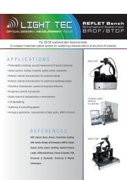
Instruments available for <strong>Scattering</strong> measurement<br />
.<br />
BRDF= Bidirectional Reflected Distributed Function , BTDF= Bidirectional Transmission Distributed Function<br />
REFLET High Specular MINI-DIFF<br />
Type BRDF/BTDF BRDF BRDF/BTDF<br />
Dynamic Range 10 e 9 10 e 13 10 e 4<br />
Wavelength range 400 1700 nm 400 1700 nm 380-800nm<br />
Incident Angles<br />
Tunable<br />
+90° to -90°<br />
Tunable<br />
+90° to 0°<br />
Angular Accuracy
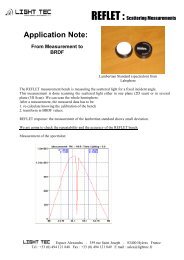
Instruments available for TIS <strong>measurements</strong><br />
TIS = Total Integrated Scattered <strong>Light</strong><br />
• We do have 2 integrating<br />
spheres at <strong>Light</strong><strong>Tec</strong><br />
– One is 10 inches diameter. It is<br />
used for TIS <strong>measurements</strong><br />
– One is 40 inches . It is used for<br />
large samples.
<strong>Scattering</strong> <strong>measurements</strong>:<br />
definition of the scanning planes<br />
• When we use our goniophotometer REFLET, we<br />
are scanning the light distribution in one plane (<br />
one slice) .<br />
• This plane can be the incident plane or any other<br />
plane rotated around the normal to the sample.<br />
• For a 3D BSDF measurement , we do recommend<br />
10 different scanning planes ( 0° , 10°, 20° 30° 40°<br />
50° 60° 70° 80° 90 °)<br />
Scanning in the one plane: 2D BRDF<br />
This image is<br />
animated if you<br />
use the diaporama<br />
model<br />
Scanning in the several planes: 3D BRDF<br />
Step 10 °<br />
6
Case of reflectors<br />
• If the material is a « reflector » then the light is<br />
diffused in a small angle.<br />
• If the divergence of the diffused beam is < 20 ° and ><br />
5 ° , then we increase the accuracy of the<br />
measurement doing 2 bundle of <strong>measurements</strong> :<br />
• The one describer on the previous slide with a step<br />
of 10 ° between the slices<br />
AND<br />
• A second measurement that we call “Near Specular “<br />
where we actually add more scan around the<br />
specular beam with a step of 1 ° between slices.<br />
Step 1 °<br />
• If the divergence of the diffused beam ( < 5 degree)<br />
, please go the slide presenting the measurement of<br />
« High Specular Measurement ”<br />
7
Miscellaneous<br />
• Flatness of the sample<br />
The sample has to be flat , if not the divergent<br />
beam is generated at the same time by the<br />
scattering and the curvature and so it is not<br />
possible to separate both effects<br />
• Anisotropy<br />
In case the surfaces have anisotropic structure ,<br />
we can rotate the incident plan by 90°<br />
<strong>Scattering</strong> only<br />
Curved,<br />
reflecting and<br />
scattering<br />
Curved and<br />
reflecting only<br />
Two 3 D BRDF <strong>measurements</strong> are normally<br />
enough:<br />
-one 3 D BRDF for an incident plane parallel<br />
to the microlines,<br />
- and one 3 D BRDF for an incident plane<br />
perpendicular to the microlines,<br />
X<br />
Y<br />
Z<br />
X<br />
Y<br />
Z<br />
8
Miscellaneous<br />
• Size of the beam<br />
The beam diameter ( spot size on the sample ) can be<br />
tuned from 0.5 mm to 12 mm .<br />
So in case we wan to measured an “hammer” surface ,<br />
it is possible if the perid of the “hemmer “ structure is in<br />
the range of 3 mm max , like this it is average in the<br />
case we do use the lagre beam<br />
• Minimum Incident angles<br />
For BRDF ( reflection ) , when the goniometer is<br />
rotating , the detector is obsturating the incident<br />
lighting beam . We do have a dead zone of 4 ° .<br />
Because of this , we normally do not measure for 0°<br />
incident angle , because then we have no light coming<br />
back on the normal to the surface.<br />
We do recommend a minimum incident angle of 10 ° ,<br />
like this we do have a nice distributed light toward the<br />
normal to the surface<br />
Obstruction 4 °<br />
• Maximum Incident angles<br />
Because of “cosine” consideration , if we use a beam<br />
of 3 mm at the level of the sample , it becomes an<br />
ellipse at the level of the surface. The beam collected<br />
by the receiver as to be smaller than 12 mm at the<br />
level of the sample. For this reason we limit the max<br />
incident angle to 85 ° .<br />
Max incident<br />
angle 85 °<br />
9
Recommended incident angles<br />
As far as these <strong>measurements</strong> are done to<br />
be injected in simulation software, we do the<br />
BSDF characterization for incident angles<br />
close to the real case .<br />
0 ° to 60 °<br />
Example 1 :<br />
For a louver , most of the rays have incident<br />
angles on the reflector of 0° to 60 °<br />
Example 2<br />
For the automotive pointer , most to the TIR<br />
incident angle are between 30° and 90 °<br />
30 ° to 90 °<br />
By default we do recommend to measure<br />
BSDF for 10° 30° 50° 70°<br />
10
Case of transmissive diffusers<br />
Several cases<br />
Measurements to be done<br />
• Transmissive Diffusers used in<br />
transmission only<br />
BTDF<br />
• Transmissive Diffusers used in<br />
transmission and reflection<br />
from one side<br />
FRONT BRDF and BTDF<br />
OR<br />
FRONT BRDF and BTDF<br />
• Transmissive Diffusers used in<br />
transmission and reflection<br />
used from both sides<br />
• Guided diffuser ( TIR)<br />
• Volume diffusers<br />
FRONT BRDF and BTDF<br />
AND<br />
FRONT BRDF and BTDF<br />
TIR BRDF<br />
optional<br />
TIR BTDF<br />
Volume scattering<br />
MIE characterization<br />
11
BTDF <strong>measurements</strong><br />
• When we use our goniophotometer REFLET 180 ,<br />
we are scanning the light distribution in one plane (<br />
one slice) .<br />
• This plane can be the incident plane or any other<br />
plane rotated around the normal to the sample.<br />
• For a 3D BSDF measurement , we do recommend<br />
10 different scanning planes ( 0° , 10°, 20° 30° 40°<br />
50° 60° 70° 80° 90 °)<br />
Scanning in the one plane: 2D BTDF<br />
Scanning in the several planes: 3D BTDF<br />
Step 10 °<br />
12
Back Front BRDF BTDF<br />
In case the interest is for BRDF and BTDF , and if the<br />
diffuser is on one side only , ( the other side is polished) ,<br />
then there are 2 cases :<br />
The light hits first the polished surface = FRONT<br />
The light hits first the diffused surface = BACK<br />
When the measurement is done and has to be set up in<br />
the simulation software , the surface property has to be<br />
applied on the surface ( left or right one) ,<br />
BUT<br />
The diffuser HAS to be set up with a refractive index of 1<br />
as the ambient air.<br />
If the refractive index is not set up as 1 ( 1.5 as the<br />
refractive index of the plastic for example) , then the<br />
software will propagate the light in the diffuser and will<br />
apply Fresnel reflection on the diffused light , and will add<br />
extra scattering not existing.<br />
FRONT<br />
BACK<br />
n WRONG<br />
n CORRECT<br />
13
TIR <strong>measurements</strong><br />
• In case the interest is for the light diffused “ inside” the light<br />
pipe, we need to do a special measurement where the top<br />
surface ( Fresnel losses) has no influence.<br />
• The way to do this is to get the light injected with and<br />
hemispherical lens (24 mm diameter ) towards the surface<br />
diffusing back the light.<br />
• The light is then measured as a normal BRDF or BTDF<br />
• The best sample to measure is a sample where the hemisphere<br />
has exactly the same index as the sample . So ideally we want<br />
to get an hemisphere with the diffuser on the plane surface.<br />
• If this special hemisphere cannot be supplied , we use one of<br />
our hemisphere ( PC) with an “index matching liquid” between<br />
the hemisphere and the sample the be measured.<br />
• It is not perfect , but better than normal BACK BRDF<br />
measurement.<br />
14
TIS <strong>measurements</strong><br />
TIS = Total Integrated Scattered <strong>Light</strong><br />
• It is not possible to get the TIS from a BSDF measurement<br />
• 1 st : a goniophotometer is scanning in a limited number of<br />
planes , so it is not collecting all the scatter light .<br />
• 2 nd : in case of a scatter distribution having a pic around the<br />
specular, the sensor may have not the right dynamic to<br />
measure the exact pic value<br />
• From a BSDF measurement ( BRDF or BTDF ) , we can<br />
calculate the TIS with an accuracy :<br />
– around few % for one diffused sample<br />
– Around 5 % to ….100 % for one specular sample<br />
• Because of these big potential errors , we do recommend that<br />
we also measure the TIS , using an integrating sphere .<br />
15
Wavelength Issues<br />
• What is described in the previous slides is measured with sensors which can work in to wavelength<br />
range :<br />
400 -900 nm and 900- 1700 nm<br />
• The BRDF values delivered are the “TOTAL BRDF integrated” over one wavelength range.<br />
• Filter use : We can use different filters<br />
– Photopic Filter<br />
– Red Filter<br />
– Green Filter<br />
– Blue Filter<br />
– Infrared Filter ( 800 nm )<br />
– Other filters on demands<br />
• Using these filters we do provide a filtered BSDF.<br />
• Spectral BSDF: We can also measure the BSDF values of wavelength from 380 nm to 760 nm .<br />
Please find more info in next slide.<br />
16
Spectral BSDF<br />
The scattering distribution can change versus the color<br />
(wavelength).<br />
In that case we can use an other detector : a<br />
spectroradiometer.<br />
It can measure BRDF or BTDF from 380 to 760 nm.<br />
The result is one BSDF distribution each 4 nm on that<br />
range.<br />
This is a lot of data to handle in one simulation<br />
software.<br />
But we can measure it .<br />
We can do 2D or 3D spectral BSDF.<br />
We recommend 2D , which is already quite complex.
BSDF delivery<br />
• 2D BRDF : In the incident plane, BRDF value each 0.1 °, for each incident angle<br />
• 2D BTDF : In the incident plane, BTDF value each 0.1 °, for each incident angle<br />
• 3D BRDF : 10 different planes ( 0° , 10°, 20° 30° 40° 50° 60° 70° 80° 90 °) , BTDF value each 0.1 °, for each<br />
incident angle :<br />
• 3D BTDF : 10 different planes ( 0° , 10°, 20° 30° 40° 50° 60° 70° 80° 90 °) , BTDF value each 0.1 °, for each<br />
incident angle<br />
• Files delivered<br />
Standard :<br />
text file ( not scripted)<br />
On Demand :<br />
<strong>Light</strong>Tools format , ASTM format ,<br />
Support to generate other format Abg , Gaussian/Lambertian<br />
Support to import in other software ( ASAP, FRED, TRACEPRO, SPEOS, ZEMAX )<br />
18
Volume <strong>Scattering</strong> measurement<br />
• For this case , we are first measuring the 2 D BTDF of the<br />
same sample delivered in 4 different thicknesses.<br />
• Using these 4 BTDF <strong>measurements</strong>, we have developed a<br />
special routine allowing to find the parameter needed to<br />
simulate this material with a Mie <strong>Scattering</strong> model.<br />
• We are delivering 3 parameters<br />
o Radius of the particles<br />
o Density of particles<br />
o Refractive index of particles<br />
• These values are then directly enter in the Mie <strong>Scattering</strong> data<br />
defined in the simulation software.<br />
• On demand we can also deliver Henyey Greenstein model for<br />
diffused material only ( not for specular ones ).<br />
19
High Resolution BDRF<br />
• For some space programs for example , it is important<br />
to measure the <strong>Scattering</strong> data of material with a very<br />
narrow diffusion ( mirrors for example) .<br />
• We can measure as close as 0.02° from the specular.<br />
• 1 D BRDF, very high dynamic 10e 13<br />
• Sources : Laser 532 nm, 633 nm , 808 nm<br />
• Application : High polished mirror, quasi specular<br />
Bench set up :<br />
2 meters long<br />
Detectors:<br />
the REFLET one<br />
+ a set of PMTs+ ADS<br />
Sample + Source holder<br />
set on double goniometer<br />
20
And please , come to visit us !<br />
Our office and<br />
laboratory<br />
location<br />
21