Leica Cyclone – Creating a Mesh and Modeling Surface Topography
Leica Cyclone – Creating a Mesh and Modeling Surface Topography
Leica Cyclone – Creating a Mesh and Modeling Surface Topography

You also want an ePaper? Increase the reach of your titles
YUMPU automatically turns print PDFs into web optimized ePapers that Google loves.
Find GMV content using tags!<br />
Geospatial <strong>Modeling</strong> & Visualization<br />
A Method Store for Advanced Survey<br />
<strong>and</strong> <strong>Modeling</strong> Technologies<br />
GMV Geophysics GPS <strong>Modeling</strong> Digital Photogrammetry 3D Scanning Equipment Data <strong>and</strong> Projects by Region<br />
<strong>Leica</strong> <strong>Cyclone</strong> <strong>–</strong> <strong>Creating</strong> a <strong>Mesh</strong> <strong>and</strong> <strong>Modeling</strong> <strong>Surface</strong> <strong>Topography</strong>: Setting Up<br />
the Model Space <strong>and</strong> Break Lines<br />
This series will show you how create a mesh <strong>and</strong> model surface topography in <strong>Leica</strong>’s <strong>Cyclone</strong><br />
Hint: You can click on any image to see a larger version.<br />
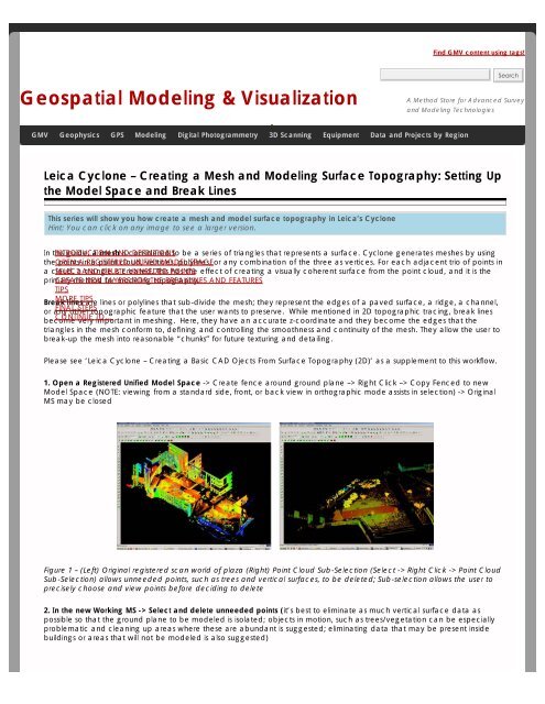
In this INTRODUCTION guide, a mesh AND is considered DEFINITIONSto be a series of triangles that represents a surface. <strong>Cyclone</strong> generates meshes by using<br />
the OPEN points A in REGISTERED a point cloud, UNIFIED vertices, MODEL polylines, SPACEor any combination of the three as vertices. For each adjacent trio of points in<br />
a cloud, SELECT a AND triangle DELETE is created. UNNEEDED This POINTS has the effect of creating a visually coherent surface from the point cloud, <strong>and</strong> it is the<br />
primary CREATE method NEW LAYERS for modeling FOR THE topography. BREAKLINES AND FEATURES<br />
TIPS<br />
Break<br />
MORE<br />
lines<br />
TIPS<br />
are lines or polylines that sub-divide the mesh; they represent the edges of a paved surface, a ridge, a channel,<br />
or any<br />
FINAL<br />
other<br />
STEPS<br />
topographic feature that the user wants to preserve. While mentioned in 2D topographic tracing, break lines<br />
become<br />
CONTINUE<br />
very<br />
TO…<br />
important in meshing. Here, they have an accurate z-coordinate <strong>and</strong> they become the edges that the<br />
triangles in the mesh conform to, defining <strong>and</strong> controlling the smoothness <strong>and</strong> continuity of the mesh. They allow the user to<br />
break-up the mesh into reasonable “chunks” for future texturing <strong>and</strong> detailing.<br />
Please see ‘<strong>Leica</strong> <strong>Cyclone</strong> <strong>–</strong> <strong>Creating</strong> a Basic CAD Ojects From <strong>Surface</strong> <strong>Topography</strong> (2D)’ as a supplement to this workflow.<br />
1. Open a Registered Unified Model Space -> Create fence around ground plane <strong>–</strong>> Right Click <strong>–</strong>> Copy Fenced to new<br />
Model Space (NOTE: viewing from a st<strong>and</strong>ard side, front, or back view in orthographic mode assists in selection) -> Original<br />
MS may be closed<br />
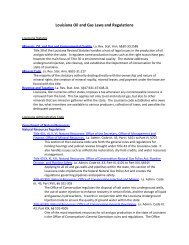
Figure 1 <strong>–</strong> (Left) Original registered scan world of plaza (Right) Point Cloud Sub-Selection (Select -> Right Click -> Point Cloud<br />
Sub-Selection) allows unneeded points, such as trees <strong>and</strong> vertical surfaces, to be deleted; Sub-selection allows the user to<br />
precisely choose <strong>and</strong> view points before deciding to delete<br />
2. In the new Working MS -> Select <strong>and</strong> delete unneeded points (it’s best to eliminate as much vertical surface data as<br />
possible so that the ground plane to be modeled is isolated; objects in motion, such as trees/vegetation can be especially<br />
problematic <strong>and</strong> cleaning up areas where these are abundant is suggested; eliminating data that may be present inside<br />
buildings or areas that will not be modeled is also suggested)
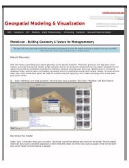
Figure 2 <strong>–</strong> The same plaza as Figure 1 now copied to a working MS <strong>and</strong> “cleaned” of unneeded vertical surfaces <strong>and</strong><br />
vegetation leaving only the ground plane to be modeled.<br />
3. Create new layers for the breaklines <strong>and</strong> features (Shift + L) -> Review the area to be modeled identifying where the<br />
surface changes <strong>and</strong>/or where the user wants a clean break or difference between adjacent surfaces.Create layers for<br />
primary <strong>and</strong> secondary features as needed.<br />
4. Create lines to represent the topography <strong>and</strong> features, assigning an accurate x, y, <strong>and</strong> z coordinate -> There are several<br />
ways to make lines including (1) using 2D drawing methods (covered in ‘<strong>Topography</strong> <strong>and</strong> Site Elements <strong>–</strong> 2D’ above) (2) with<br />
pick points, (3) by extending an existing line (4) by snapping two existing lines together (5) by creating a polyline with Fit<br />
Edge comm<strong>and</strong>, <strong>and</strong> (6) by merging polylines together.<br />
See Help -> Contents -> Search -> ‘Make Lines, Polylines, <strong>and</strong> Breaklines’ for steps for each of these methods.There are<br />
additional variations of each.BEWARE: Lines created by pick points cannot be used for break lines in meshing; if picking<br />
points, be sure to create a polyline rather than a line segment.<br />
5. Tips<br />
A. If drawn in 2D, use Edit Object -> Move/Rotate to move the object to the correct z-coordinate; there are<br />
multiple options moving objects including by a st<strong>and</strong>ard axis <strong>and</strong> pick points.<br />
B. Create additional break lines following the feature or edge of the break lines; place these to break up the mesh<br />
<strong>and</strong> around the boundaries, segmenting out areas where a topographic ground plane is not needed (ie: inside<br />
buildings)
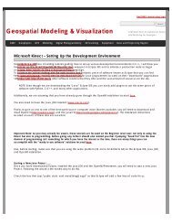
Figure 3 <strong>–</strong> Top view of plaza; Polylines have been created to outline where the sidewalk <strong>and</strong> grass meet; orange h<strong>and</strong>les help highlight the<br />
polylines<br />
More Tips:<br />
C. Use multiple views to confirm line is properly located at all angles <strong>and</strong> h<strong>and</strong>le constraints (Edit Object -> H<strong>and</strong>les<br />
constrain to -> Various options <strong>–</strong> NOTE: once placed in top view, constraining h<strong>and</strong>les to z-direction helps placement<br />
in 3D)<br />
D. Try different methods to see what works for you.With all, use multiple views to confirm the line is properly located<br />
at all angles<br />
Figure 4 <strong>–</strong> (Left) Although from Top View, the breakline looks correct, inspection from a different angle reveals that it is not correct (Right) H<strong>and</strong>les<br />
<strong>and</strong> constraints (Edit Object -> H<strong>and</strong>les -> Constrain Motion) are used to pull the polyline into the correct position <strong>–</strong> every section of every breakline<br />
should be inspected from multiple views<br />
6. Create h<strong>and</strong>les at places where polylines intersect (Select line -> ALT + Select point on line for new h<strong>and</strong>le to help snap<br />
lines together).<br />
7. Delete all points beyond boundary of mesh -> Select polyline representing boudary of mesh -> Right click -> Fence -> From<br />
Selection -> Fence -> Delete outside<br />
8. Delete points within other breaklines to remove any remaining points that should not be considered in the creation of the<br />
mesh -> Copy final breaklines to original or temporary working space in case altered/needed in future<br />
8. Unify points reducing spacing to 1 foot to start <strong>and</strong> adjust settings for desired results.
Continue to <strong>Creating</strong> the Topographic <strong>Mesh</strong><br />
You are reading the series: <strong>Leica</strong> <strong>Cyclone</strong> - <strong>Creating</strong> a <strong>Mesh</strong> <strong>and</strong> <strong>Modeling</strong> <strong>Surface</strong> <strong>Topography</strong> (2.5D)<br />
<strong>Leica</strong> <strong>Cyclone</strong> <strong>–</strong> <strong>Creating</strong> a <strong>Mesh</strong> <strong>and</strong> <strong>Modeling</strong> <strong>Surface</strong> <strong>Topography</strong>: Setting Up the Model Space <strong>and</strong> Break Lines<br />
<strong>Leica</strong> <strong>Cyclone</strong> <strong>–</strong> <strong>Creating</strong> a <strong>Mesh</strong> <strong>and</strong> <strong>Modeling</strong> <strong>Surface</strong> <strong>Topography</strong>: <strong>Creating</strong> the Topographic <strong>Mesh</strong><br />
Please cite this document as: Payne, Angie. 2012. <strong>Leica</strong> <strong>Cyclone</strong> <strong>–</strong> <strong>Creating</strong> a <strong>Mesh</strong> <strong>and</strong> <strong>Modeling</strong> <strong>Surface</strong> <strong>Topography</strong>:<br />
Setting Up the Model Space <strong>and</strong> Break Lines.CAST Technical Publications Series. Number 7408.<br />
http://gmv.cast.uark.edu/scanning/software/leica-software/leica-cyclone/cyclone-workflows/leica-cyclone-creating-amesh-<strong>and</strong>-modeling-surfacetopography-3/.<br />
[Date accessed: 27 April 2013]. [Last Updated: 9 May 2012]. Disclaimer: All<br />
logos <strong>and</strong> trademarks remain the property of their respective owners.<br />
Login<br />
Log in<br />
© 2013 - Geospatial <strong>Modeling</strong> & Visualization