Leica Cyclone – Creating a Mesh and Modeling Surface Topography
Leica Cyclone – Creating a Mesh and Modeling Surface Topography
Leica Cyclone – Creating a Mesh and Modeling Surface Topography

You also want an ePaper? Increase the reach of your titles
YUMPU automatically turns print PDFs into web optimized ePapers that Google loves.
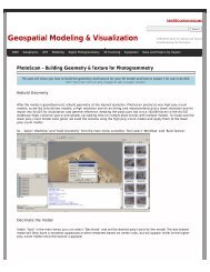
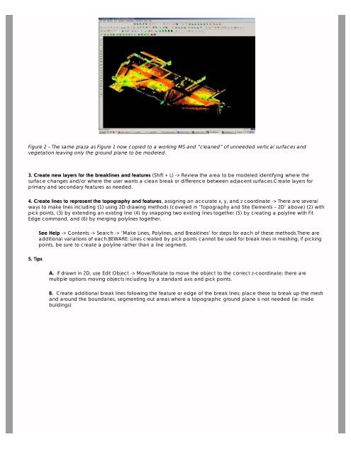
Figure 2 <strong>–</strong> The same plaza as Figure 1 now copied to a working MS <strong>and</strong> “cleaned” of unneeded vertical surfaces <strong>and</strong><br />
vegetation leaving only the ground plane to be modeled.<br />
3. Create new layers for the breaklines <strong>and</strong> features (Shift + L) -> Review the area to be modeled identifying where the<br />
surface changes <strong>and</strong>/or where the user wants a clean break or difference between adjacent surfaces.Create layers for<br />
primary <strong>and</strong> secondary features as needed.<br />
4. Create lines to represent the topography <strong>and</strong> features, assigning an accurate x, y, <strong>and</strong> z coordinate -> There are several<br />
ways to make lines including (1) using 2D drawing methods (covered in ‘<strong>Topography</strong> <strong>and</strong> Site Elements <strong>–</strong> 2D’ above) (2) with<br />
pick points, (3) by extending an existing line (4) by snapping two existing lines together (5) by creating a polyline with Fit<br />
Edge comm<strong>and</strong>, <strong>and</strong> (6) by merging polylines together.<br />
See Help -> Contents -> Search -> ‘Make Lines, Polylines, <strong>and</strong> Breaklines’ for steps for each of these methods.There are<br />
additional variations of each.BEWARE: Lines created by pick points cannot be used for break lines in meshing; if picking<br />
points, be sure to create a polyline rather than a line segment.<br />
5. Tips<br />
A. If drawn in 2D, use Edit Object -> Move/Rotate to move the object to the correct z-coordinate; there are<br />
multiple options moving objects including by a st<strong>and</strong>ard axis <strong>and</strong> pick points.<br />
B. Create additional break lines following the feature or edge of the break lines; place these to break up the mesh<br />
<strong>and</strong> around the boundaries, segmenting out areas where a topographic ground plane is not needed (ie: inside<br />
buildings)